project manual proposed equivalent product procedures.docx 08/10 section 002600 ... atterberg limit...
TRANSCRIPT

PROJECT MANUAL
A/E Project No. 16-4020 OTTUMWA COMMUNITY SCHOOL DISTRICT OTTUMWA SCHAFER STADIUM CONCOURSE UPGRADES 1401 E. 4TH STREET OTTUMWA, IOWA for: OTTUMWA COMMUNITY SCHOOL DISTRICT 1112 N. VAN BUREN OTTUMWA, IOWA 52501 by:
Engineer: KLINGNER & ASSOCIATES, P.C. 604 Liberty Street, Suite 125 Pella, Iowa 50219 (515) 612-7402 March 2018

Ottumwa Community School District Project No. 16-4020 Ottumwa Schafer Stadium Concourse Upgrades March 2018 Ottumwa, IA
000103 - 1 000103-000 Project Directory.doc September 2006
SECTION 000103 PROJECT DIRECTORY
OWNER: Ottumwa Community School District 1112 N. Van Buren Ottumwa, IA 52501 (641) 684-6597 Chuck Bray, Director of Buildings and Grounds Email: [email protected]
ENGINEER: Klingner & Associates, P.C. 604 Liberty Street, Suite 125 Pella, IA 50219 (515) 612-7402 Alan D. Lukens, P.E., S.E.
CIVIL: Klingner & Associates, P.C. 616 N. 24th St. Quincy, IL 62301 (217) 223-3670 Curt S. Wavering, P.E.
END OF SECTION 000103

This Page Left Blank Intentionally

SEALS/CERTIFICATIONS
November 2016 000107 16-4020
KLA KLINGNER & ASSOCIATES, P.C. 604 Liberty St., Suite 125 Pella, Iowa 50219 I HERE BY CERTIFY THAT THIS ENGINEERING DOCUMENT WAS PREPARED BY ME OR UNDER MY DIRECT PERSONAL SUPERVISION AND THAT I AM A DULY LICENSED PROFESSIONAL ENGINEER UNDER THE LAWS OF THE STATE OF IOWA.
Alan D. Lukens __________ _______________ MY LICENSE RENEWAL DATE IS: December 31, 2018 IOWA REGISTRATION NUMBER: 13201 PAGES OR SHEETS COVERED BY THIS SEAL: PROJECT MANUAL DIVISIONS: 02 thru 32 DATE OF ISSUANCE: 03/27/2018
KLA KLINGNER & ASSOCIATES, P.C. 616 North 24th St. Quincy, IL 62301 I HERE BY CERTIFY THAT THIS ENGINEERING DOCUMENT WAS PREPARED BY ME OR UNDER MY DIRECT PERSONAL SUPERVISION AND THAT I AM A DULY LICENSED PROFESSIONAL ENGINEER UNDER THE LAWS OF THE STATE OF IOWA.
Curt Stephen Wavering ___________________________
MY LICENSE RENEWAL DATE IS: December 31, 2018 IOWA REGISTRATION NUMBER: 20408 PAGES OR SHEETS COVERED BY THIS SEAL: PROJECT MANUAL DIVISIONS: Division 02 thru 33 DATE OF ISSUANCE: 03/27/2018

This Page Left Blank Intentionally

Ottumwa Community School District Project No. 16-4020 Ottumwa Schafer Stadium Concourse Upgrades March 2018 Ottumwa, IA
000110 - 1 000110-000 Table of Contents.doc
SECTION 000110 TABLE OF CONTENTS
DIVISION 00 – PROCUREMENT AND CONTRACTING REQUIREMENTS
000101 Project Title Page 000103 Project Directory 000107 Seals Page 000110 Table of Contents 001010 Notice of Bid Letting 001116 Advertisement for Bid 002113 Instructions to Bidders – AIA Document A701 002113 Owner’s Instructions to Bidders/Contractors 002215 Supplementary Instructions to Bidders 002600 Proposed Equivalent Product Procedures 003132 Geotechnical Data
Geotechnical Investigation: Schafer Stadium Bleachers-Ottumwa, IA 004200 Bid Proposal 004313 Bid Security Form 004325 Proposed Equivalent Product Request Form 004336.10 Proposed Subcontractors Form 005100 Notice of Award 005200 Standard Form of Agreement – AIA Document A101 005500 Notice to Proceed 006113 Performance and Payment Bond Form 007200 General Conditions 007210 Standard General Conditions – AIA Document A201 007300 Supplementary Conditions 008600 Schedule of Drawings
DIVISION 01 – GENERAL REQUIREMENTS
011000 Summary of Work 011419 Use of Site 013100 Project Management and Coordination 013216 Construction Progress Schedule 013300 Submittal Procedures 014500 Quality Control 014529 Testing Laboratory Services 015000 Temporary Facilities and Controls 016600 Product Storage and Handling Requirements 017400 Cleaning and Waste Management 017700 Closeout Procedures 017839 Project Record Documents
DIVISION 02 – EXISTING CONDITIONS
024100 Demolition 024120 Subsurface Conditions
DIVISION 03 – CONCRETE
030131 Rehabilitation of Cast In Place Concrete 031000 Concrete Forms and Accessories 032000 Concrete Reinforcing

Ottumwa Community School District Project No. 16-4020 Ottumwa Schafer Stadium Concourse Upgrades March 2018 Ottumwa, IA
000110 - 2 000110-000 Table of Contents.doc
033000 Cast-In-Place Concrete DIVISION 05 – METALS 051200 Structural Steel Framing DIVISION 09 – FINISHES 099113 Exterior Painting DIVISION 26 – ELECTRICAL 260500 Common Work Results for Electrical 260519 Low Voltage Electric Power Conductors and Cables 260526 Grounding and Bonding for Electrical Systems 265600 Exterior Lighting DIVISION 31 – EARTHWORK 310515 Soils for Earthwork 310516 Aggregates for Earthwork 311600 Site Preparation 312213 Rough Grading 312220 Landscape Grading 312316 Excavation 312324 Backfill DIVISION 32 – EXTERIOR IMPROVEMENTS 321123 Aggregated Base Courses 321313 Concrete Paving 323113 Chain Link Fences and Gates 323224 Modular Black Retaining Walls 329219 Seeding END OF SECTION 000110

Ottumwa Community School District Project No. 16-4020 Ottumwa Schafer Stadium Concourse Upgrades March 2018 Ottumwa, IA
001010 - 1 001010 Notice of Bid Letting.doc
SECTION 001010 NOTICE OF BID LETTING
CONTRACTORS: NOTICE OF PUBLIC BID LETTING FOR THE OTTUMWA COMMUNITY SCHOOL DISTRICT OTTUMWA SCHAFER STADIUM CONCOURSE UPGRADES, OTTUMWA, IOWA AND THE TAKING OF BIDS THEREFORE. NOTICE IS HEREBY GIVEN that sealed proposals will be received by the Ottumwa Community School District for the Ottumwa Schafer Stadium Concourse Upgrades until 2:00 p.m. on April 17, 2018. Sealed proposals shall be submitted to the Board Secretary, Ottumwa Community School District, 1112 N. Van Buren, Ottumwa, IA 52501. Proposals will be publicly opened and read immediately thereafter in the superintendant’s conference room at the same address for the flowing public improvements: Ottumwa Schafer Stadium Concourse Upgrades Bids will be received for one single prime contract. Any proposals received after that time and place will be returned to the bidder unopened. Each bid shall be made on a form furnished by the Architect and shall be sealed in an envelope separate from the envelope containing the certified check or bid bond and shall be clearly marked as such. A certified check or bid bond in the amount of 5% of the base bid on a solvent bank, made payable to the Ottumwa Community School District shall be filed in a separate envelope with each bid. This check or bid bond may be cashed and the proceeds retained by the District as liquidated damages if the bidder fails to execute a contract and file and approved bond equal to 100% of the contract price by a responsible surety for the faithful performance of the contract. Drawings, Project Manual, Addenda, List of Plan Holders of Record, and ultimately Bid Tabulations are available thru Rapids Reproductions Inc., 6015 Huntington Ct. NE., Cedar Rapids, IA 52402 (319-364-2473) at no cost for each set of documents. Rapids Reproductions Inc. requests Contractors order copies from their website prior to pickup. The freight cost for documents that are shipped is non-refundable, or a UPS Account number can be used in place of a check. The website is www.rapidsrepro.com. Only one complete set of documents may be obtained per party. It is the desire of the Architect to reduce the number of printed sets to a minimum and the Architect invites Contractors to review the project details to confirm their interest prior to requesting sets. Any questions concerning this document solicitation process shall be directed to Cheryl Dietz at 319-364-2473. Any technical questions regarding interpretations of documents shall be directed to the Architect, Klingner & Associates at 515-612-7402, not Rapids Reproductions Inc. Bidding documents may be examined at the following places: Master Builders of Iowa, 221 Park Street, Box 695, Des Moines, IA 50303 McGraw Hill Construction Dodge, 2507 Ingersoll Avenue, Des Moines, IA 50312 Northern Iowa Builders Exchange, 25 West State Street, Suite B, P.O. Box 1154, Mason City, IA 50401 Sioux City Construction League, 3911 Stadium Dr., Sioux City, IA 51106 F.W. Dodge Corporation, 1910 East Kimberly Road, Davenport, IA 52807 Omaha Builders Exchange, 4255 S. 94th Street, Omaha, NE 68127 Minneapolis Builders Exchange, 1123 Glenwood Avenue, Minneapolis, MN 55405 Associated General Contractors of Quincy, 215 Oak Street, Quincy, IL 62301

Ottumwa Community School District Project No. 16-4020 Ottumwa Schafer Stadium Concourse Upgrades March 2018 Ottumwa, IA
001010 - 2 001010 Notice of Bid Letting.doc
IlIowa Builders Exchange, Inc., 520 24th Street, P.O. Box 4930, Rock Island, IL 61201 A Non-Mandatory Pre-bid Conference will be held at the project site on April 4, 2018 at 10:00 AM. The award of the contract may be made by the Board of Directors of the Ottumwa Community School District to the lowest responsive responsible bidder in accordance with the provisions of §26.9 of the Iowa code, meeting the specifications. The right is reserved to reject any or all bids, or any part thereof, and to waive informalities and to enter into such contract as shall be deemed in the best interest of the District. By virtue of statutory authority, a preference will be given to products and provisions grown or produced within the State of Iowa and to Iowa domestic labor. No bid may be withdrawn for a period of 30 calendar days after the date of opening. All bids will be goverened by provisions of the Iowa Code and by Board policies. This project is sales tax exempt. The owner will issue an exemption certificate for the purchase or use of building materials, supplies, and equipment that will be used in the performance of the construction contract. Secretary of the Board of Directors Ottumwa Community School District END OF SECTION 001010

Ottumwa Community School District Project No. 16-4020 Ottumwa Schafer Stadium Concourse Upgrades March 2018 Ottumwa, IA
001116 - 1 001116-090 Advertisement For Bids.doc
SECTION 001116 ADVERTISEMENT FOR BIDS 1. Sealed bids will be received by Ottumwa Community School District for construction of the
following:
Ottumwa Schafer Stadium Concourse Upgrades
Bids will be received at the place, time, and date hereinafter stated:
BIDS RECEIVED AT: OTTUMWA COMMUNITY SCHOOL DISTRICT OFFICE
1112 N. VAN BUREN OTTUMWA, IOWA 52501
TIME: 2:00 P.M.
DATE: April 17, 2018 Any proposals received after that time and place will be returned to
the bidder unopened. Each bid shall be made on a form furnished by the architect and shall be sealed in an envelope separate from the envelope containing the certified check or bid bond and shall be clearly marked. 2. Drawings and specifications will be made available on March 28, 2018 and ultimately a bid
tabulation will be available thru Rapids Reproductions Inc., 6015 Huntington Ct. NE., Cedar Rapids, IA 52402 (319-364-2473) at no cost for each set of documents. Rapids Reproductions Inc. requests Contractors order copies from their website prior to pick up. The freight cost for documents that are shipped are non-refundable, or a UPS Account number can be used in place of a check. The website is www.rapidsrepro.com. Only one complete set of documents may be obtained per party. It is the desire of the Architect to reduce the number of printed sets to a minimum and the Architect invites Contractors to review the project details to confirm their interest prior to requesting sets. Any questions concerning this document solicitation process shall be directed to Cheryl Dietz, Rapids Reproductions Inc. at 319-364-2473. Any technical questions regarding interpretations of documents shall be directed to the Architect, Klingner & Associates at 515-612-7402, not Rapids Reproductions Inc.
3. Drawings and specifications can be reviewed and received by bidder at the following locations:
Klingner & Associates, P.C., Inc. 604 Liberty Street, Suite 125 Pella, IA 50219
4. For the purpose of providing additional information for bidders, a Non-Mandatory Pre-bid Conference will be held on April 4, 2018 at 10:00 AM at the Ottumwa Schafer Stadium site.
4. A certified check or bid bond in the amount of 5% of the base bid on a solvent bank, made payable to the Ottumwa Community School District shall be filed in a separate envelope with each bid. This check or bid bond may be cashed and the proceeds retained by the District as liquidated damages if the bidder fails to execute a contract and file an approved bond equal to 100 % of the contract price by a responsible surety for the faithful performance of the contract.

Ottumwa Community School District Project No. 16-4020 Ottumwa Schafer Stadium Concourse Upgrades March 2018 Ottumwa, IA
001116 - 2 001116-090 Advertisement For Bids.doc
5. Owner reserves the right to reject any and all bids, to accept other than the lowest bid, and to waive any irregularities or informalities in bids received.
6. The project includes paving demolition and the paving of a new concourse including ramp repair,
retaining wall improvements, fencing, and walkway lighting for the Ottumwa Schafer Stadium. The award of the contract may be made by the Board of Education of the Ottumwa Community School District to the lowest responsive responsible bidder in accordance with the provisions of §26.9 of the Iowa code, meeting the specification. The right is reserved to reject any or all bids, or any part thereof, and to waive informalities and to enter into such contract as shall be deemed in the best interests of the District. By virtue of statutory authority, a preference will be given to products and provisions grown or produced within the State of Iowa and to Iowa domestic labor. No bid may be withdrawn for a period of 30 calendar days after the date of opening. All bids will be governed by provisions of the Iowa Code and by Board policies. This project is sales tax exempt. The owner will issue an exemption certificate for the purchase or use of building materials, supplies, and equipment that will be used in the performance of the construction contract. Secretary of the Board of Directors Ottumwa Community School District END OF SECTION 001116


Ottumwa Community School District Project No. 16-4020 Ottumwa Schafer Stadium Concourse Upgrades March 2018 Ottumwa, IA
002113 - 1 002113-060 Owners Instructions to Bidders & Contractors.doc
SECTION 002113 OWNER’S INSTRUCTIONS TO BIDDERS/CONTRACTORS 1. Purpose of Instructions: It is the purpose of these instructions to make known to interested
bidders information which may affect their bids or their work on this Project. In addition to these instructions, there will be A.I.A. Instructions to Bidders. Bidders are advised to the extent that the Owner’s instructions conflict or confuse the A.I.A. Instructions to Bidders, the instructions of the Owner control. The successful bidder becomes the contractor.
2. OWNER The "Owner" is: OTTUMWA COMMUNITY SCHOOL DISTRICT 1112 N. VAN BUREN
OTTUMWA, IOWA 52501 3. PROJECT The "Project" is: OTTUMWA COMMUNITY SCHOOL DISTRICT OTTUMWA SCHAFER STADIUM CONCOURSE UPGRADES
1401 E. 4TH STREET
OTTUMWA, IOWA 52501 4. BIDS REQUESTED/SCOPE OF WORK
Bids for construction of the Project will be received in one (1) general bid form which is defined in the Architect/Engineer’s specifications. Bidder will bid on all related work as specified on bidding documents, which include: (1) Owner’s Instructions to Bidder/Contractor; (2) General Conditions of Contract; and (3) construction documents.
This project is generally described as:
Concourse Upgrades to include pavement demolition and the paving of a new concourse including ramp repair, retaining wall improvements, fencing, and walkway lighting for the Ottumwa Schafer Stadium.
5. BIDS
Bids shall be made on the form provided by the Architect/Engineer. Bid Forms shall become a part of the Contract documents.
No Bid submitted will be considered by the Owner unless such Bid is accompanied by a Bid Bond made payable to: Ottumwa Community School District 1112 N. Van Buren Ottumwa, Iowa 52501
in the amount of 5% of the bid. A certified check or bank draft payable to the order of Ottumwa Community School District in such amount is an acceptable Bid Bond.
Said Bid Bond shall be forfeited to the Owner in the event that any bidder to whom a contract is awarded fails to enter into Contract with the Owner for the work proposed in Bid. Bid Bonds will be returned to unsuccessful bidders not later than fourteen (14) days after the formation of the Contract with a successful bidder.

Ottumwa Community School District Project No. 16-4020 Ottumwa Schafer Stadium Concourse Upgrades March 2018 Ottumwa, IA
002113 - 2 002113-060 Owners Instructions to Bidders & Contractors.doc
6. DELIVERY OF PROPOSAL Proposal shall be delivered to the Ottumwa Community School District, 1112 N. Van Buren,
Ottumwa, Iowa 52501 Attn: Ottumwa Schafer Stadium Renovation, in an opaque envelope marked "Sealed Bid" bearing the title of the project, and the name of the bidder.
7. PERFORMANCE AND LABOR/MATERIAL PAYMENT BONDS The successful bidder, to whom a Contract is awarded, shall provide the Owner, within a period of fourteen (14) days following the date of the notice of such award, a Surety Company’s Performance Bond and a Labor/Material Payment Bond, each in an amount equal to one hundred percent (100%) of the Contract Amount. Bonds shall remain in effect until total completion of project. The Surety Company must have a Policy Holder’s rating of A or better and a Financial Rating of Class XII or high in the A.M. Best Company’s "KEY RATING GUIDE," and the form used will be acceptable to the Owner. The cost of the Bonds shall be included in the Contractor’s Proposal. 8. CONTRACT AWARD
The Bid shall be awarded to one single Contractor for the work as identified. The intended schedule is as follows: Board awards Contract April 23, 2018 Notice of Award April 24, 2018 Construction to begin May 10, 2018
Pursuant to Iowa Code, awards will be made to the lowest responsive responsible bidder in accordance with the provisions of §26.9 of the Iowa code, as reasonably determined by the Board of Education considering conformity with specifications, terms of delivery, quality and serviceability. In evaluating these factors, the Board will necessarily consider and compare (relative to the other bidders) the experience of the bidder on this type of project or similar projects, AND the performance history of the bidder regarding conformity with specifications, meeting terms of delivery and quality of work AND the performance history and ability of the bidder to complete the project on time, to service the product (including response time to service calls) and workmanship on the project. THE BOARD OF EDUCATION IS NOT OBLIGATED TO ACCEPT THE LOWEST DOLLAR BID AND RESERVES THE RIGHT TO REJECT ANY AND ALL BIDS OR TO WAIVE ANY INFORMALITIES, IRREGULARITIES, TECHNICALITIES, OR DEFECTS IN ANY BID SHOULD THE BOARD DEEM IT IN THE BEST INTEREST OF THE SHOOL DISTRICT TO DO SO.
9. EXAMINATION OF SITE The Bidder shall carefully examine the site and scope of work. No pleas of ignorance of conditions that exist or conditions or difficulties that may be encountered in the execution of the work as a result of failure to make a proper examination and investigation will be accepted as an excuse for any failure or omission on the part of the Bidder to fulfill in every detail all of the requirements of the Bidding Documents or will be accepted as a basis for any claims whatsoever for extra compensation. 10. FAMILIARIZATION WITH THE WORK Before submitting his bid, the Bidder shall familiarize himself with the work, rules governing acceptance of his work, site where the work is performed, labor conditions, the conditions and

Ottumwa Community School District Project No. 16-4020 Ottumwa Schafer Stadium Concourse Upgrades March 2018 Ottumwa, IA
002113 - 3 002113-060 Owners Instructions to Bidders & Contractors.doc
facilities at the site for delivery and installation, all laws, regulations and other factors affecting performance of the work. The prospective bidder shall carefully correlate his observations with the requirement of the bidding documents and contact drawings, and otherwise satisfy himself of the expense and difficulties attending performance of the work, including delivery of material and equipment. The submission of a bid will constitute an incontrovertible representation by the bidder that he has complied with every requirement of this paragraph. 11. INTERPRETATION OR CORRECTION OF BIDDING DOCUMENTS
The Work includes not only Work specified on or obvious from the Contract Documents, including but not limited to plans, specifications, and drawings, but also such Work as would be reasonably implied or expected in view of the nature, character and purpose of the Project. Before construction begins, the Contractor will review the finalized Contract Documents and confirm in writing such review. Unless the Contractor notifies Owner and Architect in writing to the contrary before construction commences, it shall be presumed that no change in payments due to the Contractor will be required because of any changes, modifications or refinements to or in the Contract Documents from earlier versions. Should any change in payment be expected or sought, the Owner reserves the right to cancel and rescind this contract without further obligation to the Contractor. The Owner and Contractor may, however, agree to change orders.
12. SPECIFIED MATERIALS AND EQUIPMENT a) No alterations or changes in the Plans, Specifications, or other instructions enclosed shall be permitted without express written consent of the Owner and Architect. b) Any prospective bidder who discovers ambiguities or is in doubt as to the true meaning of
any part of the Bidding Documents shall promptly request Architect for an interpretation thereof.
c) Interpretations will be made only by Addenda, duly issued, and copies of each Addendum will be mailed or delivered to each Bidding Document holder of record. d) Unless otherwise specified the Contractor shall provide all materials, tools, automotive
and other construction equipment, which may be necessary for the completion of the work described in the specifications. The Contractor shall keep a competent representative on the job and employ persons skilled in the various phases of the work involved. All work shall be performed in a workmanlike manner.
e) Products and manufacturers not named or specified may be considered upon request in
writing to the Architect. Products and manufacturers not specifically named or specified in the Bidding Documents, or Addenda or approved by the Architect will not be considered for use on this Project.
13. FAILURE TO EXECUTE CONTRACT
Failure to comply with any of the requirements of these Instructions to execute the Contract within Fifteen (15) days after notice of award as specified or to furnish specified bonds and certificates of insurance as required shall be just cause for the annulment of the award. In the event of such annulment of the award, the amount of the bid bond shall become the property of the Owner, not as a penalty, but as liquidated damages. Award may then be made to the next lowest responsible bidder as determined in accord with paragraph 8.
14. ACCESS, STORAGE, ETC. ON SITE
The Contractor shall have access 7:00 AM to 7:00 PM during school days and during non-school days to that portion of the site on which construction is involved. On-site storage of materials and equipment shall be subject to the written approval of Owner. The Contractor shall adjust the

Ottumwa Community School District Project No. 16-4020 Ottumwa Schafer Stadium Concourse Upgrades March 2018 Ottumwa, IA
002113 - 4 002113-060 Owners Instructions to Bidders & Contractors.doc
schedule as required for school activities. 15. PROTECTION OF BUILDING, SITE AND ADJOINING PROPERTIES The Contractor shall be required to take the necessary precautionary measures to insure the protection of the building, site and adjoining properties from damage of any kind resulting from work on this Project. All costs of such precautionary measures, as well as the costs incurred in repair or replacement of damage inflicted, will be borne by the Contractor as a part of his work on this Project. 16. TAX EXEMPT All bidders are hereby notified that this Project is exempt from Sales Tax on all materials. No bid shall, therefore, include such tax. 17. SCHEDULING OF WORK – STARTING DATES/ SUBSTANTIAL COMPLETION AND FINAL
COMPLETION OF WORK
It is the intent of these Instructions to require aggressive progress to achieve completion once the project is started. The General Contractor shall satisfy himself that the project can be completed within the construction schedules established herein and shall confirm thus schedules by positively responding to completion dates on the Bid Proposal.
Construction Schedules: The work shall commence following award of contract and as soon as possible upon ‘Notice to Proceed’ (see Article 13 of this section). Final Completion of the work shall be August 9th, 2018. “Substantial Completion” shall defined as a condition when the Owner accepts the certification of the Architect that construction is sufficiently complete in accordance with the contract documents so that the designated portion of the project may be occupied for the use intended.
"Final completion" shall be defined as a condition when the Contractor is 100% complete with any and all work (including punch list items), areas of the building under this contract are ready for occupancy and usage by the District, and all of the Contractor’s equipment, tools, and supplies are removed from the site.
18. PRE-BID MEETING, SITE INSPECTION
Interested bidders shall visit the job site prior to Bid Due Date to familiarize themselves with job conditions and to ascertain the extent of required work necessary to complete installation as specified. A Non-Mandatory Pre-Bid Meeting will be held at the project site at the time and location indicated in Section 001116. To obtain access to the facilities and schedule an additional site visit, Bidder shall call for an appointment.
19. SITE RESTRICTIONS
THE USE OF TOBACCO ON ALL SCHOOL PROPERTY IS PROHIBITED. THIS MEANS THAT INSIDE AND OUTSIDE OF ALL BUILDINGS NO USE OF TOBACCO PRODUCTS WILL BE PERMITTED.
20. DAILY CLEANUP Contractor shall provide daily clean up of material and tools in work areas at the close of each workday unless otherwise approved in writing by the Owner or Architect. 21. WRITTEN SPECIFICATIONS

Ottumwa Community School District Project No. 16-4020 Ottumwa Schafer Stadium Concourse Upgrades March 2018 Ottumwa, IA
002113 - 5 002113-060 Owners Instructions to Bidders & Contractors.doc
NO DEVIATION FROM THE BIDDING DOCUMENTS WILL BE PERMITTED OR ACCEPTED WITHOUT WRITTEN AUTHORIZATION, SIGNED BY BOTH THE ARCHITECT AND THE OWNER.
22. STATUTORY REQUIREMENTS All applicable Federal and State laws, and the rules and regulations of all authorities having jurisdiction over construction of the project, shall apply to the Contract throughout, and they will be deemed to be included in the contract the same as though written therein full. 23. PROTECTIVE PRECAUTIONS The Bidder, upon receiving contract acceptance, shall be able to proceed with work immediately after the published start date, subject to the following conditions. a) Submit, discuss and obtain approval of the proposed schedule of work from the Owner and the Architect. b) Every precaution must be taken to prevent any damage, loss or injury to any person, or to any property of the Owner. c) All utilities on the properties shall be kept in proper operating condition at all times.
Should there be a need to temporarily disconnect any systems, the Contractor shall notify, in writing, the following entities, when the existing system is going to be inoperative, and that the building will be without a particular service for a period not to exceed one (1) day. Give a minimum of two days notice to:
1. Owner. 2. Architect. 3. The Fire Department. 4. Any other entity or department appropriate or responsible for a specific service. d) The same notification shall be provided by the Contractor if any of the other utilities will be temporarily inoperative. e) It is mandatory that the fire lanes be kept free of any obstructions at all times, unless otherwise authorized by the Owner and the Fire Department. f) Parking for construction workers will be in areas as discussed with and designated by Owner, and must be strictly adhered to. g) All fire alarm, security alarm, any other type of protection system and supervisory alarm
MUST BE operable at all times when the property is occupied or could be occupied. If one of the systems is down, the Owner, Architect, fire department, and any other entity or department appropriate or responsible for a specific service must be notified. The Contractor is responsible for monitoring and maintaining these systems to be operable and in safe condition at all times.
24. ASBESTOS/HAZARDOUS MATERIAL No forms or types of asbestos or asbestos-containing products are permitted in this building project. By submitting a proposal of this project, the prime contractors and subcontractors, suppliers, etc. guarantee that no asbestos-containing products are being included. In accordance with 40 CFR Part 763 which pertains to Asbestos Containing Materials and the Hazard Communication Standard (HCS) 29 CFR 1910.1200 notification is hereby given that

Ottumwa Community School District Project No. 16-4020 Ottumwa Schafer Stadium Concourse Upgrades March 2018 Ottumwa, IA
002113 - 6 002113-060 Owners Instructions to Bidders & Contractors.doc
asbestos containing materials and/or chemicals may exist within the School District buildings which you and/or your employees must be made aware. Owner will meet the HCS and requirements for notification of short term workers by posting a notice on entrance doors of its buildings which will advise contractors, repair persons, installers, delivery persons, vendors and visitors to register in the Main Office where both the Asbestos Management Plan and Material Safety Data Sheets (MSDS) for chemicals can be viewed. In the event that previously unknown asbestos containing building materials (ACBM) or other hazardous materials are suspected and/or discovered in the course of work on this project, work shall cease and the Owner and Architect shall be notified immediately. Owner further advises that any hazardous chemicals which you plan to bring into the School District Buildings during the performance of your work must be disclosed to Owner before bringing them upon the premises. This may be accomplished by either calling the information contained on the MSDS for that project to the Board Office or by faxing a copy of the MSDS to the Board Office. Contractor will comply with all OSHA requirements, specifically including but not limited to the Hazard Communication Standard 29 CFR 1910.1200, Control of Hazardous Energy Standard 29 CFR 1910.147, and Combined Space Entry 29 CFR 1910.146. 25. Owner’s designated contact person on this project will be Chuck Bray, Director of Buildings and
Grounds Ottumwa Community School District. 26. Insurance Requirements See Supplementary Conditions 007300 27. SCHOOL BOARD – REQUESTS FOR INFORMATION FROM INDIVIDUAL MEMBERS OF THE BOARD OF EDUCATION The Superintendent and the administrative team will make every effort to keep the Board of Education informed in all matters of business it deals with in the course of carrying out its duties. From time to time the Board as a whole may request more information than was provided to them. Such requests will be acted upon by the entire Board of Education in the form of a directive to the Superintendent. Individual members of the Board of Education who have requests for special reports, extra information or other data, shall present such requests to the Superintendent who shall respond to such requests in consultation with the President of the Board of Education. The decision of the President and Superintendent is subject to review by the Board of Education. Board members as individuals shall not request information from anyone in the employ of the district, a private contractor doing business with the district or any employee of said contractor but shall make their requests through the Superintendent. 28. The contractor shall not send to any school building or school property any employee or agent who is a child sex offender as defined in the Child Sex Offender and Murdered Community Notification Act. It is the responsibility of the contractor to contact on a regular basis the local law enforcement authority where each employee or agent resides to determine if the employee is on the list of registered felons who have committed child sex offenses. The contractor shall also provide the District with the name and address of each employee who will perform work on school property and require that the employee submit to a criminal history background investigation. 29. PHASING OF WORK AND OCCUPANCY DURING CONSTRUCTION
The Contractor shall confine his work to a limited area of the site all as pre-arranged with the Owner. Certain portions of the work shall be phased so as to accommodate the Owner’s business operations. If any work may disrupt the Owner’s operations (such as electric, plumbing

Ottumwa Community School District Project No. 16-4020 Ottumwa Schafer Stadium Concourse Upgrades March 2018 Ottumwa, IA
002113 - 7 002113-060 Owners Instructions to Bidders & Contractors.doc
or mechanical service) the contractor shall notify the Owner’s representative to coordinate and pre-arrange work as soon as possible before the point in time any disruption may occur. Thus disruptions shall be held to a minimum time period. Phasing and coordination issues related to Owner’s operations will be addressed at the Pre-Construction Meeting.
30. LIQUIDATED DAMAGES
All work shall be at final completion on or before 5:00 PM on August 9, 2018. If contractor fails to reach final completion of this contract on or before 5:00 PM on August 9, 2018, then for each day this contract shall remain uncompleted after August 9, 2018, owner may deduct the sum of $250.00 per each day past the Final completion date from the contract price specified in this contract and retain that sum out of the contract price as payment to owner by contractor of liquidated damages sustained by reason of the failure of contractor to complete this contract on or before the date specified. The owner's right to liquidated damages under this section shall in no event disentitle or foreclose owner's right to additional monetary damages, injunctive relief, or any other remedy available to the owner.
If completion of this contract is delayed and contractor timely makes a claim in writing for and extension of time showing good cause for the delay, then the time of completion of this contract may be extended for an additional period of time. Any claim by contractor for an extension of time must be made in writing to the Owner’s Representative not more than 5 days following the development of the cause for delay.
When good cause for a delay in the work is shown by contractor, The Owner shall determine the
seriousness of the delay and then extend the time of completion of the work accordingly. Such good cause may include changes in the work, strikes, lockouts, or other labor disputes; fire, earthquake, or other natural disasters; unavoidable casualty or damage to personnel, materials, or equipment; delay in receiving materials or equipment; acts or neglect of owner, another contractor employed by owner, or any other person not directly responsible to contractor; or any cause beyond the control of contractor. The contract time shall not be extended due to normal inclement weather. The time of performance as stated in the contract documents includes an allowance for calendar days per month which may not be available for construction out-of-doors.
31. SCHEDULE OF VALUES
The contractor awarded this project will be required to submit a Schedule of Values at the time the Contract is awarded. The Schedule of Values shall be allocated to various portions of the project, prepared in such a form and supported by costs data to substantiate its accuracy as the Architect may require. This schedule shall not only be used as the basis for reviewing the Contractor’s Pay Applications, but will also be used to facilitate in the allocation of funds from funding sources.
END OF SECTION 002113

This Page Left Blank Intentionally
Ottumwa Community School District Project No. 16-4020 Ottumwa Schafer Stadium Concourse Upgrades March 2018 Ottumwa, IA
002215 - 1 002215-090 Supp. Instructions to Bidders.doc
SECTION 002215 SUPPLEMENTARY INSTRUCTIONS TO BIDDERS
AIA Document A701-2007 Edition, Instructions to Bidders, comprise the bidding requirements for this contract.
1. PRECEDENCE OF SUPPLEMENTARY INSTRUCTIONS TO BIDDERS These Supplementary Instructions to Bidders take precedence over the INSTRUCTIONS TO
BIDDERS, AIA Document A701, as hereinafter stated.
2. MODIFICATIONS DELETIONS AND ADDITIONS The supplementary instructions herein modify, delete from, and/or add to the Instructions to
Bidders.
A. Articles, or portions thereof, which are not specifically modified, deleted, or superseded hereby, remain in full effect.
3. INTERPRETATION OR CORRECTION OF BIDDING DOCUMENTS
A. Add Paragraph 3.2.4: The Work includes not only Work specified on or obvious from the Contract Documents, including but not limited to plans, specifications and drawings, but also such Work as would be reasonably implied or expected in view of the nature, character and purpose of the Project. Before construction begins, the Contractor will review the finalized Contract Documents and confirm in writing such review. Unless the Contractor notifies Owner and Architect in writing to the contrary before construction commences, it shall be presumed that no change in payments due to the Contractor will be required because of any changes, modifications or refinements to or in the Contract Documents from earlier versions. Should any change in payment be expected or sought, the Owner reserves the right to cancel and rescind this contract without further obligation to Contractor. The Owner and Contractor may, however, agree to change orders.
4. FORM AND STYLE OF BIDS
A. Refer to paragraph 4.1 of the Instructions to Bidders, add:
4.1.8 Bids shall be submitted on additional bid forms provided to bidders with the bidding documents. Only one copy will be required. Bid forms bound in with these specifications shall not be used and shall not be removed from the set of specifications.
5. BID SECURITY
A. Refer to paragraph 4.2 of the Instructions to Bidders, add:
4.2.4 A bank draft, certified check, or Bid Bond with sufficient surety thereon, made payable to the Owner, in the amount of 5% of the bid shall accompany each bid as a guarantee that the Contractor, if awarded the Contract, will furnish satisfactory Performance and Payment Bond and proceed with the work. Upon failure to do so he shall forfeit the deposit as liquidated damages. No Contractor may withdraw his bid for a period of 30 days after the date set for receiving bids. Bid Securities will, with the exception of the three lowest bidders, be returned as soon as possible after the opening of bids, and the remaining

Ottumwa Community School District Project No. 16-4020 Ottumwa Schafer Stadium Concourse Upgrades March 2018 Ottumwa, IA
002215 - 2 002215-090 Supp. Instructions to Bidders.doc
securities will be returned when the Contract is executed. Bid Bonds shall be written on "Bid Bond", Document A310 of The American Institute of Architects.
6. REJECTION OF BIDS
A. Refer to paragraph 5.2.1 of Instructions to Bidders, change to read as follows: "The Owner reserves the right to reject any and all bids, to accept other than the lowest bid, and to waive any irregularities or informalities in bids received."
7. PERFORMANCE AND PAYMENT BOND
A. Refer to paragraph 7.1 of Instructions to Bidders, change to read as follows: "Successful bidder shall furnish Performance and Payment Bonds in a sum equal to one hundred percent (100%) of the total amount payable by the terms of the Contract. Bonds shall be written on "Performance Bond" and "Payment Bond"; Document A312 of The American Institute of Architects. The term "one hundred percent (100%) of the total amount payable by the terms of the Contract" shall mean the total of the original contract amount and any change orders or modifications thereto.
END OF SECTION 002215

Ottumwa Community School District Project No. 16-4020 Ottumwa Schafer Stadium Concourse Upgrades March 2018 Ottumwa, IA
002600 - 1 002600-000 Proposed Equivalent Product Procedures.docx 08/10
SECTION 002600 PROPOSED EQUIVALENT PRODUCT PROCEDURES
PART 1 - GENERAL
1.1 DEFINITIONS
A. Proposed Equivalent Product: Requests for changes in products, materials, equipment, and methods of construction from those indicated in the Procurement and Contracting Documents, submitted prior to receipt of bids.
1.2 QUALITY ASSURANCE
A. Compatibility of Equivalents: Investigate and document compatibility of proposed equivalent products with related products and materials. Engage a qualified testing agency to perform compatibility tests recommended by manufacturers.
1.3 PROPOSED EQUIVALENT PRODUCT
A. Proposed Equivalent Product, General: By submitting a bid, the Bidder represents that its bid is based on materials and equipment described in the Procurement and Contracting Documents, including Addenda. Bidders are encouraged to request approval of qualifying equivalent materials and equipment when the Specifications Sections list materials and equipment by product or manufacturer name.
B. Proposed Equivalent Product will be received and considered by Owner when the following conditions are satisfied, as determined by Architect; otherwise requests will be returned without action:
1. Extensive revisions to the Contract Documents are not required. 2. Proposed changes are in keeping with the general intent of the Contract Documents,
including the level of quality of the Work represented by the requirements therein. 3. The request is made on the Proposed Equivalent Product Request Form included in the
Bidding Document, is fully documented, and properly submitted.
1.4 SUBMITTALS
A. Proposed Equivalent Product: Submit to Architect. Proposed Equivalent Product must be made in writing in compliance with the following requirements:
1. Requests for substitution of materials and equipment will be considered if received no later than 2 days prior to date of bid opening, no exceptions.
2. Submittal Format: Submit 2 copies of each written or electronic Proposed Equivalent Product Request Form included in the Bidding Documents.
B. Architect's Action:
1. Architect may request additional information or documentation necessary for evaluation of the Proposed Equivalent Product. Architect will notify all bidders of acceptance of the

Ottumwa Community School District Project No. 16-4020 Ottumwa Schafer Stadium Concourse Upgrades March 2018 Ottumwa, IA
002600 - 2 002600-000 Proposed Equivalent Product Procedures.docx 08/10
proposed substitute by means of an Addendum to the Procurement and Contracting Documents.
C. Architect's approval of a substitute during bidding does not relieve Contractor of the responsibility to submit required shop drawings and to comply with all other requirements of the Contract Documents.
END OF SECTION 002600

Ottumwa Community School District Project No. 16-4020 Ottumwa Schafer Stadium 8-Lane Track September 2017 Ottumwa, IA
003132 - 1 003132-000 Geotechnical Data.doc003132-000 Geotechnical Data.doc March 3, 2016
SECTION 003132 GEOTECHNICAL DATA
1.1 GEOTECHNICAL DATA
A. This Document with its referenced attachments is part of the Procurement and Contracting Requirements for Project. They provide Owner's information for Bidders' convenience and are intended to supplement rather than serve in lieu of Bidders' own investigations. They are made available for Bidders' convenience and information, but are not a warranty of existing conditions. This Document and its attachments are not part of the Contract Documents.
B. A geotechnical investigation report for Project, prepared by Geotechnics, dated September 7, 2017, is available for as appended to this Document.
C. Related Requirements:
1. Document 002113 "Instructions to Bidders" for the Bidder's responsibilities for examination of Project site and existing conditions.
END OF DOCUMENT 003132

This Page Left Blank Intentionally

March 24, 2017 16-4020
Ottumwa Community School District 1112 N. Van Buren Ottumwa, IA 52501 Attn: Mr. Alex T. Barr RE: Geotechnical Investigation: Schafer Stadium Bleachers-Ottumwa, IA Dear Mr. Barr: At your request, our firm has completed the geotechnical investigation for the proposed new Schafer Stadium seating system. Scope of Services The scope of our services for this project consisted of investigating the site's subsurface conditions by drilling two (3) test borings at accessible locations south of the existing stadium bleachers. The locations of the borings are indicated on the site image in the appendix to this report. Ground surface elevations were determined using existing topographic information gathered by our survey crews. The scope of services also consisted of a laboratory testing program and engineering analyses of the soil-structure interactions with subsequent foundation recommendations for the seating system. Site Description The proposed new stadium seating system will replace the existing deteriorated bleachers at Schafer Stadium on 4th Street East in Ottumwa. Ottumwa is located in the Southern Iowa Drift Plain and is found in the Galesburg Plain Subsection, in the Till Plains Section of the Central Lowland Province of the Interior Plains Physiographic Division. The area in general is characterized by relatively flat to rolling, grass covered hills and plains with areas of timber found alongside the creeks and rivers. The drainage features in this area are dendritic in structure and regionally the area flows to the south toward the Des Moines River. The topography and drainage can trace its origin back to the glaciation events of the Illinoisan stage and the thick to semi-thick loessial deposits of Quaternary Age. Generally in this area of Wapello County, Devonian Age bedrock is found at depths less than 50 feet. Proposed Development The proposed stadium seating system is to consist of new aluminum bleachers supported by a structural steel framing system that is based on drilled, cast in place concrete shafts. The new drill shafts will be installed thru the deteriorated concrete bleachers. We also understand that the top of the upper platform will be at or near elev. 736.4 while the lower walkway will be at about elev. 723.75. The existing upper sidewalk just south of the bleachers is at elev. 734 ± while the field is at elev. 713±.

Alex Barr March 24, 2017 Page 2
Subsurface Conditions The subsurface conditions at the boring locations consisted of recent fill and oxidized, weathered Kansan glacial drift (till) overlying Devonian shale. Below concrete and asphalt pavement, recent fill was encountered to depths of 5 to 10 feet and it was composed of medium to hard fat and lean clay (CH and CL). N values and unconfined compressive strengths in the fill varied from 3 to 9 blows per foot and 1.64 to 4.47 TSF respectively. The oxidized till below the fill was composed of stiff to hard lean to fat clay (CL-CH) and sandy lean clay (CL). Unconfined compressive strengths in the till ranged from 1.51 to 4.88 TSF while N values varied from 7 to 20 blows per foot. Weathered shale was found at depths of 20 to 25 feet (elev. 708 to 714). Relatively intact shale was encountered at depths of 25 to 30 feet (elev. 709 to 704). N values in the weathered shale and shale varied from 17 to 100+ blows per foot while unconfined compressive strengths ranged from 4.32 to 6.73 TSF. Groundwater observations were made during drilling and at completion of the borings. B-1 was dry during drilling and B-3 was dry at 4 hours after completion. Perched groundwater was found at a depth of 17.5 feet (elev. 716) at B-2 and it rose to 15 feet (elev. 718.5) 1.5 hours after completion. Geotechnical Engineering Analyses and Foundation Recommendations The results of the geotechnical investigation indicate that the proposed Shafer Stadium new seating system may be supported by drilled, cast in place shafts based in shale at estimated depths of 25 to 30 feet. At the borings, the estimated bearing elevations ranged from 708 to 704. Straight shaft drilled piers may be proportioned for a maximum net allowable end bearing pressure of 20 kips per square foot (FS=2) if drilled to intact shale. Allowable (FS=2) side friction in weathered shale may be computed using 4,000 PSF. Rock coring is not anticipated to be necessary for the allowable end bearing pressure previously recommended. Unit prices for shallower and deeper pier length should be obtained prior to construction to allow for variations in the shale bearing elevation(s) and we recommend that the pier drilling process be continuously inspected by one of our geotechnical engineers and/or engineering technicians in order to confirm the expected presence of the bearing stratum. Concrete should be placed immediately upon completion of drilling, inspection and setting of the reinforcing cage in order to reduce sidewall sloughing and groundwater influx. Unit prices for the installation of temporary casing and groundwater removal should be obtained prior to construction since the piers may have to be temporarily cased and dewatered prior to concreting. Seismicity Based on the subsurface conditions encountered and the areal geology, the site class is closest to C in accordance with ASCE 7-05. Liquefaction potential for the site is low, although some vertical and horizontal displacement should be expected during a major earthquake.

Alex Barr March 24, 2017 Page 3
Conclusions The geotechnical investigation, including exploration, testing and analyses has been completed for the Schafer Stadium new seating system in Ottumwa, IA. The analyses, conclusions and recommendations contained in this report are based on the site conditions and project descriptions presented in this report and the subsurface conditions disclosed by the exploratory borings. The conclusions and recommendations presented are professional opinions based on the above conditions, professional judgement and experience. If, during design and construction, changes occur either in the proposed construction, due to natural causes or construction operations at the site, from a substantial lapse in time, or should subsurface conditions encountered during construction differ materially from those presented, we should be contacted to review any changes in circumstances and conditions to evaluate the effects on the analyses, conclusions and recommendations presented. The borings were spaced to obtain a reasonably accurate picture of the subsurface conditions. However, variations in the subsurface conditions not indicated by the borings are always possible. These data are supplied for the benefit of the designers and owner, and do not express or imply any warranty of the subsurface conditions. Completed foundation excavations, foundation construction, site grading, backfill and pavement construction should be observed and tested during the construction phase by a qualified professional to verify the subsurface conditions and the design assumptions. The scope of our services did not include environmental assessment or investigation for the presence or absence of hazardous or toxic materials in the soil, groundwater or surface water within or beyond the site studied. Any statements in this report regarding odors, staining of soils, or other unusual conditions observed are strictly for the information of our client. If you have any questions concerning this investigation, feel free to call. Very truly yours, GEOTECHNICS
Ronald W. Craven, P.E. Geotechnical Services Department Manager IA PE No. 09885 Encl.

--------------------------
A P P E N D I X
---------------------------
TEST BORING LOCATION IMAGE FIELD INVESTIGATION
LABORATORY INVESTIGATION BORING LOGS - GENERAL INFORMATION
ATTERBERG LIMIT DETERMINATIONS CONSOLIDATION TEST RESULTS
BORING LOGS

Schafer Stadium New
Seating System
Test Boring Locations
Legend Bleacher Test Borings
100 ftN
➤➤
N© 2016 Google
© 2016 Google
© 2016 Google

FIELD INVESTIGATION The field investigation consisted of a site inspection, subsurface exploration and sampling, as well as field testing and visual classification of the soils encountered. The site inspection provided information concerning existing topography and recent manmade alterations. During this inspection the locations and ground elevations for each of the borings were determined. Subsurface exploration and sampling was conducted in an effort to define the soil profile and to obtain disturbed and/or undisturbed representative samples of the various soils encountered for the purposes of the laboratory investigation. Test borings were completed with a CME 55/75 drill rig equipped with hollow stem augers or continuous flight solid stem augers. The hollow stem augers permit convenient access to the undisturbed soil below the auger bit which allows the driller to obtain a soil sample at any desired depth. Unless instructed otherwise, the boreholes upon completion were backfilled with auger cuttings (soil). Periodic observation and maintenance of the backfilled boreholes should be performed to monitor for subsidence at the ground surface as the borehole backfill could settle over time. As the test borings were advanced, two methods of sampling were employed to recover soils from the undisturbed strata below the auger bit. Representative disturbed samples were obtained from a standard Split Spoon. These samples were recovered by driving a 2” O.D. (1⅜” I.D.) Split Spoon sampler in accordance with ASTM D 1586-08. Relatively undisturbed samples were obtained in cohesive soils by hydraulically pushing a thin walled seamless tube sampler into the soil in accordance with ASTM D 1587-00 (2007). These Shelby Tubes were 3” in outside diameter. One or both of these methods may have been utilized based on site conditions and/or job specific requirements. Additionally, disturbed samples collected from auger cuttings may have been obtained as needed to further facilitate identification of the subsurface conditions. The recovered samples were described in the field according to color, texture, grain size, plasticity and consistency, as recommended by ASTM D 2488-06, "Description and Identification of Soils (Visual-Manual Procedure)". Split Spoon samples when obtained were sealed in glass jars and labeled while Shelby Tube samples when obtained were sealed within the tubes and also labeled. Auger cuttings when obtained were sealed in an air tight container to preserve the natural moisture content. The samples were all carefully stored for later use in the laboratory testing program. Field tests were conducted in an effort to establish the shearing strength of the soil. Though the results of these tests were not used alone as a basis for shearing strength determination, they were helpful in predicting the behavior of the soil mass and should be considered approximate. Where applicable, further laboratory testing and evaluation in conjunction with the field testing program was essential in determining the soil conditions. The field testing program included the Standard Penetration Test conducted in accordance with ASTM D 1586-08. In this test, administered during the Split Spoon sampling procedure, a 2” O.D. (1 ⅜” I.D.) 24” long standard Split Spoon was driven into the soil through a depth of 18” by a 140 pound weight dropped a distance of 30”. The penetration resistance, "N", was recorded as the number of blows, from the falling weight, required to drive the sampler through the final 12 inches. This penetration resistance provided a measure of the relative density of cohesionless soils and an estimate of the consistency of cohesive materials.

Recovered cohesive samples were tested, when possible, by the use of a calibrated penetrometer. The values from this test were considered an approximate measure of the consistency of the cohesive soils. The penetrometer values as well as the measures of penetration resistance were later correlated with the results of the laboratory tests conducted on cohesive soil samples obtained from the Split Spoon and/or Shelby Tube samples. The results of the field tests on each soil sample, as well as the soil descriptions, were recorded on field boring logs as the subsurface exploration progressed. These field boring logs were later modified to reflect the more elaborate analysis provided by the laboratory testing program. These modified field boring logs are the final boring logs that are attached to this report. LABORATORY INVESTIGATION The laboratory investigation involved the completion of classification tests on select undisturbed samples as well as select disturbed samples of the soils that were obtained from the various soil layers encountered beneath the site. Based on the field logs/records and our examination of the samples in the laboratory, a soil testing program was developed to acquire more information about the soil conditions at the site. Representative samples from the various soil strata were tested (site specific determination) in accordance with ASTM Specifications for the natural moisture content (ASTM D 2216-05). These parameters were used in identifying the soils through the Unified Soil Classification System (ASTM D 2487-06). This System, which is standardized and widely accepted, enables the Geotechnical Engineer to classify a soil using quantitative test results. A brief description of this classification system is contained in this report. Predictions of the soil behavior during and after construction may readily be made through the use of this comparative type of classification. Disturbed Split Spoon and/or relatively undisturbed Shelby Tube samples of the cohesive soils were tested to determine unit weight and an approximation of the unconfined compressive strength. These tests were conducted with controlled strain by the use of a hand-operated compression apparatus with a double proving ring in accordance with ASTM D 2166-06. The results of some of the tests must be considered cautiously, recognizing that Split Spoon samples are disturbed and that these samples, when tested, will provide slightly conservative values in relation to the probable conditions in the field. The relatively undisturbed Shelby Tube samples, however, should approach the condition of the soils in-situ and the results of unconfined compression tests on these samples should be fairly accurate. Upon completion of the laboratory testing program the final boring logs were prepared utilizing the data obtained from the laboratory testing and the initial data/records contained on the field boring logs. The remaining soil samples after all testing is completed will be stored at our office(s) for a minimum period of two months. After 30 days, the samples may be discarded unless written notification is provided.

B O R I N G L O G S
GENERAL INFORMATION I. DRILLING AND SAMPLING SYMBOLS:
HA - Hollow Continuous Flight Auger SS - Split Spoon Sample (2" O.D. - 1 3/8" I.D.) Obtained Following the Standard Penetration Test 2ST - Shelby Tube Sample (2" O.D.) 3ST - Shelby Tube Sample (3" O.D.) PST - Piston sample using Shelby Tube (3" O.D.)
II. SOIL IDENTIFICATION: The soils have been identified by Visual-Manual procedures in accordance with ASTM Standards (ASTM D 2488-06). Where specifically noted, the soils have been classified using the Unified Soil Classification System (ASTM D 2487-06). Classification estimates are in parentheses.
RELATIVE PROPORTIONS OF SAND AND GRAVEL Descriptive Term(s) of Components Present in Sample by Percent of Dry Weight
Trace < 15 With 15-29 Modifier > 30
RELATIVE PROPORTIONS OF FINES Descriptive Term(s) of Components Present in Sample by Percent of Dry Weight
Trace < 5 With 5-12 Modifier > 12
GRAIN SIZE TERMINOLOGY Major Component of Sample and Size Range
Boulders Over 12 in. Cobbles 12 in. to 3 in. Gravel 3 in. to #4 sieve Sand #4 sieve to #200 sieve Silt or Clay Passing #200 sieve

SOIL STRUCTURE TERMINOLOGY
Parting: Paper Thin in Size Seam: 1/8" to 3" in Thickness Layer: Greater than 3" in Thickness Interbedded: Alternating Soil Type Layers Laminated: Thin Layers of Varying Color and Texture, or Composition Slickensided: Having Inclined Planes of Weakness that are Slick and Glossy in Appearance Fissured: Containing Shrinkage Cracking, Frequently Filled with Fine Sand or Silt, Usually Vertical Ferrous: Containing Appreciable Iron Desiccated: Soil that has been Subjected to a Thorough Drying Process
III. SOIL PROPERTY SYMBOLS:
MC - Natural Moisture Content in %. DRY WT.- Unit Dry Weight in Pounds per Cubic Foot. LL - Liquid Limit in %. PL - Plastic Limit in %. PI - Plasticity Index in % Qp - Unconfined Compressive Strength in Tons per Square Foot Calibrated Penetrometer Value
Qu - Unconfined Compressive Strength in Tons per Square Foot Obtained in Laboratory at Controlled Rate of Strain
BLOWS - The "blows" are the recorded results of the Standard Penetration Test (SPT). In this
field test, a standard Split Spoon Sampler (2" O.D.- 1 3/8" I.D.) is driven into the soil for a total penetration of 18 inches by a 140-pound hammer which is repeatedly dropped freely for a distance of 30 inches.
The number of blows are recorded (field logs) for each 6 inches of penetration, and the penetration resistance, "N", is considered as the number of blows required for the last 12 inches of penetration. EXAMPLE: 3-8-6 "N" = 14 blows/foot The SPT "N" value for split-spoon refusal conditions is typically estimated as greater than 100 blows per foot. When split-spoon refusal occurs, often little or no sample is recovered. For our own in-house purposes, refusal is estimated at 50 blows per 6 inches. Where the sampler is observed not to penetrate after 50 blows, the "N" value is reported as 50/0". Otherwise, the depth of penetration after 50 blows is reported in inches (i.e. 50/5", 50/2"). Should the sampler not penetrate the full 18 inches, the results are recorded as follows: EXAMPLE: 6-21-50/3" This means that 6 blows were required for the first 6 inches of penetration, 21 blows were required for the second 6 inches of penetration, and 50 blows were required for the last 3 inches of penetration.

∇ - Groundwater Level During Drilling ▼ - Groundwater Level at Indicated Hours Following Boring Completion IV. APPROXIMATE RELATIVE DENSITY AND CONSISTENCY OF SOILS ON THE BASIS OF THE STANDARD PENETRATION TEST: NONCOHESIVE SOILS COHESIVE SOILS* BLOWS/FT.** RELATIVE DENSITY BLOWS/FT ** CONSISTENCY 0 - 4 Very Loose 0 - 2 Very Soft 4 - 10 Loose 2 - 4 Soft 10 - 30 Medium Dense 4 - 8 Medium 30 - 50 Dense 8 - 15 Stiff 50+ Very Dense 15 - 30 Very Stiff 30+ Hard
* Use with caution **Penetration Resistance "N"
V. QUANTITATIVE EXPRESSIONS FOR THE CONSISTENCY OF CLAYS: UNCONFINED COMPRESSIVE STRENGTH CONSISTENCY T.S.F. FIELD IDENTIFICATION Very Soft 0.0 - 0.25 Easily penetrated several inches by fist. Soft 0.25 - 0.5 Easily penetrated several inches by thumb. Medium 0.5 - 1.0 Penetrated by thumb with moderate effort. Stiff 1.0 - 2.0 Readily indented by thumb but penetrated only with great effort. Very Stiff 2.0 - 4.0 Readily indented by thumbnail. Hard 4.0+ Indented with difficulty by thumbnail.


Tested By: NAS MAS MAS NAS MAS Checked By: RWC
Lean to Fat Clay, Yellow Brn Mottled Light Gr, CL-CH 50 23 27 CL-CH
Sandy Lean Clay, Yellow Brn Mottled Gr, CL 36 20 16 CL
Lean to Fat Clay, Yellow Brn Mottled Brn, CL-CH 48 20 28 CL-CH
Fat Clay, Brownish Gray, CH 51 25 26 CH
Fat Clay (CH), Dark Gray Mottled Light Gray 54 27 27 CH
16-4020 Ottumwa Community School District
A-1
MATERIAL DESCRIPTION LL PL PI %<#40 %<#200 USCS
Project No. Client: Remarks:
Project:
Figure
Location: B-1 Depth: 7½-9½ ft. Sample Number: 1-3
Location: B-2 Depth: 10-12 ft. Sample Number: 2-4
Location: B-3 Depth: 15-17 ft. Sample Number: 3-6
Location: B-4 Depth: 1.0-1.3 ft. Sample Number: 4-2
Location: B-5 Depth: 24"-28" Sample Number: 5-3
PLA
ST
ICIT
Y I
ND
EX
0
10
20
30
40
50
60
LIQUID LIMIT0 10 20 30 40 50 60 70 80 90 100 110
CL-ML
CL o
r OL
CH o
r OH
ML or OL MH or OH
Dashed line indicates the approximateupper limit boundary for natural soils
4
7
ATTERBERG LIMITS TEST REPORT (ASTM D4318)
Natural Moisture=16.2%Natural Moisture=15.7%Natural Moisture=25.4%Natural Moisture=20.8%Natural Moisture=20.8%
Ottumwa Schafer Stadium Renovation

Tested By: NAS MAS Checked By:
Lean Clay (CL), Yellow Brown Mottled Light Gray,Trace of Sand, Moist
44 20 24 CL
Lean to Fat Clay (CL-CH), Dark Gray, Moist 48 29 19 CL-CH
16-4020 Ottumwa Community School District
A-2
MATERIAL DESCRIPTION LL PL PI %<#40 %<#200 USCS
Project No. Client: Remarks:
Project:
Figure
Location: B-6 Depth: 36"-40" Sample Number: 6-4
Location: B-7 Depth: 48"-52" Sample Number: 7-5
PLA
ST
ICIT
Y I
ND
EX
0
10
20
30
40
50
60
LIQUID LIMIT0 10 20 30 40 50 60 70 80 90 100 110
CL-ML
CL o
r OL
CH o
r OH
ML or OL MH or OH
Dashed line indicates the approximateupper limit boundary for natural soils
4
7
ATTERBERG LIMITS TEST REPORT (ASTM D4318)
Natural Moisture=19.1%Natural Moisture=15.9%
Ottumwa Schafer Stadium Renovation

Tested By: NAS Checked By: RWC
CONSOLIDATION TEST REPORTV
oid
Ratio
0.315
0.330
0.345
0.360
0.375
0.390
0.405
0.420
0.435
0.450
0.465
Applied Pressure - tsf0.1 1 10
Natural Dry Dens.LL PI Sp. Gr.
Overburden Pc Cc CrInitial Void
Saturation Moisture (pcf) (tsf) (tsf) Ratio
97.5 % 15.7 % 116.8 36 16 2.68 0.7 1.9 0.08 0.04 0.432
Lean Clay w/Sand, CL, Yellow Brown Mottled Light Gray, Very Stiff CL
16-4020 Ottumwa Community School District
Ottumwa Schafer Stadium Renovation
2-4
MATERIAL DESCRIPTION USCS AASHTO
Project No. Client: Remarks:
Project:
Source of Sample: 2 Depth: 10 Sample Number: 4
Figure

Dial Reading vs. TimeProject No.:Project:
Source of Sample: 2 Depth: 10 Sample Number: 4
Load No.=
Load=
D0 =
D90 =
D100 =
T90 =
Cv @ T90
2.024 ft.2/day
Load No.=
Load=
D0 =
D90 =
D100 =
T90 =
Cv @ T90
8.382 ft.2/day
16-4020Ottumwa Schafer Stadium Renovation
1
0.25 tsf
0.4680
0.4672
0.4671
1.05 min.
2
0.50 tsf
0.4683
0.4679
0.4679
0.25 min.
2-5
Dia
l R
eadin
g (
in.)
0.46925
0.46900
0.46875
0.46850
0.46825
0.46800
0.46775
0.46750
0.46725
0.46700
0.46675
Square Root of Elapsed Time (min.)0 0.5 1 1.5 2 2.5 3 3.5 4 4.5 5
t90
Dia
l R
eadin
g (
in.)
0.4675
0.4676
0.4677
0.4678
0.4679
0.4680
0.4681
0.4682
0.4683
0.4684
0.4685
Square Root of Elapsed Time (min.)0 0.4 0.8 1.2 1.6 2 2.4 2.8 3.2 3.6 4
t90
FigureGEOTECHNICS

Dial Reading vs. TimeProject No.:Project:
Source of Sample: 2 Depth: 10 Sample Number: 4
Load No.=
Load=
D0 =
D90 =
D100 =
T90 =
Cv @ T90
39.829 ft.2/day
Load No.=
Load=
D0 =
D90 =
D100 =
T90 =
Cv @ T90
3.651 ft.2/day
16-4020Ottumwa Schafer Stadium Renovation
3
1.00 tsf
0.4668
0.4657
0.4656
0.05 min.
4
2.00 tsf
0.4617
0.4597
0.4595
0.57 min.
2-6
Dia
l R
eadin
g (
in.)
0.4643
0.4645
0.4647
0.4649
0.4651
0.4653
0.4655
0.4657
0.4659
0.4661
0.4663
Square Root of Elapsed Time (min.)0 0.5 1 1.5 2 2.5 3 3.5 4 4.5 5
t90
Dia
l R
eadin
g (
in.)
0.455
0.456
0.457
0.458
0.459
0.460
0.461
0.462
0.463
0.464
0.465
Square Root of Elapsed Time (min.)0 1 2 3 4 5 6 7 8 9 10
t90
FigureGEOTECHNICS

Dial Reading vs. TimeProject No.:Project:
Source of Sample: 2 Depth: 10 Sample Number: 4
Load No.=
Load=
D0 =
D90 =
D100 =
T90 =
Cv @ T90
0.064 ft.2/day
Load No.=
Load=
D0 =
D90 =
D100 =
T90 =
Cv @ T90
0.084 ft.2/day
16-4020Ottumwa Schafer Stadium Renovation
5
4.00 tsf
0.4561
0.4429
0.4414
31.77 min.
6
8.00 tsf
0.4375
0.4281
0.4271
23.59 min.
2-7
Dia
l R
eadin
g (
in.)
0.4410
0.4425
0.4440
0.4455
0.4470
0.4485
0.4500
0.4515
0.4530
0.4545
0.4560
Square Root of Elapsed Time (min.)0 1 2 3 4 5 6 7 8 9 10
t90
Dia
l R
eadin
g (
in.)
0.4245
0.4260
0.4275
0.4290
0.4305
0.4320
0.4335
0.4350
0.4365
0.4380
0.4395
Square Root of Elapsed Time (min.)0 1 2 3 4 5 6 7 8 9 10
t90
FigureGEOTECHNICS

Dial Reading vs. TimeProject No.:Project:
Source of Sample: 2 Depth: 10 Sample Number: 4
Load No.=
Load=
D0 =
D90 =
D100 =
T90 =
Cv @ T90
4.694 ft.2/day
Load No.=
Load=
D0 =
D90 =
D100 =
T90 =
Cv @ T90
0.095 ft.2/day
16-4020Ottumwa Schafer Stadium Renovation
7
4.00 tsf
0.4281
0.4278
0.4278
0.42 min.
8
2.00 tsf
0.4307
0.4343
0.4347
20.73 min.
2-8
Dia
l R
eadin
g (
in.)
0.43000
0.42975
0.42950
0.42925
0.42900
0.42875
0.42850
0.42825
0.42800
0.42775
0.42750
Square Root of Elapsed Time (min.)0 2.5 5 7.5 10 12.5 15 17.5 20 22.5 25
t90
Dia
l R
eadin
g (
in.)
0.438
0.437
0.436
0.435
0.434
0.433
0.432
0.431
0.430
0.429
0.428
Square Root of Elapsed Time (min.)0 1.5 3 4.5 6 7.5 9 10.5 12 13.5 15
t90
FigureGEOTECHNICS

Dial Reading vs. TimeProject No.:Project:
Source of Sample: 2 Depth: 10 Sample Number: 4
Load No.=
Load=
D0 =
D90 =
D100 =
T90 =
Cv @ T90
0.048 ft.2/day
Load No.=
Load=
D0 =
D90 =
D100 =
T90 =
Cv @ T90
3.057 ft.2/day
16-4020Ottumwa Schafer Stadium Renovation
9
1.00 tsf
0.4364
0.4415
0.4421
41.43 min.
10
2.00 tsf
0.4431
0.4424
0.4423
0.66 min.
2-9
Dia
l R
eadin
g (
in.)
0.445
0.444
0.443
0.442
0.441
0.440
0.439
0.438
0.437
0.436
0.435
Square Root of Elapsed Time (min.)0 2.5 5 7.5 10 12.5 15 17.5 20 22.5 25
t90
Dia
l R
eadin
g (
in.)
0.4396
0.4400
0.4404
0.4408
0.4412
0.4416
0.4420
0.4424
0.4428
0.4432
0.4436
Square Root of Elapsed Time (min.)0 1 2 3 4 5 6 7 8 9 10
t90
FigureGEOTECHNICS

Dial Reading vs. TimeProject No.:Project:
Source of Sample: 2 Depth: 10 Sample Number: 4
Load No.=
Load=
D0 =
D90 =
D100 =
T90 =
Cv @ T90
9.091 ft.2/day
Load No.=
Load=
D0 =
D90 =
D100 =
T90 =
Cv @ T90
0.189 ft.2/day
16-4020Ottumwa Schafer Stadium Renovation
11
4.00 tsf
0.4391
0.4380
0.4378
0.22 min.
12
8.00 tsf
0.4294
0.4218
0.4209
10.26 min.
2-10
Dia
l R
eadin
g (
in.)
0.430
0.431
0.432
0.433
0.434
0.435
0.436
0.437
0.438
0.439
0.440
Square Root of Elapsed Time (min.)0 1 2 3 4 5 6 7 8 9 10
t90
Dia
l R
eadin
g (
in.)
0.4178
0.4193
0.4208
0.4223
0.4238
0.4253
0.4268
0.4283
0.4298
0.4313
0.4328
Square Root of Elapsed Time (min.)0 1 2 3 4 5 6 7 8 9 10
t90
FigureGEOTECHNICS

Dial Reading vs. TimeProject No.:Project:
Source of Sample: 2 Depth: 10 Sample Number: 4
Load No.=
Load=
D0 =
D90 =
D100 =
T90 =
Cv @ T90
0.076 ft.2/day
Load No.=
Load=
D0 =
D90 =
D100 =
T90 =
Cv @ T90
0.133 ft.2/day
16-4020Ottumwa Schafer Stadium Renovation
13
16.00 tsf
0.4146
0.4016
0.4002
24.79 min.
14
4.00 tsf
0.4053
0.4110
0.4117
14.07 min.
2-11
Dia
l R
eadin
g (
in.)
0.398
0.400
0.402
0.404
0.406
0.408
0.410
0.412
0.414
0.416
0.418
Square Root of Elapsed Time (min.)0 1 2 3 4 5 6 7 8 9 10
t90
Dia
l R
eadin
g (
in.)
0.415
0.414
0.413
0.412
0.411
0.410
0.409
0.408
0.407
0.406
0.405
Square Root of Elapsed Time (min.)0 2.5 5 7.5 10 12.5 15 17.5 20 22.5 25
t90
FigureGEOTECHNICS

Dial Reading vs. TimeProject No.:Project:
Source of Sample: 2 Depth: 10 Sample Number: 4
Load No.=
Load=
D0 =
D90 =
D100 =
T90 =
Cv @ T90
0.028 ft.2/day
Load No.=
Load=
D0 =
D90 =
D100 =
T90 =
Cv @ T90
0.008 ft.2/day
16-4020Ottumwa Schafer Stadium Renovation
15
1.00 tsf
0.4157
0.4282
0.4296
68.46 min.
16
0.25 tsf
0.4320
0.4449
0.4464
235.80 min.
2-12
Dia
l R
eadin
g (
in.)
0.435
0.433
0.431
0.429
0.427
0.425
0.423
0.421
0.419
0.417
0.415
Square Root of Elapsed Time (min.)0 2.5 5 7.5 10 12.5 15 17.5 20 22.5 25
t90
Dia
l R
eadin
g (
in.)
0.450
0.448
0.446
0.444
0.442
0.440
0.438
0.436
0.434
0.432
0.430
Square Root of Elapsed Time (min.)0 2.5 5 7.5 10 12.5 15 17.5 20 22.5 25
t90
FigureGEOTECHNICS

0
5
10
15
20
25
30
Ground SurfaceAsphalt (4") and Concrete (3")Fill: Sandy Lean Clay (CL), Light Brown, Silty
Hard, (CL)
Sandy Lean Clay (CL), Yellow Brown MottledLight Gray, Silty, Hard
Lean to Fat Clay w/Sand, Gray Mottled LightBrown, Very Stiff, CL-CH
Hard, (CL-CH)
Sandy Lean Clay (CL), Gray Mottled Light Brown,Hard, (Shale Residuum)
Dark Gray, Hard
Weathered Shale, Hard
Hard
End of Boring @ 26.5 Ft.
3.75
2.25
4.00
2.50
3.50
4.00
117.6
114.3
110.8
110.5
114.3
733.40.6
729.05.0
726.57.5
721.512.5
714.020.0
707.526.5
0
0
1
2
3
4
5
6
7
8
HA
SS
SS
ST
SS
SS
SS
SS
SS
9
8
9
16
20
75
58
4.47
3.48
2.48
4.10
4.88
9
8
9
16
20
75
58
22.4
15.3
17.5
16.2
19.3
16.3
14.8
8.1
8.7
Project No.: 16-4020 Rig: B-55Boring Log
Project: Ottumwa Schafer Stadium Renovation Location: Ottumwa, IA
Driller: MASClient: Ottumwa Community School District
Boring No.: 1
Drill Method: 3 1/4" HSA Groundwater Elev. During Drilling:
Boring Started: 8/31/2016 Groundwater Elev. @ Comp.:
Boring Completed: 8/31/2016 Groundwater Elev. @ Hrs.:
Tested By: NAS/MAS Boring Location: 33'W, 6'S SE Cor Bleachers
Logging By: NAS
De
pth
(ft
.)
SUBSURFACE PROFILE
Sy
mb
ol
Description
Qp
, t.
s.f
.
Dry
De
ns
ity
,P
.C.F
.
De
pth
/Ele
v.
Nu
mb
er
SAMPLE
Ty
pe
Blo
ws
/ft.
Qu
, T
.S.F
. Standard PenetrationTest
blows/ft.
10 20 30 40
Water Content %
10 20 30 40
Wp Wl
734.0
Sheet 1 of 1

0
5
10
15
20
25
30
Ground SurfaceAsphalt (4"), Concrete (2") and Crushed Stone(2")Fill: Lean Clay (CL), Light Brown Mottled LightGray, Silty, Trace of Sand
Fill: Fat Clay (CH), Brown, Silty, Medium
Light Brown Mottled Yellow Brown, Silty, Stiff
Lean Clay (CL), Light Brown Mottled YellowBrown, Silty, Oxidized Spots, Stiff
Lean Clay w/Sand, CL, Yellow Brown MottledLight Gray, Very Stiff
Lean to Fat Clay (CL-CH) Light Gray/YellowBrown , Trace of Sand, Very Stiff
Sandy Lean Clay (CL), Yellow Brown/LightBrown, Hard
Weathered Shale (CL), Light Gray Mottled YellowBrown, Hard
Dark Gray Shale
End of Boring @ 26½ Ft.
0.75
0.75
2.75
2.75
3.75
4.5+
4.5+
94.9
100.8
108.0
112.3
125.9
732.80.7
731.02.5
726.07.5
723.510.0
721.012.5
718.515.0
713.520.0
708.525.0
707.026.5
0
1
2
3
4
5
6
7
8
HA
SS
SS
SS
ST
SS
SS
SS
SS
3
4
6
9
11
17
83-10"
1.64
1.46
3.21
4.76
6.73
3
4
6
9
11
17
83-10"
18.7
28.0
26.9
24.7
15.7
23.7
19.2
12.4
11.3
Project No.: 16-4020 Rig: B-55Boring Log
Project: Ottumwa Schafer Stadium Renovation Location: Ottumwa, IA
Driller: MASClient: Ottumwa Community School District
Boring No.: 2
Drill Method: 3 1/4" HSA Groundwater Elev. During Drilling:
Boring Started: 8/31/2016 Groundwater Elev. @ Comp.: 716.0
Boring Completed: 8/31/2016 Groundwater Elev. @ 1.5 Hrs.: 718.5
Tested By: NAS/MAS Boring Location: 93'W, 6'S SE Cor Bleachers
Logging By: NAS
De
pth
(ft
.)
SUBSURFACE PROFILE
Sy
mb
ol
Description
Qp
, t.
s.f
.
Dry
De
ns
ity
,P
.C.F
.
De
pth
/Ele
v.
Nu
mb
er
SAMPLE
Ty
pe
Blo
ws
/ft.
Qu
, T
.S.F
. Standard PenetrationTest
blows/ft.
10 20 30 40
Water Content %
10 20 30 40
Wp Wl
733.5
Sheet 1 of 1
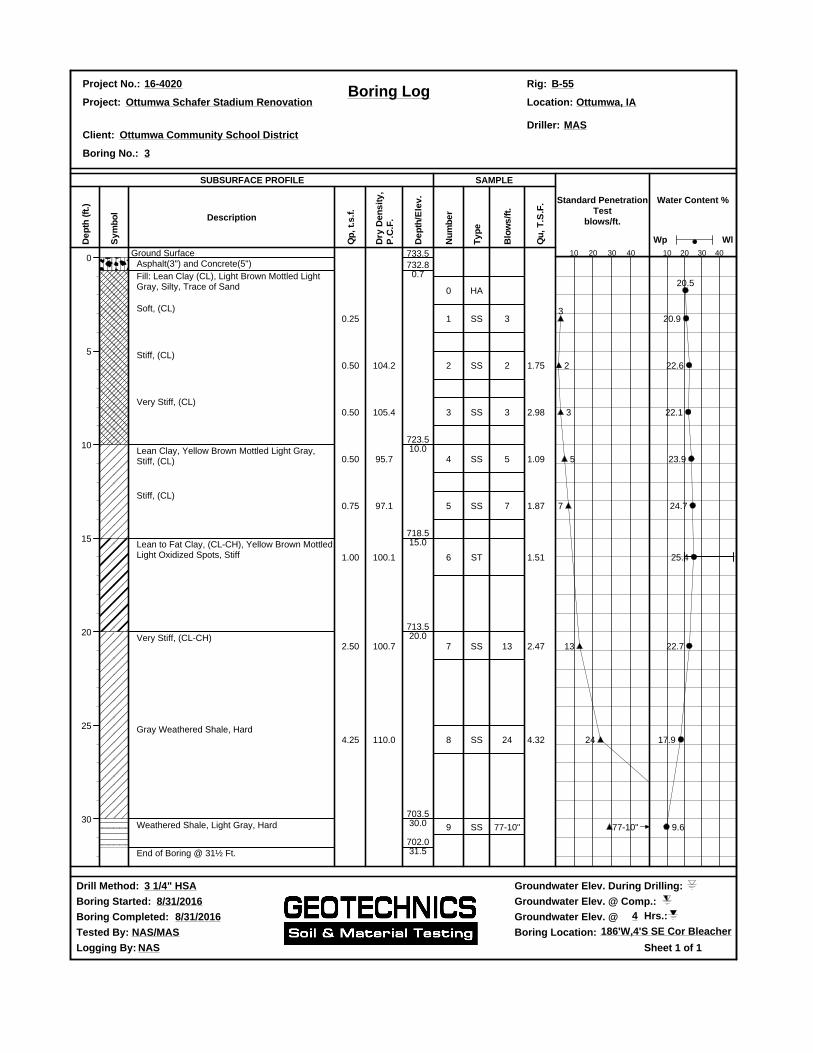
0
5
10
15
20
25
30
Ground SurfaceAsphalt(3") and Concrete(5")
Fill: Lean Clay (CL), Light Brown Mottled LightGray, Silty, Trace of Sand
Soft, (CL)
Stiff, (CL)
Very Stiff, (CL)
Lean Clay, Yellow Brown Mottled Light Gray,Stiff, (CL)
Stiff, (CL)
Lean to Fat Clay, (CL-CH), Yellow Brown MottledLight Oxidized Spots, Stiff
Very Stiff, (CL-CH)
Gray Weathered Shale, Hard
Weathered Shale, Light Gray, Hard
End of Boring @ 31½ Ft.
0.25
0.50
0.50
0.50
0.75
1.00
2.50
4.25
104.2
105.4
95.7
97.1
100.1
100.7
110.0
732.80.7
723.510.0
718.515.0
713.520.0
703.530.0
702.031.5
0
1
2
3
4
5
6
7
8
9
HA
SS
SS
SS
SS
SS
ST
SS
SS
SS
3
2
3
5
7
13
24
77-10"
1.75
2.98
1.09
1.87
1.51
2.47
4.32
3
2
3
5
7
13
24
77-10"
20.5
20.9
22.6
22.1
23.9
24.7
25.4
22.7
17.9
9.6
Project No.: 16-4020 Rig: B-55Boring Log
Project: Ottumwa Schafer Stadium Renovation Location: Ottumwa, IA
Driller: MASClient: Ottumwa Community School District
Boring No.: 3
Drill Method: 3 1/4" HSA Groundwater Elev. During Drilling:
Boring Started: 8/31/2016 Groundwater Elev. @ Comp.:
Boring Completed: 8/31/2016 Groundwater Elev. @ 4 Hrs.:
Tested By: NAS/MAS Boring Location: 186'W,4'S SE Cor Bleacher
Logging By: NAS
De
pth
(ft
.)
SUBSURFACE PROFILE
Sy
mb
ol
Description
Qp
, t.
s.f
.
Dry
De
ns
ity
,P
.C.F
.
De
pth
/Ele
v.
Nu
mb
er
SAMPLE
Ty
pe
Blo
ws
/ft.
Qu
, T
.S.F
. Standard PenetrationTest
blows/ft.
10 20 30 40
Water Content %
10 20 30 40
Wp Wl
733.5
Sheet 1 of 1

This Page Left Blank Intentionally
Ottumwa Community School District Project No. 16-4020 Ottumwa Schafer Stadium Concourse Upgrades March 2018 Ottumwa, IA
RETURN WITH BID
004200 - 1 004200-000 Bid Proposal.doc
SECTION 004200 BID PROPOSAL
TO: OTTUMWA COMMUNITY SCHOOL DISTRICT, Hereinafter Called "OWNER"
PROPOSAL OF: (Name and Address of Bidder)
FOR: OTTUMWA SCHAFER STADIUM UPGRADES
1. The plans for the proposed improvement are those prepared by KLINGNER & ASSOCIATES, P.C.; 604 Liberty St., Suite 125, Pella, Iowa 50219, which plans are designated as:
OTTUMWA SCHAFER STADIUM CONCOURSE UPGRADES
2. In submitting this proposal, the undersigned declares that the only persons or parties interested in the proposal as principals are those named herein; and that the proposal is made without collusion with any other person, firm, or corporation.
3. The undersigned further declares that the Bidding and Contract Documents, and the following Addenda, receipt of all which is hereby acknowledged have been carefully examined, the site(s) of the proposed work inspected in detail and the undersigned is familiar with all local conditions affecting the contract and the detailed requirements of construction, and understands that in making this proposal waives all right to plead any misunderstanding regarding the same.
4. Bidder acknowledges receipt of the following Addenda:
Addendum No. Addendum Date
5. The undersigned further understands and agrees, if this proposal is accepted, to furnish and provide all necessary machinery, tools, apparatus and other means of construction, and to do all of the work and to install all of the materials specified in the contract, in the manner and at the time prescribed, and in accordance with the requirements therein set forth.
6. The undersigned further understands and agrees that payment will be made on a LUMP SUM bid basis for the work specified herein.
7. The undersigned further agrees to the fullest extent permitted by law, to waive any claim it has or may have against the OWNER, the Architect/Engineer, and their respective employees, arising out of or in connection with the administration, evaluation, or recommendation of any bid; wavier of any requirements under the Bid Documents; or the Contract Documents; acceptance or rejection of any bids; and award of the Contract.
8. The undersigned further agrees that the OWNER may at any time during the progress of the work covered by this contract order other work or materials incidental thereto and that all such work and materials as do not appear in the proposal or contract as a specific item and which are not included under the bid price for other items in this contract, shall be performed as extra work, in accordance with ARTICLE 7 of the General Conditions.

Ottumwa Community School District Project No. 16-4020 Ottumwa Schafer Stadium Concourse Upgrades March 2018 Ottumwa, IA
RETURN WITH BID
004200 - 2 004200-000 Bid Proposal.doc
9. The undersigned further agrees to execute a contract for this work and present the same to the OWNER within fifteen (15) days after the date of notice of the award of the contract to him.
10. The undersigned further agrees to execute and present within fifteen (15) days after the date of Notice of the Award, a performance and payment Bond or other specified Security, satisfactory to and in the form prescribed by the OWNER, in the penal sum of the full amount of the contract, guaranteeing the faithful performance of the work in accordance with the terms of the contract.
11. The undersigned further agrees to begin work not later than ten (10) days after the execution and approval of the contract and performance and payment Bonds or specified Securities, unless otherwise provided, and to prosecute the work in such manner and with sufficient materials, equipment, and labor as will insure its completion within the time limit specified herein, it being understood and agreed that the completion within the time limit is an essential part of the contract. The undersigned agrees to work within the work schedule as defined in Article 17 of Section 002113 “Owner’s Instructions to Bidders/Contractors”. In case of failure to complete the work within the time named herein or within such extra time as may have been allowed by extensions, the undersigned agrees that the OWNER shall withhold, from such sums as may be due under the terms of this contract, the costs set forth in the specifications, which costs shall be considered and treated not as a penalty but as damages due the OWNER from the undersigned by reason of inconvenience to the public, added cost of engineering, and other items which have caused an expenditure of public funds resulting from the failure of the undersigned to complete the work within the time specified in the contract. Work shall include liquidated damages as defined in Article 34 of Section 002113 “Owner’s Instructions to Bidder/Contractor”.
12. Accompanying this proposal is a bid bond, bank cashier's check, or certified check, in the penal sum of five percent (5%) of the total bid price, as provided in the Section titled “Bid Security” in the Instructions to Bidders, made payable to the OTTUMWA COMMUNITY SCHOOL DISTRICT The amount of the bid deposit is:
$__________________________________________________DOLLARS ($________________) Words Figures
If this proposal is accepted and the undersigned shall fail to execute a contract and performance and payment Bond or specified Security, as required herein, it is hereby agreed that the amount of the bid deposit shall become the property of the OWNER,, and shall be considered as payment of damages due to delay and other causes suffered by the OWNER because of the failure to execute said contract and contract securities, otherwise said check or draft, or bidder's bond substituted in lieu thereof shall be returned to the undersigned.
ATTACH BANK CASHIER'S CHECK, OR
CERTIFIED CHECK HERE - OR INCLUDE BID BOND WITHIN PROPOSAL
FORM

Ottumwa Community School District Project No. 16-4020 Ottumwa Schafer Stadium Concourse Upgrades March 2018 Ottumwa, IA
RETURN WITH BID
004200 - 3 004200-000 Bid Proposal.doc
BASE BID
NOTE: All work as shown on drawings and as specified herein shall be awarded to one single Contractor: refer to Article 8 of Section 002113 “Owner’s Instructions To Bidders/Contractors”.
13. Base Bid – Concourse Upgrades as shown and specified:
Provide for the sum of:__________________________________________________________
______________________________________________Dollars ($_______________________)

Ottumwa Community School District Project No. 16-4020 Ottumwa Schafer Stadium Concourse Upgrades March 2018 Ottumwa, IA
RETURN WITH BID
004200 - 4 004200-000 Bid Proposal.doc
BIDDING SIGNATURE
(If an individual) Signature of Bidder (SEAL) Business Address
(If a co-partnership) Firm Name Signed by (SEAL) Business Address (Insert Names and Addresses of all Members of the Co-Partnership
(If a Corporation) Corporate Name (Corporate Signed by (SEAL) Business Address (Insert Names of President Officers) Secretary Treasurer
SIGNED and SWORN to before me this day of , 20 . (NOTARY SEAL) Notary Public END OF SECTION 004200

Ottumwa Community School District Project No. 16-4020 Ottumwa Schafer Stadium Concourse Upgrades March 2018 Ottumwa, IA
RETURN WITH BID
004313 - 1 004313-000 Bid Security Form.doc
SECTION 004313 BID SECURITY FORM
Project: OTTUMWA SCHAFER STADIUM CONCOURSE UPGRADES
WE
as PRINCIPAL, and
as SURETY, are held and firmly bound unto the OTTUMWA COMMUNITY SCHOOL DISTRICT hereinafter called “Owner” in the penal sum of 5% of the total bid price, or for the amount specified in the "Bid Proposal" in effect on the date of invitation for bids. We bind ourselves, our heirs, executors, administrators, successors, and assigns, jointly to pay to the Owner this sum under the conditions of this instrument.
WHEREAS THE CONDITION OF THE FOREGOING OBLIGATION IS SUCH that, said PRINCIPAL is submitting a written proposal to the Owner for the construction of the work designated as the above section.
THEREFORE, if the proposal is accepted and a contract awarded to the PRINCIPAL by the Owner for the above-designated project, and the PRINCIPAL shall within fifteen (15) days after award enter into a formal contract, furnish surety or cash bond guaranteeing the faithful performance of the work, and furnish evidence of the required insurance coverage, all as provided in the "General Conditions" and applicable Supplemental Conditions, then this obligation shall become void; otherwise it shall remain in full force and effect.
IN THE EVENT the Owner determines the PRINCIPAL has failed to enter into a formal contract in compliance with any requirements set forth in the preceding paragraph, then the Owner shall immediately be entitled to recover the full penal sum set out above together with all court costs, all attorney fees, and any other expense of recovery.
IN TESTIMONY WHEREOF, the said PRINCIPAL and the said SURETY have caused this instrument to be signed by their respective officers and their corporate seals to be hereunto affixed this day of AD, 20 .
PRINCIPAL
(Company Name) (Company Name)
By: By: (Signature & Title) (Signature & Title)
(if PRINCIPAL is a joint venture of two or more contractors, the company names, seals and authorized signatures of each contractor must be affixed.)
SURETY
By: (Name of Surety) (Signature of Attorney-in-Fact)
STATE OF ,
COUNTY OF

Ottumwa Community School District Project No. 16-4020 Ottumwa Schafer Stadium Concourse Upgrades March 2018 Ottumwa, IA
RETURN WITH BID
004313 - 2 004313-000 Bid Security Form.doc
I, , a Notary Public in and for said County, do hereby
certify that
(Insert names of individuals signing on behalf of PRINCIPAL & SURETY)
who are each personally known to me to be the same persons whose names are subscribed to the foregoing instrument on behalf of PRINCIPAL and SURETY, appeared before me this day in person and acknowledged respectively, that they signed, sealed, and delivered said instrument as their free and voluntary act for the uses and purposes therein set forth.
Given under my hand and notarial seal this day of A.D. 20 .
My Commission expires
Notary Public END OF SECTION 004313

Ottumwa Community School District Project No. 16-4020 Ottumwa Schafer Stadium Concourse Upgrades March 2018 Ottumwa, IA
004325 - 1 004325 Proposed Equivalent Product Request Form.docx 06/22/15
SECTION 004325 PROPOSED EQUIVALENT PRODUCT REQUEST FORM
TO: Klingner & Associates, P.C.
Project: Ottumwa Schafer Stadium Concourse Upgrades We hereby submit for your consideration the following product instead of the specified item for the above project:
Section Paragraph Specified Item
Proposed Equivalent Product:
Attach complete technical data including laboratory test if applicable. Include complete information changes to Drawings and/or Specifications which proposed equivalent product require for proper installation. Fill in blanks below, use additional sheets if necessary:
A. Does the proposed equivalent product affect dimensions shown on Drawings?
B. Will the undersigned pay for changes to building design, including engineering and detailing costs caused by proposed equivalent product, if any?
C. What effect does proposed equivalent product have on other trades?
D. Differences between proposed equivalent product and specified item?
E. Manufacturer’s guarantees of proposed and specified items are:
Same Different (explain on attachment)
The undersigned states that the function, appearance and quality are equivalent or superior to the specified item.
Submitted by: For use by Design Consultant Signature Accepted Accepted as Noted Not Accepted Received to Late Firm By Address Date Remarks Telephone
END OF SECTION 004325

This Page Left Blank Intentionally
Ottumwa Community School District Project No. 16-4020 Ottumwa Schafer Stadium Concourse Upgrades March 2018 Ottumwa, IA
004336 - 1 004336-000 Proposed Subcontractors Form.doc
SECTION 004336 PROPOSED SUBCONTRACTORS FORM
TO: BOARD OF EDUCATION, OTTUMWA COMMUNITY SCHOOL DISTRICT, hereinafter called "Owner".
1. Pursuant to bidding requirements for the Work Titled: OTTUMWA SCHAFER STADIUM CONCOURSE UPGRADES for portions of the Work equaling or exceeding 1/2 of 1% of the total proposed Contract sum the undersigned proposes to use the following subcontractors. Except as otherwise approved by the Owner, the undersigned proposes to perform all other Work with his (her) own forces. Deliver listing of subcontractors and suppliers to Engineer / Architect no later than one (1) hour after Bids are received. Listing shall be faxed to E/A at 319.752.3605 or delivered in person to the owner. Pursuant to bidding requirements for the Work Titled:
2. PORTION OF THE WORK: SUBCONTRACTOR NAME AND ADDRESS:
USE ADDITIONAL SHEETS IF REQUIRED Provide Signature BIDDER: Identical to that shown on Bid Form
by:
END OF SECTION 004336

This Page Left Blank Intentionally

Ottumwa Community School District Project No. 16-4020 Ottumwa Schafer Stadium Concourse Upgrades March 2018 Ottumwa, IA
005100 - 1
SECTION 005100 NOTICE OF AWARD
Dated
TO: (Bidder)
ADDRESS:
Contract: OTTUMWA COMMUNITY SCHOOL DISTRICT
Project: OTTUMWA SCHAFER STADIUM CONCOURSE UPGRADES
OWNER’s Contract No. 16-4020
You are notified that your Bid dated for the above Contract has been considered. You are the apparent Successful Bidder and have been awarded a contract for:
(Indicate total Work, alternates or sections of Work awarded)
The Contract Price of your contract is
Dollars ($ )
Four (4) copies of each of the proposed Contract Documents (except Drawings) accompany this Notice of Award. Two (2) Sets of the Drawings will be delivered separately or otherwise made available to you immediately.
You must comply with the following conditions precedent within ten days of this Notice of Award, that is by , 2018. 1. You must deliver to the OWNER Three (3) fully executed counterparts of the Contract Documents.
2. Deliver with the executed Contract Documents the Contract security (Bonds) as specified in the Instructions to Bidders, General Conditions and Supplementary Conditions.

Ottumwa Community School District Project No. 16-4020 Ottumwa Schafer Stadium Concourse Upgrades March 2018 Ottumwa, IA
005100 - 2
3. (List other conditions precedents).
Failure to comply with these conditions within the time specified will entitle OWNER to consider your Bid in default, to annul this Notice of Award and to declare your Bid Security forfeited. Within ten days after you comply with the above conditions, OWNER will return to you one fully signed counterpart of the Contract Documents.
OTTUMWA COMMUNITY SCHOOL DISTRICT (OWNER) By: (AUTHORIZED SIGNATURE) Owner’s Representative (TITLE)
Copy to ENGINEER/ARCHITECT (Use Certified Mail, Return Receipt Requested) END OF SECTION 005100


This Page Left Blank Intentionally

Ottumwa Community School District Project No. 16-4020 Ottumwa Schafer Stadium Concourse Upgrades March 2018 Ottumwa, IA
005500 - 1
SECTION 005500 NOTICE TO PROCEED
Dated
TO: (CONTRACTOR)
ADDRESS:
Contract: OTTUMWA COMMUNITY SCHOOL DISTRICT
Project: OTTUMWA SCHAFER STADIUM CONCOURSE UPGRADES
OWNER’S CONTRACT NO: 16-4020
OTTUMWA SCHAFER STADIUM CONCOURSE UPGRADES
You are notified that the Contract Time under the above contract will commence to run on , 2018. By that date, you are to start performing your obligations under the Contract Documents. In accordance with Article 4 of the Agreement the date of Completion is and the date of readiness for final payment is . Before you may start any Work at the Site, paragraph 2.05.C of the General Conditions provides that you and the Owner must each deliver to the other (with copies to the Engineer/Architect and other identified additional insured’s) certificates of insurance which each is required to be purchased and maintained in accordance with the Contract Documents. Also before you may start any Work at the site, you must: (add other requirements) Inform the Owner and Architect of Construction Schedule. Attend a pre-construction meeting with Owner and Architect.
Ottumwa Community School District (OWNER) By: (AUTHORIZED SIGNATURE) Owner’s Representative (TITLE)
Copy to Engineer/Architect
1 (Use Certified Mail, Return Receipt Requested)
END OF SECTION 005500

This Page Left Blank Intentionally

Ottumwa Community School District Project No. 16-4020 Ottumwa Schafer Stadium Concourse Upgrades March 2018 Ottumwa, IA
006113 - 1 006113-000 Performance & Payment Bond.doc May 2016
SECTION 006113 PERFORMANCE AND PAYMENT BOND
KNOW ALL BY THESE PRESENTS:
That we of
hereinafter called PRINCIPAL, and of
hereinafter called the SURETY,
are held and firmly bound unto BOARD OF EDUCATION, OTTUMWA COMMUNITY SCHOOL DISTRICT, hereinafter called OWNER, and unto all persons, firms, and corporations who may furnish materials for, or perform labor on the OTTUMWA SCHAFER STADIUM CONCOURSE UPGRADES, dated MARCH 2018, hereinafter referred to, in the penal sum of DOLLARS
____________________ CENTS ($______________) in lawful money of the United States, for the payment of which sum well and truly to be made, we bind ourselves, our heirs, executors, administrators and successors, jointly and severally firmly by these presents. THE CONDITION OF THIS OBLIGATION IS SUCH, that whereas the Principal entered into a certain contract, dated 2018 with the BOARD OF EDUCATION, OTTUMWA COMMUNITY SCHOOL DISTRICT, the OWNER, a copy of which is attached and hereby is referred to and made a part hereof, as if written herein at length, and whereby the said Principal has promised and agreed to perform said work in accordance with the terms of said contract, and has promised to pay all sums of money due for labor, materials, apparatus, fixtures, or machinery furnished to such Principal for the purpose of performing such work and has further agreed to pay all direct and indirect damages to any person, firm, company, or corporation suffered or sustained on account of the performance of such work during the time thereof and until such work is completed and accepted, and has further agreed that this bond shall inure to the benefit of any person, firm, company or corporation, to whom any money may be due from the Principal, subcontractor or otherwise, for any such labor, materials, apparatus, fixtures or machinery so furnished and that suit may be maintained on such bond by any such person, firm, company, or corporation, for the recovery of any such money. NOW THEREFORE, if the said Principal shall well and truly perform said work in accordance with the terms of said contract, and shall pay all sums of money due or to become due for any labor, materials, apparatus, fixtures or machinery furnished to him for the purpose of constructing such work, and shall commence and complete the work within the time prescribed in said contract, and shall pay and discharge all damages, direct and indirect, that may be suffered or sustained on account of said work during the time of the performance thereof and until the said work shall have been accepted, and shall hold the aforesaid Owner and its or his agents harmless on account of any such damages, and shall in all respects fully and faithfully comply with all the provisions, conditions, and requirements of said contract, then this obligation to be void; otherwise to remain in full force and effect.

Ottumwa Community School District Project No. 16-4020 Ottumwa Schafer Stadium Concourse Upgrades March 2018 Ottumwa, IA
006113 - 2 006113-000 Performance & Payment Bond.doc May 2016
IN WITNESS WHEREOF, this instrument is executed this day of A.D. 2018.
In the presence of: Principal (Address)
By:
ATTEST:
SURETY:
By: Attorney-in-Fact
ATTEST:
STATE OF
COUNTY OF
On this day of 2018 before me personally appeared
Principal, and
Surety,
all personally known to me to be the persons described in and who executed the above bond, and severally and individually acknowledged to me that they executed the same.
Given under my hand and notary seal, this day of A.D., 2018.
Notary Public
My commission expires
NOTE: DATE OF BOND MUST NOT BE PRIOR TO DATE OF CONTRACT
NOTE: THE STANDARD “AIA” PERFORMANCE AND PAYMENT BOND IS AN ACCEPTABLE BOND FORMAT.
END OF SECTION 006113

Ottumwa Community School District Project No. 16-4020 Ottumwa Schafer Stadium Concourse Upgrades March 2018 Ottumwa, IA
007200 - 1 007200-090 General Conditions.doc March 23, 2016
SECTION 007200 GENERAL CONDITIONS
PART 1 - GENERAL
1.1 SUMMARY
A. AIA A201 - General Conditions of the Contract for Construction is the General Conditions of the Contract.
B. A copy of this document is included herein
END OF SECTION 007200

This Page Left Blank Intentionally


Ottumwa Community School District Project No. 16-4020 Ottumwa Schafer Stadium Concourse Upgrades March 2018 Ottumwa, IA
007300 - 1 007300-090 Supplementary Conditions.doc
SECTION 007300 SUPPLEMENTARY CONDITIONS
1. PRECEDENCE OF SUPPLEMENTARY GENERAL CONDITIONS
The General Conditions are defined in AIA Document A201. These Supplementary General Conditions take precedence over the GENERAL CONDITIONS OF THE CONTRACT FOR CONSTRUCTION, AIA Document A201, as hereinafter stated.
2. MODIFICATIONS DELETIONS AND ADDITIONS
The following supplements modify, change, delete or add to the AIA General Conditions, A201-2007 Edition. Where any part of the General Conditions is modified or voided by these Articles, the unaltered provisions of that part shall remain in effect.
3. DEFINITION OF TERMS - Where used in any of the Contract Documents, the following meaning will be given to terms herein defined.
A. Contract/Agreement - Standard Form of Agreement between Contractor and Owner for the Construction of Buildings, AIA Form A101, current edition.
B. Contractor - The term "Contractor", as used in the Contract Documents, shall refer to the Person or Firm named in the Contract/Agreement for the specific work involved. Only one contractor is recognized as a party to the contract. His is the sole responsibility for the proper execution of the work stated in the Contract/Agreement.
C. General Contractor - The term "General Contractor" shall mean the Contractor for Complete Construction, or the Contractor for General Construction Work (where no Contractor for Complete Construction is involved in the project).
D. The term "Product" includes materials, systems, and equipment.
E. The terms "Approved", "Required", "As Directed", etc. are interpreted and will be taken to mean "to the satisfaction of the Architect".
F. Where the word "Shall" appears it is to be interpreted to mean "Must - Mandatory".
G. The term "Similar" means in its general sense and not necessarily identical.
4. ARTICLE 1: GENERAL PROVISIONS
1.1 BASIC DEFINITIONS
1.1.1 Contract Documents
Delete the last sentence of this Paragraph and replace it with the following:
The Contract Documents also include the bidding requirements (Notice to Bidders and Instructions to Bidders). Unless specifically enumerated in the agreements the Contract Documents do not include sample forms and the Contractor’s Bid.
1.1.2.1 Add the following new language as Subparagraph 1.1.2.1:

Ottumwa Community School District Project No. 16-4020 Ottumwa Schafer Stadium Concourse Upgrades March 2018 Ottumwa, IA
007300 - 2 007300-090 Supplementary Conditions.doc
The Contract Documents shall be signed by the Owner and Contractor. If either the Owner or Contractor or both do not sign all the Contract Documents, the Architect shall identify such unsigned Documents. No Contract shall be formed between the parties until all Contract Documents are executed by both parties.
The Board of Education is the ultimate decision making authority and Board action may be required to authorize certain changes or alterations to the terms of the documents.
5. ARTICLE 2: OWNER
2.2 INFORMATION AND SERVICES REQUIRED BY THE OWNER
2.2.3. Add the following language to the end of this Paragraph: The Contractor shall compare information furnished by the Owner (with observable physical conditions) and the Contract Documents, and on the basis of such review, shall report to the Owner and Architect any conflicts, errors or omissions it discovers. Contractor shall be responsible for any additional costs, delays and damages resulting from the Contractor’s failure to immediately report any such errors, inconsistencies or omissions it discovers.
2.4 OWNER’S RIGHT TO CARRY OUT THE WORK.
Modify the next to the last sentence of this Paragraph to read:
“Such proposed action by Owner and amounts charged to the Contractor shall be reviewed by the Architect for any recommendations prior to implementation.”
Add the following language in sentence two, after the words “owner’s expenses” in Paragraph 2.4: “, including reasonable attorney’s fees,”
6. ARTICLE 3: CONTRACTOR
3.1 GENERAL 3.1.1 Add the following text to the end of this Paragraph:
Each Prime Contractor shall at the request of the Owner prior to execution of the Agreement and promptly from time to time as requested by the Owner thereafter furnish the Owner an update and current financial statement and/or Contractor Qualification Statement on AIA Document A305.
3.1.2.1 Add the following new Subparagraph:
The Contractor shall supervise and direct the Work in an excellent and workmanlike manner, complete the work and everything properly incidental thereto as stated in the Project Manual and Drawings or reasonably implied therefrom and otherwise in accordance with Contract Documents.
3.2.1 Add the following text to the end of this Paragraph:
In no case shall the Contractor proceed with any portion of the work in any uncertainty. The Contractor also represents that all Contract Documents for the Project have been

Ottumwa Community School District Project No. 16-4020 Ottumwa Schafer Stadium Concourse Upgrades March 2018 Ottumwa, IA
007300 - 3 007300-090 Supplementary Conditions.doc
examined; including those intended for work of trades not normally performed by the Contractor's own forces, and that it has become thoroughly familiar with all conditions which may pertain to or affect the Work under the Contract.
3.2.5 Add the following new Paragraph:
The Owner is entitled to reimbursement from the Contractor for amounts paid to the Architect for evaluating and responding to the Contractor’s requests for information where the requested information is available to the Contractor from a careful study and comparison of the Contract Documents, field conditions, other Owner-provided information, Contractor-prepared coordination drawings, or prior Project correspondence or documentation.
3.3 SUPERVISION AND CONSTRUCTION PROCEDURES
3.3.4 Add new Paragraph 3.3.4 as follows:
The Contractor acknowledges that it is the Contractor's responsibility to hire all personnel for the proper and diligent prosecution of the Work and the Contractor shall use its best efforts to maintain labor peace for the duration of the Project. In the event of a labor dispute, the Contractor shall not be entitled to any increase in the Contract Sum.
3.3.5 Add new Paragraph 3.3.5 as follows:
3.3.5 General Contractor shall be responsible for general coordination of all work, including mechanical and electrical portions, for proper scheduling of building operations. Each individual contractor shall cooperate fully with the General Contractor for proper scheduling and timely installation of all work under his contract and shall cooperate fully with other trades, contractors, and subcontractors employed on the project.
3.3.6 Add new Paragraph 3.3.6 as follows:
3.3.6 Contractor may authorize others to act for him in his absence, and shall maintain a competent superintendent on the job at all times whenever any prime or subcontract work is performed.
3.4 LABOR AND MATERIALS
3.4.1 Add the following language to the end of this Paragraph:
Work required by the Contract Document to be performed after working hours or work the Contractor elects to perform after hours shall be completed at no additional cost to the Owner.
3.4.3.1 Add a new Subparagraph 3.4.3.1 as follows:
The Contractor (Company) shall not be owned, operated, or managed by a registered sex offender who has been convicted of a sex offense against a minor in accordance with Iowa Code 692A.113. In addition, the Contractor shall not permit an employee, Subcontractor (Company) owned, operated, or managed by, or Subcontractor employee who is a registered sex offender convicted of a sex offense against a minor on real property of the schools of the Owner in accordance with Iowa Code 692A.113. The Contractor shall further acknowledge and certify services provided under this Contract

Ottumwa Community School District Project No. 16-4020 Ottumwa Schafer Stadium Concourse Upgrades March 2018 Ottumwa, IA
007300 - 4 007300-090 Supplementary Conditions.doc
comply with Iowa Code 692A.113, and shall fully execute and deliver copy of “Acknowledgement and Certification” with required insurance and bond documents upon Award of Contract.”
3.4.4 Add a new Paragraph 3.4.4 as follows:
By making requests for substitutions based on Subparagraph 3.4.2, the Contractor:
.1 represents that the Contractor has personally investigated the proposed substitute product and determined that it is equivalent or superior in all respects to that specified; .2 represents that the Contractor will provide the same warranty for the substitution that the Contractor would for that specified; .3 certifies that the cost data presented is complete and includes all related costs under this Contract except the Architect's redesign costs, and waives all claims for additional costs related to the substitution which subsequently becomes apparent; and; .4 will coordinate the installation of the accepted substitute, making such changes
as may be required for the Work to be complete in all respects.
3.5 WARRANTY 3.5. In the last sentence of this Paragraph add the words “or Owner” after the word “Architect”.
3.5.1 Add new Paragraph 3.5.1 as follows:
3.5.1 Contractor or his Sureties shall remedy any defects in the work and pay for all damages to other work resulting therefrom which may appear within a period of one year of the date of substantial completion as defined in the General Conditions. Neither the final certificate for payment nor the partial use by the Owner will relieve the Contractor or his Sureties of liability for faulty workmanship, faulty materials, or uncompleted work. All guarantee periods specified shall begin with the date of substantial completion and shall be submitted to Engineer/Architect together with all lien releases from all subcontractors and major material suppliers and with final lien release from prime contractor at time final payment application is made. This guarantee is not Owner's exclusive remedy but is in addition to any other rights or remedies of Owner.
3.6 TAXES 3.6 Delete Paragraph 3.6 in its entirety and add the following paragraphs:
3.6.1 Sales Taxes shall not be included in the bids. The Owner will apply for and distribute
exemption certificates and authorization letters to the Prime Contractors and Subcontractors as follows:
1. The Owner will complete an online application to register this Contract with the Iowa
Department of Revenue and Finance. The Owner will distribute tax exemption certificates and authorization letters to the Contractor and all subcontractors who have been identified at or before filing the Performance Bond. These tax exemption certificates and authorization letters are applicable only for the specific project under this Contract.
2. At or before the time the Performance Bond is filed, Contractor shall provide a listing to the Owner identifying all subcontractors. Contractor and subcontractors may make copies of the exemption certificate and shall provide, at the time of purchase, a copy of the tax exemption certificate to each supplier providing construction material for the
Ottumwa Community School District Project No. 16-4020 Ottumwa Schafer Stadium Concourse Upgrades March 2018 Ottumwa, IA
007300 - 5 007300-090 Supplementary Conditions.doc
Project. The Contractor or subcontractors may then purchase from the suppliers building materials for the project under this Contract free from sales tax.
3. Bidders shall be responsible for informing themselves of tax laws, requirements, regulations, and interpretations as they apply to this project.
3.6.2 The Contractor shall take note and comply with all governing laws, rules, and regulations
affecting the Work. This may include such laws, rules, and regulations as: Licensing of Contractors for special requirements, e.g. hazardous waste removal.
Requirements for special construction permits. Exemption from sales tax, if applicable. Wage rates and employment requirements when required by law or by Owner. Local labor requirements. Non-discriminatory hiring practices.
3.7 PERMITS, FEES, AND NOTICES, AND COMPLIANCE WITH LAWS
3.7.3 Modify Paragraph 3.7.3 to read as follows:
If the Contractor, or any of its Subcontractors or any Subcontractor, performs Work knowing it to be contrary to applicable laws, statutes, ordinances, codes, rules and regulations, or lawful orders of public authorities, the Contractor shall assume appropriate responsibility for such Work and shall bear the costs attributable to correction.
3.7.6 Add new Paragraph 3.7.6 as follows:
3.7.6 The General Contractor shall obtain and pay for Building Permit as may be required by local authorities. Each individual contractor shall obtain and pay for all other permits, licenses, franchises, and consents required by law or necessary to perform his portion of the work, and shall pay for all inspections required thereby.
3.7.7 Add the following new Paragraph 3.7.7 as follows:
3.7.7 The Contractor is responsible for scheduling inspections related to the
performance of its work and ensuring work is complete for inspections. Any costs associated with re-inspections caused by irregularities, deficiencies or non-conforming work will be borne by the responsible contractor including all Architectural and Engineering Services related to evaluation of the problem and development of an acceptable solution.
3.9 SUPERINTENDENT
3.9.1 Add the following language after the first sentence of this Paragraph: “, including work of the Contractor’s subcontractors. Any change in superintendent
personnel must be approved by the Owner.” Add the following language to the end of this Paragraph:
The approved Superintendent will work in this position until completion of the Work unless the Superintendent shall no longer be in the Contractor's employ, or shall be released at the request of the Architect and/or Owner.

Ottumwa Community School District Project No. 16-4020 Ottumwa Schafer Stadium Concourse Upgrades March 2018 Ottumwa, IA
007300 - 6 007300-090 Supplementary Conditions.doc
3.9.3.1 Add the following new Paragraph 3.9.3.1 as follows:
The Superintendent or Superintendents shall be thoroughly competent with full experience in all phases of the work to be performed under this Contract. The Superintendent or Superintendents proposed shall not have less than five (5) consecutive prior years’ experience in full charge of every type of work required herein and such experience shall be confirmed by submitted proof or satisfactory performance as may be directed by the Owner’s Representative. Anyone not deemed capable of directing all trades involved in the work shall be replaced or supplemented immediately upon request, by someone who is satisfactory. After a satisfactory Superintendent has been assigned, they shall not be withdrawn without the consent of the Architect and/or Owner.
3.10 CONTRACTOR’S CONSTRUCTION SCHEDULE
3.10.1 Modify Paragraph 3.10.1 to read as follows:
The Contractor, promptly after being awarded the Contract, shall prepare and submit for the Owner’s and Architect’s information a Contractor’s construction schedule for the Work. The schedule shall not exceed time limits current under the Contract Documents, shall be revised at appropriate intervals as required by the conditions of the Work and Project or as requested by the Owner or Architect, shall be related to the entire Project to the extent required by the Contract Documents, and shall provide for expeditious and practicable execution of the Work.
3.10.4 Add new paragraph 3.10.4 as follows:
3.10.4 The General Contractor shall submit within 15 days after award of contracts a proposed progress schedule for Engineer/Architect's approval. Schedule shall be in bar graph form and shall include all phases of the project construction and delivery dates of pertinent equipment and materials.
3.12 SHOP DRAWINGS, PRODUCT DATA, AND SAMPLES
3.12 Refer to paragraph 3.12 of the General Conditions, add:
3.12.11 Where shop drawings are noted or called for on specified items, it shall be the Contractors responsibility to receive the necessary documents, fabrication drawings, erection drawings, brochures, schedules, diagrams, etc. from the supplier or fabricator and to thoroughly check them for conformance with the requirements of the contract drawings and specifications.
3.12.12 Unless otherwise specified, a minimum of five (5) copies will be required and shall be forwarded to the Engineer/Architect for his review only after all details and dimensions have been verified by the Contractor. All copies must bear the approval stamp of the Contractor when they are submitted to Engineer/Architect for review. Engineer/Architect will promptly review and return the documents to the Contractor with corrections, comments and/or color and finish selections as may be required.
3.12.13 Any deviation in shop drawings from the requirements of the contract documents must be brought to Engineer/Architect's attention in writing at time shop drawings are submitted for his review. Judgment on acceptance of the deviation will be made between the Engineer/Architect and Owner when shop drawings are returned to the Contractor.
3.12.14 It shall be expressly understood the Engineer/Architect does not "approve" shop

Ottumwa Community School District Project No. 16-4020 Ottumwa Schafer Stadium Concourse Upgrades March 2018 Ottumwa, IA
007300 - 7 007300-090 Supplementary Conditions.doc
drawings. He (she) "reviews" shop drawings approved by the Contractor. Responsibility for approval of all shop drawings and other submittals rests fully with the Contractor.
3.13 USE OF SITE
3.13.1 Add the following new Paragraphs 3.13.1 and 3.13.2 as follows:
3.13.1 Contractors shall perform the Work so as to cause a minimum of inconvenience to and interruption of the Owner’s operations. Any and all interruptions of the operations of the Owner necessary for the performance of the Work shall be noted in the progress schedule and the Contractor shall additionally give the Owner sufficient advance notice of such interruption as to allow the Owner to adjust operations accordingly. Contractor’s failure to give the Owner timely notice of such intentions shall place the responsibility of any resulting delays or additional costs solely with the Contractor.
3.13.2 The Contractor shall not bring or permit any subcontractor, supplier or anyone else for
whom the Contractor is responsible, to bring on the site any asbestos, PCB's, petroleum, hazardous waste or radioactive materials (except for proper use in performing the Work).
3.15 CLEANING UP
3.15 Refer to paragraph 3.15 of the General Conditions, add:
3.15.3 General Housekeeping and Use of Premises - The General Contractor shall keep site of operations (building and/or site) free from the accumulation of waste materials and other debris at all times and see that all other contractors and subcontractors remove and dispose of their rubbish. If this cleanup is not carried out in a satisfactory manner, Owner reserves the right to contract separately for the removal of rubbish and to back charge the responsible Contractor or withhold portions of monthly payments until a satisfactory cleanup arrangement is made. All contractors are required to prevent trash from blowing on to adjoining properties.
3.15.4 All contractors shall store apparatus, materials, supplies, and equipment in such orderly fashion and in designated storage areas at the site of the work as will not unduly interfere with the progress of work of any other contractor.
3.15.5 Final Cleaning - Just prior to delivery of building and site to Owner, the General Contractor shall thoroughly clean the project area including: wash all windows, vacuum carpeting, clean floor tile, wipe off all fixtures and equipment, and provide clean filters for all air handling equipment. He shall also clean site of all debris and excess construction materials and equipment.
3.18: INDEMNIFICATION
3.18.1 Change Paragraph 3.18.1 to read as follows: To the fullest extent permitted by law, the Contractor shall indemnify and hold harmless
the Owner, Architect/Engineer, Architect/Engineer’s consultants, and agents and employees of any of them from and against any and all claims, damages, causes of action, losses and expenses, including but not limited the attorneys’ fees, arising out of or resulting from the performance of the Work by the Contractor, its subcontractors, agents or employees in the performance of any duties imposed by the contract or by law, provided that any such claim, damage, loss, or expense is attributable to bodily injury,

Ottumwa Community School District Project No. 16-4020 Ottumwa Schafer Stadium Concourse Upgrades March 2018 Ottumwa, IA
007300 - 8 007300-090 Supplementary Conditions.doc
sickness, disease, or death, or to injury to or destruction of tangible property, including the work itself and including the loss of use resulting therefrom, as is caused in whole or in part by the fault, negligent or intentional act or omission or breach of contract of the Contractor, a Subcontractor, or anyone directly or indirectly employed by any of them or anyone for whose acts they may be liable, regardless of whether or not such claim, damage, loss or expense is caused in part by a party indemnified hereunder. This specific indemnification by the Contractor is in addition to and not in lieu of other remedies which may be available to the Owner. Such obligation shall not be construed to negate, abridge or reduce other rights or obligations of indemnity which would otherwise exist as to a party or person described in this Section 3.18. In the event it shall become necessary for Owner to institute legal proceedings against the other party for recovery of any amounts due and owning under the Agreement, it is expressly agreed that if the Owner prevails in any such action it shall be entitled to recover from the non-prevailing party all costs, including reasonable attorney’s fees and all expert witness fees during pre-suit collection attempts, suit, and post judgment or settlement collection including those incurred on appeal.
7. ARTICLE 4: ARCHITECT
4.2.12 Modify Paragraph 4.2.12 to read as follows:
Interpretations and decisions of the Architect will be consistent with the intent of and reasonably inferable from, the Contract Documents and will be in writing or in the form of drawings. When making such interpretations and decisions, the Architect will endeavor to secure faithful performance by both Owner and Contractor and will not be liable for results of interpretations or decisions rendered in good faith.
4.12.15 Add new Paragraph 4.12.15 as follows:
4.2.15 Contractor shall refer all questions, notices, and requests for payment, proposals for change, and other matters concerning the work to the Engineer/Architect or his authorized representative.
8. ARTICLE 5: SUBCONTRACTORS
5.2.1 Modify Paragraph 5.2.1 to read as follows:
Unless otherwise stated in the Contract Documents or the bidding requirements, the Contractor, within 10 days after the award of the contract, shall furnish in writing to the Owner through the Architect the names of persons or entities (including those who are to furnish materials or equipment fabricated to a special design) proposed for each principal portion of the Work. The Architect may reply within 14 days to the Contractor in writing stating (1) whether the Owner or the Architect has reasonable objection to any such proposed person or entity or (2) that the Architect requires additional time for review. Failure of the Owner or Architect to reply within the 14-day period shall constitute notice of no reasonable objection.
9. ARTICLE 6: CONSTRUCTION BY OWNER OR BY SEPARATE CONTRACTORS
6.1.1 Add the following to the end of Paragraph 6.1.1 as follows:

Ottumwa Community School District Project No. 16-4020 Ottumwa Schafer Stadium Concourse Upgrades March 2018 Ottumwa, IA
007300 - 9 007300-090 Supplementary Conditions.doc
The Contractor shall give notification of the potential of a claim in writing to the Owner and/or Separate Contractor within forty-eight (48) hours of the occurrence or discovery of the potential of an occurrence of the delay or action that will result in making a claim.
10. ARTICLE 7: CHANGES IN THE WORK 7.1.1 Add the following the end of Paragraph 7.1.1 as follows: No claim for an addition to the maximum Contract sum shall be considered a valid claim
unless a written change order procedure is followed as outlined in this Article. Verbal authorization for changes must be supported by written approval before being considered valid. All Change Orders for amounts greater than $20,000 must be approved by either the School Superintendent or the School Board.
7.2 CHANGE ORDERS Add the following Subparagraph: 7.2.2 The forms used to process a Change Order will include AIA Document G701, Change
Order 7.3 CONSTRUCTION CHANGE DIRECTIVES
7.3.2 Add the following to the end of Paragraph 7.3.2 as follows:
,and upon prior written approval of the Owner 11. ARTICLE 8: TIME 8.1.2 Modify Paragraph 8.1.2 to read as follows:
The date of commencement of the Work is the date upon which the Owner issues a written Notice to Proceed
8.3 DELAYS AND EXTENSION OF TIME
Paragraph 8.3.1 shall be deleted and the following shall be inserted in lieu thereof: 8.3.1 If the Contractor is delayed at any time in progress of the Work by an act or neglect of the
Owner or Engineer/Architect, or of an employee of either, or of a separate contractor employed by the Owner, or by changes ordered in the Work, or by fire, unusual delay in deliveries, unavoidable casualties or other causes wholly beyond the Contractor’s or its Subcontractor’s suppliers’ controls and not reasonably anticipated, or by delay authorized by the Owner pending litigation, the Contract Time shall be extended by a Change order, for such reasonable time as the Owner or Engineer/Architect may determine. A time extension shall be Contractor’s sole remedy and compensation for all such delays. No compensation shall be given for such delays.
12. ARTICLE 9: PAYMENTS AND COMPLETION

Ottumwa Community School District Project No. 16-4020 Ottumwa Schafer Stadium Concourse Upgrades March 2018 Ottumwa, IA
007300 - 10 007300-090 Supplementary Conditions.doc
9.3 APPLICATION FOR PAYMENT
9.3.1 Modify Subparagraph 9.3.1 to read as follows
At least thirty (30) days before the date established for each progress payment, the General Contractor shall submit to the Architect an itemized Application for Payment for operations completed in accordance with the schedule of values, and must also provide Lien Waivers in connection with Application for Payment. Such application shall be notarized, if required, and supported by such data substantiating the Contractor's right to payment as the Owner or Architect may require, such as copies of requisitions from Subcontractors and material suppliers. If the Contract Documents required the Owner to retain a portion of the payments until some future time, the Applications for Payment shall clearly state the percentage and the amount to be retained. Once the Application is approved by the Architect, the Application for Payment must be submitted for approval to the Ottumwa Community School District Board of Directors at their next regularly scheduled meeting. The application must be received at the Board office at least one week prior to the scheduled meeting for it to be included in that meeting's scheduled business. The form of Application of Payment shall be AIA Document G702, APPLICATION AND CERTIFICATE FOR PAYMENT, supported by AIA Document G703, CONTINUATION SHEET. Forms shall be furnished by Contractor.
9.3.1.3 Add new subparagraphs:
9.3.1.3 Progress payments shall be made monthly upon application. Applications for Payment
shall clearly state the percentage and the amount to be retained. Once the Application is approved by the Architect, the Application for Payment will be submitted for approval to the Ottumwa Community School District Board of Directors for approval at their next regularly scheduled meeting. The application must be received at the Board office in accordance Board outlined procedures, as applicable; in order to be included in that meeting's scheduled business. Monthly estimates will be paid to the Contractor as the work progresses in amounts equal to ninety-five percent (95%) of the Contract value of the work completed during the preceding calendar month, including the actual cost of materials and equipment of a permanent nature to be incorporated in the work, and delivered to and stored at the job site. Such monthly payments shall in no way be construed as an act of acceptance for any part of the work, partially or totally completed. The Contractor shall submit a final application for payment of retainage at the conclusion of the Project. Final payment of the five percent (5%) due the Contractor will be paid not earlier than thirty-one (31) days from the date of final acceptance of the work by the Owner, and after receipt of satisfactory evidence that all claims pertaining to such Contract have been paid in full as approved in the Contract Documents for said work.
9.3.4 Add new Paragraph 9.3.4 as follows:
9.3.4 Contractor’s monthly estimate period for work performed shall be considered to begin on the 16th day of the month and end on the 15th day of the following month. Applications for monthly payments must be submitted to the architect by the 20th of the month. The architect will review and submit the pay application to the school district NLT the following 1st day of each month. Payment will then be approved at the regularly scheduled 1st Board Meeting of each month with payment to be made in the same week.

Ottumwa Community School District Project No. 16-4020 Ottumwa Schafer Stadium Concourse Upgrades March 2018 Ottumwa, IA
007300 - 11 007300-090 Supplementary Conditions.doc
9.3.5 Add new Paragraph 9.3.5 as follows:
9.3.5 Applications for payment shall be made on Application and Certificate for Payment form, AIA Document G702 with Continuation Sheets as necessary, AIA Document G703. In making such applications for payment, a retainage of 10% of the estimated amounts of completed work and stored materials shall be applied until the contract work has been completed.
9.5 DECISIONS TO WITHHOLD CERTIFICATION
9.5.1 Add the following to the list of items at the end of Paragraph 9.5.1:
.8 Service work not attended to. .9 Evidence of lack of careful workmanship. .10 Unworkmanlike or over expeditious construction. .11 Lack of attention to the special field duties specified. 9.5.3 Delete Paragraph 9.5.3 in its entirety.
9.6 PROGRESS PAYMENTS 9.6.4 Modify Paragraph 9.6.4 to read as follows: The Owner has the right to request written evidence from the Contractor that the
Contractor has properly paid Subcontractors and material and equipment suppliers amounts paid by the Owner to the Contractor for subcontracted Work. If the Contractor fails to furnish such evidence within seven days, the Owner shall have the right to contact Subcontractors to ascertain whether they have been properly paid. Regardless of any requests made pursuant to this section, neither the Owner nor Architect shall have an obligation to pay or to see to the payment of money to a Subcontractor, except as may otherwise be required by law.
9.6.8 Add new paragraph 9.6.8 as follows:
9.6.8 Progress payments will be made on a monthly basis. In making such partial payments for the work, 5% of the estimated amounts will be retained until the contract work has been completed.
9.6.9 Add a new Paragraph 9.6.9 which shall read as follows:
9.6.9 Payment to the Contractor will be made by the Owner from cash on hand from such sources as may be legally available.
9.8 SUBSTANTIAL COMPLETION 9.8.1 Add the following to the end of Paragraph 9.8.1:
, subject only to completion of minor punch list items, the absence of completion of which does not interfere with the Owner’s intended use of the Project.
Add new Subparagraph 9.8.4.1 as follows:
Ottumwa Community School District Project No. 16-4020 Ottumwa Schafer Stadium Concourse Upgrades March 2018 Ottumwa, IA
007300 - 12 007300-090 Supplementary Conditions.doc
9.8.4.1 The Prime Contractor shall reimburse the Owner for the Architect’s (including his consultants) additional services or attorney’s fees, if any, made necessary by the Contractor’s failure to finally complete the Work within sixty (60) days after the date specified in the Contract Documents for Substantial Completion, or subsequently modified by Change Order, or dates established in the Certificate of Substantial Completion. Reimbursement for these additional services will be deducted by the Owner from the amounts due the Contractor and paid directly to the Architect.
9.8.6 Add a new Paragraph 9.8.6 to read as follows:
Request for Early Release of Retainage Funds: Upon achieving Substantial Completion, as defined by Iowa Code Chapter 26, the Contractor may formally request the release of all or part of the retainage funds being held on the Project. The Contractors' request for Release of the Retainage Funds shall be accompanied by a sworn statement that ten (10) calendar days prior to filing the Request for Release of the Funds a notice was given to all known subcontractors, sub subcontractors and suppliers that the Contractor is requesting the early release of retainage funds. If proper documentation is received from the Contractor, the Owner will release all retainage funds at the next monthly Board meeting or within thirty (30) days, whichever is less, except it may retain the following:
1. An amount equal to 200% of the value of labor or materials yet to be provided on the Project as determined by the Owner and its authorized contract representative. For purposes of this section, "authorized contractor representative" means the Architect of Record on the Project, unless otherwise specified.
2. An amount equal to 200% of the value of any Chapter 573 claims currently on file at the time the Request for Release of Retainage is approved.
If the Owner withholds an amount from the retainage payment to the Contractor, the Owner will provide a reason the request is being denied to the Contractor within thirty (30) calendar days of the receipt of the request.
9.10 FINAL COMPLETION AND FINAL PAYMENT 9.10.2 In Paragraph 9.10.2 add the following:
Final application for payment will not be approved for payment by the Architect until the following list of documents, and any other as may be requested by the Owner or Architect, are provided to the Owner by the Contractor in a close-out document book consisting of a black, 3-ring binder with tabs for each category:
Final list of subcontractors. Executed roof guarantee. Completed maintenance status sheet. Contractor's statement of warranty. Executed original of occupancy permit. Punch list items completed and approved by Owner.
As-built redline drawings of the building, utilities, site, and appurtenances. Concrete material placement tests, taken during construction process. Contractor’s notarized affidavit that lien waivers submitted represent all labor and materials for which a lien can be filed (use AIA Form G706A).
Proper Sales and Use Tax Reports.
Add to the beginning of Paragraph 9.10.2 the following:

Ottumwa Community School District Project No. 16-4020 Ottumwa Schafer Stadium Concourse Upgrades March 2018 Ottumwa, IA
007300 - 13 007300-090 Supplementary Conditions.doc
9.10.2 No such partial or final payment will be due until the Contractor has certified to the Owner that the materials, labor and service involved in each Application for Payment have been paid for in accordance with the requirements stated in the Specifications.
9.10.2.1 Add new Subparagraph 9.10.2.1 to read as follows:
The Contractor shall provide Project Record Documents, Operation and Maintenance Manuals, Instruction of Owner’s personnel, Final Cleaning and other closeout procedures specified elsewhere.
Add new Paragraph 9.10.6 to read as follows:
9.10.6 Final payment will be made no earlier than 31 days following approval and final acceptance of the Project by the Ottumwa Community School District Board of Directors at a regularly scheduled Board Meeting, receipt of all Lien Waiver and/or Chapter 573 Claim Releases, Sales Tax information, and all other required closeout documents, and subject to the conditions of and in accordance with the provisions of Iowa Code Chapter 573 and Iowa Code Chapter 26. Owner may withhold from final payment any and all amounts required to reimburse the Owner for all costs, fees (including reasonable attorney’s fees) it incurred as a result of any Chapter 573 Claims filed on the project.
13. ARTICLE 10: SAFETY OF PERSONS AND PROPERTY
10.2.5.1 Add the following Sub-subparagraph 10.2.5.1 to read as follows:
Contractor’s required remedial actions for damage and loss to property referred to in Clauses 10.2.1.2 and 10.2.1.3 shall repair the damaged materials and surfaces to their original condition, or better, to the satisfaction of the Owner. All such repairs are the responsibility of the Contractor and shall be accomplished at no additional cost to the Owner.
10.2.8 Refer to paragraph 10.2 of the General Conditions, add:
10.2.8 Protections - Contractor shall be responsible for insuring that each particular subcontractor provides adequate shoring and bracing of all walls, structural frame and other building elements until all elements are secured with final connections and anchorage.
10.2.9 Add the following Paragraph 10.2.9 to read as follows:
At all times, protect the excavation, trenches and/or the buildings from damage or rain water, spring water, ground water, backing up of drains, or sewers, etc. Provide all pumps, equipment, and enclosures to give this protection.
Construct and maintain all necessary temporary drainage and do all pumping necessary to keep excavations free of water.
Provide all shoring, bracing, and sheeting as required for safety and for the proper execution of the Work. Remove when work is completed.
At the end of the day's work, all new work likely to be damaged shall be covered. During cold weather protect all work from damage. If low temperatures make it impossible to continue operations safely in spite of cold weather precautions, work shall cease after

Ottumwa Community School District Project No. 16-4020 Ottumwa Schafer Stadium Concourse Upgrades March 2018 Ottumwa, IA
007300 - 14 007300-090 Supplementary Conditions.doc
notifying Architect. All other protective measures not mentioned above which may be required shall be furnished by the particular contractor responsible for such protection.
10.3. HAZARDOUS MATERIALS
10.3.3 Delete this Paragraph in its entirety.
Add new subparagraphs:
10.3.7 All materials are specified and/or approved with the understanding and intent that they do not contain any known hazardous materials. Hazardous materials include, but are not limited to, asbestos, asbestos products, polychlorinated biphenyl (PCB) or other toxic substances.
10.3.8 Items not specifically specified, but utilized by the Contractors or their subcontractors in
the building process shall not contain such substances.
14. ARTICLE 11 – INSURANCE AND BONDS
11.1 Contractor’s Liability Insurance:
Add new Subparagraphs:
11.1.1.9 General Liability insurance shall include all major divisions of coverage and be on a comprehensive basis including:
1. Premises - Operations Liability. 2. Independent Contractors' and Owners' Protective Liability. 3. Products Including Completed Operations Liability. 4. Broad Form Property Damage, Including Completed Operations. 5. Contractual Liability (including indemnification obligations of the Contractor under
Paragraph 3.18 of Article 3 of the General Conditions). 6. Personal Injury Liability. 7. XCU Coverage. 8. Owned, Non-Owned and Hired Motor Vehicles. 9. Per project endorsement.
Add the following Subparagraphs to 11.1.2:
11.1.2.1 Each Prime Contractor shall obtain a $1,000,000 Combined Single Limit Policy with a $2,000,000 Aggregate for both General Liability and Automobile Liability including:
1. Workmen's Compensation: Statutory. 2. Employers' Liability: $1,000,000. 3. Independent Contractors: Same limits as above. 4. Products and Completed Operations: Same limits as above for two years commencing with issuance of final Certificate for Payment. 5. Umbrella Excess Liability Insurance: a. Provide an underlying $5,000,000 umbrella excess liability in excess of primary
limits.
11.1.2.2 All Contractors’ insurance policies shall name the Architect, his Agents and the Owner as additional insured.

Ottumwa Community School District Project No. 16-4020 Ottumwa Schafer Stadium Concourse Upgrades March 2018 Ottumwa, IA
007300 - 15 007300-090 Supplementary Conditions.doc
11.1.3 Add the following: Contractor shall not commence work, or allow any Subcontractor to
commence work until the required insurance has been obtained and submitted. Acceptance of the Certificate of Insurance by the Owner and Architect shall not relieve or decrease the liability of the Contractor hereunder.
Add new Subparagraph:
11.1.3.1 Furnish one copy of certificates herein required for each copy of Agreement; specifically
set forth evidence of coverage required by 11.1.1 and 11.1.2. The form of the certificate shall be AIA Document G705, or other generally accepted form. Furnish to the Owner and Engineer/Architect copies of any endorsements that are subsequently issued amending coverage or limits.
11.1.5 Add the following paragraphs:
11.1.5 Project insurance requirements set forth below shall govern where they are at variance with portions of Paragraph 11.1 of AIA General Conditions. Portions of Paragraph 11.1 that are not affected by the following shall remain in effect.
11.1.6 Contractor shall not commence work under this contract until he has obtained all
insurance required hereunder and such insurance has been approved by Owner.
11.1.7 A Certificate of Insurance, AIA Form G705 or ACORD Form 25S, complete in all respects, shall be filed with the Owner. Any certificate filed with the Owner which shall be found to be incomplete or not according to form will be returned as unsatisfactory.
11.1.8 Rejected Certificates of Insurance shall be corrected as necessary and
resubmitted until approved.
11.1.9 Each and every policy shall contain an endorsement stating that the insurance company will not, prior to completion of project or any policy of expiration date shown on policy and certificate, whichever occurs first, terminate policy or change any coverage therein without first mailing by registered mail written notice of such action at least thirty (30) days prior to termination or change to Owner at whose request policy and certificate are issued.
11.1.10 The Contractor shall purchase and maintain such insurance as will protect the
Contractor from claims set forth below which may arise out of or result from the Contractor’s operations under the contract, whether such operations be by the Contractor or by any subcontractor or by anyone directly or indirectly employed by any of them, or by anyone for whose acts any of them may be liable:
1. Claims under Workers’ Compensation, disability benefit, and other similar
employee benefit acts; 2. Claims for damages because of bodily injury, occupational sickness or
disease, or death of the Contractor’s employee; 3. Claims for damages because of bodily injury, sickness or disease, or
death of any person other than the Contractor’s employee. 11.1.10.1 The insurance to be maintained by Contractor shall be written as follows:
Worker’s Compensation and Employer’s Liability Insurance as prescribed by Iowa law minimum limits shown below covering Employer’s Liability: A. Bodily Injury by accident $500,000 each accident

Ottumwa Community School District Project No. 16-4020 Ottumwa Schafer Stadium Concourse Upgrades March 2018 Ottumwa, IA
007300 - 16 007300-090 Supplementary Conditions.doc
B. Bodily Injury by disease $500,000 each accident C. Bodily Injury by disease $500,000 policy limit
Commercial General Liability Insurance Combined Single Limits shown below covering Bodily Injury, Property Damage and Personal Injury: A. General Aggregate Limit $2,000,000 B. Products – Completed Operations
Aggregate Limit $2,000,000 C. Personal and Advertising Injury
Limit $1,000,000 D. Each Occurrence Limit $1,000,000 E. Fire Damage Limit (for any one fire) $ 50,000 F. Medical Damage Limit (any one person) $ 5,000 G. Umbrella/Excess Liability $5,000,000
Automobile Liability Insurance, covering all owned non-owned, hired and leased vehicles
with a minimum combined single limit for Bodily Injury and Property Damage of $1,000,000 per occurrence.
11.1.10.2 This Insurance must include the following features:
A. Coverage for all premises of operations, including portions of the work stored on site, stored off site and in transit. Portions of the work stored off site may be included in Applications for Payment subject to submittal of detailed material lists, value statements, and a certificate of insurance identifying the same as work covered on the owner’s behalf for this project. The policy shall be endorsed to provide the Aggregate Per Project Endorsement.
B. Person and Advertising injury. C. Operations by independent contractors. D. Contractual Liability coverage. E. Coverage for property damage underground or damaged by explosion or collapse
(XCU). F. Additional Insured: The Contractor shall include the Owner, Architect, and Architect’s
Consultants as additional insured on all policies except Worker’s Compensation. G. Insurance Certificates: Each policy noted above shall be issued by an insurance
company authorized to write such insurance in the State of Iowa and shall be reasonably acceptable to the Owner. These insurance policies shall not be canceled without at least 30 days prior written notice to the Owner. A properly executed Certificate of Insurance showing evidence of these insurance requirements shall be delivered to the Owner prior to the commencement of this project.
H. The company and the insured expressly agree and state that the purchase of this policy of insurance by the insured does not waive any of the defenses of governmental immunity available to the insured under Iowa Code Section 670.4 as it now exists and as it may be amended from time to time.
I. The company and the insured further agree that this policy of Insurance shall cover only those claims not subject to the defense of governmental immunity under Iowa Code Section 670.4 as it now exists and as it may be amended from time to time.
11.1.10.3 Subrogation: To the extent that such insurance is in force and collectible and to the extent
permitted by law, The Owner and Contractor each hereby releases and waives all right of recovery against the other or anyone claiming through or under each of them by way of subrogation or otherwise. The foregoing release and waiver shall apply to damage to contractor’s equipment, tools, and other personal property as well as automobiles.

Ottumwa Community School District Project No. 16-4020 Ottumwa Schafer Stadium Concourse Upgrades March 2018 Ottumwa, IA
007300 - 17 007300-090 Supplementary Conditions.doc
11.1.11 Contractor shall maintain Completed Operations and Products Insurance for a period of two (2) years after final acceptance of contract.
11.1.12 Coverage shall include endorsement for broad-form property damage, broad-form personal injury, and include multiple job site endorsement making the aggregate limit apply separately.
11.1.13 Contractor agrees to assist in reporting and investigation of any accident, and upon request shall cooperate with all interested insurance carriers in handling of any claim by securing and giving evidence and obtaining attendance of witness as required for any claim or suit.
11.1.14 Contractor is responsible for determining if subcontractors are to carry liability insurance. The Owner is not responsible for insurance on subcontractors.
11.1.15 Additional Insurance Provisions: Certificates of Insurance shall be filed with the Owner. If the Contractor fails to effect or maintain insurance as stated above, the Owner may insure his own interest and charge the cost thereof to the Contractor. If the Owner is damaged by failure of the Contractor to maintain such insurance or to so notify the Owner, he may recover damages against the Contractor. The Contractor shall furnish satisfactory proof that the insurance herein described has been authorized to do business in the State of Iowa. All certificates and/or policies of insurance furnished by the Contractor to be filed with the Owner and Architect shall include the name and address of the agency issuing the same. All certificates and/or policies shall be signed with an original signature. Signature stamps shall not be used.
11.3 PROPERTY INSURANCE 11.3.1 Modify the first sentence of Subparagraph 11.3.1 by deleting “Unless otherwise provided”. 11.3.1.1 Add the following to this Subparagraph: 11.3.1.1.1 The Contractor (and Subcontractors) shall be fully responsible for loss or damage to his
tools and equipment during the Construction process. Contractor (and Subcontractor) is responsible for loss or damage to materials and equipment prior to inclusion in the project. Contractor may at this option provide coverage for materials prior to installation.
11.3.1.3 Change this Subparagraph to read as follows: “In the event of a paid claim, the claimant shall be responsible for the deductible in the
amount of $1,000.00 per occurrence.” 11.4 PERFORMANCE BOND AND PAYMENT BOND Delete Paragraph 11.4.1 and substitute the following Paragraph and Subparagraphs: 11.4.1 Each Prime Contractor shall furnish bonds covering faithful performance of the contract
and payment of obligations arising thereunder. Bonds may be obtained through the Contractor’s usual source and the cost shall be included in the Contract sum. The amount of each bond shall be equivalent to 100 percent of the Contract sum.
11.4.1.1 Each Prime Contractor shall furnish the required bonds not later than fifteen days
following the date the Agreement is entered into, or if the work is to be commenced prior thereto in response to a letter of intent, the Contractor shall, prior to commencement of the work, submit evidence satisfactory to the Owner that such bonds will be furnished.

Ottumwa Community School District Project No. 16-4020 Ottumwa Schafer Stadium Concourse Upgrades March 2018 Ottumwa, IA
007300 - 18 007300-090 Supplementary Conditions.doc
11.4.1.2 The Contractor shall require the attorney-in-fact who executes the required bonds on behalf of the surety to affix thereto a certified and current copy of the power of attorney.
11.5 Performance Bond and Payment Bond
Simultaneously with this delivery of the executed contract, the Contractor shall furnish a Performance Bond and a Labor and Material Payment Bond executed on current AIA forms (A311). The penal sum for each shall be equal to 100 percent of the contract sum. The surety on such bonds shall be a duly authorized surety company authorized to do business in the State of Iowa and countersigned by an Iowa agency satisfactory to the Owner. The bidder surety shall affix thereto a certified and current copy of his power of attorney indicating the monetary limit of such power.
The amount of bond and protection to the Owner shall increase in the amount of any
changes made to the contract during the progress of the work.
15. ARTICLE 12: UNCOVERING AND CORRECTION OF WORK
12.2 CORRECTION OF WORK
12.2.2 AFTER SUBSTANTIAL COMPLETION Add the following language to the end of Paragraph 12.2.2.1
12.2.2.1 If the Contractor does not proceed with correction of such non-conforming Work within the time specified in Paragraph 2.4, the Owner may remove it and store savable materials or equipment at the Contractor’s expense.
16. ARTICLE 13: MISCELLANEOUS PROVISIONS 13.1 GOVERNING LAW
13.1.1 Amend this Paragraph to read as follows: The Contract shall be governed by the law of the State of Iowa.
13.1.2 Compliance with Law Provision:
The Contractor agrees that he will comply with all applicable Federal, State, and Local laws, statues, codes, rules, and regulations having jurisdiction over the project. Contractor shall take all necessary precautions to keep the site and work in compliance with the safety and health regulations for construction issued by the Bureau of Labor Standards of the U.S. Department of Labor as well as the Occupational Safety and Health Standards, parts 1910 and 1926 as amended and as enforced by the State of Iowa.
13.6 INTEREST
Amend this Paragraph to read as follows: Payments due and unpaid under the Contract Documents shall bear interest from the
date payment is due at the then current rate in effect pursuant to Iowa Code Section 573.14 or Iowa Code Section 74A.2, whichever is less.
13.7 Modify Paragraph 13.7 to read as follows:

Ottumwa Community School District Project No. 16-4020 Ottumwa Schafer Stadium Concourse Upgrades March 2018 Ottumwa, IA
007300 - 19 007300-090 Supplementary Conditions.doc
The Owner and Contractor shall commence all claims and causes of action, whether in contract, tort, breach of warranty or otherwise, against the other arising out of or related to the Contract in accordance with the requirements of the final dispute resolution method selected in the Agreement within the time period specified by applicable law, but in any case not more than 10 years after the date of Final Acceptance of the Work. The Owner and Contractor waive all claims and causes of action not commenced in accordance with this Section 13.7.
17. ARTICLE 14: TERMINATION OR SUSPENSION OF THE CONTRACT
14.2 TERMINATION BY THE OWNER FOR CAUSE
14.2.4 Modify Paragraph 14.2.4 to read as follows:
If the unpaid balance of the Contract Sum exceeds the costs of finishing the work, including compensation for the Architect’s services and expenses made necessary thereby, and other damages and expenses incurred by the Owner, including reasonable attorney’s fees, such excess shall be paid to the Contractor. If such costs and damages exceed the unpaid balance, the Contractor shall pay the difference to the Owner. The amount to be paid to the Contractor or Owner, as the case may be, shall be certified by the Initial Decision Maker, upon application, and this obligation for payment shall survive termination of the Contract.
18. ARTICLE 15: CLAIMS AND DISPUTES
15.1.6 Delete Paragraph 15.1.6 in its entirety. 15.2.6 Modify Paragraph 15.2.6 to read as follows:
The parties may file for mediation of an initial decision at any time, upon mutual agreement of the parties.
15.2.6.1Delete Paragraph 15.2.6.1 in its entirety.
15.2.8 Delete Paragraph 15.2.8 in its entirety.
15.3.1 Delete Paragraph 15.3.1 in its entirety.
15.3.2 Modify Paragraph 15.3.2 to read as follows:
The parties shall endeavor in good faith to resolve claims, disputes and other matters in question between them by mutual agreement and may, by mutual agreement and in their discretion, submit same to non-binding mediation (mediation) which shall be in accordance with Iowa Code Chapter 679C. Requests for mediation shall be given in writing to the other party to this Agreement. If the Owner and Contractor are unable to mutually agree upon a mediator in writing within sixty (60) days of receiving the written request for mediation, either party may then institute legal or equitable proceedings. Mediation shall be voluntary only and shall not be a prerequisite to litigation or other means of dispute resolution.
15.4 Delete Section 15.4, Arbitration, in its entirety.
Add the following New ARTICLES: 19. ARTICLE 16: EQUAL EMPLOYMENT OPPORTUNITY

Ottumwa Community School District Project No. 16-4020 Ottumwa Schafer Stadium Concourse Upgrades March 2018 Ottumwa, IA
007300 - 20 007300-090 Supplementary Conditions.doc
16.1 The Contractor shall conform in all respects with the provisions of the Federal Civil Rights Act, the Code of Iowa, Chapter 216 Civil Rights Commission and the rules and regulations adopted thereto by the Iowa Civil Rights Commission. The Contractor shall not discriminate against any employee or applicant because of race, creed, color, religion, sex, national origin, ancestry, age, marital status, parental status, sexual orientation, gender identity, genetic information, physical or mental disability, or any other protected class under state or federal law. The Contractor shall comply with all applicable federal, state and local, laws, rules, regulations, ordinances, policies and procedures, including the Ottumwa Community School District policies and procedures and the Iowa Smoke Free Air Act as outlined in Article 17. The Contractor shall require similar clauses in all of its subcontracts for service or materials.
20. ARTICLE 17: SMOKING AND RELATED ADVERTISING
17.1 Smoking will not be allowed on School property, which shall include inside private vehicles on school property. In addition, project workers shall not wear apparel that advertises tobacco or alcohol products or has profane language or images.
END OF SECTION 007300

Ottumwa Community School District Project No. 16-4020 Ottumwa Schafer Stadium Concourse Upgrades March 2018 Ottumwa, IA
008600 – 1 008600-000 Schedule of Drawings.doc
SECTION 008600 SCHEDULE OF DRAWINGS
The following list of Drawings (under separate cover) is herewith incorporated into this Project Manual in reference:
SHEET NUMBER AND TITLE:
G001 Cover Sheet C001 General Notes and Legends C101 Site Demolition and Site Plan C102 Grading and Erosion Control Plan C501 Site Details S001 Structural Notes S101 Structural Partial Plans S102 Structural Sections S103 Structural Elevations
END OF SECTION 008600

This Page Left Blank Intentionally

Ottumwa Community School District Project No. 16-4020 Ottumwa Schafer Stadium Concourse Upgrades March 2018 Ottumwa, IA
011000 - 1 011000-000 Summary of Work.doc February 2014
SECTION 011000 SUMMARY OF WORK
PART 1 - GENERAL
1.1 SUMMARY
A. This Section includes the following:
1. Work covered by the Contract Documents. 2. Sequence of Work. 3. Work under other contracts. 4. Use of premises. 5. Owner's occupancy requirements. 6. Specification formats and conventions.
1.2 WORK COVERED BY CONTRACT DOCUMENTS
A. Project Identification: OTTUMWA COMMUNITY SCHOOL DISTRICT OTTUMWA SCHAFER STADIUM CONCOURSE UPGRADES
1. Project Location: OTTUMWA SCHAFER STADIUM 1401 E. 4TH ST. OTTUMWA, IOWA 52501
B. Owner: BOARD OF EDUCATION OTTUMWA COMMUNITY SCHOOL DISTRICT
1. Owner's Representative: Chuck Bray, Director of Buildings and Grounds Ottumwa Community School District
C. Structural Engineer: Alan D. Lukens, P.E., S.E. Klingner & Associates, PC 604 Liberty Street, Suite 125 Pella, Iowa 50219
D. Civil Engineer: Curt S. Wavering, P.E. Klingner & Associates, PC 616 N 24th Street Quincy, IL 62301
E. The Work consists of the following:
1. The project consists in general of paving demolition and the paving of a new concourse including ramp repair, retaining wall improvements, fencing, and walkway lighting for the Ottumwa Schafer Stadium.
F. BASE BID work includes the following:
1. Concourse pavement demolition and replacement, and adding additional concourse area pavement.
2. East retaining wall concrete reinforcement and cap. 3. New chain link fence atop retaining wall.

Ottumwa Community School District Project No. 16-4020 Ottumwa Schafer Stadium Concourse Upgrades March 2018 Ottumwa, IA
011000 - 2 011000-000 Summary of Work.doc February 2014
4. Widen east walkway with new chain link fence and pathway lighting on north side of walkway.
5. Repair south ramp at top portion and bottom portion of ramp. 6. Modify and extend modular block retaining wall to expand concourse paving area south
of home side bleachers. 7. Stone retaining wall concrete reinforcement and cap. 8. Concrete cap over abandoned stairs beneath south ramp. 9. New 6 feet high chain link fence with new post mounting on south ramp. 10. Prime and paint existing ramp steel. 11. New retaining wall at southwest corner of home bleachers adjacent to new Pavilion Patio. 12. Owner to remove concessions building prior to concourse pavement demolition work.
G. Project will be constructed under one Base Bid.
1.3 SEQUENCE OF WORK
A. The Base Bid work shall be completed in the following order:
1. Base Bid: Work shall be completed per schedule.
B. Before commencing Work of Base Bid, submit a schedule showing the sequence, commencement and completion dates, and move-out and move-in dates of Owner's use of the site for all phases of the Work.
1.4 WORK UNDER OTHER CONTRACTS
1. General: All work shall be coordinated with the school district in order to have the least impact on the home football schedule and planned activities.
1.5 USE OF PREMISES
A. General: Contractor shall have limited use of premises for construction operations.
B. Use of Site: Limit use of premises to areas within the Contract limits. Do not disturb portions of Project site beyond areas in which the Work is indicated.
1. Limits: Coordinate construction operations with owner. 2. Owner Occupancy: Allow for coordinated Owner occupancy of Project site. 3. Driveways and Entrances: Coordinate usage with Owner.
a. Schedule deliveries to minimize use of driveways and entrances. b. Schedule deliveries to minimize space and time requirements for storage of
materials and equipment on-site.
C. Construction Schedule:
1. Access to site is to be available to start construction activities pending completed contract requirements.
2. All work schedules to be fully coordinated with Owner / Architect.

Ottumwa Community School District Project No. 16-4020 Ottumwa Schafer Stadium Concourse Upgrades March 2018 Ottumwa, IA
011000 - 3 011000-000 Summary of Work.doc February 2014
1.6 OWNER'S OCCUPANCY REQUIREMENTS
A. Coordinated Owner Occupancy: Owner may occupy site and existing adjacent buildings during the project construction with proper coordination of all contract work. Cooperate with Owner during construction operations to minimize conflicts and facilitate Owner usage. Perform the Work so as not to interfere with Owner's day-to-day operations. Maintain existing exits, unless otherwise indicated.
1. Maintain access to the site and other support buildings. Do not close or obstruct driveways, parking lots, and other support buildings without written permission from Owner and authorities having jurisdiction.
1.7 SPECIFICATION FORMATS AND CONVENTIONS
A. Specification Format: The Specifications are organized into Divisions and Sections using the 48-division format and CSI/CSC's "Master Format" numbering system.
1. Division 01: Sections in Division 01 govern the execution of the Work of all Sections in the Specifications.
B. Specification Content: The Specifications use certain conventions for the style of language and the intended meaning of certain terms, words, and phrases when used in particular situations. These conventions are as follows:
1. Abbreviated Language: Language used in the Specifications and other Contract Documents is abbreviated. Words and meanings shall be interpreted as appropriate. Words implied, but not stated, shall be inferred as the sense requires. Singular words shall be interpreted as plural and plural words shall be interpreted as singular where applicable as the context of the Contract Documents indicates.
2. Imperative mood and streamlined language are generally used in the Specifications. Requirements expressed in the imperative mood are to be performed by Contractor. Occasionally, the indicative or subjunctive mood may be used in the Section Text for clarity to describe responsibilities that must be fulfilled indirectly by Contractor or by others when so noted.
a. The words "shall," "shall be," or "shall comply with," depending on the context, are implied where a colon (:) is used within a sentence or phrase.
PART 2 - PRODUCTS (Not Used)
PART 3 - EXECUTION (Not Used)
END OF SECTION 011000

This Page Left Blank Intentionally

Ottumwa Community School District Project No. 16-4020 Ottumwa Schafer Stadium Concourse Upgrades March 2018 Ottumwa, IA
011419 - 1 011419-010 Use of Site.doc
SECTION 011419 USE OF SITE
PART 1 - GENERAL
1.1 SUMMARY
A. Work included: This Section applies to situations in which the Contractor or his representatives including, but not necessarily limited to, suppliers, subcontractors, employees, and field engineers, enter upon the Owner's property.
B. Related work:
1. Documents affecting work of this Section include, but are not necessarily limited to, General Conditions, Supplementary Conditions, and Sections in Division 1 of these Specifications.
1.2 QUALITY ASSURANCE
A. Promptly upon award of the Contract, notify all pertinent personnel regarding requirements of this Section.
B. Require that all personnel who will enter upon the Owner's property certify their awareness of and familiarity with the requirements of this Section.
1.3 TRANSPORTATION FACILITIES
A. Truck and equipment access:
1. To avoid traffic conflict with vehicles of the Owner's employees and students, and to avoid over-loading of streets and driveways elsewhere on the Owner's property, limit the access of trucks and equipment to the minimum required to complete the work.
B. Contractor's vehicles:
1. Require Contractor's vehicles, vehicles belonging to employees of the Contractor, and all other vehicles entering upon the Owner's property in performance of the Work of the Contract, to use only the designated Contractor’s Access Route.
2. Do not permit such vehicles to park on any street or other area of the Owner's property except as approved by Owner.
1.4 SECURITY
A. Restrict the access of all persons entering upon the Owner's property in connection with the Work to the Access Route and to the actual site of the Work.
END OF SECTION 011419

This Page Left Blank Intentionally

Ottumwa Community School District Project No. 16-4020 Ottumwa Schafer Stadium Concourse Upgrades March 2018 Ottumwa, IA
013100 - 1 013100-000 Project Management and Coordination.doc
SECTION 013100 PROJECT MANAGEMENT AND COORDINATION
PART 1 - GENERAL
1.1 SUMMARY
A. This Section includes administrative provisions for coordinating construction operations on Project including, but not limited to, the following:
1. Coordination Drawings. 2. Project meetings. 3. Requests for Interpretation (RFIs).
B. See Division 01 for procedures for coordinating general installation and field-engineering services, including establishment of benchmarks and control points.
1.2 SUBMITTALS
A. Coordination Drawings: Prepare Coordination Drawings if limited space availability necessitates maximum utilization of space for efficient installation of different components or if coordination is required for installation of products and materials fabricated by separate entities.
1. Content: Project-specific information, drawn accurately to scale. Do not base Coordination Drawings on reproductions of the Contract Documents or standard printed data. Include the following information, as applicable:
a. Indicate functional and spatial relationships of components of architectural, structural, civil, mechanical, and electrical systems.
b. Indicate dimensions shown on the Contract Drawings and make specific note of dimensions that appear to be in conflict with submitted equipment and minimum clearance requirements. Provide alternate sketches to Architect/Engineer for resolution of such conflicts. Minor dimension changes and difficult installations will not be considered changes to the Contract.
2. Sheet Size: At least 8½ by 11 inches but no larger than 30 by 40 inches 3. Format: Submit in pdf or dwg format. 4. Refer to individual Sections for Coordination Drawing requirements for Work in those
Sections.
1.3 DEFINITIONS
A. RFI: Request from Contractor seeking interpretation or clarification of the Contract Documents.
1.4 COORDINATION
A. Coordination: Coordinate construction operations included in different Sections of the Specifications to ensure efficient and orderly installation of each part of the Work. Coordinate

Ottumwa Community School District Project No. 16-4020 Ottumwa Schafer Stadium Concourse Upgrades March 2018 Ottumwa, IA
013100 - 2 013100-000 Project Management and Coordination.doc
construction operations, included in different Sections, which depend on each other for proper installation, connection, and operation.
1. Schedule construction operations in sequence required to obtain the best results where installation of one part of the Work depends on installation of other components, before or after its own installation.
2. Coordinate installation of different components with other contractors to ensure maximum accessibility for required maintenance, service, and repair.
3. Make adequate provisions to accommodate items scheduled for later installation. 4. Where availability of space is limited, coordinate installation of different components to
ensure maximum performance and accessibility for required maintenance, service, and repair of all components, including mechanical and electrical.
B. Prepare memoranda for distribution to each party involved, outlining special procedures required for coordination. Include such items as required notices, reports, and list of attendees at meetings.
1. Prepare similar memoranda for Owner and separate contractors if coordination of their Work is required.
C. Administrative Procedures: Coordinate scheduling and timing of required administrative procedures with other construction activities and activities of other contractors to avoid conflicts and to ensure orderly progress of the Work. Such administrative activities include, but are not limited to, the following:
1. Preparation of Contractor's Construction Schedule. 2. Preparation of the Schedule of Values. 3. Installation and removal of temporary facilities and controls. 4. Delivery and processing of submittals. 5. Progress meetings. 6. Preinstallation conferences. 7. Project closeout activities. 8. Startup and adjustment of systems. 9. Project closeout activities.
1.5 PROJECT MEETINGS
A. General: Schedule and conduct meetings and conferences at Project site, unless otherwise indicated.
1. Attendees: Inform participants and others involved, and individuals whose presence is required, of date and time of each meeting. Notify Owner and Architect/Engineer of scheduled meeting dates and times.
2. Agenda: Prepare the meeting agenda. Distribute the agenda to all invited attendees. 3. Minutes: Record significant discussions and agreements achieved. Distribute the
meeting minutes to everyone concerned, including Owner and Architect/Engineer, within seven days of the meeting.
B. Preconstruction Conference: Schedule a preconstruction conference before starting construction, at a time convenient to Owner and Architect/Engineer, but no later than 15 days after execution of the Agreement. Hold the conference at Project site or another convenient location. Conduct the meeting to review responsibilities and personnel assignments.

Ottumwa Community School District Project No. 16-4020 Ottumwa Schafer Stadium Concourse Upgrades March 2018 Ottumwa, IA
013100 - 3 013100-000 Project Management and Coordination.doc
1. Attendees: Authorized representatives of Owner, Architect/Engineer, and their consultants; Contractor and its superintendent; major subcontractors; suppliers; and other concerned parties shall attend the conference. All participants at the conference shall be familiar with Project and authorized to conclude matters relating to the Work.
2. Agenda: Discuss items of significance that could affect progress, including the following:
a. Tentative construction schedule. b. Sequence of Work. c. Critical work sequencing and long-lead items. d. Designation of key personnel and their duties. e. Procedures for processing field decisions and Change Orders. f. Procedures for RFIs. g. Procedures for testing and inspecting. h. Procedures for processing Applications for Payment. i. Distribution of the Contract Documents. j. Submittal procedures. k. Preparation of Record Documents. l. Use of the premises and existing building. m. Work restrictions. n. Owner's occupancy requirements. o. Responsibility for temporary facilities and controls. p. Construction waste management and recycling. q. Parking availability. r. Office, work, and storage areas. s. Equipment deliveries and priorities. t. First aid. u. Security. v. Progress cleaning. w. Working hours.
3. Minutes: Contractor will record and distribute meeting minutes.
C. Preinstallation Conferences: Conduct a Preinstallation Conference at Project site before each construction activity that requires coordination with other construction.
1. Attendees: Installer and representatives of manufacturers and fabricators involved in or affected by the installation and its coordination or integration with other materials and installations that have preceded or will follow, shall attend the meeting. Advise Architect/Engineer of scheduled meeting dates.
2. Agenda: Review progress of other construction activities and preparations for the particular activity under consideration, including requirements for the following:
a. The Contract Documents. b. Options. c. Related RFIs. d. Related Change Orders. e. Purchases. f. Deliveries. g. Submittals. h. Review of mockups. i. Possible conflicts. j. Compatibility problems. k. Time schedules. l. Weather limitations. m. Manufacturer's written recommendations.

Ottumwa Community School District Project No. 16-4020 Ottumwa Schafer Stadium Concourse Upgrades March 2018 Ottumwa, IA
013100 - 4 013100-000 Project Management and Coordination.doc
n. Warranty requirements. o. Compatibility of materials. p. Acceptability of substrates. q. Temporary facilities and controls. r. Space and access limitations. s. Regulations of authorities having jurisdiction. t. Testing and inspecting requirements. u. Installation procedures. v. Coordination with other work. w. Required performance results. x. Protection of adjacent work. y. Protection of construction and personnel.
3. Record significant conference discussions, agreements, and disagreements, including required corrective measures and actions.
4. Reporting: Distribute minutes of the meeting to each party present and to parties who should have been present.
5. Do not proceed with installation if the conference cannot be successfully concluded. Initiate whatever actions are necessary to resolve impediments to performance of the Work and reconvene the conference at earliest feasible date.
D. Progress Meetings: Conduct progress meetings at minimum of monthly intervals. Coordinate dates of meetings with preparation of payment requests.
1. Attendees: In addition to representatives of Owner and Architect/Engineer, each contractor, subcontractor, supplier, and other entity concerned with current progress or involved in planning, coordination, or performance of future activities shall be represented at these meetings. All participants at the conference shall be familiar with Project and authorized to conclude matters relating to the Work.
2. Agenda: Review and correct or approve minutes of previous progress meeting. Review other items of significance that could affect progress. Include topics for discussion as appropriate to status of Project.
a. Contractor's Construction Schedule: Review progress since the last meeting. Determine whether each activity is on time, ahead of schedule, or behind schedule, in relation to Contractor's Construction Schedule. Determine how construction behind schedule will be expedited; secure commitments from parties involved to do so. Discuss whether schedule revisions are required to ensure that current and subsequent activities will be completed within the Contract Time.
1) Review schedule for next period.
b. Review present and future needs of each entity present, including the following:
1) Interface requirements. 2) Sequence of operations. 3) Status of submittals. 4) Deliveries. 5) Off-site fabrication. 6) Access. 7) Site utilization. 8) Temporary facilities and controls. 9) Work hours. 10) Hazards and risks. 11) Progress cleaning.

Ottumwa Community School District Project No. 16-4020 Ottumwa Schafer Stadium Concourse Upgrades March 2018 Ottumwa, IA
013100 - 5 013100-000 Project Management and Coordination.doc
12) Quality and work standards. 13) Status of correction of deficient items. 14) Field observations. 15) RFIs. 16) Status of proposal requests. 17) Pending changes. 18) Status of Change Orders. 19) Pending claims and disputes. 20) Documentation of information for payment requests.
3. Minutes: The Contractor will record and distribute the meeting minutes. 4. Reporting: Distribute minutes of the meeting to each party present and to parties who
should have been present.
a. Schedule Updating: Revise Contractor's Construction Schedule after each progress meeting where revisions to the schedule have been made or recognized. Issue revised schedule concurrently with the report of each meeting.
1.6 REQUESTS FOR INTERPRETATION (RFIs)
A. Procedure: Immediately on discovery of the need for interpretation of the Contract Documents, and if not possible to request interpretation at Project meeting, prepare and submit an RFI in the form specified.
1. RFIs shall originate with Contractor. RFIs submitted by entities other than Contractor will be returned with no response.
2. Coordinate and submit RFIs in a prompt manner so as to avoid delays in Contractor's work or work of subcontractors.
B. Content of the RFI: Include a detailed, legible description of item needing interpretation and the following:
1. Project name. 2. Date. 3. Name of Contractor. 4. Name of Architect/Engineer. 5. RFI number, numbered sequentially. 6. Specification Section number and title and related paragraphs, as appropriate. 7. Drawing number and detail references, as appropriate. 8. Field dimensions and conditions, as appropriate. 9. Contractor's suggested solution(s). If Contractor's solution(s) impact the Contract Time
or the Contract Sum, Contractor shall state impact in the RFI. 10. Contractor's signature. 11. Attachments: Include drawings, descriptions, measurements, photos, Product Data,
Shop Drawings, and other information necessary to fully describe items needing interpretation.
C. Hard-Copy RFIs:
1. Identify each page of attachments with the RFI number and sequential page number.

Ottumwa Community School District Project No. 16-4020 Ottumwa Schafer Stadium Concourse Upgrades March 2018 Ottumwa, IA
013100 - 6 013100-000 Project Management and Coordination.doc
D. Architect/Engineer's Action: Architect/Engineer will review each RFI, determine action required, and return it. Allow seven working days for Architect/Engineer's response for each RFI. RFIs received after 1:00 p.m. will be considered as received the following working day.
1. The following RFIs will be returned without action:
a. Requests for approval of submittals. b. Requests for approval of substitutions. c. Requests for coordination information already indicated in the Contract
Documents. d. Requests for adjustments in the Contract Time or the Contract Sum. e. Requests for interpretation of Architect/Engineer's actions on submittals. f. Incomplete RFIs or RFIs with numerous errors.
2. Architect/Engineer's action may include a request for additional information, in which case Architect/Engineer's time for response will start again.
3. Architect/Engineer's action on RFIs that may result in a change to the Contract Time or the Contract Sum may be eligible for Contractor to submit Change Proposal according to Division 01 Section "Contract Modification Procedures."
a. If Contractor believes the RFI response warrants change in the Contract Time or the Contract Sum, notify Architect/Engineer in writing within 10 days of receipt of the RFI response.
E. On receipt of Architect/Engineer's action, update the RFI log and immediately distribute the RFI response to affected parties. Review response and notify Architect/Engineer within seven days if Contractor disagrees with response.
F. RFI Log: Prepare, maintain, and submit a tabular log of RFIs organized by the RFI number. Submit log monthly. Include the following:
1. Project name. 2. Name and address of Contractor. 3. Name and address of Architect/Engineer. 4. RFI number including RFIs that were dropped and not submitted. 5. RFI description. 6. Date the RFI was submitted. 7. Date Architect/Engineer's response was received. 8. Identification of related Minor Change in the Work, Construction Change Directive, and
Proposal Request, as appropriate.
PART 2 - PRODUCTS (Not Used)
PART 3 - EXECUTION (Not Used)
END OF SECTION 013100

Ottumwa Community School District Project No. 16-4020 Ottumwa Schafer Stadium Concourse Upgrades March 2018 Ottumwa, IA
013216 - 1 013216-010 Construction Progress Schedule.doc
SECTION 013216 CONSTRUCTION PROGRESS SCHEDULE
PART 1 - GENERAL
1.1 SUMMARY
A. Work includes:
1. Each Sub-contractor submit projected construction schedule for his work to the General Contractor.
2. General Contractor submit master construction schedule to Architect.
B. Related work
1. Refer to Supplementary General Conditions. Construction Schedule and shall be in accordance with pertinent portions of Supplementary General Conditions and as herein-after specified.
1.2 CONSTRUCTION SCHEDULE
A. Prepare a standard horizontal bar chart:
1. Provide separate horizontal bar column for each class of work, activity or long-lead equipment item.
2. Prepare in the order of: Table of Contents or Index of specifications. 3. Identify each column:
a. By major specification section number. b. By distinct graphic delineation.
4. Dates for beginning, and completion of, each element of construction. 5. Cumulative percentage of work completed as of first day of each month. 6. Define critical portions of entire schedule.
END OF SECTION 013216

This Page Left Blank Intentionally

Ottumwa Community School District Project No. 16-4020 Ottumwa Schafer Stadium Concourse Upgrades March 2018 Ottumwa, IA
013300 - 1 013300-000 Submittal Procedures.doc
SECTION 013300 SUBMITTAL PROCEDURES
PART 1 - GENERAL
1.1 SUMMARY
A. This Section includes administrative and procedural requirements for submitting Shop Drawings, Product Data, Samples, and other submittals.
B. See Division 01 Section "Closeout Procedures" for submitting warranties.
C. See Division 01 Section "Project Record Documents" for submitting Record Drawings, Record Specifications, and Record Product Data.
1.2 SUBMITTAL PROCEDURES
A. Coordination: Coordinate preparation and processing of submittals with performance of construction activities.
1. Coordinate each submittal with fabrication, purchasing, testing, delivery, other submittals, and related activities that require sequential activity.
2. Coordinate transmittal of different types of submittals for related parts of the Work so processing will not be delayed because of need to review submittals concurrently for coordination.
a. Architect/Engineer reserves the right to withhold action on a submittal requiring coordination with other submittals until related submittals are received.
B. Submittals Schedule: Comply with requirements in Division 01 for list of submittals and time requirements for scheduled performance of related construction activities.
C. Processing Time: Allow enough time for submittal review, including time for resubmittals, as follows. Time for review shall commence on Architect/Engineer's receipt of submittal. No extension of the Contract Time will be authorized because of failure to transmit submittals enough in advance of the Work to permit processing, including resubmittals.
1. Initial Review: Allow 15 days for initial review of each submittal. Allow additional time if coordination with subsequent submittals is required. Architect/Engineer will advise Contractor when a submittal being processed must be delayed for coordination.
2. Intermediate Review: If intermediate submittal is necessary, process it in same manner as initial submittal.
3. Resubmittal Review: Allow 15 days for review of each resubmittal.
D. Identification: Place a permanent label or title block on each submittal for identification.
1. Indicate name of firm or entity that prepared each submittal on label or title block. 2. Provide a space approximately 6 by 8 inches on label or beside title block to record
Contractor's review and approval markings and action taken by Architect/Engineer. 3. Include the following information on label for processing and recording action taken:
Ottumwa Community School District Project No. 16-4020 Ottumwa Schafer Stadium Concourse Upgrades March 2018 Ottumwa, IA
013300 - 2 013300-000 Submittal Procedures.doc
a. Project name. b. Date. c. Name and address of Architect/Engineer. d. Name and address of Contractor. e. Name and address of subcontractor. f. Name and address of supplier. g. Name of manufacturer. h. Submittal number or other unique identifier, including revision identifier.
1) Submittal number shall use Specification Section number followed by a decimal point and then a sequential number (e.g., 06100.01). Resubmittals shall include an alphabetic suffix after another decimal point (e.g., 06100.01.A).
i. Number and title of appropriate Specification Section. j. Drawing number and detail references, as appropriate. k. Location(s) where product is to be installed, as appropriate. l. Other necessary identification.
E. Deviations: Highlight, encircle, or otherwise specifically identify deviations from the Contract Documents on submittals.
F. Additional Copies: Unless additional copies are required for final submittal, and unless Architect/Engineer observes noncompliance with provisions in the Contract Documents, initial submittal may serve as final submittal.
1. Additional copies submitted for maintenance manuals will be marked with action taken and will be returned.
G. Transmittal: Package each submittal individually and appropriately for transmittal and handling. Transmit each submittal using a transmittal form. Architect/Engineer will return submittals, without review received from sources other than Contractor.
H. Resubmittals: Make resubmittals in same form and number of copies as initial submittal.
1. Note date and content of previous submittal. 2. Note date and content of revision in label or title block and clearly indicate extent of
revision. 3. Resubmit submittals until they are marked "approval notation from Architect/Engineer's
action stamp."
I. Distribution: Furnish copies of final submittals to manufacturers, subcontractors, suppliers, fabricators, installers, authorities having jurisdiction, and others as necessary for performance of construction activities. Show distribution on transmittal forms.
J. Use for Construction: Use only final submittals with mark indicating "approval notation from Architect/Engineer's action stamp" taken by Architect/Engineer.
1.3 DEFINITIONS
A. Action Submittals: Written and graphic information that requires Architect/Engineer's responsive action.

Ottumwa Community School District Project No. 16-4020 Ottumwa Schafer Stadium Concourse Upgrades March 2018 Ottumwa, IA
013300 - 3 013300-000 Submittal Procedures.doc
B. Informational Submittals: Written information that does not require Architect/Engineer's responsive action. Submittals may be rejected for not complying with requirements.
1.4 CONTRACTOR'S USE OF ARCHITECT/ENGINEER'S CAD FILES
A. General: At Contractor's written request, copies of Architect/Engineer's CAD files will be provided to Contractor for Contractor's use in connection with Project, subject to the following conditions:
1. CAD files will be provided for use in preparation of shop drawings upon signing of Architect/Engineer’s Disclaimer Form.
PART 2 - PRODUCTS
2.1 ACTION SUBMITTALS
A. General: Prepare and submit Action Submittals required by individual Specification Sections.
B. Product Data: Collect information into a single submittal for each element of construction and type of product or equipment.
1. If information must be specially prepared for submittal because standard printed data are not suitable for use, submit as Shop Drawings, not as Product Data.
2. Mark each copy of each submittal to show which products and options are applicable. 3. Include the following information, as applicable:
a. Manufacturer's written recommendations. b. Manufacturer's product specifications. c. Manufacturer's installation instructions. d. Manufacturer's catalog cuts. e. Wiring diagrams showing factory-installed wiring. f. Printed performance curves. g. Operational range diagrams. h. Compliance with specified referenced standards. i. Testing by recognized testing agency.
4. Number of Copies: Submit a minimum of five copies of Product Data, unless otherwise indicated. Architect/Engineer will return a minimum of three copies. Mark up and retain one returned copy as a Project Record Document.
C. Shop Drawings: Prepare Project-specific information, drawn accurately to scale. Do not base Shop Drawings on reproductions of the Contract Documents or standard printed data unless submittal of Architect/Engineer's CAD Drawings is otherwise permitted.
1. Preparation: Fully illustrate requirements in the Contract Documents. Include the following information, as applicable:
a. Dimensions. b. Identification of products. c. Fabrication and installation drawings. d. Roughing-in and setting diagrams.

Ottumwa Community School District Project No. 16-4020 Ottumwa Schafer Stadium Concourse Upgrades March 2018 Ottumwa, IA
013300 - 4 013300-000 Submittal Procedures.doc
e. Wiring diagrams showing field-installed wiring, including power, signal, and control wiring.
f. Shopwork manufacturing instructions. g. Templates and patterns. h. Schedules. i. Notation of coordination requirements. j. Notation of dimensions established by field measurement. k. Relationship to adjoining construction clearly indicated. l. Seal and signature of professional engineer if specified. m. Wiring Diagrams: Differentiate between manufacturer-installed and field-installed
wiring.
2. Sheet Size: Except for templates, patterns, and similar full-size drawings, submit Shop Drawings on sheets at least 8½ by 11 inches but no larger than 30 by 40 inches.
3. Number of Copies: Submit a minimum of five opaque (bond) copies of each submittal. Architect/Engineer will return a minimum of three copies.
D. Samples: Submit Samples for review of kind, color, pattern, and texture for a check of these characteristics with other elements and for a comparison of these characteristics between submittal and actual component as delivered and installed.
1. Transmit Samples that contain multiple, related components such as accessories together in one submittal package.
2. Identification: Attach label on unexposed side of Samples that includes the following:
a. Generic description of Sample. b. Product name and name of manufacturer. c. Sample source. d. Number and title of appropriate Specification Section.
3. Disposition: Maintain sets of approved Samples at Project site, available for quality-control comparisons throughout the course of construction activity. Sample sets may be used to determine final acceptance of construction associated with each set.
4. Samples for Initial Selection: Submit manufacturer's color charts consisting of units or sections of units showing the full range of colors, textures, and patterns available.
a. Number of Samples: Submit two full sets of available choices where color, pattern, texture, or similar characteristics are required to be selected from manufacturer's product line. Architect/Engineer will return one submittal with options selected.
5. Samples for Verification: Submit full-size units or Samples of size indicated, prepared from same material to be used for the Work, cured and finished in manner specified, and physically identical with material or product proposed for use, and that show full range of color and texture variations expected. Samples include, but are not limited to, the following: partial sections of manufactured or fabricated components; small cuts or containers of materials; complete units of repetitively used materials; swatches showing color, texture, and pattern; color range sets; and components used for independent testing and inspection.
a. Number of Samples: Submit one set of Samples. Architect/Engineer will return one set of samples. Contractor shall retain one returned Sample set as a Project Record Sample.
E. Product Schedule or List: As required in individual Specification Sections, prepare a written summary indicating types of products required for the Work and their intended location.
Ottumwa Community School District Project No. 16-4020 Ottumwa Schafer Stadium Concourse Upgrades March 2018 Ottumwa, IA
013300 - 5 013300-000 Submittal Procedures.doc
1. Number of Copies: Submit a minimum of five copies of product schedule or list, unless otherwise indicated. Architect/Engineer will return a minimum of two copies.
2.2 INFORMATIONAL SUBMITTALS
A. General: Prepare and submit Informational Submittals required by other Specification Sections.
1. Number of Copies: Submit two copies of each submittal, unless otherwise indicated. Architect/Engineer will not return copies.
2. Certificates and Certifications: Provide a notarized statement that includes signature of entity responsible for preparing certification. Certificates and certifications shall be signed by an officer or other individual authorized to sign documents on behalf of that entity.
3. Test and Inspection Reports: Comply with requirements specified in Division 01.
B. Coordination Drawings: Comply with requirements specified in Division 01 Section "Project Management and Coordination."
C. Contractor's Construction Schedule: Comply with requirements specified in Division 01 Section "Construction Progress Schedule."
D. Qualification Data: Prepare written information that demonstrates capabilities and experience of firm or person. Include lists of completed projects with project names and addresses, names and addresses of Architect/Engineers and owners, and other information specified.
E. Welding Certificates: Prepare written certification that welding procedures and personnel comply with requirements in the Contract Documents. Submit record of Welding Procedure Specification (WPS) and Procedure Qualification Record (PQR) on AWS forms. Include names of firms and personnel certified.
F. Installer Certificates: Prepare written statements on manufacturer's letterhead certifying that Installer complies with requirements in the Contract Documents and, where required, is authorized by manufacturer for this specific Project.
G. Manufacturer Certificates: Prepare written statements on manufacturer's letterhead certifying that manufacturer complies with requirements in the Contract Documents. Include evidence of manufacturing experience where required.
H. Product Certificates: Prepare written statements on manufacturer's letterhead certifying that product complies with requirements in the Contract Documents.
I. Material Certificates: Prepare written statements on manufacturer's letterhead certifying that material complies with requirements in the Contract Documents.
J. Material Test Reports: Prepare reports written by a qualified testing agency, on testing agency's standard form, indicating and interpreting test results of material for compliance with requirements in the Contract Documents.
K. Product Test Reports: Prepare written reports indicating current product produced by manufacturer complies with requirements in the Contract Documents. Base reports on evaluation of tests performed by manufacturer and witnessed by a qualified testing agency, or on comprehensive tests performed by a qualified testing agency.

Ottumwa Community School District Project No. 16-4020 Ottumwa Schafer Stadium Concourse Upgrades March 2018 Ottumwa, IA
013300 - 6 013300-000 Submittal Procedures.doc
L. Research/Evaluation Reports: Prepare written evidence, from a model code organization acceptable to authorities having jurisdiction, that product complies with building code in effect for Project.
M. Preconstruction Test Reports: Prepare reports written by a qualified testing agency, on testing agency's standard form, indicating and interpreting results of tests performed before installation of product, for compliance with performance requirements in the Contract Documents.
N. Compatibility Test Reports: Prepare reports written by a qualified testing agency, on testing agency's standard form, indicating and interpreting results of compatibility tests performed before installation of product. Include written recommendations for primers and substrate preparation needed for adhesion.
O. Field Test Reports: Prepare reports written by a qualified testing agency, on testing agency's standard form, indicating and interpreting results of field tests performed either during installation of product or after product is installed in its final location, for compliance with requirements in the Contract Documents.
P. Design Data: Prepare written and graphic information, including, but not limited to, performance and design criteria, list of applicable codes and regulations, and calculations. Include list of assumptions and other performance and design criteria and a summary of loads. Include load diagrams if applicable. Provide name and version of software, if any, used for calculations. Include page numbers.
Q. Manufacturer's Instructions: Prepare written or published information that documents manufacturer's recommendations, guidelines, and procedures for installing or operating a product or equipment. Include name of product and name, address, and telephone number of manufacturer.
R. Manufacturer's Field Reports: Prepare written information documenting factory-authorized service representative's tests and inspections. Include the following, as applicable:
1. Statement on condition of substrates and their acceptability for installation of product. 2. Summary of installation procedures being followed, whether they comply with
requirements and, if not, what corrective action was taken. 3. Results of operational and other tests and a statement of whether observed performance
complies with requirements.
S. Insurance Certificates and Bonds: Prepare written information indicating current status of insurance or bonding coverage. Include name of entity covered by insurance or bond, limits of coverage, amounts of deductibles, if any, and term of the coverage.
T. Material Safety Data Sheets (MSDSs): Submit information directly to Owner; do not submit to Architect/Engineer.
1. Architect/Engineer will not review submittals that include MSDSs and will return them for resubmittal.

Ottumwa Community School District Project No. 16-4020 Ottumwa Schafer Stadium Concourse Upgrades March 2018 Ottumwa, IA
013300 - 7 013300-000 Submittal Procedures.doc
PART 3 - EXECUTION
3.1 CONTRACTOR'S REVIEW
A. Review each submittal and check for coordination with other Work of the Contract and for compliance with the Contract Documents. Note corrections and field dimensions. Mark with approval stamp before submitting to Architect/Engineer.
B. Approval Stamp: Stamp each submittal with a uniform, approval stamp. Include Project name and location, submittal number, Specification Section title and number, name of reviewer, date of Contractor's approval, and statement certifying that submittal has been reviewed, checked, and approved for compliance with the Contract Documents.
3.2 ARCHITECT/ENGINEER'S ACTION
A. General: Architect/Engineer will not review submittals that do not bear Contractor's approval stamp and will return them without action.
1. Action Submittals: Architect/Engineer will review each submittal, make marks to indicate corrections or modifications required, and return it. Architect/Engineer will stamp each submittal with an action stamp and will mark stamp appropriately to indicate action taken.
B. Informational Submittals: Architect/Engineer will review each submittal and will not return it, or will return it if it does not comply with requirements. Architect/Engineer will forward each submittal to appropriate party.
C. Partial submittals are not acceptable, will be considered nonresponsive, and will be returned without review.
D. Submittals not required by the Contract Documents may not be reviewed and may be discarded.
END OF SECTION 013300

This Page Left Blank Intentionally

Ottumwa Community School District Project No. 16-4020 Ottumwa Schafer Stadium Concourse Upgrades March 2018 Ottumwa, IA
014500 - 1 014500-200 Quality Control.doc May 2007
SECTION 014500 QUALITY CONTROL
PART 1 - GENERAL
1.1 SUMMARY
A. Quality assurance - control of installation.
B. Tolerances.
C. References and standards.
D. Testing services.
E. Staking services.
F. Manufacturers’ field services.
1.2 RELATED SECTIONS
A. Section 013219 - Submittals: Submission of manufacturers’ instructions and certificates.
B. Section 016010 - Material and Equipment: Requirements for material and product quality.
1.3 QUALITY ASSURANCE - CONTROL OF INSTALLATION
A. Monitor quality control over suppliers, manufacturers, products, services, site conditions, and workmanship, to produce Work of specified quality.
B. Comply with manufacturers’ instructions, including each step in sequence.
C. Should manufacturers’ instructions conflict with Contract Documents, request clarification from Architect/Engineer before proceeding.
D. Comply with specified standards as minimum quality for the Work except where more stringent tolerances, codes, or specified requirements indicate higher standards or more precise workmanship.
E. Perform Work by persons qualified to produce required and specified quality.
F. Verify that field measurements are as indicated on shop drawings or as instructed by the manufacturer.
G. Secure Products in place with positive anchorage devices designed and sized to withstand stresses, vibration, physical distortion, or disfigurement.

Ottumwa Community School District Project No. 16-4020 Ottumwa Schafer Stadium Concourse Upgrades March 2018 Ottumwa, IA
014500 - 2 014500-200 Quality Control.doc May 2007
1.4 TOLERANCES
A. Monitor fabrication and installation tolerance control of Products to produce acceptable Work. Do not permit tolerances to accumulate.
B. Comply with manufacturers’ tolerances. Should manufacturers’ tolerances conflict with Contract Documents, request clarification from Architect/Engineer before proceeding.
C. Adjust Products to appropriate dimensions; position before securing Products in place.
1.5 REFERENCES AND STANDARDS
A. For Products or workmanship specified by association, trades, or other consensus standards, comply with requirements of the standard, except when more rigid requirements are specified or are required by applicable codes.
B. Conform to reference standard by date of issue current on date of Contract Documents, except where a specific date is established by code.
C. Obtain copies of standards where required by product specification sections.
D. Neither the contractual relationships, duties, nor responsibilities of the parties in Contract, nor those of the Architect/Engineer, shall be altered from the Contract Documents by mention or inference otherwise in any reference document.
1.6 TESTING SERVICES
A. Owner will appoint, employ, and pay for an independent firm to perform concrete testing and in-place densities.
B. Other testing services specified in individual specification sections and as required by the code and/or the Architect/Engineer will be paid for by contractor.
C. Testing and source quality control may occur on or off the project site. Perform off-site testing as required by the Architect/Engineer or the Owner.
D. Reports will be submitted by the independent firm to the Architect/Engineer and Contractor, in duplicate indicating observations and results of tests and indicating compliance or non-compliance with Contract Documents.
E. Cooperate with independent firm; furnish samples of materials, design mix, equipment, tools, storage, safe access, and assistance by incidental labor as requested.
1. Notify Architect/Engineer and independent firm 24 hours prior to expected time for operations requiring services.
2. Make arrangements with independent firm and pay for additional samples and tests required for Contractor’s use.
F. Testing does not relieve Contractor to perform Work to contract requirements nor does it relieve the Contractor’s responsibility to test to ensure a quality project.

Ottumwa Community School District Project No. 16-4020 Ottumwa Schafer Stadium Concourse Upgrades March 2018 Ottumwa, IA
014500 - 3 014500-200 Quality Control.doc May 2007
G. Re-testing required because of non-conformance to specified requirements shall be performed by the same independent firm on instructions by the Architect/Engineer. Payment for re-testing will be charged to the Contractor by deducting testing charges from the Contract Sum/Price.
1.7 STAKING SERVICES
A. Owner will appoint, employ and pay for an independent firm to do the construction staking. Contractor shall give them at least 48 hours notice of when construction staking is needed on site.
B. Restaking required due to destruction of the initial stakes shall be paid for by the General Contractor. Restaking shall be done by the same firm who did the initial staking.
1.8 MANUFACTURERS' FIELD SERVICES
A. When specified in individual specification sections, require material or product suppliers or manufacturers to provide qualified staff personnel to observe site conditions, conditions of surfaces and installation, quality of workmanship, start-up of equipment, test, adjust and balance of equipment and as applicable, and to initiate instructions when necessary.
B. Report observations and site decisions or instructions given to applicators or installers that are supplemental or contrary to manufacturers’ written instructions.
PART 2 - PRODUCTS (Not Used)
PART 3 - EXECUTION
3.1 EXAMINATION
A. Verify that existing site conditions and substrate surfaces are acceptable for subsequent Work. Beginning new Work means acceptance of existing conditions.
B. Verify that existing substrate is capable of structural support or attachment of new Work being applied or attached.
C. Examine and verify specific conditions described in individual specification sections. Verify that utility services are available, of the correct characteristics, and in the correct locations.
3.2 PREPARATION
A. Clean substrate surfaces prior to applying next material or substance.
B. Seal cracks or openings of substrate prior to applying next material or substance.
C. Apply manufacturer required or recommended substrate primer, sealer, or conditioner prior to applying any new material or substance in contact or bond.

Ottumwa Community School District Project No. 16-4020 Ottumwa Schafer Stadium Concourse Upgrades March 2018 Ottumwa, IA
014500 - 4 014500-200 Quality Control.doc May 2007
END OF SECTION 014500

Ottumwa Community School District Project No. 16-4020 Ottumwa Schafer Stadium Concourse Upgrades March 2018 Ottumwa, IA
014529 - 1 014529-010 Testing Laboratory Services.doc
SECTION 014529 TESTING LABORATORY SERVICES
PART 1 - GENERAL
1.1 SUMMARY
A. Work includes
1. Owner shall employ and pay for an independent testing laboratory to perform testing as specified.
a. Testing laboratory and procedures shall be as approved by the Architect/Engineer.
2. Contractor shall fully cooperate with the Owner and/or Architect/Engineer for additional testing required as determined by the Architect/Engineer.
1.2 QUALITY ASSURANCE
A. Testing shall be in accordance with all pertinent codes and regulations and with selected standards of the American Society for Testing and Materials (ASTM).
1.3 PAYMENT FOR TESTING
A. Owner shall pay for all testing specified in the contract documents.
B. Payment for additional testing, not specified in original contract documents, but required as determined by the Architect/Engineer, shall be as follows:
1. The Owner will pay for initial testing. 2. When initial tests indicate noncompliance with the contract documents, the costs of initial
tests associated with that noncompliance will be deducted from the contract sum. 3. Retesting: When initial tests indicate noncompliance with the contract documents,
subsequent retesting occasioned by the noncompliance shall be performed by the same testing agency and costs thereof will be deducted from the contract sum.
END OF SECTION 014529

This Page Left Blank Intentionally

Ottumwa Community School District Project No. 16-4020 Ottumwa Schafer Stadium Concourse Upgrades March 2018 Ottumwa, IA
015000 - 1 015000-000 Temporary Facilities and Controls.doc
SECTION 015000 TEMPORARY FACILITIES AND CONTROLS
PART 1 - GENERAL
1.1 SUMMARY
A. This Section includes requirements for temporary utilities, support facilities, and security and protection facilities.
1.2 SUBMITTALS
A. Site Plan: Show temporary facilities, utility hookups, staging areas, and parking areas for construction personnel.
1.3 USE CHARGES
A. General: Cost or use charges for temporary facilities shall be included in the Contract Sum. Allow other entities to use temporary services and facilities without cost, including, but not limited to, Architect/Engineer, testing agencies, and authorities having jurisdiction.
B. Water Service: Water from Owner's existing water system is available for use without metering and without payment of use charges. Provide connections and extensions of services as required for construction operations. Conserve water or pay for same.
C. Electric Power Service: Electric power from Owner's existing system is available for use without metering and without payment of use charges. Provide connections and extensions of services as required for construction operations. Conserve power or pay for same.
1.4 QUALITY ASSURANCE
A. Electric Service: Comply with NECA, NEMA, and UL standards and regulations for temporary electric service. Install service to comply with NFPA 70.
B. Tests and Inspections: Arrange for authorities having jurisdiction to test and inspect each temporary utility before use. Obtain required certifications and permits.
PART 2 - PRODUCTS
2.1 MATERIALS
A. Per Contract to achieve goals.
2.2 TEMPORARY FACILITIES
A. Field Offices, General: Contractor option.
B. Storage and Fabrication Sheds: Provide sheds sized, furnished, and equipped to accommodate materials and equipment for construction operations: Contractor option.

Ottumwa Community School District Project No. 16-4020 Ottumwa Schafer Stadium Concourse Upgrades March 2018 Ottumwa, IA
015000 - 2 015000-000 Temporary Facilities and Controls.doc
C. Restrooms: Provide temporary facilities at site.
2.3 EQUIPMENT
A. Fire Extinguishers: Portable, UL rated; with class and extinguishing agent as required by locations and classes of fire exposures.
PART 3 - EXECUTION
3.1 INSTALLATION, GENERAL
A. Locate facilities where they will serve Project adequately and result in minimum interference with performance of the Work. Relocate and modify facilities as required by progress of the Work.
B. Provide each facility ready for use when needed to avoid delay. Do not remove until facilities are no longer needed or are replaced by authorized use of completed permanent facilities.
3.2 TEMPORARY UTILITY INSTALLATION
A. General: Install temporary service or connect to existing service.
1. Arrange with utility company, Owner, and existing users for time when service can be interrupted, if necessary, to make connections for temporary services.
B. Sewers and Drainage:
1. Do not disturb existing.
C. Water Service: Use of Owner's existing water service facilities will be permitted, as long as facilities are maintained in a condition acceptable to Owner. At Substantial Completion, restore these facilities to condition existing before initial use.
1. Where installations below an outlet might be damaged by spillage or leakage, provide a drip pan of suitable size to minimize water damage. Drain accumulated water promptly from pans.
D. Sanitary Facilities: Provide temporary toilets, wash facilities, and drinking water for use of construction personnel. Comply with authorities having jurisdiction for type, number, location, operation, and maintenance of fixtures and facilities.
E. Electric Power Service: Provide electric power service and distribution system of sufficient size, capacity, and power characteristics required for construction operations.
1. Connect temporary service to Owner's existing power source, as directed by Owner.
F. Telephone Service: Provide temporary telephone service (cellular is option).
1. Post a list of important telephone numbers including police and fire departments, Contractor's home office, Architect/Engineer's office, Owner's office, Principal subcontractors' field and home offices.
2. Provide superintendent with cellular telephone or portable two-way radio for use when away from field office.

Ottumwa Community School District Project No. 16-4020 Ottumwa Schafer Stadium Concourse Upgrades March 2018 Ottumwa, IA
015000 - 3 015000-000 Temporary Facilities and Controls.doc
3.3 SUPPORT FACILITIES INSTALLATION
A. General: Comply with the following:
1. Provide incombustible construction for offices, shops, and sheds located within construction area or within 30 feet of building lines. Comply with NFPA 241.
2. Maintain support facilities until near Substantial Completion. Remove before Substantial Completion. Personnel remaining after Substantial Completion will be permitted to use permanent facilities, under conditions acceptable to Owner.
B. Parking: Use designated areas of Owner's existing parking areas for construction personnel.
C. Dewatering Facilities and Drains: Do not disturb existing.
D. Project Identification and Temporary Signs: Install signs where indicated to inform public and individuals seeking entrance to Project. Unauthorized signs are not permitted.
1. Provide temporary, directional signs for construction personnel and visitors. 2. Maintain and touchup signs so they are legible at all times.
E. Waste Disposal Facilities: Provide waste-collection containers in sizes adequate to handle waste from construction operations. Comply with requirements of authorities having jurisdiction. Comply with Division 01 for progress cleaning requirements.
F. Lifts and Hoists: Provide facilities necessary for hoisting materials and personnel.
1. Truck cranes and similar devices used for hoisting materials are considered "tools and equipment" and not temporary facilities.
3.4 SECURITY AND PROTECTION FACILITIES INSTALLATION
A. Environmental Protection: Provide protection, operate temporary facilities, and conduct construction in ways and by methods that comply with environmental regulations and that minimize possible air, waterway, and subsoil contamination or pollution or other undesirable effects.
B. Temporary Erosion and Sedimentation Control: Provide measures to prevent soil erosion and discharge of soil-bearing water runoff and airborne dust to adjacent properties and walkways, according to requirements of authorities having jurisdiction.
C. Stormwater Control: Comply with authorities having jurisdiction. Provide barriers in and around excavations and subgrade construction to prevent flooding by runoff of stormwater from heavy rains.
D. Tree and Plant Protection: Install temporary fencing if indicated or outside the drip line of trees to protect vegetation from damage from construction operations. Protect tree root systems from damage, flooding, and erosion.
E. Barricades, Warning Signs, and Lights: Comply with requirements of authorities having jurisdiction for erecting structurally adequate barricades, including warning signs and lighting.

Ottumwa Community School District Project No. 16-4020 Ottumwa Schafer Stadium Concourse Upgrades March 2018 Ottumwa, IA
015000 - 4 015000-000 Temporary Facilities and Controls.doc
F. Temporary Enclosures: Provide temporary enclosures for protection of construction, in progress and completed, from exposure, foul weather, other construction operations, and similar activities.
G. Temporary Fire Protection: Install and maintain temporary fire-protection facilities of types needed to protect against reasonably predictable and controllable fire losses. Comply with NFPA 241.
1. Prohibit smoking on entire job site. 2. Supervise welding operations, combustion-type temporary heating units, and similar
sources of fire ignition according to requirements of authorities having jurisdiction. 3. Develop and supervise an overall fire-prevention and -protection program for personnel
at Project site. Review needs with local fire department and establish procedures to be followed. Instruct personnel in methods and procedures. Post warnings and information.
3.5 OPERATION, TERMINATION, AND REMOVAL
A. Supervision: Enforce strict discipline in use of temporary facilities. To minimize waste and abuse, limit availability of temporary facilities to essential and intended uses.
B. Maintenance: Maintain facilities in good operating condition until removal.
C. Termination and Removal: Remove each temporary facility when need for its service has ended or no later than Substantial Completion.
1. Materials and facilities that constitute temporary facilities are property of Contractor. Owner reserves right to take possession of Project identification signs.
END OF SECTION 015000

Ottumwa Community School District Project No. 16-4020 Ottumwa Schafer Stadium Concourse Upgrades March 2018 Ottumwa, IA
016600 - 1 016600-200 Product Storage and Handling Requirements.DOC 01/26/07
SECTION 016600 PRODUCT STORAGE AND HANDLING REQUIREMENTS
PART 1 - GENERAL
1.1 SUMMARY
A. Work included: Protect products scheduled for use in the Work by means including, but not necessarily limited to, those described in this Section.
B. Related work:
1. Documents affecting work of this Section include, but are not necessarily limited to, General Conditions, Supplementary Conditions, and Sections in Division 1 of these Specifications.
2. Additional procedures also may be prescribed in other Sections of these Specifications.
1.2 QUALITY ASSURANCE
A. Include within the Contractor's quality assurance program such procedures as are required to assure full protection of work and materials.
1.3 MANUFACTURERS' RECOMMENDATIONS
A. Except as otherwise approved by the Engineer/Architect, determines and comply with manufacturers' recommendations on product handling, storage, and protection.
1.4 PACKAGING
A. Deliver products to the job site in their manufacturer's original container, with labels intact and legible.
1. Maintain packaged materials with seals unbroken and labels intact until time of use. 2. Promptly remove damaged material and unsuitable items from the job site, and promptly
replace with material meeting the specified requirements, at no additional cost to the Owner.
B. The Engineer/Architect may reject as non-complying such material and products that do not bear identification satisfactory to the Engineer/Architect as to manufacturer, grade, quality, and other pertinent information.
1.5 PROTECTION
A. Protect finished surfaces, including jambs and soffits of openings used as passageways, through which equipment and materials are handled.
B. Provide protection for finished floor surfaces in traffic areas prior to allowing equipment or materials to be moved over such surfaces.

Ottumwa Community School District Project No. 16-4020 Ottumwa Schafer Stadium Concourse Upgrades March 2018 Ottumwa, IA
016600 - 2 016600-200 Product Storage and Handling Requirements.DOC 01/26/07
C. Maintain finished surfaces clean, unmarred, and suitably protected until accepted by the Owner.
1.6 REPAIRS AND REPLACEMENTS
A. In event of damage, promptly make replacements and repairs to the approval of the Engineer/Architect and at no additional cost to the Owner.
B. Additional time required to secure replacements and to make repairs will not be considered by the Engineer/Architect to justify an extension in the Contract Time of Completion.
END OF SECTION 016600
Ottumwa Community School District Project No. 16-4020 Ottumwa Schafer Stadium Concourse Upgrades March 2018 Ottumwa, IA
017400 - 1 017400-090 Cleaning and Waste Management.doc
SECTION 017400 CLEANING AND WASTE MANAGEMENT
PART 1 - GENERAL
1.1 SUMMARY
A. Work includes
1. General Contractor
a. Throughout the construction period, maintain the site in a standard of cleanliness as hereinafter specified.
2. Each Contractor
a. Cooperate fully with the General Contractor
1.2 CONSTRUCTION SITE
A. General Contractor
1. Daily, and more often if necessary, inspect the site and pick up all scrap, debris, and waste materials. Dispose of same in a lawful manner.
2. Weekly, and more often if necessary, inspect all arrangements of materials stored on site, restack, tidy, or otherwise service the arrangements to provide clean orderly storage.
3. Maintain the site in a neat and orderly condition at all times.
B. Each Contractor
1. Cooperate fully with the General Contractor. 2. Retain stored items in an orderly arrangement, provided with proper and adequate
protection. 3. Do not allow accumulation of scrap, debris, waste materials, and other items not required
in the construction work.
END OF SECTION 017400

This Page Left Blank Intentionally
Ottumwa Community School District Project No. 16-4020 Ottumwa Schafer Stadium Concourse Upgrades March 2018 Ottumwa, IA
017700 - 1 017700-000 Closeout Procedures.doc
SECTION 017700 CLOSEOUT PROCEDURES
PART 1 - GENERAL
1.1 SUMMARY
A. This Section includes administrative and procedural requirements for contract closeout, including, but not limited to, the following:
1. Inspection procedures. 2. Warranties. 3. Final cleaning.
B. See Division 01 Section "Project Record Documents" for submitting Record Drawings, Record Specifications, and Record Product Data.
C. See Divisions 02 through 4 Sections for specific closeout and special cleaning requirements for the Work in those Sections.
1.2 SUBSTANTIAL COMPLETION
A. Preliminary Procedures: Before requesting inspection for determining date of Substantial Completion, complete the following. List items below that are incomplete in request.
1. Prepare a list of items to be completed and corrected (punch list), the value of items on the list, and reasons why the Work is not complete.
2. Advise Owner of pending insurance changeover requirements. 3. Submit specific warranties, workmanship bonds, maintenance service agreements, final
certifications, and similar documents. 4. Obtain and submit releases permitting Owner unrestricted use of the Work and access to
services and utilities. Include occupancy permits, operating certificates, and similar releases.
5. Prepare and submit Project Record Documents, operation and maintenance manuals, damage or settlement surveys, property surveys, and similar final record information.
6. Deliver tools, spare parts, extra materials, and similar items to location designated by Owner. Label with manufacturer's name and model number where applicable.
7. Make final changeover of permanent locks and deliver keys to Owner. Advise Owner's personnel of changeover in security provisions.
8. Terminate and remove temporary facilities from Project site, along with mockups, construction tools, and similar elements.
B. Inspection: Submit a written request for inspection for Substantial Completion. On receipt of request, Architect/Engineer will either proceed with inspection or notify Contractor of unfulfilled requirements. Architect/Engineer will prepare the Certificate of Substantial Completion after inspection or will notify Contractor of items, either on Contractor's list or additional items identified by Architect/Engineer, that must be completed or corrected before certificate will be issued.
1. Reinspection: Request reinspection when the Work identified in previous inspections as incomplete is completed or corrected.

Ottumwa Community School District Project No. 16-4020 Ottumwa Schafer Stadium Concourse Upgrades March 2018 Ottumwa, IA
017700 - 2 017700-000 Closeout Procedures.doc
2. Results of completed inspection will form the basis of requirements for Final Completion.
1.3 FINAL COMPLETION
A. Preliminary Procedures: Before requesting final inspection for determining date of Final Completion, complete the following:
1. Submit a final Application for Payment according to Division 01. 2. Submit certified copy of Architect/Engineer's Substantial Completion inspection list of
items to be completed or corrected (punch list), endorsed and dated by Architect/Engineer. The certified copy of the list shall state that each item has been completed or otherwise resolved for acceptance.
3. Submit evidence of final, continuing insurance coverage complying with insurance requirements.
4. Instruct Owner's personnel in operation, adjustment, and maintenance of products, equipment, and systems.
B. Inspection: Submit a written request for final inspection for acceptance. On receipt of request, Architect/Engineer will either proceed with inspection or notify Contractor of unfulfilled requirements. Architect/Engineer will prepare a final Certificate for Payment after inspection or will notify Contractor of construction that must be completed or corrected before certificate will be issued.
1. Reinspection: Request reinspection when the Work identified in previous inspections as incomplete is completed or corrected.
C. State Inspection: Submit a written request to the State Building Code Bureau for their final inspection in a timely manner as to allow substantial and final completion per schedule if required by State.
1.4 LIST OF INCOMPLETE ITEMS (PUNCH LIST)
A. Preparation: Submit three copies of list. Include name and identification of each space and area affected by construction operations for incomplete items and items needing correction including, if necessary, areas disturbed by Contractor that are outside the limits of construction.
1. Organize list of spaces in sequential order, starting with exterior areas first and proceeding from lowest floor to highest floor.
2. Organize items applying to each space by major element, including categories for ceiling, individual walls, floors, equipment, and building systems.
1.5 WARRANTIES
A. Submittal Time: Submit written warranties on request of Architect/Engineer for designated portions of the Work where commencement of warranties other than date of Substantial Completion is indicated.
B. Organize warranty documents into an orderly sequence based on the table of contents of the Project Manual.
1. Bind warranties and bonds in heavy-duty, 3-ring, vinyl-covered, loose-leaf binders, thickness as necessary to accommodate contents, and sized to receive 8½-by-11-inch paper.

Ottumwa Community School District Project No. 16-4020 Ottumwa Schafer Stadium Concourse Upgrades March 2018 Ottumwa, IA
017700 - 3 017700-000 Closeout Procedures.doc
2. Provide heavy paper dividers with plastic-covered tabs for each separate warranty. Mark tab to identify the product or installation. Provide a typed description of the product or installation, including the name of the product and the name, address, and telephone number of Installer.
3. Identify each binder on the front and spine with the typed or printed title "WARRANTIES," Project name, and name of Contractor.
C. Provide additional copies of each warranty to include in operation and maintenance manuals.
PART 2 - PRODUCTS
2.1 MATERIALS
A. Cleaning Agents: Use cleaning materials and agents recommended by manufacturer or fabricator of the surface to be cleaned. Do not use cleaning agents that are potentially hazardous to health or property or that might damage finished surfaces.
PART 3 - EXECUTION
3.1 FINAL CLEANING
A. General: Provide final cleaning. Conduct cleaning and waste-removal operations to comply with local laws and ordinances and Federal and local environmental and antipollution regulations.
B. Cleaning: Employ experienced workers or professional cleaners for final cleaning. Clean each surface or unit to condition expected in an average commercial building cleaning and maintenance program. Comply with manufacturer's written instructions.
1. Complete the following cleaning operations before requesting inspection for certification of Substantial Completion for entire Project or for a portion of Project:
a. Clean Project site, yard, and grounds, in areas disturbed by construction activities, including landscape development areas, of rubbish, waste material, litter, and other foreign substances.
b. Sweep paved areas broom clean. Remove petrochemical spills, stains, and other foreign deposits.
c. Rake grounds that are neither planted nor paved to a smooth, even-textured surface.
d. Remove tools, construction equipment, machinery, and surplus material from Project site.
C. Comply with safety standards for cleaning. Do not burn waste materials. Do not bury debris or excess materials on Owner's property. Do not discharge volatile, harmful, or dangerous materials into drainage systems. Remove waste materials from Project site and dispose of lawfully.
END OF SECTION 017700

This Page Left Blank Intentionally

Ottumwa Community School District Project No. 16-4020 Ottumwa Schafer Stadium Concourse Upgrades March 2018 Ottumwa, IA
017839 - 1 017839-000 Project Record Documents.doc
SECTION 017839 PROJECT RECORD DOCUMENTS
PART 1 - GENERAL
1.1 SUMMARY
A. This Section includes administrative and procedural requirements for Project Record Documents, including the following:
1. Record Drawings. 2. Record Specifications. 3. Record Product Data.
B. See Divisions 02 through 4 Sections for specific requirements for Project Record Documents of the Work in those Sections.
1.2 SUBMITTALS
A. Record Drawings: Comply with the following:
1. Number of Copies: Submit one set of marked-up Record Prints.
B. Record Specifications: Submit one copy of Project's Specifications, including addenda and contract modifications.
C. Record Product Data: Submit one copy of each Product Data submittal.
PART 2 - PRODUCTS
2.1 RECORD DRAWINGS
A. Record Prints: Maintain one set of blue- or black-line white prints of the Contract Drawings and Shop Drawings.
1. Preparation: Mark Record Prints to show the actual installation where installation varies from that shown originally. Require individual or entity who obtained record data, whether individual or entity is Installer, subcontractor, or similar entity, to prepare the marked-up Record Prints.
a. Give particular attention to information on concealed elements that would be difficult to identify or measure and record later.
b. Record data as soon as possible after obtaining it. Record and check the markup before enclosing concealed installations.
2. Mark the Contract Drawings or Shop Drawings, whichever is most capable of showing actual physical conditions, completely and accurately. If Shop Drawings are marked, show cross-reference on the Contract Drawings.

Ottumwa Community School District Project No. 16-4020 Ottumwa Schafer Stadium Concourse Upgrades March 2018 Ottumwa, IA
017839 - 2 017839-000 Project Record Documents.doc
3. Mark record sets with erasable, red-colored pencil. Use other colors to distinguish between changes for different categories of the Work at same location.
4. Note Construction Change Directive numbers, alternate numbers, Change Order numbers, and similar identification, where applicable.
B. Format: Identify and date each Record Drawing; include the designation "PROJECT RECORD DRAWING" in a prominent location.
1. Record Prints: Organize Record Prints and newly prepared Record Drawings into manageable sets. Bind each set with durable paper cover sheets. Include identification on cover sheets.
2.2 RECORD SPECIFICATIONS
A. Preparation: Mark Specifications to indicate the actual product installation where installation varies from that indicated in Specifications, addenda, and contract modifications.
1. Give particular attention to information on concealed products and installations that cannot be readily identified and recorded later.
2. Mark copy with the proprietary name and model number of products, materials, and equipment furnished, including substitutions and product options selected.
3. Record the name of manufacturer, supplier, Installer, and other information necessary to provide a record of selections made.
4. Note related Change Orders, Record Product Data, and Record Drawings where applicable.
2.3 RECORD PRODUCT DATA
A. Preparation: Mark Product Data to indicate the actual product installation where installation varies substantially from that indicated in Product Data submittal.
1. Give particular attention to information on concealed products and installations that cannot be readily identified and recorded later.
2. Include significant changes in the product delivered to Project site and changes in manufacturer's written instructions for installation.
3. Note related Change Orders, Record Specifications, and Record Drawings where applicable.
2.4 MISCELLANEOUS RECORD SUBMITTALS
A. Assemble miscellaneous records required by other Specification Sections for miscellaneous record keeping and submittal in connection with actual performance of the Work. Bind or file miscellaneous records and identify each, ready for continued use and reference.

Ottumwa Community School District Project No. 16-4020 Ottumwa Schafer Stadium Concourse Upgrades March 2018 Ottumwa, IA
017839 - 3 017839-000 Project Record Documents.doc
PART 3 - EXECUTION
3.1 RECORDING AND MAINTENANCE
A. Recording: Maintain one copy of each submittal during the construction period for Project Record Document purposes. Post changes and modifications to Project Record Documents as they occur; do not wait until the end of Project.
B. Maintenance of Record Documents and Samples: Store Record Documents and Samples in the field office apart from the Contract Documents used for construction. Do not use Project Record Documents for construction purposes. Maintain Record Documents in good order and in a clean, dry, legible condition, protected from deterioration and loss. Provide access to Project Record Documents for Architect/Engineer's reference during normal working hours.
END OF SECTION 017839

This Page Left Blank Intentionally

Ottumwa Community School District Project No. 16-4020 Ottumwa Schafer Stadium Concourse Upgrades March 2018 Ottumwa, IA
024100 - 1 024100-090 Demolition.doc
SECTION 024100 DEMOLITION
PART 1 - GENERAL
1.1 SUMMARY
A. Work includes demolition of existing site components as shown on demolition drawings and as required to permit new site components as noted on the drawings.
B. Lead testing has not been performed on existing materials. Contractor shall notify Architect/Engineer if suspicious material is encountered.
PART 2 - EXECUTION
2.1 JOB CONDITIONS AND WORKMANSHIP
A. Contractor is advised that demolition will be an on-going procedure with portions of the work required at various times as general construction work progresses.
B. Contractor shall be responsible for removal and disposal of all debris promptly as work progresses; retaining and temporarily storing on site only that material designated, as noted above, for reuse and for Owner's salvage.
2.2 EXISTING CONDITIONS/INSPECTION
A. During demolition procedures, the contractor shall take all precautions to protect against personal and public injuries. Erect safety walkways where necessary. Provide dust protection barriers to prevent dust infiltration into occupied areas of existing buildings.
B. Obtain all necessary demolition permits, land fill disposal permits, etc. necessary for proper and authorized execution of the work.
END OF SECTION 024100

This Page Left Blank Intentionally

Ottumwa Community School District Project No. 16-4020 Ottumwa Schafer Stadium Concourse Upgrades March 2018 Ottumwa, IA
024120 - 1 024120-000 Subsurface Conditions.doc 06/01/07
SECTION 024120 SUBSURFACE CONDITIONS
PART 1 - GENERAL
1.1 SUMMARY
A. This section describes soils investigation at the site and use of data resulting from that investigation.
1.2 SOILS BORING LOGS
A. General:
1. Soils boring logs and lab data have been included for the site by the soil investigation engineer/architect selected by the Owner.
B. Use of Data:
1. Information on the nature of the soil conditions previously encountered at the site, which may be shown on the drawings or contained in the Soils Boring Logs and Lab Data, have been provided for bidder’s information and shall not be construed as a guarantee of the subsurface conditions.
2. The Contractor should visit the site and shall be responsible for determining to his/her satisfaction, prior to bidding, the actual site conditions.
1.3 UNDERGROUND UTILITIES
A. The drawings indicate the best knowledge of the Owner and Engineer/Architect on the general location and nature of the existing and/or proposed underground utilities in the area of construction. Exploratory excavations at the site to determine insitu locations were not conducted.
B. The Contractor shall be responsible for locating all utilities on site prior to the start of construction. The Contractor shall contact the Joint Utility Locating Information for Excavation service Iowa One Call at 1-800-292-8989 48 hours before scheduled work.
C. Damages to utilities caused by the Contractor’s failure to properly investigate existence in the area shall be the sole responsibility of the Contractor.
END OF SECTION 024120

This Page Left Blank Intentionally

Ottumwa Community School District Project No. 16-4020 Ottumwa Schafer Stadium Concourse Upgrades March 2018 Ottumwa, IA
030131 - 1 030131-000 Rehabilitation of Cast In Place Concrete.DOC 01/29/07
SECTION 030131 REHABILITATION OF CAST IN PLACE CONCRETE
PART 1 - GENERAL
1.1 SUMMARY
A. The Work consists of furnishing all equipment, labor, and materials necessary to clean and repair concrete in areas of spalled or unsound concrete.
B. Related Work:
1. Documents affecting work of this Section include, but are not necessarily limited to, General Conditions, Supplementary Conditions, and Sections in Division 1 of these Specifications.
2. Section 033000: Cast-in-place concrete.
1.2 QUALITY ASSURANCE
A. Do not commence work until areas of repair have been reviewed, measured, and approved by the Engineer/Architect.
1.3 PRODUCT HANDLING
A. Comply with pertinent provisions of Section 016600.
PART 2 - PRODUCTS
2.1 REPAIR MORTAR
A. Provide Polymer Repair Mortar, 2 component, Cementitious System, Sikatop 122 Plus as manufactured by Sika Chemical Corporation, Lyndhurst, NJ.
PART 3 - EXECUTION
3.1 REMOVAL OF DEFECTIVE CONCRETE
A. All deteriorated, spalled, delaminated, or otherwise defective and unsound concrete shall be removed. Such removal should be accomplished by well controlled mechanical means. Prior to removal of defective concrete, the periphery of the required removal area shall be saw cut. Saw cut lines shall be located 4 to 6 inches outside the visual limit of the defect to insure that all defective concrete is removed and that the ultimate repair is bonded to sound concrete. The depth of saw cut should be at least 3/4 inch deep, and the depth of repair area must be at least 1 inch deep.

Ottumwa Community School District Project No. 16-4020 Ottumwa Schafer Stadium Concourse Upgrades March 2018 Ottumwa, IA
030131 - 2 030131-000 Rehabilitation of Cast In Place Concrete.DOC 01/29/07
B. The concrete within the area delineated by the saw cut must be removed to a depth sufficient to expose sound concrete over the entire repair area. The removal shall extend to a distance of ¾” below the reinforcing bars to sufficiently mechanically attach the repair. Concrete removal shall be accomplished by mechanical or hand methods which will prevent potential structural damage to adjacent areas. The bottom of the cutout should be relatively uniform in depth.
3.2 Removal of corrosion from reinforcing steel, loose concrete, and foreign materials.
3.3 SURFACE PREPARATION
A. Prepare surfaces according to the repair material manufacturer’s recommendations, ICRI 110.1 and ICRI 310.2R.
B. Concrete substrate shall be clean and sound, free of oil, grease, and other foreign material. Moisten surface with clean water before application. Prime porous substrates with brush coat of 'A' component immediately before placing mortar. Do not allow prime coat to dry before placing mortar.
3.4 MIXING AND PLACEMENT
A. Mixing and placement shall be in strict accordance with manufacturer's recommendations. Mix in mortar mixer or mortar box and screed or trowel level.
B. For applications greater than one (1) inch in depth add a 3/8” coarse aggregate to Sikatop 122 repair mortar at a rate not to exceed 42 pounds of aggregate per unit of Sikatop 122. The aggregate shall be natural gravel and must be clean, well graded and saturated surface dry. Do not use limestone aggregate.
3.5 FINISHING
A. Finish with wood float, sponge float, broom, trowel, or burlap drag as required to match existing concrete texture.
3.6 CURING
A. Moist cure with a fine mist spray, wet burlap, or non-solvent based curing compound approved by the manufacturer.
END OF SECTION 030131

Ottumwa Community School District Project No. 16-4020 Ottumwa Schafer Stadium Concourse Upgrades March 2018 Ottumwa, IA
031000 - 1 031000 Concrete Forms and Accessories.doc 10/01/13
SECTION 031000 CONCRETE FORMS AND ACCESSORIES
PART 1 - GENERAL
1.1 SUMMARY
A. Section Includes:
1. Formwork for cast-in place concrete. 2. Shoring, bracing, and anchorage. 3. Form accessories. 4. Form stripping.
B. Related Sections:
1. Section 032000 - Concrete Reinforcing. 2. Section 033000 - Cast-In-Place Concrete.
1.2 SYSTEM DESCRIPTION
A. Design, engineer and construct formwork, shoring and bracing in accordance with ACI 318 to conform to design and International Building Code requirements.
1.3 REFERENCES
A. American Concrete Institute:
1. ACI 117 - Standard Specifications for Tolerances for Concrete Construction and Materials.
2. ACI 301 - Specifications for Structural Concrete. 3. ACI 318 - Building Code Requirements for Structural Concrete. 4. ACI 347 - Guide to Formwork for Concrete.
B. American Forest and Paper Association:
1. AF&PA - National Design Specifications for Wood Construction.
C. The Engineered Wood Association:
1. APA/EWA PS 1 - Voluntary Product Standard for Construction and Industrial Plywood.
D. American Society of Mechanical Engineers:
1. ASME A17.1 - Safety Code for Elevators and Escalators.
E. ASTM International:
1. ASTM D1751 - Standard Specification for Preformed Expansion Joint Filler for Concrete Paving and Structural Construction (Nonextruding and Resilient Bituminous Types).
Ottumwa Community School District Project No. 16-4020 Ottumwa Schafer Stadium Concourse Upgrades March 2018 Ottumwa, IA
031000 - 2 031000 Concrete Forms and Accessories.doc 10/01/13
F. West Coast Lumber Inspection Bureau:
1. WCLIB - Standard Grading Rules for West Coast Lumber.
1.4 QUALITY ASSURANCE
A. Perform Work according to ACI 347, ACI 318 and ACI 301
B. For wood products, comply with ANSI/AF&PA National Design Specification (NDS).
1.5 COORDINATION
A. Coordinate this Section with other sections of work, requiring attachment of components to formwork.
PART 2 - PRODUCTS
2.1 MATERIALS
A. Forms for Surfaces Exposed to View:
1. Wood forms:
a. New 5/8 or 3/4 IN 5-ply structural plywood of concrete form grade. b. Built-in-place or prefabricated type panel. c. 4 x 8 FT sheets for built-in-place type except where smaller pieces will cover entire
40 area. d. When approved, plywood may be reused.
2. Metal forms:
a. Metal forms excluding aluminum may be used.
3. Forms to be tight to prevent leakage, free of rust and straight without dents to provide 45 members of uniform thickness.
B. Forms for Surfaces Not Exposed to View:
1. Wood or metal sufficiently tight to prevent leakage. 2. Do not use aluminum forms.
C. Or as approved by Engineer.
2.2 PREFABRICATED FORMS
A. Preformed Steel Forms: Minimum 16 gage matched, tight fitting, stiffened to support weight of concrete without deflection detrimental to tolerances and appearance of finished surfaces.

Ottumwa Community School District Project No. 16-4020 Ottumwa Schafer Stadium Concourse Upgrades March 2018 Ottumwa, IA
031000 - 3 031000 Concrete Forms and Accessories.doc 10/01/13
B. Glass Fiber Fabric Reinforced Plastic Forms: Matched, tight fitting, stiffened to support weight of concrete without deflection detrimental to tolerances and appearance of finished concrete surfaces.
C. Pan Type: Steel or Glass fiber and of size and profile required.
D. Tubular Column Type: Round, spirally wound laminated fiber, wood, or glass fiber material, surface treated with release agent, non-reusable.
E. Steel Forms: Sheet steel, suitably reinforced, and designed for particular use indicated on Drawings.
F. Framing, Studding and Bracing: Stud or No. 3 structural light framing grade.
2.3 FORMWORK ACCESSORIES
A. Form Ties: Removable or Snap-off type, galvanized metal, fixed or adjustable length, free of defects capable of leaving holes larger than 1 inch in concrete surface.
B. Spreaders: Standard, non-corrosive metal form clamp assembly, of type acting as spreaders and leaving no metal within 1 inch of concrete face. Wire ties, wood spreaders or through-bolts not permitted.
C. Form Anchors and Hangers:
1. Do not use anchors and hangers exposed concrete leaving exposed metal at concrete surface.
2. Symmetrically arrange hangers supporting forms from structural steel members to minimize twisting or rotation of member.
3. Penetration of structural steel members is not permitted.
D. Form Release Agent: Colorless mineral oil that will not stain concrete, or absorb moisture or impair natural bonding or color characteristics of coating intended for use on concrete.
E. Corners: Chamfer, rigid plastic or wood strip type; 3/4 x 3/4 inch size; maximum possible lengths.
F. Dovetail Anchor Slot: Galvanized steel, 22 gage thick, release tape sealed slots, anchors for securing to concrete formwork.
G. Flashing Reglets: Galvanized steel or Rigid PVC, 22 gage thick, longest possible lengths, with alignment splines for joints, release tape sealed slots, anchors for securing to concrete formwork.
H. Bituminous Joint Filler: ASTM D1751.
I. Nails, Spikes, Lag Bolts, Through-bolts, Anchorages: Size, strength and character to maintain formwork in place while placing concrete.
J. Waterstops:
1. Swellable, one-component, polyurethane-based waterstop for joints in concrete construction.
2. Rubber or Polyvinyl chloride, minimum 1,750 psi tensile strength, minimum 50 degrees F to plus 175 degrees F working temperature range, 6 inch wide, maximum possible lengths, ribbed profile, preformed corner sections, heat welded jointing.

Ottumwa Community School District Project No. 16-4020 Ottumwa Schafer Stadium Concourse Upgrades March 2018 Ottumwa, IA
031000 - 4 031000 Concrete Forms and Accessories.doc 10/01/13
3. Flexible strip of bentonite waterproofing compound in coil form for joints in concrete construction.
2.4 COATINGS
A. Coatings for Aluminum: Polyamide epoxy finish coat with paint manufacturer’s recommended primer for aluminum substrate. Apply one coat primer and one coat finish.
PART 3 - EXECUTION
3.1 EXAMINATION
A. Verify lines, levels, and centers before proceeding with formwork. Verify dimensions agree with Drawings.
B. When formwork is placed after reinforcement resulting in insufficient concrete cover over reinforcement before proceeding, request instructions from Architect/Engineer.
3.2 INSTALLATION
A. Earth Forms:
1. Trench earth forms neatly, accurately, and at least 2 inches (50 mm) wider than footing widths indicated on Drawings.
2. Trim sides and bottom of earth forms. 3. Construct wood edge strips at top of each side of trench to secure reinforcing and
prevent trench from sloughing. 4. Form sides of footings where earth sloughs. 5. Tamp earth forms firm and clean forms of debris and loose material before depositing
concrete.
B. Formwork - General:
1. Provide top form for sloped surfaces steeper than 1.5 horizontal to 1 vertical to hold shape of concrete during placement, unless it can be demonstrated that top forms can be omitted.
2. Construct forms to correct shape and dimensions, mortar-tight, braced, and of sufficient strength to maintain shape and position under imposed loads from construction operations.
3. Camber forms where necessary to produce level finished soffits unless otherwise shown on Drawings.
4. Carefully verify horizontal and vertical positions of forms. Correct misaligned or misplaced forms before placing concrete.
5. Complete wedging and bracing before placing concrete.
C. Forms for Smooth Finish Concrete:
1. Use steel, plywood or lined board forms. 2. Use clean and smooth plywood and form liners, uniform in size, and free from surface
and edge damage capable of affecting resulting concrete finish.

Ottumwa Community School District Project No. 16-4020 Ottumwa Schafer Stadium Concourse Upgrades March 2018 Ottumwa, IA
031000 - 5 031000 Concrete Forms and Accessories.doc 10/01/13
3. Install form lining with close-fitting square joints between separate sheets without springing into place.
4. Use full size sheets of form lines and plywood wherever possible. 5. Tape joints to prevent protrusions in concrete. 6. Use care in forming and stripping wood forms to protect corners and edges. 7. Level and continue horizontal joints. 8. Keep wood forms wet until stripped.
D. Framing, Studding and Bracing:
1. Space studs at 16 inches o.c. maximum for boards and 12 inches on center maximum for plywood.
2. Size framing, bracing, centering, and supporting members with sufficient strength to maintain shape and position under imposed loads from construction operations.
3. Construct beam soffits of material minimum of 2 inches thick. 4. Distribute bracing loads over base area on which bracing is erected. 5. When placed on ground, protect against undermining, settlement or accidental impact.
E. Erect formwork, shoring, and bracing to achieve design requirements, in accordance with requirements of ACI 301 and ACI 318.
F. Arrange and assemble formwork to permit dismantling and stripping. Do not damage concrete during stripping. Permit removal of remaining principal shores.
G. Obtain Architect/Engineer’s approval before framing openings in structural members not indicated on Drawings.
H. Install chamfer strips on exposed corners.
I. Do not patch formwork.
3.3 APPLICATION - FORM RELEASE AGENT
A. Apply form release agent on formwork in accordance with manufacturer's recommendations.
B. Apply prior to placement of reinforcing steel, anchoring devices, and embedded items.
C. Do not apply form release agent where concrete surfaces are indicated to receive special finishes or applied coverings that are affected by agent. Soak inside surfaces of untreated forms with clean water. Keep surfaces coated prior to placement of concrete.
D. Reuse and Coating of Forms: Thoroughly clean forms and reapply form coating before each reuse. For exposed work, do not reuse forms with damaged faces or edges. Apply form coating to forms in accordance with manufacturer’s specifications. Do not coat forms for concrete indicated to receive "scored finish." Apply form coatings before placing reinforcing steel.
3.4 INSTALLATION - INSERTS, EMBEDDED PARTS, AND OPENINGS
A. Install formed openings for items to be embedded in or passing through concrete Work.
B. Locate and set in place items required to be cast directly into concrete.

Ottumwa Community School District Project No. 16-4020 Ottumwa Schafer Stadium Concourse Upgrades March 2018 Ottumwa, IA
031000 - 6 031000 Concrete Forms and Accessories.doc 10/01/13
C. Coordinate with Work of other sections in forming and placing openings, slots, reglets, recesses, sleeves, bolts, anchors, other inserts, and components of other Work.
D. Install accessories straight, level, and plumb. Ensure items are not disturbed during concrete placement.
E. Install water stops continuous without displacing reinforcement. Heat seal PVC or Rubber waterstop joints watertight.
F. Provide temporary ports or openings in formwork where required to facilitate cleaning and inspection. Locate openings at bottom of forms to allow flushing water to drain.
G. Close temporary openings with tight fitting panels, flush with inside face of forms, and neatly fitted so joints will not be apparent in exposed concrete surfaces.
H. Form Ties:
1. Use sufficient strength and sufficient quantity to prevent spreading of forms. 2. Place ties at least 1 inch away from finished surface of concrete. 3. Leave inner rods in concrete when forms are stripped. 4. Space form ties equidistant, symmetrical and aligned vertically and horizontally unless
otherwise shown on Drawings.
I. Arrangement: Arrange formwork to allow proper erection sequence and to permit form removal without damage to concrete.
J. Construction Joints:
1. Install surfaced pouring strip where construction joints intersect exposed surfaces to provide straight line at joints.
2. Just prior to subsequent concrete placement, remove strip and tighten forms to conceal shrinkage.
3. Show no overlapping of construction joints. Construct joints to present same appearance as butted plywood joints.
4. Arrange joints in continuous line straight, true and sharp.
K. Embedded Items:
1. Make provisions for pipes, sleeves, anchors, inserts, reglets, anchor slots, nailers, water stops, and other features.
2. Do not embed wood or uncoated aluminum in concrete. 3. Obtain installation and setting information for embedded items furnished under other
Specification sections. 4. Securely anchor embedded items in correct location and alignment prior to placing
concrete. 5. Verify conduits and pipes, including those made of coated aluminum, meet requirements
of ACI 318 for size and location limitations.
L. Openings for Items Passing Through Concrete:
1. Frame openings in concrete where indicated on Drawings. Establish exact locations, sizes, and other conditions required for openings and attachment of work specified under other sections.
2. Coordinate work to avoid cutting and patching of concrete after placement.

Ottumwa Community School District Project No. 16-4020 Ottumwa Schafer Stadium Concourse Upgrades March 2018 Ottumwa, IA
031000 - 7 031000 Concrete Forms and Accessories.doc 10/01/13
3. Perform cutting and repairing of concrete required as result of failure to provide required openings.
M. Screeds:
1. Set screeds and establish levels for tops of concrete slabs and levels for finish on slabs. 2. Slope slabs to drain where required or as indicated on Drawings. 3. Before depositing concrete, remove debris from space to be occupied by concrete and
thoroughly wet forms. Remove freestanding water.
N. Screed Supports:
1. For concrete over waterproof membranes, use cradle, pad or base type screed supports which will not puncture membrane.
2. Staking through membrane is not permitted.
O. Cleanouts and Access Panels:
1. Provide removable cleanout sections or access panels at bottoms of forms to permit inspection and effective cleaning of loose dirt, debris and waste material.
2. Clean forms and surfaces against which concrete is to be placed. Remove chips, saw dust and other debris. Thoroughly blow out forms with compressed air just before concrete is placed.
3.5 FORM CLEANING
A. Clean forms as erection proceeds, to remove foreign matter within forms.
B. Clean formed cavities of debris prior to placing concrete.
C. Flush with water or use compressed air to remove remaining foreign matter. Ensure that water and debris drain to exterior through clean-out ports.
D. During cold weather, remove ice and snow from within forms. Do not use de-icing salts. Do not use water to clean out forms, unless formwork and concrete construction proceed within heated enclosure. Use compressed air or other means to remove foreign matter.
3.6 FORM REMOVAL
A. Do not remove forms or bracing until concrete has gained sufficient strength to carry its own weight and imposed loads and removal has been approved by Architect/Engineer.
B. Loosen forms carefully. Do not wedge pry bars, hammers, or tools against finish concrete surfaces scheduled for exposure to view.
C. Store removed forms in manner that surfaces to be in contact with fresh concrete will not be damaged. Discard damaged forms.
D. Leave forms in place for minimum number of days as specified in ACI 347.
Ottumwa Community School District Project No. 16-4020 Ottumwa Schafer Stadium Concourse Upgrades March 2018 Ottumwa, IA
031000 - 8 031000 Concrete Forms and Accessories.doc 10/01/13
3.7 FORMWORK
A. Cleaning:
1. Clean forms as erection proceeds. 2. Clean formed cavities of debris. 3. Flush with water or use compressed air. 4. During cold weather:
a. Remove ice and snow from within forms. b. Do not use de-icing salts. c. Do not use water d. Use compressed air to remove foreign matter.
B. Removal:
1. Do not remove forms or bracing until concrete has gained sufficient strength to carry its own weight and imposed loads.
2. Loosen forms carefully. Do not wedge tools against finish concrete surfaces. 3. Leave forms in place for minimum number of days according to ACI 347.
3.8 ERECTION TOLERANCES
A. Tolerances: Construct formwork to produce completed concrete surfaces within construction tolerances according to ACI 117.
B. Camber slabs and beams 1/4 inch per 10 feet in accordance with ACI 301.
3.9 FIELD QUALITY CONTROL
A. Owner will engage a qualified testing and inspecting agency to perform field special structural inspections and testing in accordance with the applicable International Building Code and to submit reports.
B. Inspect erected formwork, shoring, and bracing to ensure that Work is in accordance with formwork design, and that supports, fastenings, wedges, ties, and items are secure.
C. Notify Architect/Engineer after placement of reinforcing steel in forms, but prior to placing concrete.
D. Schedule concrete placement to permit formwork inspection before placing concrete.
E. Additional testing and inspecting, at Contractor's expense, will be performed to determine compliance of replaced or corrective work.
END OF SECTION 031000

Ottumwa Community School District Project No. 16-4020 Ottumwa Schafer Stadium Concourse Upgrades March 2018 Ottumwa, IA
032000 - 1 032000 Concrete Reinforcing.doc 10/01/13
SECTION 032000 CONCRETE REINFORCING
PART 1 - GENERAL
1.1 SUMMARY
A. Section Includes:
1. Reinforcing bars. 2. Welded wire fabric. 3. Reinforcement accessories.
B. Related Sections:
1. Section 031000 - Concrete Forms and Accessories. 2. Section 033000 - Cast-in-Place Concrete.
1.2 REFERENCES
A. American Concrete Institute:
1. ACI 301 - Specifications for Structural Concrete. 2. ACI 318 - Building Code Requirements for Structural Concrete. 3. ACI SP-66 - ACI Detailing Manual.
B. ASTM International:
1. ASTM A82 - Standard Specification for Steel Wire, Plain, for Concrete Reinforcement. 2. ASTM A185 Standard Specification for Steel Welded Wire Reinforcement, Plain, for
Concrete. 3. ASTM A615 - Standard Specification for Deformed and Plain Billet-Steel Bars for
Concrete Reinforcement. 4. ASTM A704 - Standard Specification for Welded Steel Plain Bar or Rod Mats for
Concrete Reinforcement. 5. ASTM A706 - Standard Specification for Low-Alloy Steel Deformed and Plain Bars for
Concrete Reinforcement. 6. ASTM A767 - Standard Specification for Zinc-Coated (Galvanized) Steel Bars for
Concrete Reinforcement. 7. ASTM A775 - Standard Specification for Epoxy-Coated Steel Reinforcing Bars. 8. ASTM A884 - Standard Specification for Epoxy-Coated Steel Wire and Welded Wire
Reinforcement. 9. A1064, Standard Specification for Steel Wire and Welded Wire Reinforcement, Plain and
Deformed, for Concrete.
C. American Welding Society:
1. AWS D1.4 - Structural Welding Code - Reinforcing Steel.
D. Concrete Reinforcing Steel Institute:

Ottumwa Community School District Project No. 16-4020 Ottumwa Schafer Stadium Concourse Upgrades March 2018 Ottumwa, IA
032000 - 2 032000 Concrete Reinforcing.doc 10/01/13
1. CRSI - Manual of Standard Practice. 2. CRSI - Placing Reinforcing Bars.
1.3 SUBMITTALS
A. Section 013300 - Submittal Procedures.
B. Shop Drawings: Indicate bar sizes, spacings, locations, and quantities of reinforcing steel and welded wire fabric, bending and cutting schedules, and supporting and spacing devices. Provide sufficient details to permit installation of reinforcing.
C. Product technical data including:
1. Manufacture installation instructions. 2. Mill certificates of all reinforcing. 3. Manufacture and type of proprietary rebar mechanical splices. 4. Manufacturer and type of rebar adhesive anchor including installation instructions.
D. Certificates: Submit AWS qualification certificate for welders employed on the Work.
1.4 QUALITY ASSURANCE
A. Perform Work in accordance with ACI 301 and ACI 318
B. Prepare shop drawings in accordance with ACI SP-66.
C. Maintain one copy of each document on site.
1.5 QUALIFICATIONS
A. Welders: AWS qualified within previous 12 months.
1.6 DELIVERY, STORAGE, AND HANDLING
A. Support and store all reinforcing above ground.
B. Ship to jobsite with attached plastic or metal tags with permanent mark numbers which match the Shop Drawing mark numbers.
1.7 COORDINATION
A. Coordinate with placement of formwork, formed openings and other Work.
Ottumwa Community School District Project No. 16-4020 Ottumwa Schafer Stadium Concourse Upgrades March 2018 Ottumwa, IA
032000 - 3 032000 Concrete Reinforcing.doc 10/01/13
PART 2 - PRODUCTS
2.1 ACCEPTABLE MANUFACTURES
A. Subject to compliance with the Contract Documents, the following manufacturers are acceptable:
1. Rebar adhesive anchors:
a. HIT-HY200 SafeSet by HILTI FASTENING SYSTEMS, INC. b. Or as approved by engineer.
2. Rebar mechanical splices:
a. Lenton Rebar Splicing by Erico, Inc. b. Richmond dowel bar splicer system by Richmond Screw and Anchor Co., Inc. c. Bar-Grip Systems by Barsplice Products, Inc. d. Or as approved by engineer.
2.2 REINFORCEMENT
A. Reinforcing Steel: ASTM A615/A615M, 60 ksi yield grade, deformed bars, unfinished.
B. Deformed Plain Reinforcement (Weldable): ASTM A706/A706M; 60 ksi yield strength, steel bars, unfinished.
C. Welded Plain Wire Fabric: ASTM A185/A185M; in flat sheets; unfinished.
D. Smooth Dowel Bars: ASTM A615, grade 60 with metal end cap to allow longitudinal movement equal to joint width plus 1 inch.
2.3 ACCESSORY MATERIALS
A. Tie Wire: Minimum 16 gage annealed type.
B. Chairs, Bolsters, Bar Supports, Spacers: Sized and shaped for strength and support of reinforcement during concrete placement conditions.
C. Special Chairs, Bolsters, Bar Supports, Spacers Adjacent to Weather Exposed Concrete Surfaces: Plastic-coated steel, Plastic tipped steel, or Stainless steel type; size and shape to meet Project conditions.
1. Plastic-coated tips in contact with forms. 2. Plastic coating meeting requirements of CRSI Manual of Standard Practice
D. Reinforcing Splicing Devices:
1. Proprietary Rebar Mechanical Splices to develop in tension and compression a minimum of 125 percent of the yield strength of the reinforcing being spliced.
E. Reinforcing Adhesive Anchors:

Ottumwa Community School District Project No. 16-4020 Ottumwa Schafer Stadium Concourse Upgrades March 2018 Ottumwa, IA
032000 - 4 032000 Concrete Reinforcing.doc 10/01/13
1. Manufactured for the specific purpose of embedding and developing 125 percent of the yield strength of reinforcing in hardened concrete.
2.4 FABRICATION
A. Fabricate concrete reinforcement in accordance with CRSI Manual of Practice and ACI 318
B. Form standard hooks for 180 degree bends, 90 degree bend, stirrup and tie hooks, and seismic hooks as indicated on Drawings and in accordance with ACI 318.
C. Form reinforcement bends with minimum diameters in accordance with ACI 318.
D. Fabricate column reinforcement with offset bends at reinforcement splices.
E. Form spiral column reinforcement from minimum 3/8 inch diameter continuous deformed bar or wire.
F. Form ties and stirrups in accordance with ACI 318.
1. For bars No. 10 (32) and Smaller: No. 3 (10) deformed bars. 2. For bars No. 11 (36) and Larger: No. 4 (13) deformed bars.
G. Weld reinforcement in accordance with AWS D1.4.
PART 3 - EXECUTION
3.1 PLACEMENT
A. Place, support and secure reinforcement against displacement. Do not deviate from required position beyond specified tolerance.
1. Do not weld crossing reinforcement bars for assembly, except as permitted by Architect/Engineer.
B. Do not displace or damage vapor retarder or barrier.
C. Accommodate placement of formed openings.
D. Space reinforcement bars with minimum clear spacing in accordance with ACI 318.
1. Where bars are indicated in multiple layers, place upper bars directly above lower bars.
E. Maintain concrete cover around reinforcement as follows, unless otherwise indicated on drawings.

Ottumwa Community School District Project No. 16-4020 Ottumwa Schafer Stadium Concourse Upgrades March 2018 Ottumwa, IA
032000 - 5 032000 Concrete Reinforcing.doc 10/01/13
Reinforcement Location Minimum Concrete Cover
Footings and Concrete Formed Against Earth 3 inches
Concrete exposed to earth or weather
No. 6 bars and larger
2 inches
No. 5 bars and smaller 1-1/2 inches
Supported Slabs, Walls, and Joists
No. 14 bars and larger 1-1/2 inches
No. 11 bars and smaller 3/4 inches
Beams and Columns 1-1/2 inches
Shell and Folded Plate Members
No. 6 bars and larger 3/4 inches
No. 5 bars and smaller 1/2 inches
F. Unless indicated otherwise on Drawings, provide splice lengths for reinforcing as follows:
1. For reinforcing bars:
a. Class B splice meeting the requirements of ACI 318, Paragraph 12.15.
2. For welded wire reinforcement:
a. Splice lap length measured between outermost cross wires of each fabric sheet shall not be less than one (1) spacing of cross wires plus 2 inches, nor less than 1.5 x development length nor less than 6 inches.
b. Development length shall be as required for the yield strength of the welded wire reinforcement in accordance with ACI 318.
G. Welding:
1. Obtain approval by the Engineer prior to welding reinforcing. 2. Perform welding of reinforcing bars in accordance with requirements of AWS D1.4.
3.2 ERECTION TOLERANCES
A. Install reinforcement within the following tolerances for flexural members, walls, and compression members:
Reinforcement Depth Depth Tolerance Concrete Cover Tolerance
Greater than 8 inches plus or minus 3/8 inch minus 3/8 inch
Less than 8 inches plus or minus 1/2 inch minus 1/2 inch
B. Install reinforcement within tolerances specified in ACI 530.1 for masonry foundation walls.

Ottumwa Community School District Project No. 16-4020 Ottumwa Schafer Stadium Concourse Upgrades March 2018 Ottumwa, IA
032000 - 6 032000 Concrete Reinforcing.doc 10/01/13
3.3 FIELD QUALITY CONTROL
A. Owner shall engage a qualified testing and inspecting agency to perform field special structural inspections and testing in accordance with the applicable International Building Code and to submit reports.
B. Provide free access to Work and cooperate with appointed firm.
C. Reinforcement Inspection:
1. Placement Acceptance: Specified and ACI 318 material requirements and specified placement tolerances.
2. Welding: Inspect welds in accordance with AWS D1.1. 3. Periodic Placement Inspection: Inspect for correct materials, fabrication, sizes, locations,
spacing, concrete cover, and splicing. 4. Continuous Weld Inspection: Inspect reinforcement as required by ACI 318 and the
applicable International Building code. 5. Periodic Weld Inspection: As required by ACI 318 and applicable International Building
Code.
D. Additional testing and inspecting, at Contractor's expense, will be performed to determine compliance of replaced or corrective work.
END OF SECTION 032000

Ottumwa Community School District Project No. 16-4020 Ottumwa Schafer Stadium Concourse Upgrades March 2018 Ottumwa, IA
033000- 1 033000 Cast-In-Place Concrete.doc 10/01/13
SECTION 03300 CAST-IN-PLACE CONCRETE
PART 1 - GENERAL
1.1 SUMMARY
A. Section includes cast-in-place concrete for the following:
1. Foundations 2. Slabs on grade. 3. Control, expansion and contraction joint devices. 4. Concrete Toppings 5. Other items as indicated on drawings
B. Related Sections:
1. Section 031000 - Concrete Forming and Accessories 2. Section 032000 - Concrete Reinforcing.
1.2 REFERENCES
A. American Concrete Institute:
1. ACI 301 - Specifications for Structural Concrete. 2. ACI 305 - Hot Weather Concreting. 3. ACI 306.1 - Standard Specification for Cold Weather Concreting. 4. ACI 308.1 - Standard Specification for Curing Concrete. 5. ACI 318 - Building Code Requirements for Structural Concrete.
B. ASTM International:
6. ASTM C31 - Standard Practice for Making and Curing Concrete Test Specimens in the Field.
7. ASTM C33 - Standard Specification for Concrete Aggregates. 8. ASTM C39 - Standard Test Method for Compressive Strength of Cylindrical Concrete
Specimens. 9. ASTM C42 - Standard Test Method for Obtaining and Testing Drilled Cores and Sawed
Beams of Concrete. 10. ASTM C94 - Standard Specification for Ready-Mixed Concrete. 11. ASTM C143 - Standard Test Method for Slump of Hydraulic Cement Concrete. 12. ASTM C150 - Standard Specification for Portland Cement. 13. ASTM C172 - Standard Practice for Sampling Freshly Mixed Concrete. 14. ASTM C173 - Standard Test Method for Air Content of Freshly Mixed Concrete by the
Volumetric Method. 15. ASTM C231 - Standard Test Method for Air Content of Freshly Mixed Concrete by the
Pressure Method. 16. ASTM C260 - Standard Specification for Air-Entraining Admixtures for Concrete. 17. ASTM C330 - Standard Specification for Lightweight Aggregates for Structural Concrete. 18. ASTM C494/C494M - Standard Specification for Chemical Admixtures for Concrete. 19. ASTM C595 - Standard Specification for Blended Hydraulic Cements.

Ottumwa Community School District Project No. 16-4020 Ottumwa Schafer Stadium Concourse Upgrades March 2018 Ottumwa, IA
033000- 2 033000 Cast-In-Place Concrete.doc 10/01/13
20. ASTM C618 - Standard Specification for Coal Fly Ash and Raw or Calcined Natural Pozzolan for Use as a Mineral Admixture in Concrete.
21. ASTM C685 - Standard Specification for Concrete Made By Volumetric Batching and Continuous Mixing.
22. ASTM C845 - Standard Specification for Expansive Hydraulic Cement. 23. ASTM C989 - Standard Specification for Ground Granulated Blast-Furnace Slag for Use
in Concrete and Mortars. 24. ASTM C1017 - Standard Specification for Chemical Admixtures for Use in Producing
Flowing Concrete. 25. ASTM C1064 - Standard Test Method for Temperature of Freshly Mixed Hydraulic-
Cement Concrete. 26. ASTM C1107 - Standard Specification for Packaged Dry, Hydraulic-Cement Grout
(Nonshrink). 27. ASTM C1116 - Standard Specification for Fiber-Reinforced Concrete and Shotcrete. 28. ASTM C1157 - Standard Performance Specification for Hydraulic Cement. 29. ASTM C1218 - Standard Test Method for Water-Soluble Chloride in Mortar and
Concrete. 30. ASTM C1240 - Standard Specification for Silica Fume Used in Cementitious Mixtures. 31. ASTM D994 - Standard Specification for Preformed Expansion Joint Filler for Concrete
(Bituminous Type). 32. ASTM D1751 - Standard Specification for Preformed Expansion Joint Filler for Concrete
Paving and Structural Construction (Nonextruding and Resilient Bituminous Types). 33. ASTM D1752 - Standard Specification for Preformed Sponge Rubber and Cork
Expansion Joint Fillers for Concrete Paving and Structural Construction. 34. ASTM D6690 - Standard Specification for Joint and Crack Sealants, Hot Applied, for
Concrete and Asphalt Pavements. 35. ASTM E119 - Standard Test Methods for Fire Tests of Building Construction and
Materials.
1.3 SUBMITTALS
A. Product Data: Submit data on joint devices, attachment accessories and admixtures.
B. Design Data:
1. Submit concrete mix design for each concrete strength. Submit separate mix designs when admixtures are required for the following:
a. Hot and cold weather concrete work. b. Air entrained concrete work.
2. Identify mix ingredients and proportions, including admixtures. 3. Identify chloride content of admixtures and whether or not chloride was added during
manufacture.
C. Manufacturer's Installation Instructions: Submit installation procedures and interface required with adjacent Work.
1.4 QUALITY ASSURANCE.
A. Perform Work in accordance with ACI 301 and ACI 318.
B. Conform to ACI 305 when concreting during hot weather.

Ottumwa Community School District Project No. 16-4020 Ottumwa Schafer Stadium Concourse Upgrades March 2018 Ottumwa, IA
033000- 3 033000 Cast-In-Place Concrete.doc 10/01/13
C. Conform to ACI 306.1 when concreting during cold weather.
D. Acquire cement and aggregate from one source for Work.
1.5 ENVIRONMENTAL REQUIREMENTS
A. Maintain concrete temperature after installation at minimum 50 degrees F for minimum 7 days.
B. Maintain high early strength concrete temperature after installation at minimum 50 degrees F for minimum 3 days.
1.6 COORDINATION
A. Coordinate placement of joint devices with erection of concrete formwork and placement of form accessories.
PART 2 - PRODUCTS
2.1 CONCRETE MATERIALS
A. Cement: ASTM C150; Portland Type: Type I - Normal, Type IA - Air Entraining
B. Normal Weight Aggregates: ASTM C33.
1. Coarse Aggregate Maximum Size: 1 inches, In accordance with ACI 318.
C. Water: ACI 318; potable, without deleterious amounts of chloride ions.
2.2 ADMIXTURES
A. Air Entrainment: ASTM C260.
B. Chemical: ASTM C494.
1. Type A - Water Reducing. 2. Type B - Retarding. 3. Type C - Accelerating. 4. Type D - Water Reducing and Retarding. 5. Type E - Water Reducing and Accelerating. 6. Type F - Water Reducing, High Range. 7. Type G - Water Reducing, High Range and Retarding.
C. Fly Ash: ASTM C618 Class C or F.
D. Silica Fume: ASTM C1240
E. Slag: ASTM C989; ground granulated blast furnace slag
F. Plasticizing: ASTM C1017/C1017M.

Ottumwa Community School District Project No. 16-4020 Ottumwa Schafer Stadium Concourse Upgrades March 2018 Ottumwa, IA
033000- 4 033000 Cast-In-Place Concrete.doc 10/01/13
1. Type I, plasticizing. 2. Type II, plasticizing and retarding.
2.3 ACCESSORIES
A. Bonding Agent:
1. Manufactures:
a. Sika – Sikadur 32 High-Mod. b. Euclid – Duralbond. c. Substitutions: Permitted upon approval of Engineer
B. Non-Shrink Grout: ASTM C1107/C1107M; premixed compound consisting of non-metallic aggregate, cement, water reducing and plasticizing agents; capable of developing minimum compressive strength of 2,400 psi in 48 hours and 7,000 psi in 28 days.
2.4 JOINT DEVICES AND FILLER MATERIALS
A. Joint Filler Type A: ASTM D1751 or ASTM D994; Asphalt impregnated fiberboard or felt, 1/4 inch thick; tongue and groove profile.
B. Joint Filler Type B: ASTM D1752; recycled PVC.
C. Joint Filler Type C: ASTM D1752; Premolded sponge rubber.
2.5 CONCRETE MIX
A. Provide concrete to the following criteria for concrete exposed to weather:
Material and Property Measurement
Compressive Strength (7 day) 3000 psi
Compressive Strength (28 day) 4000 psi
Cement Type ASTM C150
Aggregate Type Normal weight
Min. Cementitious Content 564 lb/cu yd
Water-Cement Ratio (maximum) 0.45 by weight
Aggregate Size (maximum) 1 inch
Aggregate Size (minimum) 1/2 inch
Air Content 6 percent plus or minus 1.5 percent
Fly Ash Content: 20 percent of cementitious materials by weight, maximum
Slump 4 inches plus or minus 1 inch

Ottumwa Community School District Project No. 16-4020 Ottumwa Schafer Stadium Concourse Upgrades March 2018 Ottumwa, IA
033000- 5 033000 Cast-In-Place Concrete.doc 10/01/13
B. Admixtures: Include admixture types and quantities indicated in concrete mix designs only when approved by Architect/Engineer.
1. Use accelerating admixtures in cold weather. Use of admixtures will not relax cold weather placement requirements.
2. Do not use calcium chloride nor admixtures containing calcium chloride. 3. Use set retarding admixtures during hot weather. 4. Add air entrainment admixture to concrete mix for work exposed to freezing and thawing
or deicing chemicals
C. Average Compressive Strength Reduction: Not permitted.
D. Ready Mixed Concrete: Mix and deliver concrete in accordance with ASTM C94 and ASTM C685.
E. Site Mixed Concrete: Mix concrete in accordance with ACI 318.
PART 3 - EXECUTION
3.1 EXAMINATION
A. Verify requirements for concrete cover over reinforcement.
B. Verify anchors, seats, plates, reinforcement and other items to be cast into concrete are accurately placed, positioned securely, and will not interfere with placing concrete.
3.2 PREPARATION
A. Prepare previously placed concrete by cleaning with steel brush and applying bonding agent. Remove laitance, coatings, and unsound materials.
B. In locations where new concrete is doweled to existing work, drill holes in existing concrete, insert steel dowels and pack solid with non-shrink grout.
C. Remove debris and ice from formwork, reinforcement, and concrete substrates.
D. Remove water from areas receiving concrete before concrete is placed.
E. Concrete can be place under water using tremie as approved by engineer.
3.3 PLACING CONCRETE
A. Place concrete in accordance with ACI 301 and ACI 318.
B. Notify testing laboratory and Engineer minimum 24 hours prior to commencement of operations.
C. Ensure reinforcement, inserts, embedded parts, formed expansion and contraction joints, and are not disturbed during concrete placement.
Ottumwa Community School District Project No. 16-4020 Ottumwa Schafer Stadium Concourse Upgrades March 2018 Ottumwa, IA
033000- 6 033000 Cast-In-Place Concrete.doc 10/01/13
D. Separate slabs on grade from vertical surfaces with 1/2 inch thick joint filler unless other shown on drawings.
E. Deposit concrete at final position. Prevent segregation of mix.
F. Place concrete in continuous operation for each panel or section determined by predetermined joints.
G. Consolidate concrete.
H. Maintain records of concrete placement. Record date, location, quantity, air temperature, and test samples taken.
I. Place concrete continuously between predetermined expansion, control, and construction joints.
J. Do not interrupt successive placement; do not permit cold joints to occur.
K. Place floor slabs in saw cut pattern indicated.
L. Saw cut joints within 12 hours after placing. Use 3/16 inch thick blade, cut into 1/4 depth of slab thickness.
M. Screed floors and slabs on grade level, maintaining surface flatness of maximum 1/8 inch in 10 ft.
N. In areas with floor drains, maintain floor elevation at walls; pitch surfaces uniformly to drains at 1/8 inch per foot nominal unless otherwise indicated on drawings. Areas that have floor drains shall not be required to meet the levelness tests.
3.4 SEPARATE FLOOR TOPPINGS
A. Prior to placing floor topping, roughen substrate concrete surface and remove deleterious material. Broom and vacuum clean.
B. Place required reinforcing and other items to be cast in.
C. Apply bonding agent to substrate.
D. Place concrete floor toppings to required lines and levels.
E. Screed toppings level, maintaining surface flatness maximum 1/8 inch in 10 ft.
3.5 CONCRETE FINISHING
A. Provide formed concrete surfaces as follows:
1. Rough-Formed Finish: As-cast concrete texture imparted by form-facing material with tie holes and defects repaired and patched. Remove fins and other projections that exceed specified limits on formed-surface irregularities.
a. Apply to concrete surfaces not exposed to public view.
2. Smooth-Formed Finish: As-cast concrete texture imparted by form-facing material, arranged in an orderly and symmetrical manner with a minimum of seams. Repair and

Ottumwa Community School District Project No. 16-4020 Ottumwa Schafer Stadium Concourse Upgrades March 2018 Ottumwa, IA
033000- 7 033000 Cast-In-Place Concrete.doc 10/01/13
patch tie holes and defects. Remove fins and other projections that exceed specified limits on formed-surface irregularities.
a. Apply to concrete surfaces exposed to public view.
3. Related Unformed Surfaces: At tops of walls, horizontal offsets, and similar unformed surfaces adjacent to formed surfaces, strike off smooth and finish with a texture matching adjacent formed surfaces. Continue final surface treatment of formed surfaces uniformly across adjacent unformed surfaces unless otherwise indicated.
B. Steel trowel concrete floor surfaces and finish with light broom.
3.6 CURING, PROTECTION, AND SEALANT
A. Immediately after placement, protect concrete from premature drying, excessively hot or cold temperatures, and mechanical injury.
B. Protect concrete footings from freezing for minimum 5 days.
C. Maintain concrete with minimal moisture loss at relatively constant temperature for period necessary for hydration of cement and hardening of concrete.
D. Cure concrete in accordance with ACI 308.1.
E. Cure floor surfaces in accordance with ACI 301 and ACI 318.
F. Seal all exposed grandstand concrete elements with Aquron CPT-2000 Concrete Preservation Treatment Sealant Solution, or approved equal.
3.7 FIELD QUALITY CONTROL
A. Owner shall engage a qualified testing and inspecting agency to perform field special structural inspections and testing in accordance with the applicable International Building Code and to submit reports.
B. The contractor shall be responsible for scheduling the tests. The contactor shall be required to notify the owner’s representative a minimum of 48 hours prior to all placement of concrete.
C. Provide free access to Work and cooperate with appointed firm.
D. Submit proposed mix design of each class of concrete to inspection and testing firm for review prior to commencement of Work.
E. Concrete Inspections:
1. Continuous Placement Inspection: Inspect for proper installation procedures. 2. Periodic Curing Inspection: Inspect for specified curing temperature and procedures.
F. Strength Test Samples:
1. Sampling Procedures: ASTM C172. 2. Cylinder Molding and Curing Procedures: ASTM C31, cylinder specimens, standard
cured.

Ottumwa Community School District Project No. 16-4020 Ottumwa Schafer Stadium Concourse Upgrades March 2018 Ottumwa, IA
033000- 8 033000 Cast-In-Place Concrete.doc 10/01/13
3. Sample concrete and make one set of five cylinders for every 50 cu yds or less of each class of concrete placed each day and for every 5,000 sf of surface area for slabs and walls.
4. When volume of concrete for any class of concrete would provide less than 5 sets of cylinders, take samples from five randomly selected batches, or from every batch when less than 5 batches are used.
5. Make one additional cylinder during cold weather concreting, and field cure.
G. Field Testing:
1. Slump Test Method: ASTM C143. 2. Air Content Test Method: ASTM C173 for normal weight concrete, ASTM C231 for
lightweight concrete. 3. Temperature Test Method: ASTM C1064. 4. Measure slump and temperature for each compressive strength concrete sample. 5. Measure air content in air entrained concrete for each compressive strength concrete
sample.
H. Cylinder Compressive Strength Testing:
1. Test Method: ASTM C39. 2. Test Acceptance: In accordance with ACI 318. 3. Test one cylinder at 7 days. 4. Test three cylinders at 28 days. 5. Retain one cylinder for 56 days for testing when requested by Engineer. 6. Dispose remaining cylinders when testing is not required.
I. Core Compressive Strength Testing:
1. Sampling and Testing Procedures: ASTM C42. 2. Test Acceptance: In accordance with ACI 318. 3. Drill three cores for each failed strength test from concrete represented by failed strength
test.
J. Maintain records of concrete placement. Record date, location, quantity, air temperature and test samples taken.
3.8 PATCHING
A. Allow Engineer to inspect concrete surfaces immediately upon removal of forms.
B. Excessive honeycomb or embedded debris in concrete is not acceptable. Notify Engineer upon discovery.
C. Patch imperfections as directed by Engineer and in accordance with ACI 301 and ACI 318.
3.9 DEFECTIVE CONCRETE
A. Defective Concrete: Concrete not conforming to required lines, details, dimensions, tolerances or specified requirements.
B. Repair or replacement of defective concrete will be determined by Engineer.

Ottumwa Community School District Project No. 16-4020 Ottumwa Schafer Stadium Concourse Upgrades March 2018 Ottumwa, IA
033000- 9 033000 Cast-In-Place Concrete.doc 10/01/13
C. Do not patch, fill, touch-up, repair, or replace exposed concrete except upon express direction of Engineer for each individual area.
D. Additional testing and inspecting, at Contractor's expense, will be performed to determine compliance of replaced or corrective work.
END OF SECTION 033000

This Page Left Blank Intentionally

Ottumwa Community School District Project No. 16-4020 Ottumwa Schafer Stadium Concourse Upgrades March 2018 Ottumwa, IA
051200 - 1 051200 Structural Steel Framing.docx 10/01/13
SECTION 051200 STRUCTURAL STEEL FRAMING
PART 1 - GENERAL
1.1 SUMMARY
A. Section Includes:
1. Structural shapes. 2. Channels and angles. 3. Hollow structural sections. 4. Structural pipe. 5. Structural plates and bars. 6. Bolts, connectors, and anchors. 7. Grout.
1.2 SUBMITTALS
A. Shop Drawings: Indicate sizes, spacing, and locations of structural members, openings, connections, cambers, loads, and welded connections.
B. Manufacturer's Mill Certificate: Certify products meet or exceed specified requirements.
C. Mill Test Reports: Submit indicating structural strength, destructive and non-destructive test analysis.
D. Welders Certificates: Certify welders employed on the Work, verifying AWS qualification within previous 12 months.
1.3 QUALITY ASSURANCE
A. Perform Work in accordance with the following:
1. Structural Steel: AISC 303 and AISC 360. 2. Architecturally Exposed Structural Steel: AISC 303, Section 10. 3. High Strength Bolted Connections: Specifications for Structural Joints Using ASTM A325
or A490 Bolts, prepared by RCSC Committee A.1.
1.4 QUALIFICATIONS
A. Fabricator: Company specializing in performing Work of this section with minimum 10 years documented experience.
B. Erector: Company specializing in performing Work of this section with minimum 5 years documented experience.
C. Welders and Welding Procedures: AWS D1.1 qualified within previous 12 months.

Ottumwa Community School District Project No. 16-4020 Ottumwa Schafer Stadium Concourse Upgrades March 2018 Ottumwa, IA
051200 - 2 051200 Structural Steel Framing.docx 10/01/13
PART 2 - PRODUCTS
2.1 STRUCTURAL STEEL
A. Structural W-Shapes: ASTM A992, Grade 50.
B. Structural M-Shapes: ASTM A36.
C. Structural S-Shapes: ASTM A36.
D. Structural T-Shapes: Cut from structural W-shapes.
E. Channels and Angles: ASTM A36.
F. Round Hollow Structural Sections: ASTM A500, Grade B.
G. Square and Rectangular Hollow Structural Sections: ASTM A500, Grade B..
H. Structural Pipe: ASTM A53, Grade B.
I. Structural Plates and Bars: ASTM A36.
2.2 BOLTS, CONNECTORS, AND ANCHORS
A. Bolts: Heavy hex, structural type.
1. ASTM A325; Type 1, hot dipped galvanized.
B. Nuts: ASTM A563 heavy hex type.
1. Finish: Hot dipped galvanized.
C. Washers: ASTM F436; Type 1, circular.
1. Finish: Hot dipped galvanized.
D. Anchor Rods: ASTM F1554; Grade 36.
1. Shape: Straight.
E. Threaded Rods: ASTM A36.
1. Finish: Hot dipped galvanized.
2.3 WELDING MATERIALS
A. Welding Materials: AWS D1.1; type required for materials being welded.

Ottumwa Community School District Project No. 16-4020 Ottumwa Schafer Stadium Concourse Upgrades March 2018 Ottumwa, IA
051200 - 3 051200 Structural Steel Framing.docx 10/01/13
2.4 FABRICATION
A. Continuously seal joined members by continuous welds. Grind exposed welds smooth.
B. Fabricate connections for bolt, nut, and washer connectors.
2.5 FINISHES
A. Galvanized steel as indicated on drawings.
B. Structural Steel that is not galvanized shall be cleaned and primed. All exposed structural steel shall be primed and painted per Specification 099113.
C. Galvanizing for Bolts, Connectors, and Anchors:
1. Hot-Dipped Galvanizing:
a. Bolts, Nuts, and Washers: ASTM F2329. b. Connectors and Anchors: ASTM A153/A153M.
2.6 ACCESSORIES
A. Grout: Non-shrink type, pre-mixed compound consisting of non-metallic aggregate, cement, water reducing and plasticizing additives, capable of developing minimum compressive strength of 7,000 psi at 28 days.
B. Shop Primer: coordinate with Section 099113
C. Touch-Up Primer: Match shop primer.
D. Touch-Up Primer for Galvanized Surfaces: SSPC Paint 20 Type II Organic.
PART 3 - EXECUTION
3.1 EXAMINATION
A. Verify bearing surfaces are at correct elevation.
B. Verify anchors rods are set in correct locations and arrangements with correct exposure for steel attachment.
3.2 PREPARATION
A. Furnish templates for installation of anchor rods and embedments in concrete and masonry work.

Ottumwa Community School District Project No. 16-4020 Ottumwa Schafer Stadium Concourse Upgrades March 2018 Ottumwa, IA
051200 - 4 051200 Structural Steel Framing.docx 10/01/13
3.3 ERECTION
A. Allow for erection loads, and for sufficient temporary bracing to maintain structure safe, plumb, and in alignment until completion of erection and installation of permanent bracing.
B. Field weld components and shear connectors indicated on Drawings.
C. Field connect members with threaded fasteners; torque to required resistance, tighten to snug tight for bearing type connections.
D. Do not field cut or alter structural members without approval of Engineer.
E. After erection, touch up welds and abrasions to match shop finishes.
3.4 GROUT INSTALLATION
A. Shim bearing plates and equipment supports to proper elevation, snug tighten anchor bolts.
B. Fill void under bearing surface with grout. Install and pack grout to remove air pockets.
C. Moist cure grout.
D. Remove forms after grout is set. Trim grout edges to smooth surface, splayed 45 degrees.
E. Tighten anchor bolts after grout has cured for a minimum of 3 days.
3.5 TOLERANCES
A. Maximum Variation From Plumb: 1/4 inch per story, non-cumulative.
B. Maximum Offset From Alignment: 1/4 inch.
3.6 FIELD QUALITY CONTROL
A. Owner shall engage a qualified testing and inspecting agency to perform field special structural inspections and testing in accordance with the applicable International Building Code, AISC 260 chapter N, and to submit reports.
B. Bolted Connections: Inspect in accordance with AISC 303.
1. Visually inspect all bolted connections.
C. Welding:
1. Certify welders and conduct inspections and tests as required. Record types and locations of defects found in work. Record work required and performed to correct deficiencies.
2. Visually inspect all welds.
D. Correct defective bolted connections and welds.

Ottumwa Community School District Project No. 16-4020 Ottumwa Schafer Stadium Concourse Upgrades March 2018 Ottumwa, IA
051200 - 5 051200 Structural Steel Framing.docx 10/01/13
E. Additional testing and inspecting, at Contractor's expense, will be performed to determine compliance of replaced or corrective work.
END OF SECTION 051200

This Page Left Blank Intentionally

Ottumwa Community School District Project No. 16-4020 Ottumwa Schafer Stadium Concourse Upgrades March 2018 Ottumwa, IA
099113 - 1 099113-000 Exterior Painting.doc June 30, 2009
SECTION 099113 EXTERIOR PAINTING
PART 1 - GENERAL
1.1 SUMMARY
A. This Section includes surface preparation and the application of paint systems on the following exterior substrates:
1. Steel.
1.2 SUBMITTALS
A. Product Data: For each type of product indicated.
B. Samples: For each finish and for each color and texture required.
C. Product List: Printout of current "MPI Approved Products List" for each product category specified in Part 2, with the proposed product highlighted.
1.3 QUALITY ASSURANCE
A. MPI Standards:
1. Products: Complying with MPI standards indicated and listed in "MPI Approved Products List."
2. Preparation and Workmanship: Comply with requirements in "MPI Architectural Painting Specification Manual" for products and paint systems indicated.
B. VOC Regulations:
1. Provide products which comply with all applicable current VOC regulations.
1.4 EXTRA MATERIALS
A. Furnish extra materials described below that are from same production run (batch mix) as materials applied and that are packaged for storage and identified with labels describing contents.
1. Quantity: Furnish an additional 5 percent, but not less than 1 gal. of each material and color applied.

Ottumwa Community School District Project No. 16-4020 Ottumwa Schafer Stadium Concourse Upgrades March 2018 Ottumwa, IA
099113 - 2 099113-000 Exterior Painting.doc June 30, 2009
PART 2 - PRODUCTS
2.1 PAINT, GENERAL
A. Material Compatibility:
1. Provide materials for use within each paint system that are compatible with one another and substrates indicated, under conditions of service and application as demonstrated by manufacturer, based on testing and field experience.
2. For each coat in a paint system, provide products recommended in writing by manufacturers of topcoat for use in paint system and on substrate indicated.
B. Colors: As selected by Architect from manufacturer's full range.
2.2 METAL PRIMERS
A. Alkyd Anticorrosive Metal Primer: MPI #79.
1. VOC Content: E Range of E1.
2.3 EXTERIOR ALKYD PAINTS
A. Exterior Alkyd Enamel (Semi-Gloss): MPI #94 (Gloss Level 5).
1. VOC Content: E Range of E1.
PART 3 - EXECUTION
3.1 PREPARATION AND APPLICATION
A. Comply with manufacturer's written instructions and recommendations in "MPI Architectural Painting Specification Manual" applicable to substrates and paint systems indicated.
B. Clean substrates of substances that could impair bond of paints, including dirt, oil, grease, and incompatible paints and encapsulants.
1. Remove incompatible primers and reprime substrate with compatible primers as required to produce paint systems indicated.
C. Apply paints to produce surface films without cloudiness, spotting, holidays, laps, brush marks, roller tracking, runs, sags, ropiness, or other surface imperfections.
D. Protect work of other trades against damage from paint application. Correct damage to work of other trades by cleaning, repairing, replacing, and refinishing, as approved by Architect, and leave in an undamaged condition.
E. At completion of construction activities of other trades, touch up and restore damaged or defaced painted surfaces.

Ottumwa Community School District Project No. 16-4020 Ottumwa Schafer Stadium Concourse Upgrades March 2018 Ottumwa, IA
099113 - 3 099113-000 Exterior Painting.doc June 30, 2009
3.2 EXTERIOR PAINTING SCHEDULE
A. Steel Substrates:
1. Alkyd System: MPI EXT 5.1D, MPI #79, 94.
a. Prime Coat: Alkyd anticorrosive metal primer. b. Intermediate Coat: Exterior alkyd enamel matching topcoat. c. Topcoat: Exterior alkyd enamel semi-gloss.
END OF SECTION 099113

This Page Left Blank Intentionally

Ottumwa Community School District Project No. 16-4020 Ottumwa Schafer Stadium Concourse Upgrades March 2018 Ottumwa, IA
260500 - 1 260500-000 Common Work Results for Electrical.doc 2/19/08
SECTION 260500 COMMON WORK RESULTS FOR ELECTRICAL
PART 1 - GENERAL
1.1 SUMMARY
A. Section Includes:
1. Common work results. 2. Sleeves for raceways and cables. 3. Sleeve seals. 4. Common electrical installation requirements.
1.2 SUBMITTALS
A. Product Data: For sleeve seals.
1.3 DESCRIPTION
A. Furnish all materials, labor, tools, transportation, incidentals, and appurtenances to complete in every detail and leave in working order all items of work called for herein or shown on the accompanying drawings.
B. Include any minor items of work necessary to provide a complete and fully operative electrical system which meets all required codes.
1.4 WORK DESCRIBED ELSEWHERE
A. The contractor for this work is referred to Bidding Requirements, General Conditions, Special Conditions, Temporary Services and other pertinent Sections of these Specifications. These sections describe work which is part of this Contract. The following General Provisions amplify and supplement these Sections of Specifications.
1.5 GENERAL REQUIREMENTS
A. Contractor must read the entire Specifications covering other branches of Work. Contractor is responsible for coordination of his (her) work with work performed by other trades.
B. Consult all Contract Documents which may affect the location of any equipment of apparatus furnished under this Work and make minor adjustments in location as necessary to secure coordination.
C. System layout is schematic and exact locations shall be determined by structural and other conditions. This shall not be construed to mean that the design of the system may be arbitrarily changed. The equipment layout is to fit into the building as constructed and to coordinate with equipment included under other Divisions of Work.

Ottumwa Community School District Project No. 16-4020 Ottumwa Schafer Stadium Concourse Upgrades March 2018 Ottumwa, IA
260500 - 2 260500-000 Common Work Results for Electrical.doc 2/19/08
D. Contractor shall contact the Engineer/Architect if he (she) notices any discrepancies or omissions in either the Drawings or Specifications, or it there are any questions regarding the meaning or intent thereof.
E. Submit all changes, other than minor adjustments, to the Engineer/Architect for approval before proceeding with the work.
F. The Contractor is required to visit the site and fully familiarize himself (herself) concerning all conditions affecting the scope of work. Failure to visit the site shall nor relieve the Contractor from any responsibility in the performance of his or her Work.
G. All workmanship to be of the highest quality in accordance with the best practices of the trade by craftsmen (craftswomen) skilled in this particular work.
1.6 PERMITS, INSPECTIONS AND CODES
A. File all drawings, pay all fees, and obtain permits and certificate of inspection relative to this Work.
B. Complete installation shall conform with all applicable Federal, State, and Local laws, codes, and ordinances including, but not limited to the latest approved editions of the following:
1. State Building Codes. 2. Specific Construction Safety Requirements, State Industrial Commission. 3. National Electrical Code (NFPA-70). 4. Life Safety Code, NFPA-101. 5. Occupational Safety and Health Act (OSHA) of 1971 and all amendments thereto.
C. Nothing contained in the drawings and specifications shall be construed to conflict with these laws, codes, and ordinances and they are hereby included in these specifications.
1.7 RECORD DRAWINGS
A. Record any changes in location of concealed boxes, service runs, and similar construction on a set of prints and deliver them to the Owner and Engineer/Architect upon completion of the work.
PART 2 - PRODUCTS
2.1 MATERIALS
A. Furnish new, undeteriorated materials of a quality not less than what is specified.
B. Contractor to furnish and install only those brands of equipment mentioned specifically or accepted as substitutes.
2.2 EQUIPMENT SELECTION AND APPROVAL
A. Where trade names, brands of manufacturer of equipment or materials are listed in the specification, the exact equipment listed shall be used in the bid or the contractor shall submit

Ottumwa Community School District Project No. 16-4020 Ottumwa Schafer Stadium Concourse Upgrades March 2018 Ottumwa, IA
260500 - 3 260500-000 Common Work Results for Electrical.doc 2/19/08
the necessary literature to show the alternative product meets the performance characteristics of that which has been called for. Where more than one name is listed, Contractor may select any one of the various brands specified.
B. Within ten (10) days after the award of contracts, the Contractor must submit a list to the owners representative showing the names of manufactures and subcontractors he (she) intends to use.
2.3 SUBSTITUTIONS
A. Contractor must base his (her) bid on furnishing the brands of material and equipment listed in the Specifications or there Engineer/Architect approved equals.
B. The Contractor is entitled to bid on any other equal or similar brands of material and equipment he (she) may desire to substitute. In order to be considered, the Contractor must request approval to bid the substitution in writing no later than ten (10) days prior to the Bid Date. If permitted the substitutes will be approved by addendum.
2.4 SLEEVES FOR RACEWAYS AND CABLES
A. Steel Pipe Sleeves: ASTM A 53/A 53M, Type E, Grade B, Schedule 40, galvanized steel, plain ends.
B. Cast-Iron Pipe Sleeves: Cast or fabricated "wall pipe," equivalent to ductile-iron pressure pipe, with plain ends and integral waterstop, unless otherwise indicated.
2.5 SLEEVE SEALS
A. Description: Modular sealing device, designed for field assembly, to fill annular space between sleeve and raceway or cable.
1. Manufacturers: Subject to compliance with requirements, provide products by one of the following:
a. Advance Products & Systems, Inc. b. Calpico, Inc. c. Metraflex Co. d. Pipeline Seal and Insulator, Inc.
2. Sealing Elements: NBR Insert other interlocking links shaped to fit surface of cable or conduit. Include type and number required for material and size of raceway or cable.
3. Pressure Plates: Carbon steel. Include two for each sealing element. 4. Connecting Bolts and Nuts: Carbon steel with corrosion-resistant coating of length
required to secure pressure plates to sealing elements. Include one for each sealing element.
PART 3 - EXECUTION
3.1 COMMON REQUIREMENTS FOR ELECTRICAL INSTALLATION
A. Comply with NECA 1.

Ottumwa Community School District Project No. 16-4020 Ottumwa Schafer Stadium Concourse Upgrades March 2018 Ottumwa, IA
260500 - 4 260500-000 Common Work Results for Electrical.doc 2/19/08
B. Measure indicated mounting heights to bottom of unit for suspended items and to center of unit for wall-mounting items.
C. Headroom Maintenance: If mounting heights or other location criteria are not indicated, arrange and install components and equipment to provide maximum possible headroom consistent with these requirements.
D. Equipment: Install to facilitate service, maintenance, and repair or replacement of components of both electrical equipment and other nearby installations. Connect in such a way as to facilitate future disconnecting with minimum interference with other items in the vicinity.
E. Right of Way: Give to piping systems installed at a required slope.
3.2 SLEEVE INSTALLATION FOR ELECTRICAL PENETRATIONS
A. Electrical penetrations occur when raceways, cables, wireways, cable trays, or busways penetrate concrete slabs, concrete or masonry walls, or fire-rated floor and wall assemblies.
B. Concrete Slabs and Walls: Install sleeves for penetrations unless core-drilled holes or formed openings are used. Install sleeves during erection of slabs and walls.
C. Use pipe sleeves unless penetration arrangement requires rectangular sleeved opening.
D. Cut sleeves to length for mounting flush with both surfaces of walls.
E. Extend sleeves installed in floors 2 inches above finished floor level.
F. Size pipe sleeves to provide 1/4-inch annular clear space between sleeve and raceway or cable, unless indicated otherwise.
G. Seal space outside of sleeves with grout for penetrations of concrete and masonry
1. Promptly pack grout solidly between sleeve and wall so no voids remain. Tool exposed surfaces smooth; protect grout while curing.
3.3 SLEEVE-SEAL INSTALLATION
A. Install to seal exterior wall penetrations.
B. Use type and number of sealing elements recommended by manufacturer for raceway or cable material and size. Position raceway or cable in center of sleeve. Assemble mechanical sleeve seals and install in annular space between raceway or cable and sleeve. Tighten bolts against pressure plates that cause sealing elements to expand and make watertight seal.
3.4 PROTECTION AND CLEANING
A. Protect all fixtures against damage from leaks or abuse and pay the cost of repair or replacement of fixtures or equipment made necessary by failure to provide suitable safeguards or protection.

Ottumwa Community School District Project No. 16-4020 Ottumwa Schafer Stadium Concourse Upgrades March 2018 Ottumwa, IA
260500 - 5 260500-000 Common Work Results for Electrical.doc 2/19/08
B. After all fixtures have been set, thoroughly clean all fixtures with manufacturers recommended cleaning agents, removing stickers and other foreign matter and leave every part in acceptable condition, clean and ready for use. Install all new lamps and check for satisfactory operation.
C. Repair all dents and scratches in factory prime finish coats on all electrical equipment. If damage is excessive replacement may be required.
END OF SECTION 260500

This Page Left Blank Intentionally

Ottumwa Community School District Project No. 16-4020 Ottumwa Schafer Stadium Concourse Upgrades March 2018 Ottumwa, IA
260519 - 1 260519-000 Low Voltage Electrical Power Conductors and Cables.doc 2/19/08
SECTION 260519 LOW VOLTAGE ELECTRICAL POWER CONDUCTORS AND CABLES
PART 1 - GENERAL
1.1 SUMMARY
A. This Section includes the following:
1. Building wires and cables rated 600 V and less. 2. Connectors, splices, and terminations rated 600 V and less. 3. Sleeves and sleeve seals for cables.
1.2 SUBMITTALS
A. Product Data: For each type of product indicated.
B. Field quality-control test reports.
1.3 QUALITY ASSURANCE
A. Electrical Components, Devices, and Accessories: Listed and labeled as defined in NFPA 70, Article 100, by a testing agency acceptable to authorities having jurisdiction, and marked for intended use.
B. Comply with NFPA 70.
PART 2 - PRODUCTS
2.1 STANDARDS
A. Insulation types, ratings and usage shall be in accordance with the National Electrical Code requirements.
B. All conductors shall be copper
C. All AC or MC cables, if permitted by the Engineer/Architect, shall include a separate copper ground conductor sized per phase conductors.
2.2 CONDUCTORS AND CABLES
A. All wire and cable shall be UL listed.
B. Copper Conductors: Comply with NEMA WC 70.
C. Conductor Insulation: Comply with NEMA WC 70 for Types THHN-THWN, XHHW.
D. Multiconductor Cable: Comply with NEMA WC 70 for armored cable type AC, metal-clad cable type MC, and type SO with ground wire.

Ottumwa Community School District Project No. 16-4020 Ottumwa Schafer Stadium Concourse Upgrades March 2018 Ottumwa, IA
260519 - 2 260519-000 Low Voltage Electrical Power Conductors and Cables.doc 2/19/08
2.3 CONNECTORS AND SPLICES
A. Available Manufacturers: Subject to compliance with requirements, manufacturers offering products that may be incorporated into the Work include, but are not limited to, the following:
1. AFC Cable Systems, Inc. 2. Hubbell Power Systems, Inc. 3. O-Z/Gedney; EGS Electrical Group LLC. 4. 3M; Electrical Products Division. 5. Tyco Electronics Corp.
B. Description: Factory-fabricated connectors and splices of size, ampacity rating, material, type, and class for application and service indicated.
C. All components used at wiring terminations, connections and splices shall be UL listed.
D. Connectors for joints #10 AWG and smaller sizes to be 3M “Scotch-Lok” Type R, Thomas and Betts Type PT. Ideal “Wing Nut” model 452 and Buchanan B-Cap connectors are permitted, if used within their range. Prior to installation, wires shall be properly twisted together.
E. Connectors for #8 AWG (copper) and up to #2/0 sizes to be high-pressure type mechanical crimp connectors applied to a cleaned wire surface. Insulate splices using 3M “Scotchfil” electrical insulation putty and Scotch “88” tape to cover with four layers, half lapped.
F. T & B Sta-Kon terminals may be used on receptacles, switched, time clocks, relays, contactor and terminal strips if used within their range.
PART 3 - EXECUTION
3.1 CONDUCTOR MATERIAL APPLICATIONS
A. Feeders: Copper. Solid for No. 10 AWG and smaller; stranded for No. 8 AWG and larger.
B. Branch Circuits: Copper. Solid for No. 10 AWG and smaller; stranded for No. 8 AWG and larger.
3.2 CONDUCTOR INSULATION AND MULTICONDUCTOR CABLE APPLICATIONS AND WIRING METHODS
A. Service Entrance: Type THHN-THWN, single conductors in raceway or Type XHHW, single conductors in raceway.
B. Exposed Feeders: Type THHN-THWN, single conductors in raceway.
C. Feeders Concealed in Concrete, below Slabs-on-Grade, and Underground: Type THHN-THWN, single conductors in raceway.
D. Exposed Branch Circuits, Including in Crawlspaces: Type THHN-THWN, single conductors in raceway.
E. Branch Circuits Concealed in Concrete, below Slabs-on-Grade, and Underground: Type THHN-THWN, single conductors in raceway.

Ottumwa Community School District Project No. 16-4020 Ottumwa Schafer Stadium Concourse Upgrades March 2018 Ottumwa, IA
260519 - 3 260519-000 Low Voltage Electrical Power Conductors and Cables.doc 2/19/08
F. Class 1 Control Circuits: Type THHN-THWN, in raceway.
G. Class 2 Control Circuits: Type THHN-THWN, in raceway.
3.3 INSTALLATION OF CONDUCTORS AND CABLES
A. Conceal cables in finished walls, ceilings, and floors, unless otherwise indicated.
B. Use manufacturer-approved pulling compound or lubricant where necessary; compound used must not deteriorate conductor or insulation. Do not exceed manufacturer's recommended maximum pulling tensions and sidewall pressure values.
C. Use pulling means, including fish tape, cable, rope, and basket-weave wire/cable grips, that will not damage cables or raceway.
D. Install exposed cables parallel and perpendicular to surfaces of exposed structural members, and follow surface contours where possible.
E. Support cables according to Division 26 Sections "Hangers and Supports for Electrical Systems."
F. Identify and color-code conductors and cables according to Division 26 Section "Identification for Electrical Systems."
G. Tighten electrical connectors and terminals according to manufacturer's published torque-tightening values. If manufacturer's torque values are not indicated, use those specified in UL 486A and UL 486B.
H. Make splices and taps that are compatible with conductor material and that possess equivalent or better mechanical strength and insulation ratings than unspliced conductors.
1. Use oxide inhibitor in each splice and tap conductor for aluminum conductors.
I. Wiring at Outlets: Install conductor at each outlet, with at least 6 inches of slack.
3.4 FIELD QUALITY CONTROL
A. Perform tests and inspections and prepare test reports.
B. Tests and Inspections:
1. After installing conductors and cables and before electrical circuitry has been energized, test for compliance with requirements.
C. Remove and replace malfunctioning units and retest as specified above.
END OF SECTION 260519

This Page Left Blank Intentionally

Ottumwa Community School District Project No. 16-4020 Ottumwa Schafer Stadium Concourse Upgrades March 2018 Ottumwa, IA
260526 - 1 260526-000 Grounding and Bonding for Electrical Systems.doc 2/19/08
SECTION 260526 GROUNDING AND BONDING FOR ELECTRICAL SYSTEMS
PART 1 - GENERAL
1.1 SUMMARY
A. This Section includes methods and materials for grounding systems and equipment.
B. Grounding system shall be in compliance with all requirements of the National Electrical Code.
1.2 SUBMITTALS
A. Product Data: For each type of product indicated.
B. Field quality-control test reports.
1.3 QUALITY ASSURANCE
A. Electrical Components, Devices, and Accessories: Listed and labeled as defined in NFPA 70, Article 100, by a testing agency acceptable to authorities having jurisdiction, and marked for intended use.
B. Comply with UL 467 for grounding and bonding materials and equipment.
PART 2 - PRODUCTS
2.1 CONDUCTORS
A. Insulated Conductors: Copper wire or cable insulated for 600 V unless otherwise required by applicable Code or authorities having jurisdiction.
B. Bare Copper Conductors:
1. Solid Conductors: ASTM B 3. 2. Stranded Conductors: ASTM B 8. 3. Tinned Conductors: ASTM B 33. 4. Bonding Cable: 28 kcmil, 14 strands of No. 17 AWG conductor, 1/4 inch in diameter. 5. Bonding Conductor: No. 4 or No. 6 AWG, stranded conductor. 6. Bonding Jumper: Copper tape, braided conductors, terminated with copper ferrules; 1-
5/8 inches wide and 1/16 inch thick. 7. Tinned Bonding Jumper: Tinned-copper tape, braided conductors, terminated with
copper ferrules; 1-5/8 inches wide and 1/16 inch thick.

Ottumwa Community School District Project No. 16-4020 Ottumwa Schafer Stadium Concourse Upgrades March 2018 Ottumwa, IA
260526 - 2 260526-000 Grounding and Bonding for Electrical Systems.doc 2/19/08
2.2 CONNECTORS
A. Listed and labeled by a nationally recognized testing laboratory acceptable to authorities having jurisdiction for applications in which used, and for specific types, sizes, and combinations of conductors and other items connected.
B. Bolted Connectors for Conductors and Pipes: Copper or copper alloy, bolted pressure-type, with at least two bolts.
1. Pipe Connectors: Clamp type, sized for pipe.
C. Welded Connectors: Exothermic-welding kits of types recommended by kit manufacturer for materials being joined and installation conditions.
D. Bonding and grounding type bushings for rigid or IMC conduit shall be T & B Series 3870/3880, or equal, UL listed.
E. Where required, EMT connectors or flexible conduit fittings shall be bonded using a bonding lockout, T & B Series 106, or equal, UL listed.
F. Grounding fittings for bonding pipes or conduits shall be UL listed, equal to T & B Series 2 or Series 3902
G. Grounding Pigtails for receptacles shall e Steel City GSC-12 or equal.
2.3 GROUNDING ELECTRODES
A. Ground Rods: Copper-clad steel; 5/8 inch by10 feet in diameter.
PART 3 - EXECUTION
3.1 APPLICATIONS
A. Conductors: Install solid conductor for No. 8 AWG and smaller, and stranded conductors for No. 6 AWG and larger, unless otherwise indicated.
B. Underground Grounding Conductors: Install bare copper conductor. Bury at least 24 inches below grade.
C. Isolated Grounding Conductors: Green-colored insulation with continuous yellow stripe. On feeders with isolated ground, identify grounding conductor where visible to normal inspection, with alternating bands of green and yellow tape, with at least three bands of green and two bands of yellow.
D. Conductor Terminations and Connections:
1. Pipe and Equipment Grounding Conductor Terminations: Bolted connectors. 2. Underground Connections: Welded connectors except at test wells and as otherwise
indicated. 3. Connections to Ground Rods at Test Wells: Bolted connectors. 4. Connections to Structural Steel: Welded connectors.

Ottumwa Community School District Project No. 16-4020 Ottumwa Schafer Stadium Concourse Upgrades March 2018 Ottumwa, IA
260526 - 3 260526-000 Grounding and Bonding for Electrical Systems.doc 2/19/08
3.2 EQUIPMENT GROUNDING
A. A separate equipment grounding conductor, minimum size per NEC, shall be installed in each feeder, branch circuit, and control circuit conduit. Conductor insulation shall be green. DO NOT use conduit as a means for grounding of receptacles or any other such devices.
B. Install insulated equipment grounding conductors with the following items, in addition to those required by NFPA 70:
1. Feeders and branch circuits. 2. Lighting circuits. 3. Receptacle circuits. 4. Single-phase motor and appliance branch circuits. 5. Three-phase motor and appliance branch circuits. 6. Flexible raceway runs. 7. Armored and metal-clad cable runs. 8. Busway Supply Circuits: Install insulated equipment grounding conductor from grounding
bus in the switchgear, switchboard, or distribution panel to equipment grounding bar terminal on busway.
9. Computer and Rack-Mounted Electronic Equipment Circuits: Install insulated equipment grounding conductor in branch-circuit runs from equipment-area power panels and power-distribution units.
10. X-Ray Equipment Circuits: Install insulated equipment grounding conductor in circuits supplying x-ray equipment.
C. Conduit system shall be electrically continuous. All enclosures and non-current carrying metals to be grounded. All locknuts must cut through enameled or painted surfaces on enclosures. Where enclosures and non-current carrying metals are isolated from the conduit system, use bonding jumpers with approved clamps.
D. All new receptacles shall be bonded to a ground conductor using a #12 AEG min. bonding jumper between receptacle terminal and ground conductor. Metal-to-metal contact between the device yoke and the outlet box is not acceptable for either surface mounted boxes or flush type boxes.
E. Junction boxes and pull boxes shall be bonded by the use of UL listed ground screws or lugs.
F. Lighting fixtures shall be grounded by the use of a pigtail fastened on bare metal that is free of paint.
G. Air-Duct Equipment Circuits: Install insulated equipment grounding conductor to duct-mounted electrical devices operating at 120 V and more, including air cleaners, heaters, dampers, humidifiers, and other duct electrical equipment. Bond conductor to each unit and to air duct and connected metallic piping.
H. Water Heater, Heat-Tracing, and Antifrost Heating Cables: Install a separate insulated equipment grounding conductor to each electric water heater and heat-tracing cable. Bond conductor to heater units, piping, connected equipment, and components.
I. Isolated Grounding Receptacle Circuits: Install an insulated equipment grounding conductor connected to the receptacle grounding terminal. Isolate conductor from raceway and from panelboard grounding terminals. Terminate at equipment grounding conductor terminal of the applicable derived system or service, unless otherwise indicated.

Ottumwa Community School District Project No. 16-4020 Ottumwa Schafer Stadium Concourse Upgrades March 2018 Ottumwa, IA
260526 - 4 260526-000 Grounding and Bonding for Electrical Systems.doc 2/19/08
J. Isolated Equipment Enclosure Circuits: For designated equipment supplied by a branch circuit or feeder, isolate equipment enclosure from supply circuit raceway with a nonmetallic raceway fitting listed for the purpose. Install fitting where raceway enters enclosure, and install a separate insulated equipment grounding conductor. Isolate conductor from raceway and from panelboard grounding terminals. Terminate at equipment grounding conductor terminal of the applicable derived system or service, unless otherwise indicated.
K. Signal and Communication Equipment: For telephone, alarm, voice and data, and other communication equipment, provide No. 4 AWG minimum insulated grounding conductor in raceway from grounding electrode system to each service location, terminal cabinet, wiring closet, and central equipment location.
1. Service and Central Equipment Locations and Wiring Closets: Terminate grounding conductor on a 1/4-by-2-by-12-inch grounding bus.
2. Terminal Cabinets: Terminate grounding conductor on cabinet grounding terminal.
L. Metal Poles Supporting Outdoor Lighting Fixtures: Install grounding electrode and a separate insulated equipment grounding conductor in addition to grounding conductor installed with branch-circuit conductors.
3.3 INSTALLATION
A. Grounding Conductors: Route along shortest and straightest paths possible, unless otherwise indicated or required by Code. Avoid obstructing access or placing conductors where they may be subjected to strain, impact, or damage.
B. Ground Rods: Drive rods until tops are 2 inches below finished floor or final grade, unless otherwise indicated.
1. Interconnect ground rods with grounding electrode conductor below grade and as otherwise indicated. Make connections without exposing steel or damaging coating, if any.
2. For grounding electrode system, install at least three rods spaced at least one-rod length from each other and located at least the same distance from other grounding electrodes, and connect to the service grounding electrode conductor.
C. Test Wells: Ground rod driven through drilled hole in bottom of handhole. Handholes are specified in Division 26 Section "Underground Ducts and Raceways for Electrical Systems," and shall be at least 12 inches deep, with cover.
1. Test Wells: Install at least one test well for each service, unless otherwise indicated. Install at the ground rod electrically closest to service entrance. Set top of test well flush with finished grade or floor.
D. Bonding Straps and Jumpers: Install in locations accessible for inspection and maintenance, except where routed through short lengths of conduit.
1. Bonding to Structure: Bond straps directly to basic structure, taking care not to penetrate any adjacent parts.
2. Bonding to Equipment Mounted on Vibration Isolation Hangers and Supports: Install so vibration is not transmitted to rigidly mounted equipment.
3. Use exothermic-welded connectors for outdoor locations, but if a disconnect-type connection is required, use a bolted clamp.

Ottumwa Community School District Project No. 16-4020 Ottumwa Schafer Stadium Concourse Upgrades March 2018 Ottumwa, IA
260526 - 5 260526-000 Grounding and Bonding for Electrical Systems.doc 2/19/08
E. Grounding and Bonding for Piping:
1. Metal Water Service Pipe: Install insulated copper grounding conductors, in conduit, from building's main service equipment, or grounding bus, to main metal water service entrances to building. Connect grounding conductors to main metal water service pipes, using a bolted clamp connector or by bolting a lug-type connector to a pipe flange, using one of the lug bolts of the flange. Where a dielectric main water fitting is installed, connect grounding conductor on street side of fitting. Bond metal grounding conductor conduit or sleeve to conductor at each end.
2. Water Meter Piping: Use braided-type bonding jumpers to electrically bypass water meters. Connect to pipe with a bolted connector.
3. Bond each aboveground portion of gas piping system downstream from equipment shutoff valve.
F. Bonding Interior Metal Ducts: Bond metal air ducts to equipment grounding conductors of associated fans, blowers, electric heaters, and air cleaners. Install bonding jumper to bond across flexible duct connections to achieve continuity.
3.4 FIELD QUALITY CONTROL
A. Perform the following tests and inspections and prepare test reports:
1. After installing grounding system but before permanent electrical circuits have been energized, test for compliance with requirements.
END OF SECTION 260526

This Page Left Blank Intentionally

Ottumwa Community School District Project No. 16-4020 Ottumwa Schafer Stadium Concourse Upgrades March 2018 Ottumwa, IA
265600 - 1 265600-000 Exterior Lighting.doc265600-000 Exterior Lighting.doc September 26, 2017
SECTION 265600
EXTERIOR LIGHTING
PART 1 - GENERAL
1.1 SUMMARY
A. This Section includes the following:
1. Exterior luminaires.2. Poles and accessories.
1.2 SUBMITTALS
A. Product Data: For each luminaire, pole, and support component, arranged in order of lighting unit designation. Include data on features, accessories, finishes, and the following:
1. Physical description of luminaire, including materials, dimensions, effective projectedarea, and verification of indicated parameters.
2. Details of installation and construction.3. Luminaire materials.4. Lamps, including life, output, and energy-efficiency data.5. Materials, dimensions, and finishes of poles.6. Means of attaching luminaires to supports, and indication that attachment is suitable for
components involved.7. Anchor bolts for poles.
1.3 QUALITY ASSURANCE
A. Electrical Components, Devices, and Accessories: Listed and labeled as defined in NFPA 70, Article 100, by a testing agency acceptable to authorities having jurisdiction, and marked for intended use.
B. Comply with NFPA 70.
PART 2 - PRODUCTS
2.1 MANUFACTURERS
A. See lighting Make/Model on Drawings.
2.2 LUMINAIRES, GENERAL REQUIREMENTS
A. Luminaires shall comply with UL 1598 and be listed and labeled for installation in wet locations by an NRTL acceptable to authorities having jurisdiction.
B. Comply with IESNA RP-8 for parameters of lateral light distribution patterns indicated for luminaires.

Ottumwa Community School District Project No. 16-4020 Ottumwa Schafer Stadium Concourse Upgrades March 2018 Ottumwa, IA
265600 - 2 265600-000 Exterior Lighting.doc265600-000 Exterior Lighting.doc September 26, 2017
C. Metal Parts: Free of burrs and sharp corners and edges.
D. Sheet Metal Components: Corrosion-resistant aluminum, unless otherwise indicated. Form and support to prevent warping and sagging.
E. Housings: Rigidly formed, weather- and light-tight enclosures that will not warp, sag, or deform in use. Provide filter/breather for enclosed luminaires.
F. Exposed Hardware Material: Stainless steel.
G. Plastic Parts: High resistance to yellowing and other changes due to aging, exposure to heat, and UV radiation.
H. Lenses and Refractors Gaskets: Use heat- and aging-resistant resilient gaskets to seal and cushion lenses and refractors in luminaire doors.
I. Luminaire Finish: Manufacturer's standard paint applied to factory-assembled and -tested luminaire before shipping. Where indicated, match finish process and color of pole or support materials.
2.3 POLES AND SUPPORT COMPONENTS, GENERAL REQUIREMENTS
A. Structural Characteristics: Comply with AASHTO LTS-4.
B. Luminaire Attachment Provisions: Comply with luminaire manufacturers' mounting requirements. Use stainless-steel fasteners and mounting bolts, unless otherwise indicated.
C. Mountings, Fasteners, and Appurtenances: Corrosion-resistant items compatible with support components.
1. Materials: Shall not cause galvanic action at contact points. 2. Anchor Bolts, Leveling Nuts, Bolt Caps, and Washers: Hot-dip galvanized after
fabrication, unless stainless-steel items are indicated. 3. Anchor-Bolt Template: Plywood or steel.
D. Concrete Pole Foundations: Cast in place, with anchor bolts to match pole-base flange. Concrete, reinforcement, and formwork are specified in Division 03 Section "Cast-in-Place Concrete."
PART 3 - EXECUTION
3.1 LUMINAIRE INSTALLATION
A. Fasten luminaire to indicated structural supports.
B. Adjust luminaires that require field adjustment or aiming.
3.2 POLE INSTALLATION
A. Align pole foundations and poles for optimum directional alignment of luminaires and their mounting provisions on the pole.

Ottumwa Community School District Project No. 16-4020 Ottumwa Schafer Stadium Concourse Upgrades March 2018 Ottumwa, IA
265600 - 3 265600-000 Exterior Lighting.doc265600-000 Exterior Lighting.doc September 26, 2017
B. Clearances: Maintain the following minimum horizontal distances of poles from surface and underground features, unless otherwise indicated on Drawings:
1. Fire Hydrants and Storm Drainage Piping: 60 inches. 2. Water, Gas, Electric, Communication, and Sewer Lines: 10 feet . 3. Trees: 15 feet.
C. Concrete Pole Foundations: Set anchor bolts according to anchor-bolt templates furnished by pole manufacturer. Concrete materials, installation, and finishing requirements are specified in Division 03 Section "Cast-in-Place Concrete."
D. Foundation-Mounted Poles: Mount pole with leveling nuts, and tighten top nuts to torque level recommended by pole manufacturer.
1. Grout void between pole base and foundation. Use nonshrink or expanding concrete grout firmly packed to fill space.
2. Install base covers, unless otherwise indicated. 3. Use a short piece of 1/2-inch- diameter pipe to make a drain hole through grout. Arrange
to drain condensation from interior of pole.
E. Raise and set poles using web fabric slings (not chain or cable).
3.3 CORROSION PREVENTION
A. Aluminum: Do not use in contact with earth or concrete. When in direct contact with a dissimilar metal, protect aluminum by insulating fittings or treatment.
B. Steel Conduits: Comply with Division 26 Section "Raceway and Boxes for Electrical Systems." In concrete foundations, wrap conduit with 0.010-inch- thick, pipe-wrapping plastic tape applied with a 50 percent overlap.
3.4 GROUNDING
A. Ground metal poles and support structures according to Division 26 Section "Grounding and Bonding for Electrical Systems."
1. Install grounding electrode for each pole, unless otherwise indicated. 2. Install grounding conductor pigtail in the base for connecting luminaire to grounding
system.
3.5 FIELD QUALITY CONTROL
A. Inspect each installed fixture for damage. Replace damaged fixtures and components.
B. Illumination Observations: Verify normal operation of lighting units after installing luminaires and energizing circuits with normal power source.
END OF SECTION 265600

This Page Left Blank Intentionally

Ottumwa Community School District Project No. 16-4020 Ottumwa Schafer Stadium Concourse Upgrades March 2018 Ottumwa, IA
310515 - 1 P:\02144-SCC\053-092024-Prkg Lot Overlay\Spec\310515-201 Soils for Earthwork.DOC March 2010
SECTION 310515 SOILS FOR EARTHWORK
PART 1 - GENERAL
1.1 SUMMARY
A. Section includes subsoil materials and topsoil materials.
B. Related Sections:
1. Section 310516 – Aggregates for Earthwork. 2. Section 312213 - Rough Grading. 3. Section 312324 - Backfill.
1.2 SUBMITTALS
A. Section 013300 - Submittal Procedures: Submittal procedures
B. Samples: Submit, in air-tight containers, 50 lb. sample of each type of fill to testing laboratory.
C. Materials Source: Submit name of imported materials source.
1.3 REFERENCES
A. ASTM D698 - Test Methods for Moisture-Density Relations of Soils and Soil-Aggregate Mixtures, Using 5.5 lb. Rammer and 12 inch Drop.
B. ASTM D1556 - Test Method for Density of Soil in Place by the Sand-Cone Method.
C. ASTM D2487 - Classification of Soils for Engineering Purposes.
D. ASTM D6938-08a - Test Methods for Density of Soil and Soil-Aggregate in Place by Nuclear Methods (Shallow Depth).
E. ASTM D6938-08a - Test Method for Moisture Content of Soil and Soil-Aggregate in Place by Nuclear Methods (Shallow Depth).
1.4 QUALITY ASSURANCE
A. Perform Work in accordance with IADOT Specification Section #2102. “Roadway and Borrow Excavation”.

Ottumwa Community School District Project No. 16-4020 Ottumwa Schafer Stadium Concourse Upgrades March 2018 Ottumwa, IA
310515 - 2 P:\02144-SCC\053-092024-Prkg Lot Overlay\Spec\310515-201 Soils for Earthwork.DOC March 2010
PART 2 - PRODUCTS
2.1 SUBSOIL MATERIALS
A. Subsoil Type S1: Conforming to IADOT Specification Section 2102.06 “Borrow: Select Treatment Materials”.
B. Engineered Structural Fill Type S2: Unified Soils Classification system Type “CL” with liquid limit of less than 45, and a plasticity index of no more than 22.
2.2 TOPSOIL MATERIALS
A. Topsoil Type S4:
1. Excavated and reused material. 2. Graded. 3. Free of roots, rocks larger than 1/2 inch, subsoil, debris, large weeds and foreign matter.
B. Topsoil Type S5:
1. Imported borrow. 2. Friable loam. 3. Reasonably free of roots, rocks larger than 1/2 inch, subsoil, debris, large weeds, and
foreign matter. 4. Acidity range (pH) of 5.5 to 7.5. 5. Containing a minimum of 4 percent and a maximum of 25 percent organic matter. 6. Conforming to ASTM D2487 Group Symbol OH PT.
2.3 SOURCE QUALITY CONTROL
A. Section 014500 - Quality Requirements: Testing and Inspection Services Testing and analysis of soil material.
B. Testing and Analysis of Subsoil Material: Perform in accordance with ASTM D698. ASTM D2167. ASTM D2922. ASTM D3017.
C. Testing and Analysis of Topsoil Material: Perform in accordance with ASTM D698, ASTM D2167, ASTM D6938-08a.
D. If tests indicate materials do not meet specified requirements, change material and retest.
E. Provide materials of each type from same source throughout the Work.

Ottumwa Community School District Project No. 16-4020 Ottumwa Schafer Stadium Concourse Upgrades March 2018 Ottumwa, IA
310515 - 3 P:\02144-SCC\053-092024-Prkg Lot Overlay\Spec\310515-201 Soils for Earthwork.DOC March 2010
PART 3 - EXECUTION
3.1 SOIL REMOVAL
A. Excavate subsoil and topsoil from areas designated. Strip topsoil to depth as directed by Engineer,6” typical.
B. Remove lumped soil, boulders, and rock.
C. Stockpile excavated material in area designated on site and remove excess material not being used, from site.
3.2 STOCKPILING
A. Stockpile materials on site at locations designated by Owner.
B. Stockpile in sufficient quantities to meet Project schedule and requirements.
C. Separate differing materials with dividers or stockpile apart to prevent mixing.
D. Prevent intermixing of soil types or contamination.
E. Direct surface water away from stockpile site to prevent erosion or deterioration of materials.
F. Material shall be stockpiled on impervious material and covered over with same material, until disposal.
3.3 STOCKPILE CLEANUP
A. Remove stockpile, leave area in a clean and neat condition. Grade site surface to prevent free-standing surface water.
END OF SECTION 310515

This Page Left Blank Intentionally
Ottumwa Community School District Project No. 16-4020 Ottumwa Schafer Stadium Concourse Upgrades March 2018 Ottumwa, IA
310516 - 1 P:\02144-SCC\053-092024-Prkg Lot Overlay\Spec\310516-201 Aggregates for Earthwork.DOC March 2010
SECTION 310516 AGGREGATES FOR EARTHWORK
PART 1 - GENERAL
1.1 SUMMARY
A. Section includes aggregate materials for fill, drainage, and grading purposes.
B. Related Sections:
1. Section 312213 - Rough Grading. 2. Section 312324 - Backfill. 3. Section 321123 - Aggregate Base Course.
1.2 SUBMITTALS
A. Section 013300 - Submittal Procedures: Submittal procedures.
B. Samples: Submit, in air-tight containers, 50 lb. sample of each type of fill to testing laboratory.
C. Materials Source: Submit name of imported materials suppliers.
D. Test reports: Submit gradation test results for all furnished materials.
1.3 REFERENCES
A. ASTM C136 - Method for Sieve Analysis of Fine and Coarse Aggregates.
B. ASTM D698 - Test Methods for Moisture-Density Relations of Soils and Soil-Aggregate Mixtures, Using 5.5 lb. Rammer and 12 inch Drop.
C. ASTM D2487 - Classification of Soils for Engineering Purposes.
D. ASTM D6938-08a - Test Methods for Density of Soil and Soil-Aggregate in Place by Nuclear Methods (Shallow Depth).
E. ASTM D6938-08a - Test Method for Moisture Content of Soil and Soil-Aggregate in Place by Nuclear Methods (Shallow Depth).
F. ASTM D4318 - Test Method for Liquid Limit, Plastic Limit, and Plasticity Index of Soils.
1.4 QUALITY ASSURANCE
A. Perform Work in accordance with IDOT Standard Specifications.

Ottumwa Community School District Project No. 16-4020 Ottumwa Schafer Stadium Concourse Upgrades March 2018 Ottumwa, IA
310516 - 2 P:\02144-SCC\053-092024-Prkg Lot Overlay\Spec\310516-201 Aggregates for Earthwork.DOC March 2010
PART 2 - PRODUCTS
2.1 COARSE AGGREGATE MATERIALS
A. Coarse Aggregate Type A1: Conforming to IDOT Gradation 14.
B. Washed Filter Stone Type A2: Conforming to IDOT Gradation 29.
2.2 FINE AGGREGATE MATERIALS
A. Fine Aggregate Type A6 (Sand): Natural river or bank sand; washed; free of silt, clay, loam, friable or soluble materials, and organic matter.
2.3 SOURCE QUALITY CONTROL
A. Section 014000 - Quality Requirements: Testing and inspection services.
B. Coarse Aggregate Material - Testing and Analysis: Perform in accordance with ASTM D698, ASTM 6938-08a, ASTM D4318, ASTM C136.
C. Fine Aggregate Material - Testing and Analysis: Perform in accordance with ASTM D698, ASTM 6938-08a, ASTM D4318, ASTM C136.
D. If tests indicate materials do not meet specified requirements, change material or material source and retest.
E. Provide materials of each type from same source throughout the Work.
PART 3 - EXECUTION
3.1 STOCKPILING
A. Stockpile materials on site at locations designated by owner.
B. Stockpile in sufficient quantities to meet Project schedule and requirements.
C. Separate differing materials with dividers or stockpile apart to prevent mixing.
D. Direct surface water away from stockpile site so as to prevent erosion or deterioration of materials.
3.2 STOCKPILE CLEANUP
A. Remove stockpile, leave area in a clean and neat condition. Grade site surface to prevent free-standing surface water.
END OF SECTION 310516

Ottumwa Community School District Project No. 16-4020 Ottumwa Schafer Stadium Concourse Upgrades March 2018 Ottumwa, IA
311600 - 1 311600-000 Site Preparation.doc 11/18/15
SECTION 311600 SITE PREPARATION
PART 1 - GENERAL
1.1 SUMMARY
A. This Section includes the following:
1. Protecting existing improvements meant to remain in place. 2. Protecting existing plants and grass to remain 3. Removing and disposing of existing trees, shrubs, plants, and grasses 4. Clearing and grubbing 5. Stripping and stockpiling topsoil 6. Removing and disposing of above and below grade site structures and appurtenances 7. Removing and disposing of pavements and sidewalks 8. Temporary erosion and sedimentation control measures
1.2 MATERIAL OWNERSHIP
A. Except indicated items to remain Owner's property, cleared materials shall become Contractor's property and shall be removed from or when applicable incorporated into the Project site.
1.3 PROJECT CONDITIONS
A. Traffic: Minimize interference with adjoining roads, streets, walks, and other adjacent occupied or used facilities during site-clearing operations.
1. Do not close or obstruct streets, walks, or other adjacent occupied or used facilities without permission from Owner and authorities having jurisdiction.
2. Provide alternate routes around closed or obstructed traffic ways if required by authorities having jurisdiction.
B. Utility Locator Service: Notify utility locator service for area where Project is located before site clearing.
C. Do not commence site clearing operations until Erosion Control Measures and any required Storm Water Pollution Prevention Plans (SWPPP) provisions are in place.
PART 2 - PRODUCTS
2.1 SOIL MATERIALS
A. Satisfactory Soil Materials: Requirements for satisfactory soil materials are specified in Section 312316 "Excavation” and 312324 “Backfill”.
1. Obtain approved borrow soil materials off-site when satisfactory soil materials are not available on-site.

Ottumwa Community School District Project No. 16-4020 Ottumwa Schafer Stadium Concourse Upgrades March 2018 Ottumwa, IA
311600 - 2 311600-000 Site Preparation.doc 11/18/15
PART 3 - EXECUTION
3.1 PREPARATION
A. Protect and maintain benchmarks and survey control points from disturbance during construction.
B. Locate and clearly flag trees and vegetation to remain or to be relocated.
C. Provide to the Owner digital photography of existing site conditions prior to start of work including pavements to remain and which will be used during construction.
D. Protect existing site improvements to remain from damage during construction.
1. Restore damaged improvements to their original condition, as acceptable to Owner.
3.2 TEMPORARY EROSION AND SEDIMENTATION CONTROL
A. Provide temporary and applicable permanent erosion and sedimentation control measures per the erosion control plans, including but not limited to prevention of soil erosion and discharge of soil-bearing water runoff or airborne dust to adjacent properties, streets and walkways.
B. Inspect, repair, and maintain and remove erosion and sedimentation control measures during construction until permanent vegetation has been established.
3.3 TREE PROTECTION
A. Erect and maintain temporary fencing around tree protection zones before starting site clearing. Remove fence when construction is complete.
B. Do not excavate within tree protection zones, unless otherwise indicated.
C. Repair or replace trees and vegetation indicated to remain that are damaged by construction operations, in a manner approved by Architect.
3.4 UTILITIES
A. Locate, identify, disconnect, and seal or cap off utilities indicated to be removed.
1. Arrange with utility companies or the owner to shut off indicated utilities.
B. Existing Utilities: Do not interrupt utilities serving facilities occupied by Owner or others unless permitted under the following conditions and then only after arranging to provide temporary utility services according to requirements indicated:
1. Notify Architect not less than two days in advance of proposed utility interruptions. 2. Do not proceed with utility interruptions without Architect's written permission.
3.5 CLEARING AND GRUBBING
A. Fill depressions caused by clearing and grubbing operations with satisfactory soil material unless further excavation or earthwork is indicated.

Ottumwa Community School District Project No. 16-4020 Ottumwa Schafer Stadium Concourse Upgrades March 2018 Ottumwa, IA
311600 - 3 311600-000 Site Preparation.doc 11/18/15
B. Tree removal:
1. Cut off trees and stumps at the existing ground level. Remove stumps and roots as needed.
2. Remove trees and stumps within 2 feet of the proposed structures and underground piping to a depth of not less than 12 inches below the base elevation of proposed structures or underground piping.
C. Protection of persons and property:
1. Barricade open depressions and holes occurring as part of this Work, and post warning lights on property adjacent to or with public access.
2. Operate warning lights during hours from dusk to dawn each day and as otherwise required.
3. Protect structures, utilities, sidewalks, pavements, and other facilities from damage caused by settlement, lateral movement, undermining, washout, and other hazards created by operations under this Section.
3.6 TOPSOIL STRIPPING
A. Remove sod and grass before stripping topsoil.
3.7 SITE IMPROVEMENTS
A. Remove existing above and below grade structures, foundations, pavements and improvements as indicated and as necessary to facilitate new construction.
B. Pavements to be removed adjacent to pavement or structures to remain shall be saw cut to provide a uniform edge.
C. Below grade structures to be removed shall be removed to a minimum of three (3) feet below proposed grade unless in conflict with proposed improvements which may require full removal and disposal.
3.8 DISPOSAL
A. Disposal: Remove surplus soil material, unsuitable topsoil, obstructions, demolished materials, and waste materials including trash and debris, and legally dispose of them off Owner's property.
B. Do not burn debris at the site.
C. Do not conduct any generation, transportation, or recycling of construction or demolition debris, clean or general or uncontaminated soil generated during construction, remodeling, repair, and demolition of utilities, structures, and roads that is not commingled with any waste, without the maintenance of documentation identifying the hauler, generator, place of origin of the debris or soil, the weight or volume of the debris or soil, and the location, owner, and operator of the facility where the debris or soil was transferred, disposed, recycled or treated. Maintain documentation for three years.
END OF SECTION 311000

This Page Left Blank Intentionally

Ottumwa Community School District Project No. 16-4020 Ottumwa Schafer Stadium Concourse Upgrades March 2018 Ottumwa, IA
312213 - 1 312213-210 Rough Grading.doc January 2012
SECTION 312213 ROUGH GRADING
PART 1 - GENERAL
1.1 SUMMARY
A. Section includes removal of topsoil and subsoil; and cutting, grading, filling, rough contouring, compacting, and preparing the site for building pads, and paving.
B. Related Sections:
1. Section 311600 - Site Preparation. 2. Section 312316 - Excavation. 3. Section 312324 - Backfill 4. Section 312220 - Landscape Grading
1.2 CLOSEOUT SUBMITTALS
A. Section 017700 - Contract Closeout: Closeout procedures.
B. Project Record Documents: Accurately record actual locations of utilities remaining by horizontal dimensions, elevations or inverts, and slope gradients.
1.3 REFERENCES
A. ASTM C136 - Method For Sieve Analysis of Fine and Coarse Aggregates.
B. ASTM D698 - Test Methods for Moisture-Density Relations of Soils and Soil-Aggregate Mixtures, Using 5.5 lb Rammer and 12 inch Drop.
C. ASTM D1556 - Test Method for Density of Soil in Place by the Sand-Cone Method.
D. ASTM D2434 - Test Method for Permeability of Granular Soils (Constant Head).
E. Standard Test Method for In-Place Density and Water Content of Soil and Soil-Aggregate by Nuclear Methods (Shallow Depth).
1.4 QUALITY ASSURANCE
A. Perform Work in accordance with IADOT Standard Specifications.
PART 2 - PRODUCTS
2.1 MATERIALS
A. Topsoil: Type S5 as specified in Section 310515.
B. Subsoil Fill: Type S1 as specified in Section 310515.

Ottumwa Community School District Project No. 16-4020 Ottumwa Schafer Stadium Concourse Upgrades March 2018 Ottumwa, IA
312213 - 2 312213-210 Rough Grading.doc January 2012
C. Structural Fill: Type S2 as specified in Section 310515. For use under all building floor slabs and exterior paving.
PART 3 - EXECUTION
3.1 EXAMINATION
A. Section 011115 - Administrative Provisions: Coordination and project conditions.
B. Verify site conditions under provisions of Section 011115.
C. Verify that survey bench mark and intended elevations for the Work are as indicated.
3.2 PREPARATION
A. Identify required lines, levels, contours, and datum.
B. Stake and flag locations of known utilities.
C. Locate, identify, and protect utilities that remain, from damage.
D. Notify utility company to remove and relocate utilities as required.
E. Protect above and below grade utilities that remain.
F. Protect plant life, lawns, and other features remaining as a portion of final landscaping.
G. Protect bench marks, survey control point, existing structures, fences, sidewalks, paving, and curbs from excavating equipment and vehicular traffic.
3.3 SUBSOIL EXCAVATION
A. Excavate subsoil from areas to be further excavated, re-landscaped, or re-graded.
B. Do not excavate wet subsoil or excavate and process wet material to obtain optimum moisture content.
C. When excavating through roots, perform Work by hand and cut roots with sharp axe.
D. Remove excess subsoil from site.
3.4 FILLING
A. Paving subgrade preparation shall be according to IA DOT Specification Section 2109.03. Compaction shall be according to Section 2107.5, Type A.
B. Fill areas to contours and elevations with unfrozen materials.
C. Place fill material on continuous layers and compact in accordance with the schedule at end of this section.

Ottumwa Community School District Project No. 16-4020 Ottumwa Schafer Stadium Concourse Upgrades March 2018 Ottumwa, IA
312213 - 3 312213-210 Rough Grading.doc January 2012
D. Maintain optimum moisture content of fill materials to attain required compaction density.
E. Slope grade away from building minimum 6 inches in 10 ft, unless noted otherwise.
F. Make grade changes gradual. Blend slope into level areas.
G. Remove surplus fill materials from site.
3.5 TOLERANCES
A. Section 014500 - Quality Controls: Tolerances.
B. Top Surface of Subgrade: Plus or minus 1/10 foot from required elevation.
3.6 FIELD QUALITY CONTROL
A. Section 014400 - Quality Control: Testing and inspection services.
B. Testing: In accordance with ASTM D1556. ASTM D698. ASTM D6938.
C. If tests indicate Work does not meet specified requirements, remove Work, replace and retest.
3.7 SCHEDULES
A. Structural Fill:
1. Fill Type S2: Maximum 6 inches compacted depth per lift. 2. Compact to minimum 95 percent of standard proctor maximum density. 3. Fill placed below foundations and in the top 12 inches immediately below pavements
shall be compacted to 98%.
B. Subsoil Fill:
1. Fill Type S1: Maximum 8 inches compacted depth. 2. Compact to minimum 95 percent of standard proctor maximum density.
C. Topsoil Fill:
1. Fill Type S4 or S5: Maximum 6 inches compacted depth. 2. Compact to minimum 90 percent of standard proctor maximum density.
END OF SECTION 312213

This Page Left Blank Intentionally

Ottumwa Community School District Project No. 16-4020 Ottumwa Schafer Stadium Concourse Upgrades March 2018 Ottumwa, IA
312220 - 1 312220-200 Landscape Grading.doc May 2007
SECTION 312220
LANDSCAPE GRADING
PART 1 - GENERAL
1.1 SUMMARY
A. Final grade topsoil for finish landscaping.
1.2 RELATED SECTIONS
A. Section 310515 – Soils for Earthwork. B. Section 312213 – Rough Grading. C. Section 312324 – Backfill. D. Section 321313 – Concrete Paving.
PART 2 - PRODUCTS
2.1 TOPSOIL
A. As specified.
PART 3 - EXECUTION
3.1 EXAMINATION
A. Verify building and trench backfilling have been inspected.
B. Verify substrate base has been contoured and compacted.
3.2 SUBSTRATE PREPARATION
A. Eliminate uneven areas and low spots.
B. Remove debris, roots, branches, stones, in excess of 1/2 inch in size. Remove subsoil contaminated with petroleum products.
C. Scarify surface to depth of 2 inches where topsoil is scheduled. Scarify in areas where equipment used for hauling and spreading topsoil has compacted subsoil.
3.3 PLACING TOPSOIL
A. Place topsoil to a minimum depth of 6 inches during dry weather. In areas to receive sod, hold topsoil 1 inch below top of adjacent paving. In areas to receive seed, place topsoil flush with adjacent paving.

Ottumwa Community School District Project No. 16-4020 Ottumwa Schafer Stadium Concourse Upgrades March 2018 Ottumwa, IA
312220 - 2 312220-200 Landscape Grading.doc May 2007
B. Fine grade topsoil to eliminate rough or low areas. Maintain profiles and contour of subgrade.
C. Remove roots, weeds, rocks, and foreign material while spreading.
D. Manually spread topsoil close to building, paving, and site structures to prevent damage.
E. Lightly compact placed topsoil.
F. Leave stockpile area and site clean and raked, ready to receive
G. Landscaping.
3.4 TOLERANCES
A. Top of Topsoil: Plus or minus 1/2 inch of final plan grades.
3.5 PROTECTION
A. Protect landscaping and other features remaining as final work.
B. Protect existing structures, sidewalks, utilities, paving, and curbs.
END OF SECTION 312220
Ottumwa Community School District Project No. 16-4020 Ottumwa Schafer Stadium Concourse Upgrades March 2018 Ottumwa, IA
312316 - 1 312316-200 Excavation.doc January 2012
SECTION 312316 EXCAVATION
PART 1 - GENERAL
1.1 SUMMARY
A. Section includes excavating for building foundations, slabs-on-grade, landscaping, and excavating for site structures.
B. Related Sections:
1. Section 024120 – Subsurface Conditions 2. Section 311600 – Site Preparation 3. Section 312213 - Rough Grading: 4. Section 312324 - Backfill.
1.2 SUBMITTALS
A. Section 013219 - Submittal Procedures: Procedures for submittals.
B. Shop drawings and calculations.
C. Samples: Provide samples of materials as required by the Architect/Engineer that will be used from furnished material.
D. Test Reports: Submit gradation test results for all furnished material.
1.3 REFERENCES
A. ASTM D698, Moisture-Density Relations of Soils and Soil Aggregate Mixtures, Using a 5.5-lb. Rammer and a 12-in.Drop.
B. ASTM D1556, Density of Soil In-Place by the Sand-Cone Method.
C. Standard Test Method for In-Place Density and Water Content of Soil and Soil Aggregate by Nuclear Methods (Shallow Depth).
D. Local utility standards when working within 24 inches of the respective utility lines.

Ottumwa Community School District Project No. 16-4020 Ottumwa Schafer Stadium Concourse Upgrades March 2018 Ottumwa, IA
312316 - 2 312316-200 Excavation.doc January 2012
PART 2 - PRODUCTS (Not Used)
PART 3 - EXECUTION
3.1 PREPARATION
A. Identify required lines, levels, contours, and datum locations.
B. Locate, identify, and protect utilities that remain from damage.
C. Notify utility company to remove and relocate utilities as required.
D. Protect plant life, lawns, and other features remaining as a portion of final landscaping.
E. Protect bench marks, survey control points, existing structures, fences, sidewalks, paving, and curbs from excavating equipment and vehicular traffic.
3.2 EXCAVATING
A. Underpin adjacent structures which may be damaged by excavating work.
B. Excavate subsoil to accommodate building foundations, slabs-on-grade, paving, site structures, and construction operations.
C. Compact disturbed load bearing soil in direct contact with foundations to original bearing capacity; perform compaction in accordance with Section 312324.
D. Slope banks with machine to angle of repose or less until shored.
E. Do not interfere with 45 degree bearing splay of foundations.
F. Grade top perimeter of excavating to prevent surface water from draining into excavation.
G. Hand trim excavation. Remove loose matter.
H. Notify Architect/Engineer of unexpected subsurface conditions and discontinue affected Work in area until notified to resume Work.
I. Correct areas over excavated with backfill and compact replacement as specified for authorized excavation or replace with fill concrete as directed.
J. Stockpile excavated material in area designated on site in accordance with Section 310516; remove excess or unsuitable material from site.
3.3 FIELD QUALITY CONTROL
A. Section 014500 - Quality Control: Testing and Inspection Services.
B. Provide for visual inspection of bearing surfaces.

Ottumwa Community School District Project No. 16-4020 Ottumwa Schafer Stadium Concourse Upgrades March 2018 Ottumwa, IA
312316 - 3 312316-200 Excavation.doc January 2012
3.4 PROTECTION
A. Prevent displacement or loose soil from falling into excavation; maintain soil stability.
B. Protect bottom of excavations and soil adjacent to and beneath foundation from freezing.
C. Protect structures, utilities and other facilities from damage caused by settlement, lateral movement, undermining, washout, and other hazards created by earth operations.
END OF SECTION 312316

This Page Left Blank Intentionally

Ottumwa Community School District Project No. 16-4020 Ottumwa Schafer Stadium Concourse Upgrades March 2018 Ottumwa, IA
312324 - 1 312324-200 Backfill.doc January 2012
SECTION 312324
BACKFILL
PART 1 - GENERAL
1.1 SUMMARY
A. Section includes building perimeter and site structure backfilling to subgrade elevations; fill for over-excavation; consolidation and compaction as scheduled.
B. Related Sections:
1. Section 024120 – Subsurface Conditions. 2. Section 310516 – Aggregate. 3. Section 312213 - Rough Grading. 4. Section 312316 - Excavation. 5. Section 312220 - Landscape Grading. 6. Section 030000 – Concrete.
1.2 REFERENCES
A. ASTM D698 - Test Methods for Moisture-Density Relations of Soils and Soil-Aggregate Mixtures, Using 5.5 lb. Rammer and 12 inch Drop.
B. ASTM D1556 - Test Method for Density of Soil in Place by the Sand-Cone Method.
C. Standard Test Method for In-Place Density and Water Content of Soil and Soil Aggregate by Nuclear Methods (Shallow Depth).
PART 2 - PRODUCTS
2.1 FILL MATERIALS
A. Structural Fill Type S2: As specified in Section 310515.
B. Flowable Mortar: "K-Crete", or equal with a compressive strength of 500 psi.
C. Fill Type A1: As specified in Section 310516.
D. Cohesive Fill Type S1: As specified in Section 310515.
E. Drainage Aggregate: As specified in Standard Specifications aggregate Gradation No. 29.
PART 3 - EXECUTION
3.1 EXAMINATION
A. Section 011115 - Administrative Provisions: Coordination and project conditions.

Ottumwa Community School District Project No. 16-4020 Ottumwa Schafer Stadium Concourse Upgrades March 2018 Ottumwa, IA
312324 - 2 312324-200 Backfill.doc January 2012
B. Verify subdrainage, dampproofing, or waterproofing installation has been inspected.
C. Verify structural ability of unsupported walls to support loads imposed by the fill.
3.2 PREPARATION
A. Compact subgrade to density requirements for subsequent backfill materials.
B. Cut out soft areas of subgrade not capable of compaction in place. Backfill with flowable mortar or Type A1 fill and compact to density equal to or greater than requirements for subsequent fill material.
C. Scarify and proof roll subgrade surface to a depth of 6 inch to identify soft spots; fill and compact to density equal to or greater than requirements for subsequent fill material.
3.3 BACKFILLING
A. Backfill areas to contours and elevations with unfrozen materials.
B. Systematically backfill to allow maximum time for natural settlement. Do not backfill over porous, wet, frozen or spongy subgrade surfaces.
C. Granular Fill Type A1: Place and compact materials in equal continuous layers not exceeding 6 inches compacted depth.
D. Soil Fill Type S1 or S2: Place and compact material in equal continuous layers not exceeding 6 inches compacted depth.
E. Employ a placement method that does not disturb or damage other work.
F. Maintain optimum moisture content of backfill materials to attain required compaction density.
G. Backfill against supported foundation walls. Do not backfill against unsupported foundation walls.
H. Backfill simultaneously on each side of unsupported foundation walls until supports are in place.
I. Slope grade away from building minimum 6 inches in 10 ft, unless noted otherwise.
J. Make gradual grade changes. Blend slope into level areas.
K. Remove surplus backfill materials from site.
L. Leave fill material stockpile areas free of excess fill materials.
3.4 TOLERANCES
A. Section 014500 - Quality Control: Tolerances.
B. Top Surface of Backfilling Under Paved Areas: Plus or minus 1/2 inch from required elevations.
C. Top Surface of General Backfilling: Plus or minus 1 inch from required elevations.

Ottumwa Community School District Project No. 16-4020 Ottumwa Schafer Stadium Concourse Upgrades March 2018 Ottumwa, IA
312324 - 3 312324-200 Backfill.doc January 2012
3.5 FIELD QUALITY CONTROL
A. Section 014500 - Quality Control: Testing and inspection services.
B. Compaction testing will be performed in accordance with ASTM D1556. ASTM D698. ASTM D6938.
C. If tests indicate Work does not meet specified requirements, remove Work, replace and retest. refer to Section 014500 – Quality Control.
D. Proof roll compacted fill surfaces under slabs-on-grade, paving.
3.6 PROTECTION OF FINISHED WORK
A. Section 017700 - Contract Closeout: Protecting finished work.
B. Reshape and re-compact fills subjected to vehicular traffic.
3.7 SCHEDULE
A. Interior Slab-On-Grade:
1. Fill Type S2, compacted to 97 percent,
B. Exterior Side of Foundation Walls:
1. Fill Type S1, under turf areas, each lift, compacted to 90 percent. 2. Fill Type S2 under paved areas compacted to 95%. Top 12" compacted to 98%.
C. Fill to Correct Footing Over-excavation:
1. Flowable mortar with compressive strength of 500 psi. 2. Fill Type A1: compacted to 98%.
D. Interior side of Foundation walls:
1. Fill Type A 1: Compacted to 98%.
E. Density tests shall be taken to verify compaction requirements at the following intervals:
1. Fill outside of building area: 1 per foot of fill per 5,000 square foot. 2. Fill within of building area: 1 per foot of fill per 2,500 square foot. 3. Trench Backfill: 1 per foot of fill per 100 foot of trench length.
END OF SECTION 312324

This Page Left Blank Intentionally

Ottumwa Community School District Project No. 16-4020 Ottumwa Schafer Stadium Concourse Upgrades March 2018 Ottumwa, IA
321123 - 1 321123-210 Aggregate Base Courses.doc January 2012
SECTION 321123
AGGREGATE BASE COURSES
PART 1 - GENERAL
1.1 SUMMARY
A. Section includes aggregate base course.
B. Related Sections:
1. Section 310516 – Aggregates for Earthwork. 2. Section 312213 – Rough Grading. 3. Section 312324 – Backfill. 4. Section 312220 – Landscape Grading 5. Section 321313 – Concrete Paving.
1.2 REFERENCES
A. ASTM D698- Test Methods for Moisture-Density Relations of Soils and Soil-Aggregate Mixtures, Using 5.5 lb. Rammer and 12 inch Drop.
B. ASTM D6938 – In-Place Density and Water Content of Soil and Soil Aggregate by Nuclear Methods (Shallow Depth)/
PART 2 - PRODUCTS
2.1 MATERIALS
A. Coarse Aggregate Fill Type A1: As specified in Section 310516.
B. Geotextile fabric shall be equal to Amoco 4551 and shall meet IADOT Specification requirements.
PART 3 - EXECUTION
3.1 EXAMINATION
A. Section 011115 - Administrative Provisions: Coordination and project conditions.
B. Verify substrate has been inspected, gradients and elevations are correct, and substrate is dry.

Ottumwa Community School District Project No. 16-4020 Ottumwa Schafer Stadium Concourse Upgrades March 2018 Ottumwa, IA
321123 - 2 321123-210 Aggregate Base Courses.doc January 2012
3.2 PREPARATION
A. Correct irregularities in substrate gradient and elevation by scarifying, reshaping, and re-compacting.
B. Do not place fill on soft, muddy, or frozen surfaces.
3.3 AGGREGATE PLACEMENT
A. Spread aggregate over prepared substrate to a total compacted thickness as shown on the drawings.
B. Place aggregate in maximum 6-inch layers and roller compact to specified density.
C. Level and contour surfaces to elevations and gradients indicated.
D. Add small quantities of fine aggregate to coarse aggregate as appropriate to assist compaction.
E. Add water to assist compaction. If excess water is apparent, remove aggregate and aerate to reduce moisture content.
F. Use mechanical tamping equipment in areas inaccessible to compaction equipment.
G. Compact to 98% of standard proctor maximum density.
3.4 TOLERANCES
A. Section 014500 - Quality Control: Tolerances.
B. Flatness: Maximum variation of 1/2 inch measured with 10-foot straight edge.
C. Scheduled Compacted Thickness: Within 1/4 inch.
D. Variation from Design Elevation: Within 1/2 inch.
3.5 FIELD QUALITY CONTROL
A. Section 014500 - Quality Control: Testing and inspection services
B. Compaction testing will be performed in accordance with ASTM D6938.
C. If tests indicate Work does not meet specified requirements, remove Work, replace and retest.
END OF SECTION 321123

Ottumwa Community School District Project No. 16-4020 Ottumwa Schafer Stadium Concourse Upgrades March 2018 Ottumwa, IA
321313 - 1 321313-000 Concrete Paving.doc March 2010
SECTION 321313 CONCRETE PAVING
PART 1 - GENERAL
1.1 RELATED DOCUMENTS
A. Drawings and general provisions of Contract, including General and Supplementary Conditions and Division 1 Specification Sections, apply to this section.
1.2 SUMMARY
A. Provide all labor, materials, equipment, and supervision required to construct concrete pavements and sidewalks, including:
1. Prepared subbase as specified in Section 321123 - Aggregate Base Course. 2. Concrete pavement. 3. Curing and sealing. 4. Isolation and contraction joints and fillers. 5. Concrete sidewalks.
B. RELATED WORK SPECIFIED ELSEWHERE
1. Section 312213 - Rough Grading. 2. Section 321123 - Aggregate Base Course.
1.3 QUALTITY CONTROL TESTING DURING CONSTRUCTION
A. The owner will employ a testing laboratory to perform tests and to submit test reports to Owner, Engineer, and Contractor.
B. Test results will be reported in writing to Owner, Engineer, and Contractor on same day that tests are made. Reports of flexural strength tests shall contain the project identification name and number, date of concrete placement, name of concrete testing service, concrete type and class, location of concrete batch in structure, design flexural strength at 7 days, flexural test strength at 7 days, slump, air content, and temperature.
C. Additional Tests: The testing service will make additional tests of in-place concrete when test results indicate specified concrete strengths and other characteristics have not been attained in the structure, as directed by Engineer. Testing service may conduct tests to determine adequacy of concrete by cored cylinders complying with ASTM C 42, or by other methods as directed. Contractor shall pay for such tests conducted and any other additional testing as may be required when unacceptable concrete is verified.
1.5 SUBMITTALS
A. Mix Design: Certification of concrete design mix by the Ready Mix Producer. Submit test results for 10 beams made from the proposed mix tested within the preceding 12 months. Submit prior to placement.
Ottumwa Community School District Project No. 16-4020 Ottumwa Schafer Stadium Concourse Upgrades March 2018 Ottumwa, IA
321313 - 2 321313-000 Concrete Paving.doc March 2010
B. Product Data: Provide data on joint filler, admixtures, and curing compounds.
1.6 CODES, PERMITS, AND FEES
A. Obtain any necessary permits for this Section of Work and pay any fees required for permits.
B. The entire installation shall fully comply with all local and state laws and ordinances, and with all established codes applicable thereto.
1.7 SITE DISTURBANCES
A. Take precautions to insure that equipment and vehicles do not disturb or damage existing site grading, walks, drives, utilities, plants, etc.
B. Verify locations and depths of all underground utilities prior to excavation.
C. Repair and/or return to original condition any damage caused by Contractor's negligence at no cost to Owner.
D. Provide temporary barricades and warning lights as required for protection of project work and public safety.
PART 2 - PRODUCTS
2.1 FORM MATERIALS
A. Conform to ACI 301.
2.2 CONCRETE MATERIALS
A. Portland Cement: ASTM C 150, Type 1.
1. Fly Ash and Ground Granulated Blast Furnace slag may be used to reduce cement content following IADOT requirements. No fly ash or slag may be used between October 16th and March 15th.
B. Use one brand of cement throughout project, unless otherwise acceptable to Engineer.
C. Normal Weight Aggregates: ASTM C 33, and as herein specified. Provide aggregates from a single source for exposed concrete. Use crushed limestone for all exposed concrete and floor slabs.
1. Natural Sand Fine Aggregate: ASTM C-33; clean, hard, strong, durable, and uncoated. Limit shale, chert, coal, and iron oxide for exposed concrete.
2. Crushed Limestone Coarse Aggregate: ASTM C-33; clean, hard, durable, and uncoated.
a. Limit clay lumps to 0.5 percent, coal and carbonates to 0.5 percent, total of shale and coal combined to 1.0 percent, iron oxide to 0.5 percent, and unsound chert particles retained on 3/8 inch (9mm) sieve to 1.5 percent.
b. Meet IADOT Standard Specification Section 4115 requirements for Class 3 durability, and quality.

Ottumwa Community School District Project No. 16-4020 Ottumwa Schafer Stadium Concourse Upgrades March 2018 Ottumwa, IA
321313 - 3 321313-000 Concrete Paving.doc March 2010
D. Water: Potable.
E. Air-Entraining Admixture: ASTM C-260.
F. Water-Reducing Admixture: ASTM C-494, Type A.
G. Water-Reducing, Retarding Admixture: ASTM C 494, Type D.
H. Calcium chloride not permitted.
2.3 RELATED MATERIALS
A. Isolation Joint Fillers: Sonoflex F by Sonneborn-nominal 1/2" thickness or as shown on drawings, or an approved equal closed-cell polyethylene foam or pre-molded asphalt impregnated joint material. For fence/gate posts which protrude through P.C.C. pavement, use 1/2" thick closed-cell polystyrene foam or cork as approved.
B. Joint Sealer: Sonolastic SL1, or similar pour-type self leveling polyurethane sealant compatible with expansion joint filler, limestone color, or hot poured petroploymer sealer meeting ASTM D 3045 over backer rod, black color.
C. Liquid-Membrane Forming Curing Compound: Complying with ASTM C-309, Type 1, unless other type acceptable to Engineer. Moisture loss not more than 0.055 gr./sq/cm/ when applied at 200 sq.ft/gal.
1. For exposed concrete slabs, walks, etc. -- Sonneborn Kure-N-Seal 0800.
2.4 PROPORTIONING AND DESIGN OF MIXES
A. Mix design should conform to Iowa Department of Transportation Class C. Seven day flexural strength shall be a minimum of 500 psi.
B. Submit written reports to Engineer of each proposed mix for each class of concrete at least 15 days prior to start of work. Do not begin concrete production until mixes have been reviewed by Engineer.
C. Admixtures:
1. Use water-reducing admixture in all concrete. 2. Use air-entraining admixture in exterior exposed concrete. Add air-entraining admixture
at manufacturer's prescribed rate to result in concrete at point of placement having total air content within the following limits:
3. Concrete structures and slabs exposed to freezing and thawing or subjected to hydraulic pressure:
a. Air content shall be 5% to 7% for maximum 3/4" aggregate.
4. Use admixtures for water-reducing and set-control in strict compliance with manufacturer's directions.
D. Slump Limits: Proportion and design mixes to result in concrete slump at point of placement as follows:

Ottumwa Community School District Project No. 16-4020 Ottumwa Schafer Stadium Concourse Upgrades March 2018 Ottumwa, IA
321313 - 4 321313-000 Concrete Paving.doc March 2010
1. Not less than 1 inch nor more than 4 inches.
2.5 CONCRETE MIXING
A. Ready-Mix Concrete: Comply with requirements of Iowa Department of Transportation Standard Specification Sections 2001.20, 2001.21, 2001.06.
B. During hot weather, or under conditions contributing to rapids setting of concrete, a shorter mixing time than specified in ASTM C 94 may be required.
1. When air temperature is between 85 degrees F (30 degrees C) and 90 degrees F (32 degrees C) reduce mixing and delivery time form 1-1/2 hours to 75 minutes, and when air temperature is above 90 degrees F (32 degrees C), reduce mixing and delivery time to 60 minutes.
PART 3 - EXECUTION
3.1 SUBGRADE PREPARATION
A. Prepare subgrade in conformance to Iowa Department of Transportation Standard Specification Section 2109.03. Compaction shall be according to Section 2107.5, Type A.
3.2 FORM CONSTRUCTION
A. Set forms to required grades and lines, rigidly braced and secured. Install sufficient quantity of forms to allow continuous progress of work and so that forms can remain in place at least 24 hours after concrete placement.
B. Use wood or steel forms adequately staked and braced for all exposed slab edges. Curves to be smooth and uniform and braced to maintain curve alignment. Form alignment for curves shall be smooth, non-segmented lines.
C. Check completed formwork for grade and alignment to following tolerances.
1. Top of forms not more than 1/8" in 10'. 2. Vertical face on longitudinal axis, not more than 1/4" in 10'.
D. Clean form after each use, and coat with form release agent as often as required to ensure separation from concrete without damage.
3.3 CONCRETE PLACEMENT
A. Place no concrete when stormy or inclement weather prevents food workmanship, when subgrade is frozen or if air temperature is 38 degrees F or below.
B. No concrete shall be placed until Owner's Representative has observed forms, placement of reinforcement, pipes, sleeves, conduit, and other inserts.
C. Before placing concrete, remove all debris, water, and ice from the place to be occupied by the concrete. Wet subgrade and forms immediately prior to placing concrete.
Ottumwa Community School District Project No. 16-4020 Ottumwa Schafer Stadium Concourse Upgrades March 2018 Ottumwa, IA
321313 - 5 321313-000 Concrete Paving.doc March 2010
D. Concrete shall be deposited in the forms as nearly as possible to final location. The placing or depositing of all concrete shall be done in accordance with requirements of the Iowa Department of Transportation Specification Section 2301.14. Brush on neat grout where placing against hardened concrete.
E. Erect windbreaks to prevent strong, hot winds from drying exposed slabs while they are being finished. Keep concrete moist.
F. Use of salt or other chemicals is prohibited. Use of accelerating admixtures will not be permitted.
G. Cold weather concreting shall be done only if Contractor can maintain temperatures of fifty-five (55) degrees F. or above for three (3) days. Keep concrete moist. Place no concrete for foundations on backfilled earth, disturbed or frozen earth. During cold weather concreting prevent freezing of soil beneath paving. All compacted subgrade to receive concrete flatwork shall be brought to a temperature of fifty (50) degrees before concrete flatwork is placed, and shall be maintained at this temperature until concrete has taken its initial set.
H. Do not place concrete until subbase and forms have been checked for line and grade. Moisten subbase if required to provide a uniform dampened condition at time concrete is placed. Do not place concrete around manholes or other structures until they are at required finish elevation and alignment.
I. Place concrete using methods which prevent segregation of mix. Consolidate concrete along face of forms and adjacent to transverse joints with internal vibrator. Keep vibrator away from joint assemblies, reinforcement, or side forms. Use only square-faced shovels for hand-spreading and consolidation. Consolidate with care to prevent dislocation of reinforcing, dowels, and joint devices.
J. Use bonding agent at locations where fresh concrete is placed against hardened or partially hardened concrete surfaces.
K. Deposit and spread concrete in a continuous operation between transverse joints, as far as possible. If interrupted for more than 1/2 hour. Place a construction joint.
L. When adjacent pavement lanes are placed in separate pours, do not operate equipment on concrete until pavement has attained sufficient strength to carry loads without injury.
3.4 JOINTS
A. Jointing Plan: Paving contractor shall submit a jointing plan for approval by the Engineer prior to the start of any paving work. Joint details shall conform to Iowa Department of Transportation Standard Road Plans RH-50, RH-51, and RH-52. Maximum transverse joint spacing shall be 12 feet, for 6 inch thickness, unless otherwise noted.
B. Construct expansion, weakened-plane (contraction), and construction joints true-to-line with face perpendicular to surface of concrete. Construct transverse joints at right angles to centerline, unless otherwise indicated.
C. When joining existing structure, place transverse joints to align with previously placed joints, unless otherwise indicated.
D. Weakened-Plane (Contraction) Joints: Provide weakened-plane (contraction) joints, sectioning concrete into areas as shown on drawings or as required by the approved jointing plan.

Ottumwa Community School District Project No. 16-4020 Ottumwa Schafer Stadium Concourse Upgrades March 2018 Ottumwa, IA
321313 - 6 321313-000 Concrete Paving.doc March 2010
Construct weakened-plane joints for a depth equal to at least 1/3 concrete thickness and 1/8" min. and 1/4" max. width, as follows:
1. Contraction Joints: Saw cut centered joints using powered saws equipped with shatterproof abrasive or diamond-rimmed blades. Cut joints into hardened concrete as soon as surface will not be torn, abraded, or otherwise damaged by cutting action.
E. Construction Joints: Place construction joints at end of placements and at locations where placement operations are stopped for a period of more than 1/2 hour, except where such placements terminate at isolation joints.
1. Construction joints as shown or, if not shown, use standard metal keyway-section forms.
F. Isolation Joints; provide pre-molded joint filler for expansion joints abutting concrete curbs, catch basins, manholes, inlets, structures, walks, posts, and other fixed objects, unless otherwise indicated.
1. Locate isolation joints at locations shown on drawings.
G. Extend joint fillers full-width and depth of joint, and not less than 1/2" or more than 1" below finished surface where joint sealer is indicated. Seal all joints including sawed joints.
H. Furnish joint fillers in one-piece lengths for full width being placed, wherever possible. Where more than one length is required, lace or clip joint filler sections together.
I. Protect top edge of joint filler during concrete placement with a metal cap or other temporary material. Remove protection after concrete has been placed on both sides of joint.
J. Round outside edges of sidewalk with edging tool with approximately one half-inch (1/2") radius.
K. Round edges of sidewalk or curbs adjacent to isolation joints with edging tool with approximately one-eighth inch (1/8") radius.
L. Maximum contraction joint spacing for sidewalks shall be 6 feet or its width, whichever is smaller, unless otherwise noted on the drawings.
3.5 CONCRETE FINISHING
A. Finishing shall conform to Iowa Department of Transportation Specification Section 2301.16.
B. After striking-off and consolidating concrete, smooth surface by screeding and floating. Use hand methods only where mechanical floating is not possible. Adjust floating to compact surface and produce uniform texture.
C. After floating, test surface for trueness with a 10' straightedge. Distribute concrete as required to remove surface irregularities, and re-float repaired areas to provide a continuous smooth finish.
D. No applied dust coats permitted.
E. Work edges of slabs, gutters, back top edge of curb, and formed joints with an edging tool, and round to 1/2" radius, unless otherwise indicated. Eliminate tool marks on concrete surface.
Ottumwa Community School District Project No. 16-4020 Ottumwa Schafer Stadium Concourse Upgrades March 2018 Ottumwa, IA
321313 - 7 321313-000 Concrete Paving.doc March 2010
F. After completion of floating and troweling when excess moisture or surface sheen has disappeared, complete surface finishing, as follows:
1. Pavements/pads:
a. Burlap drag.
2. Sidewalks/Concourse Pavements:
a. Medium broom finish.
G. Do not remove forms for 24 hours after concrete has been placed. After form removal, clean ends of joints and point-up any minor honeycombed areas. Remove and replace areas or sections with major defects, as directed by Engineer.
3.6 CONCRETE CURING AND PROTECTION
A. General: Protect freshly placed concrete from premature drying and excessive cold or hot temperatures. Work shall conform with Iowa Department of Transportation Specification Section 2301.19.
B. Provide curing compound to slabs as follows:
1. Apply specified curing and sealing compound to concrete slabs as soon as final finishing operations are completed (within 2 hours). Apply uniformly in continuous operation by power-spray or roller in accordance with manufacturer's directions. Re-coat areas subjected to heavy rainfall within 3 hours after initial application. Maintain continuity of coating and repair damage during curing period. Apply to edges of slip formed paving.
3.7 CLEANING AND REPAIR
A. Repair or replace broken or defective concrete, as directed by Engineer.
B. Sweep concrete pavement and remove and wash free of stains, excess joint fillers, discoloration, dirt, and other materials just prior to final inspection.
3.8 OPENING PAVEMENTS FOR USE (DRIVING)
A. Minimum age: 7 days and flexural strength tests of 500 psi.
END OF SECTION 321313

This Page Left Blank Intentionally

Ottumwa Community School District Project No. 16-4020 Ottumwa Schafer Stadium Concourse Upgrades March 2018 Ottumwa, IA
323113 - 1 323113-000 Chain Link Fences and Gates.doc 11/18/15
SECTION 323113 CHAIN LINK FENCES AND GATES
PART 1 - GENERAL
1.1 SUMMARY
A. This Section includes the following:
1. Chain-Link Fences: Industrial
1.2 SUBMITTALS
A. Product Data: For each type of product indicated.
B. Shop Drawings: Show locations, components, materials, dimensions, sizes, weights, and finishes of components. Include plans, gate elevations, sections, details of post anchorage, attachment, bracing, and other required installation and operational clearances.
PART 2 - PRODUCTS
2.1 CHAIN-LINK FENCE FABRIC
A. General: Height indicated on Drawings. Comply with ASTM A 392, CLFMI CLF 2445, and requirements indicated below:
1. Steel Wire Fabric: Metallic-coated wire with a diameter of 0.148 inch.
a. Mesh Size: 2 inches. b. Metallic (Zinc) Coating: ASTM A 392, Type II.
2. Selvage: Knuckled top and bottom.
2.2 INDUSTRIAL FENCE FRAMING
1. Group: IA, round steel pipe, Schedule 40. 2. Fence Height: 4 feet or 6 feet, see plans for heights. 3. Strength Requirement: Heavy industrial according to ASTM F 1043. 4. Coating for Steel Framing:
a. Metallic coating.
B. Metallic-Coated Steel Wire: 0.177-inch- diameter, marcelled tension wire complying with ASTM A 817 and ASTM A 824.
1. Metallic Coating: Type III, Zn-5-Al-MM alloy.

Ottumwa Community School District Project No. 16-4020 Ottumwa Schafer Stadium Concourse Upgrades March 2018 Ottumwa, IA
323113 - 2 323113-000 Chain Link Fences and Gates.doc 11/18/15
2.3 FITTINGS
A. General: Comply with ASTM F 626.
B. Finish:
1. Metallic Coating for Pressed Steel or Cast Iron: Not less than 1.2 oz. /sq. ft. zinc.
2.4 CAST-IN-PLACE CONCRETE
A. Materials: Portland cement complying with ASTM C 150, Type I aggregates complying with ASTM C 33, and potable water.
1. Concrete Mixes: Normal-weight concrete air entrained, IADOT Class C, 500 psi flexural strength at 7 days.
2.5 FENCE GROUNDING
A. Conductors: Bare, solid wire for No. 6 AWG and smaller; stranded wire for No. 4 AWG and larger.
1. Material above Finished Grade: Aluminum. 2. Material on or below Finished Grade: Copper. 3. Bonding Jumpers: Braided copper tape, 1 inch wide, woven of No. 30 AWG bare copper
wire, terminated with copper ferrules.
B. Connectors and Grounding Rods: Comply with UL 467.
PART 3 - EXECUTION
3.1 INSTALLATION
A. General: Install chain-link fencing to comply with ASTM F 567 and more stringent requirements specified.
B. Post Excavation: Drill or hand-excavate holes for posts to diameters and spacings indicated, in firm, undisturbed soil.
C. Post Setting: Set posts in concrete at indicated spacing into firm, undisturbed soil.
1. Concrete Fill: Place concrete around posts to dimensions indicated and vibrate or tamp for consolidation. Protect aboveground portion of posts from concrete splatter.
D. Terminal Posts: Locate terminal end, corner, and gate posts per ASTM F 567 and terminal pull posts at changes in horizontal or vertical alignment.
E. Line Posts: Space line posts uniformly at 10 feet o.c. maximum.
F. Post Bracing and Intermediate Rails: Install according to ASTM F 567. Install braces at end and gate posts and at both sides of corner and pull posts.

Ottumwa Community School District Project No. 16-4020 Ottumwa Schafer Stadium Concourse Upgrades March 2018 Ottumwa, IA
323113 - 3 323113-000 Chain Link Fences and Gates.doc 11/18/15
G. Top Rail: Install according to ASTM F 567.
H. Bottom Tension Wire: Install according to ASTM F 567, maintaining plumb position and alignment of fencing.
I. Chain-Link Fabric: Apply fabric to outside of enclosing framework. Leave 1 inch between finish grade or surface and bottom selvage, unless otherwise indicated.
J. Tie Wires: Attach wire per ASTM F 626. Bend ends of wire to minimize hazard to individuals and clothing.
K. Fasteners: Install nuts for tension bands and carriage bolts on the side of the fence opposite the fabric side.
3.2 GROUNDING AND BONDING
A. Fence Grounding: Install at maximum intervals of 1500 feet.
B. Fences within 100 Feet of Buildings, Structures, Walkways, and Roadways: Ground at maximum intervals of 750 feet.
1. Grounding Method: At each grounding location, drive a grounding rod vertically until the top is 6 inches below finished grade. Connect rod to fence with No. 6 AWG conductor. Connect conductor to each fence component at the grounding location.
C. Bonding Method for Gates: Connect bonding jumper between gate post and gate frame.
1. Connections: Make connections so possibility of galvanic action or electrolysis is minimized.
D. Bonding to Lightning Protection System: If fence terminates at lightning-protected building or structure, ground the fence and bond the fence grounding conductor to lightning protection down conductor or lightning protection grounding conductor complying with NFPA 780.
3.3 FIELD QUALITY CONTROL
A. Grounding-Resistance Testing: Engage a qualified independent testing agency to perform field quality-control testing.
END OF SECTION 323113

This Page Left Blank Intentionally

Ottumwa Community School District Project No. 16-4020 Ottumwa Schafer Stadium Concourse Upgrades March 2018 Ottumwa, IA
323224 - 1 323224-000 Modular Block Retaining Walls.doc 12/28/06
SECTION 323224 MODULAR BLOCK RETAINING WALLS
PART 1 - GENERAL
1.1 SUMMARY
A. Work shall consist of furnishing and installing a modular block retaining wall, aggregate base and fill, and constructed to the lines and grades designated on the drawings.
B. The contractor is to match the existing block manufacturer currently installed on site. A mixture of the existing blocks and new blocks shall be used to complete the retaining wall. The block manufacturer shall submit a wall design and details of construction for the location shown on the plans.
PART 2 - PRODUCTS
2.1 CONCRETE WALL UNITS
A. Concrete wall units shall comply with ASTM C90 or C145 and have a minimum 28 day compressive strength of 3000 psi.
B. Exterior face shall be textured and match existing blocks. Units shall have angled sides and capable of attaining concave and convex curves.
C. Units shall be interlocked with non-corrosive pins or clips, or integral lips.
D. Color to match the existing blocks and be selected by the Owner.
E. The same Manufacturer for the existing Concrete Wall Units shall be utilized
F. Material for footing shall consist of compacted crushed stone meeting Iowa Department of Transportation (IADOT) Standard Specifications for Coarse Aggregate, Gradation 14, A minimum of 6 inches of compacted base is required.
G. Fill for units and a minimum of 12 inch drainage layer behind the wall shall consist of 3/8” to 3/4” gravel or crushed stone. No more than 5% shall pass the No. 200 sieve. Cap backfill with soil material.
PART 3 - EXECUTION
3.1 GENERAL
A. Follow Manufacturer’s directions and recommendations for installation of the units and as described as follows:

Ottumwa Community School District Project No. 16-4020 Ottumwa Schafer Stadium Concourse Upgrades March 2018 Ottumwa, IA
323224 - 2 323224-000 Modular Block Retaining Walls.doc 12/28/06
1. Foundation soil shall be excavated to the depth and width recommended by the manufacturer for the area and type of soil anticipated. Over-excavate areas not meeting satisfactory bearing capacity and place compacted aggregate fill.
2. The foundation material is silty clay. Bearing capacity of this material is assumed to be 2,000 pounds per square foot.
3. Material shall be compacted so as to provide a level hard surface on which to place the first course of units. Compact with mechanical plate compactors to 95 percent of Standard Proctor.
4. Footing shall be prepared to insure complete contact of retaining wall unit with base. Gaps shall not be allowed. The units shall be checked for level and alignment.
5. Units are placed side by side for full length of wall alignment. 6. Sweep all excess material from top of units and install next course. Insure all voids
between units are filled. 7. Lay up each course insuring that pins or clips, if required, are properly installed. Pull unit
forward as much as possible and backfill as the course is completed. Repeat procedure to the extent of wall height.
8. Install cap units for top row of wall. Cap units for straight walls shall have non-angled sides. Epoxy cap units to wall per manufacturer’s recommendations.
9. Only hand-operated compaction equipment shall be allowed within 3 feet of the wall surfaces.
END OF SECTION 323224

Ottumwa Community School District Project No. 16-4020 Ottumwa Schafer Stadium Concourse Upgrades March 2018 Ottumwa, IA
329219 - 1 329219-200 Seeding.doc May 2007
SECTION 329219
SEEDING PART 1 - GENERAL
1.1 SUMMARY
A. Section includes:
1. This part of the Specification includes all labor, materials, equipment and supervision required for Seeding.
2. This section includes the specifications for seedbed preparation; fertilization; seeding; and mulching.
1.2 SUBMITTALS
A. Manufacturers or vendor's certified analysis of fertilizer.
B. Seed vendor's certified statement for each grass seed mixture required, stating botanical and common name, percentages by weight, and percentages of purity, germination, and weed seed for each grass seed species.
C. Planting Schedule: Proposed seeding schedule, indicating dates for seeding work during normal seasons. Once accepted, revise dates only as approved in writing, after documentation of reasons for delays.
D. Normal seasons for this work are as follows:
1. Spring: March 1 - May 31. 2. Fall: August 10 - September 30.
E. Furnish detailed written recommended maintenance program to the Owner with a copy to the Owner’s Representative, prior to final inspection of the seeding.
1.3 QUALITY ASSURANCE
A. Subcontract seeding to a single firm specializing in seeding as specified.
B. Source Quality Control:
1. Ship seeding materials with certificates of inspection required by governing authorities. 2. Comply with regulations applicable to seeding materials. 3. Do not make substitutions. If specified material is not obtainable, submit proof of non-
availability to Owner’s Representative, together with proposal for use of equivalent material.
4. Analysis and Standards: Package standard products with manufacturers certified analysis. For other materials, provide analysis by recognized laboratory made in accordance with methods established by the Association of Official Agriculture Chemists, wherever applicable.

Ottumwa Community School District Project No. 16-4020 Ottumwa Schafer Stadium Concourse Upgrades March 2018 Ottumwa, IA
329219 - 2 329219-200 Seeding.doc May 2007
1.4 DELIVERY, STORAGE, AND HANDLING:
A. If seed is mixed prior to delivery on site, it shall be tagged showing a guaranteed statement of composition of mixture and percentage of purity and germination of each variety.
B. If seed is to be mixed at the site, it shall be delivered in original containers bearing producers certification of germination and purity.
C. Tags shall show producers or dealers Iowa Permit Number and date of testing; test date shall be no more than 90 days previous to time of use.
D. Fertilizers shall conform to State of Iowa laws and regulations. If delivered in bulk, bills of lading or other labels shall be furnished to the Landscape Architect or labels indicating analysis and weight information from each container shall be preserved and furnished to the Owner’s Representative within twenty-four (24) hours of application.
E. Handling of materials as recommended by manufacturer.
F. Store all packaged materials off ground and protect from moisture and rodents.
G. Storage of all materials in locations designated and approved by Owner’s Representative.
1.5 JOB CONDITIONS
A. Utilities: Determine location of underground utilities and perform work in a manner which will avoid possible damage. Hand excavate, as required.
B. Grade Stakes: Maintain grade stakes set by others until removal is mutually agreed upon by parties concerned.
C. Protect existing structures, utilities, sidewalks, pavements, and other facilities during seeding operations. Repair any damage at no cost to the Owner.
1.6 SEQUENCING & SCHEDULING
A. Planting Time: Proceed with, and complete seeding as rapidly as portions of site become available, working within seasonal limitations for each kind of seed required.
B. Chronological procedure for seeding is to remove any existing vegetation, disc, fertilize, prepare the seedbed, seed, and then mulch.
C. Schedule seeding work to occur as work progresses. Identify areas ready for seeding and obtain approval of A/E to proceed. As areas of seeding are completed, proceed in accordance with paragraph 3.06 INSPECTION AND ACCEPTANCE.
1.7 SPECIAL PROJECT WARRANTY
A. Warranty lawns to provide specified germination and seed emergence.

Ottumwa Community School District Project No. 16-4020 Ottumwa Schafer Stadium Concourse Upgrades March 2018 Ottumwa, IA
329219 - 3 329219-200 Seeding.doc May 2007
PART 2 - PRODUCTS
2.1 FERTILIZER
A. Grade: Commercial grade conforming to current requirements of the Iowa Department of Agriculture, uniform in composition, liquid or dry and free flowing.
B. Formulation: 8:32:16, or plant food ratio of 1:4:2.
2.2 SEEDING MATERIALS
A. Grass Seed: Provide fresh, clean, new-crop seed complying with tolerance for purity and germination established by Official Seed Analysts of North America.
B. General Seed Mix: Commercial mixture consisting of the following grass species:
Species % of Mix by Weight Renegade Supreme Tall Fescue 25% Falcon V Tall Fescue 25% Scorpion 2 Tall Fescue 25% Shenandoah Elite Tall Fescue 25% TOTAL MIX 100%
C. Each seed mix bag shall bear supplier’s “blue tag” certification.
D. Seed Preparation: IA DOT Article 2601.04, paragraph E.
2.3 MULCH
A. All newly seeded areas shall be provided with erosion control blanket that meets or exceeds requirements for Wood Excelsior Mat per section 4169.10 of the Standard Specifications.
PART 3 - EXECUTION
3.1 SEEDBED PREPARATION
A. Procedures: IA DOT Article 2601.04, paragraph A. and paragraph J.
B. Repair erosion or other damage which occurs during seed bed preparation.
3.2 FERTILIZATION
A. Apply Commercial Fertilizer at the rate of one (1) pound actual phosphorous (P205) per one thousand (1000) square feet (e.g.; 3 lbs. 8:32:16 per 1000 sq. ft.).
B. Application procedures: IADOT Article 2601.04, paragraph B.

Ottumwa Community School District Project No. 16-4020 Ottumwa Schafer Stadium Concourse Upgrades March 2018 Ottumwa, IA
329219 - 4 329219-200 Seeding.doc May 2007
3.3 SEEDING
A. Do not use wet seed or seed that is moldy or otherwise damaged in transit or storage.
B. Sow seed uniformly using a drill type seeder. Each application of seed shall overlap the previous application by one-half (1/2) the application width to insure double coverage.
C. Sow seed mix
1. Standard Turf at the rate of 8 lbs. per 1000 sq. ft. on newly seeded areas and 5 lbs. per 1000 sq. ft. for overseeding.
D. After seeding, firm the seed bed using a cultipacker or roller.
E. Protect all areas after seeding with erosion mat or netting as shown in the plans
F. Water all newly planted lawn areas and keep moist until the new turf is established.
3.4 MULCHING
A. Protect all seeded areas against erosion by installing erosion control blanket after completion of seeding operations.
B. Provide and install additional erosion control materials where shown on the drawings.
3.5 CLEANUP AND PROTECTION
A. Restore to proposed grade, reseed, and remulch all eroded and/or washed out areas which develop prior to acceptance of seed.
B. During seeding work, keep pavements clean and work area in an orderly condition.
C. Upon completion of job, clean-up all debris, caused by work, and excess material and leave area within contract limits in a neat and clean condition.
3.6 INSPECTION AND ACCEPTANCE
A. Upon completion of the work and fulfillment of the requirements of this Section, notify the Owner’s Representative in writing that the work is ready for final inspection.
B. Request a definite date for final inspection.
C. Notify the Owner’s Representative five (5) days prior to the requested final inspection date.
D. Reseed and maintain all seeded lawn areas which do not meet the requirements of this Section at the time of final inspection.
E. Replacement work shall be as specified for original seeding.
F. Replacement work shall be reinspected before acceptance.
END OF SECTION 329219