project #: cr1-0802 hand-eye coordination in a humanoid robot · project #: cr1-0802 hand-eye...
TRANSCRIPT

Project #: CR1-0802
Hand-Eye Coordination in a Humanoid Robot
A Major Qualifying Project Report
Submitted to the Faculty
of the
WORCESTER POLYTECHNIC INSTITUTE
in partial fulfillment of the requirements for the
Degree of Bachelor of Science
In Computer Science
And Robotics Engineering
SUBMITTED BY:
________________________________
Aaron Holroyd
_______________________________
Brett Ponsler
______________________________
Punsak Koakiettaveechai
Date: March 16th, 2009
__________________________________
Professor Charles Rich, Project Advisor
Brad Miller, Project Co-Advisor

2
Abstract We have developed software for a humanoid robot that allows it to see objects on a table pointed
at by a human and then to point to the same objects itself. We have also conducted a human-human
study of pointing behavior. This work will form the foundation for future research on natural human-
robot interaction.

3
Table of Contents Abstract .................................................................................................................................................. 2
1 Introduction .................................................................................................................................... 7
2 Background information .................................................................................................................. 8
2.1 Prior Work ............................................................................................................................... 8
2.2 Technical Tools ......................................................................................................................... 8
2.2.1 MelTask ............................................................................................................................ 8
2.2.2 OpenCV ............................................................................................................................ 9
3 Design ........................................................................................................................................... 11
3.1 Environment .......................................................................................................................... 11
3.1.1 Melvin ............................................................................................................................ 11
3.1.2 The Table........................................................................................................................ 14
3.1.3 Human ........................................................................................................................... 14
3.1.4 Camera Settings ............................................................................................................. 15
3.1.5 Lighting Conditions ......................................................................................................... 16
3.2 Architecture ........................................................................................................................... 16
3.3 Control Module ...................................................................................................................... 17
3.3.1 Incoming Information ..................................................................................................... 17
3.3.2 Positioning Formulas ...................................................................................................... 17
3.4 Diagnostic Module ................................................................................................................. 19
3.5 Supervisor Module ................................................................................................................. 20
3.5.1 Incoming Information ..................................................................................................... 20
3.5.2 Indicated Objects............................................................................................................ 20
3.5.3 Turn Taking .................................................................................................................... 20
3.5.4 Outgoing Information ..................................................................................................... 20
3.6 Vision Module ........................................................................................................................ 20
3.6.1 Self Calibration ............................................................................................................... 21
3.6.2 Object Detection ............................................................................................................ 23
4 Implementation ............................................................................................................................. 29
4.1 Control Module ...................................................................................................................... 29
4.1.1 UML Diagram ................................................................................................................. 29
4.1.2 MelvinCtl ........................................................................................................................ 30

4
4.2 Diagnostic Module ................................................................................................................. 32
4.2.1 UML Diagram ................................................................................................................. 32
4.2.2 melDiagnosticConfig ....................................................................................................... 33
4.2.3 melDiagnosticSystem ..................................................................................................... 34
4.3 Supervisor Module ................................................................................................................. 35
4.3.1 UML Diagram ................................................................................................................. 35
4.3.2 melSupervisorConfig ...................................................................................................... 36
4.3.3 melSupervisorSystem ..................................................................................................... 40
4.3.4 melIState ........................................................................................................................ 44
4.4 Vision Module ........................................................................................................................ 49
4.4.1 UML Diagram ................................................................................................................. 49
4.4.2 MelKitchenVision ........................................................................................................... 51
4.4.3 melVisionConfig ............................................................................................................. 51
4.4.4 melVisionSystem ............................................................................................................ 54
5 Human-Human Study..................................................................................................................... 65
5.1 Setup ..................................................................................................................................... 65
5.1.1 Instructor ....................................................................................................................... 66
5.1.2 Student .......................................................................................................................... 66
5.1.3 Middle Table .................................................................................................................. 67
5.1.4 Side Table ....................................................................................................................... 67
5.1.5 Cameras ......................................................................................................................... 67
5.2 Activity ................................................................................................................................... 67
5.2.1 Introduce Activity ........................................................................................................... 67
5.2.2 Make First Two Canapés ................................................................................................. 67
5.2.3 Student Makes Remaining .............................................................................................. 68
5.2.4 Prepare Plate .................................................................................................................. 68
5.3 Investigations ......................................................................................................................... 68
5.3.1 Hand Gestures ................................................................................................................ 68
5.3.2 Verbal Communication ................................................................................................... 68
5.3.3 Head Gestures ................................................................................................................ 68
5.3.4 Body Positions ................................................................................................................ 69
5.3.5 Eye Movements .............................................................................................................. 69

5
5.4 Results ................................................................................................................................... 69
5.4.1 Studied Point Requirements ........................................................................................... 69
5.4.2 Very Effective Example ................................................................................................... 70
5.4.3 Less Effective Example .................................................................................................... 73
5.4.4 Complete Findings .......................................................................................................... 75
6 Conclusions ................................................................................................................................... 77
6.1 Results ................................................................................................................................... 77
6.1.1 The Video ....................................................................................................................... 77
6.1.2 Accomplishments ........................................................................................................... 77
6.1.3 Problems ........................................................................................................................ 79
6.1.4 Recommendations ................................................................................................................ 80
6.2 Future Work ........................................................................................................................... 81
6.2.1 Moving Base ................................................................................................................... 81
6.2.2 Feedback Loop ............................................................................................................... 81
6.2.3 Making Vision More Robust ............................................................................................ 81
6.3 Concluding Remarks ............................................................................................................... 82
7 Bibliography .................................................................................................................................. 83

6
Figure 1 – Melvin, a Humanoid Robot. ................................................................................................... 12
Figure 2 – Melvin’s Fully Functional Face ............................................................................................... 13
Figure 3 – Alterations to the top of Melvin’s Head. ................................................................................ 13
Figure 4 – The Table including dimensions. ............................................................................................ 14
Figure 5 - The yellow gloves human participants were originally expected to wear. ............................... 15
Figure 6 – Overall Architecture Diagram ................................................................................................ 16
Figure 7 - Melvin's Reachable Areas ....................................................................................................... 18
Figure 8 – Screenshot of the diagnostic module. .................................................................................... 19
Figure 9 – Detection of the Table. .......................................................................................................... 22
Figure 10 – Coordinate System .............................................................................................................. 23
Figure 11 – Detection of the Robot Hand. .............................................................................................. 24
Figure 12 – Detection of the Human Hand. ............................................................................................ 25
Figure 13 – Detection of Several Different Colored Plates. ..................................................................... 26
Figure 14 – Detection of the Robot Head. .............................................................................................. 27
Figure 15 – Detection of the Steel Rod. .................................................................................................. 28
Figure 16 – Detection of All Objects. ...................................................................................................... 29
Figure 17 - Control Architecture ............................................................................................................ 30
Figure 18 – Diagnostic module UML Diagram......................................................................................... 32
Figure 19 – Supervisor module UML Diagram ........................................................................................ 36
Figure 20 – Concrete Look State Diagram .............................................................................................. 46
Figure 21 – Concrete Turn State Diagram............................................................................................... 47
Figure 23 – Vision module UML Diagram ............................................................................................... 50
Figure 24 - Table Layout ........................................................................................................................ 66
Figure 25 – Very Effective Point Example ............................................................................................... 71
Figure 26 – Very Effective Point Annotations ......................................................................................... 72
Figure 27 – Less Effective Point Example ................................................................................................ 73
Figure 28 – Less Effective Point Annotations .......................................................................................... 74
Figure 29 - Study Results ....................................................................................................................... 76

7
1 Introduction Robots are no longer only found on the pages of science fiction books or in the scripts of Hollywood
movies. There are now robots being developed to achieve goals varying from vacuuming one’s home to
playing soccer against the world’s best human players. Furthermore, the goal of human-robot
interaction research is not only to create robots that will achieve specific tasks, but also “to develop,
validate and disseminate a broadly applicable set of rules which specify, relative to the state of a
human-robot collaboration, when and where a robot should look, nod, point and face, and how to
interpret the corresponding behaviors by humans” (Rich, 2008).
For this MQP, the team focused on hand-eye coordination and the interactions between a robot and a
human subject. The human subject will point to an object on a table, and then Melvin will point to that
same object. This required the creation of a vision system, which would detect the items on the table;
the hands of the robot and human, and various other objects required to calibrate the system; a control
system, which moved Melvin, and a supervisor system that was in charge of the turn taking and
interpretation of what was seen in the vision system. We also conducted a pilot study of human-human
pointing behavior.
This project will serve as a building block upon which continued implementation of human robot
interactions will be built. The greater goal is to create a robot that moves in a “human like” manner,
such as looking to where a human is pointing, gesturing at the right time and pointing in an
understandable manner.
At the end of this MQP, we produced a video that displays the current capabilities of Melvin’s vision,
supervisor, and control modules. In the video, Melvin speaks with a human subject, finds paper plates
on a table, determines where a human subject is pointing, tracks the human’s hand, and points to the
same plate himself with either his right or left arm.
8
2 Background information
2.1 Prior Work
Without the ability to know where one’s hand is, it becomes impossible to point to an object. In this
section we explored how another group handled the issue of hand-eye coordination in robots.
In general there have been two ways of undertaking the problem of hand-eye coordination in robots.
One deals with using a camera in the robot arm to gauge the distance from the arm to the object, and
the other uses a camera separate from the robot arm. Since in this project our camera is mounted on
the ceiling and separate from the Melvin’s arm, we reviewed a method using the eye-to-hand
configuration instead of an eye-in-hand configuration.
The approach that WeiYun Yau, Han Wang, and Dinesh P.Mital, Electrical Engineering students at the
Nanyang Technological University of Singapore, took was using a stereo vision system and increased the
focal length of the cameras on the fixation point in order to move the robots hand to the point it needed
to be. Their method took a qualitative approach rather than a quantitative approach, because they felt
that “qualitative and relative information will suffice, even for accurate positioning. The advantage of
such an approach is that it is robust to changes in the visual parameters, thus allowing the integration of
active vision system” (Yau, Mital, & Wang, 1996).
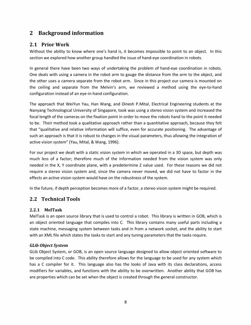
For our project we dealt with a static vision system in which we operated in a 3D space, but depth was
much less of a factor; therefore much of the information needed from the vision system was only
needed in the X, Y coordinate plane, with a predetermine Z value used. For these reasons we did not
require a stereo vision system and, since the camera never moved, we did not have to factor in the
effects an active vision system would have on the robustness of the system.
In the future, if depth perception becomes more of a factor, a stereo vision system might be required.
2.2 Technical Tools
2.2.1 MelTask
MelTask is an open source library that is used to control a robot. This library is written in GOB, which is
an object oriented language that compiles into C. This library contains many useful parts including a
state machine, messaging system between tasks and in from a network socket, and the ability to start
with an XML file which states the tasks to start and any tuning parameters that the tasks require.
GLib Object System
GLib Object System, or GOB, is an open source language designed to allow object oriented software to
be compiled into C code. This ability therefore allows for the language to be used for any system which
has a C compiler for it. This language also has the looks of Java with its class declarations, access
modifiers for variables, and functions with the ability to be overwritten. Another ability that GOB has
are properties which can be set when the object is created through the general constructor.

9
Compiled to C
This feature is possibly one of the most powerful features of the language. This is because GOB can be
used to program any system in an object oriented design. When the language is installed a compiler is
all that is needed for the GOB to C conversion. Then the compiler for C to the assembly language of the
system that is being programmed is run on the c and h files written from the GOB to C compiler. This
also allows for C code to be embedded into the GOB code therefore allowing all the C code functionality
and object oriented functionality to be written.
Properties
This feature allows for public variables that have getter and setter methods like in Microsoft’s C#
language. These properties are also how the object is created instead of using a constructor, but an init
function is also called when the object is created for any custom initialization. This ability of GOB will
also come back as an integral part of how MelTask runs and is implemented. By having automatic basic
getter and setter methods that just get or set the variable unless otherwise specified the programmer
can be lazy or add a custom getter or setter method for controlling the values of the variables.
Access Modifiers
GOB also has the access modifiers public and private. These two are easy to implement by generating
two header files, a public and a private header when there are private variables in an object. Then when
another object, object B, wants to use the first object, object A, object B only has to include the header
file generated about object A to use anything public in object A. If object B inherits from object A and
wants to use the private variables or functions in object A it only has to include the private header file as
well.
2.2.2 OpenCV
OpenCV is a widely used open source vision library originally created by Intel that provides functionality
for vision related tasks (Bradski & Kaehler, 2008). The majority of tasks are related to images and
performing transformations on images and thus OpenCV provides functionality for loading images from
files as well as capturing frames from video sources. The possible video sources that OpenCV can
capture frames from include both cameras and locally stored Audio Video Interleave (AVI) files. Once
the frame is loaded, OpenCV provides methods for performing operations on images such as converting
images to different color spaces, detecting objects within an image as well as many other operations.
OpenCV also provides functionality for creating and displaying information through Graphical User
Interfaces (GUIs). Features that are supported by OpenCV include creating windows, displaying images
within windows and adding trackbars with sliders into preexisting windows. The OpenCV library is a
great choice for performing vision related tasks due to its open source nature as well as the fact that it
makes most operations very simple to perform. The OpenCV library can be located and downloaded by
visiting the following link:
http://sourceforge.net/projects/opencvlibrary/
Creating Buttons
OpenCV does not explicitly offer a method for adding buttons to an interface; however, for this project
we deemed it a necessary function to have. In order to provide this functionality the OpenCV library was
10
edited from its original state to include a method cvCreateButton which creates a button onto a pre-
existing window. This button can be given a name, a caption, and a callback method. The callback
method will be called when the button is pressed by the user. This allows a button to be assigned a
specific function and is quite a useful feature to have enabled.
Blob Detection
Blob detection is a process through which objects in a frame are detected by analyzing groups of closely
related pixels. These pixel groups are termed blobs. Blobs are typically detected through looking for
differences in color or brightness in the areas surrounding the blob. Performing blob detection on a
frame results in a series of blobs each which have a corresponding position and size.
Open source Library cvBlobFinder
The open source library cvBlobFinder provides the functionality to easily detect all blobs within a given
frame using configurable threshold parameters. Once all the blobs have been detected, this library also
provides methods for retrieving the sequence of all blobs detected as well as the ability to retrieve any
given blob. This makes traversing the entire set of detected blobs trivial. The standard functionality of
this library was extended to support OpenCV’s image Regions of Interest which allow blob detection to
occur only on a defined rectangle subsection of the overall image. This provides the ability to greatly
reduce the blob detection area which can greatly reduce the speed of the overall detection. The
cvBlobFinder library can be downloaded by visiting the following link:
http://www.matteolucarelli.net/libreria/index.htm
Camshift
Camshift stands for “continuously adaptive meanshift” and is a technique for tracking objects within
images. The camshift technique enables you to discover features such as size, angle, and position of
masses within an image. It performs this function first by attempting to determine the center of mass
for the given image and then centering the window on the center of mass. This repeats until the window
no longer needs to change positions in order to be centered. OpenCV provides the cvCamShift function
which performs the camshift technique on a given frame (Bradski & Kaehler, 2008, pp. 337-341).
11
3 Design
3.1 Environment
The environment for this project consists of three elements: the robot, the table, and the human
participant. In order to perform certain aspects of the vision related tasks, we needed to control
particular aspects of the environment. The environment is discussed below with each of the
modifications made to control the variation.
3.1.1 Melvin
Melvin is the humanoid robot used throughout the duration of this project. Melvin was designed as a
collaboration between Mitsubishi Electric Research Laboratories (Cambridge, MA) and the University of
Sherbrooke (Quebec, Canada), and manufactured by Robomotio Inc. (Quebec, Canada). It was
purchased by WPI in 2007. Melvin has two arms and is attached to a moveable, and rotatable, base unit;
however, for this project we were only able to design, but not complete implementation of functionality
involving the base. Melvin has a total of sixteen servomechanisms which control every part of his body.
Melvin has the ability to move his arms at the shoulder as well as at the elbow. Melvin has a fully
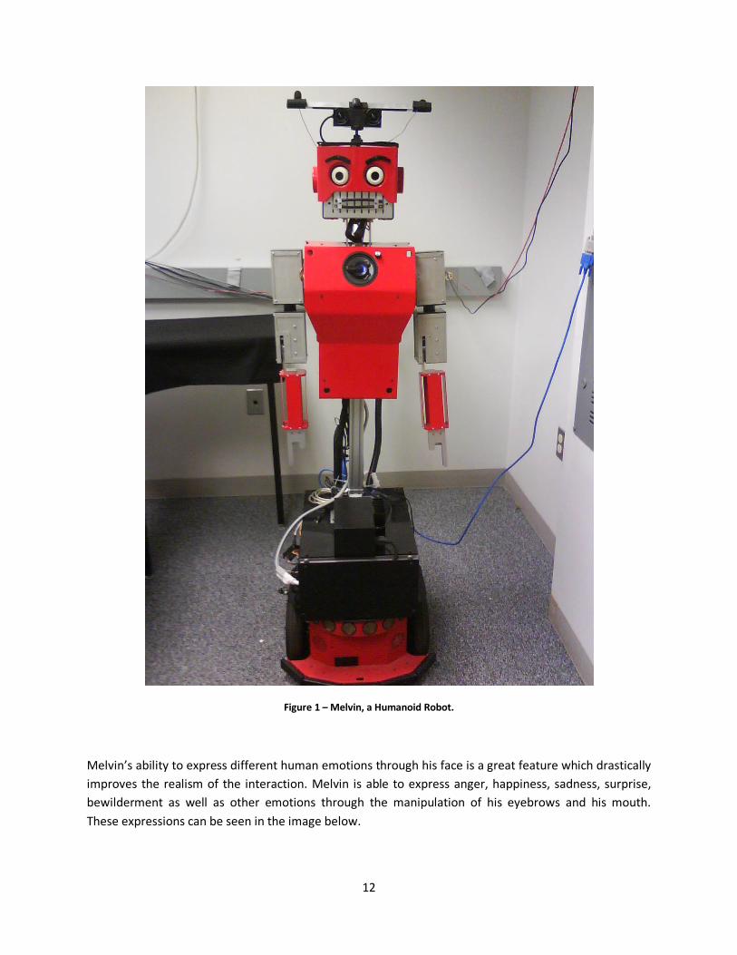
moveable face which can be used to create a series of expressions. A picture of Melvin’s full body can be
seen below.
12
Figure 1 – Melvin, a Humanoid Robot.
Melvin’s ability to express different human emotions through his face is a great feature which drastically
improves the realism of the interaction. Melvin is able to express anger, happiness, sadness, surprise,
bewilderment as well as other emotions through the manipulation of his eyebrows and his mouth.
These expressions can be seen in the image below.

13
Figure 2 – Melvin’s Fully Functional Face
While Melvin has the ability to move many parts of his body he does not have the ability to move his
fingers. Melvin is unable to move his hands in any way. His hands are in a permanent pointing state with
his index finger extended. This does not present a problem for our project due to the fact that Melvin
will only be pointing at objects rather than interacting or moving them with his hands. The lack of
mobility in the hands actually decreases the difficulty of the problem of moving Melvin’s arms to a
specific location due to the fact that there are fewer joints to properly configure.
Center of Head
In order to make detecting the center of Melvin’s head possible the addition of a square sheet of felt
was placed on top of the entirety of Melvin’s head. In the center of this felt sheet we placed a smaller
square piece of tape. The felt sheet was necessary in order to eliminate the effect of glare on top of
Melvin’s head. The small piece of tape was necessary to enable the vision system to locate the center of
Melvin’s head in any given frame. Pictured below is the top of Melvin’s head with the felt and the piece
of tape visible:
Figure 3 – Alterations to the top of Melvin’s Head.
14
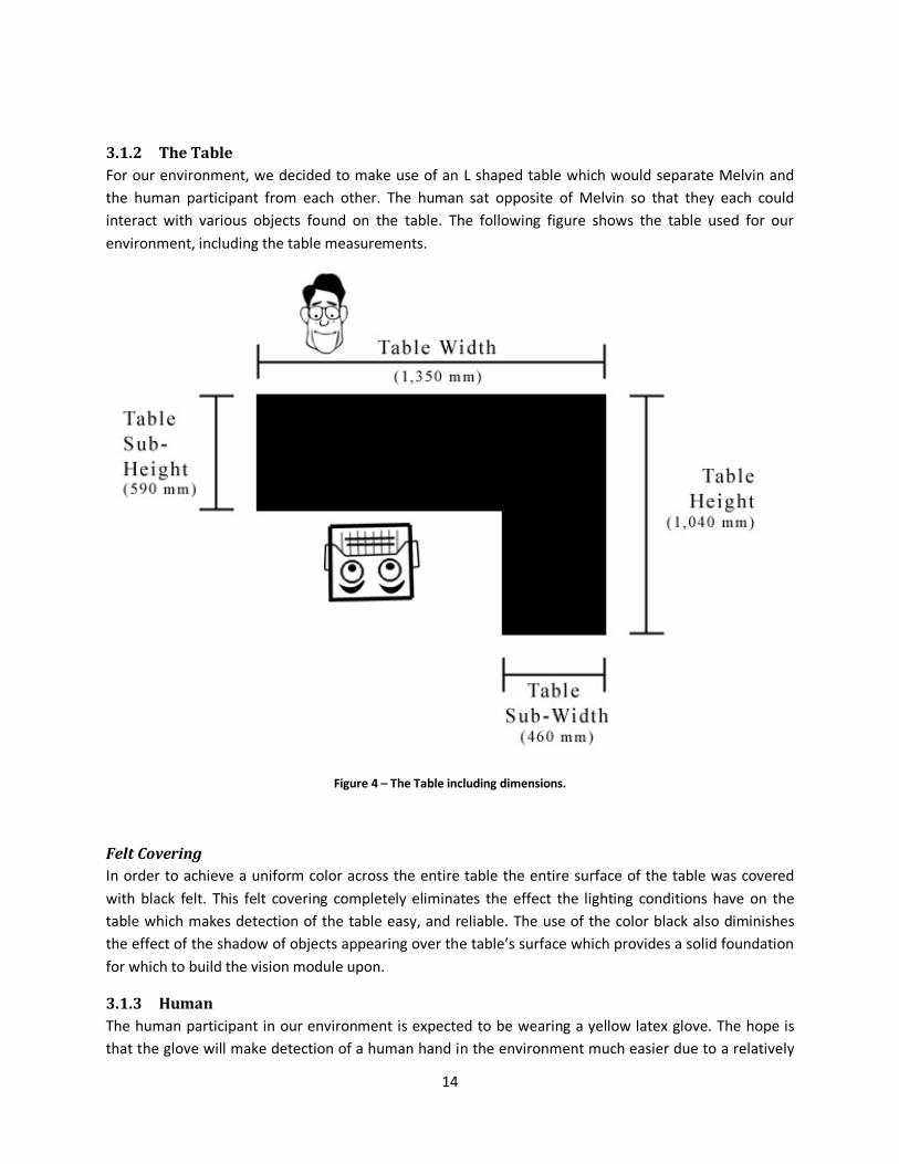
3.1.2 The Table
For our environment, we decided to make use of an L shaped table which would separate Melvin and
the human participant from each other. The human sat opposite of Melvin so that they each could
interact with various objects found on the table. The following figure shows the table used for our
environment, including the table measurements.
Figure 4 – The Table including dimensions.
Felt Covering
In order to achieve a uniform color across the entire table the entire surface of the table was covered
with black felt. This felt covering completely eliminates the effect the lighting conditions have on the
table which makes detection of the table easy, and reliable. The use of the color black also diminishes
the effect of the shadow of objects appearing over the table’s surface which provides a solid foundation
for which to build the vision module upon.
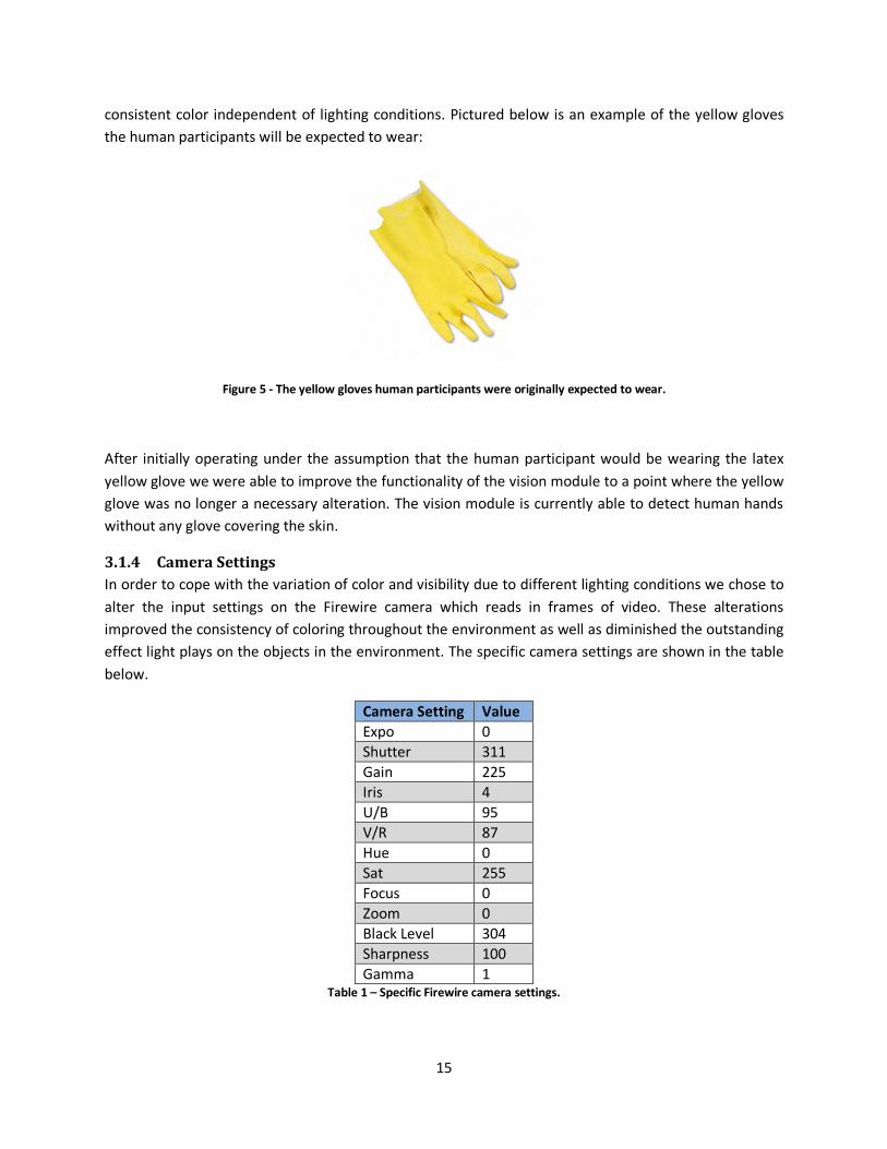
3.1.3 Human
The human participant in our environment is expected to be wearing a yellow latex glove. The hope is
that the glove will make detection of a human hand in the environment much easier due to a relatively
15
consistent color independent of lighting conditions. Pictured below is an example of the yellow gloves
the human participants will be expected to wear:
Figure 5 - The yellow gloves human participants were originally expected to wear.
After initially operating under the assumption that the human participant would be wearing the latex
yellow glove we were able to improve the functionality of the vision module to a point where the yellow
glove was no longer a necessary alteration. The vision module is currently able to detect human hands
without any glove covering the skin.
3.1.4 Camera Settings
In order to cope with the variation of color and visibility due to different lighting conditions we chose to
alter the input settings on the Firewire camera which reads in frames of video. These alterations
improved the consistency of coloring throughout the environment as well as diminished the outstanding
effect light plays on the objects in the environment. The specific camera settings are shown in the table
below.
Camera Setting Value
Expo 0
Shutter 311
Gain 225
Iris 4
U/B 95
V/R 87
Hue 0
Sat 255
Focus 0
Zoom 0
Black Level 304
Sharpness 100
Gamma 1 Table 1 – Specific Firewire camera settings.

16
Many of the settings shown above were left unchanged; however, several were altered in order to
improve the image the camera was producing. The settings we changed were: Shutter, Gain, Saturation,
and Sharpness.
3.1.5 Lighting Conditions
The ability of the vision module to perform object detection is dependent upon the specific lighting
conditions of the environment. With the lights at full brightness the effect of glare begins to alter the
appearance of objects in the environment. For our environment, we found that having the lights at a
dimmer setting yielded the most consistent results in regards to object detection. However, once we
implemented the changes to the camera settings discussed above we were able to use the lights at full
brightness.
3.2 Architecture
The Architecture consists of four modules: the vision module, the supervisor module, the control
module, and the diagnostic module. These four modules each have their own separate function;
however, it is through the interactions between the modules that the overall system meets its goals. The
following diagram shows the architecture of the system and how the modules interact.
Figure 6 – Overall Architecture Diagram

17
There are two machines involved in the functionality of the system: Vile and Valorous. Vile, which runs
Windows XP, is host to the vision, supervisor, and the diagnostic modules. Valorous, which runs Ubuntu,
is host to the control module. The vision module receives frames of video feed from a camera connected
through a Firewire port, which it processes to locate objects. Once detected, the vision module relays
these objects to the supervisor module through a socket connection between the two modules. The
supervisor uses these objects in order to control the turn taking of the interaction. The supervisor sends
commands through a socket connection to the control module which will then be sent to the robot
through a Serial port connection. These individual commands are received on a Printed Circuit Board
(PCB) chip and then relayed through Pulse-width Modulation (PWM) connection to the individual
servomechanisms of the robot. In order to control the robot’s ability to speak the speech is first
synthesized in the control module and then sent through a speaker cable to the robot’s speaker where it
is then played through the speaker. The diagnostic module provides a graphical interface for use by a
human debugger which allows the human to control the angles of the robot’s joints by sending
messages to the control module through a socket connection. The diagnostic module is intended for
debugging purposes and thus it functions separately from the rest of the system.
3.3 Control Module
This program in the project will receive a command from the supervisor and figure out what the angles
of each joint in an arm should be to point at the given location from the supervisor. This is done by
using a pre-existing framework that is now open-source from Mitsubishi Electric called MelTask. There
are a couple of ways to control the arm, either by inverse kinematics or by a closed control loop for fine
control. For this MQP we focused on the inverse kinematic approach to controlling the arm.
3.3.1 Incoming Information
When the supervisor, described below, wants Melvin to either point to a location in 3d space or to look
at a point in 3d space, a command is sent with the location of Melvin and the location of the point. In
order to find the relative point that Melvin should point or look to, the x and y location of the center of
Melvin’s head is required along with the angle of rotation of the base. This allows for the frame of
reference to be anywhere. The point is then given as another location, and the offset is calculated in the
control program. All z values, the height, are given relative to the ground.
3.3.2 Positioning Formulas
A series of mathematical formulas were required in order to find the exact point to either look at or
point to. The first item that is needed for both pointing and looking is to find the point relative to the
center of the base of the robot. This is so that there is a common frame of reference in the control
code. Next are the series of formulas used to calculate the relative point.
������ = ��� ��� − ℎ� � �����
��� ��� � = ������ � ∗ cos������ ���� + ������ � ∗ sin ������ ����
��� ��� � = ������ � ∗ sin������ ���� + ������ � ∗ cos ������ ����
��� ��� � = ��� ��� �

18
Pointing
For the pointing command there are a couple more concerns besides the offset. The first of which is
that Melvin cannot reach certain areas around him. The image below shows these regions. When
Melvin has the ability to reach the point without turning the base, he will use just the arm joints to reach
the point. If Melvin cannot reach the point, the base will turn the required amount in order to reach the
point. In this way the amount that the base turns, which takes more time to move than an arm joint, is
minimized. Below the image are the formulas used to calculate the required position of the joints.
Figure 7 - Melvin's Reachable Areas
� ��� �� = !��ℎ�"���� � − ��� ��� ��# + ��ℎ�"���� � − ��� ��� ��# + ��ℎ�"���� � − ��� ��� ��#
��$�% ��� = acos � � ��� ��# − ���� � ����ℎ# − "���� � ����ℎ#−2 ∗ "���� � ����ℎ ∗ ���� � ����ℎ �
�ℎ�"���� ���ℎ = acos (�ℎ�"���� � − ��� ��� � � ��� �� ) − asin �sin���$�% ���� ∗ ���� � ����ℎ
� ��� �� �
�ℎ�"���� � % �� $ �� ��� = ±asin ��ℎ�"���� � − ��� ��� � � ��� �� �
Looking
For looking at a location in 3d space the problem becomes somewhat simpler since there are only two
axes to worry about. However once the two angles to the object are found, the eyes and the head must
turn in a human like way. This requires an algorithm to determine how far to turn the head versus the
eyes. So long as the point is in front of Melvin, has a positive y value, the point is able to be viewed.
Melvin does not turn to look at an object because he may be engaged in pointing at the same object or a
different object. Below are the algorithms that are used to find the eye and head movement, given that
the relative angles are again calculated the same.
19
� ��� �� = ��� � − ��� ��� �
� ��� �� = ��� � − ��� ��� �
��� � � % = atan (� ��� ��� ��� ��)
��� � ���ℎ = atan , ��� � − ��� ��� �!� ��� ��# + � ��� ��#-
��� ���ℎ = ��� � ���ℎ − � �� ��. ���ℎ
��� � % = ��� � � % − � �� ��. � %
ℎ� � ���ℎ = 0.05 ∗ ��� � ���ℎ + 0.95 ∗ � �� ��. ���ℎ
ℎ� � � % = 0.05 ∗ ��� � � % + 0.95 ∗ � �� ��. � %
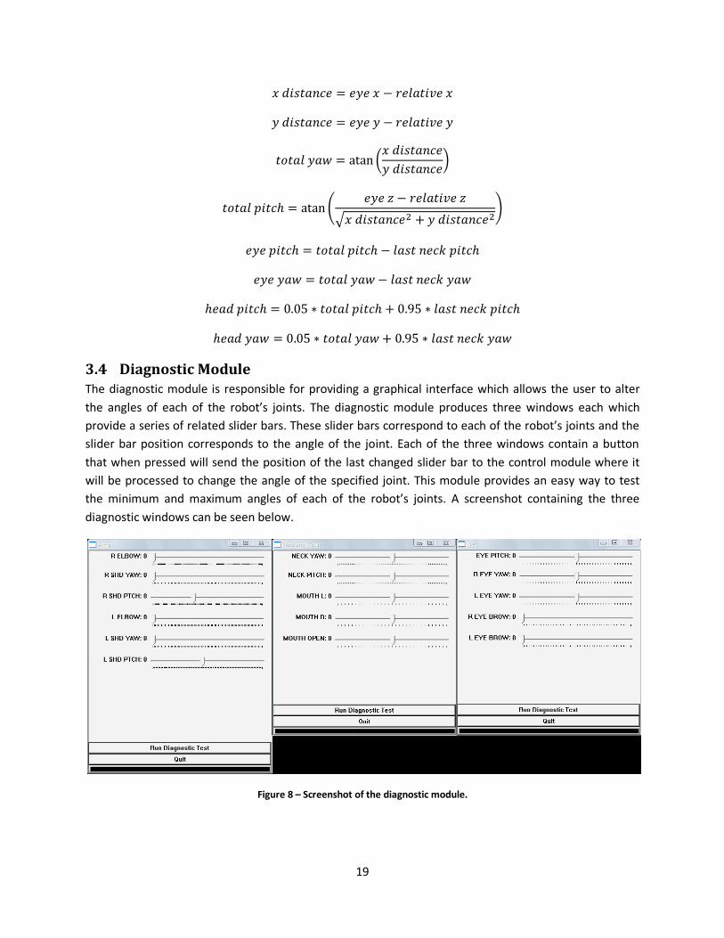
3.4 Diagnostic Module
The diagnostic module is responsible for providing a graphical interface which allows the user to alter
the angles of each of the robot’s joints. The diagnostic module produces three windows each which
provide a series of related slider bars. These slider bars correspond to each of the robot’s joints and the
slider bar position corresponds to the angle of the joint. Each of the three windows contain a button
that when pressed will send the position of the last changed slider bar to the control module where it
will be processed to change the angle of the specified joint. This module provides an easy way to test
the minimum and maximum angles of each of the robot’s joints. A screenshot containing the three
diagnostic windows can be seen below.
Figure 8 – Screenshot of the diagnostic module.
20
3.5 Supervisor Module
The supervisor module is responsible for accepting the data collected by the vision module and parsing
it further prior to relaying specific tasks to the control module. Using the objects discovered by the
vision module the supervisor determines which objects are being indicated by the human and also is
responsible for establishing the turn taking of the overall interaction. During the control of the turns the
supervisor relays specific turn related tasks to the control module where they will be executed in order
to be sent to the robot. These tasks include: pointing to a location, looking at a location, and
synthesizing a string of text into speech. The supervisor relays these tasks to the control through the use
of a socket connection established between the supervisor and control modules.
3.5.1 Incoming Information
The supervisor receives information in the form of string messages which are sent via a socket
connection between the vision and the supervisor modules. The supervisor parses each of the received
messages into a series of objects which are used to determine the transitions between states. The
objects received from the vision system correspond to the existing objects within the environment.
These objects are also used when relaying tasks to the control module.
3.5.2 Indicated Objects
Once the supervisor has parsed the incoming messages for the series of objects detected it begins to
analyze the objects in order to determine which of the objects, if any, are being pointed to by the
human. The supervisor uses the given information pertaining to the human hand as well as all the
objects that are currently on the table in order to establish which objects are being indicated by the
human hand.
3.5.3 Turn Taking
The supervisor is responsible for controlling the overall turn taking of the interaction. The interaction
begins with the human’s turn where a human points at an object on the table. The supervisor keeps
track of which object was indicated and then transitions into the robot’s turn. The robot then extends
his arm and points at the same object. Once the robot has pointed for a certain duration his arm is sent
back to its home position and it is once again the human’s turn.
3.5.4 Outgoing Information
Once the supervisor parses the incoming messages for a series of objects that were detected within the
frames it uses these objects to determine which state to transition to in order to control the turn taking
of the interaction. Depending on the currently active state, as well as the series of detected objects, the
supervisor then relays the necessary information to the control module in order to have an action
performed by the robot.
3.6 Vision Module
The vision module is responsible for accepting input from a Firewire camera and parsing each frame of
video feed for information. In order to grab the video feed from the camera and also for parsing each
frame of feed, the vision module makes use of the OpenCV library discussed in the Technical Tools
section of this document. Using this library the vision module is able to locate objects of interest within
21
each of the frames that it analyzes. The vision system has three main tasks: self calibration, locating
objects of interest and relaying the detected objects to the supervisor. Self Calibration is performed
through locating and measuring the environment table once it is detected in the frame. Objects of
interest include: plates, hands, the robot’s head as well as the environment table. Once detected the
vision system then delivers all the detected objects to the supervisor where they will be analyzed prior
to being sent to the control system. The information is relayed through a socket connection established
between the vision and the supervisor modules.
All the figures pictured below are screen shots taken directly from the output of the vision module.
3.6.1 Self Calibration
The vision module is responsible for analyzing frames of video feed in order to calibrate itself to the
environment. It achieves this goal by locating the table within the frame and then determining the
number of pixels that correspond to a single millimeter through knowledge of the exact millimeter table
measurements. Once the conversion factor is determined a coordinate system can be established in
order to convert pixel coordinates into real world coordinates prior to relaying the information to the
supervisor. This process allows the vision module to calibrate itself to the environment which makes it
more adaptable to change within the environment.
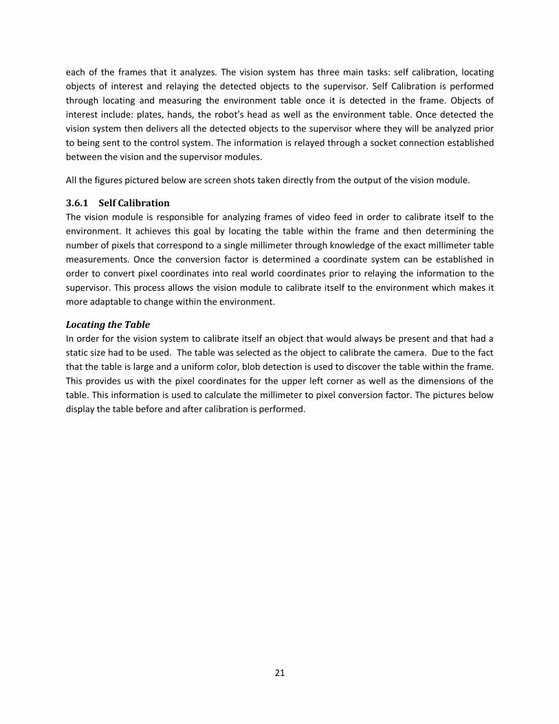
Locating the Table
In order for the vision system to calibrate itself an object that would always be present and that had a
static size had to be used. The table was selected as the object to calibrate the camera. Due to the fact
that the table is large and a uniform color, blob detection is used to discover the table within the frame.
This provides us with the pixel coordinates for the upper left corner as well as the dimensions of the
table. This information is used to calculate the millimeter to pixel conversion factor. The pictures below
display the table before and after calibration is performed.
22
Example of Table Detection
Figure 9 – Detection of the Table.
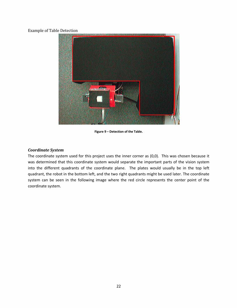
Coordinate System
The coordinate system used for this project uses the inner corner as (0,0). This was chosen because it
was determined that this coordinate system would separate the important parts of the vision system
into the different quadrants of the coordinate plane. The plates would usually be in the top left
quadrant, the robot in the bottom left, and the two right quadrants might be used later. The coordinate
system can be seen in the following image where the red circle represents the center point of the
coordinate system.
23
Figure 10 – Coordinate System
3.6.2 Object Detection
There are several objects of interest that this vision system is responsible for recognizing in each frame.
These objects include: plates, human hands, robot hands, and the robot’s orientation. The process of
identifying each of these objects is described below.
Blob Detection
The first step in detecting objects is to perform blob detection on the current frame using the open
source blob detection library discussed in the Technical Tools section of this document. However, rather
than performing this on the entire frame, a region of interest corresponding to the table is used to
narrow down the search area. This region of interest can be assumed because we are only interested in
detecting plates and hands when they appear over the table. The result of the blob detection operation
is a sequence of blobs that fall within the boundary of the table where a blob has a position in the frame
as well as an area.
Hand Detection
Using the sequence of blobs described above we now analyze each of the detected blobs for hands.
Hands, both human and robot, appear as the same color in each frame, therefore, each of the blobs in
the sequence is matched against the expected color to determine which blobs are possible hands and
which blobs are not. All blobs that match the expected color are then sorted into robot hands or human
hands depending on certain characteristics described below.
24
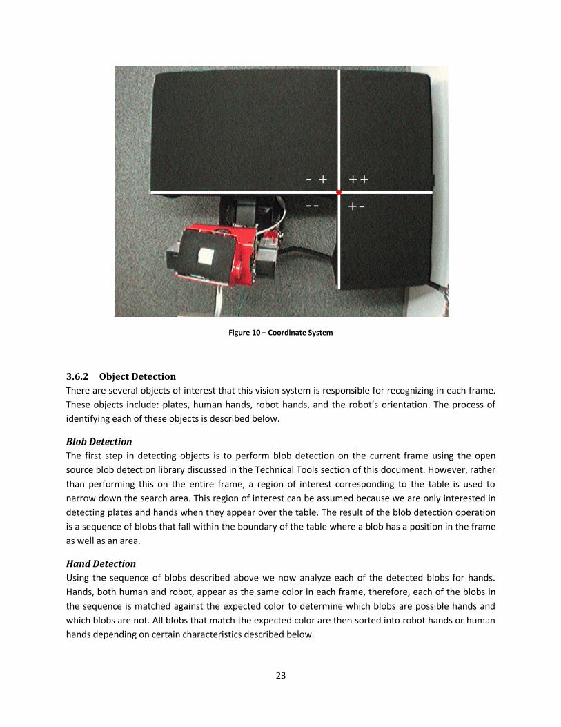
Robot Hand
Robot hands are determined by area as well as position in the frame. A robot hand is much smaller than
a human hand and is in a fixed position while a human hand has the ability to change sizes. A robot hand
will always enter the frame at the bottom while a human hand will always enter the frame from the top
due to the positions of both the human and the robot. These two characteristics allow us to distinguish
which blobs are robot hands. Camshifting is then performed on the blob in order to determine the
blob’s angle as well as for continued detection of the hand once it is originally found. This works
particularly well for robot hands due to the fact that, once detected, the robot hand will never exit the
frame. The figure below shows the environment before and after the detection of the robot hand is
performed.
Example of Hand Detection
Figure 11 – Detection of the Robot Hand.
Human Hand
Due to the fact that human hands take on various shapes and sizes any possible hand that is not thought
to be a robot hand is assumed to be a human hand. This allows the greatest chance of detecting the
hand in any state. Camshifting is then performed on the blob in order to determine the blob’s angle as
well as to continue to track the hand as it moves around the table. The figure below shows the
environment before and after human hand detection is performed.
25
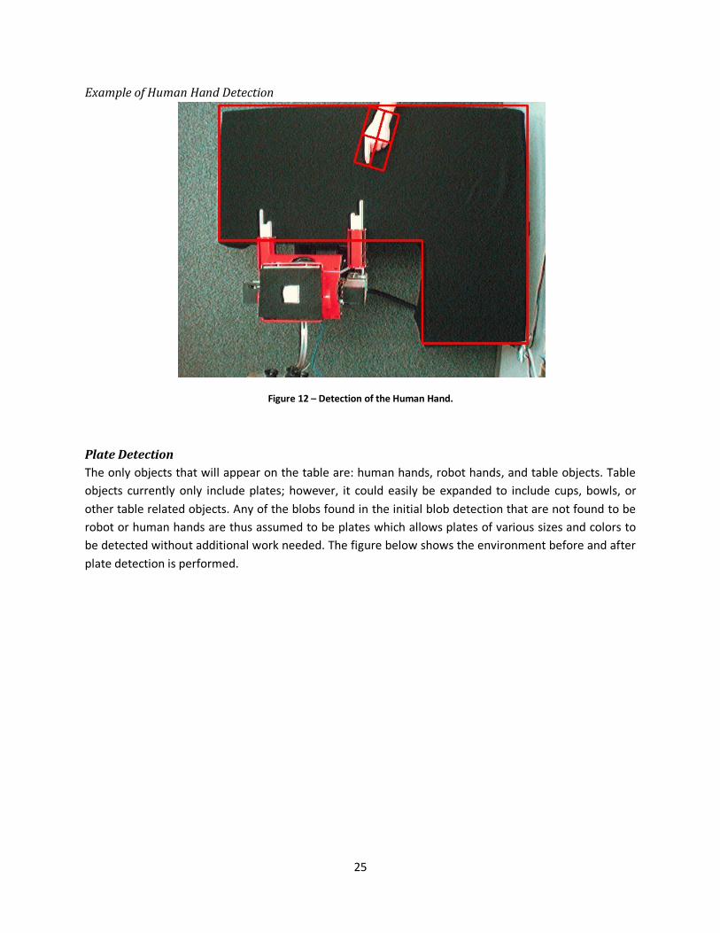
Example of Human Hand Detection
Figure 12 – Detection of the Human Hand.
Plate Detection
The only objects that will appear on the table are: human hands, robot hands, and table objects. Table
objects currently only include plates; however, it could easily be expanded to include cups, bowls, or
other table related objects. Any of the blobs found in the initial blob detection that are not found to be
robot or human hands are thus assumed to be plates which allows plates of various sizes and colors to
be detected without additional work needed. The figure below shows the environment before and after
plate detection is performed.

26
Example of Plate Detection
Figure 13 – Detection of Several Different Colored Plates.
Robot Detection
There are two important aspects of the robot that need to be detected in order to establish the robot’s
position in respect to the table. The first characteristic is the center of the robot’s head and the second
is the orientation of the robot. The processes for detecting these two aspects are described below.
Position
In order to detect the center of the Robot’s head we placed a square piece of tape on the top of his
head which corresponds to the center of his head. Below the tape we placed a black piece of felt that
spans the entirety of the top of his head. The felt keeps the light conditions from altering the detection
by diminishing the glare on the top of the head. With these two items in place we can use blob
detection on a region corresponding to where the robot will appear to locate the center of his head. The
figure below shows the environment before and after robot head detection is performed.
27
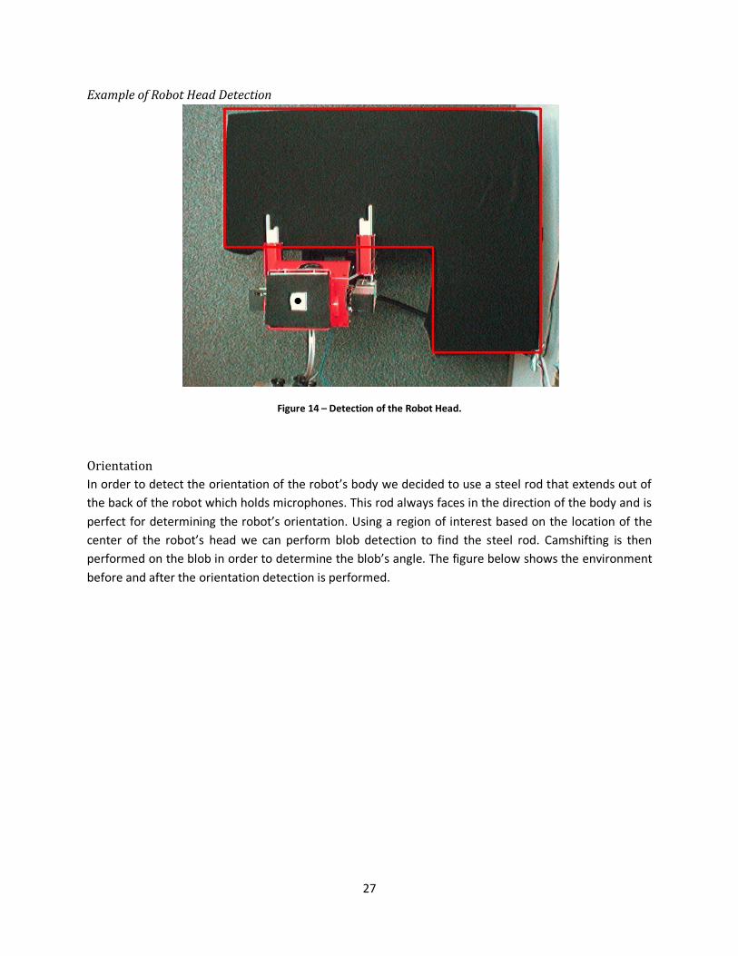
Example of Robot Head Detection
Figure 14 – Detection of the Robot Head.
Orientation
In order to detect the orientation of the robot’s body we decided to use a steel rod that extends out of
the back of the robot which holds microphones. This rod always faces in the direction of the body and is
perfect for determining the robot’s orientation. Using a region of interest based on the location of the
center of the robot’s head we can perform blob detection to find the steel rod. Camshifting is then
performed on the blob in order to determine the blob’s angle. The figure below shows the environment
before and after the orientation detection is performed.
28
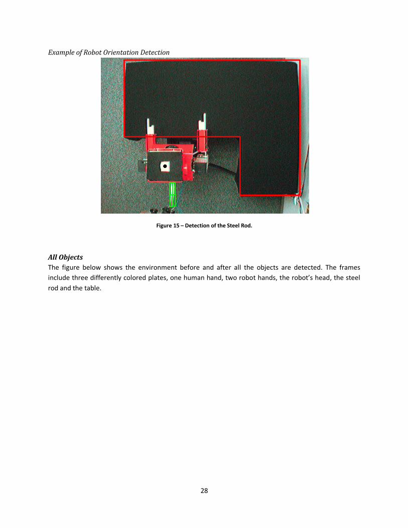
Example of Robot Orientation Detection
Figure 15 – Detection of the Steel Rod.
All Objects
The figure below shows the environment before and after all the objects are detected. The frames
include three differently colored plates, one human hand, two robot hands, the robot’s head, the steel
rod and the table.
29
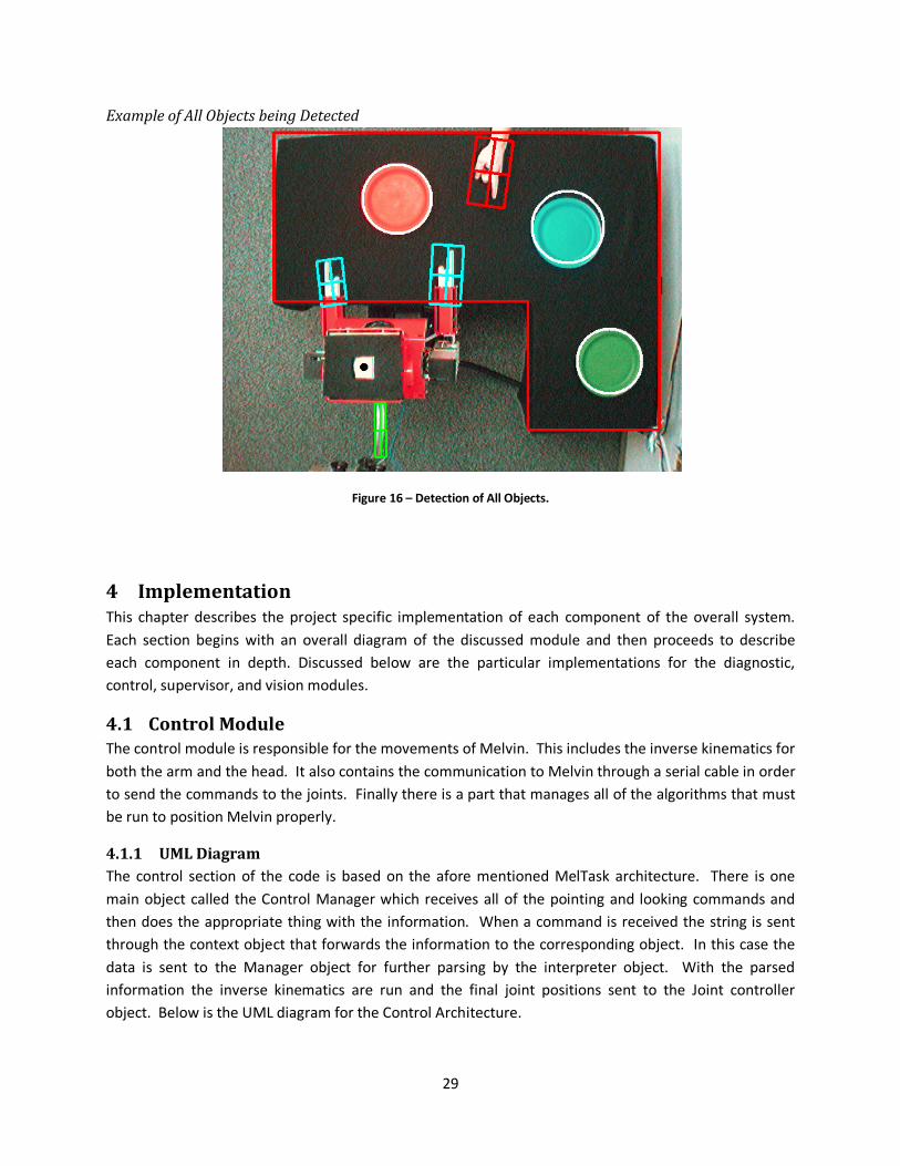
Example of All Objects being Detected
Figure 16 – Detection of All Objects.
4 Implementation This chapter describes the project specific implementation of each component of the overall system.
Each section begins with an overall diagram of the discussed module and then proceeds to describe
each component in depth. Discussed below are the particular implementations for the diagnostic,
control, supervisor, and vision modules.
4.1 Control Module
The control module is responsible for the movements of Melvin. This includes the inverse kinematics for
both the arm and the head. It also contains the communication to Melvin through a serial cable in order
to send the commands to the joints. Finally there is a part that manages all of the algorithms that must
be run to position Melvin properly.
4.1.1 UML Diagram
The control section of the code is based on the afore mentioned MelTask architecture. There is one
main object called the Control Manager which receives all of the pointing and looking commands and
then does the appropriate thing with the information. When a command is received the string is sent
through the context object that forwards the information to the corresponding object. In this case the
data is sent to the Manager object for further parsing by the interpreter object. With the parsed
information the inverse kinematics are run and the final joint positions sent to the Joint controller
object. Below is the UML diagram for the Control Architecture.
30
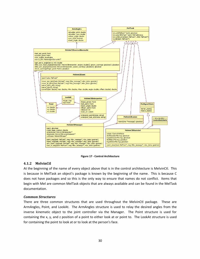
Figure 17 - Control Architecture
4.1.2 MelvinCtl
At the beginning of the name of every object above that is in the control architecture is MelvinCtl. This
is because in MelTask an object’s package is known by the beginning of the name. This is because C
does not have packages and so this is the only way to ensure that names do not conflict. Items that
begin with Mel are common MelTask objects that are always available and can be found in the MelTask
documentation.
Common Structures
There are three common structures that are used throughout the MelvinCtl package. These are
ArmAngles, Point, and LookAt. The ArmAngles structure is used to relay the desired angles from the
inverse kinematic object to the joint controller via the Manager. The Point structure is used for
containing the x, y, and z position of a point to either look at or point to. The LookAt structure is used
for containing the point to look at or to look at the person’s face.
31
Inverse Kinematics
This object takes the point that the robot should point to and the current position of the robot’s head
and the direction that it is pointing. The angles are then calculated by selecting which arm to use based
on the sideways displacement (x). The first joint to be found is the elbow since this can be found by the
distance from the shoulder. Then the shoulder joints and base rotation are found based on the xyz
positions. The formulas in the section above named Positioning Formulas are used to calculate the joint
angles for either the arm or the head and eyes.
Interpreter
This object has many functions for each kind of message that can come across. When the manager
object receives a message it sends the string over to the interpreter object through the corresponding
function to parse it. These values are then stored in the interpreter object which gets passed to the
inverse kinematic object for each of the values that are needed. This is done by reading each of the
numbers in the string in the predetermined order and storing them to the corresponding attribute.
Joint
This object is what actually moves each of the joints to the specified positions. This movement is done
by sending a message to this object through the message box system built into MelTask. Upon receipt
of the message, child objects are made to position each joint. There are two different types of
messages. First is the single joint at a time and then a message for all of the joints at a time. These
messages allow the diagnostic panel to move each joint via the network as well.
State Init
This object is used to initialize the system and the joints such that Melvin does not attempt to go
through the table. This happens by first bringing the arms back and around the table. Then the elbows
are bent to 90° so that they are above the table. Followed by the arms are returned to Melvin’s side so
that the upper arm portion is pointing straight down and the forearm part is parallel to the table,
pointing toward the opposite side of the table.
Comm
This object is used to send commands from the running MelTask program to the base of Melvin which is
running another MelTask program to control the rotation of the base. This communication is done
through a simple socket like the communication from the vision system to the control system. There are
two important commands for turning the base which are absolute and relative.
Manager
This object receives all of the commands that come in from the socket via the context. When a point
command is issued, the data is sent through the interpreter and then to the inverse kinematics. When a
look at command is issued the interpreter pulls out the data and then again through a different inverse
kinematic function in order to calculate the values for the two neck joints. There are also two home
commands that can be issued which will automatically move the joints to the home positions. These
commands are talked about in the following supervisor section.
32
4.2 Diagnostic Module
The diagnostic module is responsible for providing a graphical interface through which a human
debugger can manually adjust any of the robot’s joints. Each joint is represented in the interface by a
slider bar which can then be adjusted to the desired angle for any particular joint. The updated joint
angle can then be sent through a socket connection to the control module where the message will be
relayed to the robot. Described below is the overall architecture of the diagnostic module as well as
descriptions for each individual component.
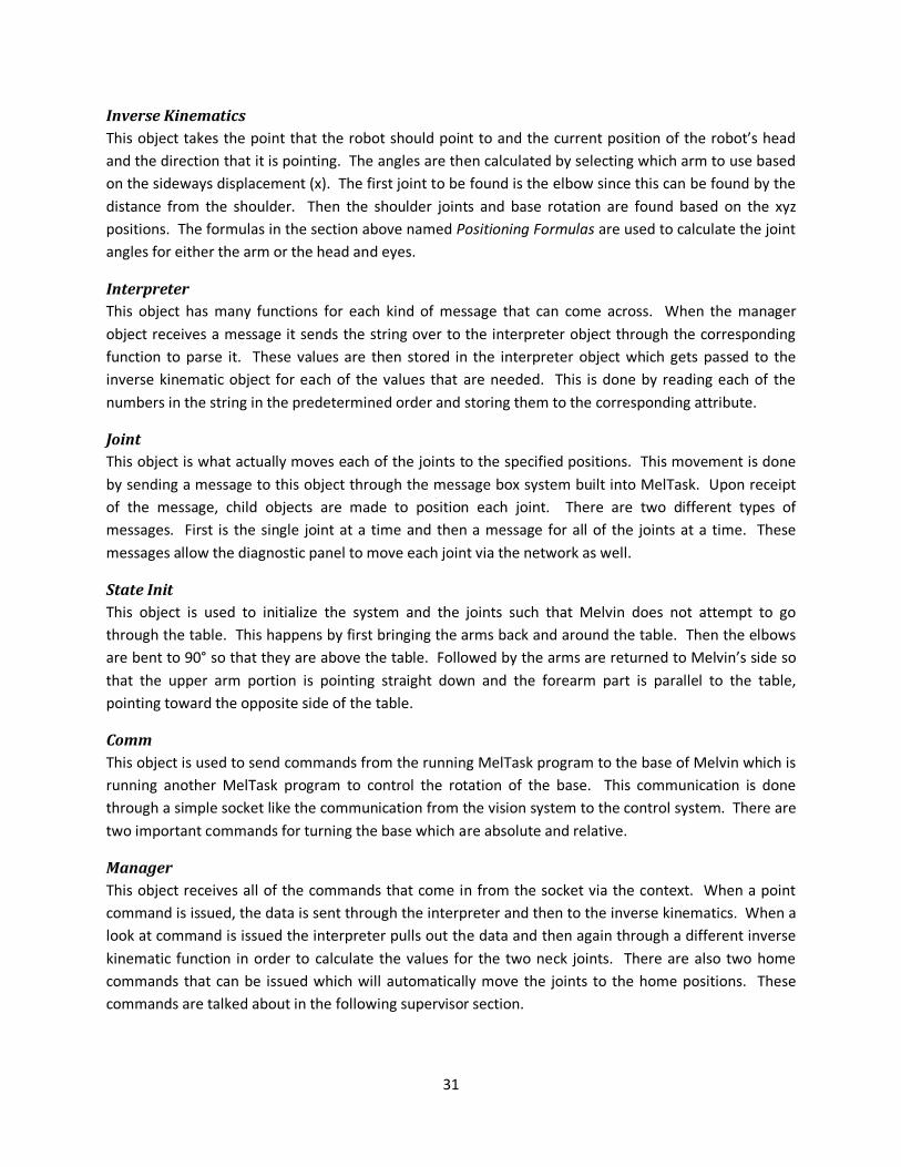
4.2.1 UML Diagram
The diagnostic module provides the ability to manipulate each of the joint angles of the robot in an easy
manner. The diagnostic module provides a slider bar for each joint angle. These slider bars can be
moved back and forth and then they can be relayed to the control module in order to move the robot’s
joints to the angles specified by the slider bars. Each slider bar has a minimum and a maximum value
associated with it which correlates to the minimum and maximum values of the joint angle. The UML
diagram for the diagnostic module is depicted in the image below.
Figure 18 – Diagnostic module UML Diagram

33
4.2.2 melDiagnosticConfig
The melDiagnosticConfig object is responsible for parsing command line options as well as loading a
configuration file. This object stores the specified values for any configured settings such that command
line options override any settings stored through the configuration file. The implemented settings are
described below.
Command Line Options
There are several settings that are configurable from the command line. Those options include:
hostname, server port and verbose setting. All settings that are indicated through the command line
override any settings that were applied from the loaded configuration file.
Flag Example Description
-h 127.0.0.1 The hostname setting consists of the sequence of characters following the flag,
up until the first whitespace character, is taken to be the desired hostname.
-p 22022 The port setting consists of the integer value following the flag, up until the first
whitespace character, is taken to be the desired port number.
-v When the verbose setting is configured status messages are displayed while the
program is running. These messages are not displayed when the verbose setting
is not configured. Using this flag activates the verbose setting. Table 4.1 – Diagnostic module command line options.
Configuration File
The configuration file allows certain settings to be loaded into the system through a file. The file has the
ability to contain comments, empty lines as well as settings. Settings can be configured by using a tag
which corresponds to the desired setting followed by the value for the setting. Possible settings include:
message header, hostname, port, and verbose.
Structure
The configuration file has a very basic structure. All lines that begin with a pound (#) character indicate
comments and are ignored by the configuration parser. Lines that are left blank, or do not contain any
characters other than whitespace, are also ignored by the configuration parser. Settings are configured
by using a TAG: VALUE format. The TAG indicates the setting to configure and the VALUE indicates the
value that the setting should be configured to. The TAG must be followed by a single colon which is then
followed by a single space. All TAGs are required to be in uppercase for processing while the VALUEs are
not case sensitive.
Implemented Settings
There are several settings that can be configured from the configuration file. The setting is indicated in
the configuration file in the following format: TAG: VALUE. Where TAG is the name of the setting to be
configured, which must be followed by a colon and then a single space, and VALUE is the value this
particular setting should be configured to. The possible settings are: the message header, the hostname,
the port, and the verbose setting. The following sections describe how to configure each of these
settings.

34
Settings Descriptions
HOSTNAME The hostname of the machine where the control module is located.
SERVER_PORT The port number of the machine where the control module is located.
MESSAGE_HEADER A string placed at the beginning of each message sent to the control module.
LOG_FILE The path to the file where messages should be logged.
VERBOSE TRUE, messages are logged. FALSE, messages are not logged. Table 4.2 – Diagnostic configuration settings and descriptions.
4.2.3 melDiagnosticSystem
The melDiagnosticSystem isolates the main function of creating a display from the rest of the module.
This class is responsible for facilitating the use of the other components such as the configuration class,
and the socket class. The main functions of the melDiagnosticSystem are described below.
createDisplay
This is the melDiagnosticSystem method responsible for creating the graphical interface. This function
takes a series of parameters which it uses in order to create the interface. The interface is divided into
three windows each of which contains a series of related slider bars. Each slider bar has a label which
describes its corresponding joint. At the bottom of each window are two buttons. The first button
labeled “Run Diagnostic Test” performs the action of relaying the position of only the most recently
changed slider bar to the control module. The other button labeled “Quit” exits the diagnostic program.
The createDisplay function uses OpenCV to create each of the interface components.
relayAngles
This function is responsible for performing the task of sending the positions of the slider bars to the
control module as messages. This function determines which slider bar was most recently changed and
once this change is determined, a message corresponding to the related joint is constructed. The
relayAngles function then sends this message to the control module through an open socket connection.
trackbarNotify
The trackbarNotify method is called in the event that the position of any of the interface slider bars is
changed. This method takes one parameter which is the new position of the slider bar that changed.
Using this parameter the trackbarNotify method determines which of the slider bars was updated and
stores that change in order to update the corresponding joint.
Message Structure
In order to alter the angle of a single joint, the diagnostic module relays messages to the control
module. Each message issues the command followed by the joint name and the angle at which the joint
should be moved to. The following table contains the names for each joint along with the description of
the joint.

35
Joint Name Description
ELBOW_R The right elbow.
SHOULDER_YAW_R The right shoulder yaw.
SHOULDER_PITCH_R The right shoulder pitch.
ELBOW_L The left elbow.
SHOULDER_YAW_L The left elbow yaw.
SHOULDER_PITCH_L The left elbow pitch.
NECK_YAW The yaw of the neck.
NECK_PITCH The pitch of the neck.
MOUTH_L The left mouth joints.
MOUTH_R The right mouth joints.
MOUTH_OPEN The distance the mouth is open.
EYE_PITCH The pitch of the eyes.
EYE_YAW_R The right eye yaw.
EYE_YAW_L The left eye yaw.
EYE_BROW_R The right eye brow.
EYE_BROW_L The left eye brow. Table 4.3 – Names of each joint.
The following is the command used to set the angle of a given joint:
/melvinCtl/moveOneJoint [Joint Name] [Angle in Degrees]
Therefore, in order to change the angle of the left elbow to 90 degrees the following message would be
sent:
/melvinCtl/moveOneJoint ELBOW_L 90
The message header ‘/melvinCtl/’ is required in order for the control module to understand the
incoming message and handle it properly.
4.3 Supervisor Module
The supervisor acts as a mediator between the vision system and the control system. The supervisor
receives messages from the vision system indicating the objects detected within the environment. The
supervisor then parses the detected objects and relays the information that is relevant to the control
system. The information relayed to the control system is dependent upon the desired functionality.
4.3.1 UML Diagram
The supervisor module contains several objects which work together in order to complete supervisor
related tasks. The supervisor uses states to keep track of the overall state of the interaction and also to
keep track of where the robot is currently looking. These states transition between each other
depending on what information is being received from the vision system. The supervisor module also
has a configuration object which is responsible for loading and storing settings contained in a
configuration file. A socket object also exists in order to retrieve the messages from the vision module
and also to relay information to the control module. The UML diagram for the supervisor module is
depicted in the image below.

36
Figure 19 – Supervisor module UML Diagram
4.3.2 melSupervisorConfig
The melSupervisorConfig object encapsulates the responsibilities of loading and setting configuration
settings for the supervisor. It extends the melIConfig interface and provides implementation for all the
abstract methods of the interface. The melSupervisorConfig object is given a specific configuration file to
load, which it parses for settings and then stores the settings accordingly.
Command Line Options
There are several settings that are configurable through command line arguments. Any settings
configured through the command line override any previous settings that were determined by a
configuration file. The implemented settings are: server hostname, server port, client port and verbose.

37
Flag Example Description
-h 127.0.0.1 The hostname setting indicates the hostname for the control system where the
supervisor will be sending messages. Setting this option in the command line
overrides any previously configured hostname settings.
-p 22022 The server port number corresponds to the port number for the control system
where the supervisor will be sending messages. Setting this option via the command
line overrides any previously set server port setting.
-l 55055 The client port number corresponds to the port number that the supervisor will bind
itself to and open to listen for incoming messages from the vision system. Setting this
option via the command line overrides any previously set client port setting.
-w 2000 The point wait duration setting sets the number of milliseconds that Melvin’s hand
will remain pointing at an object.
-v The verbose setting enables the verbose setting during the programs runtime. When
enabled the verbose setting allows status messages to be printed to the console
window while the program is running. When it is disabled the status messages are
not displayed. Use of this flag activates the verbose setting. Table 4.4 – Command line options for the supervisor module.
Configuration File
The configuration file allows certain settings to be loaded into the system through a file. The file has the
ability to contain comments, empty lines as well as settings. Settings can be configured by using a tag
which corresponds to the desired setting followed by the value for the setting. Possible settings include:
message header, server hostname, server port, client port and verbose.
Structure
The configuration file has a very basic structure. All lines that begin with a pound (#) character indicate
comments and are ignored by the configuration parser. Lines that are left blank, or do not contain any
characters other than whitespace, are also ignored by the configuration parser. Settings are configured
by using a TAG: VALUE format. The TAG indicates the setting to configure and the VALUE indicates the
value that the setting should be configured to. The TAG must be followed by a single colon which is then
followed by a single space. All TAGs are required to be in uppercase for processing while the VALUEs are
not case sensitive.
Implemented Settings
There are several settings that can be configured for the supervisor through the configuration file. These
settings are: the message header, the server hostname, the server port, the client port and the verbose
setting.
38
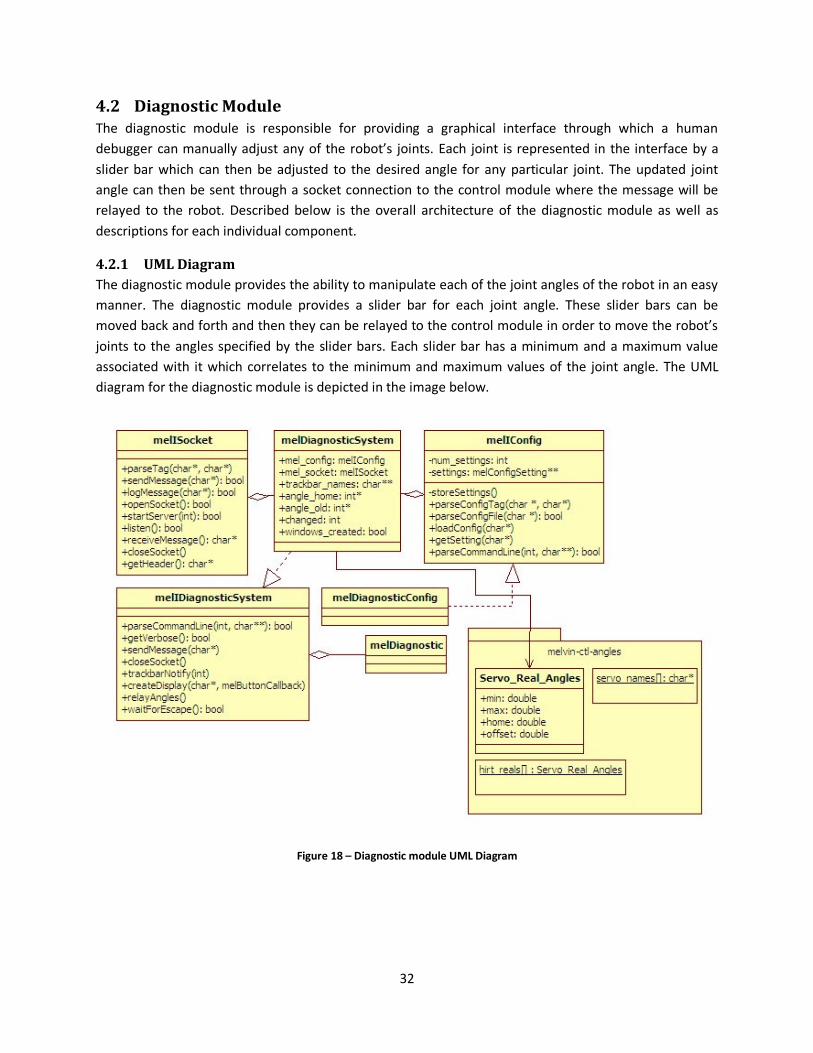
Setting Description
MESSAGE_HEADER The message header setting is configured through the MESSAGE_HEADER tag
followed by the intended message head, up until the first newline character.
Once set, the message header is placed at the beginning of every message
sent to the control system which allows the control system to correctly
identify and parse to the incoming messages.
HOSTNAME The server hostname setting is configured using the HOSTNAME flag followed
by the desired hostname, up until the first newline character. The server
hostname setting is the hostname of the control system where the supervisor
will be relaying messages to.
SERVER_PORT The server port setting is configured using the SERVER_PORT flag followed by
the integer port number, up until the first newline character. The server port
number is the port number for the control system where the supervisor will
be sending messages.
LISTEN_PORT The client port setting is configured using the LISTEN_PORT flag followed by
the integer port number, up until the first newline character. The client port is
the port number that the supervisor will bind itself to in order to listen for
incoming messages from the vision system.
LOG_FILE The log file setting is configured using the LOG_FILE flag followed by the
filename and path where the log file should be saved. This file will be used to
store certain information such as the messages that are sent from the
supervisor to the control module. Messages are saved to the log file when the
Verbose setting is activated.
WAIT_TIME The point wait duration setting is configured using the WAIT_TIME flag
followed by the integer number of milliseconds. This number corresponds to
the number of milliseconds that Melvin should remain pointing at a given
object. For example, if the point wait duration setting was set to 2000 then
Melvin will point at all objects for two seconds before removing his hand.
TABLE_HEIGHT The table height setting is configured using the TABLE_HEIGHT flag followed
by the integer number of millimeters. This number corresponds to the
number of millimeters from the top of the table to the floor. This setting is
used when relaying pointing positions to the control.
MIN_POINT_DURATION The minimum point duration setting is configured using the
MIN_POINT_DURATION flag followed by an integer number of milliseconds.
This number corresponds to the minimum number of frames an object must
be pointed at before it is considered to be indicated by the human. For
example, if the minimum point duration setting is set to ten then the human
hand must point at an object for at least ten frames before that object will be
considered to be pointed identified by the human.
MAX_VISIBLE_HAND The maximum visible hand duration setting is configured using the
MAX_VISIBLE_HAND flag followed by an integer number of milliseconds. This
number corresponds to the number of milliseconds that a human hand must
remain visible before Melvin looks back up at the human to show his
attentiveness. For example, if the maximum visible hand setting is set to
10000 then Melvin will wait until a human hand has been visible for ten
seconds before looking back up at the human.
39
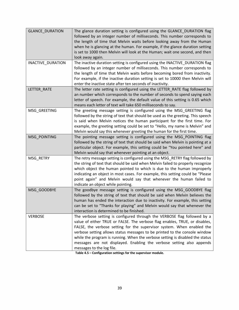
GLANCE_DURATION The glance duration setting is configured using the GLANCE_DURATION flag
followed by an integer number of milliseconds. This number corresponds to
the length of time that Melvin waits before looking away from the Human
when he is glancing at the human. For example, if the glance duration setting
is set to 1000 then Melvin will look at the Human; wait one second, and then
look away again.
INACTIVE_DURATION The inactive duration setting is configured using the INACTIVE_DURATION flag
followed by an integer number of milliseconds. This number corresponds to
the length of time that Melvin waits before becoming bored from inactivity.
For example, if the inactive duration setting is set to 10000 then Melvin will
enter the inactive state after ten seconds of inactivity.
LETTER_RATE The letter rate setting is configured using the LETTER_RATE flag followed by
an number which corresponds to the number of seconds to spend saying each
letter of speech. For example, the default value of this setting is 0.65 which
means each letter of text will take 650 milliseconds to say.
MSG_GREETING The greeting message setting is configured using the MSG_GREETING flag
followed by the string of text that should be used as the greeting. This speech
is said when Melvin notices the human participant for the first time. For
example, the greeting setting could be set to “Hello, my name is Melvin” and
Melvin would say this whenever greeting the human for the first time.
MSG_POINTING The pointing message setting is configured using the MSG_POINTING flag
followed by the string of text that should be said when Melvin is pointing at a
particular object. For example, this setting could be “You pointed here” and
Melvin would say that whenever pointing at an object.
MSG_RETRY The retry message setting is configured using the MSG_RETRY flag followed by
the string of text that should be said when Melvin failed to properly recognize
which object the human pointed to which is due to the human improperly
indicating an object in most cases. For example, this setting could be “Please
point again” and Melvin would say that whenever the human failed to
indicate an object while pointing.
MSG_GOODBYE The goodbye message setting is configured using the MSG_GOODBYE flag
followed by the string of text that should be said when Melvin believes the
human has ended the interaction due to inactivity. For example, this setting
can be set to “Thanks for playing” and Melvin would say that whenever the
interaction is determined to be finished.
VERBOSE The verbose setting is configured through the VERBOSE flag followed by a
value of either TRUE or FALSE. The verbose flag enables, TRUE, or disables,
FALSE, the verbose setting for the supervisor system. When enabled the
verbose setting allows status messages to be printed to the console window
while the program is running. When the verbose setting is disabled the status
messages are not displayed. Enabling the verbose setting also appends
messages to the log file. Table 4.5 – Configuration settings for the supervisor module.
40
4.3.3 melSupervisorSystem
The melSupervisorSystem encapsulates the functionality of the overall supervisor system. It contains the
configuration object that loads settings from a configuration file and it also contains the socket object
that controls both the sending and receiving portion of the supervisor’s responsibilities. The
melSupervisorSystem provides methods which control each aspect of the overall supervisor system
which then delegate the action to the corresponding class and object.
Message Structure
The supervisor has the ability to use many messages to achieve the desired effect on the control side.
The supervisor has the ability to tell the control module to: return the robot to the home position, look
at a specific location, synthesize speech, and point to a specific location. The following sections explain
each of the messages and how they are used.
Units of Measurement
The control module expects certain units of measurements for the information being relayed to it from
the supervisor module. Specifically in relation to object locations in space, the control module expects
the coordinates to be in centimeters while the supervisor stores all object locations in millimeters. Each
location must be converted to the expected units of measurement prior to being relayed to the control
module.
Home Position
The supervisor can tell the control module to return the entire robot to the home position, or to just
return the arms to the home position. The message to return the robot to the home position is as
follows:
/melvinCtl/home
This returns each of the robot’s joints to their home position. The message to return only the robot’s
arms to the home position is as follows:
/melvinCtl/armHome
This returns only the robot’s arms to their home position while the rest of the robot remains unmoved.
Looking at a Location
The supervisor has the ability to ask the control module to have the robot look at a specific location, or
to look at the human. When executing this command the robot moves first his eyes to look at the
intended point and only moves his head if the point is outside of the range of points visible from the
current head orientation. The exact calculations used to determine where the robot looks are described
in Section 3.3.2.
The message to have the robot look at a specific location is as follows:
/melvinCtl/lookAt point [Head center] [Rotation] [Look location] [Timeout]

41
Where Look location is the x, y, and z coordinates where the robot should look. Head center refers to
the x and y coordinates of the center of the robot’s head and Rotation is the number of degrees the
robot is currently rotated in respect to the table. Timeout is the number of milliseconds to spend looking
at the point, which is not currently implemented but still required in the structure of the message. The
message to tell the robot to look at the human is as follows:
/melvinCtl/lookAt face
This tells the robot to look at the approximate location of the human’s face.
Speech Synthesis
The supervisor has the ability to tell the control module to synthesize a string of text into speech. The
string can also include makers which will relate to the robot to move at a specific time during the
speech. In order to synthesize a string of text into speech the following message is used:
/mel-control/speech/synthesis/say [Message Name] [String to be synthesized]
The message name is an identification name for the message. When this message is received by the
control the result is the string that was relayed will be synthesized into speech over the speakers. In
order to synchronize a particular action with speech markers can be used. Markers have the following
format:
<mark name=”NAME”/>
Markers are placed at any position throughout the string to be synthesized. At the point in time when
the marker is reached during synthesis the specific action designated will be performed by the robot.
The following table displays the existing markers with a description of the resulting action. The following
is an example a marked up utterance which will perform a smile prior to saying ‘Melvin’:
Hello, my name is <mark name=”smile”/> Melvin.

42
Marker Name Marker Description
home-position Return the robot to the home position.
nod The robot’s head nods up and down.
ensure-home The robot returns to the home position.
eyebrow-shake The robot’s eyebrows shake.
arms-resting The robot’s arms return to resting position.
eye-brows-up-bridge The robots eye brows move up.
eye-roll The robot rolls his eyes.
crazy-eyes The robot’s eyes look crazy.
eyes-left-right The robot’s eyes go from left to right.
eyes-up-down The robot’s eyes go up and down.
present-head-w-hands The robot presents his head with his hands.
twist-neck The robot twists his neck.
arms-present The robot presents his arms.
point-right-hand-waist-height The robot points his right hand at waist height.
right-hand-point-face The robot’s right hand points at the human’s face.
left-hand-point-face The robot’s left hand points at the human’s face.
point-left-hand-up The robot’s left hand points up.
eyes-track-left-hand The robot’s eyes follow the human’s left hand.
eyes-track-right-hand The robot’s eyes follow the human’s right hand.
arms-waist The robot puts his arms at his waist.
dance The robot dances the disco.
face-resting The robot rests his face
smile The robot’s face forms a smile.
frown The robot’s face forms a frown.
surprise The robot’s face looks surprised.
grimace The robot’s face looks upset.
night-night The robot puts his face to sleep. Table 4. 6 – Existing Markers for Synchronizing Speech and Actions
Once the message has been sent to the control to synthesize the speech, the supervisor system is
responsible for sending the messages to the control module that start, as well as stop, the robot’s
mouth from moving during the time that speech is synthesized. This is done through a series of three
messages sent to the control: one to start the mouth movement, one to stop the mouth movement, and
one to close the mouth. The message to start the mouth movement is as follows:
/mel-control/speech/started [String that was synthesized]
Once this message has been sent the mouth will being to move as if the robot was speaking. The
supervisor then calculates exactly how long it should wait before ending the mouth movement. The
supervisor does this by multiplying the length of the synthesized string by a letter factor which
corresponds to the number of seconds it takes to say each letter of text. Typically the value for this
factor is 0.65 and it is fairly accurate for strings of medium length. The calculation to determine how
long the mouth should move can be seen below:
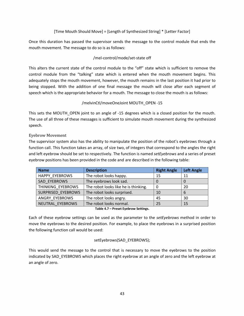
43
[Time Mouth Should Move] = [Length of Synthesized String] * [Letter Factor]
Once this duration has passed the supervisor sends the message to the control module that ends the
mouth movement. The message to do so is as follows:
/mel-control/mode/set-state off
This alters the current state of the control module to the “off” state which is sufficient to remove the
control module from the “talking” state which is entered when the mouth movement begins. This
adequately stops the mouth movement, however, the mouth remains in the last position it had prior to
being stopped. With the addition of one final message the mouth will close after each segment of
speech which is the appropriate behavior for a mouth. The message to close the mouth is as follows:
/melvinCtl/moveOneJoint MOUTH_OPEN -15
This sets the MOUTH_OPEN joint to an angle of -15 degrees which is a closed position for the mouth.
The use of all three of these messages is sufficient to simulate mouth movement during the synthesized
speech.
Eyebrow Movement
The supervisor system also has the ability to manipulate the position of the robot’s eyebrows through a
function call. This function takes an array, of size two, of integers that correspond to the angles the right
and left eyebrow should be set to respectively. The function is named setEyebrows and a series of preset
eyebrow positions has been provided in the code and are described in the following table:
Name Description Right Angle Left Angle
HAPPY_EYEBROWS The robot looks happy. 15 11
SAD_EYEBROWS The eyebrows look sad. 0 0
THINKING_EYEBROWS The robot looks like he is thinking. 0 20
SURPRISED_EYEBROWS The robot looks surprised. 10 6
ANGRY_EYEBROWS The robot looks angry. 45 30
NEUTRAL_EYEBROWS The robot looks normal. 25 15 Table 4.7 – Preset Eyebrow Settings.
Each of these eyebrow settings can be used as the parameter to the setEyebrows method in order to
move the eyebrows to the desired position. For example, to place the eyebrows in a surprised position
the following function call would be used:
setEyebrows(SAD_EYEBROWS);
This would send the message to the control that is necessary to move the eyebrows to the position
indicated by SAD_EYEBROWS which places the right eyebrow at an angle of zero and the left eyebrow at
an angle of zero.

44
Point to a Location
The supervisor also has the ability to have the robot point to a specific location. The following is the
format for sending a message to indicate what location the robot should point to:
/melvinCtl/point [Head Center] [Rotation] [Point Location] [Robot’s hand location] [Wait Time]
There are several pieces of information necessary for the message to indicate a location for the robot to
point to. First, there is the location of the center of the robot’s head. This comes in the form of two
integers corresponding to the x and a y coordinate of the center of the robot’s head. Next is the rotation
degrees which is the number of degrees the robot is rotated in relation to the table and this comes in
the form of a single integer. The point location comes in the form of three integers corresponding to the
x, y, and z coordinates for the location where the robot is going to point. The robot’s hand location
comes in the form of two integers which correspond to the x and y coordinates for the location of the
robot’s hand. Finally, the wait time comes in the form of a single integer which is the number of
milliseconds the robot should pause while pointing at an object before removing his hand. Once this
message is sent the robot will move his hand to indicate the given location.
Turn Taking
The supervisor’s main task is to control the turn taking of the overall kitchen scenario. This involves
receiving information from the vision system and then relaying the pertinent information to the control
system. Most importantly are the two turns: the Human’s turn and the Robot’s turn. These turns are
described below.
Human’s Turn
The Human turn begins when a Human hand enters and is visible, and ends once the hand is no longer
visible so long as it indicated an object. The supervisor keeps track of each object that is being pointed
to by any hand that is visible within the system and so long as the object has been pointed to past the
minimum point duration then the supervisor flags this item as indicated. Once the hand is no longer
visible the Human’s turn is over and the Robot’s turn begins. The Human’s turn continues so long as no
object has been identified.
Robot’s Turn
The Robot turn begins once the Human hand, after indicating an object, is no longer visible, and the
Robot turn ends once the Robot hand, after indicating the same object, is no longer visible. The Robot
turn tells the robot to point at the same object that was indicated during the Human turn and continues
to update the hand position until it is within a certain threshold of the object. The Robot turn then
pauses a set point duration and then tells the Robot to return to the home position. Once the Robot’s
hand is no longer visible the Robot’s turn is over, and the Human’s turn begins again. The Robot’s turn
continues so long as the Robot’s hand is not within a threshold of the given object.
4.3.4 melIState
The melIState interface encapsulates the concept of a state within the supervisor module. It provides
functionality to determine if a state has been previously visited, to determine if a specified duration of
45
time has passed since the state was first entered, and the ability to change states. These tasks are
described below.
Visited
In order to determine if a state has previously been visited two functions exist. The first function
establishes that a state has been visited and it is called upon entering the state. This function also stores
the time when the state was entered for use later. To visit a state the visit method is called. In order to
determine if a state has already been visited use the visited method this returns a Boolean indicating
whether or not the state has been visited.
Duration Passed
In order to determine if a certain duration of time has passed since a state was entered, the
durationPassed method exists. This method takes an integer value which corresponds to the number of
milliseconds that should have passed and returns true if that amount of time has passed since the state
was initially entered.
Changing State
In order to change from one state to another the changeState method exists. This method takes a
pointer to the supervisor system which enables the state to analyze the system to determine which
states it should transition to. This method returns the state that was transitioned to.
Concrete Look States
The supervisor module makes use of many concrete melIState objects each works together to keep track
of the state of the robot’s eyes. This determines where the robot is looking at any given time as well as
where the robot should look depending on the current settings of the supervisor. The following diagram
depicts each of the concrete look states along with their corresponding transitions.

46
Figure 20 – Concrete Look State Diagram
melGlanceLookState
The Glance Look State is entered any time that the robot is glancing up from the table to look at the
human. When this state is entered the supervisor tells the control module to have the robot look at the
human. The Glance state is cycled through until the duration associated with the length of time the
robot takes to glance has passed. Once the glance duration has passed the robot returns to the Table
Look State.
melHumanLookState
The Human Look State is entered any time that the robot is looking at the human for a period of time
longer than a glance. When this state is entered the supervisor tells the control module to have the
robot look at the human. In the event that the Human look state does not change to another state after
the inactive duration has passed, we enter the Uninterested Look State. In the event that a Human Hand
is present in the environment, the Table Look state is entered. In the event that the robot is pointing at
an object on the table, we enter the Table Look State. When the supervisor module runs for the first
time the robot starts in the Human Look State.
melTableLookState
The Table Look State is entered any time that the robot is looking at the table or an object on the table.
When this state is entered the supervisor tells the control module to have the robot look at the table. In
the event that a human hand is visible on the table for longer than the set maximum visible hand
duration, we enter the Glance Look State and the robot glances at the human. In the event that there

47
are no visible hands in the environment, we enter the Human Look State. In the event that the robot has
met the error term for the object he is pointing at, we enter the Glance Look State.
melUninterestedLookState
The Uninterested Look State is entered any time there is no activity for a specified inactive duration.
When the Uninterested Look State is entered the supervisor does not send the control any specific
instructions related to where the robot should look. In the event that a human hand is present, we enter
the Human Look State.
Concrete Turn States
The supervisor module makes use of many concrete melIState objects each working together to keep
track of the current state of the overall interaction between the robot and the human. This module
determines whether it is currently the human’s turn or if it is the robot’s turn while also taking into
account the different parts of each turn. The following diagram depicts each of the concrete states along
with their corresponding transitions.
Figure 21 – Concrete Turn State Diagram
melFeedbackState
The Feedback State is entered anytime the robot is moving his arm to point at a specific object. When
this state is entered the supervisor sends the control module instructions to have the robot point at a
specific object on the table. In the event that the robot points at the object, we enter the Pointing State.
In the event that a human hand appears, we enter the Human Hand State.

48
melHumanHandState
The Human Hand State is entered anytime the human is pointing at objects on the table. In the event
that the human hand is no longer pointing at any objects on the table, we enter the Initial State.
melInactiveState
The Inactive State is entered whenever there is no activity in the environment for a specific inactive
duration. In the event that a human hand appears, we enter the Initial state.
melInitialState
The Initial State is entered whenever neither the robot nor the human are executing their turns. In the
event that there is no activity in the environment for the specified inactive duration, we enter the
Inactive State. In the event that a human hand appears, we enter the Human Hand state. In the event
that an object has been indicated by the human, we enter the Feedback State. When the supervisor
begins for the first time the robot starts in the Initial State.
melPointingState
The Pointing State is entered at any time when the robot is currently pointing at an object on the table.
This state continues until a specified point duration has passed and then enters the Robot Hand State.
This allows the robot to point at an object for a specific amount of time prior to returning his hand to
the home position.
melRobotHandState
The Robot Hand State is entered at any time the robot is removing his hand from the table after pointing
at a specific object on the table. In the event that the robot hand disappears from the environment, we
return to the initial state. In the event that a human hand appears, we return to the Human Hand state.

49
4.4 Vision Module
The vision module is responsible for analyzing and collecting information regarding frames of video
being received through a camera. Once these objects have been detected the vision module is
responsible for relaying the collected objects to the supervisor module through an open socket
connection. The overall architecture of the vision module is described below including each individual
component of the module.
4.4.1 UML Diagram
The vision module contains many objects which are responsible for working together in order to
complete vision related tasks. The vision module contains a configuration object responsible for loading
and storing settings contained within a configuration file. The module also has a socket object
responsible for sending information from the vision module to the supervisor module. A drawing object
also exists in order to draw specified objects onto a frame while the vision controller object is
responsible for loading and displaying frames on the screen. Detection strategies exist which provide the
ability to detect specific objects from a frame or from a series of known blobs. The UML diagram for the
vision module is depicted in the image below.

50
Figure 22 – Vision module UML Diagram
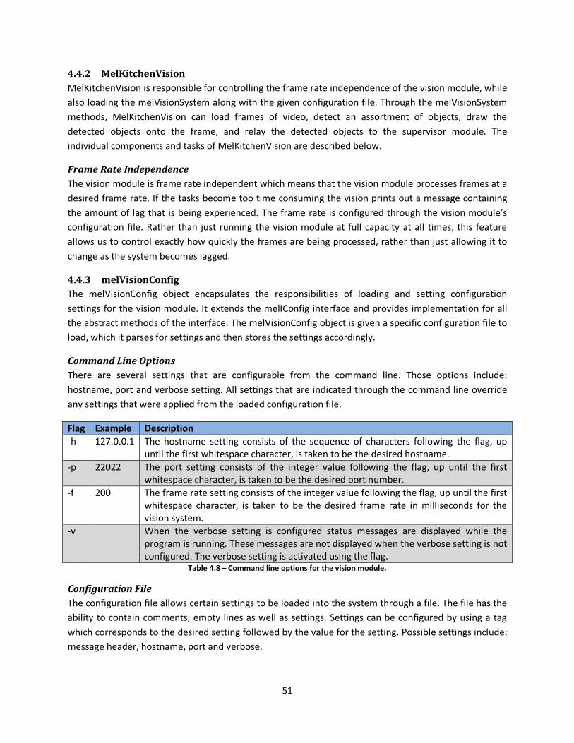
51
4.4.2 MelKitchenVision
MelKitchenVision is responsible for controlling the frame rate independence of the vision module, while
also loading the melVisionSystem along with the given configuration file. Through the melVisionSystem
methods, MelKitchenVision can load frames of video, detect an assortment of objects, draw the
detected objects onto the frame, and relay the detected objects to the supervisor module. The
individual components and tasks of MelKitchenVision are described below.
Frame Rate Independence
The vision module is frame rate independent which means that the vision module processes frames at a
desired frame rate. If the tasks become too time consuming the vision prints out a message containing
the amount of lag that is being experienced. The frame rate is configured through the vision module’s
configuration file. Rather than just running the vision module at full capacity at all times, this feature
allows us to control exactly how quickly the frames are being processed, rather than just allowing it to
change as the system becomes lagged.
4.4.3 melVisionConfig
The melVisionConfig object encapsulates the responsibilities of loading and setting configuration
settings for the vision module. It extends the melIConfig interface and provides implementation for all
the abstract methods of the interface. The melVisionConfig object is given a specific configuration file to
load, which it parses for settings and then stores the settings accordingly.
Command Line Options
There are several settings that are configurable from the command line. Those options include:
hostname, port and verbose setting. All settings that are indicated through the command line override
any settings that were applied from the loaded configuration file.
Flag Example Description
-h 127.0.0.1 The hostname setting consists of the sequence of characters following the flag, up
until the first whitespace character, is taken to be the desired hostname.
-p 22022 The port setting consists of the integer value following the flag, up until the first
whitespace character, is taken to be the desired port number.
-f 200 The frame rate setting consists of the integer value following the flag, up until the first
whitespace character, is taken to be the desired frame rate in milliseconds for the
vision system.
-v When the verbose setting is configured status messages are displayed while the
program is running. These messages are not displayed when the verbose setting is not
configured. The verbose setting is activated using the flag. Table 4.8 – Command line options for the vision module.
Configuration File
The configuration file allows certain settings to be loaded into the system through a file. The file has the
ability to contain comments, empty lines as well as settings. Settings can be configured by using a tag
which corresponds to the desired setting followed by the value for the setting. Possible settings include:
message header, hostname, port and verbose.

52
Structure
The configuration file has a very basic structure. All lines that begin with a pound (#) character indicate
comments and are ignored by the configuration parser. Lines that are left blank, or do not contain any
characters other than whitespace, are also ignored by the configuration parser. Settings are configured
by using a TAG: VALUE format. The TAG indicates the setting to configure and the VALUE indicates the
value that the setting should be configured to. The TAG must be followed by a single colon which is then
followed by a single space. All TAGs are required to be in uppercase for processing while the VALUEs are
not case sensitive.
Implemented Settings
There are several settings that can be configured from the configuration file. The setting is indicated in
the configuration file in the following format: TAG: VALUE. Where TAG is the name of the setting to be
configured, which must be followed by a colon and then a single space, and VALUE is the value this
particular setting should be configured to. The possible settings are: the message header, the hostname,
the port, the frame rate, the table dimensions and the verbose setting. The following sections describe
how to configure each of these settings.

53
Setting Description
HOST_NAME The hostname setting is configured by using the HOSTNAME tag followed by the
desired value for the hostname setting. The hostname refers to the hostname of
the supervisor machine which is used when connecting and relaying information
to the supervisor.
MESSAGE_HEADER The message header setting is configured by using the MESSAGE_HEADER tag
followed by the desired value for the message header. The message heard is
placed at the beginning of each message sent to the supervisor.
LOG_FILE The log file setting is configured using the LOG_FILE flag followed by the filename
and path where the log file should be saved. This file will be used to store certain
information such as the messages that are sent from the vision to the supervisor
module. Messages are saved to the log file when the Verbose setting is activated.
SERVER_PORT The port number setting is configured by using the PORT tag followed the by the
integer value that you wish the port number to be. The port number refers to the
particular port of the supervisor machine which is used when connecting and
relaying information to the supervisor.
FRAME_RATE The frame rate setting is configured using the FRAME_RATE tag and the intended
integer value following the tag name. The frame rate determines the number of
milliseconds between each cycle of the vision system. For example, a frame rate
setting of 200 milliseconds would mean that the vision cycle would run
approximately five times per second. A frame rate setting of 1000 milliseconds
would mean the vision cycle runs one time per second.
TABLE_WIDTH The table width setting of the table is configured with the TABLE_WIDTH flag
followed by the integer value, in millimeters, that the table width should be
configured to. The table width is the length of the first horizontal edge of the
table closest to the human.
TABLE_HEIGHT The table height is configured using the TABLE_HEIGHT flag followed by the
integer value, in millimeters, that the table height should be configured to. The
table height is the leftmost edge of the table from the human’s point of view.
TABLE_SUB_WIDTH The table sub width flag is configured using the TABLE_SUB_WIDTH flag followed
by the integer value, in millimeters, that the table sub width setting should be
configured to. The table sub width is the length of the horizontal edge furthest
away from the human.
TABLE_SUB_HEIGHT The table sub height flag is set using the TABLE_SUB_HEIGHT flag followed by the
integer value, in millimeters, that the table sub height should be configured to.
The table sub height is the length of the rightmost edge of the table from the
human’s point of view.
VERBOSE The verbose setting is configured by using the VERBOSE flag followed by a value
of either TRUE or FALSE. The value indicates whether the verbose flag should be
enabled, TRUE, or disabled, FALSE. When the verbose setting is enabled status
messages will be displayed in the console while the program is running. These
messages will not be displayed when the verbose setting is disabled. Enabling the
verbose setting also appends messages onto the log file. Table 4.9 – Configuration Settings for the vision module.

54
4.4.4 melVisionSystem
The melVisionSystem encapsulates the responsibilities of the overall vision system. The system contains
configuration objects for loading configuration settings, socket objects for sending and receiving
messages via sockets and system specific properties such as the current table location and all the
currently detected objects. The melVisionSystem is also responsible for performing OpenCV specific
operations for loading and capturing images, creating graphical user interfaces, and performing
transformations on the images. The melVisionSystem provides functionality for all aspects of the vision
system including sending and receiving messages, loading configuration files, loading frames and
capturing camera input as well as detecting all types of objects in the environment.
melSocket
The melISocket object encapsulates the concept of a socket connection between two computers into a
single object. This object is responsible for providing an interface for performing socket related tasks
such as sending and receiving messages as well as connecting to a server or client. Each of these tasks is
described below.
Server Actions
The melISocket object can be used for various server related tasks such as starting a server, listening for
connections, and receiving messages from clients. Each of the functions related to these actions is
described in the sections below.
Starting a Server
In order to set up the server so that clients can connect the melISocket provides the startServer method
which takes an integer that is the port number this server should be bound to. Clients will then need to
know the hostname and port of the server machine in order to properly connect and begin sending
messages. This function binds the socket to the given port number to prepare the socket to begin
listening and accepting connections.
Listening for Messages
In order to allow clients to connect to the open server socket the server socket must be listening for
connections. The melISocket object provides the listen method which enables the server to listen for
incoming connections. Once an incoming connection is established the client is connected to the server
socket and messages can start to be received.
Receiving Messages
In order to receive a message through the established socket connection the melISocket method
provides the receiveMessage method which enables the server socket to receive a message from the
connected client. This function returns the message received as a string which can then be parsed and
the proper action can be taken.
Client Actions
The melISocket object can be used for various client related tasks such as opening a socket connection
to a server, sending a message to a server, and closing the socket. Each of the functions designated to
perform these tasks are described below.
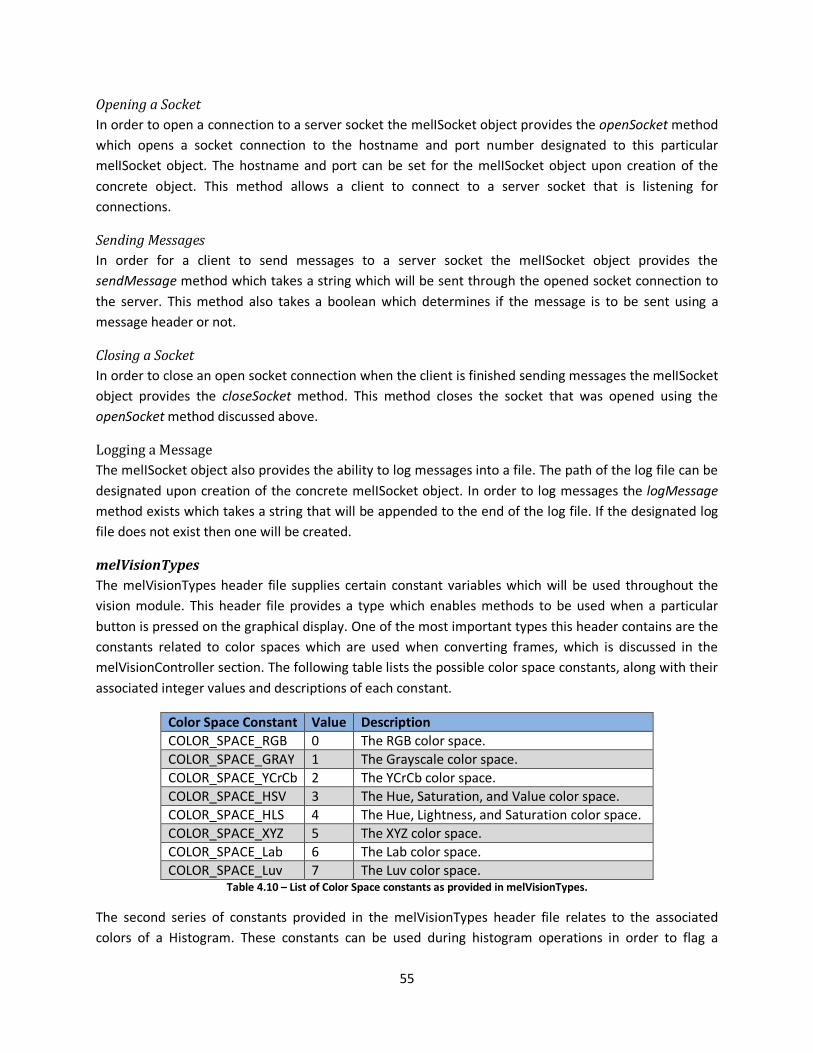
55
Opening a Socket
In order to open a connection to a server socket the melISocket object provides the openSocket method
which opens a socket connection to the hostname and port number designated to this particular
melISocket object. The hostname and port can be set for the melISocket object upon creation of the
concrete object. This method allows a client to connect to a server socket that is listening for
connections.
Sending Messages
In order for a client to send messages to a server socket the melISocket object provides the
sendMessage method which takes a string which will be sent through the opened socket connection to
the server. This method also takes a boolean which determines if the message is to be sent using a
message header or not.
Closing a Socket
In order to close an open socket connection when the client is finished sending messages the melISocket
object provides the closeSocket method. This method closes the socket that was opened using the
openSocket method discussed above.
Logging a Message
The melISocket object also provides the ability to log messages into a file. The path of the log file can be
designated upon creation of the concrete melISocket object. In order to log messages the logMessage
method exists which takes a string that will be appended to the end of the log file. If the designated log
file does not exist then one will be created.
melVisionTypes
The melVisionTypes header file supplies certain constant variables which will be used throughout the
vision module. This header file provides a type which enables methods to be used when a particular
button is pressed on the graphical display. One of the most important types this header contains are the
constants related to color spaces which are used when converting frames, which is discussed in the
melVisionController section. The following table lists the possible color space constants, along with their
associated integer values and descriptions of each constant.
Color Space Constant Value Description
COLOR_SPACE_RGB 0 The RGB color space.
COLOR_SPACE_GRAY 1 The Grayscale color space.
COLOR_SPACE_YCrCb 2 The YCrCb color space.
COLOR_SPACE_HSV 3 The Hue, Saturation, and Value color space.
COLOR_SPACE_HLS 4 The Hue, Lightness, and Saturation color space.
COLOR_SPACE_XYZ 5 The XYZ color space.
COLOR_SPACE_Lab 6 The Lab color space.
COLOR_SPACE_Luv 7 The Luv color space. Table 4.10 – List of Color Space constants as provided in melVisionTypes.
The second series of constants provided in the melVisionTypes header file relates to the associated
colors of a Histogram. These constants can be used during histogram operations in order to flag a

56
detection method to use a specific color. The values of each constant are arranged such that multiple
constants can be used simultaneously. The following table lists the possible histogram color values, their
associated integer value, and a corresponding description.
Histogram Color Constant Value Description
CV_HIST_RED 1 Values associated with the color red.
CV_HIST_ORANGE 2 Values associated with the color orange.
CV_HIST_YELLOW 4 Values associated with the color yellow.
CV_HIST_GREEN 8 Values associated with the color green.
CV_HIST_TEAL 16 Values associated with the color teal.
CV_HIST_BLUE 32 Values associated with the color blue.
CV_HIST_NAVY_BLUE 64 Values associated with the color navy blue.
CV_HIST_PURPLE 128 Values associated with the color purple.
CV_HIST_PINK 256 Values associated with the color pink. Table 4.11 – Histogram Color constants as provided in melVisionTypes.
melVisionController
The melVisionController object is responsible for performing all the video, or image, loading tasks. These
tasks include loading capture from a camera or from a file, loading an image from a file, saving an image
to a file, displaying the current frame of capture in a window and converting frames into different color
spaces.
Capture
There are many tasks directly related to capturing a sequence of video in order to process the frames.
These tasks include: loading capture from a camera, loading capture from a video file, and grabbing the
next frame of capture. These tasks and associated methods are discussed below.
Camera
In order to capture a stream of video from a camera device the melIVisionController object provides the
loadCaptureFromCAM method which takes an integer representing the camera which should be used.
This function enables the video to be streamed from the camera device allowing frames of the capture
to be subsequently grabbed and processed.
Video File
In order to capture a stream of video from a pre-existing video file the melIVisionController object
provides the loadCaptureFromFile method which takes a string corresponding to the path where the
video file is located. This function enables the video to be streamed from the video file allowing frames
of the capture to be subsequently grabbed and processed.
Grabbing Frames
Once capture has been loaded, either from a camera or from a video file, the next step is to grab
subsequent frames of the capture in order to be used for processing purposes. The melIVisionController
object provides the grabNextFrame method which loads the next frame into the current frame of the
vision controller object.

57
Accessing the Current Frame
In order to access the current frame for the vision controller object the melIVisionController object
provides the getCurrentFrame method which returns the frame that is currently loaded into the object.
The current frame can be loaded in a variety of ways, such as through the process of grabbing frames of
capture, or by loading a static image into the vision controller.
Converting Frames
Many times it is useful to obtain a frame in a specific color space. The melIVisionController object
provides the convertFrame method which takes the frame which should be converted and an integer
representing the color space to convert the frame into. The associated color space constants are
provided in the melVisionTypes header file.
Loading Images
In order to load a single image as a frame the melIVisionController object provides the
loadImageFromFile method which takes a string corresponding to the path where the image file is
located as well as an integer representing the color space this frame should be loaded into. This function
loads the image located at the given path into the current frame of this object.
Saving Images
Another useful feature provided by the melIVisionController is saving frames in a specific location. The
vision controller provides the ability to set the path where frames should be saved, and also to save the
frame that is currently loaded into the object. In order to set the path where images should be saved the
setSavedImagesPath method exists which takes a string parameter which is the path to where saved
frames will be located. The saveImage method is responsible for actually saving the currently loaded
frame.
Displays
The melIVisionController provides several functions responsible for handling the graphical components
of displaying information on a screen. These tasks include: creating and destroying windows, creating
buttons within a window, and to exit the window in the event of a key press. These tasks and their
associated functions are described below.
Windows
The melIVisionController object provides two means for creating windows and displaying frames within
the windows. The function that displays the windows is called showDisplay. This function can be called
with just a string corresponding to the window’s desired title, or it can also include a frame to be
displayed within the frame. If no frame is included as a parameter the window will contain the currently
loaded frame within the vision controller object. Otherwise, the frame passed as a parameter will be
visible within the frame. In order to destroy a previously created window the melIVisionController
provides the destroyDisplay method which takes the title of the window that should be destroyed.
Buttons
The melIVisionController provides the ability to create a button within a preexisting window. The
function that creates the button is called createButton. It takes the name of the button, the title of the

58
containing window, the button’s caption, the width of the button, and a callback function which will be
executed in the event that the button is pressed. This function allows a button to be created within the
window which performs a designated task when the button is pressed.
melPoint
The melPoint object encapsulates a single point in the environment. The key features of a point are the x
and y coordinates of the point which can be represented in any the measurement of the coordinate
system. For example, a point in the image plane would be in pixels while a point in the true environment
would be represented in millimeters, or an equivalent measurement.
melIObject
The melIObject interface provides an interface for all objects that can exist in the environment. The
objects extend this interface and provide their own objet specific implementation. The possible objects
include: blobs, boxes, circles, rectangles, squares, lines, tables, hands and heads.
Attributes of melIObject
Every instance of the melIObject has specific properties and methods for using these properties. These
properties include: point duration, color, and last point time. Their uses are described below.
Point Duration
The point duration property corresponds to the number of frames that an object has been pointed to by
the human. This attribute allows us to keep track of which objects were pointed at the most. The point
duration can be accessed by using the getPointDuration method, and the point duration for an object
can be reset to zero by calling the cleraPointDuration method. The point duration is increased when the
pointAt method is called.
Last Point Time
The last point time property stores the number of ticks that corresponds to the last time the object was
pointed at by the human. This attribute allows us to determine which objects were pointed at most
recently. The last point time is set when the pointAt method is called for an object. The last point time
can also be accessed by using the setLastPoint and getLastPoint methods. Using the
getTimeSinceLastPoint method will return the number of ticks that have passed since the object was last
pointed at by the human.
Color
Each instance of the melIObject interface contains a property which contains the current color of the
object. This attribute is used in order to store the color of the object in order to use it later when
recognizing plates within the supervisor module. Color is stored as a string where “Blue” or “Red” would
be two possible values for the color of an object.
Message Structure
Each message relayed to the supervisor contains the number of objects followed by the information
pertaining to each object. The message is sent and received in the form of a string. This structure allows
the supervisor to easily receive and parse the message for all the detected objects and then it can

59
proceed from there. The message for each object contains the information necessary for the supervisor
to recreate the object. The structure for each object is described in the following table.
Object Description of Message Structure
melBlob BLOB POINTED_AT TOP_LEFT_X TOP_LEFT_Y WIDTH HEIGHT AREA
melBox BOX POINTED_AT CENTER_X CENTER_Y WIDTH HEIGHT ANGLE
melCircle CIRCLE POINTED_AT CENTER_X CENTER_Y RADIUS COLOR
melHand HAND POINTING CENTER_X CENTER_Y ANGLE WIDTH HEIGHT
melHead HEAD CENTER_X CENTER_Y
melLine LINE POINTED_AT POINT_ONE_X POINT_ONE_Y POINT_TWO_X POINT_TWO_Y
melSquare SQUARE POINTED_AT TOP_LEFT_X TOP_LEFT_Y SIZE COLOR
melRect RECT POINTED_AT TOP_LEFT_X TOP_LEFT_Y WIDTH HEIGHT COLOR
melRobotHand ROBOTHAND CENTER_X CENTER_LEFT_Y ANGLE WIDTH HEIGHT
melTable TABLE TABLE_WIDTH TABLE_HEIGHT TABLE_SUB_WIDTH TABLE_SUB_HEIGHT
CORNER_BOT_RIGHT_X CORNER_BOT_RIGHT_Y MtoP. Table 4.12 – Message Structure for the vision module objects.
melCircle
The melCircle object encapsulates the characteristics of a circle in the environment. The important
features of a circle are the x and y coordinates of the center of the circle, the circle’s radius and whether
or not the circle is currently being pointed at. The circle’s string representation also includes the color of
the particular circle.
melRect
The melRect object encapsulates all the key characteristics of a rectangle in the environment. The
characteristics of interest are the x and y coordinates of the top left corner, the width and height of the
rectangle and whether or not the rectangle is currently being pointed at. The rectangle’s string
representation also includes the color of the particular rectangle.
melSquare
The melSquare object encapsulates all the key characteristics of a square in the environment. The
characteristics of interest are the x and y coordinates of the top left corner, the size of the square and
whether or not the square is currently being pointed at. The square’s string representation also includes
the color of the particular square.
melHand
The melHand object encapsulates all the key characteristics of a human hand in the environment. The
characteristics of interest are the x and y coordinates of the top left corner, the size of the hand, the
rotation angle of the hand and whether or not the hand is currently pointing at an object.
melRobotHand
The melRobotHand object encapsulates all the key characteristics of a Robot hand in the environment.
The characteristics of interest are the x and y coordinates of the top left corner, the size of the hand, the
rotation angle of the hand and whether or not the hand is currently pointing at an object.
60
melHead
The melHead object encapsulates all the key characteristics of a head in the environment. The
characteristics of interest are the x and y coordinates of the center position of the head object.
melLine
The melLine object encapsulates all the key characteristics of a line in the environment. The
characteristics of interest are the x and y coordinates for the two endpoints of the line.
Distance from line
The melLine object provides the ability to determine the distance between the given line and a point.
This method returns an integer that is the distance between the line and the point. This method is called
using the distanceFromLine call.
melBlob
The melBlob object encapsulates all the characteristics of a blob in the environment. The characteristics
of interest are the coordinates for the top left of the blob, the width, the height and the area of the
blob.
melBox
The melBox object encapsulates all the key characteristics of a bounding box in the environment. The
characteristics of interest are the coordinates for the center of the blob, the width, the height and the
central angle of the bounding box.
melTable
The melTable object encapsulates a table object within the environment. The table contains all the
currently known coordinates for each corner of the table as well as the width and heights of each table
segment in millimeters which can be loaded through the configuration file.
Setting the Table
Using the configuration settings corresponding to the table dimensions the melTable object is
responsible for storing these values and using them to detect the position for each corner of the table.
These measurements are in millimeters.
Setting the Millimeter to Pixel Conversion Factor
In addition to storing the values for the length of each segment of the table the melTable object also
stores the millimeter to pixel conversion factor which can be set using the table’s setMTOP method. This
conversion factor is used when determining the coordinates of each of the corners of the table.
Discovering all points of the table
Once the lengths of each segment of the table are set and the millimeter to pixel conversion factor is
known the corners of the table can be detected by using the table’s findTable method. This method
takes the x and y coordinates, in pixels, of a specified corner of the table. Using these coordinates it
locates the position, in pixels, for each of the remaining corners of the table through use of the known
millimeter lengths of each segment of the table as well as the millimeter to pixel conversion factor. Once
the coordinates for each corner are located the table stores their locations.
61
Point on the Table
The melTable object provides a method for determining if a given point falls within the boundary of the
table. It returns true if the given point is on the table, false otherwise. This method is used by calling the
onTable method. The onTableExtension method also exists to determine if a point falls within the table
extension.
Table Rectangle
The melTable object provides the getTableRect method for returning the rectangle that corresponds to
the front of the table. This rectangle is made up of the following corners of the table: bottom right,
bottom left, and middle right corner.
Table Extension Rectangle
The melTable object provides the getTableExtRect method for returning the rectangle that corresponds
to the table extension. This rectangle is made up of the following corners of the table: middle left, top
left, and top right. The table extension is not included in the regular table rectangle.
Robot Rectangle
The melTable object provides the getRobotRect method for returning the rectangle that corresponds to
the place in the frame where the robot will appear. This rectangle is made up of the following corners:
middle right, middle left and top left.
melObjectSeq
The melObjectSeq encapsulates a sequence of objects in the environment. Because it is implemented to
store the melIObject interface the melObjectSeq can store any number of objects of various types so
long as those objects implement the melIObject interface. The melObjectSeq provides functionality to
easily add and remove objects from the sequence as well as retrieving a given object and determining
the number of objects that exist within the sequence.
Adding Objects
The melObjectSeq method addObject allows a given object to be added to the preexisting sequence so
long as the object extends the melIObject interface. The object will be added to the end of the sequence
and can be easily accessed through use of melObjectSeq’s built in methods.
Removing Objects
The melObjectSeq method removeObject allows an object to be removed by supplying the index that
corresponds to the object that should be removed. After the method is called the melObjectSeq will no
longer contain the object, unless the index supplied was out of the bounds of the sequence then the
sequence will be unchanged.
Retrieving Objects
The melObjectSeq provides a method getObject that accepts an index of an object that is to be returned
and then it returns the object at the requested index. If an invalid index is supplied a NULL value is
returned.
62
Merging Two Sequences
The melObjectSeq object provides a method mergeSeq that takes a pointer to another melObjectSeq as
a parameter. The output of this method is to combine the two sequences into one sequence but it does
not keep duplicate copies of objects. When choosing objects to retain in the new sequence this method
keeps the most recent point time for the object and also keeps the number of times the object was
pointed at. This is useful when the supervisor is attempting to determine which object was indicated by
the human.
melCalibrate
The melCalibrate object is responsible for calibrating the vision module to the real-time environment.
Once the module has been calibrated, each corner of the table can be detected and pixel coordinates
can then be converted into the corresponding coordinate system.
Calibration
In order to calibrate the module to the environment the melCalibrate object uses blob detection to
detect the table. Instead of using pixels as the unit of measurement for the system, millimeters were
chosen. Because all of the values found for measurements in the OpenCV system used pixels we had to
convert all the values to millimeters to use with the control system. By finding the left and right edges
of the table using blob detection the millimeter to pixel conversion value was easy to compute. The
pixel length of the table was divided by the millimeter length of the table to give us the value which is
labeled MtoP. The following formula explains how to calculate MtoP:
MtoP = (table pixel width) / (table millimeter width)
The melCalibrate object provides the calibrate method which takes the current frame and the table
width in millimeters as parameters and calibrates the module to the environment.
Converting Coordinates
Once the module has been calibrated to the environment, the other responsibility of the melCalibrate
object is to provide the ability to convert coordinates from a pixel coordinate system into the millimeter
coordinate system described in Section 3.2.1. The melCalibrate object has the ability to convert a
melPoint, a melIObject, or a melObjectSeq into the millimeter coordinate system. The
convertToCoordinate method takes two melPoint objects where one is the point to be converted and
the other is the pixel coordinates for the center of the new coordinate system. The convert method
takes a melIObject and the melPoint corresponding to the pixel location of the center of the new
coordinate system and returns the converted melIObject. The convertSeq method takes a melObjectSeq
and a melPoint corresponding to the pixel location of the center of the new coordinate system and
returns the converted melObjectSeq. Using these methods any objects detected within the environment
can easily be converted to the desired coordinate system.
melDrawObject
The melDrawObject is responsible for drawing a given melIObject onto the current frame. It contains a
static method DrawObject and DrawSeq which take a melIObject and a melObjectSeq respectively and
draw the objects given onto the current frame. The melDrawObject object currently supports drawing

63
the following classes: melBlob, melBox, melCircle, melHand, melHead, melRect, melRobotHand,
melSquare, melTable.
melDetectionStrategy
The melDetectionStrategy is an interface which provides the common functionality of detection
strategies for objects in the environment. It provides the ability to set a threshold, offset, and mask for
the concrete detection strategies while providing the ability to implement the concrete strategies to
detect the objects intended. The uses and concrete detection strategies are described below.
Threshold
It is useful to be able to set the threshold values which can be used during different detection
algorithms. The setThreshold method and the getThreshold methods can be used to set and get the
threshold values for a particular concrete melIDetectionStrategy object. Using the detection strategy
threshold values allows detection algorithms to tweak the selectivity of their processing simply by
altering the threshold values.
Offset
It is also useful to be able to apply an offset to the coordinates of any of the objects detected within a
particular detection strategy. In the event that these objects are detected within a small subsection of a
frame the coordinates will be in relation to that smaller region rather than the whole image. The offset
allows these coordinates to be converted into the section of image that is desired. The setOffsetX,
setOffsetY methods are used to set the offset values for both the x and y coordinates respectively while
the getOffsetX, and getOffsetY methods are used to retrieve the current offset values for the x and y
coordinates respectively.
Mask
When performing detection strategies it is often necessary to view the result of the operations that are
being performed on the frame. In order to do this the melIDetectionStrategy object provides a mask
property which enables the detection strategy to store a frame at any state in order to view it later
which will allow the result of certain operations to be seen. The getMask and setMask methods allow
the mask to be retrieved and to be stored.
Detecting Objects from a Frame
The melIDetectionStrategy interface provides the FindObjects method that takes a frame as a parameter
and returns a sequence of objects. When implemented this function returns the sequence that contains
all of the objects that were detected within that particular frame.
Detecting Objects from Blobs
The melIDetectionStrategy interface provides the FindObjectsFromBlobs method that takes a frame, a
sequence of blobs, and the region of interest where the blob appears within the frame. When
implemented this function returns a sequence of objects that were detected from the given blobs. This
allows previously detected blobs to be narrowed down into specific objects.
64
Updating Objects
The melIDetectionStrategy interface provides the UpdateObject method which takes a frame, and a
single melIObject. When implemented this method returns the same melIObject that was passed as a
parameter, however, the properties of that object will be updated to reflect the changes to the object
within the frame. For example, if the object changed position or size these changes would be reflected
in the returned melIObject.
melBlobStrategy
This detection strategy is responsible for detecting blobs within a given frame. It provides the
implementation to detect blobs from a frame and return the detected blobs while applying the
designated offset and threshold values. The mask used by the blob detection process is stored in the
mask property of the detection strategy.
melHandStrategy
This detection strategy is responsible for the detection of human hands within a given frame. While it
provides implementation to detect any human hands within a frame, it also enables the detection of
human hands from a series of blobs. This detection strategy makes use of the offset properties.
melHeadStrategy
This detection strategy is responsible for detecting the center of the robot’s head from within a frame. It
provides the implementation to detect the center of the head from within a frame which it will return as
a sequence of objects containing only the head object that was detected. This detection strategy makes
use of the offset properties.
melPlateStrategy
This detection strategy is responsible for detecting plates from within a frame. It provides the
implementation to detect plates from within a frame which it will return as a sequence of objects
according to the number of plates that were detected. This detection strategy makes use of the offset
properties as set prior to detecting the plates.
melRobotHandStrategy
This detection strategy is responsible for detecting robot hands in the environment. It provides the
implementation to detect robot hands from a sequence of blobs which it will return as a sequence of
objects containing the number of robot hands it detected. This detection strategy makes use of the
offset properties as well as the mask property. The mask is used during the detection process and
should thus be set to the mask returned by the blob detection process used to detect the blobs that are
being parsed for robot hands.
melSteelRodStrategy
This detection strategy is responsible for detecting the orientation of the robot through detecting the
steel rod that protrudes from the back of the robot. This strategy provides the implementation to detect
the steel rod from within a frame, or from a sequence of blobs. The detected steel rod will be returned
as a sequence of objects containing a melBox corresponding to the steel rod. This detection strategy
makes use of the offset properties.
65
5 Human-Human Study In this part of the MQP, a study was undertaken with two humans to observe how they interacted. The
study required that the two people act out a scenario in the kitchen, where one served as the instructor
who taught the other, serving as the student, how to make canapés. This scenario was chosen because
it represents a significant number of different types of gesture interactions. The kitchen scene was also
focused on due to the grant that is funding the project. The two people are filmed, and then the videos
were studied to learn how the interaction between two people really worked. The question was then
asked whether people look at an object when it is pointed to or when its name is spoken.
The data gathered from this study will allow us to design a natural human-robot interaction. We will
design and implement the interaction by adding code to the robot so that it mimics the results found in
this study. The results can then be verified through testing, in another study, with human beings and
the robot. This second study will develop the field of human-robot interaction so that one day we will
be able to interact with robots in a more natural way.
5.1 Setup
In order to study the interaction, a specific setup was required to include all the different interaction
techniques. In Figure 23 below, the tables are setup in an L shape in order to encourage the use of
multiple areas of the tables. This setup also allowed for different parts of the study to occur in different
areas on the table. The instructor sat on one side of the table and the student on the other, again to
facilitate the ease of how the two people act.

66
Figure 23 - Table Layout
5.1.1 Instructor
The instructor is signified above by the red square with thatched lines and pointed to by the “Instructor”
arrow. The instructor sits in this location so that he/she is able to prepare items on the side table.
There are two instructors during the study. The first instructor is the person who is running the study to
teach the first participant. The second instructor is the first participant that was taught so that this
person can teach the second participant. This person’s job is simply to teach the student how to make
the canapés during the study.
5.1.2 Student
The student is signified above by the red square with thatched lines and pointed to by the “Student”
arrow. The student’s role in the interaction is to learn how to make the canapés and then prepare
them. The first student is the first participant who learns from the person running the study, and the
second student is the second participant who learns from the first participant. This person must only
prepare the canapés and so this person sits in front of a single table with all of the needed ingredients in
front of him or her.
Student
Instructor
67
5.1.3 Middle Table
The middle table contains the ingredients needed for canapés. On the left side in front of the student
the paper towels, utensils, crackers, and spreads. In this way the student can start on the left when they
make the canapé and work to the right. In the center is where the shared workspace is located so that
the instructor and student can work on the same items. Finally on the right of the student is where the
toppings are located such as green olives, black olives, pimientos, and raisins.
5.1.4 Side Table
On the side table, off to the right of the instructor when he/she is sitting down, is where the plate
components are located. The plate, doilies, and paprika are located on the side table so that the
instructor prepares this part off to the side. In this way the parts of the study are separated by type to
again facilitate the interaction.
5.1.5 Cameras
In the above figure the blue and dark blue circles represent where the cameras used to film the
participants are located. The dark blue camera points towards the instructor with the view as
approximated by the two dark blue lines extending from the center of the circle. The camera that faces
the student is signified in blue and has the view as signified by the blue lines protruding from the center
of the circle.
5.2 Activity
During this study an instructor teaches a student how to make canapés. The instruction is done by the
person running the study first, to teach one of the participants how to make the canapés, and then the
first participant teaches the second participant. The interaction is done in four steps, where the activity
is first introduced, then the instructor and student both make one canapé, the student the prepares the
remaining necessary canapés, and finally the instructor arranges the completed canapés on a plate.
5.2.1 Introduce Activity
When the instructor introduces the activity, he/she explains how a canapé is made through verbal
communication and gestures. The instructor points out the crackers first and explains that they are the
base of the canapé. Next the instructor points out the spread that goes on next, either cream cheese or
hummus. Next the toppings are pointed out which consist of the green olives, black olives, pimientos,
and raisins. Finally the instructor signifies that they will each make a canapé together to enforce the
recipe. This part shows a number of interactions that focus on auditory comprehension.
5.2.2 Make First Two Canapés
To make the first two canapés the instructor has the student take a cracker while the instructor takes a
different type of cracker. Next the student selects the spread and topping in order and applies them to
the cracker. When necessary, the student and instructor each take the different ingredients as they
need them from around the table, and ask for them if he/she can’t reach. This section focuses on
special interaction between the two participants.

68
5.2.3 Student Makes Remaining
During the third section the student makes the remaining five canapés with roughly an equal number of
each type of cracker and any combination of spreads and toppings. During this the instructor explains
how the doily is put on the plate. The instructor does this on the side table so that his/her body is
turned from the student to incorporate interaction where they are not directly facing each other. The
student prepares the remaining canapés in the collaborative space between them.
5.2.4 Prepare Plate
Once the canapés and plate are prepared, the canapés are organized on the plate by the instructor. The
student passes each of the canapés in turn to the instructor to incorporate an interaction where one
person is forced to hand items to the other person. Once the canapés are all on the plate in an
organized fashion the instructor then sprinkles paprika over the canapés to give them more color. If the
person running the study and the first participant are finished, then the person running the study leaves
the room and sends in the second participant to learn how to make the canapés. If both people are
participants, then one leaves to bring in the person running the study to complete the study.
5.3 Investigations
There were many things that we were hoping to find in this study. The first and foremost thing that we
wanted to find was what each person does for hand gestures. Second we wanted to know what people
say in different situations. The final few things that we were interested in were head gestures, body
position, and eye movement. Each of these topics are necessary when studying the way people interact,
however because of the time constraints on this project, the deixis portion, that is, pointing with or
without verbal language, was focused on.
5.3.1 Hand Gestures
Hand gestures are the way that people point or signify something through visual cues. The first way to
signify an object is to point directly at it so that the other person or persons around you know what
object you are referring to. The second thing that people do is to make movements that signify
something that is around them or an action to take by simulating the action with their hands. Both of
these gestures seem to be hardwired into human’s brains by nature. This claim has not been proven yet
by scientific study, but seems used in everyday life.
5.3.2 Verbal Communication
The second large portion of communication between humans is when they speak to one another.
Verbal communication would be significantly less efficient without the other ways of communication.
While this is the most common means of communication, people often ensure they have heard what
the other person has said by asking questions or using another form of communication. If a person has
misunderstood they then clarify what they did not understand so that both people can correctly
accomplish the task they are doing.
5.3.3 Head Gestures
While head gestures are often not thought about, they are often the most telling about what is being
understood and what is not. Humans quickly learn from a young age when someone is understanding

69
them simply by looking at the other person during the interaction. When the other person understands
what is being communicated he/she will nod their head, or present another expression such as raising
their eyebrows, to signify this. When they understand to a degree, but disagree, the person will shake
their head, or provide a quizzical expression, to signify a negative response. Humans also turn their
head to an object that is being referred to, after a certain angle in which they only move their eyes, in
order to look at the object. This minimum angle before humans turn their heads to look at an object is
approximately 15° (Goossens & Van Opstal, 1997).
5.3.4 Body Positions
Basic body positions were also studied, but people tend not to change the angle of their body very often
during interactions in our experiment. This tendency occurs because the majority of the time two
people are talking, they are face to face and do not need to turn their body to reach another object. The
exception to this rule is when two or more people have to face a common object that is in a different
direction than the other person. In this study, the direction change occurs only when the instructor is
preparing the plate on the side table.
5.3.5 Eye Movements
Where a person is looking is also another good indicator of what they are paying attention to. People
look at a person when they are talking to them unless the other person is talking about an object in the
near vicinity. When an object is being talked about, both people have a tendency to look between the
object and the other person as confirmation that both people are understanding each other. Eye
movements also give a sense of how engaged the other person is in the interaction. If the other
person’s eyes are “staring off into space,” the other person is often not paying attention to the
interaction. If one person is looking around to piece instructions together, their looking is evidence of
being engaged in the interaction to the other person.
5.4 Results
Once each experiment was completed the videos were transferred to a computer and annotated using a
program called Elan. Elan can be found at http://www.lat-mpi.eu/tools/elan/. This allowed us to play
the two camera angles together and annotate each time a point gesture was executed by the
participants. We then reviewed the annotations and examined the effective and less effective examples
of these data points. There were a total of 31 times that the participants pointed that were studied.
5.4.1 Studied Point Requirements
There were a number of requirements that were used to determine if a point made by a participant was
an effective point and should be given more scrutiny. Even amongst the data that was scrutinized there
were points that were very effective and those that were less effective. Each point that was scrutinized
had a gesture component and a verbal component to the point. The most effective points also had a
confirmation step, where the participant that was not pointing gave feedback to the participant that
was pointing signifying that he/she understood which object was being referenced.
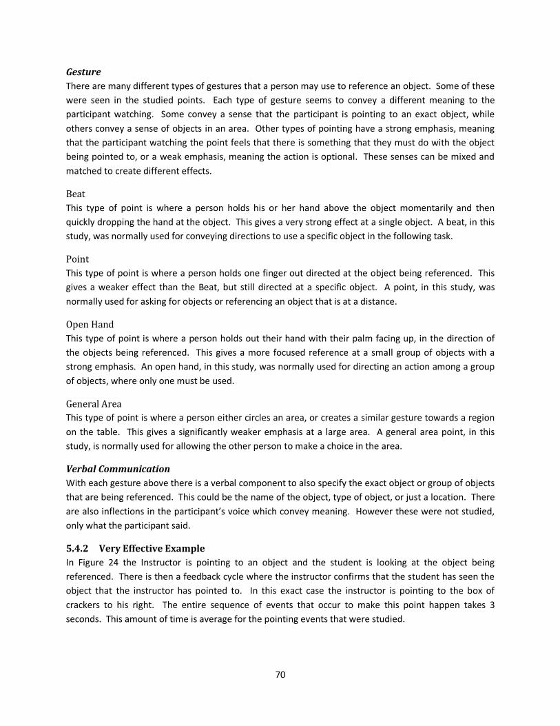
70
Gesture
There are many different types of gestures that a person may use to reference an object. Some of these
were seen in the studied points. Each type of gesture seems to convey a different meaning to the
participant watching. Some convey a sense that the participant is pointing to an exact object, while
others convey a sense of objects in an area. Other types of pointing have a strong emphasis, meaning
that the participant watching the point feels that there is something that they must do with the object
being pointed to, or a weak emphasis, meaning the action is optional. These senses can be mixed and
matched to create different effects.
Beat
This type of point is where a person holds his or her hand above the object momentarily and then
quickly dropping the hand at the object. This gives a very strong effect at a single object. A beat, in this
study, was normally used for conveying directions to use a specific object in the following task.
Point
This type of point is where a person holds one finger out directed at the object being referenced. This
gives a weaker effect than the Beat, but still directed at a specific object. A point, in this study, was
normally used for asking for objects or referencing an object that is at a distance.
Open Hand
This type of point is where a person holds out their hand with their palm facing up, in the direction of
the objects being referenced. This gives a more focused reference at a small group of objects with a
strong emphasis. An open hand, in this study, was normally used for directing an action among a group
of objects, where only one must be used.
General Area
This type of point is where a person either circles an area, or creates a similar gesture towards a region
on the table. This gives a significantly weaker emphasis at a large area. A general area point, in this
study, is normally used for allowing the other person to make a choice in the area.
Verbal Communication
With each gesture above there is a verbal component to also specify the exact object or group of objects
that are being referenced. This could be the name of the object, type of object, or just a location. There
are also inflections in the participant’s voice which convey meaning. However these were not studied,
only what the participant said.
5.4.2 Very Effective Example
In Figure 24 the Instructor is pointing to an object and the student is looking at the object being
referenced. There is then a feedback cycle where the instructor confirms that the student has seen the
object that the instructor has pointed to. In this exact case the instructor is pointing to the box of
crackers to his right. The entire sequence of events that occur to make this point happen takes 3
seconds. This amount of time is average for the pointing events that were studied.
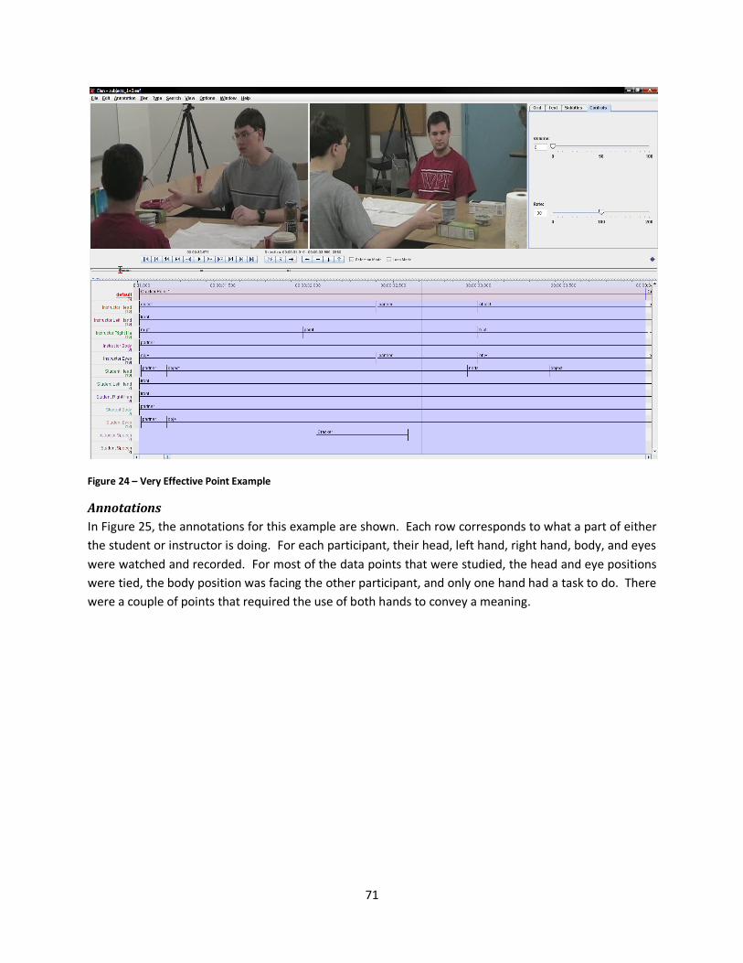
71
Figure 24 – Very Effective Point Example
Annotations
In Figure 25, the annotations for this example are shown. Each row corresponds to what a part of either
the student or instructor is doing. For each participant, their head, left hand, right hand, body, and eyes
were watched and recorded. For most of the data points that were studied, the head and eye positions
were tied, the body position was facing the other participant, and only one hand had a task to do. There
were a couple of points that required the use of both hands to convey a meaning.
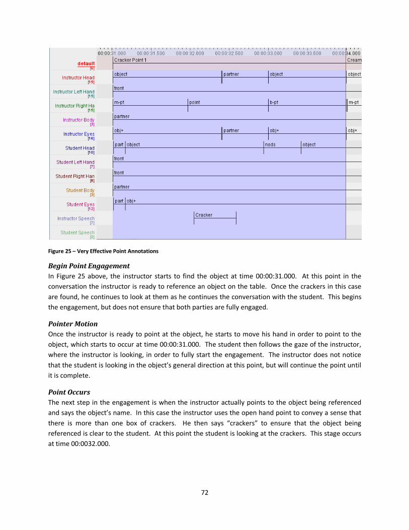
72
Figure 25 – Very Effective Point Annotations
Begin Point Engagement
In Figure 25 above, the instructor starts to find the object at time 00:00:31.000. At this point in the
conversation the instructor is ready to reference an object on the table. Once the crackers in this case
are found, he continues to look at them as he continues the conversation with the student. This begins
the engagement, but does not ensure that both parties are fully engaged.
Pointer Motion
Once the instructor is ready to point at the object, he starts to move his hand in order to point to the
object, which starts to occur at time 00:00:31.000. The student then follows the gaze of the instructor,
where the instructor is looking, in order to fully start the engagement. The instructor does not notice
that the student is looking in the object’s general direction at this point, but will continue the point until
it is complete.
Point Occurs
The next step in the engagement is when the instructor actually points to the object being referenced
and says the object’s name. In this case the instructor uses the open hand point to convey a sense that
there is more than one box of crackers. He then says “crackers” to ensure that the object being
referenced is clear to the student. At this point the student is looking at the crackers. This stage occurs
at time 00:0032.000.

73
Confirmation
For the most effective points, there is a confirmation stage when the instructor has feedback that the
student is looking at the correct object. In this case the feedback is in the form of a nod. In order for
this to occur, the instructor must be looking at the student in order to tell that he nodded. The student
does not necessarily have to know that the instructor is looking at him because this is an optional part of
the engagement. This nod occurs at time 00:00:33.000.
End Point Engagement
Upon completion of the point, or confirmation of the point, there is a disengagement routine that
occurs. This is normally when the instructor or student continues the conversation by responding in an
appropriate manner. In this case the instructor simply moves on to talking about the next item to use in
making the canapés, after noticing the student nod.
5.4.3 Less Effective Example
In Figure 26 below, the instructor is telling the student to select a topping for the canapé, while the
student is finishing putting the spread on the cracker. In the figure it is clear that the instructor has
already started pointing to the objects using both hands. The student is removing her hand from the
knife, after placing it in the cream cheese. This point was fast compared to the other points studied, at
about 2 seconds.
Figure 26 – Less Effective Point Example

74
Annotations
In Figure 27 below, it can be seen that there are more annotations for the video than in the previous
example. This is in part due to the complexity of the situation, where the student must accomplish
another task before moving on. Another reason is that the instructor took less time to point than in the
first example.
Figure 27 – Less Effective Point Annotations
Begin Point Engagement
In this example the instructor starts to search for the objects which she will be pointing to. At the same
time the instructor starts to move her hand to point to the location. The student is holding a knife that
she had previously used to spread cream cheese on the cracker. This means that the two participants
were not already engaged and the instructor had to acquire the student’s attention. This starts at time
00:01:09.000.
Pointer Motion
The start of the pointer motion is actually at the start of the point engagement in this example because
the student is not engaged with the instructor at that point. In this phase the student noticed, in her
peripheral vision that the instructor was attempting to acquire her attention. At the same time the
student was finishing spreading the cream cheese, and placed the knife in the cream cheese for the next
time it was needed. This phase starts at the same time as the begin point engagement.
Point Occurs
When the instructor is pointing, she says topping to enforce the choice. This part starts at time
00:01:09.700. In this case the instructor chose to use her left hand in an open gesture in order to
convey a sense of selection and a general area as opposed to a single object. This is in comparison to
the single point that the first example used. Also, one of the instructor’s hands is kept in front of her so
that if the student looks over, she can find the object by looking directly at the instructor.
75
Confirmation
In this example there is not any direct feedback to the instructor from the student. At time
00:01:10.100 the student finds the area of the objects and looks at two separate objects. The instructor
is looking at the objects as well, and therefore is unable to acquire the feedback. In this case it was less
necessary because of the prior work that they had been doing together.
End Point Engagement
In this case, the end of the point engagement is when the instructor finishes speaking and the student is
looking at the objects being referenced. This ends at time 00:01:10.800, which is when both have their
attention toward the toppings.
5.4.4 Complete Findings
Once the data shown in Figure 28, on the next page, was collected, we were able to answer the question
that was posed above. The “Participants” column states the number of the participants being viewed,
and _1 signifies the first participant is the student and _2 signifies the second participant is the student.
The “Time Stamp” column is where the point can be found in the video. For the “Type” column the
values specified correlate to the types of points found above. To signify if the Looker looked when the
object was pointed to, the name of the object was said, or both, see the “Looks When” column. Finally
the “Looker” and “Pointer” column signify the sex of the individual looking at the point and doing the
point respectively.
Of the 31 points that were collected, 4 points were ignored because the looker looked at the point at
the same time the person pointed and said the name of the object, 23 times the lookers looked when
the object was pointed to, and 4 times the looker looked when the objects name was said. This means
that 74% of the time the lookers looked when the object was pointed to, 13% of the time the lookers
looked when the objects name was said, and 13% of the results were ignored. In this study the lookers
were 5.75 times more likely to look when the object was pointed to as to when the objects name was
said.
While this data is not statistically significant for any of the results, it does give us an insight into what is
most likely the outcome of the question posed. This is that humans are more likely to look at an object
when the pointer points to it, rather than when the pointer says the name of the object. We also
believe that there is no correlation between the type of point and whether the human looks when the
object is pointed to or when the objects name is said. There seems to be a correlation that males point
more often than females, although this could also be a factor of the personalities of the individuals that
made up this study.
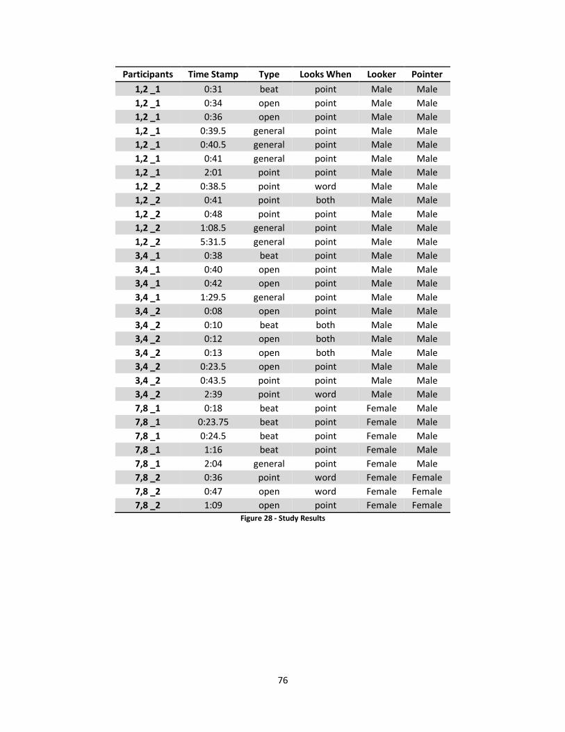
76
Participants Time Stamp Type Looks When Looker Pointer
1,2 _1 0:31 beat point Male Male
1,2 _1 0:34 open point Male Male
1,2 _1 0:36 open point Male Male
1,2 _1 0:39.5 general point Male Male
1,2 _1 0:40.5 general point Male Male
1,2 _1 0:41 general point Male Male
1,2 _1 2:01 point point Male Male
1,2 _2 0:38.5 point word Male Male
1,2 _2 0:41 point both Male Male
1,2 _2 0:48 point point Male Male
1,2 _2 1:08.5 general point Male Male
1,2 _2 5:31.5 general point Male Male
3,4 _1 0:38 beat point Male Male
3,4 _1 0:40 open point Male Male
3,4 _1 0:42 open point Male Male
3,4 _1 1:29.5 general point Male Male
3,4 _2 0:08 open point Male Male
3,4 _2 0:10 beat both Male Male
3,4 _2 0:12 open both Male Male
3,4 _2 0:13 open both Male Male
3,4 _2 0:23.5 open point Male Male
3,4 _2 0:43.5 point point Male Male
3,4 _2 2:39 point word Male Male
7,8 _1 0:18 beat point Female Male
7,8 _1 0:23.75 beat point Female Male
7,8 _1 0:24.5 beat point Female Male
7,8 _1 1:16 beat point Female Male
7,8 _1 2:04 general point Female Male
7,8 _2 0:36 point word Female Female
7,8 _2 0:47 open word Female Female
7,8 _2 1:09 open point Female Female
Figure 28 - Study Results

77
6 Conclusions
6.1 Results
6.1.1 The Video
The video that was created was meant to show some of the capabilities of Melvin. The main camera is
focused on Melvin, the table, and the human subject, while the second camera shows the viewer how
the vision system is tracking the different objects that Melvin sees: the table, Melvin’s hand, human’s
hand, plates, top of Melvin’s head for coordination purposes, the steel rod behind Melvin again for
coordination purposes.
The first few moments of the video show Melvin’s ability to move his arms around the table, once
Melvin is in position he lets the human subject know he is ready to play “the pointing game”. The
human subject then puts the plates randomly on the table. The orange plate is pointed to and Melvin
points to that same plate with his left arm. Note that Melvin tracks the human subject’s hand while it is
in his line of vision. The human subject then moves his hand between plates showing Melvin’s ability to
track the hand and also Melvin’s decision making process of which plate to point at (the plate that is
pointed to the longest). On this run through Melvin was able to identify the plate pointed to, but
because the plate was out of his range he did not point. The last step was to shuffle the plates around
and then point to a plate to show that the vision system tracks the changes in the position of the plates.
Again Melvin was not able to point to the plate, because it was out of range, but once the plate was
moved into his range and the pointing repeated, Melvin pointed to the plate with his right arm. The
video then ends with Melvin saying goodbye. This video can be located at the following link:
http://www.cs.wpi.edu/~rich/hri
6.1.2 Accomplishments
Throughout the course of the project we made various accomplishments toward our overall goal. Each
of the accomplishments is just a small segment of the system necessary to produce the final product.
Our accomplishments for each of the three modules are described below.
Vision Module
Due to the difficult nature of vision-related tasks the majority of our improvements were made within
the vision module. While these accomplishments are simply small steps toward a robust vision system,
they are essential to the overall functionality of the system.
Detection
The main task of the vision module is object detection within the environment. Therefore, the most
improvements and accomplishments were made with respect to the vision module.
Plates
• Real Plates can be used rather than cardboard cutouts.
• The color of plates can be detected.
• The real life position of plate can be determined.

78
• Plates can be tracked as they move across the table.
Hands
• Human hand can be detected without the use of a yellow rubber glove.
• Human hand can be tracked while it moves across the table.
• Robot hands are detected while they move across the table.
• Orientation of human and robot hands are determined.
Environment
• Melvin’s head is detected for determining the position of the robot.
• Melvin’s Steel Rod is detected for determining the robot’s orientation.
• The Table can be detected to establish the constant position of the environment as well as
calibrate the coordination system.
Control Module
The main goal of the control module is to facilitate the manipulation of the robot’s servomechanisms
which enable the robot to perform specific tasks such as pointing or looking at a point. The
accomplishments in respect to the control module are described below.
Inverse Kinematics
• Melvin can point to a real life point with only the X, Y, and Z coordinates as input.
• Melvin is able to point using both his left and his right hand.
• Melvin can determine whether or not the inputted coordinates are out of his range.
Joint Movement
• Any joint can be moved with a call to the joint movement class.
• The angles given for joint movement are real world angles.
Supervisor Module
The main task of the supervisor module is to oversee the turn taking of the interaction between the
human and the robot and thus it is in this area that the most accomplishments, in respect to the
supervisor, were made. These accomplishments are described below.
Speech
• The supervisor can make Melvin speak through synthesis of a string of text.
• The supervisor sends commands to the control module to move the mouth when Melvin is
speaking.
Turn Taking
• The supervisor is able to determine when it is currently the robot’s turn, or when it is the
human’s turn during the interaction.
• The supervisor is able to determine where the robot should look depending on the state of the
interaction.
79
Communication with control module
• The supervisor can successfully retrieve and interpret what is detected in the vision module
through a socket connection.
• The supervisor can successfully communicate with the control module through a socket
connection.
• The supervisor can successfully relay specific actions to the control module, such as: moving the
mouth, pointing at an object, looking at a point, synthesizing speech, and moving any desired
joint.
Diagnostic Module
The diagnostic module is useful for testing specific servomechanisms for problems and also for the
minimum and maximum range of each servomechanism. Therefore, there are not a plethora of
accomplishments with respect to this module; however, the accomplishments are described below.
Manipulating Joint Angles
• The diagnostic module creates a GUI which facilitates the manipulation of each of the robot’s
joints.
• The diagnostic module is able to manipulate the current angle of any of the robot’s joints.
6.1.3 Problems
Throughout the project we encountered many obstacles that temporarily stumped us and halted our
progress until we were able to cope with the particular challenges. These challenges ranged occurred on
both the hardware as well as the software side of the project. The major problems we encountered
during our work are described below.
Broken Gears
Throughout the entire MQP we broke about 9 gears. Many of the times we could not pinpoint the exact
reason why Melvin got a command to move in a way that he would strip a gear in one of his joints.
Luckily it was relatively easy and cheap to replace the gears. A good idea for the future would be to
create a more robust software side fail safe. Currently the right elbow is still broken.
Power Problems
We encountered a problem with Melvin involving erratic movements followed by Melvin shutting down
while attempting to move multiple joints. Sometimes these movements would even result in broken
gears. We found the problem to be that the power supply was not providing enough voltage to Melvin
while moving multiple joints. A temporary solution to the problem was to run Melvin off of two
rechargeable batteries.
Right Arm Potentiometer Slippage
There is currently a problem with Melvin’s right shoulder in which the potentiometer controlling
shoulder pitch will slip significantly when force is applied to Melvin’s arm during movement or his
shoulder is rotated too far while Melvin is off. This problem creates a disparity in the joint angles which
makes angles sent to the Melvin control system not correspond with real world angles. It also affects
the range of motion of Melvin’s shoulder

80
Vision
Creating the vision module proved to be quite a difficult task. Taking into consideration the variable
lighting as well as the inconsistency of movement it was very difficult to produce a reliable system. The
majority of the problems we encountered with the vision were the direct result of either inconsistent
lighting and the reflective properties of objects in the environment. These problems are described
below.
Inconsistent Lighting
We found that at different times of day greatly affected the vision system. What would work early in
the day may not work at night and vice versa. It is not always an issue of insufficient light, but a problem
of objects looking different under different lighting conditions. Until the vision system becomes more
robust it is important to try and keep consistent lighting conditions.
Reflective Plates
At first we used red and blue reflective plastic plates. The videos showed us that the light would reflect
off the plates making almost half of the plate appear white. Although the plates could be detected the
majority of the time we found that by changing the plates the plate finder was much more consistent.
The plates used were painted with a flat paint which significantly decreased the effect of glare on the
surface of the plates which enabled the plates to be detected at a much higher accuracy rate.
6.1.4 Recommendations
After our work on this project we have realized several things that would have been useful as we started
our work on the project. Had we known these things prior to beginning it would have made many of our
problems less extreme and enabled us to continue working rather than being delayed due to the
encountered problems. The recommendations we would make, after having completed the project, are
described below.
Good Consistent Lighting
One of the most important recommendations that can be made in order to build a robust and reliable
vision system is to have controllable, consistent lighting throughout your environment. If half of the
environment is under direct light while the other half is only receiving indirect light all objects will
appear radically different under the two different conditions. Having consistent lighting will make
developing the vision system much more manageable as well as reliable.
Have Extra Gears
Due to the fragile nature of the gears as well as the likelihood of logical errors on the software side, it is
quite likely that during the course of developing a system for a robot that the robot’s gears will break. In
fact, they will most assuredly break more than once and thus it is both practical as well as necessary to
have additional gears in the event that one of the gears does break.
Emergency Stop
The code may be perfect, but that does not always mean Melvin will do what he is meant to do. Various
hardware conditions can contribute to erratic movements of Melvin. It is important to have a hand on
the Emergency Stop at all times in order to stop Melvin from hurting himself. We had encountered
81
problems with potentiometers slipping over night causing Melvin to hit the wall, and the batteries
running low on power causing Melvin to not move correctly. In both cases, fast reflexes, on the part of
the researchers, averted any further damage.
6.2 Future Work
Although there was much we were able to implement during the course of the project there were also
things that we were unable to implement due to restrictions on time. These things include small
improvements on functionality to drastic changes to how the interaction will work as a whole. These
future changes are described below.
6.2.1 Moving Base
An important next step is to be able to move Melvin’s base. Currently it is not possible to move the base
from the Meltask system on Valorous, only the code on the computer embedded in the base is able to
move the base. The solution we wanted to employ was to set up a socket to the base computer and
send the turning messages through that socket. Looking through the current capabilities of the Meltask
system, we did not find an easy way to connect to another machine through a socket and send a
message, this code will need to be written. Once this code is implemented Melvin’s range of where he
can point will be greatly increased. The math for the amount the base must turn to point to a point is
already written in the inverse kinematics code. Only the message to turn is needed.
Moving the base forward and backwards may prove to be a more difficult task. As of the end of our
project we could not find the commands in order to move the base, forwards and backwards.
Currently there two commands for turning the base:
/mel-control/pioneer/base/turn-to X Y
/mel-control/pioneer/base/turn X Y
Turn is relative to Melvin’s current position, while turn-to is not. The turn commands do not seem exact
enough to be reliable. Whether or not this is due to slipping on the carpet or another unknown issue
has not been determined. Further diagnosis of these commands is needed.
6.2.2 Feedback Loop
One improvement we hope to make is the addition of a feedback loop between the supervisor and the
control modules which will enable us to adjust the placement of Melvin’s hand in respect to a given
object through knowledge of the hand’s current location and the object’s location. Rather than simply
having the robot point to a single point this would send multiple points as the robot’s hand neared the
object allowing us to place the tip of the finger essentially at the center of the plate.
6.2.3 Making Vision More Robust
A large portion of the future work lies in improving the overall functionality of the vision system. Most of
the improvements will come in the form of improving the detection strategies for the different objects
that appear in the environment. This will allow the interaction to function more smoothly and more
reliably than in the vision system’s current state. One idea is to implement histogram matching in order

82
to search for objects, where we match a pre-existing histogram for each object to the detected blobs
within the frame in order to determine which blobs correspond to which objects. This should greatly
improve the consistency of the vision system.
6.3 Concluding Remarks
We expect that our work will be used as groundwork for further human-robot interaction research at
WPI. We believe that the vision and control system will be very useful in almost all aspects of future HRI
research. The vision system currently has a limited scope of what it detects, but is set up in such a way
which makes it easily expandable. The detection strategies found for plates could be copied and
modified in order to detect other objects, and although it was not meant to be a completely robust
vision system, for the purposes of our project it worked very well.
A lot of work was put into the control system in order to be able to receive physical coordinates (X, Y, Z)
and point to that point using inverse kinematics. This system, although not tested with base movement,
should provide those who work with Melvin in the future an easy system for moving Melvin.
From the human-human study we found that people tend look at objects when they are pointed to as
opposed to when they are referenced in speech. In this MQP we added this feature so that when the
person was pointing, the robot was looking. There is a significant amount of data that has yet to be
analyzed, but will be eventually so that we can learn more about how humans interact with each other.

83
7 Bibliography Bradski, G. R., & Kaehler, A. (2008) Learning OpenCV: Computer Vision with the OpenCV Library. O'Reilly.
Goossens, H., & Van Opstal, A. (1997) Human eye-head coordination in two dimensions under different
sensorimotor conditions. Experimental Brain Research , 548.
Rich, C. (2008) Engagement and Collaboration in Human-Robot Interaction. Unpublished proposal to
National Science Foundation leading to Award IIS-0811942.
Yau, W., Mital, D. P., & Wang, H. (1996) Hand-Eye Coordination Using Active Stereo Camera. Machine
Vision and Applications .