project 090e-391 pcn i1ng
TRANSCRIPT


ESTIMATE OF QUANTITIES PROJECT 090E-391 PCN I1NG
PROJECT 090W-391 PCN I1NH
SPECIFICATIONS Standard Specifications for Roads & Bridges, 2004 Edition and Required Provisions, Supplemental Specifications and/or Special Provisions as included in the Proposal. SCOPE OF WORK This project consists of full depth replacement of Continuously Reinforced Concrete (CRC) Pavement in areas where concrete pavement blowups or major failures have occurred. Full depth areas may vary in length and width throughout the project. The exact size and number of repair areas will be determined on construction by the Engineer. SEQUENCE OF OPERATIONS The Contractor shall submit his proposed sequence of operations for the Engineer's approval at least two weeks prior to the preconstruction meeting.
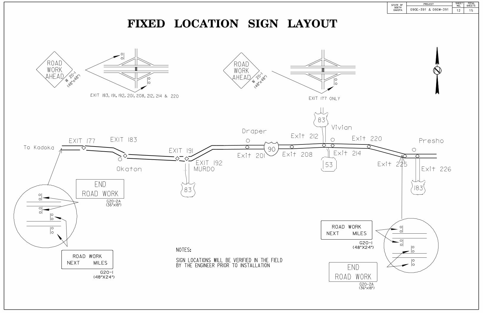
TRAFFIC CONTROL Full depth concrete repairs shall be confined to a single lane width, leaving the adjoining lane open as a through traffic lane. Traffic shall not be routed onto the bituminous shoulders. Closure of both mainline lanes will not be permitted. It will be permissible to work on both the eastbound and westbound lanes simultaneously. All construction operations shall be conducted in the general direction of traffic movement. The length of repair zones (encompassing more than one repair location) will depend on the Contractor’s operation, however, the length shall not exceed 3 miles and it will be classified and signed as one repair zone by placement of continuous channelization throughout the entire length of the repair zone. Under no circumstances will the Contractor be allowed to set up two work zones in the same direction of travel which are closer than 3 miles apart. The Contractor's vehicles and equipment will not be allowed to use the maintenance crossovers at any time during the construction of the project. Contractor’s vehicles or equipment entering or leaving a closed work area or when traveling in an open lane at speeds less than 40 MPH shall display a flashing amber light. Storage of vehicles and equipment shall be as near the right-of-way as possible. Contractor’s employees should mobilize at a location off the right-of-way and arrive at the work sites in a minimum number of vehicles necessary to perform the work. Indiscriminate driving and parking of vehicles within the right-of-way will not be permitted. Any damage to the vegetation, surfacing, embankment, delineators and existing signs resulting from such indiscriminate use shall be repaired and/or restored by the Contractor, at no expense to the State, and to the satisfaction of the Engineer. Work activities will not be allowed during non-daylight hours. All traffic control sign locations shall be set in the field by the Contractor and verified by the Engineer prior to installation.
TRAFFIC CONTROL (CONTINUED) Fixed location signing placed more than two days prior to the start of construction shall be covered until the time of construction. The cost of materials, labor and equipment necessary to complete this work shall be incidental to other contract items. No separate payment will be made. Removing, relocating, covering, salvaging and resetting of existing traffic control devices, including delineation, shall be the responsibility of the Contractor. Cost for this work shall be incidental to the contract unit prices for the various items unless otherwise specified in the plans. Any delineators and signs damaged or lost shall be replaced by the Contractor at no cost to the State. The Contractor shall provide documentation that all breakaway sign supports comply with FHWA NCHRP 350 crash-worthy requirements. The contractor shall provide post installation details at the preconstruction meeting for all steel post breakaway sign support assemblies. The Contractor shall designate an employee whose primary responsibility is for the maintenance of traffic, 24 hours a day and 7 days a week. The designated person must have sufficient training and experience in the field of construction traffic control and be knowledgeable about the Manual of Uniform Traffic Control Devices (MUTCD). The cost of the traffic control person shall be incidental to the contract lump sum price for TRAFFIC CONTROL, MISCELLANEOUS. The employee selected shall be approved by the Engineer. Name, phone number, and location of person or persons shall be provided to the SD Department of Transportation, SD Highway Patrol, and the respective County Sheriff’s Departments. Traffic will be maintained on the proper directional set of lanes and ramps throughout the project during repair operations. No crossing over of traffic to the opposing set of lanes or wrong way movement on ramps will be allowed. The Contractor will so arrange the details of their operations as to cause a minimum of inconvenience and delay to the traveling public. At interchange ramp tapers, location of signs, barricades and channelizing devices on the mainline shall be adjusted to accommodate traffic entering or leaving the work area.
PROJECT STATE OF
SD 090E-391 & 090W-391
SHEET NO.
2 15
TOTAL SHEETS

TRAFFIC CONTROL (CONTINUED) Certified flaggers will be required in a work zone occupied by workers and or equipment when work activity presents a hazard to the worker or through traffic. The Contractor will be paid for the actual quantity of movable signs and advance warning arrow panels used, not to exceed four repair zones, regardless of the number of times they are moved or the number of work zones. No payment will be made for signs used in traffic set ups exceeding four repair zones. Signs may use a hinged section or tabs to expedite changing the message. If hinged signs or tabs are used, cost of the hinged section and tabs shall be incidental to the contract unit price per unit for Traffic Control and shall be considered as one sign for payment purposes. The Contractor shall place an eight foot Type III Barricade in front of each repair area prior to the removal of the concrete repair section. The Contractor will be paid for twelve Type III Barricades, providing at least twelve are in use at the same time. If the Contractor chooses to remove more than twelve repair sections at any one time, The Contractor at no expense to the State, shall furnish additional barricades. Signs shall be removed, covered or turned from view and channelizing devices removed when no longer applicable. Resetting, temporary relocation and/or covering of existing traffic control devices as necessary to adequately maintain traffic or perform the work shall be the responsibility of the contractor and the cost shall be incidental to the contract lump sum price for Traffic Control, Miscellaneous. The Contractor is responsible to ensure that all traffic control devices are displayed in accordance with the MUTCD, corresponding plan sheets and standard plates illustrated in the plans. If a device is improperly displayed, or not displayed at all when it should be, it will be considered as an infraction upon the plans. Channelizing drums are to be of a two part type construction with breakaway bases. All individual drum locations shall be adequately marked on the roadway surface to expedite their replacement upon the event that any drums become displaced. The cost of these devices shall be incidental to the contract lump sum price for “Traffic Control Miscellaneous”.
TRAFFIC CONTROL (CONTINUED) The Contractor may use 42" Grabber Cones for longitudinal delineation only. All tapers, lane transitions, and marking of full depth repairs shall be accomplished utilizing drums in accordance with the MUTCD. All traffic control devices are to be in like new condition. Any traffic control device that warrants replacement due to its poor condition or absence shall be replaced immediately by the Contractor at his expense. CONTINUOUSLY REINFORCED PCC PAVEMENT REPAIR – EAST OF MRM 210 The Engineer will mark the location of the area to be repaired on construction. The Contractor shall saw the in place concrete transversely at four locations for each repair area. Two saw cuts shall be full depth. The other two saw cuts shall be partial depth saw cuts and shall be made to a depth just above the in place reinforcing steel, and be placed 4’ outside of the previous full depth saw cuts. The Contractor shall lift out or break out the center section (including reinforcing steel) and then use hand held jackhammers (not exceeding 45 pounds) to remove the remaining 4’ of concrete at each end of the repair area, leaving the reinforcing steel in place. Hand held jackhammers (not exceeding 15 pounds) shall be used to remove the last 1’ of concrete leading up to the partial depth saw cut. Care shall be taken not to cut, bend or otherwise damage the in place reinforcing steel. Damage to in place reinforcing steel or to in place concrete beyond the repair area will be replaced at the Contractor’s expense, to the satisfaction of the Engineer. The Contractor shall remove and dispose of the in place concrete and shape and recompact the underlying base material prior to placement of concrete. Existing exposed reinforcing steel and concrete faces shall be cleaned by sandblasting and compressed air to remove dirt and debris prior to placement of concrete.
CONTINUOUSLY REINFORCED PCC PAVEMENT REPAIR – EAST OF MRM 210 (CONTINUED) Place reinforcing steel according to the notes and layout for 26’ Continuously Reinforced PCC Pavement Repair Area East of MRM 210. No. 4 transverse deformed steel bars 30” center to center 5’ long shall be placed in drilled holes. A drilled hole shall be placed six inches from the full depth transverse saw cut on both ends of the repair area. No.4 deformed steel bars shall be placed across the width of the repair area and lapped 4’ minimum with the drilled in bars. The drilled holes and rebar shall be installed per the steel bar installation note. Repair areas 8’ or less in length shall have partial depth saw cuts made at the repair limits. The existing concrete between these saw cuts shall be removed using hand held jackhammers as previously noted. The existing reinforcing steel will remain in place as previously noted. No additional reinforcement will be placed in these smaller repair areas where all existing reinforcement remains. CONTINUOUSLY REINFORCED PCC PAVEMENT REPAIR – WEST OF MRM 210 The Engineer will mark the location of the area to be repaired on construction. The Contractor shall saw the in place concrete transversely full depth at the limits of the repair area. The Contractor shall lift out or break out the center section of concrete (including reinforcing steel). The Contractor shall remove and dispose of the in place concrete and shape and recompact the underlying base material prior to placement of concrete. Existing concrete faces shall be cleaned by sandblasting and compressed air to remove dirt and debris prior to placement of concrete. Place reinforcing steel according to the notes and layout for 24’ Continuously Reinforced PCC Pavement Repair Area West of MRM 210.
PROJECT STATE OF SOUTH DAKOTA 090E-391 & 090W-391
SHEET NO.
3 15
TOTAL SHEETS

CONTINUOUSLY REINFORCED PCC PAVEMENT REPAIR – WEST OF MRM 210 (CONTINUED) No. 5 transverse deformed steel bars 30” center to center 5’ long shall be placed in drilled holes. A drilled hole shall be placed six inches from the full depth transverse saw cut on both ends of the repair area. No.5 deformed steel bars shall be placed across the width of the repair area and lapped 4’ minimum with the drilled in bars. The drilled holes and rebar shall be installed per the steel bar installation note. CONTINUOUSLY REINFORCED PCC PAVEMENT REPAIR – GENERAL Concrete placed adjacent to asphalt concrete shoulders shall be formed full depth to match the width of existing concrete pavement. Care shall be taken to limit the amount of shoulder damaged during concrete removal and form placement. The excavated area of the asphalt concrete shoulder adjacent to repair areas shall be filled with asphalt concrete cold millings furnished by the State and located in the Murdo Maintenance Yard. Payment for loading, hauling and any incidentals required for placing the cold millings shall be incidental to the contract unit price per square yard for “Continuously Reinforced PCC Pavement Repair”. A central stationary plant site or truck mixers, or self contained, mobile, continuous mixers, meeting the requirements of Section 460.3D or 460.3E, shall be used for all concrete repair work unless otherwise approved by the Engineer. Either delivery method must ensure that all requirements pertaining to delivery and placement of the concrete as noted in the Standard Specifications Section 380.3.G and 380.3.H are met. To allow the adjacent concrete to reach its maximum expansion, concrete shall not be placed in the repair areas before 12:00 (noon) or as directed by the Engineer. Any saw cuts that extend beyond the boundaries of the repair area will be filled with a non-shrinkage mortar mix at the Contractor’s own expense.
CONTINUOUSLY REINFORCED PCC PAVEMENT REPAIR – GENERAL (CONTINUED) Upon placement of the concrete, all repair areas will be straight edged to ensure a smooth riding surface and shall be textured transversely with the pavement by finishing with a stiff broom. Repair areas longer than ten (10) feet shall be checked with a ten (10) foot straight edge. The permissible longitudinal and transverse surface deviation shall be 1/8 inch in 10 feet. New pavement thickness shall be equal to existing pavement thickness (10” East of MRM 210 and 8” West of MRM 210). Concrete shall meet the requirements of the Standard Specifications Section 380, except as modified by the following notes: The slump requirement will be limited to three (3”) inches maximum after water reducer is added and the concrete shall contain 4.5% to 7.0% entrained air content. Coarse aggregate shall be crushed ledge rock, Size No. 1 unless an alternate gradation is approved by the concrete engineer as part of the mix design submittal. The Contractor is responsible for the mix design used. The Contractor shall submit a mix design and supporting documentation for approval at least 2 weeks prior to use. In lieu of submitting a mix design, the Contractor may elect to use one of the following dependent upon the type of cement to be used: LB / CU YD LB / CU YD Cement 800 (Type I-II) 710 (Type III) Water 282 300 Fine Aggregate 1039 1114 Coarse Aggregate 1726 1668 The use of a water reducer at manufacturer’s recommended dosage will be required. Concrete shall be cured for a minimum of 48 hours before opening to traffic. The 48 hours is based upon a concrete surface temperature of 60 degrees Fahrenheit or higher throughout the cure period. If the concrete temperature falls below 60 degrees Fahrenheit, the cure time shall be extended or other measures shall be taken, at no additional cost to the State, to ensure that strength of 4000 psi is attained prior to opening repair to traffic.
CONTINUOUSLY REINFORCED PCC PAVEMENT REPAIR – GENERAL (CONTINUED) Concrete shall be covered with a suitable insulation blanket consisting of closed cell polystyrene foam protected by at least one layer of plastic. Insulation blanket shall have and R-value of at least 0.5, as rated by the manufacturer. Insulation blanket shall be left in place, except for joint sawing operations. Insulation blanket shall be overlapped on the existing concrete by 4’. Locations and quantities of Continuously Reinforced PCC Pavement Repair are subject to change in the field at the discretion of the Engineer. Continuously Reinforced Pavement Repair will be measured to the nearest tenth of a foot and computed to the nearest tenth of a square yard. Continuously Reinforced Pavement Repair, measured as provided above, will be paid for at the contract unit price per square yard. This will be full compensation for all labor, equipment, materials, and incidentals necessary for the saw cutting, removing of material, preparation of removed area, furnishing and placing concrete, finishing and curing of Continuously Reinforced Pavement Repair. RESTORATION OF GRAVEL CUSHION After removal of full depth concrete pavement, an inspection of the gravel cushion subgrade is to be made. Areas of excess moisture are to be dried to the satisfaction of the Engineer. Loose material shall be removed and disturbed areas leveled and compacted to the satisfaction of the Engineer. If additional gravel cushion material is required, the Contractor shall furnish, place and compact gravel cushion to the satisfaction of the Engineer. Gravel Cushion material shall be approved by the Engineer and shall be furnished by the Contractor. Gravel Cushion material shall conform to Section 882. Cost of this work, including gravel cushion material, shall be incidental to the contract unit price bid per square yard for “Continuously Reinforced PCC Pavement Repair”.
PROJECT STATE OF SOUTH DAKOTA 090E-391 & 090W-391
SHEET NO.
4 15
TOTAL SHEETS

RESTORATION OF ASPHALT CONCRETE BOND BREAKER After removal of full depth concrete pavement, an inspection of the asphalt concrete bond breaker is to be made. Loosed material shall be removed and disturbed areas leveled and compacted to the satisfaction of the Engineer. Asphalt concrete cold millings shall be used to replace any damaged areas. Cost for this work, including asphalt concrete cold millings, shall be incidental to the contract unit bid price per square yard for “Continuously Reinforced PCC Pavement Repair”. PLACEMENT OF REINFORCING STEEL FOR CONTINUOUSLY REINFORCED PCC PAVEMENT REPAIR – EAST OF MRM 210 After removal of the in place concrete and repair of the gravel cushion subgrade, new reinforcing steel shall be installed according to plan details. Refer to the Pavement Repair Area details.
1. New No. 6 longitudinal bars shall be lap spliced with the preserved in place longitudinal bars.
2. Additional No. 6 longitudinal bars shall be centered between
every other set of two spliced longitudinal bars throughout the width of the repair area. The additional longitudinal bars shall overlap into the existing concrete 9” on both sides of the repair area. Drilled holes will be required and the additional longitudinal bars shall be inserted in accordance with the notes for Steel Bar Insertion. The additional longitudinal bars shall then be lap spliced with No. 6 longitudinal bars across the length of the repair area.
3. No. 4 transverse bars shall be drilled in starting 6” from both
ends of the repair area. The spacing shall then be 30” center to center throughout the length of the repair area. The transverse bars shall overlap 9” into the existing concrete. New No. 4 deformed steel bars shall be placed across the width of the repair area and lapped 4’ minimum with the drilled in bars. The drilled holes and rebar shall be installed per the steel bar installation note.
Cost for the reinforcing steel, ties, labor and equipment shall be incidental to the contract unit price per square yard for “Continuously Reinforced PCC Pavement Repair”.
PLACEMENT OF REINFORCING STEEL FOR CONTINUOUSLY REINFORCED PCC PAVEMENT REPAIR – WEST OF MRM 210 After removal of the in place concrete and repair of the gravel cushion subgrade, new reinforcing steel shall be installed according to plan details. Refer to the Pavement Repair Area details.
1. No. 5 longitudinal bars shall be drilled in between every in
place longitudinal steel bar. The No. 5 longitudinal bars shall overlap into the existing concrete 9” on both sides of the repair area. Drilled holes will be required and the additional longitudinal bars shall be inserted in accordance with the notes for Steel Bar Insertion. The additional longitudinal bars shall then be lap spliced with new No. 5 longitudinal bars across the length of the repair area.
2. No. 5 transverse bars shall be drilled in starting 6” from both
ends of the repair area. The spacing shall then be 30” center to center throughout the length of the repair area. The transverse bars shall overlap 9” into the existing concrete. New No. 5 deformed steel bars shall be placed across the width of the repair area and lapped 4’ minimum with the drilled in bars. The drilled holes and rebar shall be installed per the steel bar installation note.
Cost for the reinforcing steel, ties, labor and equipment shall be incidental to the contract unit price per square yard for “Continuously Reinforced PCC Pavement Repair”. CONCRETE PLACEMENT AND FINISHING FOR CONTINUOUSLY REINFORCED PCC PAVEMENT REPAIR Concrete placement and finishing shall conform to Section 380. Finishing and curing will not be measured for payment and cost of this work and materials shall be incidental to the contract unit price bid per square yard for “Continuously Reinforced PCC Pavement Repair”.
STEEL BAR INSERTION The Contractor shall insert steel bars into drilled holes in the joints as specified. An epoxy resin adhesive must be used to anchor the steel bar into the drilled hole. The steel bars shall be cut to the specified length by sawing and shall be free from burring or other deformations. Shearing will not be permitted. Epoxy resin adhesive shall be of the type intended for horizontal applications, and shall conform to the requirements of ASTM C 881, Type IV, Grade 3 (equivalent to AASHTO M235, Type IV, Grade 3) The diameter of the drilled holes in the existing concrete for the steel bars shall not be less than 1/8 inch nor more than 3/8 inch greater than the overall diameter of the steel bar. Holes drilled into the existing concrete pavement shall be located at mid-depth of the slab and true and normal. The drilled holes shall be blown out with compressed air using a device that will reach to the back of the hole to ensure that all debris or loose material has been removed prior to epoxy injection. A rigid frame or mechanical device will be required to guide the drill to ensure proper horizontal and vertical alignment of the steel bars in the drilled holes. Mix the epoxy resin as recommended by the manufacturer and apply by an injection method approved by the Engineer. If an epoxy pump is utilized, it shall be capable of metering the components at the manufacturer’s designated rate and be equipped with and automatic shut-off. The pump shall shut off when any of the components are not being metered at the designated rate. Fill the drilled holes one-third to one-half full of epoxy, or as recommended by the manufacturer, prior to insertion of the steel bar. Care shall be taken to prevent epoxy from running out of the horizontal holes prior to steel bar insertion. Rotate the steel bar during insertion to eliminated voids and ensure complete bonding of the bar. Insertion of the bars by the dipping method will not be allowed.
PROJECT STATE OF SOUTH DAKOTA 090E-391 & 090W-391
SHEET NO.
5 15
TOTAL SHEETS

STEEL BAR INSERTION (CONTINUED) Cost for the steel bars shall be incidental to the contract unit price per square yard for “Continuously Reinforced PCC Repair”. Cost for the epoxy resin adhesive, drilling of holes, applying the adhesive, inserting the steel bars into the drilled holes and all other items incidental to the insertion of the steel bars shall be incidental to the contract unit price per each for “Insert Steel Bar in PCC Pavement”. SAW AND SEAL JOINTS All longitudinal and transverse joints at concrete repair areas shall be sawed and sealed. Joints shall not be sealed unless they are thoroughly clean and dry. Cleaning shall be accomplished by sand blasting and other tools as necessary. Just prior to sealing, each joint shall be blown out using a jet of compressed air to remove all trace of dust. All joints shall be sealed with Hot Pour joint sealant. Cost for sawing and sealing of the longitudinal construction joints and transverse joints shall be incidental to the contract unit price per square yard for “Continuously Reinforced PCC Pavement Repair”. TABLE OF PROJECT QUANTITIES (For Information Only) BID ITEM 090E-391 090W-391 Mobilization LS LS Remove Concrete Pavement( SqYd) 137.5 133.4 Continuously Reinforced PCC 137.5 133.4 Pavement Repair (SqYd) Insert Steel Bar in PCC Pavement (Each) 334 300 Flagging (Hour) 10 10 Traffic Control (Unit) 1479 1479 Traffic Control, Miscellaneous LS LS Type C Advance Warning Arrow 2 2 Panel (Each)
GENERAL NOTES FOR CONTINUOUSLY REINFORCED PCC PAVEMENT REPAIR (CONTINUED) TABLE OF CONTINUOUSLY REINFORCED PCC PAVEMENT REPAIR
LOCATION
LANE
LENGTH
FEET
WIDTH
FEET
SQYDS EASTBOUND LANES
175.70 DL 10 4 4.4 181.55 DL 12 4 5.3 181.55 PL 12 4 5.3 183.32 DL 12 8 10.7 183.32 PL 12 4 5.3 192.79 DL 12 4 5.3 192.79 DL 12 4 5.3 198.06 DL 16 12 21.3 198.06 PL 16 12 21.3 213.45 DL 12 8 10.7 221.76 DL 8 8 7.1 221.78 DL 8 8 7.1 221.87 DL 8 8 7.1 221.88 DL 8 8 7.1 221.93 DL 8 8 7.1 221.94 DL 8 8 7.1 WESTBOUND LANES
177.86 DL 20 12 26.7 178.02 DL 8 4 3.6 178.02 DL 4 4 1.8 185.18 DL 12 4 5.3 185.18 DL 12 4 5.3 185.18 DL 4 4 1.8 185.75 DL 12 8 10.7 185.75 PL 12 8 10.7 198.06 DL 16 12 21.3 198.06 PL 16 12 21.3 211.59 DL 8 8 7.1 212.07 PL 12 8 10.7 224.71 DL 8 8 7.1 Total 270.9
PROJECT STATE OF SOUTH DAKOTA 090E-391 & 090W-391
SHEET NO.
6 15
TOTAL SHEETS

HISTORICAL PRESERVATION OFFICE CLEARANCES To obtain State Historical Preservation Office (SHPO) clearance, a cultural resources survey may need to be conducted by a qualified archaeologist. In lieu of a cultural resources survey, the Contractor could request a records search from Jim Donohue, State Archaeological Research Center (SARC). Provide SARC with the following: a topographical map or aerial view on which the site is clearly outlined, site dimensions, project number, and PCN. If applicable, provide evidence that the site has been previously disturbed by farming, mining, or construction activities with a landowner statement that no artifacts have been found on the site. The Contractor shall arrange and pay for the cultural resource survey and/or records search. If any earth disturbing activities occur within the current geographical or historic boundaries of any South Dakota reservation, the Contractor shall obtain Tribal Historical Preservation Office (THPO) clearance. If no THPO exists, the required SHPO clearance shall suffice, with documentation of Tribal contact efforts provided to SHPO. To facilitate SHPO or THPO responses, the Contractor should submit a records search or cultural resources survey report to Tom Lehmkuhl, DOT Environmental Engineer, 700 East Broadway Avenue, Pierre, SD 57501-2586 (605-773-3180). Allow 30 days from the date this information is submitted to the Environmental Engineer for SHPO/THPO approval. The Contractor is responsible for obtaining all required permits and clearances for staging areas, borrow sites, waste disposal sites, and all material processing sites. The Contractor shall provide the required permits and clearances to the Engineer at the preconstruction meeting. WASTE DISPOSAL SITE The Contractor will be required to furnish a site(s) for the disposal of construction/demolition debris generated by this project. Construction/demolition debris may not be disposed of within the State ROW.
WASTE DISPOSAL SITE (CONTINUED) The waste disposal site(s) shall be managed and reclaimed in accordance with the following from the Administrative Rules of South Dakota (Solid Waste) Article 74:27 administered by the Department of Environment and Natural Resources. The waste disposal site(s) shall not be located in a wetland, within 200 feet of surface water, or in an area that adversely affects wildlife, recreation, aesthetic value of an area, or any threatened or endangered species, as approved by the Engineer. If the waste disposal site(s) is located such that it is within view of any ROW, the following additional requirements shall apply: 1. Construction/demolition debris consisting of concrete,
asphalt concrete, or other similar materials shall be buried in a trench completely separate from wood debris. The final cover over the construction/demolition debris shall consist of a minimum of 1 foot of soil capable of supporting vegetation. Waste disposal sites provided outside of the State ROW shall be seeded in accordance with Natural Resources Conservation Service recommendations. The seeding recommendations may be obtained through the appropriate County NRCS Office. The Contractor shall control the access to waste disposal sites not within the State ROW through the use of fences, gates, and placement of a sign or signs at the entrance to the site stating “No Dumping Allowed”.
2. Concrete and asphalt concrete debris may be stockpiled
within view of the ROW for a period of time not to exceed the duration of the project. Prior to project completion, the waste shall be removed from view of the ROW or buried and the waste disposal site reclaimed as noted above.
The above requirements will not apply to waste disposal sites that are covered by an individual solid waste permit as specified in SDCL 34A-6-58, SDCL 34A-6-1.13, and ARSD 74:27:10:06. Failure to comply with the requirements stated above may result in civil penalties in accordance with South Dakota Solid Waste Law, SDCL 34A-6-1.31.
WASTE DISPOSAL SITE (CONTINUED) All costs associated with furnishing waste disposal site(s), disposing of waste, maintaining control of access (fence, gates, and signs), and reclamation of the waste disposal site(s) shall be incidental to the various contract items.
PROJECT STATE OF SOUTH
DAKOTA 090E-391 & 090W-391
SHEET NO.
7 15
TOTAL SHEETS


ITEMIZED LIST FOR TRAFFIC CONTROL
SIGN CODE SIGN SIZE DESCRIPTION NUMBER
REQUIREDUNITS PER
SIGN UNITS
G20-1 48'' x 24'' ROAD WORK NEXT ## MILES 4 24 96G20-2A 36'' x 18'' END ROAD WORK 4 17 68
R2-1 30'' x 36'' SPEED LIMIT ## 16 23 368W3-5 48'' x 48'' SPEED REDUCTION 8 34 272W4-2 48'' x 48'' LEFT OR RIGHT LANE ENDS (SYMBOL) 8 34 272
W20-1 48'' x 48'' ROAD WORK #### FT. OR AHEAD 25 34 850W20-5 48'' x 48'' LT. OR RT. LANE CLOSED #### FT. OR AHEAD 8 34 272W20-7a 48'' x 48'' FLAGGER 4 34 136
SPECIAL 30'' x 24'' FINES DOUBLED 8 18 144***** ***** TYPE III BARRICADE - 8 FT. SINGLE SIDED 12 40 480
TOTAL UNITS 2958
PROJECT STATE OF SOUTH
DAKOTA 090E-391 & 090W-391
SHEET NO.
13 15
TOTAL SHEETS

