progress in helicopter infrared signature suppression · pdf fileprogress in helicopter...
TRANSCRIPT

Chinese Journal of Aeronautics, (2014),27(2): 189–199
Chinese Society of Aeronautics and Astronautics& Beihang University
Chinese Journal of Aeronautics
Progress in helicopter infrared signature suppression
Zhang Jingzhou *, Pan Chengxiong, Shan Yong
Jiangsu Province Key Laboratory of Aerospace Power System, College of Energy & Power Engineering, Nanjing Universityof Aeronautics and Astronautics, Nanjing 210016, China
Received 24 April 2013; revised 4 November 2013; accepted 10 December 2013Available online 19 February 2014
*
E
Pe
10
ht
KEYWORDS
Helicopter;
Infrared radiation;
Infrared suppression;
Internal aerodynamics;
Mixer-ejector
Corresponding author. Tel.
-mail address: zhangjz@nua
er review under responsibilit
Production an
00-9361 ª 2014 Production
tp://dx.doi.org/10.1016/j.cja.2
: +86 25
a.edu.cn
y of Edit
d hostin
and hosti
014.02.0
Abstract Due to their low-attitude and relatively low-speed fight profiles, helicopters are subjected
to serious threats from radio, infrared (IR), visual, and aural detection and tracking. Among these
threats, infrared detection and tracking are regarded as more crucial for the survivability of helicop-
ters. In order to meet the requirements of infrared stealth, several different types of infrared sup-
pressor (IRS) for helicopters have been developed. This paper reviews contemporary
developments in this discipline, with particular emphasis on infrared signature suppression,
advances in mixer-ejectors and prediction for helicopters. In addition, several remaining challenges,
such as advanced IRS, emissivity optimization technique, helicopter infrared characterization, etc.,
are proposed, as an initial guide and stimulation for future research. In the future, the comprehen-
sive infrared suppression in the 3–5 lm and 8–14 lm bands will doubtfully become the emphasis of
helicopter stealth. Multidisciplinary optimization of a complete infrared suppression system
deserves further investigation.ª 2014 Production and hosting by Elsevier Ltd. on behalf of CSAA & BUAA.
Open access under CC BY-NC-ND license.1. Introduction
Helicopters play important roles in air-to-ground fire coveringand short-distance air-to-air fights, as well as battlefield forcetransferring and anti-tank missions. Due to their low-attitudeand relatively low-speed fight profiles, helicopters are subjected
to serious threats from radio, infrared (IR), visual, and auraldetection and tracking. Among these threats, infrared detec-tion and tracking are regarded as more crucial for the surviv-
ability of helicopters. Firstly, passive detection and tracking by
84895909.
(J. Zhang).
orial Committee of CJA.
g by Elsevier
ng by Elsevier Ltd. on behalf of C
07
infrared signature seeking missiles are tactically superior to ac-tive ones for a comparable detection range. Infrared seekers
have exploited techniques to passively acquire and interceptairborne targets by detecting their infrared emitting energy.Developments in infrared detection and tracking have in-
creased the effectiveness of infrared-guided missiles, whichare now portable and have proliferated world-wide. The rapidadvances in processor and detector array technology have led
to enhanced sensitivity, low noise, multi-spectral, and smartdetection capabilities.1–3 On the other hand, with the increaseof the ratio of power to weight for turbo-shaft engines mainlyequipped in helicopters, the exhaust temperature increases tre-
mendously, resulting in an infrared signature augment inten-sively. Consequently, infrared signature suppression is animportant issue associated with helicopter susceptibility.
This paper reviews contemporary developments in this dis-cipline, with particular emphasis on infrared signaturesuppression and prediction from helicopters. In addition,
SAA & BUAA. Open access under CC BY-NC-ND license.

Fig. 2 Infrared signature variation of a Bell UH-1H helicopter.5
190 J. Zhang et al.
several remaining challenges are proposed, as an initial guideand stimulation for further research.
2. Sources of infrared signature
The sources of infrared signature in a helicopter and their clas-sification are shown in Fig. 1. The important internal infrared
sources include plume emission and surface emissions from thefollowing: (a) engine hot parts, (b) exhaust plume, and (c) air-frame skin heated by the engine and plume. Besides, the re-
flected skyshine, earthshine, and sunshine contribute to thetotal infrared signature.
The attenuation of infrared radiation in the atmosphere is
highly dependent on wavelength of radiation, temperature,and composition of radiation participating gases. Mainly twoatmospheric windows (3–5 lm and 8–14 lm) are used for sur-
veillance and tracking where the transmittance is high. Tailpipeis the major and reliable source for infrared signature level inthe 3–5 lm band because of the large amount of heat producedby combustion inside the gas turbine engine. The helicopter
rear fuselage skin is always heated by the flow of hot combus-tion products in the embedded engine. Though the spectralradiance of the rear fuselage is less than that of the tailpipe,
infrared emission from the rear fuselage is important especiallyin the 8–14 lm band. Meanwhile, the solid angle subtended bythe rear fuselage skin is an order of magnitude larger than that
of the tailpipe. Unlike surfaces of solids, gases emit and absorbradiation only at discrete wavelengths associated with specificrotational and vibrational frequencies. These frequencies de-pend on the particular type of molecules, temperature, pres-
sure, and molecular concentration of radiation participatingspecies. In general, the infrared signature level from the plumeis much less significant than those from the tailpipe and the rear
fuselage skin, especially in the 8–14 lm band.4
Thompson et al.5 presented the infrared signature break-down of a Bell-205 (UH-1H) helicopter in the 3–5 lm band,
as shown in Fig. 2. The signature values shown in this figurewere predicted using the infrared signature modeling softwaredeveloped by DAVIS. The largest contributor to the helicopter
infrared signature is the direct view of the 600–700 �C powerturbine stages. The next signature component of importanceis the hot tailpipe metal. Visible up to 120� off-tail, the tailpipemetal provides a strong target for infrared-guided missiles for
all views from behind the helicopter. It is also shown that the
Fig. 1 Sources of infrared signature in a helicopter and their
classification.
engine exhaust plume is the least contributor, followed by the
tail boom heated by the plume. When viewed from the frontand sides, the plume and the airframe contribute, and whenviewed from the rear, the engine hot parts become the major
source of infrared radiation.
3. Advances in infrared suppressors
The first generation of infrared suppressors (IRSs) for helicop-ters typically features an upward-bend nozzle shielded from adirect view by an insulating cowl. It is generally regarded as
being adapted for opposing infrared-guided missiles workingat the 1.7–2.8 lm band. While this principle holds for radiationof any wavelength, new warheads operating in the 3–5 lm bandhave the additional capability of locking on weaker signals
emitted at relatively lower temperatures. The exhaust plumeradiates a detectable amount of energy due to discrete rays inthe carbon dioxide spectrum in the 3–5 lm band. Diluting the
engine plume with cold ambient air decreases CO2 concentra-tion and temperature and therefore reduces the target detect-ability. This is most conveniently achieved by means of a
passive ejector as has been widely recognized. When the pri-mary jet mixes out to fill the larger area cross-section of themixing duct, the turbulent shear layer entrains a secondary flowinto the mixing duct to dilute the primary flow. Based on this
mechanism, several different types of IRS for helicopter engineshave been developed, such as cascaded ejector-based IRS, blackhole ocarina (BHO) IRS, lobed mixer-ejector IRS, etc.6–8
3.1. BHO IRS
The BHO system used on the YAH-64 Apache helicopter is a
low-cost IR suppressor6 without any moving part, as seen inFig. 3. In Fig. 3, h denotes the azimuthal angle, R1 is relativeinfrared intensity. Known as the ‘‘black hole’’ infrared sup-
pression system, the principle revolves around directing the en-gine exhaust through special ducts which combine the effluxwith the air-stream passing over the aircraft. The air-streamthus dissipates the hot exhaust that emerges from the vents
evenly, rather than allowing hot spots to appear. Prior to exit,the temperature is further reduced from 574 �C to 304 �C. Theengine exhaust ports are angled outward from the airframe to
better direct the output into the air-stream. Secondary vents

Fig. 3 BHO suppressor.6
Fig. 4 Infrared suppression system.9
Fig. 5 Infrared suppression system used in SA365C.7
Progress in helicopter infrared signature suppression 191
along the upper surface of the outlets help to dissipate the heat
by diverting part of the emissions into the flow along the top ofthe airframe. To further reduce the infrared signature of theaircraft, exhaust output is used to draw in fresh air in orderto cool both the engines and the transmission, the latter’s cool-
ing being assisted through oil heat exchangers.Bettini et al.9 conducted analysis of the fluid-dynamic per-
formance of a complete IRS system for a helicopter engine,
assuming the coupling of the infrared suppression system tothe Rolls-Royce MK 1004 turbo-shaft engine that equips theMangusta A129 light-attack helicopter. An important effect
introduced by the infrared suppression configuration is themixing of the hot exhaust gases with fresh ambient air. Theexternal surface of the masking box has a high porosity that
allows the suction of external air into the suppression systemusing the ejector effect of the high-speed internal mainstreamof the hot gases. The porosity of the masking box’s externalsurface is obtained by a high number of louvers (more than
18000) as sketched in Fig. 4. Each louver has an open airheight of only 0.5 mm.
3.2. Lobed mixer-ejector IRS
Fig. 5 shows the lobed mixer-ejector IRS adopted by Turbom-eca Dauphin SA365C.7 In Fig. 5, h denotes the azimuthal an-
gle, R1 is relative infrared intensity. Evaluation tests showedthat this kind of infrared suppressors was of high dilution,low turbine backpressure, low aerodynamic drag, compact-ness, and light weight. It reduced infrared signal/noise ratio
in the 3–5 lm band by 39 dB, with an acceptable power losslimited in 2.5% at hover IGE power.
Zhang et al.10–14 made a series of fundamental studies on alobed nozzle mixer-ejector IRS for helicopter exhaust systems.Fig. 6 presents the relationship between infrared intensity and
azimuthal angle for the lobed mixer-ejector IRS. A compre-hensive summary on the lobed nozzle mixer-ejector infraredsignature suppressor was made by Zhang et al.12 The effectsof ambient air pumping-mixing and heat shelter-insulation

Fig. 6 Relative infrared intensity vs azimuthal angle.12
Fig. 7 Comanche IRS.17
192 J. Zhang et al.
on decreasing the target infrared signature and the infrared
signature similarity between two scaled models with differentscale factors were concluded: (a) ambient air pumping-mixingplays a dual role for reducing both the exhaust and mixing
duct temperatures and this role is more obvious in the caseof a larger mass flow ratio of secondary flow to primary flow.Sheltering from the hot mixing duct wall makes the sheltering
sheath temperature close to ambient temperature in case of thesheltering distance greater than 20 mm; (b) ambient airpumping-mixing contributes about 85% suppression for the
total target infrared radiation intensity and heat shelter-insulation contributes about 10% suppression; (c) while theprimary flow velocity, temperature, and pressure are the samefor different scaled models, the irradiances for different scaled
models are almost the same and the infrared radiationintensity is almost proportional to the square of the modelscale factor.
3.3. IRS embed inside helicopter rear airframe
Boeing-Sikorsky RAH-66 Comanche is the first helicopter
developed specifically for a low-observable stealth role.15,16
To reduce the radar cross-section, the all-composite fuselagesides are flat and canted, and rounded surfaces are avoidedby use of faceted turret and engine covers. It is reported that
the Comanche will be able to approach five times closer toan enemy’s radar than a YAH-64 Apache helicopter withoutbeing detected. The advanced rotor design permits operation
at low speed, allowing the Comanche to sneak 40% closer toa target than the Apache, without being detected by an acous-tical system. The Comanche is the first helicopter in which the
infrared suppression system is integrated into the airframe, asseen in Fig. 7. This innovative Sikorsky design feature providesIRSs that are built into the tail-boom, providing ample length
for complete and efficient mixing of engine exhaust and cool-ing air flowing through inlets above the tail. The mixed exhaustis discharged through slots built into an inverted shelf on thesides of the tail-boom. The gases are cooled so thoroughly that
a heat-seeking missile cannot find and lock on the Comanche.The Comanche only radiates 25% of the engine heat of currenthelicopters.
Utilizing a ground test model, an experimental diagnosticstudy on the infrared suppressor integrating the exhaust sys-tem with the tail part of a helicopter has been performed by
Tang et al.17,18 to investigate the effects of ambient air pump-
ing-mixing and rotor downwash on reducing the exhaust sys-tem temperature and diminishing the target infraredsignature. The result shows that the gas temperature can be re-
duced by at least 50% by a lobed nozzle which injects ambientair to mix with the hot gas; and rotor downwash flow thatcools the tail part of the model can cause a decrease of total
infrared radiation between 3–5 lm and 8–14 lm equivalentto about 39% and 33%.
4. Advances in mixer-ejectors
Passive mixer-ejector is the key element in an infrared suppres-sor for helicopters. In short efficient mixer-ejector systems, theprimary nozzle plays an important role on pumping and mix-
ing capacities. A lobed nozzle is illustrated to be one of the bestchoices for the primary nozzle.19,20
4.1. Mechanism of mixing enhancement
The concept of the lobed nozzle is oriented from the lobed orforced mixer which is firstly used in a turbofan engine to mix
bypass flow and core flow in a short distance. Early researchby Paterson,21 Povinelli and Anderson22 indicated that large-scale secondary flows, not viscous diffusion, were the key to
low-loss efficient mixing. The forced lobes used the thirddimension to initiate large-scale streamwise vortices which stir-red co-flowing streams of fluid together providing convectivemixing rather than shear mixing. The streamwise vortices were
reported to interact within a small distance downstream fromthe mixer trailing edge, but remain the largest-scale flow struc-ture for three to ten lobe wavelengths downstream. Further
investigations on the fundamental mechanism of mixingenhancement were carried out either experimentally or numer-ically by a lot of researchers.23–26 The fundamental features of
the flow development downstream from a lobed mixer were ex-plained by McCormick and Bennett24 and shown schemati-cally in Fig. 8. Small-scale periodic vortex structures, known
as the normal vortices, are generated in the strong free shearlayer shedding from the trailing edge of the lobed mixer, dueto the Kelvin–Helmholtz instability promoted by the inflec-tional velocity profile of the shear layer. These normal vortices

Fig. 8 Schematic of vortical structures downstream from a lobed
mixer.24
Progress in helicopter infrared signature suppression 193
are continuously connected along the perimeter of the convo-luted free shear layer. The contour of these normal vortices is
deformed by the streamwise vortices so that the normal vorti-ces are eventually pinched off and broken down, resulting inhigh levels of turbulent mixing followed by their breakdown
into small-scale turbulent structures. Furthermore, the exis-tence of a counter-rotating streamwise vortex pair within thetroughs of the lobes is also commonly observed downstreamfrom the discharge plane, which are the legs of horseshoe vor-
tices that are developed as the upstream wall boundary layer iswrapped around the lobe peaks.
4.2. Advanced lobed-mixers
The strength of streamwise vortices depends primarily on thelobe geometry. Early preliminary investigations27,28 were
mainly focused on estimating the influences of geometricparameters on the performance of forced exhaust mixersincluding the number of lobes, lobe radial penetration angles,
lobe shape and length, etc. Results from these studies provideda data base for optimizing the design of turbofan forced mixerexhaust systems.
Skebe et al.29 noted that sinusoidally shaped lobes tended
to produce lower secondary flow velocities and mix less effi-ciently than those with a geometry of parallel lobe sidewallsdue to the merger of sidewall boundary layers in the troughs
of the former geometry. Yu et al.30 made velocity and turbu-lence characteristics measurements downstream from a lobedforced mixer with three different trailing edge configurations
using a two-component laser-Doppler anemometer. The threetrailing edge configurations under investigation had the shapesof a square wave, a semi-circular wave, and a triangular wave.Measurements indicated that the strength of the secondary
flow shed by a lobe was not the only parameter which deter-mined the effectiveness of mixing. The boundary layer thick-ness which grew along the side-walls of the lobe penetration
and the subsequent shedding of the boundary layer to the wakeregion were of equal importance.
Recently, some research was conducted for advancement of
the lobed mixer contour, such as scalloping and scarfing of the
lobes, lobe deflection, flow swirling, etc. Yu31 and Mao32 et al.compared scalloped and unscalloped planar mixers with thesame penetration angle and trailing edge profiles. They showed
that the streamwise vorticity was enhanced and its decay rateaccelerated in scalloped mixers, largely because of the forma-tion of two pairs of streamwise vortices at each lobe. They also
reported lower losses for scalloped mixers, compared withother configurations, possibly due to their lowest wetted sur-face area within the penetration region. Salman et al.33 made
a computation for prediction of a non-isothermal three-dimen-sional mixing layer created by a scarfed lobed mixer. Resultsshowed that the scarfed mixer introduced strong flow asymme-tries in the azimuthal direction. This caused adjacent vortical
structures produced by the alternating short and long gulliesof the lobes to interact with one another and this behaviordominated the flow evolution. Nastase and Meslem34 con-
ducted an experiment on vortex dynamics and mass entrain-ment in turbulent lobed jets with and without lobe deflectionangles. Two turbulent 6-lobed air jets with and without lobe
deflection angles were studied experimentally and comparedwith a reference circular jet having the same initial Reynoldsnumber. In the potential core region, the jet with inclined lobes
displayed a superior entrained flow rate reaching up to fourtimes the value of the circular jet while the jet with straightlobes displayed a maximum gain of 70%. The comparison ofthe mean and instantaneous vorticity fields showed that the
lobe inclinations organized the cross flow and amplified itsshear. Lei et al.35 explored the effects of core flow swirl onthe flow characteristics of a scalloped forced mixer. At low
swirl angles, additional streamwise vortices were generatedby the deformation of normal vortices due to the scallopedlobes. With increased core swirl, greater than 10�, additionalstreamwise vortices were generated mainly due to radial velocitydeflection, rather than stretching and deformation of normalvortices. At high swirl angles, stronger streamwise vortices
and rapid interaction between various vortices promoted down-stream mixing. Mixing was enhanced with minimal pressure andthrust losses for inlet swirl angles less than 10�.
4.3. Parameters on mixer-ejector performances
The use of lobed mixers in short efficient systems was firstlypresented by Presz et al.19 They conducted an experimental
study to investigate the benefits of using forced mixer lobesin low-pressure ratio, ejector/diffuser systems. Their resultsshowed over a 100% increase in both pumping and thrust aug-
mentations when compared with conventional ejector designs.The test results also indicated that forced mixer lobes resultedin nearly complete mixing in very short ejector duct lengthsand allowed the use of aggressive diffuser designs without
resulting in stall.Skebe et al.36 made experimental investigations of the ef-
fects of geometric and operating parameter variations, such
as the lobe penetration angel and height, the mixing duct diam-eter and length, the diffuser expand angle, pressure ratio, etc.,on the mixer-ejector pumping performance of a representative
low-pressure ratio jet engine exhaust system. Their results sug-gested guidelines for designing mixer-ejector geometries toachieve optimum pumping efficiency. From the view of jet
momentum utilization, they presented three primary jet spreadregimes, as seen in Fig. 9. For the ‘‘under-utilized’’ condition,
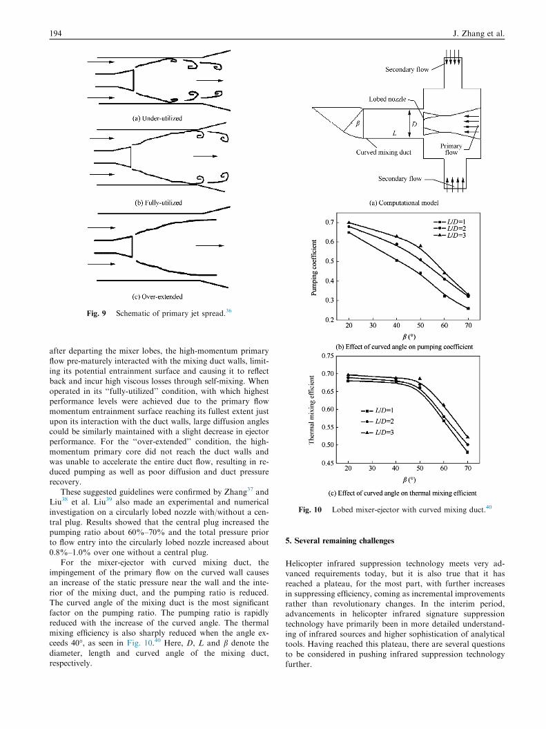
Fig. 9 Schematic of primary jet spread.36
Fig. 10 Lobed mixer-ejector with curved mixing duct.40
194 J. Zhang et al.
after departing the mixer lobes, the high-momentum primary
flow pre-maturely interacted with the mixing duct walls, limit-ing its potential entrainment surface and causing it to reflectback and incur high viscous losses through self-mixing. When
operated in its ‘‘fully-utilized’’ condition, with which highestperformance levels were achieved due to the primary flowmomentum entrainment surface reaching its fullest extent just
upon its interaction with the duct walls, large diffusion anglescould be similarly maintained with a slight decrease in ejectorperformance. For the ‘‘over-extended’’ condition, the high-
momentum primary core did not reach the duct walls andwas unable to accelerate the entire duct flow, resulting in re-duced pumping as well as poor diffusion and duct pressurerecovery.
These suggested guidelines were confirmed by Zhang37 andLiu38 et al. Liu39 also made an experimental and numericalinvestigation on a circularly lobed nozzle with/without a cen-
tral plug. Results showed that the central plug increased thepumping ratio about 60%–70% and the total pressure priorto flow entry into the circularly lobed nozzle increased about
0.8%–1.0% over one without a central plug.For the mixer-ejector with curved mixing duct, the
impingement of the primary flow on the curved wall causesan increase of the static pressure near the wall and the inte-
rior of the mixing duct, and the pumping ratio is reduced.The curved angle of the mixing duct is the most significantfactor on the pumping ratio. The pumping ratio is rapidly
reduced with the increase of the curved angle. The thermalmixing efficiency is also sharply reduced when the angle ex-ceeds 40�, as seen in Fig. 10.40 Here, D, L and b denote the
diameter, length and curved angle of the mixing duct,respectively.
5. Several remaining challenges
Helicopter infrared suppression technology meets very ad-vanced requirements today, but it is also true that it hasreached a plateau, for the most part, with further increases
in suppressing efficiency, coming as incremental improvementsrather than revolutionary changes. In the interim period,advancements in helicopter infrared signature suppression
technology have primarily been in more detailed understand-ing of infrared sources and higher sophistication of analyticaltools. Having reached this plateau, there are several questions
to be considered in pushing infrared suppression technologyfurther.

Fig. 12 Complete STETS suppressor model.42
Progress in helicopter infrared signature suppression 195
5.1. Advanced IR suppressor
In response to the rapid development of infrared detector tech-nology, a generic set of requirements has been assembled todrive advanced IRS designs:
(1) An IRS must provide protection in all the potentialthreat wavebands.
(2) The IRS should not significantly increase the radar
cross-section of the helicopter.(3) The vehicle power loss associated with the combination
of IRS pressure loss, weight, and induced aircraft
drag must not significantly compromise operationaleffectiveness.
(4) The IRS must have reliability levels comparable with the
remainder of the powerplant, with no additional actionrequired outside existing maintenance periods.
(5) The cost of ownership of the system must be low in
order to be compatible with helicopter operations. Inparticular, the non-recurring costs associated with sys-tem development must be minimized.
Ponton and Warnes41 presented an acceptable provision ofcooling flows and management of external aerodynamics. Par-ticularly detailed analysis was carried out for the ‘‘fully inte-
grated’’ Lynx/T800 configuration (see Fig. 11). This IRSinstallation draws plume dilution air from intakes mountedon both the ‘‘rear nacelle’’ and engine bays. Additional pres-
surized cooling flow (from the T800 inlet particle separatorscavenge flow) is used to cool the plug’s center body.
Presz and Werle42 presented a patented suppressor, as seenin Fig. 12, which uses staggered lobes for more complete
Fig. 11 Schematics of the ‘‘fully integrated’’ Lynx/T800 FIRST
IRS installation.41
mixing, a two-stage ejector for higher diffusion rates, an effi-
cient rounded first-stage ejector for engine matching, a turningshroud duct for line of sight blockage, and slanted lobes forfaster mixing (STETS). The first-stage shroud transits from around cross-section to a rectangular one to allow lobe stagger-
ing. Normally such exhaust duct area transition, line of sightblockage, and flow turning would generate significant losseswhich would cause backpressure effects on the jet engine.
The STETS suppressor can dilute the hot jet exhaust, generateline of sight blockage, and provide secondary flow wall coolingwhile decreasing the backpressure on the jet engine.
5.2. Emissivity optimization technique
The rear fuselage skin is heated by the aero-engine embedded
within it. One feasible technique for reducing the infrared sig-nature level from a metallic surface is emissivity reduction oroptimization. The emitted infrared radiation is a function ofrear-fuselage skin temperature and emissivity. Thus, by alter-
ing these two parameters, infrared radiation emitted by a heli-copter can be varied.
For a helicopter on a low-altitude mission, the infrared-
guided threats come from two cases: against a surface-to-airmissile (SAM) and against an air-to-air missile (AAM). Mah-ulikar et al.43 made a preliminary investigation on assessing the
applicability of the rear-fuselage-skin emissivity optimizationtechnique for infrared signatures of low-flying aircraft. The ef-fects of the rear-fuselage skin emissivity on the aircraft lock-on
range (RLO) and the missile infrared irradiance (H) are shownin Fig. 13. In this figure, efuse denotes the rear-fuselage skinemissivity.
It is indicative that optimizing the rear-fuselage skin emis-
sivity reduces the aircraft lock-on range significantly. In the3–5 lm band, the rear-fuselage skin emissivity can be opti-mized to a nonzero value. In the 8–12 lm band, the rear-
fuselage skin emissivity should be reduced to close to zero,for minimizing susceptibility against infrared-guided SAMs.In case of infrared-guided AAMs, there is a non-zero value
of the rear-fuselage skin emissivity for which the infrared

Fig. 13 Effects of rear-fuselage skin emissivity on aircraft lock-
on range and missile infrared irradiance.43
Fig. 14 Plume flow fields (under downwash of 10 m/s).60
196 J. Zhang et al.
signature level from the rear-fuselage skin is minimized.Earthshine reflected by the rear-fuselage skin is significant indictating aircraft susceptibility to infrared-guided SAMs inthe 8–12 lm band, but the role in the 3–5 lm band is insignif-
icant. In the case against a SAM, the lower portion of therear-fuselage skin is visible to the SAM. In the case of anAAM, the side portion of the rear-fuselage skin is visible.
Therefore, different parts of the rear-fuselage skin should havedifferent emissivity, for minimizing its infrared signature levelagainst infrared-guided SAMs and AAMs.
5.3. Characterization in helicopter infrared
All major military research establishments have developed
their own models for prediction of infrared signature level(IRSL) from aircraft. A lot of investigations on predictinginfrared signatures for various infrared targets havebeen made, e.g., exhaust plume44–46, exhaust nozzle47–51, air-
craft52–54, etc.It is known that the temperature distributions on the fuse-
lage skin and in the exhaust plume have a direct impact on
infrared signatures of helicopters. Because the temperature dis-tribution on the fuselage skin is governed by heat transfer be-tween the skin and inner hot elements as well as the skin and
outer surrounding, there are many factors affecting the tem-perature distribution, such as rotor downwash, heat radiationfrom engine casting, convective heat transfer between the skin
and cold air, solar irradiance on the skin, etc. On the otherhand, the exhaust plume temperature distribution is seriouslyaffected by the rotor downwash flow owing to the mixingaction. In order to understand how downwash impacts plume
temperature and ejecting capacity of helicopter exhaust sys-tems, Huang et al.55,56 conducted experimental investigationsrespectively. In these experiments, the downwash flow was sim-
ulated by a low-speed blower and downwash was evenly dis-tributed. While in the modeling of temperature distributionon the helicopter skin, the downwash impact and solar irradi-
ance were not taken into consideration.Recently, to precisely simulate temperature distributions on
the helicopter airframe and in the exhaust plume, the effects of
rotor downwash were considered by Pan et al.57–60 in three-dimensional flow and heat transfer calculation under helicop-ter hovering. A rotor downwash model was presented to definethe external boundary of rotor downwash. Fig. 14 shows the
effect of rotor downwash on the exhaust plume. The exhaustplume takes on strong downwards deflection to the rearfuselage, as well as deflection to the rotor’s rotational direc-

Fig. 15 Infrared intensity in the 3–5 lm and 8–14 lm band under downwash of 20 m/s.60
Progress in helicopter infrared signature suppression 197
tion, under the action of rotor downwash. These deflections
are especially obvious under higher rotor downwash. When
the exhaust is ejected upward, the exhaust plume could come
into collision with the rear fuselage, and pumping capacity
of the exhaust system is weakened a little. While the exhaust
is ejected in oblique or lateral directions, the exhaust plumes
do not come into collision with the rear fuselage, and pumping
capacities of the exhaust system are somewhat enhanced. The
exhaust direction shows significant influence on the infrared
radiation distribution, as seen in Fig. 15. In this figure,
Vdownwash denotes the downwash velocity. When the exhaust
is ejected in the oblique direction, the infrared radiation inten-
sity detected from the top direction is almost the same as that
from the lateral direction. While the exhaust is ejected upward
or sideward, strong infrared radiation occurs at some viewing
directions.
6. Conclusions
Helicopter infrared suppression technology meets very ad-vanced requirements today, but it is also true that it has reached
a plateau, for the most part, with further increases in suppress-ing efficiency, coming as incremental improvements rather thanrevolutionary changes. In the interim period, advancements in
helicopter infrared signature suppression technology have pri-marily been in more detailed understanding of infrared sourcesand higher sophistication of analytical tools.
Having reached this plateau, further research on advanced
infrared suppression technology is needed in the future.Firstly, the comprehensive infrared suppression in the 3–5 lmand 8–14 lm bands will doubtfully become the emphasis of
helicopter stealth. The optimization of emissivity distributionon the fuselage skin is one of important issues. Secondly,

198 J. Zhang et al.
multidisciplinary optimization of a complete infrared suppres-sion system deserves further investigation, such as the utiliza-tion of the particle separator air and downwash air to
deduce the plume and fuselage temperature. Thirdly, moreconcise modeling on the helicopter infrared features shouldbe developed taking into consideration of more comprehensive
factors, such as the effects of atmospheric transmissionand radiance on aircraft infrared signatures, as well as theeffects of sunshine, skyshine, and earthshine on aircraft infra-
red detection.
Acknowledgement
This study was supported by National Level Project and Pro-vincial Level Project.
References
1. Yang YH, Bai CC. The problems of the infrared stealth of the
flying vehicles. Acta Aeronaut Astronaut Sin 1988;10(12):549–54
[Chinese].
2. Paterson J. Overview of low observable technology and its effects
on combat aircraft survivability. J Aircraft 1999;36(2):380–8.
3. Rao GA, Mahulikar SP. New criterion for aircraft susceptibility to
infrared guided missiles. Aerosp Sci Technol 2005;9(8):701–12.
4. Mahulikar SP, Sonawane HR, Rao GA. Infrared signature studies
of aerospace vehicles. Prog Aerosp Sci 2007;43(7):218–45.
5. Thompson J, Birk AM, Cunningham M. Design of infrared
signature suppressor for the Bell 205 (UH-1H) helicopters, Part I:
aerothermal design. In: Proceedings of seventh CASI propulsion
symposium; 1999.
6. Barlow B, Petach A. Advanced design infrared suppressor for
turbo-shaft engines. In: Proceedings of the 33rd annual national
forum of the American helicopter society; 1977.
7. Francois T. Internal aerodynamics of infrared suppressors for
helicopter engines. J Am Helicop Soc 1988;33(4):4–14.
8. Mahulikar SP, Prasad HSS, Potnuru SK. Infrared signature
suppression of helicopter engine duct based on ‘‘conceal and
camouflage’’. J Propul Power 2008;24(3):613–8.
9. Bettini C, Cravero C, Cogliandro S. Multidisciplinary analysis of a
complete infrared suppression system. ASME Paper, GT-2007-
27721; 2007.
10. Zhang JZ, Li LG, Gao C, He WB. An experimental study on a
lobed nozzle of an infrared suppression system. J Aerosp Power
1997;12(2):212–4 [Chinese].
11. Zhang JZ, Li LG, Gao C. Model experiments of infrared
suppressor for helicopter exhaust system. J Infrared Millimet
Waves 2005;24(2):125–9 [Chinese].
12. Zhang JZ, Shan Y, Li LG. Investigation on lobed nozzle mixer-
ejector infrared suppressor for helicopter exhaust system. Acta
Aeronaut Astronaut Sin 2007;28(1):32–6 [Chinese].
13. Shan Y, Zhang JZ. Effect of scale factor on infrared radiation
characteristics of helicopter infrared radiation suppressor. J
Aerosp Power 2008;23(2):221–6 [Chinese].
14. Wang TH, Wang XW, Zhang JZ, Shan Y. Effect of covering
shelter on infrared radiation characteristics of helicopter infrared
radiation suppressor. J Aerosp Power 2009;24(7):1493–9 [Chinese].
15. Colucci F. Suppressed to survive. Defen Helicop 1992;40–5.
16. Kanclebo SW. Boeing Silorsky findings underscore RAH-66
stealth. AW&ST 1993;22–3.
17. Tang ZF, Zhang JZ, Shan Y. Investigation on ejecting and mixing
characteristics of lobed muzzle with curved mixing duct and slot
exit. J Aerosp Power 2005;20(6):978–82 [Chinese].
18. Tang ZF, Zhang JZ, Wang XW, Liu Q. Experimental research on
infrared suppressor integrating the exhaust system with the tail
part of a helicopter. J Aerosp Power 2007;22(2):233–7 [Chinese].
19. Presz WM, Blinn RF, Morin BL. Short efficient ejector systems.
AIAA-87-1837; 1987.
20. Presz WM, Morin BL, Gousy RG. Forced mixer lobes in ejector
designs. J Propul Power 1988;4(4):350–5.
21. Paterson RW. Turbofan mixer nozzle flow field-a benchmark
experimental study. J Eng Gas Turbines Power 1984;106(3):692–8.
22. Povinelli LA, Anderson BH. Investigation of mixing in a turbofan
exhaust duct. AIAA J 1984;22(4):518–25.
23. Eckerle JK, Sheibani H, Awad J. Experimental measurement of
the vortex development downstream of a lobed forced mixer. J
Eng Gas Turbines Power 1992;114:63–71.
24. McCormick DC, Bennett JC. Vortical and turbulent structure of a
lobed mixer free shear layer. AIAA J 1994;32(9):1852–9.
25. Yu SCM, Yip TH. Experimental investigation of two-stream
mixing flows with streamwise and normal vorticity. Int J Heat
Fluid Flow 1997;18(2):253–61.
26. Hu H, Saga T, Kobayashi T, Taniguchi N. A study on a lobed jet
mixing flow by using stereoscopic particle image velocimetry
technique. Phys Fluids 2001;13:3425–41.
27. Kozlowski K, Kraft G. Experimental evaluation of exhaust mixers
for an energy efficient engine. AIAA-80-1088; 1980.
28. Kuchar AP, Chamberlin R. Scale model performance test inves-
tigation of mixed flow exhaust system mixers for an energy
efficient engine (E3) propulsion system. AIAA-83-0541; 1983.
29. Skebe SA, Paterson RW, Barber TJ. Experimental investigation of
three-dimensional forced mixer lobe flow fields. AIAA-88-3785-
CP; 1988.
30. Yu SCM, Yeo JH, Teh JKL. Some measurements downstream of
a lobed forced mixer with different trailing edge configurations. Int
Commun Heat Mass Transfer 1993;20(5):721–8.
31. Yu SCM, Hou Y, Chan WK. Scarfing and scalloping effects on
lobed forced mixer at low-speed conditions. J Propul Power 2000;
16(3):440–8.
32. Mao R, Yu SCM, Zhou T, Chu LP. On the vorticity character-
istics of lobe-forced mixer at different configurations. Exp Fluids
2009;46(6):1049–66.
33. Salman H, McGuirk JJ, Page GJ. Prediction of a non-isothermal
three-dimensional mixing layer created by a scarfed lobed mixer.
Proc Institut Mech Eng Part G J Aerosp Eng 2006;220(5):
399–419.
34. Nastase I, Meslem A. Vortex dynamics and mass entrainment in
turbulent lobed jets with and without lobe deflection angles. Exp
Fluids 2010;48(4):693–714.
35. Lei ZJ, Mahallati A, Cunningham M, Germain P. Effects of core
flow swirl on the flow characteristics of a scalloped forced mixer. J
Eng Gas Turbines Power 2012;134(11): 111201-1-9.
36. Skebe S, McCormick D, Presz W. Parameter effects on mixer-
ejector pumping performance. AIAA-88-7018; 1988.
37. Zhang JZ, Shan Y, Li LG. Computation and validation of
parameter effects on lobed mixer-ejector performances. Chin J
Aeronaut 2005;18(3):193–8.
38. Liu YH. Experimental and numerical research on high pumping
performance mechanism of lobed exhauster-ejector mixer. Int
Commun Heat Mass Transfer 2007;34(2):197–209.
39. Liu YH. Experimental and numerical investigation of circularly
lobed nozzle with/without central plug. Int J Heat Mass Transfer
2002;45(12):2577–85.
40. Shan Y, Zhang JZ. Numerical computation for pumping and
mixing performance on mixer-ejector with curved mixing duct. J
Nanjing Univ Aeronaut Astronaut 2008;40(2):137–41 [Chinese].
41. Ponton T, Warnes G. Helicopter IRS engine integration for the
‘‘first’’ technology demonstrator program. ASME Paper, GT-
2007-27408; 2007.
42. Presz WM, Werle M. Multi-stage mixer/ejector system. AIAA-
2002-4064; 2002.
43. Mahulikar SP, Rao GA, Kolhe PS. Infrared signatures of low-
flying aircraft and their rear fuselage skin’s emissivity optimiza-
tion. J Aircraft 2006;43(1):226–32.

Progress in helicopter infrared signature suppression 199
44. Xu NR. Numerical computation on infrared plume radiation.
Acta Aeronaut Astronaut Sin 1995;16(6):647–53 Chinese.
45. Heragu SS, Rao KVL, Raghunandan BN. Generalized model for
infrared perception from an engine exhaust. J Thermophys Heat
Transfer 2002;16(1):68–76.
46. Mahulikar SP, Rao GA, Sane SK. Aircraft plume modelling for
infrared signature studies. Int J Turbo Jet Engin 2011;28(3):
187–97.
47. Rao GA, Mahulikar SP. Aircraft powerplant and plume infrared
signature modelling and analysis. AIAA-2005-0221; 2005.
48. Wang HL, Zhang JZ, Shan Y. Numerical study on infrared
radiation characteristics of spherical convergent flap nozzles. Acta
Aeronaut Astronaut Sin 2009;30(9):1576–82 [Chinese].
49. Yang CY, Zhang JZ, Shan Y. Numerical simulation on infrared
radiation characteristics of single expansion ramp nozzles. Acta
Aeronaut Astronaut Sin 2010;31(10):1919–26 [Chinese].
50. Zhang SL, Shan Y, Zhang JZ, Zhang Y. Research on the
aerodynamic and infrared radiation characteristics of single
expansion ramp vector nozzle. Acta Aeronaut Astronaut Sin
2012;33(8):1406–16 [Chinese].
51. Huang W, Ji HH. Computational investigation of infrared
radiation characteristics of exhaust system based on BRDF. Acta
Aeronaut Astronaut Sin 2012;33(7):1227–35 [Chinese].
52. Mahulikar SP, Sane SK, Gaitonde UN, Marathe AG. Numerical
studies of infrared signature levels of complete aircraft. Aeronaut J
2001;1046(105):185–92.
53. Rao GA, Mahulikar SP. Effect of atmospheric transmission and
radiance on aircraft infrared signatures. J Aircraft 2005;42(4):
1046–54.
54. Lu JW, Wang Q. Aircraft-skin infrared radiation characteristics
modeling and analysis. Chin J Aeronaut 2009;22(5):493–7.
55. Zhu Y, Huang Y. Experimental investigation of exit temperatures
of an infrared suppressor model. J Aerosp Power 2007;22(7):
1142–7 [Chinese].
56. Wang XW, Huang Y, Lu YX. Influences of the downwash flow
from a helicopter rotor on the performances of an infrared
suppressor. J Aerosp Power 2003;18(6):772–6 [Chinese].
57. Pan CX, Zhang JZ, Shan Y. Modeling and analysis of helicopter
skin temperature distributions. Acta Aeronaut Astronaut Sin
2011;32(2):249–56 [Chinese].
58. Pan CX, Zhang JZ, Shan Y. Modeling and analysis of helicopter
thermal and infrared radiation. Chin J Aeronaut 2011;24(5):
558–67.
59. Pan CX, Zhang JZ, Shan Y. Effects of exhaust temperature on
helicopter infrared signature. Appl Therm Eng 2013;51:529–38.
60. Pan CX, Zhang JZ, Ren LF, Shan Y. Effects of rotor downwash
on exhaust plume flow and helicopter infrared signature. Applied
Thermal Engineering [accepted].
Zhang Jingzhou is a professor, born in 1964, he received B.S. degree
from Tsinghua University in 1986 and M.S. degree from Southeast
University in 1989 and Ph.D. degree from Nanjing University of
Aeronautics and Astronautics in 1992 respectively. He has done a lot
of researches on mixer-ejector and enhanced heat transfer, and
published approximately 200 scientific papers in various periodicals.