fire suppression & addition bldg 1500, … · the fire suppression system for this project has...
TRANSCRIPT

12364 West Alameda Parkway, Suite 135, Lakewood, Colorado 80228 ● 303-985-3300 ● Fax 303-985-5594 ● www.veritasfire.com
Addendum #1 Date: August 15, 2013 Re: FIRE SUPPRESSION & ADDITION BLDG 1500, BUCKLEY AFB
This Addendum becomes part of the Contract Documents and shall be acknowledged by each bidder on the proposal form. All parts of the original drawings and specifications shall remain in force except as noted below: Questions and Clarifications: 1. What is required by contractor to comply with the Helicopter Hanger criteria that was
mentioned at the site visit? The fire suppression system for this project has been designed to comply with ARMY ETL 1110-3-485 Fire Protection for Helicopter Hangars, as directed by Mr. Fred Walker, US Air Force Chief Fire Protection Engineer. The design team will be responsible for any modifications to this design.
2. Please provide existing sprinkler calculations. Sprinkler calculations will be provided to the successful bidding contractor.
3. Is there any asbestos abatement required? If so, will all required abatement be by owner. No asbestos abatement is anticipated to be required. If any asbestos is encountered, the Owner will be responsible for abatement.
4. Please provide asbestos report for the existing building. Asbestos report will be provided to the successful bidding contractor.
5. Can you provide the existing fire alarm panel device programming? Bidders shall assume they will be provided the existing fire alarm panel device programming.
6. Are Davis Bacon wages required? Davis-Bacon wages are not required.
7. What permit fees, if any, are required for this project? State electrical and state plumbing permits are required for this project. Contractor shall be responsible for these fees. Any other fees will be the responsibility of the Owner.
Addendum #1 August 15, 2013 8. Will all fire alarm passwords and current programs be made available to the selected
contractor? Bidders shall assume they will be provided the existing fire alarm panel passwords and programming.
9. Does the existing Simplex Digitize transmitter have spare capacity to transmit waterflow alarm and waterflow supervisory? Bidders shall assume the transmitter has adequate capacity.
Specifications: 1. Specification Section 01 11 00, Summary of Work, Paragraph 1.8.C Working Hours.
REVISE first line to read “…6:30 a.m. – 5:00 p.m., Monday through Friday.”
2. Specification Section 01 11 00, Summary of Work, Paragraph 1.10.A Contractor’s Access, Parking, and Staging Areas. REVISE third line to read “Parking will be provided….”
3. Add Specification Section 01 23 00, Alternates. See attached.
4. Add Specification Section 07 90 00 / 07 95 00, Colorseal by Emseal. See attached.
5. Specification Section 01 31 00, Coordination, Paragraph 1.3 Submittals. DELETE this paragraph in its entirety. This requirement is not applicable.
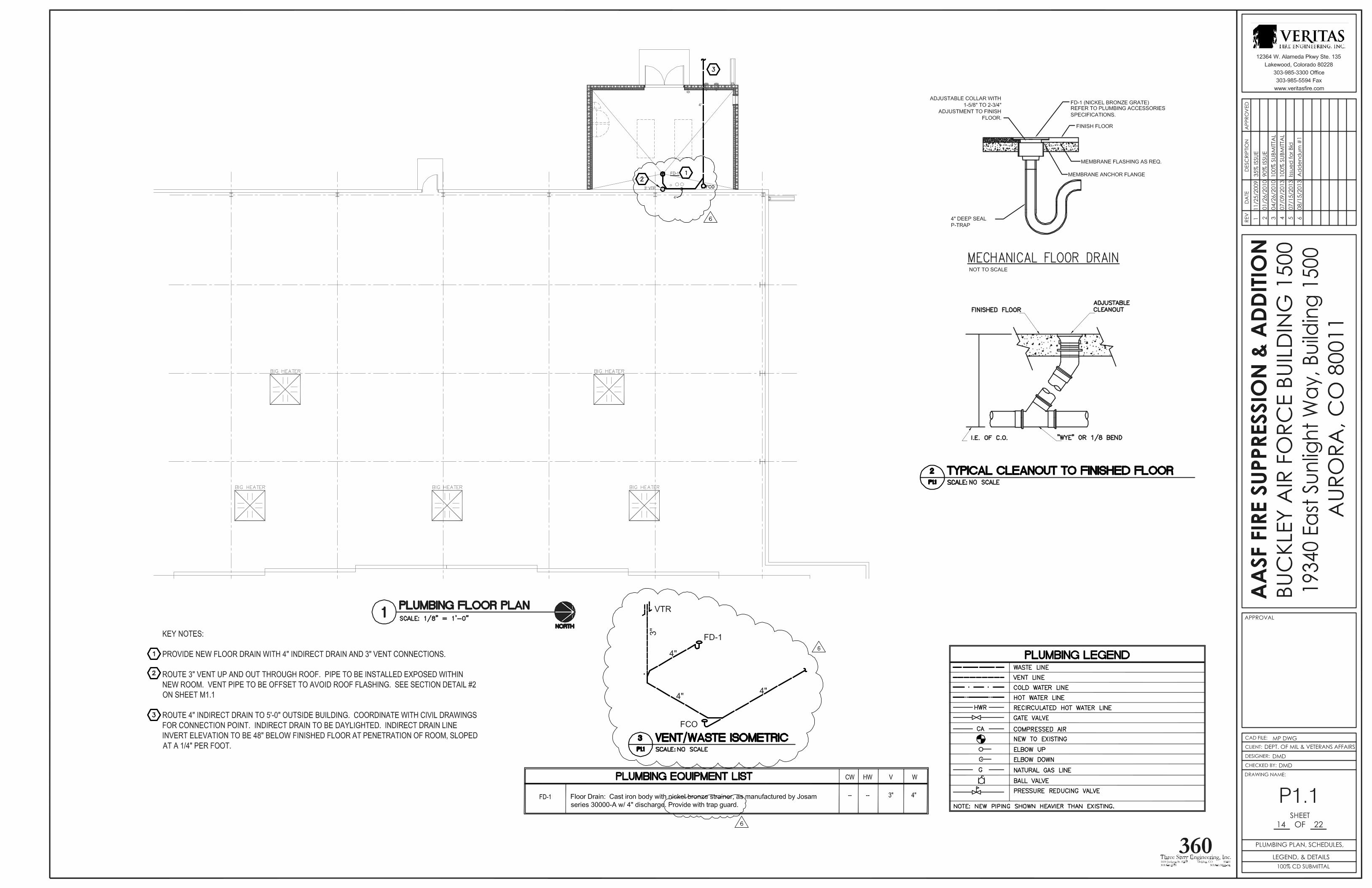
Drawings: 1. REPLACE Drawing A1.1 in its entirety. See attached.
2. REPLACE Drawing A1.2 in its entirety. See attached.
3. Drawing S0.2 - STRUCTURAL GENERAL NOTES - Design Loads Section. REVISE
Seismic Response Coefficient (Cs) from "0.08" to "0.10". REVISE Ultimate design wind speed from "115 mph" to "130 mph". REVISE Nominal design wind speed from "90 mph" to "100 mph".
4. Drawing S0.2 - STRUCTURAL GENERAL NOTES - Reinforced Concrete Section. REVISE stem wall concrete compressive strength (f`c) from "3000 psi" to "4000 psi".
5. Drawing S1.1 - FOUNDATION & FIRST FLOOR PLAN. REVISE size callouts for two footings from F3.0 to F3.5 footings.
6. Drawing S2.1 - SCHEDULE 1/S2.1 - FOOTING SCHEDULE. REVISE F3.0 line in schedule from "F3.0 3'-0 x 3'-0 x 1'-0 3-#5 EACH WAY BOTTOM" to "F3.5 3'-6 x 3'-6 x 1'-0 4-#4 EACH WAY BOTTOM".
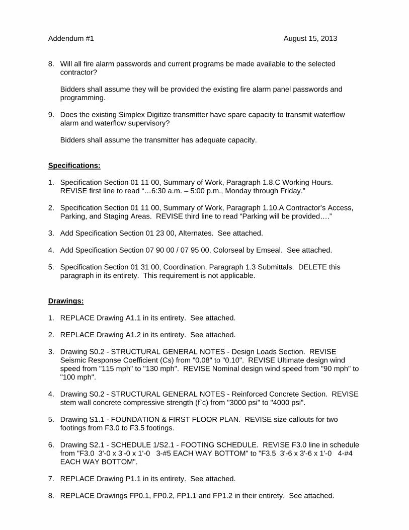
7. REPLACE Drawing P1.1 in its entirety. See attached.
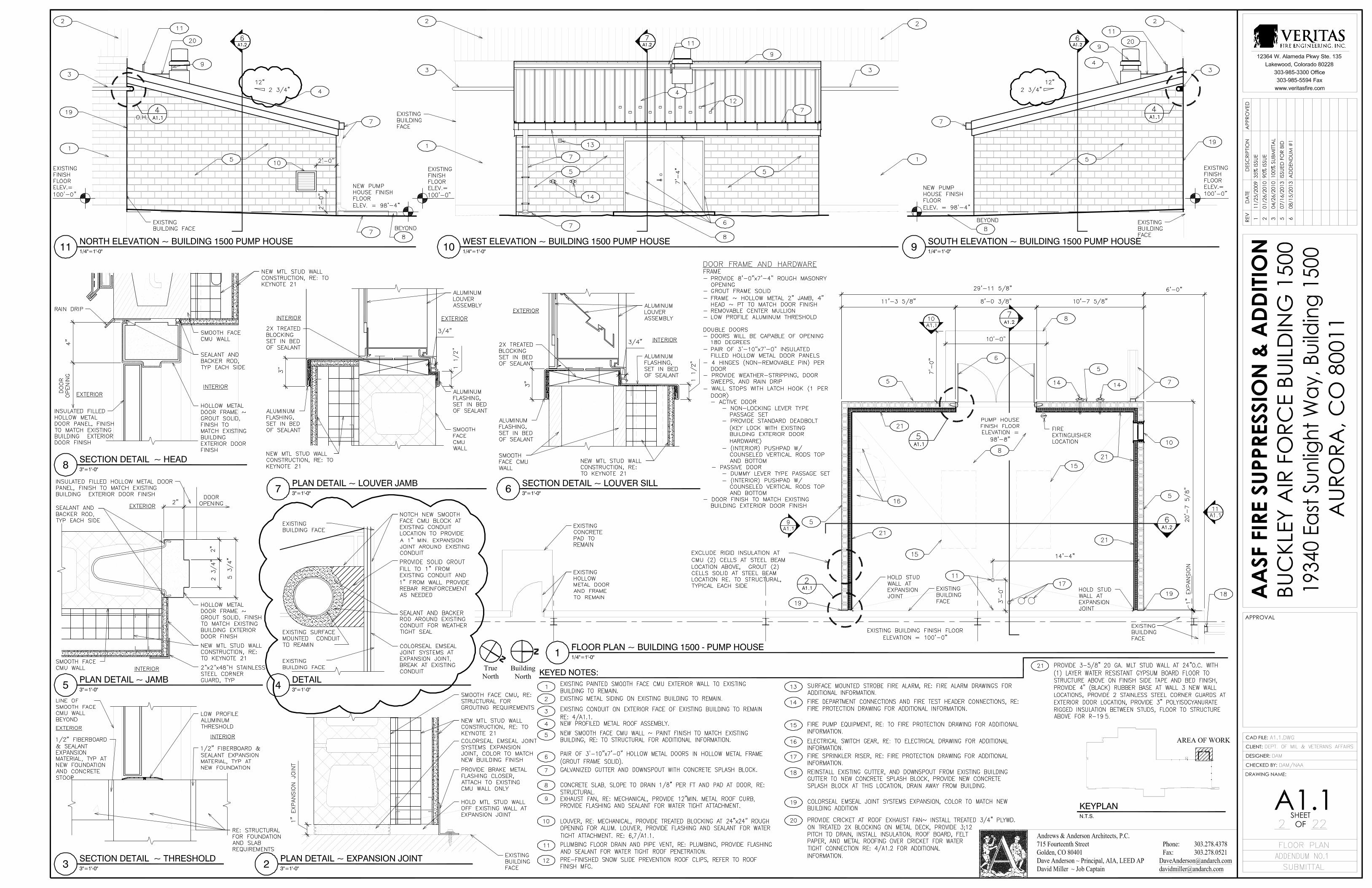
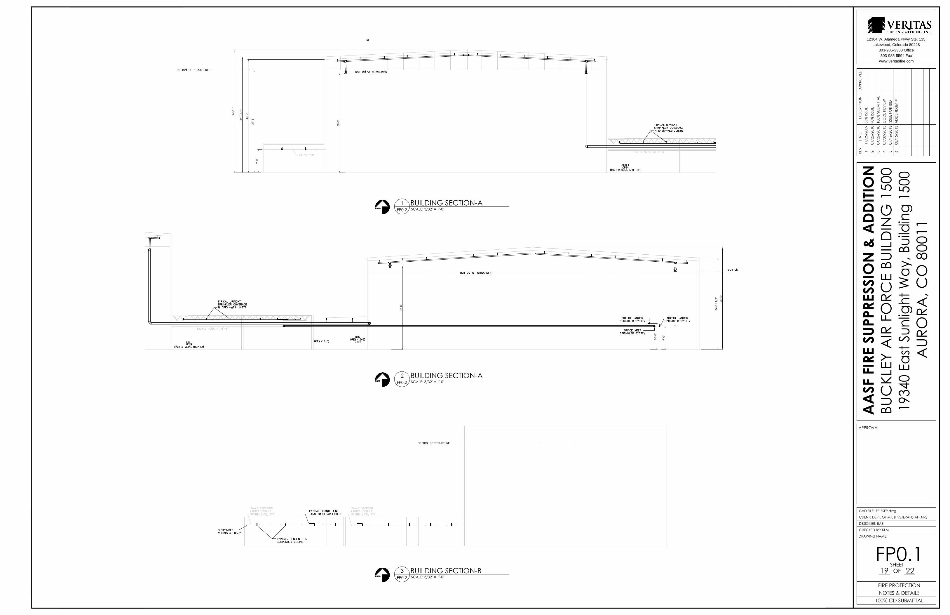
8. REPLACE Drawings FP0.1, FP0.2, FP1.1 and FP1.2 in their entirety. See attached.

Addendum #1 August 15, 2013
-LAST ITEM-

PROJECT NO. F13J39 AASF FIRE SUPPRESSION & ADDITION
012300 - 1ALTERNATES
SECTION 012300
ALTERNATES
PART 1 - GENERAL
1.1 RELATED DOCUMENTS
A. Drawings and general provisions of the Contract, including General and Supplementary Conditions and other Division 01 Specification Sections, apply to this Section.
1.2 SUMMARY
A. This Section includes administrative and procedural requirements for alternates.
1.3 DEFINITIONS
A. Alternate: An amount proposed by bidders and stated on the Bid Form for certain work defined in the Bidding Requirements that may be added to or deducted from the Base Bid amount if Owner decides to accept a corresponding change either in the amount of construction to be completed or in the products, materials, equipment, systems, or installation methods described in the Contract Documents.
1. The cost or credit for each alternate is the net addition to or deduction from the Contract Sum to incorporate alternate into the Work. No other adjustments are made to the Contract Sum.
1.4 PROCEDURES
A. Coordination: Modify or adjust affected adjacent work as necessary to completely integrate work of the alternate into Project.
1. Include as part of each alternate, miscellaneous devices, accessory objects, and similar items incidental to or required for a complete installation whether or not indicated as part of alternate.
B. Notification: Immediately following award of the Contract, notify each party involved, in writing, of the status of each alternate. Indicate if alternates have been accepted, rejected, or deferred for later consideration. Include a complete description of negotiated modifications to alternates.
C. Execute accepted alternates under the same conditions as other work of the Contract.
D. Schedule: A Schedule of Alternates is included at the end of this Section. Specification Sections referenced in schedule contain requirements for materials necessary to achieve the work described under each alternate.

PROJECT NO. F13J39 AASF FIRE SUPPRESSION & ADDITION
012300 - 2ALTERNATES
PART 2 - PRODUCTS (Not Used)
PART 3 - EXECUTION
3.1 SCHEDULE OF ALTERNATES
A. Add Alternate 1: Replace all acoustical ceiling tile in Building, except for three offices, one storage room and open office area in northeast corner of building (Drug Demand Reduction suite). New ceiling tile shall match DDR suite tile, which is Armstrong Model 763D.
END OF SECTION 012300

PROJECT NO. F13J39 07 90 00 / 07 95 00 - 1 AASF FIRE SUPPRESSION & ADDITION COLORSEAL by EMSEAL
SECTIONS 07 90 00 / 07 95 00
COLORSEAL by EMSEAL
Preformed, Pre-Compressed, Self-Expanding, Sealant System with Silicone Pre-Coated Surface Watertight, Energy-Efficient, Exterior and Interior Above-Grade Wall Joints
PART 1 – GENERAL 1.1 WORK INCLUDED
A. The work shall consist of furnishing and installing waterproof expansion joints in accordance with the details shown on the plans and the requirements of the specifications. Preformed sealant shall be silicone pre-coated, preformed, pre-compressed, self-expanding, sealant system.
B. Related Work Division 4 - Masonry Division 7 - Thermal & Moisture Protection Division 7 - Sealants, caulking and waterproofing
1.2 SUBMITTALS
A. General – Submit the following according to Division 1 Specification Section. B. Standard Submittal Package – Submit typical expansion joint drawing(s) indicating
pertinent dimensions, general construction, expansion joint opening dimensions and product information.
C. Sample of material is required at time of submittal. D. Product must be certified by independent laboratory test report to exceed the
requirements of curtain wall performance tests ASTM E330, E283-04, and E331. Product must meet or exceed hurricane-force wind loading with no deflection at both positive and negative pressures up to 4954 Pascals - equal to 200 mph winds (ASTM E330-02 procedure A).
E. Product must be certified by independent laboratory test report to meet or exceed STC 56
in an STC 72 wall and OITC 53 in an OITC 61 wall in accordance with ASTM E90-09. F. Products must be certified by independent laboratory test report to be free in composition
of any waxes or wax compounds using FTIR and DSC testing. G. Products shall be certified in writing to be: a) capable of withstanding 150°F (65°C) for 3
hours while compressed down to the minimum of movement capability dimension of the basis of design product (-25% of nominal material size) without evidence of any bleeding of impregnation medium from the material; and b) that the same material after the heat stability test and after first being cooled to room temperature will subsequently self-expand to the maximum of movement capability dimension of the basis-of-design product (+25% of nominal material size) within 24 hours at room temperature 68°F (20°C).

PROJECT NO. F13J39 07 90 00 / 07 95 00 - 2 AASF FIRE SUPPRESSION & ADDITION COLORSEAL by EMSEAL
1.3 PRODUCT DELIVERY, STORAGE AND HANDLING
A. Deliver products to site in Manufacturer’s original, intact, labeled containers. Handle and protect as necessary to prevent damage or deterioration during shipment, handling and storage. Store in accordance with manufacturer’s installation instructions.
1.4 BASIS-OF-DESIGN
A. All joints shall be designed to meet the specified performance criteria of the project as manufactured by: (USA & International) EMSEAL JOINT SYSTEMS, LTD 25 Bridle Lane, Westborough, MA 01581-2603, Toll Free: 800-526-8365. (Canada) EMSEAL, LLC 120 Carrier Drive, Toronto, Ontario, Canada M9W 5R1 Toll Free: 800-526-8365. www.emseal.com
B. Alternate manufacturers must demonstrate that their products meet or exceed the design criteria and must submit certified performance test reports performed by recognized independent laboratories as called for in section 1.02 Submittals. Submittal of alternates must be made three weeks prior to bid opening to allow proper evaluation time.
1.5 QUALITY ASSURANCE
A. The General Contractor will conduct a pre-construction meeting with all parties and trades involved in the treatment of work at and around expansion joints including, but not limited to, concrete, mechanical, electrical, HVAC, landscaping, masonry, curtain wall, waterproofing, fire-stopping, caulking, flooring and other finish trade subcontractors. All superintendents and foremen with responsibility for oversight and setting of the joint gap must attend this meeting. The General Contractor is responsible to coordinate and schedule all trades and ensure that all subcontractors understand their responsibilities in relation to expansion joints and that their work cannot impede anticipated structural movement at the expansion joints, or compromise the achievement of watertightness or life safety at expansion joints in any way.
B. Warranty – Manufacturer’s standard warranty shall apply. C. LEED Building Performance Requirements:
1. The VOC of the silicone must not exceed 40 grams/liter 2. Products must be proved by independent test report to exceed the requirements of
curtain wall performance tests ASTM E330, E283-04, and E331. Product must meet or exceed hurricane-force wind loading with no deflection at both positive and negative pressures up to 4954 Pascals - equal to 200 mph winds (ASTM E330-02 procedure A).
3. Products must be proved by independent test report to have an R-Value per 1-inch (25mm) of depth of not less than 1.8 at as-installed nominal joint size compression when tested according to ASTM C518-04.
4. Products must be proved by independent test report to ASTM E90-09 and meet or exceed an STC rating of 56 and OITC rating of 53.

PROJECT NO. F13J39 07 90 00 / 07 95 00 - 3 AASF FIRE SUPPRESSION & ADDITION COLORSEAL by EMSEAL
5. Product must be proved by independent test report to have air permeability not to exceed 0.02 L/(s.m2) at 75 Pascals as required by the Air Barrier Association of America (ABAA) in accordance with ASTM E283-04.
PART 2 – PRODUCT 2.1 GENERAL
A. Provide watertight, energy-efficient exterior and interior joints in vertical-plane walls (above-grade). Typical locations include, but are not limited to the following: applications in window perimeters, other façade penetrations such as doors, store fronts, vents, HVAC units, panel to panel joints, curtain walls, control joints, between dissimilar materials, structural expansion joints, acoustic partition barriers, and new-to-existing connections.
B. Provide COLORSEAL as manufactured by EMSEAL JOINT SYSTEMS, LTD. and as
indicated on drawings for vertical expansion joint locations.
C. Preformed sealant shall be silicone pre-coated, preformed, pre-compressed, self-expanding, sealant system. Expanding foam to be cellular foam impregnated with a water-based, non-drying, 100% acrylic dispersion. Seal shall combine factory-applied, low-modulus silicone and a backing of acrylic-impregnated expanding foam into a unified hybrid sealant system.
D. Material shall be capable of movements of +25%, -25% (50% total) of nominal material
size
E. Silicone external color facing to be factory-applied to the foam while it is partially pre-compressed to a width greater than maximum joint extension and cured before final compression. When compressed to final supplied dimension, a bellow(s) to handle movement must be created in the silicone coating. Silicone coating to be available in a range of not less than 26 standard colors for coordination with typical building materials.
F. Select the sealant system model appropriate to the movement and design requirements at
each joint location that meet the project specification or as defined by the structural engineer of record.
G. Manufacturer’s Checklist must be completed by expansion joint subcontractor and
returned to manufacturer at time of ordering material.
2.2 FABRICATION
A. COLORSEAL by EMSEAL must be supplied precompressed to less than the joint size, packaged in shrink-wrapped lengths (sticks) with a mounting adhesive on one face.
B. Directional changes and terminations into horizontal plane surfaces to be provided by
factory-manufactured universal-90-degree single units containing minimum 12-inch long leg and 6-inch long leg or custom leg on each side of the direction change or through field fabrication in strict accordance with installation instructions.

PROJECT NO. F13J39 07 90 00 / 07 95 00 - 4 AASF FIRE SUPPRESSION & ADDITION COLORSEAL by EMSEAL
PART 3 – EXECUTION 3.1 INSTALLATION
A. Preparation of the Work Area
1. The contractor shall provide properly formed and prepared expansion joint openings constructed to the exact dimensions and elevations shown on manufacturer’s standard system drawings or as shown on the contract drawings. Deviations from these dimensions will not be allowed without the written consent of the engineer of record.
2. The contractor shall clean the joint opening of all contaminants immediately prior to
installation of expansion joint system. Repair spalled, irregular or unsound joint surfaces using accepted industry practices for repair of the substrates in question. Remove protruding roughness to ensure joint sides are smooth. Ensure that there is sufficient depth to receive the full depth of the size of the COLORSEAL being installed plus at least ¼-inch (6mm) for the application of corner beads. Refer to Manufacturers Installation Guide for detailed step-by-step instructions.
3. No drilling, or screwing, or fasteners of any type are permitted to anchor the sealant
system into the substrate. 3.2 CLEAN AND PROTECT
A. Protect the system and its components during construction. Subsequent damage to the expansion joint system will be repaired at the general contractor’s expense. After work is complete, clean exposed surfaces with a suitable cleaner that will not harm or attack the finish.
END OF SECTION


DRAWING NAME:
SHEET OF
CHECKED BY:
DESIGNER:
CLIENT:
CAD FILE:
AA
SF F
IRE
SUPP
RESS
ION
& A
DDITI
ON
BUC
KLEY
AIR
FO
RCE
BUIL
DIN
G 1
500
AUR
ORA
, CO
800
11
APPROVAL
12364 W. Alameda Pkwy Ste. 135
Lakewood, Colorado 80228
303-985-3300 Office
303-985-5594 Fax
www.veritasfire.com
APP
ROV
EDD
ATE
REV
DES
CRI
PTIO
N
OF OBSTRUCTION (IN) (B)
OBSTRUCTION TO DISCHARGE (SSU/SSP).
CEILING
DISTANCE FROM SPRINKLERS
TO SIDE OF OBSTRUCTION (A)
A
B
POSITIONING OF SPRINKLERS TO
ELEVATION VIEW
DISCHARGE (SSU/SSP)
AVOID OBSTRUCTION TO
OBSTRUCTION
5'-0" AND GREATER 18"
POSITIONING OF SPRINKLERS TO AVOID
3'-6" TO LESS THAN 4'-0" 12"
4'-0" TO LESS THAN 4'-6" 14"
4'-6" TO LESS THAN 5'-0" 16-1/2"
LESS THAN 1' 0
1' TO LESS THAN 1'-6" 2-1/2"
1'-6" TO LESS THAN 2'-0" 3-1/2"
2'-0" TO LESS THAN 2'-6" 5-1/2"
2'-6" TO LESS THAN 3'-0" 7-1/2"
3'-0" TO LESS THAN 3'-6" 9-1/2"
MAXIMUM ALLOWABLE DISTANCE
OF DEFLECTOR ABOVE BOTTOM
CEILING
C
OPEN WEB STEEL
OR WOOD TRUSS
A
D
A GREATER THAN 3C or 3D
ELEVATION VIEW
(SSU/SSP)
IS GREATER)
MINIMUM DISTANCE FROM OBSTRUCTION
(USE DIMENSION C OR D WHICHEVER
TABLES & FIGURES LISTED ABOVE ARE FROM NFPA 13
INDIVIDUAL UL/FM LISTING REQUIREMENTS MAY VARY FROM THOSE
FOUND ABOVE. SEE MANUFACTURERS LITERATURE FOR COMPLETE
SPRINKLER HEAD PERFORMANCE INFORMATION
NOTE: ANY TWO (2) 'A'
DIMENSION SHALL BE EXACTLY
THE SAME. ENTRY SHALL BE
LEVEL AND TWO-HOLE.
NOTE: IT SHALL BE THE SOLE RESPONSIBILITY OF THE
UNDERGROUND INSTALLING CONTRACTOR TO INSTALL,
RESTRAINT, TEST, AND FLUSH ALL UNDERGROUND
YARD PIPING AND DEVICES IN ACCORDANCE WITH
NFPA AND ALL STATE AND LOCAL CODES.
ARAPAHOE FIRE PROTECTION SHALL BEGIN IT'S
CONTRACT AT A LEVEL 2-HOLE FLANGE INSIDE THE
BUILDING PROVIDED BY OTHERS.
SIDE VIEW
PLAN VIEW
FLOW
SIDE WALL
SID
E W
ALL
A
A
A
A
FIRE SERVICE ENTRY DETAIL1FP0.1 SCALE: NTS
RETAININGSTRAP
FIG. 69FIG. 65BEAM CLAMP
ABBREVIATIONS
ABOVE FINISHED FLOOR
BOTTOM OF BEAM
AFF
BOB
BOTTOM OF JOISTSBOJ
BOTTOM OF STEELBOS
EXPOSED TO STRUCTUREEXP
EXTENDED COVERAGE HORIZONTAL SIDEWALLECHSW
EXTENDED COVERAGE VERTICAL SIDEWALLECVSW
ELEVATIONELE
FACTORY MUTUALF/M
ABOVE FINISHED GRADEAFG
BRONZEBRZ
BRASSBRS
EXTENDED COVERAGE PENDENTECP
EXTENDED COVERAGE UPRIGHTECU
CHROMECHR
FIRE PROTECTION SYMBOL LEGEND
X
XX'-X"PIPE PLUG
PIPE HANGER
PIPE COUPLING
PIPE ELEVATION
HYDRAULIC NODE
HORN STROBE
PIPE RISE
SYSTEM RISER
PIPE CAP
PIPE REDUCER
2-WAY EARTHQUAKE BRACE
4-WAY EARTHQUAKE BRACE
PIPE FAB. TAG
HEAD ELEVATION
WELD PIPE FAB. TAG
FIRE DEPT CONNECTION
CONTROL VALVE
AUXILARY DRAIN
SHEET NOTE
PIPE DROPTC
INSP. TEST CONN.
TOP OF BEAM
TOP OF JOIST
TOB
TOJ
TOP OF STEELTOS
STANDARD SPRAY PENDENTSSP
STANDARD SPRAY UPRIGHTSSU
STANDARD SPRAY VERTICAL SIDEWALLSSVSW
WHITEWHT
ROOMRM
INTERNATIONAL FIRE CODEIFC
NATIONAL FIRE PROTECTION ASSOCIATIONNFPA
UNLESS OTHERWISE NOTEDUON
STANDARD SPRAY HORIZONTAL SIDEWALLSSHSW
UNDERWRITER'S LABORATORYU/L
INTERNATIONAL BUILDING CODEIBC
X
XX'
HANGER SPACING2FP0.1 SCALE: NTS
OBSTRUCTION INFORMATION3FP0.1 SCALE: NTS
FIRE PROTECTION HEAD LEGEND4FP0.1 SCALE: NTS
HANGER DETAILS5FP0.1 SCALE: NTS
FP0.119 22
FIRE PROTECTIONNOTES & DETAILS
100% CD SUBMITTAL
FP ESFR.dwg
DEPT. OF MIL & VETERANS AFFAIRS
BAE
KLM
111
/25/
2009
35%
ISSU
E2
01/2
6/20
1090
% IS
SUE
304
/26/
2010
100%
SUB
MITT
AL
407
/09/
2013
CO
DE
REV
IEW
507
/16/
2013
ISSU
E FO
R BI
D6
08/1
5/20
13A
DD
END
UM #
1
PROVIDE A NEW FIRE SPRINKLER AND PUMP SYSTEM FOR A RETROFITINSTALLION IN BUILDING 1500 PER ARMY ETL 1110-3-485. A NEW PUMPBUILDING ADDITION WILL HOUSE THE FIRE RISER, PUMPS AND CONTROLLERS
AASF FIRE SUPPRESSION &ADDITION19340 E. SUNLIGHT WAYBUILDING 1500AURORA, COLORADO 80011
FIRE SPRINKLER SYSTEM SUBMITTAL
BUCKLEY AIR FORCEFIRE DEPARTMENT
MAIN BUILDING, WETPUMP HOUSE, WET
SYSTEM TYPE:
SPRINKLERED:
NUMBER OF STORIES:
OCCUPANCY GROUP:
39'-3
"43'-3
"
44'-2
1/2
"
46'-1
1"
9'-0
"
38'-0
"
34'-1
1 1/
2"39
'-0"
9'-0
"
10'-0
"
32'-0
"
DRAWING NAME:
SHEET OF
CHECKED BY:
DESIGNER:
CLIENT:
CAD FILE:
AA
SF F
IRE
SUPP
RESS
ION
& A
DDITI
ON
BUC
KLEY
AIR
FO
RCE
BUIL
DIN
G 1
500
AUR
ORA
, CO
800
11
APPROVAL
12364 W. Alameda Pkwy Ste. 135
Lakewood, Colorado 80228
303-985-3300 Office
303-985-5594 Fax
www.veritasfire.com
APP
ROV
EDD
ATE
REV
DES
CRI
PTIO
N
BUILDING SECTION-A1FP0.2 SCALE: 3/32" = 1'-0"
BUILDING SECTION-B3FP0.2 SCALE: 3/32" = 1'-0"
BUILDING SECTION-A2FP0.2 SCALE: 3/32" = 1'-0"
FP0.119 22
FIRE PROTECTIONNOTES & DETAILS
100% CD SUBMITTAL
FP ESFR.dwg
DEPT. OF MIL & VETERANS AFFAIRS
BAE
KLM
111
/25/
2009
35%
ISSU
E2
01/2
6/20
1090
% IS
SUE
304
/26/
2010
100%
SUB
MITT
AL
407
/09/
2013
CO
DE
REV
IEW
507
/16/
2013
ISSU
E FO
R BI
D6
08/1
5/20
13A
DD
END
UM #
1

5'-1
1"
REMOTE AREA 3
REMOTE AREA 1
1FP1.1 SCALE: 1/8" = 1'-0"
DRAWING NAME:
SHEET OF
CHECKED BY:
DESIGNER:
CLIENT:
CAD FILE:
AA
SF F
IRE
SUPP
RESS
ION
& A
DDITI
ON
BUC
KLEY
AIR
FO
RCE
BUIL
DIN
G 1
500
AUR
ORA
, CO
800
11
APPROVAL
12364 W. Alameda Pkwy Ste. 135
Lakewood, Colorado 80228
303-985-3300 Office
303-985-5594 Fax
www.veritasfire.com
APP
ROV
EDD
ATE
REV
DES
CRI
PTIO
N
FIRE SPRINKLERPIPING PLAN SOUTH
FP0.119 22
FIRE PROTECTIONNOTES & DETAILS
100% CD SUBMITTAL
FP ESFR.dwg
DEPT. OF MIL & VETERANS AFFAIRS
BAE
KLM
111
/25/
2009
35%
ISSU
E2
01/2
6/20
1090
% IS
SUE
304
/26/
2010
100%
SUB
MITT
AL
407
/09/
2013
CO
DE
REV
IEW
507
/16/
2013
ISSU
E FO
R BI
D6
08/1
5/20
13A
DD
END
UM #
1
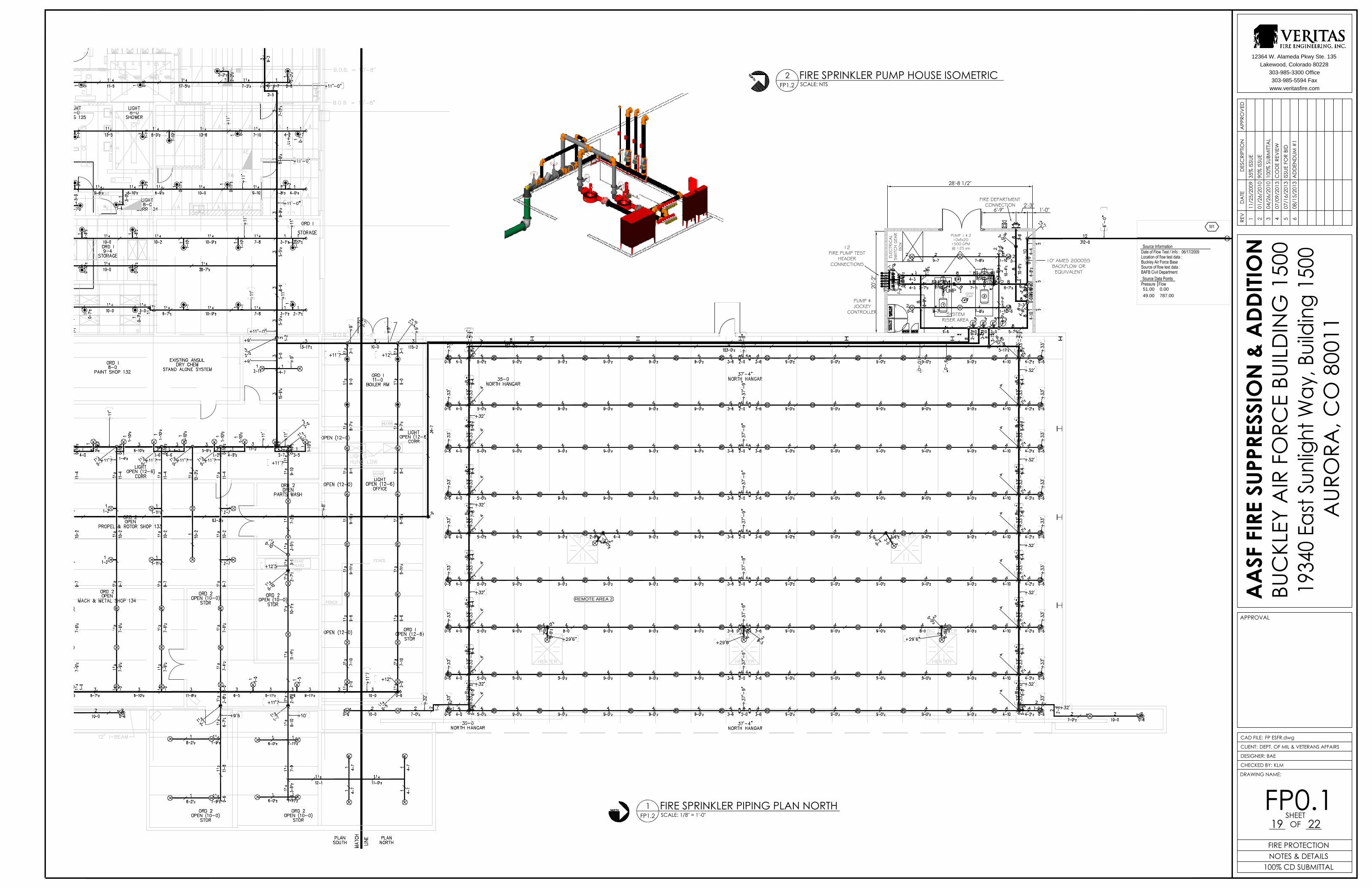
PUMP 1 & 210x8x20
1500 GPM@ 125 psi
SYSTEMRISER AREA
FIRE DEPARTMENTCONNECTION
PUMP &JOCKEY
CONTROLLER
JOCKEYPUMP
12FIRE PUMP TEST
HEADERCONNECTIONS
28'-8 1/2"
20'-2
"
1'-0"2'-3"
6'-9"
ELEC
TRIC
AL
SW
ITCH G
EAR
BO
X
10" AMES 2000SSBACKFLOW OREQUIVALENT
REMOTE AREA 2
51.00 0.00
49.00 787.00
FIRE SPRINKLER PIPING PLAN NORTH1FP1.2 SCALE: 1/8" = 1'-0"
DRAWING NAME:
SHEET OF
CHECKED BY:
DESIGNER:
CLIENT:
CAD FILE:
AA
SF F
IRE
SUPP
RESS
ION
& A
DDITI
ON
BUC
KLEY
AIR
FO
RCE
BUIL
DIN
G 1
500
AUR
ORA
, CO
800
11
APPROVAL
12364 W. Alameda Pkwy Ste. 135
Lakewood, Colorado 80228
303-985-3300 Office
303-985-5594 Fax
www.veritasfire.com
APP
ROV
EDD
ATE
REV
DES
CRI
PTIO
N
FIRE SPRINKLER PUMP HOUSE ISOMETRIC2FP1.2 SCALE: NTS
FP0.119 22
FIRE PROTECTIONNOTES & DETAILS
100% CD SUBMITTAL
FP ESFR.dwg
DEPT. OF MIL & VETERANS AFFAIRS
BAE
KLM
111
/25/
2009
35%
ISSU
E2
01/2
6/20
1090
% IS
SUE
304
/26/
2010
100%
SUB
MITT
AL
407
/09/
2013
CO
DE
REV
IEW
507
/16/
2013
ISSU
E FO
R BI
D6
08/1
5/20
13A
DD
END
UM #
1