programma tm1800tm circuit breaker analyzer … tm1800tm circuit breaker analyzer system ......
TRANSCRIPT

ProgrammaTM1800TM Circuit Breaker Analyzer System
Modular based design — user configurableTM1800 from nine different modules
Built in PC with CABA Local software —advanced testing with predefined breaker testplans (templates), onsite measurement viewand analysis
Dual ground testing using DCM module —increased safety with both sides of breakergrounded
Fast and easy testing — Select-Connect-Inspectworkflow and high level user interface
Graphical results for quick interpretation —timing and motion measurements, coil currents
USB and Ethernet communication interface —for quick back up, LAN connection and printeroptions
CABA Win — for advanced data analysis,database interface and common test dataarchive
ProgrammaTM1800 Circuit Breaker Analyzer System
DESCRIPTIONThe TM1800TM is the instrument platform for circuit breakermaintenance, based on more than 20 years’ experience ofover 4,000 delivered breaker analyzers. The modularconstruction makes it possible to configure the TM1800 for measurements on all known types of circuit breakers in operation in today’s power world.
The robust design contains powerful technology thatstreamlines circuit breaker testing. Sophisticatedmeasurement modules enable great time savings as manyparameters can be measured simultaneously, eliminatingthe need for new setup each time. DualGroundTM testingusing the new Dynamic Capacitive Measurement (DCM)module makes the testing safe and time saving, bykeeping the circuit breaker grounded on both sidesthroughout the test. The DCM module uses a measuringtechnology called Dynamic Capacitive Measurement.
Timing M/R module uses Active Interference Suppressiontechnology to obtain correct timing and accurate Pre-Insertion Resistance (PIR) values in high voltagesubstations having coupled interference currents.
An adaptive, user-interactive software suite supportsactivities from timing, simply turning a knob without theneed for presetting, to advanced help functions forconnection to the test specimen. A full keyboard and 8”color screen is the front end of the high-level userinterface. The Select-Connect-Inspect workflow directsusers to fast results in three easy steps, therefore, allowingtesting to be easier to learn and perform.
The system also offers full connection capability to thelocal network and printers, etc.
Testing with DualGroundElectricity deregulation changes the business environmentfor utilities, switchgear owners and service companies.Deregulation has been shown to lead directly to increasedemphasis on efficiency of operations, maintenance andservice levels. Globalization of business brings newchallenges and new requirements for increased emphasison health, safety and environmental compliance.Experience has also shown demands for shorter timeperiods for testing, while the switchgear is less and lessavailable to be taken out of service.
The safety aspectNetwork operators and service companies need tomaintain and develop their industry safety record. EminentInternational bodies including the IEEE® and IEC®, NationalSafety agencies and Trade Unions increases the demandson safety. During deregulation, applicable safetyregulations have been clarified and the application ofexisting rules has tightened. Keeping a good safety recordis becoming a crucial asset in attracting investors andcustomers.
In all substations the capacitive coupling from live highvoltage conductors induce harmful/lethal currents in allparallel conductors. Grounding both sides of the test objectwill lead the induced current to earth and provide a safearea for the test personnel. See Figures 1 and 2.

Both sides groundedThe best way to provide safety in circuit breaker testing isto keep both sides of the circuit breaker groundedthroughout the test. This allows the test to be faster,performed easier and safer. Minimum time shall be spentin the substation and focus shall be on the test rather thanthe equipment.
The DualGroundTM testing method is available for all testson all circuit breakers.
The following table indicates the Programma instrumentsthat the TM1800 works in conjunction with:
Contact resistance MJÖLNER
Timing TM1800 with DCM
Motion TM1800
Dynamic Resistance TM1800 with DRM1800Measurement (DRM)
Vibration CABA Win Vibration
ProgrammaTM1800 Circuit Breaker Analyzer System
Equipment and methods thatsupports DualGroundTM testing areassociated with the DualGroundsymbol. This symbol certifies theuse of groundbreaking technologyand methods that enables a safe,fast and easy workflow with bothsides grounded throughout the test.
Test procedures – Comparison betweenConventional and DualGround Testing
1 Site preparation (isolate work area, apply safetyground, issue permit to work)
2 Hook up test equipment. Issue sanction for test
3 Authorized person removes the ground (left outwhen testing with DualGround)
Dual Ground
Conventional Testing
Two risky steps (3 & 5) in the workflow are left out and one step is made safer. Result: safer, faster and easier testing.
4 Perform testing
5 Authorized person applies ground (left out whentesting with DualGround)
6 Cancel sanction for test. Disconnect test equipment
7 Site closing (cancel permit to work, disconnectground)
Figure 1. With only one side grounded the induced current canreach values high enough to be harmful or lethal for humans.
Figure 2. Testing is much safer using the DCM module andDualGround.

Speed is calculated between two points on the motioncurve. The upper point is defined as a distance in length,degrees or percentage of movement from a) the breaker’sclosed position, or b) the contact-closure or contact-separation point. The time that elapses between these twopoints ranges from 10 to 20 ms, which corresponds to 1-2zero-crossovers.
The distance throughout which the breaker’s electric arcmust be extinguished is usually called the arcing zone.From the motion curve, a velocity or acceleration curvecan be calculated in order to reveal even marginal changesthat may have taken place in the breaker mechanism.
Damping is an important parameter for the high energyoperating mechanisms used to open and close a circuitbreaker. If the damping device does not functionsatisfactorily, the powerful mechanical strains that developcan shorten breaker service life and/or cause seriousdamage. The damping of opening operations is usuallymeasured as a second speed, but it can also be based onthe time that elapses between two points just above thebreaker’s open position. See Figure 3.
Coil currentsThese can be measured on a routine basis to detectpotential mechanical and/or electrical problems inactuating (trip & close) coils well in advance beforedeveloping actual faults. The coil’s maximum current (if current is permitted to reach its highest value) is adirect function of the coil’s resistance and actuatingvoltage. This test indicates whether or not a winding has been short-circuited. See Figure 4.
ProgrammaTM1800 Circuit Breaker Analyzer System
APPLICATIONSTiming measurementsSimultaneous measurements within a single phase areimportant in situations where a number of contacts areconnected in series. Here, the breaker becomes a voltagedivider when it opens a circuit. If the time differences aretoo great, the voltage can be too high across one contact.The tolerance for most types of breakers is less than 2 ms.
The time tolerance for simultaneous measurementsbetween phases is greater for a 3-phase powertransmission system running at 60 Hz since there is always2.77 ms between zero-crossovers. Still, the time toleranceis usually specified as less than 2 ms, even for suchsystems. It should also be noted that breakers that performsynchronized breaking must meet more stringentrequirements in both of the previously stated situations.
There are no generalized time limits for the timerelationships between main and auxiliary contacts, but it isstill important to understand and check their operation.The purpose of an auxiliary contact is to close and open acircuit. Such a circuit might enable a closing coil when abreaker is about to perform a closing operation and thenopen the circuit immediately after the operation starts,thereby preventing coil burnout.
The "a" contact must close well in advance of the closingof the main contact. The "b" contact must open when theoperating mechanism has released its stored energy inorder to close the breaker. The breaker manufacturer willbe able to provide detailed information about this cycle.
Motion measurementsA high-voltage breaker is designed to interrupt a specificshort-circuit current, and this requires operation at a givenspeed in order to build up an adequate cooling stream ofair, oil, vacuum or gas (depending on the type of breaker).This stream cools the electric arc sufficiently to interruptthe current at the next zero-crossover. It is important tointerrupt the current in such a way that the arc will not re-strike before the breaker contact has entered thedamping zone.
Figure 3. Motion diagram and timing graphs for a close-openoperation
1 Trip coil energized
2 Armature travel
3-4 Armature operates trip latch
4-5 Armature completes its travel
6 Change in coil inductance
7 Proportional to dc coil
resistance
8 Auxiliary contact opens
9 Current decay
Figure 4. Example of coil current on circuit breaker

When a voltage is being applied across a coil, the currentcurve first shows a straight transition whose rate of risedepends on the coil’s electrical characteristic and thesupply voltage (points 1-2). When the coil armature (whichactuates the latch on the operating mechanism’s energypackage) starts to move, the electrical relationship changesand the coil current drops (points 3-5). When the armaturehits its mechanical end position, the coil current risesproportionally to the coil voltage (points 5-8). Theauxiliary contact then opens the circuit and the coil current drops to zero with a current decay caused by the inductance in the circuit (points 8-9).
The peak value of the first, lower current peak is related to the fully saturated coil current (max current), and thisrelationship gives an indication of the spread to the lowesttripping voltage. If the coil was to reach its maximumcurrent before the armature and latch start to move, thebreaker would not be tripped. It is important to note thatthe relationship between the two current peaks varies,particularly with temperature. This also applies to thelowest tripping voltage.
Dynamic Resistance Measurement (DRM)A circuit breaker will have the arcing contact wear bynormal operation as well as when breaking short-circuitcurrents. If the arcing contact is too short or otherwise inpoor condition, then the breaker soon becomes unreliable.Main contact surfaces can be deteriorated by arcingresulting in increased resistance, excessive heating and inworst-case failure.
The main contact resistance is measured dynamically overan open or close operation in DRM. With DRMmeasurement the arcing contact length can be reliablyestimated. The only real alternative in finding the length ofthe arcing contact is dismantling the circuit breaker.
A reliable DRM interpretation requires high DC test currentand a circuit breaker analyzer with good measurementresolution. See Figure 5.
Testing with DualGroundTM is applicable.
Vibration analysisVibration analysis is a non-invasive method using anacceleration sensor without moving parts. The breaker canstay in service during the test. A single Open-Closeoperation is all that is required for the measurement. Thefirst operation is different compared to the second andthird because of corrosion and other metal to metalcontact issues. Vibration is an excellent method to capturethe first operation after long periods of breaker non-operation.
The analysis compares the vibration time series with earliertaken reference. The vibration method detects faults thatcan hardly be indicated with conventional methods. But ifconventional data such as contact time, travel curve, coilcurrent and voltage are available in addition to thevibration data even more precise condition assessment ispossible. The vibration data is stored together withavailable conventional data.
The Vibration method is published in CIGRÉ and IEEE®
papers. Vibration can be performed under very safeconditions for the test technician as both sides can begrounded throughout the test. Also less climbing isrequired since no access to the breaker contact system isneeded, the acceleration sensor is easily mounted on thebreaker.
Testing with DualGroundTM is applicable.
ProgrammaTM1800 Circuit Breaker Analyzer System
Figure 5. DRM is a reliable method to estimate the length/wear of the arcing contact.The DRM1800 provides high current and the TM1800 gives an accurate measurementwith very good resolution. Besides, it is possible to use DualGround testing.

Select – Connect – InspectWorking with TM1800 means fast, safe and easy testing.Testing is done with a three-step process.
1. Select a suitable template from the template librarydepending on number of contacts per phase, motion ornot, resistor contacts and more.
2. Connect the test leads according to the graphical helpscreen.
3. Turn the “Measure” knob. The measurement isperformed, analyzed and the results will be displayed onthe screen. Magnification and compare functions areavailable.
For more advanced setup there is still the opportunity tocontrol all the details in the measurement. The largenumber of general purpose templates cover most circuitbreakers found throughout the world. It is also possible toselect a custom template with special adaptions. The usercan edit templates with assistance from customer support.This is a very powerful tool to customize TM1800 for fast,safe and easy work according to the user’s needs in everydetail.
After the test it is possible to print a test report, either fromthe TM1800 printer module or using CABA Win on a PC.With CABA Win the user can make a more advancedanalysis of the data. CABA Win is also the archive forcommon test data and interface to CEBEX. With CEBEXthe test is stored in a database.
FEATURES AND BENEFITS Circuit breaker analyzer test set TM1800 performs
timing, travel and motion tests, dynamic and staticresistance measurement and coil current measurements.
Light and portable TM1800 unit with user configurablemodules to suit different demands, testing andapplications.
Built in PC with keyboard and mouse, HDD modulewith removable hard drive to store more than 1000 testresults.
Quick and easy testing — simply a turn of “Measure”knob provides instant graphical results andmeasurements.
All testing done with same connections — save “out ofservice” time of circuit breaker and less physical laborfor operator as no need of reconnecting the unit fordifferent tests.
Dual ground testing — safest way of testing bygrounding both sides of the circuit breakers.
ProgrammaTM1800 Circuit Breaker Analyzer System
SelectSelect the templatesuitable for the testand circuit breakerfrom the library.
ConnectConnect test leadsand cablesaccording to display.Separate help screenper cable.
InspectTurn the knob andthe measurement isdisplayed on thescreen ready forinspection.
CABA local circuit breaker analyzing software — pre-defined and custom based circuit breaker templates,connection diagram through graphical help screen.
Active Interference Suppression technique used forcorrect timing and accurate PIR values in high voltagesubstations having coupled interference currents.
Unique DMC measuring technology — DynamicCapacitive Measurement for dual ground testing.
Data back up and transfer through USB and Ethernetcommunication.
Print a graphical and tabular test report through printermodule or CABA win software on a PC.
CABA Win software — can be used for advanced dataanalysis, archive for common test data and interface to CEBEX.
Multiple language support — English, French, German,Spanish, Swedish

MODULAR DESIGN OF THE TM1800
BASIC UNIT, Cat. No. CG-19090The modularized design makes it very flexible to userneeds and enables reconfiguration for new demands andupgrade with new functionality. The user can configureTM1800 to a complete test set based upon user specificneed. The firmware, CABA Local, guides the user toefficient circuit breaker testing.
All inputs and outputs on the TM1800 and the modules are designed to withstand the harsh environment in high-voltage substations and industrial environments.
With built-in protection circuits and software-designedprotection the TM1800 has built-in suppression to protectagainst failures caused by over-voltages generated in thesubstations and high-voltage environments.
The HDD module is a part of the basic unit and containsthe hard drive with all data and software setup. It caneasily be removed and changed.
ProgrammaTM1800 Circuit Breaker Analyzer System
Some of the key features of configurable TM1800 unit are: Eight user configurable slots for modules Temperature sensor connection Quick backup on USB device Trigger inputs and outputs Outputs for warning signal Earth (Ground) connection Communication interfaces (USB, Ethernet, etc)
BASIC UNIT SPECIFICATIONSPower supply (nominal) 100-240 V AC, 50/60 HzPower consumption 250 VA (max)Dimensions 515 x 173 x 452 mm
(20.3” x 6.8” x 17.8”)Weight 15.5 kg (34.2 lbs)
External InputTrig in
Time accuracy: ±0.1 msVoltage modeInput range: 0 to 250 V AC/DCThreshold level: user configurable in software steps of 1 VContact modeOpen circuit voltage: 35 V DC ±20%Short circuit current: 10 to 40 mAThreshold level: 1 - 2 kΩ
External OutputTrig out
Number of channels: 3 (Trig Out, DRM, Warning)Pulse duration: 1-999 ms, user configurable in steps of 1 msVoltage modeOpen circuit voltage: 12 V DC ±5%Voltage at 0.5A: 9 V DC ±10%Max short circuit current: 1.5 AContact modeMax switching current: 0.5 A at 12 V and resistive loadVoltage at 0.5A: 9 V DC ±10%Max short circuit current: 1.5 A
DRM (for DRM1800 only)Warning
Relay: for lamp or hornPre-operation warning: 0 0 999 s, user configurable in steps of 1 s
Voltage modeOutput voltage: 12 V DC ±10%Voltage at 0.5A: 9 V DC ±10%Short circuit current: Fuse 1 A DC fasting acting type (F1H250V)Contact modeMax switching current: 1 A at 12 V and resistive load
Communication InterfaceUSB Ver. 1.1Ethernet 100 base-Tx Fast EthernetExternal screen SVGA, up to 800 x 600 at 24 bit color,
32 MB SDRAM
HMI, Human-Machine InterfaceCABA Local Circuit breaker analyzing software
Languages English, French, German, Spanish, SwedishDisplay Transreflecting to increase visibility in direct
sunlightDiag. Size 21 cm (8”)
Keyboard Built-in
SPECIFICATIONS
GENERALSpecifications are valid after 30 minutes warm up time. Systemtime base drift 0.001% per year. Specifications are subject tochange without notice.
Environment
Application fieldFor use in high-voltage substations and industrial environments.
TemperatureOperating: -10°C to +50°C (+14°F to +122°F)Storage & transport: -55°C to +70°C (-67°F to +158°F)Humidity: 5% – 95% RH, non-condensing
CE-markingLVD Low Voltage Directive 73/3/EEC am.
by 93/68/EEC EMC EMC Directive 89/336/EEC am. by
91/263/EEC, 92/31/EEC and 93/68/EEC

ProgrammaTM1800 Circuit Breaker Analyzer System
TIMING M/R MODULE, Cat. No. CG-19080The timing M/R module uses one hook-up for testing allthe important timing parameters of a contact without theneed of reconnection or special set-ups.
One timing M/R module willmeasure up to six contactsincluding linear PIR contacts.
The timing M/R module is using patented ActiveInterference Suppression toobtain correct timing andaccurate PIR values regardless of interference in high voltagesubstations.
The module is equipped withthree galvanically isolated XLRfemale connectors with built-involtage source.
Six channels per module
Active Interference Suppression
High resolution and up to 40 kHz sampling
Main and parallel resistor contact timing
Resistance value of parallel resistors
TIMING M/R MODULE SPECIFICATIONSGeneralNo. of channels 6 (2 voltage ranges per channel when
used in voltage mode)Time base inaccuracy ±0.01% of reading ±1 sample intervalMin resolution 0.05 msMax sample rate 40 kHz Measurement time 16 s at 20 kHz sample rate,
32 s at 10 kHz sample rate,200 s at 10 kHz sample rate using datacompressionData compression is available at samplerates up to 20 kHz
Weight 0.8 kg (1.8 lbs)
Timing of main and resistive contactsOpen circuit voltage 6 V or 26 V ±10% (toggling at every
second sample at sample rates from 10kHz and upwards)
Short circuit current 9.7 mA or 42 mA ±10%Status threshold
Main: Closed < 10 Ω < openMain and resistor: main <10 Ω <PIR < 10 kΩ < Open
PIR resistance measurementSupported PIR types Linear PIRMeasurement range 10 Ω to 10 kΩAccuracy ±10% of reading ±0.1% of range
CONTROL MODULE, Cat. No. CG-19030The control module controls the operation of the circuitbreaker. Various circuit breakeroperation sequences can beperformed accurately and withoutany bounce.
This module also measuresimportant parameters during thetest. Coil current, control voltage,coil resistance for each phase onone phase operated circuitbreaker is automatically measuredwithout any additional test leadconnections. Auxiliary contacttiming is measured for singleoperation.
Three independent contactfunctions per module
Pre-programmed sequences Close, Open, Close/Open, Open/Close, Open/Close/Open
Timing of a and b auxiliary contacts for single operation
CONTROL MODULE SPECIFICATIONSGeneralNo. of channels 3Time base Accuracy ±0.01% of reading ±1 sample intervalMax sample rate 10 kHz Measurement time 19 s at 10 kHz sample rate,
39 s at 5 kHz sample rate,200 s at 10 kHz sample rate using datacompression
Weight 1.0 kg (2.2 lbs)
Non-bouncing switchMax current 60 A AC/DC, pulse < 100 msFuse 15 A DCDuration User configurable in steps of 1 ms Delay User configurable in steps of 1 ms
Current measurementMeasurement range 0 to 60 A AC/DCResolution 16 bits (15 bits at data compression)Accuracy ±2% of reading ±0.1% of range
Voltage measurementMeasurement range 0 to 250 A AC/DCResolution 20 mV (40 mV at data compression)Accuracy ±1% of reading ±0.1% of range

ProgrammaTM1800 Circuit Breaker Analyzer System
DCM MODULE, Cat. No. CG-19190The DCM module enables DualGround testing. Thisincreases safety and also makes testing easier. This moduleuses a patented measuring technology called DynamicCapacitive Measurement.
Each pair of a Timing M/R andDCM module provides up to sixchannels. Each channel requiresa special DCM cable withintegrated electronics.
The TM1800 system can beequipped with multiple DCMand Timing M/R module pairsthat enable timing measurementon up to 18 contacts.
Six channels per module
Timing test using DualGround
Safe, fast and easy testing
DCM MODULE SPECIFICATIONS
GeneralNo. of channels 6Weight 625 g (1.4 lbs)
OutputVoltage 0 to 5 V rms acCurrent 0 to 20 mA rms ac
DIGITAL MODULE, Cat. No. CG-19040With digital/incrementaltransducers motion and othermeasurement becomes evenmore accurate, faster and easier.The digital module enables use of incremental rotary or lineartransducers for measurementslike motion, velocity anddamping characteristics of circuit breakers.
Six channels per module
Incremental transducers with RS422
Up to ±32000 pulses resolution
Up to 20 kHz sampling
DIGITAL MODULESPECIFICATIONSGeneralNo. of channels 6Supported types Incremental transducers, RS422Time base accuracy ±0.01% of reading ±1 sample intervalMax sample rate 20 kHz Measurement time 16 s at 20 kHz sample rate,
32 s at 10 kHz sample rate,200 s at 10 kHz sample rate using datacompression
Weight 0.7 kg (1.5 lbs)
OutputVoltage 5 V DC ±5% or 12 V DC ±5%Max output current 200 mA
Digital outputRange ±32,000 pulsesResolution 1 pulseAccuracy ±1 pulse
ANALOG MODULE, Cat. No. CG-19000The analog module measuresany analog entity from atransducer mounted on a circuitbreaker. It enablesmeasurements of motion, speed,current, voltage, pressure,vibration etc. Motionmeasurements are taken withstandard linear or rotarytransducers, shunts and 4-20 mAtransducers. High level userinterface makes measurementfaster and easier.
Universal transducers andspecialized transducers withconversion tables are availablefor numerous circuit breakers.
Three channels per module
Supports industrial analog transducers
ANALOG MODULE SPECIFICATIONS
GeneralNo. of channels 3Time base accuracy ±0.01% of reading ±1 sample intervalMax sample rate 40 kHz Measurement time 10 s at 40 kHz sample rate,
20 s at 20 kHz sample rate,200 s at 10 kHz sample rate using datacompression
TransducerResistance 500 Ω - 10 kΩ at 10 V outputWeight 0.8 kg (1.8 lbs)
OutputVoltage output 10 V dc ±5%, 24 V DC ±5%Max output current 20 to 30 mA
Current measurementMeasurement range 0 to 20 mA DCResolution 16 bits (15 bits at data compression)Accuracy ±1% of reading ±0.1% of range
Voltage measurementInput voltage range 0 to 250 V AC/DCMeasurement range ±10 V dc, 0 to 250 V AC/DCResolution 16 bits (15 bits at data compression)Accuracy
250 V range: ±1% of reading ±0.1% of range10 V range: ±0.1% of reading ±0.1% of range
ProgrammaTM1800 Circuit Breaker Analyzer System
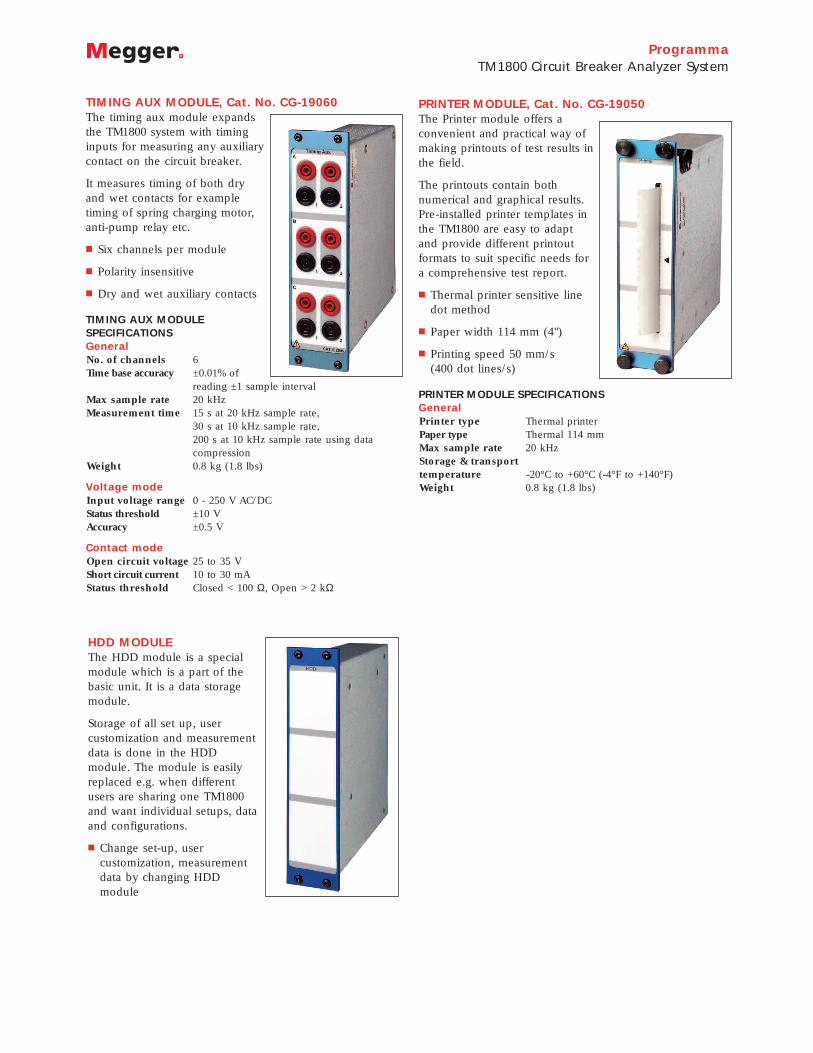
TIMING AUX MODULE, Cat. No. CG-19060The timing aux module expandsthe TM1800 system with timinginputs for measuring any auxiliarycontact on the circuit breaker.
It measures timing of both dryand wet contacts for exampletiming of spring charging motor,anti-pump relay etc.
Six channels per module
Polarity insensitive
Dry and wet auxiliary contacts
TIMING AUX MODULE SPECIFICATIONSGeneralNo. of channels 6Time base accuracy ±0.01% of
reading ±1 sample intervalMax sample rate 20 kHz Measurement time 15 s at 20 kHz sample rate,
30 s at 10 kHz sample rate,200 s at 10 kHz sample rate using datacompression
Weight 0.8 kg (1.8 lbs)
Voltage modeInput voltage range 0 - 250 V AC/DCStatus threshold ±10 VAccuracy ±0.5 V
Contact modeOpen circuit voltage 25 to 35 VShort circuit current 10 to 30 mAStatus threshold Closed < 100 Ω, Open > 2 kΩ
HDD MODULEThe HDD module is a specialmodule which is a part of thebasic unit. It is a data storagemodule.
Storage of all set up, usercustomization and measurementdata is done in the HDDmodule. The module is easilyreplaced e.g. when differentusers are sharing one TM1800and want individual setups, dataand configurations.
Change set-up, usercustomization, measurementdata by changing HDDmodule
PRINTER MODULE, Cat. No. CG-19050The Printer module offers aconvenient and practical way ofmaking printouts of test results inthe field.
The printouts contain bothnumerical and graphical results.Pre-installed printer templates inthe TM1800 are easy to adaptand provide different printoutformats to suit specific needs fora comprehensive test report.
Thermal printer sensitive linedot method
Paper width 114 mm (4")
Printing speed 50 mm/s (400 dot lines/s)
PRINTER MODULE SPECIFICATIONSGeneralPrinter type Thermal printerPaper type Thermal 114 mmMax sample rate 20 kHz Storage & transporttemperature -20°C to +60°C (-4°F to +140°F)Weight 0.8 kg (1.8 lbs)

ProgrammaTM1800 Circuit Breaker Analyzer System
ORDERING INFORMATION
Item Cat. No.
TM1800 Basic Unit Complete with: HDD module, CABA local, transport case, USB memory CG-19090
Control Module (3 independent contacts)Including: 3 cable sets, 5 m (16 ft), GA-00877 CG-19030
Timing M/R Module (6 channels + 6 PIR)Including: 3 cable sets, 5 m (16 ft) total length, 1.5 m (4.9 ft) spread, GA-00850 CG-19080
DCM Module (3 channels)Including: 3 DCM-cables, 12 m (39 ft) CG-19190
Analog Module (3 channels)Including: 3 cable sets, 10 m (33 ft), GA-01005 CG-19000
Digital Module (6 channels) CG-19040
Timing Aux Module (6 channels)Including: 3 cable sets, 5 m (16 ft), GA-00870 CG-19060
Printer ModuleIncluding: paper spool, GC-00040 CG-19050
TM1800 – Configurations
TM1800 Standard, complete with: TM1800 Basic unit, +1 Control Module, 1 Timing M/R module, 1 Analog module CG-19290
TM1800 Standard – for DualGround testingComplete with: TM1800 Standard +1 DCM module incl. 6 DCM-cables CG-19292
TM1800 Expert, complete with:TM1800 Standard +1 Control modules, 1 Timing M/R module, 1 Timing AUX module, CABA Win CG-19294
TM1800 Expert – for DualGround testing, complete with: TM1800 Expert +1 DCM module incl. 6 DCM-cables CG-19296
Optional accessories
CABA Win
UK Archcliffe Road, DoverCT17 9EN England T +44 (0) 1 304 502101 F +44 (0) 1 304 [email protected]
UNITED STATES4271 Bronze WayDallas, TX 75237-1019 USAT 1 800 723 2861 (USA only) T +1 214 333 3201 F +1 214 331 [email protected]
Registered to ISO 9001:2000 and
ISO 14001:2004
Cert. no. GBG0005937
TM1800_DS_EN_V01
www.megger.com
Megger is a registered trademark
TM1800 Basic Unit
TM1800 Standard
TM1800 Standard for Dual Ground Testing
DCM-cables x 6
TM1800 Expert; TM1800 Expert - CBEX
TM1800 Expert for DualGround TestingTM1800 Expert for DualGround Testing - CBEX
DCM-cables x 6
OTHER TECHNICAL SALES OFFICESTäby SWEDEN, Norristown USA, Sydney AUSTRALIA, Toronto CANADA,Trappes FRANCE, Kingdom of BAHRAIN,Mumbai INDIA, Johannesburg SOUTHAFRICA, and Chonburi THAILAND