production of pdms/pvdf thin film composite membrane for …umpir.ump.edu.my/5112/1/cd6367.pdf ·...
TRANSCRIPT
PRODUCTION OF PDMS/PVDF THIN FILM COMPOSITE MEMBRANE FOR
CO2/N2 SEPARATION
NORHIDAYA BINTI SUMMAH
Thesis is submitted in fulfillment of the requirements for the award
of Bachelor of Chemical Engineering (Gas Technology)
Faculty of Chemical Engineering and Natural Resources
UNIVERSITI MALAYSIA PAHANG
JANUARY 2012

vi
ABSTRACT
In this thesis, a thin film composite (TFC) membrane was prepared for separation of
carbon dioxide (CO2) and nitrogen (N2). The main purpose of this research is to
study the performance of polydimethyl siloxane (PDMS)/polyvinylidene fluoride
(PVDF) thin film composite membrane in term of permeability and selectivity. The
support layer was fabricated from PVDF and the coating layer was prepared from
PDMS at various concentrations which are 3, 5, 8 and 10 wt. % PDMS. The coating
of the membrane was done by the dip coating method. The permeations and
selectivity of the prepared membranes for CO2 and N2 was tested using gas
permeation test under the pressure up to 2 bars. Parameters such as the concentration
of PDMS on the coating layer and various feed pressures that influence the
performances of the membranes were evaluated. The results indicated that the
permeability of the membranes is decrease with increment of the concentration of
PDMS on the coating layer but increase in term of selectivity. The test also shows
the correlation between the feed pressure applied and the performance of the
membrane. Increment in the feed pressure is increasing the selectivity and
permeability of the membranes. The morphology of the membrane is characterized
using Scanning Electron Microscopy (SEM) and the chemical component of the
membrane is analysed by Fourier Transforms Infrared (FTIR). The analysis from the
membrane characterization is supporting the performance of the membrane.
Membrane with 10 wt. % PDMS concentration shows the best performance with
high feed pressure.

vii
ABSTRAK
Membran filem nipis komposit telah dihasilkan dalam kajian ini untuk prosess
pengasingan di antara gas karbon dioksida (CO2) dan gas nitrogen (N2). Tujuan
utama kajian ini adalah untuk mengkaji prestasi membran polydimethylsiloxane
(PDMS)/ fluoride polyvinylidene (PVDF) filem nipis komposit dalam jangka
kebolehtelapan dan kemampuan pemilihan gas. Lapisan sokongan dibuat daripada
PVDF dan lapisan salutan disedia dari PDMS pada kepekatan yang berbeza iaitu 3,
5, 8 dan 10 wt. % PDMS. Lapisan salutan membran dilakukan mengikut kaedah
salutan berendam. Kebolehtelapan dan kebolehpilihan membrane yang telah siap
untuk CO2 dan N2 telah diuji dengan menggunakan ujian penyerapan gas di bawah
tekanan 1 dan 2 bar. Parameter seperti kepekatan PDMS pada lapisan salutan dan
pelbagai tekanan suapan yang mempengaruhi prestasi membrane dinilai. Keputusan
menunjukkan bahawa kebolehtelapan membran menurun dengan kenaikan kepekatan
PDMS pada lapisan salutan tetapi peningkatan dalam tempoh pemilihan. Ujian ini
juga menunjukkan kaitan antara tekanan suapan yang dikenakan dan prestasi
membran. Kenaikan dalam tekanan suapan meningkatkan pemilihan dan
kebolehtelapan membran. Morfologi membran dicirikan menggunakan Microscopy
Imbasan Elektron (SEM) dan komponen kimia selaput dianalisis oleh Fourier
mengubah Infrared (FTIR). Analisis daripada pencirian membran menyokong
prestasi membran. Membran dengan berat 10. % Kepekatan PDMS menunjukkan
prestasi terbaik dengan tekanan suapan yang tinggi.
viii
TABLE OF CONTENT
CHAPTER TITLE Pages
SUPERVISOR’S DECLARATION ii
STUDENT’S DECLARATION iii
ACKNOWLEDGEMENT v
ABSTRACT vi
ABSTRAK vii
TABLE OF CONTENTS viii
LIST OF TABLES xi
LIST OF FIGURES xi
LIST OF SYMBOLS xiii
LIST OF ABBREVIATIONS xiv
1 INTRODUCTION
1.1 Background of Research
1.2 Problem Statement
1.3 Research Objective
1.4 Scope of Research
1.5 Significance of Research
1
3
3
4
4
ix
2 LITERATURE REVIEW
2.1 Membrane
2.1.1 Definition
2.1.2 Principal
2.1.3 Types of Membrane
2.1.4 Membrane of Structure
2.1.5 Mechanism of Membrane
2.2 Membrane Process
2.3 Membrane Module
2.3.1 Plate and Frame Module
2.3.2 Spiral Wound Module
2.3.3 Tubular Module
2.3.4 Capillary Module
2.3.5 Hollow Fibre Module
2.4 Application of Membrane
2.4.1 Wastewater Treatment
2.4.2 Gas Separation
2.5 Gas Separation System
2.5.1 Water and Polyethylene Glycol
Scrubbing
2.5.2 Chemical Absorption
2.5.3 Pressure Swing Adsorption
2.5.4 Cryogenic Separation
2.5.5 Membrane Separation
2.6 Polymeric Membrane
2.6.1 Glassy Polymer
2.6.2 Rubbery Polymer
2.7 Membrane Material
2.7.1 Polydimethylsiloxane (PDMS)
2.7.2 Polyvinylidene fluoride (PVDF)
2.8 Thin Film Composite (TFC)
5
5
5
7
9
10
11
13
13
13
14
15
16
17
17
19
19
20
21
22
23
24
26
26
26
27
27
30
32
x
3 METHODOLOGY
3.1 Research Design
3.2 Coating layer Selection
3.2.1 Polydimethylsiloxane (PDMS)
3.3 Solvent Selection
3.3.1 n-hexane
3.4 Penetrants
3.5 Thin Film Composite (TFC) Formation
3.6 Gas Permeation Test
3.7 Membrane Characterization
3.7.1 Scanning Electron Microscopy (SEM)
3.7.2 Fourier Transfer Infrared (FTIR)
Spectroscopy
34
36
36
37
37
38
38
39
41
41
43
4 RESULTS AND DISSCUSSION
4.1 Introduction
4.2 Gas Permeation Result
4.3 Scan Electron Microscopy (SEM) Analysis
4.4 Relationship of Membrane Performance with
Membrane Morphology
4.5 Fourier Transfer Infrared (FTIR) Analysis
44
45
49
53
55
5 CONCLUSION AND RECOMMENDATIONS
5.1 Conclusion
5.2 Recommendations
60
61
6 REFERRENCES 62

xi
LIST OF TABLES
Table No. Title Page
Table 2.1 Membrane separation process 12
Table 2.2 Characteristics of major module membrane 17
Table 2.3 Process and membrane characteristics in wastewater
treatment
18
Table 2.4 Gas separation and application 19
Table 2.5 Advantages and disadvantages of gas system technology 25
Table 2.6 Properties of Polydimethylsiloxane (PDMS) 28
Table 2.7 Gas permeabilities of gas separation polymers 29
Table 2.8 General properties of Polyvinylidene fluoride (PVDF) 31
Table 3.1 Characteristics of PDMS 36
Table 3.2 Characteristics of n-hexane 37
Table 3.3 Characteristics of penetrants 38
Table 4.1 Pressure normalized flux and selectivity of each membrane
from Gas Permeation Test
43
Table 4.2 Infrared characteristics absorption of PDMS 55
xii
LIST OF FIGURES
Figure No. Title Page
Figure 2.1 Schematic diagram of membrane separation 6
Figure 2.2 Feed flow illustration 7
Figure 2.3 Membrane classification according to morphology 9
Figure 2.4 Illustration on membrane mechanism 11
Figure 2.5 Schematic diagram for plate and frame module 13
Figure 2.6 Spiral wound membrane module 14
Figure 2.7 Schematic diagram of tubular membrane module 14
Figure 2.8 Schematic diagram of capillary membrane 15
Figure 2.9 Hollow fibre membrane module 16
Figure 2.10 Flow diagram of water scrubbing system 20
Figure 2.11 Flow diagram of chemical absorption process 21
Figure 2.12 Schematic diagram of pressure swing adsorption process 22
Figure 2.13 Flow diagram for cryogenic separation process 23
Figure 2.14 Schematic diagram for gas separation using membrane 24
Figure 2.15 Thin film composite (TFC) membrane structure 33
Figure 3.1 Research design flowchart 35
Figure 3.2 Schematic diagram of experimental setup for gas
permeation test
39
Figure 3.3 Schematic diagram for membrane cell 39
Figure 3.4 Schematic diagram of Scanning Electron Microscopy
(SEM)
42
Figure 3.5 Image of Fourier Transfer Infrared (FTIR) Spectroscopy 43
Figure 4.1 Relationship between permeance, GPU and coating layer
concentration, wt.% at different pressure applied for
carbon dioxide (CO2)
46
Figure 4.2 Relationship between permeance, GPU and coating layer
concentration, wt.% at different pressure applied for
carbon dioxide (N2)
47
Figure 4.3 Relationship between selectivity and coating layer
concentration at different pressure
48
Figure 4.4 Cross Section of membrane with different concentration 50
Figure 4.5 Surface view for different concentration of PDMS 52
Figure 4.6 Infrared spectrum of 3 wt. % PDMS membrane 56
Figure 4.7 Infrared spectrum of 5 wt. % PDMS membrane 57
Figure 4.8 Infrared spectrum of 8 wt. % PDMS membrane 58
Figure 4.9 Infrared spectrum of 10 wt. % PDMS membrane 59

xiii
LIST OF SYMBOLS
oC Degrees celcius
oF Degrees Fahrenheit
Selectivity of pure gas
µm Micro meter
∆p Pressure drop
€ Euro currency symbol
A Area
kg Kilogram
kJ Kilo Joule
kPa Kilo Pascal
K Kelvin
l Thickness of membrane
m2
Unit area, meter square
m3 Unit volume, meter cubic
MPa Mega Pascal
Pus Upstream pressure
Pds Downstream pressure
Qi Gas flow
wt. % Weight percentage
W Watt

xiv
LIST OF ABBREVIATIONS
AFM Atomic Force Microscopy
CA Cellulose Acetate
CCS Carbon dioxide Capture and Storage
CE Cellulose Esters
CH4 Methane
CN Cellulose Nitrates
CO Carbon monoxide
CO2 Carbon dioxide
EPA Environmental Protection Agency
FTIR Fourier Transfer Infrared
GPU Gas Permeation Unit
H2 Hydrogen
H2O Water
IPCC
Intergovernmental Panel on Climate Change
N2 Nitrogen
O2 Oxygen
PA Polyamide
PAN Polyacrilinitrile
PDMS Polydimethyl siloxane
PE Polyethylene
PES Polyethersulfone
PMMA Polymethyl methacrylate
PP Polypropylene
PS Polysulfone
PTFE Polytetrafluoro ethylene
PVC Polyvinyl chloride
PVDF Polyvinylidene fluoride
SEM Scanning Electron Microscopy
STP Standard Temperature Pressure
TFC Thin Film Composite
1
CHAPTER 1
INTRODUCTION
1.1 Background of Research
In 2007, Intergovernmental Panel on Climate Change (IPCC) indicate that during
21st century the global surface temperature is likely to rise a further1.1 to 2.9
oC (2 to 5.2
oF) for their lowest emissions scenario and 2.4 to 6.4
oC (4.3 to 11.5
oF) for their highest.
It shows that the average temperature of Earth’s atmosphere and oceans is rising and this
situation referred as a global warming. The main root to this unequivocal warming of the
climate system is certainly because of increasing in concentration of the greenhouse
gasses produced by human activities such as deforestation and burning fossil fuels. The
challenging issue is to controlling the greenhouse gasses like carbon dioxide (CO2)
emission to atmosphere.
Carbon dioxide Capture and Storage (CCS) is found as a promising way of
reducing the emission of carbon dioxide and at the same time it is mitigating the
contribution of fossil fuel emissions to global warming. The conventional process of
CCS is by reversible solvent absorption which is based on capturing CO2 from large
point sources and storing it in such a way that it does not enter the atmosphere.
However, capturing and compressing CO2 consume high energy and it would increase
the fuels need of a coal-fired plant and this cost will increase the cost of energy from a
new power plant. It shows that the conventional process of CCS is less economical.

2
Therefore, gas membrane separation seems to be more economical process.
Membrane separation operates without heating and is energetically lower than
conventional thermal separation process. This type of separation decently physical and
both permeate and retentate can possibly use. Its energy efficiency and simplicity is
most attractive to CO2 capture. In order to obtain a pure stream of CO2 and attain the
compact membrane facility, the membrane used must be high in term of selectivity and
permeability.
Variety types of membrane can be used and this study will focused on the
polymeric membrane for some purpose. The properties of the polymeric membrane
makes it is well-suited to the low temperature application. The morphology of the
membrane also can easily determine the permeability and selectivity of the membrane.
The utmost important is it is easy to manufacture.
Besides, previous researchers believe that significant advances in traditional
polymeric membrane will be difficult to attain because we are currently approaching the
limit of the technology. The trade-off between selectivity and permeability is based on
traditional structure properties relations of polymeric materials. This upper bound still
defines the properties of all truly solution process able polymeric materials today. This
phenomenon had leads for the growing interest in the development of gas separation
membranes based on materials that provide better selectivity, thermal stability and
chemical stability than those already exist (Aizan et al., 2006).
3
1.2 Problem Statement
In gas separation process, the main key of the good performance using
membrane is depends on the permeability and selectivity of the membrane. The
properties of the membrane material are the main factors in this separation process.
Polymers such as polyamide, polidimethylsiloxane (PDMS) and polyvinylidene fluoride
(PVDF) were known as good materials in producing membrane. However, previous
study found that a pure polymer such as PDMS is a low selectivity material. The
limitation in achieving the high selectivity and permeability membrane is the great
challenge in producing membrane for a gas separation. The thin film composite (TFC)
membrane based on PDMS and PVDF is considered to be one of the practical
approaches to overcome the limitation. Therefore, the selection of the proper material
needs a proper attention in order to produce the good membrane.
1.3 Research Objectives
The main purpose of this study is to perform the high performance in separate
CO2 from CH4 in biogas purification by using PDMS/PVDF TFC membrane. The
objectives of this study are:
1) To produce TFC membrane based PDMS/PVDF
2) To study on performance of TFC membrane to separate CO2 and N2.
3) To characterize the TFC membrane.
4
1.4 Scope of Research
This study has focused on several scopes in order to achieve its objective. The
scopes are as follows:
1. Production of the TFC membrane based PDMS/PVDF.
2. Study the performance of the TFC membrane in term of permeability and
selectivity.
3. TFC membrane characterization using Scanning Electron Microscopy
(SEM) and Fourier Transforms Infrared (FTIR)
1.5 Significance of Research
Thin film composite membrane is one of the most effective membranes for gas
separation because of its asymmetric and porous structure. The combination of the
advantages of PDMS as the coating layer and PVDF as support layer in this membrane
is the reason for its high performance. Besides, membrane separation process did not
require any latent heat. Thus, it could save lost energy consumption. Membrane
separation process is an environment friendly process since this process produces no
waste that could harm the earth. Its simple process makes it is more economical to use
membrane than other method for gas separation.
5
CHAPTER 2
LITERATURE REVIEW
2.1 Membrane
2.1.1 Definition
A membrane can be defined as a thin layer of material that used as a selective
barrier between two bulk phase either homogenous or heterogeneous phase. It will allow
some component passes through and it will retain some.
2.1.2 Principal
The principal of membrane separation is some components of the feed are
transported through a thin film membrane and some will be retained. In gas separation,
membrane acts as filter to separate one or more gases from feed mixture and generate
specific gas rich permeate. The membrane performance is identified in term of
permeability and selectivity.
6
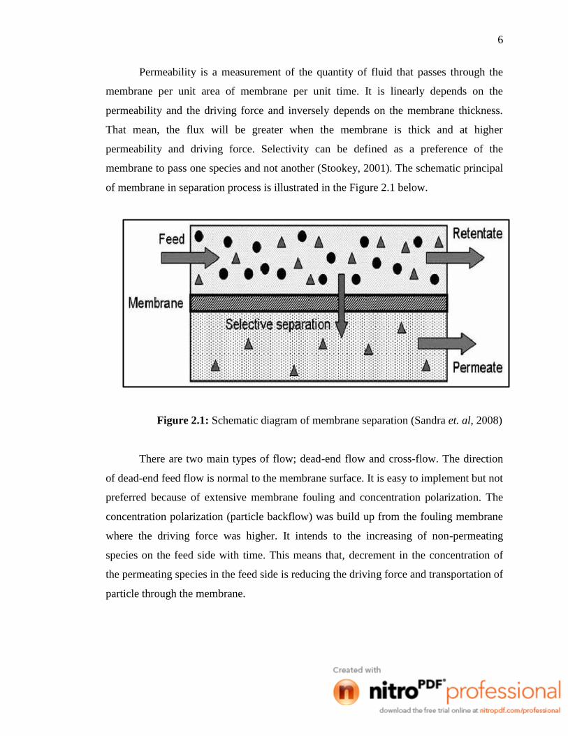
Permeability is a measurement of the quantity of fluid that passes through the
membrane per unit area of membrane per unit time. It is linearly depends on the
permeability and the driving force and inversely depends on the membrane thickness.
That mean, the flux will be greater when the membrane is thick and at higher
permeability and driving force. Selectivity can be defined as a preference of the
membrane to pass one species and not another (Stookey, 2001). The schematic principal
of membrane in separation process is illustrated in the Figure 2.1 below.
Figure 2.1: Schematic diagram of membrane separation (Sandra et. al, 2008)
There are two main types of flow; dead-end flow and cross-flow. The direction
of dead-end feed flow is normal to the membrane surface. It is easy to implement but not
preferred because of extensive membrane fouling and concentration polarization. The
concentration polarization (particle backflow) was build up from the fouling membrane
where the driving force was higher. It intends to the increasing of non-permeating
species on the feed side with time. This means that, decrement in the concentration of
the permeating species in the feed side is reducing the driving force and transportation of
particle through the membrane.

7
In contrast, the cross-flow membrane process is the preferred one due to its
tangential flow to the membrane surface. Further downstream, the retentate is removed
and on the other side, the operation which is permeating flow is tracked. There is four
cases of cross-flow operation which is co-current, counter-current, cross-flow with
perfect permeate mixing and perfect mixing operation. The types of the feed flow are
shown in the Figure 2.2 below.
Figure 2.2: Feed flow illustration
2.1.3 Types of membrane
Generally, there are two types of membrane which is biological membrane and
synthetic membrane. A biological membrane is a selective barrier layer that is around
the cell which consists of lipid bilayer with embedded protein. The lipid and protein
composition in this membrane is different due to its types.
8
In the other hand, the synthetic membrane was produced from organic or
inorganic materials. A membrane from inorganic materials such as silicon carbides,
aluminium oxides or zirconium oxides is resistant to the strong solvent action and
chemically and thermally stable. One of the popular membranes that used in the
separation industry is a polymeric membrane.
A polymeric membrane is an organic synthetic membrane that can selectively
transfer certain chemical species over others. Common polymers that commonly used in
membrane synthesis are cellulose acetates (CA), cellulose nitrates (CN), cellulose esters
(CE), polysulfone (PS), polyether sulfone(PES), polyacrilonitrile (PAN), polyamide
(PA), polyethylene (PE), polypropylene (PP), polytetrafluoroethylene (PTFE),
polyvinylidene fluoride (PVDF) and polyvinylchloride (PVC).
Another type of membrane is micro porous membrane. This type of membrane is
generally made by applying 1 to 3 thin layers to a porous support. The porous support
can be in flat sheets, disks or tubes and can be either ceramic or metallic. Meanwhile the
microporous layers are generally metal oxides and are often silica. Microporous
membrane usually applied for coal gasification, reformed natural gas and in high-
temperature electrolysis.
Homogenous dense and asymmetric membranes are also the main type of
membrane that usually used. Homogenous dense membrane usually prepared by solvent
evaporation from the solution or by extrusion of the melted polymer. This type of
membrane is practical when it is made from highly permeable polymers like silicon.
9
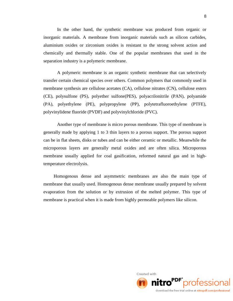
2.1.4 Membrane structure
Membranes can be classified according to their morphology. The morphology of
the membranes is illustrated on the Figure 2.3.
Figure 2.3: Membrane classification according to morphology (Nunes et al., 2001)
A dense membrane usually prepared from highly permeable polymer in a
minimal thickness in order to give the mechanical stability to the membrane. Therefore,
most of application used porous membrane or composite membrane which combines the
dense layer at the top and porous membrane at the bottom.
A symmetric membrane have a constant diameter pores and it is resistance to
mass transfer due to its thickness. In contrast, asymmetric membrane has a different pore
sizes between the top surface and the bottom one. The size difference unable the particle
to pass through the membrane and the plugging must be avoided. One best solution to
this problem is by using composite membrane. The top layer of the composite will be

10
the membrane selectivity to the porous one at the bottom. The bottom layer has high
porosity and high thickness.
2.1.5 Mechanism of membrane
Mechanism of membrane in separation process can be divided into:
i. By size
Macropores, mesopores and micropores are three terms that defined the pore
sizes in membrane for microfiltration, ultrafiltration and nanofiltration
membrane. This type of membrane is used to removed contaminants based on
sized.
ii. Different in solubility and diffuse of materials
This type of mechanism is based on the diffusion of solute and solvent. The
membrane has a small pores and only solvent passes through it by sorption-
diffusion method. A composite of homogenous film is the good example.
iii. By charge
This mechanism used in an ion exchange membrane where the same charge ion
is excluded in the same phase. It is practically used in electrolytic cell separator.
There are three types of mechanism used in the gas separation membrane;
Knudsen diffusion, molecular sieving and solution-diffusion. In Knudsen diffusion
mechanism, the component of the gas is separated according to the difference in mean
path of the gas molecules. In contrast, the gas is separated based on the diameter size of
molecule in molecular sieving mechanism. A solution-diffusion happen when permeates
dissolved in the membrane material and separation is achieved because of differences in
amount of material dissolves in the membrane and rate of material that diffuse. Figure
2.4 below shows the mechanism in gas separation.

11
Figure 2.4: Illustrations of membrane mechanism (Sandra et al., 2008)
2.2 Membrane Process
Based on previous study, Aizan et al., 2006 claimed that the membrane separation
process is characterized by several aspects. There are:
Separation goal
Nature of species retained (size of the species)
Nature of species transported through membrane, electrodylasis or volatile
Minor or major species of the feed solution transported through membrane
Driving forces
Phase of feed and permeate stream
Mechanism for transport/selectivity
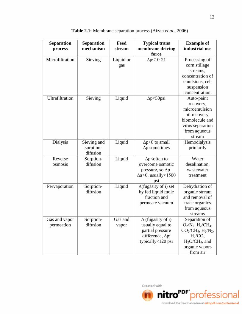
The membrane separation processes are summarized in the Table 2.1 and
characterized based on the mechanism used; feed stream, trans membrane driving force
and its application in the industry.
12
Table 2.1: Membrane separation process (Aizan et al., 2006)
Separation
process
Separation
mechanism
Feed
stream
Typical trans
membrane driving
force
Example of
industrial use
Microfiltration Sieving Liquid or
gas
∆p<10-21 Processing of
corn stillage
streams,
concentration of
emulsions, cell
suspension
concentration
Ultrafiltration Sieving Liquid ∆p<50psi Auto-paint
recovery,
microemulsion
oil recovery,
biomolecule and
virus separation
from aqueous
stream
Dialysis Sieving and
sorption-
difusion
Liquid ∆p<0 to small
∆p sometimes
Hemodialysis
primarily
Reverse
osmosis
Sorption-
difusion
Liquid ∆p<often to
overcome osmotic
pressure, so ∆p-
∆π>0, usually<1500
psi
Water
desalination,
wastewater
treatment
Pervaporation Sorption-
difusion
Liquid ∆(fugasity of i) set
by fed liquid mole
fraction and
permeate vacuum
Dehydration of
organic stream
and removal of
trace organics
from aqueous
streams
Gas and vapor
permeation
Sorption-
difusion
Gas and
vapor
∆ (fugasity of i)
usually equal to
partial pressure
difference, ∆pi
typically<120 psi
Separation of
O2/N2, H2/CH4,
CO2/CH4, H2/N2,
H2/CO,
H2O/CH4, and
organic vapors
from air
13
2.3 Membrane Module
Membrane module can be defined as the building block of the membrane and
generally its configuration can divided into two; flat and tubular.
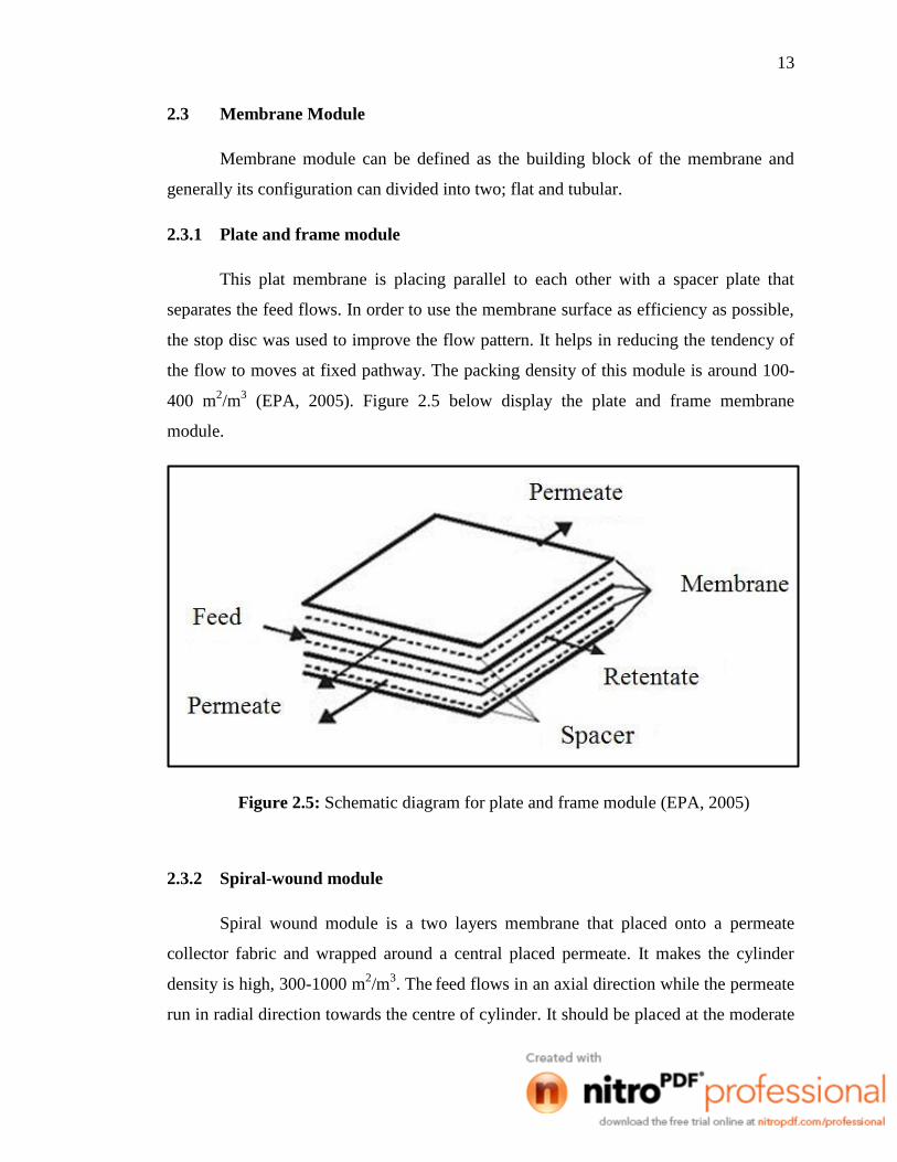
2.3.1 Plate and frame module
This plat membrane is placing parallel to each other with a spacer plate that
separates the feed flows. In order to use the membrane surface as efficiency as possible,
the stop disc was used to improve the flow pattern. It helps in reducing the tendency of
the flow to moves at fixed pathway. The packing density of this module is around 100-
400 m2/m
3 (EPA, 2005). Figure 2.5 below display the plate and frame membrane
module.
Figure 2.5: Schematic diagram for plate and frame module (EPA, 2005)
2.3.2 Spiral-wound module
Spiral wound module is a two layers membrane that placed onto a permeate
collector fabric and wrapped around a central placed permeate. It makes the cylinder
density is high, 300-1000 m2/m
3. The
feed flows in an axial direction while the permeate
run in radial direction towards the centre of cylinder. It should be placed at the moderate

14
high to prevent the plugging happen. The spiral wound membrane module shown in the
Figure 2.6.
Figure 2.6: Spiral wound membrane module (EPA, 2005)
2.3.3 Tubular Module
The supporting material is placed inside a 5 to 15 mm diameter tubular tube. Its
bigger size makes the density quite low and plugging seems not happen. The attachment
of the supporting materials is not strong enough and makes the feed flow in the centre of
the membrane tube and the permeate flow outside the tubular. Figure 2.7 shows the
module for tubular membrane.