product selector - fp mccannfpmccann.co.uk/.../files/easi-cast-product-selector-brochure.pdf ·...
TRANSCRIPT

Product Selector
www.fpmccann.co.uk
2011 Version 1
www.fpmccann.co.uk [email protected]
P1Precast ConcreteCivil Engineering Systems
FP McCann is the UK’s market leader in the manufacture, supply and delivery of precast concrete drainage products. The standard range includes a full choice of concrete flexible jointed pipes from DN 225 to DN 2400 including bends, junctions and fittings. Complementary products to complete a pipeline system, include manhole bases and chamber rings, catch-pits, headwalls and gully pots. FP McCann is a member of the Concrete Pipeline Systems Association (CPSA). Our comprehensive precast concrete business extends to include products such as shaft and tunnel segments, power cable ducting, railway components and concrete fencing posts and panels, as well as a bespoke product service to customer specification.Modern manufacturing plants at Alnwick (Northumberland), Ellistown (Leicestershire), Cadeby (Warks), Telford (Shropshire) and Knockloughrim (Northern Ireland) incorporate the latest computerised batching, distribution, casting, curing and handling systems and are operated by skilled and experienced workforces to ensure consistency of quality. Their geographical spread gives us an unrivalled ability to serve the construction industry throughout the UK and Ireland.All our operations are carried out under the auspices of our Integrated Management System, which is accredited to ISO 9001 and ISO 18001. We hold BSI kitemark accreditation and applicable products are manufactured to the relevant parts of BS EN 1916 and BS EN1917. In order to achieve the DC4 design chemical class the raw materials and manfacturing processes meet the design criteria prescribed in BRE Special Digest 1:2005 Concrete in aggressive ground; and are designed for both surface and foul water applications. It is reasonable to expect a correctly designed, installed and maintained pipe line system to achieve a service life in excess of 100 years.This product guide is intended to provide specifiers and contractors with details of the broad range of FP McCann’s precast concrete civil engineering products, including basic information on testing and laying of spigot and socket pipes. Should you require additional information, please contact our Support Team on one of the main contact numbers. The following sources may also be of assistance:
Technical information• FP McCann Easi-Base brochure• FP McCann quality section of our website at www.fpmccann.co.uk• Concrete Pipeline Systems Association (CPSA) “Complete Technical Guide”• WRc’s Sewers for Adoption• Civil Engineering Specification for Water Industry
General Information• FP McCann website: www.fpmccann.co.uk• CPSA website: www.concretepipes.co.uk• Pipe Jacking Association website: www.pipejacking.org
Accrediation• BSI 5911 Kitemark accredited• Quality Management System accredited to ISO 9001• ISO 18001 Health & Safety Management• WRc approved Easi-Base DN1200 - DN2100
FP McCannFP McCann is the trading name of F.P. McCann Limited, incorporated in Northern Ireland, number N.I. 13563.
www.fpmccann.co.uk [email protected]
P2Contents
DrainageSpigot & Socket Pipes 3-4Easi-Flex Oblique Tumbling Junction 5Easi-Flex Square Tumbling Junction 6Easi-Flex Sealing System 7Easi-Lift Pipe Lifter 8Easi-Flex Anchor System 9Easi-Slide Wall Pipes 10Easi-Slide Pipes 11Easi-Slide Handling Instructions 12Handling & Laying Instructions 13Easi-Flex Joint Gaps 14Manhole Chamber 15Manhole Soakaways 16Wide Wall Manhole Chambers 17-18DN4000 Manhole Chamber 19Recommended Site Work Practice 20Manhole Cover Sabs & Accessories 21Adjusting Units & Corbel Slabs 22Easi-Safe Fall Arrest System 23House Inspection Chambers 24Gullies & Slabs Range 25DN1200 Easi-Base (Polypropylene -lined) 26DN1200 Easi-Base Dimensions 27DN1500 - DN1800 Easi-Base (GRP & Unlined) 28FPM Tools AutoCAD Toolbar 29Easi-Pit (DN1050 Catch-Pit) 30Headwalls & Silt Traps 31Easi-Flow Chamber 32Plastic Encapsulated Ladders & Rungs 33Handhold & Entry Pole System 34Easi-Box Culverts 35-36
Water ManagementEasi-Storm Attenuation Systems 37Easi-Hydro Separator 38-39Easi-Rain Harvesting Chambers 40
Tunnels & Shafts FP McCann Tunnels & Shafts 41Smoothbore Tunnel & Shaft Segments 42-43Shaft Cover & Landing Slabs 44-45Caisson Units 46-47Jacking Pipes 48
Infrastructure & PowerPower Infrastucture Cable Ducting Systems 49-53
Railway Rail Products 54
FencingFencing Products 55
Kerbs & ChannelsKerbs & Channels Range 56
Bespoke Specialist Products 57
www.fpmccann.co.uk [email protected]
P3
Drainage
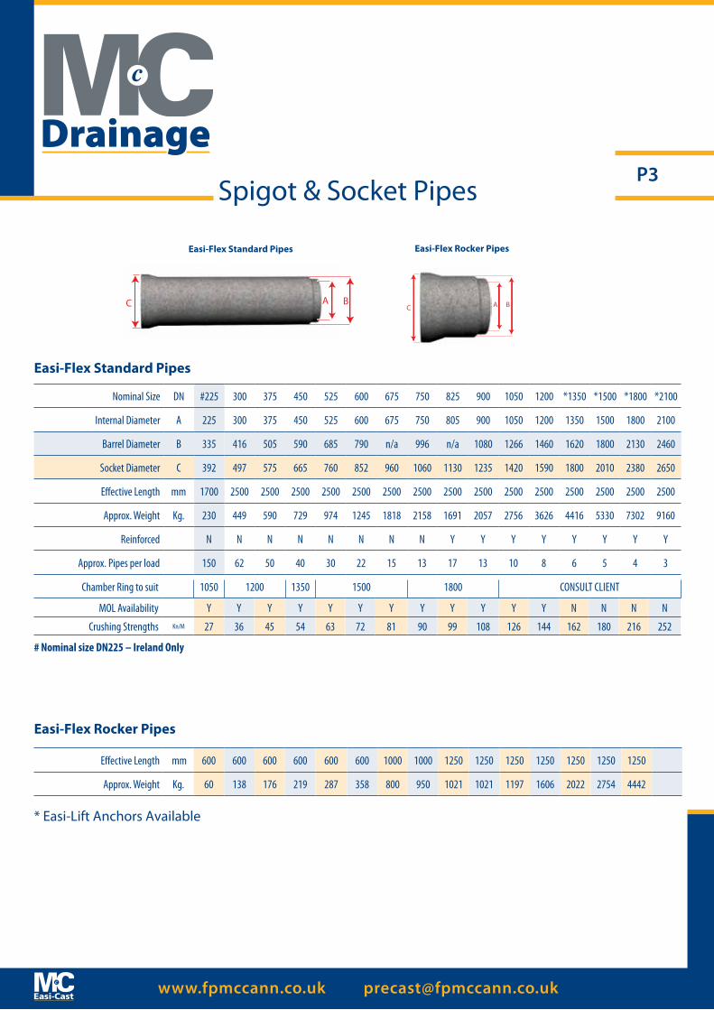
Nominal Size DN #225 300 375 450 525 600 675 750 825 900 1050 1200 *1350 *1500 *1800 *2100
Internal Diameter A 225 300 375 450 525 600 675 750 805 900 1050 1200 1350 1500 1800 2100
Barrel Diameter B 335 416 505 590 685 790 n/a 996 n/a 1080 1266 1460 1620 1800 2130 2460
Socket Diameter C 392 497 575 665 760 852 960 1060 1130 1235 1420 1590 1800 2010 2380 2650
Effective Length mm 1700 2500 2500 2500 2500 2500 2500 2500 2500 2500 2500 2500 2500 2500 2500 2500
Approx. Weight Kg. 230 449 590 729 974 1245 1818 2158 1691 2057 2756 3626 4416 5330 7302 9160
Reinforced N N N N N N N N Y Y Y Y Y Y Y Y
Approx. Pipes per load 150 62 50 40 30 22 15 13 17 13 10 8 6 5 4 3
Chamber Ring to suit 1050 1200 1350 1500 1800 CONSULT CLIENT
MOL Availability Y Y Y Y Y Y Y Y Y Y Y Y N N N N
Crushing Strengths Kn/M 27 36 45 54 63 72 81 90 99 108 126 144 162 180 216 252
Easi-Flex Standard Pipes
Easi-Flex Rocker Pipes
Spigot & Socket Pipes
* Easi-Lift Anchors Available
Easi-Flex Rocker Pipes
Easi-Flex Standard Pipes
Effective Length mm 600 600 600 600 600 600 1000 1000 1250 1250 1250 1250 1250 1250 1250
Approx. Weight Kg. 60 138 176 219 287 358 800 950 1021 1021 1197 1606 2022 2754 4442
# Nominal size DN225 – Ireland Only
C BA A B C
www.fpmccann.co.uk [email protected]
P4Spigot & Socket Pipes
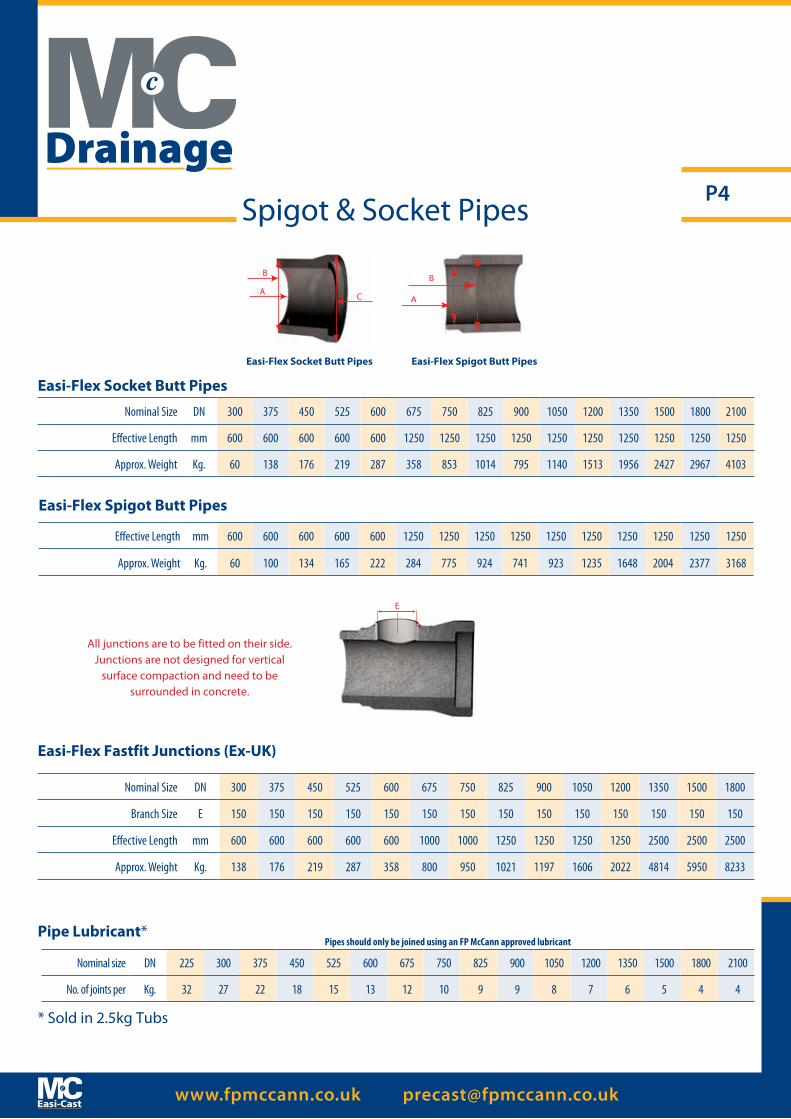
Nominal Size DN 300 375 450 525 600 675 750 825 900 1050 1200 1350 1500 1800
Branch Size E 150 150 150 150 150 150 150 150 150 150 150 150 150 150
Effective Length mm 600 600 600 600 600 1000 1000 1250 1250 1250 1250 2500 2500 2500
Approx. Weight Kg. 138 176 219 287 358 800 950 1021 1197 1606 2022 4814 5950 8233
Easi-Flex Fastfit Junctions (Ex-UK)
All junctions are to be fitted on their side. Junctions are not designed for vertical
surface compaction and need to be surrounded in concrete.
Nominal size DN 225 300 375 450 525 600 675 750 825 900 1050 1200 1350 1500 1800 2100
No. of joints per Kg. 32 27 22 18 15 13 12 10 9 9 8 7 6 5 4 4
Pipe Lubricant*Pipes should only be joined using an FP McCann approved lubricant
* Sold in 2.5kg Tubs
A
B
C
B
A
Easi-Flex Socket Butt Pipes Easi-Flex Spigot Butt Pipes
Easi-Flex Socket Butt Pipes
Nominal Size DN 300 375 450 525 600 675 750 825 900 1050 1200 1350 1500 1800 2100
Effective Length mm 600 600 600 600 600 1250 1250 1250 1250 1250 1250 1250 1250 1250 1250
Approx. Weight Kg. 60 138 176 219 287 358 853 1014 795 1140 1513 1956 2427 2967 4103
Easi-Flex Spigot Butt Pipes
Effective Length mm 600 600 600 600 600 1250 1250 1250 1250 1250 1250 1250 1250 1250 1250
Approx. Weight Kg. 60 100 134 165 222 284 775 924 741 923 1235 1648 2004 2377 3168
E
Drainage
www.fpmccann.co.uk [email protected]
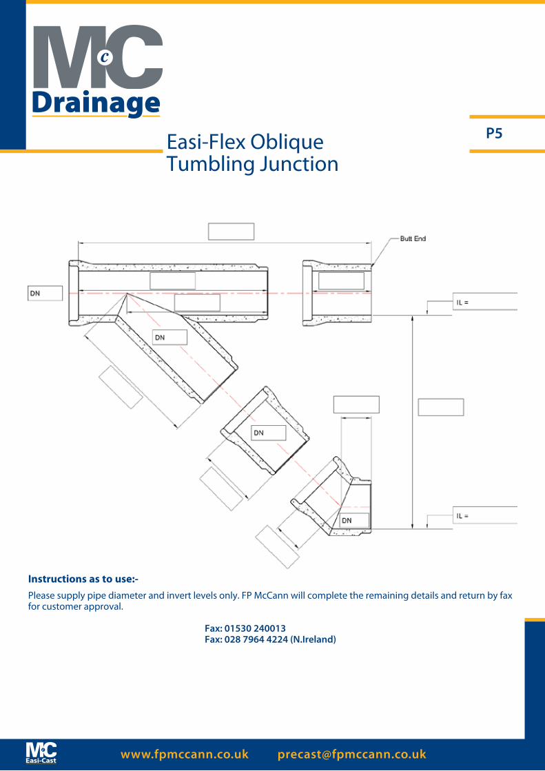
P5Easi-Flex ObliqueTumbling Junction
Drainage
Instructions as to use:-Please supply pipe diameter and invert levels only. FP McCann will complete the remaining details and return by fax for customer approval.
Fax: 01530 240013Fax: 028 7964 4224 (N.Ireland)

www.fpmccann.co.uk [email protected]
P6
All bends are manufactured
to ±4° tolerance
Easi-Flex SquareTumbling Junction
Instructions as to use:-Please supply pipe diameter and invert levels only. FP McCann will complete the remaining details and return by fax for customer approval.
Fax: 01530 240013Fax: 028 7964 4224 (N.Ireland)
Drainage
www.fpmccann.co.uk [email protected]
P7Easi-Flex Sealing System
• Cast in Seal • Self Aligning • Faster and Easier Jointing
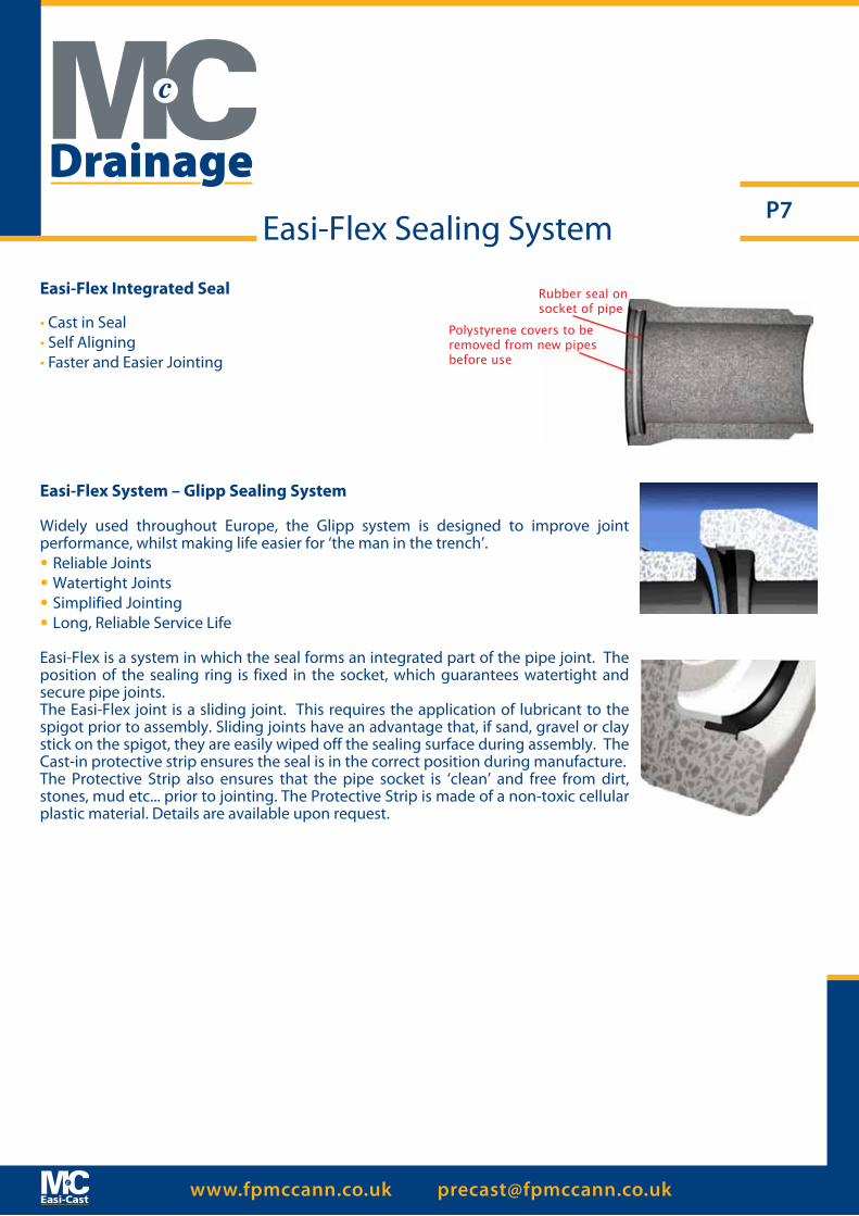
Rubber seal onsocket of pipe
Polystyrene covers to beremoved from new pipesbefore use
Easi-Flex Integrated Seal
Easi-Flex System – Glipp Sealing System
Widely used throughout Europe, the Glipp system is designed to improve joint performance, whilst making life easier for ‘the man in the trench’.• Reliable Joints• Watertight Joints• Simplified Jointing• Long, Reliable Service Life
Easi-Flex is a system in which the seal forms an integrated part of the pipe joint. The position of the sealing ring is fixed in the socket, which guarantees watertight and secure pipe joints.The Easi-Flex joint is a sliding joint. This requires the application of lubricant to the spigot prior to assembly. Sliding joints have an advantage that, if sand, gravel or clay stick on the spigot, they are easily wiped off the sealing surface during assembly. The Cast-in protective strip ensures the seal is in the correct position during manufacture.The Protective Strip also ensures that the pipe socket is ‘clean’ and free from dirt, stones, mud etc... prior to jointing. The Protective Strip is made of a non-toxic cellular plastic material. Details are available upon request.
Drainage
www.fpmccann.co.uk [email protected]
P8Easi-Lift Pipe Lifter
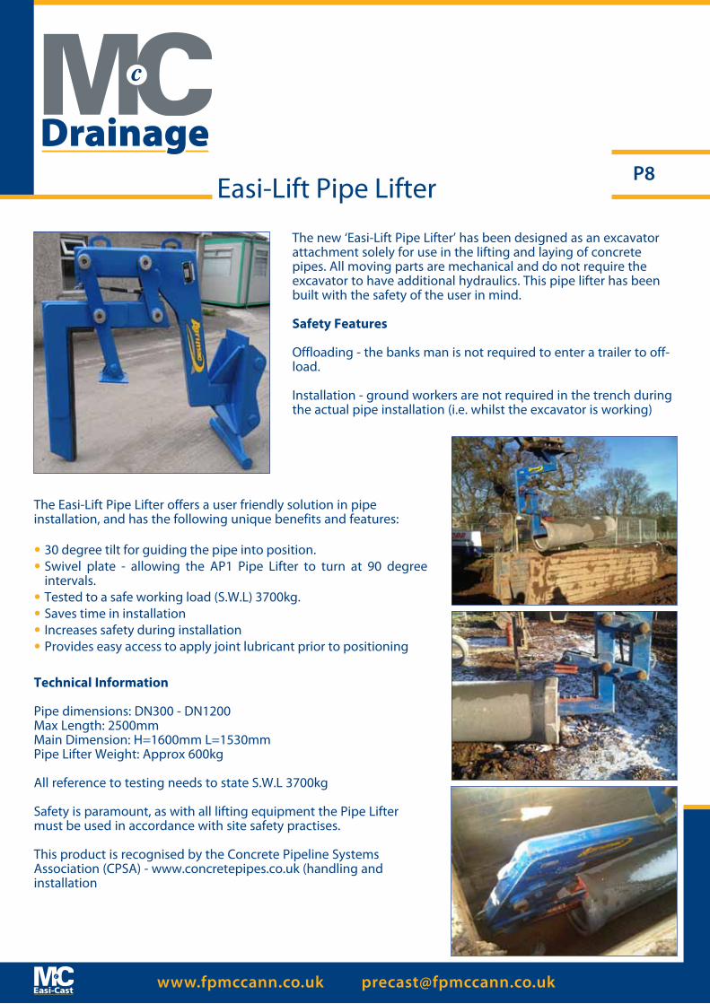
The new ‘Easi-Lift Pipe Lifter’ has been designed as an excavator attachment solely for use in the lifting and laying of concrete pipes. All moving parts are mechanical and do not require the excavator to have additional hydraulics. This pipe lifter has been built with the safety of the user in mind.
Safety Features
Offloading - the banks man is not required to enter a trailer to off-load.
Installation - ground workers are not required in the trench during the actual pipe installation (i.e. whilst the excavator is working)
The Easi-Lift Pipe Lifter offers a user friendly solution in pipe installation, and has the following unique benefits and features:
• 30 degree tilt for guiding the pipe into position.• Swivel plate - allowing the AP1 Pipe Lifter to turn at 90 degree
intervals.• Tested to a safe working load (S.W.L) 3700kg.• Saves time in installation• Increases safety during installation• Provides easy access to apply joint lubricant prior to positioning
Technical Information
Pipe dimensions: DN300 - DN1200Max Length: 2500mmMain Dimension: H=1600mm L=1530mmPipe Lifter Weight: Approx 600kg
All reference to testing needs to state S.W.L 3700kg
Safety is paramount, as with all lifting equipment the Pipe Lifter must be used in accordance with site safety practises.
This product is recognised by the Concrete Pipeline Systems Association (CPSA) - www.concretepipes.co.uk (handling and installation
Drainage
www.fpmccann.co.uk [email protected]
P9
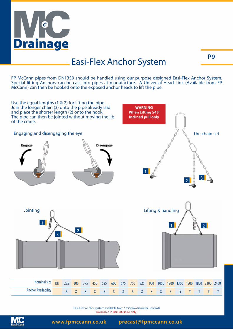
Use the equal lengths (1 & 2) for lifting the pipe.Join the longer chain (3) onto the pipe already laid and place the shorter length (2) onto the hook.The pipe can then be jointed without moving the jib of the crane.
The chain setEngaging and disengaging the eye
Lifting & handlingJointing
1
1 1
2
22
3
3
Nominal size DN 225 300 375 450 525 600 675 750 825 900 1050 1200 1350 1500 1800 2100 2400
Anchor Availability X X X X X X X X X X X X Y Y Y Y Y
Easi-Flex anchor system available from 1350mm diameter upwards(Available in DN1200 in NI only)
FP McCann pipes from DN1350 should be handled using our purpose designed Easi-Flex Anchor System. Special lifting Anchors can be cast into pipes at manufacture. A Universal Head Link (Available from FP McCann) can then be hooked onto the exposed anchor heads to lift the pipe.
WARNING When Lifting ≥45°Inclined pull only
Easi-Flex Anchor System
Drainage
www.fpmccann.co.uk [email protected]
P10
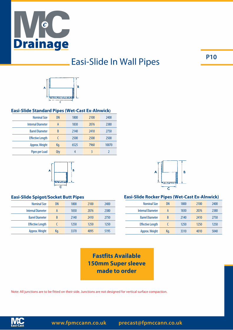
Easi-Slide Standard Pipes (Wet-Cast Ex-Alnwick) Nominal Size DN 1800 2100 2400
Internal Diameter A 1830 2076 2380
Barrel Diameter B 2140 2410 2750
Effective Length C 2500 2500 2500
Approx. Weight Kg. 6525 7960 10070
Pipes per Load Qty 4 3 2
Easi-Slide Spigot/Socket Butt PipesNominal Size DN 1800 2100 2400
Internal Diameter A 1830 2076 2380
Barrel Diameter B 2140 2410 2750
Effective Length C 1250 1250 1250
Approx. Weight Kg. 3370 4095 5195
Easi-Slide In Wall Pipes
Fastfits Available150mm Super sleeve
made to order
Easi-Slide Rocker Pipes (Wet-Cast Ex-Alnwick)Nominal Size DN 1800 2100 2400
Internal Diameter A 1830 2076 2380
Barrel Diameter B 2140 2410 2750
Effective Length C 1250 1250 1250
Approx. Weight Kg. 3310 4010 5040
Note: All junctions are to be fitted on their side. Junctions are not designed for vertical surface compaction.
Drainage
www.fpmccann.co.uk [email protected]
P11
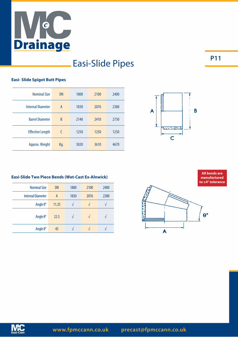
Easi-Slide Two Piece Bends (Wet-Cast Ex-Alnwick)
Nominal Size DN 1800 2100 2400
Internal Diameter A 1830 2076 2380
Angle θ° 11.25 √ √ √
Angle θ° 22.5 √ √ √
Angle θ° 45 √ √ √
Easi-Slide Pipes
Easi- Slide Spigot Butt Pipes
Nominal Size DN 1800 2100 2400
Internal Diameter A 1830 2076 2380
Barrel Diameter B 2140 2410 2750
Effective Length C 1250 1250 1250
Approx. Weight Kg. 3020 3610 4670
All bends are manufactured
to ±4° tolerance
Drainage
www.fpmccann.co.uk [email protected]
P12
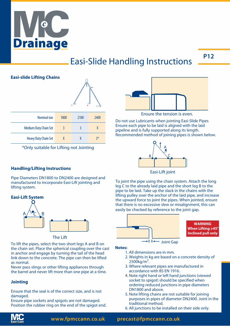
Handling/Lifting Instructions
Pipe Diameters DN1800 to DN2400 are designed and manufactured to incorporate Easi-Lift jointing and lifting system.
Easi-Lift System
To lift the pipes, select the two short legs A and B on the chain set. Place the spherical coupling over the cast in anchor and engage by turning the tail of the head link down to the concrete. The pipe can then be lifted as normal.Never pass slings or other lifting appliances through the barrel and never lift more than one pipe at a time.
Jointing
Ensure that the seal is of the correct size, and is not damaged.Ensure pipe sockets and spigots are not damaged. Position the rubber ring on the end of the spigot end.
Do not use Lubricants when jointing Easi-Slide PipesEnsure each pipe to be laid is aligned with the laid pipeline and is fully supported along its length.Recommended method of joining pipes is shown below.
To joint the pipe using the chain system. Attach the long leg C to the already laid pipe and the short leg B to the pipe to be laid. Take up the slack in the chains with the lifting pulley over the anchor of the laid pipe, and increase the upward force to joint the pipes. When jointed, ensure that there is no excessive slew or misalignment, this can easily be checked by reference to the joint gap.
Notes:1. All dimensions are in mm.2. Weights in kg are based on a concrete density of
2500kg/m³.3. Where relevant pipes are manufactured in accordance with BS EN 1916.4. Note right hand or left hand junctions (viewed
socket to spigot) should be specified when ordering reduced junctions in pipe diameters DN1800 and above.
5. Note lifting chains are not suitable for joining purposes in pipes of diameter DN2400. Joint in the traditional method.
6. All junctions to be installed on their side only.
The Lift
Ensure the tension is even.
Easi-Lift joint
Easi-Slide Handling Instructions
A BC
Joint Gap
A
B C
WARNING When Lifting ≥45°Inclined pull only
Nominal size 1800 2100 2400
Medium Duty Chain Set 3 3 X
Heavy Duty Chain Set X X 3*
Easi-slide Lifting Chains
A B C
*Only suitable for Lifting not Jointing
Drainage
www.fpmccann.co.uk [email protected]
P13Handling & Laying Instructions
Recommended Site Work Practice – Open Cut Flexible Jointed Pipes
Handling & Storing Pipes1. Time and place of off-loading should be agreed before the units arrive at site. The contractor should provide suitable equipment for off-loading, stacking and
stringing out of pipes on site.2. Off-loading should take place at the nearest hard road to the point of installation. To ensure the safety of all personnel, units must be left in a stable position
well clear of the edge of the trench.3. Pipes should be inspected before off-loading to ensure that materials delivered correspond to order placed.4. Pipes should be carefully checked during off-loading to ensure no units are damaged. Any discrepancies should be
recorded on the delivery docket.5. Where stacking is necessary, this should be done on level ground and the bottom layer of pipes securely chocked to
prevent the stack from collapsing. Pipes should be supported under the barrel so that the socket is free of load so that the jointing faces are not damaged. They should preferably be stacked barrel to barrel with sockets hanging over alternative sides.
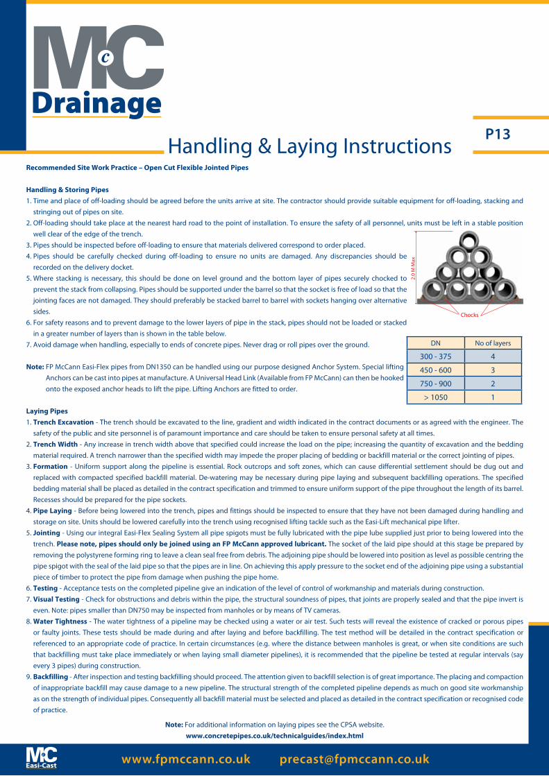
6. For safety reasons and to prevent damage to the lower layers of pipe in the stack, pipes should not be loaded or stacked in a greater number of layers than is shown in the table below.
7. Avoid damage when handling, especially to ends of concrete pipes. Never drag or roll pipes over the ground.
Note: FP McCann Easi-Flex pipes from DN1350 can be handled using our purpose designed Anchor System. Special lifting Anchors can be cast into pipes at manufacture. A Universal Head Link (Available from FP McCann) can then be hooked onto the exposed anchor heads to lift the pipe. Lifting Anchors are fitted to order.
Laying Pipes1. Trench Excavation - The trench should be excavated to the line, gradient and width indicated in the contract documents or as agreed with the engineer. The
safety of the public and site personnel is of paramount importance and care should be taken to ensure personal safety at all times.2. Trench Width - Any increase in trench width above that specified could increase the load on the pipe; increasing the quantity of excavation and the bedding
material required. A trench narrower than the specified width may impede the proper placing of bedding or backfill material or the correct jointing of pipes.3. Formation - Uniform support along the pipeline is essential. Rock outcrops and soft zones, which can cause differential settlement should be dug out and
replaced with compacted specified backfill material. De-watering may be necessary during pipe laying and subsequent backfilling operations. The specified bedding material shall be placed as detailed in the contract specification and trimmed to ensure uniform support of the pipe throughout the length of its barrel. Recesses should be prepared for the pipe sockets.
4. Pipe Laying - Before being lowered into the trench, pipes and fittings should be inspected to ensure that they have not been damaged during handling and storage on site. Units should be lowered carefully into the trench using recognised lifting tackle such as the Easi-Lift mechanical pipe lifter.
5. Jointing - Using our integral Easi-Flex Sealing System all pipe spigots must be fully lubricated with the pipe lube supplied just prior to being lowered into the trench. Please note, pipes should only be joined using an FP McCann approved lubricant. The socket of the laid pipe should at this stage be prepared by removing the polystyrene forming ring to leave a clean seal free from debris. The adjoining pipe should be lowered into position as level as possible centring the pipe spigot with the seal of the laid pipe so that the pipes are in line. On achieving this apply pressure to the socket end of the adjoining pipe using a substantial piece of timber to protect the pipe from damage when pushing the pipe home.
6. Testing - Acceptance tests on the completed pipeline give an indication of the level of control of workmanship and materials during construction.7. Visual Testing - Check for obstructions and debris within the pipe, the structural soundness of pipes, that joints are properly sealed and that the pipe invert is
even. Note: pipes smaller than DN750 may be inspected from manholes or by means of TV cameras.8. Water Tightness - The water tightness of a pipeline may be checked using a water or air test. Such tests will reveal the existence of cracked or porous pipes
or faulty joints. These tests should be made during and after laying and before backfilling. The test method will be detailed in the contract specification or referenced to an appropriate code of practice. In certain circumstances (e.g. where the distance between manholes is great, or when site conditions are such that backfilling must take place immediately or when laying small diameter pipelines), it is recommended that the pipeline be tested at regular intervals (say every 3 pipes) during construction.
9. Backfilling - After inspection and testing backfilling should proceed. The attention given to backfill selection is of great importance. The placing and compaction of inappropriate backfill may cause damage to a new pipeline. The structural strength of the completed pipeline depends as much on good site workmanship as on the strength of individual pipes. Consequently all backfill material must be selected and placed as detailed in the contract specification or recognised code of practice.
Note: For additional information on laying pipes see the CPSA website.www.concretepipes.co.uk/technicalguides/index.html
2.0
M M
ax
Chocks
DN No of layers
300 - 375 4
450 - 600 3
750 - 900 2
> 1050 1
Drainage
www.fpmccann.co.uk [email protected]
P14
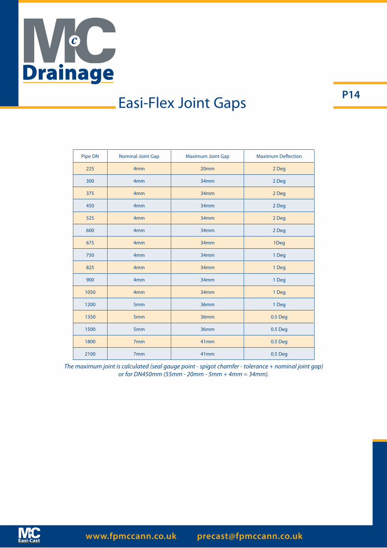
Pipe DN Nominal Joint Gap Maximum Joint Gap Maximum Deflection
225 4mm 20mm 2 Deg
300 4mm 34mm 2 Deg
375 4mm 34mm 2 Deg
450 4mm 34mm 2 Deg
525 4mm 34mm 2 Deg
600 4mm 34mm 2 Deg
675 4mm 34mm 1Deg
750 4mm 34mm 1 Deg
825 4mm 34mm 1 Deg
900 4mm 34mm 1 Deg
1050 4mm 34mm 1 Deg
1200 5mm 36mm 1 Deg
1350 5mm 36mm 0.5 Deg
1500 5mm 36mm 0.5 Deg
1800 7mm 41mm 0.5 Deg
2100 7mm 41mm 0.5 Deg
The maximum joint is calculated (seal gauge point - spigot chamfer - tolerance + nominal joint gap) or for DN450mm (55mm - 20mm - 5mm + 4mm = 34mm).
Easi-Flex Joint Gaps
Drainage

www.fpmccann.co.uk [email protected]
P15
Manhole Chambers (Tongue & Groove Joint)
A
D
B
Nominal Size (DN) 1000mm 750mm 500mm 250mm
Wall Thickness
mm
litres/meters
Barrel Diameter
mm
Approx Weight
Kg. (p/meter)
Approx. Productsper load
Qty.(meter)
Lifting HoleQty/dia(p/Unit)
900 √ √ √ √ 70 656 1040 520 38 3x45mm dia
1050 √ √ √ √ 80 894 1210 690 34 3x45mm dia
1200 √ √ √ √ 90 1167 1380 880 26 3x45mm dia
1350 √ √ √ 95 1478 1540 1050 22 3x45mm dia
1500 √ √ √ 105# 1824 1710 1300 16 3x45mm dia
1800 √ √ √ 115 2544 2030 1750 12 3x45mm dia
2100 √ √ √ 125 3464 2350 2040 10 4x50mm dia
2400 √ √ √ 140 4514 2680 2790 8 4x50mm dia
2700 √ √ √ 150 5725 3000 3370 8 4x50mm dia
*3000 Alnwick √ √ √ 180 7069 3360 3850 6 4x50mm dia
*3000 Telford √ √ √ 210 7069 3420 5050 5 4x50mm dia
**3600 √ √ √ 185 10179 3970 5400 5 4x50mm dia
**4000 √ √ 200 12566 4400 6800 1.5 6x50mm dia
Dia ± 5mm
Available Depth of Section
Tongue and Groove Joint Profile
Product Information # Ellistown as per table above, DN 1500 Manhole Rings Ex-Knockloughrim have a wall thickness of 95mm and a Barrell diameter of
1690mm.* DN 3000 - Please Note wall thickness details between Telford and Alnwick product. ** DN 3600 and DN 4000 are not covered by the British Standard (Non-Kitemark), but comply with all relevant provisions of the European
Standard. DN 4000 is supplied in two halves (see seperate jointing instructions).
• Manhole chambers ex-Ellistown from DN1800 - DN4000 have 4 lifting points. Manholes less than DN1800 have 3 lifting points.• Manhole chambers ex-Knockloughrim from DN3000 - DN4000 have 4 lifting points. Manholes less than DN3000 have 3 lifting points.
Manhole Chambers
WARNING When Lifting ≥45°Inclined pull only
MOL from 900-2700 Upon Request
Drainage
www.fpmccann.co.uk [email protected]
P16
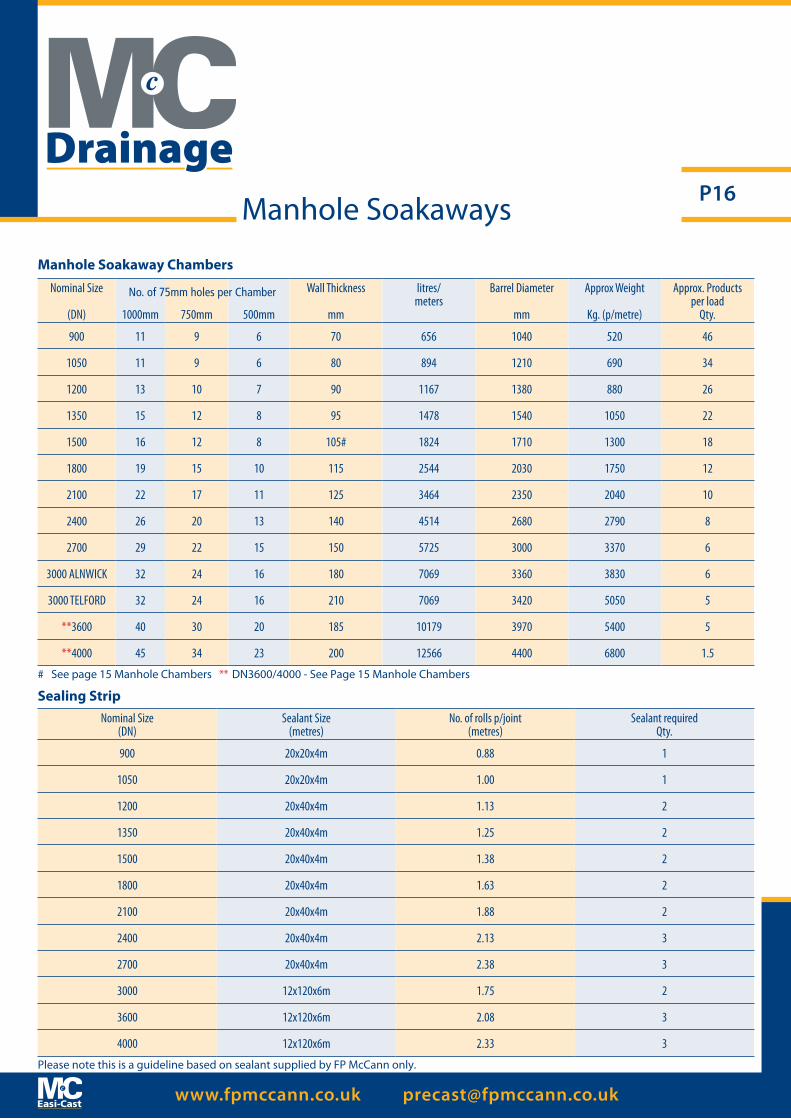
Nominal Size(DN)
Sealant Size(metres)
No. of rolls p/joint(metres)
Sealant requiredQty.
900 20x20x4m 0.88 1
1050 20x20x4m 1.00 1
1200 20x40x4m 1.13 2
1350 20x40x4m 1.25 2
1500 20x40x4m 1.38 2
1800 20x40x4m 1.63 2
2100 20x40x4m 1.88 2
2400 20x40x4m 2.13 3
2700 20x40x4m 2.38 3
3000 12x120x6m 1.75 2
3600 12x120x6m 2.08 3
4000 12x120x6m 2.33 3
Sealing Strip
Please note this is a guideline based on sealant supplied by FP McCann only.
Nominal Size
(DN) 1000mm 750mm 500mm
Wall Thickness
mm
litres/meters
Barrel Diameter
mm
Approx Weight
Kg. (p/metre)
Approx. Productsper load
Qty.
900 11 9 6 70 656 1040 520 46
1050 11 9 6 80 894 1210 690 34
1200 13 10 7 90 1167 1380 880 26
1350 15 12 8 95 1478 1540 1050 22
1500 16 12 8 105# 1824 1710 1300 18
1800 19 15 10 115 2544 2030 1750 12
2100 22 17 11 125 3464 2350 2040 10
2400 26 20 13 140 4514 2680 2790 8
2700 29 22 15 150 5725 3000 3370 6
3000 ALNWICK 32 24 16 180 7069 3360 3830 6
3000 TELFORD 32 24 16 210 7069 3420 5050 5
**3600 40 30 20 185 10179 3970 5400 5
**4000 45 34 23 200 12566 4400 6800 1.5
Manhole Soakaway Chambers
No. of 75mm holes per Chamber
Manhole Soakaways
# See page 15 Manhole Chambers ** DN3600/4000 - See Page 15 Manhole Chambers
Drainage

www.fpmccann.co.uk [email protected]
P17
DN 1200mm Wide Wall Manhole Chamber A 130mm thick wide wall chamber in combination with the Easi Base unit, provides a sealed watertight manhole system. This robust design means that the requirement for a concrete surround is eliminated.
Advantages• Speedy and easy installation• Watertight on construction• Lifting loops built into wall• Safer lifting system (spherical head lifting system)• Cost saving - No back fill with concrete
Wide Wall Manhole Chambers
Nominal Size (DN) 1000mm 750mm 500mm 250mm
Wall Thickness
mm
Barrel Diameter
mm
Approx Weight
Kg. (p/meter)
Approx. Productsper load
Qty.(meter)
DEHA Lifting AnchorsQty/dia
1200 √ √ √ √ 130 1460 1520 16 3x45mm dia
Available Depth of Section
F P McCann wide wall manholes have been designed with a tongue and groove dimension to accommodate the use of bituminous sealant. An F P McCann approved sealant should be used at all times. The sealant requirement for wide wall manholes is 12mm x 120mm x 6m. When placing sealing strip into position during installation, the ends of the strips must be overlapped by a minimum of 30mm and cut at an angle of 60 degree. The cut ends must then be pressed together. Full installation guidelines can be provided upon request or can be found at www.fpmccann.co.uk
Drainage
* DN 1500 & 1800 in development

www.fpmccann.co.uk [email protected]
P18
Nominal Size (DN) 1000mm 750mm 500mm 250mm
Wall Thickness
mm
Barrel Diameter
mm
Approx Weight
Kg. (p/meter)
Approx. Productsper load
Qty.(meter)
Lifting PointQty/dia(p/Unit)
36mm Lifting Pin 0.75 t SWL
42mm Lifting Pin 3.5 t SWL
3 leg Lifting Chain SWL
3.1t
4 leg Lifting Chain SWL
6.7 t
1200 √ √ √ √ 130 1460 1520 16 3x45mm dia
Lifting clutches. F P McCann supply
recommended and approved lifting clutches.
√
Available Depth of Section
Wide Wall Manhole Chambers
Drainage
www.fpmccann.co.uk [email protected]
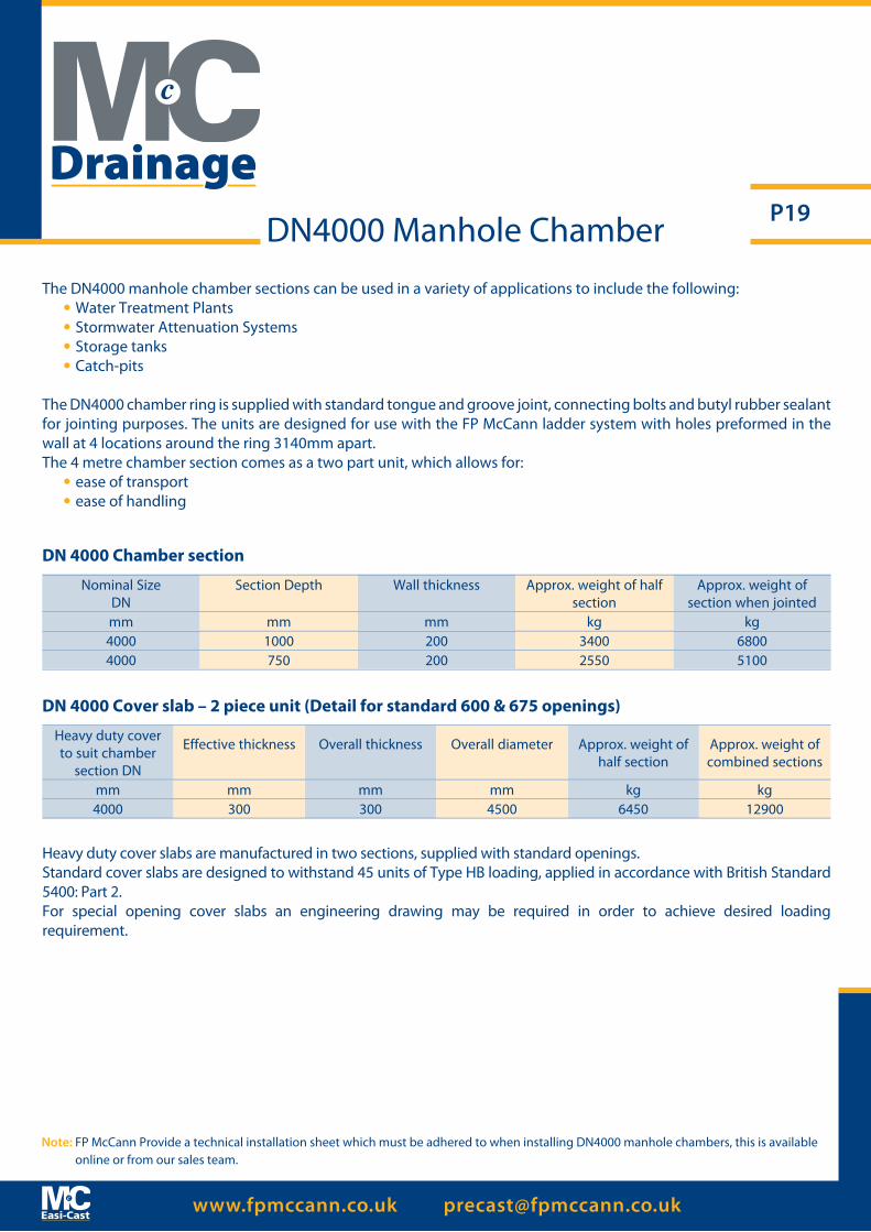
P19DN4000 Manhole ChamberThe DN4000 manhole chamber sections can be used in a variety of applications to include the following:
• Water Treatment Plants• Stormwater Attenuation Systems• Storage tanks• Catch-pits
The DN4000 chamber ring is supplied with standard tongue and groove joint, connecting bolts and butyl rubber sealant for jointing purposes. The units are designed for use with the FP McCann ladder system with holes preformed in the wall at 4 locations around the ring 3140mm apart. The 4 metre chamber section comes as a two part unit, which allows for:
• ease of transport• ease of handling
DN 4000 Chamber section
Nominal SizeDN
Section Depth Wall thickness Approx. weight of half section
Approx. weight of section when jointed
mm mm mm kg kg4000 1000 200 3400 68004000 750 200 2550 5100
DN 4000 Cover slab – 2 piece unit (Detail for standard 600 & 675 openings)
Heavy duty cover to suit chamber
section DN
Effective thickness Overall thickness Overall diameter Approx. weight of half section
Approx. weight of combined sections
mm mm mm mm kg kg4000 300 300 4500 6450 12900
Heavy duty cover slabs are manufactured in two sections, supplied with standard openings.Standard cover slabs are designed to withstand 45 units of Type HB loading, applied in accordance with British Standard 5400: Part 2. For special opening cover slabs an engineering drawing may be required in order to achieve desired loading requirement.
Note: FP McCann Provide a technical installation sheet which must be adhered to when installing DN4000 manhole chambers, this is available online or from our sales team.
Drainage
www.fpmccann.co.uk [email protected]
P20
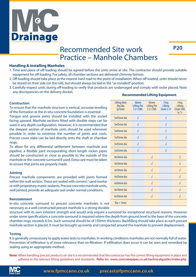
Handling & Installing Manholes1. Time and place of off-loading should be agreed before the units arrive at site. The contractor should provide suitable
equipment for off-loading. For safety, all chamber sections are delivered chimney fashion.2. Off-loading should take place at the nearest hard road to the point of installation. When off-loaded, units should never
be stored on their side (on the roll), but should always be laid in the “as installed” position.3. Carefully inspect units during off-loading to verify that products are undamaged and comply with order placed. Note
any discrepancies on the delivery docket.
Recommended Site work Practice – Manhole Chambers
ConstructionTo ensure that the manhole structure is vertical, accurate levelling of the formation or the in-situ concrete foundation is essential.Tongue and groove joints should be installed with the socket facing upward. Manhole sections fitted with double steps can be used in any depth configuration. However, it is recommended that the deepest section of manhole units should be used whenever possible in order to minimise the number of joints and costs. Precast cover slabs can be laid directly onto the shaft or chamber rings.To allow for any differential settlement between manhole and pipeline, a flexible joint incorporating short length rocker pipes should be constructed as close as possible to the outside of the manhole or the concrete surround if used. Extra care must be taken to ensure that joints are properly made.
JointingPrecast manhole components are provided with joints formed within the wall section. These are sealed with cement / sand mortar or with proprietary mastic sealants. Precast concrete manhole units, well jointed, provide an adequate seal under normal conditions.
ReinstatementIn-situ concrete surround to precast concrete manholes is not necessary as a well constructed precast manhole is a strong durable structure with its own inherent strength and would only require a surround for exceptional structural reasons. However under some specifications a concrete surround is required where the depth from ground level to the base of the concrete chamber rings, exceeds 4.5m. Such surround should be of 150mm thickness. Backfilling should take place as each precast manhole section is placed. It must be brought up evenly and compacted around the manhole to prevent displacement.
TestingIt is generally unnecessary to apply water tests to manholes. In working conditions manholes are not normally full of water.Prevention of infiltration is of more relevance than ex-filtration. If infiltration does occur it can be seen and remedied by sealing using an appropriate method.
Note: When handling precast products on site it is recommended that the contractor has the correct lifting equipment in place and adheres to the relevant lifting guidelines and standards. Refer to:- www.concretepipes.co.uk/technicalguides/index.php
Recommended Lifting Equipment
Lifting HoleQty/dia(p/Unit)
36mmLifting Pin3.5 t SWL
42mmLifting Pin3.5 t SWL
3 leg Lifting
Chain 3.1t
4 leg Lifting
Chain SWL 6.7 t
3x45mm dia √ √
3x45mm dia √ √
3x45mm dia √ √
3x45mm dia √ √
3x45mm dia √ √
3x45mm dia √ √
4x50mm dia √ √
4x50mm dia √ √
4x50mm dia √ √
4x50mm dia √ √
4x50mm dia √ √
4x50mm dia √ √
6x50mm dia √ √
Dia + 5mm
Drainage

www.fpmccann.co.uk [email protected]
P21
C
B A
Cover Slabs
STANDARD COVER SLABS STANDARD REDUCING SLABSShaft or Chamber Nominal
Size DN (mm)Outside Diameter
(A) Slab Thickness (C)Opening Configuration B Approximate Weight
(KG)Opening Diameter B
(mm)Effective Depth
(mm)Approximate Weight
(KG)Size (mm) Location
900 1060 150 600x600 CENTRAL 215675x675
1050 1230 150600x600
ECCENTRIC315675x675
750x750 CENTRAL
1200 1400 150600x600
ECCENTRIC 455 900 250 385675x675750x600
1350 1570 162
600x600ECCENTRIC
6501050 250 695
675x675750x600
1200 250 5501200x675 CENTRAL
1500 1740 187
600x600ECCENTRIC
980900
10501200
250250250
981835680
675x675750x600
1200x675 CENTRAL
1800 2060 187
600x600
ECCENTRIC 1460900
10501200
250250250
149513501220
675x675750x600
1200x675
2100 2380 192
600x600
ECCENTRIC 2180900
10501200
250250250
213026902540
675x675750x600
1200x675
2400 2710 192
600x600
ECCENTRIC 2800900
10501200
250250250
281526902540
675x675750x600
1200x675
2700 3030 217
600x600
ECCENTRIC 3750900
10501200
250250250
369535503410
675x675750x600
1200x675
3000 ALNWICK 3330 213
600x600
ECCENTRIC 4760900
10501200
250250250
476047604760
675x675750x600
1200x675
3000 TELFORD 3420 200
600x600
ECCENTRIC 4970900
10501200
250250250
497049704970
675x675750x600
1200x675
*3600 4000 300
600x600
ECCENTRIC 9100675x675750x600
1200x675
4000 4500 300
600x600
ECCENTRIC 12900675x675750x600
1200x675
Reducing SlabsA
B
C
Manhole Cover Slabs & Accessories
Chamber Section (DN) Outside Diameter (A) Opening Diameter (B) Slab Thickness (C) Approx. Weight (Kg.)
1500 1730 900 175 826
1800 2050 900 175 1292
2100 2375 900 180 2030
2400 2705 900 180 2600
2700 3025 900 205 3880
3000 3330 900 213 4500
Landing Slabs
B
A
C
MULTIPLE ACCESS/OTHER ACCESS SIZED COVER SLABS CAN BE MADE TO ORDER
Covers to suit Manholes greater than or equal to 1.5m deep cover level to pipe soffit.
* 3600mm and 4000mm diameter cover slabs come in a 2 piece unit
Drainage
www.fpmccann.co.uk [email protected]
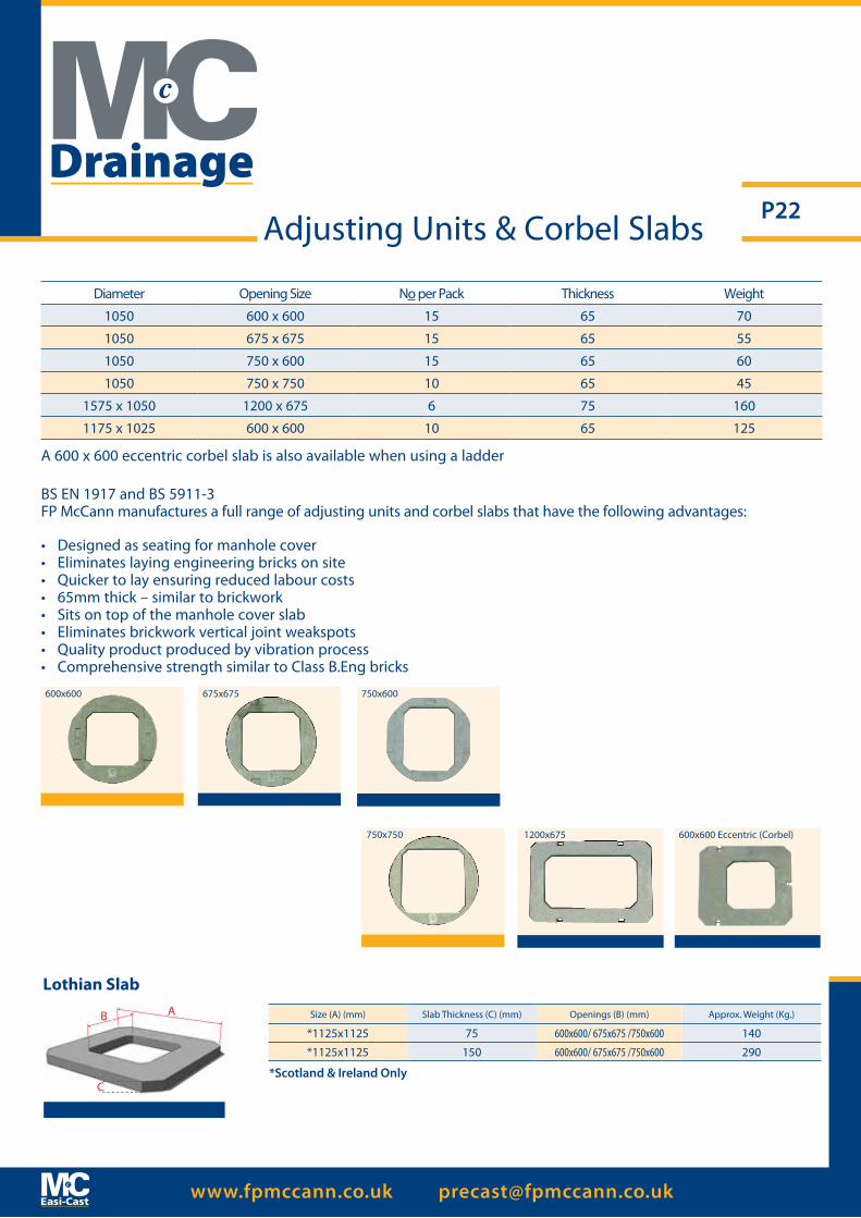
P22Adjusting Units & Corbel Slabs
Size (A) (mm) Slab Thickness (C) (mm) Openings (B) (mm) Approx. Weight (Kg.)
*1125x1125 75 600x600/ 675x675 /750x600 140
*1125x1125 150 600x600/ 675x675 /750x600 290
Lothian Slab
B A
C
BS EN 1917 and BS 5911-3FP McCann manufactures a full range of adjusting units and corbel slabs that have the following advantages:
A 600 x 600 eccentric corbel slab is also available when using a ladder
• Designed as seating for manhole cover• Eliminates laying engineering bricks on site• Quicker to lay ensuring reduced labour costs• 65mm thick – similar to brickwork• Sits on top of the manhole cover slab• Eliminates brickwork vertical joint weakspots• Quality product produced by vibration process• Comprehensive strength similar to Class B.Eng bricks
600x600 675x675 750x600
750x750 1200x675 600x600 Eccentric (Corbel)
*Scotland & Ireland Only
Diameter Opening Size No per Pack Thickness Weight
1050 600 x 600 15 65 70
1050 675 x 675 15 65 55
1050 750 x 600 15 65 60
1050 750 x 750 10 65 45
1575 x 1050 1200 x 675 6 75 160
1175 x 1025 600 x 600 10 65 125
Drainage

www.fpmccann.co.uk [email protected]
P23Easi-Safe Fall Arrest System
Award Winning Safety Solution For Manhole Construction
The client, consultant engineer, contractors and suppliers all have a duty to mitigate hazards on site whenever reasonably practicable.One such hazard identified is the risk of operatives falling through manhole openings particularly during the construction process and also in follow up maintenance work.Working with partners Severn Trent Water, engineer Grontmij and contractor to the water sector, Morgan Sindall plc, FP McCann have designed a safety award winning solution. Easi-Safe is a temporary or permanent fall arrest system that allows for safe working around the manhole opening prior to the fitting of the ironwork. In the construction of a manhole, operatives often work unprotected from the opening at surface level when the final stages of completion occur. This includes the final brickwork up to the manhole frame and the mortar bedding of the frame itself.
With most standard cover slabs, the access point for man entry is open and it is left to the contractor to cover on site. In many site situations these openings remain for a number of days while gangs complete phases of work. Easi-Safe immediately addresses this problem. The future production of all standard access cover slabs will incorporate the optional protective grid which will remain in the slab even when the final D400 steel cover and frame are set in place at surface level.
The galvanised mild steel grid is available in four standard sizes:-• 610mm x 610mm• 675mm x 675mm• 750mm x 600mm• 1200mm x 675mm
The Easi-Safe grid is seated on load bearing corners precast into a standard range of manhole cover slabs. As a temporary fall arrest system, once the construction of the manhole is complete, the grid can be removed prior to the fitting of the ironwork. Alternatively, Easi-Safe can be a permanent fixture, left in place beneath the manhole lid. The spacing between the bars allows for ease of inspection and jetting of the manhole base during maintenance work.
UNPROTECTED
Drainage
www.fpmccann.co.uk [email protected]
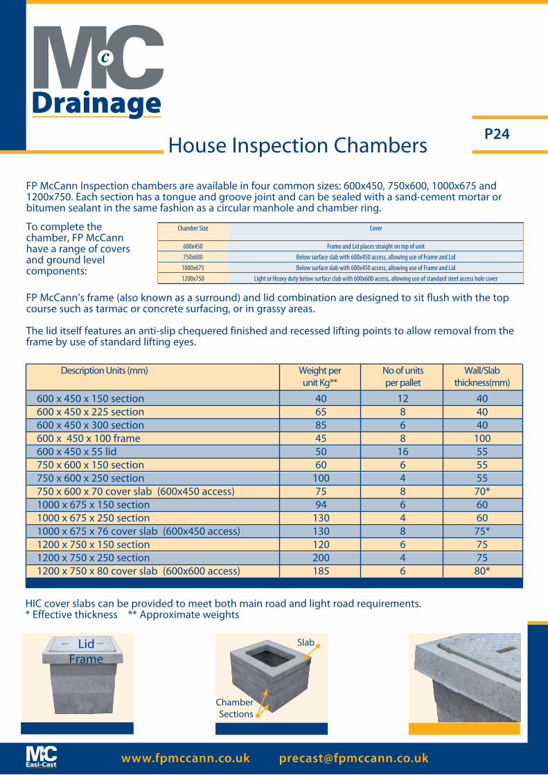
P24House Inspection Chambers
FP McCann Inspection chambers are available in four common sizes: 600x450, 750x600, 1000x675 and 1200x750. Each section has a tongue and groove joint and can be sealed with a sand-cement mortar or bitumen sealant in the same fashion as a circular manhole and chamber ring.
HIC cover slabs can be provided to meet both main road and light road requirements.* Effective thickness ** Approximate weights
Description Units (mm) Weight per No of units Wall/Slab unit Kg** per pallet thickness(mm)
600 x 450 x 150 section 40 12 40 600 x 450 x 225 section 65 8 40 600 x 450 x 300 section 85 6 40 600 x 450 x 100 frame 45 8 100 600 x 450 x 55 lid 50 16 55 750 x 600 x 150 section 60 6 55 750 x 600 x 250 section 100 4 55 750 x 600 x 70 cover slab (600x450 access) 75 8 70* 1000 x 675 x 150 section 94 6 60 1000 x 675 x 250 section 130 4 60 1000 x 675 x 76 cover slab (600x450 access) 130 8 75* 1200 x 750 x 150 section 120 6 75 1200 x 750 x 250 section 200 4 75 1200 x 750 x 80 cover slab (600x600 access) 185 6 80*
Chamber Size Cover
600x450 Frame and Lid places straight on top of unit750x600 Below surface slab with 600x450 access, allowing use of Frame and Lid
1000x675 Below surface slab with 600x450 access, allowing use of Frame and Lid1200x750 Light or Heavy duty below surface clab with 600x600 access, allowing use of standard steel access hole cover
FP McCann’s frame (also known as a surround) and lid combination are designed to sit flush with the top course such as tarmac or concrete surfacing, or in grassy areas.
The lid itself features an anti-slip chequered finished and recessed lifting points to allow removal from the frame by use of standard lifting eyes.
To complete the chamber, FP McCann have a range of covers and ground level components:
Drainage
ChamberSections
Slab
www.fpmccann.co.uk [email protected]
P25
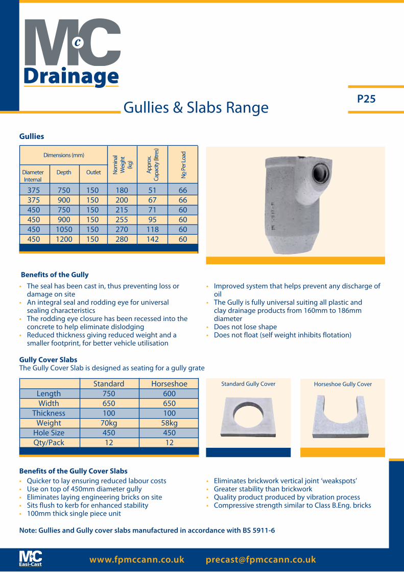
Gullies
Gully Cover Slabs The Gully Cover Slab is designed as seating for a gully grate
Benefits of the Gully• The seal has been cast in, thus preventing loss or
damage on site• An integral seal and rodding eye for universal sealing characteristics• The rodding eye closure has been recessed into the
concrete to help eliminate dislodging• Reduced thickness giving reduced weight and a
smaller footprint, for better vehicle utilisation
• Improved system that helps prevent any discharge of oil
• The Gully is fully universal suiting all plastic and clay drainage products from 160mm to 186mm diameter
• Does not lose shape• Does not float (self weight inhibits flotation)
• Quicker to lay ensuring reduced labour costs• Use on top of 450mm diameter gully• Eliminates laying engineering bricks on site• Sits flush to kerb for enhanced stability• 100mm thick single piece unit
• Eliminates brickwork vertical joint ‘weakspots’• Greater stability than brickwork• Quality product produced by vibration process• Compressive strength similar to Class B.Eng. bricks
375 750 150 180 51 66 375 900 150 200 67 66 450 750 150 215 71 60 450 900 150 255 95 60 450 1050 150 270 118 60 450 1200 150 280 142 60
Diameter Depth Outlet Internal
Nom
inal
W
eigh
t(k
g)
Appr
ox.
Capa
city (
litre
s)
No P
er Lo
adDimensions (mm)
Standard Horseshoe Length 750 600 Width 650 650 Thickness 100 100 Weight 70kg 58kg Hole Size 450 450 Qty/Pack 12 12
Standard Gully Cover Horseshoe Gully Cover
Benefits of the Gully Cover Slabs
Gullies & Slabs Range
Drainage
Note: Gullies and Gully cover slabs manufactured in accordance with BS 5911-6
www.fpmccann.co.uk [email protected]
P26
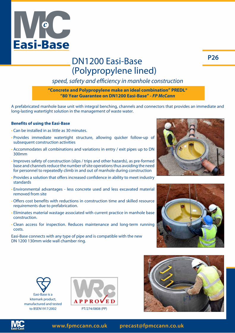
“Concrete and Polypropylene make an ideal combination” PREDL®“80 Year Guarantee on DN1200 Easi-Base” - FP McCann
A prefabricated manhole base unit with integral benching, channels and connectors that provides an immediate and long-lasting watertight solution in the management of waste water.
Benefits of using the Easi-Base
• Can be installed in as little as 30 minutes.
• Provides immediate watertight structure, allowing quicker follow-up of subsequent construction activities
• Accommodates all combinations and variations in entry / exit pipes up to DN 300mm
• Improves safety of construction (slips / trips and other hazards), as pre-formed base and channels reduce the number of site operations thus avoiding the need for personnel to repeatedly climb in and out of manhole during construction
• Provides a solution that offers increased confidence in ability to meet industry standards
• Environmental advantages - less concrete used and less excavated material removed from site
• Offers cost benefits with reductions in construction time and skilled resource requirements due to prefabrication.
• Eliminates material wastage associated with current practice in manhole base construction.
• Clean access for inspection. Reduces maintenance and long-term running costs.
Easi-Base connects with any type of pipe and is compatible with the new DN 1200 130mm wide wall chamber ring.
DN1200 Easi-Base (Polypropylene lined)
Easi-Base is a kitemark product,
manufactured and testedto BSEN1917:2002 PT/274/0808 (PP)
speed, safety and efficiency in manhole construction
www.fpmccann.co.uk [email protected]
P27
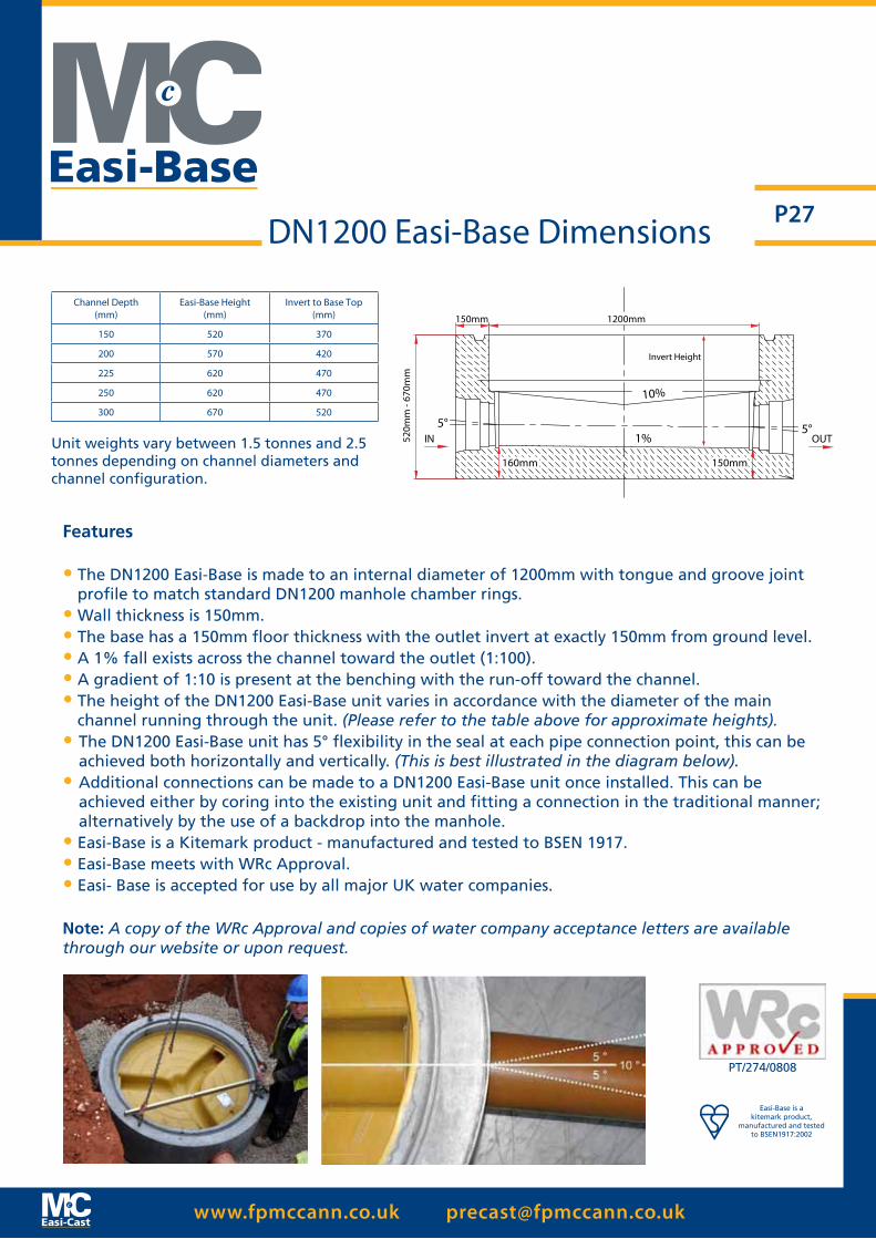
Features
• The DN1200 Easi-Base is made to an internal diameter of 1200mm with tongue and groove joint profile to match standard DN1200 manhole chamber rings.
• Wall thickness is 150mm.• The base has a 150mm floor thickness with the outlet invert at exactly 150mm from ground level.• A 1% fall exists across the channel toward the outlet (1:100).• A gradient of 1:10 is present at the benching with the run-off toward the channel.• The height of the DN1200 Easi-Base unit varies in accordance with the diameter of the main
channel running through the unit. (Please refer to the table above for approximate heights).• The DN1200 Easi-Base unit has 5° flexibility in the seal at each pipe connection point, this can be
achieved both horizontally and vertically. (This is best illustrated in the diagram below).• Additional connections can be made to a DN1200 Easi-Base unit once installed. This can be
achieved either by coring into the existing unit and fitting a connection in the traditional manner; alternatively by the use of a backdrop into the manhole.
• Easi-Base is a Kitemark product - manufactured and tested to BSEN 1917.• Easi-Base meets with WRc Approval.• Easi- Base is accepted for use by all major UK water companies.
Note: A copy of the WRc Approval and copies of water company acceptance letters are available through our website or upon request.
DN1200 Easi-Base Dimensions
Easi-Base is a kitemark product,
manufactured and testedto BSEN1917:2002
PT/274/0808
Channel Depth (mm)
Easi-Base Height(mm)
Invert to Base Top(mm)
150 520 370
200 570 420
225 620 470
250 620 470
300 670 520
Invert Height
520m
m -
670m
m
1200mm150mm
160mm 150mm
5°IN OUT
5°
10%
1%Unit weights vary between 1.5 tonnes and 2.5 tonnes depending on channel diameters and channel configuration.
www.fpmccann.co.uk [email protected]
P28DN1500 - DN1800Easi-Base (GRP & Unlined)
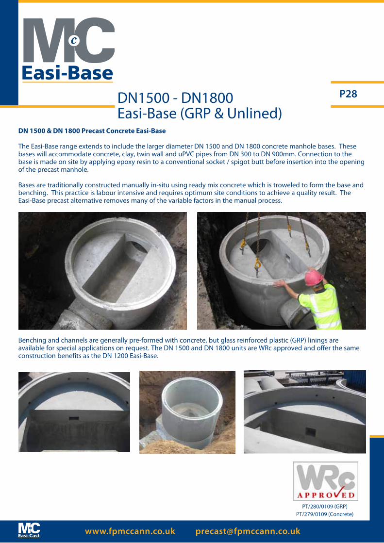
DN 1500 & DN 1800 Precast Concrete Easi-Base
The Easi-Base range extends to include the larger diameter DN 1500 and DN 1800 concrete manhole bases. These bases will accommodate concrete, clay, twin wall and uPVC pipes from DN 300 to DN 900mm. Connection to the base is made on site by applying epoxy resin to a conventional socket / spigot butt before insertion into the opening of the precast manhole.
Bases are traditionally constructed manually in-situ using ready mix concrete which is troweled to form the base and benching. This practice is labour intensive and requires optimum site conditions to achieve a quality result. The Easi-Base precast alternative removes many of the variable factors in the manual process.
PT/280/0109 (GRP)PT/279/0109 (Concrete)
Benching and channels are generally pre-formed with concrete, but glass reinforced plastic (GRP) linings are available for special applications on request. The DN 1500 and DN 1800 units are WRc approved and offer the same construction benefits as the DN 1200 Easi-Base.
www.fpmccann.co.uk [email protected]
P29
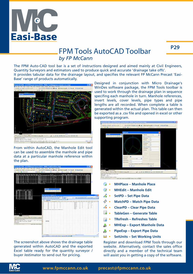
The FPM Auto-CAD tool bar is a set of instructions designed and aimed mainly at Civil Engineers, Quantity Surveyors and estimators used to produce quick and accurate ‘drainage take offs’.It provides tabular data for the drainage layout, and specifies the relevant FP McCann Precast ‘Easi-Base’ range of products automatically.
Designed in conjunction with Micro Drainage's WinDes software package, the FPM Tools toolbar is used to work through the drainage plan in sequence specifing each manhole in turn. Manhole references, invert levels, cover levels, pipe types and pipe lengths are all recorded. When complete a table is generated within the actual plan. This table can then be exported as a .csv file and opened in excel or other supporting program.
FPM Tools AutoCAD Toolbarby FP McCann
From within AutoCAD, the Manhole Edit tool can be used to assemble the manhole and pipe data at a particular manhole reference within the plan.
The screenshot above shows the drainage table generated within AutoCAD and the exported Excel table ready for the quantity surveyor / buyer /estimator to send out for pricing.
• MHPlace – Manhole Place
• MHEdit – Manhole Edit
• SetPD – Set Pipe Data
• MatchPD – Match Pipe Data
• ClearPD – Clear Pipe Data
• TableGen – Generate Table
• TRefresh – Refreshes Table
• MHExp – Export Manhole Data
• PipeExp – Export Pipe Data
• SetUnits – Set Working Units
Register and download FPM Tools through our website. Alternatively, contact the sales office directly and a member of the technical team will assist you in getting a copy of the software.

www.fpmccann.co.uk [email protected]
P30
Pipes should only be connected to the Easi-Pit using an FP McCann approved lubricant
Easi-Pit (DN 1050 Catch-pit)
DN 1050 Precast CatchpitThe DN1050 catchpit effectively provides a sealed sump manhole, a monolithic precast concrete unit fitted with connector seals which can be used to connect to the following types of pipe: uPVC, twinwall, clay, ductile iron and concrete. The catchpit is designed to accommodate pipe sizes DN150 to DN450. The catchpit is designed in line with highway specification.FP McCann can produce catchpits upto DN375 in a straight through orientation (180 degrees). 4-way units with orientations at 90 degrees can be produced upto DN300 only; beyond DN300 4-way orientations are not available. DN450 inlets must be cored onsite.
Benefits of using the DN1050 catchpit unit• Creates an immediate watertight structure• Cost benefits with reduction in construction time and resource requirement• Economically advantageous as limited wet trades are required in the manhole
construction• Accommodates connection to all types of pipe used in road and manhole
construction• Safety benefits gained in the construction of manholes as the pre-formed sump
and connector seals eliminate on site construction, thus greatly reducing labour activity within the manhole
• Increased confidence to meet industry standards• Quality is greatly increased as construction is within the factory environment• Eliminates material wastage associated with current in-situ method• Yields environmental benefits with less concrete used on site and less excavated
material removed from site
Easi-Pit weight 1.38tonnes.
DN1050 Catchpit Dimensions
Easi-Base is a kitemark product,
manufactured and testedto BSEN1917:2002
Note: Standard unit will have an invert level of 300mm for inlet and outlet pipes. If a non-standard invert level is required, please specify when ordering.
WARNING When Lifting ≥45°Inclined pull only
DN150mm - DN450mm
Drain Hole (80mm O.D.)to accommodate 65mm nominal bore pipe
Invert Level 300mm
DN45mm (x3)
Drainage
www.fpmccann.co.uk [email protected]
P31
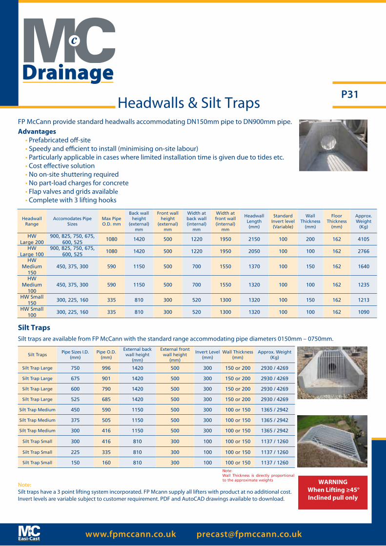
Note: Silt traps have a 3 point lifting system incorporated. FP Mcann supply all lifters with product at no additional cost. Invert levels are variable subject to customer requirement. PDF and AutoCAD drawings available to download.
Headwall Range
Accomodates Pipe Sizes
Max Pipe O.D. mm
Back wall height
(external) mm
Front wall height
(external) mm
Width at back wall (internal)
mm
Width at front wall (internal)
mm
Headwall Length (mm)
Standard Invert level (Variable)
Wall Thickness
(mm)
Floor Thickness
(mm)
Approx. Weight
(Kg)
HWLarge 200
900, 825, 750, 675, 600, 525
1080 1420 500 1220 1950 2150 100 200 162 4105
HWLarge 100
900, 825, 750, 675, 600, 525
1080 1420 500 1220 1950 2050 100 100 162 2766
HWMedium
150450, 375, 300 590 1150 500 700 1550 1370 100 150 162 1640
HWMedium
100450, 375, 300 590 1150 500 700 1550 1320 100 100 162 1235
HW Small 150
300, 225, 160 335 810 300 520 1300 1320 100 150 162 1213
HW Small 100
300, 225, 160 335 810 300 520 1300 1320 100 100 162 1090
Silt TrapsPipe Sizes I.D.
(mm)Pipe O.D.
(mm)
External back wall height
(mm)
External front wall height
(mm)
Invert Level(mm)
Wall Thickness(mm)
Approx. Weight (Kg)
Silt Trap Large 750 996 1420 500 300 150 or 200 2930 / 4269
Silt Trap Large 675 901 1420 500 300 150 or 200 2930 / 4269
Silt Trap Large 600 790 1420 500 300 150 or 200 2930 / 4269
Silt Trap Large 525 685 1420 500 300 150 or 200 2930 / 4269
Silt Trap Medium 450 590 1150 500 300 100 or 150 1365 / 2942
Silt Trap Medium 375 505 1150 500 300 100 or 150 1365 / 2942
Silt Trap Medium 300 416 1150 500 300 100 or 150 1365 / 2942
Silt Trap Small 300 416 810 300 100 100 or 150 1137 / 1260
Silt Trap Small 225 335 810 300 100 100 or 150 1137 / 1260
Silt Trap Small 150 160 810 300 100 100 or 150 1137 / 1260
Silt Traps
FP McCann provide standard headwalls accommodating DN150mm pipe to DN900mm pipe.Advantages
• Prefabricated off-site• Speedy and efficient to install (minimising on-site labour)• Particularly applicable in cases where limited installation time is given due to tides etc.• Cost effective solution• No on-site shuttering required• No part-load charges for concrete• Flap valves and grids available• Complete with 3 lifting hooks
Silt traps are available from FP McCann with the standard range accommodating pipe diameters 0150mm – 0750mm.
Headwalls & Silt Traps
Note:Wall Thickness is directly proportional to the approximate weights WARNING
When Lifting ≥45°Inclined pull only
Drainage
www.fpmccann.co.uk [email protected]
P32Easi-Flow Chamber
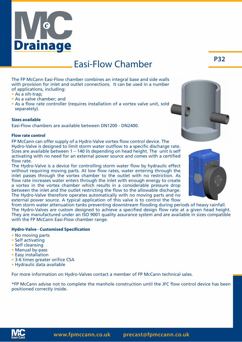
The FP McCann Easi-Flow chamber combines an integral base and side walls with provision for inlet and outlet connections. It can be used in a number of applications, including:• As a silt-trap;• As a valve chamber; and• As a flow rate controller (requires installation of a vortex valve unit, sold
separately).
Sizes availableEasi-Flow chambers are available between DN1200 - DN2400.
Flow rate controlFP McCann can offer supply of a Hydro-Valve vortex flow control device. The Hydro-Valve is designed to limit storm water outflow to a specific discharge rate. Sizes are available between 1 – 140 l/s depending on head height. The unit is self activating with no need for an external power source and comes with a certified flow rate.The Hydro-Valve is a device for controlling storm water flow by hydraulic effect without requiring moving parts. At low flow rates, water entering through the inlet passes through the vortex chamber to the outlet with no restriction. As flow rate increases water enters through the inlet with enough energy to create a vortex in the vortex chamber which results in a considerable pressure drop between the inlet and the outlet restricting the flow to the allowable discharge. The Hydro-Valve therefore operates automatically with no moving parts and no external power source. A typical application of this valve is to control the flow from storm water attenuation tanks preventing downstream flooding during periods of heavy rainfall.The Hydro-Valves are custom designed to achieve a specified design flow rate at a given head height. They are manufactured under an ISO 9001 quality assurance system and are available in sizes compatible with the FP McCann Easi-Flow chamber range.
Hydro-Valve - Customised Specification• No moving parts• Self activating• Self cleansing• Manual by-pass• Easy installation• 3-6 times greater orifice CSA• Hydraulic data available
For more information on Hydro-Valves contact a member of FP McCann technical sales.
*FP McCann advise not to complete the manhole construction until the JFC flow control device has been positioned correctly inside.
Drainage

www.fpmccann.co.uk [email protected]
P33
SummaryA system that gives the user benefits of a durable plastic encapsulated ladder without the need to specify an exact length or fit on site. In addition a single specification can be used for all depths of access.
Product SpecificationsBSEN 13101 Plastic Encapsulated StepsWIS 4-33-01: 1990 Polypropylene Encapsulated Steps
ApplicationsConcrete manholes and inspection chambers.Renovation of existing structures.
Materials High Impact Virgin Polypropylene copolymer plastic, yellow as high standard colour. If the ladder is to be subject to prolonged exposure to daylight then black or uv stabilised material should be specified. Structural steel reinforcement as standard.
PerformancePull out load: 7.5kN minimum when fitted in accordance with manufacturers instructions.Deflection under load: 5mm maximum at 2.5kNPermanent Set: 0 mm at 2.5kNImpact: 20kg weight from 1metre, no cracking.Chemical Resistance: At least pH2 to 12Integrity of plastic: 2M ohm at 500 volts DCThickness of plastic: 3mm minimumMinimum cross section: 25mm diameter
Advantages1. Excellent Corrosion Resistance2. Visibility3. No Sharp Edges4. Eliminates need to specify exact length or fit on site.5. Steel reinforcement gives predictable deflection under load without
causing brittle failure.
Plastic EncapsulatedLadders & Rungs
Drainage
www.fpmccann.co.uk [email protected]
P34
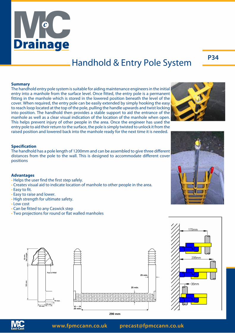
SummaryThe handhold entry pole system is suitable for aiding maintenance engineers in the initial entry into a manhole from the surface level. Once fitted, the entry pole is a permanent fitting in the manhole which is stored in the lowered position beneath the level of the cover. When required, the entry pole can be easily extended by simply hooking the easy to reach loop located at the top of the pole, pulling the handle upwards and twist locking into position. The handhold then provides a stable support to aid the entrance of the manhole as well as a clear visual indication of the location of the manhole when open. This helps prevent injury of other people in the area. Once the engineer has used the entry pole to aid their return to the surface, the pole is simply twisted to unlock it from the raised position and lowered back into the manhole ready for the next time it is needed.
SpecificationThe handhold has a pole length of 1200mm and can be assembled to give three different distances from the pole to the wall. This is designed to accommodate different cover positions
Advantages• Helps the user find the first step safely.• Creates visual aid to indicate location of manhole to other people in the area.• Easy to fit.• Easy to raise and lower.• High strength for ultimate safety.• Low cost• Can be fitted to any Caswick step• Two projections for round or flat walled manholes
290 mm
25 min.
25 min.
25 min.
20 min.25 min.
10 max.
125
mm
50 m
in.
Tail
Len
gth
Face of Wall
Handhold & Entry Pole System
Drainage

www.fpmccann.co.uk [email protected]
P35
FP McCann manufacture box culvert sections to customer specifications. By taking an individual approach to each job, we ensure that each unit supplied is engineered to the exact design criteria.
Based centrally at our Telford factory, we can deliver throughout the UK.
Culverts have a variety of different applications from the routing of water courses to providing safe pedestrian and animal crossings under road and rail infrastructure.
Uses include:
• Attenuation and Storage Tanks• Water Course Diversion• Open Channels• Road Crossings• Pedestrian, Animal and Agricultural Subways• Shafts• Conveyor Protection• Service Tunnels and Ducts
End walls, access points, vent holes, inlets, outlets, rungs, angles and splayed ends can all be added to any run of culvert. Starter bars and sockets can also be included for further casting on site.
Easi-Box Micro Micro culverts are very small, reinforced rectangular sections with internal dimensions below 0.5 of a metre, useful for water and cabling infrastructure.
They do not require deep trenches and perform with a minimal amount of cover compared to traditional circular pipes and can be utilised where there is minimal space on site. Micro culverts work above or below existing services.
Easi-Box Culverts
Drainage
www.fpmccann.co.uk [email protected]
P36Easi - Box Culverts
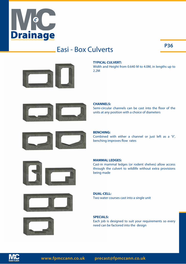
TYPICAL CULVERT:Width and Height from 0.640 M to 4.0M, in lengths up to 2.2M
CHANNELS:Semi-circular channels can be cast into the floor of the units at any position with a choice of diameters
BENCHING:Combined with either a channel or just left as a ‘V’, benching improves flow rates
MAMMAL LEDGES:Cast-in mammal ledges (or rodent shelves) allow access through the culvert to wildlife without extra provisions being made
DUAL-CELL:Two water courses cast into a single unit
SPECIALS:Each job is designed to suit your requirements so every need can be factored into the design
Drainage
www.fpmccann.co.uk [email protected]
P37
The production of water impermeable surfaces in construction is inevitable. This includes roof areas on buildings, car parks, loading bays and road pavements. The provisions of these surfaces interrupts the natural drainage process, creating increased stormwater runoff in respect of both volume and flow rate.
In many cases this increase in stormwater flow and volume is a problem as the local sewer or watercourse does not have the sufficient capacity to cope. This problem could be alleviated by an increase in the size of the stormwater sewer or watercourse, thus providing the capacity within the drainage system to cope with the increased surface water. This however may be expensive, cause major infrastructure disruption, and may often be completely unfeasible.
Legislation under Planning Policy Statement 25 and Building Regulations approved Document H3 for flood risk assessment (SUDS), has created the need for planners and developers to design and install effective storm water management systems.
The types of system that can be employed to overcome these issues are well documented and varied. Quite often, they can be very technically demanding in their operation, maintenance and construction. The selection of a system will depend on site constraints, position, expected loading, geographical limitations and inevitably cost.
The Easi-Storm system offers a complete solution to the stormwater attenuation problem and utilises a tried, tested and approved method of stormwater storage. F P McCann can provide the complete package of design, product specification, supply of products, and advice with installation.
Features:· Available in a range of sizes
· Can use and combine a number of techniques and products such as pipes, culverts, tanks, manifold systems and soakaways
· A complete solution with all connections
· Established and familiar products
· Can be laid in short lengths
· The system can be adapted to load bearing and non-load bearing applications
· 120 year design life
· Adoptable by water companies
· Manufactured in accordance with a BSI accredited quality management system conforming to BS EN ISO 9001
· Available straight from stock
Benefits:· System can be designed specifically to suit the application
· Speedy construction using a standard joint
· No need for fabrication on site or external specialist contractors
· Straightforward installation using known techniques – no need to retrain
Easi - Storm Attenuation Systems
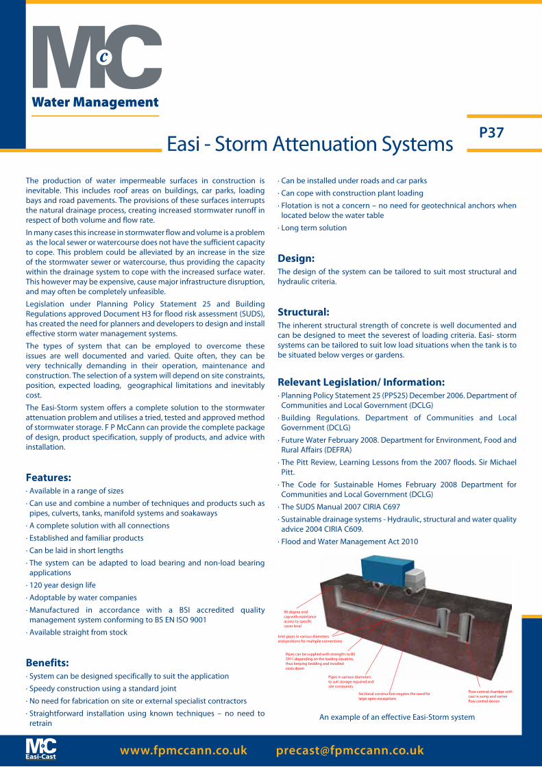
90 degree endcap with maintanceaccess to specificcover level
Inlet pipes in various diameters and positions for multipile connections
Pipes can be supplied with strengths to BS 5911 depending on the loading situation, thus keeping bedding and installed costs down
Pipes in various diameters to suit storage required and site constraints
Sectional construction negates the need for large open excavations
Flow control chamber with cast in sump and vortex flow control device
Water Management
· Can be installed under roads and car parks
· Can cope with construction plant loading
· Flotation is not a concern – no need for geotechnical anchors when located below the water table
· Long term solution
Design:The design of the system can be tailored to suit most structural and hydraulic criteria.
Structural:The inherent structural strength of concrete is well documented and can be designed to meet the severest of loading criteria. Easi- storm systems can be tailored to suit low load situations when the tank is to be situated below verges or gardens.
Relevant Legislation/ Information:· Planning Policy Statement 25 (PPS25) December 2006. Department of
Communities and Local Government (DCLG)
· Building Regulations. Department of Communities and Local Government (DCLG)
· Future Water February 2008. Department for Environment, Food and Rural Affairs (DEFRA)
· The Pitt Review, Learning Lessons from the 2007 floods. Sir Michael Pitt.
· The Code for Sustainable Homes February 2008 Department for Communities and Local Government (DCLG)
· The SUDS Manual 2007 CIRIA C697
· Sustainable drainage systems - Hydraulic, structural and water quality advice 2004 CIRIA C609.
· Flood and Water Management Act 2010
An example of an effective Easi-Storm system

www.fpmccann.co.uk [email protected]
P38
Water Management
Introduction
FP McCann have designed and developed a new range Hydrodynamic Separators for the treatment of urban catchment storm-water runoff¬. The Easi-Hydro Separator provides a cost effective solution for designers, engineers and contractors involved in the provision of sustainable urban drainage systems. The Easi-Hydro Separator has no moving parts, requires no power and is constructed in precast reinforced concrete. All internal components are manufactured in GRP and stainless steel ensuring long asset life.
The Easi-Hydro Separator has been independently tested by WRc and total solids removal rates range from 85 to 92% have been measured. The Easi-Hydro Separator is also effective in the removal of hydrocarbons, litter and other storm-water debris.
Operation
The Easi-Hydro Separator is specifically designed to remove suspended solids, hydrocarbons and floatable debris from the storm-water runoff. The Easi-Hydro Separator chamber is constructed in pre-cast reinforced concrete and supplied complete with a unique, factory installed, GRP flow management module. This unique design produces low energy vortex flow patterns allowing the solids to settle to the bottom of the treatment chamber for subsequent removal. Re-suspension of the solids is minimised by provision of a GRP baffle plate positioned above the solids storage sump. Floatable debris is retained within the Easi- Hydro Separator and prevented from discharging by a dip outlet pipe and launder channel arrangement.
Flows to treatment are controlled by a specially designed launder channel and inlet pipe arrangement. Flows in excess of the maximum treatment flow overflow a weir, bypass the treatment zone and directly discharge through the outlet pipe. This helps to minimize the effects of scour within the treatment compartment and optimises the performance of the unique Easi-Hydro Separator.
Easi-Hydro Separator
Easi-Hydro Separator

www.fpmccann.co.uk [email protected]
P39
Water Management
Easi-Hydro Separator
Applications
• Housing developments• Retail parks• Commercial centres• Leisure facilities• Industrial developments• Highway drainage projects • Car parks• Existing surface water sewer discharges• Sustainable Urban Drainage Schemes
Selection Chart
Part Number PRE EHS/1050 PRE EHS/1200 PRE EHS/1500 PRE EHS/1800 PRE EHS/2100
Chamber Diameter (mm)
1050 1200 1500 1800 2100
Treatment Flow Rate (l/sec)
15 25 35 50 75
Maximum Flow Rate (l/sec)
25 35 50 100 150
Inlet Pipe Diameter (mm)
≤225 ≤300 ≤375 ≤450 ≤525
Outlet Pipe Diameter (mm)
≤225 ≤300 ≤375 ≤450 ≤525
Sediment Storage Sump (m3)
0.75 0.85 2.50 3.00 3.2
Inletoutlet
WRc test results are available on request.

www.fpmccann.co.uk [email protected]
P40Easi-Rain Harvesting Chambers
Easi-Rain by FP McCann is a bespoke range of precast water storage chambers that are compatible with water harvesting systems for residential, industrial / commercial and agricultural installations. Capturing rainwater for re-use offers significant cost savings for the user and benefits the environment by increasing water resources and further enhancing water amenity. Easi-Rain complies with Environment Agency SUDS (Sustainable Urban Drainage System) directives.
The basic concept of harvesting rainwater is simple - rainwater is mostly collected from the roofs of buildings - it flows by gravity through gutters and downspouts and is then filtered and collected by a storage tank. From the tank it can be recirculated or treated to produce a better quality of recycled water.
Internal Diameter (x1000mm) Litres Weight
kgDN1800 1200 1800DN1800 1500 1900DN2400 3000 5900DN2400 5000 7250DN2400 7000 8700
Volume Capacity of Storage Chambers
Water Management
www.fpmccann.co.uk [email protected]
P41
Tunnels & Shafts
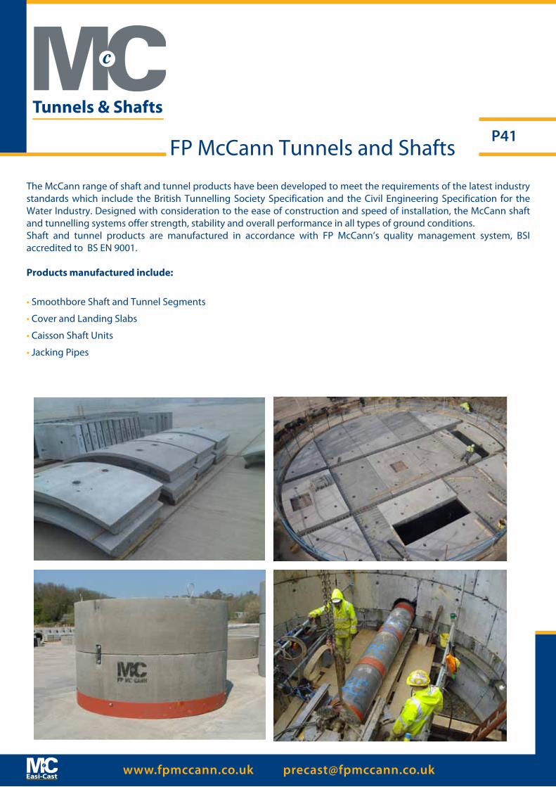
FP McCann Tunnels and Shafts
The McCann range of shaft and tunnel products have been developed to meet the requirements of the latest industry standards which include the British Tunnelling Society Specification and the Civil Engineering Specification for the Water Industry. Designed with consideration to the ease of construction and speed of installation, the McCann shaft and tunnelling systems offer strength, stability and overall performance in all types of ground conditions.Shaft and tunnel products are manufactured in accordance with FP McCann’s quality management system, BSI accredited to BS EN 9001.
Products manufactured include:
• Smoothbore Shaft and Tunnel Segments
• Cover and Landing Slabs
• Caisson Shaft Units
• Jacking Pipes
www.fpmccann.co.uk [email protected]
P42Smoothbore Tunnel andShaft Segments
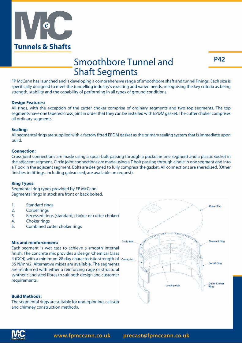
FP McCann has launched and is developing a comprehensive range of smoothbore shaft and tunnel linings. Each size is specifically designed to meet the tunnelling industry’s exacting and varied needs, recognising the key criteria as being strength, stability and the capability of performing in all types of ground conditions.
Design Features:All rings, with the exception of the cutter choker comprise of ordinary segments and two top segments. The top segments have one tapered cross joint in order that they can be installed with EPDM gasket. The cutter choker comprises all ordinary segments.
Sealing:All segmental rings are supplied with a factory fitted EPDM gasket as the primary sealing system that is immediate upon build.
Connection:Cross joint connections are made using a spear bolt passing through a pocket in one segment and a plastic socket in the adjacent segment. Circle joint connections are made using a T bolt passing through a hole in one segment and into a T box in the adjacent segment. Bolts are designed to fully compress the gasket. All connections are sheradised. (Other finishes to fittings, including galvanised, are available on request).
Ring Types:Segmental ring types provided by FP McCann:Segmental rings in stock are front or back bolted.
1. Standard rings2. Corbel rings3. Recessed rings (standard, choker or cutter choker) 4. Choker rings 5. Combined cutter choker rings
Mix and reinforcement:Each segment is wet cast to achieve a smooth internal finish. The concrete mix provides a Design Chemical Class 4 (DC4) with a minimum 28 day characteristic strength of 55 N/mm2. Alternative mixes are available. The segments are reinforced with either a reinforcing cage or structural synthetic and steel fibres to suit both design and customer requirements.
Build Methods:The segmental rings are suitable for underpinning, caisson and chimney construction methods.
Tunnels & Shafts
www.fpmccann.co.uk [email protected]
P43
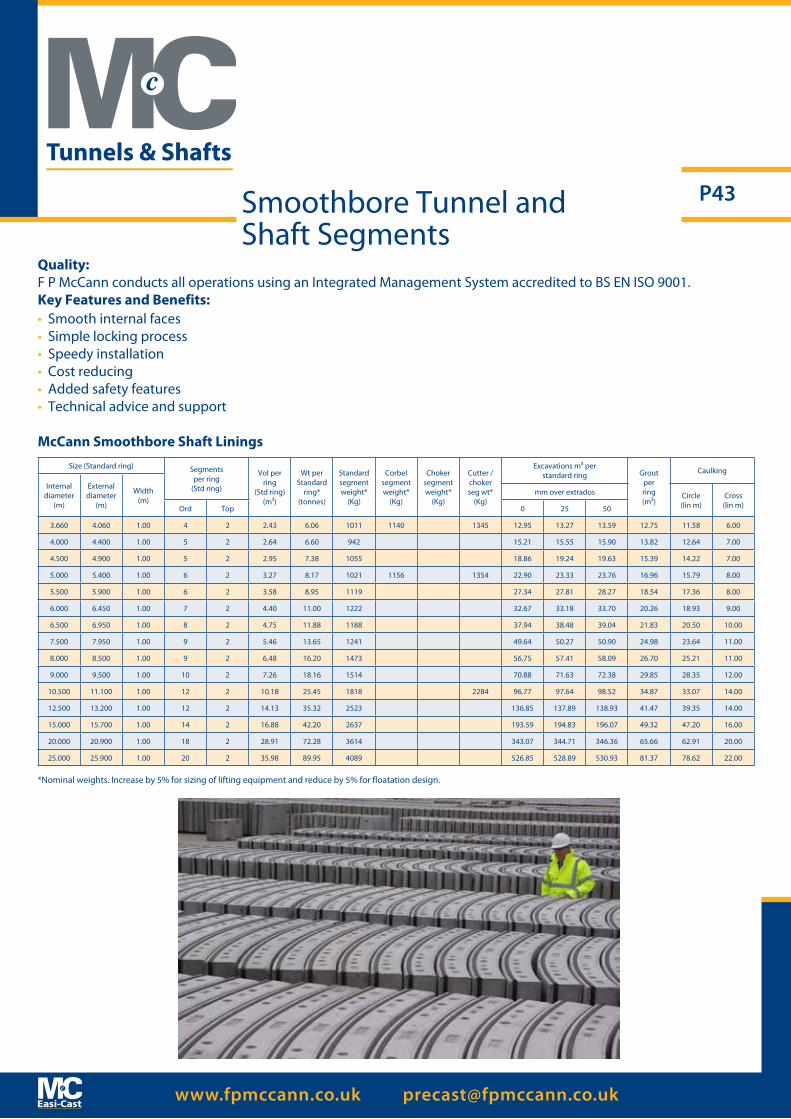
Quality: F P McCann conducts all operations using an Integrated Management System accredited to BS EN ISO 9001.Key Features and Benefits:• Smooth internal faces• Simple locking process• Speedy installation• Cost reducing• Added safety features• Technical advice and support
McCann Smoothbore Shaft LiningsSize (Standard ring) Segments
per ring(Std ring)
Vol perring
(Std ring)(m³)
Wt per Standard
ring*(tonnes)
Standardsegmentweight*
(Kg)
Corbelsegmentweight*
(Kg)
Chokersegmentweight*
(Kg)
Cutter /chokerseg wt*
(Kg)
Excavations m³ perstandard ring Grout
perring(m²)
Caulking
Internaldiameter
(m)
Externaldiameter
(m)
Width(m)
mm over extrados Circle(lin m)
Cross(lin m)Ord Top 0 25 50
3.660 4.060 1.00 4 2 2.43 6.06 1011 1140 1345 12.95 13.27 13.59 12.75 11.58 6.00
4.000 4.400 1.00 5 2 2.64 6.60 942 15.21 15.55 15.90 13.82 12.64 7.00
4.500 4.900 1.00 5 2 2.95 7.38 1055 18.86 19.24 19.63 15.39 14.22 7.00
5.000 5.400 1.00 6 2 3.27 8.17 1021 1156 1354 22.90 23.33 23.76 16.96 15.79 8.00
5.500 5.900 1.00 6 2 3.58 8.95 1119 27.34 27.81 28.27 18.54 17.36 8.00
6.000 6.450 1.00 7 2 4.40 11.00 1222 32.67 33.18 33.70 20.26 18.93 9.00
6.500 6.950 1.00 8 2 4.75 11.88 1188 37.94 38.48 39.04 21.83 20.50 10.00
7.500 7.950 1.00 9 2 5.46 13.65 1241 49.64 50.27 50.90 24.98 23.64 11.00
8.000 8.500 1.00 9 2 6.48 16.20 1473 56.75 57.41 58.09 26.70 25.21 11.00
9.000 9.500 1.00 10 2 7.26 18.16 1514 70.88 71.63 72.38 29.85 28.35 12.00
10.500 11.100 1.00 12 2 10.18 25.45 1818 2284 96.77 97.64 98.52 34.87 33.07 14.00
12.500 13.200 1.00 12 2 14.13 35.32 2523 136.85 137.89 138.93 41.47 39.35 14.00
15.000 15.700 1.00 14 2 16.88 42.20 2637 193.59 194.83 196.07 49.32 47.20 16.00
20.000 20.900 1.00 18 2 28.91 72.28 3614 343.07 344.71 346.36 65.66 62.91 20.00
25.000 25.900 1.00 20 2 35.98 89.95 4089 526.85 528.89 530.93 81.37 78.62 22.00
*Nominal weights. Increase by 5% for sizing of lifting equipment and reduce by 5% for floatation design.
Smoothbore Tunnel andShaft Segments
Tunnels & Shafts
www.fpmccann.co.uk [email protected]
P44
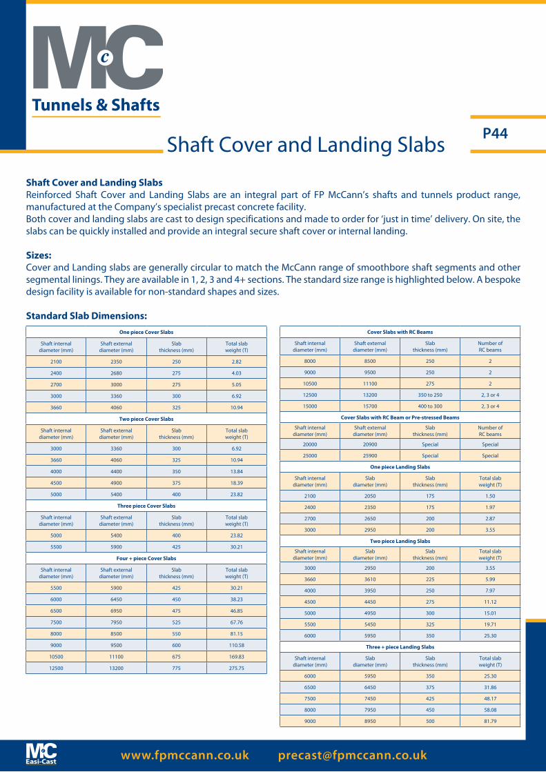
Shaft Cover and Landing SlabsReinforced Shaft Cover and Landing Slabs are an integral part of FP McCann’s shafts and tunnels product range, manufactured at the Company’s specialist precast concrete facility.Both cover and landing slabs are cast to design specifications and made to order for ‘just in time’ delivery. On site, the slabs can be quickly installed and provide an integral secure shaft cover or internal landing.
Sizes:Cover and Landing slabs are generally circular to match the McCann range of smoothbore shaft segments and other segmental linings. They are available in 1, 2, 3 and 4+ sections. The standard size range is highlighted below. A bespoke design facility is available for non-standard shapes and sizes.
Standard Slab Dimensions:
Shaft Cover and Landing Slabs
One piece Cover Slabs
Shaft internaldiameter (mm)
Shaft externaldiameter (mm)
Slab thickness (mm)
Total slabweight (T)
2100 2350 250 2.82
2400 2680 275 4.03
2700 3000 275 5.05
3000 3360 300 6.92
3660 4060 325 10.94
Two piece Cover Slabs
Shaft internaldiameter (mm)
Shaft externaldiameter (mm)
Slab thickness (mm)
Total slabweight (T)
3000 3360 300 6.92
3660 4060 325 10.94
4000 4400 350 13.84
4500 4900 375 18.39
5000 5400 400 23.82
Three piece Cover Slabs
Shaft internaldiameter (mm)
Shaft externaldiameter (mm)
Slab thickness (mm)
Total slabweight (T)
5000 5400 400 23.82
5500 5900 425 30.21
Four + piece Cover Slabs
Shaft internaldiameter (mm)
Shaft externaldiameter (mm)
Slab thickness (mm)
Total slabweight (T)
5500 5900 425 30.21
6000 6450 450 38.23
6500 6950 475 46.85
7500 7950 525 67.76
8000 8500 550 81.15
9000 9500 600 110.58
10500 11100 675 169.83
12500 13200 775 275.75
Cover Slabs with RC Beams
Shaft internaldiameter (mm)
Shaft externaldiameter (mm)
Slab thickness (mm)
Number ofRC beams
8000 8500 250 2
9000 9500 250 2
10500 11100 275 2
12500 13200 350 to 250 2, 3 or 4
15000 15700 400 to 300 2, 3 or 4
Cover Slabs with RC Beam or Pre-stressed Beams
Shaft internaldiameter (mm)
Shaft externaldiameter (mm)
Slab thickness (mm)
Number ofRC beams
20000 20900 Special Special
25000 25900 Special Special
One piece Landing Slabs
Shaft internaldiameter (mm)
Slabdiameter (mm)
Slab thickness (mm)
Total slabweight (T)
2100 2050 175 1.50
2400 2350 175 1.97
2700 2650 200 2.87
3000 2950 200 3.55
Two piece Landing Slabs
Shaft internaldiameter (mm)
Slabdiameter (mm)
Slab thickness (mm)
Total slabweight (T)
3000 2950 200 3.55
3660 3610 225 5.99
4000 3950 250 7.97
4500 4450 275 11.12
5000 4950 300 15.01
5500 5450 325 19.71
6000 5950 350 25.30
Three + piece Landing Slabs
Shaft internaldiameter (mm)
Slabdiameter (mm)
Slab thickness (mm)
Total slabweight (T)
6000 5950 350 25.30
6500 6450 375 31.86
7500 7450 425 48.17
8000 7950 450 58.08
9000 8950 500 81.79
Tunnels & Shafts
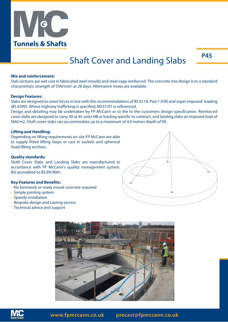
www.fpmccann.co.uk [email protected]
P45
Mix and reinforcement:Slab sections are wet cast in fabricated steel moulds and steel cage reinforced. The concrete mix design is to a standard characteristic strength of 55N/mm2 at 28 days. Alternative mixes are available.
Design Features:Slabs are designed to resist forces in line with the recommendations of BS 8110: Part 1 (Fill) and super imposed loading (BS 6399). Where highway trafficking is specified, BD37/01 is referenced. Design and detailing may be undertaken by FP McCann or to the to the customers design specification. Reinforced cover slabs are designed to carry 30 or 45 units HB or loading specific to contract, and landing slabs an imposed load of 5kN/m2. Shaft cover slabs can accommodate up to a maximum of 4.0 metres depth of fill.
Lifting and Handling:Depending on lifting requirements on site FP McCann are able to supply fitted lifting loops or cast in sockets and spherical head lifting anchors.
Quality standards:Shaft Cover Slabs and Landing Slabs are manufactured in accordance with FP McCann’s quality management system, BSI accredited to BS EN 9001.
Key Features and Benefits:• No formwork or ready mixed concrete required• Simple jointing system• Speedy installation• Bespoke design and casting service• Technical advice and support
Shaft Cover and Landing Slabs
Tunnels & Shafts
www.fpmccann.co.uk [email protected]
P46
FP McCann Caisson Range
Caissons Shafts DN Available Depths (mm) Barrel DN Wall Thickness Lifting Hole
mm 1000 750 500 mm mm Qty per unit
2100 √ √ √ 2350 125 3 No. RD24 Wavy Tail Inserts
2400 √ √ √ 2680 140 3 No. RD24 Wavy Tail Inserts
2700 √ √ √ 3000 150 3 No. RD30 Wavy Tail Inserts
3000 √ √ √ 3360 180 3 No. RD30 Wavy Tail Inserts
3600 √ √ √ 3970 185 3 No. RD30 Wavy Tail Inserts
4000* √ √ X 4400 200 6 No. RD36 Wavy Tail Inserts
*DN4000 supplied as a two piece unit.
FP McCann manufactures a range of reinforcing units suitable for sinking by the caisson method. Caisson shaft units can be supplied with diameters of 2100mm up to 4000mm. Caissons are manufactured in accordance with the requirements of BS EN 1917, and have Kitemark certification where relevant to the scope of BS5911 (2100mm – 3000mm diameters). However 3600mm and 4000mm diameters remain operative within the scope of the ISO9001 accredited Quality Management System.
Open caisson-sinking techniques permit a shaft structure to be progressively sunk, either under its own weight or with the aid of caisson jacks, in a controlled manner from the surface to a predetermined depth. Caisson shafts are constructed using a metal cutter ring and base section with rings being added on top as excavation proceeds. The technique is suited to shaft construction through weak soils, high-plasticity clays, silts, sands and gravels; particularly below the water table.
Caisson Units
Tunnels & Shafts
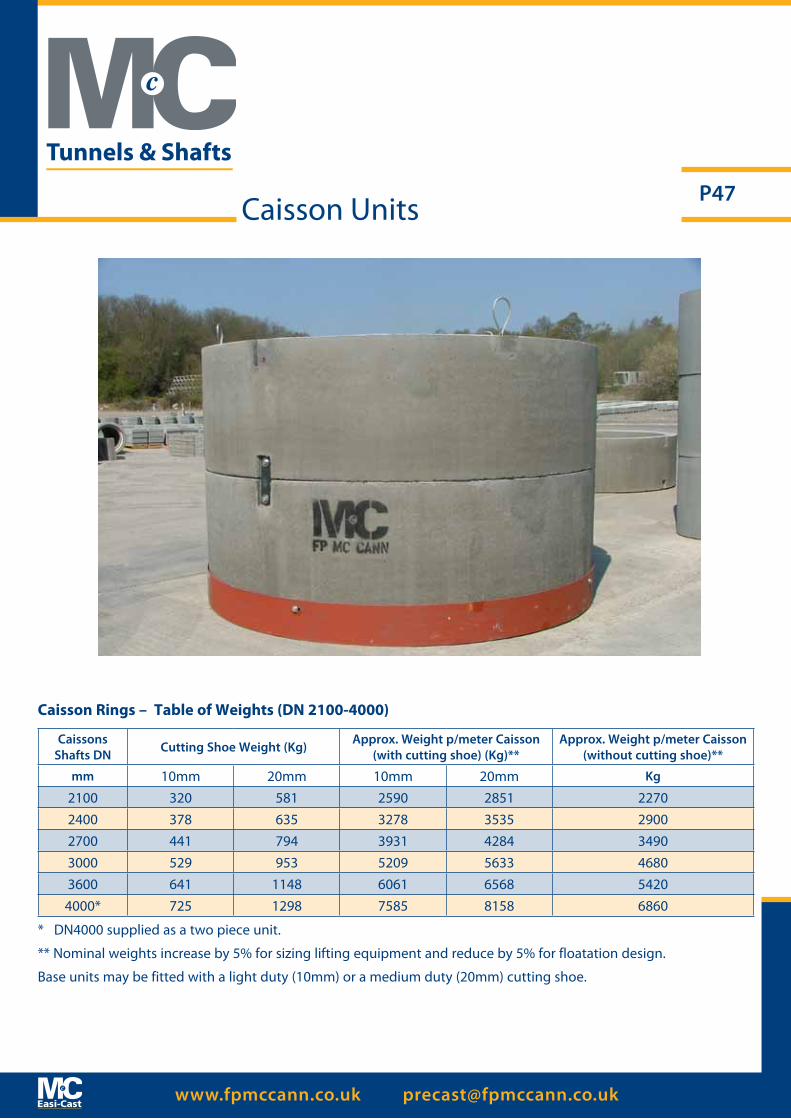
www.fpmccann.co.uk [email protected]
P47
Caisson Rings – Table of Weights (DN 2100-4000)
Caissons Shafts DN Cutting Shoe Weight (Kg) Approx. Weight p/meter Caisson
(with cutting shoe) (Kg)**Approx. Weight p/meter Caisson
(without cutting shoe)**
mm 10mm 20mm 10mm 20mm Kg
2100 320 581 2590 2851 22702400 378 635 3278 3535 29002700 441 794 3931 4284 34903000 529 953 5209 5633 46803600 641 1148 6061 6568 54204000* 725 1298 7585 8158 6860
* DN4000 supplied as a two piece unit.
** Nominal weights increase by 5% for sizing lifting equipment and reduce by 5% for floatation design.
Base units may be fitted with a light duty (10mm) or a medium duty (20mm) cutting shoe.
Caisson Units
Tunnels & Shafts
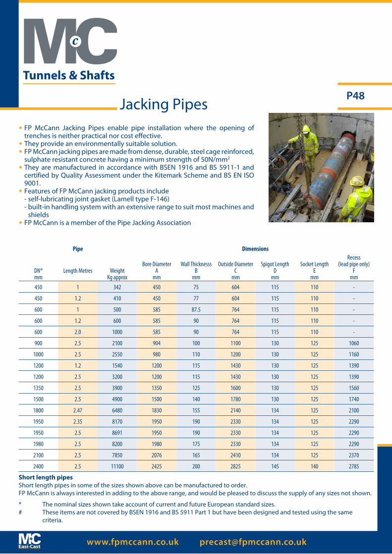
www.fpmccann.co.uk [email protected]
P48Jacking Pipes
Pipe Dimensions
DN* mm
Length Metres Weight Kg approx
Bore DiameterA
mm
Wall ThicknesssB
mm
Outside DiameterC
mm
Spigot LengthD
mm
Socket LengthE
mm
Recess (lead pipe only)
Fmm
450 1 342 450 75 604 115 110 -
450 1.2 410 450 77 604 115 110 -
600 1 500 585 87.5 764 115 110 -
600 1.2 600 585 90 764 115 110 -
600 2.0 1000 585 90 764 115 110 -
900 2.5 2100 904 100 1100 130 125 1060
1000 2.5 2550 980 110 1200 130 125 1160
1200 1.2 1540 1200 115 1430 130 125 1390
1200 2.5 3200 1200 115 1430 130 125 1390
1350 2.5 3900 1350 125 1600 130 125 1560
1500 2.5 4900 1500 140 1780 130 125 1740
1800 2.47 6480 1830 155 2140 134 125 2100
1950 2.35 8170 1950 190 2330 134 125 2290
1950 2.5 8691 1950 190 2330 134 125 2290
1980 2.5 8200 1980 175 2330 134 125 2290
2100 2.5 7850 2076 165 2410 134 125 2370
2400 2.5 11100 2425 200 2825 145 140 2785
Short length pipesShort length pipes in some of the sizes shown above can be manufactured to order.FP McCann is always interested in adding to the above range, and would be pleased to discuss the supply of any sizes not shown.
* The nominal sizes shown take account of current and future European standard sizes.# These items are not covered by BSEN 1916 and BS 5911 Part 1 but have been designed and tested using the same
criteria.
• FP McCann Jacking Pipes enable pipe installation where the opening of trenches is neither practical nor cost effective.
• They provide an environmentally suitable solution.• FP McCann jacking pipes are made from dense, durable, steel cage reinforced,
sulphate resistant concrete having a minimum strength of 50N/mm2
• They are manufactured in accordance with BSEN 1916 and BS 5911-1 and certified by Quality Assessment under the Kitemark Scheme and BS EN ISO 9001.
• Features of FP McCann jacking products include - self-lubricating joint gasket (Lamell type F-146) - built-in handling system with an extensive range to suit most machines and
shields • FP McCann is a member of the Pipe Jacking Association
Tunnels & Shafts

www.fpmccann.co.uk [email protected]
P49
Infrastructure & Power
Power Infrastructure Cable Ducting Systems
FP McCann offers a specialist range of precast reinforced concrete cable troughs and ducting systems used to house and protect most types of services, including power and communication cables and pipes for gas, water and chemicals. Easi-Duct access troughs and ducts can be buried underground, located above, or flush with surface levels to provide protection against accidental or malicious damage and to offer easy access for maintenance and repair. Three types of flush fitting lids are supplied in either reinforced precast concrete, GRP composite, or steel tray. All are designed and tested for loading group class to BS EN 124.
Typical Easi-Duct applications include; rail and highway infrastructure; power stations; gas, oil and chemical installations; industrial, commercial and domestic developments; docks and harbours; water and sewage treatment plants.
BenefitsCompared with the alternatives of direct burying of cables and pipes or overhead suspension, Easi-Duct has a number of advantages:-
• Carries multiple services for different utility providers
• Non conductive to electricity
• Chemically resistant concrete
• Cables buried at depth are unexposed to weather changes (i.e. freezing or overheating)
• High strength load bearing units
• Easy access for cable repair, splicing or new cable additions
• Whole life costing of precast concrete is lower than other forms of ducting construction
• FP McCann can produce specialist units moulded to requirement
Design FeaturesThe troughs, ducts and lids are designed and tested for load classes A15, B125, C250 and D400. For loadings E600 and F900, Easi- Duct systems are designed, tested and manufactured specific to order.Standard troughs are manufactured with either a 50mm deep rebate to accommodate a class A or B flush fitting lid, or 100mm deep to accommodate class C or D lids.

www.fpmccann.co.uk [email protected]
P50
QualityFP McCann Easi-Duct systems are designed, manufactured and and strength tested to comply with loading criteria as set out in accordance with BS EN 1433 (Troughs) and BS EN 124 (Lids). All operations are conducted in accordance with FP McCann’s quality management system, BSI accredited to BS EN ISO 9001.
Reference(width x depth x
length)Trough Coding Description Loading group
Class to BS EN 124
s/w* nominal
kg
Supplied with Lid reference
Trough Dimensions (mm)
A B C D E F
1250 x 1250 x 1000
MT 1250 1250 AB SL
1250W x 1250D x 1000L Trough with 50mm rebate 5T SWL A and B 1915 Special to order 1250 1300 1500 1380 1505 1700
MT 1250 1250 CD LL
1250W x 1250D x 1000L Trough with 100mm rebate 11.5T SWL C and D 1915 Special to order 1250 1250 1500 1375 1505 1700
1250 x 1000 x 1000
MT 1250 1000 AB SL
1250W x 1000D x 1000L Trough with 50mm rebate 5T SWL A and B 1708 Special to order 1250 1050 1250 1355 1505 1700
MT 1250 1000 CD LL
1250W x 1000D x 1000L Trough with 100mm rebate 11.5T SWL C and D 1708 Special to order 1250 1000 1250 1350 1505 1700
1250 x 750 x 1000
MT 1250 750 AB SL
1250W x 750D x 1000L Trough with 50mm rebate 5T SWL A and B 1484 Special to order 1250 800 1000 1330 1505 1700
MT 1250 750 CD LL
1250W x 750D x 1000L Trough with 100mm rebate 11.5T SWL C and D 1484 Special to order 1250 750 1000 1325 1505 1700
1000 x 1000 x 1000
MT 1000 1000 AB SL
1000W x 1000D x 1000L Trough with 50mm rebate 5T SWL A and B 1539
ML 1000 50 ODT A or ML 1000 50 CDS A
or ML 1000 50 CDS B1000 1050 1250 1105 1230 1425
MT 1000 1000 CD LL
1000W x 1000D x 1000L Trough with 100mm rebate 11.5T SWL C and D 1539 ML 1000 100 CDS CD
or ML 1000 100 RC AB 1000 1000 1250 1100 1230 1425
1000 x 750 x 1000
MT 1000 750 AB SL
1000W x 750D x 1000L Trough with 50mm rebate 5T SWL A and B 1331
ML 1000 50 ODT A or ML 1000 50 CDS A
or ML 1000 50 CDS B1000 800 1000 1080 1230 1425
MT 1000 750 CD LL
1000W x 750D x 1000L Trough with 100mm rebate 11.5T SWL C and D 1331 ML 1000 100 CDS CD
or ML 1000 100 RC AB 1000 750 1000 1075 1230 1425
1000 x 500 x 1000
MT 1000 500 AB SL
1000W x 500D x 1000L Trough with 50mm rebate 5T SWL A and B 1108
ML 1000 50 ODT A or ML 1000 50 CDS A
or ML 1000 50 CDS B1000 550 750 1055 1230 1425
MT 1000 500 CD LL
1000W x 500D x 1000L Trough with 100mm rebate 11.5T SWL C and D 1108 ML 1000 100 CDS CD
or ML 1000 100 RC AB 1000 500 750 1050 1230 1425
Trough Table 1: 1000 wide to 1250 wide
* maximum self weight = nominal self + 5%, which should be used to size lifting equipment
Power Infrastructure Cable Ducting Systems
Infrastructure & Power

www.fpmccann.co.uk [email protected]
P51Power Infrastructure Cable Ducting Systems
Reference(width x depth x
length)Coding Description Loading group
Class to BS EN 124
s/w *nominal
kg
Supplied withLid reference
Trough Dimensions (mm)
A B C D E F
750 x 750 x 1000MT 750 750 AB SL 750W x 750D x 1000L Trough with 50mm
rebate 5T SWL A and B 1115ML 750 50 ODT A or
ML 750 50 CDS Aor ML 750 50 CDS B
750 800 1000 830 955 1125
MT 750 750 CD LL 750W x 750D x 1000L Trough with 100mm rebate 11.5T SWL C and D 1115 ML 750 100 CDS CD or
ML 750 100 RC AB 750 750 1000 830 935 1125
750 x 500 x 1000MT 750 500 AB SL 750W x 500D x 1000L Trough with 50mm
rebate 5T SWL A and B 923ML 750 50 ODT A or
ML 750 50 CDS Aor ML 750 50 CDS B
750 550 750 805 955 1125
MT 750 500 CD LL 750W x 500D x 1000L Trough with 100mm rebate 11.5T SWL C and D 923 ML 750 100 CDS CD or
ML 750 100 RC AB 750 500 750 805 935 1125
600 x 600 x 1000
MT 600 600 ABCD SL
600W x 600D x 1000L Trough with 50mm rebate 11.5T SWL A,B,C &D 810
ML 600 50 ODT A or ML 600 50 CDS A
or ML 600 50 CDS B570 600 800 630 750 900
MT 600 600 ABCD LL
600W x 600D x 1000L Trough with 100mm rebate 11.5T SWL A,B,C &D 810 ML 600 100 CDS CD or
ML 600 100 RC AB 570 550 800 630 740 900
600 x 300 x 1000
MT 600 300 ABCD SL
600W x 300D x 1000L Trough with 50mm rebate 11.5T SWL A,B,C &D 596
ML 600 50 ODT A or ML 600 50 CDS A
or ML 600 50 CDS B570 300 500 600 750 900
MT 600 300 ABCD LL
600W x 300D x 1000L Trough with 100mm rebate 11.5T SWL A,B,C &D 596 ML 600 100 CDS CD or
ML 600 100 RC AB 570 250 500 600 640 900
350 x 300 x 1000
MT 350 300 ABCD SL
350W x 300D x 1000L Trough with 50mm rebate 11.5T SWL A,B,C &D 450
ML 350 50 ODT A or ML 350 50 CDS A
or ML 350 50 CDS B350 350 525 385 510 635
MT 350 300 ABCD LL
350W x 300D x 1000L Trough with 100mm rebate 11.5T SWL A,B,C &D 450 ML 350 100 CDS CD or
ML 350 100 RC AB 350 300 525 385 490 635
Trough Table 2: 350 wide to 750 wide
* maximum self weight = nominal self + 5%, which should be used to size lifting equipment
Infrastructure & Power
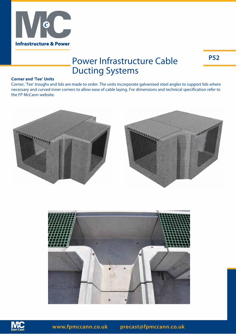
www.fpmccann.co.uk [email protected]
P52
Corner and ‘Tee’ UnitsCorner, ‘Tee’ troughs and lids are made to order. The units incorporate galvanised steel angles to support lids where necessary and curved inner corners to allow ease of cable laying. For dimensions and technical specification refer to the FP McCann website.
Power Infrastructure Cable Ducting Systems
Infrastructure & Power
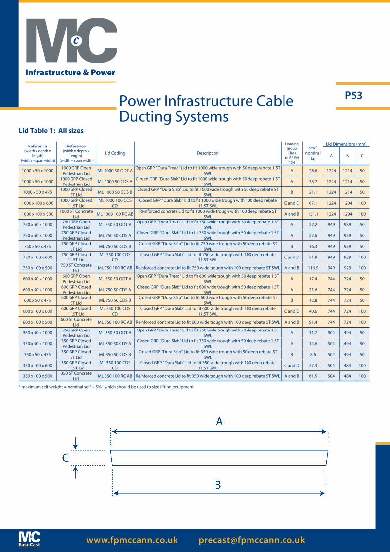
www.fpmccann.co.uk [email protected]
P53
Reference(width x depth x
length) (width = span width)
Reference(width x depth x
length) (width = span width)
Lid Coding Description
LoadinggroupClass
to BS EN 124
s/w*nominal
kg
Lid Dimensions (mm)
A B C
1000 x 50 x 1000 1000 GRP Open Pedestrian Lid ML 1000 50 ODT A Open GRP “Dura Tread” Lid to fit 1000 wide trough with 50 deep rebate 1.5T
SWL A 28.6 1224 1214 50
1000 x 50 x 1000 1000 GRP Closed Pedestrian Lid ML 1000 50 CDS A Closed GRP “Dura Slab” Lid to fit 1000 wide trough with 50 deep rebate 1.5T
SWL A 35.7 1224 1214 50
1000 x 50 x 475 1000 GRP Closed 5T Lid ML 1000 50 CDS B Closed GRP “Dura Slab” Lid to fit 1000 wide trough with 50 deep rebate 5T
SWL B 21.1 1224 1214 50
1000 x 100 x 600 1000 GRP Closed 11.5T Lid
ML 1000 100 CDS CD
Closed GRP “Dura Slab” Lid to fit 1000 wide trough with 100 deep rebate 11.5T SWL C and D 67.1 1224 1204 100
1000 x 100 x 500 1000 5T Concrete Lid ML 1000 100 RC AB Reinforced concrete Lid to fit 1000 wide trough with 100 deep rebate 5T
SWL A and B 151.1 1224 1204 100
750 x 50 x 1000 750 GRP Open Pedestrian Lid ML 750 50 ODT A Open GRP “Dura Tread” Lid to fit 750 wide trough with 50 deep rebate 1.5T
SWL A 22.2 949 939 50
750 x 50 x 1000 750 GRP Closed Pedestrian Lid ML 750 50 CDS A Closed GRP “Dura Slab” Lid to fit 750 wide trough with 50 deep rebate 1.5T
SWL A 27.6 949 939 50
750 x 50 x 475 750 GRP Closed 5T Lid ML 750 50 CDS B Closed GRP “Dura Slab” Lid to fit 750 wide trough with 50 deep rebate 5T
SWL B 16.3 949 939 50
750 x 100 x 600 750 GRP Closed 11.5T Lid
ML 750 100 CDS CD
Closed GRP “Dura Slab” Lid to fit 750 wide trough with 100 deep rebate 11.5T SWL C and D 51.9 949 929 100
750 x 100 x 500 750 5T Concrete Lid ML 750 100 RC AB Reinforced concrete Lid to fit 750 wide trough with 100 deep rebate 5T SWL A and B 116.9 949 929 100
600 x 50 x 1000 600 GRP Open Pedestrian Lid ML 750 50 ODT A Open GRP “Dura Tread” Lid to fit 600 wide trough with 50 deep rebate 1.5T
SWL A 17.4 744 724 50
600 x 50 x 1000 600 GRP Closed Pedestrian Lid ML 750 50 CDS A Closed GRP “Dura Slab” Lid to fit 600 wide trough with 50 deep rebate 1.5T
SWL A 21.6 744 724 50
600 x 50 x 475 600 GRP Closed 5T Lid ML 750 50 CDS B Closed GRP “Dura Slab” Lid to fit 600 wide trough with 50 deep rebate 5T
SWL B 12.8 744 724 50
600 x 100 x 600 600 GRP Closed 11.5T Lid
ML 750 100 CDS CD
Closed GRP “Dura Slab” Lid to fit 600 wide trough with 100 deep rebate 11.5T SWL C and D 40.6 744 724 100
600 x 100 x 500 600 5T Concrete Lid ML 750 100 RC AB Reinforced concrete Lid to fit 600 wide trough with 100 deep rebate 5T SWL A and B 91.4 744 724 100
350 x 50 x 1000 350 GRP Open Pedestrian Lid ML 350 50 ODT A Open GRP “Dura Tread” Lid to fit 350 wide trough with 50 deep rebate 1.5T
SWL A 11.7 504 494 50
350 x 50 x 1000 350 GRP Closed Pedestrian Lid ML 350 50 CDS A Closed GRP “Dura Slab” Lid to fit 350 wide trough with 50 deep rebate 1.5T
SWL A 14.6 504 494 50
350 x 50 x 475 350 GRP Closed 5T Lid ML 350 50 CDS B Closed GRP “Dura Slab” Lid to fit 350 wide trough with 50 deep rebate 5T
SWL B 8.6 504 494 50
350 x 100 x 600 350 GRP Closed 11.5T Lid
ML 350 100 CDS CD
Closed GRP “Dura Slab” Lid to fit 350 wide trough with 100 deep rebate 11.5T SWL C and D 27.3 504 484 100
350 x 100 x 500 350 5T Concrete Lid ML 350 100 RC AB Reinforced concrete Lid to fit 350 wide trough with 100 deep rebate 5T SWL A and B 61.5 504 484 100
Power Infrastructure Cable Ducting Systems
* maximum self weight = nominal self + 5%, which should be used to size lifting equipment
Lid Table 1: All sizes
Infrastructure & Power
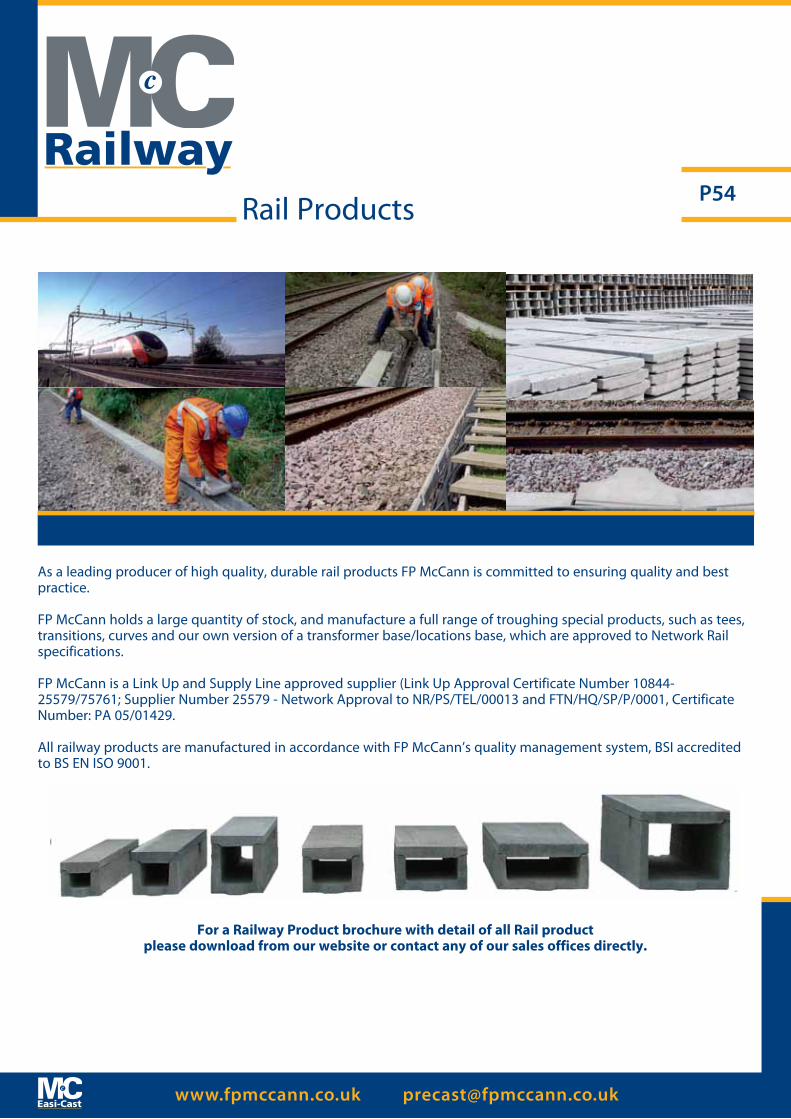
www.fpmccann.co.uk [email protected]
P54
As a leading producer of high quality, durable rail products FP McCann is committed to ensuring quality and best practice. FP McCann holds a large quantity of stock, and manufacture a full range of troughing special products, such as tees, transitions, curves and our own version of a transformer base/locations base, which are approved to Network Rail specifications.
FP McCann is a Link Up and Supply Line approved supplier (Link Up Approval Certificate Number 10844-25579/75761; Supplier Number 25579 - Network Approval to NR/PS/TEL/00013 and FTN/HQ/SP/P/0001, Certificate Number: PA 05/01429.
All railway products are manufactured in accordance with FP McCann’s quality management system, BSI accredited to BS EN ISO 9001.
Rail Products
Railway
For a Railway Product brochure with detail of all Rail product please download from our website or contact any of our sales offices directly.

www.fpmccann.co.uk [email protected]
P55
From our recently extended factory at Cadeby, we combine over 30 years experience to provide an extensive range of attractive, durable and practical fencing solutions.
The range includes: slotted posts, with gravel boards to suit; morticed posts; recessed posts; chainlink posts; universal posts and screed rails.
Our gravel boards are available in a selection of attractive designs including brick and rock-faced patterns.
Concrete fence posts are becoming a popular alternative to wooden posts, offering greater strength and durability, and of course, will last much longer.
We also manufacture a range of lightweight products - Fenn-Lite - ideally suited for one-man installation, but with the same strength and durability of our other products.
Available nationwide
Our sales team is on hand to discuss your requirements and can recommend the right product for you.
We can deliver our fencing products anywhere in the UK, or alternatively, you can collect direct from the factory.
All fencing products are manufactured in accordance with FP McCann’s quality management system, BSI accredited to BS EN ISO 9001.
For a Fencing Product brochure with detail of our range please download from our website or contact any of our sales offices directly.
Fencing Products

www.fpmccann.co.uk [email protected]
P56
Description A - Width (mm) B - Height (mm) C - Length (mm) Number (p/tonne)
Bullnosed 125 255 915 14
Full Batter 125 255 915 16
Half Batter 125 255 915 15
Full Batter 150 255 915 13
Half Batter 150 255 915 14
Channel 125 255 915 15
Flat & Round Top Edgings 50 150 915 60
Dwarf Wall 90 380 915 15
Dropper Kerb 125 255 - 150 915 20
Kerbs & Channels Range(N. Ireland Only)
Easi-Kerb
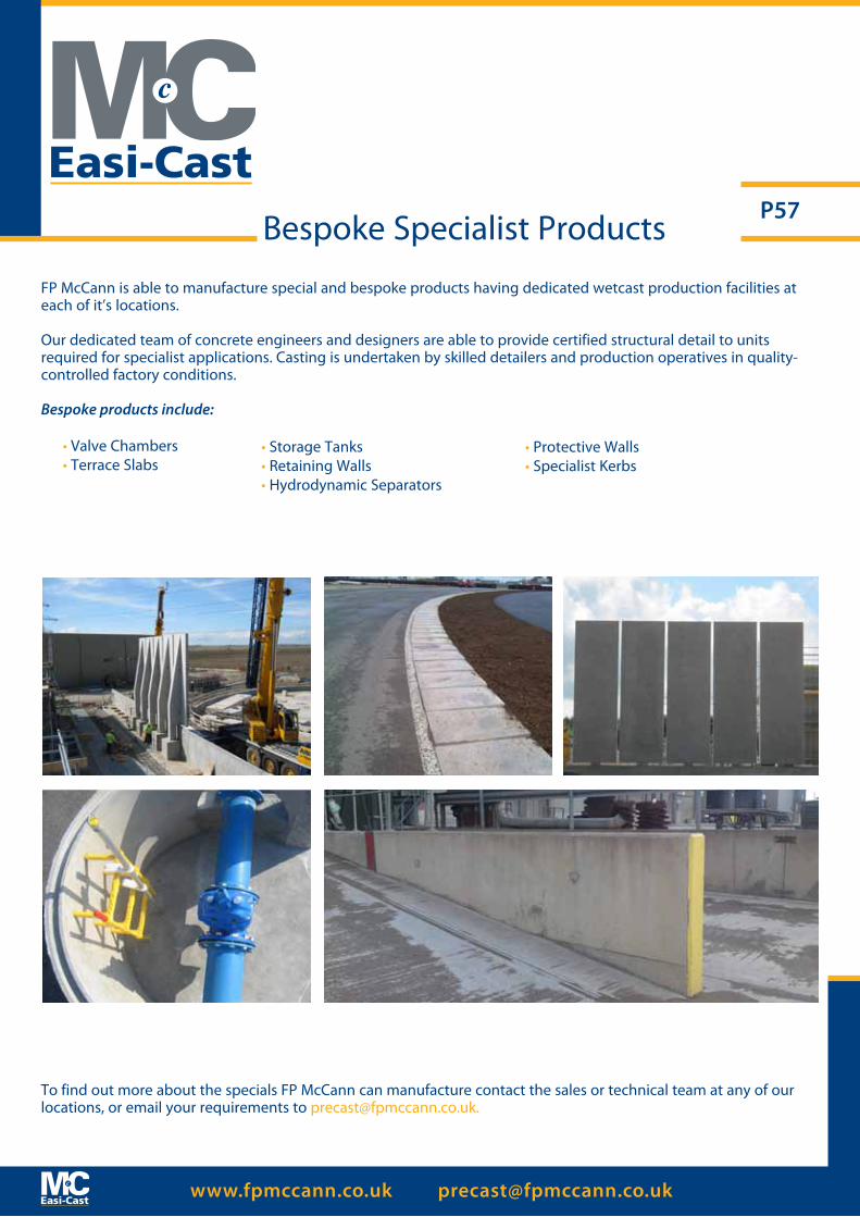
www.fpmccann.co.uk [email protected]
P57Bespoke Specialist Products
To find out more about the specials FP McCann can manufacture contact the sales or technical team at any of our locations, or email your requirements to [email protected].
FP McCann is able to manufacture special and bespoke products having dedicated wetcast production facilities at each of it’s locations.
Our dedicated team of concrete engineers and designers are able to provide certified structural detail to units required for specialist applications. Casting is undertaken by skilled detailers and production operatives in quality-controlled factory conditions.
Bespoke products include:
• Valve Chambers• Terrace Slabs
• Storage Tanks• Retaining Walls• Hydrodynamic Separators
• Protective Walls• Specialist Kerbs

Knockloughrim Quarry3 Drumard Road
MagherafeltBT45 8QA
Tel: 028 7964 2558Fax: 028 7964 4224
EllistownWhitehill RoadLeicestershire
EnglandLE67 1ET
Tel: 01530 240000Fax: 01530 240013
AlnwickLittle Houghton
NorthumberlandEnglandNE66 3JX
Tel: 01665 577653Fax: 01665 577711
TelfordDoseley Telford
ShropshireTF4 3BX
Tel: 01952 630300Fax: 01952 501537
CadebyBrasscote Lane
Cadeby, NuneatonWarks
CV13 0BB
Tel: 01455 290780Fax: 01455 292189
Precast Office Locations
Head Office