product category rules for building-related products · pdf fileproduct category rules for...
TRANSCRIPT
Product Category Rules for Building-Related Products and Services
Adapted for UL Environment from the range of Environ-mental Product Declarations of Institute Construction and Environment e.V. (IBU) Part A: Calculation Rules for the Life Cycle As-sessment and Requirements on the Project report Version 1.3 www.bau-umwelt.de www.ul.com/businesses/environment

2 Product Category Rules for building products Part A
Imprint:
Issued by:
Tracking the versions
© Institut Bauen und Umwelt e.V. Any type of reproduction, including excerpts thereof, shall re-quire the approval of the publisher.
Institut Bauen und Umwelt e.V.
Rheinufer 108 53639 Königswinter
Version Comments As of
1.0 Implementing the EN 15804 in the IBU range regulations. This document replaces the previ-ous “General Principles” (valid as at 20.01.2006).
27.09.2011
1.1 Adapting the standard quotations in accord-ance with the latest version of EN 15804.
20.09.2012
1.2 Additional texts and decisions by the SVA (from 22.03.2013) implemented.
03.04.2013
1.3 Revision to harmonize and regionalize to North American applicability under mutual recogni-tion program with UL Environment (Refer to Section12 for specific changes)
19.06.2014

3
Product Category Rules for building products Part A
Table of Contents 1 General ........................................................................................................................... 4 2 Scope .............................................................................................................................. 4 3 Content, structure and accessibility of the project report .......................................... 4 4 General information in the project report .................................................................... 4 5 Goal of the study ........................................................................................................... 4 6 Scope of the study ......................................................................................................... 5
6.1 Declared/Functional unit ..................................................................................... 5 6.2 Declaration of construction product classes ........................................................ 5 6.3 Product description ............................................................................................. 6 6.4 Area of application of the construction product ................................................... 6 6.5 System boundaries ............................................................................................. 6
6.5.1 A1-A3, Product stage, Information modules ........................................................ 6 6.5.2 A4-A5, Construction stage, Information modules ................................................. 8 6.5.3 B1-B5, Use stage information modules related to the basic fabric ....................... 9 6.5.4 B6-B7, Use stage information modules relating to operation of the building ...... 12 6.5.5 C1-C4 End-of-life stage information modules .................................................... 13 6.5.6 Benefits and loads beyond the product system boundary, information module .. 15 6.5.7 Power mix ......................................................................................................... 16 6.5.8 CO2 certificates ................................................................................................. 16 6.5.9 Description of the system boundary in the project report ................................... 17
6.6 Criteria for the exclusion of inputs and outputs ..................................................17 7 Life Cycle Inventory Analysis ..................................................................................... 18
7.1 Collecting data and calculation procedures ........................................................18 7.2 Developing product level scenarios ...................................................................18 7.3 Selecting data / background data ......................................................................19 7.4 Data / Background data quality requirements ....................................................19 7.5 Allocations .........................................................................................................21
7.5.1 Co-product allocation ......................................................................................... 22 7.5.2 Allocation of multi-input processes .................................................................... 23 7.5.3 Allocation procedure for reuse, recycling and recovery ...................................... 23 7.5.4 Description of the allocation processes in the project report .............................. 24
7.6 Description of the unit processes in the project report .......................................25 8 Life Cycle Inventory Analysis and Impact Assessment ............................................ 25
8.1 Indicators for the Life Cycle Inventory Analysis as per EN 15804 ......................25 8.2 Indicators for Impact Assessment as per EN 15804 ..........................................28
9 Life cycle interpretation .............................................................................................. 29 10 Documentation of additional information .................................................................. 30
10.1 Laboratory results and scenario-related information ........................................30 10.2 Documentation for calculating the Reference Service Life (RSL) .....................30
11 References ................................................................................................................... 30

4 Product Category Rules for building products Part A
1 General
This document cites the standard EN 15804 in many sections. Certain clauses of the standard texts have been omitted for reasons of readability, however not with the inten-tion to compromise the conformity of this document with EN 15804. Those clauses are marked as [...].
2 Scope
This document is the PCR document for building-related products and –services. It spec-ifies the calculation rules in accordance with EN 15804 for the Life Cycle Assessment of IBU EPDs as well as the requirements on the project report to the Life Cycle Assess-ment. A project report on the EPD must be submitted for each Environmental Product Declaration (EPD) registered with UL Environment (ULE).
3 Content, structure and accessibility of the project report
The project report represents the systematic and comprehensive summary of project documentation with the objective of supporting the verification of an EPD. The project report must document that the information on which the Life Cycle Assessment is based as well as the additional information contained in an EPD meet the requirements of this document.
The project report must contain all of the data and information of importance for the de-tails published in the EPD and required in this set of rules. Particular care must be given to comprehensible explanations as to how the data and information declared in the EPD arises from the Life Cycle Assessment and how – if declared – the reference service life (RSL) was established.
The structure of the project report shall follow the structure of this PCR document based on EN 15804.
The project report must be accessible to the verifier under the conditions of confidentiali-ty (see ISO 14025).
The project report is not part of the public communication.
4 General information in the project report
The project report must contain the following general information: → the client commissioning the Life Cycle Assessment, internal or external Life
Cycle analysts → the report date → indications that the Life Cycle Assessment was performed in agreement with
the requirements of these Product Category Rules with reference to EN 15804.
5 Goal of the study
The goal of the study must be outlined in the project report as regards the following: → reasons for performing the study → intended use → target group, i.e. whether the information and data for an EPD is intended for
business-to-business and/or business-to-consumer communication.

5
Product Category Rules for building products Part A
6 Scope of the study
6.1 Declared/Functional unit
The Life Cycle Assessment of the construction product must be calculated for a declared or functional unit as specified in Part B of the Product Category Rules for the product group which includes the product to be declared. If the entire life cycle of the construction product is to be declared, a functional unit shall be referred to in conformance with EN 15804.
NOTE If the entire life cycle is declared, it is imperative that a reference service life (RSL) is indicated; see section 10.2.
Usually, the declared unit refers to the product "cradle to factory gate". If a manufacturer sells and declares a system, the declared unit may also refer to the product "as installed" i.e.to the construction lot (see also Section 6.5.2).
A declared/functional unit shall be declared in the exact unit(s) specified in the PCR, and not partially, e.g. 0.1 m3 insulating material instead of 1 m3. Standard units can however be declared (e.g. 1 m2 of a defined thickness and density of an insulating material), whereby conversion to the declared/functional unit designated in the PCR must be pos-sible. Details are described by Part B of the PCR applicable for a given construction product.
The selected declared or functional unit must be documented in the project report. In addition, a mass conversion factor of the declared unit shall be indicated.
6.2 Declaration of construction product classes
The classification of construction products and their respective EPDs can significantly reduce the effort associated with drawing up an EPD. The following nomenclature ap-plies for ULE Declarations:
1. Manufacturer declaration:
1a) Declaration of a specific product from a manufacturer’s plant 1b) Declaration of a specific product as an average from several of the manufactur-
er’s plants 1c) Declaration of an average product from a manufacturer’s plant 1d) Declaration of an average product as an average from several of the manufactur-
er’s plants
2. Manufacturer group declaration:
2a) Declaration of a specific product as an average from several manufacturers’ plants
2b) Declaration of an average product as an average from several manufacturers’ plants
A standard or reference product can also be declared which describes a specific (usually typical) product.
6 Product Category Rules for building products Part A
Unless otherwise specified in Part B of the product category rules applicable to a con-struction product, classification and therefore the declared unit for one or several prod-ucts can take the following form:
→ The values of the Life Cycle Assessment can be derived from the declared prod-uct for any product in the class via rules to be documented, e.g. for comparable products of varying density or
→ an “average” or “representative” product is declared, or → the product with the most environmental impact is declared as representative for a
class.
To be indicated in the project report:
→ Calculation rules for forming averages in a declaration based on averaged data, e.g. when a declared/functional unit has been defined for:
→ a group of similar products from various manufacturers or → the same product from various production locations
→ Representativeness of the average
6.3 Product description
The declared product must be described with regards to its technical and functional specifications.
6.4 Area of application of the construction product
The area of application for the declared product must be described.
6.5 System boundaries
The system boundaries of the ULE EPD follow the modular structure in line with EN 15804.
[EN 15804, section 6.2]: “The environmental information of an EPD covering all life cycle stages (“cradle to grave”) shall be subdivided into the information module groups A1-A3, A4-A5, B1-B5, B6-B7, C1-C4 and module D. Only the declaration of the product stage modules, A1-A3, is required for compliance with this standard. The declaration of the modules of the other life cycle stages is optional.
Information modules within any of the life cycle stages are communicated depending on the types of EPD as specified in 6.2. They include impacts and aspects related to the modules in which they occur (i.e. production, transport, waste processing and end-of-life stage) Losses or wastage are also considered in the modules in which they occur).”
6.5.1 A1-A3, Product stage, Information modules
[EN 15804, section 6.2.2]: “The product stage includes:
A1 raw material extraction and processing, processing of secondary material in-put (e.g. recycling processes)
A2 transport to the manufacturer A3 manufacturing
7
Product Category Rules for building products Part A
including provision of all materials, products and energy, as well as waste processing up to the end-of-waste state (Clause 6.3.4.5 and Annex B) or disposal of final residues dur-ing the product stage.”
[EN 15804, section 6.3.4.2]: “The product stage is an information module required to be included in the EPD. […] The system boundary to nature is set to include those process-es that provide the material and energy inputs into the system and the following manu-facturing and transport processes up to the factory gate as well as the processing of any waste arising from those processes.
In the case of input of secondary materials or energy recovered from secondary fuels, the system boundary between the system under study and the previous system (provid-ing the secondary materials) is set where outputs of the previous system, e.g. materials, products or energy or building elements, reach the end-of-waste stage (see [also EN 15804] section 6.3.4.5 and Annex B).
Flows leaving the system at the end-of-waste boundary of the product stage (A1-A3) shall be allocated as co-products […].”
The use of energy carriers such as electricity, combustibles or fuels should be consid-ered in the module where the energy carrier is used.
The flows crossing into the system at the A1-A3 boundary are determined as follows:
→ Production waste that is recycled without any modification of the material inherent characteristics (i.e. closed-loop or open-loop considered closed loop) can be con-sidered as recycled within Modules A1-A3. This is only possible up to the volume that was used as input in production. A co-product allocation is necessary for pro-duction waste exceeding the volumes used as input in Modules A1-A3.
→ Co-product allocation is necessary for production waste where the materials are reused (i.e. open-loop recycling).
→ Heat and power from energy recovery of production waste in Modules A1-A3 can be considered closed-loop within Module A1-A3 if they are used at the same qual-ity within Modules A1-A3 and only to the maximum amount in MJ as is required of the respective energy quality in MJ during production (assumption: overall manu-facturing, A1-A3, considered as a module). A co-product allocation is necessary for energy surpluses exceeding the MJ considered closed-loop.
If an allocation procedure different from co-product allocation is chosen for flows that reach the system at the boundary A1-A3, or datasets are chosen where allocation pro-cedures are unknown, this procedure has to be justified or clarified as a dataset limita-tion. Ideally, datasets should be used that clarify allocation procedures. The resulting material and energy flows are to be described transparently in the project report with regard to the amounts of materials and energy within Module A1-A3.
This rule applies subject to other approaches in future interpretive standards from the product TCs for implementation of the EN 15804. [EN 15804, section 6.3.4.2]: “Loads and benefits from allocated co-products shall not be declared in Module D (see section 6.3.4.6). If such a co-product allocation is not possi-ble, other methods may be chosen and shall be justified. Therefore, as a general rule, potential loads or benefits from A1-A3 will not appear in Module D.
The product stage includes [in detail]:
A1 Extraction and processing of raw materials (e.g. mining processes) and bio-mass production and processing (e.g. agricultural or forestry operations)

8 Product Category Rules for building products Part A
A1 Reuse of products or materials from a previous product system A1 Processing of secondary materials used as input for manufacturing the prod-
uct, but not including those processes that are part of the waste processing in the previous product system
A1 Generation of electricity, steam and heat from primary energy resources, in-cluding extraction, refining and transport thereof
A1 Energy recovery and other recovery processes from secondary fuels, but not including those processes that are part of waste processing in the previous product system
A2 Transportation up to the factory gate and internal transport A3 Production of ancillary materials or pre-products A3 Manufacturing of products and co-products; A3 Manufacturing of packaging A1-A3 Processing up to the end-of-waste state or disposal of final residues includ-
ing any packaging not leaving the factory gate with the product. Regardless of the geographical coverage of a product system, the rules for defining the end-of-waste state of this document apply.
NOTE: The output of waste during this life cycle stage may reach the end-of-waste state when it complies with the conditions described in EN 15804 section 6.3.4.5, end-of-life stage. They are then allocated as co-products as EN 15804, section 6.4.3.2.”
[EN 15804, section 6.2]: “Modules A1, A2 and A3 may be declared as an aggregated Module A1-3.”
6.5.2 A4-A5, Construction stage, Information modules
[EN 15804, section 6.2.3]: “The construction process stage includes:
A4 Transport to the building site; A5 Installation in the building;
including provision of all materials, products and energy, as well as waste processing up to the end-of-waste state or disposal of final residues during the construction process stage.. These information modules also include all impacts and aspects related to any losses during this construction process stage (i.e. production, transport and waste pro-cessing and disposal of the lost products and materials).”
When a product is sold as a system, e.g. as a age including the installation materials, then the entire production of all nents and product residues that might occur in A5 are to be declared in A1-A3. The transport of the system to the site is to be declared in A4. The installation inclu-sive waste treatment is to be declared in A5.
[EN 15804, section 6.3.4.3]: “The construction stage includes the optional information modules for:
A4 Transportation from the production gate to the construction site A4-A5 Storage of products, including the provision of heating, cooling, humidity con-
trol etc. A4-A5 Wastage of construction products (additional production processes to com-
pensate for the loss of wastage of products)

9
Product Category Rules for building products Part A
A4-A5 Waste processing of the waste from product packaging and product wastage during the construction process up to the end-of-waste state or disposal of fi-nal residues
If no specific information for the R1 value (see section 6.5.6) of the incineration plant is available, it is assumed that packaging materials (and potential product waste from the installation process) are treated thermally in a plant with R1<0.6. When available, US incineration data should be included with proper justification in this calculation and used as the default standard assumption. Thus, the combustion process (loads) for the pack-aging is to be declared in module A5, the resulting benefits in module D.
[EN 15804, Section 6.3.4.3]: “A5 Installation of the product in the building including manufacture and transpor-
tation of ancillary materials and any energy or water required for installation or operation of the construction site. This module also includes on-site opera-tions to the product.”
6.5.3 B1-B5, Use stage information modules related to the basic fabric
[EN 15804, section 6.2.4]: “The use stage, related to the building fabric includes:
B1 Use or application of the installed product B2 Maintenance B3 Repair B4 Replacement B5 Refurbishment
including provision and transportation of all materials, products and related energy or water use, as well as waste processing up to the end-of waste state or disposal of final residues during this part of the use stage. These information modules also include all impacts and aspects related to the losses during this part of the use stage (i.e. produc-tion, transport, waste processing and disposal of the lost products and materials).”
[EN 15804, section 6.3.4.4]: “The use stage includes the optional information modules covering the period from the handover of the building or construction works to when it is deconstructed or demolished. The duration of the use stage of products may be different from the required service life of a building.
The use stage includes the use of construction products, equipment and services in their proper function. It also includes their use for protecting, conserving, moderating or con-trolling a building, e.g. modules describing the building operation through building-related services such as heating, cooling, lighting, water supply and internal transport (provided e.g. by lifts and escalators). It also includes maintenance (including cleaning), repair, replacement and refurbishment.
It is recognised that it may be difficult to separate all use stage processes and the con-nected aspects and impacts into these individual modules. However, any deviation from the categorisation of aspects and impacts into Modules B1-B5 and B6-B7 shall be trans-parently reported and justified.”
[EN 15804, section 6.3.4.4.2]:
B1 Use of the installed product
in terms of any emissions to the environment (if not covered by B2-B7)

10 Product Category Rules for building products Part A
The module “use of the installed product” covers environmental aspects and impacts arising from components of the building and construction works during their normal (i.e. anticipated) use, which are assigned to Module B1.
EXAMPLE Release of substances from the façade, roof, floor covering and other surfaces (interior or exterior) to indoor or outdoor air, soil or water
EXAMPLE Upstream energy consumption emissions of energy-consuming build-ing products.
NOTE The EPD does not need to report this information if the horizontal standards on measurement of release of regulated substances from construction products using harmonised test methods according to In-door Air Quality (IAQ) test protocols are not available.
B2 Maintenance
The module “Maintenance” covers the combination of all planned technical and associ-ated administrative actions during the service life to maintain the product installed in a building, in a construction works or its parts in a state in which it can perform its required functional and technical performance, as well as preserve the aesthetic qualities of the product. This will include preventative and regular maintenance activity such as cleaning, and the planned technical service, replacement of worn, damaged or degraded parts. Water and energy usage required for cleaning as part of maintenance shall be included in this module, and not in Modules B6 and B7.
NOTE 2 Maintenance, repair and replacement of a whole section of the building as part of a complete building project would be considered as refurbishment under section B5.
The boundary of “maintenance” shall include in addition:
→ the production and transportation of any component and ancillary products used for maintenance, including cleaning;
→ transport of any waste from maintenance processes or from maintenance-related transportation;
→ the end-of-life processes of any waste from transportation and the maintenance process, including any part of the component and ancillary materials removed.
EXAMPLE Painting work on window frames, doors etc. as well as the annual in-spection and maintenance of the (oil or gas) boiler, replacement of fil-ters in the heat recovery or air conditioning system.
B3 repair
The module “repair” covers a combination of all technical and associated administrative actions during the service life associated with corrective, responsive or reactive treat-ment of a construction product or its parts installed in the building or construction works to return it to an acceptable condition in which it can perform its required functional and technical performance. It also covers the preservation of the aesthetical qualities of the product. Replacement of a broken component or part due to damage should be as-signed to “repair”, whereas replacement of a whole element due to damage should be assigned to the module ”replacement”. The boundary for “repair” shall include:
→ repair processes of the repaired part of a components including:

11
Product Category Rules for building products Part A
o the production of the repaired part of a component and of ancillary materi-als;
o use of related energy and water; o the production and transport aspects and impacts of any wastage of mate-
rials during the repair process; → the transportation of the repaired components and ancillary materials, including
production aspects and impacts of any wastage of materials during repair related transportation;
→ the-end-of-life processes of any waste from transportation and the repair process, including the parts of the component and ancillary materials removed
EXAMPLE For a window with broken glass, this includes the production and transportation of new glass and packaging, and all impacts due to the repair process (rubber seal, water for cleaning etc.), and the end-of-life stage of the glass waste and any related packaging.
B4 Replacement
The module “Replacement” covers the combination of all technical and associat-ed administrative actions during the service life associated with the return of a construction product to a condition in which it can perform its required functional or technical performance, by replacement of a whole construction element. Replacement of a broken component or part due to damage should be included as “repair”, but replacement of a whole construction element due to damage should be considered as “replacement”. Replacement of a whole construction element as part of a concerted replacement programme for the building should be considered as “refurbishment”. The boundary for “Replacement” shall include:
→ the production of the components and of ancillary materials used for replacement; → replacement process, including related water and energy use and the production
aspects and impacts of any waste of materials used during the replacement pro-cesses;
→ the transportation of the component and ancillary materials used for replacement, including production aspects and impacts of any materials damaged during trans-portation;
→ the end-of-life processes of any losses suffered during transportation and the re-placement process, including the components and ancillary materials removed.
EXAMPLE For a carpet being replaced at the end of its service life, this includes the production and transportation of the new carpet and packaging, and all impacts due to the installation process (adhesive, vacuum cleaning etc.), and the end-of-life stage of the original carpet, any waste from the installation of the replacement carpet, packaging waste and adhesive.
B5 Refurbishment
The module “refurbishment” covers the combination of all technical and associated ad-ministrative actions during the service life of a product associated with the return of a building or other construction works or their parts to a condition in which it can perform its required functions. These activities cover a concerted programme of maintenance,

12 Product Category Rules for building products Part A
repair and/or replacement activity, across a significant part or whole section of the build-ing.
Restoration activities should be included within refurbishment.
The boundaries for refurbishment shall include:
→ the production of the components and ancillary materials used for refurbishment → refurbishment process and related water and energy use including production as-
pects and impacts of any wastage of materials used during the refurbishment pro-cess;
→ the transportation of the component and ancillary materials used for refurbish-ment, including production aspects and impacts of any losses during transporta-tion
→ the end-of-life processes of any losses suffered during transportation and the re-furbishment process, including the components and ancillary materials removed.
6.5.4 B6-B7, Use stage information modules relating to operation of the building
[EN 15804, section 6.2.5]: “The use stage relating to the operation of the building in-cludes:
B6 operational energy use (e.g. operation of a heating system and other tech-nical building-related installed services);
B7 Operational water use;
These information modules include provision and transport of all materials, products, as well as energy and water provisions, waste processing up to the end-of-waste state or disposal of final residues during this part of the use stage.”
[EN 15804, section 6.3.4.4.3]:
B6 Energy use to operate building integrated technical systems
The boundary of the module “Energy use to operate building integrated technical sys-tems” shall include energy use during the operation of the product (the integrated build-ing technical system), together with its associated environmental aspects and impacts including processing and transportation of any waste arising on site from the use of en-ergy.
Integrated building technical systems are installed technical equipment supporting oper-ation of a building or construction works. This includes technical systems for heating, cooling, ventilation, lighting, domestic hot water and other systems for sanitation, securi-ty, fire safety, internal transport and building automation and control and IT communica-tions.
NOTE Guidance on the selection of standards for calculating operational en-ergy use of technical building systems can be obtained from ASHRAE Level I - III Procedures for Commercial Building Energy Audits (PCBEA), Second Edition.
Aspects related to the production, transportation and installation of technical equipment required for supply energy to the building shall be assigned to Modules A1-A5. Energy use during maintenance, repair, replacement or refurbishment activities shall be as-

13
Product Category Rules for building products Part A
signed to Modules B2-B5. Aspects related to the waste processing and final disposal of materials shall be assigned to Modules C1-C4.
B7 Operational water use by technical building-related systems
The module “Operational water use by technical building-related systems” covers the period from the handover of the building or construction works to when the building is demolished.
The boundary of the module “Operational water use by technical building-related sys-tems” shall include water use during the operation of the product (the building integrated-technical system), together with its associated environmental aspects and impacts con-sidering the life cycle of water including production and transportation and waste water treatment.
Building-integrated technical systems are installed technical equipment to support [the] operation of a building. This includes technical building systems for cooling, ventilation, humidification, domestic hot water and other systems for sanitation, security, fire safety, internal transport.”
6.5.5 C1-C4 End-of-life stage information modules
[EN 15804, section 6.2.6]: “The end-of-life stage includes:
C1 de-construction and demolition; C2 transport to waste processing; C3 waste processing for reuse, recovery and/or recycling; C4 disposal;
Including provision and transport, provision of all materials, products and related energy and water use.”
[EN 15804, section 6.3.4.5]: “The end-of-life stage of the construction product starts when it is replaced, dismantled or deconstructed from the building or construction works and does not provide any further functionality. It can also start at the end-of-life of the building, depending on the choice of the product’s end-of-life scenario.
During the end-of-life stage of the product or the building, all output from dismantling, deconstruction or demolition of the building, from maintenance, repair, replacement or refurbishing processes, all debris, all construction products, materials or construction elements etc. leaving the building, are at first considered as waste. This output however reaches the end-of-waste state when it complies with all of the following criteria:
→ the recovered material, product or construction element is commonly used for specific purposes;
→ a market or demand, identified by a positive economic value, exists for such a recovered material, product or construction element;
→ the recovered material, product or construction element fulfils the technical re-quirements for the specific purposes and meets the existing legislation and standards applicable to products;
→ the use of the recovered material, product or construction element will not lead to overall adverse environmental or human health impacts.

14 Product Category Rules for building products Part A
NOTE 1 The “specific purpose” in this context is not restricted to the function of a certain product but can also be applied to a material serving as input to the production process of another product or of energy.
The criterion for “overall adverse environmental or human health impacts” shall refer to the limit values for pollutants set by regulations in place at the time of assessment and where necessary shall take into account adverse environmental effects. The presence of any hazardous substances exceeding these limits in the waste or showing one or more properties as listed in existing applicable legislation, e.g. Resource Conservation and Recovery Act (RCRA), Subtitle 3, prevents the waste from reaching the end-of-waste state.
The end-of-life system boundary of the construction product system to module D is set where outputs, i.e. secondary materials or fuels, have reached the “end-of-waste” state (see EN 15804, section 6.4.3).
The end-of-life stage includes the optional information modules:
C1 deconstruction, including dismantling or demolition of the product from the building, including initial on-site sorting of the materials;
C2 transportation of the discarded product as part of the waste processing, e.g. to a recycling site, and transportation of waste, e.g. to final disposal
C3 waste processing, e.g. collection of waste fractions from the deconstruction, and waste processing of material flows intended for reuse, recycling and en-ergy recovery. Waste processing shall be modelled and the elementary flows shall be included in the inventory. Materials for energy recovery are identified based on the efficiency of energy recovery, with a rate higher than 60% with-out prejudice to existing legislation. Materials from which energy is recovered with an efficiency rate below 60% are not considered materials for energy re-covery. When available, US incineration data should be included with proper justification in this calculation. For North America, the standard default as-sumption shall be thermal treatment of waste (efficiency < 60%) unless the proper justification can be provided for other methods with supporting docu-mentation.and used as the default standard assumption.
NOTE 2 Only when materials have reached the end-of-waste-state can they be
considered as materials for energy recovery, provided the energy re-covery process has an energy efficiency rate higher than 60%.
C4 Waste disposal including physical pre-treatment and management of the dis-
posal site.
NOTE 3 In principle, waste processing is part of the product system under study. In the case of materials leaving the system as secondary mate-rials or fuels, such processes as collection and transport before the end-of-waste state are, as a rule, part of the waste processing of the product system under study. However after having reached the “end-of-waste” state, further processing may also be necessary in order to replace primary materials or fuel input in another product system. Such processes are considered to be beyond the system boundaries and are assigned to module D. Secondary materials having left the system can be declared as substituting primary production in module D, when it has reached the functional equivalence of the substituted primary ma-terial.
15
Product Category Rules for building products Part A
Loads (e.g. emissions) from waste disposal in Module C4 are considered part of the product system under study, according to the “polluter pays principle”. If however, this process generates energy such as heat and power from waste incineration or landfill the potential benefits from utilisation of such energy in the next product system are assigned to Module D and are calculated using current average substitution processes.”
6.5.6 Benefits and loads beyond the product system boundary, information module D
[EN 15804, section 6.2.7]: Module D includes:
Reuse, recovery and/or recycling potentials, expressed as net impacts and bene-fits.
[EN 15804, section 6.3.4.6]: “Information module D aims at transparency for the envi-ronmental benefits or loads resulting from reusable products, recyclable materials and/or useful energy carriers leaving a product system, e.g. as secondary materials or fuels.
Any declared benefits and loads from net flows (for calculation of the net amounts see 6.4.3.3) leaving the product system that have not been allocated as co-products and that have passed the end-of-waste state shall be included in module D.
Avoided impacts from allocated co-products shall not be included in module D.
The information in module D may contain technical information as well as the quantified predetermined LCA derived parameters. The quantified predetermined parameters shall be those described in clause 7.”
NOTE: Currently there is no regulation at the US federal level regarding efficiency of waste incineration plants. If data are available, the effi-ciency of waste incineration plants (R1) shall be calculated in accord-ance with Annex II of the EU waste directive as follows:
𝑅1𝑊𝑊𝑊 = ��𝐸𝑝𝑝 × 2,6 + 𝐸𝑝ℎ,𝑢𝑢𝑝 × 1,1� − �𝐸𝑓 + 𝐸𝑖�� / �0,97 × (𝐸𝑤 + 𝐸𝑓)�
𝐸𝑝𝑝 means annual energy produced as electricity (𝐺𝐺/𝑎)
𝐸𝑝ℎ,𝑢𝑢𝑝 means annual energy produced as heat for commercial use (𝐺𝐺/𝑎)
𝐸𝑓 means annual energy input into the system from fuels contrib-uting to the production of steam (𝐺𝐺/𝑎)
𝐸𝑖 means annual energy imported excluding 𝐸𝑤 and 𝐸𝑓 (𝐺𝐺/𝑎)
𝐸𝑤 means annual energy contained in the treated waste calculat-ed using the net calorific value of the waste (𝐺𝐺/𝑎)
0,97 is a factor accounting for energy losses due to bottom ash and radiation
WIP waste incineration plant
In summary, three different cases of modeling thermal recycling of waste should be modeled and declared can be distinguished:

16 Product Category Rules for building products Part A
• Thermal treatment of waste, i.e the waste flow has not reached the end of the waste status before combustion, and the incineration plant has a R1-value <0.6: the environmental loads of waste processing and incineration processes are de-clared as a waste disposal process in module C.4. Produced net energy due to treatment of waste is declared as exported energy in C4 and the benefits of the generated net energy is declared in module D.
• Energy Recovery, i.e. the waste flow has not reached the end of waste status be-fore combustion, and the incineration plant has a R1 value> 0.6: the environmen-tal impact of waste processing and incineration processes are declared as ener-gy recovery in C.3, the produced net energy is declared as exported energy in C3 and the associated benefits of the generated net energy is declared in module D.
• Energetic use of a secondary fuel, i.e. the waste flow has reached the end of waste status prior to the combustion or thermal energy recovery process. This qualifies the material flow at the system boundary as a secondary fuel and the criteria of the R1 value is not applicable: the environmental impacts of any waste treatment of the future secondary fuel are accounted in C3, the material flow is declared as a material for energy recovery in C3, and the benefits associated with the generated net energy are declared in module D.
NOTE: For North America, the standard default assumption shall be thermal treatment of waste unless the proper justification can be provided for other methods with supporting documentation.
6.5.7 Power mix
The following applies as regards selecting the power mix:
→ At production facilities in the US, regionally specific grid mix data on electricity shall be based on EPA’s eGRID database.1 Preference should be given to subna-tional consumption mixes that account for power trade between these regions. Al-ternatively, US production mixes of the three continental interconnections (East, West, Texas) as well as those of Hawaii and Alaska may be used.
→ At production facilities outside of the US, comparable country-specific processes shall be used provided they comply with the current state of the art.
→ At production facilities in several countries, the applicable power mixes shall be assessed specifically for each country or combined weighted by production vol-umes in the respective countries.
→ If “green” power is used, it must be specified separately and not reported in inven-
tory or impact assessment results. If there is a transparent path, such as in the EU, where chain of custody of green power can be traced by kwh and origin (not just CO2e attributes), there shall be an explanatory note stating how the certifi-cates are used in the calculations. Certificates must be available for the entire pe-riod of EPD validity. If certificates cannot be provided for the full 5 years when is-suing the EPD, IBU/the program operator must request the certificates for the preceding 5 years in order to extend the Declaration.
6.5.8 CO2 certificates
1 http://www.epa.gov/cleanenergy/energy-resources/egrid

17
Product Category Rules for building products Part A
CO2 certificates shall not be included in the Life Cycle Assessment but may be reported separately, apart from LCA results. The following CO2 certificates can be recognized in IBU and ULE EPDs:
→ CDM Gold Standard → Gold Standard VER → Voluntary Carbon Standard → VER
Other certificates can be considered if they comply with the criteria on which this selec-tion is based.
Owing to the fact that the EPDs are always valid for a period of 5 years, the manufactur-er must provide evidence of discontinuation of CO2 pollution rights in order to obtain “full recognition.
CO2 credits shall be specified separately and not reported in inventory or impact as-sessment results. There shall be clear delineation between the product life cycle impacts and then any carbon offsets or credits used to mitigate this impact. If there is a transpar-ent path where chain of custody of green power can be traced by kwh and origin (not just CO2e attributes), there shall be an explanatory note stating how the certificates are used in the calculations.
.
6.5.9 Description of the system boundary in the project report
The description of the system boundary in the project report includes the following ele-ments:
→ Description of an analysis period for each of the modules considered in the Life Cycle Assessment, possible presentation using a flow chart
→ Omissions of life cycle stages, processes or data requests → Assumptions as regards power generation, including reference to the year in
question → Offsetting methods for possible CO2 certificates
Assumptions as regards other relevant background data (see also section 7.3) where relevant for presenting the system boundary
6.6 Criteria for the exclusion of inputs and outputs
[EN 15804, section 6.3.5]: “Criteria for the exclusion of inputs and outputs (cut-off rules) in the Life Cycle Assessment and information modules and any additional information are intended to support an efficient calculation procedure. They shall not be applied in order to hide data. Any application of the criteria for the exclusion of inputs and outputs shall be documented.
The following procedure shall be followed for the exclusion of inputs and outputs:
→ All inputs and outputs to a (unit) process shall be included in the calculation for which data is available. Data gaps may be filled by conservative assumptions with average or generic data. Any assumptions for such choices shall be documented;
→ In case of insufficient input data or data gaps for a unit process, the cut-off criteria shall be 1% of renewable and non-renewable primary energy usage and 1% of the total mass of that unit process. The total neglected input flows, e.g. per mod-

18 Product Category Rules for building products Part A
ule A1-A3, A4-A5, B1-B5, B6-B7, C1-C4 and module D […] shall be a maximum of 5% of energy usage and mass. Conservative assumptions in combination with plausibility considerations and expert judgement can be used to demonstrate compliance with these criteria;
→ Particular care should be taken to include material and energy flows known to have the potential to cause significant emissions into air and water or soil related to the environmental indicators of this standard. Conservative assumptions in combination with plausibility considerations and expert judgement can be used to demonstrate compliance with these criteria.”
Application of the cut-off criteria shall be documented in the project report:
→ Description of the application of cut-off criteria and assumptions → List of processes not taken into consideration
7 Life Cycle Inventory Analysis
7.1 Collecting data and calculation procedures
[EN 15804, section 6.4.1]: “Data collection shall follow the guidance provided in EN ISO 14044:2006, 4.3.2.”
[EN 15804, section 6.4.2]: “The calculation procedures described in EN ISO 14044 shall apply. The same calculation procedures shall be applied consistently throughout the study.
When transforming the inputs and outputs of combustible material into inputs and out-puts of energy, the caloric value of fuels ([Hi] lower calorific value) shall be applied ac-cording to scientifically based and accepted values specific to the combustible material.”
The data collection and calculation procedures shall be documented in the project re-port.
7.2 Developing product level scenarios
With the exception of the required Modules A1 to A3 which describe the manufacture of a product and are therefore already known, all other modules are calculated on the basis of assumptions or so-called scenarios.
[EN 15804, section 6.3.8]: “Scenarios shall support the calculation of information modules covering processes that deal with any one or all of the life cycle stages of the construction product except for the required modules A1 to A3; scenarios shall support the assessment of the environmental performance of a building in its life cycle stages “construction, use stage, end-of-life” [...]. Scenarios shall be provided only for the environmental assessment. A scenario shall be based on the relevant technical information defined in this standard (see 5.4 and 7.3, for additional information). The kind of technical information the scenario is based on, is described in 7.3. With the help of the scenario, the predetermined parameters of the EPD are derived by applying the calculation rules given in this standard.
A scenario shall be realistic and representative of one of the most probable alternatives. (If there are, e.g. three different applications, the most representative one, or all three scenarios shall be declared). Scenarios shall not include processes or procedures that are not in current use or which have not been demonstrated to be practical.

19
Product Category Rules for building products Part A
EXAMPLE 1 A recycling system is not practical if it includes a reference to a return system for which the logistics have not been established.
EXAMPLE 2 Energy recovery needs to be based on existing technology and current practice.
Scenarios are communicated in accordance with 5.4: for EPD that declare optional in-formation modules, the additional technical information related to the scenarios underly-ing these modules are a required part of the information of the declared information modules.”
If an optional module declares the life cycle, the relevant technical information, e.g. recy-cling or reuse rates, must be documented in the project report with reference to the re-spective literary source.
7.3 Selecting data / background data
[EN 15804, section 6.3.6]: “As a general rule, specific data derived from specific produc-tion processes or average data derived from specific production processes shall be the first choice as a basis for calculating an EPD. In addition, the following rules apply:
→ An EPD describing an average product shall be calculated using representative average data on the products declared by the EPD;
→ An EPD describing a specific product shall be calculated using specific data for at least the processes on which the producer of the specific product has an influence over. Generic data may be used for the processes which the producer can not in-fluence, e.g. processes dealing with the production of input commodities such as raw material extraction or electricity generation, often referred to as upstream data [...];
→ A specific EPD covering all life cycle stages (cradle to grave) may be calculated using generic data for some downstream processes, e.g. waste incineration. For the sake of comparability, the calculation of the use stage shall be based on the same additional technical information as required in 7.3;
→ The additional technical information for the development of scenarios of the build-ing’s life cycle stages shall be specific or specific average information, when an average product is declared;
→ Documentation of technological, geographical and time related representative-ness for generic data shall be provided in the project report.
NOTE Generic data is publicly available and may be average or specific. Normally it is used to describe “upstream” and “downstream” process-es. See CEN/TR 15941, Sustainability of construction works — Envi-ronmental product declarations — Methodology for selection and use of generic data.”
7.4 Data / Background data quality requirements
The following specific requirements on data quality shall apply to EPDs in accordance with these PCR:
[EN 15804, section 6.3.7]:

20 Product Category Rules for building products Part A
“The quality of the data used to calculate an EPD shall be addressed in the project re-port (see Clause 8 and EN ISO 14044:2006, 4.2.3.6). In addition the following specific requirements apply for construction products:
→ Data shall be as current as possible. Data sets used for calculations shall have been updated within the last 10 years for generic data and within the last 5 years for producer-specific data.
→ Data sets shall be based on 1 year of averaged data; deviations shall be justified. ”If future production conditions are to be incorporated at the time of generating the EPD, the following shall apply:
→ Processes which do not have an influence on the manufacturing process (e.g. procurement of green electricity) can be integrated in the Declara-tion. For green electricity, this means that the Declaration may not be is-sued until such a time as procurement takes place and is verified by con-tract.
→ For processes which have an influence on the manufacturing process (e.g. new furnace), data must be available over a certain period of time which provides a representative set of data for the new process. This need not be a full year; 3-4 months often suffice in this case.
[EN 15804, section 6.3.7]:
→ “The time period over which inputs to and outputs from the system shall be ac-counted for is 100 years from the year for which the data set is deemed repre-sentative. A longer time period shall be used if relevant;
→ The technological coverage shall reflect the physical reality for the declared product or product group;
→ Generic data: Guidance for the selection and use of generic data is provided in CEN/TR 15941. Generic data shall be checked for plausibility.
→ Data sets shall be complete according to the system boundaries and criteria for the exclusion of inputs and outputs (see section 6.3.5).
NOTE For guidance on how to deal with data gaps refer to CEN/TR 15941 or
Annex A for Reference Service Life.”
Until pre-verified generic data sets are available as per EN 15804 and CEN/TR 15941, the following rules shall apply for selecting the background data base:
→ As a general rule, consistent background data should be used in order to ensure comparability of results.
→ The following databases can be used: → NREL US LCI / LCA Digital Commons (https://www.lcacommons.gov) → European/International Life Cycle Database
(http://lca.jrc.ec.europa.eu/lcainfohub/datasetArea.vm) → GaBi (http://www.gabi-software.com/databases) → ecoinvent (www.ecoinvent.ch)
→ Companies operating in Germany shall use the GaBi database for energy, transport and auxiliaries if intending to register EPDs in the German national EPD database..

21
Product Category Rules for building products Part A
→ Companies operating outside of Germany may use other databases with trans-parent documentation required for mutual recognition, but shall not be included in the German national EPD database.
→ Data on ancillary materials produced in Germany can also be taken from the Ökobaudat database (http://www.nachhaltigesbauen.de/baustoff-und-gebaeudedaten/oekobaudat.html).
The project report shall:
→ Indicate the data sets used and their sources (e.g., name of database, literary source), including the year for which the data set is representative
→ Document the representativeness of data sets used → Document the treatment of missing data → Evaluate the data quality
7.5 Allocations
[EN15804, section 6.4.3.1]: “Most industrial processes produce more than the intended product. Normally more than one input flow is needed to produce one product and some-times products are co-produced with other products. As a rule the material flows be-tween them are not distributed in a simple way. Intermediate and discarded products can be recycled to become inputs for other processes. When dealing with systems involving multiple products and recycling processes, allocation should be avoided as far as possi-ble. Where unavoidable, allocation should be considered carefully and should be justi-fied.
[…]
The use of upstream data, which do not respect the allocation principles described in this standard, shall be clearly stated and justified in the project report. This data shall be in line with EN ISO 14044:2006 allocation rules.
The principle of modularity shall be maintained. Where processes influence the product’s environmental performance during its life cycle, they shall be assigned to the module in the life cycle where they occur [...].
The sum of the allocated inputs and outputs of a unit process shall be equal to the inputs and outputs of the unit process before allocation. This means no double counting or omission of inputs or outputs through allocation are permitted.”

22 Product Category Rules for building products Part A
7.5.1 Co-product allocation
[EN15804, section 6.4.3.2]: “Allocation shall be avoided as far as possible by dividing the unit processes to be allocated into different sub-processes that can be allocated to the co-products and by collecting the input and output data related to these sub-processes.
→ If a process can be sub-divided but the respective data is not available, the in-puts and outputs of the system under study should be partitioned between its different products or functions in a way which reflects the underlying physical relationships between them, i.e. they shall reflect the way in which the inputs and outputs are changed by quantitative changes in the products or functions delivered by the system.”
As regards allocating plant data to the declared products, this means: Energy carriers used or ancillary materials and consumables in the plant which cannot be allocated to a specific product on the basis of the processes or via a recipe must be allocated by mass (per t). Allocation of plant data to the declared products must be documented.
[EN15804, section 6.4.3.2]: “In the case of joint co-production where the processes can-not be sub-divided, allocation shall respect the main purpose of the processes studied, allocating all relevant products and functions appropriately. The purpose of a plant and therefore of the related processes is generally declared in its permit and should be taken into account. Processes generating a very low contribution to the overall revenue may be neglected. Joint co-product allocation shall be allocated as follows:
→ Allocation shall be based on physical properties (e.g. mass, volume) when the difference in revenue from the co-products is low;
→ In all other cases, allocation shall be based on economic values; → Material flows carrying specific inherent properties, e.g. energy content, elemen-
tary composition (e.g. biogenic carbon content), shall always be allocated reflect-ing the physical flows, irrespective of the allocation chosen for the processes.
NOTE 1 Contributions to the overall revenue of the order of 1% or less is regarded as very low. A difference in revenue of more than 25% is regarded as high.
NOTE 2 A common position on the definition of the most appropriate alloca-tion rule needs to be defined together with other relevant sectors.
NOTE 3 Products and functions are the outputs and/or services provided by the process, having a positive economic value.
NOTE 4 In industrial processes, there may be a wide variety of different types of materials produced in conjunction with the intended prod-uct. In business vocabulary, these may be identified as by-products, co-products, intermediate products, non-core products or sub-products. In this standard these terms are treated as being equiva-lent. However, for the allocation of environmental aspects and im-pacts a distinction between co-products and products is made in this standard.”

23
Product Category Rules for building products Part A
7.5.2 Allocation of multi-input processes
Various products are processed together within an individual process, e.g. in a waste incineration plant, a bio-power station or a landfill site. Allocation is performed on the basis of physical classification of the material flows. If necessary, the environmental im-pacts linked with the inputs are distributed depending on how they influence the subse-quent production processes.
7.5.3 Allocation procedure for reuse, recycling and recovery
[EN15804, section 6.4.3.3]: “The end-of-life system boundary of the construction product system is set where outputs of the system under study, e.g. materials, products or con-struction elements, have reached the end-of-waste state. Therefore, waste processing of the material flows (e.g. undergoing recovery or recycling processes) during any module of the product system (e.g. during the production stage, use stage or end-of-life stage) are included up to the system boundary of the respective module as defined above.
Where relevant […], informative module D declares potential loads and benefits of sec-ondary material, secondary fuel or recovered energy leaving the product system. Module D recognises the “design for reuse, recycling and recovery” concept for buildings by indi-cating the potential benefits of avoided future use of primary materials and fuels while taking into account the loads associated with the recycling and recovery processes be-yond the system boundary.
NOTE 1 Module D also contains benefits from exported energy from waste dis-posal processes declared in Module C4.
Where a secondary material or fuel crosses the system boundary, e.g. at the end-of-waste state, and if it substitutes another material or fuel in the following product system, the potential benefits or avoided loads can be calculated based on a specified scenario which is consistent with any other scenario for waste processing and is based on current average technology or practice.
If today’s average is not available for the quantification of potential benefits or avoided loads, a conservative approach shall be used.
In Module D, the impacts of net flows are calculated as follows:
→ by adding all output flows of a secondary material or fuel and subtracting all in-put flows of this secondary material or fuel from each sub-module first (e.g. B1-B5, C1-C4 etc.), then from the modules (e.g. B, C), and finally from the total product system thus arriving at net output flows of secondary material or fuel from the product system;
→ by adding the impacts connected to the recycling or recovery processes from beyond the system boundary (after the end-of-waste state) up to the point of functional equivalence where the secondary material or fuel substitutes primary production and subtracting the impacts resulting from the substituted production of the product or substituted generation of energy from primary sources;
→ by applying a justified value-correction factor to reflect the difference in function-al equivalence where the output flow does not reach the functional equivalence of the substitution process.
In module D substitution effects are only calculated for the resulting net output flow.

24 Product Category Rules for building products Part A
The amount of secondary material output, which is for all practical purposes able to re-place one to one the input of secondary material as a closed loop is allocated to the product system under study and not to Module D.
NOTE 2 Avoided impacts from allocated co-products are not part of Module D information […].”
When selecting the substituted processes, the following shall apply for energetic utiliza-tion of packaging:
→ For production locations in the US, regionally specific inventory data on electricity based on the current version of EPA’s eGRID database shall be used. Prefer-ence should be given to subnational consumption mixes that account for power trade between these regions. Alternatively, US production mixes of the three con-tinental interconnections (East, West, Texas) as well as those of Hawaii and Alaska may be used. Substituted thermal energy shall be accounted for as ther-mal energy from natural gas, indicating the year of reference.
→ For production locations outside of the US, the respective location where energy is provided must be taken into consideration.
→ In the case of production facilities in Germany, the current average “Strom Deutschland” index shall be used for power and the “Thermal energy from natural gas” index for heat, indicating the year of reference.
When selecting the substituted processes, the following end-of-life scenario shall apply for energetic utilisation of the product:
→ In the case of a primary market in the US, regionally specific inventory data on electricity based on the current version of EPA’s eGRID database shall be used. Preference should be given to subnational consumption mixes that account for power trade between these regions. Alternatively, US production mixes of the three continental interconnections (East, West, Texas) as well as those of Hawaii and Alaska may be used. Substituted thermal energy shall be accounted for as thermal energy from natural gas, indicating the year of reference.
→ For production locations outside of the US, the respective location where energy is provided must be taken into consideration.
→ In the case of a primary market in Germany, the current average “Strom Deutschland” index shall be used for power and the “Thermal energy from natu-ral gas” index for heat, indicating the year of reference.
7.5.4 Description of the allocation processes in the project report
Allocations performed must be described in the project report, at least (if relevant):
→ Allocations when using secondary materials as raw materials → Allocations in the plant (differentiation from other products manufactured in the
plant) → Allocation of multi-input processes if performed during modelling → Allocations of reuse, recycling and energy recovery
The allocation processes selected must be justified and the allocation factors used must be confirmed by independent sources.
Uniform application of the allocation rules must be documented.

25
Product Category Rules for building products Part A
7.6 Description of the unit processes in the project report
The project report must document the modelling of the unit processes on which the Life Cycle Assessment is based in a transparent manner and taking into account the ISO 14025 provisions governing data confidentiality. The documentation can be done in tabular form or as flow charts (e.g. screenshots from Life Cycle Assessment pro-grammes), whereby the following must be clarified:
→ Attribution of company data to data sets from Life Cycle Assessment pro-grammes
→ Allocation of process data to the (sub-)sections of the life cycle in the Life Cycle Assessment
If several products are declared in a single EPD or if a product is manufactured at sever-al locations, modelling must be described for each product and/or location and the weighing of data sets documented.
8 Life Cycle Inventory Analysis and Impact Assessment
The results of the Life Cycle Assessment must be described in the project report in tabu-lar form for all Modules A1 to D. The Life Cycle Inventory Analysis indicators to be de-clared and the estimated impacts must also be indicated.
If individual modules or entire life cycle stages are not declared, the corresponding fields in the table must be marked as “MND” (module not declared).
8.1 Indicators for the Life Cycle Inventory Analysis as per EN 15804
[EN 15804, section 7.2.4]: “Parameters to describe the use of resources:
The following environmental parameters use data from the inventory analysis. They de-scribe the use of renewable and non-renewable material resources, renewable and non-renewable primary energy and water. The parameters are required and shall be speci-fied as follows in the EPD:
Use of renewable primary energy excluding the renewable primary energy resources used as raw materials
MJ, calorific value ([Hi] lower calorific value)
Use of renewable primary energy resources used as raw materials MJ, calorific value ([Hi] lower calorific value)
Total use of renewable primary energy resources (primary energy and primary energy resources used as raw materials)
MJ, calorific value ([Hi] lower calorific value)
Use of non-renewable primary energy excluding non-renewable primary energy resources used as raw materials
MJ, calorific value ([Hi] lower calorific value)
Use of non renewable primary energy resources used as raw ma-terials
MJ, calorific value ([Hi] lower calorific value)
Total use of non-renewable primary energy resources (primary energy and primary energy resources used as raw materials)
MJ, calorific value ([Hi] lower calorific value)
Use of secondary materials kg
Use of renewable secondary fuels MJ, calorific value ([Hi] lower calorific value)
Use of non-renewable secondary fuels MJ, calorific value ([Hi]

26 Product Category Rules for building products Part A
lower calorific value)
Net use of fresh water resources m3
NOTE 1 In order to identify the input part of renewable/non renewable primary energy used as an energy carrier and not as a raw materials, the pa-rameter “use of renewable/non-renewable primary energy excluding the renewable/non renewable primary energy resources used as raw materials” parameter is considered and can be calculated as the differ-ence between the total input of energy resources and the input of pri-mary energy resources used as a raw materials.
The use of the primary energy, which is used as raw material, is calcu-lated as the energy content from the mass of the components tent composition) multiplied with the respective lower calorific value (of the components).
[EN15804, section 7.2.4]: “NOTE 2 Any combustible material recovered from previous use or from waste
from the previous product system and used as a fuel in a following sys-tem is a secondary fuel.
NOTE 3 Secondary materials are substances that have been recovered from a
use stage or from waste of a previous product system and are used as an input in another product system.”
Calculation of the indicator “net use of fresh water resources”: net fresh water = consumptive freshwater use (= freshwater consumption) according ISO DIS 14046. The parameter contains: evaporation (e.g. cooling towers), evapotranspiration (evapora-tion of irrigated water), embedded freshwater (e.g. concrete), drainage of freshwater into the ocean. [EN15804, section 7.2.5]: “The parameters describing waste categories and other ma-terial flows are output flows derived from LCI. They are required and shall be included in the EPDs follows: Hazardous waste disposed kg Non-hazardous waste disposed kg Radioactive waste disposed kg”
"Hazardous waste disposed" is the amount of hazardous waste that is disposed in a disposal site class III or IV. Radioactive waste is not included. "Non-hazardous waste disposed" is the amount of non-hazardous waste that is disposed in a disposal site class 0, I or II. "Radioactive waste disposed" is the amount of radioactive waste that is disposed. [EN 15804, section 7.2.5]:

27
Product Category Rules for building products Part A
“NOTE The characteristic that render waste hazardous are described in existing applicable legislation, e.g. in the European Waste Frame-work Directive.
Life Cycle Inventory Analysis indicators describing the output material flows:
Components for re-use kg Materialsfor recycling kg Materials for energy recovery kg Exported energy MJ, heating value ([Hi] lower heating
value) per energy carrier
NOTE 1 The parameters [...] describing the output material flows are also
part of the additional information for scenarios on end-of-life, see 7.3.4, Table 12.
NOTE 2 The parameters describing the output material flows are calculated on the gross amounts leaving the system boundary when they have reached the end-of-waste state as described in Annex B.
NOTE 3 The declaration of “components for re-use” and “materials for recy-cling”: fulfils the conditions of 6.3.4.5, end-of-life stage.
NOTE 4 The parameter “Materials for energy recovery” does not include ma-terials for waste incineration. Waste incineration is a method of waste processing and is allocated within the system boundaries. Waste incineration plants have a lower energy efficiency rate than power plants stations using secondary fuels. Materials for energy recovery are based on thermal energy efficiency rate of the a power plant station not less than 60% or 65% for installations after 31st of December 2008 in order to be in line with the distinction made by the EC.See Section 6.5.2.
NOTE 5 "Exported energy" refers to energy that is exported from waste in-cineration plants and landfills. "
The output material flows are declared in the module from which they cross the sys-tem boundary, as a rule when they reach the end of waste status.
NOTE 6 for the calculation and communication of indicators on environmen-tal aspects:
→ As long as the used LCA software does not allow distinguishing primary energy used, as raw material or as energy carrier it is permissible to declare the differentiation of energetic respectively material use of primary fuels for the production stage across the modules A1-A3. When communicating the values in the EPD, this is to be indicated by the design of the frame in the table.
→ As long as the used LCA software does not allow calculating the use of secondary materials or secondary fuels directly, it is per-missible to declare these indicators based on available information from the main system (i.e. manufacturer´s data) as a minimum val-ue.

28 Product Category Rules for building products Part A
The indicators may be declared for the production stage across the modules A1-A3. When communicating the values in the EPD, this is to be indicated by the design of the frame in the table.
8.2 Indicators for Impact Assessment
The following information on environmental impacts is expressed by the impact category indicator results using characterisation factors based on the current version of U.S. EPA’s Tool for the Reduction and Assessment of Chemical and Other Environmental Impacts (TRACI - http://www.epa.gov/nrmrl/std/traci/traci.html). These predetermined parameters are required and shall be included in the EPD as follows:
Global Warming Air kg CO2 equiv. Ozone Depletion Air kg CFC 11 equiv. Acidification Air kg SO2 equiv. Eutrophication kg N equiv. Smog Air kg O3 equiv.
The table shall be preceded by a statement that “LCIA results are relative expressions and do not predict impacts on category endpoints, the exceeding of thresholds, safety margins or risks.”
8.3 Indicators for Impact Assessment as per EN 15804
For conformance with EN 15804 and compatibility with the German Institute for Con-struction & Environment’s (IBU) Part A PCR document, LCIA results shall additionally be reported as follows. [EN15804, section 7.2.3]: “The following information on environmental impacts is ex-pressed by the impact category parameters of LCIA using characterisation factors. These predetermined parameters are required and shall be included in the EPD as fol-lows:
Global Warming Potential (GWP) kg CO2 equiv. Depletion potential of the stratospheric ozone layer, (ODP)
kg CFC 11 equiv.
Acidification Potential of soil and water (AP) kg SO2 equiv. Eutrification Potential (EP) kg (PO4)3- equiv. Formation potential of tropospheric ozone (POCP)
kg ethene equiv.
Abiotic depletion potential (ADP-elements) for non fossil resources
kg Sb equiv.
Abiotic depletion potential (ADP-fossil fuels) for fossil resources
MJ, calorific value ([Hi] lower calorific value)
NOTE 1 The indicator describing the depletion of abiotic resources is subject to
further scientific development. The use of this indicator is intended to be reviewed during the revision of this standard

29
Product Category Rules for building products Part A
NOTE 2 Parameters describing emission of ionising radioactive radiation and its impact on human health and/or eco-systems on the LCA level are intend-ed to be reviewed during the revision of this standard.”
[EN15804, section 6.5]: “The characterisation factors of the European Reference Life Cycle Data Base (ELCD) are used taking consideration of the respective ELCD updates.
The characterisation factors for the use of abiotic resources must be taken from the CML (Institute of Environmental Sciences, Faculty of Science, University of Leiden, Nether-lands). The characterisation factor for the use of abiotic resources (fossil substances) is the respective calorific value ([Hi] lower calorific value) at the fossil fuel extraction point.”
The characterization factors CML-IA version 4.1 from October 2012 apply (Institute of Environmental Sciences, Faculty of Science University of Leiden, Netherlands), which are identified as "base-line". Until the 31.12.2013 the characterization factors -IA version 3.9 of November 2010, which are identified as baseline, may also be used. The respec-tive indication of the used characterization factors shall be given in the project report and in the EPD.
The amendment of EN 15804 will include an annex listing all characterization factors from CML-IA version 4.1, October 2012.
Long-term emissions (> 100 years) are not taken into consideration in the impact esti-mate.
Apart from the results of the impact estimate, the following must also be indicated in the project report:
→ Reference to all characterisation models, characterisation factors and methods used, as defined in this document
→ A statement that the impact estimate results are relative expressions and do not predict impacts on category endpoints, the exceeding of thresholds, safety mar-gins or risks
9 Life cycle interpretation
The aggregation factors of the Life Cycle Inventory Analysis and the estimated impact indicators should be interpreted in the project report with reference to the declared unit and specifications essentially influencing the result, i.e. at least: [EN15804, section 8.2]: […]
→ “[Interpretation of] the results [based on a dominance analysis of selected indica-tors (for the relevant modules)];
→ [the relationship between the Life Cycle Inventory Analysis results and the re-sults of the impact estimate];
→ assumptions and limitations associated with the interpretation of results as de-clared in the EPD, both methodology and data related;
→ the variance from the means of LCIA results should be described, if generic data are declared from several sources or for a range of similar products;
→ data quality assessment; → full transparency in terms of value-choices, rationales and expert judgements.”

30 Product Category Rules for building products Part A
10 Documentation of additional information
10.1 Laboratory results and scenario-related information
[EN15804, section 8.3]: “The project report shall include any documentation on additional environmental information declared in the EPD as required in this standard. Such docu-mentation on additional environmental information may include, e.g. as copies or refer-ences:
→ laboratory results/measurements for the content declaration; → laboratory results/measurements of functional/technical performance; → documentation on declared technical information on life cycle stages that have
not been considered in the LCA of the construction product and that will be used for the assessment of buildings (e.g. transport distances, energy consumption during use, cleaning cycles etc.)
→ laboratory results/measurements for the declaration of emissions to indoor air, soil and water during the product’s use stage.”
10.2 Documentation for calculating the Reference Service Life (RSL)
If the entire life cycle is declared (Modules A1 to C4 and D as an option), a reference service life (RSL) must be indicated. In all other cases, indication of a reference service life is optional.
[EN 15804, section 6.3.3]: “RSL information to be declared in an EPD covering the use stage shall be provided by the manufacturer. The RSL shall refer to the declared tech-nical and functional performance of the product within a building. It shall be established in accordance with any specific rules given in European product standards and shall take into account ISO 15686-1, -2, -7 and -8. Where European product standards pro-vide guidance on deriving the RSL, such guidance shall have priority.
Information on the product’s RSL requires specification of compatible scenarios for the product stage, construction process stage and use stage. RSL is dependent on the properties of the product and reference in-use conditions. These conditions shall be de-clared together with a RSL and it shall be stated that the RSL applies for the reference conditions only.
[…]
Requirements and guidance on the estimation of service life are given in the normative Annex A [to EN 15804].”
11 References
DIN EN ISO 14044
DIN EN ISO 14044:2006-10, Environmental Management — Life Cycle Assessment — Requirements and Instructions (ISO 14044:2006); German and English version EN ISO 14044:2006
EN 15804 EN 15804:2011-01, Sustainability of construction works — Environ-mental Product Declarations — Core rules for the construction prod-ucts product category; German version EN 15804:2011-01
CEN/TR 15941 CEN/TR 15941:2010-03: Sustainability of construction works — Envi-ronmental Product Declarations — Methodology for selection and use of generic data; German version CEN/TR 15941:2010

31
Product Category Rules for building products Part A
12 Modifications to Version 1.2 for North American Harmonization and Regionali-zation
Section Original Update
1 Reference to ISO “compli-ance”
Changed to ISO “conformity”
2 A project report on the EPD must be submitted for each Environ-mental Product Declaration (EPD) registered with the Institut Bauen und Umwelt
Changed to UL Environment
6.1 If the entire life cycle of the construction prod-uct is to be de-clared, a functional unit can be re-ferred to in com-pliance with EN 15804.
Language updated to shall and conformance: If the entire life cycle of the con-struction product is to be declared, a functional unit shall be referred to in conformance with EN 15804.
6.1 A declared/functional unit may not be de-clared as a part of the prescribed unit, e.g. 0.1 m3 insulating material in-stead of 1 m3.
More precise language: A declared/functional unit shall be declared in the exact unit(s) specified in the PCR, and not partially, e.g. 0.1 m3 insulating material in-stead of 1 m3.
6.1 The mass reference of the declared unit shall be indicated
In addition, a mass conversion factor of the declared unit shall be indicated.
6.2, 6.5 IBU Declarations, IBU EPDs ULE Declarations, ULE EPDs
6.5.1 The flows reaching the sys-tem at the A1-A3 boundary are de-termined as fol-lows.
The flows crossing into the system at the A1-A3 boundary are determined as follows.
6.5.1 If an allocation procedure dif-ferent from co-product allocation is chosen for flows that reach the sys-tem at the bounda-ry A1-A3, this pro-cedure has to be
If an allocation procedure different from co-product allocation is chosen for flows that reach the system at the boundary A1-A3, or datasets are chosen where allocation proce-dures are unknown, this procedure has to be justified or clarified as a dataset limitation. Ideally, datasets should be used that clarify alloca-

32 Product Category Rules for building products Part A
justified. tion procedures.
6.5.2 If no specific information for the R1 value of the incineration plant is available, it is assumed for Ger-many, that pack-aging material (and potential product waste from the installa-tion process) are treated thermally in a plant with R1<0.6.
If no specific information for the R1 value (see section 6.5.6) of the incinera-tion plant is available, it is as-sumed that packaging materials (and potential product waste from the installation process) are treated thermally in a plant with R1<0.6 . When available, US incineration data should be included with prop-er justification in this calculation and used as the default standard assumption.
6.5.3, Section B1
EXAMPLE Release of sub-stances from the façade, roof, floor covering and other surfaces (interior or exterior) to in-door or outdoor air, soil or water
EXAMPLE Upstream energy consumption emissions of ener-gy-consuming building products.
NOTE The EPD does not need to give this information if the hori-zontal standards on measure-ment of release of dangerous substances from construction products using harmonised test methods ac-cording to the provi-sions of the respective technical committees for European product standards test protocols are not available.
Example updated to include indoor or out-door air, soil or water.
Another Example added: “EXAMPLE Upstream energy consumption emissions of energy-consuming building products.”
Note updated to: “The EPD does not need to re-port this information if the horizontal standards on measurement of release of sub-stances from construction products using harmonised test methods according to Indoor Air Quality (IAQ) test protocols are not available.
6.5.3, Section B2
“Maintenance, repair and re-placement of a whole section of the building as part of a complete measure for the building would be considered as re-furbishment.”
More precise language: “Maintenance, repair and replacement of a whole sec-tion of the building as part of a complete building project would be considered as refurbishment under section B5
6.5.4 Guidance on the selection of standards for cal-culating operation-
Standard updated to: ASHRAE Level I - III Procedures for Commercial Build-ing Energy Audits (PCBEA), Sec-

33
Product Category Rules for building products Part A
al en-ergy use of technical building systems can be obtained from CEN/TR 15615, Explanation of the general relation-ship between vari-ous European standards and the Energy Per-formance of Build-ings Directive (EPBD) - Umbrella Document.
ond Edition
6.5.5 The presence of any hazard-ous substances exceeding these limits in the waste or showing one or more properties as listed in existing applicable legisla-tion, e.g. in the European Waste Framework Di-rective, prevents the waste from reaching the end-of-waste state.
Standard updated to the Resource Conserva-tion and Recovery Act (RCRA), Subtitle 3
6.5.5 Description of Module C3: “Materials from which energy is recovered with an efficiency rate be-low 60% are not considered mate-rials for energy re-covery.”
Added language: “When available, US incin-eration data should be included with proper justification in this cal-culation.For North America, the standard default assumption shall be thermal treatment of waste (ef-ficiency < 60%) unless the proper justification can be provided for other methods with supporting documentation.and used as the default standard assumption.”
6.5.6 “The efficiency of waste in-cineration plants (R1) shall be cal-culated in accord-ance with Annex II of the EU waste di-rective as follows:”
Updated language: “Currently there is no regulation at the US federal level regarding efficiency of waste incin-eration plants. If data are available, the efficiency of waste incineration plants (R1) shall be calculated in accord-ance with Annex II of the EU waste directive as follows:”
Note added: “For North America, the standard

34 Product Category Rules for building products Part A
default assumption shall be thermal treatment of waste unless the proper justification can be pro-vided for other methods with supporting docu-mentation.”
6.5.7 “At production facilities, the current average “Strom Deutsch-land” index shall be used for elec-tricity.
At production facilities outside Germany, comparable country-specific processes shall be used provided they comply with the current state of the art.”
Language updated: “At production facilities in the US, regionally specific grid mix data on electricity shall be based on EPA’s eGRID database. Pref-erence should be given to subna-tional consumption mixes that ac-count for power trade between these regions. Alternatively, US production mixes of the three con-tinental interconnections (East, West, Texas) as well as those of Hawaii and Alaska may be used.
At production facilities outside of the US, compa-rable country-specific processes shall be used provided they comply with the current state of the art.”
6.5.7 “If “green” power is used, certificates must be available for the entire period of EPD validity. If certificates cannot be provided for the full 5 years when is-suing the EPD, IBU/the program operator must re-quest the certifi-cates for the pre-ceding 5 years in order to extend the Declaration.”
Language updated: “If “green” power is used, it must be specified separately and not reported in inventory or impact assessment results. cIf there is a transparent path, such as in the EU, where chain of custody of green power can be traced by kwh and origin (not just CO2e attrib-utes), there shall be an explanatory note stating how the certifi-cates are used in the calculations. Certif-icates must be available for the en-tire period of EPD validity. If certifi-cates cannot be provided for the full 5 years when is-suing the EPD, IBU/the program operator must re-quest the certificates for the pre-ceding 5 years in order to extend the Declaration.”
6.5.8 “CO2 certificates can be in-cluded in the Life Cycle Assess-ment. The follow-ing CO2 certifi-cates can be rec-ognized in IBU EPDs:”
Language updated: “CO2 certificates shall not be included in the Life Cycle Assessment but may be re-ported separately, apart from LCA results. The following CO2 certificates can be recognized in IBU and ULE EPDs:”
“Owing to the fact that the EPDs are always valid for a period
Language updated: “Owing to the fact that the EPDs are always valid for a pe-riod of 5 years, the manufacturer
35
Product Category Rules for building products Part A
of 5 years, the manufactur-er must provide evi-dence of discon-tinuation of CO2 pollution rights in order to obtain “full crediting”.
If CO2 certificates are only pro-vided for one year, either one-fifth can be incorporated in the annual report or the validity of the certifi-cate is limited to one year and can only be extended unchanged following presentation of the cer-tificates.”
must provide evidence of discon-tinuation of CO2 pollution rights in order to obtain “full recognition”.
CO2 credits shall be specified separately and not reported in inventory or impact assessment re-sults. There shall be clear delineation between the product life cycle impacts and then any car-bon offsets or credits used to mitigate this impact. If there is a transparent path where chain of cus-tody of green power can be traced by kwh and origin (not just CO2e attributes), there shall be an explanatory note stating how the certificates are used in the calculations.”
7.4 “As a general rule, consistent background data must be used in order to ensure comparability of results.
• The GaBi database for energy, transport and auxiliaries
• Data on ancillary materi-als produced in Germany can also be taken from the Ökobaudat database (http://www.nachhaltigesbauen.de/baustoff-und-gebaeud-edaten/oekobaudat.html).
For EPDs of companies outside of Germany, the following data bases can be used:
• ecoinvent (www.ecoinvent.ch)
• European/International Life Cycle Database (http://lca.jrc.ec.europa.eu/lcainfohub/datasetArea.vm)”
Updated language: “As a general rule, con-sistent background data should be used in order to ensure compara-bility of results.
The following databases can be used:
• NREL US LCI / LCA Digital Commons (https://www.lcacommons.gov)
• European/International Life Cycle Data-base (http://lca.jrc.ec.europa.eu/lcainfohub/datasetArea.vm)
• GaBi (http://www.gabi-software.com/databases)
• ecoinvent (www.ecoinvent.ch)
Companies operating in Germany shall use the GaBi database for energy, transport and auxilia-ries as a reference database for EPDs if intending to register EPDs in the German national EPD database.
Companies operating outside of Germany may use other databases with transparent documenta-tion required for mutual recognition, but shall not be included in the German national EPD data-base.
Data on ancillary materials produced in Germany can also be taken from the Ökobaudat database (http://www.nachhaltigesbauen.de/baustoff-und-gebaeudedaten/oekobaudat.html).”
7.5.3 “When selecting the substi- Language updated to: “When selecting the

36 Product Category Rules for building products Part A
tuted processes, the following shall apply for energetic utilisation of pack-aging:
• In the case of production facilities in Germany, the current average “Strom Deutschland” index shall be used for power and the “Thermal energy from natural gas” index for heat, indicating the year of reference.
• For production locations outside Germany, the re-spective location where energy is provided must be taken into considera-tion, possibly France Power, or UCTE Power in the case of UCTE aver-ages.
When selecting the substituted processes, the following end-of-life scenario shall apply for ener-getic utilisation of the product:
• In the case of a primary market in Germany, the current average “Strom Deutschland” index shall be used for power and the “Thermal energy from natural gas” index for heat, indicating the year of reference.
• The appropriate Europe-an processes should be selected where significant market shares are held in Europe.”
substituted processes, the follow-ing shall apply for energetic utiliza-tion of packaging:
• For production locations in the US, re-gionally specific inventory data on elec-tricity based on the current version of EPA’s eGRID database shall be used. Preference should be given to subnation-al consumption mixes that account for power trade between these regions. Al-ternatively, US production mixes of the three continental interconnections (East, West, Texas) as well as those of Hawaii and Alaska may be used. Substituted thermal energy shall be accounted for as ther-mal energy from natural gas, indicat-ing the year of reference.
• For production locations outside of the US, the respective location where energy is provided must be taken into considera-tion.
• In the case of production facilities in Ger-many, the current average “Strom Deutschland” index shall be used for power and the “Thermal energy from nat-ural gas” index for heat, indicating the year of reference.
When selecting the substituted processes, the following end-of-life scenario shall apply for ener-getic utilisation of the product:
• In the case of a primary market in the US, regionally specific inventory data on elec-tricity based on the current version of EPA’s eGRID database shall be used. Preference should be given to subnation-al consumption mixes that account for power trade between these regions. Al-ternatively, US production mixes of the three continental interconnections (East, West, Texas) as well as those of Hawaii and Alaska may be used. Substituted thermal energy shall be accounted for as thermal energy from natural gas, indicat-ing the year of reference.
• For production locations outside of the US, the respective location where energy is provided must be taken into considera-tion.
• In the case of a primary market in Ger-many, the current average “Strom Deutschland” index shall be used for

37
Product Category Rules for building products Part A
power and the “Thermal energy from na-tu-ral gas” index for heat, indicating the year of reference.”
8.1
Note 4 Added reference to Section 6.5.2.
8.2 This section did not exist in the original ver-sion.
Added section: “Indicators for Impact Assessment
The following information on environmental im-pacts is expressed by the impact category indica-tor results using characterisation factors based on the current version of U.S. EPA’s Tool for the Reduction and Assessment of Chemical and Oth-er Environmental Impacts (TRACI - http://www.epa.gov/nrmrl/std/traci/traci.html). These predetermined parameters are required and shall be included in the EPD as follows:
Global Warming Air kg CO2 equiv. Ozone Depletion Air kg CFC 11 equiv. Acidification Air kg SO2 equiv. Eutrophication kg N equiv. Smog Air kg O3 equiv.
The table shall be preceded by a statement that “LCIA results are relative expressions and do not predict impacts on category endpoints, the ex-ceeding of thresholds, safety margins or risks.””
8.3 Language added: “For conformance with EN 15804 and compatibility with the German Institute for Construction & Environment’s (IBU) Part A PCR document, LCIA results shall addi-tionally be reported as follows.”
Addi-tion to Part A
Added language where EU standards are referenced for specific calculations: “An alternative equivalent standard can be presented and jusitified with appropriate documentation.“
Addi-tion to Part A
In the case of standardised formulations, average data suffices; in the case of formulations subject to approval, the formulations filed at the Deutsches Institut für Bautechnik (DIBt) must be used.
No institution exists in the US to approve formulations or provide a standarized reporting format for proprietary formulations. Language updated to: “In the case of standardized formulations, average data suffices; in the case of formulations subject to approval in Germany, the formulations filed at the Deutsches Institut für Bautechnik (DIBt) must be used.“

38 Product Category Rules for building products Part A
Addition to part A:
Expanded specific provisions for construction product sub-groups
The expanded detailed regulations and specific provisions for calculating the Life Cycle Assessment are listed below for the individual construction product sub-groups.
Drive systems for doors and gates
If a scenario for the use stage of a drive system is declared, at least the indication of the following information shall be given in Chapter 4 of the EPD (LCA scenarios and further technical information):
→ Assumption for the load of the drive system during the use stage (assumed mass of the door / gate)
→ Assumption of the opening width or the opening angle during the use stage → Assumption of the annual number of cycles (one cycle = one opening and
one closing process) → Measured value of the energy consumption under the declared load for one cy-
cle (kWh/cycle)
Coatings with organic binding agents → For raw materials, organic binding agents, water glass, pigments, filling agents,
organic solvents, water and other additives and ancillary materials used it is per-missible to use averaged data representative for the respective country. For the corresponding end product, average data or alternatively, specific data can be used; the selected approach must be documented. In the case of standardized formulations, average data suffices; in the case of formulations subject to approv-al in Germany, the formulations filed at the Deutsches Institut für Bautechnik (DIBt) must be used.
Building metals → Depending on the type of metal, purity of metal scrap and/or the requirements on
purity of the recycled metal, the substitution point before or after remelting the scrap can be applied for calculating the substitution potential in Module D. When using copper in the construction industry, it can generally be assumed that pure copper scrap directly substitutes (primary) copper cathodes.
Structural steel → For the environmental impacts and aspects of blast furnace slag and fly ash an
economical allocation approach according to EN 15804 shall be chosen. All the loads from granulation, drainage and transportation of blast furnace slag shall be attributed to 100% to the granulated blast furnace slag. Any deviation of this rule shall be justified in order to guarantee compliance with EN 15804.
Cement
→ For the environmental impacts and aspects of blast furnace slag and fly ash an economical allocation approach according to EN 15804 shall be chosen. All the loads from granulation, drainage and transportation of blast furnace slag shall be attributed to 100% to the granulated blast furnace slag. Any deviation of this rule shall be justified in order to guarantee compliance with EN 15804.

39
Product Category Rules for building products Part A
→ The secondary fuels used in the cement industry, are consid-ered secondary fuels and not as waste, regardless of the geographical location of the furnace. Therefore, the emissions from burning these secondary fuels shall be dedicated to the cement product system. These emissions, e.g. CO2 equivalents may be additionally shown separately.
Roofing tiles
Dispersion adhesives and primers
Wall plugs made of plastic and metal
Fibre cement
Floor coverings
Plasterboard
Glass reinforcement mesh
Glass wall and ceiling coverings
Wooden construction products → For Wooden construction products, the following applies in particular: Re-
garding glues, either the mix of glue systems available on the market (average glues) or specific data can be used for the product's balance. The approach se-lected must be documented.
→ The resource aspect of wood must be balanced taking into account the inherent characteristics of the material e.g. CO2 fixation is calculated as resource taken from the atmosphere and the lower calorific value as consumption of a renewa-ble energy carrier. Where waste wood is used, the CO2 bound in waste wood and/or the recycling rules for wood fibre EPDs must be considered on the input side with the corresponding negative GWP; the energy content (Hu) is balanced as consumption of “energy from secondary materials”.
Wood element
Limestone
Luminaires (specific explanations for the calculation of the use stage)
Energy consumption
For lamps and components for luminaires, operating hours are specified by the manufac-turer. The lifetime ‐ the number of years before the specified operating hours will be real-ized ‐ depends on and varies according to the use stage scenario of the lighting installa-tion the lamps or components for luminaires will be installed in.
Hence, the reference service life time recommended for calculation of the use stage is pre‐defined by fixed parameters. The values of the described parameters according to the respective use‐stage scenarios are specified in the table “Use Stage: Energy Con-sumption Calculation”.
a. Energy consumption model for lamps
The energy consumption model for lamps is described by the formula

40 Product Category Rules for building products Part A
Energy Consumption [kWh] = { Pa tD } 1/1.000
The parameter Pa refers to the circuit power of a system consisting of a lamp and – if necessary – additional components, such that the system can be used to create light from supply voltage.
The parameter tD refers to the expected lifetime. The figure should be specified by the manufacturer according to an applicable standard, e.g. IEC/PAS 62612 or method, e.g. F50.
All figures should be unambiguously documented.

Use Stage - Energy Consumption Calculation
Lamps Energy Consumption [kWh] = { P a ⋅ t D } ⋅ 1/1.000 Lamps PP[W] P a [W] t D [h]
nominal circuit power,manufacturer data
Pa = P
active power
product lifetime, manufacturer data
Components Energy Consumption [kWh] = { P a ⋅ F CP ⋅ F D ⋅ t D + 2 ⋅ P p ⋅ t D } ⋅ 1/1.000 switched-on modeP[W] P c [W] P em [W] P p [W] P a [W] t D [h] F CP F D
nominal circuit power,manufacturer data
controls passive power,
manufacturer data
emergency module passive power,
manufacturer data
Pp = Pc + Pem
passive power
Pa = P - Pp
active power
product lifetime, manufacturer data
Product constant illuminance factor,
according to scenario
Daylight dependency factor, according to
scenario
Luminairs Energy Consumption [kWh] = { P a ⋅ F CP ⋅ F O ⋅ ( F D ⋅ t D + F N ⋅ t N ) + P p ⋅ t y } ⋅ 1/1.000 ⋅ a Components PP[W] P c [W] P em [W] P p [W] P a [W] t D [h] t N [h] t y [h] F CP F D F N F O a[a]
nominal circuit power,manufacturer data
controls passive power,
manufacturer data
emergency module passive power,
manufacturer data
Pp = Pc + Pem
passive power
Pa = P - Pp
active power
daylight operating hours per year,
according to scenario
non-daylight operating hours per year, according to
scenario
ty = 8760
standard year time in hours
Product constant illuminance factor,
according to scenario
Daylight dependency factor, according to
scenario
Non-daylight dimming factor, according to
scenario
Occupancy dependency factor,
according to scenario
reference service lifetime of installation in years, according to scenario
a[a] Pc tD tDconstant
illuminancecontrol
non-constantilluminance
controldimmable non
dimmable dimmable nondimmable
presence control
no presencecontrol
reference service lifetime of installation
manufacturer data Pem tD tDmanufacturer data 1 0,8 1 1 1
Office 2250 250 1 0,9 1 1 1 0,9 1 15 switched-on mode switched-off modeEducation 1800 200 1 0,8 1 1 1 0,9 1 20
Hospital 3000 2000 1 0,8 1 1 1 0,8 1 25
Hotel 3000 2000 1 1 1 1 1 0,7 1 15
Restaurant 1250 1250 1 - 1 1 1 1 1 10
Sport 2000 2000 1 0,9 1 1 1 1 1 15
Retail 3000 2000 1 - 1 1 1 1 1 5 Luminairs PManufactur 2500 1500 1 0,9 1 1 1 1 1 20
Emergency 4380 4380 1 1 1 1 1 1 1 5
Custom manufacturer data manufacturer data 1 manufacturer data 1 manufacturer data 1 manufacturer data 1 manufacturer data
Street 0 4160 1 1 1 manufacturer data 1 0,9 1 20
Façade 0 1825 1 1 1 0,9 1 1 1 10
Amenity 0 4160 1 1 1 manufacturer data 1 0,9 1 20 Pc tD + tN, a ty - (tD + tN), a
Outdoor Sport 0 1095 1 1 1 1 1 1 1 25
Tunnel 0 8760 1 1 1 1 1 1 1 20 Pem tD + tN, a ty - (tD + tN), a
Outdoor Custom manufacturer data manufacturer data 1 manufacturer data 1 manufacturer data 1 manufacturer data 1 manufacturer data switched-on mode switched-off mode
t D [h] t N [h]
Luminaires
LampsComponents
scenario parameters
indoor
outdoor Pp
man
ufac
ture
r dat
a
F OF CP F D F N
t D , t N , t y ,F CP , F D , F N , F O,
a
tD
t D , F CP , F DPa
Pp
Pa
Pa
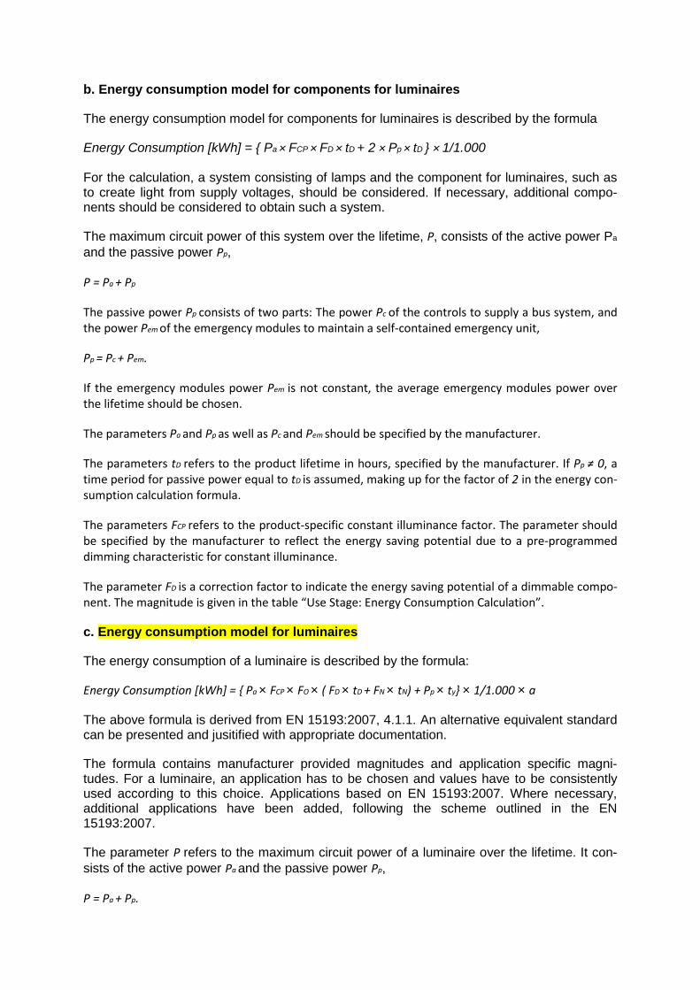
b. Energy consumption model for components for luminaires
The energy consumption model for components for luminaires is described by the formula
Energy Consumption [kWh] = { Pa × FCP × FD × tD + 2 × Pp × tD } × 1/1.000
For the calculation, a system consisting of lamps and the component for luminaires, such as to create light from supply voltages, should be considered. If necessary, additional compo-nents should be considered to obtain such a system.
The maximum circuit power of this system over the lifetime, P, consists of the active power Pa
and the passive power Pp,
P = Pa + Pp
The passive power Pp consists of two parts: The power Pc of the controls to supply a bus system, and the power Pem of the emergency modules to maintain a self-contained emergency unit,
Pp = Pc + Pem.
If the emergency modules power Pem is not constant, the average emergency modules power over the lifetime should be chosen.
The parameters Pa and Pp as well as Pc and Pem should be specified by the manufacturer.
The parameters tD refers to the product lifetime in hours, specified by the manufacturer. If Pp ≠ 0, a time period for passive power equal to tD is assumed, making up for the factor of 2 in the energy con-sumption calculation formula.
The parameters FCP refers to the product-specific constant illuminance factor. The parameter should be specified by the manufacturer to reflect the energy saving potential due to a pre-programmed dimming characteristic for constant illuminance.
The parameter FD is a correction factor to indicate the energy saving potential of a dimmable compo-nent. The magnitude is given in the table “Use Stage: Energy Consumption Calculation”.
c. Energy consumption model for luminaires
The energy consumption of a luminaire is described by the formula:
Energy Consumption [kWh] = { Pa × FCP × FO × ( FD × tD + FN × tN) + Pp × ty} × 1/1.000 × a
The above formula is derived from EN 15193:2007, 4.1.1. An alternative equivalent standard can be presented and jusitified with appropriate documentation.
The formula contains manufacturer provided magnitudes and application specific magni-tudes. For a luminaire, an application has to be chosen and values have to be consistently used according to this choice. Applications based on EN 15193:2007. Where necessary, additional applications have been added, following the scheme outlined in the EN 15193:2007.
The parameter P refers to the maximum circuit power of a luminaire over the lifetime. It con-sists of the active power Pa and the passive power Pp,
P = Pa + Pp.

43
Product Category Rules for Construction Products, Part A
The passive power Pp consists of two parts: The power Pc of the controls to supply a bus sys-tem, and the power Pem of the emergency modules to maintain a self contained emergency unit,
Pp = Pc + Pem.
The figures Pa , Pp , Pc and Pem should be specified by the manufacturer as described in the previous sections a. Energy consumption model for lamps and b. Energy consumption model for components for luminaires.
The parameters tD and tN refer to daylight and non‐daylight time usage. The respective magni-tudes are application specific. Magnitudes are specified in EN 15193:2007. The parameter ty
is the standard year time (8760 hours).
The parameters FO and FD refer to the occupancy dependency factor and the daylight depend-ency factor. These parameters are application specific. FD reflects the energy saving potential of a dimmable luminaire due to dimming during daylight operating hours. FO reflects the ener-gy saving potential due to a built‐in presence detector. The respective application specific values are given in EN 15193:2007.
The parameters FCP refers to the product specific constant illuminance factor. The parameter should be specified by the manufacturer to reflect the energy saving potential due to a pre‐programmed dimming characteristic for constant illuminance. The parameters FCP is a prod-uct‐specific substitute for the application‐specific constant illuminance factor FC as described in the EN 15193:2007. The substitution is necessary to obtain product specific results.
The parameter FN refers to the non‐daylight dimming factor. It reflects the energy saving po-tential of luminaires during non‐daylight hours. This factor does not have an influence on the applications originally specified in EN 15193:2007.
The parameter a is the application specific empiric lifetime of the luminaire given in years.The magnitudes for the respective applications are summarized in the table “Use Stage: Energy Consumption Calculation”.
If none of the predefined use stage scenarios is applicable, a representative scenario should be created following the indicated scheme. The scenario should be unambiguously docu-mented.
All manufacturer specific data has to be documented.
Ceramic materials
Plastic and elastomer sheeting
Lightweight concrete
Light additives / Bulk granulate
Metal installation pipes
→ Depending on the type of metal, purity of metal scrap and/or the requirements on pu-rity of the recycled metal, the substitution point before or after remelting the scrap can be applied for calculating the substitution potential in Module D. When using copper in the construction industry, it can generally be assumed that pure copper scrap directly substitutes (primary) copper cathodes.

44 Product Category Rules for Construction Products, Part A
Mineral insulating materials
Mineral mortar
→ When using the sample Environment Product Declarations (sample EPDs) of the In-dustrieverband Werkmörtel e.V. (IWM) for masonry mortar, plaster mortar or screed mortar, compliance with the respective mixture range applied and the calculations of the Life Cycle Assessment parameters based on that is ensured with the aid of an evaluation system within the framework of the appropriate instructions.
→ It is permissible to use the averaged data representative for the respective country in the case of sand, cement, limestone / lime hydrate, gypsum/anhydrite, filling agents, light additives and any ancillary materials, additives and water used. Alternatively, average data or specific data can be used for the corresponding end product; the se-lected approach must be documented. In the case of standard and standardised mix-tures, average data suffices; in the case of mixtures subject to approval in Germany, the mixtures filed at the Deutsches Institut für Bautechnik (DIBt) must be used.
Mineral panels
Aerated concrete
Sanitary fittings and showers
The following formula serves as a basis for calculating the usage scenario for the described product and its application (according to the NWO 10-14 Profile on drinking water require-ments and waste water output of the DGNB Building Certification – New Buildings - Residen-tial Buildings) However, an alternative equivalent standard can be presented and jusitified with appropriate documentation as well as country household statistics by the relevant Federal Agency.
wbI = (nNU * fI * asI * 345 d/a)/1000
with:
wbI Specific drinking water consumption of the installation in m³/a
nNU Number of users
fI Installation-specific (application-specific) factor for water consumption as per Table 1 in sec/d or flushes/d
asI Installation-specific connection value in l/sec or l/flush
The number of users is calculated in Profile 14 according to the area of the building. In the event of a declared product, average household size in Germany is assumed:
2.05 users per household according to the Federal Statistics Agency
The installation-specific factors are adopted from Profile 14 and listed in the following table:
Table 1: Water consumption values for various fittings
Installation Installation-specific factor fI for water con-sumption (sec or flushes per person and

45
Product Category Rules for Construction Products, Part A
day)
Washbasin 120
WC economy button
4
WC 1
Bathtub 180
Shower 120
The installation-specific connection value corresponds with the flow rate of the declared product.
Based on DIN 18599 Part 8 (Energy performance of buildings – Calculation of the net, final and primary energy demand for heating, cooling, ventilation, hot water and lighting – Part 8: Net and final energy demand for water heating systems), the net energy demand for hot wa-ter can be calculated in kWh/a for the application described in the Declaration. An alternative equivalent standard for net energy demand can be presented and justified with appropriate documentation.
Q = ρ *c * V * 345d/a* nNU * (θm - θk)
with:
Q Net energy demand for hot water in kWh/a
Ρ Density of water in kg/l
C Specific heat capacity (1.163*10-3 kWh/kg*K)
V Volume of water in l/person and day (the water volume is cal-culated from the fitting flow rate and the installation-specific factors for the respective fitting (see Table 1))
nNU Number of users
Θm Average tapping temperature in °C (50 °C) (average tempera-ture of the drinking water network (with circulation line and/or additional electric heating) and the tank as per DIN 18599, Part 8)
θk Cold water inlet temperature in °C (10 °C) (standard as per DIN 18599, Part 8)
46 Product Category Rules for Construction Products, Part A
As a rule, the following Ökobau.dat low-temperature gas boiler must be used for establishing the net energy demand in the basic scenario, unless an alternative equivalent standard can be presented and jusitified with appropriate documentation.:
8.6.1_Nutzung_-_Gas_Niedertemperatur_20-120_kW
Additional scenarios for establishing the net energy demand are permissible.
Foam plastics
Laminates
Locks and fittings
Solid wood products
→ Where glued products are involved, the mix of adhesives available on the market (for group EPDs) or specific data can be used for calculation purposes. The approach selected must be documented. In the case of non-glued bonds, the binding method must be declared in the EPD.
→ The resource aspect of wood must be balanced via the features inherent as a mate-rial as a CO2 resource point from the atmosphere and the lower calorific value as consumption of renewable energy carriers.
Synthetic yarns
Dyes and Pigments:
As for the commonly used dyes for coloration of yarns no LCA data are available, alternative-ly, proceed as follows (see also GUT’s Life cycle assessment study on textile floor cover-ings):
- As a substitute for inorganic pigments, the equivalent amount of TiO2 is used.
- As a substitute for organic pigments the equivalent amount of soot (technically) is used.
- As a replacement substance for dyes, that are applied with aqueous dyeing process, the equivalent amount of anthraquinone is used.
- for yarns that are dyed after the mechanical processing (tufting or weaving), the amount of TiO2, which is used as a matting agent has to be considered.
- As a measure for the required amount of dyestuff, the amount of dyestuff required to achieve a "medium-gray color tone" (in a trichromatic color system) has to be used.
Upstream processes
The following preliminary processes have to be considered as a minimum:
- Production and transport of the polymer granules
- Production and transport of additives and excipients
- Production and transport of packaging materials
For purposes of mutual recognition under ULE and IBU, the following will apply:

47
Product Category Rules for Construction Products, Part A
- If available, appropriate data sets (from GaBi about 4 or 5) are used.
Note: If no (manufacturer) specific data set for the PA-6 production is available, a mixed da-ta set consisting of 50% Gabi record DE: PA 6 (caprolactam via cyclohexane) and 50% of NL: PA 6 (caprolactam via phenol-route) has to be used instead. The Plastics Europe data set for PA 6 is currently under revision and should no longer be used until an updated data set is published.
For all others polymers used in the manufacture of carpet yarns specific data sets should be used where possible. If no specific data sets are available, "Plastics Europe" data sets can be used instead. Appropriate information on the update scenario for these data sets should be respected.
Manufacturing process
The manufacturing process includes:
- Extruding and spinning of filaments
- All the necessary finishing processes (air-entangling, fixation and Heat Setting etc)
- all coloring processes (Note: in the case of undyed yarns, the coloring process of the carpet has to modeled as part of manufacturing process).
- Production and transport of all excipients used for this purpose
- Any other relevant input and output flows (energy, waste water, emissions into the envi-ronment, etc.) are taken into account.
- The manufacturing process ends with the packaging of the yarn in delivery ready state. If yarns are delivered on reusable yarn carriers, it has to be mentioned.
Downstream processes
Transport to the customer, the use stage and the 'end-of-life' are not considered, since this can only be defined in connection with the manufacturing process of the textile floor covering. If special means for transport are available, this can be specified. Otherwise truck transport is assumed to the customers and is considered in the preparation of the carpet-EPD.
Results
The balanced results for the modules A1, A2 and A3 should be reported separately. Where it can be shown that this, due to lack of data (preliminary) is not possible, an aggregation of individual results (A1-A3) is possible.
Composite heat insulation systems
Bricks

48 Product Category Rules for Construction Products, Part A