processing and characterization of niti porous...
TRANSCRIPT

1
Processing and Characterization of NiTi Porous SMA by Elevated Pressure Sintering
a,bDimitris C. Lagoudas and aEric L. Vandygriff
aCenter for Mechanics and Composites
Aerospace Engineering Department, Texas A&M University College Station, TX 77843-3141
email: [email protected]
o: (979) 845-1604 fax: (979) 845-6051
ABSTRACT Currently, three methods are commonly used for producing porous NiTi
shape memory alloys (SMAs) from elemental powders. These include conventional sintering, Self-propagating High temperature Synthesis (SHS), and sintering at elevated pressure via a Hot Isostatic Press (HIP). Conventional sintering requires long heating times and samples are limited in shape and pore size. SHS is initiated by a thermal explosion ignited at one end of the specimen, which then propagates through the specimen in a self-sustaining manner. One of the difficulties with SHS is the inability to control intermetallic phases. This work will focus on the fabrication and characterization of porous NiTi SMA material produced from elemental powders via HIPping.
Porous NiTi SMA was produced from elemental Ni and Ti powders at elevated temperature and pressure using a Hot Isostatic Press (HIP). Small and large pore specimens containing average pore sizes ranging from 20 microns up to 1mm have been produced by slightly varying the HIPping sintering temperatures and times.
Quasi-static and dynamic loading experiments are conducted on various samples produced using the presented methodology and their shape recovery and energy absorption characteristics are measured during the forward and reverse phase transformation and detwinning. Their phase transformation characteristics were found using calorimetric measurements and their composition has been studied using optical and electron microscopy and microprobe x-ray analysis.
Keywords: porous, shape memory alloy, NiTi, powder metallurgy, sintering, quasi-static loading, impact loading, HIP, Self-propagating High temperature Synthesis
INTRODUCTION
As the requirements for many engineering applications tend toward a more compact and durable structure, Shape Memory Alloys (SMAs) are becoming a common ground as a multifunctional material, able to provide structural support as well as offer possibilities of actuation due to their ability to be deformed and return

2
to a memorized shape. Over the last two decades, extensive studies have been completed which promote the use of SMAs in various engineering fields including a wide range of applications from naval functions, including underwater silent propulsion (Garner et al., 2000), to aviation (Jardine, 1996) and aerospace applications (Yiu and Regelbrugge, 1995). SMAs are also quickly finding their place in the medical field as medical devices, tools, implants and fixtures (Haasters, Bensmann, and Pon 1986; Thier, 1990). These applications have mostly benefited from the ability of the inherent shape recovery characteristics exhibited by SMAs (Wayman, 1983; Funakubo, 1987; Duerig and Pelton, 1994; Fremond and Miyazaki, 1996). In addition to the shape memory and pseudoelasticity effects that SMAs possess (Otsuka and Wayman, 1998; Martynow, Skorohod and Solonin, 1991), there is also the promise of using SMAs in making high-efficiency damping devices (Wolons, Gandhi and Malovrh, 1998) that are superior to those made of conventional materials, partially due to their hysteretic response.
Due to the ability of SMAs to repeatedly withstand relatively large recoverable strains coupled with their inherent large hysteretic response and variable stiffness, research is being conducted to investigate the use of SMAs as damping devices and impact absorbing components (Yiu and Regelbrugge, 1995; Thompson, Balas and Leo, 1995; Fosdick and Ketema, 1998; Turner, 2000; Wilde, Gardoni and Fujino, 2000; Chen and Lagoudas, 2000). Encouraged by the pursuit of these more advanced materials, the focus of the engineering community has given recent attention to the fabrication of porous SMAs (Yi and Moore, 1990; Hey and Jardine, 1994; Li, Rong and Li, 1994; Tangaraj et al., 2000; Vandygriff et al., 2000). Even beyond the energy absorption capabilities offered by conventional SMAs, porous SMAs offer the possibility of higher specific energy damping capacity under dynamic loading conditions and the possibility of wave scattering. With the additional possibility of grading the porosity, porous SMAs could also be designed for impedance matching at connecting joints with other structural materials as well. Depending on the necessity of the application, porous SMAs could be manufactured with open or closed pore designs. Open porous SMAs are already beginning to find their way into biomedical applications as implants for bone reconstruction due to their permeability and reduced density (Simske, Ayers and Bateman, 1996; Ayers et al., 1999).
Various methods for producing conventional porous metals and alloys currently exist, including casting, metallic deposition, and powder metallurgy (Davies and Zhen, 1983). One casting technique commonly used for producing metal foams includes the injection of gas into a metal melt, as described by Gibson and Ashby (1999). Other methods employ powder metallurgy techniques including conventional sintering, Self-propagating High-temperature Synthesis (SHS), and sintering at elevated pressure using a Hot Isostatic Press (HIP).
Of the many SMAs available, NiTi has become one of the most widely used of the shape memory alloys due to its exceptional physical and mechanical properties, including large recoverable strains in polycrystalline forms (Hodgson and Brown, 2000). This research effort will investigate the fabrication of porous NiTi. Due to the high melting temperature (1310°C) and relatively high density of NiTi (6.45 g/cm3), fabrication challenges of injecting a gas into a NiTi melt are introduced that are not typically present with many other metal foams like aluminum. Also, conventional fabrication techniques of casting NiTi from a melt

3
can be difficult due to the reactivity of the melt that often results in segregation defects (Hey and Jardine, 1994). These difficulties have influenced the authors to utilize powder metallurgy techniques to produce porous NiTi SMA. Powder metallurgy offers the opportunity of employing either elemental or pre-alloyed starting powders. However, additional processing techniques required for producing pre-alloyed NiTi powders are both difficult and expensive. For this reason, this research effort will focus on fabrication of binary NiTi SMAs from elemental powders using the powder metallurgy techniques referred to above.
Conventional sintering has proven to be a viable method of producing porous NiTi SMA (Li, Rong and Li, 1998). A cold compact of Ni and Ti powders are pressed from an elemental powder mixture to form a pellet compact, which is then sintered at near melting temperatures to produce a binary NiTi phase through diffusion of the two elements (Tangaraj, Chen and Salama, 2000). Using this method, porosity of the specimen is varied by the powder compaction pressure and the initial powder size and shape. Because the porosity results directly from the voids left between powder particles, the average pore size is relatively small and the overall pore volume is limited to a maximum porosity of nearly 40%. Some disadvantages associated with conventional sintering include long heating times (48 hours), small specimen sizes, and difficulties associated with other stable intermetallic phases.
Self-propagating high-temperature synthesis, or combustion synthesis, has also been successful in the fabrication of porous SMAs from elemental powders (Yi and Moore, 1990; Li, Qui and Liu, 1992). Combustion synthesis causes the solids to dissolve by introducing a liquid phase to promote the kinetics of mass transfer. Due to the exothermic reaction of Ni with Ti, the process is initiated by heating the entire specimen until reaction occurs or by a thermal explosion ignited at one end of the specimen, which then propagates through the specimen in a self-sustaining manner. Combustion synthesis has been successful in producing porous SMA with porosity counts as high as 65%. However, due to the explosive nature of the exothermic reaction through combustion synthesis, experimental control is limited once the reaction has initiated. Rapid heating rates and short heating times also make for a less consistent material due to the lack of particle diffusion and the formation of precipitates (Hey and Jardine, 1994). Also, the success of SHS is greatly dependent on the shape of the canister for a thorough reaction to occur.
Another method for producing metal foams from powders via a HIP was recently implemented by Kearns (1988). This work was later expanded on by Schwartz (1998) and then by Davis et al. (2001). This technique utilizes a HIP to compress and trap Ar gas bubbles between neighboring metal powders. The resulting compact contains high pressure Ar pores that became trapped between the metal powders during high-pressure diffusion. Subsequent sintering at reduced pressure causes the trapped gas to expand in the high temperature softened material. This method has been successful in producing components with relative densities as low as 50%.
Based on the HIPping technique, porous NiTi SMA was recently produced from elemental Ni and Ti powders in the Active Materials and Structures Laboratory at Texas A&M University (Lagoudas et al., 2001; Vandygriff et al., 2000). Some advantages of producing porous NiTi via HIPping include: 1) decreased solid state diffusion time, 2) control of pore size and volume fraction,

4
3) the ability to produce a variety of shapes, decreasing necessary machining time, and 4) a more stable and controllable reaction than offered by SHS. Some of the difficulties that may be encountered with the use of elemental powders to fabricate NiTi via HIPping are similar to those encountered using conventional sintering and include contamination from oxides and the formation of other stable intermetallics. Using the HIP method, several NiTi specimens are fabricated with porosity levels ranging from 40-50% and tested under quasi-static and dynamic loading conditions. This research effort will utilize the HIP technique to fabricate two different types of specimens: small and large pore specimens.
In the following sections, this paper will describe two different HIPping techniques used to fabricate small and large pore NiTi SMA from elemental Ni and Ti powders via HIPping. Phase Transformation characteristics and material composition of HIPped porous NiTi will be addressed by results from thermal and material analysis techniques. The possibility of employing HIPped porous NiTi as single-component multifunctional shape memory and energy absorption devices (providing both structural stiffness and damping characteristics) will be demonstrated from results of quasi-static and dynamic tests performed under compression. The damage and failure characteristics of the porous SMAs will also be briefly described.
FABRICATION AND CHARACTERIZATION OF HIPped POROUS NITI Fabrication of HIPped Porous NiTi
Elemental Ni and Ti powders obtained from Micron Metals Inc. are mixed together with a ratio of 50.6 at.% Ni (McNeese, Lagoudas, and Pollock, 2000) and loosely packed into a stainless steel canister. The loosely packed powders have a relative density of approximately 50%. The canister is then capped (not an air tight seal) and placed into the HIP machine, vacuum purged, then backfilled with ultra high purity Ar, which is then heated and pressurized to 200MPa via the HIP. During the HIPping process the temperature is raised to a minimum sintering temperature of 940ºC and the pressure is increased to 200MPa. NiTi is created as a result of diffusion of Ni and Ti species. By maintaining a temperature below the melting point, compressed Ar gas remains between the diffused alloy. A sintering temperature above the melting temperature of NiTi would result in a melt in which the Ar bubbles would escape to the top of the melt. To promote diffusion, Ni and Ti particle sizes of <20 microns and 99.9% pure are employed. While in the HIP, the pressure is decreased, allowing pressurized argon pores to expand in the still soft NiTi medium (Figure 1). In previous attempts by Kearns, Schwartz, and Davis to create porous metals from HIPping, a sealed canister design is employed in which the pore expansion is primarily carried out in the post-annealing process, whereas in this experimental effort, the greater part of the pore expansion is completed during the HIP cycle. After HIPping, the specimen is annealed in a furnace at 900ºC for 6 hours to facilitate further diffusion of the elements and to enhance the porosity of the material. Through slight variations in the HIPping temperature and sintering time, specimens with relatively small and large pores are produced.

5
Figure 1: HIP cycle for fabricating porous NiTi SMA from elemental Ni and Ti powder
(large pore specimen)
To produce porous NiTi specimens with relatively small pores, the HIPping
temperature is initially raised to 940ºC at 1MPa for 40 min to initiate diffusion. Next, the pressure is raised to 200MPa for 6 hours as solid-state diffusion continues between the species. The temperature and pressure are then decreased and the specimen is removed from the HIP and annealed in a conventional furnace at 900ºC in Ar for an additional 6 hours. The small pore specimens have an average pore size of approximately 20µm and an open pore structure. Microscopic observations of the characteristic size and shape of the pores suggest that the pores are formed from voids left as a result of the spacing between the initial powders (similar to conventional sintering). Expansion of these voids upon decreasing the pressure may assist in the increase of the overall pore volume fraction if Ar has become trapped during the high-pressure diffusion, but is not the primary contributor to the overall relative density. This method has been successful in producing porous NiTi with relative densities as low as 50%. The porosity is calculated by comparing the measured density of the porous NiTi to the theoretical density of solid NiTi (6.45 g/cm3). Micrographs of the small pore specimens are shown in Figure 3 (a and b).
For producing porous NiTi with relatively large pores, the HIPping temperature is initially raised to 940ºC at 1 MPa to promote initial diffusion between the powders (Figure 2, part 1 and 2). Next, the temperature and pressure are then simultaneously increased to 1000ºC and 200MPa. As the pressure increases, the increasing temperature exceeds the eutectic and peritectic temperature of NiTi2 (942ºC and 984ºC) and approaches the melting point of Ni3Ti (1118ºC), causing partial melting of the diffusing powder mixture at sintering temperatures below the melting temperature of binary NiTi (Massalski, 1986). As this occurs, open pores containing high pressure Ar begin to close, trapping the Ar in the diffusing medium. Continued increases in pressure cause these now closed
0
200
400
600
800
1000
1200
0.0 0.6 1.2 1.8 2.4 3.0
Time (Hrs)
Tem
per
ature
(C)
0
50
100
150
200
250
Pre
ssure
(MPa)
Temperature (C)
Pressure (MPa)
11
66
55443322
Time (hrs)
Tem
pera
ture
(C)
Pres
sure
(M
Pa)

6
pores to decrease in volume, promoting enhanced diffusion (Figure 2, part 3, 4, and 5). This process causes a decrease in the overall volume of the initially 50% porous mixture, creating a closed pore microstructure with relatively high-pressure argon pores. At 1000ºC and 200MPa, the consolidated medium is then annealed for 2.5 hours (Figure 2, part 5). After 2.5 hours, the temperature and pressure are then decreased simultaneously, allowing the compressed argon pores to expand in the still soft NiTi medium (Figure 2, part 6). After completing the HIPping cycle, the specimen is then heated in a conventional furnace in Ar for 6 hours at 900ºC to facilitate further diffusion of the elements and enhance the porosity of the material. This method has been successful in producing porous NiTi with porosity counts as high as 42%. A simplified schematic of the pore evolution using this technique is shown in Figure 2. The encircled numbers in Figure 2 correspond to the various HIPping stages seen in Figure 1. Observation of the size and characteristic shapes of the pores in the large pore NiTi specimens suggest that unlike the smaller pore specimens, the large pores are formed mostly upon the expansion of the Ar when the pressure is decreased. As the pores expand, many join, causing the formation of channel-like pores (Figure 3, c and d). It can also be seen in Figure 3 (c and d) that many pores formed without joining. These two types of pore formations result in a mostly open pore structure interlaced with smaller closed pores.
Figure 2: Pore evolution of large pore NiTi using a HIP
Nickel Powder
Titanium Powder
1 2 3 4 5 6
Temp:
Pressure:
Nickel Powder
Titanium Powder
11 22 33 44 55 66
Temp:
Pressure:

7
Figure 3: Micrographs of HIPped porous NiTi: (a) small pore 10x; (b) small pore 50x;
(c) large pore transverse cut; (d) large pore axial cut. Material Characterization and Identification of Phase Transformation of HIPped Porous NiTi
Next, a thermal scan was conducted on the HIPped porous SMA specimens
using a Perkin Elmer Pyris 1 Differential Scanning Calorimeter (DSC). The upper curves seen in Figure 4 represent the normalized heat flow (W/g) into the specimen during heating and the lower curves represent the heat flow out of the specimen upon cooling. The tests indicate diffusionless solid-solid phase transformation at approximately 43ºC and 42ºC (measured at transformation peaks) during heating (martensite-to-austenite) and –12ºC and 20ºC (measured at transformation peaks) during cooling (austenite-to-martensite) for the small and large pore specimens, respectively. Therefore, depending on whether the specimen was previously heated or cooled, either the martensite or austenite crystalline structure can be present at room temperature (22ºC). Note that for the small pore specimen the first peak encountered upon cooling is indicative of an R-phase transformation (Wu and Wayman, 1989).
NiTi
Pores a) b)
d) c)

8
Figure 4: Thermal scan of porous NiTi: (a) DSC results of small pore specimen; (b) DSC
results of large pore specimen. In addition to the thermal analysis, further investigations to verify the
composition of the porous specimens were conducted using a microprobe. A Cameca SX50 Electron Microprobe was used to verify the material of the porous specimens created from the HIPping process. By employing the electron backscattering capabilities of the microprobe, evidence of multiple intermetallic phases was revealed (Figures 5a and 7a) in the small and large pore specimens. However, evidence of different phases was most prominent in the small pore specimens, with some of the phases occurring in areas as large as 20 microns. Next, a preliminary scan for elements was conducted on both types of specimens using an Energy-Dispersive X-ray Spectrometer (EDS). The results are shown in Figure 5b and 7b for the small and large pore specimens, respectively. The EDS shows no evidence of elements other than Ni and Ti, except that of carbon in the small pore specimen from the epoxy casting that was used to mount and polish the specimens.
Further analysis of the small and large pore specimens using a Wave-Dispersive X-ray Spectrometer (WDS) was conducted on each phase seen in the backscattered electron (BSE) image for quantitative results. In the small pore
a)
b)
9
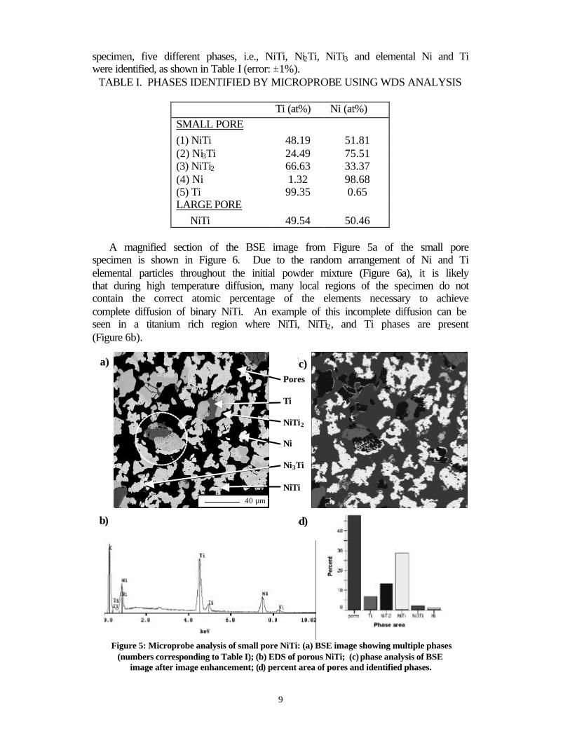
specimen, five different phases, i.e., NiTi, Ni2Ti, NiTi3 and elemental Ni and Ti were identified, as shown in Table I (error: ±1%).
TABLE I. PHASES IDENTIFIED BY MICROPROBE USING WDS ANALYSIS
Ti (at%) Ni (at%) SMALL PORE (1) NiTi 48.19 51.81 (2) Ni3Ti 24.49 75.51 (3) NiTi2 66.63 33.37 (4) Ni 1.32 98.68 (5) Ti 99.35 0.65 LARGE PORE NiTi 49.54 50.46
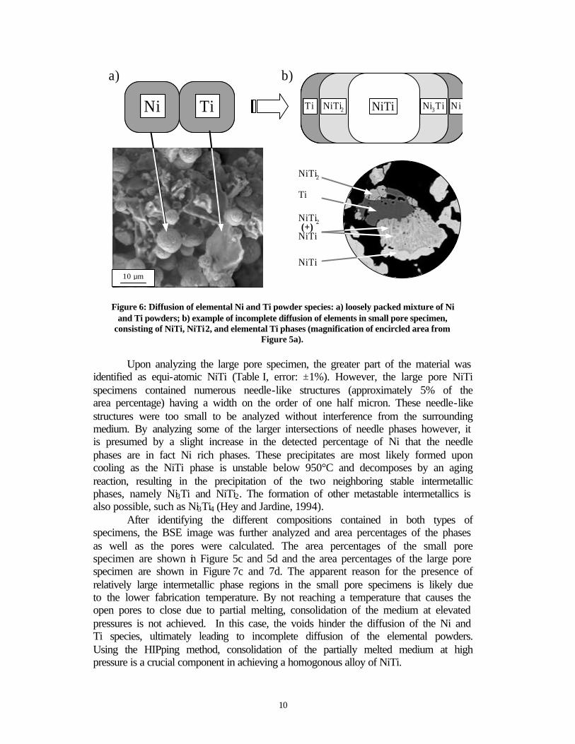
A magnified section of the BSE image from Figure 5a of the small pore
specimen is shown in Figure 6. Due to the random arrangement of Ni and Ti elemental particles throughout the initial powder mixture (Figure 6a), it is likely that during high temperature diffusion, many local regions of the specimen do not contain the correct atomic percentage of the elements necessary to achieve complete diffusion of binary NiTi. An example of this incomplete diffusion can be seen in a titanium rich region where NiTi, NiTi2, and Ti phases are present (Figure 6b).
Figure 5: Microprobe analysis of small pore NiTi: (a) BSE image showing multiple phases (numbers corresponding to Table I); (b) EDS of porous NiTi; (c) phase analysis of BSE
image after image enhancement; (d) percent area of pores and identified phases.
a) b)
d)c)b) d)
c)
40 µm
Pores Ti NiTi2 Ni Ni3Ti NiTi
10
Figure 6: Diffusion of elemental Ni and Ti powder species: a) loosely packed mixture of Ni
and Ti powders; b) example of incomplete diffusion of elements in small pore specimen, consisting of NiTi, NiTi2, and elemental Ti phases (magnification of encircled area from
Figure 5a).
Upon analyzing the large pore specimen, the greater part of the material was identified as equi-atomic NiTi (Table I, error: ±1%). However, the large pore NiTi specimens contained numerous needle-like structures (approximately 5% of the area percentage) having a width on the order of one half micron. These needle-like structures were too small to be analyzed without interference from the surrounding medium. By analyzing some of the larger intersections of needle phases however, it is presumed by a slight increase in the detected percentage of Ni that the needle phases are in fact Ni rich phases. These precipitates are most likely formed upon cooling as the NiTi phase is unstable below 950°C and decomposes by an aging reaction, resulting in the precipitation of the two neighboring stable intermetallic phases, namely Ni3Ti and NiTi2. The formation of other metastable intermetallics is also possible, such as Ni3Ti4 (Hey and Jardine, 1994).
After identifying the different compositions contained in both types of specimens, the BSE image was further analyzed and area percentages of the phases as well as the pores were calculated. The area percentages of the small pore specimen are shown in Figure 5c and 5d and the area percentages of the large pore specimen are shown in Figure 7c and 7d. The apparent reason for the presence of relatively large intermetallic phase regions in the small pore specimens is likely due to the lower fabrication temperature. By not reaching a temperature that causes the open pores to close due to partial melting, consolidation of the medium at elevated pressures is not achieved. In this case, the voids hinder the diffusion of the Ni and Ti species, ultimately leading to incomplete diffusion of the elemental powders. Using the HIPping method, consolidation of the partially melted medium at high pressure is a crucial component in achieving a homogonous alloy of NiTi.
NiTi Ni3TiNiTi2 NiTi NiTi Ni3TiNiTi2 NiTiNi TiNi Ti
NiTi2
Ti
NiTi2 (+)
NiTi
NiTi
a) b)
10 µm

11
Figure 7: Microprobe analysis of large pore NiTi: (a) BSE image showing phases; (b) EDS of porous NiTi; (c) phase analysis of BSE image after image enhancement; (d) percent area of
pores and identified phases.
Quasi-Static and Dynamic Testing of HIPped Porous NiTi under Compressive Loading Pseudoelastic Testing of Porous NiTi Under Uniaxial Quasi-static Loading
Mechanical testing was conducted on both small and large pore NiTi
specimens. Both types of specimens were tested under compressive loads in quasi-static conditions using flat compression plates. The specimens were cylindrical and had a diameter of 13mm and were 33mm long. An MTS hydraulic load frame was used to apply load by displacement control and a resistive oven was used to elevate the temperature of the test section. For strain measurement, an extensometer with a 25mm gauge length was used. The tests were performed at a temperature of 60ºC, just slightly above austenite finish temperature (Af) for both specimens (see Figure 4). Each specimen was subjected to cyclic mechanical loading with an increasing magnitude of the maximum strain applied to each cycle. Note that all of the mechanical tests performed for this study were under compression, therefore, compressive strain will be represented by positive values.
Representative results for two specimens with the small and large pores are shown in Figures 8 and 9. It can be seen that after some initial elastic response,
Perc
ent
Phase Area
a)
c)
b)
d)c)
b)
d)
a)
Perc
ent
Phase Area
a)
c)
b)
d)c)
b)
d)
a) c)
d) b)
a)
200 µm
12
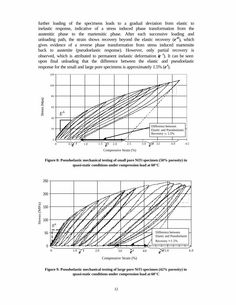
further loading of the specimens leads to a gradual deviation from elastic to inelastic response, indicative of a stress induced phase transformation from the austenitic phase to the martensitic phase. After each successive loading and unloading path, the strain shows recovery beyond the elastic recovery (ε el), which gives evidence of a reverse phase transformation from stress induced martensite back to austenite (pseudoelastic response). However, only partial recovery is observed, which is attributed to permanent inelastic deformation (ε i). It can be seen upon final unloading that the difference between the elastic and pseudoelastic response for the small and large pore specimens is approximately 1.5% (ε t).
Figure 8: Pseudoelastic mechanical testing of small pore NiTi specimen (50% porosity) in
quasi-static conditions under compression load at 60°C
Figure 9: Pseudoelastic mechanical testing of large pore NiTi specimen (42% porosity) in
quasi-static conditions under compression load at 60°C
Stre
ss (M
pa)
0
20
40
60
80
100
120
0
20
40
60
80
100
120
Difference between Elastic and Pseudoelastic Recovery ≈ 1.5%
Compressive Strain (%)
0.5 1.5 1.0 2.5 3.0 4.0 4.5 2.0 3.5 0
EA
EM
EA
ε t ε el ε i
1.0 3.0 2.0 4.0 5.0 6.0
Compressive Strain (%)
0
50
100
150
200
250
Str
ess
(MP
a)
Difference between Elastic and Pseudoelastic Recovery ≈1.5%
0
EA
EM
ε t ε el ε i

13
It can be seen from Figures 8 and 9 that the quasi-static results for the
porous NiTi differ from a typical stress-strain response of dense NiTi. The stress induced martensite transformation in dense NiTi occurs throughout the entire medium at nearly the same stress level, commonly resulting in easily identifiable regions of phase transformations in stress-strain data charts (Miyazaki et al., 1986; Kato, 1993). In the porous NiTi samples however, a gradual change in the tangent stiffness beyond the elastic limit can be seen in Figures 8 and 9, indicating a gradual transformation of regions of austenite into stress induced martensite.
The elastic stiffness of the austenite and martensite regions are very different in the two specimens. The elastic stiffness of the austenitic phase ( AE ) in the large pore specimens is approximately 15GPa (Figure 9), about twice that of the elastic stiffness of the small pore austenitic phase of 7GPa (Figure 8). This difference in stiffness may be partially due to the incomplete diffusion of the powders in the small pore specimen and the resulting partial adherence of the powder particles, as indicated by the microprobe analysis. The difference in the pore volume fraction of the two types of specimens also contributes to the difference in the observed initial elastic stiffness. Note that for both cases, the low value of the initial elastic stiffness may result from geometric effects due to porosity.
Efforts to model the effective thermomechanical response of porous SMAs have been made by Lagoudas et al. (2001), Qidwai et al. (2001), and Entchev and Lagoudas (2001). In these works the mechanical quasi-static behavior of porous NiTi was modeled using a micromechanics averaging model and Unit Cell Finite Element Method (UCFEM). The micromechanics modeling shows results compatible with the experimental observations, i.e., a reduction of EA and the onset of stress induced martensite due to porosity. In addition, the UCFEM results show a gradual phase transformation due to local stress concentrations caused by the introduction of pores into the matrix, similar to the experimental results
The manner of failure of the large and small pore specimens was also noticeably different. The large pore specimens failed gradually and had a tendency to form microcracks and cracking could be heard as the specimen was strained beyond 5%. This gradual failure is identified on the stress-strain curve where the stress begins to decrease as the strain is increased (Figure 9). Micrographs showed that the cracks appeared throughout the specimen and did not propagate through more than just a few neighboring pore walls (Figure 10b). In contrast, the small pore specimens fail catastrophically when strained between 5% and 6%, forming large cracks that propagate throughout the specimen, causing the specimen to break into multiple fragments (Figure 10a).

14
The sudden and catastrophic failure of the small pore specimens may be due to multiple reasons. Firstly, some of the intermetallic and elemental phases identified using microprobe analysis embrittle the material. In the small pore specimen, almost 24% percent of the total phase area (including pores) of the specimen consisted of phases other than NiTi (see Figure 5d). In contrast, only about 5% of the large pore specimen consisted of phases other than NiTi. Secondly, the incomplete diffusion of the elemental powders in the small pore specimen and partial adherance of the powder particles also lead to decreased overall ductility of the porous material. Finally, the uniformity of the pore size observed in the small pore specimens, results in more evenly distributed stresses throughout the specimen. Thus, failure of a local region causes simultaneous failure of the neighboring regions and overall fracture of the specimen. On the other hand, due to the variety of pore sizes and shapes in the large pore specimens, failure of a local region in the specimen could cause the load to be redistributed to neighboring regions which have not been critically stressed, resulting in local containment of damage. Mechanical Testing Under Uniaxial Dynamic Loading
Small and large pore specimens were also mechanically tested in
compression under uniaxial dynamic loading conditions. However, due to the brittleness of the small pore NiTi, dynamic testing caused these specimens to crumble upon impact. For this reason, only dynamic loading results for large pore specimens have been obtained.
Four of the large pore specimens were dynamically tested under compression at Los Alamos National Laboratory using a Split-Hopkinson bar apparatus. The diameter of each of the cylindrical specimens was 13mm. Each was approximately 5.5mm long. Before testing, each of the specimens was heated to 80°C, well above Af, then allowed to cool to room temperature, remaining mostly in the austenite phase (Figure 4b). They were then tested at 22°C. This temperature is close to martensite start temperature, Ms. However, it can be seen from the DSC results that upon heating, some apparent transformation from martensite to austenite may in fact begin near 10°C, even though the bulk of the
Figure 10: SEM micrographs of fractured porous NiTi due to quasi-static loading:
(a) fragmented surface of small pore specimen; (b) microcracks in large pore specimen.
1 mm1 mm1 mm 150 µm150 µm150 µm150 µm a) b)

15
transformation occurs 20°C higher. This leads to a slight overlap of the austenite and martensite phase start temperatures (As and Ms). The results from the dynamic tests for the HIPped specimens can be seen in Figures 11 and 12.
Figure 11 shows four consecutive impact tests performed on the same specimen (reheated to 80°C between each test). A 127mm striker bar was used for the impact load with a maximum strain rate of 3300/sec. The condition of the specimen prior to loading was a mixture of austenite and twinned martensite as a result of the initial testing temperature being slightly below Ms (Figure 4b). Therefore, the first part of the stress-strain curves shown in Figure 11 corresponds to elastic loading of austenite and martensite, as well as detwinning of martensite, which progresses to a strain of about 4%. The first phase transformation to stress induced detwinned martensite initiates near a strain of 1% (Figure 11, region A). After this initial load plateau, a second plateau occurs near a strain of 6%, indicating further transformation to detwinned martensite and the formation of additional inelastic strains which could be attributed to plasticity in the SMA as well as possible damage (Figure 11, region B). Upon unloading, it can be seen that there is immediate partial shape recovery evident in the unloading path beyond the elastic response of approximately 2%. This is attributed to an increase in temperature above As of the specimen due to latent heat released upon transforming from austenite to martensite as well as energy dissipation due to plasticity and damage.
After reheating the specimen to 80°C after each cycle, there was additional strain recovered, indicating that the temperature increase caused by the latent heat due to phase transformation as well as plasticity and damage was not sufficient to promote complete transformation back to austenite. In addition, the amount of strain recovered by the specimens when heated to 80°C increased after each successive cycle. Note that the strain value is reset to zero for each cycle and the strain of each cycle is relative to the length of the specimen after reheating from the previous cycle. Adding the amount of unrecoverable inelastic deformation from each impact cycle that remained after reheating totals nearly 11% of the initial length. Further study of the stress-strain response reveals that the transformation from austenite to stress induced martensite, indicated by the first stress plateau (Figure 11, region A), also became more distinguishable as the impact cycles were repeated.

16
Figure 11. Dynamic stress-strain response of porous NiTi under impact loading: 1 specimen,
4 cycles, 22ºC (reheated to 80°C after each cycle)
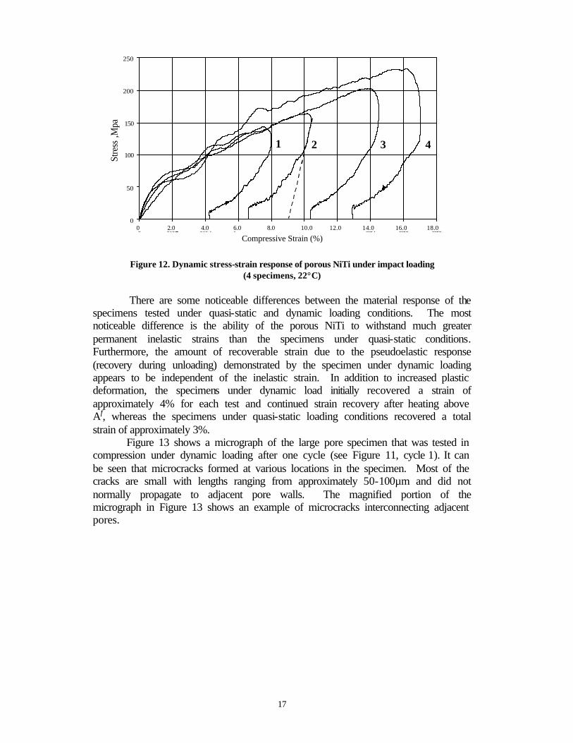
Figure 12 shows the results of the first cycle of four impact tests conducted on four different specimens tested to different maximum stress and strain levels. The maximum strain rate for the specimens was 2400/sec for the 127mm striker bar (Figure 12, specimens 1 and 2) and 3100/sec for the 250mm bar (Figure 11, specimens 3 and 4). The transformation stresses and strains are very similar to the transformation stresses and strains shown in Figure 11. Again, two distinct plateaus occur at nearly the same stress and strain levels. Also similar to the results in Figure 11, the shape recovery beyond the elastic response is measured to be 2%. One noticeable characteristic of the HIPped porous NiTi is the ability to undergo considerable inelastic deformation (overall strain of 17% of specimen 4) under dynamic conditions and exhibit similar amounts of recoverable strain upon unloading. The repeatability of the transformation curve is consistent, even after the specimens have undergone considerable inelastic strain. Again, partial shape recovery is seen upon unloading, contributed to the temperature increase caused by the latent heat released from the phase transformation as well as energy dissipation due to plasticity and damage.
0
20
40
60
80
100
120
140
160
180
0 0.02 0.04 0.06 0.08 0.1 0.12 0.14
Strain
Stre
ss, M
Pa
Spec1-Cycle 1Spec1-Cycle 2Spec1-Cycle 3Spec1-Cycle 4
B
A
Cycle 1
Cycle 2
Cycle 3, 4
Recovery upon heating to 80°C
2.0 4.0 6.0 8.0 10.0 12.0 14.0
Compressive Strain, %
17
Figure 12. Dynamic stress-strain response of porous NiTi under impact loading
(4 specimens, 22°C)
There are some noticeable differences between the material response of the specimens tested under quasi-static and dynamic loading conditions. The most noticeable difference is the ability of the porous NiTi to withstand much greater permanent inelastic strains than the specimens under quasi-static conditions. Furthermore, the amount of recoverable strain due to the pseudoelastic response (recovery during unloading) demonstrated by the specimen under dynamic loading appears to be independent of the inelastic strain. In addition to increased plastic deformation, the specimens under dynamic load initially recovered a strain of approximately 4% for each test and continued strain recovery after heating above Af, whereas the specimens under quasi-static loading conditions recovered a total strain of approximately 3%.
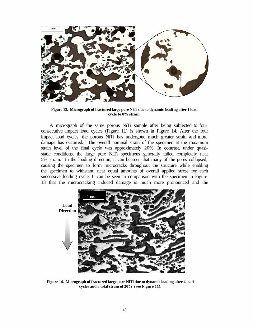
Figure 13 shows a micrograph of the large pore specimen that was tested in compression under dynamic loading after one cycle (see Figure 11, cycle 1). It can be seen that microcracks formed at various locations in the specimen. Most of the cracks are small with lengths ranging from approximately 50-100µm and did not normally propagate to adjacent pore walls. The magnified portion of the micrograph in Figure 13 shows an example of microcracks interconnecting adjacent pores.
0
50
100
150
200
250
0 0.02 0.04 0.06 0.08 0.1 0.12 0.14 0.16 0.18Strain
Stre
ss ,M
pa
0 2.0 4.0 6.0 8.0 10.0 12.0 14.0 16.0 18.0
Compressive Strain (%)
1 3 4 2
18
Figure 13. Micrograph of fractured large pore NiTi due to dynamic loadi ng after 1 load
cycle to 8% strain.
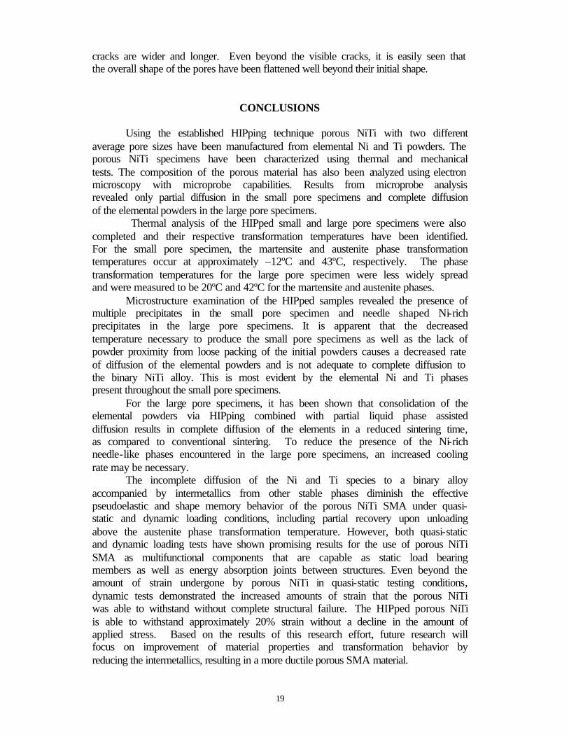
A micrograph of the same porous NiTi sample after being subjected to four consecutive impact load cycles (Figure 11) is shown in Figure 14. After the four impact load cycles, the porous NiTi has undergone much greater strain and more damage has occurred. The overall nominal strain of the specimen at the maximum strain level of the final cycle was approximately 20%. In contrast, under quasi-static conditions, the large pore NiTi specimens generally failed completely near 5% strain. In the loading direction, it can be seen that many of the pores collapsed, causing the specimen to form microcracks throughout the structure while enabling the specimen to withstand near equal amounts of overall applied stress for each successive loading cycle. It can be seen in comparison with the specimen in Figure 13 that the microcracking induced damage is much more pronounced and the
Figure 14. Micrograph of fractured large pore NiTi due to dynamic loading after 4 load
cycles and a total strain of 20% (see Figure 11).
Load Direction
19
cracks are wider and longer. Even beyond the visible cracks, it is easily seen that the overall shape of the pores have been flattened well beyond their initial shape.
CONCLUSIONS
Using the established HIPping technique porous NiTi with two different average pore sizes have been manufactured from elemental Ni and Ti powders. The porous NiTi specimens have been characterized using thermal and mechanical tests. The composition of the porous material has also been analyzed using electron microscopy with microprobe capabilities. Results from microprobe analysis revealed only partial diffusion in the small pore specimens and complete diffusion of the elemental powders in the large pore specimens.
Thermal analysis of the HIPped small and large pore specimens were also completed and their respective transformation temperatures have been identified. For the small pore specimen, the martensite and austenite phase transformation temperatures occur at approximately –12ºC and 43ºC, respectively. The phase transformation temperatures for the large pore specimen were less widely spread and were measured to be 20ºC and 42ºC for the martensite and austenite phases.
Microstructure examination of the HIPped samples revealed the presence of multiple precipitates in the small pore specimen and needle shaped Ni-rich precipitates in the large pore specimens. It is apparent that the decreased temperature necessary to produce the small pore specimens as well as the lack of powder proximity from loose packing of the initial powders causes a decreased rate of diffusion of the elemental powders and is not adequate to complete diffusion to the binary NiTi alloy. This is most evident by the elemental Ni and Ti phases present throughout the small pore specimens.
For the large pore specimens, it has been shown that consolidation of the elemental powders via HIPping combined with partial liquid phase assisted diffusion results in complete diffusion of the elements in a reduced sintering time, as compared to conventional sintering. To reduce the presence of the Ni-rich needle-like phases encountered in the large pore specimens, an increased cooling rate may be necessary.
The incomplete diffusion of the Ni and Ti species to a binary alloy accompanied by intermetallics from other stable phases diminish the effective pseudoelastic and shape memory behavior of the porous NiTi SMA under quasi-static and dynamic loading conditions, including partial recovery upon unloading above the austenite phase transformation temperature. However, both quasi-static and dynamic loading tests have shown promising results for the use of porous NiTi SMA as multifunctional components that are capable as static load bearing members as well as energy absorption joints between structures. Even beyond the amount of strain undergone by porous NiTi in quasi-static testing conditions, dynamic tests demonstrated the increased amounts of strain that the porous NiTi was able to withstand without complete structural failure. The HIPped porous NiTi is able to withstand approximately 20% strain without a decline in the amount of applied stress. Based on the results of this research effort, future research will focus on improvement of material properties and transformation behavior by reducing the intermetallics, resulting in a more ductile porous SMA material.

20
Acknowledgements: The authors acknowledge the financial support of the Office of Naval Research Grant No. M00014-99-1-1069 monitored by Dr. Roshdy Barsoum and the support from the Texas Higher Education Coordinating Board TD&T Grant No. 000512-0278-1999. The authors also acknowledge Dr. D.A. Miller for providing dynamic test results.
REFERENCES Ayers, R.A., Simske, S.J., Bateman, T.A., Petkus, A., Sachdeva, R.L.C., and
Gyunter, V.E. 1999. “Effects of Nitinol Implant Porosity on Cranial Bone Ingrowth and Apposition After 6 Weeks,” J. Biomed. Mater. Res., 45(1): 42-47.
Chen, Y.C. and Lagoudas, D.C., 2000. “Impact Induced Phase Transformation in Shape Memory Alloys,” J. of Mech. Phys and Solids, 48: 275-300.
Davies, G.J. and Zhen, S. 1983. “Review Metallic foams: their production, properties and applications,” J. Matrl. Sci., 18: 1899-1911.
Davis, N.G., Teisen, J, Schuh, C. and Dunand, D.C. 2001. “Solid-state Foaming of Titanium by Superplastic Expansion of Argon-filled Pores,” J. Mater. Res., 16 (5): 1508-1519.
Duerig, T.W. and Pelton, A.R. 1994. “Ti-Ni Shape Memory Alloys,” in Materials Properties Handbook: Titanium Alloys (ed. R. Boyer, G. Welsch and E. W. Collings), 1035-1048.
Entchev, P.B. and Lagoudas, D.C., 2001. “Modeling Porous Shape Memory Alloys using Micromechanical Averaging Techniques,” Mech. Of Mater. (accepted 2001).
Fosdick R. and Ketema, Y. 1998. “Shape Memory Alloys for Passive Vibration Damping,” Journal of Intelligent Systems and Structures, 9: 854-870.
Fremond, M. and Miyazaki, S. 1996. Shape Memory Alloys, CISM Courses and Lectures No. 351, Springer-Verlag.
Funakubo, H. 1987. Shape Memory Alloys, Gordon and Breach Science Publishers. Garner, L.J., Wilson, L.N., Lagoudas, D.C. and Rediniotis, O.K. 2000.
“Development of a Shape Memory Alloy Actuated Biomimetic Vehicle,” Smart Materials and Structures, 9(5): 673-683.
Gibson, L.J. and Ashby, M.F. 1999. Cellular Solids: Structures and Properties, 2nd ed. Cambridge University Press, Cambridge.
Haasters, J., Bensmann, G. and Pon, A, 1986. “Applications of the Memory Alloy NiTi as an Implant Material,” NATO ASI Ser., Ser. E, 116 (Mater. Sci. Implant Orthop. Surg.), 117-124.
Hey, J.C. and Jardine, A.P. 1994. “Shape memory TiNi synthesis from elemental powders,” Mater. Sci. Eng., A, 291-300.
Hodgson, D. E. and Brown, J. W. 2000. Using Nitinol Alloys, Shape Memory Applications, Inc.
Jardine, A.P., Kudva, J.M., Martin, C. and Appa, K. 1996. “Shape Memory Alloy Ti-Ni Actuators for Twist Control of Smart Wing Designs,” SPIE Proceedings of Mathematics and Controls in Smart Structures, 2717: 160-165.
21
Kato, H., Koyari, T., Tokizane, M. and Miura, S. 1993. “Stress-Strain Behavior and Shape Memory Effect in Powder Metallurgy TiNi Alloys,” Acta Metall. Mater., 42, 4: 1351-1358.
Kearns, M.W., Blenkinsop, P.A. and Barber, A.C. 1988. “Manufacture of a Novel Porous Metal,” International Journal of Powder Metallurgy, 24(1): 59.
Lagoudas, D.C., Entchev, P.B. and Vandygriff, E.L., 2001. “Fabrication and Modeling of Porous Shape Memory Alloys,” American Society for Composites, Tech Conf, 16.
Li B., Rong L. and Li Y. 1994. “Porous NiTi Alloy Prepared from Elemental Powder Sintering,” J. Mater. Res., 13: 2847.
Li, T. C., Qui, Y. B. and Liu, J. T. 1992. “Explosive Consolidation of Titanium-Nickel Shape-Memory Alloy from Pure Titanium Powder and Pure Nickel Powder,” Journal of Materials Science, 845.
Massalski, T.B., 1986. Binary Alloy Phase Diagrams, American Society for Metals, 2: 1767-68.
Martynow, V. Skorohod and S. Solonin., 1991. “Shape Memory and Superelasticity Behavior of Porous Ti-Ni Material,” J. de Physique, 4:421.
McNeese, M.D., Lagoudas, D.C. and Pollock, T.C. 2000. “Processing of TiNi from Elemental Powders by Hot Isostatic Pressing,” Matrls Sc. Engr., A280: 334-348.
Miyazaki, S., Imai, T., Igo, Y. and Otsuka, K., 1986. “Effect of Cyclic Deformation on the Pseudoelasticity Characteristics of Ti-Ni Alloys,” Metallurgical Transactions A, 17A: 115-120.
Otsuka, K and Wayman, C. M. 1998. Shape Memory Materials, Cambridge University Press.
Qidwai, M.A., Entchev, P.B., Lagoudas, D.C. and DeGiorgi, V.G. 2001. “Modeling of the Thermomechanical Behavior of Porous Shape Memory Alloys,” Int. J. of Solids and Structures, 38: 8653-8671.
Schwartz, D.S., Shih, D.S. and Lederich, R.J. 1998. “Development and Scale-Up of the Low Density Core Process for Ti-64,” Materials Research Society Symposium Proceedings, 521: 225.
Simske, S.J., Ayers, R.A. and Bateman, T.A. 1996. “Porous Materials for Bone Engineering,” Porous Materials and Tissue Engineering, D. Ishawa, (ed).
Tangaraj, K., Chen, Y.C. and Salama, K. 2000. “Fabrication of Porous NiTi Shape Memory Alloy by Elemental Powder Sintering”, in Proceedings of 2000 ASME International Mechanical Engineering Congress & Exposition, Redmont, J. and Main, J. (Eds.).
Thier, M. 1990. “Shape-memory Alloys for Implants, Instruments, and External Applications in Medicine; Uses and Chances in the Future,” Metall (Berlin), 44(1): 29-33.
Thomson, P., Balas, G.J. and Leo, P.H. 1995 “The Use of Shape Memory Alloys for Passive Structural Damping,” Smart Materials and Structures, 4 (March),1: 36-41.
Turner, T.L. 2000. “Dynamic Response Tuning of Composite Beams by Embedded Shape Memory Alloy Actuators,” in Proc. Of SPIE, 3991: 377-388.
Vandygriff, E.L., Lagoudas, D.C., Thangaraj, K. and Chen, Y.C. 2000. “Porous Shape Memory Alloys, Part I: Fabrication and Characterization”, In: Proceedings of the 15th ASC Technical Conference, 239-247.

22
Wayman, C.M. 1983. “Phase Transformations, Nondiffusive,” Physical Metallurgy, Cahn, R. W. and Haasen, P. (Eds.), North-Holland Physics Publishing, New York, 1031-1075.
Wilde, K., Gardoni, P. and Fujino, Y. 2000. “Base Isolation System with Shape Memory Alloy Device for Elevated Highway Bridges,” Engineering Structures, 22: 222-229.
Wolons, D., Gandhi, F. and Malovrh, B. 1998. “Experimental Investigation of the Pseudoelastic Hysteresis Damping Characteristics of Nickel Titanium Shape Memory Alloy Wires,” Journal of Intelligent Material Systems and Structures, 9: 116-126.
Wu, S.K. and Wayman C.M.1989. “On the Reciprocal Lattice of the ‘Premartensitic’ R-phase in TiNi Shape Memory Alloys,” Acta Metall., 37(10): 2805-2813.
Yi, H. C. and Moore, J. J. 1990. “The Combustion Synthesis of Ni-Ti Shape Memory Alloys,” Journal of Materials, 31.
Yiu, Y.C. and Regelbrugge, M.E. 1995. “Shape-memory Alloy Isolators for Vibration Suppression in Space Applications,” in 36th AIAA/ASME/ASCE/AS/ ASC Structures, Structural Dynamics, and Materials Conf., 3390-3398.