process automation practical connection diagram
DESCRIPTION
connection diagram for process automation labTRANSCRIPT
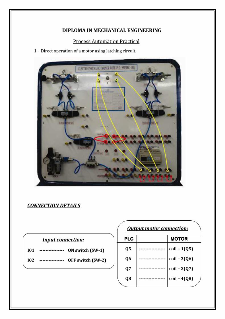
DIPLOMA IN MECHANICAL ENGINEERING
Process Automation Practical
1. Direct operation of a motor using latching circuit.
CONNECTION DETAILS
Output motor connection:
PLCPLCPLCPLC MOTORMOTORMOTORMOTOR
Q5 ----------------- coil – 1(Q5)
Q6 ----------------- coil – 2(Q6)
Q7 ----------------- coil – 3(Q7)
Q8 ----------------- coil – 4(Q8)
Input connection:
I01 ---------------- ON switch (SW-1)
I02 ---------------- OFF switch (SW-2)
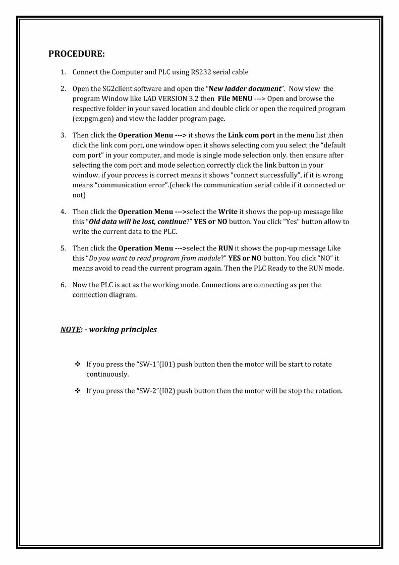
PROCEDURE:
1. Connect the Computer and PLC using RS232 serial cable
2. Open the SG2client software and open the “New ladder document”. Now view the
program Window like LAD VERSION 3.2 then File MENU ---> Open and browse the
respective folder in your saved location and double click or open the required program
(ex:pgm.gen) and view the ladder program page.
3. Then click the Operation Menu ---> it shows the Link com port in the menu list ,then
click the link com port, one window open it shows selecting com you select the “default
com port” in your computer, and mode is single mode selection only. then ensure after
selecting the com port and mode selection correctly click the link button in your
window. if your process is correct means it shows “connect successfully”, if it is wrong
means “communication error”.(check the communication serial cable if it connected or
not)
4. Then click the Operation Menu --->select the Write it shows the pop-up message like
this “Old data will be lost, continue?” YES or NO button. You click “Yes” button allow to
write the current data to the PLC.
5. Then click the Operation Menu --->select the RUN it shows the pop-up message Like
this “Do you want to read program from module?” YES or NO button. You click “NO” it
means avoid to read the current program again. Then the PLC Ready to the RUN mode.
6. Now the PLC is act as the working mode. Connections are connecting as per the
connection diagram.
NOTE: - working principles
� If you press the “SW-1”(I01) push button then the motor will be start to rotate
continuously.
� If you press the “SW-2”(I02) push button then the motor will be stop the rotation.
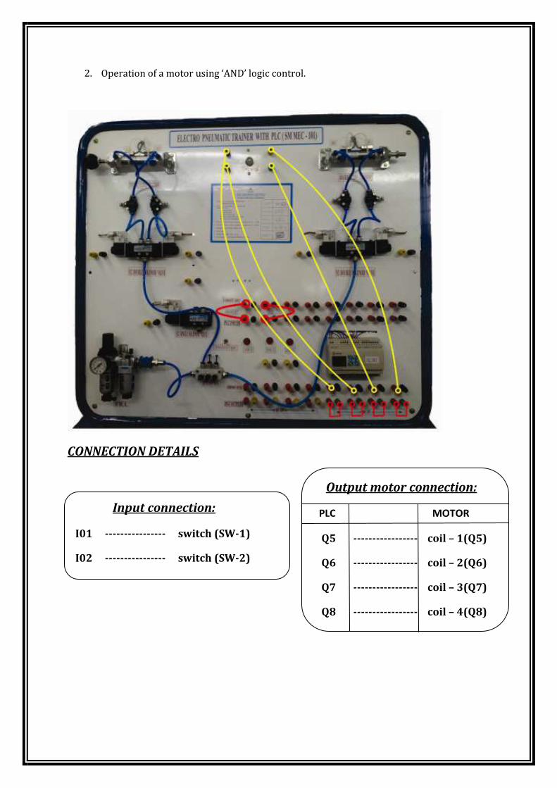
2. Operation of a motor using ‘AND’ logic control.
CONNECTION DETAILS
Input connection:
I01 ---------------- switch (SW-1)
I02 ---------------- switch (SW-2)
Output motor connection:
PLC MOTOR
Q5 ----------------- coil – 1(Q5)
Q6 ----------------- coil – 2(Q6)
Q7 ----------------- coil – 3(Q7)
Q8 ----------------- coil – 4(Q8)
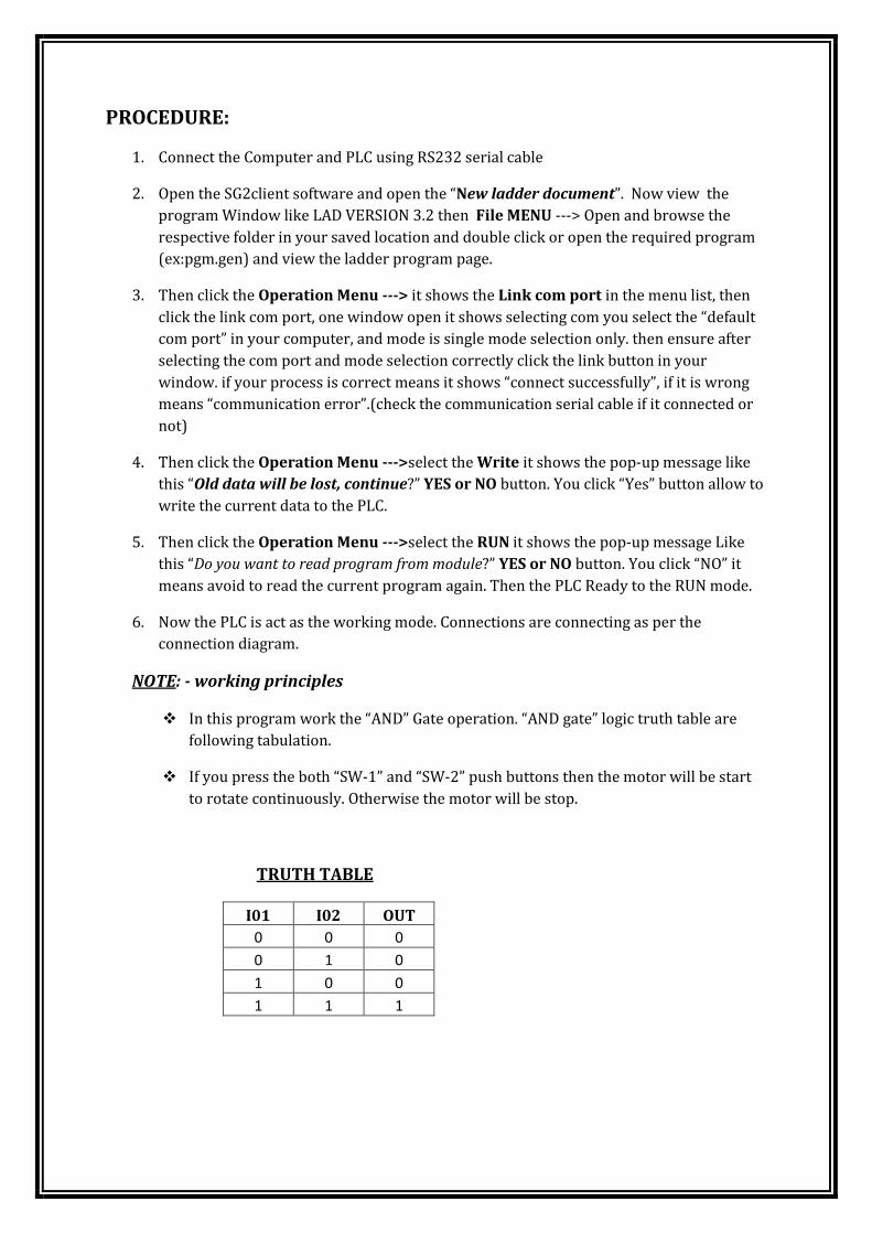
PROCEDURE:
1. Connect the Computer and PLC using RS232 serial cable
2. Open the SG2client software and open the “New ladder document”. Now view the
program Window like LAD VERSION 3.2 then File MENU ---> Open and browse the
respective folder in your saved location and double click or open the required program
(ex:pgm.gen) and view the ladder program page.
3. Then click the Operation Menu ---> it shows the Link com port in the menu list, then
click the link com port, one window open it shows selecting com you select the “default
com port” in your computer, and mode is single mode selection only. then ensure after
selecting the com port and mode selection correctly click the link button in your
window. if your process is correct means it shows “connect successfully”, if it is wrong
means “communication error”.(check the communication serial cable if it connected or
not)
4. Then click the Operation Menu --->select the Write it shows the pop-up message like
this “Old data will be lost, continue?” YES or NO button. You click “Yes” button allow to
write the current data to the PLC.
5. Then click the Operation Menu --->select the RUN it shows the pop-up message Like
this “Do you want to read program from module?” YES or NO button. You click “NO” it
means avoid to read the current program again. Then the PLC Ready to the RUN mode.
6. Now the PLC is act as the working mode. Connections are connecting as per the
connection diagram.
NOTE: - working principles
� In this program work the “AND” Gate operation. “AND gate” logic truth table are
following tabulation.
� If you press the both “SW-1” and “SW-2” push buttons then the motor will be start
to rotate continuously. Otherwise the motor will be stop.
TRUTH TABLE
I01 I02 OUT
0 0 0
0 1 0
1 0 0
1 1 1
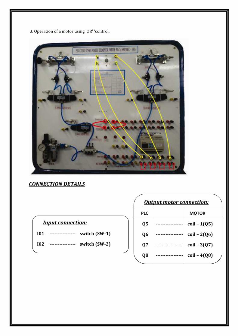
3. Operation of a motor using ‘OR’ ‘control.
CONNECTION DETAILS
Input connection:
I01 ---------------- switch (SW-1)
I02 ---------------- switch (SW-2)
Output motor connection:
PLC MOTOR
Q5 ----------------- coil – 1(Q5)
Q6 ----------------- coil – 2(Q6)
Q7 ----------------- coil – 3(Q7)
Q8 ----------------- coil – 4(Q8)
PROCEDURE:
1. Connect the Computer and PLC using RS232 serial cable
2. Open the SG2client software and open the “New ladder document”. Now view the
program Window like LAD VERSION 3.2 then File MENU ---> Open and browse the
respective folder in your saved location and double click or open the required program
(ex:pgm.gen) and view the ladder program page.
3. Then click the Operation Menu ---> it shows the Link com port in the menu list, then
click the link com port, one window open it shows selecting com you select the “default
com port” in your computer, and mode is single mode selection only. then ensure after
selecting the com port and mode selection correctly click the link button in your
window. if your process is correct means it shows “connect successfully”, if it is wrong
means “communication error”.(check the communication serial cable if it connected or
not)
4. Then click the Operation Menu --->select the Write it shows the pop-up message like
this “Old data will be lost, continue?” YES or NO button. You click “Yes” button allow to
write the current data to the PLC.
5. Then click the Operation Menu --->select the RUN it shows the pop-up message Like
this “Do you want to read program from module?” YES or NO button. You click “NO” it
means avoid to read the current program again. Then the PLC Ready to the RUN mode.
6. Now the PLC is act as the working mode. Connections are connecting as per the
connection diagram.
NOTE: - working principles
OR GATE - TRUTH TABLE
I01 I02 OUT
0 0 0
0 1 1
1 0 1
1 1 1
� In this program work the “OR” Gate operation. “OR” gate logic truth table is
attaching the above tabulation.
� If you press the “SW-1” or “SW-2” push buttons then the motor will be start.
� Similarly if you press the both “SW-1” and “SW-2” push buttons also the
motor will be start to rotate continuously.
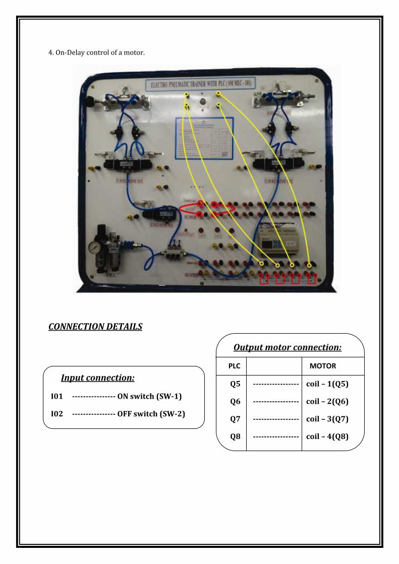
4. On-Delay control of a motor.
CONNECTION DETAILS
Input connection:
I01 ---------------- ON switch (SW-1)
I02 ---------------- OFF switch (SW-2)
Output motor connection:
PLC MOTOR
Q5 ----------------- coil – 1(Q5)
Q6 ----------------- coil – 2(Q6)
Q7 ----------------- coil – 3(Q7)
Q8 ----------------- coil – 4(Q8)
PROCEDURE:
1. Connect the Computer and PLC using RS232 serial cable
2. Open the SG2client software and open the “New ladder document”. Now view the
program Window like LAD VERSION 3.2 then File MENU ---> Open and browse the
respective folder in your saved location and double click or open the required program
(ex:pgm.gen) and view the ladder program page.
3. Then click the Operation Menu ---> it shows the Link com port in the menu list ,then
click the link com port, one window open it shows selecting com you select the “default
com port” in your computer, and mode is single mode selection only. then ensure after
selecting the com port and mode selection correctly click the link button in your
window. if your process is correct means it shows “connect successfully”, if it is wrong
means “communication error”.(check the communication serial cable if it connected or
not)
4. Then click the Operation Menu --->select the Write it shows the pop-up message like
this “Old data will be lost, continue?” YES or NO button. You click “Yes” button allow to
write the current data to the PLC.
5. Then click the Operation Menu --->select the RUN it shows the pop-up message Like
this “Do you want to read program from module?” YES or NO button. You click “NO” it
means avoid to read the current program again. Then the PLC Ready to the RUN mode.
6. Now the PLC is act as the working mode. Connections are connecting as per the
connection diagram.
NOTE: - working principles
� In this program work the “ON” time delay of the motor.
� If you press the switch“SW-1 ON” condition the delay time is running at a
particular user defined time (the user can set the delay time or can vary
the delay time accordingly using the program). Once the delay time is
over, then the motor gets ON continuously.
� If you press the switch “SW-2” then the motor will be stop the rotation.
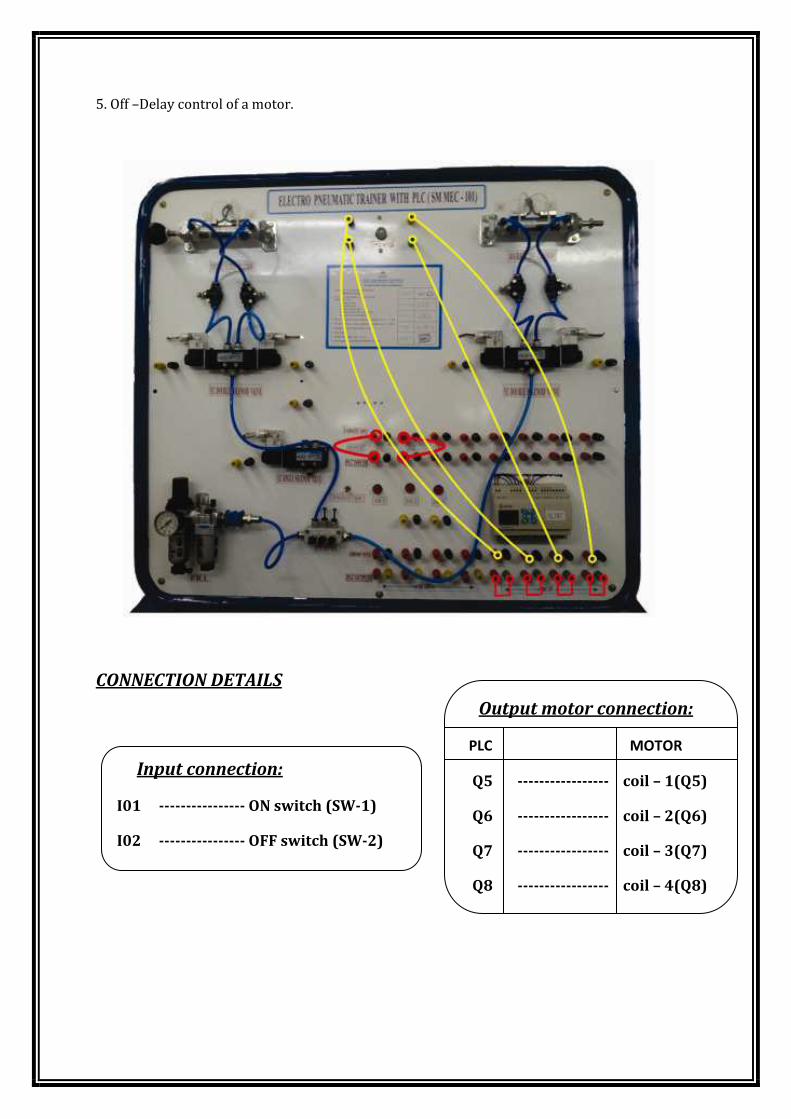
5. Off –Delay control of a motor.
CONNECTION DETAILS
Input connection:
I01 ---------------- ON switch (SW-1)
I02 ---------------- OFF switch (SW-2)
Output motor connection:
PLC MOTOR
Q5 ----------------- coil – 1(Q5)
Q6 ----------------- coil – 2(Q6)
Q7 ----------------- coil – 3(Q7)
Q8 ----------------- coil – 4(Q8)
PROCEDURE:
1. Connect the Computer and PLC using RS232 serial cable
2. Open the SG2client software and open the “New ladder document”. Now view the
program Window like LAD VERSION 3.2 then File MENU ---> Open and browse the
respective folder in your saved location and double click or open the required program
(ex:pgm.gen) and view the ladder program page.
3. Then click the Operation Menu ---> it shows the Link com port in the menu list ,then
click the link com port, one window open it shows selecting com you select the “default
com port” in your computer, and mode is single mode selection only. then ensure after
selecting the com port and mode selection correctly click the link button in your
window. if your process is correct means it shows “connect successfully”, if it is wrong
means “communication error”.(check the communication serial cable if it connected or
not)
4. Then click the Operation Menu --->select the Write it shows the pop-up message like
this “Old data will be lost, continue?” YES or NO button. You click “Yes” button allow to
write the current data to the PLC.
5. Then click the Operation Menu --->select the RUN it shows the pop-up message Like
this “Do you want to read program from module?” YES or NO button. You click “NO” it
means avoid to read the current program again. Then the PLC Ready to the RUN mode.
6. Now the PLC is act as the working mode. Connections are connecting as per the
connection diagram.
NOTE: - working principles
� In this program work the “OFF” time delay of the motor.
� If you press the switch “SW-1” then the motor will be start to rotate.
� If you press the switch“SW-2 ON” condition the off delay time is running
at a particular user defined time (the user can set the delay time or can
vary the delay time accordingly using the program). Once the delay time
is over, then the motor gets OFF continuously.

6. Automatic operation of a Double acting cylinder-single cycle.
CONNECTION DETAILS
Input connection:
I01 ---------------- ON switch (SW-1)
I05 ---------------- Read switch
Output motor connection:
PLC D.S.VALVE
Q1 ----------------- coil – 1(S1)
Q2 ----------------- coil – 2(S2)

PROCEDURE:
1. Connect the Computer and PLC using RS232 serial cable
2. Open the SG2client software and open the “New ladder document”. Now view the
program Window like LAD VERSION 3.2 then File MENU ---> Open and browse the
respective folder in your saved location and double click or open the required program
(ex:pgm.gen) and view the ladder program page.
3. Then click the Operation Menu ---> it shows the Link com port in the menu list ,then
click the link com port, one window open it shows selecting com you select the “default
com port” in your computer, and mode is single mode selection only. then ensure after
selecting the com port and mode selection correctly click the link button in your
window. if your process is correct means it shows “connect successfully”, if it is wrong
means “communication error”.(check the communication serial cable if it connected or
not)
4. Then click the Operation Menu --->select the Write it shows the pop-up message like
this “Old data will be lost, continue?” YES or NO button. You click “Yes” button allow to
write the current data to the PLC.
5. Then click the Operation Menu --->select the RUN it shows the pop-up message Like
this “Do you want to read program from module?” YES or NO button. You click “NO” it
means avoid to read the current program again. Then the PLC Ready to the RUN mode.
6. Now the PLC is act as the working mode. Connections are connecting as per the
connection diagram.
NOTE: - working principles
� In this exercises double acting cylinder is act as the single acting cylinder using
PLC programming.
� Connect the switch “sw-1” (I01) connector using cable and, Reed switch“I05”
connector also connect. Then the output side Q1 is connect the S1 relay of the
solenoid valve, Q2 is connect the S2 relay of the solenoid valve.
� Initially switch ON the ‘sw-1’ now Q1 output is enable S1 relay ON so the
cylinder is move to forward direction.
� Suddenly Reed switch ‘I05’ is sense and ON the PLC input signal. So the PLC
output Q2 is enable so cylinder is automatically return.
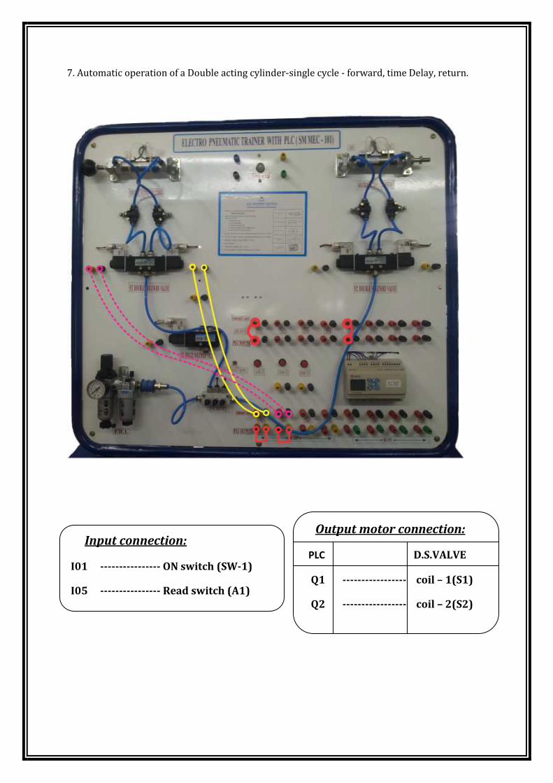
7. Automatic operation of a Double acting cylinder-single cycle - forward, time Delay, return.
Input connection:
I01 ---------------- ON switch (SW-1)
I05 ---------------- Read switch (A1)
Output motor connection:
PLC D.S.VALVE
Q1 ----------------- coil – 1(S1)
Q2 ----------------- coil – 2(S2)
PROCEDURE:
1. Connect the Computer and PLC using RS232 serial cable
2. Open the SG2client software and open the “New ladder document”. Now view the
program Window like LAD VERSION 3.2 then File MENU ---> Open and browse the
respective folder in your saved location and double click or open the required program
(ex:pgm.gen) and view the ladder program page.
3. Then click the Operation Menu ---> it shows the Link com port in the menu list ,then
click the link com port, one window open it shows selecting com you select the “default
com port” in your computer, and mode is single mode selection only. then ensure after
selecting the com port and mode selection correctly click the link button in your
window. if your process is correct means it shows “connect successfully”, if it is wrong
means “communication error”.(check the communication serial cable if it connected or
not)
4. Then click the Operation Menu --->select the Write it shows the pop-up message like
this “Old data will be lost, continue?” YES or NO button. You click “Yes” button allow to
write the current data to the PLC.
5. Then click the Operation Menu --->select the RUN it shows the pop-up message Like
this “Do you want to read program from module?” YES or NO button. You click “NO” it
means avoid to read the current program again. Then the PLC Ready to the RUN mode.
6. Now the PLC is act as the working mode. Connections are connecting as per the
connection diagram.
NOTE: - working principles
� In this exercises double acting cylinder is act as the single cycle - forward, time
Delay, return.
� Connect the switch “sw-1” (I01) connector using cable and, Reed switch“I05”
connector also connect. Then the output side Q1 is connect the S1 relay of the
solenoid valve, Q2 is connect the S2 relay of the solenoid valve.
� Initially switch ON the ‘sw-1’ now Q1 output is enable S1 relay ON so the
cylinder is move to forward direction.
� Suddenly Reed switch ‘I05’ is sense and ON the PLC input signal. So the delay
time is running at a particular user defined time. When the delay time is
end PLC output Q2 is enable cylinder is automatically return.
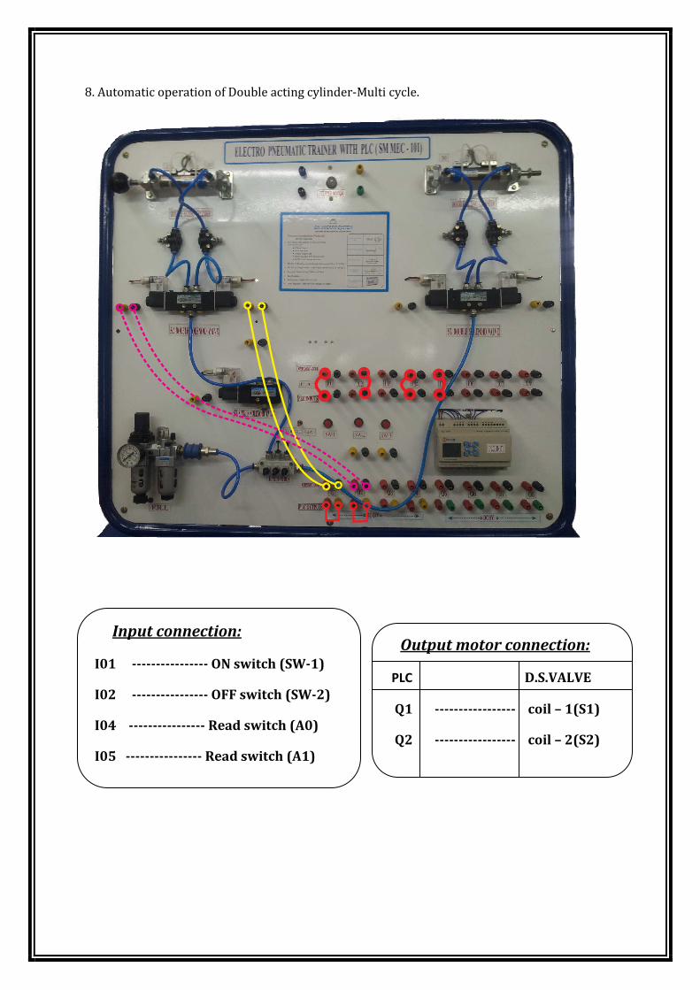
8. Automatic operation of Double acting cylinder-Multi cycle.
Input connection:
I01 ---------------- ON switch (SW-1)
I02 ---------------- OFF switch (SW-2)
I04 ---------------- Read switch (A0)
I05 ---------------- Read switch (A1)
Output motor connection:
PLC D.S.VALVE
Q1 ----------------- coil – 1(S1)
Q2 ----------------- coil – 2(S2)
PROCEDURE:
1. Connect the Computer and PLC using RS232 serial cable
2. Open the SG2client software and open the “New ladder document”. Now view the
program Window like LAD VERSION 3.2 then File MENU ---> Open and browse the
respective folder in your saved location and double click or open the required program
(ex:pgm.gen) and view the ladder program page.
3. Then click the Operation Menu ---> it shows the Link com port in the menu list ,then
click the link com port, one window open it shows selecting com you select the “default
com port” in your computer, and mode is single mode selection only. then ensure after
selecting the com port and mode selection correctly click the link button in your
window. if your process is correct means it shows “connect successfully”, if it is wrong
means “communication error”.(check the communication serial cable if it connected or
not)
4. Then click the Operation Menu --->select the Write it shows the pop-up message like
this “Old data will be lost, continue?” YES or NO button. You click “Yes” button allow to
write the current data to the PLC.
5. Then click the Operation Menu --->select the RUN it shows the pop-up message Like
this “Do you want to read program from module?” YES or NO button. You click “NO” it
means avoid to read the current program again. Then the PLC Ready to the RUN mode.
6. Now the PLC is act as the working mode. Connections are connecting as per the
connection diagram.
NOTE: - working principles
� In this exercises double acting cylinder is Automatic operation of -Multi cycle
� Connect the switch “sw-1” (I01), “sw-2” (I02), (I04), (I05) connector are
connect using cable. Then the output side Q1 is connect the S1 relay of the
solenoid valve, Q2 is connect the S2 relay of the solenoid valve.
� Switch ON the ‘sw-1’ switch now Q1 output is enable S1 relay ON so the
cylinder piston is move to outside. Then the Reed switch is sense and signal is
passed the PLC input terminal ‘I05’. So the PLC output Q2 enable, now cylinder
piston is move to return to initial position. Then the ‘I04’ reed switch is sense
the piston magnet so the reed switch is ON. When the ‘I04’ is ON automatically
PLC output Q1 also ON so the cylinder piston is move to outside. In this process
continuously running.
� If you press the ‘I02’ push button the PLC output signals are disable. And also
solenoid valve relay’s supply voltage also off. So the cylinder operations are off.
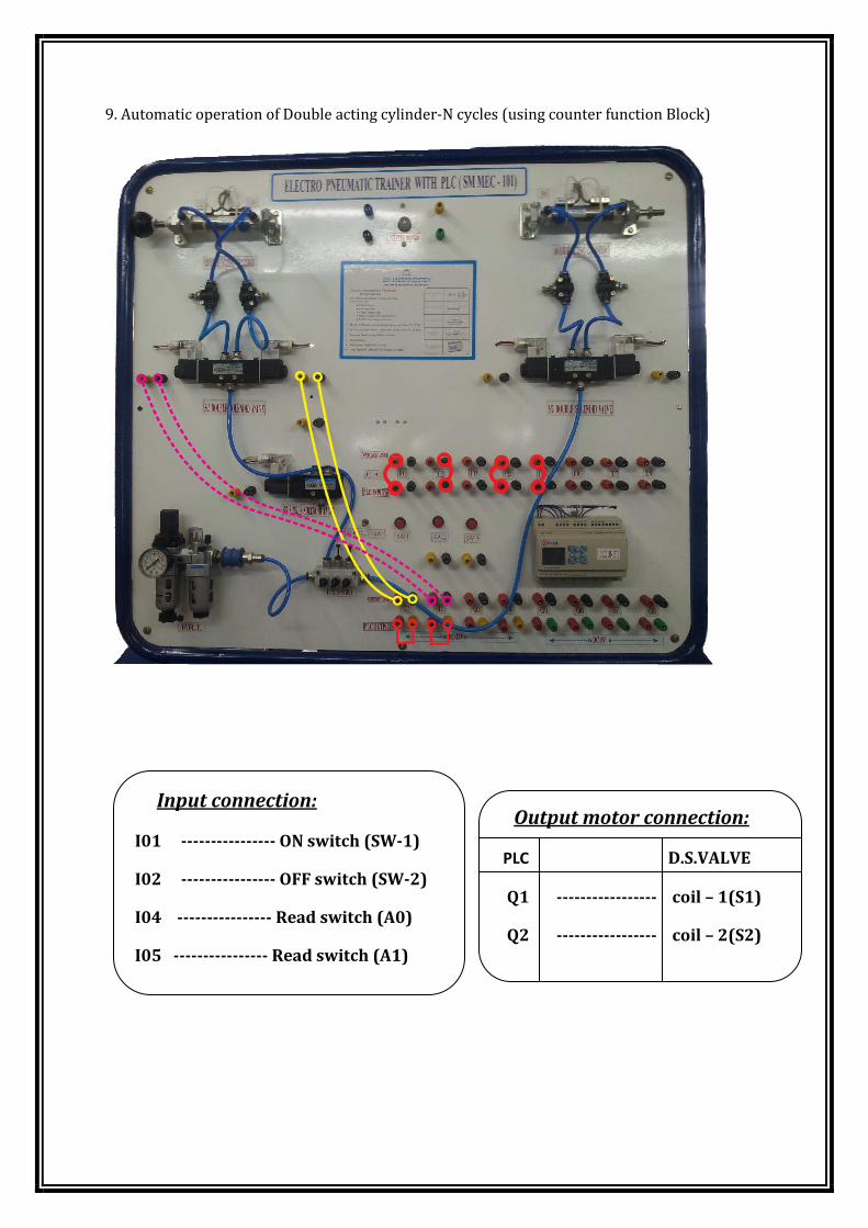
9. Automatic operation of Double acting cylinder-N cycles (using counter function Block)
Input connection:
I01 ---------------- ON switch (SW-1)
I02 ---------------- OFF switch (SW-2)
I04 ---------------- Read switch (A0)
I05 ---------------- Read switch (A1)
Output motor connection:
PLC D.S.VALVE
Q1 ----------------- coil – 1(S1)
Q2 ----------------- coil – 2(S2)
PROCEDURE:
1. Connect the Computer and PLC using RS232 serial cable
2. Open the SG2client software and open the “New ladder document”. Now view the
program Window like LAD VERSION 3.2 then File MENU ---> Open and browse the
respective folder in your saved location and double click or open the required program
(ex:pgm.gen) and view the ladder program page.
3. Then click the Operation Menu ---> it shows the Link com port in the menu list ,then
click the link com port, one window open it shows selecting com you select the “default
com port” in your computer, and mode is single mode selection only. then ensure after
selecting the com port and mode selection correctly click the link button in your
window. if your process is correct means it shows “connect successfully”, if it is wrong
means “communication error”.(check the communication serial cable if it connected or
not)
4. Then click the Operation Menu --->select the Write it shows the pop-up message like
this “Old data will be lost, continue?” YES or NO button. You click “Yes” button allow to
write the current data to the PLC.
5. Then click the Operation Menu --->select the RUN it shows the pop-up message Like
this “Do you want to read program from module?” YES or NO button. You click “NO” it
means avoid to read the current program again. Then the PLC Ready to the RUN mode.
6. Now the PLC is act as the working mode. Connections are connecting as per the
connection diagram.
NOTE: - working principles
� In this exercises double acting cylinder is Automatic operation of N cycles
(using counter function Block)
� Connect the switch “sw-1” (I01), “sw-2” (I02), (I04), (I05) connector are
connect using cable. Then the output side Q1 is connect the S1 relay of the
solenoid valve, Q2 is connect the S2 relay of the solenoid valve.
� In this program two counter functions are used, input counter and output
counter. (Example : input counter ‘ 2 ’, output counter ‘ 6 ’)
� If you press the push button ‘Sw-1’ switch now input counter is read the first
count, again press the switch counter is read the second count. So the Q1 output
is enable S1 relay ON so the cylinder piston is move to outside. Then the Reed
switch is sense and signal is passed the PLC input terminal ‘I05’. So the PLC
output Q2 enable, now cylinder piston is move to return to initial position.
Whenever the Q2 enables, output counter will be increased.
� PLC outputs will be stopped, while the counter reaches ‘6’.
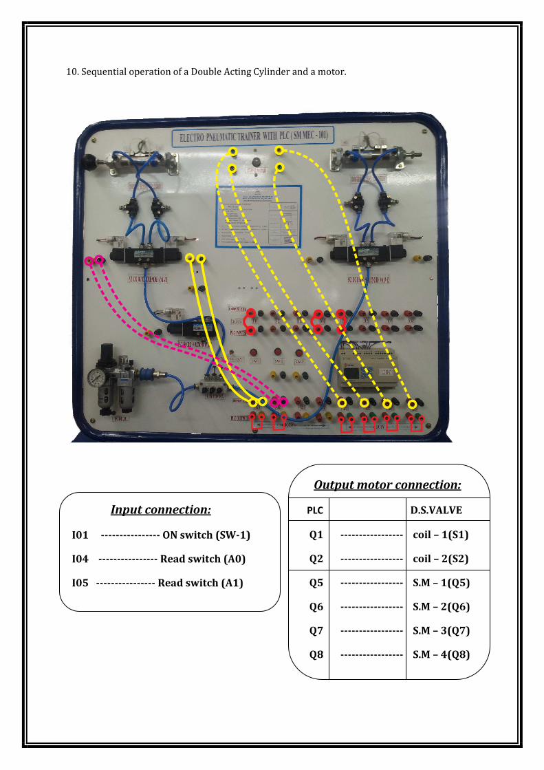
10. Sequential operation of a Double Acting Cylinder and a motor.
Input connection:
I01 ---------------- ON switch (SW-1)
I04 ---------------- Read switch (A0)
I05 ---------------- Read switch (A1)
Output motor connection:
PLC D.S.VALVE
Q1 ----------------- coil – 1(S1)
Q2 ----------------- coil – 2(S2)
Q5 ----------------- S.M – 1(Q5)
Q6 ----------------- S.M – 2(Q6)
Q7 ----------------- S.M – 3(Q7)
Q8 ----------------- S.M – 4(Q8)
PROCEDURE:
1. Connect the Computer and PLC using RS232 serial cable
2. Open the SG2client software and open the “New ladder document”. Now view the
program Window like LAD VERSION 3.2 then File MENU ---> Open and browse the
respective folder in your saved location and double click or open the required program
(ex:pgm.gen) and view the ladder program page.
3. Then click the Operation Menu ---> it shows the Link com port in the menu list ,then
click the link com port, one window open it shows selecting com you select the “default
com port” in your computer, and mode is single mode selection only. then ensure after
selecting the com port and mode selection correctly click the link button in your
window. if your process is correct means it shows “connect successfully”, if it is wrong
means “communication error”.(check the communication serial cable if it connected or
not)
4. Then click the Operation Menu --->select the Write it shows the pop-up message like
this “Old data will be lost, continue?” YES or NO button. You click “Yes” button allow to
write the current data to the PLC.
5. Then click the Operation Menu --->select the RUN it shows the pop-up message Like
this “Do you want to read program from module?” YES or NO button. You click “NO” it
means avoid to read the current program again. Then the PLC Ready to the RUN mode.
6. Now the PLC is act as the working mode. Connections are connecting as per the
connection diagram.
NOTE: - working principles
� In this exercises Sequential operation of a Double Acting Cylinder and a motor.
� Connect the switch “Sw-1” (I01), “Sw-2” (I02), (I04), (I05) connector are
connect using cable. Then the output Q1 is connect the S1 relay of the solenoid
valve, Q2 is connect the S2 relay of the solenoid valve. And also stepper motor
connections are connecting using the connection diagram.
� In this program work the sequential input and output operation of the motor
and cylinder.
� When will be press the “SW-1” push button Q1 is ON so the cylinder piston
move to outside, in this same time stepper motor will be start to run. When the
Q1 is enable time delay is ON.
� PLC output Q2 is ON Motor will be stopped and also cylinder piston, while the
delay time reaches.

11. Sequential operation of two Double Acting Cylinders for the sequence A+,B+, B-, A-.
Input connection:
I01 ---------------- ON switch (SW-1)
I03 ---------------- ON switch (SW-3)
I04 ---------------- Read switch (A0)
I05 ---------------- Read switch (A1)
I06 ---------------- Read switch (B0)
I07 ---------------- Read switch (B1)
Output motor connection:
PLC D.S.VALVE
Q1 ----------------- coil – 1(S1)
Q2 ----------------- coil – 2(S2)
Q3 ----------------- coil – 3(S3)
Q4 ----------------- coil – 4(S4)
PROCEDURE:
1. Connect the Computer and PLC using RS232 serial cable
2. Open the SG2client software and open the “New ladder document”. Now view the
program Window like LAD VERSION 3.2 then File MENU ---> Open and browse the
respective folder in your saved location and double click or open the required program
(ex:pgm.gen) and view the ladder program page.
3. Then click the Operation Menu ---> it shows the Link com port in the menu list ,then
click the link com port, one window open it shows selecting com you select the “default
com port” in your computer, and mode is single mode selection only. then ensure after
selecting the com port and mode selection correctly click the link button in your
window. if your process is correct means it shows “connect successfully”, if it is wrong
means “communication error”.(check the communication serial cable if it connected or
not)
4. Then click the Operation Menu --->select the Write it shows the pop-up message like
this “Old data will be lost, continue?” YES or NO button. You click “Yes” button allow to
write the current data to the PLC.
5. Then click the Operation Menu --->select the RUN it shows the pop-up message Like
this “Do you want to read program from module?” YES or NO button. You click “NO” it
means avoid to read the current program again. Then the PLC Ready to the RUN mode.
6. Now the PLC is act as the working mode. Connections are connecting as per the
connection diagram.
NOTE: - working principles
� In this exercises Sequential operation of two Double Acting Cylinders for the
sequence A+,B+, B-, A-.
� Connect the switch “sw-1” (I01), “sw-3” (I03), (I04), (I05), (I06), (I07),
connector is connecting using cable. Then the output side Q1 is connect the S1
relay of the solenoid valve, Q2 is connect the S2 relay of the solenoid valve. Q3 is
connecting S3 solenoid valve and also Q4 is connect the S4 solenoid valve.
� If you press the push button ‘Sw-1’ the sequential operation will start from Q3
then the cylinder A+ will go outside., after this Q1 will be enabled then B+ will
go outside then Q2 will enable the B- to move inside and the Q4 will make A- go
inside.
� After this full sequence the operation can be stopped by pressing the ‘SW-2’
push switch.