process and requirements for imtprocess and requirements ... · process and requirements for...
TRANSCRIPT

WINNER+
Process and Requirements for IMT-AdvancedProcess and Requirements for IMT-AdvancedProcess and Requirements for IMT AdvancedProcess and Requirements for IMT Advanced
Miia MustonenVTT Technical Research Centre of Finland
Slide 1Event: CWC & VTT GIGA Seminar 2008Date: 4th of December 2008

WINNER+ OutlineOutline• Definitions• Process and time schedule of IMT Advanced• Process and time schedule of IMT-Advanced• Minimum requirements
Technical Performance– Technical Performance– Spectrum– Services
• Evaluation guidelines• Evaluation methodsEvaluation methods• Candidate RITs
Slide 2Event: CWC & VTT GIGA Seminar 2008Date: 4th of December 2008

WINNER+ DefinitionsDefinitions• International Telecommunication
Union (ITU) is an international Mobility
organization within United Nations where governments and the private
t di t l b lIMT-2000
NewMobileAccessEnhanced
IMT-2000
High
IMT
sector coordinate global telecommunication networks andservices It is the only body which New Nomadic / Local
IMT-2000
EnhancementMedium IMT-ADVANCED
IMT 2000services. It is the only body whichis responsible for recommending standards for International Mobile
1 10 100 1000
New Nomadic / LocalArea Wireless AccessLow
Communication speed / Carrier bitrate (Mbit/s)
IMT-2000
Telecommunication (IMT) systems.• ITU-R WP 5D is responsible for IMT Systems
IMT 2000 ll 3G bil i ti t d d• IMT-2000 encompasses all 3G mobile communication standards and their enhancements
Slide 3Event: CWC & VTT GIGA Seminar 2008Date: 4th of December 2008

WINNER+ Definitions Definitions • IMT-Advanced is the ITU name for systems beyond IMT-2000 i.e., 4G
systems A bil t th t i l d th biliti f IMT• A mobile system that includes the new capabilities of IMT
• Provides access to a wide range of telecommunication services supported by mobile and fixed networks
• Supports low to high mobility applications and a wide range of data rates according to user and service demands in multiple environments.
• Key Features of IMT-Advanced [M.1822]y [ ]– A high degree of commonality of functionality worldwide while flexibility to
support a wide range of services and applications cost efficiently. – Compatibility of services within IMT and with fixed networks. – Capability of interworking with other radio access systems. – High quality mobile services.– User equipment suitable for worldwide use.– User-friendly applications, services and equipment. – Worldwide roaming capability. – Enhanced peak data rates to support advanced services and applications.
Slide 4Event: CWC & VTT GIGA Seminar 2008Date: 4th of December 2008
p pp pp

WINNER+ Definition of Candidate RIT/SRITDefinition of Candidate RIT/SRIT• A Radio Interface Technology (RIT) can enter the process
to become an IMT-Advanced technology if it fulfils the minimum requirements for at least one test environment (indoor, microcellular, base coverage urban and high speed)speed).
• However, an RIT cannot be accepted as an IMT-Advanced technology unless it fulfils the minimum requirements in at gy qleast three of the test environments.
If an RIT enters the process not fulfilling the requirements in three of the test environments it can form a set of RITs (SRITs) with other RITs each individually fulfilling the(SRITs) with other RITs each individually fulfilling the minimum requirements for at least one test environment and complementing each other.
Slide 5Event: CWC & VTT GIGA Seminar 2008Date: 4th of December 2008

WINNER+ Definition of Circular LetterDefinition of Circular Letter
• The purpose of the Circular Letter (CL) for IMT-Advanced isIMT-Advanced is • to invite the ITU-R members and other
organizations to submit proposals for candidateorganizations to submit proposals for candidate Radio Interface Technologies or a set of RITs for terrestrial component of IMT-Advanced,
• to initiate the ongoing process to evaluate candidate RITs or SRITs for IMT-Advanced,
• to invite the formation of independent evaluation groups and subsequent submission of evaluation
treports
Slide 6Event: CWC & VTT GIGA Seminar 2008Date: 4th of December 2008

WINNER+Process and time schedule
of IMT-AdvancedProcess and time schedule
of IMT-Advanced
Slide 7Event: CWC & VTT GIGA Seminar 2008Date: 4th of December 2008

WINNER+ Minimum requirementsCell spectral efficiency
Minimum requirementsCell spectral efficiencyCell spectral efficiency Cell spectral efficiency
• Cell spectral efficiency (η) is defined as the aggregate throughput of all users (the number of correctly received bits by user i(d li k) f i ( li k) d li d t L 3(downlink) or from user i (uplink) χi delivered to Layer 3, over a certain period of time T) divided by the channel bandwidth ω and the number of cells M. Thus, N
∑MT
ii
⋅⋅=∑=
ω
χη 1
Test environment Downlink(bit/s/Hz/cell)
Uplink(bit/s/Hz/cell)
Indoor 3 2.25Microcellular 2.6 1.8B b 2 2 1 4Base coverage urban 2.2 1.4High speed 1.1 0.7
These values have been defined assuming an antenna configuration of downlink 4x2, uplink 2x4
Slide 8Event: CWC & VTT GIGA Seminar 2008Date: 4th of December 2008
These values have been defined assuming an antenna configuration of downlink 4x2, uplink 2x4

WINNER+ Minimum requirementsPeak Spectral Efficiency
Minimum requirementsPeak Spectral Efficiencyp yp y
• The peak spectral efficiency is the highest theoretical data rate (normalized by bandwidth), assuming error-free conditions assignable to a single mobile station, when all available radio resources for the corresponding link direction are utilized The minimum requirements for peakdirection are utilized. The minimum requirements for peak spectral efficiencies are
15 bit/s/Hz for downlink and– 15 bit/s/Hz for downlink and – 6.75 bit/s/Hz for uplink*.
E l D li k k d t t i 40 MH i 600 Mbit/• Examples: Downlink peak data rate in 40 MHz is 600 Mbit/s and in 100 MHz is 1 500 Mbit/s. Uplink peak data rate in 40 MHz is 270 Mbit/s and in 100 MHz is 675 Mbit/s.MHz is 270 Mbit/s and in 100 MHz is 675 Mbit/s.
Slide 9Event: CWC & VTT GIGA Seminar 2008Date: 4th of December 2008
*These values have been defined assuming an antenna configuration of downlink 4x4, uplink 2x4

WINNER+ Minimum requirements Cell edge user spectral efficiency
Minimum requirements Cell edge user spectral efficiencyCell edge user spectral efficiencyCell edge user spectral efficiency
• The cell edge user spectral efficiency is defined as 5% point of the cumulative distribution function (CDF) of the normalized user throughput. The normalized user throughput of user i, γi, is defined as
χγ = i
where χi denotes the number of correctly received bits of user i, Ti the active session time for user i and ω the
ωγ
⋅=
ii T
user i, Ti the active session time for user i and ω the channel bandwidth.
Test environment Downlink (bit/s/Hz)
Uplink (bit/s/Hz)(bit/s/Hz)
Indoor 0.1 0.07Microcellular 0 075 0 05Microcellular 0.075 0.05Base coverage urban 0.06 0.03High speed 0.04 0.015
Slide 10Event: CWC & VTT GIGA Seminar 2008Date: 4th of December 2008
g pThese values have been defined assuming an antenna configuration of downlink 4x2, uplink 2x4

WINNER+ Minimum requirementsLatency
Minimum requirementsLatencyLatencyLatency
Control plane (C-Plane) latency• Typically measured as the transition time from different yp y
connection modes. IMT-Advanced systems shall be able to achieve a transition time of less than 100 ms from idle state to an active state in such a way that the user plane isto an active state in such a way that the user plane is established.
User Plane Latency (transport delay)User Plane Latency (transport delay)• Defined as the one-way transit time between a packet
being available at the IP layer in the user terminal/base station and the availability of this packet at IP layer in the base station/user terminal. IMT-Advanced systems shall be able to achieve a user plane latency of less than 10 ms inable to achieve a user plane latency of less than 10 ms in unloaded conditions for small IP packets for both downlink and uplink.
Slide 11Event: CWC & VTT GIGA Seminar 2008Date: 4th of December 2008

WINNER+ Minimum requirements Mobility
Minimum requirements MobilityMobilityMobility
• The following mobility classes are defined: stationary (0 km/h), pedestrian(0 km/h-10 km/h), vehicular(10-120 km/h) and high
d hi l (120 350 k /h)speed vehicular (120-350 km/h)• The mobility classes to be supported by IMT-Advanced system
are listed in the table together with the traffic channel link data grate (normalized by bandwidth) that needs to be supported on the uplink when the user is moving at the maximum speed in that environmentenvironment.
Indoor Microcellular Base coverage urban
High speed
Mobility classes supported
Stationary, pedestrian
Stationary, pedestrian,Vehicular
(up to 30 km/h)
Stationary, pedestrian, vehicular
High speed vehicular, vehicular
Traffic channel link data rates* [bits/s/Hz]
1.0 0.75 0.55 0.25
Slide 12Event: CWC & VTT GIGA Seminar 2008Date: 4th of December 2008
*These values have been defined assuming an antenna configuration of downlink 4x2, uplink 2x4

WINNER+ Minimum requirements Handover
Minimum requirements HandoverHandoverHandover
• The handover interruption time is defined as the time duration during which a user terminal cannot exchange user plane packets with any base station. The IMT-Advanced system needs to support following handover interruption timesinterruption times
Handover type Interruption time (ms)Intra frequency 27 5Intra-frequency 27.5Inter-frequency– within a spectrum band 40
• In addition, inter-system handovers between the candidate
p– between spectrum bands 60
IMT-Advanced system and at least one IMT system shall be supported, but are not subject to handover interruption time limits
Slide 13Event: CWC & VTT GIGA Seminar 2008Date: 4th of December 2008
time limits.

WINNER+ Minimum requirementsVoIP Capacity
Minimum requirementsVoIP CapacityVoIP CapacityVoIP Capacity
• The VoIP capacity is the minimum of the calculated capacity for either link direction divided by the effective bandwidth (operating bandwidth normalized appropriately considering the uplink/downlink ratio) in the respective link directiondirection.
Test environment Min VoIP capacity (Active users/sector/MHz)( )
Indoor 50Microcellular 40Base coverage urban 40High speed 30
The values have been defined assuming an antenna configuration of 4x2 in the downlink and 2x4 in the uplink and a 12.2 kbit/s codec with a 50% activity factor such that the percentage of users in outage is less than 2%. A voice outage is experienced if less than 98% of the VoIP packets have been delivered successfully to the user within a one way radio access delay
Slide 14Event: CWC & VTT GIGA Seminar 2008Date: 4th of December 2008
packets have been delivered successfully to the user within a one way radio access delay bound of 50 ms.

WINNER+ Minimum requirementsBandwidth
Minimum requirementsBandwidthBandwidthBandwidth
• The RIT has to support a scalable bandwidth up to and including 40 MHz. This may be supported by g y pp ysingle or multiple RF carriers. Scalable bandwidth is the ability of the candidate RIT to operate with different b d id h ll ibandwidth allocations.
• It is required that the RIT supports at least threeb d idth lbandwidth values.
• Proponents are encouraged to consider extensions to support operation in wider bandwidths (e g up to 100support operation in wider bandwidths (e.g. up to 100 MHz) and the research targets expressed in Recommendation ITU-R M.1645
Slide 15Event: CWC & VTT GIGA Seminar 2008Date: 4th of December 2008
WINNER+ Minimum requirements Spectrum
Minimum requirements SpectrumSpectrumSpectrum
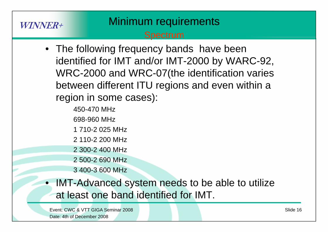
• The following frequency bands have been identified for IMT and/or IMT-2000 by WARC-92,identified for IMT and/or IMT 2000 by WARC 92, WRC-2000 and WRC-07(the identification varies between different ITU regions and even within a gregion in some cases):
450-470 MHz698-960 MHz1 710-2 025 MHz2 110-2 200 MHz2 300-2 400 MHz2 500-2 690 MHz3 400 3 600 MHz3 400-3 600 MHz
• IMT-Advanced system needs to be able to utilize at least one band identified for IMT
Slide 16Event: CWC & VTT GIGA Seminar 2008Date: 4th of December 2008
at least one band identified for IMT.

WINNER+ Minimum requirementsServices
Minimum requirementsServicesServicesServices
• An IMT-Advanced system has to support wide range of services. It has been defined that if the candidate RIT fulfills requirements on peak spectral efficiency, bandwidth and latency it also fulfills the requirement on wide range of services The support of the service classes is furtherservices. The support of the service classes is further analyzed by inspection in at least one test environment
User Experience Class Service ClassUser Experience Class Service ClassConversational Basic conversational service
Rich conversational serviceConversational low delayConversational low delay
Interactive Interactive high delayInteractive low delay
Streaming Streaming LiveStreaming Non-Live
Background Background
Slide 17Event: CWC & VTT GIGA Seminar 2008Date: 4th of December 2008
Background Background

WINNER+ Evaluation guidelinesEvaluation guidelines• Evaluation assessment methods
– Simulation (including system and link-level simulation)( g y )– Analytical (calculation based on technical information of the proposal)– Inspection (based on statements in the proposal)
• Options for evaluation groups– Self-evaluation
t b l t l ti• must be a complete evaluation– External evaluation group
• complete or partial evaluationcomplete or partial evaluation• one or several technology proposals• use their simulation tools for the evaluation
• WINNER+ has been accepted as an External Evaluation Group for the IMT-Advanced process in
Slide 18Event: CWC & VTT GIGA Seminar 2008Date: 4th of December 2008
ITU-R

WINNER+ Evaluation methodsEvaluation methodsMinimum Requirement Method for evaluation
Cell spectral efficiency Simulation (system level)p y ( y )
Peak spectral efficiency Analytical
Bandwidth Inspection
Cell edge user spectral efficiency Simulation (system level)
Control plane latency Analytical
U l l t A l ti lUser plane latency Analytical
Mobility Simulation (system and link level)
Intra- and inter-frequency handover interruption time Analyticalq y p y
Inter-system handover Inspection
VoIP Capacity Simulation (system level)
Deployment possible in at least one of the identified IMT bands Inspection
Channel bandwidth scalability Inspection
S t f id f i I ti
Slide 19Event: CWC & VTT GIGA Seminar 2008Date: 4th of December 2008
Support for a wide range of services Inspection

WINNER+ Candidate RITs Candidate RITs • 3GPP: An evolution of LTE (LTE Advanced)
• IEEE Project 802 16m: An evolution of the IEEE 802 16IEEE Project 802.16m: An evolution of the IEEE 802.16 WirelessMAN-OFDMA specification (OFDMA TDD WMAN developed by WiMAX Forum)
• 3GPP2: Not yet achieved consensus on which system the IMT-Advanced system will be based on (cdma2000, HRPD or UMB enhancement or new technology framework)enhancement or new technology framework)
• ARIB (Japan): Radio Interface Technology Group will develop one or more Japanese draft proposal(s) for IMT-Advanced whichone or more Japanese draft proposal(s) for IMT Advanced which will be submitted to ITU-R through Japan’s national process.
• TTA (Korea): will submit a proposal which will be based on ( ) p p3GPPs
For further information on these candidate RITs, see introduction of
Slide 20Event: CWC & VTT GIGA Seminar 2008Date: 4th of December 2008
the technologies from http://groups.itu.int/Default.aspx?tabid=383

WINNER+Related ITU-R Reports and RecommendationsRelated ITU-R Reports and RecommendationsITU-R Recommendation M.1645 (2003) "Framework and overall objectives
of the future development of IMT-2000 and systems beyond IMT-2000"ITU R Recommendation M 1768 (2006) "Methodology for calculation ofITU-R Recommendation M.1768 (2006) Methodology for calculation of
spectrum requirements for the future development of the terrestrial component of IMT-2000 and systems beyond IMT-2000"
ITU-R Recommendation M 1822 (2007) "Framework for services supportedITU-R Recommendation M.1822 (2007) Framework for services supported by IMT"
ITU-R Report M.2072 (2005) "World mobile telecommunication market forecast"forecast
ITU-R Report M.2074 (2005) "Radio aspects for the terrestrial component of IMT-2000 and systems beyond IMT-2000"
ITU-R Report M.2078 (2006) "Estimated spectrum bandwidth requirements p ( ) p qfor the future development of IMT-2000 and IMT-Advanced"
ITU-R Report M.2079 (2006) "Technical and operational information for identifying Spectrum for the terrestrial component of future development of IMT-2000 and IMT-Advanced"
Takagi H. and Walke B. H. (Eds.), Spectrum Requirement Planning in Wireless Communications: Model and Methodology for IMT-Advanced.
Slide 21Event: CWC & VTT GIGA Seminar 2008Date: 4th of December 2008
John Wiley & Sons, 2008. 248 p.

WINNER+
Thank you!Questions?Questions?
Miia Mustonen@vtt [email protected]
For further information visit a Web page for IMT-Advancedp ghttp://www.itu.int/ITU-R/go/rsg5-imt-advanced/
Slide 22Event: CWC & VTT GIGA Seminar 2008Date: 4th of December 2008