proceedings a new readout method for a high sensitivity
TRANSCRIPT

Eng. Proc. 2020, 1, Firstpage-Lastpage; doi: FOR PEER REVIEW www.mdpi.com/journal/engproc
Proceedings
A New Readout Method for a High Sensitivity
Capacitance Sensor Based on the Weakly Coupled
Resonators †
Vinayak Pachkawade
University of Liege, 4000 Liège, Belgium; [email protected] † Presented at the 7th Electronic Conference on Sensors and Applications, 15–30 November 2020; Available
online: https://ecsa-7.sciforum.net/.
Published: 15 November 2020
Abstract: This paper proposes a new readout method for a sensor to detect a minute variations into
the capacitance. A sensor is based on the weakly coupled electrical resonators that use an amplitude
ratio (AR) as an output signal. A new readout scheme with a relatively higher output sensitivity is
proposed to measure the relative changes into the input capacitor. A mathematical model is derived
to express the readout output as a function of change into the capacitance. To validate the theoretical
model, a system is modelled and designed using an industry-standard electronic circuit design
environment. A SPICE simulation results are presented for a wide range of design parameters, such
as varying coupling factors between the two electrical resonators. Sensitivity comparison between
the existing and the proposed AR readout is presented to show the effectiveness of the method of
detection proposed in this work.
Keywords: High-precision physical sensor; Coupled resonator sensor; Readout method for
capacitance sensor; WCR; Resonator; MEMS; Capacitance-to-Voltage converter; Readout for
Capacitive micromachined transducer
1. Introduction
In today’s world, an intelligent electronic circuits [1–3] to detect/ measure minute capacitance
change form an integral part of many micromachined/MEMS sensors [4–6]. Often the key design
requirements of such capacitive readouts are high sensitivity, ultra-high resolution (low noise floor),
low power consumption, etc. However, designing and implementing a high-performance capacitive
readout to precisely measure the minute variations in to the input capacitance pose various
challenges. These include intrinsic and extrinsic noise sources, board-level parasitics, etc. Recently, a
capacitance readout method based on the two weakly coupled resonators (WCR) has been used to
measure minute variations in a capacitance [2,7]. This research was done in the context of proposing
a readout method for capacitance sensors. Our work presents an innovative, and new readout
method to measure small capacitance changes into the micromachined/MEMS transducers. A
readout method reflects into the higher changes into the output voltage (relatively higher sensitivity)
for small incremental changes into the perturbation (capacitance). A readout circuit is called as
capacitance-to-amplitude/ amplitude ratio (AR) converter.
2. Mathematical Model
As shown in Figure 1, consider a RLC circuit that is used to form two electrically coupled
resonators (CR) to measure changes into the input capacitance. In this circuit, following assumptions
are valid: L1 = L2 = L, C1 = C2 = C and R1 = R2 = R. This establishes a symmetry in a circuit. A coupling
factor between the two individual RLC circuits is modelled as κ = C/Cc. A change into the input

Eng. Proc. 2020, 1, FOR PEER REVIEW 2
capacitance is ∆C. The normalized value of the capacitance change (in the form of a perturbation) is
expressed as δ = ∆C/C. Condition for a coupling is given as Cc >> C, indicating two resonant modes
can be reasonably distinguished into the output frequency response. The quantities V1(t) and V2(t)
are input voltages and quantities I1(t) and I1(t) are the output loop currents.
Figure 1. A circuit level schematic representation of a RLC readout.
Assuming no damping in the system, i.e., R = 0, a set of governing differential equations are
represented as
1 1 1 2 1
1 1(t) (t) (t) (t) (t)
c
Lq q q q VC C
(1)
2 2 2 1 2
1 1(t) (t) (t) (t) (t)
c
Lq q q q VC C C
(2)
It is assumed that system is driven with only one voltage source, i.e. V1 (s) ≠ 0, and V2 (s) = 0. Applying
Laplace Transform to Equations (1) and (2) yield the following:
21 2 1
1 1 1(s) (s) ( )
c c
Ls Q Q V sC C C
(3)
22 1
1 1 1(s) (s) 0
c c
Ls Q QC C C C
(4)
Solving further one can obtain the transfer functions as
2
11
2 4 21
1 1(j )
(j )2(j )
LQ C C CH
L L LVL
C Cc C C
(5)
22
2 4 21
1(j )
(j )2(j )
Q CcHL L LV
LC Cc C C
(6)
Here, =2
1 1 1
c c cc CC C C CCC CC
.
The denominator in (5) and (6) is the characteristic equation which provide the roots. In other
words, the roots or eigen-frequencies, 2i (i = 1, 2) as a function of ∆C are obtained as follows:
2
2
2
2
2 24
2
c c
i
L L L L L LL
C C C C C C C C
L
(7)

Eng. Proc. 2020, 1, FOR PEER REVIEW 3
Using (7) in (5) and (6), and taking the ratio of 1(j )H and 2 (j )H , i.e., 1
2
(j )
(j )i
i
Q
Q
provides the charge
output amplitude ratio (AR). The amplitude ratio, iAR (i = 1, 2) as a function of ∆C then is obtained as
2
2
21
2
2 24
1 1(j ) 2
1(j )
c c
i
i
L L L L L LL
C C C C C C C CL
Q L C C CQ
Cc
(8)
3. SPICE Modeling and Results
Figure 2a shows a resulting plots of the output loop currents of a RLC readout circuit model
seen in Figure 1. A fixed value of the coupling capacitor Cc is used for the simulation. Note that equal
output amplitudes of the loop currents represent initial symmetry of the system. Figure 2b presents
similar plots of the output loop currents for varying values of the coupling capacitor Cc. Higher
effective values of Cc leads to the lower effective value of a coupling between the two resonant
circuits. A relatively weaker coupling is reflected by the closed-spacing of the mode-frequencies as
seen from the plots.
(a)
(b)
Eng. Proc. 2020, 1, FOR PEER REVIEW 4
Figure 2. (a) Frequency response of a coupled RLC system for a fixed value of a coupling, magnitude
(left) and phase (right); (b) Frequency response of a coupled RLC system for variants of effective
coupling. Lower coupling leads to closely-spaced mode frequenices.
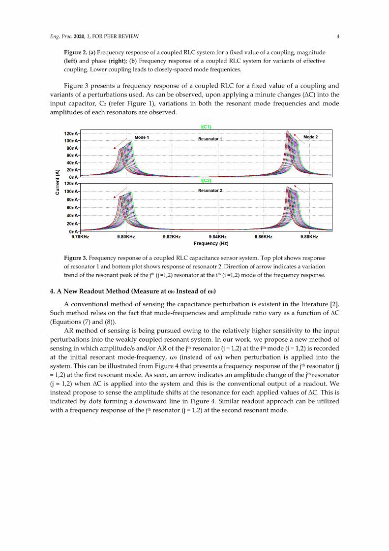
Figure 3 presents a frequency response of a coupled RLC for a fixed value of a coupling and
variants of a perturbations used. As can be observed, upon applying a minute changes (∆C) into the
input capacitor, C2 (refer Figure 1), variations in both the resonant mode frequencies and mode
amplitudes of each resonators are observed.
Figure 3. Frequency response of a coupled RLC capacitance sensor system. Top plot shows response
of resonator 1 and bottom plot shows response of resonaotr 2. Direction of arrow indicates a variation
trend of the resonant peak of the jth (j =1,2) resonator at the ith (i =1,2) mode of the frequency response.
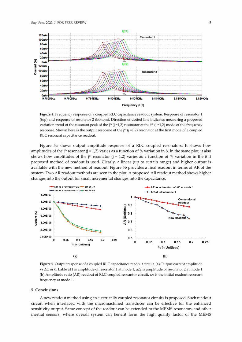
4. A New Readout Method (Measure at ω0 Instead of ωi)
A conventional method of sensing the capacitance perturbation is existent in the literature [2].
Such method relies on the fact that mode-frequencies and amplitude ratio vary as a function of ∆C
(Equations (7) and (8)).
AR method of sensing is being pursued owing to the relatively higher sensitivity to the input
perturbations into the weakly coupled resonant system. In our work, we propose a new method of
sensing in which amplitude/s and/or AR of the jth resonator (j = 1,2) at the ith mode (i = 1,2) is recorded
at the initial resonant mode-frequency, ω0 (instead of ωi) when perturbation is applied into the
system. This can be illustrated from Figure 4 that presents a frequency response of the jth resonator (j
= 1,2) at the first resonant mode. As seen, an arrow indicates an amplitude change of the jth resonator
(j = 1,2) when ∆C is applied into the system and this is the conventional output of a readout. We
instead propose to sense the amplitude shifts at the resonance for each applied values of ∆C. This is
indicated by dots forming a downward line in Figure 4. Similar readout approach can be utilized
with a frequency response of the jth resonator (j = 1,2) at the second resonant mode.
Eng. Proc. 2020, 1, FOR PEER REVIEW 5
Figure 4. Frequency response of a coupled RLC capacitance readout system. Response of resonator 1
(top) and response of resonator 2 (bottom). Direction of dotted line indicates measuring a proposed
variation trend of the resonant peak of the jth (j =1,2) resonator at the ith (i =1,2) mode of the frequency
response. Shown here is the output resposne of the jth (j =1,2) resonator at the first mode of a coupled
RLC resonant capacitance readout.
Figure 5a shows output amplitude response of a RLC coupled resonators. It shows how
amplitudes of the jth resonator (j = 1,2) varies as a function of % variation in δ. In the same plot, it also
shows how amplitudes of the jth resonator (j = 1,2) varies as a function of % variation in the δ if
proposed method of readout is used. Clearly, a linear (up to certain range) and higher output is
available with the new method of readout. Figure 5b provides a final readout in terms of AR of the
system. Two AR readout methods are seen in the plot. A proposed AR readout method shows higher
changes into the output for small incremental changes into the capacitance.
(a) (b)
Figure 5. Output response of a coupled RLC capacitance readout circuit. (a) Output current amplitude
vs ∆C or δ. Lable a11 is amplitude of resonator 1 at mode 1, a22 is amplitude of resonator 2 at mode 1
(b) Amplitude ratio (AR) readout of RLC coupled resoantor circuit. ω0 is the initial readout resonant
frequency at mode 1.
5. Conclusions
A new readout method using an electrically coupled resonator circuits is proposed. Such readout
circuit when interfaced with the micromachined transducer can be effective for the enhanced
sensitivity output. Same concept of the readout can be extended to the MEMS resonators and other
inertial sensors, where overall system can benefit form the high quality factor of the MEMS

Eng. Proc. 2020, 1, FOR PEER REVIEW 6
transducers/sensors. Extended work should involve improving the linearity in the output of the
proposed readout method.
Funding: This research received no external funding.
Conflicts of Interest: The authors declare no conflict of interest.
References
1. Pérez Sanjurjo, J.; Prefasi, E.; Buffa, C.; Gaggl, R. A Capacitance-To-Digital Converter for MEMS Sensors
for Smart Applications. Sensors 2017, 17, 1312.
2. Hafizi-Moori, S.; Cretu, E. Weakly-coupled resonators in capacitive readout circuits. IEEE Trans. Circ. Syst.
I Regul. Pap. 2015, 62, 337–346.
3. Qiao, Z.; Boom, B.A.; Annema, A.J.; Wiegerink, R.J.; Nauta, B. On frequency-based interface circuits for
capacitive MEMS accelerometers. Micromachines 2018, 9, 488.
4. Utz, A.; Walk, C.; Stanitzki, A.; Mokhtari, M.; Kraft, M.; Kokozinski, R. A High-Precision and High-
Bandwidth MEMS-Based Capacitive Accelerometer. IEEE Sens. J. 2018, 18, 6533–6539.
5. Kose, T.; Terzioglu, Y.; Azgin, K.; Akin, T. A single-mass self-resonating closed-loop capacitive MEMS
accelerometer. In Proceedings of the IEEE Sensors, Orlando, FL, USA, 30 October–3 November 2017.
6. Nazemi, H.; Balasingam, J.A.; Swaminathan, S.; Ambrose, K.; Nathani, M.U.; Ahmadi, T. Mass sensors
based on capacitive and piezoelectric micromachined ultrasonic transducers—CMUT and PMUT. Sensors
2020, 20, 2010.
7. Hafizi-Moori, S.; Cretu, E. Reducing measurement error in capacitive readout circuits based on weakly
coupled resonators. IEEE Sens. J. 2017, 17, 735–744.
Publisher's Note: MDPI stays neutral with regard to jurisdictional claims in published maps and institutional
affiliations.
© 2020 by the authors. Submitted for possible open access publication under the terms
and conditions of the Creative Commons Attribution (CC BY) license
(http://creativecommons.org/licenses/by/4.0/).