procedure transmission division - · pdf fileprocedure for self-build customer projects in...
TRANSCRIPT

CONTROLLED DISCLOSURE When downloaded from the EDS database, this document is uncontrolled and the responsibility rests with the user to ensure it
is in line with the authorized version on the database.
Procedure
Transmission
Division
Title: Procedure for Self-Build Customer Projects in Transmission
Unique Identifier: 240-61713594
Alternative Reference Number: N/A
Area of Applicability: Transmission
Documentation Type: Procedure
Revision: 0
Total Pages: 71
Next Review Date: September 2015
Disclosure Classification: CONTROLLED DISCLOSURE
Procedure for Self-Build Customer Projects in Transmission
CONTROLLED DISCLOSURE When downloaded from the EDS database, this document is uncontrolled and the responsibility rests with the user to ensure it
is in line with the authorized version on the database.
Unique Identifier: 240-61713594 Revision: 0 Page: 2 of 71
CONTENTS PAGE
1. INTRODUCTION ...................................................................................................................................................... 4
2. SUPPORTING CLAUSES ............................. ........................................................................................................... 4
2.1 SCOPE .............................................................................................................................................................. 4 2.1.1 Purpose ..................................................................................................................................................... 4 2.1.2 Applicability................................................................................................................................................ 4
2.2 NORMATIVE/INFORMATIVE REFERENCES .................................................................................................. 4 2.2.1 Normative .................................................................................................................................................. 4 2.2.2 Informative ................................................................................................................................................. 5
2.3 DEFINITIONS .................................................................................................................................................... 5 2.3.1 Classification ...............................................................................................................................................
2.4 ABBREVIATIONS .............................................................................................................................................. 8 2.5 ROLES AND RESPONSIBILITIES .................................................................................................................. 10 2.6 PROCESS FOR MONITORING ...................................................................................................................... 10 2.7 RELATED/SUPPORTING DOCUMENTS ...........................................................................................................
3. GENERAL CONDITIONS AND GUIDELINES FOR SELF-BUID PROJECTS ..................................................... 10
3.1 KEY PRINCIPLES AND CONDITIONS ........................................................................................................... 12 3.2 APPLICATION FOR SELF-BUILD .................................................................................................................. 12
3.3 THE SELF-BUILD PROCESS AND ITS LINKAGES WITH THE ESKOM QUOTATION AND EIA
PROCESSES.
3.4 ALLOCATION OF RESPONSIBILITIES BETWEEN ESKOM AND THE CUSTOMER IN A SELF-
BUILD PROJECT.
3.5 CONNECTION CHARGES APPLICABLE TO SELF BUILD PROJECTS
3.6 HOLDING POINTS TO ASSURE COMPLIANCE TO ESKOM STANDARDS AND
SPECIFICATIONS
4. AUTHORIZATION .................................. ................................................................................................................ 18
5. REVISIONS ............................................................................................................................................................ 19
6. DEVELOPMENT TEAM ............................... .......................................................................................................... 19
7. ACKNOWLEDGEMENTS ............................... ....................................................................................................... 20
APPENDIX A : ESKOM’S CONDITIONS AND REQUIREMENTS FO R SELF-BUILD PROJECTS ....................... 20
APPENDIX B : CHECKLIST OF ESKOM’S HOLDING POINTS .. .......................................................................... ..21
APPENDIX C : APPLICABLE STANDARDS, SPECIFICATIONS, GUIDELINES, ETC ......................................... 25
APPENDIX D : UNDERTAKING BY THE CUSTOMER TO USE INF ORMATION PROVIDED SOLELY FOR THE PURPOSE FOR WHICH IT IS INTENDED .................................................................................................. 26
APPENDIX E : DETAILS OF CUSTOMER’S AND ESKOM’S RESP ONSIBILITIES ............................................... 27
APPENDIX F : ESKOM SUBSTATION DESIGN REQUIREMENTS F OR SELF-BUILD PROJECTS .................... 44
APPENDIX G: ESKOM SUBSTATION DESIGN GUIDELINES .... ............................................................................ 45
APPENDIX H: TX SELF-BUILD CONNECTION AGREEMENT PRO FORMA ...................................................... 49
APPENDIX I: TYPICAL ESKOM STANDARD EQUIPMENT RATING S………………………………………………. 50
APPENDIX J: GUIDELINES ON COST ALLOCATION AND TRANS MISSION ASSET CLASSES……………….. 52
APPENDIX K: ESKOM TRANSMISSION LINE DESIGN REQUIRE MENTS FOR SELF BUILD PROJECTS…… 64
Procedure for Self-Build Customer Projects in Transmission
CONTROLLED DISCLOSURE When downloaded from the EDS database, this document is uncontrolled and the responsibility rests with the user to ensure it
is in line with the authorized version on the database.
Unique Identifier: 240-61713594 Revision: 0 Page: 3 of 71
FIGURES
Figure 1: Customer Application Process (From initial application up to BQ stage).................................................... 12 Figure 2: Customer Application Process ( showing touch points between the various Parties in the Project
Lifecycle)……………………………………………………………………………………………………….14
Procedure for Self-Build Customer Projects in Transmission
CONTROLLED DISCLOSURE When downloaded from the EDS database, this document is uncontrolled and the responsibility rests with the user to ensure it
is in line with the authorized version on the database.
Unique Identifier: 240-61713594 Revision: 0 Page: 4 of 71
INTRODUCTION
The Transmission Executive Committee (TEXCO) decided to permit Customers to “self-build” their network connection assets or infrastructure in order to afford them the opportunity to seek efficiencies on cost and/or connection timelines. This TEXCO decision has been a response to the Customers’ perception that Eskom’s quoted connection costs are high and also that the quoted grid connection timelines are inordinately long.
SUPPORTING CLAUSES
SCOPE
This procedure outlines the requirements, conditions, mechanisms, rules and process to be followed by Customers electing to self-build their connection infrastructure to the Transmission network.
The procedure applies to both load and generation Customers wishing to connect to the Transmission network. The procedure is limited to the Transmission scope-of-works of the Customer connection projects.
Purpose
To provide a detailed procedure to direct load and generation Customers electing to self-build their connection-infrastructure to connect to the Eskom Transmission System.
Note: For connections to the Eskom Distribution System, the Eskom Distribution Procedure for HV Self-Build Projects (ref: 240-43874056) shall apply.
Applicability
This document shall apply to all Transmission Business Units.
NORMATIVE/INFORMATIVE REFERENCES
Parties using this document shall apply the most recent edition of the documents listed in the following paragraphs.
Normative
South African Grid Code
Environmental Impact Assessment Regulations 2010 (or latest amendment)
Expropriation Act
Eskom Consideration and Compensation Standard (EST 32-844)
National Environmental Management Act, (as amended)
Procedure for Self-Build Customer Projects in Transmission
CONTROLLED DISCLOSURE When downloaded from the EDS database, this document is uncontrolled and the responsibility rests with the user to ensure it
is in line with the authorized version on the database.
Unique Identifier: 240-61713594 Revision: 0 Page: 5 of 71
NERSA Guidelines on Transmission Connection Charges
Quotation policy and process for generator connections – 32-978
Cost estimate pro forma letter (to be revised )
Budget quotation pro forma letter (to be revised )
Self-build connection agreement (to be developed )
Substation Layout Design Guide.
WGL001 Outage Planning Guideline
Occupational Health and Safety Act (OHS Act)
Eskom’s Operating Regulations for High Voltage Systems (ORHVS)
Eskom Practice Note for Implementation of Substation Layouts for Transmission Substations: 240-61713594
TRMSCAAC1: The Design and Construction of Overhead Power Lines
SANS10280: Overhead Lines for Conditions Prevailing in South Africa
Transmission Line Specifications Template
Informative
[1] The Electricity Regulation Act as amended
[2] The Transmission Licence
[3] Grid connection code for renewable power plants
[4] Eskom Distribution Procedure for HV Self-Build Projects (unique number 240-43874056)
DEFINITIONS
Definitions
Concept design: as per Table 3 in Annexure E
Connection assets or connection works: means the work which shall be carried out by Eskom and the Customer to connect the Customer’s asset to the Eskom Transmission System.
Connection charges : mean the charges recouped or to be recouped by Eskom from the Customer for the cost of construction of the works and connecting the connection works to the Transmission System, which shall be either (a) a Distribution and/or Transmission Standard Connection Charge if the connection is a Standard Connection or (b) a Distribution and/or Transmission Premium Connection Charge, if the connection is a Premium Connection.
Connection Charge Guarantee: means a guarantee from the Customer to cover the risk of non-payment where a schedule for the payment of connection charges has been agreed to between Eskom and the Customer.
Connection works: means the works required to be constructed to connect the Customer’s plant to the Eskom Transmission System.

Procedure for Self-Build Customer Projects in Transmission
CONTROLLED DISCLOSURE When downloaded from the EDS database, this document is uncontrolled and the responsibility rests with the user to ensure it
is in line with the authorized version on the database.
Unique Identifier: 240-61713594 Revision: 0 Page: 6 of 71
Consultant : means the Customer-appointed agent assuming technical accountability for the self-build project.
Contestable works: refers to the activities and connection-works allocated to the Customer in a self-build agreement.
Contracting party: the contracting parties shall be Eskom and the Customer.
Contractor: means an Eskom-accepted contractor undertaking contestable construction works.
Control Plant: means all equipment which is used in the detection of fault conditions in the network in order that the faulty parts of the network are promptly disconnected from the power system, thereby ensuring optimal quality of supply to customers, minimal damage to primary plant, and sustained stability and integrity of the power system. Control plant encompasses all Protection, Telecommunications, DC Supplies, and Measurements equipment in a substation.
Customer: means generators and/or load applicants that will be connected to the Eskom network.
Dedicated connection assets: mean that portion of the network which is dedicated to a specific Customer; Customer-dedicated assets are assets created for the sole use of a Customer to meet the Customer’s technical specifications, and are unlikely to be shared in the Eskom’s planning horizon by any other Customer.
Design Review Team: an Eskom Technical Governance Committee that evaluates any proposed designs for a project in order to provide assurance that the designs conform to Eskom Standards and specifications.
Environmental Impact Assessment (EIA): means the process of examining the environmental effects of a development and obtaining an environmental authorisation to proceed with the development from the relevant authorities in accordance with applicable legislation. It is normally a detailed study or a specialist study of significant issues that have been identified.
Environmental Management Programme (EMPr) : means an environmental management plan that guarantees the end state of the affected areas and describes how activities that could have a negative impact on the environment will be managed and monitored. It also describes how the impacted areas will be rehabilitated.
Eskom Distribution System: means all Eskom power networks from the voltage level of 132kV and below that are not owned by the Eskom Transmission Division.
Eskom Standards: the term “standard” means all related policies, procedures, work instructions and standards in Eskom.
Eskom Transmission System : means all Eskom networks with voltage level above 132kV but includes also any voltage-level plant or equipment that is owned and operated by the Eskom Transmission Division.
Final design package: means the Eskom accepted technical document detailing the design in line with the Eskom Standards and specifications in accordance with which the asset is to be constructed.
Handover: means a point where all self-build network construction is complete, ownership of all such network has been transferred to Eskom and the Contractor’s permission to work on them has been removed.
Heads of Agreement: refers to a non-binding document outlining the main issues relevant to a tentative agreement.
HV (High Voltage) : means networks with nominal voltage exceeding 33kV
Procedure for Self-Build Customer Projects in Transmission
CONTROLLED DISCLOSURE When downloaded from the EDS database, this document is uncontrolled and the responsibility rests with the user to ensure it
is in line with the authorized version on the database.
Unique Identifier: 240-61713594 Revision: 0 Page: 7 of 71
HV Plant Equipment : means HV equipment in a substation used in the transmission of electrical energy. This includes all the equipment used to insulate electrical conductors from earth and/or from one another. HV plant encompasses high-voltage switchgear, power transformers, isolators, current and voltage transformers, capacitor banks, copper and/or aluminium busbars, overhead conductors, HV cables, reactors, surge arrestors and insulators, and earthing systems.
Monopoly works: means those works which are Eskom’s responsibility that are required to ensure a standard of work that meets quality of supply, reliability and safety standards.
National Network Integration Forum: means an Eskom committee charged with ensuring that the network planning solution selected for a project is agreed to by Distribution and Transmission as being appropriate to customer requirements, in alignment with other developments, and operable in a safe and secure manner.
National Transmission Company : means the Eskom Transmission Division in its capacity as the holder of the Transmission Licence issued by the National Energy Regulator of South Africa.
Point of supply: a point of supply or POS is a physical point on the electrical network from which electricity is delivered to or by a Customer.
Point to point: means the electrical infrastructure directly from the existing Eskom network to the Customer’s self-build asset, where no other Eskom customers or electrical infrastructure can be affected.
Primary Plant Equipment : has the same meaning as the HV Plant equipment.
Route plan: means a plan detailing the geographic path along which the asset will be constructed.
Schedule of owners: means a listing of the names, addresses and contact numbers of all landowners along the route of the new about-to-be-constructed asset.
Secondary Plant Equipment : has the same meaning as control plant
Self Build: refers to a right granted to a third party, other than the designated Transmission Licensee, to plan, design, and build their own infrastructure to connect to the transmission grid (or the shared transmission system)
Self-Build Connection Agreement: means the contract concluded between Eskom and the Customer defining, inter alia, the terms, rights and obligations of these parties, and specifically including the conditions under which the self-build option requested by the Customer will be allowed and exercised.
Self-Build Assets : refers to the Customer connection assets built through the self-build option.
Self-Build Customer: refers to the generators and/or load applicants that will be connected to the Eskom network using the self-build option
Technical Evaluation Forum: means a forum applicable to the Distribution Division of Eskom which looks at various project solution proposals and which recommends the best technical option to meet the Customer’s demand and ensure that designs are executed in line with the Eskom Standards and specifications.

Procedure for Self-Build Customer Projects in Transmission
CONTROLLED DISCLOSURE When downloaded from the EDS database, this document is uncontrolled and the responsibility rests with the user to ensure it
is in line with the authorized version on the database.
Unique Identifier: 240-61713594 Revision: 0 Page: 8 of 71
1.1.1 Classification
a. Controlled disclosure: controlled disclosure to external parties (either enforced by law, or discretionary).
ABBREVIATIONS
Abbreviated Terms

Procedure for Self-Build Customer Projects in Transmission
CONTROLLED DISCLOSURE When downloaded from the EDS database, this document is uncontrolled and the responsibility rests with the user to ensure it
is in line with the authorized version on the database.
Unique Identifier: 240-61713594 Revision: 0 Page: 9 of 71
Abbreviation Description
BOM BQ CBEAPSA COW CRA CRM DEA PDEA DRA DRT DWA EA ECSA ED EIA EMP EMPr ENS ERA FDD FRA GCIMC HOA HWC HV ICE IPP IQ LES LUPO MTO MV NERSA NNIF NTC OHS Act ORHVS PCC POC POD PTM&DC QOS
Bill of Materials Budget Quote Certification Board for Environmental Assessment Practitioners South Africa Site Supervisor Concept Release Approval Customer Relationship Management Department of Environmental Affairs Provincial Department of Environmental Affairs Definition Release Approval Design Review Team Department of Water Affairs Environmental Authorisation Engineering Council of South Africa Electricity Delivery Environmental Impact Assessment Environmental Management Plan Environmental Management Programme Electrical Network Schematic Execution Release Approval Final Design Document Finalisation Release Approval Group Capital Investment Monitoring Committee Heads of Agreement(a non-binding document outlining the main issues relevant to a tentative agreement) Heritage Western Cape High Voltage Indicative Cost Estimate Independent Power Producer Indicative Quote Eskom Line Engineering Services Land Use Planning Ordinance Mountain to Forest Medium Voltage National Energy Regulator of South Africa National Network Integration Forum National Transmission Company Occupational Health and Safety Act Operating Regulations for High Voltage Systems Point of Common Coupling Point of Connection Point of Delivery Protection, Telecommunications, Metering, and Direct Current Quality of Supply
Procedure for Self-Build Customer Projects in Transmission
CONTROLLED DISCLOSURE When downloaded from the EDS database, this document is uncontrolled and the responsibility rests with the user to ensure it
is in line with the authorized version on the database.
Unique Identifier: 240-61713594 Revision: 0 Page: 10 of 71
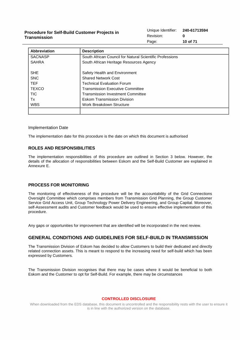
Abbreviation Description SACNASP SAHRA SHE SNC TEF TEXCO TIC Tx WBS
South African Council for Natural Scientific Professions South African Heritage Resources Agency Safety Health and Environment Shared Network Cost Technical Evaluation Forum Transmission Executive Committee Transmission Investment Committee Eskom Transmission Division Work Breakdown Structure
Implementation Date
The implementation date for this procedure is the date on which this document is authorised
ROLES AND RESPONSIBILITIES
The implementation responsibilities of this procedure are outlined in Section 3 below. However, the details of the allocation of responsibilities between Eskom and the Self-Build Customer are explained in Annexure E.
PROCESS FOR MONITORING
The monitoring of effectiveness of this procedure will be the accountability of the Grid Connections Oversight Committee which comprises members from Transmission Grid Planning, the Group Customer Service Grid Access Unit, Group Technology Power Delivery Engineering, and Group Capital. Moreover, self-Assessment audits and Customer feedback would be used to ensure effective implementation of this procedure.
Any gaps or opportunities for improvement that are identified will be incorporated in the next review.
GENERAL CONDITIONS AND GUIDELINES FOR SELF-BUILD IN TRANSMISSION
The Transmission Division of Eskom has decided to allow Customers to build their dedicated and directly related connection assets. This is meant to respond to the increasing need for self-build which has been expressed by Customers.
The Transmission Division recognises that there may be cases where it would be beneficial to both Eskom and the Customer to opt for Self-Build. For example, there may be circumstances
Procedure for Self-Build Customer Projects in Transmission
CONTROLLED DISCLOSURE When downloaded from the EDS database, this document is uncontrolled and the responsibility rests with the user to ensure it
is in line with the authorized version on the database.
Unique Identifier: 240-61713594 Revision: 0 Page: 11 of 71
where a Customer is in a more advantageous position than Eskom to build his/her connection assets and thus achieve efficiencies in the capital cost and/or connection timelines.
The detailed conditions governing self-build option are listed in Annexure A.
KEY PRINCIPLES
The principal reason for allowing Self-Build at the Transmission network level is to afford the Customer the opportunity to seek efficiencies in capital costs and timelines in connecting their plants or load to the grid.
The following principles shall apply in a self-build project:
• The Customer may apply to exercise the self-build option;
• The right of the Customer to opt for the self-build option must be balanced against the inalienable right of the National Transmission Company to protect the integrity and security of the shared Transmission System.
• The National Transmission Company shall determine the connection method and the point of connection for any generation or load project. While an IPP or load customer can request a modification to their connection method, the modification will only be allowable where it is technically and financially justifiable and adheres to the Grid Code, Eskom specifications and standards.
• The National Transmission Company shall take over the ownership of the self-built assets.
• In cases where the self-built assets do not comply to the applicable standards, the National Transmission Company reserves the right to refuse the energisation and connection of those assets to the shared network. Eskom shall in such cases request the Customer to rectify the identified defects in the self-built assets at the Customer’s expense. The Customer may request Eskom to correct the defects, in which case the scope of works to correct the defects shall be treated by Eskom as a recoverable project and the full cost thereof shall be recovered from the Customer in accordance with Eskom’s procedure for recoverable projects.
• The Self-Build option shall apply only to the dedicated Customer connection assets.
• The Self-Build option is intended for single-Customer projects and may not be used for groups of Customers.
• Any associated reinforcements required elsewhere on the Transmission system will not be eligible for self-build.
• The self-build assets shall be built to Eskom’s standards and specifications. This is
intended to protect the safety, integrity, and security of the Transmission system.
• Eskom will recover from the self-build Customer any inspection, testing, and supervision costs incurred in ensuring that the self-built assets are built to Eskom standards and specifications.
Procedure for Self-Build Customer Projects in Transmission
CONTROLLED DISCLOSURE When downloaded from the EDS database, this document is uncontrolled and the responsibility rests with the user to ensure it
is in line with the authorized version on the database.
Unique Identifier: 240-61713594 Revision: 0 Page: 12 of 71
• The self-build Customer must ensure that the use of scarce national resources such as line routes are well-thought through such that no barrier is placed on the future development of the network.
• To facilitate maintainability and compatibility with the existing Eskom plant, Customers are required to source their primary plant and secondary plant equipment from existing Eskom contract suppliers. The items of plant selected must be those on existing Eskom contracts.
• The Self-Build Customer takes full accountability for its own and its agents’ Safety, Health and Environmental (SHE) incidents during the duration of the self-build project.
APPLICATION FOR SELF-BUILD
A Customer electing to make use of the self-build option to construct his/her own connection-infrastructure to connect to the transmission grid for the purposes of an electricity supply connection (load customer) or to export electricity to the grid (as a generator), or both MUST do so in writing. The application for the self-build option will be managed in accordance with the Eskom Project Life Cycle Model (PLCM) via the Direct Customer Process.
The Customer will have two opportunities to apply for the self-build option:
1. At the time of the Customer’s initial application, the Customer may indicate a preference for
the self- build option which will then be provided-for in the scope outlined in the cost
estimate letter; or
2. After the cost estimate letter has been issued by Eskom, at the cost-estimate acceptance
stage, the Customer also has an opportunity to indicate his/her preference for self-build.
In the latter case above (i.e. option 2) a revised cost estimate will have to be issued to the Customer detailing a revised scope of works excluding the self-build scope of works, a revised cost estimate and a revised project schedule. This cost-estimate will now be referred to as the Self-Build Cost Estimate and it will only reflect the portion of the works that will still be executed by Eskom.
NB: The Customer’s request to exercise the self-build option has to be in writing (in both instances).
If the Customer indicates his/her Self-Build preference only at the budget quotation stage (BQ stage) then all negotiations with Eskom will have to start afresh.
THE SELF-BUILD PROCESS AND ITS LINKAGES WITH THE E SKOM QUOTATION AND ENVIRONMENTAL AUTHORISATION PROCESSES
The linkages of the self-build process with the established Eskom processes of Customer Quotations and Environmental Authorisation are depicted in the flow-diagrams below:
Figure 1: Customer Application Process (From initia l application up to BQ stage)

Procedure for Self-Build Customer Projects in Transmission
CONTROLLED DISCLOSURE When downloaded from the EDS database, this document is uncontrolled and the responsibility rests with the user to ensure it
is in line with the authorized version on the database.
Unique Identifier: 240-61713594 Revision: 0 Page: 13 of 71

Procedure for Self-Build Customer Projects in Transmission
CONTROLLED DISCLOSURE When downloaded from the EDS database, this document is uncontrolled and the responsibility rests with the user to ensure it
is in line with the authorized version on the database.
Unique Identifier: 240-61713594 Revision: 0 Page: 14 of 71
Figure 2: Customer Application Process (showing tou ch points between the various Parties in the Project Lifecycle)
Procedure for Self-Build Customer Projects in Transmission
CONTROLLED DISCLOSURE When downloaded from the EDS database, this document is uncontrolled and the responsibility rests with the user to ensure it
is in line with the authorized version on the database.
Unique Identifier: 240-61713594 Revision: 0 Page: 15 of 71
ALLOCATION OF RESPONSIBILITIES BETWEEN THE CUSTOME R AND ESKOM IN A SELF-BUILD PROJECT
Customer’s Responsibilities (Contestable works)
The following activities are considered contestable works and may be allocated to the Customer for
self-build:
• Route and site selection.
• Environmental Impact Assessment (EIA).
• Environmental Authorisation (EA).
• Route and site acquisition
• All other land development assessments required; applications, permits and statutory approvals.
• Land rights:
o Servitude and Title Deeds for HV lines and substations.
o Only land rights registered against the title deed of a property will be accepted.
o Servitude and Title Deeds for access roads and Control Plant cabling and repeater stations.
o The statutory approvals, permits and licenses required.
• Concept designs (subject to Eskom design requirements as explained in Annexures F, G, and K).
• Detailed design (subject to Eskom design requirements as explained in Annexures F, G, and K).
• Transmission line specifications for all line components
• Construction profiles for the Transmission line
• Construction method statements
• Equipment/material purchasing.
• Construction.
• Works and assets that are required by Eskom for system protection, communication and metering.
• Pre-commissioning tests.
• Site clean-up, disposal of waste, and anti-erosion works in accordance with the EIMP.
• The Customer is responsible to provide all the documentary proof to the Eskom Project Manager confirming that all the holding points’ tests (as specified in Annexure B) have been successfully passed

Procedure for Self-Build Customer Projects in Transmission
CONTROLLED DISCLOSURE When downloaded from the EDS database, this document is uncontrolled and the responsibility rests with the user to ensure it
is in line with the authorized version on the database.
Unique Identifier: 240-61713594 Revision: 0 Page: 16 of 71
Eskom’s Responsibilities (Monopoly Works)
The following activities are considered monopoly works and will be carried out by Eskom:
• Network Planning Report and/or Business Case Report, motivating the need for an asset to be created
• Network Planning shall influence and approve the preferred network concept solutions and decisions.
• The determination of the point of connection and the connection method (Network Planning Solution) subject to the Customer providing the load or generation information as requested by Eskom.
• All work related to upstream, shared, or existing assets and any associated upstream system reinforcements.
• Works and assets that cannot be safely and efficiently separated from the existing live system.
• Network operational control and switching activities.
• The outline specifications and requirements relating to sites, routes and wayleaves/servitudes.
• The Eskom standards to be used for High Voltage lines and substations.
• The verification of compliance with Eskom Standards for the concept and detailed design of the self-build connection assets.
• The verification of compliance with Eskom Standards during the construction phase at the holding points determined by Eskom.
• Leading Customer’s Control Plant contractors during the inspection, testing and commissioning of the newly constructed asset with final sign-off and acceptance as objective.
• Maintenance of the self-built assets after they have been successfully commissioned and their ownership having been transferred to Eskom.
CONNECTION CHARGES APPLICABLE TO SELF-BUILD CUSTOM ER PROJECTS
3.5.1 Costs Payable
The Self-Build Customer will be required to pay a Connection Charge that comprises the costs of the Eskom component of the works (i.e. the monopoly works) to be performed and all Eskom costs associated with the connection works.
The charges that make up the connection charge will be calculated in accordance with the principles set out below:
• The Eskom costs associated with the connection works. These costs include the Eskom
component of the works (i.e. the monopoly works), project development costs, the cost of
Procedure for Self-Build Customer Projects in Transmission
CONTROLLED DISCLOSURE When downloaded from the EDS database, this document is uncontrolled and the responsibility rests with the user to ensure it
is in line with the authorized version on the database.
Unique Identifier: 240-61713594 Revision: 0 Page: 17 of 71
supervision and inspection of the self-built assets to ensure compliance with technical and safety standards and procedures, plus, where applicable, the premium-supply charges.
• The premium-supply charges are only applicable in cases where the Customer has elected to apply for a connection that requires infrastructure that is more than that of a standard connection.
• All costs associated with the monopoly works shall be payable upfront. These will be provided through the quotation process (i.e. cost estimate and budget quotation letters) and will be based on estimated costs. A final reconciliation of costs will be done upon the completion of the project.
The final cost will be based on the actual costs incurred. Any shortfall will be payable by the Customer and any over-charging by Eskom will be refunded to the Customer by Eskom. However, any over-recovery by Eskom will only be refunded to the Customer after Eskom has taken over the self-built assets and after there has been a final reconciliation of costs.
• The connection charges associated with the monopoly works will be required to be paid at the time of accepting the budget quotation, unless a written and signed payment schedule has been agreed with Eskom.
• In the cases where Eskom needs to purchase long lead-time material for its component of the works, the Customer shall be obliged to pay the cost of such long lead-time material before Eskom can proceed with the monopoly works. This is meant to prevent Eskom from incurring any liability for such long-lead items’ costs.
• In the cases where construction will be carried out over an extended period of time, the Customer may be required to make part-payments for the phases of the construction before Eskom proceeds with the various phases.
• In cases where a payment schedule has been agreed with Eskom, the Customer may be required to provide an acceptable connection-charge guarantee at the time of accepting the budget quotation.
• The NTC may, for the purposes of providing for its future requirements, request the Self-Build Customer to build assets with greater capacity than it needs for its own purposes. In such cases, the NTC shall refund the Customer all the costs related to the greater capacity. The quantum of the refund will be based on a written agreement between the Customer and the NTC.
3.5.2 Sharing of the Dedicated Customer Assets
In the event when, at some point in the future, the self-built assets that were constructed in accordance with this procedure, become shared (i.e. in cases where, at some future point, other unrelated Customers utilise or benefit from the self-built assets or a portion of the self-built assets), the original Self-Build Customer will be refunded all or a portion of the capital costs incurred less accumulated depreciation.
The NTC and the Customer shall, at the time of concluding the connection and the use-of-system agreements, agree on the value of the self-built connection assets. In the event where an agreement is not reached between the two parties, the value of the connection assets shall be based on the lower of the actual costs and the NTC’s reasonable cost to do the same work (i.e. the least life cycle costs as determined by the NTC).
Procedure for Self-Build Customer Projects in Transmission
CONTROLLED DISCLOSURE When downloaded from the EDS database, this document is uncontrolled and the responsibility rests with the user to ensure it
is in line with the authorized version on the database.
Unique Identifier: 240-61713594 Revision: 0 Page: 18 of 71
Any rebate to the Customer shall take into consideration the following principles:
• The original cost, straight line depreciation, and remaining useful life of the assets.
• The NERSA Guidelines on Transmission connection charges.
3.5.3 Transfer of Ownership
The Customer shall, after successful commissioning, transfer full ownership of the self-built connection assets to the NTC, including all environmental authorisations, approvals and approved permits.
The assets shall be transferred to Eskom at cost and in accordance with the guideline in Annexure J.
The Self-Build Customer retains the defects liability for the transferred assets.
HOLDING POINTS APPLICABLE TO SELF-BUILD PROJECTS T O ASSURE COMPLIANCE WITH ESKOM STANDARDS AND SPECIFICATIONS
It is important to note that, in a self-build Customer project, the Customer assumes all the project risk and associated liabilities from the beginning of the project up until successful commissioning and handover of the constructed asset to Eskom. The holding points specified in this section are intended to provide assurance to Eskom that the prevailing Eskom Standards and specifications are adhered-to during the self-build project execution.
The holding points provide a mechanism for Eskom to inspect and test the works during the construction phase. This has the benefit of ensuring that any non-conformances are resolved as early as possible in the project life cycle.
A detailed checklist of holding points required by Eskom is specified in Annexure B.
AUTHORIZATION
This document has been seen and accepted by:
Designation / Stakeholder Division
Group Executive Transmission
Group Executive Group Customer Services
TEXCO Members Transmission
Grid Managers Transmission
The Head of the Grid Access Unit Group Customer Service
Key Customer Executives Group Customer Service

Procedure for Self-Build Customer Projects in Transmission
CONTROLLED DISCLOSURE When downloaded from the EDS database, this document is uncontrolled and the responsibility rests with the user to ensure it
is in line with the authorized version on the database.
Unique Identifier: 240-61713594 Revision: 0 Page: 19 of 71
Designation / Stakeholder Division
General Manager Group Technology – Power Delivery Engineering
Senior General Manager Group Technology – Engineering
General Managers Group Capital
REVISIONS
Date Rev. Compiler Remarks
26-March-2013 0.00 Mbulelo Kibido New Number and the Draft Procedure for Tx Self Build Projects
05-July-2013 0.16 Roy Estment. Version accepted by the Development Team
08-August-2013 0.17 Mbulelo Kibido Version influenced by TEXCO, GAU, and Group Technology
15-August-2013 1 Mbulelo Kibido Authorised Version
DEVELOPMENT TEAM
The following people were involved in the development of this document:
Archibold Mogokonyane - Group Capital Land Development,
Asanda Taylor, Transmission,
Bernard Magoro, Transmission System Operator,
Bheki Ntshangase, Transmission Grids,
Braam Groenewald, Group Technology,
Caswell Ndlhovu, Transmission Grid Planning;
Charles Kalima, Group Commercial,
Elliot Vilakazi, Group Commercial Land & Related Services,
Eric Shunmagum, Transmission AME,
Ernest Grunewald, Group Commercial Land & Related Services,
Harish Mohabir, Transmission AME,
Johan Bornman, Group Capital PDP,
John Geeringh, Eskom Real Estate ( ERE): Land Development,,
Juan La Grange, Transmission Office of the GE,
Jurie Groenewald, Group Capital PDD,
Leslie Naidoo, Transmission Grid Planning,
Malesela Sekhasimbe, Group Commercial,
Procedure for Self-Build Customer Projects in Transmission
CONTROLLED DISCLOSURE When downloaded from the EDS database, this document is uncontrolled and the responsibility rests with the user to ensure it
is in line with the authorized version on the database.
Unique Identifier: 240-61713594 Revision: 0 Page: 20 of 71
Mansoor Barday, Distribution Division,
Mmamie Kodisang, Eskom Transmission,
Mutenda Tshipala, Group Customer Service,
Philip Wahl, Distribution Western Cape OU,
Phineas Tlhatlhetji, Group Technology Substation Design,
Prince Kara, Group Technology, PTM&C,
Ray Asalan, Distribution Division,
Riaz Vajeth, Group Technology Line Design,
Richard Chinzvende, Transmission Grids,
Roger Cormack, Group Technology HV Plant,
Roy Estment, Transmission Grid Planning,
Solly Matlala, Transmission BIPM,
Thys Bower, Group Technology PTM&C,
Wolfgang Bohmer, Group Customer Services Grid Access Unit,
ACKNOWLEDGEMENTS
The contribution of the development team and their generosity in dedicating their time to this project is acknowledged and greatly appreciated.
Procedure for Self-Build Customer Projects in Transmission
CONTROLLED DISCLOSURE When downloaded from the EDS database, this document is uncontrolled and the responsibility rests with the user to ensure it
is in line with the authorized version on the database.
Unique Identifier: 240-61713594 Revision: 0 Page: 21 of 71
ANNEXURE A:
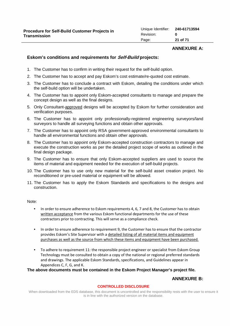
Eskom’s conditions and requirements for Self-Build projects:
1. The Customer has to confirm in writing their request for the self-build option.
2. The Customer has to accept and pay Eskom’s cost estimate/re-quoted cost estimate.
3. The Customer has to conclude a contract with Eskom, detailing the conditions under which the self-build option will be undertaken.
4. The Customer has to appoint only Eskom-accepted consultants to manage and prepare the concept design as well as the final designs.
5. Only Consultant-approved designs will be accepted by Eskom for further consideration and verification purposes.
6. The Customer has to appoint only professionally-registered engineering surveyors/land surveyors to handle all surveying functions and obtain other approvals.
7. The Customer has to appoint only RSA government-approved environmental consultants to handle all environmental functions and obtain other approvals.
8. The Customer has to appoint only Eskom-accepted construction contractors to manage and execute the construction works as per the detailed project scope of works as outlined in the final design package.
9. The Customer has to ensure that only Eskom-accepted suppliers are used to source the items of material and equipment needed for the execution of self-build projects.
10. The Customer has to use only new material for the self-build asset creation project. No reconditioned or pre-used material or equipment will be allowed.
11. The Customer has to apply the Eskom Standards and specifications to the designs and construction.
Note:
• In order to ensure adherence to Eskom requirements 4, 6, 7 and 8, the Customer has to obtain
written acceptance from the various Eskom functional departments for the use of these
contractors prior to contracting. This will serve as a compliance check.
• In order to ensure adherence to requirement 9, the Customer has to ensure that the contractor
provides Eskom’s Site Supervisor with a detailed listing of all material items and equipment
purchases as well as the source from which these items and equipment have been purchased.
• To adhere to requirement 11: the responsible project engineer or specialist from Eskom Group
Technology must be consulted to obtain a copy of the national or regional preferred standards
and drawings. The applicable Eskom Standards, specifications, and Guidelines appear in
Appendices C, F, G, and K.
The above documents must be contained in the Eskom Project Manager’s project file.
ANNEXURE B:
Procedure for Self-Build Customer Projects in Transmission
CONTROLLED DISCLOSURE When downloaded from the EDS database, this document is uncontrolled and the responsibility rests with the user to ensure it
is in line with the authorized version on the database.
Unique Identifier: 240-61713594 Revision: 0 Page: 22 of 71
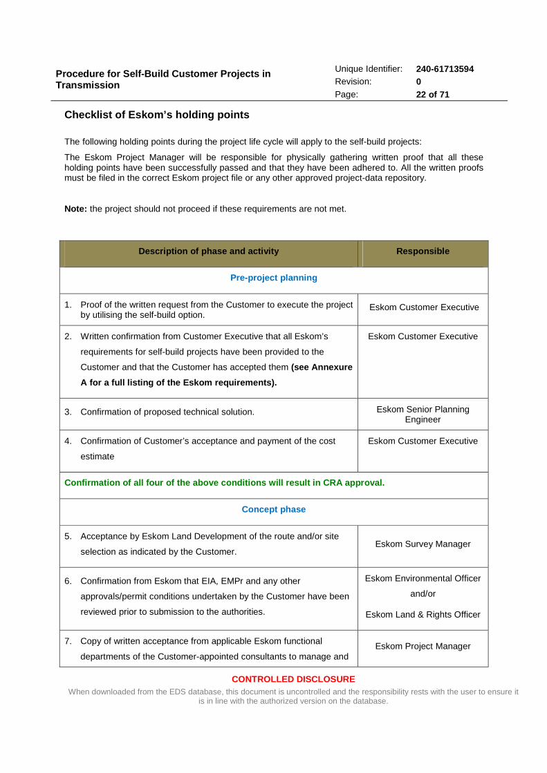
Checklist of Eskom’s holding points
The following holding points during the project life cycle will apply to the self-build projects:
The Eskom Project Manager will be responsible for physically gathering written proof that all these holding points have been successfully passed and that they have been adhered to. All the written proofs must be filed in the correct Eskom project file or any other approved project-data repository.
Note: the project should not proceed if these requirements are not met.
Description of phase and activity Responsible
Pre-project planning
1. Proof of the written request from the Customer to execute the project by utilising the self-build option.
Eskom Customer Executive
2. Written confirmation from Customer Executive that all Eskom’s
requirements for self-build projects have been provided to the
Customer and that the Customer has accepted them (see Annexure
A for a full listing of the Eskom requirements).
Eskom Customer Executive
3. Confirmation of proposed technical solution. Eskom Senior Planning Engineer
4. Confirmation of Customer’s acceptance and payment of the cost
estimate
Eskom Customer Executive
Confirmation of all four of the above conditions wi ll result in CRA approval.
Concept phase
5. Acceptance by Eskom Land Development of the route and/or site
selection as indicated by the Customer. Eskom Survey Manager
6. Confirmation from Eskom that EIA, EMPr and any other
approvals/permit conditions undertaken by the Customer have been
reviewed prior to submission to the authorities.
Eskom Environmental Officer
and/or
Eskom Land & Rights Officer
7. Copy of written acceptance from applicable Eskom functional
departments of the Customer-appointed consultants to manage and Eskom Project Manager

Procedure for Self-Build Customer Projects in Transmission
CONTROLLED DISCLOSURE When downloaded from the EDS database, this document is uncontrolled and the responsibility rests with the user to ensure it
is in line with the authorized version on the database.
Unique Identifier: 240-61713594 Revision: 0 Page: 23 of 71
Description of phase and activity Responsible
prepare the concept design as well as the final designs. Ensure that
the copy of written acceptance to the Customer is filed as well.
(See Condition 4 in Annexure A).
8. Copy to the Customer of Eskom’s written acceptance of the
Customer-appointed engineering surveyors/land surveyors to handle
all surveying functions and other approvals.
(See Condition 6 in Annexure A.)
Eskom Survey Manager
9. Copy to the Customer of Eskom’s written acceptance of the
Customer-appointed environmental consultants to handle all
environmental functions and other approvals.
(See Condition 7 in Annexure A.)
Eskom Environmental Officer
10. Confirmation that the Customer’s concept design has been
accepted/supported by the relevant DRT. Eskom Project Manager
Confirmation of all above conditions will result in DRA approval.
Definition phase
11. Confirmation that the Customer’s Final Design Package is accepted
/ supported. Eskom Project Manager
12. Copy to the Customer of Eskom Project Management’s written
acceptance of the Customer-appointed construction contractors
(power and control plant contractors).
(See Condition 8 in Annexure A.)
Eskom Project Manager
Confirmation of above condition will result in ERA approval.
Execution Phase 1 (prior to commencement of constru ction)
13. Review by Eskom of the approval / permit conditions prior to and
during the construction phase – checking that all legal requirements
to commence construction have been adhered to, which may include
Eskom Acquisition Advisor
AND

Procedure for Self-Build Customer Projects in Transmission
CONTROLLED DISCLOSURE When downloaded from the EDS database, this document is uncontrolled and the responsibility rests with the user to ensure it
is in line with the authorized version on the database.
Unique Identifier: 240-61713594 Revision: 0 Page: 24 of 71
Description of phase and activity Responsible
all or some of the following but are not limited to:
⋅ Landowners’ contracts / registration in Deeds Office
⋅ Environmental Authorisations – DEA
⋅ DEA (Province)
⋅ Local and Provincial Authorities
⋅ SAHRA and any provincial Heritage Authorities such as
HWC
⋅ Telkom, Neotel
⋅ Roads – national (SANRAL), provincial and local road
agencies
⋅ DWA
⋅ Transnet
⋅ ESKOM, TELKOM & Municipalities – crossings of other
power lines and services
⋅ Pipeline authorities: crossings or close proximity to
pipelines
⋅ Mining authorities: underground and open cast mining
activities
⋅ Wind farms: proximity to these
⋅ Aviation/Airport authority: proximity to aircraft
approaches
⋅ Other approvals / permits as may be required by
legislation such as water use licences, tree-cutting
permits, borrow pits, etc.
Eskom Environmental Advisor
14. Confirmation that the project kick-off meeting has taken place and all
Eskom pre-construction requirements have been adhered to Eskom Project Manager
Confirmation of all the above requirements will all ow the Customer’s contractor to commence
Procedure for Self-Build Customer Projects in Transmission
CONTROLLED DISCLOSURE When downloaded from the EDS database, this document is uncontrolled and the responsibility rests with the user to ensure it
is in line with the authorized version on the database.
Unique Identifier: 240-61713594 Revision: 0 Page: 25 of 71
Description of phase and activity Responsible
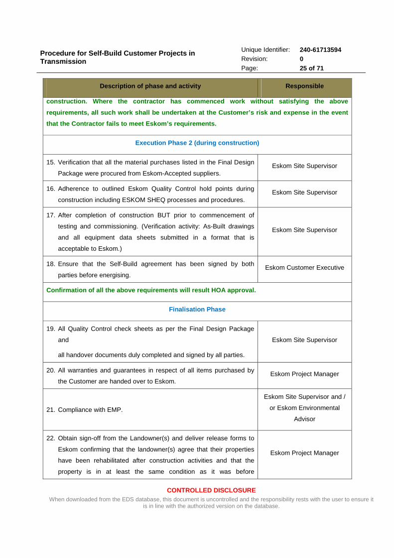
construction. Where the contractor has commenced wo rk without satisfying the above
requirements, all such work shall be undertaken at the Customer’s risk and expense in the event
that the Contractor fails to meet Eskom’s requireme nts.
Execution Phase 2 (during construction)
15. Verification that all the material purchases listed in the Final Design
Package were procured from Eskom-Accepted suppliers. Eskom Site Supervisor
16. Adherence to outlined Eskom Quality Control hold points during
construction including ESKOM SHEQ processes and procedures. Eskom Site Supervisor
17. After completion of construction BUT prior to commencement of
testing and commissioning. (Verification activity: As-Built drawings
and all equipment data sheets submitted in a format that is
acceptable to Eskom.)
Eskom Site Supervisor
18. Ensure that the Self-Build agreement has been signed by both
parties before energising. Eskom Customer Executive
Confirmation of all the above requirements will res ult HOA approval.
Finalisation Phase
19. All Quality Control check sheets as per the Final Design Package
and
all handover documents duly completed and signed by all parties.
Eskom Site Supervisor
20. All warranties and guarantees in respect of all items purchased by
the Customer are handed over to Eskom. Eskom Project Manager
21. Compliance with EMP.
Eskom Site Supervisor and /
or Eskom Environmental
Advisor
22. Obtain sign-off from the Landowner(s) and deliver release forms to
Eskom confirming that the landowner(s) agree that their properties
have been rehabilitated after construction activities and that the
property is in at least the same condition as it was before
Eskom Project Manager

Procedure for Self-Build Customer Projects in Transmission
CONTROLLED DISCLOSURE When downloaded from the EDS database, this document is uncontrolled and the responsibility rests with the user to ensure it
is in line with the authorized version on the database.
Unique Identifier: 240-61713594 Revision: 0 Page: 26 of 71
Description of phase and activity Responsible
construction started
23. Receipt of the As-Built design package from the Customer Eskom Project Manager
Confirmation of all the above requirements will res ult in FRA approval.
Procedure for Self-Build Customer Projects in Transmission
CONTROLLED DISCLOSURE When downloaded from the EDS database, this document is uncontrolled and the responsibility rests with the user to ensure it
is in line with the authorized version on the database.
Unique Identifier: 240-61713594 Revision: 0 Page: 27 of 71
ANNEXURE C:
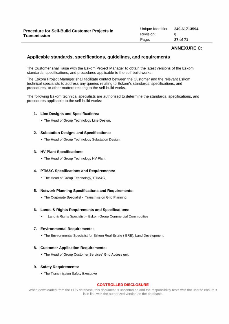
Applicable standards, specifications, guidelines, a nd requirements
The Customer shall liaise with the Eskom Project Manager to obtain the latest versions of the Eskom standards, specifications, and procedures applicable to the self-build works.
The Eskom Project Manager shall facilitate contact between the Customer and the relevant Eskom technical specialists to address any queries relating to Eskom’s standards, specifications, and procedures, or other matters relating to the self-build works. The following Eskom technical specialists are authorised to determine the standards, specifications, and procedures applicable to the self-build works:
1. Line Designs and Specifications:
• The Head of Group Technology Line Design,
2. Substation Designs and Specifications:
• The Head of Group Technology Substation Design,
3. HV Plant Specifications:
• The Head of Group Technology HV Plant,
4. PTM&C Specifications and Requirements:
• The Head of Group Technology, PTM&C,
5. Network Planning Specifications and Requirements :
• The Corporate Specialist - Transmission Grid Planning
6. Lands & Rights Requirements and Specifications:
• Land & Rights Specialist – Eskom Group Commercial Commodities
7. Environmental Requirements:
• The Environmental Specialist for Eskom Real Estate ( ERE): Land Development,
8. Customer Application Requirements:
• The Head of Group Customer Services’ Grid Access unit
9. Safety Requirements:
• The Transmission Safety Executive
Procedure for Self-Build Customer Projects in Transmission
CONTROLLED DISCLOSURE When downloaded from the EDS database, this document is uncontrolled and the responsibility rests with the user to ensure it
is in line with the authorized version on the database.
Unique Identifier: 240-61713594 Revision: 0 Page: 28 of 71
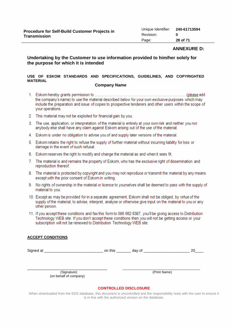
ANNEXURE D:
Undertaking by the Customer to use information prov ided to him/her solely for the purpose for which it is intended USE OF ESKOM STANDARDS AND SPECIFICATIONS, GUIDELIN ES, AND COPYRIGHTED MATERIAL
ACCEPT CONDITIONS Signed at ____________________________ on this _______ day of ______________________ 20____ ______________________________________ _________________________________________ (Signature) (Print Name) (on behalf of company)
Company Name

Procedure for Self-Build Customer Projects in Transmission
CONTROLLED DISCLOSURE When downloaded from the EDS database, this document is uncontrolled and the responsibility rests with the user to ensure it
is in line with the authorized version on the database.
Unique Identifier: 240-61713594 Revision: 0 Page: 29 of 71
ANNEXURE E:
Details of Customer’s and Eskom’s Responsibilities during a Transmission Self-Build Project
1 General Customer’s Responsibilities:
The Customer or his/her Agent must ensure the following:
1.1 The completion of the Eskom application form, detailing the requirements.
1.2 The provision for PTM&C and energy metering requirements in the scope of works
1.3 The appointment of design engineers who will be responsible for the design and the presentation
of the concept and detailed design documents. These designers must be Eskom-Accepted
consultants, as they will be responsible for design and construction management. To protect
Eskom’s interests in a Transmission self- build scheme agreement, the design to be used must
be accepted/supported by the Design Review Team prior to the commencement of any
construction work. This is intended to ensure that the network is constructed to Eskom’s
standards and specifications in order that the new assets can be
maintained satisfactorily by Eskom after construction.
1.4 The appointment of a negotiator or negotiation consultant to assist with the route acquisition
process.
1.5 The appointment of an engineering surveyor / land surveyor who is responsible for the
cadastral/registration survey. The surveyor must be registered with Plato.
1.6 The appointment of an environmental consultant to conduct the environmental process. This
consultant must be formally registered and/or accepted by Government to conduct EIAs.
1.7 The appointment of relevant Town and Regional Planners for relevant municipal approvals.
1.8 The appointment of the contractor that will do the construction. The construction contractor must
be an Eskom-accepted/accredited contractor. Such a contractor will therefore be well versed and
knowledgeable in the construction of Transmission assets.
1.9 The preparation of a tax invoice for submission to Eskom in order to effect any capital allowance
payment (if applicable).
1.10 The development of Health & Safety specifications and the approval of the contractor’s Health &
Safety Plan.
1.11 Prepare the power and control plant for testing and commissioning.

Procedure for Self-Build Customer Projects in Transmission
CONTROLLED DISCLOSURE When downloaded from the EDS database, this document is uncontrolled and the responsibility rests with the user to ensure it
is in line with the authorized version on the database.
Unique Identifier: 240-61713594 Revision: 0 Page: 30 of 71
1.12 Assist Eskom with the testing and commissioning activities.
1.13 Timely completion of the project – Eskom absolves itself from any liability for the late delivery of
any assets being constructed by the Customer.
1.14 The Customer must provide a one–year warranty against poor workmanship to Eskom.
The responsibilities of the resources/Consultants/Contractors/agents as appointed by the Customer are
as detailed in section 2 below:
2 Land Surveying, Land Acquisition and Environmental – Customer
Responsibilities:
The Customer must appoint the following parties for land development activities:
• A professionally-registered surveyor who is responsible for lands and rights, the engineering
survey and geographic mapping and obtaining of statutory approvals.
• A negotiator to assist with the negotiations associated with the acquisition of a servitude.
• A Government-approved environmental consultant who is responsible for obtaining
environmental authorisations.
• A professional land surveyor who is responsible for the cadastral survey.
• A Conveyancer who is responsible for the registration of servitudes or the transfer of land.
The responsibilities related to each of these environmental activities will be further described in the
following sections.
3 Lands and Rights - Customer Responsibilities:
• Route selection
o Approval of route by Eskom Land Development and Senior Project Engineer.
o Ensuring that the route plan adheres to the Eskom Standards.

Procedure for Self-Build Customer Projects in Transmission
CONTROLLED DISCLOSURE When downloaded from the EDS database, this document is uncontrolled and the responsibility rests with the user to ensure it
is in line with the authorized version on the database.
Unique Identifier: 240-61713594 Revision: 0 Page: 31 of 71
o The route plan must include the final route and substation site, as well as any
switching station site if required, all access roads, all road / rail crossings with the
kilometre reading, cadastral boundaries and property descriptions, a co-ordinated list
of all the bend points on the route and affected servitudes.
Note: the access road, from the main tar road up to the Eskom yard, has to be
accepted/supported by Eskom Project Manager. This access road to the site must be suitable
for a “sedan two-wheel drive vehicle”, and must be wide enough and have the correct
carrying capacity to accommodate construction vehicles/low-bed trucks (including those used
for transporting transformers). The access road must also be surveyed as a servitude and
registered in the Deeds Office as an access road in favour of Eskom, and the cost of this
registration is for the Customer's account.
o The route must follow the shortest possible distance and use minimal bends to
minimise cost and be done under the guidance of the Eskom Standards.
o The route has to take into account that dams and wetlands must be avoided where
possible and feasible
• The EIA has to include the soil resistivity tests for part of the substation and switching site
selection process as well as the proposed bend points to ensure the site’s suitability
• Eskom must approve any changes required to its networks (e.g. line deviations) to
accommodate the Customer line or substation.
• All statutory approvals and licences must be obtained that are required for the complete life
cycle of the asset. Specific caution should be taken where limited approval is granted, such
as instances where Eskom could be liable for relocation costs at any stage.
• Obtaining the schedule of owners:
o This list must include the property description, registered owner, contact person,
postal address, telephone/fax number and special requests/conditions.
o All communication with property owners must be recorded and listed per property
owner.
• Schedule of mineral rights holders – the Mineral and Petroleum Resources Development Act,
2002. The Customer has to give Eskom all the details surrounding mineral rights and mineral
rights holders. The Customer has to negotiate and supply land rights to Eskom that are void
Procedure for Self-Build Customer Projects in Transmission
CONTROLLED DISCLOSURE When downloaded from the EDS database, this document is uncontrolled and the responsibility rests with the user to ensure it
is in line with the authorized version on the database.
Unique Identifier: 240-61713594 Revision: 0 Page: 32 of 71
of the cost risk for the relocation of services at any stage. These conditions have to be
contained in the notarial deed of servitude.
• Consideration and compensation for land rights – the consideration payable for the land
rights acquired must be based on the principles set out in the Expropriation Act and must
furthermore be in accordance with the Eskom Consideration and Compensation Standard
(EST 32-844). Any additional payments or “sweeteners” paid to landowners must be made
through separate agreement and may not be reflected in the Deed of Servitude as part of the
price.
• The option has to be included in the agreement to register the servitude/s in favour of Eskom
with Eskom servitude conditions of access, construction and maintenance at the time of
registration and the option to cede to Eskom with Eskom’s servitude conditions of
maintenance.
• Exercise options / transfer of ownership to Eskom
o Ensure that the Eskom ceding clause and Eskom conditions are included – see note
below.
o It must be noted that the Customer is liable for all costs, damages and rework should
any land parcel be missed in the process of obtaining rights for Eskom.
o The registration process in general terms must occur for the route and in general or
specific terms for the substation, and within 6 months of construction the route must
be defined in specific terms in the Deeds Office.
o Note: although it is a fairly simple notarial process to cede a servitude from one entity
to another entity, one item which should be considered is the fact the Eskom is
exempt from some of the Regulations of Act 70 of 1970, section 6 (1) (a) and 6(1)(a).
This in effect means that Eskom need not acquire approval from the Minister of
Agriculture for the registration of a servitude exceeding a width of 15 metres or an
area exceeding 225 square metres, if a private person acquires a servitude in a right
which exceeds the width and area mentioned. Therefore a site exceeding 15 m x
15 m or a line servitude required for an area wider than 7.5 m on either side of the
centre line, does require Ministerial approval. Therefore there is not much which they
could do as far as HV sites and HV line servitudes are concerned. They will need
Procedure for Self-Build Customer Projects in Transmission
CONTROLLED DISCLOSURE When downloaded from the EDS database, this document is uncontrolled and the responsibility rests with the user to ensure it
is in line with the authorized version on the database.
Unique Identifier: 240-61713594 Revision: 0 Page: 33 of 71
Ministerial approval for most servitudes. Accordingly, it could be in the interests of all
concerned that the servitude should include the option of being registered on behalf
of Eskom from the outset as obtaining approval from the Minister could take an
extremely long time.
4 Environmental Authorisation Process – Customer Resp onsibilities:
A procedurally sound environmental impact assessment must be conducted for the HV power line and
substation, which must comply with the requirements of the National Environmental Management Act,
1998 (Act No. 107 of 1998), as amended, and the Environmental Impact Assessment Regulations, 2010,
addressing the project as a whole and meeting all relevant legal and procedural requirements.
a) Submit the Basic Assessment Report/ Environmental Impact Assessment Report to the relevant
competent environmental authority for authorisation.
b) Consult Eskom (Land Development) as an interested and affected party during the BAR/ EIA
phase.
c) Forward the original submission, Environmental Authorisation (EA), Construction Environmental
Management Plan (EMP), Maintenance EMP and Decommissioning EMP to Eskom.
• Eskom has to be consulted regarding the Maintenance and Decommissioning EMP prior to
their submission to DEA prior to initial submission or to finalisation after EA.
d) Eskom can request all other correspondence concerning the project.
e) A list of all interested and affected parties (electronic format) should be made available to Eskom
on completion of the project.
f) All legal conditions, including EA conditions and conditions contained in the approvals granted by
the relevant authorities (DEA, SAHRA (HWC), local and provincial authorities, DWA, etc.) must be
adhered to.
g) All environmental legal liabilities and claims arising from the activities of the Customer and any of
the Customer’s subcontractors shall be for the Customer’s expense.
5 Engineering survey or design consultant where appli cable (Customer-appointed)
a) Submits all records to Eskom including the following:

Procedure for Self-Build Customer Projects in Transmission
CONTROLLED DISCLOSURE When downloaded from the EDS database, this document is uncontrolled and the responsibility rests with the user to ensure it
is in line with the authorized version on the database.
Unique Identifier: 240-61713594 Revision: 0 Page: 34 of 71
· Profiles, tower positions, line and pegging information in ASCII format and CAD
diagrams.
· All field surveying and calculations necessary to complete the work.
· Any wayleave documentation that was required in any changes to 11kV, 22kV, or other
affected power lines, and all the survey work relating to such changes.
· Profiles and drawings (scale as per Eskom specifications) with the necessary topography
indicated (refer to the standard listed in Annexure C).
· All templated profiles have to be submitted in PLSCAD format for soft copy and as hard
copy.
· All co-ordinate data, including as-pegged data, setting out data, etc.
· Adherence to the as-built template requirements
b) Civil engineering plans and designs that need approval at municipal level in terms of the
municipal building plan submissions have to be part of the responsibility of the Customer’s
consultant.
c) Labelling of the line has to be done both in the field and on the poles, and this labelling must be
reflected on the plans.
d) No handover may take place until all statutory approvals and legal requirements for the project
have been obtained and checked by Eskom; and no construction may start until all the legal
requirements are met and have been checked by Eskom.
· Soft and hard copies of all statutory approvals have to be submitted.
· All hard copies of plans must have the approval stamp on them.
· Relevant approvals include but are not restricted to: the local authority, Telkom, Neotel,
Roads, Rail, Water Affairs, etc.
6 Cadastral / registration survey – Customer Responsi bilities
a) Registration surveys shall be conducted for the subdivision of the substation site (either by
subdivision or registration of a servitude), all as per the Land Survey Act No. 8 of 1997.
· Registration surveys, including the accepted/supported diagrams, must be completed.
Procedure for Self-Build Customer Projects in Transmission
CONTROLLED DISCLOSURE When downloaded from the EDS database, this document is uncontrolled and the responsibility rests with the user to ensure it
is in line with the authorized version on the database.
Unique Identifier: 240-61713594 Revision: 0 Page: 35 of 71
· Registration copies of accepted/supported diagrams from the Surveyor-General and title
deeds for the line and substation have to be delivered to Eskom Land Development by
registered post or by hand.
b) The language used in the diagrams and title deeds must be English or Afrikaans, as specified by
the individual landowners.
c) Eskom will require an abbreviated hard copy x 1 and a digital copy of the survey records – co-
ordinate list, working plan and report, together with a digital copy of each diagram for our GIS
data base. One photocopy each of statutory approvals and local authority endorsements required
for the registration process must accompany the hard copies of the survey record.
d) Insurance / Claim Event – contravention of any provision of the Land Survey Act 8/1997 in
connection with a cadastral survey – period following the completion of the whole of the services
or earlier termination: as specified in the Land Survey Act No. 8 of 1997.
7 Geographic mapping – Customer Responsibilities
a) The standards for the submission for any drawings or spatial data are listed under the Geographic
Mapping Standards in Annexure D, and must be adhered to.
b) Both the hard copy and electronic format must be provided for all submissions.
c) All co-ordinates have to be in WGS 84 and in the correct Lo.
d) The acceptable formats are CAD format i.e. Microstation to AutoCAD. Shape files will also be
required (.dwd, .dgn, shape formats). The conductor types, tower types and numbering of towers
in field are required too.
e) Route plans have to be at the largest sensible scale. 1:5 000, 1:10000 or 1:25 000 (maximum) or
whichever larger scale is suitable for the plans. Odd scales will not be accepted.
f) An aerial photography backdrop has to be provided if available.
g) Raster / topographic backdrop has to be provided, i.e. any additional information which assists
with the readability of the plans.
h) All templated profiles (design drawings) have to be submitted in PLSCAD (.bak) format as well as
three hard copy plans, of which at least one must be a Sepia copy signed off by the design
engineer.

Procedure for Self-Build Customer Projects in Transmission
CONTROLLED DISCLOSURE When downloaded from the EDS database, this document is uncontrolled and the responsibility rests with the user to ensure it
is in line with the authorized version on the database.
Unique Identifier: 240-61713594 Revision: 0 Page: 36 of 71
i) Besides the design drawings, the As-Built drawings and GPS co-ordinates of all support
structures must be submitted once the project has been constructed.
j) The proposed schematic layout (single line diagram) has to be provided.
k) Commissioning dates or time lines should be supplied.
l) Assist with updating the electrical diagrams.
8 Lands & Rights Conveyance – Customer Responsibiliti es
a) A Conveyancer must be appointed to handle the conveyance work.
b) It should be noted that no delegation of authority is possible for the assigning of Eskom’s rights to
a third party. Therefore all draft deeds must be submitted to Eskom for scrutiny and signing –in
general and in specific terms.
c) If the landowner specifies the requirement that his/her attorney is to be used, in such cases both
Eskom’s and the landowner’s attorneys will handle the conveyance of that land parcel.
d) Registration in general terms, or in specific terms for the substation where the accepted diagrams
are obtained from the Surveyor General’s office, has to begin as soon as possible and the deeds
transfer must be completed within 8 months of exercising the options (barring unforeseen
circumstances with landowners, which must be substantiated and documented).
e) All costs have to be borne by the Customer.
9 Design Engineer / Consultant – Customer Responsibil ities
The Customer’s design engineer / Consultant is responsible for the following:
• To ensure that the scope of the works covers all the assets required to make the Customer
connection complete; including energy metering requirements.
• Presenting the concept design, final design, and execution plan at the Design Review Team
(DRT) as arranged by the responsible Eskom project engineer. Should there be any action
items following the DRT meeting, the consultant shall be required to make the suggested
changes and present the project again. The concept design report must be made available
two weeks prior to the DRT. An outline of the required content of this report for substation
and lines projects respectively is shown in Table 3.
• Providing costing for the project.

Procedure for Self-Build Customer Projects in Transmission
CONTROLLED DISCLOSURE When downloaded from the EDS database, this document is uncontrolled and the responsibility rests with the user to ensure it
is in line with the authorized version on the database.
Unique Identifier: 240-61713594 Revision: 0 Page: 37 of 71
• Submitting the final design document (FDD) to Eskom DRT for review. The following must be
submitted: 1 printed A4 FDD, 1 copy of all drawings printed to scale, CD containing electronic
copies of all documents in the original format, not in a *pdf format.
• Eskom DRT only accepts the FDD, it does not approve it. The Eskom Project Engineer
merely accepts and confirms that the design has been done in line with the Eskom Standards
as listed in Annexure A. Eskom expects the FDD to be approved by the consultant’s
professional engineer, resting the final professional responsibility for the design with the
consultant. The consultant will be liable for the soundness of the design for the entire lifetime
of the designed asset. After reviewing, if there are no changes to be made, the FDD will be
made available by Eskom DRT to the Eskom Project Manager. Note that all drawings must
be established by using the Microstation Software package [*.dgn format] or latest Eskom-
compatible software.
• The required content of final design documents for substation and line projects respectively is
shown in Table 4.
• Any design changes made during construction must be communicated to ESKOM and
reflected in the as-built documents.
• Arranging to have the final constructed asset’s as-built drawings signed-off before handing
them over to Eskom.

Procedure for Self-Build Customer Projects in Transmission
CONTROLLED DISCLOSURE When downloaded from the EDS database, this document is uncontrolled and the responsibility rests with the user to ensure it
is in line with the authorized version on the database.
Unique Identifier: 240-61713594 Revision: 0 Page: 38 of 71
10 Table 3: Concept design report requirements – Subst ations and Lines
Concept design for HV substation projects Concept design for HV lines projects
· Conducted assessments: o Environmental Impact o All national, applicable provincial and local bodies, including but not limited to the –
� DEA; � DEA&PDEA (Province); � SAHRA (South African Heritage Resources Agency); � Provincial Heritage – e.g. HWC (Western Cape); � DAFF (Department of Forestry and Fisheries); � MTO (Mountain to Ocean – Western Cape forestry) and others; � Provincial Parks, e.g. Cape Nature (Western Cape); � DWAF (Department of Water Affairs); � Local authorities, including Aviation and Rail authorities � Specialist studies as required by the DEA such as for avifauna; � Others as required.
o Soil resistivity o Other assessments as deemed fit / factors influencing the overall design; including wind,
pollution monitoring, geotechnical investigations, vandalism, bird, fire, lightning and icing studies.
· Bill of materials (highlighting long lead-time equipment)
· Conducted assessments: o Air-wave communications /
reception availability o Security o Pollution level
· Design philosophy covering the following:
o Station electric diagrams / operating diagrams
o Conceptual layout drawings o Earthing requirements o Surge / lightning protection o Equipment and conductor
ratings considering loading and future fault levels
· Other supporting documentation
· Design philosophy covering the following: o Executive summary o Scope o Power line route o Conductor and insulators o Wind loading used on structure
designs o Structure designs o Foundation designs o Earthing and shielding design o Measures to reduce environmental
impact o Other assessments as deemed fit /
factors influencing the overall design; including wind, pollution monitoring, geotechnical studies, vandalism, bird, fire, lightning and icing studies.
· Structure drawings
· Foundation drawings
· Other supporting documentation
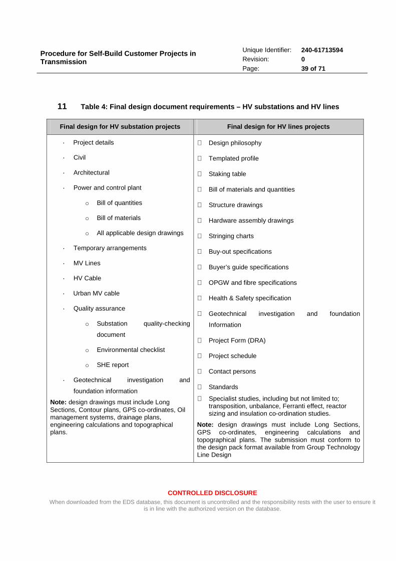
Procedure for Self-Build Customer Projects in Transmission
CONTROLLED DISCLOSURE When downloaded from the EDS database, this document is uncontrolled and the responsibility rests with the user to ensure it
is in line with the authorized version on the database.
Unique Identifier: 240-61713594 Revision: 0 Page: 39 of 71
11 Table 4: Final design document requirements – HV su bstations and HV lines
Final design for HV substation projects Final design for HV lines projects
· Project details
· Civil
· Architectural
· Power and control plant
o Bill of quantities
o Bill of materials
o All applicable design drawings
· Temporary arrangements
· MV Lines
· HV Cable
· Urban MV cable
· Quality assurance
o Substation quality-checking
document
o Environmental checklist
o SHE report
· Geotechnical investigation and
foundation information
Note: design drawings must include Long Sections, Contour plans, GPS co-ordinates, Oil management systems, drainage plans, engineering calculations and topographical plans.
⋅ Design philosophy
⋅ Templated profile
⋅ Staking table
⋅ Bill of materials and quantities
⋅ Structure drawings
⋅ Hardware assembly drawings
⋅ Stringing charts
⋅ Buy-out specifications
⋅ Buyer’s guide specifications
⋅ OPGW and fibre specifications
⋅ Health & Safety specification
⋅ Geotechnical investigation and foundation
Information
⋅ Project Form (DRA)
⋅ Project schedule
⋅ Contact persons
⋅ Standards
⋅ Specialist studies, including but not limited to; transposition, unbalance, Ferranti effect, reactor sizing and insulation co-ordination studies.
Note: design drawings must include Long Sections, GPS co-ordinates, engineering calculations and topographical plans. The submission must conform to the design pack format available from Group Technology Line Design
Procedure for Self-Build Customer Projects in Transmission
CONTROLLED DISCLOSURE When downloaded from the EDS database, this document is uncontrolled and the responsibility rests with the user to ensure it
is in line with the authorized version on the database.
Unique Identifier: 240-61713594 Revision: 0 Page: 40 of 71
11.1 Contractor’s responsibilities (Customer-appoin ted)
· The contractor should not commence any construction work unless he/she is in possession of
and Eskom-accepted final design document (FDD).
· The contractor must provide to the Eskom Site Supervisor a list of all material to be used and the
suppliers from which these materials have been procured.
· The contractor must provide to the Eskom Site Supervisor a detailed construction programme,
clearly indicating all quality control hold points as specified by Eskom.
· The contractor is responsible for safety checks and acceptance, and the development of a Health
& Safety Plan to be accepted by the Customer/consultant.
· The contractor is responsible for the installation of control plant panels with associated cabling
and the termination of the cables.
· Submission of as-built drawings after construction, which will contain at least but are not limited to
the following:
- Support structure labels numbers.
- Final co-ordinates of all support structures and in the case of a cable, the position of the cable at 10-m intervals.
- Structure types used.
- Cable or conductor type and size.
- Transformer specifications.
- Transformer label.
- Confirmation of feeder name, as well as the official “from” and “to” points.
- Final soil-type information and drawings of foundations.
- Any deviation from the design, together with associated distances (changes must be clearly indicated).
- Conductor attachment heights per structure.
- Clearances above crossings of services such as road, rail or telecommunication infrastructure.
- Points where gates have been installed.
- Confirmation of adherence to the special conditions of the statutory authorities and landowners.
- Certificate of Inspection from roads agencies.
- Indication of any damage to property and/or crops, with the extent of such damage.
- Any other information which is deemed necessary.
- Signature of responsible construction person.
Procedure for Self-Build Customer Projects in Transmission
CONTROLLED DISCLOSURE When downloaded from the EDS database, this document is uncontrolled and the responsibility rests with the user to ensure it
is in line with the authorized version on the database.
Unique Identifier: 240-61713594 Revision: 0 Page: 41 of 71
All materials must be Eskom-accepted products and must be procured by the Customer from an Eskom-
accepted supplier. The Customer is responsible for planning and securing the rest of the Customer’s
material.
As the responsibilities of the Customer have now been defined, the following sections focus on outlining
the responsibilities of different Eskom departments for Transmission self-build projects.
12 Eskom’s Responsibilities (during self-build proj ects)
12.1 Eskom Group Customer Services’ Responsibilitie s
Customer Services will serve as the interface between Eskom and the Customer until Project
Management takes over this role, after which they should assist. It is also Customer Services’
responsibility to make sure that the Project Manager appointed on the Customer's side is integrated in
the Eskom Project Management Team.
Customer Services’ responsibilities are summarised as follows:
• When the Customer’s application has been received, ensure that it is registered in the CRM
system. Provide the relevant reference number to the Customer for use in future
communication and status queries.
• Arrange the project scope clarification meeting with the Customer. Invite all project
stakeholders and if necessary also the Project Manager.
• Initiate the cost estimation process in the pre-project planning phase. The Customer must
receive a cost estimate letter, detailing what works are contestable and what works will be a
monopoly service. This must include the relevant conditions and the charges payable. The
target of 60 days (2 months) is set in order to provide the cost estimate letter (to be in line
with the load Customer process).
• If the Customer accepts the conditions and fees as set out in the cost estimate and requests
that the project should proceed, ensure that the Customer pays the quotation fee as set out in
the cost estimate letter. Manage the original documentation and acceptance letters.
• Ensure that the project obtains the required concept release approval (CRA) from the
delegated manager(s) or investment committee.
• Be involved in the concept phase. The Design Review Team should approve the concept
design on which costs will be based so that the Customer can be given a budget quotation.
• Serve as interface between the Customer and Eskom for any queries about the budget
quotation and conditions specified in the accompanying letter.
Procedure for Self-Build Customer Projects in Transmission
CONTROLLED DISCLOSURE When downloaded from the EDS database, this document is uncontrolled and the responsibility rests with the user to ensure it
is in line with the authorized version on the database.
Unique Identifier: 240-61713594 Revision: 0 Page: 42 of 71
• Ensure that the necessary Customer acceptance and payments are received prior to
releasing the project to the definition phase.
• Be involved in the definition phase:
o The final design package should be accepted as the basis on which tenders will
refine the project costs. A final letter should be sent to the Customer indicating the
refined conditions and final payments, and may include a final quotation (or revised
budget quotation) if costs fall beyond the accuracy ranges of the budget quotation.
Manage the original documentation and acceptance letters.
• Manage the contracting process between Eskom and the Customer.
o Ensure the management of the signing of all Eskom contracts as well as the self-
build project contract between Eskom and the Customer, setting out the terms and
conditions.
• Assist as interface between The Eskom Project Manager and the Customer during the
execution phase.
• Attend all relevant project meetings
• Activate the Customer on the billing system after commissioning.
• During project finalisation, Customer Services will be responsible for reconciling the
Customer’s payments versus final project costs, according to the accepted quotations and
contracts.
Note: the cost allocation and final reconciliation (Eskom vs. Customer) will be in accordance with the
accepted principles for the recovery of capital.
12.2 Eskom Network Planning - Responsibilities
Network Planning is responsible for the following:
· Obtain from the Customer its high-level requirements, expected reliability and future
requirements (load forecast and phasing plan).
· Details of technology of load/generation, and any special requirements e.g. starting large
motors.
· Discuss the network configuration with the Customer (including voltage levels, alternative
solutions) and agree with the Customer what connection method is to be used.
Procedure for Self-Build Customer Projects in Transmission
CONTROLLED DISCLOSURE When downloaded from the EDS database, this document is uncontrolled and the responsibility rests with the user to ensure it
is in line with the authorized version on the database.
Unique Identifier: 240-61713594 Revision: 0 Page: 43 of 71
· Determine ownership and boundaries.
· Specify the requirements for assets owned, operated and maintained by Eskom. Network
planning must inform the Customer that Eskom-owned plant under the self-build project has
to be done by Eskom-accepted consultants, vendors and service providers, and only using
Eskom standard equipment (to be confirmed by Eskom DRT).
· Interface with Land Development on the route selection and EIA input.
· Network Planning has to ensure that the network performance issues, quality of supply data
and studies (e.g. harmonics, flicker, voltage dips, motor-starting studies, etc) have been
addressed.
· Perform load flow simulation studies to ensure that the proposed network configuration caters
optimally for the Customer’s needs as well as meeting all upstream and adjacent network
requirements.
· Define the high-level scope of the self-build project, which shall include the following:
o Main power plant requirements.
o Demarcation between Customer’s responsibility and Eskom’s responsibility.
o Acceptable level of network reliability and quality of supply.
o Location of metering point and point of common coupling (PCC).
o Customer’s expected completion date.
· Network Planning will provide the following information to enable adequate design:
o Network data (e.g. single line diagram and transformer/line modelling data).
o Fault levels (3-phase and single line-to-ground) of present and future network at
PCC.
· Where the project entails any generation, the following will also be specified by Network
Planning to supplement the grid codes and the relevant NRS standards:
o Power factor/ reactive power requirements.
o Voltage limits and voltage control requirements.
· Network Planning will provide final confirmation of connectability at the budget quote stage.
At this stage, any outstanding specialist such as quality of supply impacts, power transfer
Procedure for Self-Build Customer Projects in Transmission
CONTROLLED DISCLOSURE When downloaded from the EDS database, this document is uncontrolled and the responsibility rests with the user to ensure it
is in line with the authorized version on the database.
Unique Identifier: 240-61713594 Revision: 0 Page: 44 of 71
capability studies (P-V, P-Q and Q-V curves, etc) where the project entails generation must
have been completed.
· Obtaining the necessary concept release approval (CRA) in order to make the necessary
budget available to the project.
· Network Planning will participate at DRT with the technical evaluation of self-build projects.
12.3 Eskom Land Development Responsibilities:
Eskom Land Development’s responsibilities are outlined in the following subsections in terms of
Lands and Rights, Environmental Approvals, Engineering Survey, Cadastral/Registration Survey,
Geographic Mapping and Conveyancing.
Eskom Land Development should take responsibility for:
• Checking of route as supplied by the Customer-appointed surveyor.
• Checking statutory / environmental and other approvals (e.g. Municipality, District
Municipality, LUPO, Roads, Telkom, Neotel, etc.) as supplied by the Customer.
• Ensuring that no construction may take place until all statutory approvals for the project have
been obtained and checked by Eskom for completeness and onerous conditions.
• Receiving the survey records (co-ordinate list, working plan and report).
• Receiving the Surveyor–General’s approved diagrams for substation and servitudes.
• Verification of correctness of cadastral surveys, in specific, framed SG diagrams. It is
suggested that these should be verified by Eskom prior to submitting them to the Surveyor-
General for approval.
Scrutinising and signing documents for the registration of servitudes in favour of Eskom.
• Capturing information and updating LARGIS / TxIS.
12.3.1 Environmental Authorisation Process – Eskom Responsibilities
• Ensuring that EA and EMPr’s for construction, maintenance and decommission are in place,
as well as all related legal approvals / permits, such as SAHRA, Cape Nature, DWA, etc.
Specific care must be taken in terms of licences for water use, borrow pits, and tree-cutting
and herbicide permits.
Procedure for Self-Build Customer Projects in Transmission
CONTROLLED DISCLOSURE When downloaded from the EDS database, this document is uncontrolled and the responsibility rests with the user to ensure it
is in line with the authorized version on the database.
Unique Identifier: 240-61713594 Revision: 0 Page: 45 of 71
• Checking that the maintenance and decommissioning requirements set out in the EMPr’s are
feasible.
• Receiving the list of all interested and affected parties consulted by the Customer’s EIA
consultant.
12.4 Engineering Line Design – Eskom Responsibilities
• To interact with the Self-Build Customer and provide guidance on line design matters.
• To issue the Customer with the ESKOM line specifications, standards, designs, and practices
notes where applicable.
• On completion of the services or part of services, the Eskom Line Design Department will
assess the work for compliance with the Eskom Standards.
• Receive the Transmission Lines checklist.
• Checking the spanning sheets as supplied by the Customer-appointed surveyor.
• Profiles and templates.
12.5 Geographic Mapping – Eskom Responsibilities
• Create the geographically referenced network elements in the Geographical Information
System (GIS) and ensure spatial reference with the correct connectivity.
• Publish the geographically referenced network design as schematic operating diagrams
(substation, feeder or network operating diagrams (SOD, FOD or NOD)).
• Assist with creating the spanning sheets, adding tops and bottoms.
12.6 Eskom Substation Design Responsibilities:
The substation engineer is responsible for the following:
• Ensuring that all the consultant designs are done according to Eskom's specifications and
standards.
Utilising / ensuring the utilisation of the self-build specification document as a design
guideline.
Procedure for Self-Build Customer Projects in Transmission
CONTROLLED DISCLOSURE When downloaded from the EDS database, this document is uncontrolled and the responsibility rests with the user to ensure it
is in line with the authorized version on the database.
Unique Identifier: 240-61713594 Revision: 0 Page: 46 of 71
• Ensuring that the consultant enlists the acceptance of spanning sheets from Land
Development and Line Design prior to the meeting of the applicable Design Review Team
(DRT).
• Ensuring that the consultant presents a concept design document (Volume 2) to the DRT.
• Receiving the costing of the DRT-accepted design: This will be submitted by the consultant to
the Eskom-appointed project engineer in preparation for the design release approval (DRA)
for submission to the Investment Committee for approval.
• Checking that all changes to the concept design suggested at the DRT are made.
• Verifying that the final design document (Volume 3) for power and control plant as provided
by the consultant is in accordance with the Eskom specifications and compliance.
• Making the final design document available to The Eskom Project Manager.
12.7 Eskom Project Management Responsibilities:
The Project Manager/Project Co-ordinator is responsible for the following:
• Obtaining the necessary execution release approval (ERA) in order to make the necessary
budget available for the project.
• Interfacing and procuring materials have to be purchased by Eskom.
• Appointing a dedicated Eskom Site Supervisor (COW) who will be responsible for all
inspections of the contestable works and who will perform quality inspections based on the
accepted FDD.
• Taking over the asset from the contracting party after the completion of testing and
commissioning work.
• Attend all project meetings as requested by the Customer/consultant.
• Closing out the project and informing Customer Services of costs, for their further action.
• Obtaining the total project (asset) cost breakdown from the Customer and contractor,
including Eskom’s internal cost (material, labour, etc.)
Procedure for Self-Build Customer Projects in Transmission
CONTROLLED DISCLOSURE When downloaded from the EDS database, this document is uncontrolled and the responsibility rests with the user to ensure it
is in line with the authorized version on the database.
Unique Identifier: 240-61713594 Revision: 0 Page: 47 of 71
• The project co-ordinator is seen as the interface between the Customer/consultant and
Eskom after concept release approval (CRA) has been granted. (Customer Service should
assist throughout the project lifecycle.)
• Obtaining the final release approval (FRA).
• The Eskom Site Supervisor is responsible for the following:
o Being the dedicated Eskom representative on site, assigned to the project.
o Ensuring adherence to pre-defined quality control hold points in conjunction with the
consultant/contractor which failing such adherence will, unless signed off by the
COW, result in the COW placing construction on hold until signoff has been obtained.
o Where a contractor undertakes work which is not in line with the final design
document (FDD), the Site Supervisor will notify the Customer to this effect and will
immediately withdraw from the site until such time as the work is carried out in line
with the accepted FDD.
o Confirming that material was procured from Eskom-accredited suppliers.
o Confirming that only Eskom-specified material is used for the project.
o The COW will serve as the Eskom representative on site and as such will also attend
all meetings convened for the purpose of these projects.
o Confirming the as-built drawings before the Customer makes the final submission to
Eskom.
12.8 Eskom PTM&C Responsibilities
The Eskom PTM&C Department is responsible for the following:
• Ensuring that all the consultant designs are done according to Eskom's specifications and
standards.
• Ensuring that the scope of the self-build works includes all the Eskom PTM&C requirements
and specifications including energy metering requirements.
• Ensuring that the consultant presents a concept design document (Volume 2) to the DRT.
Procedure for Self-Build Customer Projects in Transmission
CONTROLLED DISCLOSURE When downloaded from the EDS database, this document is uncontrolled and the responsibility rests with the user to ensure it
is in line with the authorized version on the database.
Unique Identifier: 240-61713594 Revision: 0 Page: 48 of 71
• Receiving the costing of the DRT accepted design: This will be submitted by the consultant to
the Eskom-appointed project engineer in preparation for the design release approval (DRA)
for submission to the Investment Committee for approval.
• Electricity Delivery has to ensure that protection at existing substations is adequate. Any
changes required have to be defined at the concept design stage for any related costs to the
Customer.
• Checking that all changes to the concept design that have been suggested at the DRT are
made.
• Verifying that the final design document (Volume 3) for power and control plant as provided
by the Consultant is in accordance with the Eskom specifications and compliance.
• Making the final design document available to The Eskom Project Manager.
• Obtaining the necessary design release approval (DRA) in order to make the necessary
budget available for the project.
• Eskom has to do the protection settings.
• Requiring that all relevant power system parameters are provided three months before
commissioning.
• Testing and commissioning of the asset.
• Commissioning all Eskom-owned equipment.
• Control plant drafting will be done/outsourced by Eskom, and the cost of this must be quoted
to the Customer.
12.9 Eskom Transmission Grids Responsibilities
The Transmission Grid is responsible for the following:
• Assisting with outage requests. (Refer to WGL001 Outage Planning Guideline for further
details.)
• Electing an outage leader.
• Finalising the scope of work for the outage.
• Creating an outage schedule.

Procedure for Self-Build Customer Projects in Transmission
CONTROLLED DISCLOSURE When downloaded from the EDS database, this document is uncontrolled and the responsibility rests with the user to ensure it
is in line with the authorized version on the database.
Unique Identifier: 240-61713594 Revision: 0 Page: 49 of 71
• Compiling the operating screed and outage manual for the outage.
• Flagging any risks which might become a problem during the outage, e.g. weather, material
availability, Customer notification or issues, resource availability, network integrity and safety.
• Postponing/cancelling an outage if necessary.
• Taking over the asset from the contractor and the Eskom COW, operating it and maintaining
the asset into the future after having commissioned it.
• Capturing the plant data on the Eskom engineering systems.
• Providing performance monitoring and quality of supply (QOS) data and studies (e.g.
harmonics, flicker, voltage dips, motor-starting studies, etc).
• Performing the commissioning and testing of the created assets prior to energisation.

Procedure for Self-Build Customer Projects in Transmission
CONTROLLED DISCLOSURE When downloaded from the EDS database, this document is uncontrolled and the responsibility rests with the user to ensure it
is in line with the authorized version on the database.
Unique Identifier: 240-61713594 Revision: 0 Page: 50 of 71
ANNEXURE F:
Eskom Substation Design Requirements for Self-Build projects
a. The self-build Customer shall be responsible for undertaking both concept and detail
designs.
b. All designs (electrical, structural and civil works) for all design phases shall be done in accordance with Eskom’s design standards, practices and specifications.
c. Eskom standardised designs shall be used, where applicable.
d. The self-build Customer shall undertake all required design calculations, studies and simulations. All applicable design calculations, assumptions, studies and reports shall be submitted to Eskom for review and acceptance.
e. Any design standard, practice, specification and standardised design issued to the self-build Customer shall be used solely for the purpose for which they were issued and that Eskom copyright shall be adhered to at all times.
f. The self-build Customer shall be responsible for purchasing applicable third party design standards and specifications.
g. The self-build Customer’s designs (concept and detailed designs) shall be reviewed and accepted by Eskom’s design review committee prior to being implemented in the project. Design reviews shall be conducted in accordance with Eskom’s design review procedure based on a set of design review criteria.
h. Requests for design reviews shall be submitted to the secretariat of the design review committee.
i. The self-build Customer shall be responsible for preparing and presenting the designs at the Eskom design review committee meeting. Relevant design documents and presentations shall be submitted to the secretariat of the design review committee at least one week before the scheduled design review meeting.
j. Hard copies and electronic copies of designs shall be submitted to Eskom. Electronic copies of designs shall be submitted in a format prescribed by Eskom.
k. A design report for each design phase shall be compiled and submitted to Eskom for review and acceptance.
l. Only standard materials (conductors, clamps, spacers and hardware) accepted by Eskom shall be used in the designs. Materials shall be procured from suppliers accepted by Eskom. Non-standard materials shall not be accepted by Eskom.
Procedure for Self-Build Customer Projects in Transmission
CONTROLLED DISCLOSURE When downloaded from the EDS database, this document is uncontrolled and the responsibility rests with the user to ensure it
is in line with the authorized version on the database.
Unique Identifier: 240-61713594 Revision: 0 Page: 51 of 71
m. The complete design package shall be submitted to Eskom. n. Prior to taking over the plant, Eskom shall verify and validate that the constructed plant
is in accordance with the accepted designs. Eskom reserves the right to refuse to accept any plant that is not constructed in accordance with the accepted designs.
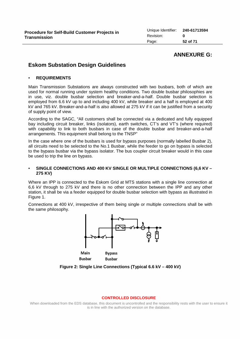
Procedure for Self-Build Customer Projects in Transmission
CONTROLLED DISCLOSURE When downloaded from the EDS database, this document is uncontrolled and the responsibility rests with the user to ensure it
is in line with the authorized version on the database.
Unique Identifier: 240-61713594 Revision: 0 Page: 52 of 71
ANNEXURE G:
Eskom Substation Design Guidelines
• REQUIREMENTS
Main Transmission Substations are always constructed with two busbars, both of which are used for normal running under system healthy conditions. Two double busbar philosophies are in use, viz. double busbar selection and breaker-and-a-half. Double busbar selection is employed from 6.6 kV up to and including 400 kV, while breaker and a half is employed at 400 kV and 765 kV. Breaker-and-a-half is also allowed at 275 kV if it can be justified from a security of supply point of view.
According to the SAGC, “All customers shall be connected via a dedicated and fully equipped bay including circuit breaker, links (isolators), earth switches, CT’s and VT’s (where required) with capability to link to both busbars in case of the double busbar and breaker-and-a-half arrangements. This equipment shall belong to the TNSP”
In the case where one of the busbars is used for bypass purposes (normally labelled Busbar 2), all circuits need to be selected to the No.1 Busbar, while the feeder to go on bypass is selected to the bypass busbar via the bypass isolator. The bus coupler circuit breaker would in this case be used to trip the line on bypass.
• SINGLE CONNECTIONS AND 400 KV SINGLE OR MULTIPLE CO NNECTIONS (6,6 KV – 275 KV)
Where an IPP is connected to the Eskom Grid at MTS stations with a single line connection at 6,6 kV through to 275 kV and there is no other connection between the IPP and any other station, it shall be via a feeder equipped for double busbar selection with bypass as illustrated in Figure 1.
Connections at 400 kV, irrespective of them being single or multiple connections shall be with the same philosophy.
Figure 2: Single Line Connections (Typical 6.6 kV – 400 kV)
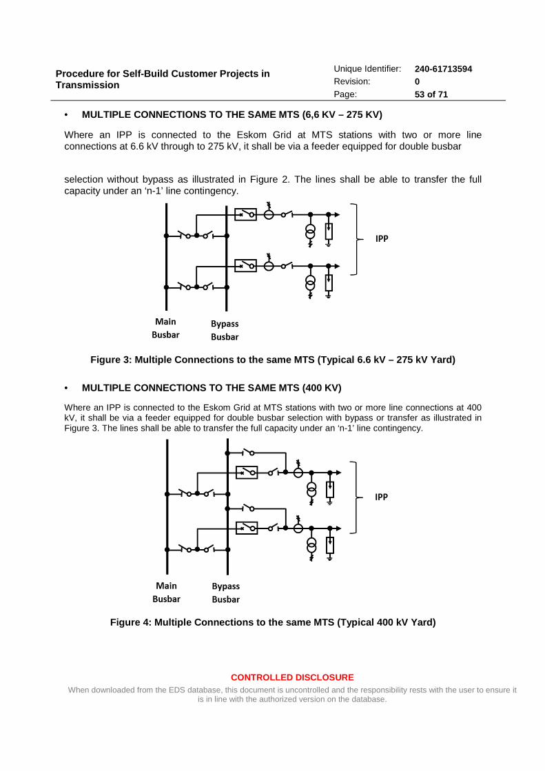
Procedure for Self-Build Customer Projects in Transmission
CONTROLLED DISCLOSURE When downloaded from the EDS database, this document is uncontrolled and the responsibility rests with the user to ensure it
is in line with the authorized version on the database.
Unique Identifier: 240-61713594 Revision: 0 Page: 53 of 71
• MULTIPLE CONNECTIONS TO THE SAME MTS (6,6 KV – 275 KV)
Where an IPP is connected to the Eskom Grid at MTS stations with two or more line connections at 6.6 kV through to 275 kV, it shall be via a feeder equipped for double busbar
selection without bypass as illustrated in Figure 2. The lines shall be able to transfer the full capacity under an ‘n-1’ line contingency.
Figure 3: Multiple Connections to the same MTS (Typ ical 6.6 kV – 275 kV Yard)
• MULTIPLE CONNECTIONS TO THE SAME MTS (400 KV)
Where an IPP is connected to the Eskom Grid at MTS stations with two or more line connections at 400 kV, it shall be via a feeder equipped for double busbar selection with bypass or transfer as illustrated in Figure 3. The lines shall be able to transfer the full capacity under an ‘n-1’ line contingency.
Figure 4: Multiple Connections to the same MTS (Typ ical 400 kV Yard)

Procedure for Self-Build Customer Projects in Transmission
CONTROLLED DISCLOSURE When downloaded from the EDS database, this document is uncontrolled and the responsibility rests with the user to ensure it
is in line with the authorized version on the database.
Unique Identifier: 240-61713594 Revision: 0 Page: 54 of 71
• SINGLE CONNECTIONS TO DIFFERENT MTSS (6,6 KV – 275 KV)
Where an IPP is connected to the Eskom Grid at two different MTS stations with one line into each station, connections being at 6,6 kV through to 275 kV, it shall be via a feeder equipped for double busbar selection without bypass as illustrated in Figure 4. Each of the lines shall be able to transfer the full capacity under an ‘n-1’ line contingency.
Figure 5: Single Connections to Different MTSs (Typ ical 6.6 kV – 275 kV Yard)
• SINGLE CONNECTIONS TO DIFFERENT MTSS (400 KV)
Where an IPP is connected to the Eskom Grid at MTS stations with two or more line connections at 400 kV, it shall be via a feeder equipped for double busbar selection with bypass or transfer as illustrated in Figure 5. The lines shall be able to transfer the full capacity under an ‘n-1’ line contingency.

Procedure for Self-Build Customer Projects in Transmission
CONTROLLED DISCLOSURE When downloaded from the EDS database, this document is uncontrolled and the responsibility rests with the user to ensure it
is in line with the authorized version on the database.
Unique Identifier: 240-61713594 Revision: 0 Page: 55 of 71
Figure 6: Single Connections to Different MTSs (Typ ical 400 kV Yard)
• SINGLE CONNECTION TO MTS WITH SINGLE CONNECTION TO A DISTRIBUTION SUBSTATION (6,6 KV – 132 KV)
Where an IPP is connected to the Eskom Grid at a MTS station and a Distribution, each with a single line, and the MTS and Distribution stations are also interconnected creating a three way tie, providing any of the line routes are able to transfer the full load, the connections shall be via a feeder equipped for double busbar selection without bypass as illustrated in Figure 3. The lines shall be able to transfer the full capacity under an ‘n-1’ line contingency.
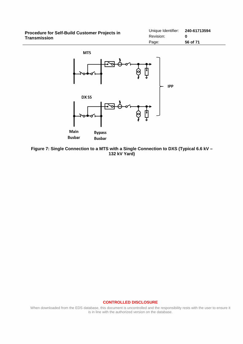
Procedure for Self-Build Customer Projects in Transmission
CONTROLLED DISCLOSURE When downloaded from the EDS database, this document is uncontrolled and the responsibility rests with the user to ensure it
is in line with the authorized version on the database.
Unique Identifier: 240-61713594 Revision: 0 Page: 56 of 71
Figure 7: Single Connection to a MTS with a Single Connection to DXS (Typical 6.6 kV – 132 kV Yard)

Procedure for Self-Build Customer Projects in Transmission
CONTROLLED DISCLOSURE When downloaded from the EDS database, this document is uncontrolled and the responsibility rests with the user to ensure it
is in line with the authorized version on the database.
Unique Identifier: 240-61713594 Revision: 0 Page: 57 of 71
• SINGLE OR MULTIPLE CONNECTIONS TO MTS BUILT WITH TH E BREAKER-AND-A-HALF PHILOSOPHY (6,6 KV – 800 KV)
Where an IPP is connected to the Eskom Grid at a MTS station via either a single or multiple line and the busbar system of the connecting voltage is breaker-and-a-half, the connection shall be done with a breaker-and-a-half arrangement as illustrated in Figures 7 and 8.
Figure 8: Single Breaker-and-Half Connection (Typic al 6.6 kV – 800 kV Yard)
Figure 9: Multiple Breaker-and-Half Connection (Typ ical 6.6 kV – 800 kV Yard)
Procedure for Self-Build Customer Projects in Transmission
CONTROLLED DISCLOSURE When downloaded from the EDS database, this document is uncontrolled and the responsibility rests with the user to ensure it
is in line with the authorized version on the database.
Unique Identifier: 240-61713594 Revision: 0 Page: 58 of 71
ANNEXURE H:
TX SELF-BUILD CONNECTION AGREEMENT PRO-FORMA
(To be supplied by the Eskom Project Manager)
Procedure for Self-Build Customer Projects in Transmission
CONTROLLED DISCLOSURE When downloaded from the EDS database, this document is uncontrolled and the responsibility rests with the user to ensure it
is in line with the authorized version on the database.
Unique Identifier: 240-61713594 Revision: 0 Page: 59 of 71
ANNEXURE I:
TYPICAL ESKOM STANDARD EQUIPMENT RATINGS
Eskom has adopted a set of standard equipment ratings to be used in all new and refurbishment works. The set of equipment ratings has been selected with due regard to present and future customer and system requirements, as well as applicable international design standards, and is reviewed periodically as required. The purpose of standardisation is to minimise spares holding requirements, whilst ensuring that adequate spares are available for routine maintenance and repair or replacement of equipment that fails in service.
In the case of switchgear, instrument transformers, line traps, post and longrod insulators, and other HV equipment manufactured to suppliers’ standard designs, standard ratings are driven by international design standards (IEC, DIN, British Standard, ANSI, etc.) which are produced and reviewed periodically by panels of industry experts drawn from manufacturers and users.
Eskom places national contracts for the supply of equipment that is used on a regular basis (e.g. switchgear) for a fixed period, to minimise lead times and costs. It is advisable for customers or their consultants to contact the Eskom project manager regarding the latest range of standard equipment and suppliers’ details.
In the case of transformers, electric utilities around the world have evolved their own sets of size standards to meet their respective requirements. In Eskom’s case, the set of standard transformer sizes currently in use was driven by a need to minimise the range of types of transformers to minimise the strategic spares holding requirements to ensure timeous replacement of failed or failing units, whilst ensuring that customer needs are met as cost effectively as practicable. Other factors influencing the choice included standard tap changer ratings, switchgear ratings, and transportability.
It is therefore possible that the best fit standard transformer rating to meet the Customer’s needs may appear to be excessive at first glance, but the use of the standard transformer will minimise turnaround time in the event of it failing in service. For example, if a standard 250MVA 275/132kV transformer is used to connect a customer who requires a 150MVA connection at 132kV, then it can be replaced with a 250MVA 275/132kV transformer drawn from Eskom’s strategic spares stock if it fails in service. This can be done in weeks, provided that the failure did not result in damage to other equipment or facilities through fire or explosion. However, if a non-standard transformer (e.g. 150MVA 275/132kV) is used, then either a replacement non-standard unit will have to be ordered (lead time up to 36 months, depending on global demand and available spare capacity at factories), or modifications done to enable a standard size replacement to be installed (lead time several months, or longer if other equipment also needs replacing e.g. due to higher fault levels).
There is a legacy of non-standard transformers that were installed before standardisation of transformer ratings came into effect. Many of these have already been replaced after failing in service, or being identified by condition monitoring as having reached end of life and hence at risk of imminent failure. The remaining non-standard transformers at transmission voltages are over 40 years old and nearing end of life, and most have been earmarked for replacement with the most appropriate standard units to meet present and future customer needs.
The current set of standard transformer sixes is as follows:
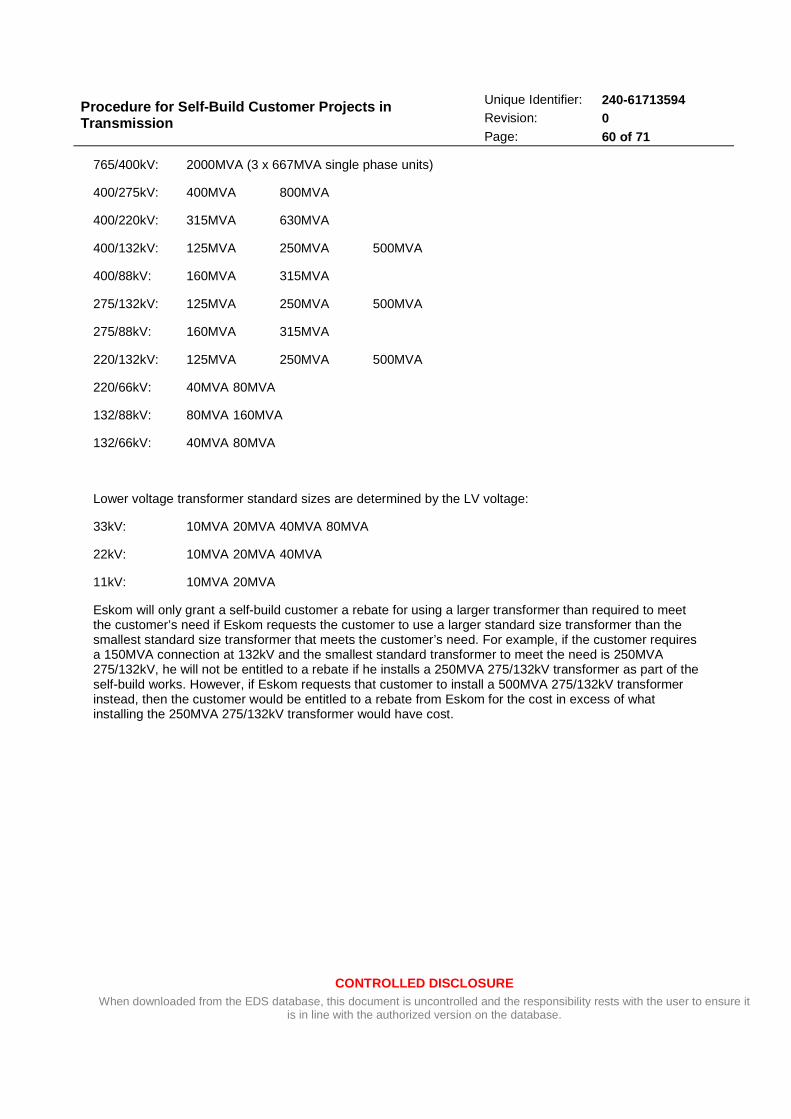
Procedure for Self-Build Customer Projects in Transmission
CONTROLLED DISCLOSURE When downloaded from the EDS database, this document is uncontrolled and the responsibility rests with the user to ensure it
is in line with the authorized version on the database.
Unique Identifier: 240-61713594 Revision: 0 Page: 60 of 71
765/400kV: 2000MVA (3 x 667MVA single phase units)
400/275kV: 400MVA 800MVA
400/220kV: 315MVA 630MVA
400/132kV: 125MVA 250MVA 500MVA
400/88kV: 160MVA 315MVA
275/132kV: 125MVA 250MVA 500MVA
275/88kV: 160MVA 315MVA
220/132kV: 125MVA 250MVA 500MVA
220/66kV: 40MVA 80MVA
132/88kV: 80MVA 160MVA
132/66kV: 40MVA 80MVA
Lower voltage transformer standard sizes are determined by the LV voltage:
33kV: 10MVA 20MVA 40MVA 80MVA
22kV: 10MVA 20MVA 40MVA
11kV: 10MVA 20MVA
Eskom will only grant a self-build customer a rebate for using a larger transformer than required to meet the customer’s need if Eskom requests the customer to use a larger standard size transformer than the smallest standard size transformer that meets the customer’s need. For example, if the customer requires a 150MVA connection at 132kV and the smallest standard transformer to meet the need is 250MVA 275/132kV, he will not be entitled to a rebate if he installs a 250MVA 275/132kV transformer as part of the self-build works. However, if Eskom requests that customer to install a 500MVA 275/132kV transformer instead, then the customer would be entitled to a rebate from Eskom for the cost in excess of what installing the 250MVA 275/132kV transformer would have cost.
Procedure for Self-Build Customer Projects in Transmission
CONTROLLED DISCLOSURE When downloaded from the EDS database, this document is uncontrolled and the responsibility rests with the user to ensure it
is in line with the authorized version on the database.
Unique Identifier: 240-61713594 Revision: 0 Page: 61 of 71
ANNEXURE J:
THE ESKOM ASSET CLASSES AND THE GUIDELINE ON COST-ALLOCATION
To facilitate the transfer of the self-build assets to Eskom’s asset register, the Transmission Division’s asset classes and cost-allocation guidelines must be adhered to.

Procedure for Self-Build Customer Projects in Transmission
CONTROLLED DISCLOSURE When downloaded from the EDS database, this document is uncontrolled and the responsibility rests with the user to ensure it
is in line with the authorized version on the database.
Unique Identifier: 240-61713594 Revision: 0 Page: 62 of 71
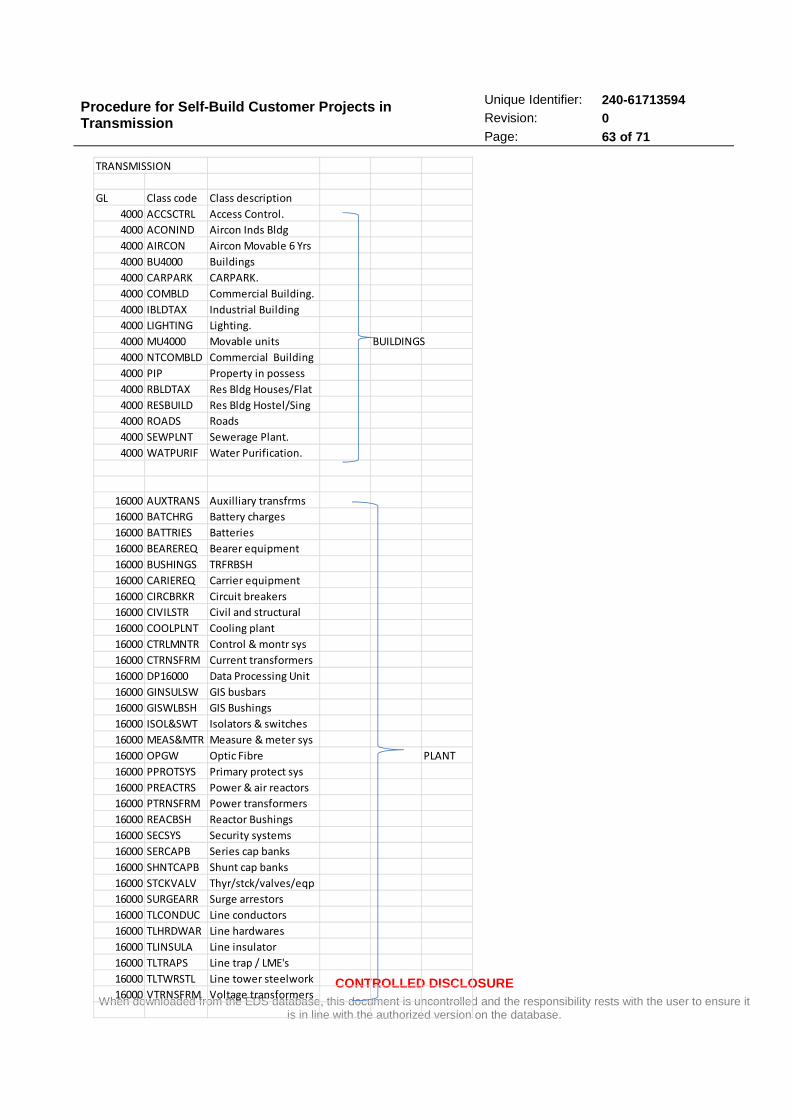
Procedure for Self-Build Customer Projects in Transmission
CONTROLLED DISCLOSURE When downloaded from the EDS database, this document is uncontrolled and the responsibility rests with the user to ensure it
is in line with the authorized version on the database.
Unique Identifier: 240-61713594 Revision: 0 Page: 63 of 71
TRANSMISSION
GL Class code Class description
4000 ACCSCTRL Access Control.
4000 ACONIND Aircon Inds Bldg
4000 AIRCON Aircon Movable 6 Yrs
4000 BU4000 Buildings
4000 CARPARK CARPARK.
4000 COMBLD Commercial Building.
4000 IBLDTAX Industrial Building
4000 LIGHTING Lighting.
4000 MU4000 Movable units BUILDINGS
4000 NTCOMBLD Commercial Building
4000 PIP Property in possess
4000 RBLDTAX Res Bldg Houses/Flat
4000 RESBUILD Res Bldg Hostel/Sing
4000 ROADS Roads
4000 SEWPLNT Sewerage Plant.
4000 WATPURIF Water Purification.
16000 AUXTRANS Auxilliary transfrms
16000 BATCHRG Battery charges
16000 BATTRIES Batteries
16000 BEAREREQ Bearer equipment
16000 BUSHINGS TRFRBSH
16000 CARIEREQ Carrier equipment
16000 CIRCBRKR Circuit breakers
16000 CIVILSTR Civil and structural
16000 COOLPLNT Cooling plant
16000 CTRLMNTR Control & montr sys
16000 CTRNSFRM Current transformers
16000 DP16000 Data Processing Unit
16000 GINSULSW GIS busbars
16000 GISWLBSH GIS Bushings
16000 ISOL&SWT Isolators & switches
16000 MEAS&MTR Measure & meter sys
16000 OPGW Optic Fibre PLANT
16000 PPROTSYS Primary protect sys
16000 PREACTRS Power & air reactors
16000 PTRNSFRM Power transformers
16000 REACBSH Reactor Bushings
16000 SECSYS Security systems
16000 SERCAPB Series cap banks
16000 SHNTCAPB Shunt cap banks
16000 STCKVALV Thyr/stck/valves/eqp
16000 SURGEARR Surge arrestors
16000 TLCONDUC Line conductors
16000 TLHRDWAR Line hardwares
16000 TLINSULA Line insulator
16000 TLTRAPS Line trap / LME's
16000 TLTWRSTL Line tower steelwork
16000 VTRNSFRM Voltage transformers
Procedure for Self-Build Customer Projects in Transmission
CONTROLLED DISCLOSURE When downloaded from the EDS database, this document is uncontrolled and the responsibility rests with the user to ensure it
is in line with the authorized version on the database.
Unique Identifier: 240-61713594 Revision: 0 Page: 64 of 71
ANNEXURE K:
Eskom Line Design Requirements
a) The self-build customer will be responsible for the appointment of Eskom approved line design
consultants as per Annexure E. An updated list of Eskom approved panel contractors will be
available from the Eskom Line Engineering Services Department (LES).
b) The customer will follow a line design process as indicated in the Lines Engineering Business
Process (LEBP) depicted in Figures H1 and H2.
c) All input information required to follow the Business Process will be the customers’
responsibility.
d) The customer will conduct concept and detail line designs in accordance with Eskom’s design
standards, practices and specifications. Strict compliance to the SABS 0280 for design practices
will be maintained.
e) Eskom standards and specifications for line components as well as design templates will be
provided to the customer.
f) Prior to the CRA phase, the customer shall arrange a kick-off meeting with the Lines Design
Review Team (Lines DRT) where a presentation will be made to introduce the project and its
motivation, indicate the proposed method of approach and alignment to the LEBP, highlight key
design parameters and define critical dates including those related to LEBP hold points.
g) No line design proposal will be accepted by LES until all the network planning issues had been
concluded with written sign offs by the Eskom Planning Department.
h) Any design standard, practice, specification and standardised design issued to the self-build
customer shall be used solely for the purpose for which they were issued and that Eskom
copyright shall be adhered to at all times.
i) The self-build customer shall be responsible for purchasing applicable third party design
standards, specifications and software (e.g. PLSCAD).
j) Each design stage; CRA (Concept Design), DRA (Detail Design) and ERA (Construction and Tender
Documents), will be presented by the customer to the Lines DRT.

Procedure for Self-Build Customer Projects in Transmission
CONTROLLED DISCLOSURE When downloaded from the EDS database, this document is uncontrolled and the responsibility rests with the user to ensure it
is in line with the authorized version on the database.
Unique Identifier: 240-61713594 Revision: 0 Page: 65 of 71
k) Each design stage must be reviewed and accepted by the Lines DRT prior to commencement of
the next stage.
l) The onus is on the customer to arrange their attendance to and provide all necessary design
documentation to the secretariat of the Lines DRT at least two weeks prior to any scheduled
meeting.
m) Eskom LES must be consulted on the format and template of the design submission of each
stage.
n) The customer and the appointed contractor must adhere to the construction guidelines as
stated in the latest revision of TRMSCAAC1 “The Design and Construction of Overhead Power
Lines”.
Eskom Line Engineering Business Process
a) At CRA process initiation, line engineering activities commences once the most probable power
corridor of 3 options has been identified. A flyover or walk down is conducted to ascertain route
suitability from a technical viewpoint. Findings are presented at the design kick-off meeting for
the project. This process has to be formalised for the self-build projects.
b) From the planning requirements, the most suitable conductor and tower options are identified
from a range of options available. In some cases, tower options may not exist and will have to
be developed from scratch. Selecting the appropriate conductor for the anticipated load
forecast is the result of comprehensive engineering technical and economic studies. Results and
justification of options are captured in a Preliminary Design Report which is then presented,
reviewed and accepted at Lines DRT level.
c) Once the Preliminary Design Report has been revised, if necessary, and accepted by the DRT, the
selection of all other line components commence. Depending on the environmental sensitivity,
site pollution monitoring can be initiated quite early since at least two years of pollution data is
required to make a fair assessment for insulator requirements. The customer can also check
with LES if pollution data is available for any proposed servitude. The selection of line
components and justification of options is captured in a Detailed Design Report, which must also
be presented, evaluated and accepted by the Lines DRT.
d) Preliminary profiles are prepared at the detailed design stage and must be submitted to LES for
review and acceptance.
e) Templates for the Preliminary and Detailed Design Reports can be obtained from LES upon
request.

Procedure for Self-Build Customer Projects in Transmission
CONTROLLED DISCLOSURE When downloaded from the EDS database, this document is uncontrolled and the responsibility rests with the user to ensure it
is in line with the authorized version on the database.
Unique Identifier: 240-61713594 Revision: 0 Page: 66 of 71
f) Acceptance of the Detailed Design Report concludes the CRA phase.
g) The DRA phase is initiated with the preparation of specifications for all line components. All
suppliers and materials used on Eskom lines have undergone extensive evaluation and
acceptance. The customer must indicate the use of non-accepted materials for consideration by
LES. The preference will be for pre-approved materials and suppliers.
h) Final profiles are compiled during the DRA phase.
i) All line specifications and profiles must be signed off by LES.
j) A squad check meeting must be held to identify and further risks to the project preparation
prior to tender issue. These risks must be resolved prior to any tender issue or contractor
nomination by the customer.
k) Following contract award, the contractor must be briefed on required processes, documentation
and safety as specified in TRMSCAAC1.
l) LES will conduct audits during line construction as and when necessary.

Procedure for Self-Build Customer Projects in Transmission
CONTROLLED DISCLOSURE When downloaded from the EDS database, this document is uncontrolled and the responsibility rests with the user to ensure it
is in line with the authorized version on the database.
Unique Identifier: 240-61713594 Revision: 0 Page: 67 of 71
Figure H1. Line Engineering Business Process: CRA Phase

Procedure for Self-Build Customer Projects in Transmission
CONTROLLED DISCLOSURE When downloaded from the EDS database, this document is uncontrolled and the responsibility rests with the user to ensure it
is in line with the authorized version on the database.
Unique Identifier: 240-61713594 Revision: 0 Page: 68 of 71
Figure H2. Line Engineering Business Process: DRA Phase
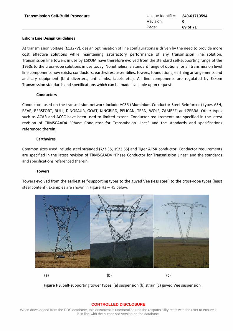
Transmission Self-Build Procedure
CONTROLLED DISCLOSURE When downloaded from the EDS database, this document is uncontrolled and the responsibility rests with the user to ensure it
is in line with the authorized version on the database.
Unique Identifier: 240-61713594 Revision: 0 Page: 69 of 71
Eskom Line Design Guidelines
At transmission voltage (≥132kV), design optimisation of line configurations is driven by the need to provide more
cost effective solutions while maintaining satisfactory performance of any transmission line solution.
Transmission line towers in use by ESKOM have therefore evolved from the standard self-supporting range of the
1950s to the cross-rope solutions in use today. Nonetheless, a standard range of options for all transmission level
line components now exists; conductors, earthwires, assemblies, towers, foundations, earthing arrangements and
ancillary equipment (bird diverters, anti-climbs, labels etc.). All line components are regulated by Eskom
Transmission standards and specifications which can be made available upon request.
Conductors
Conductors used on the transmission network include ACSR (Aluminium Conductor Steel Reinforced) types ASH,
BEAR, BERSFORT, BULL, DINOSAUR, GOAT, KINGBIRD, PELICAN, TERN, WOLF, ZAMBEZI and ZEBRA. Other types
such as ACAR and ACCC have been used to limited extent. Conductor requirements are specified in the latest
revision of TRMSCAAD4 “Phase Conductor for Transmission Lines” and the standards and specifications
referenced therein.
Earthwires
Common sizes used include steel stranded (7/3.35, 19/2.65) and Tiger ACSR conductor. Conductor requirements
are specified in the latest revision of TRMSCAAD4 “Phase Conductor for Transmission Lines” and the standards
and specifications referenced therein.
Towers
Towers evolved from the earliest self-supporting types to the guyed Vee (less steel) to the cross-rope types (least
steel content). Examples are shown in Figure H3 – H5 below.
(a) (b) (c)
Figure H3. Self-supporting tower types: (a) suspension (b) strain (c) guyed Vee suspension
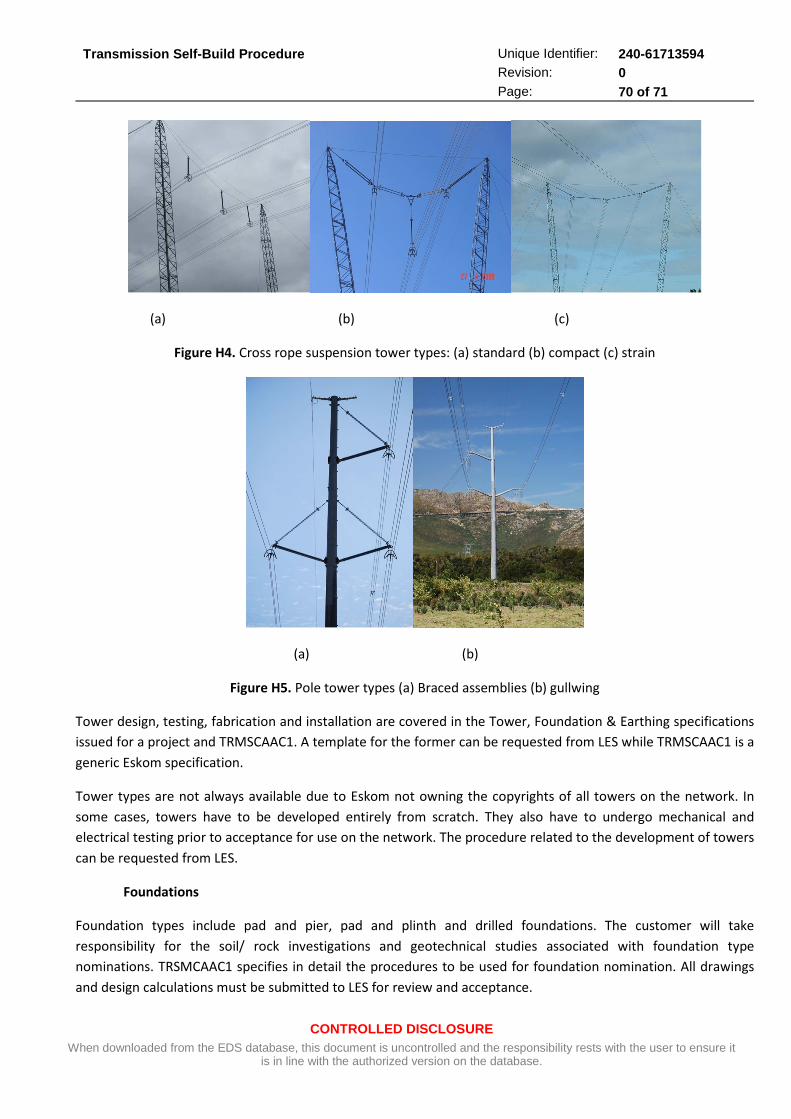
Transmission Self-Build Procedure
CONTROLLED DISCLOSURE When downloaded from the EDS database, this document is uncontrolled and the responsibility rests with the user to ensure it
is in line with the authorized version on the database.
Unique Identifier: 240-61713594 Revision: 0 Page: 70 of 71
(a) (b) (c)
Figure H4. Cross rope suspension tower types: (a) standard (b) compact (c) strain
(a) (b)
Figure H5. Pole tower types (a) Braced assemblies (b) gullwing
Tower design, testing, fabrication and installation are covered in the Tower, Foundation & Earthing specifications
issued for a project and TRMSCAAC1. A template for the former can be requested from LES while TRMSCAAC1 is a
generic Eskom specification.
Tower types are not always available due to Eskom not owning the copyrights of all towers on the network. In
some cases, towers have to be developed entirely from scratch. They also have to undergo mechanical and
electrical testing prior to acceptance for use on the network. The procedure related to the development of towers
can be requested from LES.
Foundations
Foundation types include pad and pier, pad and plinth and drilled foundations. The customer will take
responsibility for the soil/ rock investigations and geotechnical studies associated with foundation type
nominations. TRSMCAAC1 specifies in detail the procedures to be used for foundation nomination. All drawings
and design calculations must be submitted to LES for review and acceptance.
Transmission Self-Build Procedure
CONTROLLED DISCLOSURE When downloaded from the EDS database, this document is uncontrolled and the responsibility rests with the user to ensure it
is in line with the authorized version on the database.
Unique Identifier: 240-61713594 Revision: 0 Page: 71 of 71
Assemblies
Insulators and hardware used on transmission lines have been pre-approved on the Eskom system. Insulators
include the use of glass cap and pin and silicone rubber types. Various standard hardware configurations exist at
each voltage level and conceptual drawings can be obtained from LES as required.
Eskom’s TSP41-452 and TRMSCABS9 are the applicable standards related to glass and composite (silicone)
insulators respectively. TRMSCAAH2 govern the use of suspension and strain hardware components.
OPGW
As necessary, transmission lines can require Optical Ground Wire (OPGW) to be fitted. OPGW forms an important
component of the modern telecommunications and protection systems. This is additional to the normal role of
the standard steel earthwire for lightning protection and fault current dissipation. OPGW use is governed by the
national NRS 061 standard and related standards.
LES can provide templates for specifications related to all line components above as necessary.