pro guide 2013 - aljoma lumber · pro guide 2013 latitudesdeck.com. ... each rail kit contains (2)...
TRANSCRIPT

The right way to go™
Pro Guide 2013LatitudesDeck.com

3 Latitudes Capricorn Decking
4 Latitudes Captiva Decking
5 Latitudes Intrepid Decking
6 Latitudes Wave Decking
7 Latitudes Marine Decking
8 Latitudes Intrepid Composite Railing
9 Latitudes Intrepid Composite Railing With Ornamental Balusters
Contents
Latitudes Wave decking in walnut with smoke slate deck stones
10 Secondary Handrail
12 Latitudes Accessories
14 Fascia and Decorative Fascia Corners
15 Color Variation and Fading
16 Frequently Asked Questions
20 Decking Installation
24 Railing Installation
34 Secondary Handrail Guidelines and Installation
36 Recessed Lighting Kit Installation
37 Deck Stones Installation
38 Warranty Information
44 ICC-ES Evaluation Report
46 MSDS Report

Inspired by some of the most beautiful timbers from the farthest
points of the globe, and capped with technology that stands the
test of time, this award-winning composite decking takes nature
up a notch. With Latitudes Capricorn Decking, your backyard
will be the talk of the town and the envy of the neighborhood.
You’ll have to look very closely to see that Latitudes Capricorn isn’t
real tropical hardwood. It’s constructed from our special blend of wood
fiber and plastics and capped with some of the most durable polymer
Latitudes Capricorn® Decking
technology available. That means it can withstand heavy traffic, take
a beating from Mother Nature, and still retain its exotic beauty.
Latitudes Capricorn delivers exceptional resistance to fading,
water damage, staining and scratching, leaving you with a
smooth, beautiful deck surface, season after season.
Contour and solid profiles available
3
KoaArabica
Capricorn koa decking
LatitudesProfiles.ai
LatitudesProfiles.ai

4
Latitudes® Captiva decking offers many of the finer aesthetic and
performance qualities of Capricorn—at a temptingly lower price.
Like Capricorn, Captiva is capped with a rugged polymer technology that
allows it to be stain and fade resistant. Its natural-looking walnut, cedar,
gray and willow colors and woodgrain finish make Captiva the perfect blend
of beauty and performance. It will withstand years of heavy use and harsh
weather to give you remarkably lasting beauty with the least amount of care.
Captivating looks. Easy, long-lasting performance at a
surprisingly moderate price. You can see why Latitudes
Captiva captures buyers’ attention and refuses to let go.
Slotted-edge profile boardsLatitudes Capricorn and Captiva slotted-edge decking is
designed for use with our Equator hidden fastener and is
encapsulated on one side. Solid-edge decking is also available,
perfect for use on stairs and as a perimeter board.
Latitudes Captiva™ Decking
Cap stock
This new generation of Latitudes Captiva is capped with the most durable polymer technology available to withstand the ravages of weather, time and use. With this new cap stock technology, your deck will look gorgeous, resist scratching, and be remarkably easy to clean. Beautiful and virtually maintenance-free. It’s the right way to go.
Captiva willow decking
Gray Cedar Walnut Willow
Contour and solid profiles available
LatitudesProfiles.ai
LatitudesProfiles.ai

Latitudes Intrepid™ decking features the natural look and workability of wood and is a perfect low-maintenance alternative. Offered in four natural colors and in 12-, 16- and 20-foot lengths, each compos-ite board is splinter-free, barefoot-friendly, slip-resistant and revers-ible, with a woodgrain pattern on one side and a brushed finish on the other. Intrepid boards come in a solid profile or slotted for use with our Equator® hidden fastener system.
And because Latitudes Intrepid decking uses Strandex® inside, you can be assured you’re getting the highest quality and strongest composite product available. With its proven track record for durability and resistance to water absorption, Strandex enjoys widespread contractor acceptance.
Latitudes Intrepid decking provides classic styling, enduring beauty and carefree performance, year after year. And we back our quality with a 25-year limited structural warranty.
Latitudes Intrepid™ Decking
Walnut decking woodgrain
Redwood decking brushed
Cedar decking brushed
Walnut decking brushed
Reversible Finish
Cedar decking woodgrain
Redwood decking woodgrain
Gray decking woodgrain
Gray decking brushed
LatitudesProfiles.ai
LatitudesProfiles.ai
5
The Equator® hidden fastener system secures deck boards on their sides using our exclusive gap-wing clips (shown here) that attach to joists with a single stainless steel, color-matched screw. This system results in a beautiful, smooth and virtually fastener-free decking surface, while greatly speeding installation by auto-matically spacing boards at the proper intervals and eliminating the need for pre-drilling.
Slotted and solid profiles available

6
Latitudes Wave decking features the classic look and reliability of Latitudes at a more affordable price. The decking offers the same Strandex® technology and is extruded with the same contour profile as our capped decking. Offered in gray and walnut, it's backed by a 25-year limited warranty.
Use the Latitudes Intrepid railing and baluster options to give your deck the look you prefer. By pairing the low maintenance and performance of Strandex with a rich woodgrain pattern, Latitudes Wave is the right way to go.
Latitudes Wave™ Decking
Gray Walnut
Latitudes Wave walnut decking with cedar Latitudes Intrepid 2x4 railing and black arch aluminum balusters6
LatitudesProfiles.ai
LatitudesProfiles.ai
Slotted and solid profiles available

Latitudes Marine decking dimensions
1-1⁄4"
5-7⁄16" +/- 1⁄32"
(Sizes shown are actual)
Latitudes Marine gray decking
Latitudes® Marine composite decking is designed for use in heavy traffic or in wet environments such as marinas, boardwalks and docks. Latitudes Marine is thicker than typical composite deck boards and is engineered for use on wide joist spacing. Latitudes Marine decking dimensions are 1-1/4" x 5-7/16" x 16', with a durable appearance designed for marina applications where a maximum of 24" on-center joist spacing is needed.
Latitudes Marine Decking
Latitudes Marine decking is fortified with the same proven Strandex® technology used in all Latitudes composite products. The proven Strandex process—combined with an optimal balance of wood fiber and polymers—ensures superior protection against UV degr adation and water absorption. What’s more, Latitudes Marine decking is covered with a 10-year commercial limited warranty and a 25-year residential limited warranty.
7
Gray Redwood Cedar Walnut

8
Latitudes Intrepid™ Composite RailingLatitudes Intrepid™ composite railing is the perfect complement to Latitudes Intrepid or Wave decking and is available in four matching colors: cedar, redwood, walnut and gray. Intrepid railing features a robust, symmetrical railing profile with an innovative hidden fastener
system. The concealed mounting hardware allows for fast, easy installation and provides a clean, seamless appearance. The pre-drilled insert rail ensures proper spacing and ease of assembly.
6' Latitudes Intrepid Line Rail Kit• Kitincludes:(1)toprail,(1)pre-drilled
lower rail, (2) predrilled insert rails
•Includesallbracketsandhardware for one 6' on-center railing
52" Post Sleeve Kit• 4-9 ⁄16" x 4-9 ⁄16" (+/-1 ⁄32") — 52"
• Designedtofitoveratreated, nominal 4x4 post
• Includespostbasetrim
Intrepid railing is code-compliant* and does not need any sup-port inserts. Intrepid railing and ornamental balusters are packed in boxed kits for a standard 6-foot on-center section. Choose from square composite, round aluminum or square aluminum baluster kits. Matching two-piece post base trim rings come standard with all post sleeve kits.
* Consult local building codes to ensure code compliance.
Angle Bracket Kit• Includesfourbracketswithhardware
• Adjustablefor22.5°and45°railangles
Composite Baluster Kit• Includes15compositebalusters
with stainless steel, powder-coated, color-matched screws
• 1-1⁄4" x 1-1⁄4" — 38"
Round Baluster Kit•Includes15balustersperkit
•3⁄4" x 32" or 3⁄4" x 36"
•Powder-coatedaluminumin bronze, black, white or stainless
•Usewithincluded FastBallTM connectors
Square Baluster Kit• Includes15balustersand
30 square baluster connectors
• 3⁄4" x 32"
• Powder-coatedaluminum in bronze or black
Square Baluster Stair Adaptors• Combinewithsquare
baluster connectors
• Designedtofita35° stair angle
6' Latitudes Intrepid Stair Rail Kit• Kitincludes:(1)toprail,(1)pre-drilled
lower rail, (2) predrilled insert rails
•Includesallbracketsandhardware for one 6' on-center stair railing
The structural performance of the Latitudes Intrepid railing system has been evaluated through full-scale testing by Architectural Testing Inc (ATI). The results demonstrate that the different combinations of the railing system, as noted in ATI’s CCRR Report 0150, comply with the 2009 International Building Code; 2009 International Residential Code; ICC-ES AC174/June 1, 2009; ASTM D7032-07; and ANSI Z97.1-2004.
PFS AA-652 ASTM K7032 compliant. See ATI CCRR at www.ati-es.com for uses and performance levels.
Get the free mobile app at http://gettag.mobi
Scan code for tips on installing Latitudes Intrepid composite railing.

Latitudes Intrepid™ 2x4 railing kit features a railing that connects to the Intrepid-style top rail profile. This 6-foot code-compliant* railing system allows for simple installations of all Latitudes face-mount baluster kits. Transparent glass balusters provide an attractive yet durable option. Made of 5⁄16-
inch thick tempered safety glass, this unique baluster is as strong
2x4-6' Latitudes Intrepid Line Rail Kit•Kitincludes:(2)2x4rails,
(4) black 2x4 rail connectors with hardware and (2) support blocks
Arch Baluster Kit• Includes14balusters
and color-matched screws
• 1"x32-1⁄4"
• Powder-coatedaluminum in bronze or black
as it is striking and allows for an unobstructed view. Heavy-gauge black and bronze-colored aluminum balusters are powder-coated and provide a wrought-iron appearance in three design options: arch, rectangular and contour. Each rail kit contains (2) Latitudes Intrepid 2x4-6' rails, (4) black rail connectors with hardware and (2) support blocks. Add a Latitudes Intrepid cap rail for a finished look.
* Consult local building codes to ensure code compliance.
Latitudes Intrepid™ Railing with Ornamental Balusters
Rectangular Baluster Kit• Includes14balusters
and color-matched screws
• 1"x32" (hollow profile)
• Powder-coatedaluminum in bronze or black
2x4 Angle Bracket Kit•Designed for 22.5°
and 45° rail angles
•Twoperpack
•Hardwareincluded
Round Balusters•Includes15balustersperkit
•3⁄4" x 32" or 3⁄4" x 36"
•Powder-coated,6063-T6 aluminum in bronze, black, white or stainless
•Usewithincluded FastBallTM connectors
Contour Baluster Kit• Includes14balusters
and color-matched screws
• 1"x32-1⁄4"
• Powder-coatedaluminum in bronze or black
Glass Baluster Kit• 4"x32"and29"
• 32"includesfiveclear glass balusters and stainless steel screws
•29"mustbemountedwith baluster connectors
• 5 ⁄16" tempered safety glass
Square Baluster Kit• Includes15balustersand
30 baluster connectors
• 3 ⁄4" x 32-1⁄4"
• Powder-coatedaluminum in bronze or black
Square Baluster Stair Adaptors• Combinewithsquare
baluster connectors
• Designedtofita35° stair angle
6' Latitudes IntrepidCap Rail Kit•Kitincludes:(1)caprail,
(1) insert rail and attachment hardware
•Forusewith2x4-6'railkit
2x4-6' Latitudes Intrepid Stair Rail Kit•Kitincludes:(2)2x4stair
rails, (2) black 2x4 stair rail connectors with hardware, (2) black 2x4 rail connectors with hardware and (2) support blocks
9
29" profile
32" profile

10
Graspable secondary handrails are required by building codes in areas across the country, especially in commercial applications. Latitudes includes a secondary handrail system that’s second to none: elegantly designed, durably constructed in aluminum andPVC,andversatileenoughtomeetevery
conceivable installation challenge and work with any Latitudes railing.
Available in four colors that complement popular siding and trim products used in new home and building construction, Latitudes secondary handrail is used in many different commercial and residential applications. It easily installs to your Latitudes railing product to create a functional and attractive secondary rail for stairways and locations where a graspable rail is required. Priorto construction, consult your local building code official for specific requirements in your area.
Secondary Handrail
8'8" Handrail with Aluminum Insert
1" Grab Rail End Cap 3" Offset Aluminum Bracket
3" Offset 90-Degree Aluminum Post Return
Straight Aluminum Wall Mount 1-3/4" Base
90-Degree Outside Corner
6" Inside Corner Mounting Bracket
90-Degree Inside Corner* 32-Degree Stair Elbow* 34-Degree Stair Elbow*
36-Degree Stair Elbow* 12" x 18" x 12" Handicap Loop*
180-Degree Post Return* 5-Degree Handicap Elbow* 13-1/2" Wall Return*
6" Aluminum Joiner Kit with Screws
5-3/4" Adjustable Joiner
Colors available: adobe, tan, white and black
* These items not available in black.

11
34-Degree Stair Elbow*
13-1/2" Wall Return*Design your dream deck online in minutes
with Latitudes Deck Visualizer.
LatitudesDeck.com/Visualizer
Get the free mobile app athttp://gettag.mobi
Scan code to learn more information aboutDeck Visualizer.

Solar Tiffany-Style Missionin walnut or redwood
12
Latitudes® Accessories
Customize your next deck project when you incorporate Latitudes® decorative accessories. Inspiring accessory options add a touch of pizzazz to any outdoor living area and make your Latitudes deck project the talk of the neighborhood.
Latitudes ornamental post caps enhance the beauty of your deck project and add the perfect finishing touch. Choose from colorful glass options, including solar-lit, and many more distinctive tops that elegantly complement Latitudes Decking and Railing.
Post CapsTop off your next deck project with Latitudes® ornamental post caps. Choose from a variety of styles that complement your home’s architecture, including colorful glass and distinctive metal tops.
Latitudes solar post caps allow you to light up your deck with-out wiring or electricity. The all-new solar Tiffany-style post caps are handmade works of art. By day, these post caps add the beauty of Tiffany-style stained glass to any outdoor area. By night, they enhance the deck with a soft welcoming glow.
Tiffany-Style Missionin walnut or redwood
Tiffany-Style Grapevinein gray
Tiffany-Style Sunflowerin cedar
CopperHighPointin cedar
StainlessHighPointin gray, redwood or walnut
Garnet Jewelin gray
Sapphire Jewelin gray
Solar Tiffany-Style Grapevinein gray
Solar Tiffany-Style Sunflowerin cedar
SolarPewteralso in white
Traditional Compositein gray, cedar, redwood or walnut
Give your customers a hint of beauty and added safety with Latitudes recessed lighting. These low-voltage, low-profile LED lights are a great way to accent steps, walkways and other deck features.
Latitudes™ deck stones lend creativity and a custom appearance to any deck project. Deck stones are a stylish add-on and a perfect alternative to composite decking when deck surface transitions are desired. Latitudes deck stones are ideal for use in outdoor kitchens, grill nooks and under raised fire pits.

Deck StonesLatitudes™ deck stones lend creativity and a custom appear-ance to any deck project. Deck stones are a stylish add-on and a perfect alternative to composite decking when deck surface transitions are desired. Latitudes deck stones are ideal for use in outdoor kitchens, grill nooks and under raised fire pits.
Smoke SlateRiverstone Granite
Get the free mobile app at http://gettag.mobi
Scan code to learn how to install deck stones.
Joist Connector
Recessed Lighting KitPerfectforsteplighting,Latitudes® recessed, low-voltage lighting kits provide a brilliant glow for walkways, directional lighting for steps or wherever better deck visibility is desired. Compact LED lights provide the perfect accent to decks, docks and patios with a clean, streamlined appearance. Each kit includes eight easy-to-install lights. Two-packs are also available to add to your existing project.
Get the free mobile app at http://gettag.mobi
Scan code to learn how to install recessed lighting.
13

14
Latitudes fascias are available in 1/2" x 9-1/4" - 12' and 1/2" x 11-1/4" - 12' size to match all Latitudes decking colors. Decorative fascia is used to conceal the decking understruc-ture; it is not intended for structural use. Made of the same Strandex® composition as Latitudes Decking and Railing, matching fascia colors eliminate the need to paint or stain the wood understructure. Fascia can also be used to wrap oversized posts.
1/2" x 11-1/4" x 12' fascia is available in all Latitudes decking colors
Ridge fascia corner
Leaf fascia corner
Fascia and Decorative Fascia Corners
Be the first in your circle to dress up your deck with our new decorative fascia corners. Simple and unique, decorative fascia corners provide a stylish way to adorn deck skirting and cover unsightly corner joints. Available in two designs—ridge and leaf—these black powder-coated corner design elements install easily with eight screws (supplied) and are available in three different heights: 7, 9 and 11 inches.
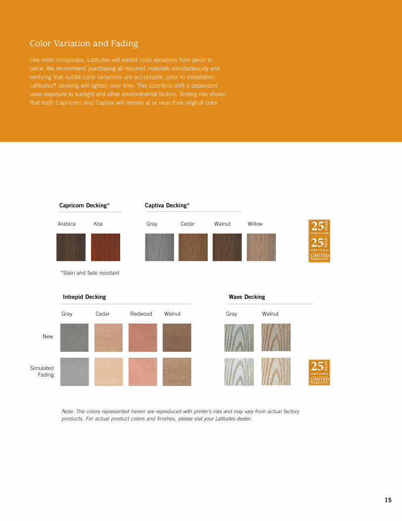
Note: The colors represented herein are reproduced with printer’s inks and may vary from actual factory products. For actual product colors and finishes, please visit your Latitudes dealer.
New
Arabica Koa Gray Cedar Walnut Willow
Capricorn Decking* Captiva Decking*
*Stain and fade resistant
Simulated Fading
Gray Cedar Redwood Walnut
Intrepid Decking
Color Variation and Fading
Like most composites, Latitudes will exhibit color variations from piece to piece. We recommend purchasing all required materials simultaneously and verifying that subtle color variations are acceptable, prior to installation. Latitudes® decking will lighten over time. This color-tone shift is dependent upon exposure to sunlight and other environmental factors. Testing has shown that both Capricorn and Captiva will remain at or near their original color.
15
Gray Walnut
Wave Decking

have black painted heads to reduce potential sunglare, keeping the fasteners truly hidden.
Because Latitudes Marine decking is thicker than other Latitudes deck boards, it is not available with a pre-machined groove.
Where can I buy Latitudes Decking and Railing? How much does it cost?The complete Latitudes line is available at retail lumberyards, home centers and through distributors. You can also visit www.latitudesdeck.com or call 877-463-8379. Latitudes decking is competitively priced in comparison to premium grades of wood decking and costs less than other high-end composite decking materials.
What is the difference between Latitudes composite decking and railing and wood?Latitudes Decking and Railing combines the look of wood with the durability of plastic. Unlike wood decks that require continuous maintenance, there is no need to apply weather protectants or water seal products to Latitudes Decking and Railing.
Why is composite decking more expensive than treated wood?Composite decking is more expensive to man-ufacture. Over time, however, maintenance, repair and/or replacement costs associated with wood outweigh the initial investment in Latitudes deck products.
What is the difference between Latitudes Intrepid moulded rail and 2x4 rail?The attractive Latitudes moulded rail can be installed with natural composite balusters, round aluminum balusters or square aluminum balusters. The 2x4 rail offers clean, straight lines and allows you to face mount ornamental arch, contour, rectangular and glass balusters. The natural composite balusters, round aluminum balusters and square aluminum balusters can also be used with the 2x4 rail.
Does Latitudes decking provide good traction in wet or dry conditions?Yes. Latitudes decking is slip-resistant.
Frequently Asked Questions
What are Latitudes® composite decking and railing made of?Latitudes composite decking and railing are made of wood and plastic that is extruded for strength. Latitudes Capricorn® tropical decking and Latitudes Captiva™, also made of wood and plastic, are co-extruded with a durable top layer for ultra low-maintenance performance. Both decking products are fortified with the same proven Strandex® technology used in all Latitudes composite products.
What colors and styles does Latitudes Decking and Railing come in?Latitudes Wave is available in gray and walnut with an embossed woodgrain finish. Latitudes Intrepid decking and Latitudes Marine deck-ing are available in gray, cedar, redwood and walnut, with a reversible finish: brushed on one side, embossed woodgrain on the other. Latitudes Capricorn decking is available in two rich colors, arabica and koa, which resemble the tropical hardwoods ipé and mahogany. Latitudes Captiva decking is available in gray, cedar, walnut and willow. We offer several different railing options to complement your decking project. Our matching Intrepid composite railing is available in gray, cedar, redwood and walnut colors in moulded and 2x4 profiles. We offer many styles of decorative balusters and post caps to provide a custom look.
What sizes and lengths does Latitudes Decking and Railing come in?Latitudes decking is available in 12-, 16- and 20-foot lengths. Additional components include a ½" x 9¼"-12' fascia board, ½" x 11¼"-12' fascia board, 52" post sleeve, 6-foot rail, 38-inch baluster, post cap and color-coordinating hardware kits with color-matched screws.
Latitudes Marine decking is thicker than typical composite deck boards and engineered for use on wide joist spacing. Latitudes Marine decking dimensions are 1¼" x 5 7/16" x 16'.
Should I purchase all of my decking material at one time?Yes.Purchasingallrequireddeckingmaterial at one time is recommended, as manufacturing runs can produce different colors. Like most composites, individual Latitudes deck boards will have color variations from piece to piece. This is due to the natural variations in wood fibers and polymers. Color variation is not covered by warranty. We recommend pur-chasing extra material in case boards need to be repaired or replaced in the future.
How do the railing kits work?Since we offer a wide selection of comple-mentary railing products, we package the components separately so you can choose the combination that best suits your taste. All components are sold in kits containing the appropriate materials to construct a 6-foot on-center railing. The only exception is the glass baluster kits sold in boxes of five for ease of shipment. Typically, two glass baluster kits are required per 6-foot on-center railing section.
What is the benefit of using solid composite decking instead of hollow composite decking?It is easier to work with a solid product because it frames like wood and feels more substantial on the deck.
What is the benefit of using Latitudes slotted decking instead of standard composite decking? Latitudes slotted decking comes with a pre- machined 5/32-inch groove along the sides of the board to accommodate the Equator® hidden fastener. The Equator hidden fasteners are designed to properly space the boards at ¼" and allow for the natural expansion and contraction of composites. The screws provided with the Equator hidden fasteners
16

Frequently Asked Questions
Does Latitudes composite decking and railing fade?Latitudes Decking and Railing will lighten over time to a beautiful, weathered tone within the same color family. This color-tone shift is dependent upon exposure to sunlight and other environmental factors. The weathering process begins upon installation and is generally complete within 60 to 90 days. Independent test research has determined that Latitudes Capricorn and Captiva will experience virtually no fading, as it is co-extruded with a durable outer shell.
Will Latitudes composite decking and railing rot, splinter or decay like wood?No. Latitudes has been tested under accelerated weather conditions and is weather-resistant. Latitudes employs Strandex® technology which provides superior protection against UV degradation and water absorption.
How do varying weather cycles affect Latitudes composite decking and railing during installation? Latitudes performs well in varying weather conditions. During installation in cold weather, it will contract only slightly. In hot weather, it expands. We recommend the material be on the job site to acclimate 48 hours prior to installation. Follow the spacing guidelines in the installation instructions (page 20) to ensure proper room for expansion and contraction.
Will chlorine, other swimming pool chemicals or saltwater damage Latitudes Decking and Railing?While no formal testing has been done, we have not seen or heard of any ill effects on Latitudes from standard pool chemicals or saltwater.
Does Latitudes composite decking and railing come with a warranty?Yes. Latitudes Decking and Railing has a 25-year limited warranty against splintering, corrosion or becoming structurally unfit due to rot, split, warp, cupping, checks or damage caused by termites or fungal decay. Latitudes Capricorn and Captiva carry the added benefit of a 25-year limited stain and fade warranty.
Do I need special tools to install Latitudes Decking and Railing?Conventional tools for cutting, drilling and nailing can be used with Latitudes. We rec-ommend using a sharp, carbide-tipped saw blade for cutting. For your safety, remember to wear protective clothing and safety glasses.
Can I hide the slotted deck board groove at the edge of the deck?Several methods may be used to conceal the grooved board edges. One way is to “picture frame” the entire deck. The best appearance will be achieved by miter-cutting the deck corners. Install the outside deck boards allow-
ing them to overhang the deck framing. Snap a chalk line flush with or up to 11/2" from the deck framing and trim with a circular saw. Rout the edges for a smooth, rounded edge if desired. Note: Latitudes Capricorn and Captiva decking cannot be routed, as it is co-extruded with a durable polyethylene outer shell.
What type of fasteners and nails are recommended with Latitudes slotted decking?The Equator hidden fastener, designed for use with Latitudes slotted decking, simply sets into the grooved slot in the side of the board. Where screws are needed, we recommend using 21/2" corrosion-resistant, composite wood deck screws for ease of installation. These screws help minimize the common “mushroom” effect that sometimes occurs when using standard fasteners. It also reduces the amount of pre-drilling and countersinking.
Do you recommend pre-drilling and countersinking when fastening?Although not required, pre-drilling and coun-tersinking prior to driving screws achieves the best results for ease of fastening and appearance of the finished project. Because wood decking is not as dense as Latitudes Decking and Railing, screws driven into wood decking crush the wood fiber and self-countersink. Screws driven into Latitudes decking and railing composite products displace the material, causing it to “mushroom” around the screw head. Most consumers do not like the resulting appearance from using this installation method. For details, consult the installation instructions.
What types of fasteners and nails are recommended for Latitudes solid decking?Major fastener manufacturers produce screws made specifically for composite decking. Use of these screws will reduce the amount of pre-drilling and countersinking required. For ease of installation, we recommend using 21/2" corrosion-resistant, composite wood deck screws. These screws help minimize the common “mushroom” effect that sometimes occurs when using standard fasteners. For more information, refer to the installation instructions.
17

What joist spans should I use for my deck when using Latitudes® decking?In residential applications, Latitudes decking should be installed on joists spaced 16" on-center when the boards are running perpendicular to the support joists. Decking boards running on a diagonal pattern should be installed on joists spaced 12" on-center. Latitudes Marine decking can be installed using a maximum joist spacing of 24" on-center, as it is thicker and designed for wider joist spacing.ContactLatitudesProductSupportat 877-463-8379 for commercial applications. For more details, refer to the installation instructions.
Does Latitudes decking require gapping between boards?Yes. Latitudes decking must be gapped at the ends to allow for expansion and contraction, and between boards for water runoff. At the ends of the deck boards, allow a minimum of 1/16"gapforevery20°Fofdifferencebetweeninstallation temperature and the hottest tem-perature expected. Allow a ¼" gap between the deck boards and between all decking and any permanent structure or post for water runoff. For more information, refer to the installation instructions.
How much space is recommended for proper ventilation underneath a deck?A clear 2" space between the bottom edge of the joists and grade is recommended to allow proper ventilation.
Can I rout Latitudes composite deck boards?Yes. Latitudes deck boards are easier to rout than wood and provide a smooth, clean edge. Latitudes Capricorn and Captiva cannot be routed, as they are co-extruded with a durable polyethylene outer shell.
Can I put Latitudes decking over a concrete patio?Yes. It is possible to install Latitudes decking over a concrete patio. First, check with your local building code agency on foundation footing requirements. We recommend you use 2x6s standing vertical on edge as support joists over the concrete. Next, fasten the decking to the support joists. Be sure to allow a ¼" gap between the long edges of the deck boards. Drainage and ventilation are necessary for best product performance. To level the deck, we recommend shims that allow a clear 2" space between the bottom edge of the joists and the concrete.
Does Latitudes Composite Decking and Railing meet building code requirements?Latitudes composite decking, manufactured byUFPVenturesII,Inc.,hasbeenevaluatedby ICC-ES to be code compliant with details listed under the ESR-1573 Evaluation Report. The structural performance of the Latitudes Intrepid railing system has been tested and evaluated by professional engineers at an independent third-party test laboratory known as Architectural Testing Inc (ATI). The results demonstrate that the different combinations of the Latitudes Intrepid railing system as noted in ATI’s CCRR Report 0150 complies with 2009 International Building Code; 2009 International Residential Code; ICC-ES AC174 effective June 1, 2009; ASTM D7032-07; and ANSI Z97.1-2004.
Can Latitudes Decking and Railing be used for building a dock?Latitudes decking can be used as dock planking, but it cannot be used for any structural support members. Standard Latitudes deck boards should be installed on joists spaced 16" on-center.
Latitudes Marine decking is thicker and designed for joists spaced 24" on-center. Latitudes decking and Latitudes Marine decking can be used in dock and marine applications, provided they are not continually submerged in water.
How do I clean and maintain Latitudes composite decking and railing?Periodicwashingwithsoapandwateris necessary to remove surface dirt and chalk that accumulate on the surface. This will also prevent the buildup of pollen and debris that can cause mold and mildew growth. Pressurewashersshouldbeusedforwettingandrinsingonly.Pressurewashersshould not be used to “blast off” soiling agents. Attempting to do so can drive the dirt deeper into the material. Test on an inconspicuous area before washing the entire deck.
Basic deck cleaning agents:• Deckwashes/cleanersusuallycontainsodium
percarbonate and a detergent which are effective on normal dirt and grime, and bleach out mold and mildew stains.
• Oxalicacidcleanersareeffectiveonruststains from metal furniture.
• Commercialdegreaserscontainpropyleneglycol, sodium hydroxide and various deter-gents for removing grease and oil stains.
Frequently Asked Questions
• Spotremovers/thinnerscanbeusedsparingly on particularly stubborn grease or oil stains, but should be washed off quickly with water, as they will attack the grain pattern. They normally include petroleum distillates, xylene, methanol, acetone or other organic solvents.
How do I repair Latitudes® composite decking and railing if it gets scratched?Just as wood decking materials can get marred or gouged, the surface of Latitudes can be scratched. We recommend allowing normal wear marks to fade, as they will blend in with the weathered color. If the brushed side of the Intrepid deck board gets scratched, use a wire brush and brush in the same direction as the original grain. In doing so, you will expose the nonweathered deck-ing and will experience a color difference. Replace severely damaged pieces.
Can Latitudes® composite decking and railing be painted or stained?While not recommended, Latitudes can be stained after three months of exposure to various weather conditions. When staining Latitudes, ensure that the stain is intended for use on composite wood products. By choosing to stain Latitudes, a relatively low- maintenance product changes to one that will require more upkeep. Always test a small, hidden portion before staining the entire deck.PaintingLatitudesisnotrecommended,as most paints will not adhere to the surface well and will rapidly begin to peel. Composite wood products do not accept paint or stain as well as wood and will not have the same appearance as painted or stained wood. Latitudes Capricorn and Captiva decking will not accept any type of paint or stain.
18

Frequently Asked Questions
Can I use ice melt products on Latitudes decking?While we are not aware of any adverse effects from the temporary use of ice melting products on Latitudes decking, we recommend using an ice melt product that does not have a harsh effect on surfaces. These types of ice melt products may indicate “will not harm concrete” or “will not kill grass.” Make sure that after the ice and snow melt, you sweep away any residual ice melt product.
What do Latitudes ornamental railing components consist of?Latitudes ornamental railing components consist of composite rails and posts combined with decorative balusters and post caps. The metal balusters are constructed of extruded aluminum and have a durable, powder-coated finish. Latitudes ornamental glass balusters are made of 5/16-inch thick tempered safety glass.
What colors and styles does Latitudes ornamental railing components come in?Latitudes ornamental round balusters are available in black, white, bronze and stainless. Ornamental arch, rectangular and contour balusters are offered in black and bronze. Ornamental glass balusters are clear to pro-vide an unobstructed view of the landscape. The composite rails and posts come in gray, cedar, redwood and walnut. The post caps come in several colors and styles to add the finishing touch to your railing system.
Do Latitudes ornamental balusters come with a warranty?Yes. Latitudes ornamental balusters have a 25-year limited warranty against chipping, cracking, chalking or peeling.
Do I need special tools to install Latitudes ornamental railing components?Conventional tools for cutting, drilling and nailing can be used with Latitudes ornamental railing components. A miter saw is needed to angle the round metal balusters for stairways. For your safety, remember to wear protective clothing and safety glasses. The ornamental round aluminum balusters are installed using the FastBall™ Connector. FastBall Connectors are included with the round baluster kit to make baluster-to-rail assembly quick and easy.
Captiva cedar decking 19

20
(A) end tag
(B) product sticker
Latitudes Marine Decking Load and Span Chart Marine Decking Maximum Maximum Used as Stair Treads Span (in.) Point Load (lbs.)
Marine Decking (1.250 x 5.438) 12 300 lbs
Note: Based on three span, four support condition. Marine decking shall be fastened to each joist.
Maximum Uniform Live Load
100 pounds per 200 pounds per square foot (psf) square foot (psf)
Marine Board Maximum Support Used as Decking Span Between Joists
Marine Decking (1.250 x 5.438) 24 on-center 19.2 on-center
Note: Based on two span, three support condition. Marine decking shall be fastened to each joist. Tabulated spans are based on live load deflection limit of L/360.
The installation of Latitudes Marine decking must comply with manufacturer's published installation instructions and applicable building codes. Loading limits and required support conditions are shown in the installation instructions. To use Latitudes Marine decking in conditions other than outlined in the manufacturer’s installation instructions, consult with a registered design professional. Whenever Marine decking is used in conditions other than published in the installation instructions, calculations and construction documents shall be prepared by a registered design professional to verify the suitability of the boards and supporting structure to resist the necessary forces under varying environmental condi-tions.
The appearance of composite decking changes when viewed from different ends. To achieve the most consistent color, install all the boards in the same direction using the product end tags (A) as a point of reference, or install all of the boards with the arrows on the product stickers (B) pointing in the same direction. Installing boards in opposing directions will create contrasting light and dark shades of the deck board color and is not covered under warranty.
Priortoconstruction,checkwithyourlocalregulatoryagencyforspecial code requirements in your area. For best results, follow these simple installation instructions, paying close attention to gapping, spacing and fastener requirements.
Joist span 16" on-center for residential perpendicular applications. Residential parquet patterns and diagonal or herringbone designs all require joist spacing 12" on-center. Contact Equator product support at 877-463-8379 for commercial applications.
Side gapping: 1/4".
Notice to Installers (when using Latitudes slotted decking and Equator® hidden fasteners)•305stainlesssteel,blackheadscrews•DONOTusecordlessimpactdrivers•Setdrillspeed1500-1750RPM•Maxtorquenottoexceed23inchpounds•Pre-drillknotsordensehardwoodAlways wear safety glasses when using power tools
Items you will need•Drill/powerscrewdriver•1/8"drillbit•Circularsawwithcarbidetipblade•Assortedfasteners(seeinstructions)•Tapemeasure•Carpenter’spencil•Safetyglasses/goggles
Equator Hidden Fastener Coverage175 pieces of Equator hidden fasteners will install 100 square feet of 6" wide (5-1/4" actual) deck boards on 16" centers or 87 square feet of 6" wide (5-1/4" actual) deck boards on 12" centers.
Figure 2a (Slotted Decking)Fasten the outside edge of the first board to the rim joist with screws. Pre-drill and countersink all deck screws, regardless of type, that are within 1-1/2" of the end of the deck board. On the other side of the board, place an Equator hidden fastener into the slot and center on the joist.
5/4X6-16' GR. LAT.
Cubra antes de la instalación para evitar manchas por agua.
• Todas las tablas deben distribuirse de forma adecuadapara permitir la expansión y contracción. Permita un espacio de 1/4 (6.4 mm) entre las orillas de las tablas. Refiérase a las instrucciones para la instalación completa para detalles. •Distribuyatodoelmaterialparaterrazasa1/4(6.4mm) de distancia de cualquier estructura permanente o poste.•Usesujetadoresparaterrazasresistentesalacorrosión, de compuesto recubierto para evitar el “efecto hongo” ylaposibledecoloracióndelaterraza.
Ver el Reporte ESR-1573 para conocer los detalles acerca de los niveles de rendimiento.•Espaciadodelaviga16 in (41 cm) en el centro para la instalación perpendicular a la viga.•Espaciadodelaviga12 in (31 cm) en el centro para la instalación diagonal a la viga.•Espaciadodelaviga12in(31cm)enelcentropara la escalera tratada abarcando tres travesaños.Visite LatitudesDeck.com para instrucciones completas deinstalación,einformacióndelagarantíayelcuidadoylimpieza.LatitudesIntrepidesunamarcacomercialdeUniversalConsumerProducts,Inc. enlosEE.UU.Guarde las etiquetas UPC como comprobante de compra. Hecho en Estados Unidos.
Almacenamiento
Instalación
Espaciado de las vigas
Debido al uso de materiales naturales, puede haber ligeras variaciones de color
de tabla a tabla.
Instale todas las tablas de la terraza
con las flechas apuntando en
el mismo sentido, ¡para lograr el aspecto más consistente!
Couvrezavantl’installationpourprévenirlestachesd’eau.
• Touteslesplanchesdoiventêtreespacéescorrectement pourpermettreladilatationetleretrait.Prévoyez unécartd’aumoins6,4mm(1/4po)entreles bordsdesplanches.Consultezlesdirectivesd’installation complètes pour obtenir les détails.•Éloigneztoutlematériaudeterrassede6,4mm (1/4 po) de toute structure permanente ou de tout poteau.•Utilisezdesattachesdeterrassecomposites,revêtues et résistantes à la corrosion pour éviter la formation de cloquesautourdelatêted’attacheetladécoloration possible de la terrasse.
ConsultezlerapportESR-1573pourlesdétailsduniveaude rendement.•Espacementdessolivesdécentréde41cm(16po) entreaxespourl’installationperpendiculairedessolives.•Espacementdessolivescentre-à-centrede31cm (12po)entreaxespourl’installationdiagonaledessolives.•Espacementdessolivesde31cm(12po)entreaxes pour marches d'escalier couvrant trois limons.VisitezLatitudesDeck.com pour les instructions complètes d’installation,garantieetl’entretien.
LatitudesIntrepidestunemarquedecommercedéposéedeUniversal ConsumerProducts,Inc.auxÉtats-Unis.Conservez les étiquettes de bout avec code barres comme preuves d’achat. Fabriqué aux États-Unis.
Rangement
Installation
Espacement des solives
Puisque nous utilisons des matériaux naturels,
il pourrait y avoir de légères variations de couleurs d’une planche à l’autre.
Installez toutes les planches de terrasse avec les flèches
pointant dans la même
direction, pour l’apparence la plus constante!
Latitudes Intrepid™
Cover prior to installation to prevent water stains.
• Allboardsmustbespacedproperlytoallowfor expansionandcontraction.Allowaminimum1/4"gapbetween board edges. Refer to complete installation instructions for details.
•Spacealldeckingmaterial1/4" away from any permanent structure or post.•Usecorrosion-resistant,coatedcompositedecking fasteners to prevent “mushrooming” and possible deckingdiscoloration.
See ESR-1573 Report for performance level details.•16 inon-centerjoistspacingforinstallation perpendiculartothejoist.•12 inon-centerjoistspacingforinstallation diagonaltothejoist.•12 inon-centerjoistspacingforstairtreadspanning three stringers.Visit LatitudesDeck.com for complete installation instructions,warrantyandcareandcleaninginformation. LatitudesIntrepidisatrademarkofUniversalConsumerProducts,Inc.,intheU.S.Save UPC end tags for proof of purchase.
Storage
Installation
Due to the use of natural materials, there may be small
color variations from board to board.
Install all deck boards with the
arrows pointing the same way, for the most consistent
appearance!
Reversible! Réversible ! ¡Reversible! Woodgrain on one side, Le grain de bois d’un côté ¡Veta de madera en una cara, embossing on other! et le relief de l’autre! grabado en relieve en el otro!
5951 G2 10/12©2012UniversalForestProducts,Inc.Allrightsreserved.1801E.Lessard,PrairieduChien,WI53821,(877)463-8379
Joist Spacing
Figure 2b (Solid Decking)Pre-drill and countersink all deck screws, regardless of type, that are within 1-1/2" of the end of the deck board. (3" when installing Latitudes Marine decking).
Board End to Board End Gapping Requirements
Warmest annual temperature °F expected in region
°F 20 30 40 50 60 70 80 90 100 110 120
20 1/8 1/8 1/8 1/8 1/8 3/16 3/16 1/4 1/4 5/16 5/16
30 1/8 1/8 1/8 1/8 1/8 3/16 3/16 1/4 1/4 5/16
40 1/8 1/8 1/8 1/8 1/8 3/16 3/16 1/4 1/4
50 1/8 1/8 1/8 1/8 1/8 3/16 3/16 1/4
60 1/8 1/8 1/8 1/8 1/8 3/16 3/16
70 1/8 1/8 1/8 1/8 1/8 3/16
80 1/8 1/8 1/8 1/8 1/8
90 1/8 1/8 1/8 1/8
100 1/8 1/8 1/8
110 1/8 1/8
120 1/8
Tem
pera
ture
°F
on d
ay o
f in
stal
lation
Figure 1
Decking Installation
(C) show laser printed code for 1-sided boards
21
Right
Wrong
Figure 4
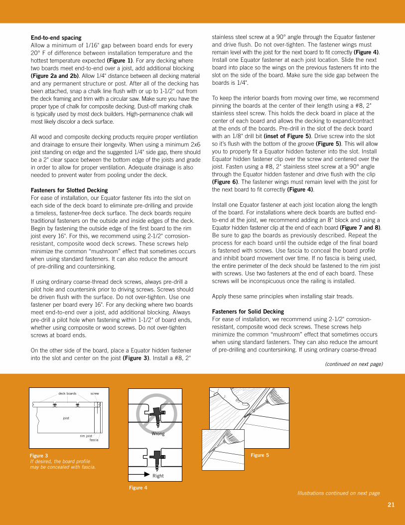
End-to-end spacingAllow a minimum of 1/16" gap between board ends for every 20°Fofdifferencebetweeninstallationtemperatureandthe hottest temperature expected (Figure 1). For any decking where two boards meet end-to-end over a joist, add additional blocking (Figure 2a and 2b). Allow 1/4" distance between all decking material and any permanent structure or post. After all of the decking has been attached, snap a chalk line flush with or up to 1-1/2" out from the deck framing and trim with a circular saw. Make sure you have the proper type of chalk for composite decking. Dust-off marking chalk is typically used by most deck builders. High-permanence chalk will most likely discolor a deck surface. All wood and composite decking products require proper ventilation and drainage to ensure their longevity. When using a minimum 2x6 joist standing on edge and the suggested 1/4" side gap, there should be a 2" clear space between the bottom edge of the joists and grade in order to allow for proper ventilation. Adequate drainage is also needed to prevent water from pooling under the deck.
Fasteners for Slotted DeckingFor ease of installation, our Equator fastener fits into the slot on each side of the deck board to eliminate pre-drilling and provide a timeless, fastener-free deck surface. The deck boards require traditional fasteners on the outside and inside edges of the deck. Begin by fastening the outside edge of the first board to the rim joist every 16". For this, we recommend using 2-1/2" corrosion-resistant, composite wood deck screws. These screws help minimize the common “mushroom” effect that sometimes occurs when using standard fasteners. It can also reduce the amount of pre-drilling and countersinking.
If using ordinary coarse-thread deck screws, always pre-drill a pilot hole and countersink prior to driving screws. Screws should be driven flush with the surface. Do not over-tighten. Use one fastener per board every 16". For any decking where two boards meet end-to-end over a joist, add additional blocking. Always pre-drill a pilot hole when fastening within 1-1/2" of board ends, whether using composite or wood screws. Do not over-tighten screws at board ends.
On the other side of the board, place a Equator hidden fastener into the slot and center on the joist (Figure 3). Install a #8, 2"
stainlesssteelscrewata90°anglethroughtheEquatorfastenerand drive flush. Do not over-tighten. The fastener wings must remain level with the joist for the next board to fit correctly (Figure 4). Install one Equator fastener at each joist location. Slide the next board into place so the wings on the previous fasteners fit into the slot on the side of the board. Make sure the side gap between the boards is 1/4".
To keep the interior boards from moving over time, we recommend pinning the boards at the center of their length using a #8, 2" stainless steel screw. This holds the deck board in place at the center of each board and allows the decking to expand/contract attheendsoftheboards.Pre-drillintheslotofthedeckboardwith an 1/8" drill bit (inset of Figure 5). Drive screw into the slot so it’s flush with the bottom of the groove (Figure 5). This will allow you to properly fit a Equator hidden fastener into the slot. Install Equator hidden fastener clip over the screw and centered over the joist.Fastenusinga#8,2"stainlesssteelscrewata90°anglethrough the Equator hidden fastener and drive flush with the clip (Figure 6). The fastener wings must remain level with the joist for the next board to fit correctly (Figure 4).
Install one Equator fastener at each joist location along the length of the board. For installations where deck boards are butted end-to-end at the joist, we recommend adding an 8" block and using a Equator hidden fastener clip at the end of each board (Figure 7 and 8). Be sure to gap the boards as previously described. Repeat the process for each board until the outside edge of the final board is fastened with screws. Use fascia to conceal the board profile and inhibit board movement over time. If no fascia is being used, the entire perimeter of the deck should be fastened to the rim joist with screws. Use two fasteners at the end of each board. These screws will be inconspicuous once the railing is installed.
Apply these same principles when installing stair treads.
Fasteners for Solid DeckingFor ease of installation, we recommend using 2-1/2" corrosion-resistant, composite wood deck screws. These screws help minimize the common “mushroom” effect that sometimes occurs when using standard fasteners. They can also reduce the amount of pre-drilling and countersinking. If using ordinary coarse-thread
Figure 3 If desired, the board profile may be concealed with fascia.
joist
deck boards
rim joistfascia
screw
Fig.2.eps
Fig.1.eps
Figure 5
Illustrations continued on next page
(continued on next page)

Fig. 5.eps
Figure 7
Fig. 7.eps
Figure 8
The appearance of composite decking changes when viewed from different ends. To achieve the most consistent color, install all of the boards in the same direction using the prod-uct end tags (A) as a point of reference, or install all of the boards with the arrows on the product stickers (B) pointing in the same direction. Installing boards in opposing directions will create contrasting light and dark shades of the deck board color and is not covered under warranty.
Priortoconstruction,checkwithyourlocalregulatoryagencyforspecial code requirements in your area. For best results, follow these simple installation instructions, paying close attention to gapping, spacing and fastener requirements.
Joist span 16" on-center for residential perpendicular applications. Residential parquet patterns and diagonal or herringbone designs all require joist spacing 12" on-center. Contact Equator product support at 877-463-8379 for commercial applications.
Side gapping: 1/4".
End-to-end spacingAllow a minimum of 1/16" gap between board ends for every 20°Fofdifferencebetweeninstallationtemperatureandthe hottest temperature expected (Figure 1). For any decking where two boards meet end-to-end over a joist, add additional blocking (Figure 2a and 2b). Allow 1/4" distance between all decking material and any permanent structure or post. After all of the decking has been attached, snap a chalk line flush with or up to 1-1/2" out from the deck framing and trim with a circular saw. Make sure you have the proper type of chalk for composite decking. Dust-off marking chalk is typically used by most deck builders. High-permanence chalk will most likely discolor a deck surface. All wood and composite decking products require proper ventilation and drainage to ensure their longevity. When using a minimum 2x6 joist standing on edge and the suggested 1/4" side gap, there should be a 2" clear space between the bottom edge of the joists and grade in order to allow for proper ventilation. Adequate drain-age is also needed to prevent water from pooling under the deck.
Fasteners for Slotted DeckingFor ease of installation, our Equator fastener fits into the slot on each side of the deck board to eliminate pre-drilling and provide a timeless, fastener-free deck surface. The deck boards require traditional fasteners on the outside and inside edges of the deck. Begin by fastening the outside edge of the first board to the rim joist every 16". For this, we recommend using 2-1/2" corrosion-resistant, composite wood deck screws. These screws help minimize the common “mushroom” effect that sometimes occurs when using standard fasteners. It can also reduce the amount of pre-drilling and countersinking.
If using ordinary coarse-thread deck screws, always pre-drill a pilot hole and countersink prior to driving screws. Screws should be driven flush with the surface. Do not over-tighten. Use one fastener per board every 16". For any decking where two boards meet end-to-end over a joist, add additional blocking. Always pre-drill a pilot hole when fastening within 1-1/2" of board ends, whether using composite or wood screws. Do not over-tighten screws at board ends.
On the other side of the board, place a Equator hidden fastener into the slot and center on the joist (Figure 3). Install a #8, 2" stainlesssteelscrewata90°anglethroughtheEquatorfastenerand drive flush. Do not over-tighten. The fastener wings must remain level with the joist for the next board to fit correctly (Figure 4). Install one Equator fastener at each joist location. Slide the next board into place so the wings on the previous fasteners fit into the slot on the side of the board. Make sure the side gap between the boards is 1/4".
To keep the interior boards from moving over time, we recommend pinning the boards at the center of their length using a #8, 2" stainless steel screw. This holds the deck board in place at the center of each board and allows the decking to expand/contract attheendsoftheboards.Pre-drillintheslotofthedeckboardwith an 1/8" drill bit (inset of Figure 5). Drive screw into the slot so it’s flush with the bottom of the groove (Figure 5). This will allow you to properly fit a Equator hidden fastener into the slot. Install Equator hidden fastener clip over the screw and centered over the joist.Fastenusinga#8,2"stainlesssteelscrewata90°angle
22
Fig.4.eps
Figure 6

23
through the Equator hidden fastener and drive flush with the clip (Figure 6). The fastener wings must remain level with the joist for the next board to fit correctly (Figure 4).
Install one Equator fastener at each joist location along the length of the board. For installations where deck boards are butted end-to-end at the joist, we recommend adding an 8" block and using a Equator hidden fastener clip at the end of each board (Figure 7 and 8). Be sure to gap the boards as previously described. Repeat the process for each board until the outside edge of the final board is fastened with screws. Use fascia to conceal the board profile and inhibit board movement over time. If no fascia is being used, the entire perimeter of the deck should be fastened to the rim joist with screws. Use two fasteners at the end of each board. These screws will be inconspicuous once the railing is installed.
Apply these same principles when installing stair treads.
Fasteners for Solid DeckingFor ease of installation, we recommend using 2-1/2" corrosion-resistant, composite wood deck screws. These screws help minimize the common “mushroom” effect that sometimes occurs when using standard fasteners. They can also reduce the amount of pre-drilling and countersinking. If using ordinary coarse-thread deck screws, always pre-drill a pilot hole and countersink prior to driving screws. Screws should be driven flush with the Latitudes surface. Do not over-tighten. Use two fasteners per deck board at each joist. For any decking where two boards meet end-to-end over a joist, add additional blocking (see Figure 2b). Always pre-drill a pilot hole and countersink at board ends when using composite or wood screws. Be careful not to over-tighten screws near board ends.
Snap a chalk line to keep the fastener pattern straight. Make sure you have the proper type of chalk for composite decking. Dust- off marking chalk is typically used by most deck builders. High- permanence chalk will most likely discolor a deck surface.
Color VariationLike most composites, Latitudes Intrepid™ decking will have color variations from piece to piece. This is due to naturally occurring variations in wood fibers and polymers. Latitudes Captiva™ features a cap stock material over a wood composite core. The cap stock improves color consistency and makes the decking extremely fade-resistant. Latitudes Capricorn® decking also features an innova-tive cap stock material with excellent fade-resistant properties. However, color variation is a distinct feature of Latitudes Capricorn decking. Each board has a unique appearance and should be arranged according to the end user’s preference. Do not install ifcolorvariationisnotacceptabletotheenduser.Purchasingall required decking material at one time is recommended, as manufacturing runs can produce slightly different colors Latitudes Intrepid decking will lighten over time, and color variation is not covered by the warranty. This color-tone shift is dependent upon exposure to sunlight and other environmental factors, and is gener-ally completed in 60 to 90 days. Gray products may turn a light brown before changing to lighter gray.
Preventing mold and mildew growth on composite deckingMold and mildew can be a nuisance on any exterior building surface, regardless of the material. If the conditions are right, they will spawn on wood, plastic, concrete, metal and other surfaces. Mold formation is most prevalent in consistently wet, shaded areas. Spores from the natural environment are carried by the wind and commonly land on decks surfaces. It is important to note that the appearance of mold/mildew is a function of nature, not necessarily a deficiency with any of the material on which it grows.
CleaningPeriodicwashingwithsoap/detergentandwaterwillhelpremovesurface dirt. This will also help prevent the buildup of pollen, debris and spores that can cause and accelerate mold/mildew growth. Caution: A pressure washer should not be used to “blast” mold/mildew or soils from a deck surface. The abrasive nature of the water stream can potentially damage the material by driving the spores into the material, which may create a more challenging problem to remediate. A pressure washer with a fan-tipped nozzle should be used only to lightly wet or rinse wood or composite deck surfaces.
There are many deck wash and exterior cleaning products available at retail. It is important to make sure you use a cleaner specifically intended for your application. After selecting a product, be certain to read, understand and follow all instructions supplied by the manufacturer. Some cleaning products and inhibitors may be more effective than others, depending on the environmental conditions your deck is subjected to. Additionally, it is always a good idea to test the cleaner in a small, inconspicuous area prior to applying it to the entire deck.
Mold InhibitorsAs with deck washes, there are several mold-inhibitor products available from paint stores, hardware stores, online outlets and home centers to help minimize long-term mold/mildew growth. For any product selected, be certain to read, understand and follow all instructions provided by the manufacturer. Depending upon the environmental factors affecting your deck, some preventive cleaning products may be more effective than others. It may be necessary to try more than one product. For ongoing preventive maintenance, follow the manufacturer’s recommendation.

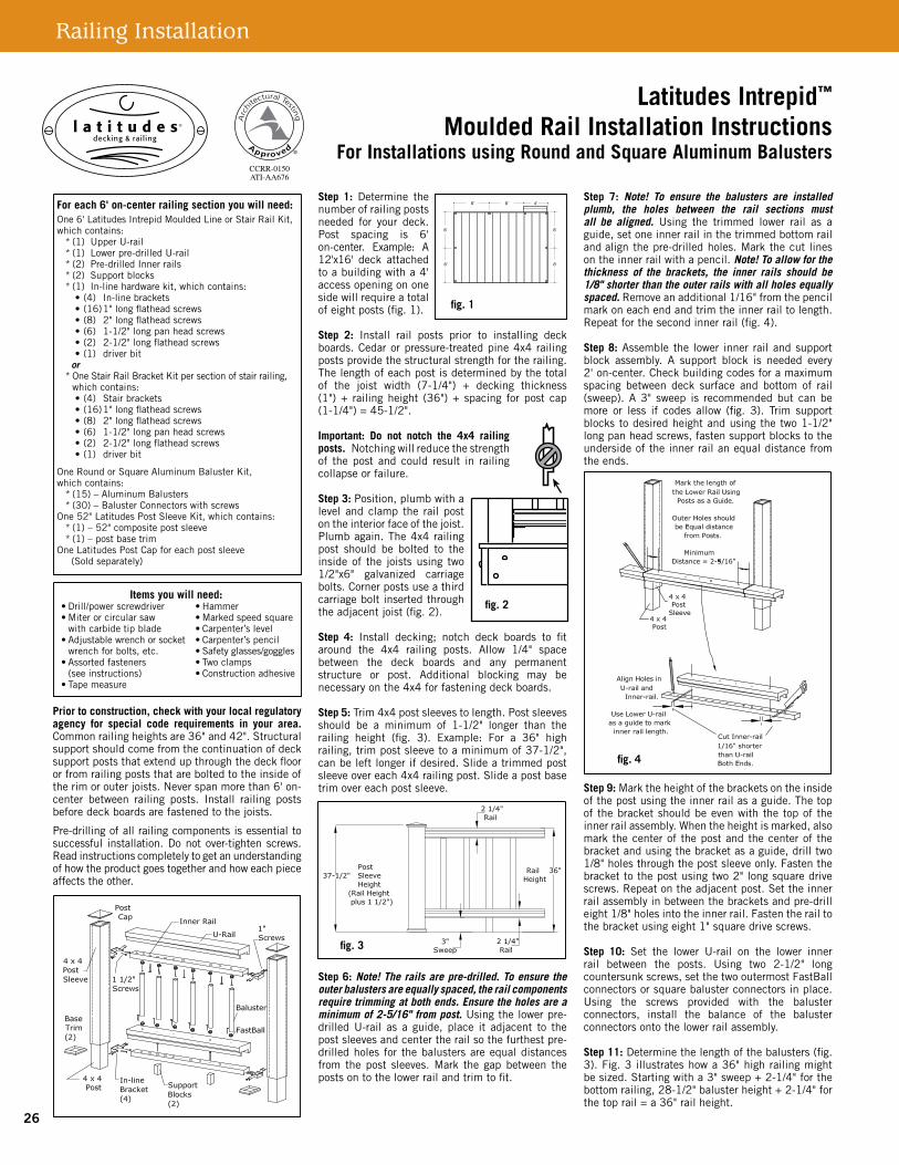
For each 6' on-center railing section you will need:One 6' Latitudes Intrepid Moulded Line or Stair Rail Kit, which contains:
* (1) Upper U-rail * (1) Lower pre-drilled U-rail * (2) Pre-drilled inner rails * (2) Support blocks * (1) In-line hardware kit, which contains: •(4) In-linebrackets •(16)1"longflatheadscrews •(8) 2"longflatheadscrews •(6) 1-1/2"longpanheadscrews •(2) 2-1/2"longflatheadscrews •(1) driverbit or
*OneStairRailBracketKitpersectionofstairrailing, which contains: •(4) Stairbrackets •(16)1"longflatheadscrews •(8) 2"longflatheadscrews •(6) 1-1/2"longpanheadscrews •(2) 2-1/2"longflatheadscrews •(1) driverbitOne Composite Baluster Kit, which contains:
*(15)–38"compositebalusters *(32)–1-3/4"longpanheadscrewsOne52"LatitudesPostSleeveKit,whichcontains:
*(1)–52"compositepostsleeve * (1) – Post base trimOneLatitudesPostCapforeachPostSleeve (sold separately)
Prior to construction, check with your local regulatory agency for special code requirements in your area. Commonrailingheightsare36"and42".Structuralsupport should come from the continuation of deck supportpoststhatextendupthroughthedeckflooror fromrailingposts thatarebolted to the insideoftherimorouterjoists.Neverspanmorethan6'on-centerbetweenrailingposts.Installrailingpostsbeforedeckboardsarefastenedtothejoists.
Pre-drilling of all railing components is essentialto successful installation. Do not over-tightenscrews. Read instructions completely to get anunderstanding of how the product goes togetherandhoweachpieceaffectstheother.
Step 1:Determine thenumberofrailingpostsneededforyourdeck.Post spacing is 6' oncenter. Example: A12'x16' deck attached toabuildingwitha4'accessopeningononeside will require a total ofeightposts(fig.1).
Step 2: Install rail posts prior to installing deckboards.Cedarorpressure-treatedpine4x4railingpostsprovidethestructuralstrengthfortherailing.Thelengthofeachpostisdeterminedbythetotalof the joist width (7-1/4") + decking thickness(1")+ railingheight (36")+ spacing forpostcap (1-1/4")=45-1/2".
Important: Do not notch the 4x4 railing posts.Notchingwillreducethestrengthofthepostandcouldresult inrailingcollapseorfailure.
Step 3: Position, plumb with a levelandclamptherailposton the interior face of the joist. Plumb again. The 4x4railingpostshouldbeboltedto the inside of the joists usingtwo1/2"x6"galvanizedcarriage bolts. Corner postsuse a third carriage boltinsertedthroughtheadjacentjoist(fig.2).
Step 4: Install decking; notch deck boards to fitaround the 4x4 railing posts. Allow 1/4" spacebetween the deck boards and any permanent structure or post. Additional blocking may benecessaryonthe4x4forfasteningdeckboards.
Step 5:Trim4x4postsleevestolength.Postsleevesshould be a minimum of 1-1/2" longer than therailing height (fig. 3). Example: For a 36" highrailing,trimpostsleevetoaminimumof37-1/2".Canbeleftlongerifdesired.Slideatrimmedpostsleeveovereach4x4railingpost.Slideapostbasetrimovereachpostsleeve.
Step 6: Note! To ensure the outer balusters are equally spaced, the rail components require trimming at both ends. Usingthelowerpre-drilledU-railasaguide,placeitadjacenttothepostsleevesandcentertherail so the furthest pre-drilled holes for the balusters areequaldistances from thepost sleeves. Ensure the holes are a minimum of 2-5/16" from each post. MarkthegapbetweenthepostsontotheU-railandtrimtofit(fig.4).
Step 7: Note! To ensure the balusters are installed plumb, the holes between the rail sections must all be aligned.Usingthetrimmedlowerrailasaguide,setoneinnerrailinthetrimmedbottomrailandalignthepre-drilledholes.Pencilmarkthecutlengthontheinnerrail.Note! To allow for the thickness of the brackets, the inner rails should be 1/8" shorter than the U-rails with all holes equally spaced. Removeanadditional1/16"fromthepencilmarkoneachendand trim the inner rail to length. Repeat for thesecondinnerrail.
Step 8:Assemblethe lower inner railandsupportblock section. A support block is needed every2' on-center. Check building codes for maximumspacing between deck surface and bottom of rail(sweep). A3" sweep is recommended, but it canbemoreorlessifcodesallow(fig.3).Trimsupportblockstodesiredheightandpre-drillwith1/8"drillbit.Usingtwo1-1/2"longpanheadscrews,fastensupport blocks to the underside of the inner rail an equaldistancefromtheends.
Step 9: Set the lower assembly in place between theposts.Mark theheight to install thebracketsontheinsideofthepostusingtheinnerrailasaguide.Thetopofthebracketshouldbeevenwiththetopoftheinnerrailassembly.Whentheheightis marked, also mark the center of the post and the centerofthebracket.Usingthebracketasaguide,drill two 1/8" holes through the post sleeve only.Fasten the bracket to the post using two2" longsquaredrivescrews.Repeatontheadjacentpost.Set the inner rail assembly in place and pre-drill eight1/8"holesintotheinnerrail.Fastentherailtothebracketusingeight1"squaredrivescrews.
Step 10: Determine the length of the balusters(fig. 3). Fig. 3 illustrates how a 36" high railingmightbesized.Startingwitha3"sweep+2-1/4"forthebottomrailing,+28-1/2"balusterheight+ 2-1/4"forthetoprail=a36"railheight.Ifthesearethedimensionsthatyouaregoingtouse,cutthebalustersto28-1/2"lengthusingacut-offortablesaw.Use34-1/2"balustersfor42"railings.Ifyouwanttohaveyourrailingatadifferentheight,usefig.3asaplanningtooltodeterminetheheighttocutthepostsleevesandthebalusters.Note: Use a fixture to ensure a consistent length (+/- 1/16”).
Latitudes Intrepid™
Moulded Rail Installation InstructionsFor Installations using Composite Balusters
6' 6'
6'6'
6' 6' 4'
•
•
•
• • • •
•
•
•
PAGE 1 - Composite Balusters
fig. 1
fig. 2
fig. 4
fig. 3
Items you will need: •Drill/powerscrewdriver •Hammer •Miterorcircularsaw •Markedspeedsquare withcarbidetipblade •Carpenter’slevel •Adjustablewrenchorsocket •Carpenter’spencil wrenchforbolts,etc. •Safetyglasses/goggles •Assortedfasteners •Twoclamps (seeinstructions) •Constructionadhesive •Tapemeasure
Railing Installation
24

Trimthebalusterstotherequiredlength.Pre-drilltheendsofthebalustersusinga1/8"drillbit.Setthebalustersbetweentheremaininginnerrailandthe lower U-rail section and fasten in place with the pan head screws included with the Baluster Kit. The balusters should fit in the groove in theunderside of the inner rail to prevent them fromspinningonceassembled.
Step 11: Set the baluster assembly on the lower inner rail(fig.5).Marktheheighttoinstallthebracketsontheinsideofthepostusingtheinnerrailasaguide.Thetopofthebracketshouldbeevenwiththetopoftheinnerrailassembly.Whentheheightis marked, also mark the center of the post and the centerofthebracket.Usingthebracketasaguide,drill two 1/8" holes through the post sleeve only.Fasten the bracket to the post using two2" longsquaredrivescrews.Repeatontheadjacentpost.Set the inner rail assembly in place and pre-drill eight1/8"holesintotheinnerrail.Fastentherailtothebracketusingeight1"squaredrivescrews.
Step 12: Measure the distance between the posts, trimtheupperU-railtolengthandsettherailonthe assembly. Taking care not to drill all the way through the rail, usea1/8"drillbittocarefullypre-drillthroughfouroftheinnerrailholes1/2"deepdirectly into the underside of the upper cap rail.Fasten U-rail in place using the four 1-1/2" panheadscrews.
Step 13:Applyconstructionadhesivetotheinsideedges of the post caps and place over each postsleeve.
Stair Railing Installation InstructionsStep 1:Cedarorpressure-treatedpine4x4 railingpostsprovidethestructuralstrengthfortherailing.Thelengthofeachpostisdeterminedbythetotalofthestairstringerwidth(7-1/4")+treadthickness(1")+railingheight(36")+spacingforpostcap(1-1/4")=45-1/2".
Step 2:Position,plumbwithalevelandclamptherail post on the interior face of the stair stringer.Plumbagain.The4x4railingpostshouldbeboltedtotheinsideofthestairstringerusingtwo1/2"x6"galvanizedcarriagebolts.Cornerpostsuseathirdcarriage bolt inserted through the adjacent joist.Groundlevelpostsshouldbesetinconcrete.
Step 3: Complete stair tread installation prior to installing post sleeves. Trim 4x4 post sleeves tolength. Post sleeves should be a minimum of 1-1/2" longer than the railing height. Slide atrimmed post sleeve over each 4x4 railing post.Slideapostbasetrimovereachpostsleeve.
Step 4: Note! As the holes in the rails are pre-drilled, the rail components require trimming at both ends to ensure the outer balusters are equally spaced.Usingthe lower pre-drilled U-rail as a guide, place itadjacentthepostsleevesandcentertherailsothefurthest pre-drilled holes for the balusters are equal distances from the post sleeves. Ensure the holes are a minimum of 2-5/16" from each post.Usingthepostsasaguide,marktheangleforthebeveledcutverticallythroughtheU-railsection(fig.6).
Step 5: Note! To ensure the balusters are installed plumb, the holes between the rail sections must all be aligned. Using the trimmed lower rail as a guide, set the up per inner rail for the system on top of thetrimmedbottomrailandalignthepre-drilledholes.PencilmarkthecutlengthontheInnerrail.Repeatforthesecondinnerrail.Note! To allow for the thickness of the brackets, the inner rails should be 1/8" shorter than the U-rails with all holes equally spaced. Removeanadditional1/16"fromthepencilmarkoneachendandtrimtheinnerrailtolength.Repeatforthesecondinnerrail.
Step 6:Assemblethe lower inner railandsupportblock assembly. Position the bottom rail betweenthe posts. Check building code requirements formaximum spacing on a staircase, typically lessthan6".A6"ballcannotpassthroughthetriangleformedbythebottomrail,treadandriser(seefig.7).A supportblock isneededevery2' on-center.Trim support blocks to desired height and fastenthem to the underside of the inner rail equal distance from the ends. Use the two 1-1/2" longpanheadscrews.
Step 7:Marktheheightofthebracketsontheinsideofthepostusingtheinnerrailasaguide.Thetopofthebracketshouldbeevenwiththetopoftheinner rail assembly. When the height is marked,also mark the center of the post and the center of thebracket.Usingthebracketasaguide,drilltwo1/8"holesthroughthepostsleeveonly.Fastenthebrackettothepostusingeight2"longsquaredrivescrews.Repeatontheadjacentpost.Settheinnerrail assembly in between the brackets and pre-drill eight1/8"holesintotheinnerrail.Usingeight1"squaredrivescrews,fastentherailinplace.
Step 8:Determinethelengthofthebalusters(fig.3).Fig.3illustrateshowa36"highrailingmightbesized.Startingwitha3"sweep+2-1/4"forthebottomrailing,+28-1/2"balusterheight+2-1/4"
for the top rail = a 36" rail height. If these arethedimensionsthatyouaregoingtouse,cutthebalustersto28-1/2"lengthusingacut-offortablesaw.Use34-1/2"balustersfor42"railings.Ifyouwanttohaveyourrailingatadifferentheight,usefig.3asaplanningtooltodeterminetheheighttocut the post sleeves and the balusters.Note: Use a fixture to ensure a consistent length (+/- 1/16"). Trimthebalusterstotherequiredlengthandangle.Pre-drill the ends of the balusters using a 1/8"drillbit.Set thebalustersbetween the remaininginner rail and the lower U-rail section and fasten in place with the pan head screws included with the BalusterKit.Thebalustersshouldfitinthegrooveintheundersideoftheinnerrail topreventthemfromspinningonceassembled.
Step 9: Set the lower assembly in place between theposts.Mark theheight to install thebracketsontheinsideofthepostusingtheinnerrailasaguide.Thetopofthebracketshouldbeevenwiththetopoftheinnerrailassembly.Whentheheightis marked, also mark the center of the post and thecenterof thebracket.Using thebracketasaguide,drilltwo1/8"holesthroughthepostsleeve.Fasten the bracket to the post using two2" longsquaredrivescrews.Repeatontheadjacentpost.Set the inner rail assembly in place and pre-drill eight1/8"holesintotheinnerrail.Fastentherailtothebracketusingeight1"squaredrivescrews.
Step 10: Measure the distance between the posts andtrimtheupperU-railtolengthandangle,andsetontheassembly.Taking care not to drill all the way through the rail,usea1/8"drillbittocarefullypre-drill through four of the inner rail holes 1/2"deep directly into the underside of the upper cap rail. Fasten U-rail in place using the four 1-1/2"panheadscrews.
Step 11:Applyconstructionadhesivetotheinsideedges of the post caps and place over each postsleeve.
Latitudes isnotsuitable forstructuraluse. Itshouldnotbeusedforprimaryload-bearingmemberssuchasposts,joists, beams or stringers. The same common senseprecautionsshouldbe takenwhenhandlingLatitudesaswith wood or other building materials. Dust masks andeyeprotectiondevicesarerecommendedtoavoidpossibleirritation from sawdust and chips. Gloves will help toprotect the hands. Hands should be washed after doingconstructionwork.
The diagrams and instructions in this brochure are forillustration purposes only and are not meant to replace a licensed professional. Any construction or use of theproduct must be in accordance with all local zoningand/or building codes. The consumer assumes all risksand liability associated with the construction or use of thisproduct.Theconsumerorcontractorshould takeallnecessarystepstoensurethesafetyofeveryoneinvolvedin theproject, including,butnot limited to,wearing theappropriate safety equipment. EXCEPT AS CONTAINED IN THE WRITTEN LIMITED WARRANTY, WARRANTOR DOES NOT PROVIDE ANY OTHER WARRANTY, EITHER EXPRESS OR IMPLIED, AND SHALL NOT BE LIABLE FOR ANY DAMAGES, INCLUDING CONSEQUENTIAL DAMAGES.
ManufacturedbyUFPVenturesII,Inc.,aUniversalForestProductsCompany
1801E.Lessard,PrairieduChien,WI53821877.463.8379
www.latitudesdeck.com©2010 Universal Forest Products, Inc. All rights reserved. Latitudes is a registered trademark of Universal Forest Products, Inc. in the U.S. and other countries. Latitudes Intrepid is a trademark of Universal Consumer Products, Inc., in the U.S. The Architectural Testing Approved logo is registered trademark of Architectural Testing, Inc.
6053 G2 Comp ENG_5/10
PAGE 2 - Composite Balusters
fig. 6
fig. 7
fig. 5
25
26
For each 6' on-center railing section you will need:One 6' Latitudes Intrepid Moulded Line or Stair Rail Kit, which contains:
* (1) Upper U-rail * (1) Lower pre-drilled U-rail * (2) Pre-drilled Inner rails * (2) Support blocks * (1) In-line hardware kit, which contains: •(4) In-linebrackets •(16)1"longflatheadscrews •(8) 2"longflatheadscrews •(6) 1-1/2"longpanheadscrews •(2) 2-1/2"longflatheadscrews •(1) driverbit or
*OneStairRailBracketKitpersectionofstairrailing, which contains: •(4) Stairbrackets •(16)1"longflatheadscrews •(8) 2"longflatheadscrews •(6) 1-1/2"longpanheadscrews •(2) 2-1/2"longflatheadscrews •(1) driverbit
One Round or Square Aluminum Baluster Kit,which contains:
* (15) – Aluminum Balusters * (30) – Baluster Connectors with screwsOne52"LatitudesPostSleeveKit,whichcontains:
*(1)–52"compositepostsleeve * (1) – post base trimOneLatitudesPostCapforeachpostsleeve (Sold separately)
Prior to construction, check with your local regulatory agency for special code requirements in your area. Commonrailingheightsare36"and42".Structuralsupport should come from the continuation of deck supportpoststhatextendupthroughthedeckfloororfromrailingpoststhatareboltedtotheinsideoftherimorouterjoists.Neverspanmorethan6'on-center between railing posts. Install railing postsbeforedeckboardsarefastenedtothejoists.
Pre-drillingofallrailingcomponentsisessentialtosuccessful installation.Donotover-tightenscrews.Readinstructionscompletelytogetanunderstandingofhowtheproductgoestogetherandhoweachpieceaffectstheother.
Step 1: Determine thenumberofrailingpostsneeded for your deck.Post spacing is 6'on-center. Example: A12'x16' deck attached toabuildingwitha4'accessopeningononeside will require a total ofeightposts(fig.1).
Step 2: Install rail posts prior to installing deckboards.Cedarorpressure-treatedpine4x4railingpostsprovidethestructuralstrengthfortherailing.Thelengthofeachpostisdeterminedbythetotalof the joist width (7-1/4") + decking thickness(1")+ railingheight (36")+ spacing forpostcap (1-1/4")=45-1/2".
Important: Do not notch the 4x4 railing posts.Notchingwillreducethestrengthof thepost andcould result in railingcollapseorfailure.
Step 3: Position, plumb with a level andclamp the railpostontheinteriorfaceofthejoist.Plumbagain.The4x4railingpost should be bolted to the insideof the joistsusing two1/2"x6" galvanized carriagebolts.Cornerpostsuseathirdcarriageboltinsertedthroughtheadjacentjoist(fig.2).
Step 4: Install decking; notch deck boards to fitaround the 4x4 railing posts. Allow 1/4" spacebetween the deck boards and any permanent structure or post. Additional blocking may benecessaryonthe4x4forfasteningdeckboards.
Step 5:Trim4x4postsleevestolength.Postsleevesshould be a minimum of 1-1/2" longer than therailing height (fig. 3). Example: For a 36" highrailing,trimpostsleevetoaminimumof37-1/2",canbeleftlongerifdesired.Slideatrimmedpostsleeveovereach4x4railingpost.Slideapostbasetrimovereachpostsleeve.
Step 6: Note! The rails are pre-drilled. To ensure the outer balusters are equally spaced, the rail components require trimming at both ends. Ensure the holes are a minimum of 2-5/16" from post.Usingthelowerpre-drilledU-rail as a guide, place it adjacent to thepostsleevesandcentertherailsothefurthestpre-drilled holes for the balusters are equal distances from thepost sleeves.Mark thegapbetween thepostsontothelowerrailandtrimtofit.
Step 7: Note! To ensure the balusters are installed plumb, the holes between the rail sections must all be aligned. Using the trimmed lower rail as aguide,setoneinnerrailinthetrimmedbottomrailandalignthepre-drilledholes.Markthecutlinesontheinnerrailwithapencil.Note! To allow for the thickness of the brackets, the inner rails should be 1/8" shorter than the outer rails with all holes equally spaced. Removeanadditional1/16"fromthepencilmarkoneachendandtrimtheinnerrailtolength.Repeatforthesecondinnerrail(fig.4).
Step 8: Assemble the lower inner rail and support block assembly. A support block is needed every2'on-center.Checkbuildingcodesforamaximumspacing between deck surface and bottom of rail(sweep).A3" sweep is recommendedbutcanbemore or less if codes allow (fig. 3). Trim supportblockstodesiredheightandusingthetwo1-1/2"longpanheadscrews,fastensupportblockstotheunderside of the inner rail an equal distance from theends.
Step 9:Marktheheightofthebracketsontheinsideofthepostusingtheinnerrailasaguide.Thetopofthebracketshouldbeevenwiththetopoftheinnerrailassembly.Whentheheightismarked,alsomark the center of the post and the center of the bracketandusingthebracketasaguide,drilltwo1/8"holesthroughthepostsleeveonly.Fastenthebrackettothepostusingtwo2"longsquaredrivescrews.Repeatontheadjacentpost.Settheinnerrail assembly in between the brackets and pre-drill eight1/8"holesintotheinnerrail.Fastentherailtothebracketusingeight1"squaredrivescrews.
Step 10: Set the lower U-rail on the lower inner rail between the posts. Using two 2-1/2" longcountersunkscrews,setthetwooutermostFastBallconnectorsorsquarebalusterconnectorsinplace.Using the screws provided with the balusterconnectors, install the balance of the baluster connectorsontothelowerrailassembly.
Step 11:Determinethelengthofthebalusters(fig.3).Fig.3illustrateshowa36"highrailingmightbesized.Startingwitha3"sweep+2-1/4"forthebottomrailing,28-1/2"balusterheight+2-1/4"forthetoprail=a36"railheight.
Latitudes Intrepid™
Moulded Rail Installation InstructionsFor Installations using Round and Square Aluminum Balusters
6' 6'
6'6'
6' 6' 4'
•
•
•
• • • •
•
•
•
PAGE 1 - Round and Square Aluminum Balusters
fig. 1
fig. 2
fig. 3
fig. 4
Items you will need: •Drill/powerscrewdriver •Hammer •Miterorcircularsaw •Markedspeedsquare withcarbidetipblade •Carpenter’slevel •Adjustablewrenchorsocket •Carpenter’spencil wrenchforbolts,etc. •Safetyglasses/goggles •Assortedfasteners •Twoclamps (seeinstructions) •Constructionadhesive •Tapemeasure
Railing Installation

Ifthesearethedimensionsthatyouaregoingtouse,cutthebalustersto28-1/2"lengthusingacut-offormitersaw.Use34-1/2"balustersfor42"railings.Ifyouwanttohaveyourrailingatadifferentheight,usefig.3asaplanningtooltodeterminetheheighttocutthepostsleevesandthebalusters,Note: Use a fixture to ensure a consistent length (+/- 1/16").Trim the balusters to the required length. Installbalusters on each baluster connector. Gently tapthe balusters with a rubber mallet to eliminate any gaps.Checkforlevelendtoend.
Step 12: Install theFastBallconnectorsorsquarebaluster connectors on the underside of the top innerrail(fig.6).Settherailontothebalusters,gently tapping the rail to remove any gaps. Markthe height of the brackets on the inside of thepostusingtheinnerrailasaguide.Thetopofthebracketshouldbeevenwiththetopoftheinnerrailassembly.Whentheheightismarked,alsomarkthecenter of the post and the center of the bracket and using thebracketasaguide,drill two1/8"holesthroughthepostsleeve.Fastenthebrackettothepostusingtwo2"longsquaredrivescrews.Repeatontheadjacentpost.Settheinnerrailassemblyinbetweenthebracketsandpre-drilleight1/8"holesinto the inner rail. Fasten the rail to the bracketusingeight1"squaredrivescrews.
Step 13: Measure the distance between the posts and trim the upper top rail to length and set onthe assembly. Taking care not to drill all the way through the rail,usea1/8"drillbittocarefullypre-drillthroughfouroftheinnerrailholes1/2"deepdirectly in to theundersideof theuppercaprail.Fastencaprailinplaceusingthefour1-1/2"panheadscrews.
Step 14:Applyconstructionadhesivetotheinsideedges of the post caps and place over each postsleeve.
Stair Railing Installation InstructionsStep 1:Cedarorpressure-treatedpine4x4 railingpostsprovidethestructuralstrengthfortherailing.Thelengthofeachpostisdeterminedbythetotalofthestairstringerwidth(7-1/4")+treadthickness(1")+railingheight(36")+spacingforpostcap(1-1/4")=45-1/2".
Step 2:Position,plumbwithalevelandclamptherail post on the interior face of the stair stringer.Plumbagain.The4x4railingpostshouldbeboltedtotheinsideofthestairstringerusingtwo1/2"x6"galvanizedcarriagebolts.Cornerpostsuseathirdcarriage bolt inserted through the adjacent joist.Groundlevelpostsshouldbesetinconcrete.
Step 3: Complete stair tread installation prior to installing post sleeves. Trim 4x4 post sleeves tolength.Postsleevesshouldbeaminimumof1-1/2"longerthantherailingheight.Slideatrimmedpostsleeveovereach4x4railingpost.Slideapostbasetrimovereachpostsleeve.
Step 4: Note! The rails are pre-drilled. To ensure the outer balusters are equally spaced, the rail components require trimming at both ends. Usingthelowerpre-drilledU-railasaguide,placeitadjacentthepost
sleevesandcentertherailsothefurthestpre-drilledholes for the balusters are equal distances from the postsleeves.Usingthepostsasaguide,marktheangleforthebeveledcutverticallythroughtheU-railsection.MarkthegapbetweenthepostsontotheU-railandtrimtofit.
Step 5: Note! To ensure the balusters are installed plumb, the holes between the rail sections must all be aligned.Usingthetrimmedlowerrailasaguide,set the upper inner rail for the system on top of the trimmedbottomrailandalignthepre-drilledholes.Pencilmarkthecutlengthontheinnerrail.Note! To allow for the thickness of the brackets, the inner rails should be 1/8" shorter than the U-rails with all holes equally spaced. Removean additional1/16"from the pencil mark on each end and trim the inner rail to length. Repeat for the second innerrail(fig.6).
Step 6: Assemble the lower inner rail and support block assembly. Position the bottom rail betweenthe posts. Check building code requirements formaximum spacing on a staircase, typically lessthan6".A6"ballcannotpassthroughthetriangleformedbythebottomrail,treadandriser.Seefig.8. A support block is needed every 2' on-center.Trimsupportblockstodesiredheight.Usinga1/8"drill bit, pre-drill the blocks and attach them to the underside of the inner rail equal distance from the ends.Usethetwo1-1/2"longpanheadscrews.
Step 7:Marktheheightofthebracketsontheinsideofthepostusingtheinnerrailasaguide.Thetopofthebracketshouldbeevenwiththetopoftheinner rail assembly. When the height is marked,also mark the center of the post and the center of thebracketandusingthebracketasaguide,drilltwo1/8"holesthroughthepostsleeve.Fastenthebrackettothepostusingtwo2"longsquaredrivescrews.Repeatontheadjacentpost.
Set the inner rail assembly in place and pre-drill eight1/8"holesintotheinnerrail.Fastentherailtothebracketusingeight1"squaredrivescrews.
Step 8: Set the lower U-rail on the lower inner rail between the posts. Using two 2-1/2" longcountersunkscrews,setthetwooutermostFastBallconnectors or square baluster connectors with stair adaptors (sold separately) in place. Usingthescrewsprovidedwith thebalusterconnectors,install the balance of the baluster connectors onto thelowerrailassembly.
Step 9:Determinethelengthofthebalusters(fig.3).Fig.3illustrateshowa36"highrailingmightbesized.Usefig.3asaplanningtooltodeterminetheheighttocutthepostsleevesandthebalusters.Note: Use a fixture to ensure a consistent length (+/- 1/16"). Trim the balusters to the required angle and length. (One per hole in lower U-rail).Installbalustersoneachconnector.Gentlytapthebalusters with a rubber mallet to eliminate any gaps.Checkforlevelendtoend.
Step 10:InstalltheremainingFastBallconnectorsor square baluster connectors with stair adapters on the underside of the upper inner rail. Set therail onto the balusters, gently tapping the rail toremoveanygaps.Marktheheightofthebracketsontheinsideofthepostusingtheinnerrailasaguide.Thetopofthebracketshouldbeevenwiththetopoftheinnerrailassembly.Whentheheightis marked, also mark the center of the post and the center of the bracket and using the bracketas a guide, drill two 1/8" holes through the postsleeve.Fastenthebrackettothepostusingtwo2"longsquaredrive screws.Repeaton theadjacentpost.Settheinnerrailinplaceandpre-drilleight1/8"holesintotheinnerrail.Fastentherailtothebracketusingeight1"squaredrivescrews.
Step 11: Measure the distance between the posts andtrimtheupperouterU-railtolength,andsetontheassembly.Taking care not to drill all the way through the rail,usea1/8"drillbittocarefullypre-drill throughfouroftheinnerrailholes1/2" inchdeep directly into the underside of the upper cap rail. Fasten U-rail in place using the four 1-1/2"panheadscrews.
Step 12:Applyconstructionadhesivetotheinsideedges of the post caps and place over each postsleeve.
Latitudes Intrepid railing using 32" square aluminum balusters isadecorative railingandcanonlybeused inthoseapplicationswhereastructuralrailingisnotrequiredbybuildingcodes.Latitudesisnotsuitableforstructuraluse. It should not be used for primary load-bearingmembers such as posts, joists, beams or stringers. Thesame common sense precautions should be taken when handlingLatitudesaswithwoodorotherbuildingmaterials.Dustmasksandeyeprotectiondevicesarerecommendedtoavoidpossibleirritationfromsawdustandchips.Gloveswillhelp toprotect thehands.Hands shouldbewashedafterdoingconstructionwork.
The diagrams and instructions in this brochure are forillustration purposes only and are not meant to replace a licensed professional. Any construction or use of theproduct must be in accordance with all local zoningand/or building codes. The consumer assumes all risksand liability associated with the construction or use of thisproduct.Theconsumerorcontractorshould takeallnecessarystepstoensurethesafetyofeveryoneinvolvedin theproject, including,butnot limited to,wearing theappropriate safety equipment. EXCEPT AS CONTAINED IN THE WRITTEN LIMITED WARRANTY, WARRANTOR DOES NOT PROVIDE ANY OTHER WARRANTY, EITHER EXPRESS OR IMPLIED, AND SHALL NOT BE LIABLE FOR ANY DAMAGES, INCLUDING CONSEQUENTIAL DAMAGES.
ManufacturedbyUFPVenturesII,Inc.,aUniversalForestProductsCompany
1801E.Lessard,PrairieduChien,WI53821877.463.8379
www.latitudesdeck.com©2010 Universal Forest Products, Inc. All rights reserved. Latitudes is a registered trademark of Universal Forest Products, Inc. in the U.S. and other countries. Latitudes Intrepid is a trademark of Universal Consumer Products, Inc., in the U.S. The Architectural Testing Approved logo is registered trademark of Architectural Testing, Inc.
6053 G2 Rdsq ENG_5/10
PAGE 2 - Round and Square Aluminum Balusters
fig. 6
fig. 7
fig. 5
27

2828
Latitudes® Fascia Installation Instructions
Attach fascia to the rim joist using 3 screws spaced no further apart than 16" on-center. Fasten the fascia from one end to the other or from the center out to each end. Never fasten the fascia from both ends to the center. Leave a 1/8" space between the fascia ends where two pieces meet or wherever a piece meets a solid surface (i.e., a corner or a building wall) to allow for expansion of the material. Use one of the recom-mended installation configurations below for best results. Do not install fascia board flush with decking that runs perpendicular.
Possible configurations to conceal 2x10 and 2x12 joists:
CombinedDwg2.ai
FasciaCrossSect1.ai
CombinedDwg2.ai
FasciaCrossSect1.ai
CombinedDwg2.ai
FasciaCrossSect1.ai
CombinedDwg2.ai
FasciaCrossSect1.ai
5/4" x 6" deck board
2" x 10" Rim Joist
5/4" x 6" deck board
2" x 10"or 2" x 12"Rim Joist
Composite Fascia
2" x 12" Rim Joist
5/4" x 6" deck board 5/4" x 6" deck board
Composite Fascia
Composite Fascia
2" x 12" Rim Joist
Composite Fascia

29
This bracket works only with Latitudes Intrepid Moulded Rail.
Step1. Precuttheinnerrailtorequiredangle to match post. (fig. 1)
Step 2. Mark centerline of rail and centerline of post sleeve. (figs. 2 & 3)
Note: The actual length of the end cut on the rail is dependent upon the angle of the cut. (The sharper the angle, the longer the cut will be.)
Align the rail to the post centerline and mark the width of the rail on the post. (fig. 4)
Step 3. Using the marks as a reference, install the angle bracket to the post. Align the inside surface of the short leg with the width mark on the post. (fig. 5)
Step 4. Set the rail in place and bend the bracket until it aligns with the side
of the rail. (fig. 6)
Step5. Pre-drillthetwoholesintherailandfasten to the bracket with small (1") screws . (fig. 7)
Step 6. Bend the other leg of the bracket into positionagainsttherail.Pre-drillandfasten with two more small screws (1").
(fig. 8)
Step 7. Cut the top rail to match the angle and attach to the inner rail. (fig. 9)
Centerline
Centerline
Centerline
Centerline
2 3 4 5
Step 1.
Step 2.
Step 3.
Step 4. Centerline
Bevel1.ai
fig. 1
Inner Rail
Centerline
Centerline
Centerline
Centerline
2 3 4 5
Step 1.
Step 2.
Step 3.
Step 4. Centerline
Bevel1.ai
fig. 2
Inner Rail
Centerline
Centerline
Centerline
Centerline
2 3 4 5
Step 1.
Step 2.
Step 3.
Step 4. Centerline
Bevel1.ai
fig. 3PostSleeve
Centerline
Centerline
Centerline
Centerline
2 3 4 5
Step 1.
Step 2.
Step 3.
Step 4. Centerline
Bevel1.ai
fig. 4PostSleeve
InnerRail
Centerline
Centerline
Centerline
Centerline
2 3 4 5
Step 1.
Step 2.
Step 3.
Step 4. Centerline
Bevel1.ai
fig. 5PostSleeve
AngleBracket
Centerline
Centerline Step 6.
Step 7.
Step 5.
Bevel2.ai
Step 8.
fig. 6
AngleBracket
PostSleeve
Inner Rail
Centerline
Centerline Step 6.
Step 7.
Step 5.
Bevel2.ai
Step 8.
fig. 7
PostSleeveAngleBracket
InnerRail
Centerline
Centerline Step 6.
Step 7.
Step 5.
Bevel2.ai
Step 8.fig. 8
PostSleeve
Inner Rail
AngleBracket
Centerline
Centerline Step 6.
Step 7.
Step 5.
Bevel2.ai
Step 8.
fig. 9
PostSleeve
AngleBracket
Inner Rail
Top Rail
Latitudes® Angle Bracket Installation Instructions

For each 6' on-center railing section, you will need:One 6' Intrepid 2x4 Cap Rail Kit that contains: * (1) – U-rail * (1) – Inner rail * (10) – 1-1/2" long pan head screwsOne 6' Intrepid 2x4 Line or Stair Railing Kit that contains: * (2) – 2x4 rails * (2) – Support blocks * (1) – In-line hardware kit that contains: • (4)–2x4railbrackets • (12)–1" long flathead screws • (8)–2" long flathead screws • (2)–1-1/2" long dowel screws •(1)–driverbit or * (1) – Stair Rail Bracket Kit that contains: • (2)–Upper2x4brackets • (2)–Lower2x4brackets • (17)–1" long flathead screws • (8)–2" long flathead screws One Round, Square, Rectangular, Contour or Arch Aluminum Baluster Kit, one Composite Baluster Kit or two Glass Baluster Kits that contain: Round and Square Aluminum • (15)–Aluminumbalusters • (30)–Balusterconnectors Composite • (15)–Compositebalusters • (32)–1-3/4" long pan head screws Rectangular, Contour and Arch Aluminum • (14)–Aluminumbalusters • (56)–Color-matched,stainlesssteelscrews Glass • (5)–Glassbalusters • (20)–StainlesssteelscrewsOnePostSleeveKitthatcontains: * (1)–Compositepostsleeve * (1) – Post base trimOnepostcapforeachpostsleeve(soldseparately)One Square Baluster Stair Adaptor Kit for each section of stair railing, ifusingsquarebalusters(soldseparately)
Items you will need: •Drill/powerscrewdriver •Miterorcircularsawwithcarbidetipblade •Adjustablewrenchorsocketwrenchforbolts,etc. •Assortedfasteners(seeinstructions) •Tapemeasure •Hammer •Markedspeedsquare •Carpenter’slevel •Carpenter’spencil •Safetyglasses/goggles •Twoclamps •Constructionadhesive
Prior to construction, check with your local regulatory agency for special code requirements in your area.Common railingheight is36"or42".Structuralsupport should come from either the continuation of deck support posts that extend up through the deck floor or railing posts that are bolted to the inside oftherimorouterjoists.Neverspanmorethan6'on-centerbetweenrailingposts. Install railing posts before deck boards are fastened to the joists. Pre-drilling of all railing components is essential to successful installation. Do not over-tighten screws. Read instructions completely to get an understanding of how the product goes together and how each piece affects the other.
Latitudes Intrepid™ 2x4 RailingInstallation Instructions
Latitudes Intrepid™ 2x4 Railing Installation Instructions – PAGE 1
fig.1a
fig.1b
Face mount application
Center mount application
Railing Installation
30

Step 1:Determine thenumberof railingpostsneeded for yourdeck.Postspacingis6'oncenter.Example:A12x16deckattachedtoabuildingwitha4'accessopeningononesidewillrequireatotalofeightposts(fig.2).
Step 2: Install rail posts prior to installing deck board.Cedar or pressure-treated pine 4x4 railing posts provide thestructural strength for the railing.Thelengthofeachpostisdeterminedbythetotalofthejoist width (7-1/4") + deckingthickness (1") + railing height(36") + spacing for post cap (1-1/4")=45-1/2".
Important: Do not notch the 4x4 railing posts.Notchingwillreducethestrengthofthepostandcouldresultinrailingcollapseorfailure.
Step 3:Position,plumbwithalevelandclamptherailpostontheinteriorfaceofthejoist.Plumbagain.The4x4railingpostshould be bolted to the inside of the joists using two 1/2"x6"galvanizedcarriagebolts.Cornerpostsuseathirdcarriageboltinsertedthroughtheadjacentjoist(fig.3).
Step 4: Install decking; notch deck boards to fit around the 4x4 railing posts. Allow 1/4" space between thedeck boards and any permanent structure or post.Additional blockingmaybenecessary on the4x4 forfasteningdeckboards.
Step 5: Trim4x4post sleeves to length.Post sleevesshould be a minimum of 1-1/2" longer than the railing height (figs. 4a and 4b). Example: For a 36" highrailing,trimpostsleevetoaminimumof37-1/2";canbe left longer ifdesired.Slidea trimmedpost sleeveovereach4x4railingpost.Slideapostbasetrimovereachpostsleeve.
Step 6:Measure thedistancebetween installedpost sleeves todeterminethelengthofthetopandbottomrails(figs.1aand1b).Note! Trim the inner rail and the U-rail to the measurement of the gap between the posts. To allow for the thickness of the brackets, trim the 2x4 rails to 7/16" less than the gap between the posts.
Step 7:Determinethespacingofthebalusters.
Aluminum and Composite Balusters: 4-1/2" maximum on-center and equal spacing for the end spacing. Start by finding the center of the rail. Raillength÷2=centerof rail.Start thefirstaluminumbalusters2-1/4"on-center each side of the center line. Mark every 4-1/2" from these linestoeachend.Thiswill leave theendspacing4"or lessonbothendsandrequire14balusters.Tip:Useapieceof2x4 (3-1/2"actual)asaspacerblockforthespacingbetweentheface-mountedaluminumbalusters.
GlassBalusters:7-1/2"on-centerandequalspacing for theendspacing.Startbyfindingthecenteroftherail.Raillength÷2=centerofrail.Startthefirstglassbalusteron-centerofthecenterline.Markevery7-1/2"fromthecenter linetoeachend.Thiswill leavetheendspacing4"or lessonbothendsandrequirenineglassbalusters.Tip:Useapieceof2x4(3-1/2"actual)asaspacerblockforthespacingbetweenbalusters.
Step 8:Asupportblockisneededevery2'on-center.Fora6'railsection,twocompositesupportblocksareprovided.Checkbuildingcoderequirementsforamaximumspacingbetweendecksurfaceandbottomofrail(sweep).Spacingof3"isrecommendedbutcanbemoreorlessifcodesallow(figs.4aand4b).Cutsupportblockstothedesiredheight.Placeequaldistancefromeachpost.Pre-drilltheundersideofthelower2x4railandtheendsofthesupportblockswitha1/8"drillbit.Attachthesupportblockstotherailusingthetwodowelscrews.
Step 9:The2x4railingisinstalledasanL-shapedrailwhenface-mountingbalustersonthewidefaceofthe2x4(fig.5a).The2x4railingisconfiguredasaT-shapewhen installing roundor squarealuminumbalusterscenter-mountedbetween thenarrowsides (seefig.5b).Position thebottom railbetweenposts.Note! When installing with face-mounted balusters, to form the L-shape and keep the finished assembly on the centerline of the posts, offset the bracket centerline 3/16" towards the inside face of the post. Using a 2x4 bracket as a template, mark screw positions on the posts and pre-drill with a1/8"drillbitthroughthepostsleeveonly.Attachbrackettothepostwithtwo2"longscrews.Repeatfortheotherendofrail.
Step 10: Install the bottom rail in the brackets and pre-drill the four holes intotherailwitha1/8"drillbit.Fastentherailinplacewithfour1"screws.
Face-Mounted Balusters (fig. 1a)Step 11(a): Fig. 4a illustrates how a 37" high railing might be sized.Startingwitha2-7/8"sweep+32" for thebalusterheight+2-1/8" forthe cap rail = a 37" rail height. If youwant to have your railing at adifferentheight,usefig.4aasaplanningtooltodeterminetheheighttocutthepostsleevesandsupportblocks.Note: Use a fixture to ensure a consistent length (+/- 1/16").
Step 12(a): Using a 2x4 bracket as a template, mark screw positions on thepostandpre-drillwitha1/8"drillbit(fig.6).Attachbrackettothepostwithtwo2"longscrews.Repeatmarkingandpre-drillingthepostsleevefortheotherend.Installtheupperrailinthebracketsandpre-drillthesixholeswitha1/8"drillbit.Fastentherailinplacewithsix1"screws. Note! On applications where the rail is connected to a corner post, pre-drill and toe-screw a 1-1/2" pan head screw at a 45° angle down through the end of the 2x4 and bracket into the post.
Step 13(a): Start the first two balusters 2-1/4" on-center each side of the center of the rail and work out to each end (on-center of the center line ifusingglass).Usingthebalusterasaguide,drill1/8"holesintherailsateachbalusterlocation1"deep.Usea2x4asaspacerblocktospacethenextbaluster.Workingtowardtheends,drillandattacheachbalusterwiththestainlesssteelscrewsprovided.
Latitudes Intrepid™ 2x4 Railing Installation Instructions – PAGE 2
fig. 4b
Baluster
Cap Rail
Insert rail
2x4
Post SleeveCL CL
offset 3/16”
fig. 5a L-shape fig. 5b T-shape
fig. 3
6' 6'
6'6'
6' 6' 4'
•
•
•
• • • •
•
•
•
fig. 2
fig. 2
fig. 4a
31
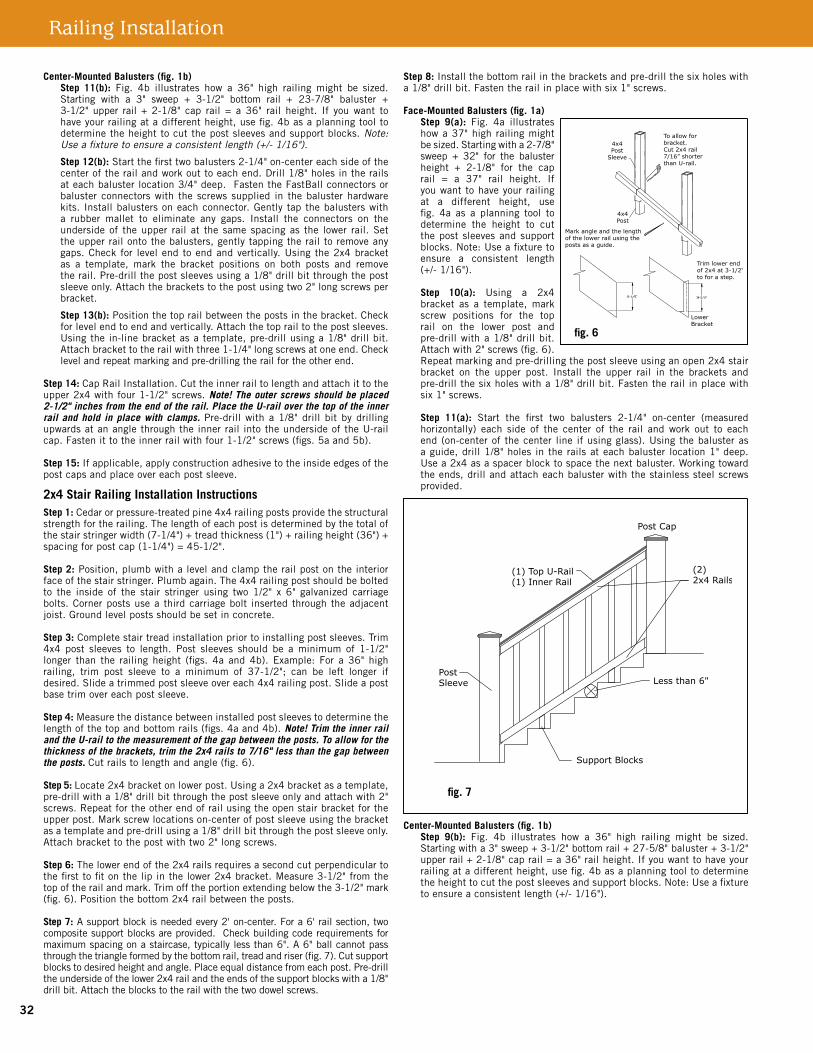
Railing Installation
Center-Mounted Balusters (fig. 1b)Step 11(b): Fig. 4b illustrates how a 36" high railing might be sized.Starting with a 3" sweep + 3-1/2" bottom rail + 23-7/8" baluster + 3-1/2"upper rail+2-1/8" cap rail = a 36" rail height. If youwant tohaveyourrailingatadifferentheight,usefig.4basaplanningtooltodeterminetheheighttocutthepostsleevesandsupportblocks.Note: Use a fixture to ensure a consistent length (+/- 1/16").
Step 12(b): Start the first two balusters 2-1/4" on-center each side of the centeroftherailandworkouttoeachend.Drill1/8"holesintherailsateachbalusterlocation3/4"deep.FastentheFastBallconnectorsorbaluster connectors with the screws supplied in the baluster hardware kits.Installbalustersoneachconnector.Gentlytapthebalusterswitha rubber mallet to eliminate any gaps. Install the connectors on theundersideof theupper rail at the samespacingas the lower rail.Settheupperrailontothebalusters,gentlytappingtherailtoremoveanygaps.Checkfor levelendtoendandvertically.Usingthe2x4bracketas a template, mark the bracket positions on both posts and removetherail.Pre-drillthepostsleevesusinga1/8"drillbitthroughthepostsleeveonly.Attachthebracketstothepostusingtwo2"longscrewsperbracket.
Step 13(b):Positionthetoprailbetweenthepostsinthebracket.Checkforlevelendtoendandvertically.Attachthetoprailtothepostsleeves.Usingthein-linebracketasatemplate,pre-drillusinga1/8"drillbit.Attachbrackettotherailwiththree1-1/4"longscrewsatoneend.Checklevelandrepeatmarkingandpre-drillingtherailfortheotherend.
Step 14:CapRailInstallation.Cuttheinnerrailtolengthandattachittotheupper2x4withfour1-1/2"screws.Note! The outer screws should be placed 2-1/2" inches from the end of the rail. Place the U-rail over the top of the inner rail and hold in place with clamps. Pre-drillwith a1/8"drill bit bydrillingupwards at an angle through the inner rail into the underside of the U-rail cap.Fastenittotheinnerrailwithfour1-1/2"screws(figs.5aand5b).
Step 15:Ifapplicable,applyconstructionadhesivetotheinsideedgesofthepostcapsandplaceovereachpostsleeve.
2x4 Stair Railing Installation InstructionsStep 1:Cedarorpressure-treatedpine4x4railingpostsprovidethestructuralstrengthfortherailing.Thelengthofeachpostisdeterminedbythetotalofthestairstringerwidth(7-1/4")+treadthickness(1")+railingheight(36")+spacingforpostcap(1-1/4")=45-1/2".
Step 2:Position,plumbwithalevelandclamptherailpostontheinteriorfaceofthestairstringer.Plumbagain.The4x4railingpostshouldbeboltedto the inside of the stair stringer using two 1/2" x 6" galvanized carriagebolts.Cornerpostsusea thirdcarriagebolt insertedthroughtheadjacentjoist.Groundlevelpostsshouldbesetinconcrete.
Step 3:Completestairtreadinstallationpriortoinstallingpostsleeves.Trim4x4 post sleeves to length. Post sleeves should be a minimum of 1-1/2"longer than the railingheight (figs.4a and4b).Example: For a36" highrailing, trim post sleeve to a minimum of 37-1/2"; can be left longer ifdesired.Slideatrimmedpostsleeveovereach4x4railingpost.Slideapostbasetrimovereachpostsleeve.
Step 4:Measurethedistancebetweeninstalledpostsleevestodeterminethelengthofthetopandbottomrails(figs.4aand4b).Note! Trim the inner rail and the U-rail to the measurement of the gap between the posts. To allow for the thickness of the brackets, trim the 2x4 rails to 7/16" less than the gap between the posts. Cutrailstolengthandangle(fig.6).
Step 5: Locate2x4bracketonlowerpost.Usinga2x4bracketasatemplate,pre-drillwitha1/8"drillbitthroughthepostsleeveonlyandattachwith2"screws.Repeatfortheotherendofrailusingtheopenstairbracketfortheupperpost.Markscrewlocationson-centerofpostsleeveusingthebracketasatemplateandpre-drillusinga1/8"drillbitthroughthepostsleeveonly.Attachbrackettothepostwithtwo2"longscrews.
Step 6:Thelowerendofthe2x4railsrequiresasecondcutperpendiculartothefirsttofitonthelipinthelower2x4bracket.Measure3-1/2"fromthetopoftherailandmark.Trimofftheportionextendingbelowthe3-1/2"mark(fig.6).Positionthebottom2x4railbetweentheposts.
Step 7:Asupportblockisneededevery2'on-center.Fora6'railsection,twocompositesupportblocksareprovided.Checkbuildingcoderequirementsformaximumspacingonastaircase,typicallylessthan6".A6"ballcannotpassthroughthetriangleformedbythebottomrail,treadandriser(fig.7).Cutsupportblockstodesiredheightandangle.Placeequaldistancefromeachpost.Pre-drilltheundersideofthelower2x4railandtheendsofthesupportblockswitha1/8"drillbit.Attachtheblockstotherailwiththetwodowelscrews.
Step 8: Install the bottom rail in the brackets and pre-drill the six holes with a1/8"drillbit.Fastentherailinplacewithsix1"screws.
Face-Mounted Balusters (fig. 1a)Step 9(a): Fig. 4a illustrateshowa37"highrailingmightbesized.Startingwitha2-7/8"sweep + 32" for the balusterheight + 2-1/8" for the caprail = a 37" rail height. Ifyouwanttohaveyourrailingat a different height, use fig. 4a as a planning tool todetermine the height to cut thepostsleevesandsupportblocks.Note:Useafixturetoensure a consistent length (+/-1/16").
Step 10(a): Using a 2x4 bracket as a template, mark screw positions for the top rail on the lower post and pre-drillwitha1/8"drillbit.Attachwith2"screws(fig.6).Repeatmarkingandpre-drillingthepostsleeveusinganopen2x4stairbracket on the upper post. Install the upper rail in the brackets andpre-drillthesixholeswitha1/8"drillbit.Fastentherailinplacewithsix1"screws.
Step 11(a): Start the first two balusters 2-1/4" on-center (measured horizontally) each side of the center of the rail and work out to eachend(on-centerofthecenter line ifusingglass).Usingthebalusterasaguide,drill1/8"holes intherailsateachbaluster location1"deep.Usea2x4asaspacerblocktospacethenextbaluster.Workingtowardthe ends, drill and attach each baluster with the stainless steel screws provided.
Center-Mounted Balusters (fig. 1b)Step 9(b): Fig. 4b illustrates how a 36" high railing might be sized.Startingwitha3"sweep+3-1/2"bottomrail+27-5/8"baluster+3-1/2"upperrail+2-1/8"caprail=a36"railheight.Ifyouwanttohaveyourrailingatadifferentheight,usefig.4basaplanningtooltodeterminetheheighttocutthepostsleevesandsupportblocks.Note:Useafixturetoensureaconsistentlength(+/-1/16").
LatitudesIntrepid™2x4RailingInstallationInstructions–PAGE3
fig. 6
fig. 7
32

Step 10(b): Start the first two balusters 2-3/4" on-center each side ofthecenteroftherail.Measureandmarkeachbalusterlocation5-1/2"on-centerouttoeachendoftherail.Drill1/8"holesintherailsateachbaluster location3/4" deep. Fasten the FastBall connectors or squarebaluster connectors with stair adaptors, using the screws supplied in the balusterhardwarekits. Installbalustersoneachconnector.Gently tapthebalusterswitharubbermallettoeliminateanygaps.Checkforlevelendtoend.Installthebalusterconnectorsontheundersideoftheupperrailatthesamespacingasthelowerrail.
Step 11(b):Positiontheupperrailontothebalusters,gentlytappingtherailtoremoveanygaps.Checkforlevelendtoendandvertically.Usingthe stair bracket as a template, mark the bracket positions on both posts andremovethe rail.Pre-drill thescrew locationsusinga1/8"drillbitthroughthepostsleeveonly.Attachthebracketstothepostusingtwo2"longscrewsperbracket.Refittheupperrailintothebracketsandontobalusters.Re-checkforlevelendtoendandvertically.Attachtheupperrailtothebracketwithsix1"longscrews.
Step 12:CuttheinnerrailandU-railtolengthandangle.Attachinnerrailto theupper2x4withfour1-1/2"screws.PlacetheU-railover thetopoftheinnerrail.Pre-drillwitha1/8"drillbitbydrillingupwardsatananglethroughtheinnerrailintotheundersideoftheU-railcap.Fastenittotheinnerrailwithfour1-1/2"screws.
Step 13:Applyconstructionadhesivetotheinsideedgesofthepostcapsandplaceovereachpostsleeve.
Compositedeckingandrailingisnotsuitableforstructuraluse.Itshouldnotbe used for primary load-bearing members such as posts, joists, beams orstringers.Thesamecommon-senseprecautionsshouldbetakenwhenhandlingcompositedeckingaswithwoodorotherbuildingmaterials.Dustmasksandeye protection devices are recommended to avoid possible irritation fromsawdust andchips.Gloveswill help toprotect thehands.Hands shouldbewashedafterdoingconstructionwork.
Thediagramsandinstructionsinthisbrochureareforillustrationpurposesonlyandarenotmeanttoreplacealicensedprofessional.Anyconstructionoruseoftheproductmustbeinaccordancewithalllocalzoningand/orbuildingcodes.Theconsumerassumesallrisksandliabilityassociatedwiththeconstructionoruseof thisproduct.Theconsumerorcontractorshouldtakeallnecessarystepstoensurethesafetyofeveryoneinvolvedintheproject,including,butnotlimited to,wearing the appropriate safety equipment. ExCEPT aS ConTaInED In ThE wRITTEn LIMITED waRRanTy, ThE waRRanToR DoES noT PRovIDE any oThER waRRanTy, EIThER ExPRESS oR IMPLIED, anD ShaLL noT BE LIaBLE FoR any DaMagES, InCLuDIng ConSEquEnTIaL DaMagES.
ManufacturedbyUFPVenturesII,Inc.,aUniversalForestProductsCompany
1801E.Lessard,PrairieduChien,WI53821877.463.8379
latitudesdeck.com
©2010 Universal Forest Products, Inc. All rights reserved. Latitudes is a registered trademark of Universal Forest Products, Inc. in the U.S. and other countries. Latitudes Intrepid is a trademark of Universal Consumer Products, Inc., in the U.S. The Architectural Testing Approved logo is registered trademark of Architectural Testing, Inc.
6053 2x4 ENG_5/10
Latitudes Intrepid™ 2x4 Railing Installation Instructions – PAGE 433

Secondary Handrail Guidelines and Installation
90° Inside CornerStep 1: Measure 2” less than the handrail height to determine inside corner bracket position. Mark post.Step 2: Align the top of the bracket mounting plate with the mark made in Step 1. Drill 5/32” pilot holes and attach to the post using the 1-1/2” screws provided.Step 3: Align the 90° inside corner so that it is centered evenly on the bracket, ensure it is level, and clamp into place. Drill 3/16” pilot holes and secure with 1” screws provided.Step 4: Slide aluminum joiners into each side of corner. Slide joiners into handrails and follow instructions for “Aluminum Joiner Kit.”
Secondary Handrail Guidelines and Installation
Prior to construction, check with your local regulatory agency for special code requirements in your area.
Start with an Inside Corner piece when applicable.
Guidelines: • Theheightofthesecondaryhandrailmustbeinstalledbetween
34”and38”abovethesurface,regardlessoftheheightoftheguard.
• Werecommendthathandrailsbedryfitpriortofinalinstallationto eliminatecuttingandfasteningerrors.
• IMPORTANT:Thesecondaryhandrailmustbeattachedtoastructural support.Wheninstallingmountingbracketsonpostsleeves,ensure thehardwareattachestothestructuralsupport.
• Formaximumstrength,bracketsshouldbeusedateverypostand everyjoint,orascloselyaspossibletothejoint.
• Anadhesivemaybeappliedtofurtherreinforceconstruction.
• Handrailsmustbesupportedevery6’on-centerbyamountingbracket.
Handrail with Aluminum InsertStep 1: Dry fit handrails to determine proper lengths prior to cutting rails.Step 2: Measure and cut rails to proper lengths for all runs.Step 3: Install to handrail component, following instructions for the components.
Tools Required• Drill• Miter/CircularSaw• QuickClamps• PVCCleaner
• Pencil• TapeMeasure• Level
Hand Rail Parts.ai
End Cap 90˚ Outside Corner
180˚ Post Return
Handicap Loop
Straight Aluminum Wall Mount90˚ Post Return
Aluminum Bracket (Line Post Mounting Bracket)
Inside Corner Mounting Bracket
Handrail with Aluminum InsertAluminum Joiner KitAdjustable Joiner
32˚ Stair Elbow34˚ Stair Elbow36˚ Stair Elbow
5˚ Handicap Elbow90˚ Inside Corner13.5” Wall Return
Handrail Componentsd
Adjustable JoinerStep 1: Measure the angle needed. Adjoin the two joiner halves together by inserting the bolt. Place the joiner halves at the desired angle, and tighten bolt to set.Step 2: Cut handrails at ½ the desired angle. Slide handrails onto adjustable joiner.Step 3: Drill 3/16” pilot holes and fasten handrails together using 3/4” screws.
1
22
3
AdjustableJoiner2.ai
Aluminum Joiner KitStep 1: Use aluminum joiner to fasten handrail components at straight joints.Step 2: Slide joiner an equal distance into both components. Drill 3/16” pilot holes and fasten using 3/4” screws provided.Note: All joiners should be supported by an aluminum bracket as closely as possible to the joint.
12
2
AluminumJoinerKit2.ai
3
3
4
1
2
2"
AluminumBracket.ai
Aluminum Bracket (Line Post Mounting Bracket)Step 1: Measure 2” less than the handrail height to determine bracket position. Mark surface.Step 2: Align the top of the bracket mounting plate with the mark made in Step 1. Drill 5/32” pilot holes and attach to the desired surface using the 1-1/2” screws provided.Step 3: Clamp handrail to bracket at appropriate location to secure in place.Step 4: Drill 3/16” pilot holes and attach handrail using the 1” screws provided.
1
2 2
3
44
90°InsideCorner3.ai
2"
34

Stair ElbowsStep 1: Attach aluminum bracket to post, following instructions under “Aluminum Bracket”.Step 2: Choose proper degree of stair elbow. Slide aluminum joiners into each side of the stair elbow. Slide joiners into handrails, and follow instructions for “Aluminum Joiner Kit”.Step 3: Attach elbow to bracket, drilling 3/16” pilot holes and securing with the 1” screws provided.
3
4
1
2
22"
StairElbow.ai
Handicap Loop Step 1: Position handicap loop in desired location. Mark and cut loop as necessary.Step 2: Attach handicap loop to handrail system using aluminum joiner (for level installation) or adjustable joiner (for angled installation).Step 3: Attach top and bottom aluminum brackets to surface at desired locations, following instructions under “Aluminum Bracket”.Step 4: Attach the handicap loop to the aluminum brackets by drilling 3/16” pilot holes and securing with the 1” screws provided.Step 5: Attach end cap to unfinished end of loop.Note: The alternate installation method uses the 90° post return for the lower portion of the handicap loop, terminating into the end post.
4
1
2
2"
3
3
4
5 2"
HandicapLoop.ai
90° Post ReturnStep 1: Slide 90° post return into handrail. Step 2: Drill 5/32” pilot holes into the desired surface and attach post return using 1-1/2” screws provided.Step 3: Drill 3/16” pilot holes into handrail and attach using 3/4” screws provided.
Straight Aluminum Wall MountStep 1: Slide aluminum wall
mount into handrail.
Step 2: Drill 5/32” pilot holes
into desired surface and attach
wall mount using 1-1/2”
screws provided.
Step 3: Drill 3/16” pilot holes
into handrail and attach using
3/4” screws provided.
1
2
StraightWall-Mount2.ai
3
90° Outside CornerStep 1: Attach two aluminum brackets to adjacent corners of post, following instructions from “Aluminum Bracket”.Step 2: Dry fit the two handrails to be joined. The handrails should extend far enough to allow for final cutting. Place outside corner in line with each handrail. Mark handrails and cut as necessary.Step 3: Slide aluminum joiners into both sides of outside corner. Slide joiners into handrails, and follow instructions for “Aluminum Joiner Kit”.Step 4: Attach handrails to brackets, following instructions from “Handrail with Aluminum Insert”.
1
2 2
3 4 3
4
90°OutsideCorner.ai 180° Post ReturnStep 1: Position post return in desired location. Mark and cut as necessary.Step 2: Attach post return to handrail system using aluminum joiner.Step 3: Attach aluminum bracket to the desired surface, following instructions from “Aluminum Bracket.”Step 4: Attach post return to aluminum bracket, drilling 3/16” pilot holes and securing with 3/4” screws provided.
4
1
22"
3
180PostReturn.ai
13.5” Wall ReturnStep 1: Position 13.5” wall return in desired location. Mark and cut as necessary.Step 2: Attach wall return to handrail system using aluminum joiner or adjustable joiner. Step 3: Attach the handrail to the aluminum bracket.
The diagrams and instructions in this brochure are for illustration purposes only and are not meant to replace a licensed professional. Any construction or use of the product must be in accordance with all local zoning and/or building codes. The consumer assumes all risks and liability associated with the construction or use of this product. The consumer or contractor should take all necessary steps to ensure the safety of everyone involved in the project, including, but not limited to, wearing the appropriate safety equipment. Seller makes no warranty for this product, either express or implied. Seller expressly disclaims any and all liability for damages arising out of the use or ownership of the product, including disclaiming incidental and consequential damages, unless otherwise required by state law.
This handrail configuration has been tested and meets the requirements of 2009 IBC/IRC.
6' O.C. Structural Support
Structural Support
Aluminum Bracket with Screws Provided
Aluminum Bracket with Screws Provided
Handrail with Aluminum Insert
Handrail Asm.ai
(2) #14 x 1" Screws Provided
(2) #14 x 1" Screws Provided
UniversalConsumerProducts,Inc.3851 Revere StreetDenver, CO 80239
877-436-8379
www.ufpi.com
1
2
3
90°Post Return2.ai
35

Important safety information pertaining to risk of fire or injury to person.
•Donotinstallwithin10feet(3m)ofapool,spaorfountain.•Donotlookdirectlyintothelight.•Forusewith12-volt,low-voltageoutdoorlandscapelightingsystemonly.•Therearenoserviceablepartsinsidethepowersupplyunit.Donotdisassemble.•PlugthepowersupplyunitdirectlyintoaGFCIreceptaclethatismarked“wetlocation.”•Thetransformercansupportamaximumof24individuallights.
Pleasenote:Thelightsystemmustbeinstalledinaccordancewithalllocalcodesandordinances.Ifyouareexperiencingproblems,contactaqualifiedelectrician.
Step 1 | Find a location for the transformer and photo sensor
•Outdooruse,weather-resistant.•Donotinstallthephotosensorbehindshrubs.Thiswillaffectthephotosensor.•Thephotosensorwillnotoperateproperlyifinstalledtooclosetoalightsource.
Step 2 | Mount the photo sensor
Mountthephotosensorwiththeincludedscrewonawallwithinonefoot(30cm)oftheelectricaloutletwherethetransformerwillbeconnected(Figure1).
* Alternate photo sensor installation: If there is no area within 1 foot (30.5cm) of the transformer to install the photosensor, it is possible to install the extension wire directly to the transformer and to install the photo sensor between the extension wire and the first light.
Step 3 | Position lights and run wire
•Thewireshouldrunfromthephotosensortoeachlight,withoutbeingcut.Donotrunthewirewithin10feet(3m)ofapool,spaorfountain.
•Loosewireshouldbetiedupandkeptclearofwalkingpathsandawayfromchildrenoranimals.
•Connecttheextensionwireandalllightfixturesend-to-end,makingonelongwireconnection.Thisisthedistanceavailablewhenpositioningyourlights.
Please note: Additional light and wire add-ons are available in packs of two. Additional extension wire is available in 16.4’ length. These add-ons are compatible with and follow the same installation steps as the lights and wire in the original kit.
•Mostcommonlightplacementsareonstepriserstoilluminatestairs,orflatonthedecksurfacetodelineateextremitiesandilluminaterailingsorwalls.
•Positionthelightfixtures,makingsurethattheextensionwirewillreachthephotosensor.Oncetheyareproperlypositioned,drilloutholesusingtheincluded1”drillbit.
Important note: Please make sure that you have properly calculated your distances and are confident of the positioning of the lights before drilling holes.
•Disconnectthelightsfromeachotherandinserteachfixtureintoitscorrespondingholebyfeedingthetwo(2)wiresfirstthenpressingthefixturefirmlyintotheholesothatitfitstightlyagainstthesurface.Repeatthisstepforalleight(8)lights.
•Connectthemaleendoftheextensionwiretothe“OUT”connectionofthephotosensorandthefemaleendtothefirstfixture.
•Connectthefemaleendoftheextensionwiretothefirstlightfixtureandeachfixturetothenext.
Step 4 | Connect the photo sensor and the transformer
•Connectthephotosensortothetransformer.•Plugthetransformerintotheelectricalreceptacle.
How to test the system
•Totestthelightsduringdaytime,coverthephotosensorwithblacktape.•Thiscomponentreactstolightconditions.ItautomaticallyturnsONthelightfixturesat
duskandturnsthemOFFatdawn.Itshouldnotbeexposedtoanyartificiallightsources.
Trouble shooting
•Mostproblemsliewithinthefixture’sconnectionorLEDs.•Checktheconnectionandmakesurethemaleandfemaleconnectorsarepressing
firmlytogether,andsecurewiththescrewnut.•Tocheckalightfixture,exchangeitwithanotherfixturethatisworking.
Maintenance
•Toclean,wipewithasoft,dampcloth.•Replacementpartsmaybeorderedbyusingthefixturemodelnumberandthepart’sname.
Extensionwire
Transformer
LEDdecklight Photosensor
Drillbit
One Recessed Lighting Kit contains
•Eight(8)LEDdecklights •One(1)photosensor•One(1)transformer •One(1)drillbit•One(1)extensionwire
Transformer Photosensor Connector Lightfixture
Extensionwire
Illustration of fixture is for example only.
Figure 1 Figure 2
Figure 3
OUTDOORTRANSFORMER
E323535
Recessed Lighting Kit Installation Instructions
36
Get the free mobile app at http://gettag.mobi
Scan code to learn how to install recessed lighting.
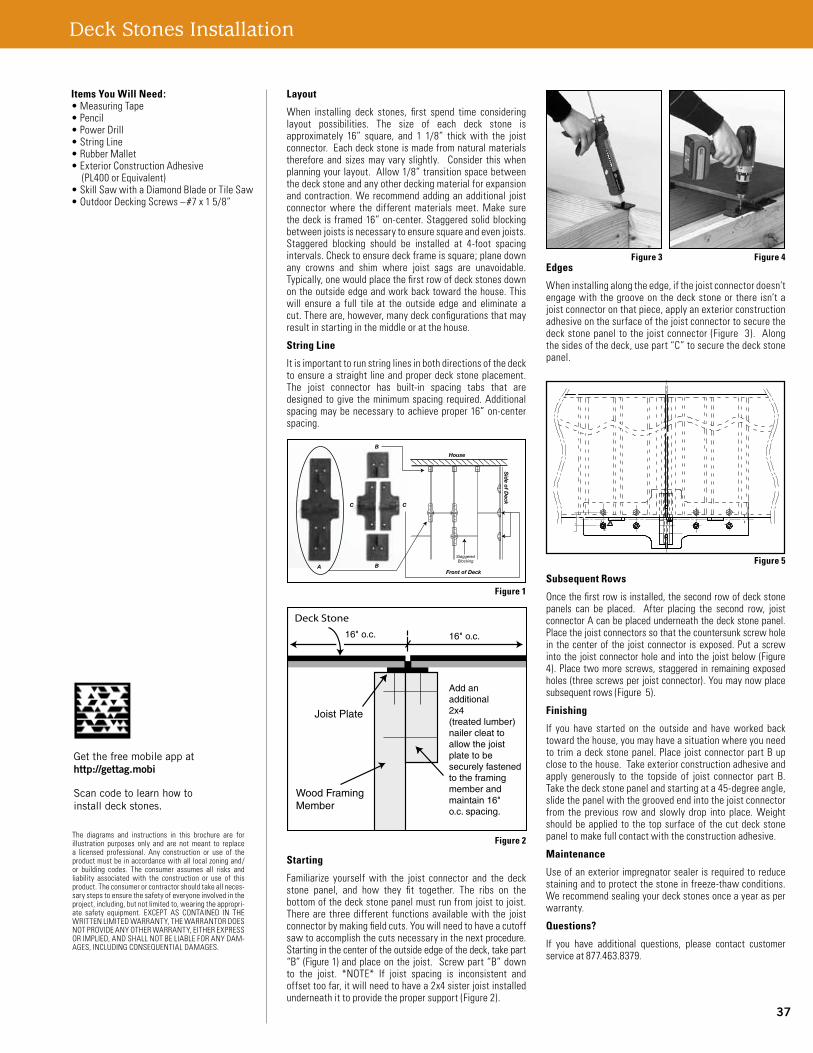
Layout
When installing deck stones, first spend time consideringlayout possibilities. The size of each deck stone isapproximately 16” square, and 1 1/8” thick with the joistconnector.Eachdeckstoneismadefromnaturalmaterialstherefore and sizes may vary slightly. Consider this whenplanningyourlayout.Allow1/8”transitionspacebetweenthedeckstoneandanyotherdeckingmaterialforexpansionand contraction.We recommendaddinganadditional joistconnector where the different materials meet. Make surethedeck is framed16”on-center.Staggeredsolidblockingbetweenjoistsisnecessarytoensuresquareandevenjoists.Staggered blocking should be installed at 4-foot spacingintervals.Checktoensuredeckframeissquare;planedownany crowns and shim where joist sags are unavoidable.Typically,onewouldplacethefirstrowofdeckstonesdownontheoutsideedgeandworkbacktowardthehouse.Thiswill ensure a full tile at the outside edge and eliminate acut.Thereare,however,manydeckconfigurationsthatmayresultinstartinginthemiddleoratthehouse.
String Line
Itisimportanttorunstringlinesinbothdirectionsofthedecktoensureastraight lineandproperdeckstoneplacement.The joist connector has built-in spacing tabs that aredesigned togive theminimumspacing required.Additionalspacingmaybenecessary toachieveproper16”on-centerspacing.
Starting
Familiarize yourself with the joist connector and the deckstone panel, and how they fit together. The ribs on thebottomofthedeckstonepanelmustrunfromjoisttojoist.Thereare threedifferent functionsavailable with the joistconnectorbymakingfieldcuts.Youwillneedtohaveacutoffsawtoaccomplishthecutsnecessaryinthenextprocedure.Startinginthecenteroftheoutsideedgeofthedeck,takepart“B”(Figure1)andplaceonthe joist. Screwpart“B”downto the joist. *NOTE* If joist spacing is inconsistent andoffsettoofar,itwillneedtohavea2x4sisterjoistinstalledunderneathittoprovidethepropersupport(Figure2).
Edges
Wheninstallingalongtheedge,ifthejoistconnectordoesn’tengagewith thegrooveon thedeckstoneor there isn’tajoistconnectoronthatpiece,applyanexteriorconstructionadhesiveonthesurfaceofthejoistconnectortosecurethedeckstonepanel to the joistconnector (Figure 3). Alongthesidesofthedeck,usepart“C”tosecurethedeckstonepanel.
Subsequent Rows
Oncethefirstrowisinstalled,thesecondrowofdeckstonepanels can be placed. After placing the second row, joistconnectorAcanbeplacedunderneaththedeckstonepanel.Placethejoistconnectorssothatthecountersunkscrewholein the centerof the joist connector isexposed. Puta screwintothe joistconnectorholeand intothe joistbelow(Figure4).Place twomorescrews,staggered in remainingexposedholes(threescrewsperjoistconnector).Youmaynowplacesubsequentrows(Figure5).
Finishing
If you have started on the outside and have worked backtowardthehouse,youmayhaveasituationwhereyouneedto trimadeckstonepanel.Place joistconnectorpartBupclosetothehouse.Takeexteriorconstructionadhesiveandapply generously to the topside of joist connector part B.Takethedeckstonepanelandstartingata45-degreeangle,slidethepanelwiththegroovedendintothejoistconnectorfrom the previous row and slowly drop into place. Weightshouldbeapplied to the topsurfaceof thecutdeck stonepaneltomakefullcontactwiththeconstructionadhesive.
Maintenance
Useofanexterior impregnatorsealer isrequiredtoreducestainingandtoprotectthestoneinfreeze-thawconditions.Werecommendsealingyourdeckstonesonceayearasperwarranty.
Questions?
If you have additional questions, please contact customerserviceat877.463.8379.
A B
B
C C
House
Front of Deck
Sid
e of Deck
StaggeredBlocking
Deck Stone
16" o.c.
Joist Plate
Wood FramingMember
Add anadditional2x4 (treated lumber)nailer cleat toallow the joist plate to be securely fastened to the framing member and maintain 16"o.c. spacing.
16" o.c.
Items You Will Need:•MeasuringTape•Pencil•PowerDrill•StringLine•RubberMallet•ExteriorConstructionAdhesive (PL400orEquivalent)•SkillSawwithaDiamondBladeorTileSaw•OutdoorDeckingScrews–#7x15/8”
The diagrams and instructions in this brochure are forillustration purposes only and are not meant to replacea licensed professional. Any construction or use of theproductmustbeinaccordancewithall localzoningand/or building codes. The consumer assumes all risks andliability associated with the construction or use of thisproduct.Theconsumerorcontractorshouldtakeallneces-sarystepstoensurethesafetyofeveryoneinvolvedintheproject,including,butnotlimitedto,wearingtheappropri-ate safety equipment. ExCEPT AS CONTAINED IN ThEWRITTENLIMITEDWARRANTY,ThEWARRANTORDOESNOTPROvIDEANYOThERWARRANTY,EIThERExPRESSORIMPLIED,ANDShALLNOTBELIABLEFORANYDAM-AGES,INCLUDINGCONSEqUENTIALDAMAGES.
Figure 1
Figure 2
Figure 4
Figure 5
Figure 3
Deck Stones Installation
37
Get the free mobile app at http://gettag.mobi
Scan code to learn how to install deck stones.

Latitudes Capricorn and Captiva 25-year Stain and Fade Limited Warranty
ELIGIBILITyUFPVenturesII,Inc.(the“Warrantor”)ispleasedtoextendthis Warranty to you, the original end user of the product. This Warranty is valid for Latitudes Capricorn® and Captiva™
products used in a standard residential application and may not be assigned or transferred by you.
25-yEAR LIMITED WARRANTy – STAIN RESISTANCEWarrantor will, at Warrantor’s sole discretion, replace or refund the appropriate prorated portion of the purchase price as set forth below for any Latitudes Capricorn and Captiva product used in a residential deck application that exhibits permanent staining in the first 25 years from the date of purchase when exposed to food and beverage spills including wine, tea, coffee, fruit punch, sodas, catsup, salad oils, barbeque sauces, mustard and other food or beverage related items that would typically be present on a residential deck. Any such spill should be removed from the decking material with water and mild household cleaners within forty-eight (48) hours of exposure to the surface. Staining as a result of spilled abrasive compounds of acidic or basic pH, strong solvents, oil-based paints or stains, metallic rust and other abnormal items not commonly used on a residential deck are not covered under this warranty.
25-yEAR LIMITED WARRANTy – FADE RESISTANCEWarrantor will, at Warrantor’s sole discretion, replace or refund the appropriate prorated portion of the purchase price as set forth below for any Latitudes Capricorn and Captiva product used in a residential deck application that exhibits “Excessive Color Fade” within the first 25 years from the date of purchase. Excessive Color Fade is defined as a change in color greater than five (5) Delta E (CIE) when cal-culated according to ASTM D2244 for all non-variegated color sur-faces. Excessive Color Fade for variegated color surfaces is defined as an unreasonable amount of color change in excess of “Normal Weathering.”
LIMITATIONS ON WARRANTyStain Limitations: The Latitudes Capricorn and Captiva products are not stain-proof. Care must be taken to remove all food, beverage and other spilled materials with water and a mild household cleaner within forty-eight (48) hours of exposure. Stains resulting from spilled abrasive compounds of acidic or basic pH, strong solvents, oil-based paints or stains, metallic rust and other abnormal items not common-ly used on a residential deck are excluded from coverage under this warranty; excluded stains include but are not limited to pet or human bodily fluids such as blood, vomit, urine or feces, and fungicides, bactericides, biocides and chemical-based plant food. Mold and mil-dew can settle and grow on any outdoor surface and, if not properly cleaned, can stain that surface. Staining associated with mold or mildew that is not properly cleaned within one week of first appear-ance is not covered under this warranty. If stains persist, you will be required to produce documentation that you attempted to have the deck professionally cleaned at least one time prior to making a claim under this warranty.
Fade Limitations: No decking material is fade-proof when exposed to sunlight and other common atmospheric conditions. Normal Weathering is to be expected over the life of the product and is not covered under this warranty. Normal Weathering is defined as expo-sure to sunlight and extremes of weather and atmosphere that will cause any colored surface to gradually fade, chalk, or accumulate dirt or stains.
This warranty does not cover costs for installation, removal or rein-stallation. Warrantor shall not be liable for any incidental or conse-quential damages arising out of the use or ownership of this product.
Some states do not allow limitations on how long an implied warranty lasts and/or do not allow the exclusion of incidental or consequential damages, so the above limitations and exclusions may not apply to you. This Warranty gives you specific legal rights, and you may also have other rights, which vary from state to state.
This warranty does not cover any product that: •Isdamagedbyphysicalabuse,actsofGod,actsofwar,orother chemical or biological factors.•Hasnotbeeninstalledinaccordancewiththemanufacturer’s installation guidelines and local building codes.•Hasbeenabused,placedunderorsubjectedtoabnormalresidential use conditions or has surface damage or surface punctures.•Hasbeenpainted,coated,used,modifiedorotherwisetreatedinany manner other than as intended by Warrantor.•Hasbeendirectlyorindirectlyexposedtoextremeheat(inexcessof 250 degrees Fahrenheit).
Failure to follow any restrictions or warnings supplied with the product shall make the Warranty null and void and of no further effect. Warrantor reserves the right to investigate any claim and to inspect the materials for which a claim is made. Any construction or use of this product must be in accordance with all local zoning and/or building codes. The Consumer assumes all risk and liability associated with the construction or use of this product. The Consumer or contractor should take all necessary steps to ensure the safety of everyone involved in the project, including, but not limited to, wearing the appropriate safety equipment.
CLAIM PROCEDURETo make a claim under this Warranty, the original owner must, within 30 days of actual or constructive notice of damage covered by the Warranty, do the following:
(1)Preparealetterthatincludesthefollowinginformation:•Alistofthenumberofpiecesandsizeofeachpieceforwhichtheclaim is made.•ProofofPurchaseoftheproduct,asshownontheoriginalinvoiceorreceipt.•ProofofWarranty,asevidencedbytheoriginalUPCfromtheproductora copy of the mark on the product.•ProofofCleaning,asevidencedbyaninvoiceorreceiptfromaprofessional cleaning service.
(2) Mail the above information to: UFPVenturesII,Inc. Warranty Information 2801 East Beltline NE Grand Rapids, Michigan 49525
PRORATEDREFUNDSCHEDULEYearssincepurchasePercentpurchasepricecoveredYears 1 - 6 100% Years 7 - 10 80% Years 11 - 14 60% Years 15 - 18 40% Years 19 - 21 20% Years 22 - 25 10%
THERE ARE NO OTHER WARRANTIES WHICH EXTEND BEYOND THEDESCRIPTIONONTHEFACEHEREOF.WARRANTORDOESNOTMAKEANYIMPLIEDWARRANTYOFMERCHANTABILITYORFITNESSOFTHEPRODUCTFORAPARTICULARPURPOSE.
38

Capricorn arabica decking with riverstone granite deck stones 39

Deck Technologies, Inc. warrants its products to be free from defects in material and workmanship when delivered to its customers. The composite decking elements in the product are warranted against rot, decay and termites for a period of twenty (20) years and against all other deficiencies for ten (10) years from the date of purchase. The granite stone components in the product are warranted against delamination for five (5) years, and all other stone components are warranted for two (2) years from the date of purchase. This warranty is predicated on the condition that the customer applies an appropriate sealer material on the StoneDeck panels, in accordance with the man-ufacturer’s specified recommendations, in order to protect the stone from the effects of weather- and/or chemical-related deterioration.
Deck Technologies, Inc. further warrants that its products conform to the specifications published in its current literature. If a Deck Technologies, Inc. product is defective or does not meet the pub-lished specifications, and the customer gives written notice to Deck Technologies, Inc. before installing the product, Deck Technologies, Inc. will replace the product without charge to its customer or refund thepurchaseprice,atDeckTechnologies,Inc.’selection.PursuanttoDeck Technologies, Inc.’s directions, such customers shall return the applicable product to Deck Technologies, Inc. or destroy the defective product if so directed. Replacing the product or obtaining a refund are the buyer’s sole remedy for a warranty issue. Deck Technologies, Inc. will not be liable for any consequential damage attributed to a defec-tive product. Neither Deck Technologies, Inc. or any of its distributors shall, however, have any obligation to install such replacement product.
This warranty is given in lieu of all other warranties, express or implied, oral or written, and Deck Technologies, Inc. hereby EXPRESSLYDISCLAIMSALLOTHERWARRANTIES,INCLUDINGTHEIMPLIEDWARRANTYOFMERCHANTABILITYANDTHEIMPLIEDWARRANTYOFFITNESSFORAPARTICULARPURPOSE.Thereareno other warranties which extend beyond this description hereof.
To the best of our knowledge, the information contained in Deck Technologies, Inc.’s product literature is accurate. However, Deck Technologies, Inc. cannot assume any liability whatsoever for the accuracy or completeness thereof. Final determination of the suitability of any information or material for the use contemplated, or its manner of use shall be the sole responsibility of the user.
This warranty shall not apply to any Deck Technologies, Inc. product that is damaged or defective or fails to meet the warranty standard due to the manner in which it was installed; any chemicals coming in contact with the product; the design, engineering or permit approval of the structure in which the product is used; excessive or unforeseen site conditions; manufacturing defects; weather; construction; dropping of objects; equipment utilized; and other variables or conditions affecting results that are beyond Deck Technologies, Inc.’s control.
Deck Technologies, Inc.’s specifications are subject to change without notice.
All warranty information should be sent to: Deck Technologies, Inc. P.O.Box25225 Woodbury, MN 5512
Deck Stones Warranty
40

Latitudes® Decking and Railing 25-year Limited Structural Warranty
ELIGIBILITyUFPVenturesII,Inc.(the“Warrantor”),ispleasedtoextendthisWarranty to you, the original consumer of the Latitudes product. This Warranty is valid for Latitudes Decking and Composite Railing material used in standard residential dwellings and may not be assigned or transferred by you.
25-yEAR LIMITED WARRANTyWarrantor, at its option, will refund a percentage of the purchase price or replace any Latitudes Decking or Composite Railing product used in a decking or railing application that splinters, corrodes or becomes structurally unfit due to rot, split, warp, cupping, checks, or damage caused by termites or fungal decay within 25 years of the date of purchase.
This Warranty does not cover costs of installation, removal or reinstallation. This Warranty does not cover staining, color variations or fading. Warrantor’s sole obligation is limited to replacement of the Latitudes product, and Warrantor shall have no further liability or obligation except as expressly stated herein. The Warrantor may elect to refund the percentageoftheoriginalpurchasepricelistedontheProratedWarrantySchedule in lieu of replacing the product.
Limitations on WarrantyThe Warranty does not apply to any product that:•Isdamagedbyphysicalabuse,actsofGod,
acts of war, or other chemical or biological factors.• HasnotbeeninstalledinaccordancewithWarrantor’s
installation guidelines and local building codes.• Hasbeenabused,orplacedunderorsubjected
to abnormal residential use conditions.• Hasbeenused,modifiedorotherwisetreated
in any manner other than as intended by Warrantor.•Hasbeenstoredimproperlypriortoinstallation,
resulting in excess exposure to moisture.•Hasbeensubjectedtowelding,bending,drilling,cuttingorother
fabrication not called for in Warrantor’s installation guidelines.•Has been exposed to a corrosive environment including
the use of adhesive tapes, sealants or mastics in direct contact with the coated product.
•Isdamagedbycontinuousexposuretosaltwaterconditions when installed within one (1) mile of any coastal saltwater.
Customers living within 1,000 feet of the ocean should wash and wipe down their baluster two times a year and keep a record of each cleaning.
Failure to follow any restrictions or warnings supplied with the product shall make this Warranty null and void and of no further effect. Warrantor reserves the right to investigate any claim and to inspect the materials for which the claim is made. Any construction or use of product must be in accordance with local zoning and/or building codes. The Consumer assumes all risk and liability associated with the construction or use of this product. The Consumer or contractor should take all necessary steps to ensure the safety of everyone involved in the project, including, but not limited to, wearing the appropriate safety equipment.
Some states do not allow limitations on how long an implied warranty lasts and/or do not allow the exclusion of incidental or consequential damages, so the limitations and exclusions herein may not apply to you. This Warranty gives you specific legal rights, and you may also have other rights which vary from state to state. WARRANTOR SHALL NOT BE LIABLE FOR ANY INCIDENTAL OR CONSEQUENTIAL DAMAGES ARISINGOUTOFTHEUSEOROWNERSHIPOFTHISPRODUCT.
CLAIM PROCEDURETo make a claim under this Warranty, the Consumer must, within ninety (90) days of actual or constructive notice of damage covered by this Warranty, do the following:
(1)Preparealetterthatincludesthefollowinginformation:•Alistofthenumberofpiecesandsizeofeachpiece for which the claim is made.•ProofofPurchaseoftheproduct,asshownonthe original invoice or receipt.•ProofofWarranty,asevidencedbytheoriginalUPC or product tag, or a copy of the mark on the product.
(2) Mail the above information to:UFPVenturesII,Inc. Warranty Information 2801 East Beltline NE Grand Rapids, Michigan 49525
Prorated Warranty Schedule YearsSincePurchase PriceCovered Years 1 - 6 100% Years 7 - 10 80% Years 11 - 14 60% Years 15 - 18 40% Years 19 - 21 20% Years 22 - 25 10%
WARRANTOR DOES NOT MAKE ANy IMPLIED WARRANTy OF MERCHANTABILITy OR FITNESS OF THE PRODUCT FOR A PARTICULAR PURPOSE. THERE ARE NO OTHER WARRANTIES WHICH EXTEND BEyOND THE DESCRIPTION IN THE FACE HEREOF.
41

42
ELIGIBILITyUFPVenturesII,Inc.(the“Warrantor”),ispleasedtoextendthisWarranty toyou,theoriginalconsumer,oftheLatitudesProduct.ThisWarrantyisvalid for Latitudes Ornamental Aluminum and Glass balusters used in standard residential applications and may not be assigned or transferred by you.
25-yEAR LIMITED WARRANTyWarrantor, at its sole option, will replace or refund a prorated portion of the purchase price for any aluminum baluster used in a decking/railing application where the coated surface chips, cracks, checks, chalks or peels for a period of 25 years from date of purchase. Warrantor will also, at its sole option, replace or refund a prorated portion of the purchase price for any manufacturing defects in the tempered glass material or aluminumextrusionforProductusedinadecking/railingapplication.
This Warranty does not cover costs of installation, removal or reinstallation. Warrantor’s sole obligation is limited to a prorated refund or replacement oftheProduct,andWarrantorshallhavenofurtherliabilityorobligationexcept as expressly stated herein. If a claim is made under this Warranty on a product that is no longer available, Warrantor reserves the right to provide a similar product of equivalent quality and value.
Limitations on WarrantyThe Warranty does not apply to any product which: •Isdamagedbyphysicalabuse,actsofGod,acts
of war, or other chemical or biological factors. •HasnotbeeninstalledinaccordancewithWarrantor’s
installation guidelines and local building codes. •Hasbeenabused,placedunderorsubjected
to abnormal residential use conditions. •Hasbeenused,modified,orotherwisetreated
in any manner other than as intended by Warrantor.
Aluminum BalusterWarrantor, at its sole option, will replace or refund a prorated portion of the purchase price for any powder coated aluminum tubes used in a decking/railing application where the coated surface chips, cracks, checks, chalks or peels for a period of 25 years from date of purchase. Warrantor will also, at its sole option, replace or refund a prorated portion of the purchase price for any manufacturing defects in the aluminum extrusionforProductusedinadecking/railingapplication.
This Warranty does not cover costs of installation, removal or reinstallation. Warrantor’s sole obligation is limited to a prorated refund or replacement oftheProduct,andWarrantorshallhavenofurtherliabilityorobligationexcept as expressly stated herein. If a claim is made under this Warranty on a product that is no longer available, Warrantor reserves the right to provide a similar product of equivalent quality and value.
Limitations on Warranty The Warranty does not apply to any product that:•Isdamagedbyphysicalabuse,actsofGod,
acts of war, or other chemical or biological factors.•HasnotbeeninstalledinaccordancewithWarrantor’s
installation guidelines and local building codes.•Hasbeenabused,orplacedunderorsubjected
to abnormal residential use conditions.•Hasbeenused,modifiedorotherwisetreated
in any manner other than as intended by Warrantor.•Hasbeenstoredimproperlypriortoinstallation,
resulting in excess exposure to moisture.•Hasbeensubjectedtowelding,bending,drilling,cuttingorother
fabrication not called for in Warrantor’s installation guidelines.
Latitudes® Ornamental Baluster 25-year Limited Warranty
•Hasbeenexposedtoacorrosiveenvironmentincludingtheuse of adhesive tapes, sealants or mastics in direct contact with the coated product.
•Isdamagedbycontinuousexposuretosaltwaterconditions when installed within one (1) mile of any coastal saltwater.
Customers living within 1,000 feet of the ocean should wash and wipe down their baluster two times a year and keep a record of each cleaning.
Prorated Warranty Schedule YearsSincePurchase PriceCovered Years 1 - 6 100% Years 7 - 10 80% Years 11 - 14 60% Years 15 - 18 40% Years 19 - 21 20% Years 22 - 25 10%
Failure to follow any restrictions or warnings supplied with the product shall make this Warranty null and void and of no further effect. Warrantor reserves the right to investigate any claim and to inspect the materials for which the claim is made. Any construction or use of product must be in accordance with local zoning and/or building codes. The Consumer assumes all risk and liability associated with the construction or use of this product. The Consumer or contractor should take all necessary steps to ensure the safety of everyone involved in the project, including, but not limited to, wearing the appropriate safety equipment.
Some states do not allow limitations on how long an implied warranty lasts and/or do not allow the exclusion of incidental or consequential dam-ages, so the limitations and exclusions herein may not apply to you. This Warranty gives you specific legal rights, and you may also have other rights which vary from state to state. WARRANTOR SHALL NOT BE LIABLE FOR ANY INCIDENTAL OR CONSEQUENTIAL DAMAGES ARISINGOUTOFTHEUSEOROWNERSHIPOFTHISPRODUCT.
CLAIM PROCEDURETo make a claim under this Warranty, the Consumer must, within ninety (90) days of actual or constructive notice of damage covered by this Warranty, do the following:
(1)Preparealetterthatincludesthefollowinginformation:•Alistofthenumberofpiecesandsize
of each piece for which the claim is made.•ProofofPurchaseoftheproduct,as
shown on the original invoice or receipt.•ProofofWarranty,asevidencedbytheoriginal
UPCorend-tagfromtheproduct,oracopy of the mark on the product.
(2) Mail the above information to:UFPVenturesII,Inc.Warranty Information 2801 East Beltline NE Grand Rapids, Michigan 49525
WARRANTOR DOES NOT MAKE ANy IMPLIED WARRANTy OF MERCHANTABILITy OR FITNESS OF THE PRODUCT FOR A PARTICULAR PURPOSE. THERE ARE NO OTHER WARRANTIES WHICH EXTEND BEyOND THE DESCRIPTION IN THE FACE HEREOF.

43
Latitudes® Marine Decking 10-Year Limited Commercial Warranty
ELIGIBILITyUFPVenturesII,Inc.(the“Warrantor”),ispleasedtoextendthisWarrantytoyou,theoriginalowneroftheresultingstructure using Latitudes®MarineBoardDecking(the“Product”).ThisWarrantyisvalidforLatitudesMarineBoardDecking material used in standard residential and commercial applications and may not be assigned or transferred by you.
10-yEAR LIMITED WARRANTyWarrantor, at its option, will replace or refund the purchase price for Latitudes Marine Board Decking used in a decking application that splinters, corrodes or becomes structurally unfit due to rot, split, warp, cupping, checks, or damage caused by termites or fungal decay within 10 years of the date of purchase.
This Warranty does not cover costs of installation, removal or reinstallation. This Warranty does not cover staining, color variations or fading. Warrantor’s sole obligation is limited to refund or replacement of the Latitudes product, and Warrantor shall have no further liability or obligation except as expressly stated herein. If a claim is made under this Warranty on a product that is no longer available, Warrantor reserves the right to substitute replacement with a similar product of equivalent quality and value at Warrantor’s discretion.
ANYPRODUCT INSTALLEDOROTHERWISEUSED INTHESTATESOFCALIFORNIA,COLORADOORNEVADAAREEXPRESSLYEXCLUDEDFROMCOVERAGEUNDERTHISWARRANTY.
Limitations on WarrantyThe Warranty does not apply to any product that: • Isdamagedbyphysicalabuse,actsofGod,actsofwar,orotherchemicalorbiologicalfactors.• HasnotbeeninstalledinaccordancewithWarrantor’sinstallationguidelinesandlocalbuildingcodes.• Hasbeenabused,orplacedunderorsubjectedtoabnormalresidentialorcommercialuseconditions.• Hasbeenused,modifiedorotherwisetreatedinanymannerotherthanasintendedbyWarrantor.
Failure to follow any restrictions or warnings supplied with the product shall make the Warranty null and void and of no further effect. Warrantor reserves the right to investigate any claim and to inspect the materials for which a claim is made. Any construction or use of this product must be in accordance with all local zoning and/or building codes. The Consumer assumes all risk and liability associated with the construction or use of this product. The Consumer or contractor should take all necessary steps to ensure the safety of everyone involved in the project, including, but not limited to, wearing the appropriate safety equipment.
Loading limits and required support conditions are shown in the installation instructions and online at Warrantor’s website. Consult with a registered design professional before any use other than as outlined in Warrantor’s installation instructions. Whenever the Product is used in a condition other than published in the installation instructions,calculations and construction documents must be prepared by a registered design professional to verify suitability of theProductandsupportingstructuretoresistthenecessaryforcesundertheintendeduseconditions.
CLAIM PROCEDURETo make a claim under this Warranty, the original owner must, within 90 days of actual or constructive notice of damage covered by this Warranty, do the following:
(1) Preparealetterthatincludesthefollowinginformation: (a) A list of the number of pieces and the size of each piece for which the claim is made. (b) ProofofPurchaseoftheproduct,asshownontheoriginalinvoice. (c) ProofofWarranty,asevidencedbytheoriginalend-tagfromtheproduct,oracopy
of the mark on the product.
(2) Mailtheaboveinformationto: UFPVenturesII,Inc. Warranty Information 2801 East Beltline NE Grand Rapids, MI 49525
Some states do not allow limitations on how long an implied warranty lasts and/or do not allow the exclusion of incidental or consequential damages so the above limitations and exclusions may not apply to you. This Warranty gives you specific legal rights, and you may also have other rights which vary from state to state.
WARRANTOR DOES NOT MAKE ANy IMPLIED WARRANTy OF MERCHANTABILITy OR FITNESS OF THE PRODUCT FOR A PARTICULAR PURPOSE. WARRANTOR SHALL NOT BE LIABLE FOR ANy INCIDENTAL OR CONSEqUENTIAL DAMAGES ARISING OUT OF THE PURCHASE, USE OR OWNERSHIP OF THIS PRODUCT. THERE ARE NO OTHER WARRANTIES WHICH EXTEND BEyOND THE DESCRIPTION ON THE FACE HEREOF.

44
DIVISION: 06 00 00—WOOD, PLASTICS, AND COMPOSITESSection: 06 53 00—Plastic Decking
REPORT HOLDER:
UFP VENTURES II, INC.1801 EAST LESSARD STREETPRAIRIE DU CHIEN, WISCONSIN 53821(608) 326-0900www.ufpi.com
EVALUATION SUBJECT: LATITUDES INTREPID™ SOLID (ALSO KNOWN AS VERANDA® SOLID), LATI-TUDES INTREPID™ SLOTTED (ALSO KNOWN AS VERANDA® SLOTTED), LATI-TUDES CAPRICORN® (ALSO KNOWN AS VERANDA TROPICS™), DECKORATORS CS™–TREAD AND TRIM BOARD (ALSO KNOWN AS VERANDA HP™), DECKORA-TORS CS™–SLOTTED (ALSO KNOWN AS VERANDA HP™–SLOTTED), DECKORA-TORS TS™–TREAD AND TRIM BOARD, DECKORATORS WPC™ (ALSO KNOWN AS EVERX™) LATITUDES CAPTIVA™- TREAD AND TRIM BOARD (ALSO KNOWN AS LATITUDES CAPRICORN®–TREAD AND TRIM BOARD), LATITUDES CAPTIVA™-SOLID (ALSO KNOWN AS LATITUDES CAPRICORN®-SOLID), LATITUDES CAPTIVA™–SLOTTED (ALSO KNOWN AS LATITUDES CAPRICORN® SLOTTED) AND LATITUDES® MARINE BOARD (ALSO KNOWN AS VERANDA® MARINE BOARD) WOOD PLASTIC COMPOSITE DECK BOARDS, AND EqUATOR® HIDDEN FASTENER SySTEM
1.0 EVALUATION SCOPE Compliance with the following codes: •2009and2006InternationalBuildingCode® (IBC) •2009and2006InternationalResidentialCode® (IRC) Properties evaluated: •Structural •Durability •Surface-burningcharacteristics
2.0 USES Latitudes Intrepid™ Solid (also known as Veranda® Solid), Latitudes Intrepid™ Slot-
ted (also known as Veranda® Slotted), Latitudes Capricorn® (also known as Ve-randa Tropics™), Deckorators CS™–Tread and Trim Board (also known as Veranda HP™), Deckorators CS™–Slotted(alsoknownasVerandaHP–Slotted),DeckoratorsTS™ TreadandTrimBoard,DeckoratorsWPC™ (also known as EverX™), Latitudes Captiva™–Tread and Trim Board (also known as Latitudes Capricorn®–Tread and Trim Board), Latitudes Captiva™–Solid (also known as Latitudes Capricorn®–Solid), Latitudes Captiva™–Slotted (also known as Latitudes Capricorn®–Slotted) and Lati-tudes® Marine Board (also known as Veranda® Marine Board) wood plastic compos-ite deck boards evaluated in this report are limited to exterior use as deck boards for balconies, porches, stair treads, and decks of buildings of Type V-B (IBC) construc-tion and dwellings constructed in accordance with the IRC. Deck boards for use as stair treads are limited to the deck boards in Section 4.3.
3.0 DESCRIPTION
3.1 General: Latitudes Intrepid Solid (also known as Veranda Solid),Latitudes Intrepid Slotted
(also known as Veranda Slotted), Latitudes Capricorn (also known as Veranda Tropics),DeckoratorsCS–TreadandTrimBoard (alsoknownasVerandaHP),DeckoratorsCS–Slotted (AlsoKnownasVerandaHP–Slotted),DeckoratorsTSTreadandTrimBoard,DeckoratorsWPC(alsoknownasEverX),LatitudesCap-tiva–Tread and Trim Board (also known as Latitudes Capricorn–Tread and Trim Board), Latitudes Captiva- Solid (also known as Latitudes Capricorn-Solid), Lati-tudes Captiva–Slotted (also known as Latitudes Capricorn–Slotted) and Latitudes Marine Board (also known as Veranda Marine Board) products described in this report are wood thermoplastic composite lumber (WTCL) consisting of a mini-mum of 50 percent wood flour and a maximum of 50 percent high-density poly-ethylene and other processing additives. The deck boards are manufactured by an extrusion process in accordance with the approved quality assurance manual in four colors (redwood, cedar, gray and walnut). Latitudes Capricorn and Cap-
tiva,DeckoratorsCS(alsoknownasVerandaHP)andDeckoratorsTS,havea1/32-inch-thick (0.8 mm) polyethylene coating embossed on top. Figure 1 pro-vides dimensioned cross-sectional profiles of each board type. The Equator® Hid-den Fastener System consists of a plastic clip made of polypropylene copolymer and No. 8 by 2-inch-long (51 mm) square drive stainless steel screws with 0.22-inch (5.6 mm) head diameters. The Equator Hidden Fastener System is designed specifically for attachment of Latitudes Intrepid Slotted Latitudes Captiva Slotted, Deckorators CS-Slotted and Latitudes Capricorn deck boards. See Figure 2.
3.2 Deck Boards: Latitudes Intrepid Solid (also known as Veranda Solid), Latitudes Intrepid Slotted
(also known as Veranda slotted), Latitudes Capricorn (also known as Veranda Tropics), Deckorators CS–Tread and Trim Board (also known as ESR-1573 | Most WidelyAcceptedandTrustedPage2of7VerandaHP),DeckoratorsCS–Slotted(Also Known as Veranda HP–Slotted), Deckorators TS Tread and Trim Board,DeckoratorsWPC(alsoknownasEverX),LatitudesCaptiva–TreadandTrimBoard(also known as Latitudes Capricorn–Tread and Trim Board), Latitudes Captiva- Solid (also known as Latitudes Capricorn-Solid), Latitudes Captiva–Slotted (also known as Latitudes Capricorn–Slotted) and Latitudes Marine Board (also known as Veranda Marine Board) wood plastic composite deck boards are manufactured in different sizes ranging from 0.9 inch by 5.2 inches (22.9 mm by 132.1 mm) to 1.25 inch by 5.4 inches (31.7 mm by 137.2 mm). The deck boards are all solid boards, with Latitudes Intrepid Slotted (also known as Veranda Slotted), Latitudes Capricorn (also known as Veranda Tropics), Deckorators CS–Slotted (also known asVerandaHP–Slotted)andLatitudesCaptiva–Slotted(alsoknownasLatitudesCapricorn–Slotted) having two keyhole slot openings of 0.15 inch by 0.38 inch (3.8 by 9.7 mm) on each board edge to allow for fastener attachments. The Lati-tudes Captiva-Solid (also known as Latitudes Capricorn – Solid, Latitudes Captiva-Slotted (also known as Latitudes Capricorn–Slotted, Deckorators CS–Slotted (also knownasVerandaHP–Slotted)andtheDeckoratorsWPC(alsoknownasEverX)have 4 lobes on the bottom surface.
3.3 Durability: When subjected to weathering, insect attack, and other decaying elements, the
material used to manufacture the deck board products is equivalent in durability to preservative-treated or naturally durable lumber when used in locations de-scribed in Section 2.0 of this report. The deck boards have been evaluated for use withinatemperaturerangeof-20°Fto125°F(-29°Cto52°C).
3.4 Surface-burning Characteristics: When tested in accordance with ASTM E 84, the deck board products have a
flame-spread index no greater than 200.
4.0 DESIGN AND INSTALLATION
4.1 General: Installation of deck boards must comply with this report and the
manufacturer’s published installation instructions. The manufacturer’s published installation instructions must be available at the jobsite at all times during installa-tion. When the manufacturer’s published installation instructions differ from this report, this report governs.
4.2 Deck Boards:
4.2.1 Structural: Latitudes Intrepid Solid (also known as Veranda Solid), Latitudes In-trepid Slotted (also known as Veranda slotted), Latitudes® Capricorn (also known as Veranda Tropics), Deckorators CS–Tread and Trim Board (also known as Ve-randaHP),DeckoratorsCS–Slotted(alsoknownasVerandaHP–Slotted),Deck-oratorsTSTreadandTrimBoard,DeckoratorsWPC(alsoknownasEverX),Lati-tudes Captiva-Tread and Trim Board (also known as Latitudes Capricorn–Tread and Trim Board), Latitudes Captiva-Solid (also known as Latitudes Capricorn-Solid), Latitudes Captiva–Slotted (also known as Latitudes Capricorn–Slotted) and Latitudes Marine Board (also known as Veranda Marine Board), when used as a deck board, have allowable capacity, when installed at a maximum center-to-center spacing of the supporting construction as prescribed in Table 1. A mini-mum of 1/4 inch (6.4 mm) side gapping must be provided between the decking materials and any permanent structure or post.
Reissued June 1, 2011
Reissued June 1, 2011

45
4.2.2 Fasteners:
4.2.2.1 Latitudes Intrepid Solid (also known as Veranda Solid), Latitudes Captiva - Solid (also known as Latitudes Capricorn-Solid), Deckorators TS–Tread and Trim Board, Deckorators CS–Tread and Trim Board (also known as Veranda HP), Deckora-tors WPC (also known as EverX) and Latitudes Captiva–Solid (also known as Lati-tudes Capricorn–Solid) and Latitudes Marine Board (also known as Veranda Marine Board): The boards must be attached at each joist using two No. 7 by 21/2-inch-long (64 mm) corrosion-resistant wood screws. The maximum allowable fastener head pullthrough load is 296 lbf (1348 N) per fastener. Fasteners located within 11/2 inch (38 mm) of board ends must be predrilled.
4.2.2.2 Latitudes Intrepid Slotted (also known as Veranda Slotted) and Latitudes® Capricorn (also known as Veranda Tropics), Deckorators CS–Slotted (also known as Veranda HP-Slotted) and Latitudes Captiva–Slotted (also known as Latitudes Capri-corn Slotted): The boards are attached at each joist using the Equator Hidden Fastener and one No. 8 by 2-inch-long (51 mm) stainless steel, square drive screw with 0.22-inch (5.6 mm) head diameter through the plastic clip. The fastener wings must remain level with the joist for the boards to fit correctly. The deck boards must be attached to the outside and inside edges of the deck with No. 8 by 2-inch-long (51 mm) corrosion-resistant traditional screws at 16 inches on center. Fasteners located within 11/2 inches (38 mm) of board ends must be predrilled. The Equator Hidden Fasteners have allow-ablenegativepressureof80psf(3830Pa).
4.2.2.3 Deck Boards to Rim Joists: The boards must be attached to rim joist with one No. 8 or No. 9 by 2-1/2-inch-
long (64 mm) corrosion-resistant screw spaced at 16 inches (406 mm) on center.
4.3 Deck Boards Used as Stair Treads: Latitudes Intrepid Solid (also known as Veranda Solid), Latitudes Intrepid Slotted
(also known as Veranda slotted), Latitudes Capricorn (also known as Veranda Tropics),DeckoratorsCS–TreadandTrimBoard (alsoknownasVerandaHP),Deckorators TS Tread and Trim Board, Latitudes Captiva-Tread and Trim Board (also known as Latitudes Capricorn–Tread and Trim Board), and Latitudes Marine Board (also known as Veranda Marine Board), when used as stair treads, are satisfactory to resist the code prescribed concentrated load of 300 lbf (1.33 kN) when installed at a maximum center-to-center spacing of the supporting con-struction as shown in Table 2.
5.0 CONDITIONS OF USE Latitudes® Solid (also known as Veranda® Solid), Latitudes® Slotted
(also known as Veranda® Slotted), Latitudes® Capricorn (also known as Veranda® Tropical) and Latitudes® Marine Board (also known as Veranda® Marine Board) wood plastic composite deck boards described in this report comply with, or are suitable alternatives to what is specified in, those codes listed in Section 1.0 of this report, subject to the following conditions:
5.1 Latitudes Intrepid Solid (also known as Veranda Solid), Latitudes Intrepid Slotted (also known as Veranda Slotted), Latitudes Capricorn (also known as Veranda® Tropics),DeckoratorsCS–TreadandTrimBoard (alsoknownasVerandaHP),Deckorators TS Tread and Trim Board, Latitudes Captiva-Tread and Trim Board (also known as Latitudes Capricorn–Tread and Trim Board), and Latitudes Marine Board (also known as Veranda Marine Board) are limited to exterior use as deck boards for balconies, porches, stair treads, and decks of buildings of Type V-B (IBC) construction and dwellings constructed in accordance with the IRC.
5.2 DeckoratorsCS-Slotted(alsoknownasVerandaHP-Slotted),LatitudesCaptiva-Solid(alsoknownasLatitudesCapricorn–Solid),DeckoratorsWPC(alsoknownas EverX) and Latitudes Captiva–Slotted (also known as Latitudes Capricorn– Slotted), are limited to exterior use as deck boards only for balconies, porches and decks of buildings of Type VB (IBC) construction and dwellings constructed in accordance with the IRC.
5.3 Installation must comply with this report, the manufacturer’s published installa-tion instructions and the applicable code. Only those fasteners and fastener con-figurations described in this report have been evaluated for the installation of Lati-tudes Intrepid Solid (also known as Veranda Solid), Latitudes Intrepid Slotted (also known as Veranda Slotted) Latitudes Capricorn (also known as Veranda® Tropics), DeckoratorsCS–TreadandTrimBoard(alsoknownasVerandaHP),DeckoratorsCS–Slotted(alsoknownasVerandaHP–slotted),DeckoratorsTSTreadandTrimBoard,DeckoratorsWPC(alsoknownasEverX),LatitudesCaptiva-TreadandTrimBoard (also known as Latitudes Capricorn–Tread and Trim Board), Latitudes Cap-tiva-Solid (also known as Latitudes Capricorn-Solid), Latitudes Captiva–Slotted (also known as Latitudes Capricorn–Slotted) and Latitudes Marine Board (also known as Veranda Marine Board). In the event of conflict between this report and the manufacturer’s published installation instructions, this report governs.
5.4 The use of deck boards as a component of a fireresistance-rated assembly is outside the scope of this report.
5.5 The compatibility of the fasteners with the supporting construction, including chemically treated wood, is outside the scope of this report.
5.6 AdjustmentfactorsoutlinedintheAF&PANationalDesignStandardandappli-cable codes must not apply to the allowable capacity and maximum spans for deck boards.
5.7 The deck boards must be directly fastened to supporting construction. Where re-quired by the code official, engineering calculations and construction documents consistent with this report must be submitted for approval. The calculations must verify that the supporting construction complies with the applicable building code requirements and is adequate to resist the loads imparted upon it by the products and systems discussed in this report. The documents must contain details of the attachment to the supporting structure consistent with the requirements of this report. The documents must be prepared by a registered design professional where required by the statutes of the jurisdiction in which the project is to be constructed.
5.8 ThedeckboardsareproducedbyUFPVenturesIIinPrairieduChien,Wisconsin,underaqualitycontrolprogramwithinspectionsbyPFSCorporation(AA-652).
6.0 EVIDENCE SUBMITTED Data in accordance with the ICC-ES Acceptance Criteria for Deck Board Span
Ratings and Guardrail Systems (Guards and Handrails) (AC174), dated July 2010.
7.0 IDENTIFICATION The deck boards described in this report must be identified by a stamp on each
individualpiecebearingthemanufacturer’sname(UFPVenturesII,Inc.)orthe company name, the product name, the span rating for use as deck board, the allowablespanforuseasastairtread,thenameoftheinspectionagency(PFS Corporation) and the ICC-ES evaluation report number (ESR-1573).
LatitudesIntrepidSolid(alsoknownasVerandaSolid)at90°tosupportingjoist 16 100
Latitudes Captiva–Tread and Trim Board (also known as Latitudes Capricorn), Deckorators TS–Tread and Trim Board, Deckorators CS–TreadandTrimBoard(alsoknownasVerandaHP)
16 100
LatitudesIntrepidSolid(alsoknownasVerandaSolid)at45°tosupportingjoist 12 100
Latitudes Intrepid Slotted (also known as Veranda Slotted) or Latitudes Capricorn(alsoknownasVerandaTropics)at90°tosupportingjoist 16 100
Latitudes Intrepid Slotted (also known as Veranda Slotted) or Latitudes Capricorn(alsoknownasVerandaTropics)at45°tosupportingjoist 12 100
LatitudesMarineBoard(alsoknownasVerandaMarineBoard)at90°tosupporting joist 24 100
DeckoratorsWPC(alsoknownasEverX),LatitudesCaptiva-Solid(alsoknownasLatitudesCapricorn–Solid)at90°tosupportingjoist 16 100
DeckoratorsCS–Slotted(alsoknownasVerandaHP–Slotted),LatitudesCaptiva – Slotted (also known as Latitudes Capricorn – Slotted) 16 100
ForSI:1inch=25.4mm;1lbf/ft2=47.9Pa.1Maximum span is measured center-to-center perpendicular, of the supporting construction. 2Maximum allowable capacity is adjusted for durability. No further increases are permitted.
TABLE 1 —DECK BOARD SPAN RATINGS Maximum Span (in)1
Allowable Capacity (lbf/ft2)2Deck Board
TABLE 2—MAXIMUM STAIR TREAD SPANS
Latitudes Intrepid Slotted (also known as Veranda Slotted), Latitudes Intrepid Solid (also known as Veranda Solid), Deckorators TS – Tread andTrimBoard,DeckoratorsCS–TreadandTrimBoard(alsoknownasVerandaHP),LatitudesCaptiva–TreadandTrimBoard(alsoknownasLatitudesCapricornTreadandTrimBoard),LatitudesCapricorn(alsoknownasVerandaTropics)at90°tosupportingstringer
82
Latitudes Intrepid Slotted (also known as Veranda Slotted), Latitudes Intrepid Solid (also known as Veranda Solid), DeckoratorsTS–TreadandTrimBoard,DeckoratorsCS–TreadandTrimBoard(alsoknownasVerandaHP),LatitudesCaptiva–Treadand Trim Board (also known as Latitudes Capricorn Tread and Trim Board) Latitudes Capricorn (also known as VerandaTropics)at90°tosupportingstringer
123
LatitudesMarineBoard(alsoknownasVerandaMarineBoard)at90°tosupportingstringer 122
ForSI:1inch=25.4mm;1lbf/ft2=47.9Pa.
1Maximum span is measured center-to-center perpendicular, of the supporting construction. 2For use as a stair tread with a one-span condition. 3For use as a stair tread with a two-span condition.
ProductMaximum Span (in)1
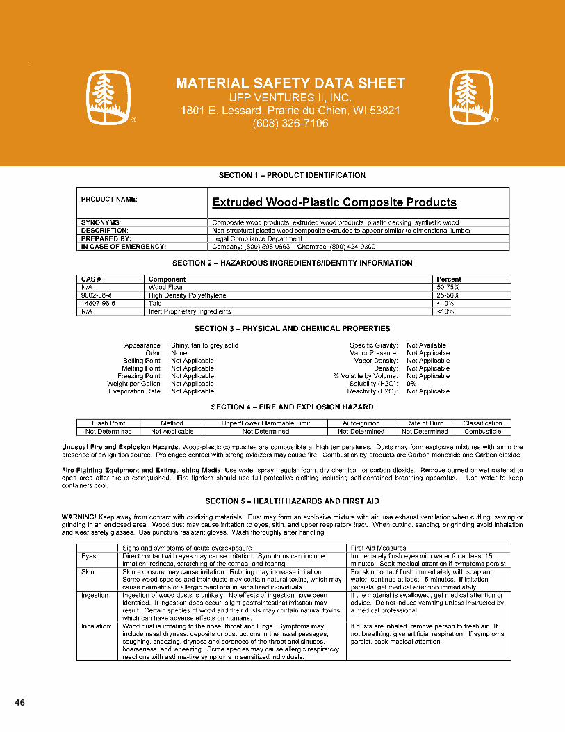
46

47

Latitudes® Compass Program and
Latitudes Certified Installer
Latitudes Rewards
Earn a NASCAR® weekend, a Weber® grill or other great prizes. There are more than 3,500 items from which to select. Every time you purchase Latitudes decking or railing products, you earn points. And since they don’t expire annually, you can redeem them for prizes, save up for that trip, or roll unused points over until next year. You’ll earn points every time you complete a Latitudes deck project. One award point is rewarded for each $1 of Latitudes products* purchased. (All Latitudes Decking and Railing components are included.)
Bonus consideration: Enrolled contractors earn double points for their first purchase! (Minimum purchase of $500 required.) You can also register online to receive an additional 500 bonus points!
Latitudes Certified Installers
To boost your business potential, become a Latitudes Certified Installer.
Only the most professional, reliable and skilled builders qualify for this prestigious program. Could this be you?
The sales leads generated by our marketing programs will come your way. You’ll receive advance information on new Latitudes product introductions, plus a helpful kit that will help you sell Latitudes more effectively. And you’ll be listed on the Latitudes website as an official Latitudes Certified Installer.
LatitudesDeck.com/pro
* Universal holds the right to randomly audit the projects to ensure compliance with the program.
© 2006-2012UniversalForestProducts,Inc. All rights reserved.
Latitudes is a registered trademark of UniversalForestProducts,Inc.,intheU.S. and of its affiliates in other countries.
Latitudes Capricorn and Equator are registered trademarks of UniversalConsumerProducts,Inc., in the U.S.
Facebook is a registered trademark of Facebook, Inc., in the U.S.
YOUTUBE is a registered trademark of Google Inc., in the U.S.
Twitter is a registered trademark of Twitter, Inc., in the U.S.
Latitudes Intrepid, Latitudes Luster and Fastball are trademarks ofUniversalConsumerProducts,Inc.
Strandex is a registered trademark of Strandex Corporation in the U.S.
Weber is a registered trademark of Weber-StephenProductsCo.intheU.S.
NASCAR is a registered trademark of National Association for Stock Car Auto Racing, Inc. in the U.S.
7120 12/12
When you choose Latitudes® Decking and Railing, there’s no limit to howfaryouandyourbusinesscango.ParticipateintheLatitudesCompassProgram—forbuildersandcontractorsonly—andyoucan earn great gifts and become an approved Latitudes Certified Installer.
Latitudes would like to invite you to become
a fan and post your thoughts on all things
decking. Share your Latitudes deck projects
and stories on our fan page.
LatitudesDeck.com/Facebook
Follow LatitudesDeck on Twitter as we
Tweet about new products, promotions
and industry news.
Twitter.com/LatitudesDeck
Visit the LatitudesDeck YouTube channel
to view the latest how-to videos, on location
videos and more.
LatitudesDeck.com/youTube
Check out our Decking and Outdoor Living
blog for all things decking and outdoor living.
Blog.ufpi.com
Design your dream deck online in minutes
with Latitudes Deck Visualizer.
LatitudesDeck.com/Visualizer
Get the free mobile app at http://gettag.mobi
Scan code to learn more about Latitudes
Decking and Railing.
1801 E. LessardPrairieduChien,WI53821
877.463.8379
LatitudesDeck.com
Latitudes® On The Web
The right way to go™