contentsmarking.com.ua/instrukcii/manual printera/markem-imaje 9040 b… · contents a37605-c 5/222...
TRANSCRIPT


A37605-C3/222
Contents

Contents
A37605-C4/222
Notes:

Contents
A37605-C5/222
SAFETY 9
■ REMINDER 11 ■ SUPPLEMENT FOR MARKEM-IMAJE TECHNICIANS 11
PRINTER DESCRIPTION 19
■ WHAT’S NEW ON 9040? 21 ■ MORE FEATURES ON 9040 USER INTERFACE BOARD 21 ■ NEW SOFTWARE FEATURE: OPERATOR VARIABLE MANAGEMENT 24 ■ 9040 STRONG POINTS: 26 ■ THE RANGE 27 ■ CONFIGURATIONS 27 ■ CABINET 28 ■ OPERATOR INTERFACE 29 ■ ELECTRONIC COMPARTMENT 30 ■ HYDRAULIC COMPARTMENT 33 ■ PRINT-HEAD & UMBILICAL 34 ■ UMBILICAL CONFIGURATION 35 ■ HEAD CONFIGURATION 35 ■ ANGLED UMBILICAL ON ANGLED HEAD 35 ■ GENERAL SPECIFICATION OF THE PRINTER 36
PRODUCT FEATURES 39
■ CODE 128 41 ■ COUNTERS AND COUNTER PARAMETERS 56
COMPATIBILITY 67
■ COMPATIBILITY S8 G1 9040 69
Contents
A37605-C6/222
PRE-INSTALLATION INSTALLATION 81
■ INK JET PRESALE FORM 83 ■ OUT OF BOX CHECKING LIST 84 ■ INSTALLATION SAFETY CERTIFICATE 85 ■ INFORMATION ON NEW 9040 PC BOARD AND PCMCIA CARD 86
TROUBLESHOOTING 93
■ HEAD FAULTS 95 ■ INK CIRCUIT FAULTS 97 ■ GENERAL FAULTS 98
AFTER SALES POLICY 101
■ TIME BETWEEN SERVICES 103 ■ LIST OF POINTS TO BE CHECKED DURING STANDARD MAINTENANCE AGREEMENT (9040, S8 C2, 9040 IP65, 9040S) 104 ■ LIST OF POINTS TO BE CHECKED DURING ACCESS MAINTENANCE AGREEMENT (9040, S8 C2, 9040 IP65, 9040S) 114 ■ LIST OF POINTS TO BE CHECKED DURING STANDARD MAINTENANCE AGREEMENT (9040 CONTRAST) 121 ■ LIST OF POINTS TO BE CHECKED DURING ACCESS MAINTENANCE AGREEMENT (9040 CONTRAST) 129 ■ PREVENTIVE MAINTENANCE TABLE 136

Contents
A37605-C7/222
ELECTRONICS 139
■ INDUSTRIAL INTERFACE BOARD 141 ■ PRINT-HEAD SIGNALS ON THE MAIN BOARD 160
HYDRAULICS 163
■ INK/JET SPEED INFORMATION 165 ■ INK/JET SPEED TABLES 166 ■ INK CIRCUIT OPERATION 168 ■ INK CIRCUIT 1 HEAD 172 ■ INK CIRCUIT 2 HEADS 173 ■ ACTIVE STANDBY DIAGRAM 174 ■ ADDITION OF ADDITIVE WITH PRIMING 175 ■ LONG SHUT-DOWN 176 ■ SHORT SHUT-DOWN 177 ■ GENERAL RECAPITULATIVE “STOP”’ TABLE 178
CONFIGURATION TOOL 179
■ DIFFERENT VERSIONS OF THE CONFIGURATION TOOL 181 ■ USING THE CONFIGURATION TOOL BEFORE J40/M40 181 ■ OPTIONS DESCRIPTION OF THE CONFIGURATION TOOL BEFORE J40/M40 183 ■ USING THE CONFIGURATION TOOL SINCE J40/M40 202 ■ OPTIONS CONFIGURATION 203 ■ ETHERNET CONFIGURATION 215 ■ VERSIONS INFORMATION 217 ■ OS ACCESS 218

Contents
A37605-C8/222
Notes:

A37605-C9/222
Safety

Safety
A37605-C10/222
Notes:

Safety
A37605-C11/222
■ Reminder Please read all the safety instructions that appear in the manuals provided to the customers.
■ Supplement for Markem-Imaje technicians
Responsibility
Markem-Imaje machines must not be modified by customers without the prior permission of Markem-Imaje S.A. They must be used in accordance with the specifications in the operator's manual. Changes to non-Markem-Imaje machines must be performed by customers.
Health and Hygiene
The safety data sheet (SDS) on the following pages is provided as an example only.
Always read the SDSs for consumables used by a customer carefully.
Ink-resistant gloves and safety glasses must be worn during filling and cleaning operations. Technicians are strongly advised to wear a protective mask in the absence of a specific ventilation system.
Safety
A37605-C12/222
The electronic circuit boards pose an electrocution hazard if touched.
Fire prevention
Follow the instructions on the safety data sheet (SDS) for each consumable used to the letter.
Have a foam, CO2 or powder fire extinguisher placed in the immediate vicinity of the printer (distance of 10 meters maximum).
Do not use spark-producing equipment (drills, grinders, welders, etc.) within a 5 meter radius around the printer.)
Do not place electrical equipment (bulbs, etc.) within a 1 meter radius around the print head, particularly when performing maintenance and cleaning.

Safety
A37605-C13/222
Always keep away from open flame. Never smoke near the printer. Place a sign with the words “NO SMOKING – FLAMMABLE INK” near the printer.
Containers of ink, additive and cleaning solution must be closed and stored in a ventilated room or a fireproof cabinet.
Environment
Take the necessary precautions if the printer is used in an electrostatic environment.
System
The printer must be connected to a single-phase grounded outlet with the cord provided with it. The standard wall outlet must be above the printer in an easy-to-access location.
Handling
If the printer contains consumables, move it vertically. Do not tip it over. Drain the printer completely before moving it in a position other than vertical.
Servicing - troubleshooting
If a specific vapor exhaust system is not in use, wear the personal protective equipment mentioned earlier (mask).
NO SMOKING –
FLAMMABLE INK

Safety
A37605-C14/222
Consumables
Consumables and the printer
The Markem-Imaje printer has been factory set for the ink type selected by the customer at ordering. We strongly advise against changing the ink type. Using another type of ink, additive or cleaning product will severely damage the printer. Markem-Imaje equipment is guaranteed only if used with Markem-Imaje consumables.
Use of consumables
Refer to the safety data sheets (SDS) for the ink before using a consumable. Consumables must be used before the expiration date on the label. Beyond this date, they are no longer 100% compliant with the original specifications for use.
Safety
A37605-C15/222
Safety equipment for Markem-Imaje technicians
Code Description A20281 Safety boots Size 40 (7½ U.S.) A20282 Safety boots Size 41 (8 U.S.) A20283 Safety boots Size 42 (8½-9 U.S.) A20284 Safety boots Size 43 (9½-10 U.S.) A20285 Safety boots Size 44 (10½ U.S.) A20286 Safety boots Size 45 (11-11½ U.S.) A10937 Latex gloves - CE marked (× 20) Palm widths: 7-7.5 cm A10936 Latex gloves - CE marked (× 20) Palm widths: 8-8.5 cm A38559 Latex gloves Size XL A12762 Markem-Imaje smock Size 2 (medium) A12763 Markem-Imaje smock Size 3 (large) A12765 Markem-Imaje smock Size 4 (X-large) A16820 Markem-Imaje smock Size 5 (XX-large) A18588 Respirator A16089 Polypox liquid soap A16091 Blick 1000 barrier cream A16092 Actilis topical cream A20853 Personal eyewash A12158 Eyewash station A20592 Ear plugs A20387 Wide vision safety glasses EN6771 Additive transport case

Safety
A37605-C16/222
Rules of conduct for Markem-Imaje technicians when visiting customers
Safety
Technicians must comply with the safety rules in effect at the customer's site: Prevention plan: Technicians must request and examine the customer's prevention plan (where applicable) in advance or upon arriving at the customer's site. - Traffic areas - Authorization to use spark-producing tools - Authorizations to perform work - Necessary accreditation (chemical, electrical, etc.) If the business being visited does not provide specific equipment, technicians must wear Markem-Imaje personal protective clothing at least (see list).
System
Neither the printer nor the maintenance stand should be located in a traffic area. The entire system must be easy to access. The print head must be at least 1 meter away from all electrical devices, flames, etc. The following safety equipment must be installed near the printer: - Eyewash - Safety glasses - Appropriate gloves - Protective mask Make sure the head, conduit and printer do not vibrate. The conduit should be free of wear caused by rubbing. Check the antistatic system (antistatic brush and grounding braid) used where plastic film is manufactured/converted, extrusion is performed, surfaces rub against each other, etc. Markem-Imaje technicians are not permitted to modify the customer's electrical system. The customer is responsible for providing compressed air, electricity and other utilities. All sources of electric power should outside a 1 meter radius around the head of the machine while it is running and during cleaning/maintenance. Block drafts within the vicinity of the print heads. Check the condition of the machine power sources. Check the machine and stands for proper grounding. A suitable fire extinguisher should be located no more than 10 meters from the machine.
Safety
A37605-C17/222
Work
Leave the area clean after completing maintenance. Pick up all cloths and clean all traces of ink on the console. Dispose of waste in the appropriate receptacles (check with customer). With the customer, go over any problems that may arise on account of the system's current configuration: Training Servicing Changes Installation Maintenance tray accessibility and stability Accessories Etc. Make sure the doors on the printer close correctly. Follow up maintenance with a production check. If the printer is to be moved, obtain the customer's permission first and use the appropriate tools.

Safety
A37605-C18/222
Reminder of the main safety pictograms
XI - IRRITANT
XN - HARMFUL
FLAMMABLE F, F+,F++ EXPLOSIVE
CORROSIVE OXIDIZER
TOXIC
DANGEROUS FOR THE ENVIRONMENT

A37605-C19/222
Printer description

Printer description
A37605-C20/222
Notes:

Printer description
A37605-C21/222
■ What’s new on 9040? New design of the key board with Markem-Imaje colours A new User Interface board (called “PC board” in the past) is available from beginning of December on 9040 Series. It will offer new capabilities as a standard, such as:
Ethernet and USB port, Full compatibility with existing installed base, No more ENR parts available for such item.
A new software version is also implemented on 9040 at the same time, and offers the possibility to manage some “Operator Variables”.
■ More features on 9040 user interface board More connectivity capabilities
As a reminder, this new board: Contains the firmware and the printer data. Ensure the Man/Machine interface Ensure the connectivity between the printer and the external communication network
The new “IHM” board (ref. A37883 – see picture on next page) will come with new features as a standard: To interface the printer with the customer network:
1 Ethernet Port (using RJ45 connector) 1 “COM 1” port: optional RS232 communication for special application
To download data to or from the printer:
1 PCMCIA card reader, 1 USB port (USB2.0 compliant), 1 SD card reader.

Printer description
A37605-C22/222
New operating system
We took this new design opportunity to implement the “Windows CE” operating system (a Windows CE license sticker is applied on each board).
New software features
Printer parameters
Due to this new board, the “Printer Preparation” menu was modified accordingly to add: Data transfer using PCMCIA, USB or SD (on the previous board, only PCMCIA transfer was possible) Ethernet settings
COM1
USB port
SD card reader
PCMCIA card reader
Input / output for
special applications
Ethernet port

Printer description
A37605-C23/222
New configuration tool (for Imaje technician adjustment)
For information: thanks to Windows CE capabilities, the configuration tool offer a new “Windows like” design. This clarify the screen architecture and is more user-friendly for the technician (see the screen example hereafter).
After-sales policies
Only the ENM37883 board will be available for sales as a spare part. The ENR board (repaired board) will not be created.
Compatibility with existing 9040 printers
The new user interface board ENM37883 is full compatible with the previous 9040 PC board (ENM/ENR36929)*.
NOTE: For each upgrade or replacement, the printer software must be updated to version J40/M40.
Software version
Pc board J40/M40 J10/M40 ENM37883 √
ENM36929 √ * For S8 range, ENM/ENR36929 will be still available.

Printer description
A37605-C24/222
Phase-out
As Ethernet port is now part of the new IHM board, the Ethernet option A37271 is not necessary any more. As a consequence, this reference will be removed from the SAP configurator. Nevertheless, the ETHERNET EXTENSION BOARD for 9040 (ENM36799) will still remain available for our installed base, since we have a few boards in stock.
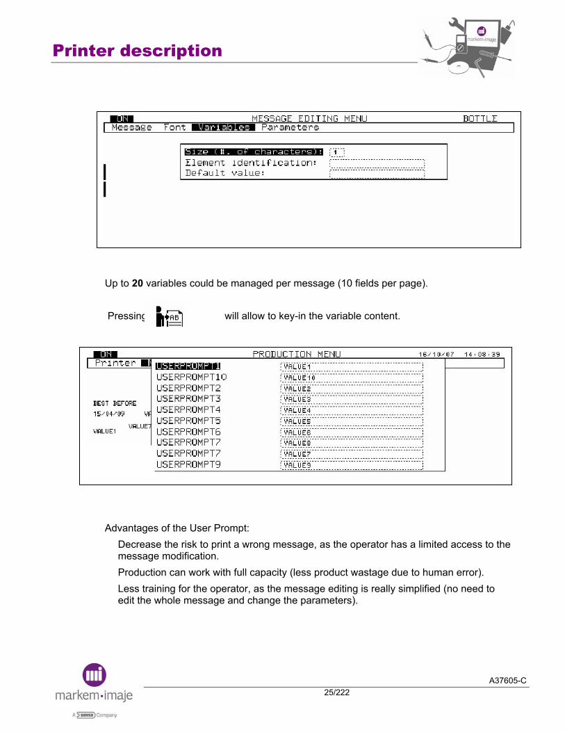
■ New software feature: operator variable management We now have the capability to define and insert one or several operator variables (also called “User Prompt”) when editing a message. A new symbol, directly linked to the “F6” shortcut key, will appear now in the bottom line of the screen, as soon as the message selected includes almost one variable operator. Each “User prompt” can be defined in the menu “Messages Editing/Variables/User Prompt” as follow:
Size of the variable (up to 99 characters) Name of the user prompt (example: “Date”) Default value: value which is printed by default if nothing is entered in production
Printer description
A37605-C25/222
Up to 20 variables could be managed per message (10 fields per page). Pressing the key will allow to key-in the variable content. Advantages of the User Prompt:
Decrease the risk to print a wrong message, as the operator has a limited access to the message modification. Production can work with full capacity (less product wastage due to human error). Less training for the operator, as the message editing is really simplified (no need to edit the whole message and change the parameters).

Printer description
A37605-C26/222
■ 9040 strong points: A lot of configurations: mono or twin-head, mono or twin-jet G, M or P, IP54 or IP65. 1 to 2 print jets per head (unique on the market) Ergonomic interface operator Large range of consumables Economic management of the consumable PCMCIA/Compact Flash for back up Logo creation Large choice of barcodes, including Datamatrix Up to 8 lines Up to 2000 messages Ethernet connection (option) IP65 rating (option) Fast connection of the main accessories
Printer description
A37605-C27/222
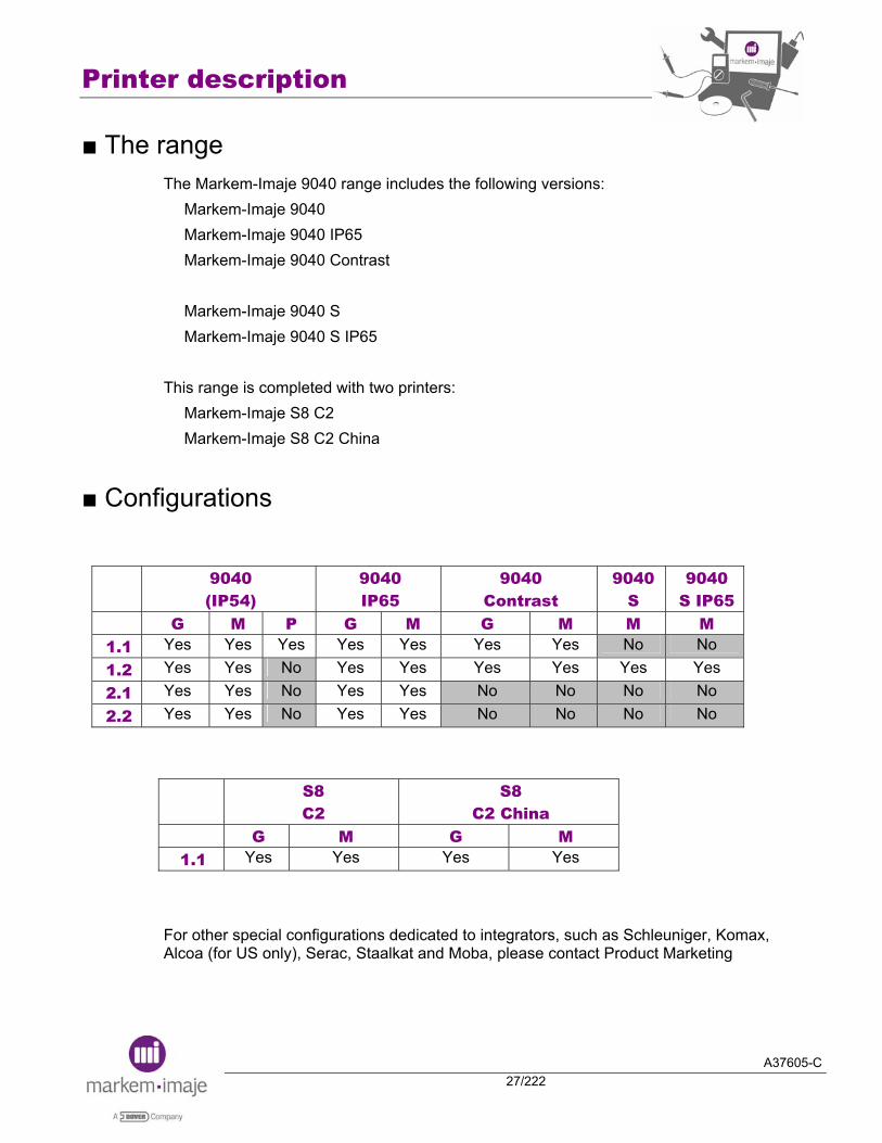
■ The range The Markem-Imaje 9040 range includes the following versions:
Markem-Imaje 9040 Markem-Imaje 9040 IP65 Markem-Imaje 9040 Contrast Markem-Imaje 9040 S Markem-Imaje 9040 S IP65
This range is completed with two printers:
Markem-Imaje S8 C2 Markem-Imaje S8 C2 China
■ Configurations
9040
(IP54) 9040 IP65
9040 Contrast
9040 S
9040 S IP65
G M P G M G M M M 1.1 Yes Yes Yes Yes Yes Yes Yes No No 1.2 Yes Yes No Yes Yes Yes Yes Yes Yes 2.1 Yes Yes No Yes Yes No No No No 2.2 Yes Yes No Yes Yes No No No No
S8 C2
S8 C2 China
G M G M 1.1 Yes Yes Yes Yes
For other special configurations dedicated to integrators, such as Schleuniger, Komax, Alcoa (for US only), Serac, Staalkat and Moba, please contact Product Marketing

Printer description
A37605-C28/222
■ Cabinet 2 types of cabinet are available:
- Ventilated IP54 - No ventilated IP65
The cabinet is compact, it is manufactured out of stainless steel (304L quality), the IP65 one requires a connection to the compressed air. The electrical connections (power supply, industrial inputs/outputs, V24…), pneumatic connections (air pressurisation) and umbilical are located behind the cabinet. Vapours extraction connection is under the cabinet.
IMPORTANT: The printer must run with the door closed.
The printer must be equipped with the stability kit or fixed on the floor.
It is possible, to use a trolley which allows to move the printer.
On IP65 version, this part does not exist. The cabinet is hermetic.
Ventilation in
Ventilation out
Stability kit option

Printer description
A37605-C29/222
■ Operator Interface The operator interface is user friendly thanks to:
A screen with icons for daily operations & consumable level indication Windows-type menu structure Help message to guide the operator through the different menu levels LED indicators which provide a quick indication of the printer status Large choice of operator languages
Operator Languages
29 operator languages are available for the printer.
English Swedish Hungarian Japanese French Danish Czech Chinese Italian Norwegian Polish Korean Spanish Finnish Croatian Thai Portuguese German Slovenian Taiwanese Greek Dutch Russian Vietnamese Hebrew Arabic Bulgarian Indonesian Brazilian
Keyboard
There are 5 keyboards available to facilitate the edition of message with non–latin alphabets.
Latin Cyrillic Chinese Arabic Hebrew

Printer description
A37605-C30/222
■ Electronic compartment The electronic compartment is located on the top of the printer. The main electronic elements are:
The mains filter (located on the radiator of power supply board) The power supply board The main board The EHT block The industrial interface board (easily accessible) The PC board The stirring board (9040 contrast)
Power supply board
Main board
Industrial interface connection board
Mains Filter
EHT Block
PCMCIA Flash or Compact Flash card with adaptator *
PC board
Stirring board (9040 Contrast only)
Printer description
A37605-C31/222
Main board
5 types of main boards are available. Mono-head, mono-jet Mono-head, twin-jet Twin-head, mono-jet Twin-head, twin-jet 9040S
The CPU and printing functions are located on the same board. The following elements are connected to the main board:
Power supply Industrial interface and accessories connectors EHT block Ink circuit Printing module PC board
Power supply board
This board supplies all voltages (24v, 15v, -15v, 5v) to all others elements.
Stirring motor board
Board connected on the CPU board. Available for S8.
Industrial interface connection board
This board allows the connection of external devices. Connectors for all inputs/outputs: photo cell, tacho, alarms (idem 9020/9030) 2 types of boards are available.
Mono-head without external link Twin-head with parallel interface and RS422
Printer description
A37605-C32/222
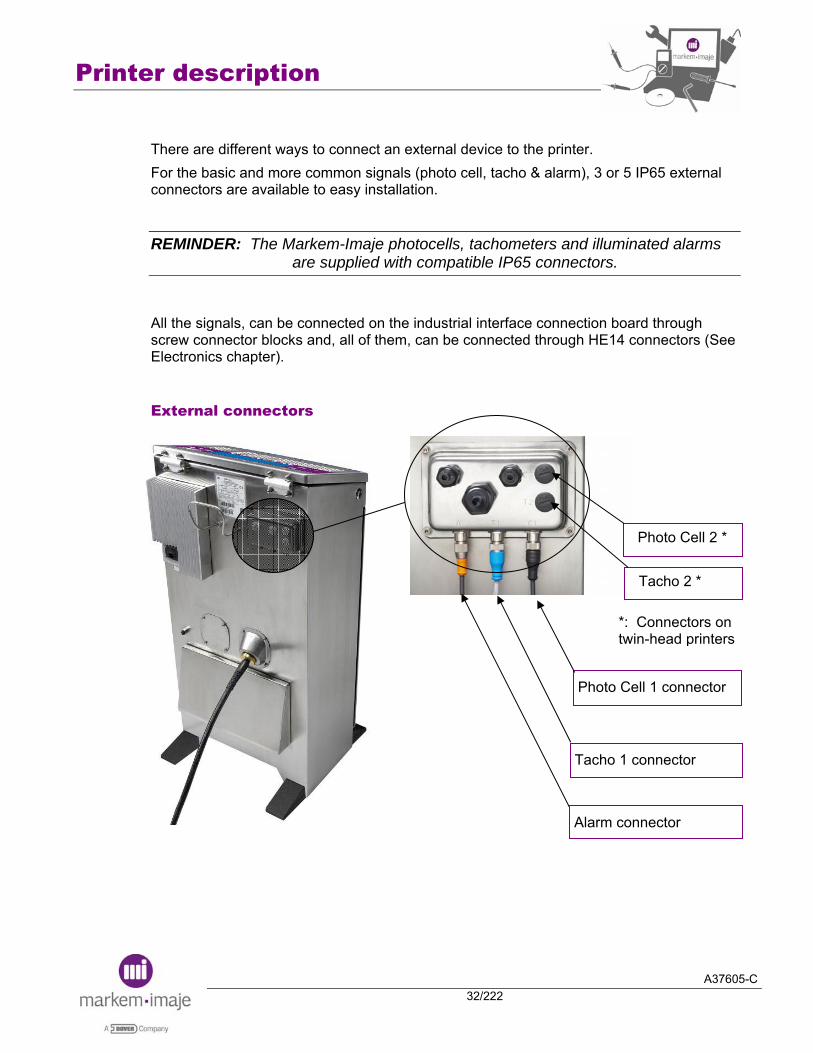
There are different ways to connect an external device to the printer. For the basic and more common signals (photo cell, tacho & alarm), 3 or 5 IP65 external connectors are available to easy installation.
REMINDER: The Markem-Imaje photocells, tachometers and illuminated alarms are supplied with compatible IP65 connectors.
All the signals, can be connected on the industrial interface connection board through screw connector blocks and, all of them, can be connected through HE14 connectors (See Electronics chapter).
External connectors
Photo Cell 1 connector
Tacho 1 connector
Tacho 2 *
Photo Cell 2 *
Alarm connector
*: Connectors on twin-head printers
Printer description
A37605-C33/222
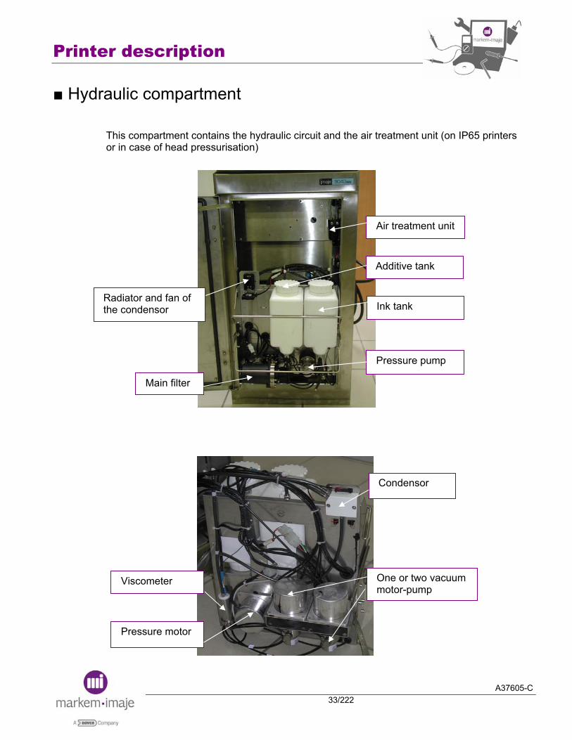
■ Hydraulic compartment This compartment contains the hydraulic circuit and the air treatment unit (on IP65 printers or in case of head pressurisation)
Radiator and fan of the condensor
Air treatment unit
Main filter
Pressure pump
Additive tank
Ink tank
Condensor
One or two vacuum motor-pump
Pressure motor
Viscometer

Printer description
A37605-C34/222
■ Print-Head & Umbilical The print head is available in 2 versions: 1 or 2 jets The print head is available in 3 different nozzle sizes:
72 µ for G head (nominal resolution: 2.8 dots/mm) 50 µ for M head (nominal resolution: 4.5 dots/mm) 38 µ for P head (nominal resolution: 7 dots/mm)
For 9040 IP65 printer, the print head is protected by a stainless steel head protection accessory (except on bent umbilicals).
REMARK: This stainless steel head protection kit is available as an accessory for 9040.
Characteristics:
1 to 2 jets per head Regulation of the jet speed One piece moulded head Unalterable head electrode alignment Head pressurization (the printer must be connected to the plant air) (option) Compound filled umbilical Bent umbilical available in some configurations Maximum umbilical axial rotation on itself: 180° in static, 0° in dynamic (no dynamic torsion) Minimum bend radius of the umbilical: 115 mm dynamic, 100 mm static Water, Mek and alcohol proof umbilical Compressible value of the umbilical: 10 bars during 30 seconds Automatic nozzle cleaning system.

Printer description
A37605-C35/222
■ Umbilical configuration The umbilical lengths available are 3, 5 and 8.35 meters. On the heads G and M, the option “bent umbilical” (angled conduit) is available in 4 configurations: (0°, 90°, 180° and 270°).
■ Head configuration On the heads G and M, the option “angled head” is available.
■ Angled umbilical on angled head
REMARK: All these configurations depending on:
the type of the head (G, M or P ; angled or not)
the type of the umbilical (length ; angled or not)
need a special part number. Please refer to the “9040 Spare Parts and Accessories Catalog”.

Printer description
A37605-C36/222
■ General specification of the printer
Operating limits
Operating temperature
□ + 5°C to + 45°C. (Use of certain ink can limit the temperature range, see ink technical data sheet).
Humidity □ 10 to 90 % without condensation.
Altitude □ 2000 m maximum.
Installation details
Working position of the printer
□ Vertical for the printer cabinet □ Any position for print head
Compliance with standard
Safety □ Conformity (self-certification): CE marking conforms with the machine directive, the electromagnetic compatibility directive and the low voltage directive: CEI 60950 (UL 60950, EN60950), CEI 60204-1 (EN60204-1).
□ Accreditations (third-party bodies): UL label according to UL 60950, CSA label according to CSA C.22.2.950, GS label according to EN 60204-1 and ZH 1/10* EX-RL/03.85.
□ EN60529 □ Vibrations NF EN 22247
NF EN 60068-2-29
Protection Mechanical parts
□ Impacts (bare product)
falls/impacts NF EN22248 NFH00 -60 NFH00-41, 47, 58, 59
□ Emissions EN 61000-6-4 Electromagnetic compatibility
□ Immunity EN 61000-6-2
Printer description
A37605-C37/222
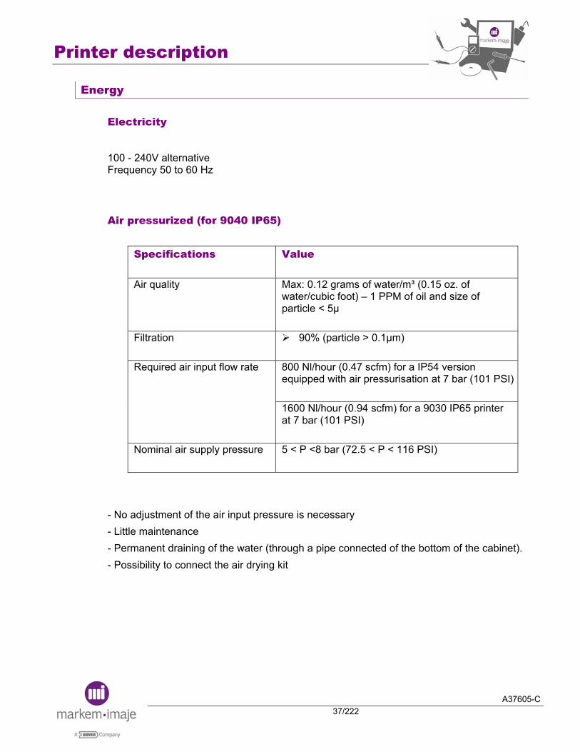
Energy
Electricity
100 - 240V alternative Frequency 50 to 60 Hz
Air pressurized (for 9040 IP65)
Specifications
Value
Air quality Max: 0.12 grams of water/m³ (0.15 oz. of water/cubic foot) – 1 PPM of oil and size of particle < 5μ
Filtration 90% (particle > 0.1μm)
Required air input flow rate 800 Nl/hour (0.47 scfm) for a IP54 version
equipped with air pressurisation at 7 bar (101 PSI)
1600 Nl/hour (0.94 scfm) for a 9030 IP65 printer at 7 bar (101 PSI)
Nominal air supply pressure 5 < P <8 bar (72.5 < P < 116 PSI)
- No adjustment of the air input pressure is necessary - Little maintenance - Permanent draining of the water (through a pipe connected of the bottom of the cabinet). - Possibility to connect the air drying kit

Printer description
A37605-C38/222
Notes:

A37605-C39/222
Product features

Product features
A37605-C40/222
Notes:

Product features
A37605-C41/222
In this chapter, only two functions are described.
■ Code 128 Availability in the range
Code128 Markem-Imaje 9040
General Definition
The Code 128 is a very effective, high-density symbology which permits the encoding of alphanumeric data. This symbology has been widely implemented in many applications where a relatively large amount of data must be encoded in a relatively small amount of space. Code 128 is a continuous, multilevel, full ASCII code. Each of the Code 128 characters consists of three bars and three spaces. The bars and spaces may be one, two, three, or four modules wide. The total length of each code 128 character is eleven modules, with the total length of the bar modules odd, and the total length of the space modules even. The character set consists of 103 different characters, three different start characters, and one unique stop character. Three different start characters determine which character set will be used in the following encoding. The character set may also be changed in the middle of the barcode thanks to three shift codes. For example, the barcode starts in "Character set A" to encode the text "Markem-Imaje", and then switches to "Character set C" to more efficiently encode the numbers "9040". With the three different start characters, there are three different code subsets available. They are:
Using the "A" start character - All upper case alphanumeric characters plus all of the ASCII control characters. Using the "B" start character - All upper and lower case alphanumeric characters. Using the "C" start character - Double density numeric characters, all number pairs from 00 to 99.
The symbology includes a checksum digit for verification, and the barcode may also be verified character-by-character verifying the parity of each data byte.

Product features
A37605-C42/222
Code 128 in 9040
A message can contain up to 4 barcodes. With 9040, we are able to manage the code 128 with the code set A, B and C. A maximum of 50 characters can be inserted in the code 128 barcode in using the code set A or B and up to 100 characters in using the code set C (the special characters NUL, SOH, STX etc and the shift code to switch to another characters set are counted for one character each time). When we create a new code 128 barcode on the Keyboard, that is the code set B by default.
That is possible to select another Code set at the beginning of the code.
During the barcode edition, it is possible to change the code set in the middle of the barcode.
Product features
A37605-C43/222
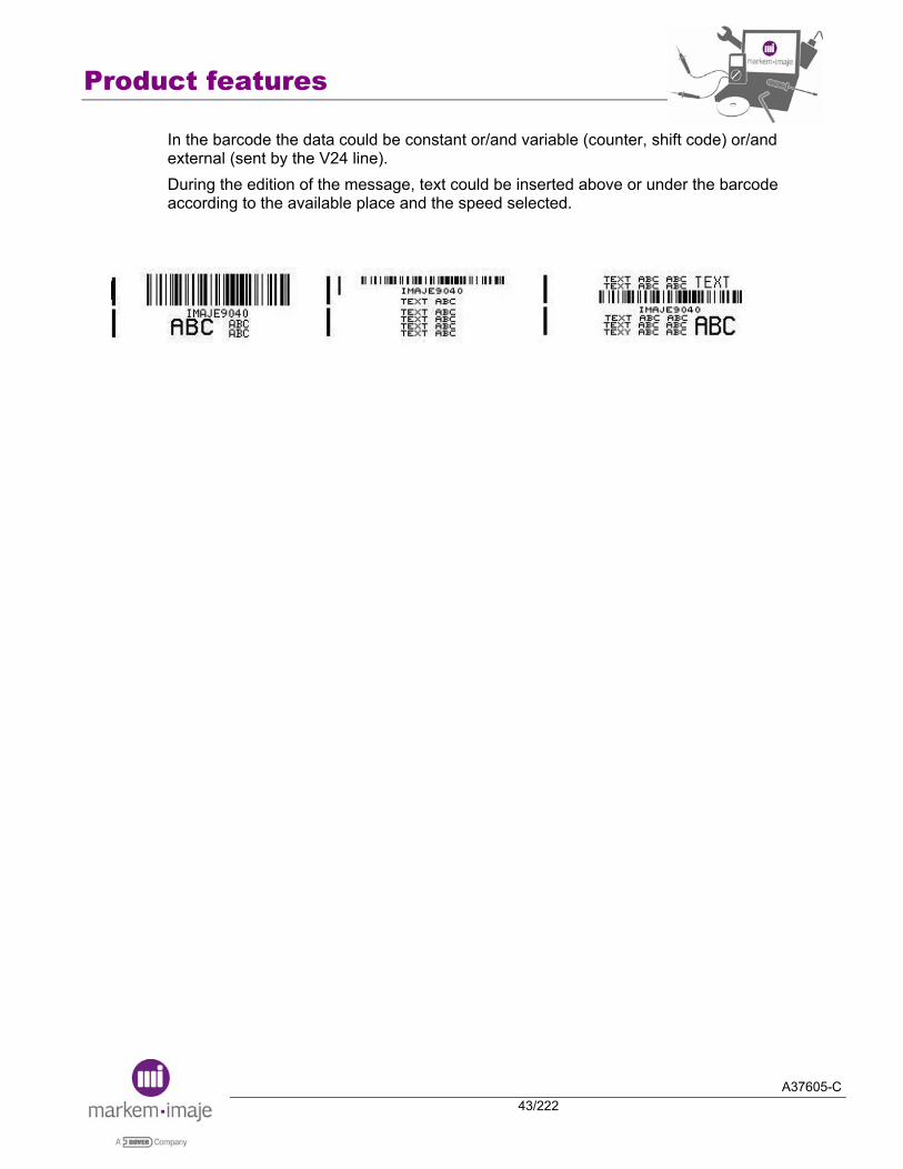
In the barcode the data could be constant or/and variable (counter, shift code) or/and external (sent by the V24 line). During the edition of the message, text could be inserted above or under the barcode according to the available place and the speed selected.

Product features
A37605-C44/222
Parameters used
In the barcode parameters, it is possible to choose if the readable text will be printed or not according to edition height:
If the height bar with height font is superior to edition height, the barcode is inserted without the text If the height bar is superior to edition height, the barcode is not inserted
When the readable text and the bar are present on the same jet, there are 3 "blank" drops between the text and the bar.
Code128: The height parameter ‘JET’ is not adjustable and fixed to maximum height edition. ½Code128: It is allowed to choose the height of the bar.
The code 128 can be printed with the font raster available in the printer or with the full jet raster:
1G Head: Maximum height (full jet raster) = 27 dots (maximum printing speed = 372 mm/s) 1M Head: Maximum height (full jet raster) = 24 dots
"Inverse Print" parameter allows the barcode to be printed in inverse video. "Optimization" parameter allows to automatically switching in code C in the barcode, when there are enough numeric digit in order to get a code of smaller length. "Optimization" parameter is not available through the V24 protocol.
Product features
A37605-C45/222
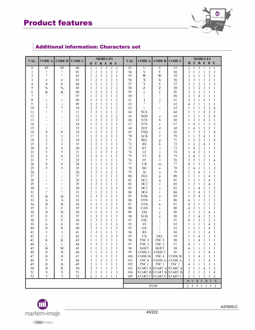
Additional information: Characters set
Product features
A37605-C46/222
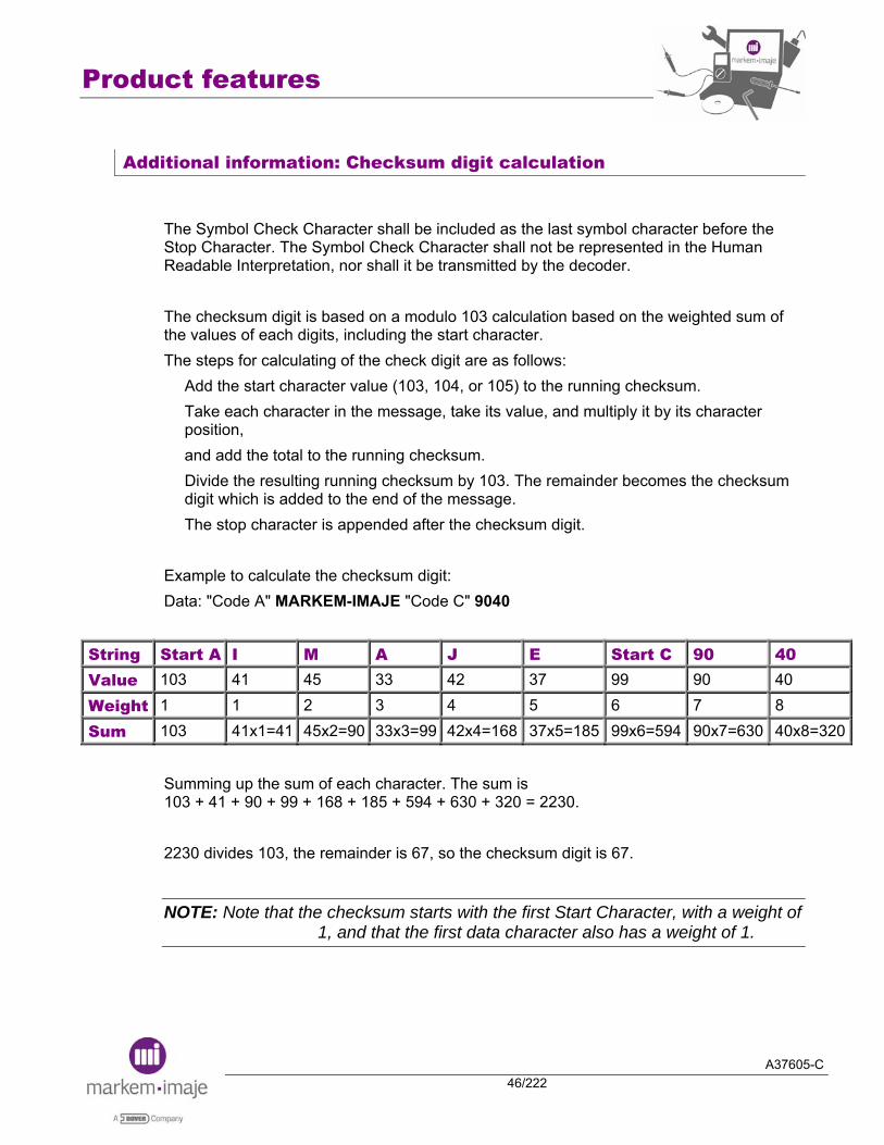
Additional information: Checksum digit calculation
The Symbol Check Character shall be included as the last symbol character before the Stop Character. The Symbol Check Character shall not be represented in the Human Readable Interpretation, nor shall it be transmitted by the decoder. The checksum digit is based on a modulo 103 calculation based on the weighted sum of the values of each digits, including the start character. The steps for calculating of the check digit are as follows:
Add the start character value (103, 104, or 105) to the running checksum. Take each character in the message, take its value, and multiply it by its character position, and add the total to the running checksum. Divide the resulting running checksum by 103. The remainder becomes the checksum digit which is added to the end of the message. The stop character is appended after the checksum digit.
Example to calculate the checksum digit: Data: "Code A" MARKEM-IMAJE "Code C" 9040
String Start A I M A J E Start C 90 40 Value 103 41 45 33 42 37 99 90 40 Weight 1 1 2 3 4 5 6 7 8 Sum 103 41x1=41 45x2=90 33x3=99 42x4=168 37x5=185 99x6=594 90x7=630 40x8=320
Summing up the sum of each character. The sum is 103 + 41 + 90 + 99 + 168 + 185 + 594 + 630 + 320 = 2230. 2230 divides 103, the remainder is 67, so the checksum digit is 67.
NOTE: Note that the checksum starts with the first Start Character, with a weight of 1, and that the first data character also has a weight of 1.
Product features
A37605-C47/222
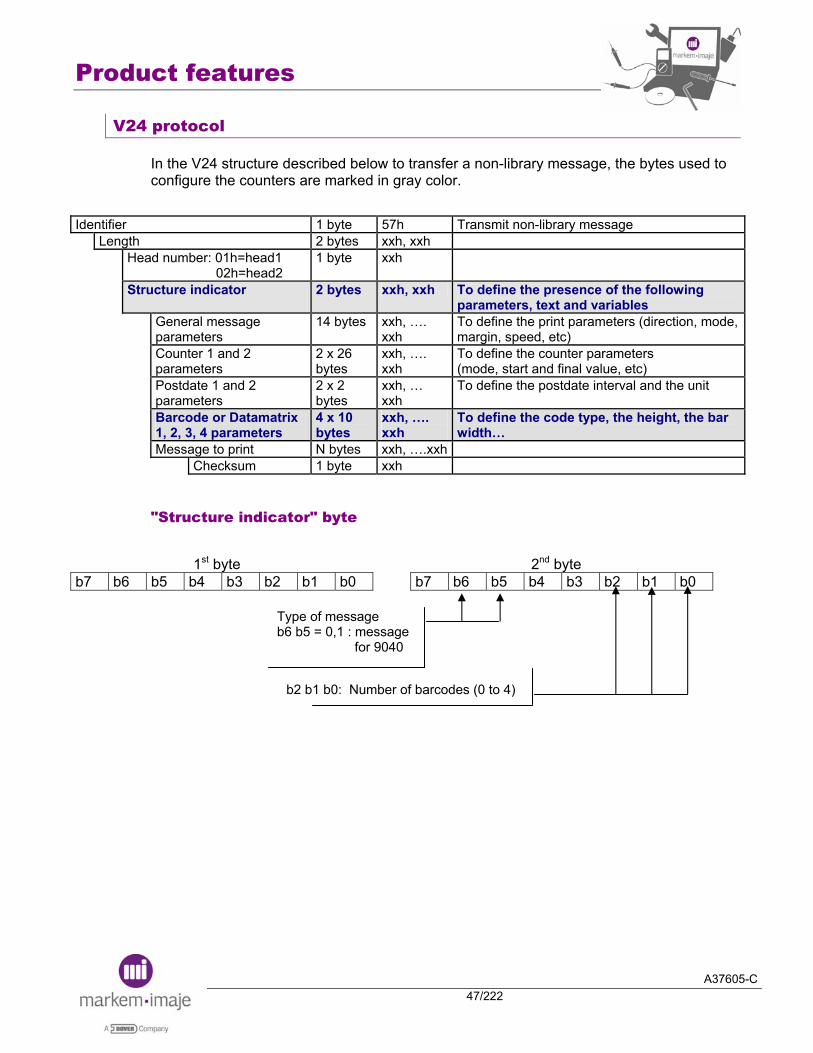
V24 protocol
In the V24 structure described below to transfer a non-library message, the bytes used to configure the counters are marked in gray color.
Identifier 1 byte 57h Transmit non-library message Length 2 bytes xxh, xxh
Head number: 01h=head1 02h=head2
1 byte xxh
Structure indicator 2 bytes xxh, xxh To define the presence of the following parameters, text and variables
General message parameters
14 bytes xxh, …. xxh
To define the print parameters (direction, mode, margin, speed, etc)
Counter 1 and 2 parameters
2 x 26 bytes
xxh, …. xxh
To define the counter parameters (mode, start and final value, etc)
Postdate 1 and 2 parameters
2 x 2 bytes
xxh, … xxh
To define the postdate interval and the unit
Barcode or Datamatrix 1, 2, 3, 4 parameters
4 x 10 bytes
xxh, …. xxh
To define the code type, the height, the bar width…
Message to print N bytes xxh, ….xxh Checksum 1 byte xxh
"Structure indicator" byte
1st byte 2nd byte b7 b6 b5 b4 b3 b2 b1 b0 b7 b6 b5 b4 b3 b2 b1 b0
b2 b1 b0: Number of barcodes (0 to 4)
Type of message b6 b5 = 0,1 : message for 9040
Product features
A37605-C48/222
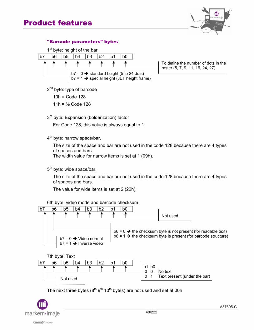
"Barcode parameters" bytes
1st byte: height of the bar b7 b6 b5 b4 b3 b2 b1 b0
2nd byte: type of barcode 10h = Code 128 11h = ½ Code 128
3rd byte: Expansion (bolderization) factor For Code 128, this value is always equal to 1
4th byte: narrow space/bar. The size of the space and bar are not used in the code 128 because there are 4 types of spaces and bars. The width value for narrow items is set at 1 (09h).
5th byte: wide space/bar. The size of the space and bar are not used in the code 128 because there are 4 types of spaces and bars. The value for wide items is set at 2 (22h).
6th byte: video mode and barcode checksum b7 b6 b5 b4 b3 b2 b1 b0
7th byte: Text b7 b6 b5 b4 b3 b2 b1 b0
The next three bytes (8th 9th 10th bytes) are not used and set at 00h
b7 = 0 standard height (5 to 24 dots) b7 = 1 special height (JET height frame)
To define the number of dots in the raster (5, 7, 9, 11, 16, 24, 27)
b7 = 0 Video normal b7 = 1 Inverse video
Not used
b6 = 0 the checksum byte is not present (for readable text) b6 = 1 the checksum byte is present (for barcode structure)
Not used
b1 b0 0 0 No text 0 1 Text present (under the bar)

Product features
A37605-C49/222
"Barcode bytes" in the text block
In the block text, a similar protocol can be used for the bar and the readable text of the barcode. The b7 of the "definition of the code" allows to configure the bar or the text mode.
Barcode delimiter 1Fh
Definition of the code 1 byte
Data to be encoded + 1 byte for the check digit of the barcode
Barcode delimiter1Fh
b7 b6 b5 b4 b3 b2 b1 b0
b7 = 0 bar of the code b7 = 1 text of the code
Parameter table index (1, 2, 3, 0)
Internal use (IHM)
Not used = 0
Product features
A37605-C50/222
NOTE 1: The size of the space and bar are not used in the code 128 because there are 4 types of spaces and bars. In the V24 barcode parameters, it is recommended to set the narrow space/bar at 1 frame and the wide space/bar at 2 frames.
NOTE 2: In the V24 barcode structure, one byte has to be inserted at the end of the data barcode for the barcode check digit (30h for example). The value of this byte will be automatically recalculated by the printer for the check digit value.
NOTE 3: In the V24 barcode structure, we can use the ASCII table to insert the characters bytes. If we use the Code 128 characters table, we have to add 20h to the characters to be encoded. In the code A, we have to add 20h to the special characters (NUL, SOH, STX…). For example, to insert STX, we have to send 62h (In the code 128 table STX = 66 decimal = 42h). In the Code C, a couple of digit have to be inserted with 2 bytes (example 07 will be 30h 37h). That is not necessary to add 20h to the variable delimiter and variable elements (counter, date, etc).
NOTE 4: In the V24 readable text structure, the start byte has to be present. The switch byte has not to be present. The check digit has not to be present.

Product features
A37605-C51/222
V24 protocol sample: Transmit a non-library message
The message is composed of 2 code 128 barcode on twin jet printer.
The first code 128 barcode is on the jet 1 with the readable text in 5 dots under the bar. The bars are in 16 dots high. The text is "MARKEM-IMAJE" with "MARKEM-IMAJE" in Code A and "9040"in Code C. The second barcode is a code 128 with the readable. The bar are located on the jet 1 using the full jet raster (30 dots). The readable text is in 7 dots font under the bar on the other jet. The text is "SN230306000000001" with in Code A. "23" is the day of the month. "03" is the month. "06" is the year. "000000001" is the counter 1.

Product features
A37605-C52/222
Identification (1 byte) 57h Length (2 bytes) 00h B5h Head number (1 byte) 01h Structure indicator (2bytes)
C4h 22h Presence of general parameter Presence of message text 1 counter / 2 barcodes
General parameter (14 bytes) Printing parameters 00h Normal sense / Tacho mode off / Object Multitop mode 00h Disabled Object top filter & Tacho division 01h 01h Filter = 100 Forward margin 00h 03h 3 mm Return margin 00h 03h 3 mm Interval 00h 03h 3 mm Printing speed 00h 64h 100 mm/s Algorithm number 00h 00h Auto Parameters for counter1 (26 bytes) Counter parameters 89h 80h Leading zeros / 9 digits Start value in ASCII 8 x 30h
31h Start value = 000000001
End value in ASCII 9 x 39h End value = 999999999 Counter step in ASCII 30h 31h Counter step = 01 Batch counter in ASCII 00h 00h
00h 01h Batch counter = 000001
Parameters for barcode1 (10 bytes) Height 10h 16 dots Type of barcode 11h ½ Code 128 Bolderization 01h Bold = 1 Narrow space / Narrow bar 09h 1 frame Wide space / Wide bar 22h 2 frames Mode video / control byte 40h Video normal & with control byte Position of the text 01h Text present Reserved 3 x 00h unused Parameters for barcode2 (10 bytes) Height 9Bh Full jet raster Type of barcode 11h ½ Code 128 Bolderization 01h Bold = 1 Narrow space / Narrow bar 09h 1 frame Wide space / Wide bar 22h 2 frames Mode video / control byte 40h Video normal & with control byte Position of the text 01h Text under the code Reserved 3 x 00h unused
Product features
A37605-C53/222
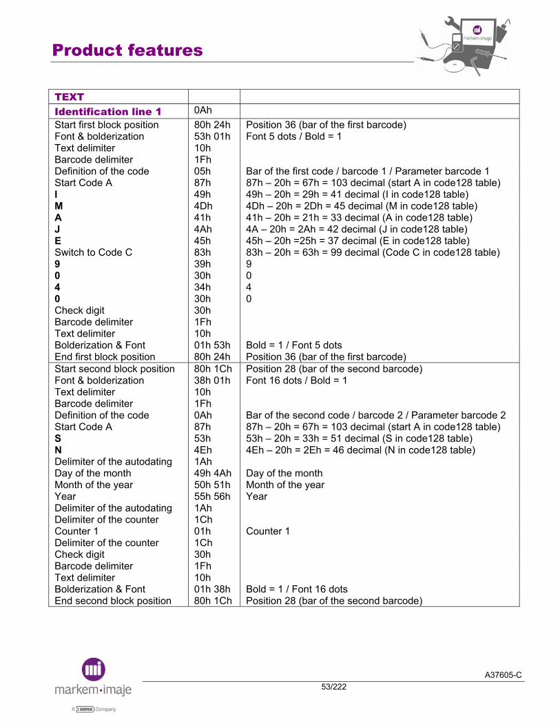
TEXT Identification line 1 0Ah Start first block position 80h 24h Position 36 (bar of the first barcode) Font & bolderization 53h 01h Font 5 dots / Bold = 1 Text delimiter 10h Barcode delimiter 1Fh Definition of the code 05h Bar of the first code / barcode 1 / Parameter barcode 1 Start Code A 87h 87h – 20h = 67h = 103 decimal (start A in code128 table) I 49h 49h – 20h = 29h = 41 decimal (I in code128 table) M 4Dh 4Dh – 20h = 2Dh = 45 decimal (M in code128 table) A 41h 41h – 20h = 21h = 33 decimal (A in code128 table) J 4Ah 4A – 20h = 2Ah = 42 decimal (J in code128 table) E 45h 45h – 20h =25h = 37 decimal (E in code128 table) Switch to Code C 83h 83h – 20h = 63h = 99 decimal (Code C in code128 table) 9 39h 9 0 30h 0 4 34h 4 0 30h 0 Check digit 30h Barcode delimiter 1Fh Text delimiter 10h Bolderization & Font 01h 53h Bold = 1 / Font 5 dots End first block position 80h 24h Position 36 (bar of the first barcode) Start second block position 80h 1Ch Position 28 (bar of the second barcode) Font & bolderization 38h 01h Font 16 dots / Bold = 1 Text delimiter 10h Barcode delimiter 1Fh Definition of the code 0Ah Bar of the second code / barcode 2 / Parameter barcode 2 Start Code A 87h 87h – 20h = 67h = 103 decimal (start A in code128 table) S 53h 53h – 20h = 33h = 51 decimal (S in code128 table) N 4Eh 4Eh – 20h = 2Eh = 46 decimal (N in code128 table) Delimiter of the autodating 1Ah Day of the month 49h 4Ah Day of the month Month of the year 50h 51h Month of the year Year 55h 56h Year Delimiter of the autodating 1Ah Delimiter of the counter 1Ch Counter 1 01h Counter 1 Delimiter of the counter 1Ch Check digit 30h Barcode delimiter 1Fh Text delimiter 10h Bolderization & Font 01h 38h Bold = 1 / Font 16 dots End second block position 80h 1Ch Position 28 (bar of the second barcode)
Product features
A37605-C54/222
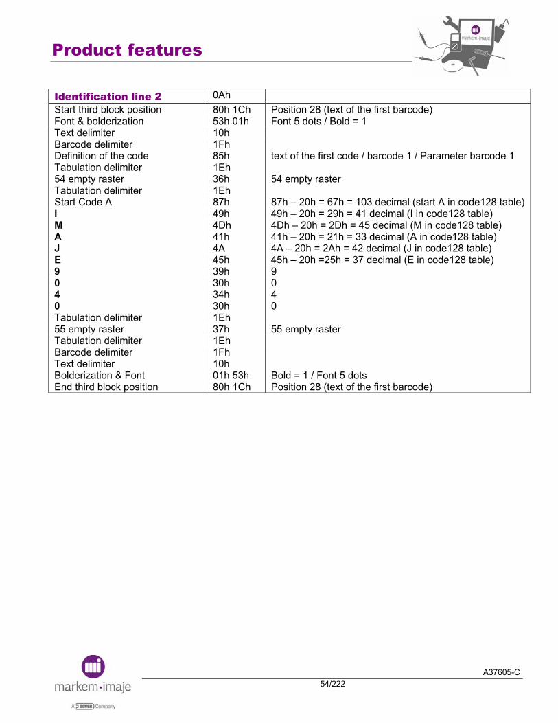
Identification line 2 0Ah Start third block position 80h 1Ch Position 28 (text of the first barcode) Font & bolderization 53h 01h Font 5 dots / Bold = 1 Text delimiter 10h Barcode delimiter 1Fh Definition of the code 85h text of the first code / barcode 1 / Parameter barcode 1 Tabulation delimiter 1Eh 54 empty raster 36h 54 empty raster Tabulation delimiter 1Eh Start Code A 87h 87h – 20h = 67h = 103 decimal (start A in code128 table) I 49h 49h – 20h = 29h = 41 decimal (I in code128 table) M 4Dh 4Dh – 20h = 2Dh = 45 decimal (M in code128 table) A 41h 41h – 20h = 21h = 33 decimal (A in code128 table) J 4A 4A – 20h = 2Ah = 42 decimal (J in code128 table) E 45h 45h – 20h =25h = 37 decimal (E in code128 table) 9 39h 9 0 30h 0 4 34h 4 0 30h 0 Tabulation delimiter 1Eh 55 empty raster 37h 55 empty raster Tabulation delimiter 1Eh Barcode delimiter 1Fh Text delimiter 10h Bolderization & Font 01h 53h Bold = 1 / Font 5 dots End third block position 80h 1Ch Position 28 (text of the first barcode)

Product features
A37605-C55/222
Start fourth block position 80h 09h Position 9 (text of the second barcode) Font & bolderization 38h 01h Font 16 dots / Bold = 1 Text delimiter 10h Barcode delimiter 1Fh Definition of the code 8Ah text of the second code / barcode 2 / Parameter barcode 2 Tabulation delimiter 1Eh 80 empty raster 1Dh 29 empty raster Tabulation delimiter 1Eh Start Code A 87h 87h – 20h = 67h = 103 decimal (start A in code128 table) S 53h 53h – 20h = 33h = 51 decimal (S in code128 table) N 4Eh 4Eh – 20h = 2Eh = 46 decimal (N in code128 table) Delimiter of the autodating 1Ah Day of the month 49h 4Ah Day of the month Month of the year 50h 51h Month of the year Year 55h 56h Year Delimiter of the autodating 1Ah Delimiter of the counter 1Ch Counter 1 01h Counter 1 Delimiter of the counter 1Ch Tabulation delimiter 1Eh 80 empty raster 1Dh 29 empty raster Tabulation delimiter 1Eh Barcode delimiter 1Fh Text delimiter 10h Bolderization & Font 01h 38h Bold = 1 / Font 16 dots End fourth block position 80h 09h Position 9 (text of the second barcode) End message delimiter + checksum
0Dh 69h
Product features
A37605-C56/222
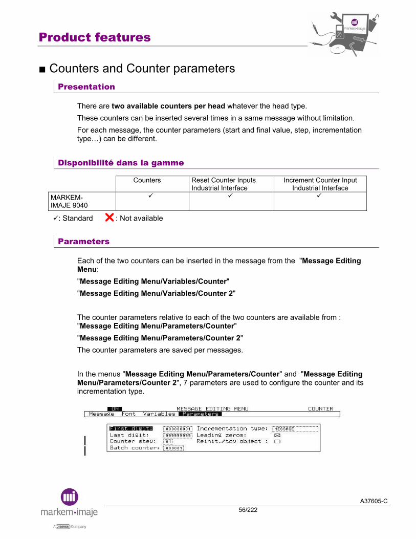
■ Counters and Counter parameters Presentation
There are two available counters per head whatever the head type. These counters can be inserted several times in a same message without limitation. For each message, the counter parameters (start and final value, step, incrementation type…) can be different.
Disponibilité dans la gamme
Counters Reset Counter Inputs Industrial Interface
Increment Counter Input Industrial Interface
MARKEM-IMAJE 9040
: Standard : Not available
Parameters
Each of the two counters can be inserted in the message from the "Message Editing Menu: "Message Editing Menu/Variables/Counter" "Message Editing Menu/Variables/Counter 2" The counter parameters relative to each of the two counters are available from : "Message Editing Menu/Parameters/Counter" "Message Editing Menu/Parameters/Counter 2" The counter parameters are saved per messages. In the menus "Message Editing Menu/Parameters/Counter" and "Message Editing Menu/Parameters/Counter 2", 7 parameters are used to configure the counter and its incrementation type.

Product features
A37605-C57/222
First digit:
This parameter allows to choose the start counter value. From 000 000 000 to 999 999 999.
Last digit:
This parameter allows to choose the finale counter value. From 999 999 999 to 000 000 000. After having reached the final value, the counter re-starts to its start value If the final value is less than the start value, then, the counter decrements
Counter step:
This parameter allows to choose the counter incrementation step. Minimum value : 01 Maximum value : 99
Batch counter:
This parameter allows to select the item number contained in the batch. The counter increments when the batch value is reached. Minimum value: 000 001 Maximum value: 999 999
Incrementation type:
This parameter allows to choose the incrementation type of the counter in the message. Object: The counter increments on activation of the ‘Top-Object’ input. Message: The counter increments on the message print. Ext: The counter increments on activation of the INCC1 (for head1) or INCC2 (for head2) input of the Industrial interface. Linked: This parameter is only available for the “Counter2” from "Message Editing/Menu/Parameters/Counter 2". The counter2 increments when the counter1 reaches its final value.
NOTES: When the Incrementation type = "Object", the counter increments only if the jet is ready to print (unless that the cable printing option is selected)
When the Incrementation type = "Ext", the counter increments whatever the jet status (ready to print, in fault or stopped) and whatever the printer status (ON or stand-by).

Product features
A37605-C58/222
Leading zeros:
This parameter allows to print or not the leading zeros. ⌧ The leading zeros will be printed.
The leading zeros will not be printed and replaced into back spaces
Reinit./top object:
This parameter allows to reset the counter when receiving the ‘Top Object’ signal. This parameter can be useful for the applications that use the repetitive mode. Some other parameters exist while they are not displayed in the User Interface
Reset counter:
Manual Reset: It is allowed to reset the counter values from the Production menu. Automatic Reset: The counter will be automatically reinitialized to its start value when:
At least one of the counter parameters is modified in the current message A new message is selected, and at least one of the counter parameters is different
This is because it has been considered that when one counter parameter is modified or different, it concerns a new production.
NOTE: A software option allows to avoid the automatically reset of the counter value in the two above cases.
External Reset: The counter1 of each head can be reinitialized to its start value on activation of the RAZ1/CRZ1 or RAZ2/CRZ2 input (depending of the head) of the industrial interface.
NOTES: This External Reset mode is permanently active.
When receiving an External Reset signal, the counter is reinitialized whatever the jet status (ready to print, in fault or stopped) and whatever the printer status (ON or stand-by)
External Reset through RS232 link: It is allowed to reset the counter values through RS232 link by using 3Ah sending.

Product features
A37605-C59/222
Output activation:
Two outputs FIN1/CFN1 and FIN2/CFN2 allows to know when final value of the counter1 of each head is reached.
NOTES: These two outputs are activated when the final value of the Counter1 is printed (more precisely the output is activated at the end of the printing of the margin).
Counter value modification:
It is allowed to modify the current counter value from the Production menu or through RS232 link by using 51h sending.

Product features
A37605-C60/222
Example of application
Case A: Counter incrementation in OBJECT mode With the following parameters: Set Off: "Object" Incrementation type: "Object" Reinit./top object: (no)
With the following parameters: Set Off: "Object" Incrementation type: "Message" Reinit./top object: (no)
Case B : Counter incrementation in REPETITIVE mode With the following parameters: Set Off: "Repetitive" Incrementation type: "Object" Reinit./top object: (no)
With the following parameters: Set Off: "Repetitive" Incrementation type: "Message" Reinit./top object: ⌧ (yes)
With the following parameters: Set Off: "Repetitive" Incrementation type: "Message" Reinit./top object: (no)
Product features
A37605-C61/222
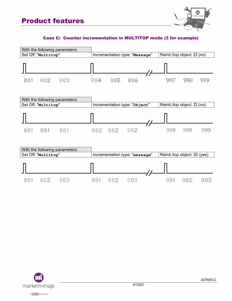
Case C: Counter incrementation in MULTITOP mode (3 for example) With the following parameters: Set Off: "Multitop" Incrementation type: "Message" Reinit./top object: (no)
With the following parameters: Set Off: "Multitop" Incrementation type: "Object" Reinit./top object: (no)
With the following parameters: Set Off: "Multitop" Incrementation type: "message" Reinit./top object: ⌧ (yes)
Product features
A37605-C62/222
V24 protocol
In the V24 structure described below to transfer a non-library message, the bytes used to configure the counters are marked in gray color.
Identifier 1 byte 57h Transmit non-library message Length 2 bytes xxh, xxh
Head number: 01h=head1 02h=head2
1 byte xxh
Structure indicator 2 bytes xxh, xxh To define the presence of the following parameters, text and variables
General message parameters
14 bytes xxh, …. xxh
To define the print parameters (direction, mode, margin, speed, etc)
Counter 1 and 2 parameters
2 x 26 bytes
xxh, …. xxh
To define the counter parameters (mode, start and final value, etc)
Postdate 1 and 2 parameters
2 x 2 bytes
xxh, … xxh
To define the postdate interval and the unit
Barcode or Datamatrix 1, 2, 3, 4 parameters
4 x 10 bytes
xxh, …. xxh
To define the code type, the height, the bar width…
Message to print N bytes xxh, ….xxh Checksum 1 byte xxh
Structure indicator bytes 1st byte 2nd byte b7 b6 b5 b4 b3 b2 b1 b0 b7 b6 b5 b4 b3 b2 b1 b0
b3 b2 : Number of counters (0 to 2) Type of message b6 b5 = 0,1 : message for 9040

Product features
A37605-C63/222
Counter parameters bytes
The 26 bytes below must be configured for a counter. Each counter has a corresponding 26-byte configuration.
1st byte b7 b6 b5 b4 b3 b2 b1 b0
Display leading zeros 1 = yes 0 = no (replaced by spaces)
Not used
Counter initialization on object pulse 0 = no 1 = yes
Number of significant digits : 1 to 9
0 = increment 1 = decrement

Product features
A37605-C64/222
2nd byte: Incrementation type b7 b6 b5 b4 b3 b2 b1 b0
Object 0 1 1 0 0 0 0 0 Message 1 0 0 0 0 0 0 0 Ext 0 0 1 0 0 0 0 1 Linked (only for Counter2) 0 0 0 0 0 0 0 0
The following 24 bytes are used to define the following parameters:
9 bytes to define the counter start value (ASCII). For example, to define a start value of "000000001", it has to be sent 30h 30h 30h 30h 30h 30h 30h 30h 31h. Even if the counter is defined with less than 9 digits, it is necessary to define the start value with 9 bytes. 9 bytes to define the counter final value (ASCII). For example, to define a final value of "999999999", it has to be sent 39h 39h 39h 39h 39h 39h 39h 39h 39h. Even if the counter is defined with less than 9 digits, it is necessary to define the final value with 9 bytes. 2 bytes to define the counter step (ASCII). 4 bytes to define the counter batch (only the 3 low order bytes are significant) For example, to define a counter batch of "000001", it has to be sent 00h 00h 00h 01h.
Counter bytes in the text block
Counter delimiter
1Ch Counter number 01 to 02
1 byte Barcode delimiter
1Ch
Product features
A37605-C65/222
V24 protocol sample: Transmit a non-library message
Example with a message composed of 2 counters:
The counter 1 is composed of 1 numerical digit for the digit after the coma. The counter 1 is incremented by the photocell. The step counter is 5 (xxxxx,0 xxxxx,5 xxxxx,0 xxxxx,5 xxxxx,0 xxxxx,5…) The counter 2 is composed of 5 numerical digits. The counter 2 is linked with counter 1. The step counter is 1.
Counter 1
Counter 2

Product features
A37605-C66/222
Identification (1 byte) 57h Length (2 bytes) 00h 5Ah Head number (1 byte) 01h Structure indicator (2bytes) C8h 20h Presence of general parameter
Presence of message text 2 counters / 0 post-date /0 barcode
General parameter (14 bytes) Printing parameters 00h Normal sense / Tacho mode off / Object Multitop mode 00h Disabled Object top filter & Tacko division 01h 01h Filter = 100 Forward margin 00h 03h 3 mm Return margin 00h 03h 3 mm Interval 00h 03h 3 mm Printing speed 00h 64h 100 mm/s Algorithm number 00h 00h Auto
Parameters for counter 1 (26 bytes) Counter parameters 01h 61h Leading zeros / 1 digit / object incrementation Start value in ASCII 9 x 30h Start value = 000000000 End value in ASCII 8 x 30h
35h End value = 000000005
Counter step in ASCII 30h 35h Counter step = 05 Batch counter in ASCII 00h 00h
00h 01h Batch counter = 000001
Parameters for counter 2 (26 bytes) Counter parameters 85h 00h Leading zeros / 5 digits / incrementation linked with the
precedent counter Start value in ASCII 9 x 30h Start value = 000000000 End value in ASCII 4 x 30h
5 x 39h Start value = 000099999
Counter step in ASCII 30h 31h Counter step = 01 Batch counter in ASCII 00h 00h
00h 01h Batch counter = 000001
TEXT Identification line 1 0Ah
Start first block position 80h 01h Position 01 (position of the counter 1 & 2) Character generation & expansion 34h 01h Font 7 dots / Bold = 1 Text delimiter 10h
20h 20h Counter delimiter 1Ch
Counter 2 02h Counter 2 Counter delimiter 1Ch Character “ , ” 2Ch “ , ” Counter delimiter 1Ch
Counter 1 01h Counter 1 Counter delimiter 1Ch
Text delimiter 10h Character generation & expansion 01h 34h Bold = 1 / Font 7 dots End first block position 80h 01h Position 01 (position of the counter 1 & 2)
End message delimiter + checksum 0Dh 46h

A37605-C67/222
Compatibility

Compatibility
A37605-C68/222
Notes:

Compatibility
A37605-C69/222
■ Compatibility S8 G1 9040
Information about the range
S8 Classic, Mailjet & S8Master 1.4 remain in G1 software mode. Models still available in 2006 product portfolio.
Principles
With S8G1, the structure of the message is managed line by line and jet per jet whereas the message with 9040 are managed as a whole (per head) whatever the quantity of lines (1 up to 4) and jet configuration. Printing datas = Algos such as 9020-9030. When you set up a new message Need to enter the speed value of the conveyor whatever the printing mode (standard =without encoder or Tachy = with encoder). Need to select the suitable printing algorithm for some applications (Multiple lines, G30, M20 ). These choices can be pre-selected / pre-programmed in the preference menu when we use the same type of algos.
9040 Features – Main differences with S8 G1 for new messages
Bar code: Ability to print only 4 bar-code per head (whatever the head configuration single jet or bijet) S8 GI can manage 4 per jet = 8 for Bi-jet) Industrial Bar code: It is not possible to print an industrial barcode (code 39, interleaved 2/5) with the full jet raster. Bar code (EAN;UPC & code 128): Possibility to print the readable text of the barcode or not (setting through the barcode parameters). If the speed and the algorithm allow it, it is possible to print the bar and the readable text on single jet machine Post-date: Ability to print only 2 post-dates per head (whatever the head configuration single jet or bijet). S8 GI can manage 2 per jet = 4 for Bi-jet.
Compatibility
A37605-C70/222
Post-date & table horo (custom) month: With 9040, the 1st post-date is tight to language table (month), the 2nd post-date is tight to the custom table whereas the post-dates of S8 GI are tight to the custom table but with the possibility to be customised or not.
Post Month 1 Post Month 2
Month autodating table set like the month table
S8G1 prints the month
9040 prints the month
S8G1 prints the month
9040 prints the month
Month autodating table is customised
S8G1 prints the
customised month
9040 prints the month
S8G1 prints the
customised month
9040 prints the
customised month
Shift code: 9040 can print only 2 shift codes per head (whatever the head configuration single jet or bijet) whereas S8 G1 can print 2 per jet = 4 for bi-jet. Multi-lines messages: In some multi-lines configurations (message with 5 or 7 dot fonts, position 3 or 4) , S8G1 can print faster. Multi-top: Maximum value is 256 (65536 for S8G1). Margin: Minimum gap of 3 mm between Dtop and start of printing.
Message transfer via PCMCIA card or V24 (S8 G1 9040)
Prerequisite: Fonts used in S8 G1 (source) must be available in 9040. Sending messages without parameters: If a message is sent without parameters through the V24 line, the parameters used will be the default parameters present in the menu Preparation / Message / Parameters. Specific printing data: Messages could be wrongly converted in case of messages using non standard printing data. 2x11dot font: Messages using 2x11dot font will be wrongly converted. The second line of 11dots will be positioned on the line 1(even if the 11 dots font appears only on one line). 2x11dot font & tacky mode: Messages using 2x11dot font with tacky mode may be wrongly printed (wrong print length) (even if the 11 dots font appears only on one line). G30 ou M20: If the customer uses G30 or M20 printing data, it is recommended to download only G30 or M20 algos in 9040 to get an automatic algo selection when the message is converted. If all algorithms are present in the printer, the algo number must be selected in the menu Preparation / Message / Parameters in order to force it for the conversion. Remark: with 9040, the “head – object” parameter is only used for the drop flight compensation. This parameter is not used for the algorithm selection.
Compatibility
A37605-C71/222
Multi-line 5 & 7 dot font algo: If the customer uses messages including multi lines which will necessitate the use in 9040 of multi line algos, the algo number must be selected in the menu Preparation / Message / Parameters. As it is only possible to set one algo number, the algo used in 9040 may be incorrect for some messages when converted if the conversion required different algo number. Rapid algo & Tacky mode: As the speed is not described in the G1 message structure (tacky mode), the speed must be set in the menu Preparation / Message / Parameters for the message conversion. Tacky mode: If the customer uses several messages with different print heights (7dot font, 2x7 dot font, 16 dot font, 24 dot font, etc…) and the speeds of the conveyor are close to printing speed performances of each message (if the speed of the conveyor changes according to the message), the algo used in 9040 may be incorrect for some messages when converted. Tacky division: In most cases (but not in all), tacky division will be well converted. Margin: Margin can be different (print gap). Inverted vertical mode: A message created with the inverted vertical mode on S8G1 will be wrongly converted on 9040. The lines of the same jet will be reversed between them and the text of jet 1 will be inverted with text of jet 2. Multi-top: If a message without parameters is sent to 9040, the Multi-top value (used by 9040) will be the value set in the Parameters By Default in the menu Preparation / Parameters / Message. Top Filter: If a message without parameters is sent to 9040, the Top Filter value (used by 9040) will be the value set in the Parameters By Default in the menu Preparation / Parameters / Message. Industrial barcode & full jet raster: With S8G1, if the message is composed of industrial barcode (code 39, interleaved 2/5) using the full jet raster, the barcode will be printed with 24 dots high on 9040. Distribution bar code & single jet : With S8G1 single jet, the distribution barcode is only composed of the bar (without readable text). With 9040, this type of barcode will be also converted with only the bar like S8G1 features. Distribution bar code & bi-jet: With S8G1 twin jet, the distribution barcode is composed of the bar on one jet and the readable text is placed on the other jet. With 9040, this type of barcode will be correctly converted with the bar and the readable text as S8G1 features.
V24 Compatibility (G1 protocol towards 9040)
Protocol 4Ah of S8G1 (transfer of variable data) can not run with the bi-jet configuration. Protocol 43h (request of current message) runs differently. 9040 re-sent a message with 9040 structure (architecture). Protocol 44h (request for recorded operating parameters) can not runs on 9040.

Compatibility
A37605-C72/222
Do not modify from keyboard, parameters of a complete message sent via serial S8 G1 protocol. Timing: When 9040 receives messages via serial S8 G1 protocol, V24 timing is slightly longer (ex : 100 ms for 2 lines of 7 dot font points, 10 characters per line with 9040 instead of 40 ms with S8 G1).
Direct mode: Direct mode does not run in case of G1 protocol G1 towards 9040.
Message selection by parallel interface
With S8G1, the structure of the message is managed jet per jet whereas the message with 9040 are managed as a whole (per head) whatever the quantity of lines and jet configuration. With S8G1 multi-jet configuration, a printed message is composed of one message per jet. With 9040, a printed message is composed of one message whatever the jet configuration. With S8G1, the message selection by the number on the parallel interface inputs must be done in coherence with the jet/head configuration. With 9040, the message selection by the number on the parallel interface inputs is different because the message number is still the same whatever the jet configuration. With 9040, an option is available in the configuration tool, to have an parallel interface management as S8G1.
Industrial interface
For 9040, a new industrial interface board has been designed. Some inputs – outputs available on S8G1 are no more present on 9040. ¤ Current loop is no more available on 9040 ¤ Only one output for the Sprog & Buzy signals and configuration of the output by jumper (Sprog & Buzy). Remark: Sprog and Buzy signal give the status of the printing. These 2 signals are in opposite phase. ¤ Opto-coupled DSR input is no more available. Remark: The DSR V24 input support up to 30V. ¤ On 9040, the head alarm relay management is different compared to S8G1 in order to have an unique status when the printer is ready to print. Remark: With S8G1, the head alarm relay has the same status when the printer is OFF and when the head is ready to print.
Hardware
Due to the RoHs regulation, a 9040 machine must be repaired by using 9040 parts only (RoHs compliance).

Compatibility
A37605-C73/222
9040 – G Head – Printing speed
Full algorithms: All drops are presents in the height. Multiline algorithms: Drops that are not used for the space between lines are not presents in the algorithm to increase the speed.
Full Algorithms
High Quality 30mm
Quality 10mm
Rapid 10mm
Specific
EAN RASTER
0.37 m/sec 72.8 FPM
24 dots 0.37 m/sec 72.8 FPM
0.37 m/sec 72.8 FPM
0.79 m/sec 155.5 FPM
Allowing 1 line of 24 dots font 1 line of 16 dots font Up to 2 lines 11 dots font Up to 2 lines 9 dots font Up to 3 lines 7 dots font Up to 4 lines 5 dots font
Allowing 1 line of 24 dots font 1 line of 16 dots font Up to 2 lines 11 dots font Up to 2 lines 9 dots font Up to 3 lines 7 dots font Up to 4 lines 5 dots font
Allowing 1 line of 24 dots font 1 line of 16 dots font Up to 2 lines 11 dots font Up to 2 lines 9 dots font Up to 3 lines 7 dots font Up to 4 lines 5 dots font
20 dots 0.89 m/sec 175.2 FPM Allowing 1 line of 16 dots font 1 line 11 dots font Up to 2 lines 9 dots font Up to 2 lines 7 dots font Up to 3 lines 5 dots font
18 dots 1.17 m /sec 230.3 FPM Allowing 1 line of 16 dots font 1 line 11 dots font 1 line 9 dots font Up to 2 lines 7 dots font Up to 3 lines 5 dots font
16 dots 0.39 m/sec 76.8 FPM
0.55 m/sec 108.3 FPM
1.31 m/sec 257.8 FPM
Allowing 1 line of 16 dots font 1 line 11 dots font 1 line 9 dots font Up to 2 lines 7 dots font Up to 2 lines 5 dots font
Allowing 1 line of 16 dots font 1 line 11 dots font 1 line 9 dots font Up to 2 lines 7 dots font Up to 2 lines 5 dots font
Allowing 1 line of 16 dots font 1 line 11 dots font 1 line 9 dots font Up to 2 lines 7 dots font Up to 2 lines 5 dots font
11 dots 0.93 m/se 183.1 FPM
1.86 m/sec 366.1 FPM
1 line 11 dots font 1 line 9 dots font 1 line 7 dots font Up to 2 lines 5 dots font
1 line 11 dots font 1 line 9 dots font 1 line 7 dots font Up to 2 lines 5 dots font

Compatibility
A37605-C74/222
Full Algorithms
High Quality 30mm
Quality 10mm
Rapid 10mm
Specific
9 dots 1.11 m/sec 218.5 FPM 1 line 9 dots font 1 line 7 dots font 1 line 5 dots font
2.23 m/sec 438.9 FPM 1 line 9 dots font 1 line 7 dots font 1 line 5 dots font
7 dots
0.97 m/sec 190.9FPM Allowing 1 line of 7 dots font 1 line 5 dots font
1.39 m/sec 273.6 FPM Allowing 1 line of 7 dots font 1 line 5 dots font
3.72 m/sec 732.2 FPM Allowing 1 line of 7 dots font 1 line 5 dots font
3.18 m/sec 625.9 FPM Pigment 1 line of 7 dots font 1 line 5 dots font
5 dots
1.86 m/sec 366.1 FPM Allowing 1 line of 5 dots font
5.58 m/sec 1098.3 FPM Allowing 1 line of 5 dots font
4.46 m/sec 877.9 FPM Pigment 1 line of 5 dots font
Multiline Algorithms Quality 10mm Rapid 10mm 4 x 7 dots 0.6m/sec – 118.1 FPM 4 x 5 dots 0.93m/sec – 183.1 FPM 3 x 7 dots 1.01m/sec – 198.1 FPM 3 x 5 dots 0.55m/sec – 108.3 FPM 1.39m/sec – 273.6 FPM 2 x 9 dots 0.43m/sec – 84.6 FPM 1.11m/sec – 218.5 FPM 2 x 7 dots 0.65m/sec – 128 FPM 1.48m/sec – 291.3 FPM 2 x 5 dots 0.92m/sec – 181.1 FPM 2.02m/sec – 397.6 FPM

Compatibility
A37605-C75/222
S8G1 – G Head – Printing speed
Standard Print data
High Quality 30mm
Quality 10mm
Rapid 10mm
Specific
24 dots 0.37 m/sec 0.79 m/sec 4 x 5 dots 0.36 m/sec 0.91 m/sec 3 x 7 dots 0.32 m/sec 0.66 m/sec 3 x 5 dots 0.49 m/sec 1.21 m/sec 2 x 9 dots 0.39 m/sec 1.1 m/sec 16 dots 0.39m/sec 0.61 m/sec 1.3 m/sec 2 x 7 dots 0.39m/sec 0.61 m/sec 1.56 m/sec 11 dots 0.92 m/sec 1.84 m/sec 2 x 5 dots 0.92 m/sec 2.17 m/sec 9 dots 1.1 m/sec 2.2 m/sec 7 dots 1m/sec 1.38 m/sec 3.64 m/sec 3.13 m/sec Pig5 dots 1.84 m/sec 5.41m/sec 4.35 m/sec Pig
Potential risk with G head
2 x 7 dot font: 2x7 dot font messages to be on the loop (1.56m/sec with S8G1 & 1.48m/sec with 9040). Basic Multi-lines messages: Messages made only of de multi-lines fonts (5 & 7 dots) without 11, 16 or 24 dot fonts AND at least one line is missing below a line at up position, 9040 will print slower. For instance, in the following cases:
Multi-lines & 11 dot font : Messages made of 1 line of 11 dot font with another line at upper position (5 or 7 dot font), 9040 will print slower. For instance, in the following cases:
Multi-lines 4x5 dot font & 11 or 16 dot font: Messages made of one line of 11 or 16 dot font AND 4 x5 dot font , 9040 will print slower. For instance, in the following cases:

Compatibility
A37605-C76/222
9040 – M Head – Printing speed
Full algorithms: All drops are presents in the height. Multiline algorithms: Drops that are not used for the space between lines are not presents in the algorithm to increase the speed.
Full Algorithms
High Quality 20mm
Quality 8mm
Rapid 8mm
Specific
EAN RASTER
24 dots 0.23 m/sec 45.3 FPM
0.23 m/sec 45.3 FPM
0.59 m/sec 116.1 FPM
Allowing 1 line of 24 dots font 1 line of 16 dots font Up to 2 lines 11 dots font Up to 2 lines 9 dots font Up to 3 lines 7 dots font Up to 4 lines 5 dots font
Allowing 1 line of 24 dots font 1 line of 16 dots font Up to 2 lines 11 dots font Up to 2 lines 9 dots font Up to 3 lines 7 dots font Up to 4 lines 5 dots font
Allowing 1 line of 24 dots font 1 line of 16 dots font Up to 2 lines 11 dots font Up to 2 lines 9 dots font Up to 3 lines 7 dots font Up to 4 lines 5 dots font
18 dots 0.92 m/sec 181.1 FPM Allowing 1 line of 16 dots font 1 line 11 dots font 1 line 9 dots font Up to 2 lines 7 dots font Up to 3 lines 5 dots font
16 dots 0.37 m/sec 72.8 FPM
0.97 m/sec 190.94 FPM
Allowing 1 line of 16 dots font 1 line 11 dots font 1 line 9 dots font Up to 2 lines 7 dots font Up to 2 lines 5 dots font
Allowing 1 line of 16 dots font 1 line 11 dots font 1 line 9 dots font Up to 2 lines 7 dots font Up to 2 lines 5 dots font
11 dots 0.38 m/sec 74.8 FPM
0.55 m/sec 108.3 FPM
1.42 m/sec 279.5 FPM
Allowing 1 line 11 dots font 1 line 9 dots font 1 line 7 dots font Up to 2 lines 5 dots font
1 line 11 dots font 1 line 9 dots font 1 line 7 dots font Up to 2 lines 5 dots font
1 line 11 dots font 1 line 9 dots font 1 line 7 dots font Up to 2 lines 5 dots font
9 dots 0.63 m/sec 124.0 FPM 1 line 9 dots font 1 line 7 dots font 1 line 5 dots font
7 dots 0.57 m/sec 112.2 FPM Allowing 1 line of 7 dots font 1 line 5 dots font
0.8 m/sec 157.5 FPM Allowing 1 line of 7 dots font 1 line 5 dots font
2.64 m/sec 519.6 FPM Allowing 1 line of 7 dots font 1 line 5 dots font
2.31 m/sec 454.7 FPM Pigment 1 line of 7 dots font 1 line 5 dots font
5 dots 1.68 m/sec 330.7 FPM Allowing 1 line of 5 dots font
3.7 m/sec 728.3 FPM Allowing 1 line of 5 dots font
3 m/sec 590.55 FPM Pigment 1 line of 5 dots font

Compatibility
A37605-C77/222
Multiline Algorithms
Quality 8mm Rapid 8mm
4 x 7 dots 0.37 m/sec – 72.8 FPM 4 x 5 dots 0.71 m/sec – 139.8 FPM 3 x 7 dots 0.71 m/sec – 139.8 FPM 3 x 5 dots 0.34 m/sec – 66.9 FPM 0.92 m/sec – 181.1 FPM 2 x 7 dots 0.39 m/sec – 76.7 FPM 2 x 5 dots 0.52 m/sec – 102.4 FPM 1.42 m/sec – 279.5 FPM
Full Eggs Algorithms
Resolution 2.8dots/mm
Ultra High Speed Algorithms
Resolution 2.8dots/mm
16 dots 1.28 m/sec – 252.0 FPM 7 dots 3.72 m/sec – 732.2 FPM
11 dots 1.84 m/sec – 362.2 FPM 5 dots 5.95 m/sec – 1171.2 FPM
7 dots 3.66 m/sec – 720.5 FPM 5 dots 4.17 m/sec – 820.9 FPM Multiline Eggs Algorithms
Resolution 2.8 dots/mm CAN Algorithms Head Object 14mm
Resolution 2.8 dots/mm
2 x 7 dots 1.73 m/sec – 340.5 FPM 7 dots 2.74 m/sec – 539.3 FPM 2 x 5 dots 2.26 m/sec – 444.9 FPM 2 x 7 dots 1.75 m/sec – 344.5 FPM
Compatibility
A37605-C78/222
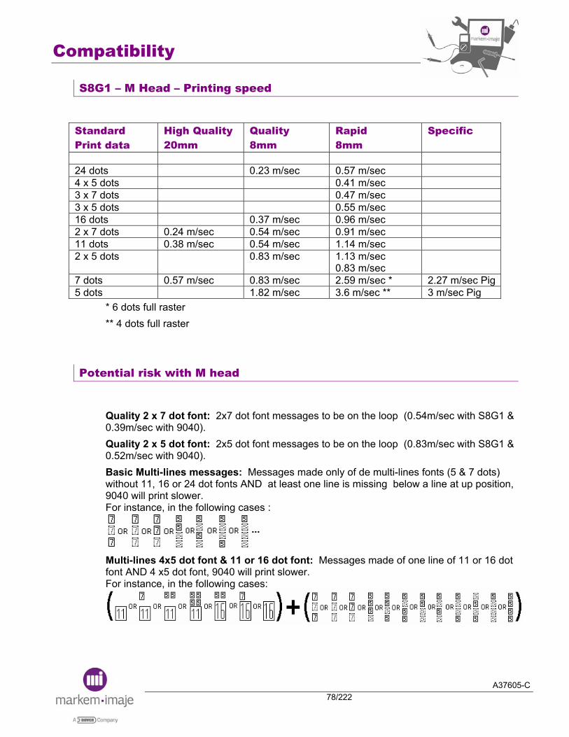
S8G1 – M Head – Printing speed
Standard Print data
High Quality 20mm
Quality 8mm
Rapid 8mm
Specific
24 dots 0.23 m/sec 0.57 m/sec 4 x 5 dots 0.41 m/sec 3 x 7 dots 0.47 m/sec 3 x 5 dots 0.55 m/sec 16 dots 0.37 m/sec 0.96 m/sec 2 x 7 dots 0.24 m/sec 0.54 m/sec 0.91 m/sec 11 dots 0.38 m/sec 0.54 m/sec 1.14 m/sec 2 x 5 dots 0.83 m/sec 1.13 m/sec
0.83 m/sec
7 dots 0.57 m/sec 0.83 m/sec 2.59 m/sec * 2.27 m/sec Pig5 dots 1.82 m/sec 3.6 m/sec ** 3 m/sec Pig
* 6 dots full raster ** 4 dots full raster
Potential risk with M head
Quality 2 x 7 dot font: 2x7 dot font messages to be on the loop (0.54m/sec with S8G1 & 0.39m/sec with 9040). Quality 2 x 5 dot font: 2x5 dot font messages to be on the loop (0.83m/sec with S8G1 & 0.52m/sec with 9040). Basic Multi-lines messages: Messages made only of de multi-lines fonts (5 & 7 dots) without 11, 16 or 24 dot fonts AND at least one line is missing below a line at up position, 9040 will print slower. For instance, in the following cases :
Multi-lines 4x5 dot font & 11 or 16 dot font: Messages made of one line of 11 or 16 dot font AND 4 x5 dot font, 9040 will print slower. For instance, in the following cases:
Compatibility
A37605-C79/222
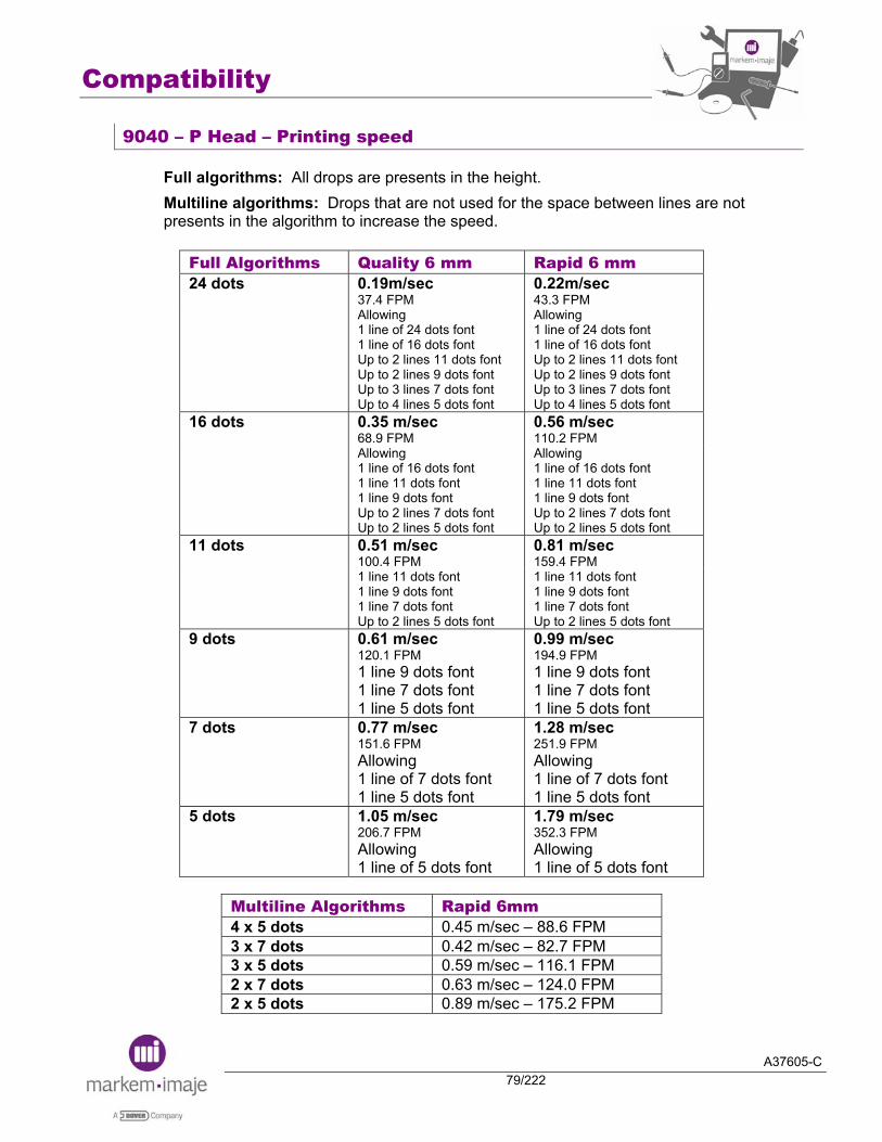
9040 – P Head – Printing speed
Full algorithms: All drops are presents in the height. Multiline algorithms: Drops that are not used for the space between lines are not presents in the algorithm to increase the speed.
Full Algorithms Quality 6 mm Rapid 6 mm 24 dots 0.19m/sec
37.4 FPM 0.22m/sec 43.3 FPM
Allowing 1 line of 24 dots font 1 line of 16 dots font Up to 2 lines 11 dots font Up to 2 lines 9 dots font Up to 3 lines 7 dots font Up to 4 lines 5 dots font
Allowing 1 line of 24 dots font 1 line of 16 dots font Up to 2 lines 11 dots font Up to 2 lines 9 dots font Up to 3 lines 7 dots font Up to 4 lines 5 dots font
16 dots 0.35 m/sec 68.9 FPM
0.56 m/sec 110.2 FPM
Allowing 1 line of 16 dots font 1 line 11 dots font 1 line 9 dots font Up to 2 lines 7 dots font Up to 2 lines 5 dots font
Allowing 1 line of 16 dots font 1 line 11 dots font 1 line 9 dots font Up to 2 lines 7 dots font Up to 2 lines 5 dots font
11 dots 0.51 m/sec 100.4 FPM
0.81 m/sec 159.4 FPM
1 line 11 dots font 1 line 9 dots font 1 line 7 dots font Up to 2 lines 5 dots font
1 line 11 dots font 1 line 9 dots font 1 line 7 dots font Up to 2 lines 5 dots font
9 dots 0.61 m/sec 120.1 FPM 1 line 9 dots font 1 line 7 dots font 1 line 5 dots font
0.99 m/sec 194.9 FPM 1 line 9 dots font 1 line 7 dots font 1 line 5 dots font
7 dots 0.77 m/sec 151.6 FPM Allowing 1 line of 7 dots font 1 line 5 dots font
1.28 m/sec 251.9 FPM Allowing 1 line of 7 dots font 1 line 5 dots font
5 dots 1.05 m/sec 206.7 FPM Allowing 1 line of 5 dots font
1.79 m/sec 352.3 FPM Allowing 1 line of 5 dots font
Multiline Algorithms Rapid 6mm 4 x 5 dots 0.45 m/sec – 88.6 FPM 3 x 7 dots 0.42 m/sec – 82.7 FPM 3 x 5 dots 0.59 m/sec – 116.1 FPM 2 x 7 dots 0.63 m/sec – 124.0 FPM 2 x 5 dots 0.89 m/sec – 175.2 FPM
Compatibility
A37605-C80/222
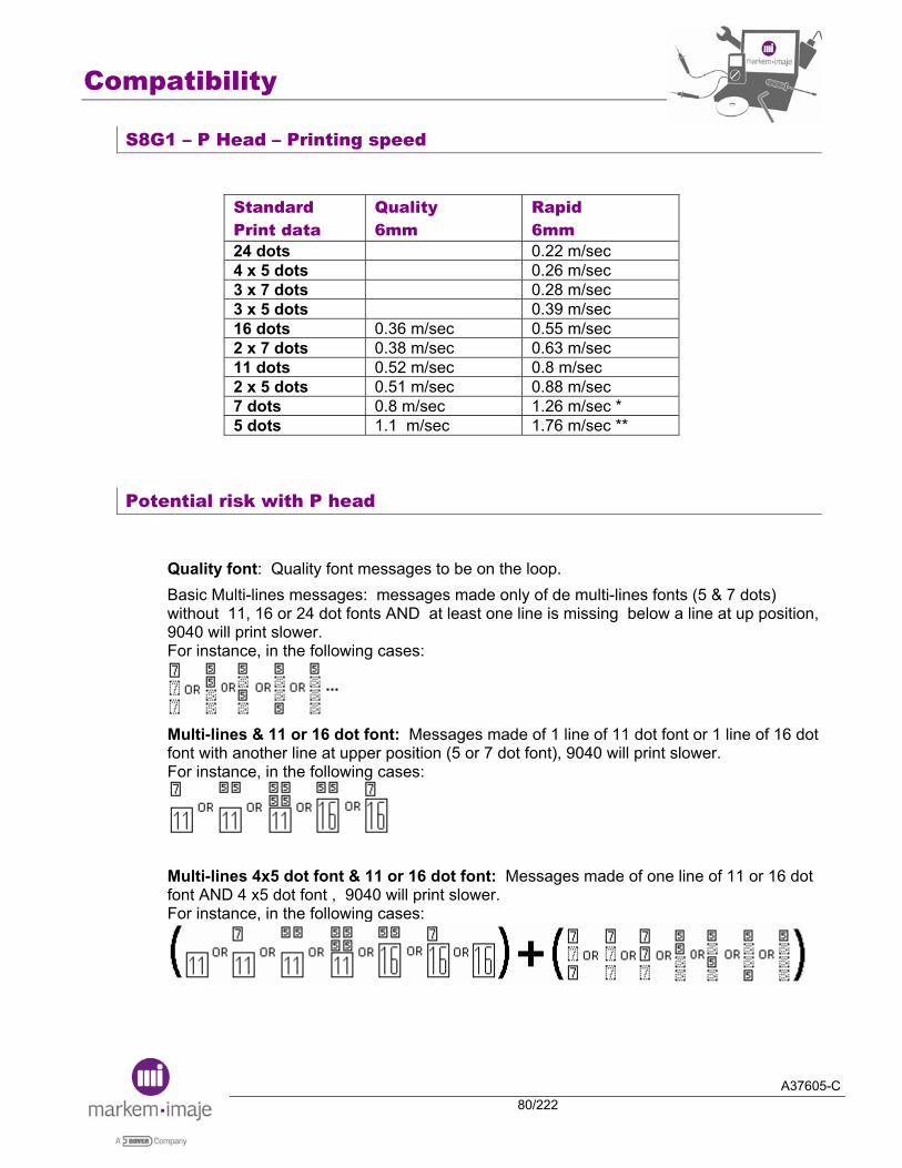
S8G1 – P Head – Printing speed
Standard Print data
Quality 6mm
Rapid 6mm
24 dots 0.22 m/sec 4 x 5 dots 0.26 m/sec 3 x 7 dots 0.28 m/sec 3 x 5 dots 0.39 m/sec 16 dots 0.36 m/sec 0.55 m/sec 2 x 7 dots 0.38 m/sec 0.63 m/sec 11 dots 0.52 m/sec 0.8 m/sec 2 x 5 dots 0.51 m/sec 0.88 m/sec 7 dots 0.8 m/sec 1.26 m/sec * 5 dots 1.1 m/sec 1.76 m/sec **
Potential risk with P head
Quality font: Quality font messages to be on the loop. Basic Multi-lines messages: messages made only of de multi-lines fonts (5 & 7 dots) without 11, 16 or 24 dot fonts AND at least one line is missing below a line at up position, 9040 will print slower. For instance, in the following cases:
Multi-lines & 11 or 16 dot font: Messages made of 1 line of 11 dot font or 1 line of 16 dot font with another line at upper position (5 or 7 dot font), 9040 will print slower. For instance, in the following cases:
Multi-lines 4x5 dot font & 11 or 16 dot font: Messages made of one line of 11 or 16 dot font AND 4 x5 dot font , 9040 will print slower. For instance, in the following cases:

A37605-C81/222
Pre-installation Installation

Pre-installation, installation
A37605-C82/222
Notes:

Pre-installation, installation
A37605-C83/222
■ Ink jet Presale Form REFERENCES
Date: Form written by: Commercial engineer: Customer name: Group : Address: Commercial contact name: Tel.: Technical contact name : Tel.: ENVIRONMENT
Temperature , max.: °C Working Temperature:
Humidity: max.: % dusty splashing
Connection: Link to BDD Network connection Message selection
LINE DESCRIPTION Conveyor speed Maxi speed: m/min Mini speed: m/min
Nb of product per year: products Maxi rate: products /hour PRODUCT DESCRIPTION
Type: size: x x mm
Substrate type: Substrate color: Ink suggested: Printing immediate result: example: dry in 2 sec, then holding at the sterilization 121°C, 30 min Printing later result: example: holding at the refrigerator, erasable at alkali, anti-migrant, etc
Printing sample: Place: Date:
PRINTING DESCRIPTION Nb of line per jet: logos barcode Message contents:
Font size: 5, 7, 9, 11, 16, 24, 2x24: Applicative: Head mounting Head movement:
Head height adjustment Acceleration: Movement:
Umbilical length: bent: Difference in level :
SUGGESTION S8: Classic, 9020, 9030,9040: Nb Jet : 1, 2 Head: G, M, P Software version Ref ink Ref Machine Derogation Specific project Integration:
Cabling, cable crossing,… Customer in charge Markem-Imaje in charge
Accessories: Comments: The customer will check that Markem-Imaje printing offer is conformed at the requirement level on term of quality and printing holding.
Name and Signature for Markem-Imaje: Name and Signature for the customer:

Pre-installation, installation
A37605-C84/222
■ Out Of Box Checking List Date: Markem-Imaje Page: 1/1 GDS.
Out Of Box Checking List. OOBCL (to be filled by Markem-Imaje technicians)
Customer: Service engineer: File name: New printer or secondhand printer: Ink: QAG-127 A Serial Number: Type: SCP Manufacturing date: Printer start up on:
1- RECEPTION: SHIPMENT & PACKING CHECK (mark-up if yes)
Did you make a Logistic Complaint ?
In case of Logistic Problem, please refer to QAG-101
2- STARTING UP: (Mark-up if yes)
Start-up<15mn ? (from on/off to ready to print)
Description of problems Remarks Canon problem
Jet not centered in the gutter
Unstable jet
Canon blocked
Exchange necessary
ELV / valve problem
ELV / valve blocked
Exchange necessary
Pressure or vacuum problem
Blockage
Leakage
Ink module or pump exchange
Motor speed or auto calibration problem
Electronic or electric problem
Electronic part exchange
Break-off point setting problem
Poor printing quality
EHT Defaults/open cover/vacuum/levels
Accessories problem
3- CONTRACT REVIEW (for local analysis) Remarks
Internal complaint Difference between the offer and customer needs Difference between offer and order
Difference between order and acknowledge of receipt Remarks
4- REMARKS Time for starting up hour
Time for complete installation hour

Pre-installation, installation
A37605-C85/222
■ Installation Safety Certificate
I hereby certify that I have read and acknowledge the safety data sheets and general conditions of use of Markem-Imaje Ink Jet Printers, as they were mentioned on Printer Manual. A copy of the material safety data sheets ( MSDS ) corresponding to the ink that I am currently using is in my possession and its contents were explained to me by __________________________________, the Markem-Imaje Technician who performed the installation. Company Name: __________________________________________
(Please Print ) Name: __________________________________________________
(Please Print ) Signature: ____________________________________
Date: ____________________________

Pre-installation, installation
A37605-C86/222
■ Information on new 9040 PC board and PCMCIA card The new PCMCIA card is now delivered with a Secure Digital card inserted into a PCMCIA adapter. This new card CANNOT be formatted into the PC board of a printer, even though the previously available card could.
Using a PCMCIA card on the new PC board
Previous PCMCIA card A27126
The previously delivered PCMCIA card was delivered as an ATA card, then delivered as a Compact Flash inserted into a PCMCIA adapter. Those cards must be formatted using the PC board of a printer.
ATA card
Compact Flash + PCMCIA adapter
USE A PRINTER TO FORMAT THOSE CARDS

Pre-installation, installation
A37605-C87/222
New PCMCIA card A27126
The new PCMCIA card A27126 is delivered with a SD card inserted into a PCMCIA adapter as of week 08. This type of PCMCIA CANNOT be formatted using the printer’s PC board. Doing so corrupts the card making it unusable. The only way to recover the new PCMCIA card formatted with a printer’s PC board is by using a laptop, and to format it again using the FAT format. SD card + PCMCIA adapter
DO NOT USE A PRINTER TO FORMAT THIS CARD
Pre-installation, installation
A37605-C88/222
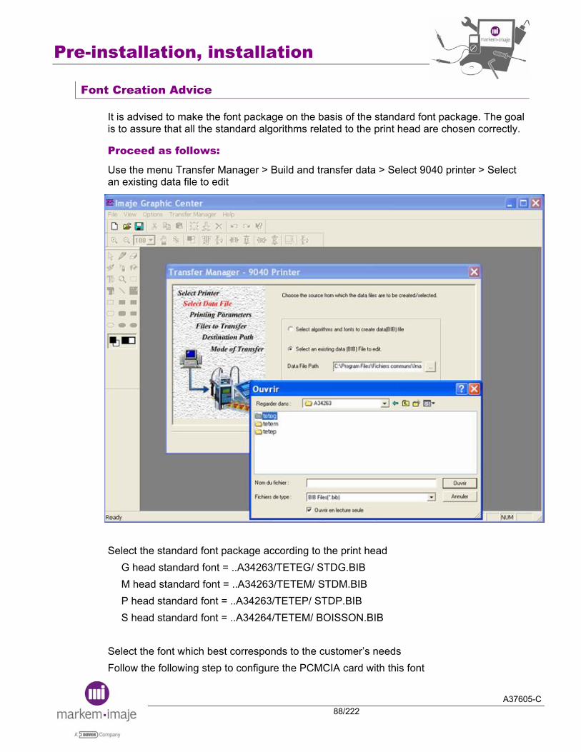
Font Creation Advice
It is advised to make the font package on the basis of the standard font package. The goal is to assure that all the standard algorithms related to the print head are chosen correctly.
Proceed as follows:
Use the menu Transfer Manager > Build and transfer data > Select 9040 printer > Select an existing data file to edit Select the standard font package according to the print head
G head standard font = ..A34263/TETEG/ STDG.BIB M head standard font = ..A34263/TETEM/ STDM.BIB P head standard font = ..A34263/TETEP/ STDP.BIB S head standard font = ..A34264/TETEM/ BOISSON.BIB
Select the font which best corresponds to the customer’s needs Follow the following step to configure the PCMCIA card with this font

Pre-installation, installation
A37605-C89/222
Font download procedure
Proceed as follows:
Organize the files on the PCMCIA card’s root, such that all files lie in a directory. In this example, all the data generated in our previous step could be included in a folder called “FONT”. Insert the PCMCIA card in the PC board Go to the Preparation Menu > Initialisation > PCMCIA/USB/SD transfer:
• Select the folder “FONT” • Select “FONTS” as Data Type • Choose the menu “<== PCMCIA” to import the fonts into the printer Other tools menu
To access the configuration tool from the 9040 menu, press keys and simultaneously. The following screen will appear:
Pre-installation, installation
A37605-C90/222
If the “other tools” menu is selected, the following screen will appear:
The “Internal Disk Format” function deletes all the data from the disk, it is mandatory to have a tool card to recover the system after using this function.
The 9040 tool card will be created within the coming weeks. Its creation will be announced through a NTI.
Additional parameter in the Status/printhead
The Status/Printhead menu displays a new parameter to the right of the jet phase. This new parameter is related to the location of the break-off point. It has been added for production purpose only, and used to measure the production process’ consistency. There is no nominal value which could help to set the break-off point

Pre-installation, installation
A37605-C91/222
Notes:

Pre-installation, installation
A37605-C92/222
Notes:

A37605-C93/222
Troubleshooting

Troubleshooting
A37605-C94/222
Notes:

Troubleshooting
A37605-C95/222
■ Head faults A /D Description
Context Consequences
Check / Cause/ Remedy / Solution
Suction is present - Inhibit the recuperation fault. - Start-up the jet - Evaluate the rate of suction
If the suction is low The problem is hydraulic 1) pump 2) drop in in the recuperation tub 3) air inlet 4) output of the condensor If the suction is normal The problem is electronic 1) inside of the head dirty (open the rear cover) 2) wire in the umbilical 3) connections 4) quality of the ink 5) MAIN board
Recuperation
No suction 1) Motor/pump 2) Blocking 3) Gutter electrovalve blocked 4) Recuperation one way valve blocked 5) Tub or umbilical folded
Phase detection
1) Cleaning Clean the head, the cover and the inside of the head
2) Ink quality Dust, moisture, use-by date.
3) Electronics Break-off point (piezo, piezo board, MAIN board Charge signal (MAIN board) Detection signal (ADP board, MAIN board,

Troubleshooting
A37605-C96/222
EHV Unwanted EHV
detected on the deflection plates by the printer. The printer detected an insulation fault on the EHV lines during operation (current leak of more than 10µA).
1) Cleanliness of deflection plates Cleaning with soapy water and letting dry may solve the problem.
2) Cleanliness inside head Open the rear cover Clean away any traces of ink
3) EHV block 4) MAIN board
EHV The printer detected:- unwanted EHV on the deflection plates - a current leak of more than 10µA
Disconnect the EHV cables in the electronic compartment and acquit the fault: - The fault persists: Its origin is in the cabinet
MAIN board Connections EHV block
-The fault does not persist: Its origin is in the print module
Deflection plates (Cleaning with soapy water and letting dry may solve the problem) External electrostatic perturbations Internal parts of the head damaged or dirty
Cover missing Check:
- MAIN board - connections and conduits (Black/white & green)

Troubleshooting
A37605-C97/222
■ Ink circuit faults A /D Description
Context Consequences
Check / Cause/ Remedy / Solution
Viscosity Draining or filling of the viscometer > 90s
Check all the elements of the viscosity measurement circuit (ELV, calibrated leak, calibrated tube, connections, MAIN board, … ). Check the safety level blocks Check the conductivity of the ink
Ink level low
Check the electrodes (dry ink), the ELV and the connections Check the safety level blocks Check the conductivity of the ink Check the MAIN board
Additive level low
Solvent fault
NEW: This fault appears after two fillings of the viscometer without additive.
Check the ELV and the connections Check the safety level blocks Check the conductivity of the ink Check the MAIN board
Caution: If the printer is stopped when the “Solvent fault” is active, there is no “Active Stanby”.
Incorrect pressure
P < 2,4bars: Connections Ink too much fluid Pump used P > 3,6 bars (5.5 bars on P head):
The circuit is partially blocked after the main filter (head filter, tube folded in the umbilical or in the head, …)
Caution: Always wait 15 seconds minimum between the “Stop” and the “Restart” of the printer (requisite time to put the pressure circuit to the atmospheric pressure.
Troubleshooting
A37605-C98/222
■ General faults Printing speed This alarm appears
after printing to indicate that the tachometer speed (after division) is too high for the algo. used in the message.
Check the message parameters, the algo. and the resolution mainly if the message is send by V24.
Internal serial link
Fan / Compressed air
Compressed air on IP65 only, fan on all other versions.
Check: - the rotation of the fan or the presence of the compressed air. - the presence of 24V - the MAIN board - the connections
Caution: The fault is managed during the “veille active”.
Temperature The electronic
compartment temperature > 70 °C
Check: - the presence of 15V on the power supply board - the connections - the MAIN board
CPU - IMP communication Communication stopped on port 2 or 4. Only on S8C2 and S8C2 China
The fault occurs after the conveyor has been stopped for a long time during message printing The fault persist after attempting to print the message at constant speed.
Restart printing The connection between the PC board and the MAIN board is faulty. The MAIN board is faulty
Memory lost
Check the position of the jumper …. Lithium battery (voltage < 3V)

Troubleshooting
A37605-C99/222
CPU faulty
Unknown gene. n°
Ensure that the fonts contained in the message correspond to the fonts contained in the printer.

Troubleshooting
A37605-C100/222
Notes:

A37605-C101/222
After sales policy

After sales policy
A37605-C102/222
Notes:

After sales policy
A37605-C103/222
■ Time between services On the 4 different models of printers, 9040, 9040 IP65, 9040 S and S8C2, the lifetime is:
10 000 hrs for Vacuum pump 14 000 hrs for Pressure pump
Filter replacement:
Main filter must be replaced (refer to the printer manual and/or to the Ink Running Sheet) Head pressurization kit filter can be replaced (refer to the printer manual) The moulded head filter can be replaced (refer to the printer manual)
NOTE: The additive filter (for cannon flushing system) does not need to be replaced
Maintenance contracts
Two contracts are offered: STANDARD and ACCESS. (See details of these contracts on following pages)
After sales policy
A37605-C104/222
■ List of points to be checked during STANDARD maintenance agreement (9040, S8 C2, 9040 IP65, 9040S)
General information
Customer name: ______________________ Date : ____________________ Town : ______________________ Printer no. : ____________________ Contact name : ______________________ Visit report no. : ____________________ Contract no : ______________________ Service engineer : ____________________
Printer information
Type of printer: 9040 9040 IP65 9040 S S8 C2 Configuration: 1.1 1.2 2.1 2.2 Type of head: G M P Ink: ____________ Additive: _____________ Hours counter: ______________
Installation
Checked Accessory adjustment (cell, tacho., etc.) _________________________________ ___________________________________ Installation to Markem-Imaje specifications _________________________________ (temperature, console/head distance) ___________________________________ Printer connected to suitable power supply _________________________________ and correctly grounded ___________________________________ No vibrations on head(s) _________________________________ ___________________________________ Head/object distance as specified _________________________________ ___________________________________ Position of umbilical (no vibrations, _________________________________ radius of curvature > 150 mm) ___________________________________ Correct grounding of cabinet, head and stand _________________________________ ___________________________________

After sales policy
A37605-C105/222
Operational check before maintenance
Checked Comments Visual inspection of all wiring and ___________________________________ ribbon cables (machine OFF) _____________________________________ Check connection of the Peltier ___________________________________ condenser _____________________________________ Check Peltier condenser fan rotation ___________________________________
_____________________________________ Check cleanness of fan guard (grid) ___________________________________
_____________________________________ Check rotation of main fan (flow of ___________________________________ air from top to bottom) _____________________________________ General appearance of ink circuit ___________________________________ (no signs of damage, etc.) _____________________________________ Ink low level (disconnect a probe on ___________________________________ ink reservoir) _____________________________________ Checked Comments Head 1 Head 2 Print module visual appearance _____________________________ Head electrovalves operate correctly _____________________________ Jet stable and centred _____________________________ Break-off point setting _____________________________ Pressure: ________ Viscosity:_______ Vm:__________
MANUAL PRINT TEST SAMPLE (or comments in case the printer does not function properly)

After sales policy
A37605-C106/222
Ink circuit flushing session
Completed Comments Drain the ink circuit and check cleanliness _________________________________ of grid filter in ink and additive tanks ___________________________________ Flush ink circuit using the flushing tool _________________________________
___________________________________
Parts replaced
Ink Filter Part Main location Comments Part number: - ENM5934 - ENM37176 for ink 5151 Main location: Ink circuit Replacement: - 1 year or 3 600 Hrs - 2 000 Hrs for ink 5151
Quantity: 1
Part replaced
Head filter 14µ Part Main location Comments Part number: ENM34410 Main location: Printing module Replacement: - 1 year or 3 600 Hrs - 2 000 Hrs for ink 5151
Quantity: 1per head
Cabinet, hydraulic
compartment
Part replaced

After sales policy
A37605-C107/222
Filter(s) for pressurization kit
Part Main location Comments
Part number: ENM20498
Main location: Air treatment unit in the hydraulic compartment Replacement: 12 months * * could be 6 months according to the quality of the air Quantity: 1
Part replaced
Vacuum pump(s) Part Main location Comments
Part number: - ENM4295 - ENM16891 for inks 5117
and 5127 Main location: Ink circuit Replacement: - 10 000 Hrs - 6 000 Hrs for inks 5117
and 5127 Quantity: 1per head
(S8 C2 , 9040 )
Part replaced
Pressure pump(s) Part Main location Comments Part number: - ENM5629 (G & M-head) - ENM18221 (P-head) Main location: Ink circuit Replacement: - 14 000 Hrs - 8 000Hrs for inks 5117
and 5127 Quantity: 1
(S8 C2 , 9040)
Part replaced

After sales policy
A37605-C108/222
Checking pumps
Completed Comments Pump pressure > 3.5 bar at 1,500 rpm _________________________________ (motor speed locked, use by-pass for test). (If not, recommended replacement of pump) Nominal values are 1500rpm +/- 50rpm (1.4 head: 1800rpm,P head:2500rpm) Pump 1 vacuum level > 0.6 bar and at stable _________________________________ level (visco ELV closed) Pump 2 vacuum level > 0.6 bar _________________________________ and at stable level
Parts replaced (other than those included in the maintenance agreement)
Yes No Parts replacement Part number Description Comments __________ ___________________________ _____________________________ __________ ___________________________ _____________________________ __________ ___________________________ _____________________________ __________ ___________________________ _____________________________
After sales policy
A37605-C109/222
Operational test after maintenance
OK Not OK Comments Cover fault _________________________________________ Recuperation fault _________________________________________ EHT fault _________________________________________ Jet stable and centered _________________________________________ Break-off point setting _________________________________________ Pressure: ________ Viscosity:_______ Vm:__________ MANUAL PRINT TEST SAMPLE

After sales policy
A37605-C110/222
User
Yes No Comments The user knows the safety rules _______________________
_______________________ Printer documentation is available _______________________
_______________________ The user knows basic maintenance _______________________ procedures _______________________ The user knows how to use the operator _______________________ Interface _______________________ The user needs training _______________________
_______________________

After sales policy
A37605-C111/222
Maintenance report
Yes No Comments Maintenance complete ___________________________________ ___________________________________ ___________________________________ ___________________________________ ___________________________________
Action to be taken by Markem-Imaje by __ / __ / __ Service engineer Name: Signature:
Action to be taken by customer by ___ / ___ / ___ Customer Name: Signature:
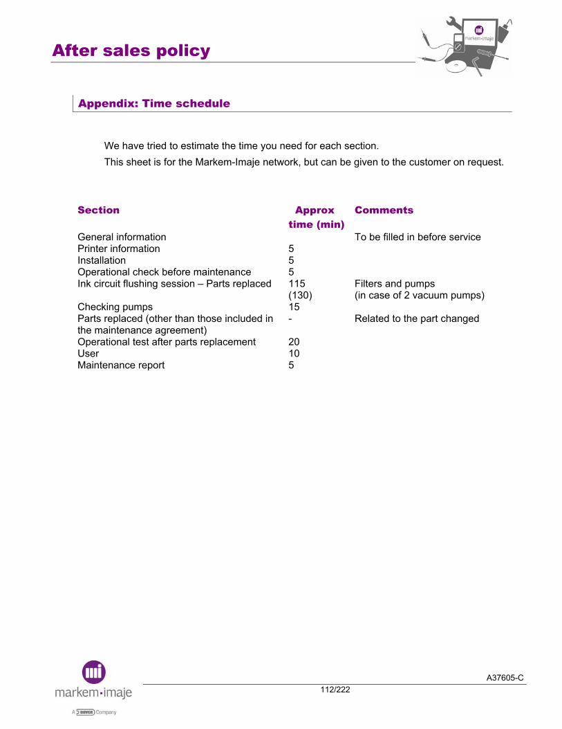
After sales policy
A37605-C112/222
Appendix: Time schedule
We have tried to estimate the time you need for each section. This sheet is for the Markem-Imaje network, but can be given to the customer on request.
Section Approx time (min)
Comments
General information Printer information Installation Operational check before maintenance Ink circuit flushing session – Parts replaced Checking pumps Parts replaced (other than those included in the maintenance agreement) Operational test after parts replacement User Maintenance report
5 5 5 115 (130) 15 - 20 10 5
To be filled in before service Filters and pumps (in case of 2 vacuum pumps) Related to the part changed

After sales policy
A37605-C113/222

After sales policy
A37605-C114/222
■ List of points to be checked during ACCESS maintenance agreement (9040, S8 C2, 9040 IP65, 9040S)
General information
Customer name: ______________________ Date : ____________________ Town : ______________________ Printer no. : ____________________ Contact name : ______________________ Visit report no. : ____________________ Contract no : ______________________ Service engineer : ____________________
Printer information
Type of printer: 9040 9040 IP65 9040 S S8 C2 Configuration: 1.1 1.2 2.1 2.2 Type of head: G M P Ink: ____________ Additive: _____________ Hours counter: ____________
Installation
Checked Accessory adjustment (cell, tacho., etc.) _________________________________ ___________________________________ Installation to MARKEM-IMAJE specifications _________________________________ (temperature, console/head distance) ___________________________________ Printer connected to suitable power supply _________________________________ and correctly grounded ___________________________________ No vibrations on head(s) _________________________________ ___________________________________ Head/object distance as specified _________________________________ ___________________________________ Position of umbilical (no vibrations, _________________________________ radius of curvature > 150 mm) ___________________________________ Correct grounding of cabinet, head and stand _________________________________ ___________________________________

After sales policy
A37605-C115/222
Operational check before maintenance
Checked Comments Visual inspection of all wiring and ___________________________________ ribbon cables (machine OFF) _____________________________________ Check connection of the Peltier ___________________________________ condenser _____________________________________ Check Peltier condenser fan rotation ___________________________________
_____________________________________ Check cleanness of fan guard (grid) ___________________________________
_____________________________________ Check rotation of main fan (flow of ___________________________________ air from top to bottom) _____________________________________ General appearance of ink circuit ___________________________________ (no signs of damage, etc.) _____________________________________ Ink low level (disconnect a probe on ___________________________________ ink reservoir) _____________________________________ Checked Comments Head 1 Head 2 Print module visual appearance _____________________________ Head electro valves operate correctly _____________________________ Jet stable and centered _____________________________ Break-off point setting _____________________________ Pressure: ________ Viscosity:_______ Vm:__________
MANUAL PRINT TEST SAMPLE (or comments in case the printer does not function properly)
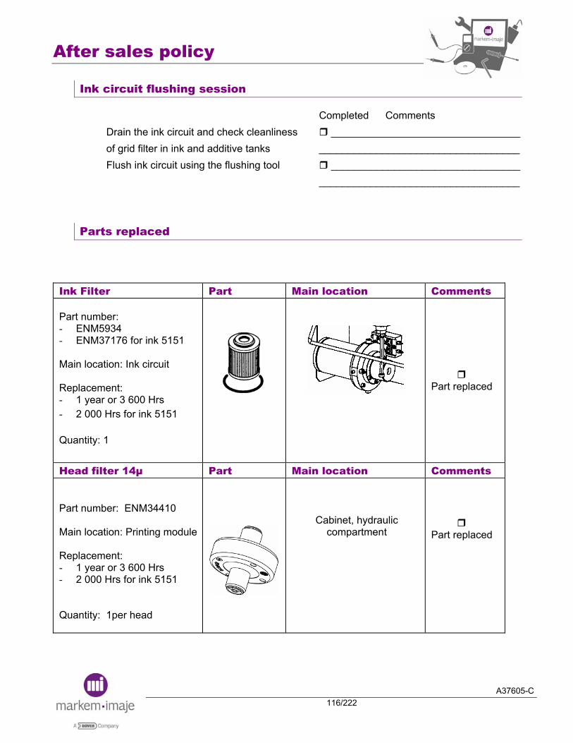
After sales policy
A37605-C116/222
Ink circuit flushing session
Completed Comments Drain the ink circuit and check cleanliness _________________________________ of grid filter in ink and additive tanks ___________________________________ Flush ink circuit using the flushing tool _________________________________
___________________________________
Parts replaced
Ink Filter Part Main location Comments Part number: - ENM5934 - ENM37176 for ink 5151 Main location: Ink circuit Replacement: - 1 year or 3 600 Hrs - 2 000 Hrs for ink 5151 Quantity: 1
Part replaced
Head filter 14µ Part Main location Comments Part number: ENM34410 Main location: Printing module Replacement: - 1 year or 3 600 Hrs - 2 000 Hrs for ink 5151
Quantity: 1per head
Cabinet, hydraulic compartment
Part replaced

After sales policy
A37605-C117/222
Filter(s) for pressurization kit Part Main location Comments Part number: ENM20498 Main location: Air treatment unit in the hydraulic compartment Replacement: 12 months * * could be 6 months according to the quality of the air Quantity: 1
Part replaced
Checking pumps
Completed Comments Pump pressure > 3.5 bar at 1,500 rpm _________________________________ (motor speed locked, use by-pass for test). (If not, recommended replacement of pump) Nominal values are 1500rpm +/- 50rpm (1.4 head: 1800rpm,P head:2500rpm) Pump 1 vacuum level > 0.6 bar and at stable _________________________________ level (visco ELV closed) Pump 2 vacuum level > 0.6 bar _________________________________ and at stable level
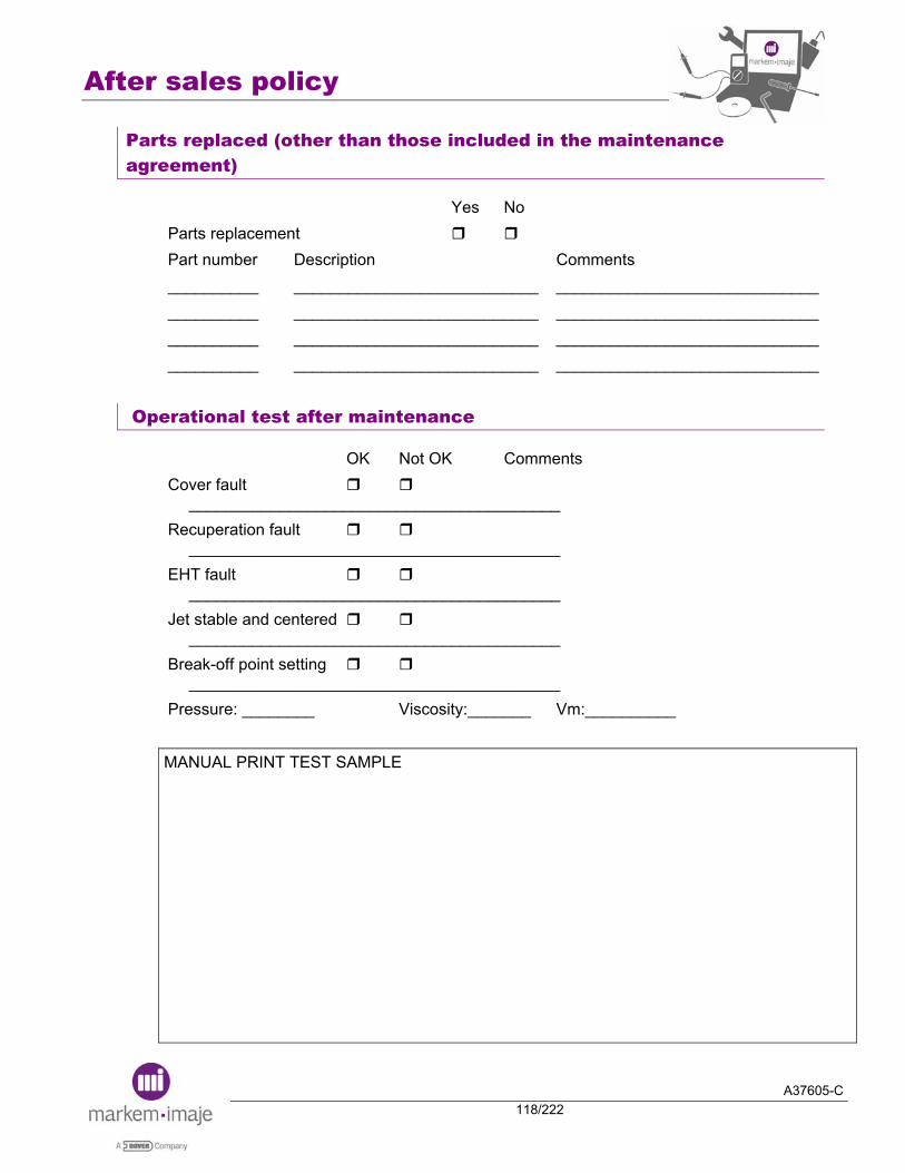
After sales policy
A37605-C118/222
Parts replaced (other than those included in the maintenance agreement)
Yes No Parts replacement Part number Description Comments __________ ___________________________ _____________________________ __________ ___________________________ _____________________________ __________ ___________________________ _____________________________ __________ ___________________________ _____________________________
Operational test after maintenance
OK Not OK Comments Cover fault _________________________________________ Recuperation fault _________________________________________ EHT fault _________________________________________ Jet stable and centered _________________________________________ Break-off point setting _________________________________________ Pressure: ________ Viscosity:_______ Vm:__________ MANUAL PRINT TEST SAMPLE
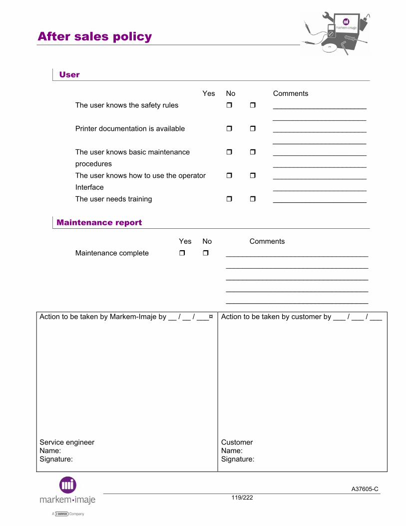
After sales policy
A37605-C119/222
User
Yes No Comments The user knows the safety rules _______________________
_______________________ Printer documentation is available _______________________
_______________________ The user knows basic maintenance _______________________ procedures _______________________ The user knows how to use the operator _______________________ Interface _______________________ The user needs training _______________________
Maintenance report
Yes No Comments Maintenance complete ___________________________________ ___________________________________ ___________________________________ ___________________________________ ___________________________________
Action to be taken by Markem-Imaje by __ / __ / ___¤
Service engineer Name: Signature:
Action to be taken by customer by ___ / ___ / ___
Customer Name: Signature:

After sales policy
A37605-C120/222
Appendix: Time schedule
We have tried to estimate the time you need for each section. This sheet is for the Markem-Imaje network, but can be given to the customer on request.
Section Approx time (min)
Comments
General information Printer information Installation Operational check before maintenance Ink circuit flushing session – Parts replaced Checking pumps Parts replaced (other than those included in the maintenance agreement) Operational test after parts replacement User Maintenance report
5 5 5
90 15
-
20 10
5
To be filled in before service Filters Related to the part changed
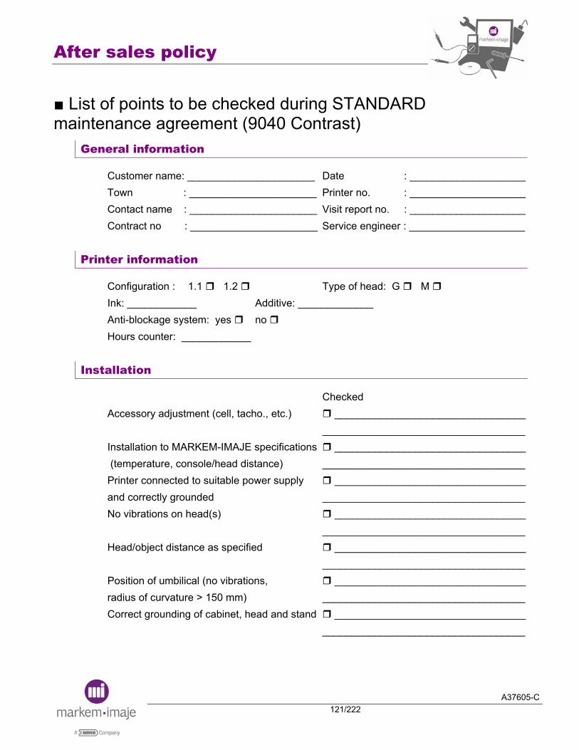
After sales policy
A37605-C121/222
■ List of points to be checked during STANDARD maintenance agreement (9040 Contrast)
General information
Customer name: ______________________ Date : ____________________ Town : ______________________ Printer no. : ____________________ Contact name : ______________________ Visit report no. : ____________________ Contract no : ______________________ Service engineer : ____________________
Printer information
Configuration : 1.1 1.2 Type of head: G M Ink: ____________ Additive: _____________ Anti-blockage system: yes no Hours counter: ____________
Installation
Checked Accessory adjustment (cell, tacho., etc.) _________________________________ ___________________________________ Installation to MARKEM-IMAJE specifications _________________________________ (temperature, console/head distance) ___________________________________ Printer connected to suitable power supply _________________________________ and correctly grounded ___________________________________ No vibrations on head(s) _________________________________ ___________________________________ Head/object distance as specified _________________________________ ___________________________________ Position of umbilical (no vibrations, _________________________________ radius of curvature > 150 mm) ___________________________________ Correct grounding of cabinet, head and stand _________________________________ ___________________________________
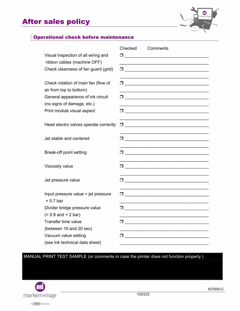
After sales policy
A37605-C122/222
Operational check before maintenance
Checked Comments Visual inspection of all wiring and ___________________________________ ribbon cables (machine OFF) _____________________________________ Check cleanness of fan guard (grid) ___________________________________ _____________________________________ Check rotation of main fan (flow of ___________________________________ air from top to bottom) _____________________________________ General appearance of ink circuit ___________________________________ (no signs of damage, etc.) _____________________________________ Print module visual aspect ___________________________________
_____________________________________ Head electro valves operate correctly ___________________________________ _____________________________________ Jet stable and centered ___________________________________ _____________________________________ Break-off point setting ___________________________________ _____________________________________ Viscosity value ___________________________________ _____________________________________ Jet pressure value ___________________________________ _____________________________________ Input pressure value = jet pressure ___________________________________ + 0.7 bar _____________________________________ Divider bridge pressure value ___________________________________ (> 0.8 and < 2 bar) _____________________________________ Transfer time value ___________________________________ (between 10 and 20 sec) _____________________________________ Vacuum value setting ___________________________________ (see Ink technical data sheet) _____________________________________
MANUAL PRINT TEST SAMPLE (or comments in case the printer does not function properly )
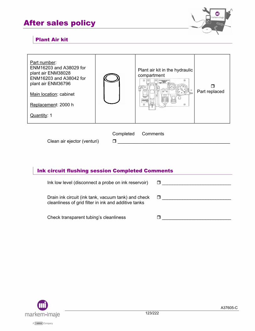
After sales policy
A37605-C123/222
Plant Air kit
Part number: ENM16203 and A38029 for plant air ENM38028 ENM16203 and A38042 for plant air ENM36796 Main location: cabinet Replacement: 2000 h Quantity: 1
Plant air kit in the hydraulic compartment
Part replaced
Completed Comments Clean air ejector (venturi) ____________________________________________
Ink circuit flushing session Completed Comments
Ink low level (disconnect a probe on ink reservoir) ___________________________ Drain ink circuit (ink tank, vacuum tank) and check ___________________________ cleanliness of grid filter in ink and additive tanks Check transparent tubing’s cleanliness ___________________________
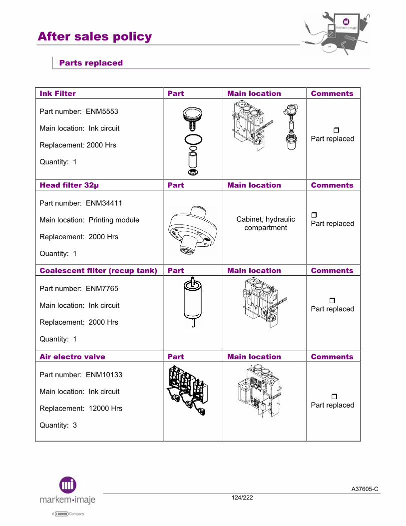
After sales policy
A37605-C124/222
Parts replaced
Ink Filter Part Main location Comments Part number: ENM5553 Main location: Ink circuit Replacement: 2000 Hrs Quantity: 1
Part replaced
Head filter 32µ Part Main location Comments Part number: ENM34411 Main location: Printing module Replacement: 2000 Hrs Quantity: 1
Cabinet, hydraulic compartment
Part replaced
Coalescent filter (recup tank) Part Main location Comments Part number: ENM7765 Main location: Ink circuit Replacement: 2000 Hrs Quantity: 1
Part replaced
Air electro valve Part Main location Comments Part number: ENM10133 Main location: Ink circuit Replacement: 12000 Hrs Quantity: 3
Part replaced

After sales policy
A37605-C125/222
Ink electro valve Part Main location Comments Part number: ENM10133 Main location: Ink circuit Replacement: 16000 Hrs Quantity: 2
Part replaced
Coalescent filters (visco/accu/input)
Part Main location Comments
Part number: ENM7765 Main location: Ink circuit Replacement: 6000 Hrs Quantity: 2 or 3
Part replaced
Stirring bar Part Main location Comments Part number: ENM11428 Main location: Ink circuit Replacement: 1 year Quantity: 1
Part replaced
Ink reservoir Part Main location Comments Part number: ENM6246 Main location: Ink circuit Replacement: 3 years Quantity: 1
Part replaced

After sales policy
A37605-C126/222
Parts replaced (other than those included in the maintenance agreement)
Yes No Parts replacement Part number Description Comments __________ ____________________________ _____________________________ __________ ____________________________ _____________________________ __________ ____________________________ _____________________________ __________ ____________________________ _____________________________
Operational test after maintenance
Checked Comments Cover fault ______________________________________
________________________________________ Recuperation fault ______________________________________
________________________________________ EHT fault ______________________________________
________________________________________ Jet stable and centered ______________________________________
________________________________________ Break-off point setting ______________________________________
________________________________________ General appearance of ink circuit ______________________________________ (no signs of damage, etc.) ________________________________________ Viscosity value ______________________________________
________________________________________ Jet pressure value ______________________________________
________________________________________ Input pressure value = jet ______________________________________ pressure + 0.7 bar ________________________________________ Divider bridge pressure ______________________________________ value (> 0.8 and < 2 bar) ________________________________________

After sales policy
A37605-C127/222
Transfer time value ______________________________________ (between 10 and 20 sec) ________________________________________ Vacuum value setting (see Ink technical data sheet) ______________________________________
MANUAL PRINT TEST SAMPLE
User
Yes No Comments The user knows the safety rules _____________________________ Printer documentation is available _____________________________ The user knows basic maintenance _____________________________ procedures The user knows how to use _____________________________ the operator interface The user needs training _____________________________
Maintenance report
Yes No Comments Maintenance complete _____________________________ _____________________________ _____________________________ _____________________________ _____________________________

After sales policy
A37605-C128/222
Action to be taken by Markem-Imaje by __ / __ / __
Service engineer Name: Signature:
Action to be taken by customer by ___ / ___ / ___
Customer Name: Signature:
Appendix: Time schedule
We have tried to estimate the time you need for each section. This sheet is for the Markem-Imaje network, but can be given to the customer on request.
Section Approx
time (min) Comments
General information Printer information Installation Operational check before maintenance Plant air kit Ink circuit flushing session – Parts replaced Parts replaced (other than those included in the maintenance agreement) Operational test after parts replacement User Maintenance report
5 5
10 30
150 -
15 5 5
To be filled in before service Filter and cleaning Filters and electro valves, cleaning Related to the part changed
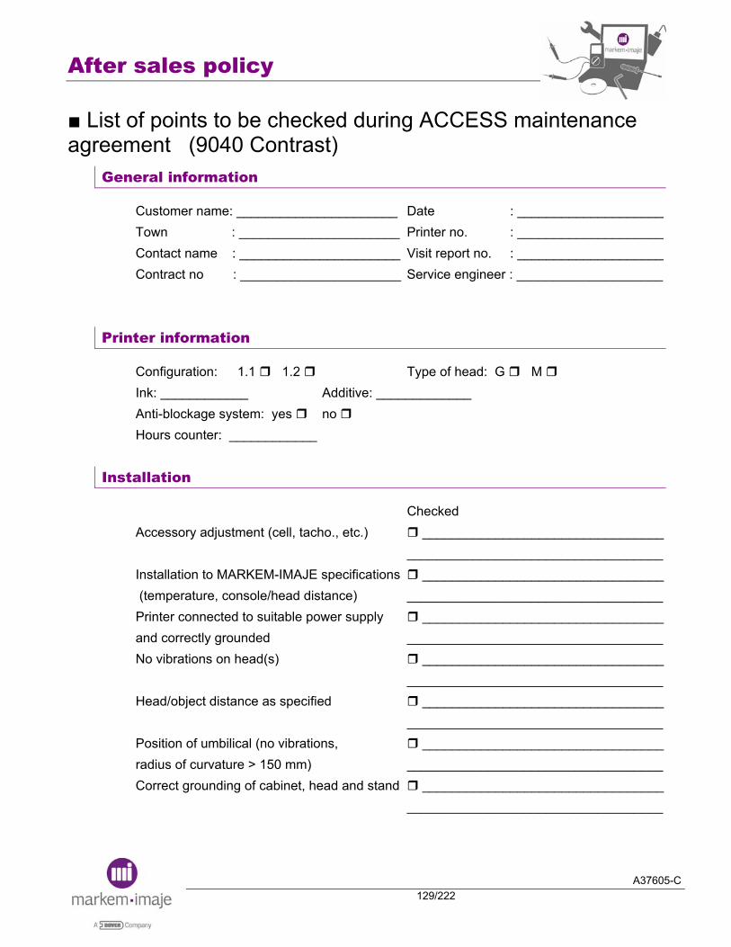
After sales policy
A37605-C129/222
■ List of points to be checked during ACCESS maintenance agreement (9040 Contrast)
General information
Customer name: ______________________ Date : ____________________ Town : ______________________ Printer no. : ____________________ Contact name : ______________________ Visit report no. : ____________________ Contract no : ______________________ Service engineer : ____________________
Printer information
Configuration: 1.1 1.2 Type of head: G M Ink: ____________ Additive: _____________ Anti-blockage system: yes no Hours counter: ____________
Installation
Checked Accessory adjustment (cell, tacho., etc.) _________________________________ ___________________________________
Installation to MARKEM-IMAJE specifications _________________________________ (temperature, console/head distance) ___________________________________
Printer connected to suitable power supply _________________________________ and correctly grounded ___________________________________ No vibrations on head(s) _________________________________ ___________________________________
Head/object distance as specified _________________________________ ___________________________________
Position of umbilical (no vibrations, _________________________________ radius of curvature > 150 mm) ___________________________________ Correct grounding of cabinet, head and stand _________________________________ ___________________________________

After sales policy
A37605-C130/222
Operational check before maintenance
Checked Comments Visual inspection of all wiring and ___________________________________ ribbon cables (machine OFF) _____________________________________ Check cleanness of fan guard (grid) ___________________________________ _____________________________________ Check rotation of main fan (flow of ___________________________________ air from top to bottom) _____________________________________ General appearance of ink circuit ___________________________________ (no signs of damage, etc.) _____________________________________ Print module visual aspect ___________________________________ _____________________________________ Head electro valves operate correctly ___________________________________ _____________________________________ Jet stable and centered ___________________________________ _____________________________________ Break-off point setting ___________________________________ _____________________________________ Viscosity value ___________________________________ _____________________________________ Jet pressure value ___________________________________ _____________________________________ Input pressure value = jet pressure ___________________________________ + 0.7 bar _____________________________________ Divider bridge pressure value ___________________________________ (> 0.8 and < 2 bar) _____________________________________ Transfer time value ___________________________________ (between 10 and 20 sec) _____________________________________ Vacuum value setting ___________________________________ (see Ink technical data sheet) _____________________________________
MANUAL PRINT TEST SAMPLE (or comments in case the printer does not function properly)

After sales policy
A37605-C131/222
Plant Air kit
Part number: ENM16203 and A38029 for plant air ENM38028 ENM16203 and A38042 for plant air ENM36796 Main location: cabinet Replacement: 2000 Hrs Quantity: 1
Plant air kit in the hydraulic compartment
Part replaced
Completed Comments Clean air ejector (venturi) ____________________________________________
Ink circuit flushing session Completed Comments
Ink low level (disconnect a probe on ink reservoir) ___________________________ Drain ink circuit (ink tank, vacuum tank) and check ___________________________ cleanliness of grid filter in ink and additive tanks Check transparent tubing’s cleanliness ___________________________

After sales policy
A37605-C132/222
Parts replaced
Ink Filter Part Main location Comments Part number: ENM5553 Main location: Ink circuit Replacement: 2000 Hrs Quantity: 1
Part replaced
Head filter 32µ Part Main location Comments Part number: ENM34411 Main location: Printing module Replacement: 2000 Hrs Quantity: 1
Cabinet, hydraulic compartment
Part replaced
Coalescent filter (recup tank) Part Main location Comments Part number: ENM7765 Main location: Ink circuit Replacement: 2000 Hrs Quantity: 1
Part replaced
Parts replaced (other than those included in the maintenance agreement)
Yes No Parts replacement Part number Description Comments __________ ____________________________ _____________________________ __________ ____________________________ _____________________________ __________ ____________________________ _____________________________ __________ ____________________________ _____________________________
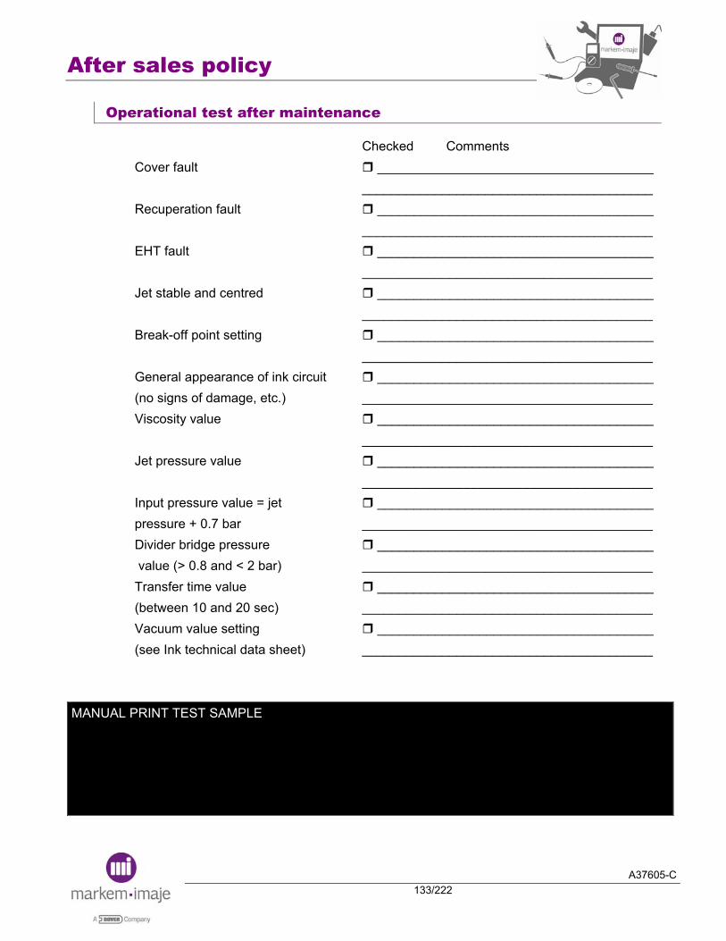
After sales policy
A37605-C133/222
Operational test after maintenance
Checked Comments Cover fault ______________________________________
________________________________________ Recuperation fault ______________________________________
________________________________________ EHT fault ______________________________________
________________________________________ Jet stable and centred ______________________________________
________________________________________ Break-off point setting ______________________________________
________________________________________ General appearance of ink circuit ______________________________________ (no signs of damage, etc.) ________________________________________ Viscosity value ______________________________________
________________________________________ Jet pressure value ______________________________________
________________________________________ Input pressure value = jet ______________________________________ pressure + 0.7 bar ________________________________________ Divider bridge pressure ______________________________________ value (> 0.8 and < 2 bar) ________________________________________ Transfer time value ______________________________________ (between 10 and 20 sec) ________________________________________ Vacuum value setting ______________________________________ (see Ink technical data sheet) ________________________________________
MANUAL PRINT TEST SAMPLE
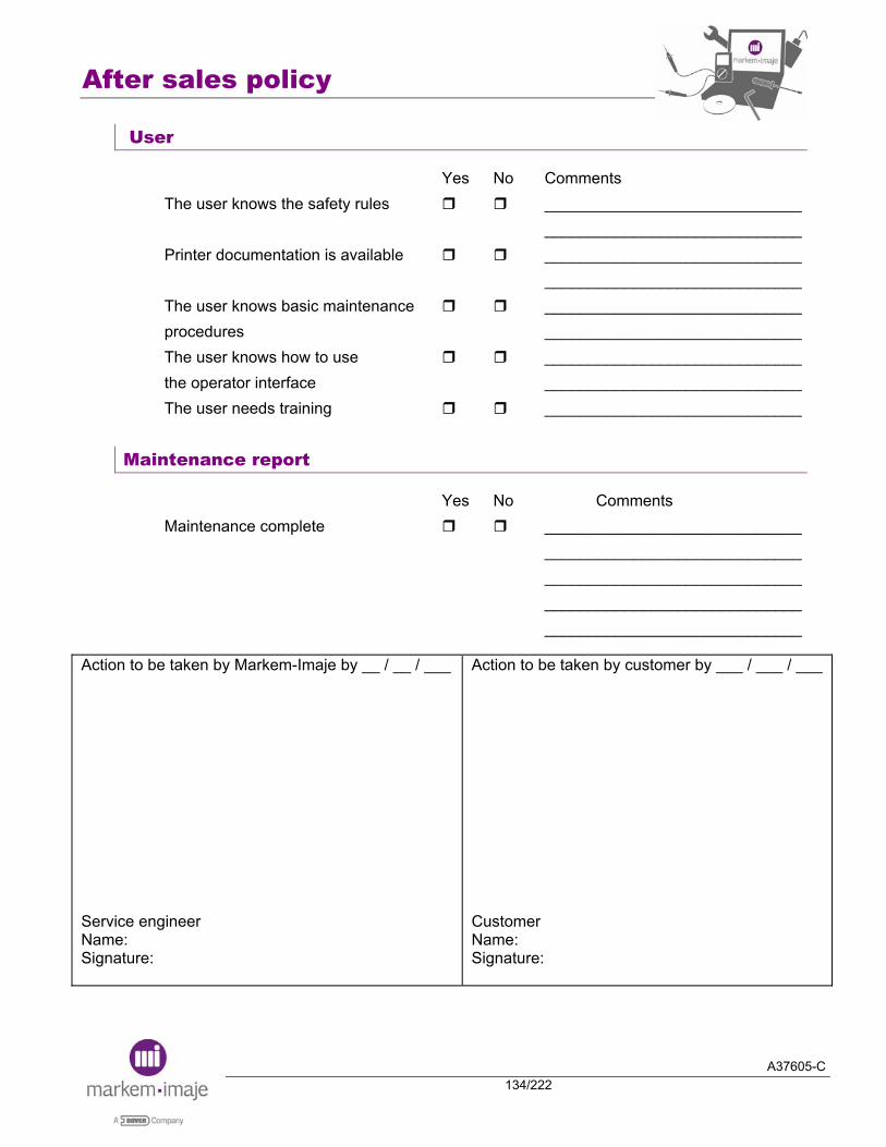
After sales policy
A37605-C134/222
User
Yes No Comments The user knows the safety rules _____________________________ _____________________________ Printer documentation is available _____________________________
_____________________________ The user knows basic maintenance _____________________________ procedures _____________________________ The user knows how to use _____________________________ the operator interface _____________________________ The user needs training _____________________________
Maintenance report
Yes No Comments Maintenance complete _____________________________ _____________________________ _____________________________ _____________________________ _____________________________
Action to be taken by Markem-Imaje by __ / __ / ___ Service engineer Name: Signature:
Action to be taken by customer by ___ / ___ / ___ Customer Name: Signature:
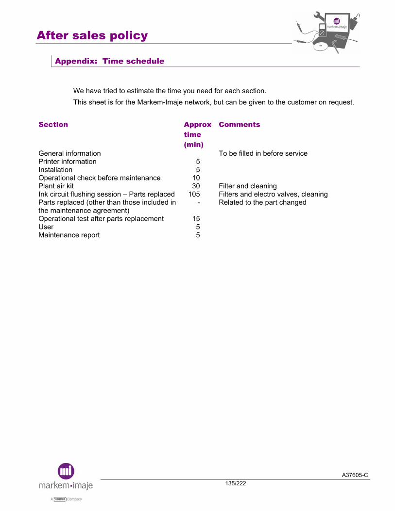
After sales policy
A37605-C135/222
Appendix: Time schedule
We have tried to estimate the time you need for each section. This sheet is for the Markem-Imaje network, but can be given to the customer on request.
Section Approx time (min)
Comments
General information Printer information Installation Operational check before maintenance Plant air kit Ink circuit flushing session – Parts replaced Parts replaced (other than those included in the maintenance agreement) Operational test after parts replacement User Maintenance report
5 5
10 30
105 -
15 5 5
To be filled in before service Filter and cleaning Filters and electro valves, cleaningRelated to the part changed
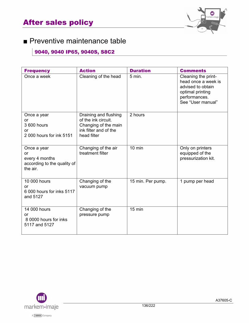
After sales policy
A37605-C136/222
■ Preventive maintenance table 9040, 9040 IP65, 9040S, S8C2
Frequency Action Duration Comments Once a week Cleaning of the head 5 min. Cleaning the print-
head once a week is advised to obtain optimal printing performances. See “User manual”
Once a year or 3 600 hours or 2 000 hours for ink 5151
Draining and flushing of the ink circuit. Changing of the main ink filter and of the head filter
2 hours
Once a year or every 4 months according to the quality of the air.
Changing of the air treatment filter
10 min Only on printers equipped of the pressurization kit.
10 000 hours or 6 000 hours for inks 5117 and 5127
Changing of the vacuum pump
15 min. Per pump. 1 pump per head
14 000 hours or 8 0000 hours for inks 5117 and 5127
Changing of the pressure pump
15 min
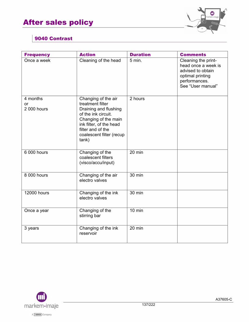
After sales policy
A37605-C137/222
9040 Contrast
Frequency Action Duration Comments Once a week Cleaning of the head 5 min. Cleaning the print-
head once a week is advised to obtain optimal printing performances. See “User manual”
4 months or 2 000 hours
Changing of the air treatment filter Draining and flushing of the ink circuit. Changing of the main ink filter, of the head filter and of the coalescent filter (recup tank)
2 hours
6 000 hours Changing of the coalescent filters (visco/accu/input)
20 min
8 000 hours Changing of the air electro valves
30 min
12000 hours Changing of the ink electro valves
30 min
Once a year Changing of the stirring bar
10 min
3 years Changing of the ink reservoir
20 min

After sales policy
A37605-C138/222
Notes:

A37605-C139/222
Electronics

Electronics
A37605-C140/222
Notes:
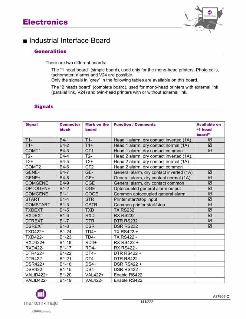
Electronics
A37605-C141/222
■ Industrial Interface Board Generalities
There are two different boards: The “1 head board” (simple board), used only for the mono-head printers. Photo cells, tachometer, alarms and V24 are possible. Only the signals in “grey” in the following tables are available on this board. The “2 heads board” (complete board), used for mono-head printers with external link (parallel link, V24) and twin-head printers with or without external link.
Signals
Signal Connector
block Mark on the board
Function / Comments Available on “1 head board”
T1- B4-1 T1- Head 1 alarm, dry contact inverted (1A) T1+ B4-2 T1+ Head 1 alarm, dry contact normal (1A) COMT1 B4-3 CT1 Head 1 alarm, dry contact common T2- B4-4 T2- Head 2 alarm, dry contact inverted (1A). T2+ B4-5 T2+ Head 2 alarm, dry contact normal (1A) COMT2 B4-6 CT2 Head 2 alarm, dry contact common GENE- B4-7 GE- General alarm, dry contact inverted (1A) GENE+ B4-8 GE+ General alarm, dry contact normal (1A) COMGENE B4-9 CGE General alarm, dry contact common OPTOGENE B1-2 OGE Optocoupled general alarm output COMGENE B1-1 COGE Common optocoupled general alarm START B1-4 STR Printer start/stop input COMSTART B1-3 CSTR Common printer start/stop TXDEXT B1-5 TXD TX RS232 RXDEXT B1-6 RXD RX RS232 DTREXT B1-7 DTR DTR RS232 DSREXT B1-8 DSR DSR RS232 TXD422+ B1-24 TD4+ TX RS422 + TXD422- B1-23 TD4- TX RS422 - RXD422+ B1-18 RD4+ RX RS422 + RXD422- B1-17 RD4- RX RS422 - DTR422+ B1-22 DT4+ DTR RS422 + DTR422- B1-21 DT4- DTR RS422 - DSR422+ B1-16 DS4+ DSR RS422 + DSR422- B1-15 DS4- DSR RS422 - VALID422+ B1-20 VAL422+ Enable RS422 VALID422- B1-19 VAL422- Enable RS422

Electronics
A37605-C142/222
Signal Connector
block Mark on the board
Function / Comments Available on “1 head board”
OUT1 B1-10 OT1 Not use COMOUT1 B1-9 COT1 Not use IN1 B1-12 IN1 Not use COMIN1 B1-11 CIN1 Not use GND B1-
13/14/25 GND
only B1-13/14
+5V B1-26 +5V +15V B1-27 +15V -15V B1-28 -15V DTOP1 B2-4 TOP1 Photo cell head 1 input. Positive pin. COMDTOP1 B2-3 CTP1 Photo cell head 1 input. Negative pin. VALIMP1 B2-6 VAL1 Validation input head 1. Positive pin. COMVALIMP1 B2-5 CVAL1 Validation input head 1. Negative pin. TACHY1 B2-8 TAC1 Tacho coder input. Positive pin. COMTACHY1 B2-7 CTC1 Tacho coder input. Negative pin. RAZC1 B2-10 RAZ1 COMRAZC1 B2-9 CRZ1
Head 1 reset counter 1 input
INCC1 B2-12 IC1 COMINCC1 B2-11 CIC1
Head 1 increment counter 1 input
STOPI1 B2-14 STO1 COMSTOPI1 B2-13 CTO1
Stop printing head 1 input
SPROGI1 B2-16 SPR1 Complete printing output. Positive pin. COMSPROG1 B2-15 CSP1 Complete printing output. Negative pin. VALFINI1 B2-18 FIN1 COMVALFIN1 B2-17 CFN1
Final value of the counter output
OPTOT1 B2-20 OPT1 Optocoupled head 1 alarm output. Positive pin.
COMOPTOT1 B2-19 COT1 Optocoupled head 1 alarm output. Negative pin.
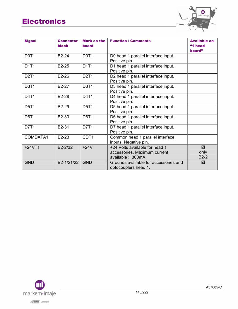
Electronics
A37605-C143/222
Signal Connector
block Mark on the board
Function / Comments Available on “1 head board”
D0T1 B2-24 D0T1 D0 head 1 parallel interface input. Positive pin.
D1T1 B2-25 D1T1 D1 head 1 parallel interface input. Positive pin.
D2T1 B2-26 D2T1 D2 head 1 parallel interface input. Positive pin.
D3T1 B2-27 D3T1 D3 head 1 parallel interface input. Positive pin.
D4T1 B2-28 D4T1 D4 head 1 parallel interface input. Positive pin.
D5T1 B2-29 D5T1 D5 head 1 parallel interface input. Positive pin.
D6T1 B2-30 D6T1 D6 head 1 parallel interface input. Positive pin.
D7T1 B2-31 D7T1 D7 head 1 parallel interface input. Positive pin.
COMDATA1 B2-23 CDT1 Common head 1 parallel interface inputs. Negative pin.
+24VT1 B2-2/32 +24V +24 Volts available for head 1 accessories. Maximum current available : 300mA.
only B2-2
GND B2-1/21/22 GND Grounds available for accessories and optocouplers head 1.

Electronics
A37605-C144/222
Signal Connector
block Mark on the board
Function / Comments Available on “1 head board”
DTOP2 B3-4 TOP2 Photo cell head 2 input. Positive pin. COMDTOP2 B3-3 CTP2 Photo cell head 2 input. Negative pin. VALIMP2 B3-6 VAL2 Validation input head 2. Positive pin. COMVALIMP2 B3-5 CVAL2 Validation input head 2. Negative pin. TACHY2 B3-8 TAC2 Tacho coder input. Positive pin. COMTACHY2 B3-7 CTC2 Tacho coder input. Negative pin. RAZC2 B3-10 RAZ2 COMRAZC2 B3-9 CRZ2
Head 2 reset counter 1 input
INCC2 B3-12 IC2 COMINCC2 B3-11 CIC2
Head 2 increment counter 1 input
STOPI2 B3-14 STO2 COMSTOPI2 B3-13 CTO2
Stop printing head 2 input
SPROGI2 B3-16 SPR2 Complete printing output. Positive pin. COMSPROG2 B3-15 CSP2 Complete printing output. Negative pin. VALFINI2 B3-18 FIN2 COMVALFIN2 B3-17 CFN2
Final value of the counter output
OPTOT2 B3-20 OPT2 Optocoupled head 2 alarm output. Positive pin.
COMOPTOT2 B3-19 COT2 Optocoupled head 2 alarm output. Negative pin.
D0T2 B3-24 D0T2 D0 head 2 parallel interface input. Positive pin.
D1T2 B3-25 D1T2 D1 head 2 parallel interface input. Positive pin.
D2T2 B3-26 D2T2 D2 head 2 parallel interface input. Positive pin.
D3T2 B3-27 D3T2 D3 head 2 parallel interface input. Positive pin.
D4T2 B3-28 D4T2 D4 head 2 parallel interface input. Positive pin.
D5T2 B3-29 D5T2 D5 head 2 parallel interface input. Positive pin.
D6T2 B3-30 D6T2 D6 head 2 parallel interface input. Positive pin.
D7T2 B3-31 D7T2 D7 head 2 parallel interface input. Positive pin.
COMDATA2 B3-23 CDT2 Common head 2 parallel interface inputs. Negative pin.
+24VT2 B3-2/32 +24V +24 Volts available for head 2 accessories. Maximum current available: 300mA.
GND B3-1/21/22 GND Grounds available for accessories and optocouplers head 2.
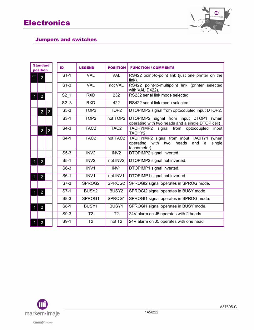
Electronics
A37605-C145/222
Jumpers and switches
Standard position
ID LEGEND POSITION FUNCTION / COMMENTS
1 2 S1-1 VAL VAL RS422 point-to-point link (just one printer on the link).
S1-3 VAL not VAL RS422 point-to-multipoint link (printer selected with VALID422).
1 2 S2_1 RXD 232 RS232 serial link mode selected
S2_3 RXD 422 RS422 serial link mode selected.
2 3 S3-3 TOP2 TOP2 DTOPIMP2 signal from optocoupled input DTOP2.
S3-1 TOP2 not TOP2 DTOPIMP2 signal from input DTOP1 (when operating with two heads and a single DTOP cell)
2 3 S4-3 TAC2 TAC2 TACHYIMP2 signal from optocoupled input TACHY2.
S4-1 TAC2 not TAC2 TACHYIMP2 signal from input TACHY1 (when
operating with two heads and a single tachometer).
S5-3 INV2 INV2 DTOPIMP2 signal inverted.
1 2 S5-1 INV2 not INV2 DTOPIMP2 signal not inverted.
S6-3 INV1 INV1 DTOPIMP1 signal inverted.
1 2 S6-1 INV1 not INV1 DTOPIMP1 signal not inverted.
S7-3 SPROG2 SPROG2 SPROGI2 signal operates in SPROG mode.
1 2 S7-1 BUSY2 BUSY2 SPROGI2 signal operates in BUSY mode.
S8-3 SPROG1 SPROG1 SPROGI1 signal operates in SPROG mode.
1 2
S8-1 BUSY1 BUSY1 SPROGI1 signal operates in BUSY mode.
S9-3 T2 T2 24V alarm on J5 operates with 2 heads
1 2 S9-1 T2 not T2 24V alarm on J5 operates with one head

Electronics
A37605-C146/222
Equipment:
LED 1
S 3
LED 2
LED 3
LED 4
LED 5
LED 6
LED 7
LED 8
LED 9
LED 10
LED 11
LED 12
LED 13
LED 14
LED 15
LED 16
LED 17
S1
S2
S 4
S 5
S 6
S 7
S 8
S 9
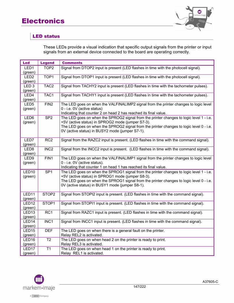
Electronics
A37605-C147/222
LED status
These LEDs provide a visual indication that specific output signals from the printer or input signals from an external device connected to the board are operating correctly.
Led Legend Comments LED1
(green) TOP2 Signal from DTOP2 input is present (LED flashes in time with the photocell signal).
LED2 (green)
TOP1 Signal from DTOP1 input is present (LED flashes in time with the photocell signal).
LED 3 (green)
TAC2 Signal from TACHY2 input is present (LED flashes in time with the tachometer pulses).
LED4 (green)
TAC1 Signal from TACHY1 input is present (LED flashes in time with the tachometer pulses).
LED5 (green)
FIN2 The LED goes on when the VALFINALIMP2 signal from the printer changes to logic level 0 - i.e. 0V (active status) Indicating that counter 2 on head 2 has reached its final value.
LED6 (green)
SP2 The LED goes on when the SPROG2 signal from the printer changes to logic level 1 - i.e. +5V (active status) in SPROG2 mode (jumper S7-3). The LED goes on when the SPROG2 signal from the printer changes to logic level 0 - i.e. 0V (active status) in BUSY2 mode (jumper S7-1).
LED7 (green)
RC2 Signal from the RAZC2 input is present. (LED flashes in time with the command signal).
LED8 (green)
INC2 Signal from the INCC2 input is present. (LED flashes in time with the command signal).
LED9 (green)
FIN1 The LED goes on when the VALFINALIMP1 signal from the printer changes to logic level 0 - i.e. 0V (active status). Indicating that counter 1 on head 1 has reached its final value.
LED10 (green)
SP1 The LED goes on when the SPROG1 signal from the printer changes to logic level 1 - i.e. +5V (active status) in SPROG1 mode (jumper S8-3). The LED goes on when the SPROG1 signal from the printer changes to logic level 0 - i.e. 0V (active status) in BUSY1 mode (jumper S8-1).
LED11 (green)
STOP2 Signal from STOPI2 input is present. (LED flashes in time with the command signal).
LED12 (green)
STOP1 Signal from STOPI1 input is present. (LED flashes in time with the command signal).
LED13 (green)
RC1 Signal from RAZC1 input is present. (LED flashes in time with the command signal).
LED14 (green)
INC1 Signal from INCC1 input is present. (LED flashes in time with the command signal).
LED15 (green)
DEF The LED goes on when there is a general fault on the printer. Relay REL2 is activated.
LED16 (green)
T2 The LED goes on when head 2 on the printer is ready to print. Relay REL3 is activated.
LED17 (green)
T1 The LED goes on when head 1 on the printer is ready to print. Relay REL1 is activated.
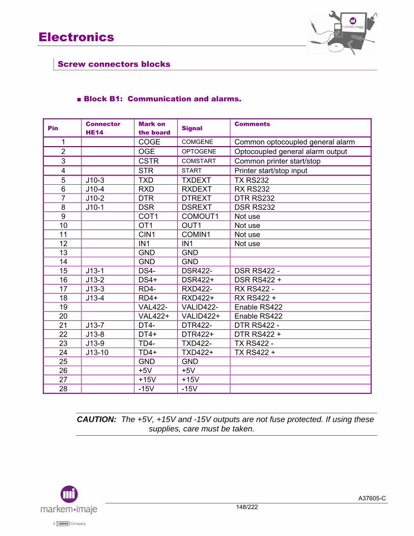
Electronics
A37605-C148/222
Screw connectors blocks
■ Block B1: Communication and alarms.
Pin Connector HE14
Mark on the board
Signal Comments
1 COGE COMGENE Common optocoupled general alarm 2 OGE OPTOGENE Optocoupled general alarm output 3 CSTR COMSTART Common printer start/stop 4 STR START Printer start/stop input 5 J10-3 TXD TXDEXT TX RS232 6 J10-4 RXD RXDEXT RX RS232 7 J10-2 DTR DTREXT DTR RS232 8 J10-1 DSR DSREXT DSR RS232 9 COT1 COMOUT1 Not use
10 OT1 OUT1 Not use 11 CIN1 COMIN1 Not use 12 IN1 IN1 Not use 13 GND GND 14 GND GND 15 J13-1 DS4- DSR422- DSR RS422 - 16 J13-2 DS4+ DSR422+ DSR RS422 + 17 J13-3 RD4- RXD422- RX RS422 - 18 J13-4 RD4+ RXD422+ RX RS422 + 19 VAL422- VALID422- Enable RS422 20 VAL422+ VALID422+ Enable RS422 21 J13-7 DT4- DTR422- DTR RS422 - 22 J13-8 DT4+ DTR422+ DTR RS422 + 23 J13-9 TD4- TXD422- TX RS422 - 24 J13-10 TD4+ TXD422+ TX RS422 + 25 GND GND 26 +5V +5V 27 +15V +15V 28 -15V -15V
CAUTION: The +5V, +15V and -15V outputs are not fuse protected. If using these supplies, care must be taken.

Electronics
A37605-C149/222
■ Blocks B2 and B3: Print head 1 and 2.
Pin Connector HE14
Mark on the board
Signal Comments
1 J11-10 GND GND 2 J11-11 +24V +24VT1
Available for accessories Maximum current available : 300 mA
3 J4-6 CTP1 COMDTOP1 4 J4-5 TOP1 DTOP1 Object detection cell input
5 CVAL1 COMVALIMP1 6 VAL1 VALIMP1 Printing validation input
7 J8-6 CTC1 COMTACHY1 8 J8-5 TAC1 TACHY1 Tacho coders input
9 J14-3 CRZ1 COMRAZC1 10 J14-4 RAZ1 RAZC1 Reset counter input
11 J14-5 CIC1 COMINCC1 12 J14-6 IC1 INCC1 Increment counter input
13 J14-7 CTO1 COMSTOPI1 14 J14-8 STO1 STOPI1 Stop printing input
15 J14-9 CSP1 COMSPROG1 16 J14-10 SPR1 SPROGI1 Complete printing output
17 J14-11 CFN1 COMVALFIN1 18 J14-12 FIN1 VALFINI1 Final value of the counter output
19 J14-13 COT1 COMOPTOT1 20 J14-14 OPT1 OPTOT1 Alarm head output
21 J14-15 GND GND 22 J8-2 GND GND
Available for accessories Maximum current available: 300 mA
23 J11-9 CDT1 COMDATA1 Common parallel interface inputs 24 J11-1 D0T1 D0T1 D0 parallel interface input 25 J11-2 D1T1 D1T1 D1 parallel interface input 26 J11-3 D2T1 D2T1 D2 parallel interface input 27 J11-4 D3T1 D3T1 D3 parallel interface input 28 J11-5 D4T1 D4T1 D4 parallel interface input 29 J11-6 D5T1 D5T1 D5 parallel interface input 30 J11-7 D6T1 D6T1 D6 parallel interface input 31 J11-8 D7T1 D7T1 D7 parallel interface input
32 J8-1 +24V +24VT1 Available for accessories Maximum current available: 300 mA

Electronics
A37605-C150/222
■ Block B4: Alarms.
Pin Mark on the board
Signal Comments
1 T1- T1- Head 1 alarm, dry contact inverted (1A) 2 T1+ T1+ Head 1 alarm, dry contact normal (1A) 3 CT1 COMT1 Head 1 alarm, dry contact common 4 T2- T2- Head 2 alarm, dry contact inverted (1A) 5 T2+ T2+ Head 2 alarm, dry contact normal (1A) 6 CT2 COMT2 Head 2 alarm, dry contact common 7 GE- GENE- General alarm, dry contact inverted (1A) 8 GE+ GENE+ General alarm, dry contact normal (1A) 9 CGE COMGENE General alarm, dry contact common
REMINDER: Optocoupled alarm outputs are also available on screw connector block B1, pins 1-2-3-4.

Electronics
A37605-C151/222
Cables between the Industrial Interface board and the IP65 external connectors
Tacho - 2 1 24V
4 Tacho + GND 3 +24V
Com Tachy
Tachy
2 4 6
1 3 5
2 4 6
1 3 5
Top - 2 1 24V
4 Top + GND 3 +24V
Com Top
Top
2 4 6
1 3 5
2 4 6
1 3 5
Red 2 1 Green
4 Orange 24V 3 Vert
Rouge
Orange
2 4 6
1 3 5
2 4 6
1 3 5
+24 V
Industrial Interface Board IP65 External connectors
J8 TACHY 1 – J6 TACHY 2
J4 CELLULE 1 - J9 CELLULE 2
J5 ALARME
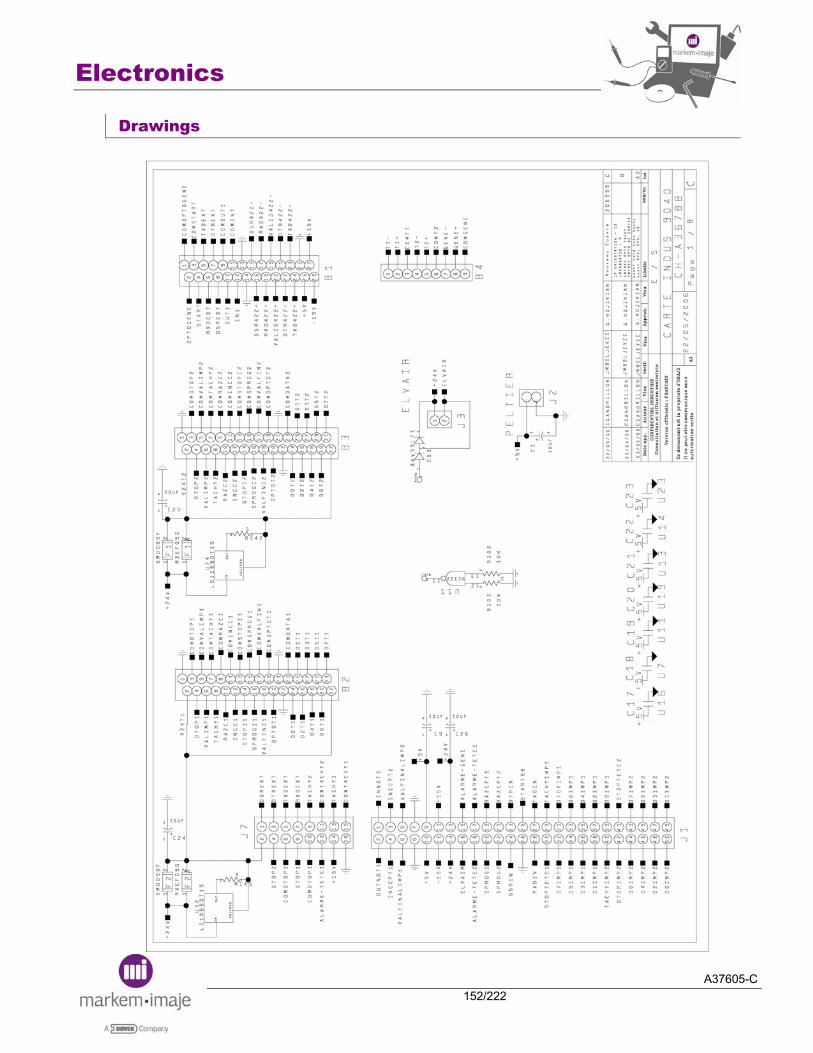
Electronics
A37605-C152/222
Drawings
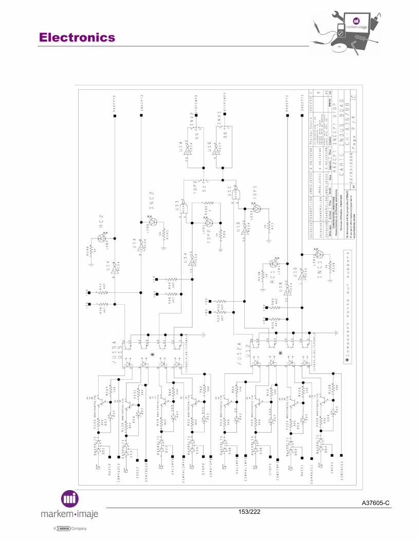
Electronics
A37605-C153/222
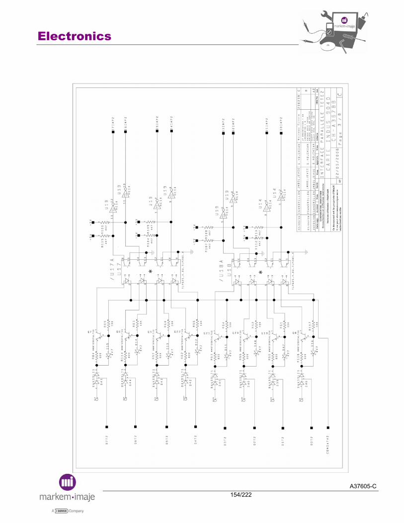
Electronics
A37605-C154/222
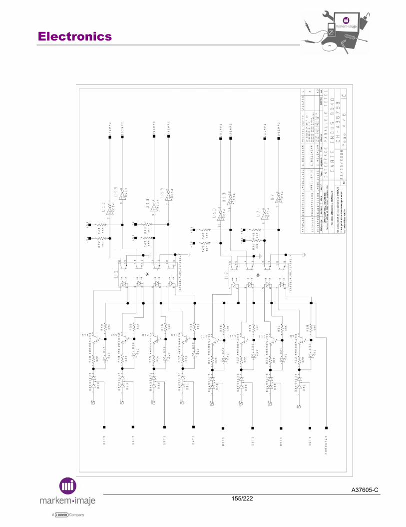
Electronics
A37605-C155/222
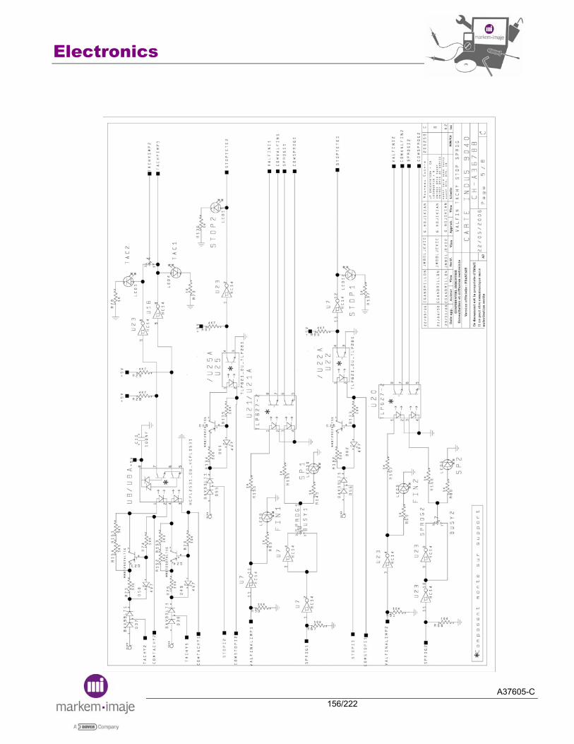
Electronics
A37605-C156/222
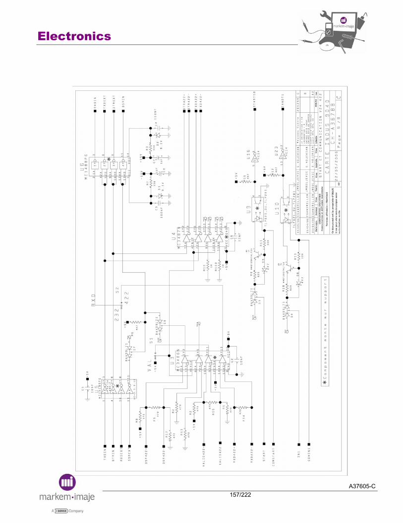
Electronics
A37605-C157/222

Electronics
A37605-C158/222

Electronics
A37605-C159/222
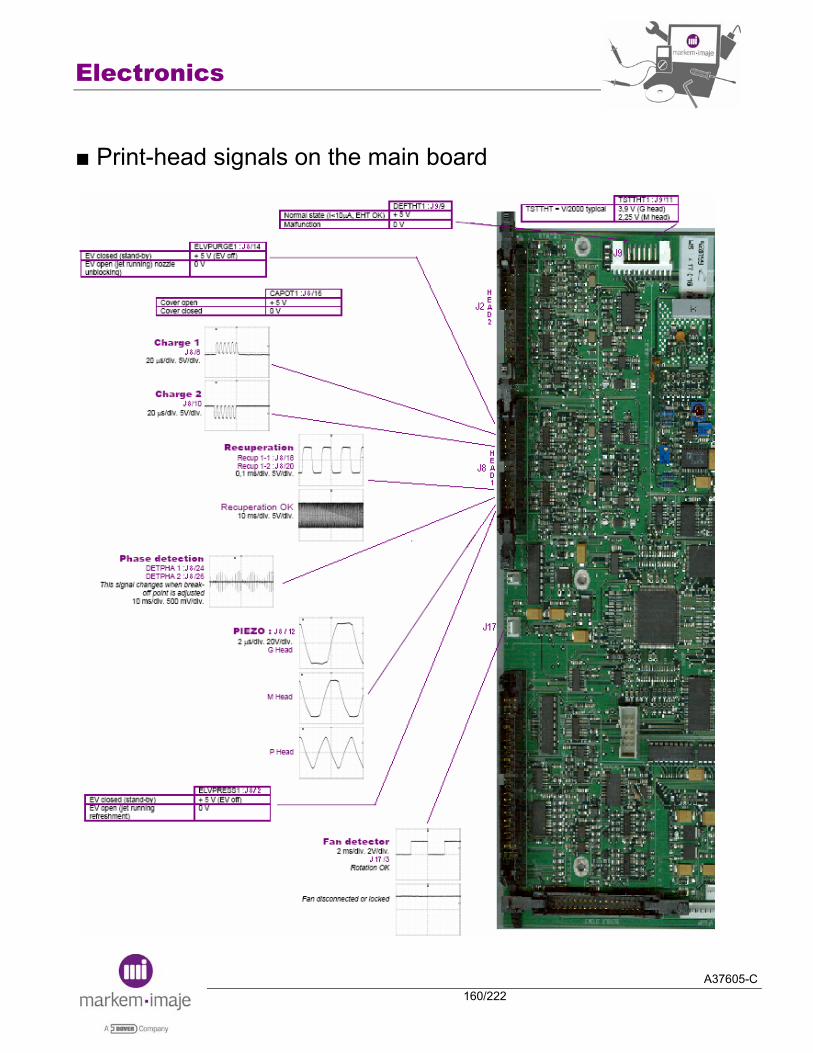
Electronics
A37605-C160/222
■ Print-head signals on the main board

Electronics
A37605-C161/222
Notes:

Electronics
A37605-C162/222
Notes:

A37605-C163/222
Hydraulics

Hydraulics
A37605-C164/222
Notes:

Hydraulics
A37605-C165/222
■ Ink/Jet speed information In order to be in conformity with the theoretical resolution in G head (2,8 dots per millimetre with typical head/object distance), we had to change the jet speed for different inks. The general rule is the following:
For G head, all base MEK inks which had a jet speed of 20m/s on Imaje S8 printers, have now a jet speed of 19.5m/s on Markem-Imaje 9040 printers. For M and P heads, no change. For water and alcohol base inks, no change. All the inks which had a jet speed different of 20m/s on S8 printers, no change.
The software of Markem-Imaje 9040 includes this new value as a standard. The IRS (Ink Running Specification) will be updated.

Hydraulics
A37605-C166/222
■ Ink/Jet speed tables
Parameters S8 Parameters 9040
Jet speed
(m/s) Jet speed
(m/s)
Viscosity management
G M P
Viscosity management
G M P 5106E-4 ORANGE FLUO 36-29s 20 20 / MEK Curve 19,5 20 /
5107-4 BLACK 36-29s 20 20 / MEK Curve 19,5 20 / 5117-4 BLUE 36-29s 20 20 / MEK Curve 19,5 20 /
5122-4 CARMIN 36-29s 20 20 24 MEK Curve 19,5 20 24
5125-4 GREEN 36-29s 20 20 / MEK Curve 19,5 20 / 5127-4 INVISIBLE FLUO 36-29s 20 / / MEK Curve 19,5 / /
5128-4 RUBINE 36-29s 20 20 24 MEK Curve 19,5 20 24
5132-4 YELLOW 36-29s 20 20 / MEK Curve 19,5 20 / 5135E-4 BLACK 36-29s 20 20 24 MEK Curve 19,5 20 24
5139-4 BLACK 36-29s 20 20 / MEK Curve 19,5 20 /
5140-4 BLACK 36-29s 20 20 24 MEK Curve 19,5 20 24 5144M-4 BLACK 36-29s 20 20 24 MEK Curve 19,5 20 24
5151-4 YELLOW 36-29s 20 20 / MEK Curve 19,5 20 /
5153-4 BROWN 36-29s 19 19 / MEK Curve 19 19 / 5157E-4 BLACK 36-29s 20 20 24 MEK Curve 19,5 20 24
5178-4 BLACK 36-29s 20 20 / MEK Curve 19,5 20 /
5189-4 GREY 36-29s 20 20 / MEK Curve 19,5 20 /
5197-4 BLACK 10°C = 55-45s 20°C = 36-29s 20 / / idem S8
5220-4 BLACK 36-29s 20 / / idem S8
5311-4 PINK specific curve / 20 / idem S8
5312-4 BLUE specific curve / 20 / idem S8
5511-4 INVISIBLE FLUO 36-29s 20 20 / idem S8
5533-4 BLACK 36-29s 19,5 / / idem S8
5535-4 INVISIBLE 34-24s 20 / / idem S8
5550-4 BLACK specific curve 20 20 / idem S8
5553-4 INVISIBLE FLUO 34-24s 20 / / idem S8
5554-4 BLACK 36-29s 20 20 / MEK Curve 19,5 20 /
5588-4 BLACK specific curve 19,5 / / idem S8

Hydraulics
A37605-C167/222
MEK curve
T° visco (s) T° visco (s) 0 36 25 27 1 36 26 27 2 36 27 26 3 35 28 26 4 35 29 26 5 34 30 25 6 34 31 25 7 33 32 25 8 33 33 24 9 33 34 24
10 32 35 24 11 32 36 24 12 31 37 23 13 31 38 23 14 31 39 23 15 30 40 22 16 30 41 22 17 30 42 22 18 29 43 22 19 29 44 22 20 29 45 22 21 28 46 22 22 28 47 22 23 28 48 22 24 27 49 22
Hydraulics
A37605-C168/222
■ Ink circuit operation Pumps
Each pump on the 9040 is driven by its own DC motor, each with a wider adjustment range.
Measuring viscosity, adding additive and detecting the low additive tank level
It was decided to manage the viscosity of all MEK inks based on the temperature. The other inks are managed based on temperature if needed by the machine/ink pair.
Principle
The viscometer is used to add additive. There are four steps:
Empty the viscometer. Open the additive addition electrovalve. Wait until the viscometer is filled to the top. Read the viscometer filling time.
The viscometer is filled in 9-14 seconds regardless of the level in the additive tank. This is much faster than the time needed to fill the viscometer with ink during the viscosity measurement and makes it possible to determine whether additive is in the tank. If the additive filling time is around the same as that for the viscosity (ink measurement), then the additive tank is empty.

Hydraulics
A37605-C169/222
Functional safety measures
Risk of additive being colored by the ink The solvent may be colored if the solvent electro valve is left open for too long. This is because the level of solvent is below the level of ink in the constant-level tube. To avoid this, we have set the solvent filling time to 2 seconds less than the ink filling time (used to monitor the actual ink viscosity). The absolute filling time cannot exceed 30 seconds.
Influence of temperature on the filling time Temperature has little effect on the viscosity of solvents, resulting in a stable filling time. The only effect temperature has is on the amount of additive added each time. The higher the temperature, the lower the ink viscosity and the less additive is actually added.
Ink quality control loop To ensure proper ink quality management (sufficient additive levels), the amount of additive added is now proportional to the number of nozzles on each machine (and corresponds to measured additive consumption levels). The rule is simple: 1 nozzle: 1 viscometer per addition of additive. 2 nozzles: 2 viscometers per addition of additive. And so on.
Additive priming When additive is added to a completely empty solvent tank, air bubbles form in the tank strainer. These air bubbles tend to block the flow of additive and remain trapped in the strainer. To prime the system, open the solvent electro valve and viscometer so that the solvent is drawn directly by the scavenge pump. Always follow the same procedure if there is a solvent problem: try adding solvent, prime the system, try again.
Hydraulics
A37605-C170/222
Risk of additive high level in viscometer not being detected To avoid overfilling the viscometer when additive is added several times in a row, we have separated each additive addition phase with an ink filling phase.
Possibilities for hourly additions of additive Solvent is added in the following manner: viscosity measured once, solvent added once, four no-load measurements, etc. Each time solvent is added, the viscosity must be measured five times (total time: approx. 20 seconds). Thus, for an average viscosity of 30 seconds, solvent can be added once every 170 seconds (21 times per hour) in individual amounts of approx. 3 cc (60 cc per hour).
Rinsing the cannon prior to short/prolonged periods of non-use
The machine will start up better if a maximum of ink is flushed from the cannon when the machine is stopped.
To do so, flow additive through the cannon at negative pressure by opening the head drain electro valve and the additive electro valve on the ink circuit. Use the 1.1 mm hose in the conduit (used for the spray in the S8) to carry the additive to the cannon. The additive inlet is protected by a 14 µm filter. Connect the hose to the tee piece after the head pressure electro valve. Place a check valve on the additive line to prevent a backflow of additive when the nozzle is started (pressure electro valve opened). The cannon rinsing cycle lasts for 6 minutes after the machine is stopped.
Additive is not needed in the head cannon in order to start the machine. This is because the direction of the nozzles cannot be changed and the jet would be outside the gutter.
At start-up, run a small amount of additive through the cannon to flush away any ink residue that may have migrated to the bottom of the cannon while the machine was off. Then run ink through the cannon at negative pressure by opening the drain and head pressure electro valves. Both negative pressure and zero pressure are necessary during this phase. The former is used to transfer ink from the tank to the cannon and the latter is needed because the drain and head pressure electro valves are opened. An EGGS ink circuit must be used as it is the only one with a separate motor for each pump, which is needed to drive the pressure and recuperation motors independently. The cannon is filled with ink in approx. 1 minute when the machine is started.
Hydraulics
A37605-C171/222
An electro valve has been installed on the recuperation line for improved cannon rinsing and filling (and greater control over the quantities of additive used).
To avoid problems of the electro valve drying out, it has been placed beneath the ink tank and remains ‘wet’ when the machine is stopped.
IMPORTANT: The additive used to rinse the cannon is discharged into the ink reservoir. Approx. 20 cc are used during the rinsing cycle and 2.5 cc when the machine is started. If the machine is stopped twice a day, add 45 cc of additive to the ink. As the machine uses approx. 5 cc per hour, ink thinning problems are possible. We have added a short machine stop cycle to avoid this (selected by the operator when ON/OFF pressed). This short stop cycle uses 4 cc of additive and lasts for about 90 seconds after the machine is stopped.

Hydraulics
A37605-C172/222
■ Ink circuit 1 head
1 Ink tank 11 Viscometer drain electro valve 21 Drain electro valve 2 Additive tank 12 Additive head filter 22 Recuperation gutter 3 Pressure motor/pump 13 Ink head filter 23 Streamer 4 Vacuum motor/pump 14 Auto-shutter connector 24 Calibrated leak 0.3mm 5 Ink filter with antipulse 15 Ventilator 25 Calibrated leak 0.7mm 6 Pressure/Temperature sensor 16 Condenser with fan 26 Calibrated leak 0.3mm 7 Viscometer 17 Ceramic calibrated tube 27 Air network input (option) 8 Nozzle rinsing electro valve 18 Cannon 28 Permanent filter drain 9 Gutter electro valve 19 One way valve (no return valve) 29 Outlet for head drying kit 10 Additive addition electro valve 20 Pressure electro valve 30 Head pressurization outlet
1 2
3
4
5 6
7
8
9
10
13
12
11
14
15
16
17
18
19
20
21
24
22
25 26
27
28
29 30
23

Hydraulics
A37605-C173/222
■ Ink circuit 2 heads 1 Ink tank 12 Gutter electro valve head 2 23 Ceramic calibrated tube 2 Additive tank 13 Additive addition electro valve 24 Cannons 3 Pressure motor/pump 14 Viscometer drain electro valve 25 Recuperation gutters 4 Vacuum motor/pump head 1 15 Additive head filter head 1 26 Recuperation one way valve 5 Vacuum motor/pump head 2 16 Ink head filter head 1 27 Drain one way valve 6 Ink filter with antipulse 17 Additive head filter head 2 28 Pressure electro valve 7 Pressure/Temperature sensor 18 Ink head filter head 2 29 Drain electro valve 8 Viscometer 19 Auto-shutter connector head1 30 2 calibrated leaks 0.3mm 9 Nozzle rinsing electro valve head 1 20 Auto-shutter connector head2 31 2 calibrated leaks 0.7mm 10 Gutter electro valve head 1 21 Ventilator 32 Calibrated leak 0.3mm 11 Nozzle rinsing electro valve head 2 22 Condenser with fan
1 2
3
5
4
6 7
8
9
10
12
11
13
14
15
16
17
18
19
30
20
21
22
23
24
25
26
27 28
29
24
25
26
27 28
29
30
31
32
Hydraulics
A37605-C174/222
■ Active Standby diagram
Active standby mode
An active standby mode has been added to the 9040 to increase the rate of good start-ups. If the printer is left on and not used for an extended period of time, it enters active standby mode for the first hours of non-use. Once every hour during this period the software starts the suction pump and opens and closes the head drain electro valve to draw air out of the cannon for 10 minutes. This drains away any condensate that forms inside the cannon.
Drain electro valve head 1
Nozzle rinsing electro valve head 1
Drain electro valve head 2
Nozzle rinsing electro valve head 2
Vacuum motor speed
Hydraulics
A37605-C175/222
■ Addition of additive with priming
Hydraulics
A37605-C176/222
■ Long shut-down
If the printer is stopped with a “Long shut down”:
- This long stop cycle lasts for about 6 minutes after the machine is stopped. - Approx. 20 cc of additive are used during the rinsing cycle and 2.5 cc when the machine is started. - The standby mode is operational for the first 74 hours of non-use. Once every hour during this period the software starts the suction pump and opens and closes the head drain electro valve to draw air out of the cannon for 10 minutes. This drains away any condensate that forms inside the cannon.
REMINDER: The quantity of additive needed for this operation, must be used during the running period which follows the re-starting of the printer.
FOR EXAMPLE: As the printer uses approx. 5 cc of additive per hour, a 4.5 hours running period is mandatory to use this additive.
Pressure ELV head 2
Vaccum Motor speed
Drain ELV head 2
Gutter ELV head 2
Nozzle rinsing ELV head 2
Pressure ELV head 1
Drain ELV head 1
Nozzle rinsing ELV head 1
Gutter ELV head 1
Pressure motor speed
Visco. ELV
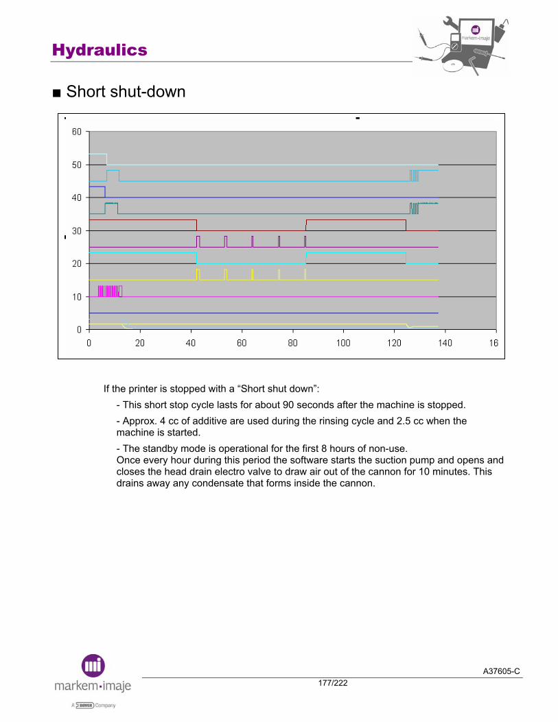
Hydraulics
A37605-C177/222
■ Short shut-down
If the printer is stopped with a “Short shut down”: - This short stop cycle lasts for about 90 seconds after the machine is stopped. - Approx. 4 cc of additive are used during the rinsing cycle and 2.5 cc when the machine is started. - The standby mode is operational for the first 8 hours of non-use. Once every hour during this period the software starts the suction pump and opens and closes the head drain electro valve to draw air out of the cannon for 10 minutes. This drains away any condensate that forms inside the cannon.

Hydraulics
A37605-C178/222
■ General Recapitulative “Stop”’ table Stop duration
9040, 9040S, 9040IP65
Stop < 2h Short Shut down
2h < Stop < 8 days Long Shut down
8 days < Stop < 15 days Flushing umbilical and head
15 days < Stop Flushing printer
Stop duration
9040 Contrast
Stop < 2h Shut down the printer with OFF key
2h < Stop < 4 days
Stop the jet Spray cleaning solution into the gutter Shut down the printer with OFF key Place anti-clogging protector under the nozzle
4 days < Stop < 1 month Flushing printer Anti-clogging protector under the nozzle
A37605-C179/222
Configuration tool
Configuration tool
A37605-C180/222
Notes:
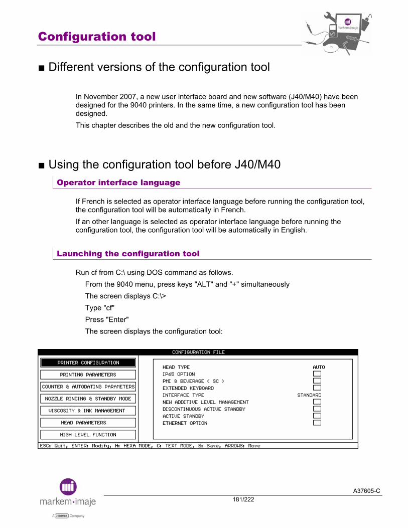
Configuration tool
A37605-C181/222
■ Different versions of the configuration tool In November 2007, a new user interface board and new software (J40/M40) have been designed for the 9040 printers. In the same time, a new configuration tool has been designed. This chapter describes the old and the new configuration tool.
■ Using the configuration tool before J40/M40 Operator interface language
If French is selected as operator interface language before running the configuration tool, the configuration tool will be automatically in French. If an other language is selected as operator interface language before running the configuration tool, the configuration tool will be automatically in English.
Launching the configuration tool
Run cf from C:\ using DOS command as follows. From the 9040 menu, press keys "ALT" and "+" simultaneously The screen displays C:\> Type "cf" Press "Enter" The screen displays the configuration tool:
Configuration tool
A37605-C182/222
Setting the options
In the configuration tool, the following command can be used: ESC: to cancel the current modification and quit the configuration tool ENTER: to modify an option H: to select hexa mode. This mode displays options as hexadecimal values (hexadecimal address and data) C: to select text mode. This mode displays options S: to save the modifications Arrows: to move from option to another
Quitting the configuration tool
Once options have been set: Press "S" to save the modifications. Press "ESC" key to quit the configuration tool and come back to DOS commands The screen displays C:\ Type "exit" Press Enter The screen displays the 9040 menu
Enabling the options
If options have been modified, restart the printer with ON/OFF key. Otherwise, the modification will not be taken into account.

Configuration tool
A37605-C183/222
■ Options description of the configuration tool before J40/M40 Printer configuration
Head type
Description: the printer recognizes the head type automatically except for 4 jet head. Choice:
AUTO for every head type configuration except 4 jet head 4 JETS mandatory for 4 jet head printer
IP65 option
Description: IP65 option setting
Choice: for non IP65 printer
for IP65 printer
PMI & beverage ( SC )
Description: be checked in case of 9040 S printer, allows to inverse message only on jet 1.
Choice for other 9040 printer
for 9040 S printer
Configuration tool
A37605-C184/222
Extended keyboard
Description: the extended keyboard option allows to use the “ALT” key when editing a message. This option is used with the Arabic keyboard
Choice no extended keyboard
extended keyboard
Interface type
Description: allows to choose the 9040 operator interface with or without icons and the way the icons are managed.
Choice STANDARD: S8 user interface. WITH ICONS: displays icons of S8 direct access keys. WITH CONTEXT ICONS: icons change according to the displayed menu.
New additive level management
Description: Not used for 9040 printer.
DISCONTINUOUS ACTIVE STANDBY
Description: Not used for 9040 printer.
Active standby
Description: enables active standby, see figure below. Prerequisite: Nozzle rinsing option must be available.
Choice: no active standby
active standby
After stop the printer, if the active standby is selected, an hydraulic action is performed during T1 every T2 second, these cycles are reproduced during T3 time.

Configuration tool
A37605-C185/222
T2
T1
T3
T1: Action time of active standby (=Active standby duration) T2: Active standby period T3: Active standby time (could be the short time or the long time)
Ethernet option
Description: Enables Ethernet link, with Ethernet board connected, the external serial link (RS232 or RS422) is disabled
Choice: Ethernet disabled
Ethernet enabled
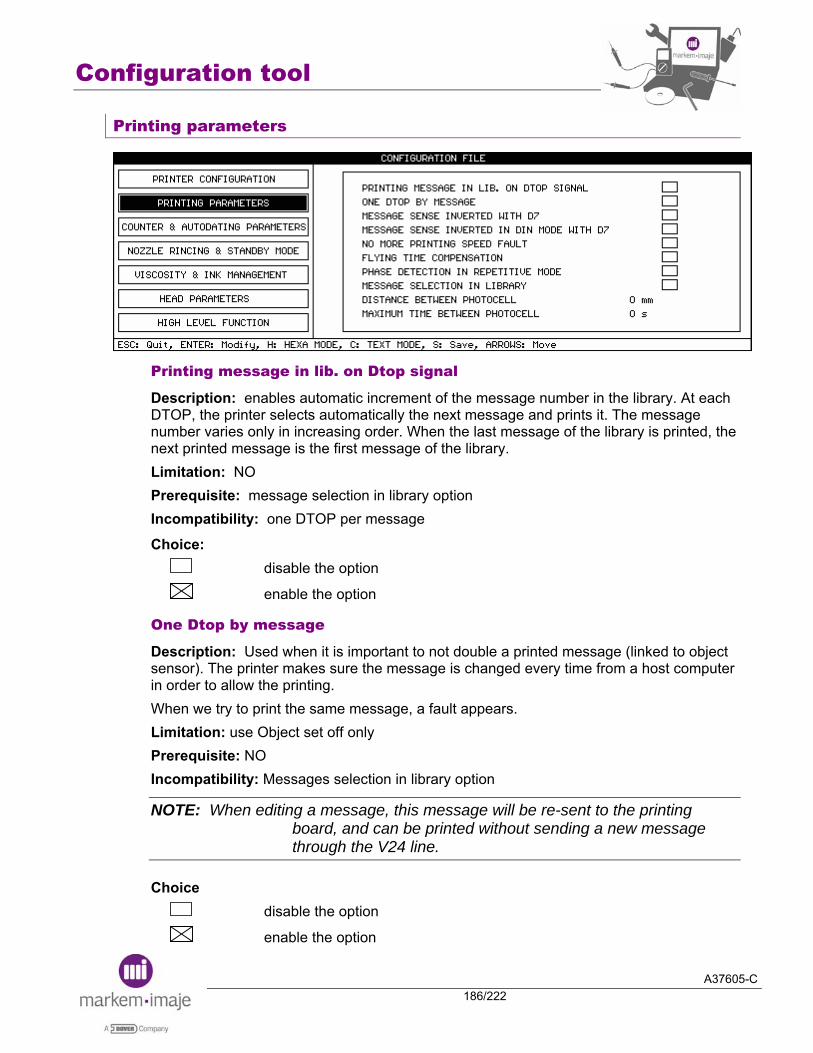
Configuration tool
A37605-C186/222
Printing parameters
Printing message in lib. on Dtop signal
Description: enables automatic increment of the message number in the library. At each DTOP, the printer selects automatically the next message and prints it. The message number varies only in increasing order. When the last message of the library is printed, the next printed message is the first message of the library. Limitation: NO Prerequisite: message selection in library option Incompatibility: one DTOP per message
Choice: disable the option
enable the option
One Dtop by message
Description: Used when it is important to not double a printed message (linked to object sensor). The printer makes sure the message is changed every time from a host computer in order to allow the printing. When we try to print the same message, a fault appears. Limitation: use Object set off only Prerequisite: NO Incompatibility: Messages selection in library option
NOTE: When editing a message, this message will be re-sent to the printing board, and can be printed without sending a new message through the V24 line.
Choice disable the option
enable the option
Configuration tool
A37605-C187/222
Message sens inverted with D7
Description: with this option, it is possible to have an input for the message sense inversion. When this option (Message sense inversion) is selected it is possible to use the bit 7 of the parallel interface as a message direction inversion input. Note: This input is an input of the parallel port, therefore the data must be validated by an external DTOP. Consequently, It is not possible to modify the sense message during a repetitive printing or during a printing with the Top repetition mode. Limitation: NO Prerequisite: complete industrial interface board Incompatibility: it is not possible to use the message selection in BCD mode because the input D7 is already used.
Choice: disable the option
enable the option
Message sens inverted in DIN Mode with D7
Description: with this option, it is possible to have an input for the message sense inversion not the normal way but the DIN mode way. When this option (Message sense inversion) is selected it is possible to use the bit 7 of the parallel interface as a DIN mode inversion of the message input. Note: This input is an input of the parallel port, therefore the data must be validated by an external DTOP. Consequently, It is not possible to modify the sense message during a repetitive printing or during a printing with the Top repetition mode. Limitation: NO Prerequisite: complete industrial interface board Incompatibility: it is not possible to use the message selection in BCD mode because the input D7 is already used.
Choice disable the option
enable the option
Configuration tool
A37605-C188/222
No more printing speed fault
Description: this option allows to ignore the printing speed fault. If the printing speed overpasses the maximum allowed by the symbol generator, the printing speed fault is not given to the user. Limitation: NO Prerequisite: NO Incompatibility: NO
Choice: disable the option
enable the option
Flying time compensation
Description: this option has been developed to minimize the printing position variation on the support when the speed varies around the printing speed set into the message parameters (problem due to the flying time of the drops from the cannon to the support).
Limitation: Object set off only and tachy mode. A margin is necessary in the message in order to reduce it if the printing speed increases. Prerequisite: NO Incompatibility: NO
Choice: disable the option
enable the option
Phase detection in repetitive mode
Description: Not used for 9040, because on 9040, the phase detection could be done during printing.

Configuration tool
A37605-C189/222
Message selection in library
Description: allows quick change of the message to be printed. A message library is necessary. Series of message numbers are sent through the parallel interface board from external system. Use with compatibility option, the selection of message is done like S8 printer. Limitation: NO Prerequisite: complete industrial interface Incompatibility: NO
Choice: disable the option
enable the option
Distance between photocells
Description: Not available on 9040 version M05 / J05. Limitation: NO Prerequisite: NO Incompatibility: NO Choice: From 0 to 999 mm
Maximum time between photocells
Description: Not available on 9040 version M05 / J05. Limitation: NO Prerequisite: NO Incompatibility: NO Choice: From 0 to 255 s
Configuration tool
A37605-C190/222
Counter & autodating parameters
Counter increasing with fault on the head
Description: this function enables the counter to be updated with the cell tops even if the print heads are not ready to print. That means that just after printer start-up, the counter will be incremented, even if a head is faulty. Limitation: object set off only Prerequisite: NO Incompatibility: NO
Choice disable the option
enable the option
No counter reset
Description: normally, changing the counter parameters resets the counter to the initial value. This option allows to change the counter parameters without reset of the counter to the initial value. Limitation: NO Prerequisite: NO Incompatibility: NO
Choice: disable the option
enable the option
Configuration tool
A37605-C191/222
Julian postdate with offset
Description: used when you want to have an offset on the post-date and a particular printing.
Example:
Real post-date
Julian post-date
Offset (days) Printing with option
Printing without option (402-365)
02/Jan/07 002 400 402 37
Limitation: Julian date + offset ≤ 999 ; offset max. ≤ 633 Prerequisite: NO Incompatibility: NO
Choice: disable the option
enable the option
First day of the week
Description: with this option, it is possible to choose the first day of the week. The week number change is synchronised with the first day of the week. Limitation: NO Prerequisite: NO Incompatibility: NO Choice: MONDAY, TUESDAY, WEDNESDAY, THURSDAY, FRIDAY, SATURDAY, SUNDAY
Postdate change on the first day of the week
Description: this option allows the printer to synchronize the postdate change with the first day of the week. Limitation: NO Prerequisite: NO Incompatibility: NO
Choice: disable the option
enable the option

Configuration tool
A37605-C192/222
ACK with simplified protocol
Description: this option allows the printer to answer ACK when using a simple protocol in standard mode. Limitation: NO Prerequisite: Simplified protocol Incompatibility: NO
Choice: disable the option
enable the option
Compatibility with S4/S8
Description: this option allows: the management of the parallel interface like S8 the reverted printing with the same way as a S8.
Limitation: in case of reverted printing, jets are reverted as S8 but lines within a jet are not reverted.
Example: User
interface S8
reverted printing
9040 reverted printing (enabled option)
9040 reverted printing (disabled option)
Mono-jet
line 1 line 2 line 3
line 3 line 2 line 1
line 1 line 2 line 3
Bi-jet line 1 line 2 line 3
line 4 line 5 line 6
line 6 line 5 line 4
line 3 line 2 line 1
line 4 line 5 line 6
line 1 line 2 line 3
line 1 line 2 line 3
line 4 line 5 line 6
Prerequisite: NO Incompatibility: NO
Choice: disable the option
enable the option

Configuration tool
A37605-C193/222
Code 39 checksum modulus 10
Description: this new option allows to change the code39 checksum from modulus 43 (standard) to modulus 10. Limitation: NO Prerequisite: NO Incompatibility: NO
Choice: disable the option (code 39 modulus 43)
enable the option (code 39 modulus 10)
No quiet zone with datamatrix
Description: this new option allows to suppress the quiet zone of a Datamatrix (=margin define in the standard of the Datamatrix). Limitation: NO Prerequisite: NO Incompatibility: NO
Choice: disable the option (standard Datamatrix quiet zone)
enable the option (no Datamatrix quiet zone)
Counter 1 & 2 reset by hardware input
Description: this new option allows to reset counters 1 and 2 by the counter reset input (=RAZC1 input for head 1 and RAZC2 input for head 2). Limitation: NO Prerequisite: NO Incompatibility: NO
Choice: disable the option
enable the option
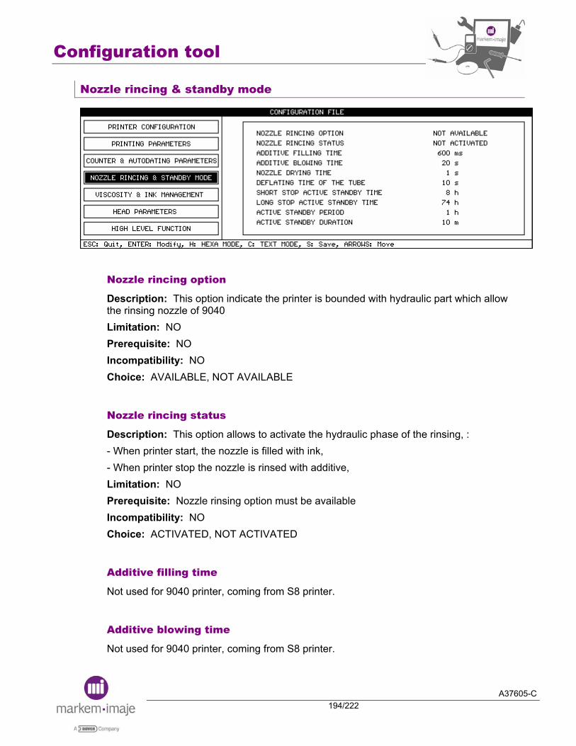
Configuration tool
A37605-C194/222
Nozzle rincing & standby mode
Nozzle rincing option
Description: This option indicate the printer is bounded with hydraulic part which allow the rinsing nozzle of 9040 Limitation: NO Prerequisite: NO Incompatibility: NO Choice: AVAILABLE, NOT AVAILABLE
Nozzle rincing status
Description: This option allows to activate the hydraulic phase of the rinsing, : - When printer start, the nozzle is filled with ink, - When printer stop the nozzle is rinsed with additive, Limitation: NO Prerequisite: Nozzle rinsing option must be available Incompatibility: NO Choice: ACTIVATED, NOT ACTIVATED
Additive filling time
Not used for 9040 printer, coming from S8 printer.
Additive blowing time
Not used for 9040 printer, coming from S8 printer.

Configuration tool
A37605-C195/222
Nozzle drying time
Not used for 9040 printer, coming from S8 printer.
Deflating time of the tube
Not used for 9040 printer, coming from S8 printer.
Short stop active standby time
Description: see chapter 2.1.8, this is the time of the active standby when the operator have choose the short stop of the printer. Limitation: NO Prerequisite: NO Incompatibility: NO Choice: From 0 to 99 hours
NOTE: the default value should not be modified
Long stop active standby time
Description: see chapter 2.1.8, , this is the time of the active standby when the operator have choose the long stop of the printer. Limitation: NO Prerequisite: NO Incompatibility: NO Choice : From 0 to 99 hours
NOTE: the default value should not be modified
Active standby period
Description: see chapter 2.1.8, during the active standby we have many cycles reproduced each period. Limitation: NO Prerequisite: NO Incompatibility: NO Choice: From 0 to 99 hours.
NOTE: the default value should not be modified
Configuration tool
A37605-C196/222
Active standby duration
Description: see chapter 2.1.8, during the active standby we have many cycles reproduced, for each cycles we have time defined for execute hydraulic action. Limitation: NO Prerequisite: NO Incompatibility: NO Choice: From 0 to 255 minutes
NOTE: the default value should not be modified

Configuration tool
A37605-C197/222
Viscosity & ink management
Management of the viscosity in temperature
Description: this option allows to manage the viscosity with the temperature. Limitation: NO Prerequisite: NO Incompatibility: NO
Choice: disable the option (in that case standard viscosity curves appear on the screen
instead of the 50 viscosity values)
enable the option (in that case 50 viscosity values appear as shown above)
Ink with inverted viscosity
Description: this option is used in case of inverted viscosity curve (the viscosity increases with additive addition) Limitation: NO Prerequisite: inverted viscosity ink Incompatibility: NO
Choice: disable the option
enable the option
Configuration tool
A37605-C198/222
Ajout elementaire de solvant
Depending of ink.
Viscosity curve (in seconds)
Description: viscosity values Limitation: NO Prerequisite: NO Incompatibility: No
Choice: STANDARD INK AND PIGMENTED (with management of the viscosity in temperature disabled): from printer start-up, the viscosity reference changes every 20 minutes to the final viscosity reference according to a table that contains 10 values (from 0 to 89 s). One table among 8 can be selected and every value of the table can be modified. With management of the viscosity in temperature enabled: the viscosity reference changes according to a table (from 0°C to 49°C) that contains 50 values.
Jet speed
Description: value of the jet speed according to ink. Limitation: NO Prerequisite: NO Incompatibility: NO Choice: from 0 to 25.5 m/s (step: 0.1 m/s)
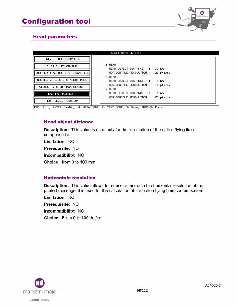
Configuration tool
A37605-C199/222
Head parameters
Head object distance
Description: This value is used only for the calculation of the option flying time compensation. Limitation: NO Prerequisite: NO Incompatibility: NO Choice: from 0 to 100 mm
Horizontale resolution
Description: This value allows to reduce or increase the horizontal resolution of the printed message, it is used for the calculation of the option flying time compensation. Limitation: NO Prerequisite: NO Incompatibility: NO Choice: From 0 to 100 dot/cm
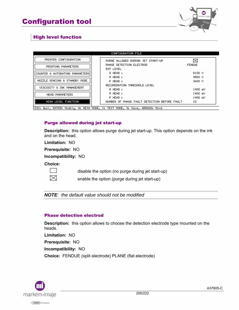
Configuration tool
A37605-C200/222
High level function
Purge allowed during jet start-up
Description: this option allows purge during jet start-up. This option depends on the ink and on the head. Limitation: NO Prerequisite: NO Incompatibility: NO
Choice: disable the option (no purge during jet start-up)
enable the option (purge during jet start-up)
NOTE: the default value should not be modified
Phase detection electrod
Description: this option allows to choose the detection electrode type mounted on the heads. Limitation: NO Prerequisite: NO Incompatibility: NO Choice: FENDUE (split electrode) PLANE (flat electrode)
Configuration tool
A37605-C201/222
EHT level:
From 3600 V to 8100 V (step: 300 V)
NOTE: the default value should not be modified
Number of phase fault detection before fault:
From 0 to 99
NOTE: the default value should not be modified

Configuration tool
A37605-C202/222
■ Using the configuration tool since J40/M40
To access the configuration tool from the 9040 menu, press keys and simultaneously. The following screen will appear:
If French is selected as operator interface language before running the configuration tool, the configuration tool will appear in French. If any other language is selected as operator interface language before running the configuration tool, the configuration tool will be displayed in English.
To enter a menu, select it using the keys and on the keyboard and press .
NOTE: press to get help on navigation in the Toolbox
Configuration tool
A37605-C203/222
■ Options configuration
Select Options Configuration and press Enter to access the configuration tabs. Among the many tabs shown in this view, several printer settings and options can be configured.
Press keys and then simultaneously to navigate from one tab to the next.

Configuration tool
A37605-C204/222
The Printer Configuration Tab
Head type
4 jets: for 4 jet Printers AUTO: for all other configuration
Interface type
STANDARD: S8 user interface FIXED ICONS: displays icons of S8 direct access keys CONTEXTUAL ICONS: icons change according to the menu displayed
Vacuum motor speed (not available on J40, available since J41)
By fault, the value is 1500. Can be adjust between 1500 and 3500
Distance between photocells:
Not Available
Maximum time between photocells:
Not Available

Configuration tool
A37605-C205/222
IP65:
For IP65 printers
Wide keyboard:
Allows using the “ALT” key when editing a message with the Arabic keyboard
Ack with simplified protocol:
Allows the printer to answer ACK when using a simple protocol in standard mode.
Compatibility with S4/S8:
The management of the parallel interface and reverted printing are the same as S8 printers. Limitation: in case of reverted printing, jets are reverted as in the S8 but the lines in a jet are not reverted.
Code 39: checksum modulo 10:
Allows changing the calculation of the code 39 checksum from 43 (standard) to 10.
No quiet zone with datamatrix:
Option to reduce the code’s margin, as defined in the Datamatrix specifications.
One DTOP by message:
The printer makes sure the message is modified from a host computer before allowing the printing. Otherwise, a fault appears. Limitation: Object set off only Incompatibility: option Message selection in library
Update message out of printing:
This option can be used in repetitive mode. The next message to be printed can be sent to the printer using the V24 link during the current printing.

Configuration tool
A37605-C206/222
The Printing Parameters Tab
Extended Graphic mode:
Allows using a font which contains up to 256 symbols. (Standard fonts contains up to 224 symbols)
PMI and Beverage (9040S):
Select this option for 9040S printers to reverse the message on jet 1 only.
Printing message library on DTOP signal:
Enables automatic increment of the message number in the library. At each DTOP, the printer automatically selects and prints the next message. The message number varies only in increasing order. When the last message of the library is printed, first message of the library is printed next. Prerequisite: option Message selection in library. Incompatibility: one DTOP by message.
Message orientation inverted with D7:
Allows having an input for the message sense inversion. When this option is selected it is possible to use the bit 7 of the parallel interface as a message direction inversion input.
NOTE: this input is an input of the parallel port, therefore the data must be validated by an external DTOP. Consequently, It is not possible to modify the sense message during a repetitive printing or during a printing with the Top repetition mode.
Prerequisite: complete industrial interface board Incompatibility: it is not possible to use the message selection in BCD mode because the input D7 is already used.
Configuration tool
A37605-C207/222
Message orientation inverted in DIN mode with D7:
Allows having an input for the message orientation: not the normal way but the DIN mode way. When this option is selected, it is possible to use the bit 7 of the parallel interface as a DIN mode inversion of the message input.
NOTE: this input is an input from the parallel port, therefore the data must be validated by an external DTOP. Consequently, it is not possible to modify the message’s orientation during a repetitive printing or during a printing with the Top repetition mode.
Prerequisite: complete industrial interface board Incompatibility: it is not possible to use the message selection in BCD mode because the input D7 is already used.
No more printing speed fault:
Allows ignoring the printing speed fault. If the printing speed overpasses the maximum allowed by the symbol generator, the printing speed fault is not given to the user.
Metric interval:
In repetitive mode, the Interval in the message parameters gives the distance between the end of the previous printing and the beginning of the next one. With the option Metric interval, the Interval in the message parameters gives the distance between the beginning of the previous printing and the beginning of the next one. This option limits interval variation between printed messages in repetitive mode. Limitation: no barcode in the message. 10 ms are required between two printings.
Flying time compensation:
Allows minimising the printing position variation on the support when the speed varies from the printing speed set into the message parameters (problem is due to the flying time of the drops from the cannon to the support). Limitation: Object set off only and tachy mode. A margin is necessary in the message in order to reduce it if the printing speed increases.
Message selection in library:
Allows quick change of the message to be printed. Series of message numbers are sent through the parallel interface board from external system. Used with compatibility option, the selection of message is done like S8 printer. Prerequisite: complete industrial interface

Configuration tool
A37605-C208/222
Meter/feet conversion:
An external variable can contain the corresponding value in feet or meters of counter 1. Feet to meters conversion external variable = counter 1 x 0.3046 Meters to feet conversion external variable = counter 1 x 3.2808 When using this option, the conversion must be set into the Printer preparation / Initialization / Feet/Meter conversion menu:
Jets sense inverted:
With 2 jet printers, printing on jet 1 and jet 2 are rotated by 180 degrees.
Limitation: length of every line must be exactly the same. Add tabulation if need. Otherwise, option Manage message’s data by jet must be also used.
2 lines 7 dots with 12m head – small gap:
This option can be selected when using algorithm 007 and 060 in message parameters in order to move up the printing of the jet 2 (10 drops above the initial location).
Manage message’s data by jet:
When using option Jets sense inverted, if the length of each line is not exactly the same, the option must also be used.
Message displayed in Message editing menu
Message printed
Jet 1
Jet 2

Configuration tool
A37605-C209/222
The Counter / Autodating Param. Tab
First day of the week:
The week number change is synchronised with the first day of the week (from Monday to Sunday).
Postdate change on the first day of the week:
Allows the printer to synchronize the postdate change with the first day of the week.
Postdate locked at message selection:
Allows to give the postdate a fixed value once the message has been selected.
Input POSDATE 1 value and update Library in Production menu (not available on J40, available since J41)
Allows giving the duration of the POSDATE 1 from the active message and up-dating all the messages in the library witch have the same Unit (day or month)
Counter increasing with fault on the head:
Enables the counter to be updated with the cell tops even if the print heads are not ready to print. That means that just after printer start-up, the counter will be incremented, even if a head is faulty. Limitation: object set off only
No counter reset:
Normally, changing the counter parameters resets the counter to its initial value. This option allows changing the counter parameters without reset of the counter to the initial value.
Counter 1 and 2 reseted by hardware input:
Allows resetting counters 1 and 2 by the counter reset input (=RAZC1 input for head 1 and RAZC2 input for head 2).
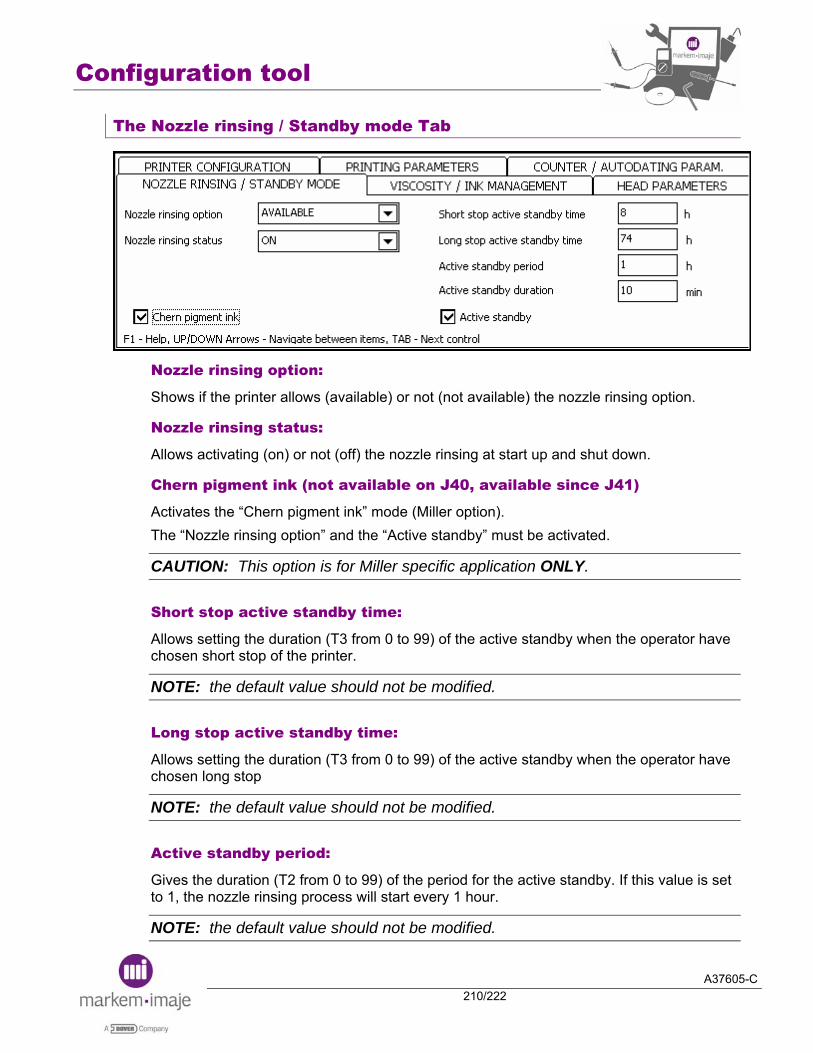
Configuration tool
A37605-C210/222
The Nozzle rinsing / Standby mode Tab
Nozzle rinsing option:
Shows if the printer allows (available) or not (not available) the nozzle rinsing option.
Nozzle rinsing status:
Allows activating (on) or not (off) the nozzle rinsing at start up and shut down.
Chern pigment ink (not available on J40, available since J41)
Activates the “Chern pigment ink” mode (Miller option). The “Nozzle rinsing option” and the “Active standby” must be activated.
CAUTION: This option is for Miller specific application ONLY.
Short stop active standby time:
Allows setting the duration (T3 from 0 to 99) of the active standby when the operator have chosen short stop of the printer.
NOTE: the default value should not be modified.
Long stop active standby time:
Allows setting the duration (T3 from 0 to 99) of the active standby when the operator have chosen long stop
NOTE: the default value should not be modified.
Active standby period:
Gives the duration (T2 from 0 to 99) of the period for the active standby. If this value is set to 1, the nozzle rinsing process will start every 1 hour.
NOTE: the default value should not be modified.
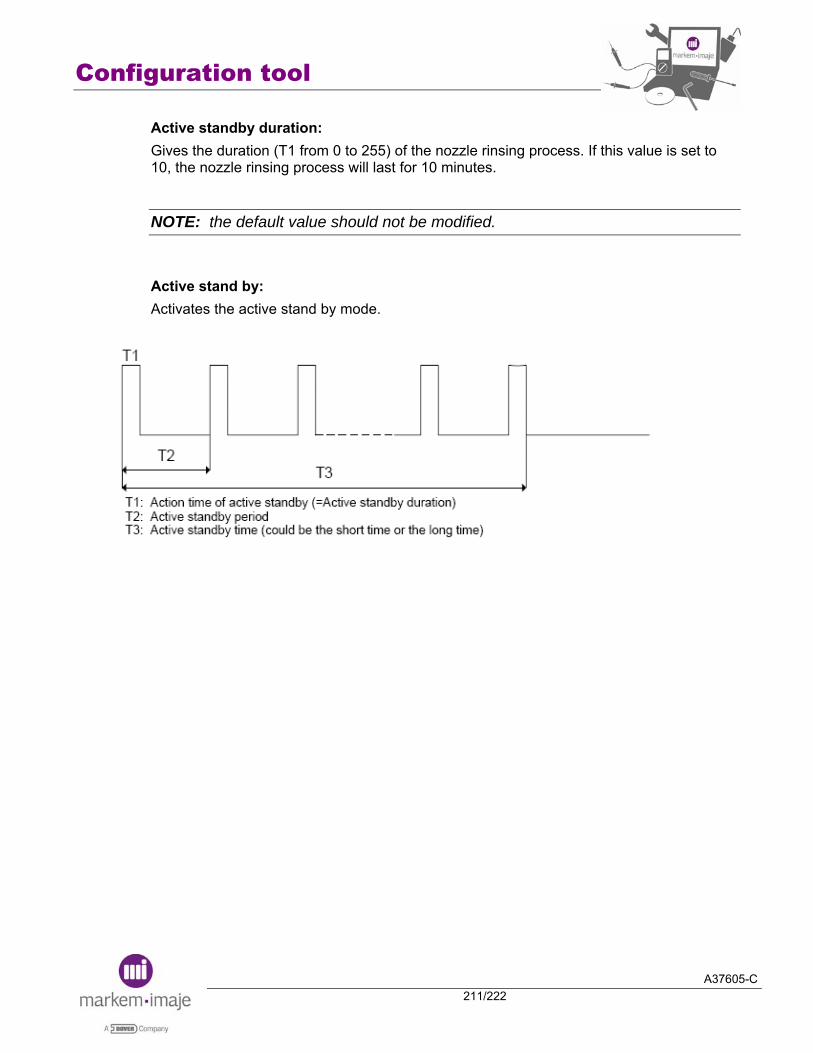
Configuration tool
A37605-C211/222
Active standby duration: Gives the duration (T1 from 0 to 255) of the nozzle rinsing process. If this value is set to 10, the nozzle rinsing process will last for 10 minutes.
NOTE: the default value should not be modified.
Active stand by: Activates the active stand by mode.
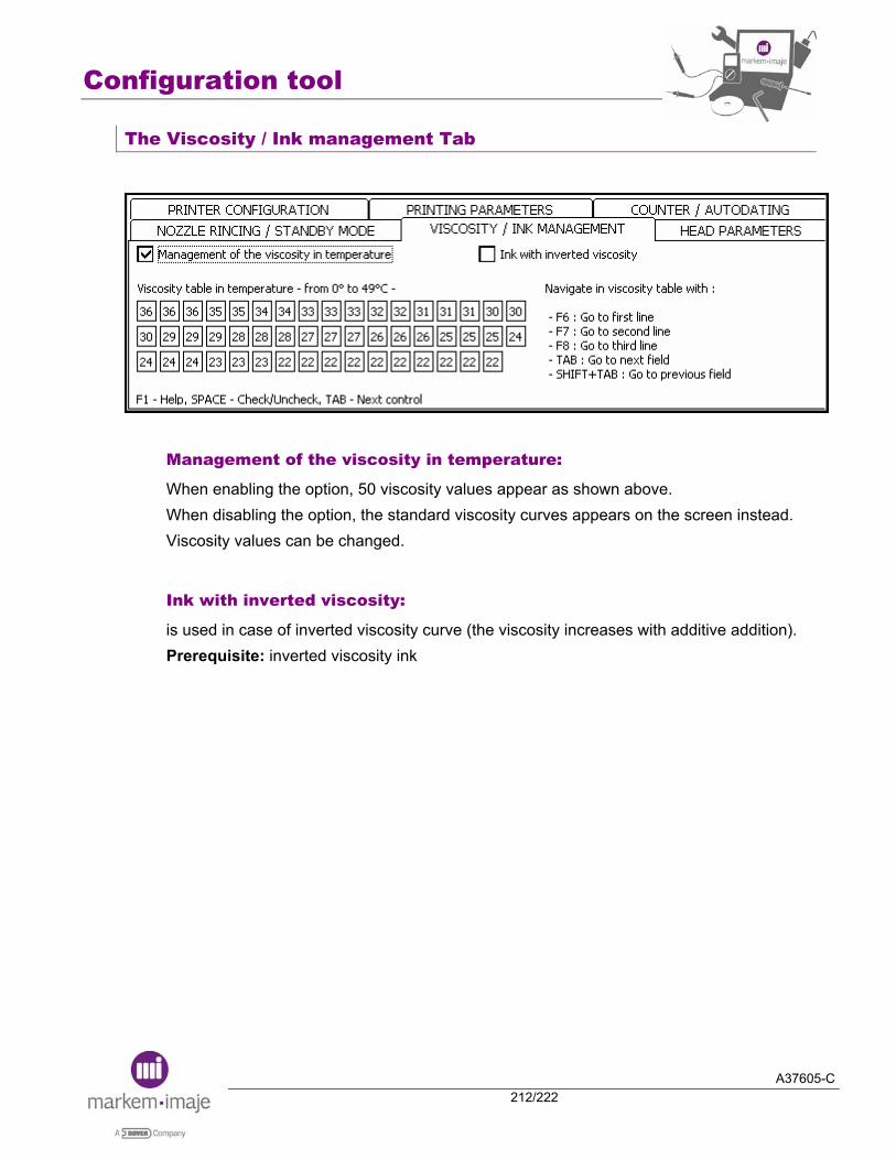
Configuration tool
A37605-C212/222
The Viscosity / Ink management Tab
Management of the viscosity in temperature:
When enabling the option, 50 viscosity values appear as shown above. When disabling the option, the standard viscosity curves appears on the screen instead. Viscosity values can be changed.
Ink with inverted viscosity:
is used in case of inverted viscosity curve (the viscosity increases with additive addition). Prerequisite: inverted viscosity ink

Configuration tool
A37605-C213/222
Tab Head parameters
Choice of the head to configure:
G; M or P head according to the printer configuration.
Head-object distance:
is used for the calculation of the flying time. Value from 0 to 100 mm.
Horizontal resolution:
Reduces or increases the horizontal resolution (from 0 to 100 dot/mm) of the printed message. It is used for the calculation of the flying time.
EHT level:
From 3600 V to 8100 V (step = 300 V)
NOTE: the default value should not be modified.
Jet speed: standard ink:
Gives the jet speed for non pigmented ink from 0 to 25.5 m/s.
Jet speed: pigmented ink:
Gives the jet speed for pigmented ink from 0 to 25.5 m/s.

Configuration tool
A37605-C214/222
Recuperation threshold:
Is a recuperation level to manage the recuperation fault.
NOTE: the default value should not be modified.
Phase detection electrode:
Must be set according to the print head (plane or split)
Number of phase fault detection before fault:
From 0 to 99
NOTE: the default value should not be modified
Purge allowed during jet start-up:
Allows purge during jet start-up. This option depends on the ink and on the head.
NOTE: the default value should not be modified.
FT163 ink management:
Must be selected if the printer runs with ink FT163.
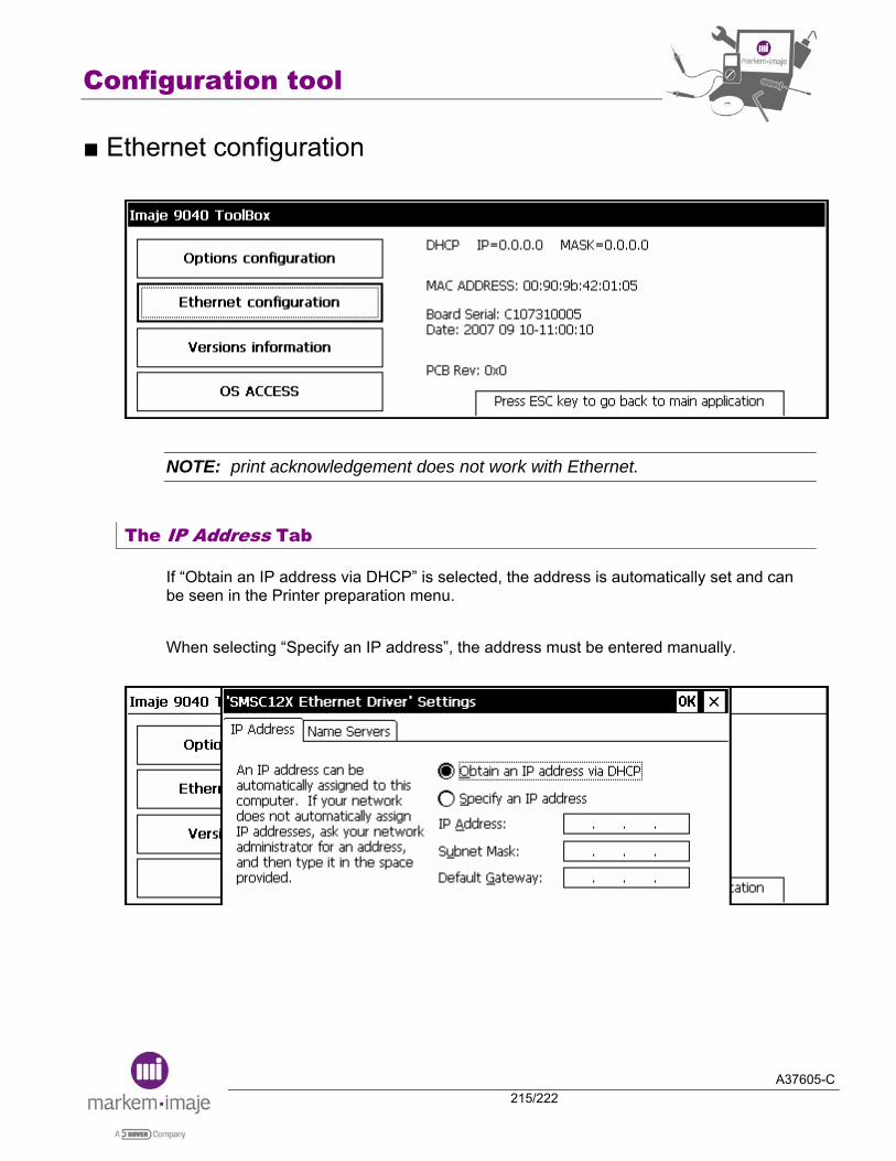
Configuration tool
A37605-C215/222
■ Ethernet configuration
NOTE: print acknowledgement does not work with Ethernet.
The IP Address Tab
If “Obtain an IP address via DHCP” is selected, the address is automatically set and can be seen in the Printer preparation menu. When selecting “Specify an IP address”, the address must be entered manually.

Configuration tool
A37605-C216/222
Tab Name Servers
This tab is unused. It has been created for future application.

Configuration tool
A37605-C217/222
■ Versions information
This screen gives information about the revision of the Operating System.
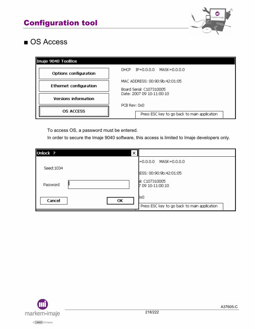
Configuration tool
A37605-C218/222
■ OS Access
To access OS, a password must be entered. In order to secure the Imaje 9040 software, this access is limited to Imaje developers only.
Configuration tool
A37605-C219/222
Notes:

Configuration tool
A37605-C220/222
Notes:


Head Office 9, rue Gaspard Monge BP 110 26501 Bourg-lès-Valence Cedex France Tel : (33) 4 75 75 55 00 Fax : (33) 4 75 82 98 10 http://www.markem-imaje.com
A37605-C
July 2008