pressure relief valvesvalves
TRANSCRIPT
304C
Series 2600Pressure Relief ValvesVallves
8
General Technical Information
Standard Flanged Connections
1. All steel raised face flanges are supplied with a serrated spiral finish with 45 to 55 grooves per inch and a finish between 125 and 160 AARH.
2. All ring joint flanged facings are supplied for octagonal or oval gaskets.
3. Facings other than raised face or large male can be supplied at additional cost.
4. Flange ratings that conform to ANSI B16.5 are indicated on each Orifice Selection Table. Heavier outlet flanges can be supplied at additional cost. For flange dimensions, see ANSI Dimension Table, page 77.
5. Drilling of all flanges always straddles the valve center line.
Valve Trim
Trim is a term that generally refers to internal parts of a pressure relief valve. Unless noted, valve trim in a Farris pressure relief valve specifically includes the nozzle and disc only. Standard bills of materials for all 2600 Series valves are located on pages 12 and 13. For low temperature and corrosive service materials, see pages 17 through 21. If other than standard trim or metallurgy is required, this must be specified.
Differential Between Operating and Set Pressure
For best performance in process applications, we recommend pressure relief valves be set to open at a minimum of 10% or 25 psig above the operating pressure. A suitable margin above the operating pressure should be provided in order to prevent any unintended operation of the pressure relief valve. Refer to ASME Section VIII Pressure Vessel Code, Appendix M, Paragraph M-10, Pressure Differentials for Pressure Relief Valves as well as to Farris Technical Recommendations for complete information.
In the case of pump and compressor discharge lines, a greater differential is recommended if possible, since pulsations within the system can result in faulty valve operation. Consequently, the pressure relief valve should be set as high above the discharge line pressure as possible.
Set Pressure Compensation for Temperature
An increase in temperature causes a reduction of valve set pressure as a result of the direct effect of temperature on the spring and expansion of body and bonnet which reduces spring loading. Since pressure relief valves are invariably tested at atmospheric temperature, it is customary to adjust the set pressure at ambient conditions to compensate for higher operating temperatures as indicated in the following table.
All Service Fluids
Steam service valves are tested on steam by the manufacturer and require no additional temperature compensation. Where the set pressure is above the production steam test facility limits, Section VIII steam valves may be tested on air. When steam valves are tested on air, compensation shown in the All Service Fluids Table should be used.
Low Pressure Settings
Low set pressure limits are indicated in the following table. These limits apply to both metal-to-metal and O-ring seat construction. Low pressure settings may be governed by valve design and performance and/or Code application limits. Pressure vessels having operating pressures not exceeding 15 psig are not considered within the scope of the ASME Code, Section VIII. Accordingly, pressure relief valve requirements for such applications are governed by other Codes and Standards that should be consulted.
The sizing equations for compressible fluids provided herein are valid for sonic flow conditions and should not be used to size pressure relief valves for applications in which subsonic (below 15 psig) flow conditions may exist. Low pressure applications can be reviewed by the Factory and special valves provided to meet those requirements.
*Low set pressure limit for “D” and “E” orifice BalanSeal (balanced bellows)
valves are 50 psig and 25 psig respectively.
Operating Temperature % Increase in Set Pressure At Atmospheric Temperature
-450° F to 300° F None301° F to 600° F 1%601° F to 900° F 2%901° F to 1200° F 3%
Valve Series ConstructionLow Set
Pressure Limit (psig)
2600 2600S 2600L
Conventional 15
2600 2600S 2600L
2600 Bal/Piston
BalanSeal BalanSeal/
Piston15*
12
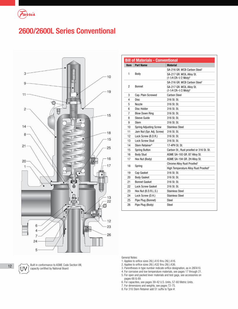
2600/2600L Series Conventional
Bill of Materials - ConventionalItem Part Name Material
1 BodySA-216 GR. WCB Carbon Steel1
SA-217 GR. WC6, Alloy St. (1-1⁄4 CR–1⁄2 Moly)2
2 BonnetSA-216 GR. WCB Carbon Steel1
SA-217 GR. WC6, Alloy St. (1-1⁄4 CR–1⁄2 Moly)2
3 Cap. Plain Screwed Carbon Steel
4 Disc 316 St. St.
5 Nozzle 316 St. St.
6 Disc Holder 316 St. St.
7 Blow Down Ring 316 St. St.
8 Sleeve Guide 316 St. St.
9 Stem 316 St. St.
10 Spring Adjusting Screw Stainless Steel
11 Jam Nut (Spr. Adj. Screw) 316 St. St.
12 Lock Screw (B.D.R.) 316 St. St.
13 Lock Screw Stud 316 St. St.
14 Stem Retainer8 17-4PH St. St.
15 Spring Button Carbon St., Rust proofed or 316 St. St.
16 Body Stud ASME SA-193 GR. B7 Alloy St.
17 Hex Nut (Body) ASME SA-194 GR. 2H Alloy St.
18 SpringChrome Alloy Rust Proofed1
High Temperature Alloy Rust Proofed2
19 Cap Gasket 316 St. St.
20 Body Gasket 316 St. St.
21 Bonnet Gasket 316 St. St.
22 Lock Screw Gasket 316 St. St.
23 Hex Nut (B.D.R.L.S.) Stainless Steel
24 Lock Screw (D.H.) Stainless Steel
25 Pipe Plug (Bonnet) Steel
26 Pipe Plug (Body) Steel
Built in conformance to ASME Code Section VIII,
capacity certified by National Board
General Notes:
1. Applies to orifice sizes 26( ) A10 thru 26( ) A16.
2. Applies to orifice sizes 26( ) A32 thru 26( ) A36.
3. Parentheses in type number indicate orifice designation, as in 26FA10.
4. For corrosive and low temperature materials, see pages 17 through 21.
5. For open and packed lever materials and test gags, see accessories on
pages 68 & 69.
6. For capacities, see pages 39-42 U.S. Units, 57-60 Metric Units.
7. For dimensions and weights, see pages 72-75.
8. For 316 Stem Retainer add S1 suffix to Type #.
13
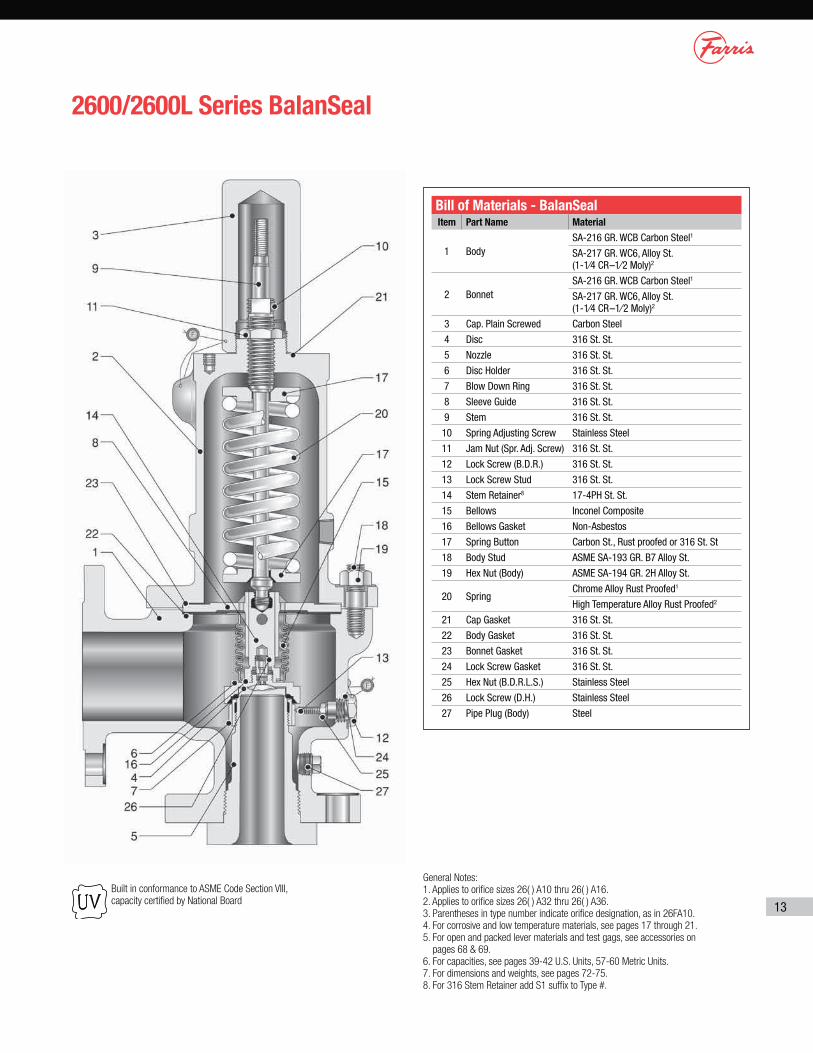
2600/2600L Series BalanSeal
Built in conformance to ASME Code Section VIII,
capacity certified by National Board
General Notes:
1. Applies to orifice sizes 26( ) A10 thru 26( ) A16.
2. Applies to orifice sizes 26( ) A32 thru 26( ) A36.
3. Parentheses in type number indicate orifice designation, as in 26FA10.
4. For corrosive and low temperature materials, see pages 17 through 21.
5. For open and packed lever materials and test gags, see accessories on
pages 68 & 69.
6. For capacities, see pages 39-42 U.S. Units, 57-60 Metric Units.
7. For dimensions and weights, see pages 72-75.
8. For 316 Stem Retainer add S1 suffix to Type #.
Bill of Materials - BalanSealItem Part Name Material
1 BodySA-216 GR. WCB Carbon Steel1
SA-217 GR. WC6, Alloy St. (1-1⁄4 CR–1⁄2 Moly)2
2 BonnetSA-216 GR. WCB Carbon Steel1
SA-217 GR. WC6, Alloy St. (1-1⁄4 CR–1⁄2 Moly)2
3 Cap. Plain Screwed Carbon Steel
4 Disc 316 St. St.
5 Nozzle 316 St. St.
6 Disc Holder 316 St. St.
7 Blow Down Ring 316 St. St.
8 Sleeve Guide 316 St. St.
9 Stem 316 St. St.
10 Spring Adjusting Screw Stainless Steel
11 Jam Nut (Spr. Adj. Screw) 316 St. St.
12 Lock Screw (B.D.R.) 316 St. St.
13 Lock Screw Stud 316 St. St.
14 Stem Retainer8 17-4PH St. St.
15 Bellows Inconel Composite
16 Bellows Gasket Non-Asbestos
17 Spring Button Carbon St., Rust proofed or 316 St. St
18 Body Stud ASME SA-193 GR. B7 Alloy St.
19 Hex Nut (Body) ASME SA-194 GR. 2H Alloy St.
20 SpringChrome Alloy Rust Proofed1
High Temperature Alloy Rust Proofed2
21 Cap Gasket 316 St. St.
22 Body Gasket 316 St. St.
23 Bonnet Gasket 316 St. St.
24 Lock Screw Gasket 316 St. St.
25 Hex Nut (B.D.R.L.S.) Stainless Steel
26 Lock Screw (D.H.) Stainless Steel
27 Pipe Plug (Body) Steel
14
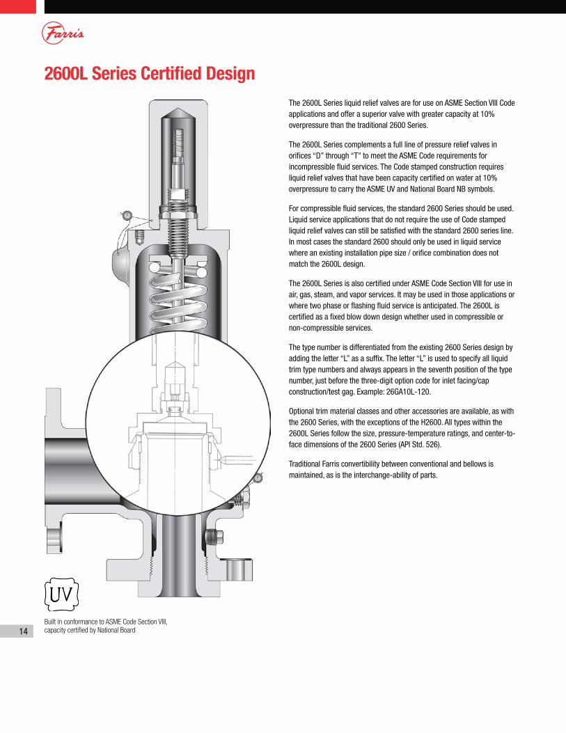
The 2600L Series liquid relief valves are for use on ASME Section VIII Code applications and offer a superior valve with greater capacity at 10% overpressure than the traditional 2600 Series.
The 2600L Series complements a full line of pressure relief valves in orifices “D” through “T” to meet the ASME Code requirements for incompressible fluid services. The Code stamped construction requires liquid relief valves that have been capacity certified on water at 10% overpressure to carry the ASME UV and National Board NB symbols.
For compressible fluid services, the standard 2600 Series should be used. Liquid service applications that do not require the use of Code stamped liquid relief valves can still be satisfied with the standard 2600 series line. In most cases the standard 2600 should only be used in liquid service where an existing installation pipe size / orifice combination does not match the 2600L design.
The 2600L Series is also certified under ASME Code Section VIII for use in air, gas, steam, and vapor services. It may be used in those applications or where two phase or flashing fluid service is anticipated. The 2600L is certified as a fixed blow down design whether used in compressible or non-compressible services.
The type number is differentiated from the existing 2600 Series design by adding the letter “L” as a suffix. The letter “L” is used to specify all liquid trim type numbers and always appears in the seventh position of the type number, just before the three-digit option code for inlet facing/cap construction/test gag. Example: 26GA10L-120.
Optional trim material classes and other accessories are available, as with the 2600 Series, with the exceptions of the H2600. All types within the 2600L Series follow the size, pressure-temperature ratings, and center-to-face dimensions of the 2600 Series (API Std. 526).
Traditional Farris convertibility between conventional and bellows is maintained, as is the interchange-ability of parts.
2600L Series Certified Design
Built in conformance to ASME Code Section VIII,
capacity certified by National Board
15
2600S Series Exposed Spring
Built in conformance to ASME Code Section VIII,
capacity certified by National Board
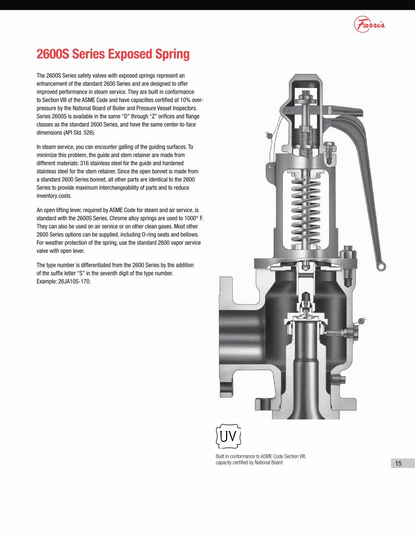
The 2600S Series safety valves with exposed springs represent an enhancement of the standard 2600 Series and are designed to offer improved performance in steam service. They are built in conformance to Section VIII of the ASME Code and have capacities certified at 10% over-pressure by the National Board of Boiler and Pressure Vessel Inspectors. Series 2600S is available in the same “D” through “Z” orifices and flange classes as the standard 2600 Series, and have the same center-to-face dimensions (API Std. 526).
In steam service, you can encounter galling of the guiding surfaces. To minimize this problem, the guide and stem retainer are made from different materials: 316 stainless steel for the guide and hardened stainless steel for the stem retainer. Since the open bonnet is made from a standard 2600 Series bonnet, all other parts are identical to the 2600 Series to provide maximum interchangeability of parts and to reduce inventory costs.
An open lifting lever, required by ASME Code for steam and air service, is standard with the 2600S Series. Chrome alloy springs are used to 1000° F. They can also be used on air service or on other clean gases. Most other 2600 Series options can be supplied, including O-ring seats and bellows. For weather protection of the spring, use the standard 2600 vapor service valve with open lever.
The type number is differentiated from the 2600 Series by the addition of the suffix letter “S” in the seventh digit of the type number. Example: 26JA10S-170.
16
2600/2600L Balanced Piston Design
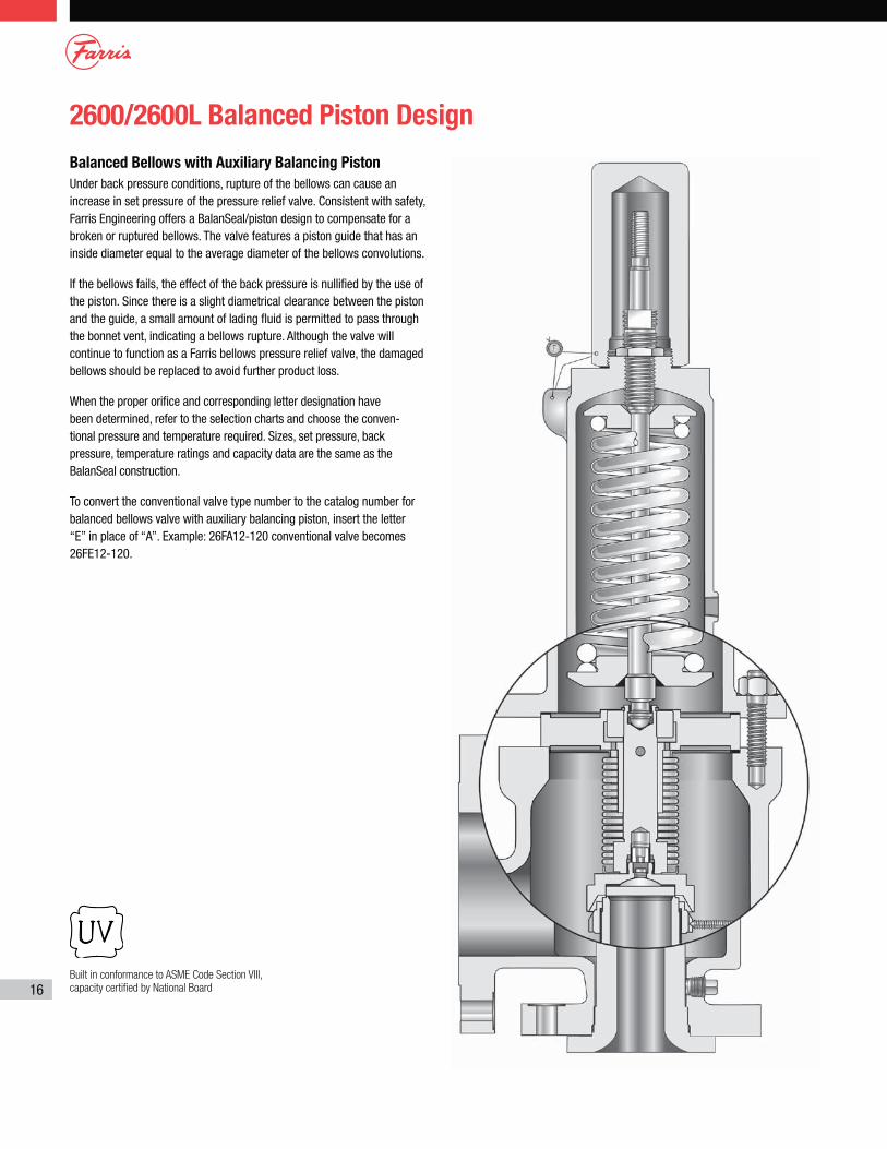
Balanced Bellows with Auxiliary Balancing Piston
Under back pressure conditions, rupture of the bellows can cause an increase in set pressure of the pressure relief valve. Consistent with safety, Farris Engineering offers a BalanSeal/piston design to compensate for a broken or ruptured bellows. The valve features a piston guide that has an inside diameter equal to the average diameter of the bellows convolutions.
If the bellows fails, the effect of the back pressure is nullified by the use of the piston. Since there is a slight diametrical clearance between the piston and the guide, a small amount of lading fluid is permitted to pass through the bonnet vent, indicating a bellows rupture. Although the valve will continue to function as a Farris bellows pressure relief valve, the damaged bellows should be replaced to avoid further product loss.
When the proper orifice and corresponding letter designa tion have been determined, refer to the selection charts and choose the conven- tional pressure and temperature required. Sizes, set pressure, back pressure, temperature ratings and capacity data are the same as the BalanSeal construction.
To convert the conventional valve type number to the catalog number for balanced bellows valve with auxiliary balancing piston, insert the letter “E” in place of “A”. Example: 26FA12-120 conventional valve becomes 26FE12-120.
Built in conformance to ASME Code Section VIII,
capacity certified by National Board
17
2600 Series Heat Transfer Fluid Service
Materials for Corrosive and Low Temperature Service
Built in conformance to ASME Code Section VIII,
capacity certified by National Board
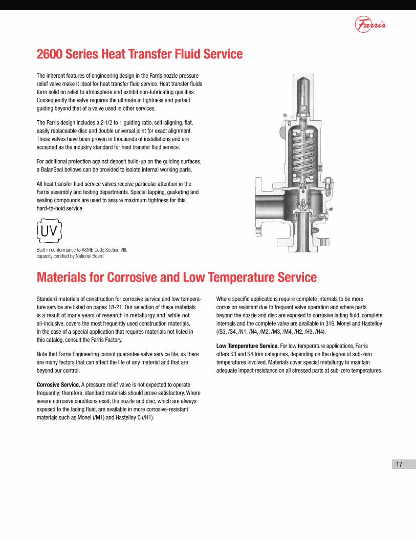
The inherent features of engineering design in the Farris nozzle pressure relief valve make it ideal for heat transfer fluid service. Heat transfer fluids form solid on relief to atmosphere and exhibit non-lubricating qualities. Consequently the valve requires the ultimate in tightness and perfect guiding beyond that of a valve used in other services.
The Farris design includes a 2-1/2 to 1 guiding ratio, self-aligning, flat, easily replaceable disc and double universal joint for exact alignment. These valves have been proven in thousands of installations and are accepted as the industry standard for heat transfer fluid service.
For additional protection against deposit build-up on the guiding surfaces, a BalanSeal bellows can be provided to isolate internal working parts.
All heat transfer fluid service valves receive particular attention in the Farris assembly and testing departments. Special lapping, gasketing and sealing compounds are used to assure maximum tightness for this hard-to-hold service.
Standard materials of construction for corrosive service and low tempera-ture service are listed on pages 18-21. Our selection of these materials is a result of many years of research in metallurgy and, while not all-inclusive, covers the most frequently used construction materials. In the case of a special application that requires materials not listed in this catalog, consult the Farris Factory.
Note that Farris Engineering cannot guarantee valve service life, as there are many factors that can affect the life of any material and that are beyond our control.
Corrosive Service. A pressure relief valve is not expected to operate frequently; therefore, standard materials should prove satisfactory. Where severe corrosive conditions exist, the nozzle and disc, which are always exposed to the lading fluid, are available in more corrosive-resistant materials such as Monel (/M1) and Hastelloy C (/H1).
Where specific applications require complete internals to be more corrosion resistant due to frequent valve operation and where parts beyond the nozzle and disc are exposed to corrosive lading fluid, complete internals and the complete valve are available in 316, Monel and Hastelloy (/S3, /S4, /N1, /N4, /M2, /M3, /M4, /H2, /H3, /H4).
Low Temperature Service. For low temperature applications, Farris offers S3 and S4 trim categories, depending on the degree of sub-zero temperatures involved. Materials cover special metallurgy to maintain adequate impact resistance on all stressed parts at sub-zero temperatures.
18
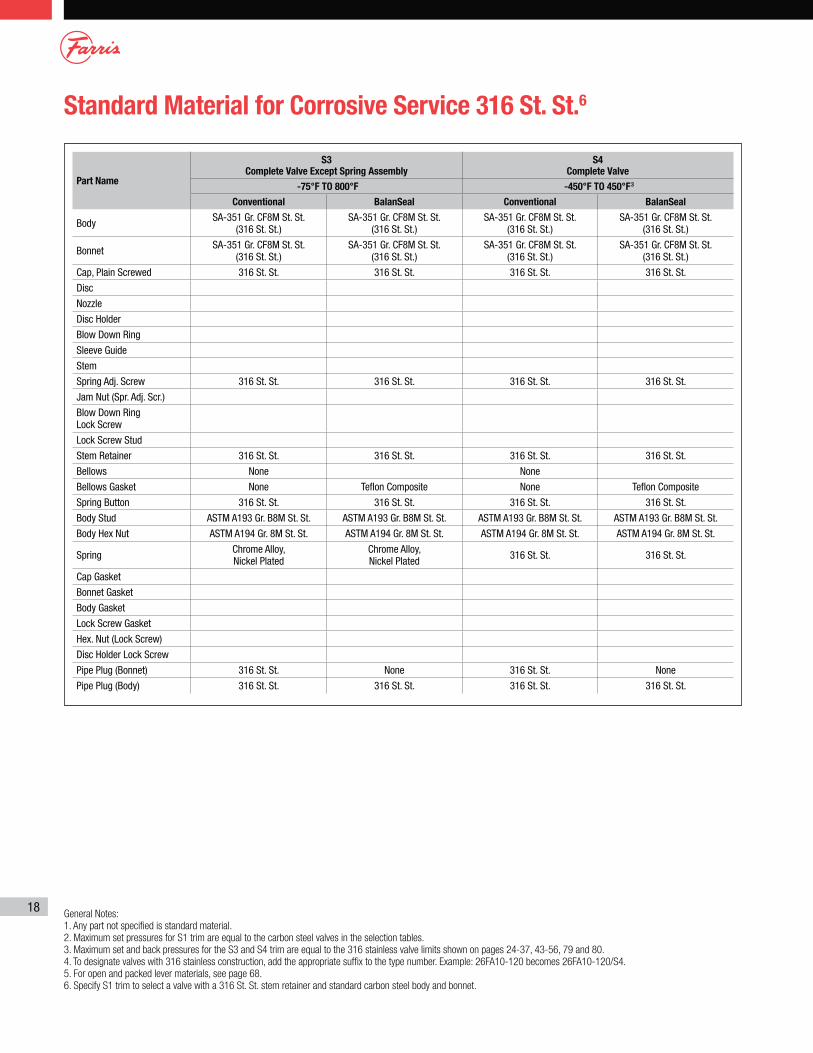
Standard Material for Corrosive Service 316 St. St.6
General Notes:
1. Any part not specified is standard material.
2. Maximum set pressures for S1 trim are equal to the carbon steel valves in the selection tables.
3. Maximum set and back pressures for the S3 and S4 trim are equal to the 316 stainless valve limits shown on pages 24-37, 43-56, 79 and 80.
4. To designate valves with 316 stainless construction, add the appropriate suffix to the type number. Example: 26FA10-120 becomes 26FA10-120/S4.
5. For open and packed lever materials, see page 68.
6. Specify S1 trim to select a valve with a 316 St. St. stem retainer and standard carbon steel body and bonnet.
Part Name
S3 Complete Valve Except Spring Assembly
S4 Complete Valve
-75°F TO 800°F -450°F TO 450°F3
Conventional BalanSeal Conventional BalanSeal
Body SA-351 Gr. CF8M St. St. (316 St. St.)
SA-351 Gr. CF8M St. St. (316 St. St.)
SA-351 Gr. CF8M St. St. (316 St. St.)
SA-351 Gr. CF8M St. St. (316 St. St.)
Bonnet SA-351 Gr. CF8M St. St. (316 St. St.)
SA-351 Gr. CF8M St. St. (316 St. St.)
SA-351 Gr. CF8M St. St. (316 St. St.)
SA-351 Gr. CF8M St. St. (316 St. St.)
Cap, Plain Screwed 316 St. St. 316 St. St. 316 St. St. 316 St. St.
Disc
Nozzle
Disc Holder
Blow Down Ring
Sleeve Guide
Stem
Spring Adj. Screw 316 St. St. 316 St. St. 316 St. St. 316 St. St.
Jam Nut (Spr. Adj. Scr.)
Blow Down Ring Lock Screw
Lock Screw Stud
Stem Retainer 316 St. St. 316 St. St. 316 St. St. 316 St. St.
Bellows None None
Bellows Gasket None Teflon Composite None Teflon Composite
Spring Button 316 St. St. 316 St. St. 316 St. St. 316 St. St.
Body Stud ASTM A193 Gr. B8M St. St. ASTM A193 Gr. B8M St. St. ASTM A193 Gr. B8M St. St. ASTM A193 Gr. B8M St. St.
Body Hex Nut ASTM A194 Gr. 8M St. St. ASTM A194 Gr. 8M St. St. ASTM A194 Gr. 8M St. St. ASTM A194 Gr. 8M St. St.
Spring Chrome Alloy, Nickel Plated
Chrome Alloy, Nickel Plated 316 St. St. 316 St. St.
Cap Gasket
Bonnet Gasket
Body Gasket
Lock Screw Gasket
Hex. Nut (Lock Screw)
Disc Holder Lock Screw
Pipe Plug (Bonnet) 316 St. St. None 316 St. St. None
Pipe Plug (Body) 316 St. St. 316 St. St. 316 St. St. 316 St. St.
19
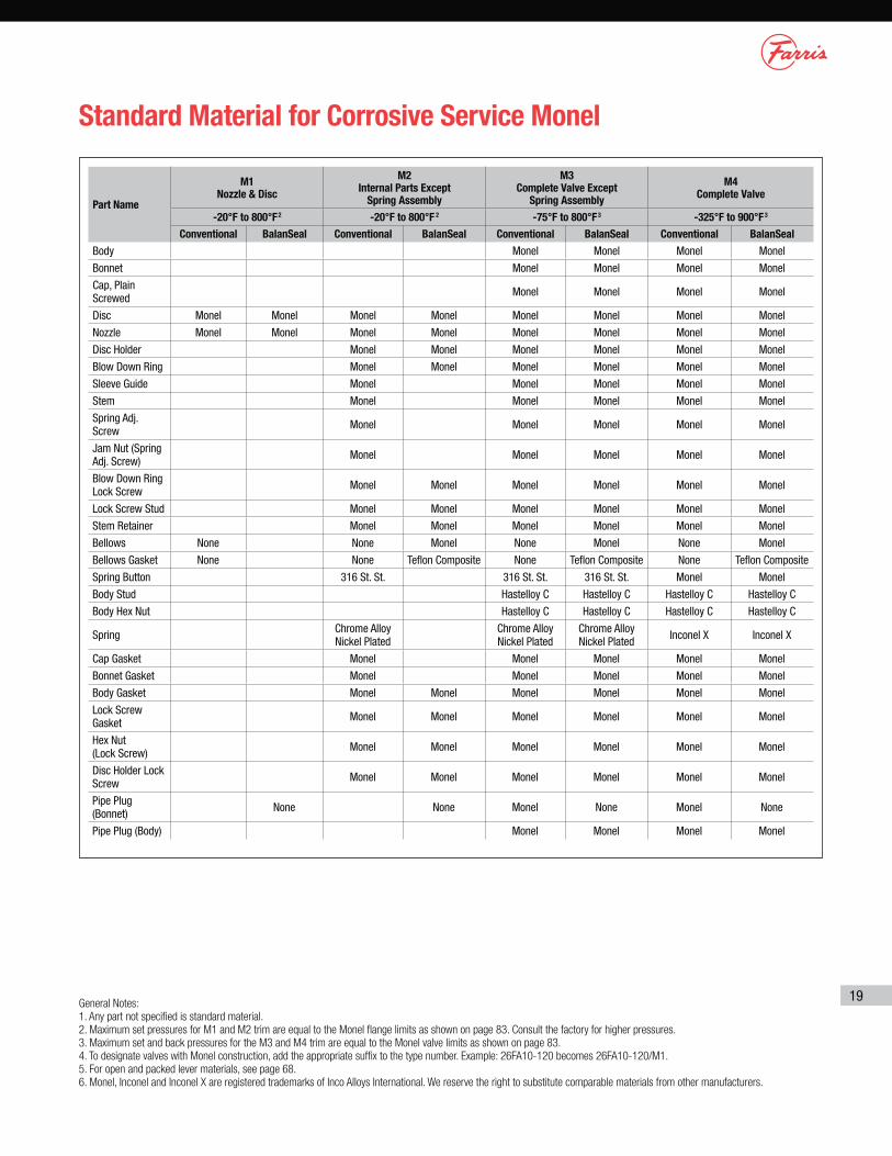
Standard Material for Corrosive Service Monel
General Notes:
1. Any part not specified is standard material.
2. Maximum set pressures for M1 and M2 trim are equal to the Monel flange limits as shown on page 83. Consult the factory for higher pressures.
3. Maximum set and back pressures for the M3 and M4 trim are equal to the Monel valve limits as shown on page 83.
4. To designate valves with Monel construction, add the appropriate suffix to the type number. Example: 26FA10-120 becomes 26FA10-120/M1.
5. For open and packed lever materials, see page 68.
6. Monel, Inconel and Inconel X are registered trademarks of Inco Alloys International. We reserve the right to substitute comparable materials from other manufacturers.
Part Name
M1 Nozzle & Disc
M2 Internal Parts Except
Spring Assembly
M3 Complete Valve Except
Spring Assembly
M4 Complete Valve
-20°F to 800°F2 -20°F to 800°F 2 -75°F to 800°F3 -325°F to 900°F3
Conventional BalanSeal Conventional BalanSeal Conventional BalanSeal Conventional BalanSeal
Body Monel Monel Monel Monel
Bonnet Monel Monel Monel Monel
Cap, Plain Screwed Monel Monel Monel Monel
Disc Monel Monel Monel Monel Monel Monel Monel Monel
Nozzle Monel Monel Monel Monel Monel Monel Monel Monel
Disc Holder Monel Monel Monel Monel Monel Monel
Blow Down Ring Monel Monel Monel Monel Monel Monel
Sleeve Guide Monel Monel Monel Monel Monel
Stem Monel Monel Monel Monel Monel
Spring Adj. Screw Monel Monel Monel Monel Monel
Jam Nut (Spring Adj. Screw) Monel Monel Monel Monel Monel
Blow Down Ring Lock Screw Monel Monel Monel Monel Monel Monel
Lock Screw Stud Monel Monel Monel Monel Monel Monel
Stem Retainer Monel Monel Monel Monel Monel Monel
Bellows None None Monel None Monel None Monel
Bellows Gasket None None Teflon Composite None Teflon Composite None Teflon Composite
Spring Button 316 St. St. 316 St. St. 316 St. St. Monel Monel
Body Stud Hastelloy C Hastelloy C Hastelloy C Hastelloy C
Body Hex Nut Hastelloy C Hastelloy C Hastelloy C Hastelloy C
Spring Chrome Alloy Nickel Plated
Chrome Alloy Nickel Plated
Chrome Alloy Nickel Plated Inconel X Inconel X
Cap Gasket Monel Monel Monel Monel Monel
Bonnet Gasket Monel Monel Monel Monel Monel
Body Gasket Monel Monel Monel Monel Monel Monel
Lock Screw Gasket Monel Monel Monel Monel Monel Monel
Hex Nut (Lock Screw) Monel Monel Monel Monel Monel Monel
Disc Holder Lock Screw Monel Monel Monel Monel Monel Monel
Pipe Plug (Bonnet) None None Monel None Monel None
Pipe Plug (Body) Monel Monel Monel Monel
20
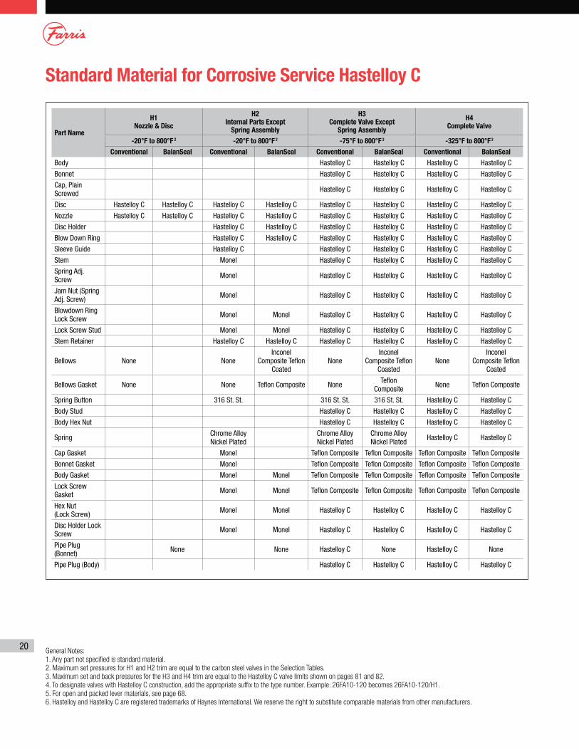
Standard Material for Corrosive Service Hastelloy C
General Notes:
1. Any part not specified is standard material.
2. Maximum set pressures for H1 and H2 trim are equal to the carbon steel valves in the Selection Tables.
3. Maximum set and back pressures for the H3 and H4 trim are equal to the Hastelloy C valve limits shown on pages 81 and 82.
4. To designate valves with Hastelloy C construction, add the appropriate suffix to the type number. Example: 26FA10-120 becomes 26FA10-120/H1.
5. For open and packed lever materials, see page 68.
6. Hastelloy and Hastelloy C are registered trademarks of Haynes International. We reserve the right to substitute comparable materials from other manufacturers.
Part Name
H1 Nozzle & Disc
H2 Internal Parts Except
Spring Assembly
H3 Complete Valve Except
Spring Assembly
H4 Complete Valve
-20°F to 800°F 2 -20°F to 800°F2 -75°F to 800°F3 -325°F to 800°F3
Conventional BalanSeal Conventional BalanSeal Conventional BalanSeal Conventional BalanSeal
Body Hastelloy C Hastelloy C Hastelloy C Hastelloy C
Bonnet Hastelloy C Hastelloy C Hastelloy C Hastelloy C
Cap, Plain Screwed Hastelloy C Hastelloy C Hastelloy C Hastelloy C
Disc Hastelloy C Hastelloy C Hastelloy C Hastelloy C Hastelloy C Hastelloy C Hastelloy C Hastelloy C
Nozzle Hastelloy C Hastelloy C Hastelloy C Hastelloy C Hastelloy C Hastelloy C Hastelloy C Hastelloy C
Disc Holder Hastelloy C Hastelloy C Hastelloy C Hastelloy C Hastelloy C Hastelloy C
Blow Down Ring Hastelloy C Hastelloy C Hastelloy C Hastelloy C Hastelloy C Hastelloy C
Sleeve Guide Hastelloy C Hastelloy C Hastelloy C Hastelloy C Hastelloy C
Stem Monel Hastelloy C Hastelloy C Hastelloy C Hastelloy C
Spring Adj. Screw Monel Hastelloy C Hastelloy C Hastelloy C Hastelloy C
Jam Nut (Spring Adj. Screw) Monel Hastelloy C Hastelloy C Hastelloy C Hastelloy C
Blowdown Ring Lock Screw Monel Monel Hastelloy C Hastelloy C Hastelloy C Hastelloy C
Lock Screw Stud Monel Monel Hastelloy C Hastelloy C Hastelloy C Hastelloy C
Stem Retainer Hastelloy C Hastelloy C Hastelloy C Hastelloy C Hastelloy C Hastelloy C
Bellows None NoneInconel
Composite Teflon Coated
NoneInconel
Composite Teflon Coasted
NoneInconel
Composite Teflon Coated
Bellows Gasket None None Teflon Composite None Teflon Composite None Teflon Composite
Spring Button 316 St. St. 316 St. St. 316 St. St. Hastelloy C Hastelloy C
Body Stud Hastelloy C Hastelloy C Hastelloy C Hastelloy C
Body Hex Nut Hastelloy C Hastelloy C Hastelloy C Hastelloy C
Spring Chrome Alloy Nickel Plated
Chrome Alloy Nickel Plated
Chrome Alloy Nickel Plated Hastelloy C Hastelloy C
Cap Gasket Monel Teflon Composite Teflon Composite Teflon Composite Teflon Composite
Bonnet Gasket Monel Teflon Composite Teflon Composite Teflon Composite Teflon Composite
Body Gasket Monel Monel Teflon Composite Teflon Composite Teflon Composite Teflon Composite
Lock Screw Gasket Monel Monel Teflon Composite Teflon Composite Teflon Composite Teflon Composite
Hex Nut (Lock Screw) Monel Monel Hastelloy C Hastelloy C Hastelloy C Hastelloy C
Disc Holder Lock Screw Monel Monel Hastelloy C Hastelloy C Hastelloy C Hastelloy C
Pipe Plug (Bonnet) None None Hastelloy C None Hastelloy C None
Pipe Plug (Body) Hastelloy C Hastelloy C Hastelloy C Hastelloy C
21
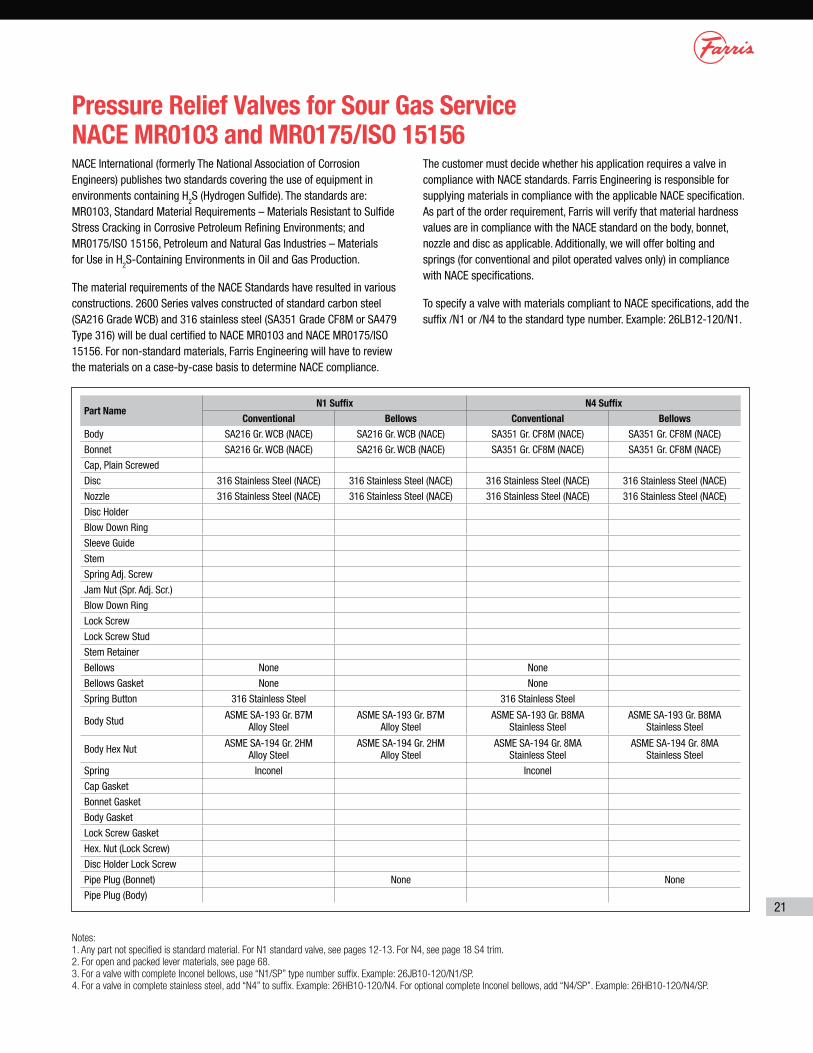
Pressure Relief Valves for Sour Gas Service NACE MR0103 and MR0175/ISO 15156
Notes:
1. Any part not specified is standard material. For N1 standard valve, see pages 12-13. For N4, see page 18 S4 trim.
2. For open and packed lever materials, see page 68.
3. For a valve with complete Inconel bellows, use “N1/SP” type number suffix. Example: 26JB10-120/N1/SP.
4. For a valve in complete stainless steel, add “N4” to suffix. Example: 26HB10-120/N4. For optional complete Inconel bellows, add “N4/SP”. Example: 26HB10-120/N4/SP.
NACE International (formerly The National Association of Corrosion Engineers) publishes two standards covering the use of equipment in environments containing H
2S (Hydrogen Sulfide). The standards are: MR0103, Standard Material Requirements – Materials Resistant to Sulfide Stress Cracking in Corrosive Petroleum Refining Environments; and MR0175/ISO 15156, Petroleum and Natural Gas Industries – Materials for Use in H
2S-Containing Environments in Oil and Gas Production.
The material requirements of the NACE Standards have resulted in various constructions. 2600 Series valves constructed of standard carbon steel (SA216 Grade WCB) and 316 stainless steel (SA351 Grade CF8M or SA479 Type 316) will be dual certified to NACE MR0103 and NACE MR0175/ISO 15156. For non-standard materials, Farris Engineering will have to review the materials on a case-by-case basis to determine NACE compliance.
The customer must decide whether his application requires a valve in compliance with NACE standards. Farris Engineering is responsible for supplying materials in compliance with the applicable NACE specification. As part of the order requirement, Farris will verify that material hardness values are in compliance with the NACE standard on the body, bonnet, nozzle and disc as applicable. Additionally, we will offer bolting and springs (for conventional and pilot operated valves only) in compliance with NACE specifications.
To specify a valve with materials compliant to NACE specifications, add the suffix /N1 or /N4 to the standard type number. Example: 26LB12-120/N1.
Part NameN1 Suffix N4 Suffix
Conventional Bellows Conventional Bellows
Body SA216 Gr. WCB (NACE) SA216 Gr. WCB (NACE) SA351 Gr. CF8M (NACE) SA351 Gr. CF8M (NACE)
Bonnet SA216 Gr. WCB (NACE) SA216 Gr. WCB (NACE) SA351 Gr. CF8M (NACE) SA351 Gr. CF8M (NACE)
Cap, Plain Screwed
Disc 316 Stainless Steel (NACE) 316 Stainless Steel (NACE) 316 Stainless Steel (NACE) 316 Stainless Steel (NACE)
Nozzle 316 Stainless Steel (NACE) 316 Stainless Steel (NACE) 316 Stainless Steel (NACE) 316 Stainless Steel (NACE)
Disc Holder
Blow Down Ring
Sleeve Guide
Stem
Spring Adj. Screw
Jam Nut (Spr. Adj. Scr.)
Blow Down Ring
Lock Screw
Lock Screw Stud
Stem Retainer
Bellows None None
Bellows Gasket None None
Spring Button 316 Stainless Steel 316 Stainless Steel
Body Stud ASME SA-193 Gr. B7M Alloy Steel
ASME SA-193 Gr. B7M Alloy Steel
ASME SA-193 Gr. B8MA Stainless Steel
ASME SA-193 Gr. B8MA Stainless Steel
Body Hex Nut ASME SA-194 Gr. 2HM Alloy Steel
ASME SA-194 Gr. 2HM Alloy Steel
ASME SA-194 Gr. 8MA Stainless Steel
ASME SA-194 Gr. 8MA Stainless Steel
Spring Inconel Inconel
Cap Gasket
Bonnet Gasket
Body Gasket
Lock Screw Gasket
Hex. Nut (Lock Screw)
Disc Holder Lock Screw
Pipe Plug (Bonnet) None None
Pipe Plug (Body)
22
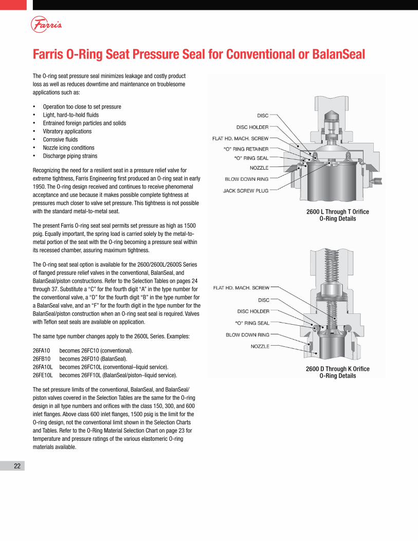
Farris O-Ring Seat Pressure Seal for Conventional or BalanSeal
The O-ring seat pressure seal minimizes leakage and costly product loss as well as reduces downtime and maintenance on troublesome applications such as:
• Operation too close to set pressure• Light, hard-to-hold fluids• Entrained foreign particles and solids• Vibratory applications• Corrosive fluids• Nozzle icing conditions• Discharge piping strains
Recognizing the need for a resilient seat in a pressure relief valve for extreme tightness, Farris Engineering first produced an O-ring seat in early 1950. The O-ring design received and continues to receive phenomenal acceptance and use because it makes possible complete tightness at pressures much closer to valve set pressure. This tightness is not possible with the standard metal-to-metal seat.
The present Farris O-ring seat seal permits set pressure as high as 1500 psig. Equally important, the spring load is carried solely by the metal-to-metal portion of the seat with the O-ring becoming a pressure seal within its recessed chamber, assuring maximum tightness.
The O-ring seat seal option is available for the 2600/2600L/2600S Series of flanged pressure relief valves in the conventional, BalanSeal, and BalanSeal/piston constructions. Refer to the Selection Tables on pages 24 through 37. Substitute a “C” for the fourth digit “A” in the type number for the conventional valve, a “D” for the fourth digit “B” in the type number for a BalanSeal valve, and an “F” for the fourth digit in the type number for the BalanSeal/piston construction when an O-ring seat seal is required. Valves with Teflon seat seals are available on application.
The same type number changes apply to the 2600L Series. Examples:
26FA10 becomes 26FC10 (conventional). 26FB10 becomes 26FD10 (BalanSeal). 26FA10L becomes 26FC10L (conventional–liquid service). 26FE10L becomes 26FF10L (BalanSeal/piston–liquid service).
The set pressure limits of the conventional, BalanSeal, and BalanSeal/piston valves covered in the Selection Tables are the same for the O-ring design in all type numbers and orifices with the class 150, 300, and 600 inlet flanges. Above class 600 inlet flanges, 1500 psig is the limit for the O-ring design, not the conventional limit shown in the Selection Charts and Tables. Refer to the O-Ring Material Selection Chart on page 23 for temperature and pressure ratings of the various elastomeric O-ring materials available.
2600 D Through K OrificeO-Ring Details
2600 L Through T OrificeO-Ring Details
23
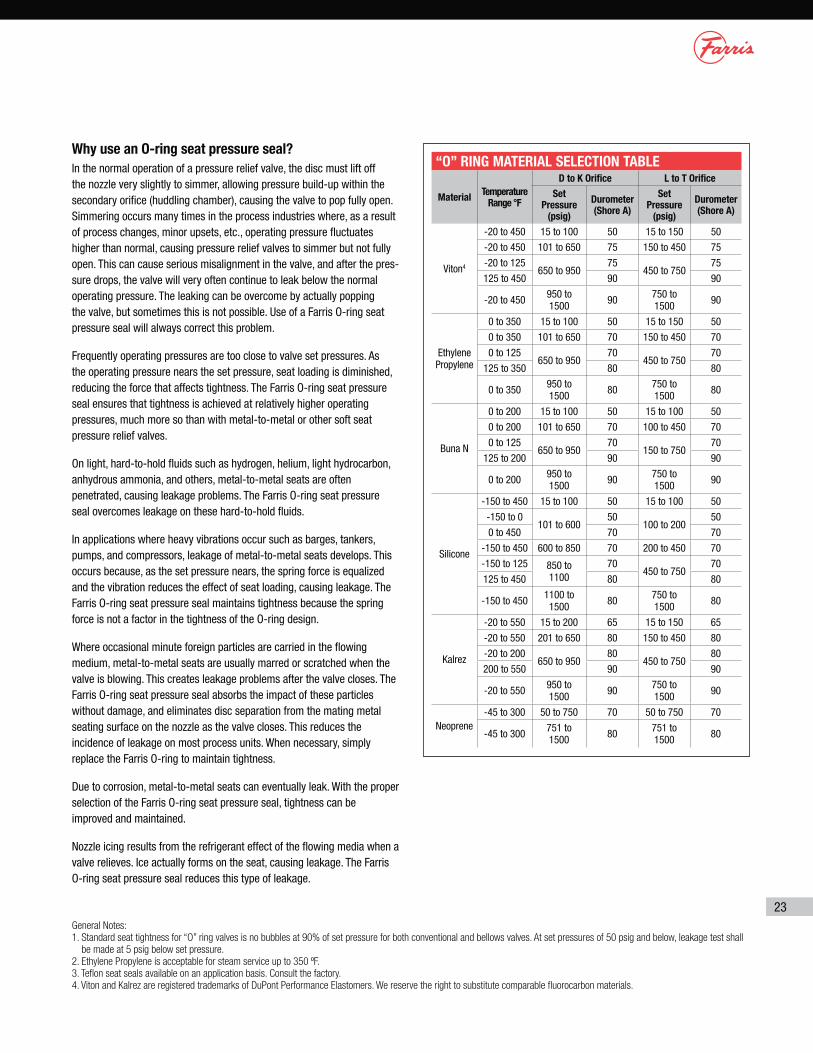
Why use an O-ring seat pressure seal?
In the normal operation of a pressure relief valve, the disc must lift off the nozzle very slightly to simmer, allowing pressure build-up within the secondary orifice (huddling chamber), causing the valve to pop fully open. Simmering occurs many times in the process industries where, as a result of process changes, minor upsets, etc., operating pressure fluctuates higher than normal, causing pressure relief valves to simmer but not fully open. This can cause serious misalignment in the valve, and after the pres-sure drops, the valve will very often continue to leak below the normal operating pressure. The leaking can be overcome by actually popping the valve, but sometimes this is not possible. Use of a Farris O-ring seat pressure seal will always correct this problem.
Frequently operating pressures are too close to valve set pressures. As the operating pressure nears the set pressure, seat loading is diminished, reducing the force that affects tightness. The Farris O-ring seat pressure seal ensures that tightness is achieved at relatively higher operating pressures, much more so than with metal-to-metal or other soft seat pressure relief valves.
On light, hard-to-hold fluids such as hydrogen, helium, light hydrocarbon, anhydrous ammonia, and others, metal-to-metal seats are often penetrated, causing leakage problems. The Farris O-ring seat pressure seal overcomes leakage on these hard-to-hold fluids.
In applications where heavy vibrations occur such as barges, tankers, pumps, and compressors, leakage of metal-to-metal seats develops. This occurs because, as the set pressure nears, the spring force is equalized and the vibration reduces the effect of seat loading, causing leakage. The Farris O-ring seat pressure seal maintains tightness because the spring force is not a factor in the tightness of the O-ring design.
Where occasional minute foreign particles are carried in the flowing medium, metal-to-metal seats are usually marred or scratched when the valve is blowing. This creates leakage problems after the valve closes. The Farris O-ring seat pressure seal absorbs the impact of these particles without damage, and eliminates disc separation from the mating metal seating surface on the nozzle as the valve closes. This reduces the incidence of leakage on most process units. When necessary, simply replace the Farris O-ring to maintain tightness.
Due to corrosion, metal-to-metal seats can eventually leak. With the proper selection of the Farris O-ring seat pressure seal, tightness can be improved and maintained.
Nozzle icing results from the refrigerant effect of the flowing media when a valve relieves. Ice actually forms on the seat, causing leakage. The Farris O-ring seat pressure seal reduces this type of leakage.
“O” RING MATERIAL SELECTION TABLE
MaterialTemperature
Range °F
D to K Orifice L to T Orifice
Set Pressure
(psig)
Durometer (Shore A)
Set Pressure
(psig)
Durometer (Shore A)
Viton4
-20 to 450 15 to 100 50 15 to 150 50
-20 to 450 101 to 650 75 150 to 450 75
-20 to 125650 to 950
75450 to 750
75
125 to 450 90 90
-20 to 450 950 to 1500 90 750 to
1500 90
Ethylene Propylene
0 to 350 15 to 100 50 15 to 150 50
0 to 350 101 to 650 70 150 to 450 70
0 to 125650 to 950
70450 to 750
70
125 to 350 80 80
0 to 350 950 to 1500 80 750 to
1500 80
Buna N
0 to 200 15 to 100 50 15 to 100 50
0 to 200 101 to 650 70 100 to 450 70
0 to 125650 to 950
70150 to 750
70
125 to 200 90 90
0 to 200 950 to 1500 90 750 to
1500 90
Silicone
-150 to 450 15 to 100 50 15 to 100 50
-150 to 0101 to 600
50100 to 200
50
0 to 450 70 70
-150 to 450 600 to 850 70 200 to 450 70
-150 to 125 850 to 1100
70450 to 750
70
125 to 450 80 80
-150 to 450 1100 to 1500 80 750 to
1500 80
Kalrez
-20 to 550 15 to 200 65 15 to 150 65
-20 to 550 201 to 650 80 150 to 450 80
-20 to 200650 to 950
80450 to 750
80
200 to 550 90 90
-20 to 550 950 to 1500 90 750 to
1500 90
Neoprene-45 to 300 50 to 750 70 50 to 750 70
-45 to 300 751 to 1500 80 751 to
1500 80
General Notes:
1. Standard seat tightness for “O” ring valves is no bubbles at 90% of set pressure for both conventional and bellows valves. At set pressures of 50 psig and below, leakage test shall
be made at 5 psig below set pressure.
2. Ethylene Propylene is acceptable for steam service up to 350 ºF.
3. Teflon seat seals available on an application basis. Consult the factory.
4. Viton and Kalrez are registered trademarks of DuPont Performance Elastomers. We reserve the right to substitute comparable fluorocarbon materials.
61
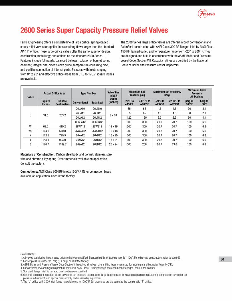
2600 Series Super Capacity Pressure Relief Valves
Farris Engineering offers a complete line of large orifice, spring-loaded safety relief valves for applications requiring flows larger than the standard API “T” orifice. These large orifice valves offer the same superior design, construction, metallurgy, and options as the standard 2600 Series. Features include full nozzle, balanced bellows, isolation of bonnet spring chamber, integral one-piece sleeve guide, temperature equalizing disc, and positive connection of internal parts. Six sizes with inlets ranging from 8" to 20" and effective orifice areas from 31.5 to 176.7 square inches are available.
The 2600 Series large orifice valves are offered in both conventional and BalanSeal construction with ANSI Class 300 RF flanged inlet by ANSI Class 150 RF flanged outlet, and temperature range from -20° to 800° F. They are designed and built in accordance with the ASME Boiler and Pressure Vessel Code, Section VIII. Capacity ratings are certified by the National Board of Boiler and Pressure Vessel Inspectors.
General Notes:
1. All valves supplied with plain caps unless otherwise specified. Standard suffix for type number is “-120”. For other cap construction, refer to page 69.
2. For set pressures under 20 psig (1.4 barg) consult the factory.
3. ASME Boiler and Pressure Vessel Code Section VIII requires all valves have a lifting lever when used for air, steam and hot water (over 140°F).
4. For corrosive, low and high temperature materials, ANSI Class 150 inlet flange and open bonnet designs, consult the Factory.
5. Standard flange finish is serrated unless otherwise specified.
6. Optional equipment includes: air set device for set pressure testing, extra large lapping glass for valve seat maintenance, spring compression device for set
pressure adjustment, and special disassembly and reassembly equipment.
7. The “U” orifice with 300# inlet flange is available up to 1000°F. Set pressures are the same as the comparable “T” orifice.
Materials of Construction: Carbon steel body and bonnet, stainless steel trim and chrome alloy spring. Other materials available on application. Consult the factory.
Connections: ANSI Class 300#RF inlet x 150#RF. Other connection types available on application. Consult the factory.
Orifice
Actual Orifice Area Type Number Valve Size Inlet X Outlet
(inches)
Maximum Set Pressure, psig
Maximum Set Pressure, barg
Maximum Back Pressure
All Designs
Square Inches
Square Centimeters
Conventional BalanSeal-20°F to +450°F
+451°F to +800°F
-29°C to +232°C
+233°C to +427°C
psig @ 100°F
barg @ 38°C
U 31.5 203.2
26UA10 26UB10
8 x 10
65 65 4.5 4.5 30 2.1
26UA11 26UB11 65 65 4.5 4.5 30 2.1
26UA12 26UB12 120 120 8.3 8.3 60 4.1
H26UA12 H26UB12 300 300 20.7 20.7 100 6.9
W 63.6 410.2 26WA12 26WB12 12 x 16 300 300 20.7 20.7 100 6.9
W2 104.0 670.8 26W2A12 26W2B12 16 x 18 300 300 20.7 20.7 100 6.9
X 113.1 729.5 26XA12 26XB12 16 x 20 300 300 20.7 20.7 100 6.9
Y 143.1 923.0 26YA12 26YB12 18 x 24 300 300 20.7 20.7 100 6.9
Z 176.7 1139.7 26ZA12 26ZB12 20 x 24 300 200 20.7 13.8 100 6.9

62
2600 Series Super Capacity Conventional
Bill of Materials–ConventionalItem Part Name Material
1 Body 26( )A12 ASTM A216 Gr. WCB. Carb. St.
2 Bonnet 26( )A12 ASTM A216 Gr. WCB. Carb. St.
3 Cap, Plain Screwed ASTM A216 Gr. WCB. Carb. St.
4 Disc Stainless Steel
5 Nozzle 316 St. St.
6 Disc Holder Stainless Steel
7 Blowdown Ring Stainless Steel
8 Sleeve Guide 26( )A12 Stainless Steel
9 Stem Stainless Steel
10 Spring Adjusting Screw Stainless Steel
11 Jam Nut (Spr. Adj. Screw) Stainless Steel
12 Lock Screw (B.D.R.) Stainless Steel
13 Lock Screw Stud Stainless Steel
14 Stem Retainer Stainless Steel
15 Spring Button, Lower Carbon St. Rust Proofed
16 Spring Button, Upper Carbon St. Rust Proofed
17* Insert, Spring Button Upper Stainless Steel
18 Stem Insert Stainless Steel
19* Retaining Ring Stainless Steel
20* Back-Up Ring Teflon
21* Cylinder Plug Stainless Steel
22* O-Ring, Cylinder Plug Ethylene Propylene
23 Body Stud ASTM A193 Gr. B7, Alloy St.
24 Hex Nut (Body) ASTM A194 Gr. 2H, Alloy St.
25 Spring 26( )A12 Chrome Alloy, Rust Proofed
26* Roller Thrust Bearing Hardened Alloy Steel
27 Cap Gasket Soft Iron or Steel
28 Body Gasket Soft Iron or Steel
29 Bonnet Gasket Soft Iron or Steel
30 Lock Screw Gasket Soft Iron or Steel
31 Hex Nut (B.D.R.L.S.) Stainless Steel
32 Lock Screw (D.H.) Stainless Steel
33 Pipe Plug (Bonnet) Steel
34 Pipe Plug (Body) Steel
35* Forged Eye Bolt Steel, Galvanized
*Not supplied on U & W orifice
Note: The “U” orifice weights and dimensions are identical to the “T” orifice on page 75.
Valve Size
Inlet X Outlet
ANSI Flange Class Type
Number Conv.
Dimensions, in/mm Approx. Weight Lbs/KgInlet
RFOutlet
RFA
(max.)B C E F
8 U 10 300 150 26UA12 54-1/2 1385
11 279
10-7/8 276
13/16 21
2-7/16 62
650 295
12 W 16 300 150 26WA12 70-1/2 1791
16 406
14-1/8 359
13/16 21
2-13/16 71
2800 1270
16 W2 18 300 150 26W2A12 90-3/4 2305
20 508
16 406
1-1/4 32
3-1/2 89
4200 1905
16 X 20 300 150 26XA12 93-1/2 2375
21 533
17 432
1-1/4 32
3-1/2 89
5500 2495
18 Y 24 300 150 26YA12 97-1/2 2477
25 635
20 508
1-1/4 32
3-5/8 92
7000 3175
20 Z 24 300 150 26ZA12 109 2769
25 635
20 508
1-1/4 32
3-3/4 95
7500 3402

63
2600 Series Super Capacity BalanSeal
*Not supplied on U & W orifice
Note: The “U” orifice weights and dimensions are identical to the “T” orifice on page 75.
Bill of Materials–BalanSealItem Part Name Material
1 Body 26( )B12 ASTM A216 Gr. WCB. Carb. St.
2 Bonnet 26( )B12 ASTM A216 Gr. WCB. Carb. St.
3 Cap, Plain Screwed ASTM A216 Gr. WCB. Carb. St.
4 Disc Stainless Steel
5 Nozzle 316 St. St.
6 Disc Holder Stainless Steel
7 Blowdown Ring Stainless Steel
8 Sleeve Guide 26( )B12 Stainless Steel
9 Stem Stainless Steel
10 Spring Adjusting Screw Stainless Steel
11 Jam Nut (Spr. Adj. Screw) Stainless Steel
12 Lock Screw (B.D.R.) Stainless Steel
13 Lock Screw Stud Stainless Steel
14 Stem Retainer Stainless Steel
15 Spring Button, Lower Carbon St. Rust Proofed
16 Spring Button, Upper Carbon St. Rust Proofed
17* Insert, Spring Button Upper Stainless Steel
18 Stem Insert Stainless Steel
19* Retaining Ring Stainless Steel
20* Back-Up Ring Teflon
21* Cylinder Plug Stainless Steel
22* O-Ring, Cylinder Plug Ethylene Propylene
23 Body Stud ASTM A193 Gr. B7, Alloy St.
24 Hex Nut (Body) ASTM A194 Gr. 2H, Alloy St.
25 Spring 26( )B12 Chrome Alloy, Rust Proofed
26* Roller Thrust Bearing Hardened Alloy Steel
27 Cap Gasket Soft Iron or Steel
28 Body Gasket Soft Iron or Steel
29 Bonnet Gasket Soft Iron or Steel
30 Lock Screw Gasket Soft Iron or Steel
31 Hex Nut (B.D.R.L.S.) Stainless Steel
32 Lock Screw (D.H.) Stainless Steel
33 Pipe Plug (Body) Steel
34 Bellows Inconel Composite
35* Bellows Gasket Flexible Graphite
36* Forged Eye Bolt Steel, Galvanized
Valve Size
Inlet X Outlet
ANSI Flange Class Type
Number Conv.
Dimensions, in/mm Approx. Weight Lbs/KgInlet
RFOutlet
RFA
(max.) B C E F
8 U 10 300 150 26UB12 54-1/2 1385
11 279
10-7/8 276
13/16 21
2-7/16 62
700 317
12 W 16 300 150 26WB12 70-1/2 1791
16 406
14-1/8 359
13/16 21
2-13/16 71
2850 1293
16 W2 18 300 150 26W2B12 90-3/4
230520 508
16 406
1-1/4 32
3-1/2 89
4250 1927
16 X 20 300 150 26XB12 93-1/2 2375
21 533
17 432
1-1/4 32
3-1/2 89
5550 2517
18 Y 24 300 150 26YB12 97-1/2 2477
25 635
20 508
1-1/4 32
3-5/8 92
7050 3197
20 Z 24 300 150 26ZB12 109 2769
25 635
20 508
1-1/4 32
3-3/4 95
7550 3424
64
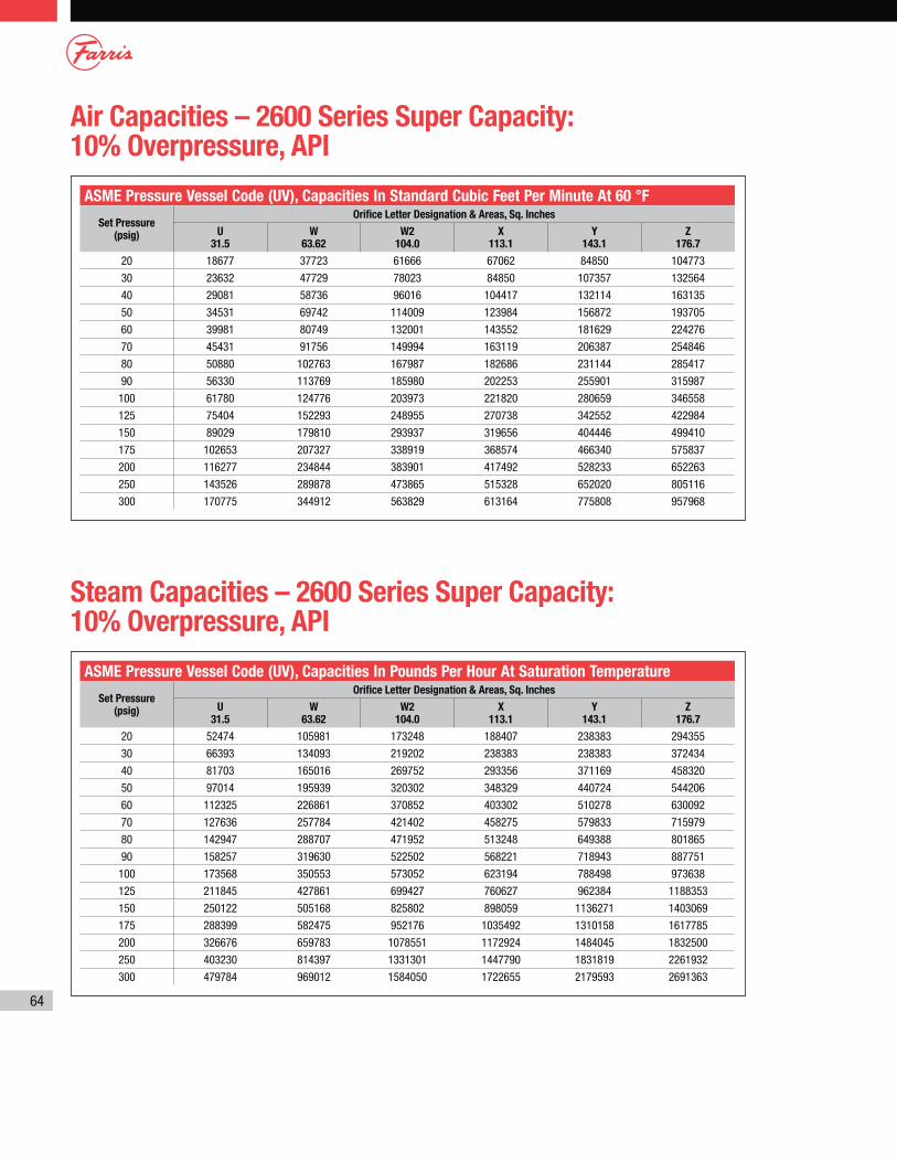
Air Capacities – 2600 Series Super Capacity: 10% Overpressure, API
Steam Capacities – 2600 Series Super Capacity: 10% Overpressure, API
ASME Pressure Vessel Code (UV), Capacities In Standard Cubic Feet Per Minute At 60 °F
Set Pressure (psig)
Orifice Letter Designation & Areas, Sq. Inches
U 31.5
W 63.62
W2 104.0
X 113.1
Y 143.1
Z 176.7
20 18677 37723 61666 67062 84850 104773
30 23632 47729 78023 84850 107357 132564
40 29081 58736 96016 104417 132114 163135
50 34531 69742 114009 123984 156872 193705
60 39981 80749 132001 143552 181629 224276
70 45431 91756 149994 163119 206387 254846
80 50880 102763 167987 182686 231144 285417
90 56330 113769 185980 202253 255901 315987
100 61780 124776 203973 221820 280659 346558
125 75404 152293 248955 270738 342552 422984
150 89029 179810 293937 319656 404446 499410
175 102653 207327 338919 368574 466340 575837
200 116277 234844 383901 417492 528233 652263
250 143526 289878 473865 515328 652020 805116
300 170775 344912 563829 613164 775808 957968
ASME Pressure Vessel Code (UV), Capacities In Pounds Per Hour At Saturation Temperature
Set Pressure (psig)
Orifice Letter Designation & Areas, Sq. Inches
U 31.5
W 63.62
W2 104.0
X 113.1
Y 143.1
Z 176.7
20 52474 105981 173248 188407 238383 294355
30 66393 134093 219202 238383 238383 372434
40 81703 165016 269752 293356 371169 458320
50 97014 195939 320302 348329 440724 544206
60 112325 226861 370852 403302 510278 630092
70 127636 257784 421402 458275 579833 715979
80 142947 288707 471952 513248 649388 801865
90 158257 319630 522502 568221 718943 887751
100 173568 350553 573052 623194 788498 973638
125 211845 427861 699427 760627 962384 1188353
150 250122 505168 825802 898059 1136271 1403069
175 288399 582475 952176 1035492 1310158 1617785
200 326676 659783 1078551 1172924 1484045 1832500
250 403230 814397 1331301 1447790 1831819 2261932
300 479784 969012 1584050 1722655 2179593 2691363
65
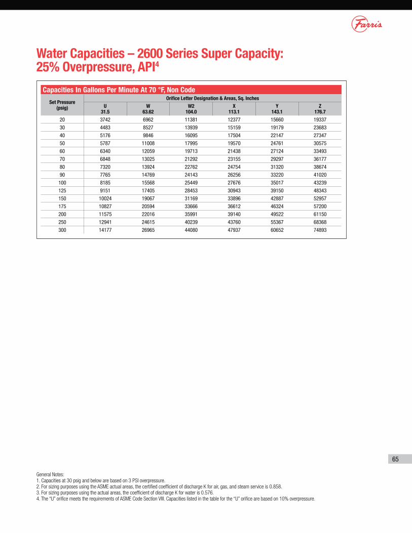
Water Capacities – 2600 Series Super Capacity: 25% Overpressure, API4
General Notes:
1. Capacities at 30 psig and below are based on 3 PSI overpressure.
2. For sizing purposes using the ASME actual areas, the certified coefficient of discharge K for air, gas, and steam service is 0.858.
3. For sizing purposes using the actual areas, the coefficient of discharge K for water is 0.576.
4. The “U” orifice meets the requirements of ASME Code Section VIII. Capacities listed in the table for the “U” orifice are based on 10% overpressure.
Capacities In Gallons Per Minute At 70 °F, Non Code
Set Pressure (psig)
Orifice Letter Designation & Areas, Sq. Inches
U 31.5
W 63.62
W2 104.0
X 113.1
Y 143.1
Z 176.7
20 3742 6962 11381 12377 15660 19337
30 4483 8527 13939 15159 19179 23683
40 5176 9846 16095 17504 22147 27347
50 5787 11008 17995 19570 24761 30575
60 6340 12059 19713 21438 27124 33493
70 6848 13025 21292 23155 29297 36177
80 7320 13924 22762 24754 31320 38674
90 7765 14769 24143 26256 33220 41020
100 8185 15568 25449 27676 35017 43239
125 9151 17405 28453 30943 39150 48343
150 10024 19067 31169 33896 42887 52957
175 10827 20594 33666 36612 46324 57200
200 11575 22016 35991 39140 49522 61150
250 12941 24615 40239 43760 55367 68368
300 14177 26965 44080 47937 60652 74893
72
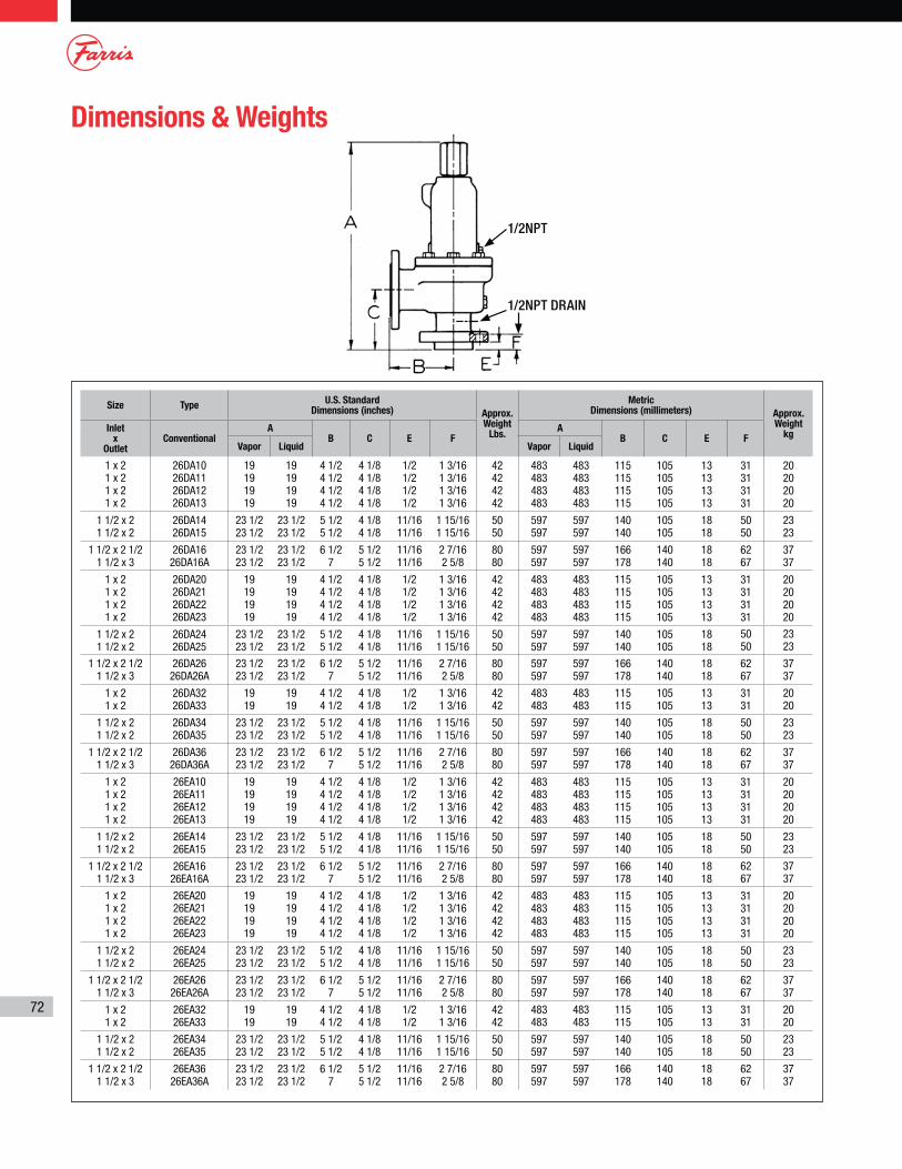
Dimensions & Weights
Size TypeU.S. Standard
Dimensions (inches) Approx. Weight
Lbs.
Metric Dimensions (millimeters) Approx.
Weight kg
Inlet x
OutletConventional
AB C E F
AB C E F
Vapor Liquid Vapor Liquid
1 x 2 1 x 2 1 x 2 1 x 2
26DA10 26DA11 26DA12 26DA13
19 19 19 19
19 19 19 19
4 1/2 4 1/2 4 1/2 4 1/2
4 1/8 4 1/8 4 1/8 4 1/8
1/2 1/2 1/2 1/2
1 3/16 1 3/16 1 3/16 1 3/16
42 42 42 42
483 483 483 483
483 483 483 483
115 115 115 115
105 105 105 105
13 13 13 13
31 31 31 31
20 20 20 20
1 1/2 x 2 1 1/2 x 2
26DA14 26DA15
23 1/2 23 1/2
23 1/2 23 1/2
5 1/2 5 1/2
4 1/8 4 1/8
11/16 11/16
1 15/16 1 15/16
50 50
597 597
597 597
140 140
105 105
18 18
50 50
23 23
1 1/2 x 2 1/2 1 1/2 x 3
26DA16 26DA16A
23 1/2 23 1/2
23 1/2 23 1/2
6 1/2 7
5 1/2 5 1/2
11/16 11/16
2 7/16 2 5/8
80 80
597 597
597 597
166 178
140 140
18 18
62 67
37 37
1 x 2 1 x 2 1 x 2 1 x 2
26DA20 26DA21 26DA22 26DA23
19 19 19 19
19 19 19 19
4 1/2 4 1/2 4 1/2 4 1/2
4 1/8 4 1/8 4 1/8 4 1/8
1/2 1/2 1/2 1/2
1 3/16 1 3/16 1 3/16 1 3/16
42 42 42 42
483 483 483 483
483 483 483 483
115 115 115 115
105 105 105 105
13 13 13 13
31 31 31 31
20 20 20 20
1 1/2 x 2 1 1/2 x 2
26DA24 26DA25
23 1/2 23 1/2
23 1/2 23 1/2
5 1/2 5 1/2
4 1/8 4 1/8
11/16 11/16
1 15/16 1 15/16
50 50
597 597
597 597
140 140
105 105
18 18
50 50
23 23
1 1/2 x 2 1/2 1 1/2 x 3
26DA26 26DA26A
23 1/2 23 1/2
23 1/2 23 1/2
6 1/2 7
5 1/2 5 1/2
11/16 11/16
2 7/16 2 5/8
80 80
597 597
597 597
166 178
140 140
18 18
62 67
37 37
1 x 2 1 x 2
26DA32 26DA33
19 19
19 19
4 1/2 4 1/2
4 1/8 4 1/8
1/2 1/2
1 3/16 1 3/16
42 42
483 483
483 483
115 115
105 105
13 13
31 31
20 20
1 1/2 x 2 1 1/2 x 2
26DA34 26DA35
23 1/2 23 1/2
23 1/2 23 1/2
5 1/2 5 1/2
4 1/8 4 1/8
11/16 11/16
1 15/16 1 15/16
50 50
597 597
597 597
140 140
105 105
18 18
50 50
23 23
1 1/2 x 2 1/2 1 1/2 x 3
26DA36 26DA36A
23 1/2 23 1/2
23 1/2 23 1/2
6 1/2 7
5 1/2 5 1/2
11/16 11/16
2 7/16 2 5/8
80 80
597 597
597 597
166 178
140 140
18 18
62 67
37 37
1 x 2 1 x 2 1 x 2 1 x 2
26EA10 26EA11 26EA12 26EA13
19 19 19 19
19 19 19 19
4 1/2 4 1/2 4 1/2 4 1/2
4 1/8 4 1/8 4 1/8 4 1/8
1/2 1/2 1/2 1/2
1 3/16 1 3/16 1 3/16 1 3/16
42 42 42 42
483 483 483 483
483 483 483 483
115 115 115 115
105 105 105 105
13 13 13 13
31 31 31 31
20 20 20 20
1 1/2 x 2 1 1/2 x 2
26EA14 26EA15
23 1/2 23 1/2
23 1/2 23 1/2
5 1/2 5 1/2
4 1/8 4 1/8
11/16 11/16
1 15/16 1 15/16
50 50
597 597
597 597
140 140
105 105
18 18
50 50
23 23
1 1/2 x 2 1/2 1 1/2 x 3
26EA16 26EA16A
23 1/2 23 1/2
23 1/2 23 1/2
6 1/2 7
5 1/2 5 1/2
11/16 11/16
2 7/16 2 5/8
80 80
597 597
597 597
166 178
140 140
18 18
62 67
37 37
1 x 2 1 x 2 1 x 2 1 x 2
26EA20 26EA21 26EA22 26EA23
19 19 19 19
19 19 19 19
4 1/2 4 1/2 4 1/2 4 1/2
4 1/8 4 1/8 4 1/8 4 1/8
1/2 1/2 1/2 1/2
1 3/16 1 3/16 1 3/16 1 3/16
42 42 42 42
483 483 483 483
483 483 483 483
115 115 115 115
105 105 105 105
13 13 13 13
31 31 31 31
20 20 20 20
1 1/2 x 2 1 1/2 x 2
26EA24 26EA25
23 1/2 23 1/2
23 1/2 23 1/2
5 1/2 5 1/2
4 1/8 4 1/8
11/16 11/16
1 15/16 1 15/16
50 50
597 597
597 597
140 140
105 105
18 18
50 50
23 23
1 1/2 x 2 1/2 1 1/2 x 3
26EA26 26EA26A
23 1/2 23 1/2
23 1/2 23 1/2
6 1/2 7
5 1/2 5 1/2
11/16 11/16
2 7/16 2 5/8
80 80
597 597
597 597
166 178
140 140
18 18
62 67
37 37
1 x 2 1 x 2
26EA32 26EA33
19 19
19 19
4 1/2 4 1/2
4 1/8 4 1/8
1/2 1/2
1 3/16 1 3/16
42 42
483 483
483 483
115 115
105 105
13 13
31 31
20 20
1 1/2 x 2 1 1/2 x 2
26EA34 26EA35
23 1/2 23 1/2
23 1/2 23 1/2
5 1/2 5 1/2
4 1/8 4 1/8
11/16 11/16
1 15/16 1 15/16
50 50
597 597
597 597
140 140
105 105
18 18
50 50
23 23
1 1/2 x 2 1/2 1 1/2 x 3
26EA36 26EA36A
23 1/2 23 1/2
23 1/2 23 1/2
6 1/2 7
5 1/2 5 1/2
11/16 11/16
2 7/16 2 5/8
80 80
597 597
597 597
166 178
140 140
18 18
62 67
37 37
1/2NPT
1/2NPT DRAIN
73
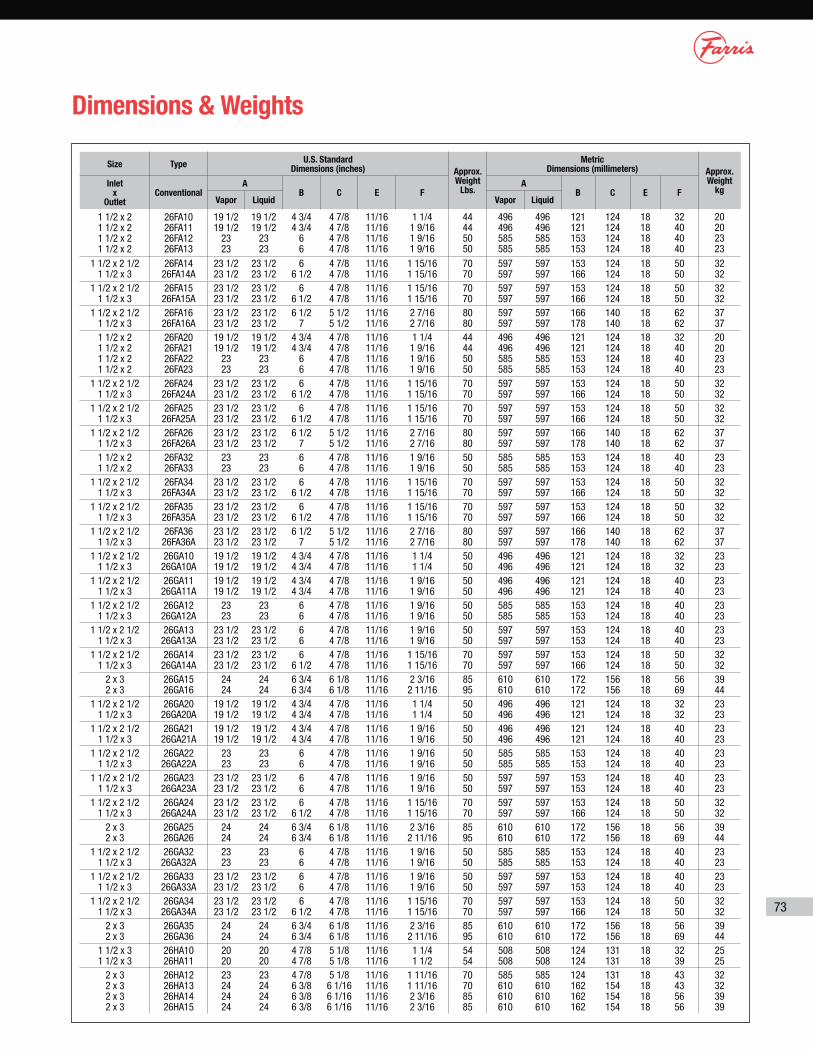
Dimensions & Weights
Size TypeU.S. Standard
Dimensions (inches) Approx. Weight
Lbs.
Metric Dimensions (millimeters) Approx.
Weight kg
Inlet x
OutletConventional
AB C E F
AB C E F
Vapor Liquid Vapor Liquid
1 1/2 x 2 1 1/2 x 2 1 1/2 x 2 1 1/2 x 2
26FA10 26FA11 26FA12 26FA13
19 1/2 19 1/2
23 23
19 1/2 19 1/2
23 23
4 3/4 4 3/4
6 6
4 7/8 4 7/8 4 7/8 4 7/8
11/16 11/16 11/16 11/16
1 1/4 1 9/16 1 9/16 1 9/16
44 44 50 50
496 496 585 585
496 496 585 585
121 121 153 153
124 124 124 124
18 18 18 18
32 40 40 40
20 20 23 23
1 1/2 x 2 1/2 1 1/2 x 3
26FA14 26FA14A
23 1/2 23 1/2
23 1/2 23 1/2
6 6 1/2
4 7/8 4 7/8
11/16 11/16
1 15/16 1 15/16
70 70
597 597
597 597
153 166
124 124
18 18
50 50
32 32
1 1/2 x 2 1/2 1 1/2 x 3
26FA15 26FA15A
23 1/2 23 1/2
23 1/2 23 1/2
6 6 1/2
4 7/8 4 7/8
11/16 11/16
1 15/16 1 15/16
70 70
597 597
597 597
153 166
124 124
18 18
50 50
32 32
1 1/2 x 2 1/2 1 1/2 x 3
26FA16 26FA16A
23 1/2 23 1/2
23 1/2 23 1/2
6 1/2 7
5 1/2 5 1/2
11/16 11/16
2 7/16 2 7/16
80 80
597 597
597 597
166 178
140 140
18 18
62 62
37 37
1 1/2 x 2 1 1/2 x 2 1 1/2 x 2 1 1/2 x 2
26FA20 26FA21 26FA22 26FA23
19 1/2 19 1/2
23 23
19 1/2 19 1/2
23 23
4 3/4 4 3/4
6 6
4 7/8 4 7/8 4 7/8 4 7/8
11/16 11/16 11/16 11/16
1 1/4 1 9/16 1 9/16 1 9/16
44 44 50 50
496 496 585 585
496 496 585 585
121 121 153 153
124 124 124 124
18 18 18 18
32 40 40 40
20 20 23 23
1 1/2 x 2 1/2 1 1/2 x 3
26FA24 26FA24A
23 1/2 23 1/2
23 1/2 23 1/2
6 6 1/2
4 7/8 4 7/8
11/16 11/16
1 15/16 1 15/16
70 70
597 597
597 597
153 166
124 124
18 18
50 50
32 32
1 1/2 x 2 1/2 1 1/2 x 3
26FA25 26FA25A
23 1/2 23 1/2
23 1/2 23 1/2
6 6 1/2
4 7/8 4 7/8
11/16 11/16
1 15/16 1 15/16
70 70
597 597
597 597
153 166
124 124
18 18
50 50
32 32
1 1/2 x 2 1/2 1 1/2 x 3
26FA26 26FA26A
23 1/2 23 1/2
23 1/2 23 1/2
6 1/2 7
5 1/2 5 1/2
11/16 11/16
2 7/16 2 7/16
80 80
597 597
597 597
166 178
140 140
18 18
62 62
37 37
1 1/2 x 2 1 1/2 x 2
26FA32 26FA33
23 23
23 23
6 6
4 7/8 4 7/8
11/16 11/16
1 9/16 1 9/16
50 50
585 585
585 585
153 153
124 124
18 18
40 40
23 23
1 1/2 x 2 1/2 1 1/2 x 3
26FA34 26FA34A
23 1/2 23 1/2
23 1/2 23 1/2
6 6 1/2
4 7/8 4 7/8
11/16 11/16
1 15/16 1 15/16
70 70
597 597
597 597
153 166
124 124
18 18
50 50
32 32
1 1/2 x 2 1/2 1 1/2 x 3
26FA35 26FA35A
23 1/2 23 1/2
23 1/2 23 1/2
6 6 1/2
4 7/8 4 7/8
11/16 11/16
1 15/16 1 15/16
70 70
597 597
597 597
153 166
124 124
18 18
50 50
32 32
1 1/2 x 2 1/2 1 1/2 x 3
26FA36 26FA36A
23 1/2 23 1/2
23 1/2 23 1/2
6 1/2 7
5 1/2 5 1/2
11/16 11/16
2 7/16 2 7/16
80 80
597 597
597 597
166 178
140 140
18 18
62 62
37 37
1 1/2 x 2 1/2 1 1/2 x 3
26GA10 26GA10A
19 1/2 19 1/2
19 1/2 19 1/2
4 3/4 4 3/4
4 7/8 4 7/8
11/16 11/16
1 1/4 1 1/4
50 50
496 496
496 496
121 121
124 124
18 18
32 32
23 23
1 1/2 x 2 1/2 1 1/2 x 3
26GA11 26GA11A
19 1/2 19 1/2
19 1/2 19 1/2
4 3/4 4 3/4
4 7/8 4 7/8
11/16 11/16
1 9/16 1 9/16
50 50
496 496
496 496
121 121
124 124
18 18
40 40
23 23
1 1/2 x 2 1/2 1 1/2 x 3
26GA12 26GA12A
23 23
23 23
6 6
4 7/8 4 7/8
11/16 11/16
1 9/16 1 9/16
50 50
585 585
585 585
153 153
124 124
18 18
40 40
23 23
1 1/2 x 2 1/2 1 1/2 x 3
26GA13 26GA13A
23 1/2 23 1/2
23 1/2 23 1/2
6 6
4 7/8 4 7/8
11/16 11/16
1 9/16 1 9/16
50 50
597 597
597 597
153 153
124 124
18 18
40 40
23 23
1 1/2 x 2 1/2 1 1/2 x 3
26GA14 26GA14A
23 1/2 23 1/2
23 1/2 23 1/2
6 6 1/2
4 7/8 4 7/8
11/16 11/16
1 15/16 1 15/16
70 70
597 597
597 597
153 166
124 124
18 18
50 50
32 32
2 x 3 2 x 3
26GA15 26GA16
24 24
24 24
6 3/4 6 3/4
6 1/8 6 1/8
11/16 11/16
2 3/16 2 11/16
85 95
610 610
610 610
172 172
156 156
18 18
56 69
39 44
1 1/2 x 2 1/2 1 1/2 x 3
26GA20 26GA20A
19 1/2 19 1/2
19 1/2 19 1/2
4 3/4 4 3/4
4 7/8 4 7/8
11/16 11/16
1 1/4 1 1/4
50 50
496 496
496 496
121 121
124 124
18 18
32 32
23 23
1 1/2 x 2 1/2 1 1/2 x 3
26GA21 26GA21A
19 1/2 19 1/2
19 1/2 19 1/2
4 3/4 4 3/4
4 7/8 4 7/8
11/16 11/16
1 9/16 1 9/16
50 50
496 496
496 496
121 121
124 124
18 18
40 40
23 23
1 1/2 x 2 1/2 1 1/2 x 3
26GA22 26GA22A
23 23
23 23
6 6
4 7/8 4 7/8
11/16 11/16
1 9/16 1 9/16
50 50
585 585
585 585
153 153
124 124
18 18
40 40
23 23
1 1/2 x 2 1/2 1 1/2 x 3
26GA23 26GA23A
23 1/2 23 1/2
23 1/2 23 1/2
6 6
4 7/8 4 7/8
11/16 11/16
1 9/16 1 9/16
50 50
597 597
597 597
153 153
124 124
18 18
40 40
23 23
1 1/2 x 2 1/2 1 1/2 x 3
26GA24 26GA24A
23 1/2 23 1/2
23 1/2 23 1/2
6 6 1/2
4 7/8 4 7/8
11/16 11/16
1 15/16 1 15/16
70 70
597 597
597 597
153 166
124 124
18 18
50 50
32 32
2 x 3 2 x 3
26GA25 26GA26
24 24
24 24
6 3/4 6 3/4
6 1/8 6 1/8
11/16 11/16
2 3/16 2 11/16
85 95
610 610
610 610
172 172
156 156
18 18
56 69
39 44
1 1/2 x 2 1/2 1 1/2 x 3
26GA32 26GA32A
23 23
23 23
6 6
4 7/8 4 7/8
11/16 11/16
1 9/16 1 9/16
50 50
585 585
585 585
153 153
124 124
18 18
40 40
23 23
1 1/2 x 2 1/2 1 1/2 x 3
26GA33 26GA33A
23 1/2 23 1/2
23 1/2 23 1/2
6 6
4 7/8 4 7/8
11/16 11/16
1 9/16 1 9/16
50 50
597 597
597 597
153 153
124 124
18 18
40 40
23 23
1 1/2 x 2 1/2 1 1/2 x 3
26GA34 26GA34A
23 1/2 23 1/2
23 1/2 23 1/2
6 6 1/2
4 7/8 4 7/8
11/16 11/16
1 15/16 1 15/16
70 70
597 597
597 597
153 166
124 124
18 18
50 50
32 32
2 x 3 2 x 3
26GA35 26GA36
24 24
24 24
6 3/4 6 3/4
6 1/8 6 1/8
11/16 11/16
2 3/16 2 11/16
85 95
610 610
610 610
172 172
156 156
18 18
56 69
39 44
1 1/2 x 3 1 1/2 x 3
26HA10 26HA11
20 20
20 20
4 7/8 4 7/8
5 1/8 5 1/8
11/16 11/16
1 1/4 1 1/2
54 54
508 508
508 508
124 124
131 131
18 18
32 39
25 25
2 x 3 2 x 3 2 x 3 2 x 3
26HA12 26HA13 26HA14 26HA15
23 24 24 24
23 24 24 24
4 7/8 6 3/8 6 3/8 6 3/8
5 1/8 6 1/16 6 1/16 6 1/16
11/16 11/16 11/16 11/16
1 11/16 1 11/16 2 3/16 2 3/16
70 70 85 85
585 610 610 610
585 610 610 610
124 162 162 162
131 154 154 154
18 18 18 18
43 43 56 56
32 32 39 39
74
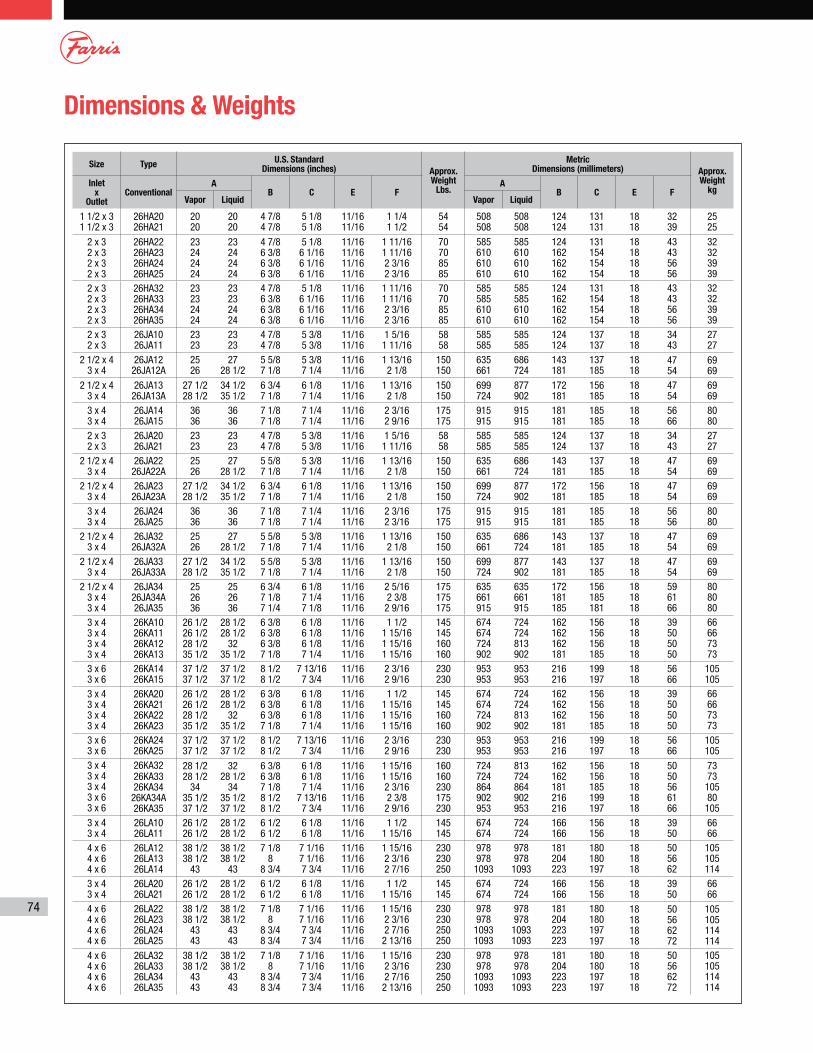
Dimensions & Weights
Size TypeU.S. Standard
Dimensions (inches) Approx. Weight
Lbs.
Metric Dimensions (millimeters) Approx.
Weight kg
Inlet x
OutletConventional
AB C E F
AB C E F
Vapor Liquid Vapor Liquid
1 1/2 x 3 1 1/2 x 3
26HA20 26HA21
20 20
20 20
4 7/8 4 7/8
5 1/8 5 1/8
11/16 11/16
1 1/4 1 1/2
54 54
508 508
508 508
124 124
131 131
18 18
32 39
25 25
2 x 3 2 x 3 2 x 3 2 x 3
26HA22 26HA23 26HA24 26HA25
23 24 24 24
23 24 24 24
4 7/8 6 3/8 6 3/8 6 3/8
5 1/8 6 1/16 6 1/16 6 1/16
11/16 11/16 11/16 11/16
1 11/16 1 11/16 2 3/16 2 3/16
70 70 85 85
585 610 610 610
585 610 610 610
124 162 162 162
131 154 154 154
18 18 18 18
43 43 56 56
32 32 39 39
2 x 3 2 x 3 2 x 3 2 x 3
26HA32 26HA33 26HA34 26HA35
23 23 24 24
23 23 24 24
4 7/8 6 3/8 6 3/8 6 3/8
5 1/8 6 1/16 6 1/16 6 1/16
11/16 11/16 11/16 11/16
1 11/16 1 11/16 2 3/16 2 3/16
70 70 85 85
585 585 610 610
585 585 610 610
124 162 162 162
131 154 154 154
18 18 18 18
43 43 56 56
32 32 39 39
2 x 3 2 x 3
26JA10 26JA11
23 23
23 23
4 7/8 4 7/8
5 3/8 5 3/8
11/16 11/16
1 5/16 1 11/16
58 58
585 585
585 585
124 124
137 137
18 18
34 43
27 27
2 1/2 x 4 3 x 4
26JA12 26JA12A
25 26
27 28 1/2
5 5/8 7 1/8
5 3/8 7 1/4
11/16 11/16
1 13/16 2 1/8
150 150
635 661
686 724
143 181
137 185
18 18
47 54
69 69
2 1/2 x 4 3 x 4
26JA13 26JA13A
27 1/2 28 1/2
34 1/2 35 1/2
6 3/4 7 1/8
6 1/8 7 1/4
11/16 11/16
1 13/16 2 1/8
150 150
699 724
877 902
172 181
156 185
18 18
47 54
69 69
3 x 4 3 x 4
26JA14 26JA15
36 36
36 36
7 1/8 7 1/8
7 1/4 7 1/4
11/16 11/16
2 3/16 2 9/16
175 175
915 915
915 915
181 181
185 185
18 18
56 66
80 80
2 x 3 2 x 3
26JA20 26JA21
23 23
23 23
4 7/8 4 7/8
5 3/8 5 3/8
11/16 11/16
1 5/16 1 11/16
58 58
585 585
585 585
124 124
137 137
18 18
34 43
27 27
2 1/2 x 4 3 x 4
26JA22 26JA22A
25 26
27 28 1/2
5 5/8 7 1/8
5 3/8 7 1/4
11/16 11/16
1 13/16 2 1/8
150 150
635 661
686 724
143 181
137 185
18 18
47 54
69 69
2 1/2 x 4 3 x 4
26JA23 26JA23A
27 1/2 28 1/2
34 1/2 35 1/2
6 3/4 7 1/8
6 1/8 7 1/4
11/16 11/16
1 13/16 2 1/8
150 150
699 724
877 902
172 181
156 185
18 18
47 54
69 69
3 x 4 3 x 4
26JA24 26JA25
36 36
36 36
7 1/8 7 1/8
7 1/4 7 1/4
11/16 11/16
2 3/16 2 3/16
175 175
915 915
915 915
181 181
185 185
18 18
56 56
80 80
2 1/2 x 4 3 x 4
26JA32 26JA32A
25 26
27 28 1/2
5 5/8 7 1/8
5 3/8 7 1/4
11/16 11/16
1 13/16 2 1/8
150 150
635 661
686 724
143 181
137 185
18 18
47 54
69 69
2 1/2 x 4 3 x 4
26JA33 26JA33A
27 1/2 28 1/2
34 1/2 35 1/2
5 5/8 7 1/8
5 3/8 7 1/4
11/16 11/16
1 13/16 2 1/8
150 150
699 724
877 902
143 181
137 185
18 18
47 54
69 69
2 1/2 x 4 3 x 4 3 x 4
26JA34 26JA34A 26JA35
25 26 36
25 26 36
6 3/4 7 1/8 7 1/4
6 1/8 7 1/4 7 1/8
11/16 11/16 11/16
2 5/16 2 3/8 2 9/16
175 175 175
635 661 915
635 661 915
172 181 185
156 185 181
18 18 18
59 61 66
80 80 80
3 x 4 3 x 4 3 x 4 3 x 4
26KA10 26KA11 26KA12 26KA13
26 1/2 26 1/2 28 1/2 35 1/2
28 1/2 28 1/2
32 35 1/2
6 3/8 6 3/8 6 3/8 7 1/8
6 1/8 6 1/8 6 1/8 7 1/4
11/16 11/16 11/16 11/16
1 1/2 1 15/16 1 15/16 1 15/16
145 145 160 160
674 674 724 902
724 724 813 902
162 162 162 181
156 156 156 185
18 18 18 18
39 50 50 50
66 66 73 73
3 x 6 3 x 6
26KA14 26KA15
37 1/2 37 1/2
37 1/2 37 1/2
8 1/2 8 1/2
7 13/16 7 3/4
11/16 11/16
2 3/16 2 9/16
230 230
953 953
953 953
216 216
199 197
18 18
56 66
105 105
3 x 4 3 x 4 3 x 4 3 x 4
26KA20 26KA21 26KA22 26KA23
26 1/2 26 1/2 28 1/2 35 1/2
28 1/2 28 1/2
32 35 1/2
6 3/8 6 3/8 6 3/8 7 1/8
6 1/8 6 1/8 6 1/8 7 1/4
11/16 11/16 11/16 11/16
1 1/2 1 15/16 1 15/16 1 15/16
145 145 160 160
674 674 724 902
724 724 813 902
162 162 162 181
156 156 156 185
18 18 18 18
39 50 50 50
66 66 73 73
3 x 6 3 x 6
26KA24 26KA25
37 1/2 37 1/2
37 1/2 37 1/2
8 1/2 8 1/2
7 13/16 7 3/4
11/16 11/16
2 3/16 2 9/16
230 230
953 953
953 953
216 216
199 197
18 18
56 66
105 105
3 x 4 3 x 4 3 x 4 3 x 6 3 x 6
26KA32 26KA33 26KA34
26KA34A 26KA35
28 1/2 28 1/2
34 35 1/2 37 1/2
32 28 1/2
34 35 1/2 37 1/2
6 3/8 6 3/8 7 1/8 8 1/2 8 1/2
6 1/8 6 1/8 7 1/4
7 13/16 7 3/4
11/16 11/16 11/16 11/16 11/16
1 15/16 1 15/16 2 3/16 2 3/8 2 9/16
160 160 230 175 230
724 724 864 902 953
813 724 864 902 953
162 162 181 216 216
156 156 185 199 197
18 18 18 18 18
50 50 56 61 66
73 73 105 80 105
3 x 4 3 x 4
26LA10 26LA11
26 1/2 26 1/2
28 1/2 28 1/2
6 1/2 6 1/2
6 1/8 6 1/8
11/16 11/16
1 1/2 1 15/16
145 145
674 674
724 724
166 166
156 156
18 18
39 50
66 66
4 x 6 4 x 6 4 x 6
26LA12 26LA13 26LA14
38 1/2 38 1/2
43
38 1/2 38 1/2
43
7 1/8 8
8 3/4
7 1/16 7 1/16 7 3/4
11/16 11/16 11/16
1 15/16 2 3/16 2 7/16
230 230 250
978 978 1093
978 978 1093
181 204 223
180 180 197
18 18 18
50 56 62
105 105 114
3 x 4 3 x 4
26LA20 26LA21
26 1/2 26 1/2
28 1/2 28 1/2
6 1/2 6 1/2
6 1/8 6 1/8
11/16 11/16
1 1/2 1 15/16
145 145
674 674
724 724
166 166
156 156
18 18
39 50
66 66
4 x 6 4 x 6 4 x 6 4 x 6
26LA22 26LA23 26LA24 26LA25
38 1/2 38 1/2
43 43
38 1/2 38 1/2
43 43
7 1/8 8
8 3/4 8 3/4
7 1/16 7 1/16 7 3/4 7 3/4
11/16 11/16 11/16 11/16
1 15/16 2 3/16 2 7/16 2 13/16
230 230 250 250
978 978 1093 1093
978 978 1093 1093
181 204 223 223
180 180 197 197
18 18 18 18
50 56 62 72
105 105 114 114
4 x 6 4 x 6 4 x 6 4 x 6
26LA32 26LA33 26LA34 26LA35
38 1/2 38 1/2
43 43
38 1/2 38 1/2
43 43
7 1/8 8
8 3/4 8 3/4
7 1/16 7 1/16 7 3/4 7 3/4
11/16 11/16 11/16 11/16
1 15/16 2 3/16 2 7/16 2 13/16
230 230 250 250
978 978 1093 1093
978 978 1093 1093
181 204 223 223
180 180 197 197
18 18 18 18
50 56 62 72
105 105 114 114
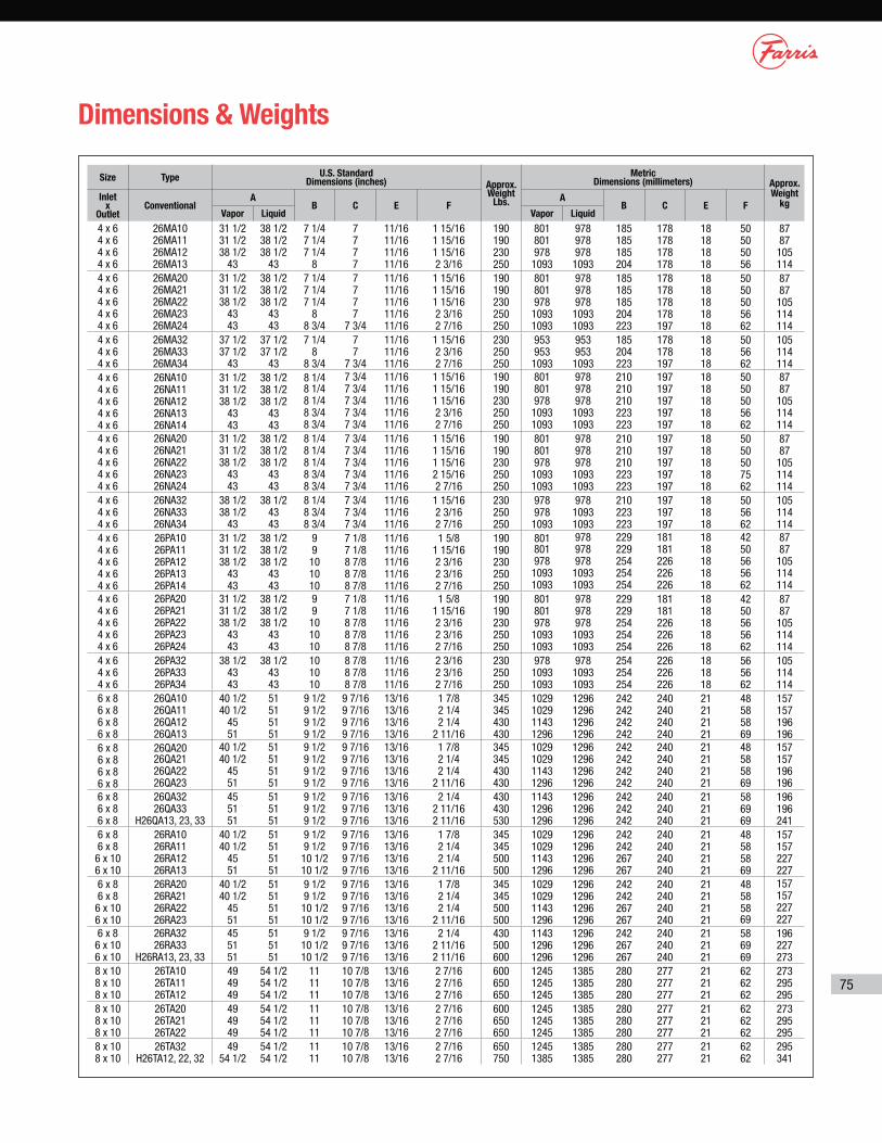
75
Dimensions & Weights
Size Type U.S. Standard Dimensions (inches) Approx.
Weight Lbs.
Metric Dimensions (millimeters) Approx.
Weight kg
Inlet x
OutletConventional
AB C E F
AB C E F
Vapor Liquid Vapor Liquid
4 x 6 4 x 6 4 x 6 4 x 6
26MA10 26MA11 26MA12 26MA13
31 1/2 31 1/2 38 1/2
43
38 1/238 1/238 1/2
43
7 1/4 7 1/4 7 1/4
8
7 7 7 7
11/16 11/16 11/16 11/16
1 15/16 1 15/16 1 15/16 2 3/16
190 190 230 250
801 801 978 1093
978 978 978 1093
185 185 185 204
178 178 178 178
18 18 18 18
50 50 50 56
87 87 105 114
4 x 6 4 x 6 4 x 6 4 x 6 4 x 6
26MA20 26MA21 26MA22 26MA23 26MA24
31 1/2 31 1/2 38 1/2
43 43
38 1/238 1/238 1/2
43 43
7 1/4 7 1/4 7 1/4
8 8 3/4
7 7 7 7
7 3/4
11/16 11/16 11/16 11/16 11/16
1 15/16 1 15/16 1 15/16 2 3/16 2 7/16
190 190 230 250 250
801 801 978 1093 1093
978 978 978 1093 1093
185 185 185 204 223
178 178 178 178 197
18 18 18 18 18
50 50 50 56 62
87 87 105 114 114
4 x 6 4 x 6 4 x 6
26MA32 26MA33 26MA34
37 1/2 37 1/2
43
37 1/2 37 1/2
43
7 1/4 8
8 3/4
7 7
7 3/4
11/16 11/16 11/16
1 15/16 2 3/16 2 7/16
230 250 250
953 953 1093
953 953 1093
185 204 223
178 178 197
18 18 18
50 56 62
105 114 114
4 x 6 4 x 6 4 x 6 4 x 6 4 x 6
26NA10 26NA11 26NA12 26NA13 26NA14
31 1/2 31 1/2 38 1/2
43 43
38 1/238 1/238 1/2
43 43
8 1/4 8 1/4 8 1/4 8 3/4 8 3/4
7 3/4 7 3/4 7 3/4 7 3/4 7 3/4
11/16 11/16 11/16 11/16 11/16
1 15/16 1 15/16 1 15/16 2 3/16 2 7/16
190 190 230 250 250
801 801 978 1093 1093
978 978 978 1093 1093
210 210 210 223 223
197 197 197 197 197
18 18 18 18 18
50 50 50 56 62
87 87 105 114 114
4 x 6 4 x 6 4 x 6 4 x 6 4 x 6
26NA20 26NA21 26NA22 26NA23 26NA24
31 1/2 31 1/2 38 1/2
43 43
38 1/238 1/238 1/2
43 43
8 1/4 8 1/4 8 1/4 8 3/4 8 3/4
7 3/4 7 3/4 7 3/4 7 3/4 7 3/4
11/16 11/16 11/16 11/16 11/16
1 15/16 1 15/16 1 15/16 2 15/16 2 7/16
190 190 230 250 250
801 801 978 1093 1093
978 978 978 1093 1093
210 210 210 223 223
197 197 197 197 197
18 18 18 18 18
50 50 50 75 62
87 87 105 114 114
4 x 6 4 x 6 4 x 6
26NA32 26NA33 26NA34
38 1/238 1/2
43
38 1/24343
8 1/4 8 3/4 8 3/4
7 3/4 7 3/4 7 3/4
11/16 11/16 11/16
1 15/16 2 3/16 2 7/16
230 250 250
978 978 1093
978 1093 1093
210 223 223
197 197 197
18 18 18
50 56 62
105 114 114
4 x 6 4 x 6 4 x 6 4 x 6 4 x 6
26PA10 26PA11 26PA12 26PA13 26PA14
31 1/2 31 1/2 38 1/2
43 43
38 1/238 1/238 1/2
43 43
9 9 10 10 10
7 1/8 7 1/8 8 7/8 8 7/8 8 7/8
11/16 11/16 11/16 11/16 11/16
1 5/8 1 15/16 2 3/16 2 3/16 2 7/16
190 190 230 250 250
801 801 978 1093 1093
978 978 978 1093 1093
229 229 254 254 254
181 181 226 226 226
18 18 18 18 18
42 50 56 56 62
87 87 105 114 114
4 x 6 4 x 6 4 x 6 4 x 6 4 x 6
26PA20 26PA21 26PA22 26PA23 26PA24
31 1/2 31 1/2 38 1/2
43 43
38 1/238 1/238 1/2
43 43
9 9 10 10 10
7 1/8 7 1/8 8 7/8 8 7/8 8 7/8
11/16 11/16 11/16 11/16 11/16
1 5/8 1 15/16 2 3/16 2 3/16 2 7/16
190 190 230 250 250
801 801 978 1093 1093
978 978 978 1093 1093
229 229 254 254 254
181 181 226 226 226
18 18 18 18 18
42 50 56 56 62
87 87 105 114 114
4 x 6 4 x 6 4 x 6
26PA32 26PA33 26PA34
38 1/243 43
38 1/243 43
10 10 10
8 7/8 8 7/8 8 7/8
11/16 11/16 11/16
2 3/16 2 3/16 2 7/16
230 250 250
978 1093 1093
978 1093 1093
254 254 254
226 226 226
18 18 18
56 56 62
105 114 114
6 x 8 6 x 8 6 x 8 6 x 8
26QA10 26QA11 26QA12 26QA13
40 1/2 40 1/2
45 51
51 51 51 51
9 1/2 9 1/2 9 1/2 9 1/2
9 7/16 9 7/16 9 7/16 9 7/16
13/16 13/16 13/16 13/16
1 7/8 2 1/4 2 1/4
2 11/16
345 345 430 430
1029 1029 1143 1296
1296 1296 1296 1296
242 242 242 242
240 240 240 240
21 21 21 21
48 58 58 69
157 157 196 196
6 x 8 6 x 8 6 x 8 6 x 8
26QA20 26QA21 26QA22 26QA23
40 1/2 40 1/2
45 51
51 51 51 51
9 1/2 9 1/2 9 1/2 9 1/2
9 7/16 9 7/16 9 7/16 9 7/16
13/16 13/16 13/16 13/16
1 7/8 2 1/4 2 1/4
2 11/16
345 345 430 430
1029 1029 1143 1296
1296 1296 1296 1296
242 242 242 242
240 240 240 240
21 21 21 21
48 58 58 69
157 157 196 196
6 x 8 6 x 8 6 x 8
26QA32 26QA33
H26QA13, 23, 33
45 51 51
51 51 51
9 1/2 9 1/2 9 1/2
9 7/16 9 7/16 9 7/16
13/16 13/16 13/16
2 1/4 2 11/16 2 11/16
430 430 530
1143 1296 1296
1296 1296 1296
242 242 242
240 240 240
21 21 21
58 69 69
196 196 241
6 x 8 6 x 8 6 x 10 6 x 10
26RA10 26RA11 26RA12 26RA13
40 1/2 40 1/2
45 51
51 51 51 51
9 1/2 9 1/2 10 1/2 10 1/2
9 7/16 9 7/16 9 7/16 9 7/16
13/16 13/16 13/16 13/16
1 7/8 2 1/4 2 1/4
2 11/16
345 345 500 500
1029 1029 1143 1296
1296 1296 1296 1296
242 242 267 267
240 240 240 240
21 21 21 21
48 58 58 69
157 157 227 227
6 x 8 6 x 8 6 x 10 6 x 10
26RA20 26RA21 26RA22 26RA23
40 1/2 40 1/2
45 51
51 51 51 51
9 1/2 9 1/2 10 1/2 10 1/2
9 7/16 9 7/16 9 7/16 9 7/16
13/16 13/16 13/16 13/16
1 7/8 2 1/4 2 1/4
2 11/16
345 345 500 500
1029 1029 1143 1296
1296 1296 1296 1296
242 242 267 267
240 240 240 240
21 21 21 21
48 58 58 69
157 157 227 227
6 x 8 6 x 10 6 x 10
26RA32 26RA33
H26RA13, 23, 33
45 51 51
51 51 51
9 1/2 10 1/2 10 1/2
9 7/16 9 7/16 9 7/16
13/16 13/16 13/16
2 1/4 2 11/16 2 11/16
430 500 600
1143 1296 1296
1296 1296 1296
242 267 267
240 240 240
21 21 21
58 69 69
196 227 273
8 x 10 8 x 10 8 x 10
26TA10 26TA11 26TA12
49 49 49
54 1/2 54 1/2 54 1/2
11 11 11
10 7/8 10 7/8 10 7/8
13/16 13/16 13/16
2 7/16 2 7/16 2 7/16
600 650 650
1245 1245 1245
1385 1385 1385
280 280 280
277 277 277
21 21 21
62 62 62
273 295 295
8 x 10 8 x 10 8 x 10
26TA20 26TA21 26TA22
49 49 49
54 1/2 54 1/2 54 1/2
11 11 11
10 7/8 10 7/8 10 7/8
13/16 13/16 13/16
2 7/16 2 7/16 2 7/16
600 650 650
1245 1245 1245
1385 1385 1385
280 280 280
277 277 277
21 21 21
62 62 62
273 295 295
8 x 10 8 x 10
26TA32 H26TA12, 22, 32
49 54 1/2
54 1/2 54 1/2
11 11
10 7/8 10 7/8
13/16 13/16
2 7/16 2 7/16
650 750
1245 1385
1385 1385
280 280
277 277
21 21
62 62
295 341

79
Valve Pressure Limits
Austenitic Stainless Steel: ASME SA-351 Grade CF8M1–316 St. St
Orifice Letter
Valve Size ANSI Flange ClassMaximum Pressure (psig)
Temperature Range Back Pressure Limit 6
Inlet by Orifice by
OutletInlet Outlet
-450°F to -76°F
-75°F to 100°F
450°F 800°F 1000°FConventional
TypeBalanSeal
Type
D
1D2 1D22
1D2 1D2
1-1/2 D2 1-1/2 D2 1-1/2 D3
150 300 300 600 900 1500 2500
150 150 150 150 300 300 300
275 275 720 1440 2160 3600 4000
275 275 720 1440 2160 3600 6000
180 275 495 990 1485 2480 4130
80 275 420 845 1265 2110 3520
20 275 350 700 1050 1750 2915
275 275 275 275 600 600 720
230 230 230 230 500 500 500
E
1E2 1E22
1E2 1E2
1-1/2 E2 1-1/2 E2 1-1/2 E3
150 300 300 600 900 1500 2500
150 150 150 150 300 300 300
275 275 720 1440 2160 3600 4000
275 275 720 1440 2160 3600 6000
180 275 495 975 1485 2480 4130
80 275 420 845 1265 2110 3520
20 275 350 700 1050 1750 2915
275 275 275 275 600 600 720
230 230 230 230 500 500 500
F
1-1/2 F2 1-1/2 F22
1-1/2 F2 1-1/2 F2 1-1/2 F3 1-1/2 F3 1-1/2 F3
150 300 300 600 900 1500 2500
150 150 150 150 300 300 300
275 275 720 1440 2160 2200 3400
275 275 720 1440 2160 3600 5000
180 275 495 975 1485 2480 4130
80 275 420 845 1265 2110 3520
20 275 350 700 1050 1750 2915
275 275 275 275 600 600 720
230 230 230 230 500 500 500
G
1-1/2 G3 1-1/2 G32
1-1/2 G3 1-1/2 G3 1-1/2 G3
2G3 2G3
150 300 300 600 900 1500 2500
150 150 150 150 300 300 300
275 275 720 1440 2160 2450 2600
275 275 720 1440 2160 3600 3600
180 275 495 975 1485 2480 3600
80 275 420 845 1265 2110 3520
20 275 350 700 1050 1750 2915
275 275 275 275 600 600 720
230 230 230 230 470 470 470
H
1-1/2 H3 1-1/2 H32
2H3 2H3 2H3 2H3
150 300 300 600 900 1500
150 150 150 150 150 300
275 275 720 1440 1485 1600
275 275 720 1440 2160 2750
180 275 495 975 1485 2480
80 275 420 845 1265 2110
20 275 350 700 1050 1750
275 275 275 275 275 600
230 230 230 230 230 415
J
2J3 2J32
3J4 3J4 3J4 3J4
150 300 300 600 900 1500
150 150 150 150 150 300
275 275 500 625 800 800
275 275 720 1440 2160 2700
180 275 495 975 1485 2480
80 275 420 845 1265 2110
20 275 350 700 1050 1750
275 275 275 275 275 600
230 230 230 230 230 230
General Notes:
1. Material limited to 1500°F.
2. Pressure less than rating for 300# class flange to designate maximum pressure limit when used on Farris 300# lightweight design valves.
3. High pressure version
4. Material commonly designated as 316 Stainless Steel.
5. Pressures shown represent values shown in API Standard 526 and/or ASME B16.34.
6. Back pressure limits based on temperature of 100°F.
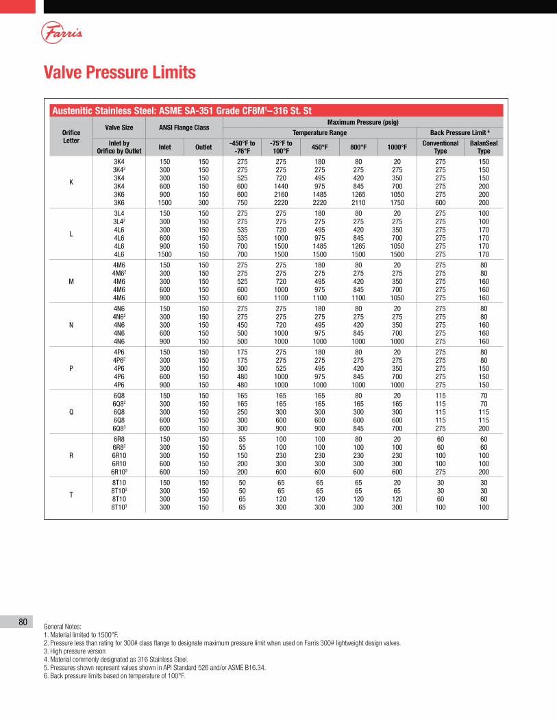
80
Valve Pressure Limits
Austenitic Stainless Steel: ASME SA-351 Grade CF8M1–316 St. St
Orifice Letter
Valve Size ANSI Flange ClassMaximum Pressure (psig)
Temperature Range Back Pressure Limit 6
Inlet by Orifice by Outlet
Inlet Outlet-450°F to
-76°F-75°F to 100°F
450°F 800°F 1000°FConventional
TypeBalanSeal
Type
K
3K4 3K42
3K4 3K4 3K6 3K6
150 300 300 600 900 1500
150 150 150 150 150 300
275 275 525 600 600 750
275 275 720 1440 2160 2220
180 275 495 975 1485 2220
80 275 420 845 1265 2110
20 275 350 700 1050 1750
275 275 275 275 275 600
150 150 150 200 200 200
L
3L4 3L42
4L6 4L6 4L6 4L6
150 300 300 600 900 1500
150 150 150 150 150 150
275 275 535 535 700 700
275 275 720 1000 1500 1500
180 275 495 975 1485 1500
80 275 420 845 1265 1500
20 275 350 700 1050 1500
275 275 275 275 275 275
100 100 170 170 170 170
M
4M6 4M62
4M6 4M6 4M6
150 300 300 600 900
150 150 150 150 150
275 275 525 600 600
275 275 720 1000 1100
180 275 495 975 1100
80 275 420 845 1100
20 275 350 700 1050
275 275 275 275 275
80 80 160 160 160
N
4N6 4N62
4N6 4N6 4N6
150 300 300 600 900
150 150 150 150 150
275 275 450 500 500
275 275 720 1000 1000
180 275 495 975 1000
80 275 420 845 1000
20 275 350 700 1000
275 275 275 275 275
80 80 160 160 160
P
4P6 4P62
4P6 4P6 4P6
150 300 300 600 900
150 150 150 150 150
175 175 300 480 480
275 275 525 1000 1000
180 275 495 975 1000
80 275 420 845 1000
20 275 350 700 1000
275 275 275 275 275
80 80 150 150 150
Q
6Q8 6Q82
6Q8 6Q8 6Q83
150 300 300 600 600
150 150 150 150 150
165 165 250 300 300
165 165 300 600 900
165 165 300 600 900
80 165 300 600 845
20 165 300 600 700
115 115 115 115 275
70 70 115 115 200
R
6R8 6R82
6R10 6R10 6R103
150 300 300 600 600
150 150 150 150 150
55 55 150 200 200
100 100 230 300 600
100 100 230 300 600
80 100 230 300 600
20 100 230 300 600
60 60 100 100 275
60 60 100 100 200
T
8T10 8T102
8T10 8T103
150 300 300 300
150 150 150 150
50 50 65 65
65 65 120 300
65 65 120 300
65 65 120 300
20 65 120 300
30 30 60 100
30 30 60 100
General Notes:
1. Material limited to 1500°F.
2. Pressure less than rating for 300# class flange to designate maximum pressure limit when used on Farris 300# lightweight design valves.
3. High pressure version
4. Material commonly designated as 316 Stainless Steel.
5. Pressures shown represent values shown in API Standard 526 and/or ASME B16.34.
6. Back pressure limits based on temperature of 100°F.
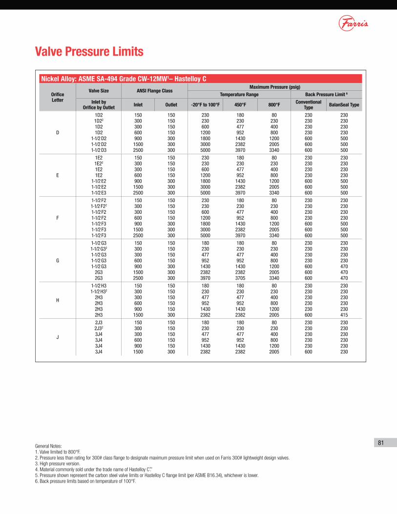
81
Valve Pressure Limits
Nickel Alloy: ASME SA-494 Grade CW-12MW1– Hastelloy C
Orifice Letter
Valve Size ANSI Flange ClassMaximum Pressure (psig)
Temperature Range Back Pressure Limit 6
Inlet by Orifice by Outlet
Inlet Outlet -20°F to 100°F 450°F 800°FConventional
TypeBalanSeal Type
D
1D2 1D22
1D2 1D2
1-1/2 D2 1-1/2 D2 1-1/2 D3
150 300 300 600 900 1500 2500
150 150 150 150 300 300 300
230 230 600 1200 1800 3000 5000
180 230 477 952 1430 2382 3970
80 230 400 800 1200 2005 3340
230 230 230 230 600 600 600
230 230 230 230 500 500 500
E
1E2 1E22
1E2 1E2
1-1/2 E2 1-1/2 E2 1-1/2 E3
150 300 300 600 900 1500 2500
150 150 150 150 300 300 300
230 230 600 1200 1800 3000 5000
180 230 477 952 1430 2382 3970
80 230 400 800 1200 2005 3340
230 230 230 230 600 600 600
230 230 230 230 500 500 500
F
1-1/2 F2 1-1/2 F22
1-1/2 F2 1-1/2 F2 1-1/2 F3 1-1/2 F3 1-1/2 F3
150 300 300 600 900 1500 2500
150 150 150 150 300 300 300
230 230 600 1200 1800 3000 5000
180 230 477 952 1430 2382 3970
80 230 400 800 1200 2005 3340
230 230 230 230 600 600 600
230 230 230 230 500 500 500
G
1-1/2 G3 1-1/2 G32
1-1/2 G3 1-1/2 G3 1-1/2 G3
2G3 2G3
150 300 300 600 900 1500 2500
150 150 150 150 300 300 300
180 230 477 952 1430 2382 3970
180 230 477 952 1430 2382 3705
80 230 400 800 1200 2005 3340
230 230 230 230 600 600 600
230 230 230 230 470 470 470
H
1-1/2 H3 1-1/2 H32
2H3 2H3 2H3 2H3
150 300 300 600 900 1500
150 150 150 150 150 300
180 230 477 952 1430 2382
180 230 477 952 1430 2382
80 230 400 800 1200 2005
230 230 230 230 230 600
230 230 230 230 230 415
J
2J3 2J32
3J4 3J4 3J4 3J4
150 300 300 600 900 1500
150 150 150 150 150 300
180 230 477 952 1430 2382
180 230 477 952 1430 2382
80 230 400 800 1200 2005
230 230 230 230 230 600
230 230 230 230 230 230
General Notes:
1. Valve limited to 800°F.
2. Pressure less than rating for 300# class flange to designate maximum pressure limit when used on Farris 300# lightweight design valves.
3. High pressure version.
4. Material commonly sold under the trade name of Hastelloy C™.
5. Pressure shown represent the carbon steel valve limits or Hastelloy C flange limit (per ASME B16.34), whichever is lower.
6. Back pressure limits based on temperature of 100°F.
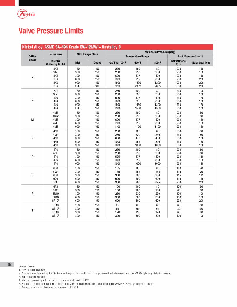
82
Valve Pressure Limits
Nickel Alloy: ASME SA-494 Grade CW-12MW1– Hastelloy C
Orifice Letter
Valve Size ANSI Flange ClassMaximum Pressure (psig)
Temperature Range Back Pressure Limit 6
Inlet by Orifice by Outlet
Inlet Outlet -20°F to 100°F 450°F 800°FConventional
TypeBalanSeal Type
K
3K4 3K42
3K4 3K4 3K6 3K6
150 300 300 600 900 1500
150 150 150 150 150 300
230 230 600 1200 1800 2220
180 230 477 952 1430 2382
80 230 400 800 1200 2005
230 230 230 230 230 600
150 150 150 200 200 200
L
3L4 3L42
4L6 4L6 4L6 4L6
150 300 300 600 900 1500
150 150 150 150 150 150
230 230 600 1000 1500 1500
180 230 477 952 1430 1500
80 230 400 800 1200 1500
230 230 230 230 230 230
100 100 170 170 170 170
M
4M6 4M62
4M6 4M6 4M6
150 300 300 600 900
150 150 150 150 150
230 230 600 1100 1100
180 230 477 952 1100
80 230 400 800 1100
230 230 230 230 230
80 80 160 160 160
N
4N6 4N62
4N6 4N6 4N6
150 300 300 600 900
150 150 150 150 150
230 230 600 1000 1000
180 230 477 952 1000
80 230 400 800 1000
230 230 230 230 230
80 80 160 160 160
P
4P6 4P62
4P6 4P6 4P6
150 300 300 600 900
150 150 150 150 150
230 230 525 1000 1000
180 230 477 952 1000
80 230 400 800 1000
230 230 230 230 230
80 80 150 150 150
Q
6Q8 6Q82
6Q8 6Q8 6Q83
150 300 300 600 600
150 150 150 150 150
165 165 300 600 900
165 165 300 600 900
80 165 300 600 825
140 115 115 115 230
70 70 115 115 200
R
6R8 6R82
6R10 6R10 6R103
150 300 300 600 600
150 150 150 150 150
100 100 230 300 600
100 100 230 300 600
80 100 230 300 600
100 60 100 100 230
60 60 100 100 200
T
8T10 8T102
8T10 8T103
150 300 300 300
150 150 150 150
65 65 120 300
65 65 120 300
65 65 120 300
65 30 60 100
30 30 60 100
General Notes:
1. Valve limited to 800°F.
2. Pressure less than rating for 300# class flange to designate maximum pressure limit when used on Farris 300# lightweight design valves.
3. High pressure version.
4. Material commonly sold under the trade name of Hastelloy C™.
5. Pressures shown represent the carbon steel valve limits or Hastelloy C flange limit (per ASME B16.34), whichever is lower.
6. Back pressure limits based on temperature of 100°F.
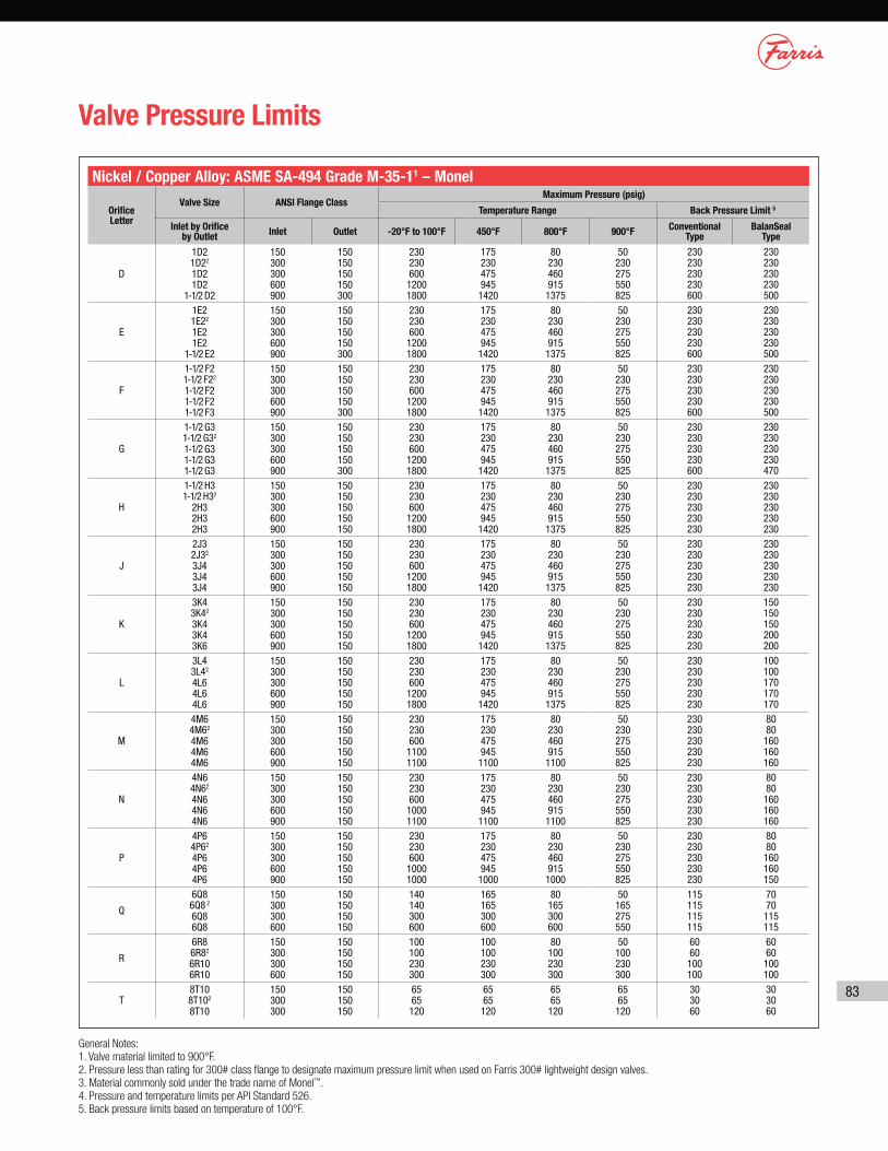
83
Valve Pressure Limits
Nickel / Copper Alloy: ASME SA-494 Grade M-35-11 – Monel
Orifice Letter
Valve Size ANSI Flange ClassMaximum Pressure (psig)
Temperature Range Back Pressure Limit 5
Inlet by Orifice by Outlet
Inlet Outlet -20°F to 100°F 450°F 800°F 900°FConventional
TypeBalanSeal
Type
D
1D2 1D22
1D2 1D2
1-1/2 D2
150 300 300 600 900
150 150 150 150 300
230 230 600 1200 1800
175 230 475 945 1420
80 230 460 915 1375
50 230 275 550 825
230 230 230 230 600
230 230 230 230 500
E
1E2 1E22
1E2 1E2
1-1/2 E2
150 300 300 600 900
150 150 150 150 300
230 230 600 1200 1800
175 230 475 945 1420
80 230 460 915 1375
50 230 275 550 825
230 230 230 230 600
230 230 230 230 500
F
1-1/2 F2 1-1/2 F22
1-1/2 F2 1-1/2 F2 1-1/2 F3
150 300 300 600 900
150 150 150 150 300
230 230 600 1200 1800
175 230 475 945 1420
80 230 460 915 1375
50 230 275 550 825
230 230 230 230 600
230 230 230 230 500
G
1-1/2 G3 1-1/2 G32
1-1/2 G3 1-1/2 G3 1-1/2 G3
150 300 300 600 900
150 150 150 150 300
230 230 600 1200 1800
175 230 475 945 1420
80 230 460 915 1375
50 230 275 550 825
230 230 230 230 600
230 230 230 230 470
H
1-1/2 H3 1-1/2 H32
2H3 2H3 2H3
150 300 300 600 900
150 150 150 150 150
230 230 600 1200 1800
175 230 475 945 1420
80 230 460 915 1375
50 230 275 550 825
230 230 230 230 230
230 230 230 230 230
J
2J3 2J32
3J4 3J4 3J4
150 300 300 600 900
150 150 150 150 150
230 230 600 1200 1800
175 230 475 945 1420
80 230 460 915 1375
50 230 275 550 825
230 230 230 230 230
230 230 230 230 230
K
3K4 3K42
3K4 3K4 3K6
150 300 300 600 900
150 150 150 150 150
230 230 600 1200 1800
175 230 475 945 1420
80 230 460 915 1375
50 230 275 550 825
230 230 230 230 230
150 150 150 200 200
L
3L4 3L42
4L6 4L6 4L6
150 300 300 600 900
150 150 150 150 150
230 230 600 1200 1800
175 230 475 945 1420
80 230 460 915 1375
50 230 275 550 825
230 230 230 230 230
100 100 170 170 170
M
4M6 4M62
4M6 4M6 4M6
150 300 300 600 900
150 150 150 150 150
230 230 600 1100 1100
175 230 475 945 1100
80 230 460 915 1100
50 230 275 550 825
230 230 230 230 230
80 80 160 160 160
N
4N6 4N62
4N6 4N6 4N6
150 300 300 600 900
150 150 150 150 150
230 230 600 1000 1100
175 230 475 945 1100
80 230 460 915 1100
50 230 275 550 825
230 230 230 230 230
80 80 160 160 160
P
4P6 4P62
4P6 4P6 4P6
150 300 300 600 900
150 150 150 150 150
230 230 600 1000 1000
175 230 475 945 1000
80 230 460 915 1000
50 230 275 550 825
230 230 230 230 230
80 80 160 160 150
Q
6Q8 6Q8 2
6Q8 6Q8
150 300 300 600
150 150 150 150
140 140 300 600
165 165 300 600
80 165 300 600
50 165 275 550
115 115 115 115
70 70 115 115
R
6R8 6R82
6R10 6R10
150 300 300 600
150 150 150 150
100 100 230 300
100 100 230 300
80 100 230 300
50 100 230 300
60 60 100 100
60 60 100 100
T8T10 8T102
8T10
150 300 300
150 150 150
65 65 120
65 65 120
65 65 120
65 65 120
30 30 60
30 30 60
General Notes:
1. Valve material limited to 900°F.
2. Pressure less than rating for 300# class flange to designate maximum pressure limit when used on Farris 300# lightweight design valves.
3. Material commonly sold under the trade name of Monel™.
4. Pressure and temperature limits per API Standard 526.
5. Back pressure limits based on temperature of 100°F.
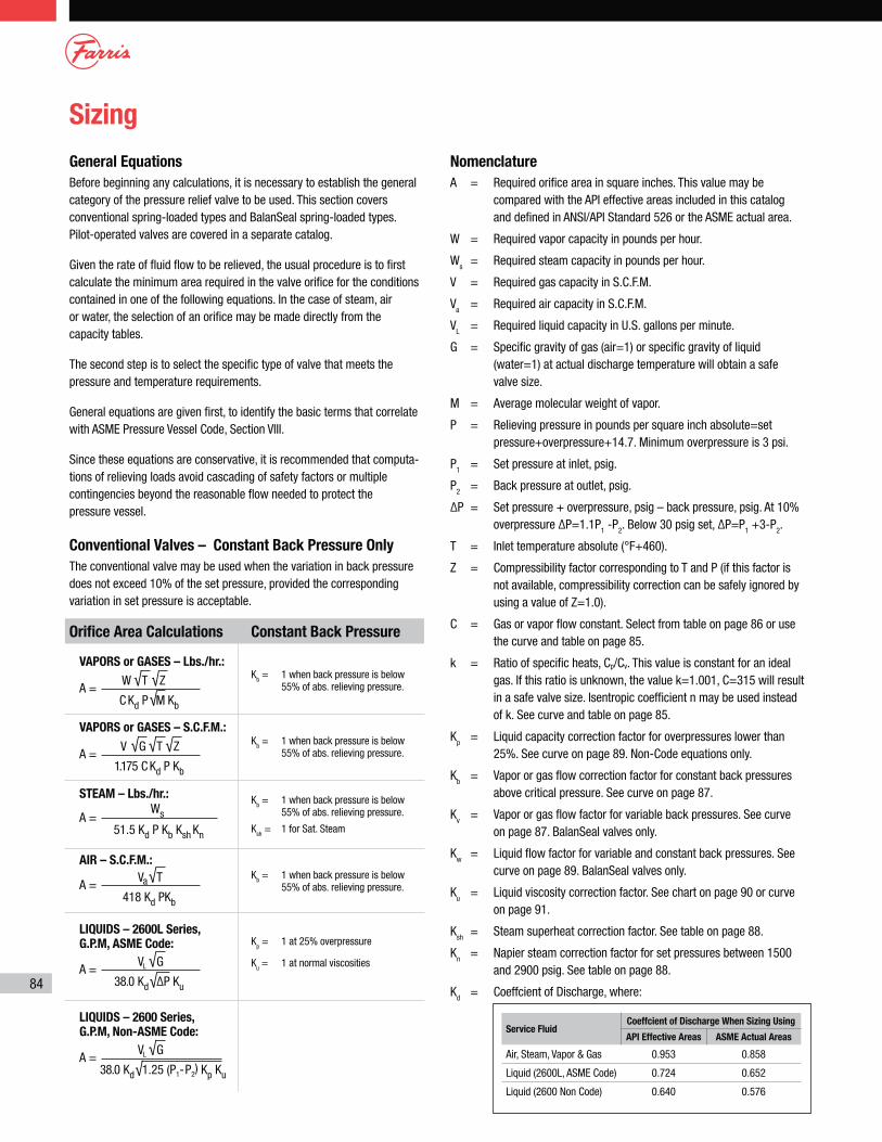
84
Sizing
General Equations
Before beginning any calculations, it is necessary to establish the general category of the pressure relief valve to be used. This section covers conventional spring-loaded types and BalanSeal spring-loaded types. Pilot-operated valves are covered in a separate catalog.
Given the rate of fluid flow to be relieved, the usual procedure is to first calculate the minimum area required in the valve orifice for the conditions contained in one of the following equations. In the case of steam, air or water, the selection of an orifice may be made directly from the capa city tables.
The second step is to select the specific type of valve that meets the pressure and temperature requirements.
General equations are given first, to identify the basic terms that correlate with ASME Pressure Vessel Code, Section VIII.
Since these equations are conservative, it is recommended that computa-tions of relieving loads avoid cascading of safety factors or multiple contingencies beyond the reasonable flow needed to protect the pressure vessel.
Conventional Valves – Constant Back Pressure Only
The conventional valve may be used when the variation in back pressure does not exceed 10% of the set pressure, provided the corresponding variation in set pressure is acceptable.
Nomenclature
A = Required orifice area in square inches. This value may be compared with the API effective areas included in this catalog and defined in ANSI/API Standard 526 or the ASME actual area.
W = Required vapor capacity in pounds per hour.
Ws = Required steam capacity in pounds per hour.
V = Required gas capacity in S.C.F.M.
Va = Required air capacity in S.C.F.M.
VL = Required liquid capacity in U.S. gallons per minute.
G = Specific gravity of gas (air=1) or specific gravity of liquid (water=1) at actual discharge temperature will obtain a safe valve size.
M = Average molecular weight of vapor.
P = Relieving pressure in pounds per square inch absolute=set pressure+overpressure+14.7. Minimum overpressure is 3 psi.
P1 = Set pressure at inlet, psig.
P2 = Back pressure at outlet, psig.
ΔP = Set pressure + overpressure, psig – back pressure, psig. At 10% overpressure ΔP=1.1P1 -P2. Below 30 psig set, ΔP=P1 +3-P2.
T = Inlet temperature absolute (°F+460).
Z = Compressibility factor corresponding to T and P (if this factor is not available, compressibility correction can be safely ignored by using a value of Z=1.0).
C = Gas or vapor flow constant. Select from table on page 86 or use the curve and table on page 85.
k = Ratio of specific heats, Cp/Cv. This value is constant for an ideal gas. If this ratio is unknown, the value k=1.001, C=315 will result in a safe valve size. Isentropic coefficient n may be used instead of k. See curve and table on page 85.
Kp = Liquid capacity correction factor for overpressures lower than
25%. See curve on page 89. Non-Code equations only.
Kb = Vapor or gas flow correction factor for constant back pressures above critical pressure. See curve on page 87.
Kv = Vapor or gas flow factor for variable back pressures. See curve on page 87. BalanSeal valves only.
Kw = Liquid flow factor for variable and constant back pressures. See curve on page 89. BalanSeal valves only.
Ku = Liquid viscosity correction factor. See chart on page 90 or curve on page 91.
Ksh = Steam superheat correction factor. See table on page 88.
Kn = Napier steam correction factor for set pressures between 1500 and 2900 psig. See table on page 88.
Kd = Coeffcient of Discharge, where:
Service FluidCoeffcient of Discharge When Sizing Using
API Effective Areas ASME Actual Areas
Air, Steam, Vapor & Gas 0.953 0.858
Liquid (2600L, ASME Code) 0.724 0.652
Liquid (2600 Non Code) 0.640 0.576
Kp = 1 at 25% overpressure
Ku = 1 at normal viscosities
Kb = 1 when back pressure is below 55% of abs. relieving pressure.
Kb = 1 when back pressure is below
55% of abs. relieving pressure.
Ksh = 1 for Sat. Steam
Kb = 1 when back pressure is below 55% of abs. relieving pressure.
Constant Back Pressure
Kb = 1 when back pressure is below 55% of abs. relieving pressure.
Orifice Area Calculations
A =√ √
√W T Z
M C Kd P Kb
VAPORS or GASES – Lbs./hr.:
A =√√
VL G
38.0 Kd ΔP Ku
LIQUIDS – 2600L Series,
G.P.M, ASME Code:
A =√Va T
418 Kd PKb
AIR – S.C.F.M.:
A =√
√VL G
38.0 Kd 1.25 (P1-P2) Kp Ku
LIQUIDS – 2600 Series,
G.P.M, Non-ASME Code:
A =√ √ √V G T Z
1.175 C Kd P Kb
VAPORS or GASES – S.C.F.M.:
A =Ws
51.5 Kd P Kb Ksh Kn
STEAM – Lbs./hr.:
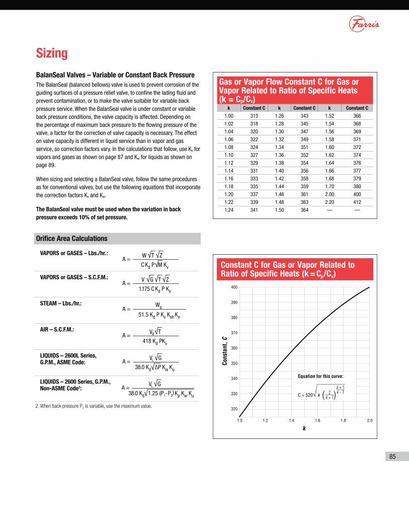
85
Sizing
BalanSeal Valves – Variable or Constant Back Pressure
The BalanSeal (balanced bellows) valve is used to prevent corrosion of the guiding surfaces of a pressure relief valve, to confine the lading fluid and prevent contamination, or to make the valve suitable for variable back pressure service. When the BalanSeal valve is under constant or variable back pressure conditions, the valve capacity is affected. Depending on the percentage of maximum back pressure to the flowing pressure of the valve, a factor for the correction of valve capacity is necessary. The effect on valve capacity is different in liquid service than in vapor and gas service, so correction factors vary. In the calculations that follow, use Kv for vapors and gases as shown on page 87 and Kw for liquids as shown on page 89.
When sizing and selecting a BalanSeal valve, follow the same procedures as for conventional valves, but use the following equations that incorporate the correction factors Kv and Kw.
The BalanSeal valve must be used when the variation in back
pressure exceeds 10% of set pressure.
Gas or Vapor Flow Constant C for Gas or Vapor Related to Ratio of Specific Heats (k = Cp/Cv)
k Constant C k Constant C k Constant C
1.00 315 1.26 343 1.52 366
1.02 318 1.28 345 1.54 368
1.04 320 1.30 347 1.56 369
1.06 322 1.32 349 1.58 371
1.08 324 1.34 351 1.60 372
1.10 327 1.36 352 1.62 374
1.12 329 1.38 354 1.64 376
1.14 331 1.40 356 1.66 377
1.16 333 1.42 358 1.68 379
1.18 335 1.44 359 1.70 380
1.20 337 1.46 361 2.00 400
1.22 339 1.48 363 2.20 412
1.24 341 1.50 364 — —
2. When back pressure P2 is variable, use the maximum value.
Orifice Area Calculations
A =√ √
√W T Z
M C Kd P Kv
VAPORS or GASES – Lbs./hr.:
A =√
√VL G
38.0 Kd ΔP Kw Ku
LIQUIDS – 2600L Series,
G.P.M., ASME Code:
A =√Va T
418 Kd PKv
AIR – S.C.F.M.:
A =√
√VL G
38.0 Kd 1.25 (P1-P2) Kp Kw Ku
LIQUIDS – 2600 Series, G.P.M.,
Non-ASME Code2:
A =√ √ √V G T Z
1.175 C Kd P Kv
VAPORS or GASES – S.C.F.M.:
A =Ws
51.5 Kd P Kv Ksh Kn
STEAM – Lbs./hr.:
Constant C for Gas or Vapor Related to Ratio of Specific Heats (k = Cp/Cv)
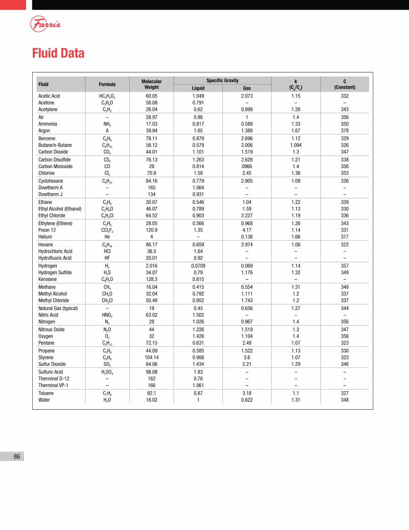
86
Fluid Data
Fluid FormulaMolecular
Weight
Specific Gravity k (C
p/C
v)
C (Constant)Liquid Gas
Acetic Acid Acetone Acetylene
HC2H3O2
C3H6OC2H2
60.05 58.08 26.04
1.049 0.791 0.62
2.073 –
0.899
1.15 –
1.26
332 –
343
Air Ammonia Argon
– NH3
A
28.97 17.03 39.94
0.86 0.817 1.65
1 0.588 1.388
1.4 1.33 1.67
356 350 378
Benzene Butane/n-Butane Carbon Dioxide
C6H6
C4H10
CO2
78.11 58.12 44.01
0.879 0.579 1.101
2.696 2.006 1.519
1.12 1.094 1.3
329 326 347
Carbon Disulfide Carbon Monoxide Chlorine
CS2
CO CI2
76.13 28
70.9
1.263 0.814 1.58
2.628 0966 2.45
1.21 1.4 1.36
338 356 353
Cyclohexane Dowtherm A Dowtherm J
C6H12
– –
84.16 165 134
0.779 1.064 0.931
2.905 – –
1.09 – –
326 – –
Ethane Ethyl Alcohol (Ethanol) Ethyl Chloride
C2H6
C2H6OC2H5CI
30.07 46.07 64.52
0.546 0.789 0.903
1.04 1.59 2.227
1.22 1.13 1.19
339 330 336
Ethylene (Ethene) Freon 12 Helium
C2H4
CCI2F2
He
28.05 120.9
4
0.566 1.35
–
0.968 4.17 0.138
1.26 1.14 1.66
343 331 377
Hexane Hydrochloric Acid Hydrofluoric Acid
C6H14
HCI HF
86.17 36.5 20.01
0.659 1.64 0.92
2.974 – –
1.06 – –
322 – –
Hydrogen Hydrogen Sulfide Kerosene
H2
H2SC9H2O
2.016 34.07 128.3
0.0709 0.79 0.815
0.069 1.176
–
1.14 1.32
–
357 349 –
Methane Methyl Alcohol Methyl Chloride
CH4
CH4OCH3CI
16.04 32.04 50.49
0.415 0.792 0.952
0.554 1.111 1.743
1.31 1.2 1.2
348 337 337
Natural Gas (typical) Nitric Acid Nitrogen
– HNO3
N2
19 63.02
28
0.45 1.502 1.026
0.656 –
0.967
1.27 –
1.4
344 –
356
Nitrous Oxide Oxygen Pentane
N2OO2
C5H12
44 32
72.15
1.226 1.426 0.631
1.519 1.104 2.49
1.3 1.4 1.07
347 356 323
Propane Styrene Sulfur Dioxide
C3H8
C8H8
SO2
44.09 104.14 64.06
0.585 0.906 1.434
1.522 3.6 2.21
1.13 1.07 1.29
330 323 346
Sulfuric Acid Therminol D-12 Therminol VP-1
H2SO4
– –
98.08 162 166
1.83 0.76 1.061
– – –
– – –
– – –
Toluene Water
C7H8
H2O92.1 18.02
0.87 1
3.18 0.622
1.1 1.31
327 348

Distributed by | Distribuido por :
TM
Life Flows on ™
WWW.ANYTHINGFLOWS.COM
Flow Control , our passion ®
SCAN ME