high pressure hydrogen pressure relief devices ... pressure hydrogen pressure relief devices: ......
TRANSCRIPT

High Pressure Hydrogen Pressure Relief Devices: Accelerated Life Testing and Application Best Practices R. Burgess, M. Post, W. Buttner, and C. RivkinNational Renewable Energy Laboratory
NREL is a national laboratory of the U.S. Department of Energy Office of Energy Efficiency & Renewable Energy Operated by the Alliance for Sustainable Energy, LLC This report is available at no cost from the National Renewable Energy Laboratory (NREL) at www.nrel.gov/publications.
Technical Report NREL/TP-5400-67381 November 2017
Contract No. DE-AC36-08GO28308

National Renewable Energy Laboratory 15013 Denver West Parkway Golden, CO 80401 303-275-3000 • www.nrel.gov
High Pressure Hydrogen Pressure Relief Devices: Accelerated Life Testing and Application Best Practices R. Burgess, M. Post, W. Buttner, andC. RivkinNational Renewable Energy Laboratory
Prepared under Task No. HT12.7510
NREL is a national laboratory of the U.S. Department of Energy Office of Energy Efficiency & Renewable Energy Operated by the Alliance for Sustainable Energy, LLC This report is available at no cost from the National Renewable Energy Laboratory (NREL) at www.nrel.gov/publications.
Technical Report NREL/TP-5400-67381 November 2017
Contract No. DE-AC36-08GO28308

NOTICE
This report was prepared as an account of work sponsored by an agency of the United States government. Neither the United States government nor any agency thereof, nor any of their employees, makes any warranty, express or implied, or assumes any legal liability or responsibility for the accuracy, completeness, or usefulness of any information, apparatus, product, or process disclosed, or represents that its use would not infringe privately owned rights. Reference herein to any specific commercial product, process, or service by trade name, trademark, manufacturer, or otherwise does not necessarily constitute or imply its endorsement, recommendation, or favoring by the United States government or any agency thereof. The views and opinions of authors expressed herein do not necessarily state or reflect those of the United States government or any agency thereof.
This report is available at no cost from the National Renewable Energy Laboratory (NREL) at www.nrel.gov/publications.
Available electronically at SciTech Connect http:/www.osti.gov/scitech
Available for a processing fee to U.S. Department of Energy and its contractors, in paper, from:
U.S. Department of Energy Office of Scientific and Technical Information P.O. Box 62 Oak Ridge, TN 37831-0062 OSTI http://www.osti.gov Phone: 865.576.8401 Fax: 865.576.5728 Email: [email protected]
Available for sale to the public, in paper, from:
U.S. Department of Commerce National Technical Information Service 5301 Shawnee Road Alexandria, VA 22312 NTIS http://www.ntis.gov Phone: 800.553.6847 or 703.605.6000 Fax: 703.605.6900 Email: [email protected]
Cover Photos by Dennis Schroeder: (left to right) NREL 26173, NREL 18302, NREL 19758, NREL 29642, NREL 19795.
NREL prints on paper that contains recycled content.

iii This report is available at no cost from the National Renewable Energy Laboratory at www.nrel.gov/publications.
List of Acronyms ASME American Society of Mechanical Engineers CGA Compressed Gas Association CHMC compressed hydrogen materials compatibility CT Scan computed tomography scan DOE U.S. Department of Energy ESIF Energy Systems Integration Facility NEMA National Electrical Manufacturers Association NREL National Renewable Energy Laboratory PHMSA Pipeline and Hazardous Materials Safety Administration PLC Programmable Logic Controller PRD pressure relief device SDO Standards Development Organization TEM thermoelectric module

iv This report is available at no cost from the National Renewable Energy Laboratory at www.nrel.gov/publications.
Abstract Pressure relief devices (PRDs1) are used to protect high pressure systems from burst failure caused by overpressurization. Codes and standards require the use of PRDs for the safe design of many pressurized systems. These systems require high reliability due to the risks associated with a burst failure. Hydrogen service can increase the risk of PRD failure due to material property degradation caused by hydrogen attack. The National Renewable Energy Laboratory (NREL) has conducted an accelerated life test on a conventional spring loaded PRD. Based on previous failures in the field, the nozzles specific to these PRDs are of particular interest. A nozzle in a PRD is a small part that directs the flow of fluid toward the sealing surface to maintain the open state of the valve once the spring force is overcome. The nozzle in this specific PRD is subjected to the full tensile force of the fluid pressure. These nozzles are made from 440C material, which is a type of hardened steel that is commonly chosen for high pressure applications because of its high strength properties. In a hydrogen environment, however, 440C is considered a worst case material since hydrogen attack results in a loss of almost all ductility and thus 440C is prone to fatigue and material failure. Accordingly, 440C is not recommended for hydrogen service. Conducting an accelerated life test on a PRD with 440C material provides information on necessary and sufficient conditions required to produce crack initiation and failure. The accelerated life test also provides information on other PRD failure modes that are somewhat statistically random in nature.
NREL performed an accelerated life test by thermal cycling two spring loaded PRDs over a temperature range of 30°C peak to peak, which is greater than a typical diurnal cycle. The PRD accelerated life test simulated a high pressure storage system subjected to only moderate pressure fluctuations over time. A 10-year cycle count was selected as an end of life condition. The two spring loaded PRDs, including nozzles made from 440C material, were able to survive the full simulated 10-year cycle life without failure. There was one spurious valve opening failure where a root cause could not be determined. The spurious opening failure was first detected when system pressure exhibited a steady decrease. Further investigation, which included repressurization, showed that the valve was able to reseat. Potential causes for this failure mode are discussed. These test results show that PRD failure modes in hydrogen service do not originate from a single root cause. Understanding of origins for failure prediction is important for component design in hydrogen service. Use of performance-based, component-level tests may not reveal all insufficiencies for design qualification purposes. An understanding of material properties with respect to hydrogen attack is also important for component design in hydrogen service.
1 Terminology used throughout this report is consistent with definitions in Compressed Gas Association standard CGA S-1.1, which defines a PRD as a pressure and/or temperature activated device used to prevent the pressure in a normally charged cylinder from rising above a predetermined maximum, thereby preventing rupture of the cylinder.

v This report is available at no cost from the National Renewable Energy Laboratory at www.nrel.gov/publications.
Table of Contents 1 Introduction ........................................................................................................................................... 1
1.1 DOE/NREL Hydrogen Safety, Codes and Standards Program ..................................................... 1 1.2 PRD Industry Best Practices ......................................................................................................... 2 1.3 PRD Failure Mode Summary ........................................................................................................ 3
1.3.1 Common PRD Failure Modes .......................................................................................... 3 1.3.2 Contributing Factors to PRD Failure................................................................................ 4
1.4 PRD Case Studies in Hydrogen Service ........................................................................................ 5 1.4.1 PRD Failure at Hydrogen Bus Fueling Station ................................................................ 5 1.4.2 Burst Disk Failure on Hydrogen Transport Cylinder ....................................................... 5 1.4.3 PRD Spurious Opening on NREL Hydrogen Storage ...................................................... 6 1.4.4 PRD Failure to Open during Cryogenic Hydrogen System Overpressure ....................... 6 1.4.5 Industrial Survey of PRD Performance ............................................................................ 7
1.5 NREL Approach to Hydrogen Infrastructure ................................................................................ 7 2 Accelerated Life Test ........................................................................................................................... 8
2.1 Test Objective ............................................................................................................................... 8 2.2 Test Plan ........................................................................................................................................ 8
2.2.1 PRD Hardware Selection ................................................................................................. 8 2.2.2 Accelerated Life Test ....................................................................................................... 9
2.3 Apparatus Design .......................................................................................................................... 9 2.3.1 Overview .......................................................................................................................... 9 2.3.2 Enclosure ........................................................................................................................ 10 2.3.3 Heat Transfer System ..................................................................................................... 11 2.3.4 Automation ..................................................................................................................... 12 2.3.5 Pressurized System Components ................................................................................... 12
2.4 Non-Destructive Examination ..................................................................................................... 15 3 Results ................................................................................................................................................. 16
3.1 Temperature Cycling Test ........................................................................................................... 16 3.2 PRD Failure ................................................................................................................................. 17 3.3 Post-Test Inspection .................................................................................................................... 19 3.4 Implications for Component Level Qualification Testing ........................................................... 19
3.4.1 Understanding Material Failure ..................................................................................... 20 3.4.2 Codes and Standards Methods ....................................................................................... 20
3.5 Findings of the NREL PRD Failure Investigation ...................................................................... 20 4 Conclusions and Recommendations ............................................................................................... 22 References ................................................................................................................................................. 24 Bibliography .............................................................................................................................................. 25

vi This report is available at no cost from the National Renewable Energy Laboratory at www.nrel.gov/publications.
List of Figures Figure 1. Scope of NREL activities in hydrogen safety, codes and standards .............................................. 1 Figure 2. Safety controls hierarchy ............................................................................................................... 2 Figure 3. Results from case study on pressure relief device reliability ......................................................... 7 Figure 4. ESIF hydrogen laboratories ........................................................................................................... 8 Figure 5. Aluminum electrical enclosure for use as temperature control chamber ..................................... 10 Figure 6. NEMA 7/9 hazardous location enclosure for protection against flammable gas leak ................. 10 Figure 7. Thermoelectric module schematic ............................................................................................... 12 Figure 8. Pressurized system components (front view) .............................................................................. 13 Figure 9. Pressurized system components (side view) ................................................................................ 14 Figure 10. PRD apparatus installed in high pressure test cell (photo by NREL) ........................................ 14 Figure 11. CT scan of 440C nozzle with indication of crack ...................................................................... 15 Figure 12. Temperature cycle data .............................................................................................................. 16 Figure 13. Spurious pressure drop due to PRD failure ............................................................................... 17 Figure 14. Typical component failure histogram ........................................................................................ 18

1 This report is available at no cost from the National Renewable Energy Laboratory at www.nrel.gov/publications.
1 Introduction Commercialization of hydrogen fuel cell technologies requires system infrastructure that meets end user expectations for safety and reliability. Industrial gas suppliers have a long history of safe and reliable hydrogen usage; however, the fuel cell electric vehicle market is faced with challenges of supplying 70 MPa hydrogen system pressure at public stations, with maximum fueling pressures up to 87.5 MPa. Public usage of systems at these pressures is not common and will require new approaches to safety, codes, and standards. Commercialization of hydrogen fuel cell technologies requires that systems are designed for use by untrained personnel. This contrasts with hydrogen use at industrial plants where operator knowledge of safe-use protocols is common practice. Pressure relief devices (PRDs) are used in public and industrial applications to prevent overpressurization and burst failure. This report provides background on high pressure hydrogen PRD operation and presents results from an accelerated life test project recently completed at the National Renewable Energy Laboratory’s (NREL’s) Energy Systems Integration Facility (ESIF) high pressure test bay. ESIF was established by the U.S. Department of Energy (DOE) as a user facility for emerging energy technologies.
1.1 DOE/NREL Hydrogen Safety, Codes and Standards Program This work was supported by the DOE Fuel Cell Technologies Office, Safety, Codes and Standards sub-program, in the Office of Energy Efficiency and Renewable Energy. The Safety, Codes and Standards sub-program is working to develop and implement practices and procedures that ensure safety in operating, handling, and using hydrogen and hydrogen systems. NREL supports this mission by performing pre-normative research and development in technical topic areas where gaps exist in the understanding of how high pressure hydrogen impacts component and system level behavior. The fishbone diagram in Figure 1 depicts the overall scope of the sub-program at NREL. The work on PRDs fits within the component safety evaluation section.
Figure 1. Scope of NREL activities in hydrogen safety, codes and standards

2 This report is available at no cost from the National Renewable Energy Laboratory at www.nrel.gov/publications.
1.2 PRD Industry Best Practices PRDs are used on pressurized systems to protect against overpressurization and the potential of burst failure. There are several types of PRDs, designed to respond to an overpressure event by venting the process fluid to the atmosphere. PRDs are ubiquitous in this role in pressure safety and have a long history of safe operation. The term PRD is used here as defined by the Compressed Gas Association (CGA) as a general term for a device that relieves pressure. There are many types of pressure relief devices, including spring activated relief valves, pilot operated relief valves, burst disks, temperature activated relief valves, eutectic plugs, and others. Proper application of PRDs requires not only selection of the device that meets the design requirements but also engineering and administrative controls that ensure the PRD will meet the long term reliability needs. PRD manufacturers recommend that maintenance intervals should be determined by the system operator and should be based on consideration of the severity of service and the acceptable level of risk. Maintenance procedures typically include inspection and resetting of the relief pressure as well as replacing soft materials, seats, and wear parts. Recommended service intervals are typically once every year for severe service and every three to five years for routine service.
The hierarchy of controls diagram in Figure 2 depicts generally accepted best practices for mitigating risk. Elimination through design is the most effective approach to mitigating risk, but is not always feasible. Engineering and administrative controls are used to minimize risks when better solutions such as elimination or substitution cannot be implemented. One such engineering control is imposing regular service intervals, which has been effective in providing a high level of PRD reliability. Maintenance alone, however, is not 100% effective because some PRD failure modes are caused by process upset conditions. As an example, it is suspected that contaminants can play a role in causing a spurious opening of a relief valve by not allowing the valve to seat properly. As pressure increases, the valve leak rate can increase to the point where the valve pops open at a pressure below the set point. During post-failure inspection, no contaminants are often observed because they have been discharged through the vent system.
Figure 2. Safety controls hierarchy

3 This report is available at no cost from the National Renewable Energy Laboratory at www.nrel.gov/publications.
The following are industry best practice general recommendations for the use of PRDs:
• Atmospheric discharge lines should have adequate rain and moisture protection and be capable of draining condensate and rainwater.
• Ensure that the relief valve exit stays unobstructed.
• Routine maintenance of pressure relief valves should include visual inspection of the relief valve and discharge piping every six months.
• Relief valves should be replaced at intervals based on manufacturer recommended service life and available process reliability data.
• Maintain pressure relief valve data in an inventory record, including location, size, set pressure, manufacturer, capacity, date installed, dates of inspections, and latest date for replacement. Pressure relief valves that are installed in a subsystem such as a pressure cylinder are typically inventoried as part of the subsystem supplier record.
• Pressure relief valves should not be discharged during installation or start-up.
• Inspect, reset, or replace pressure relief valves once they have discharged.
• Never expose your face or body to a connected relief valve exit.
• Avoid trapped ice buildup between valves and other equipment.
• Reduce inlet pressure to zero before attempting to install or replace any pressure relief valve. Preferably, and as required by most codes, use a three-way dual shut-off valve to isolate relief valves for individual inspection or replacement.
• Check the nameplate or installation date tag to be sure the time-in-service does not exceed five years.
1.3 PRD Failure Mode Summary This section describes typical PRD failure modes and common factors that can lead to PRD failure.
1.3.1 Common PRD Failure Modes Valve fails to open: The severity of this failure mode is high due to the potential for burst. An industry survey of valve failure data (Barlen 2006) showed that hard seat relief valves can fail to open at pressures up to three times the valve set point. This same study reported that soft seat relief valves actuated within a 50% overpressure of the set point.
Valve opens prematurely: This failure mode is typically an operations and maintenance issue, resulting in a minor risk requiring only valve repair or replacement. Severity can be high when large quantities of hydrogen (or other hazardous gas) are released in proximity to the public. In one known case, a relief valve opened prematurely during a tube trailer delivery, creating a hydrogen gas cloud that ignited and resulted in a fatality. One contributing cause to the severity of the incident included a roof shelter that trapped the venting hydrogen.

4 This report is available at no cost from the National Renewable Energy Laboratory at www.nrel.gov/publications.
Valve fails to reseat after actuation: Relief valves may open during operational transients or during process upset conditions. Some valve types (e.g., spring actuated valves such as those used in this study) are designed to reseat but seating surfaces can become damaged or the valve spring loads can be altered due to damage to the sliding surfaces.
Leakage past valve seat: Valve seating surfaces have high contact loads during operation and can become damaged over time. Soft seat materials can be further affected by material creep. Valve leakage can be difficult to detect and can lead to significant process losses over time.
Mechanical failure: Failure of mechanical parts in the critical sealing area or in the spring/sliding mechanism in the valve bonnet can occur resulting in major valve failure and leakage.
1.3.2 Contributing Factors to PRD Failure PRDs operating in industrial service are subject to a range of input stressors such as variations in environmental parameters and mechanical environment. These stressors are used as a basis for determining test conditions for performance-based codes and standards requirements. However, research and development is needed to validate these defined tests.
Cyclic pressure and temperature: Pressure ratings are often based on assuring that the PRD will operate with sufficient safety margin until a designated cycle count. The duration is equivalent to a number of pressure and/or temperature cycles. Cycle testing is performed over prescribed pressure and temperature extremes to simulate worst case conditions.
Corrosion: Material attack by corrosion can lead to drift in set point, valve sticking, or in some cases mechanical failure. This includes material damage by hydrogen attack (embrittlement).
Deposits: Process contaminants and/or reactivity can create deposits in critical areas such as the valve seats or sliding surfaces in the valve spring. Ice deposits can result from moisture reaching freezing temperatures.
Creep: For the case of soft seat materials or eutectic designs for temperature activated PRDs, material creep can cause valves to leak prematurely.
Design: Root cause design concerns include a number of subcategories including material selection, design trade-offs (e.g., hard vs. soft seat), mechanical design, or application selection.
Vibration: Valves mounted on transport cylinders have unique vibration requirements; however, stationary valves also are subject to vibration from operating machinery such as compressors.
Handling: Handling issues can result from misuse anywhere from fabrication to installation, operation, and maintenance. Accordingly, drop tests are a common requirement in validating the durability of component designs.
Maintenance: Relief valves are subject to maintenance intervals to verify and recertify set points. Typical intervals are two or three years. It is important to have National Board VR (valve repair) certified inspectors perform the repairs to ensure that maintenance is performed properly.

5 This report is available at no cost from the National Renewable Energy Laboratory at www.nrel.gov/publications.
Process upsets: Upset conditions can cause relief valves to chatter (rapid opening and closing of a relief valve at or near the relief set point pressure), resulting in high stresses and potential damage on valve seats and other mechanical elements.
Defects: Materials can have defects that lead to mechanical failure or seizure.
1.4 PRD Case Studies in Hydrogen Service The case studies summarized here include four incidents and one industry survey in which high-pressure PRDs were at fault or partially at fault in producing a reportable safety event. The four incidents were selected as representative examples of reliability issues with PRDs. Each of these examples involves hydrogen service; however, PRD reliability issues are also a concern in other gas and liquid services. The case study information provided here is intended to be a brief overview, concentrating on the root causes and lessons learned. One conclusion from these case studies is that system designers should ensure that all components meet design and material selection for hydrogen service. Another conclusion is that some of these safety events are difficult to avoid through corrective action; the failure events are somewhat random. In order to provide an adequate level of safety and reliability, a hazard analysis approach should be used to identify potential failure modes and rank their potential impact. Engineering and administrative controls are also recommended to periodically validate set points for spring operated relief devices and to adhere to manufacturers’ recommendations for in service condition monitoring and predictive maintenance.
1.4.1 PRD Failure at Hydrogen Bus Fueling Station Summary: In the spring of 2012 a hydrogen fuel cell bus dispenser demonstration site had a failure of a spring operated relief device. The PRD was on a medium-pressure hydrogen storage bank and released approximately 300 kg of hydrogen up a vent line before the hydrogen flow was isolated thereby shutting down further release. During the release, the hydrogen cloud ignited. There were no injuries and damage was limited to burnt paint on an adjacent roof. The event generated significant public concern due to an evacuation of a three mile radius during the release. The failure was evaluated by a DOE team led by Sandia National Laboratories and documented in a technical report (Harris and San Marchi 2012).
Root Causes/Lessons Learned: The post-failure evaluation found that the PRD nozzle was made from a 440C material. 440C material is embrittled by hydrogen service. The PRD manufacturer recommends a hydrogen build that includes a suitable material selection for hydrogen compatibility. Harris and San Marchi concluded that the root cause of the valve failure did indeed include hydrogen embrittlement as a major factor. The 440C nozzle exhibited crack growth that split the nozzle into two pieces, releasing hydrogen to the PRD vent. One of the lessons learned from this event was to incorporate hydrogen material selection best practices into system level design review processes.
1.4.2 Burst Disk Failure on Hydrogen Transport Cylinder Summary: In January of 2007 a hydrogen transport truck was delivering hydrogen to a stationary storage system used at a power plant. During the transfer operation a safety burst disk ruptured at pressures below the designated relief pressure. The released hydrogen accumulated

6 This report is available at no cost from the National Renewable Energy Laboratory at www.nrel.gov/publications.
under an overhanging roof. The gas cloud ignited, which created an overpressure that resulted in substantial structural damages and the fatality of the transport truck driver.
Root Causes/Lessons Learned: A contributing factor was hydrogen embrittlement of the burst disk material causing failure below the set point. The failure should have resulted in a safe hydrogen release though the vent stack; however, the venting hydrogen may have been affected by freezing of precipitation in the vent line and was able to accumulate under a roof canopy. The root cause of the damage is attributed to the proximity of the roof structure to the vent location.
1.4.3 PRD Spurious Opening on NREL Hydrogen Storage Summary: In November of 2014 a hydrogen safety sensor went into alarm at 7:45 a.m. at an NREL hydrogen demonstration facility. The early morning temperature was near freezing and there was a trace of precipitation on exposed surfaces. Upon further inspection following the sensor alarm, a 3,500 psig stationary storage vent was found to be releasing hydrogen through the PRD vent stack. The alarming sensor was at an adjacent building but responded to hydrogen 20 yards downwind from the vent location. The vent release location is 10 feet above ground level. No ignition was detected.
Root Causes/Lessons Learned: Review of pressure data did not show a pressure above the PRD set point. Freezing temperatures and moisture are suspected as contributing factors to spurious opening of the valve. Once the valve popped open, the cold temperatures of the escaping gas could have caused the valve to freeze in the open position. The investigation included removal of the valve from the system and shipment to the valve manufacturer for inspection. Manufacturer valve testing under indoor environmental conditions showed that the valve was able to show leak tight operation and opened within the ±3% ASME tolerance [ASME BPVC Section VIII Division 1 Paragraph UG-126 (d)]. Further failure investigation results, including corrective actions taken, are included in Section 3.5.
1.4.4 PRD Failure to Open during Cryogenic Hydrogen System Overpressure Summary: In August of 2016 a cryogenic hydrogen laboratory had a power outage at 10 a.m. The cryogenic hydrogen storage was no longer being cooled so temperatures and pressures within the storage system started rising. There were several relief devices on the system, one with a set point of 150 psi and a second at a set point of 165 psi. The system was monitored by site personnel so that when the hydrogen pressure increased to 120 psi, a manual vent was opened. However, the manual vent rate was not able to control the rising pressure. Pressure continued to increase until a 165 psi relief valve opened to control the pressure. The 150 psi relief valve failed to open. This incident was classified as a near miss.
Root Causes/Lessons Learned: Inspection of the stuck relief valve with a 150 psi set point showed an opening pressure of 230 psi (50% above set point). It is suspected that vacuum grease solidified (froze) in the valve seat. In this case the combined manual venting and secondary 165 psi relief venting were sufficient to control the overpressure condition. The 150 psi set point valve was in a section of the system that was not expected to see a cryogenic temperature so was not rated for cryogenic service. The relief valve was replaced with a valve rated for cryogenic hydrogen. The design improvement allows for migration of cryogenic boil off to the relief system.

7 This report is available at no cost from the National Renewable Energy Laboratory at www.nrel.gov/publications.
1.4.5 Industrial Survey of PRD Performance Summary: Results of a study on PRD reliability were presented at the 2004 International Fertilizer Association Conference (Alkhaldi 2004). In the study, relief devices at a fertilizer plant were inspected. The conclusion from the study was that 55% of the relief valves were out of specification (see Figure 3). The primary failure modes were either leaking above the specified level or found to be activated outside the ASME specified tolerance.
Root Causes/Lessons Learned: This study concluded that pressure relief devices should be put on a predictive maintenance schedule that depends on the severity of service. Further information on predictive maintenance and failure mode determination can be found in the American Petroleum Institute’s Recommended Practice RP-576 (American Petroleum Institute 2009).
Figure 3. Results from case study on pressure relief device reliability
1.5 NREL Approach to Hydrogen Infrastructure NREL’s ESIF (Energy Systems Integration Facility) is designed for testing of hydrogen components and systems with the focus on conducting research and development testing in support of hydrogen fuel cell infrastructure deployment. As shown in Figure 4, the indoor test area includes 3,000 ft2 of Class I Division 2 test laboratory space. This laboratory space also houses capabilities to produce hydrogen through electrolysis, with outdoor storage and full SAE J2601 compliant 70 MPa dispensing. Operating data from the production, storage, and dispensing of hydrogen at ESIF supports technology validation and provides a basis to identify research and development testing needs. The work being conducted at ESIF is operated under a user facility model and includes direct partnering with manufacturers. The hydrogen laboratories are integrated within the Hydrogen Infrastructure Testing and Research Facility.
45%
34%
5%
16%
Relief Valve Reliability Survey
45% Within Specification
34% Set Point Out ofTolerance
5% Failed to Open
16% Leak Rate AboveSpecification
Out of Specification
Within Specification

8 This report is available at no cost from the National Renewable Energy Laboratory at www.nrel.gov/publications.
The PRD accelerated life testing was conducted in high pressure test cell #1, located on the northeast corner of the hydrogen laboratory. The high pressure test bay was designed to safely test the impact of pressurized hydrogen on components and small subsystems and is supplied with a 12,500 psi hydrogen line from the outdoor high pressure storage.
Figure 4. ESIF hydrogen laboratories
2 Accelerated Life Test 2.1 Test Objective The objectives of the PRD test project were (1) to perform accelerated life testing by mimicking actual operating conditions experienced during service life; (2) to understand potential failure modes by testing under controlled laboratory conditions; (3) to report results for use by manufacturers and system designers; and (4) to inform codes and standards technical committees to provide a basis for improved certification requirements.
2.2 Test Plan 2.2.1 PRD Hardware Selection One PRD field failure that occurred at a fuel cell bus demonstration site was investigated by a DOE team led by Sandia National Laboratories and is summarized in Section 1.4.1 of this report. The failure was attributed to improper material selection for use in high pressure hydrogen. The 440C material used in the valve nozzle is a high-carbon chromium stainless steel designed to provide maximum hardness. This material is routinely incorporated into PRD designs for use with many gas types in high pressure applications, but it is one of the worst choices for use in

9 This report is available at no cost from the National Renewable Energy Laboratory at www.nrel.gov/publications.
hydrogen. NREL identified six of these valves on a medium pressure (6,000 psi) storage system. These valves were removed from the service and replaced with valves whose material of construction is compatible with hydrogen use. The six valves were selected as test specimens for investigating valve failure mechanisms. An accelerated life test was developed to determine whether thermal cycle end of life testing would be capable of reproducing the known field failure.
2.2.2 Accelerated Life Test Accelerated life tests are typically performed in a laboratory test and designed to simulate worst case stresses that the component will experience during actual service. NREL’s experimental design was based on simulation of the conditions that these PRD valves were experiencing in actual field operation. In both cases, the fuel cell bus demonstration site and the NREL installation, the valves were deployed to protect medium pressure hydrogen storage cylinders. For both locations, the pressure variation over time was maintained at or near the design pressure of the cylinder, as verified from discussions with the hydrogen bus dispenser operators and NREL facility management. A software control/acquisition system on the hydrogen bus dispenser monitors the cylinder pressure profile and then uses feedback control to adjust compressor operation so that there is a consistent supply pressure.
The PRD accelerated life test was based on simulating maximum stresses on the valve near the pressure set point and accelerating the diurnal temperature cycles by imposing 10 temperature cycles in a 24 hour period. Diurnal temperature cycles in the Bay Area do not typically exceed 10°C, while Golden, Colorado, routinely has a daily temperature variation of 15°C. A multiplier of at least two was selected for design of the temperature cycle. Minimum and maximum temperature set points of 0°C and 38°C were selected. In operation, a 30°C peak to peak temperature profile was maintained for each cycle.
2.3 Apparatus Design 2.3.1 Overview To safely and effectively test the PRDs, the apparatus was designed and built to allow temperature to be varied in an accelerated manner. This test apparatus designed and built by NREL has the following specifications:
• Temperature control above and below ambient (target set point: 0°C and 38°C)
• Pressure rating of the apparatus exceeds 12,000 psi
• Independent temperature and pressure sensors used to monitor and control system operation
• Fully automated design based on a Programmable Logic Controller (PLC) that allowed for unattended operation
• Large enough for the simultaneous testing of two PRDs
• Portable to allow for relocation, if necessary
• Assurance of safety/security in the event of a system or subsystem failure (the design of the PRD pressure and temperature control system was compliant with NREL safety

10 This report is available at no cost from the National Renewable Energy Laboratory at www.nrel.gov/publications.
requirements as verified by a formal hazard and operability study conducted as part of NREL’s internal safety review [Kostival 2014]).
Operationally, to obtain high pressure hydrogen, the apparatus was connected to the ESIF’s 12,000 psi high pressure hydrogen supply and regulated to the test pressure of 7,000 psi. The system could run for over a month with only periodic inspection and data downloading. Eventually a slight loss of pressure would be observed, requiring a manually-controlled repressurization of the system.
2.3.2 Enclosure The apparatus used an enclosure to separate the PRDs from the ambient lab environment. Several options were considered for this enclosure, factoring in ease of fabrication, cost, heat transfer capability, and size. The most feasible option was to use an aluminum electrical enclosure, shown in Figure 5, mounted within a National Electrical Manufacturers Association (NEMA) 7/9 rated hazardous location explosion proof enclosure, shown in Figure 6. The electrical enclosure was used as the temperature control chamber, and the entire temperature control chamber/system was placed inside the explosion proof enclosure, shown in Figure 8. This allowed the experiment to remain contained within a rated enclosure designed to prevent any ignition of hydrogen gas within the lab environment but still maximize the capabilities of the heat exchange system.
Figure 5. Aluminum electrical enclosure for use as temperature control chamber McMaster 75775K16, NEMA 4X Electrical Enclosure 16”Hx14”Wx8”D, UL Listed/CSA Certified
Figure 6. NEMA 7/9 hazardous location enclosure for protection against flammable gas leak
Akron Model CXJ Explosion Proof Electrical Enclosure
11 This report is available at no cost from the National Renewable Energy Laboratory at www.nrel.gov/publications.
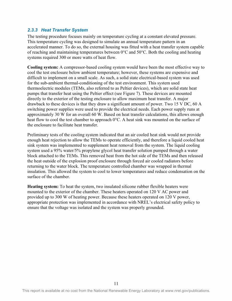
2.3.3 Heat Transfer System The testing procedure focuses mainly on temperature cycling at a constant elevated pressure. This temperature cycling was designed to simulate an annual temperature pattern in an accelerated manner. To do so, the external housing was fitted with a heat transfer system capable of reaching and maintaining temperatures between 0°C and 50°C. Both the cooling and heating systems required 300 or more watts of heat flow.
Cooling system: A compressor-based cooling system would have been the most effective way to cool the test enclosure below ambient temperature; however, these systems are expensive and difficult to implement on a small scale. As such, a solid state electrical-based system was used for the sub-ambient thermal-conditioning of the test environment. This system used thermoelectric modules (TEMs, also referred to as Peltier devices), which are solid state heat pumps that transfer heat using the Peltier effect (see Figure 7). These devices are mounted directly to the exterior of the testing enclosure to allow maximum heat transfer. A major drawback to these devices is that they draw a significant amount of power. Two 15 V DC, 60 A switching power supplies were used to provide the electrical needs. Each power supply runs at approximately 30 W for an overall 60 W. Based on heat transfer calculations, this allows enough heat flow to cool the test chamber to approach 0°C. A heat sink was mounted on the surface of the enclosure to facilitate heat transfer.
Preliminary tests of the cooling system indicated that an air cooled heat sink would not provide enough heat rejection to allow the TEMs to operate efficiently, and therefore a liquid cooled heat sink system was implemented to supplement heat removal from the system. The liquid cooling system used a 95% water/5% propylene glycol heat transfer solution pumped through a water block attached to the TEMs. This removed heat from the hot side of the TEMs and then released the heat outside of the explosion proof enclosure through forced air cooled radiators before returning to the water block. The temperature controlled chamber was wrapped in thermal insulation. This allowed the system to cool to lower temperatures and reduce condensation on the surface of the chamber.
Heating system: To heat the system, two insulated silicone rubber flexible heaters were mounted to the exterior of the chamber. These heaters operated on 120 V AC power and provided up to 300 W of heating power. Because these heaters operated on 120 V power, appropriate protection was implemented in accordance with NREL’s electrical safety policy to ensure that the voltage was isolated and the system was properly grounded.

12 This report is available at no cost from the National Renewable Energy Laboratory at www.nrel.gov/publications.
Figure 7. Thermoelectric module schematic
2.3.4 Automation The system was automated using a PLC that was used for both system control and data acquisition to allow for 24/7 operation. Separate temperature controllers with thermocouple feedback were used for heating and cooling the system. The temperature controllers were programmed to ramp to their programmed set points when turned on. Using solid state relays, the PLC would turn on and off the appropriate controller as needed. With this system, the experiment required no manual user input once a test was started. The PLC was also used for safety control of the system with an onboard hydrogen sensor and valve/venting control.
2.3.5 Pressurized System Components Medium pressure components rated to 15,000 psi were used for the hydrogen inlet to the PRDs. Pressurization of the PRDs was performed using the ESIF 12,000 psi hydrogen supply, which was reduced to 7,000 psi using a regulator at the inlet of the PRD test system. A pneumatic shut-off valve (i.e., the pneumatic supply valve in Figure 9) downstream from the regulator would open to allow hydrogen flow into the PRD test system and would close to isolate the upstream high pressure hydrogen. A series of shut-off valves maintained 7,000 psi hydrogen within the PRD test system. The system would lose a small amount of gas over time, so the pneumatic supply valve would be periodically activated to repressurize the system to 7,000 psi. The system was sufficiently leak tight such that repressurization was needed only after several weeks of operation. Typically repressurization was performed when there was a pressure loss of 50–100 psi. As shown in Figure 9, a pneumatic vent valve was directly connected to the vent, which allowed for the safe, remotely-activated depressurization in the event of an upset condition. The system was designed such that in the event of loss of power, the supply valve would default to the normally closed position to stop all flow of hydrogen from the high pressure source, whereas

13 This report is available at no cost from the National Renewable Energy Laboratory at www.nrel.gov/publications.
the vent valve would default to the normally open position to depressurize the test system. Operationally, the heating and cooling test protocol generated a pressure cycle of approximately 300 psi around the nominal 7,000 psi set point. The installation of the PRD test system in NREL’s high pressure test cell is shown in Figure 10.
Figure 8. Pressurized system components (front view)

14 This report is available at no cost from the National Renewable Energy Laboratory at www.nrel.gov/publications.
Figure 9. Pressurized system components (side view)
Figure 10. PRD apparatus installed in high pressure test cell (photo by NREL)

15 This report is available at no cost from the National Renewable Energy Laboratory at www.nrel.gov/publications.
2.4 Non-Destructive Examination Non-destructive examination can be used to support a manufacturing quality assurance program and as a field inspection procedure. Non-destructive examination can identify flaws and cracks that could create stresses that lead to premature failure. Prior to the accelerated life testing of the PRDs with 440C material, a computed tomography (CT) scan was conducted on the six valve nozzles. CT scanning is an X-ray technique capable of detecting subsurface flaws and inhomogeneity. The presence of a crack was indicated in a top view image of one nozzle (see Figure 11). This crack was on the outside diameter of the nozzle oriented in an axial direction. The defect was observed in 10 images that were each spaced by 0.02 mm for a total defect size of approximately 0.2 mm long by 6.2 mm deep. No defects were detected in the other five nozzle samples.
As previously stated, the test apparatus has the capability to test two valves concurrently. The two valves selected included the valve with the apparent preexisting defect and a valve with no defect as detected by CT scan imaging. The crack location on the outside diameter was not directly exposed to the pressurized hydrogen; however, hydrogen is able to be absorbed into and migrate within the 440C material and thus would likely be present throughout the material.
Figure 11. CT scan of 440C nozzle with indication of crack
S/N 586381, slice 98, 8.5659 mm (Nikon Metrology Inc.)

16 This report is available at no cost from the National Renewable Energy Laboratory at www.nrel.gov/publications.
3 Results 3.1 Temperature Cycling Test As described in Section 2.2.2, the temperature cycling was designed to achieve a 2X multiplication factor on a diurnal temperature variation. The data presented in Figure 12 show the “Air Temp” achieved in the temperature control chamber and the valve housing temperatures. The heating cycle rapidly achieved the target temperature. Forced convective heat transfer rates were achieved through air circulation fans mounted in the temperature control chamber. Temperatures A1, A2, and A3 were thermocouple measurements mounted on the base, body, and bonnet of one relief valve, respectively. Temperatures B1, B2, and B3 were from thermocouples similarly located on the second relief valve. The high thermal conductivity of the housings provided a nearly isothermal temperature across the housing wall. The base, body, and bonnet temperatures are nearly isothermal during the heating and cooling cycles, thereby validating the test method used to achieve target temperatures. The heating and cooling cycle duration was such that a near steady state temperature was achieved. This resulted in a heating cycle that was slightly shorter in duration than the cooling cycle based on differences in heating and cooling rates. This temperature control scheme achieved 10 temperature cycles in a 24 hour period. Figure 12 shows a 24-hour time slice of temperature data. A starting point of 25°C for the first cycle resulted in a slightly higher final temperature than successive cycles. The temperature profiles were very reproducible for the duration of the test.
Figure 12. Temperature cycle data

17 This report is available at no cost from the National Renewable Energy Laboratory at www.nrel.gov/publications.
3.2 PRD Failure A few months after the start of the temperature cycling test, there was a PRD failure that resulted in complete loss of pressure in the test system, releasing pressure through the vent line. The hydrogen sensor showed no indication of hydrogen release into the test enclosure. After 1,200 cycles (more than three years equivalent life) there was a low pressure alarm on the system, which resulted in system shutdown. The pressure data indicated the presence of a leak. It could not be determined which valve was leaking because the design of the apparatus had both vent lines connected with common instrumentation. Pressure data for the 480 minutes prior to failure are shown in Figure 13. The 300 psi peak to peak pressure variation is normal and has been attributed to the heating and cooling cycles of the closed volume of gas. An anomalous pressure decrease was observed approximately 20 minutes into a heating cycle. This pressure decay continued for 82 minutes until the low pressure alarm set point was reached. At this point the safety system activated the pneumatic vent valve to depressurize the test system and deactivated the temperature cycling. The test PRDs had pressure relief set points of 8,000 psi; the data showed no high pressure conditions that should have activated the PRD.
The rate of pressure loss was also inconsistent with the PRD pressure set point being reached; these valves were designed to fully open for fast depressurization when activated, whereas the observed pressure decay indicated a slow rate of leakage. One suspected failure mode was a crack in the 440C material. However, upon repressurization at ambient temperature, the valve held pressure, indicating structural integrity of the 440C material. At that point temperature cycles were resumed and the valve was found to hold pressure with no detectable leaks for the duration of the testing. These observations suggest that the leak was caused by a spurious but small opening in the valve seat.
Figure 13. Spurious pressure drop due to PRD failure
4000
4500
5000
5500
6000
6500
7000
7500
0 100 200 300 400 500
Pres
sure
(psi
)
Time (minutes)
Pressure/Time Plot
PT1

18 This report is available at no cost from the National Renewable Energy Laboratory at www.nrel.gov/publications.
Spurious openings are often attributed to an upset condition that allows the valve to open. These upset conditions are typically random and are proposed to be caused by a variety of suspected mechanisms. For example, it has been proposed that particulate or fluid contamination in the seat area can cause a valve failure. However, in this case the PRD was in a controlled laboratory environment so contamination as a root cause of failure is unlikely. Figure 14 shows a typical failure curve used in reliability engineering. There are three sections in such a curve corresponding to different failure mechanisms. In the first section failures due to manufacturing or component defects dominate, while in the third section component wearout is the dominant cause of failure. In the middle section failures tend to be caused by random events and thus are significantly harder to predict and control. The wearout failure mode was not observed in NREL’s testing, which would indicate that PRD life is greater than 10 years, although this prediction is based on a limited sample size of only two parts. Typically, life testing is conducted on a statistically significant sample size.
In Section 1.4, two failures of PRDs in the field were discussed. In the case of the NREL wind site PRD failure (case study reported in Section 1.4.3), it was suspected that the leakage was sufficient to produce flow forces that caused the valve to fully open. This is often the case for spurious openings because flow forces are designed to fully open the valve for quick venting in the case of an overpressure condition. This was a random failure. In contrast, the PRD failure at the bus fueling station (case study reported in Section 1.4.1) could be considered an early failure typical of a defective part or an incompatible material of construction. The wrong material was selected for the PRD nozzle, leading to embrittlement and early failure.
Figure 14. Typical component failure histogram
t (years)
Failures (t)
440C nozzle failure Leak failure End of Life >10 years
Wearout Failures
Random Failures

19 This report is available at no cost from the National Renewable Energy Laboratory at www.nrel.gov/publications.
3.3 Post-Test Inspection After completing the 10-year equivalent life accelerated life test, the valves were removed from the apparatus for a post-test inspection. Visual inspection did not show evidence of valve seat wear. Verification of the relief point showed that the valve still activated within the ±3% tolerance specified by ASME [ASME BPVC Section VIII Division 1 Paragraph UG-126 (d)]. Verification of the PRD set point was performed by an outside vendor. During such maintenance activity, the vendor typically replaces internal wear parts; however, explicit instructions were given to not replace or interchange any components in the PRDs. Upon return to NREL, the 440C nozzles were sent out for a post-test CT scan inspection. Particular attention was paid to the region that indicated a preexisting crack. The post-test inspection did not show evidence of the crack, suggesting that the pretest results may have been an anomaly within the initial CT scan (shadows and other artifacts do occur in CT scans that can be misinterpreted as a physical feature). Another possible explanation for the inconsistency in CT scan data could be that the nozzle parts were not properly tagged by the outside vendor during verification of the pressure relief set point; however there is no evidence that this was the case.
3.4 Implications for Component Level Qualification Testing Qualification tests for high pressure applications are being developed by Standards Development Organizations (SDOs) so that certificates of compliance can be issued for components and systems. Component level standards are designed to provide a minimum level of product safety and reliability. Producers include quality control and quality assurance processes to provide further assurance that the components will meet the expectations of the market. Cyclical testing in hydrogen is being written into the standards to provide this first level of product safety. These qualification tests are based upon accelerated life testing methods designed to provide assurance that parts will survive real-world conditions. However, in many cases the correlation between accelerated life tests and field performance has yet to be empirically established, which requires cooperation among the critical stakeholders including manufactures, end users, SDOs, and independent arbitrators such as the national labs.
A second hindrance to certification pertains to cost and practicality of specific test requirements. The temperature cycling test procedure described here requires one year of continuous operation in order to achieve a 10-year equivalent life time. Although representative of the actual operating conditions, a one-year test is impractical for routine testing and certification; however, such testing does support research into failure mode mechanisms. However, thermal cycle testing is commonly used in electronics testing where the mass is small so the heating time is short. Thermal transients for PRDs and other high pressure components are too slow for consideration when defining qualification tests. For these reasons, pressure cycle tests are more typically being defined for PRD qualification requirements.
The temperature cycle tests presented here were not able to reproduce the 440C material failure even though the accelerated testing was representative of expected stresses experienced during a 10-year life time. The inability of this accelerated life test to produce a failure in a material that is known to exhibit a high degree of hydrogen embrittlement suggests that cycle testing in high pressure hydrogen may not be sufficient to reproduce a known failure of this type. There are other factors, such as the preexisting conditions that may contribute to material stability. A future proposed test is to add a notch on the 440C nozzle to simulate accelerated failure in a flawed

20 This report is available at no cost from the National Renewable Energy Laboratory at www.nrel.gov/publications.
part. The use of a notch is a standard metallurgical procedure for ascertaining relative hydrogen compatibility of materials. An understanding of the crack growth rate can support material specification for components. The information from such test designs could be helpful in understanding quality control and quality assurance requirements for component manufacturing.
3.4.1 Understanding Material Failure Designing PRDs for high pressure hydrogen environments requires an understanding of the potential effects of hydrogen damage on the strength of materials (Craig 2003).
Fracture mechanics approach: Fracture mechanics is a method to determine a material’s resistance to fracture by quantifying a crack’s susceptibility to growth. Material embrittlement reduces localized yielding (ductility) along the crack, which reduces the ability of the part to distribute the load, which in turn leads to an increased likelihood of failure. A material that lacks preexisting flaws (e.g., no cracks) or is not subjected to crack initiation during operation may function in hydrogen. However, the presence of flaws in a material may enhance the failure rate for flaws above a critical threshold. Hydrogen embrittlement was identified as a contributing factor for the PRD 440C nozzle failure described in Section 1.4.1 (Harris and San Marchi 2012).
Design with brittle material: Brittle materials are routinely used in many applications; examples include glass, ceramics, and composites. In general the use of brittle materials requires an understanding of the failure modes and adherence to quality control and quality assurance processes. A crack in brittle material can rapidly grow to failure, so frequent inspections for crack growth are required. Acoustic monitoring, which is one means to monitor for crack growth, has been shown to be effective for in-situ inspection when using brittle material. Design features such as wall thickness can alleviate risk of failure due to embrittlement.
Crack initiation: Cracks tend to propagate quickly in brittle materials because at the crack tip there is little ductility to absorb and distribute the energy. Thus, eliminating causes of crack formation is used to improve the reliability of brittle materials. This can be as simple as the application of coatings that can absorb or otherwise distribute impact loads, or the use of protective filters to minimize damage by impact loads.
3.4.2 Codes and Standards Methods Codes and standards for hydrogen components in both stationary and vehicle applications are being developed to provide assurance that products are prequalified for reliable service through end of life. The general methodology is to require acceptance level tests that combine accelerated life tests in hydrogen with durability tests and material qualification tests. A good example of the methodology is the SAE J2579 standard for onboard compressed hydrogen systems with reference to CSA CHMC 1 for hydrogen compatibility testing.
3.5 Findings of the NREL PRD Failure Investigation As summarized in section 1.4.3, a PRD failed that was located on a 3,500 psi hydrogen storage tank at an NREL hydrogen demonstration site. A failure investigation was conducted to determine the root cause. This investigation involved a review of operations data, inspection of PRDs and system components, and shipment of the valve back to the manufacturer for further evaluation.

21 This report is available at no cost from the National Renewable Energy Laboratory at www.nrel.gov/publications.
The post-test manufacturer’s evaluation included testing the operation of the valve to the set pressure. The valve set point was shown to be within the ±3% ASME tolerance. Note that the valve was inspected under laboratory conditions and no attempt was made to recreate the cold outdoor ambient conditions that the valve experienced during failure. Disassembly inspection showed that all internal parts were within the manufacturer’s specification. Discussion between NREL and the manufacturer led to the conclusion that contamination (or possibly freeze/thaw moisture) was a possible cause for PRD failure. In this scenario, the valve is able to open even though the pressure is below the set point. The flowing gas provides additional opening force that can cause the valve to actuate to a full open position. The expanding gas creates a low temperature that causes the valve to stick in place either through thermal contraction or condensation freezing. The relief valve is frozen open and thus not able to reseat as the pressure drops in the storage vessel. The high flow rate achieved during the pressure venting is able to remove any evidence of the contamination that caused the initial valve opening.
Corrective actions as a result of this investigation include the following:
• Consider the removal of PRDs from stationary storage where appropriate. Risk can be defined as the product of the probability and severity of an out-of-normal event. In the case of stationary hydrogen storage, the risk associated with a PRD failure has been compared against the risk of not having a PRD. It has been argued that the overall risk is lower with no PRD on the stationary storage. PRDs should be located at the sources of potential overpressure, such as the discharge of a compressor. In many cases, there is negligible probability of an overpressure on a stationary storage container, such that adding a relief valve will actually increase the risk because of the failure rate of PRDs. Removing the PRD requirements for U.S. Department of Transportation Pipeline and Hazardous Materials Safety Administration (PHMSA) transport in standard CGA S1.1 is proposed by CGA. CGA recommendations are based on a study of PRD reliability (Barlen 2006) that included bonfire testing of storage containers. This testing showed that the burst failure mode could not be achieved, and that under bonfire conditions the PRD would not see sufficient pressure to actuate. The CGA proposal to PHMSA to remove requirements for PRDs is under review at the time of this report.
• PRD predictive maintenance program. As part of the corrective action surrounding this PRD failure, NREL’s Compressed Gas Safety Panel in conjunction with the NREL Metrology Lab have initiated a pilot program to test and recertify compressed gas PRDs across the lab. This program supplies spare relief devices to install while PRDs are removed from service and recertified by the calibration lab. The recertification typically includes replacing seating materials and other wear parts in the valve. The recertification cycle is based upon the severity of service of the PRD and historical record of failure.

22 This report is available at no cost from the National Renewable Energy Laboratory at www.nrel.gov/publications.
4 Conclusions and Recommendations PRDs are devices used for passive overpressure protection on pressurized systems, both for stationary storage and for over the road transportation cylinders. These devices are known to exhibit reliability concerns, disrupting system operation, as described in several case studies (Harris and San Marchi 2012, Alkhaldi 2003, Barlen 2006). NREL has experienced PRD failure in full scale hydrogen demonstration systems, thereby providing the opportunity to collect field failure data and to gain an understanding of the challenges experienced in early market hydrogen system deployment. PRDs that open prematurely and release process gas up a vent stack are generally not a serious safety concern at industrial sites, but can be a potential issue at hydrogen fueling stations and on transport vessels due to the close proximity to the general public and other structures. Conversely, PRDs that are stuck closed are a more serious safety concern because the system can potentially experience an unprotected overpressure condition.
In order to understand how PRDs can be safely used in high pressure hydrogen applications, NREL investigated PRD reliability issues by (1) conducting PRD accelerated life testing on a valve with a known failure mode, (2) examining case studies to further understand PRD failure modes, and (3) reviewing industry best practices for PRD applications.
The PRD accelerated life testing has shown that controlled laboratory temperature cycles were not able to duplicate a known field failure. The known failure was attributed to an improper selection of the material of construction for the PRD, notably the selection of a hard material for the nozzle. Selection of materials for use in a hydrogen environment requires an understanding of the interaction of hydrogen on the material and the stresses experienced during operation. Material selection may benefit from prequalification by conducting testing as defined in CSA CHMC 1 (CSA 2014). As discussed in this report, materials such as stainless steel 440C are known to have embrittlement issues in hydrogen service. There are limitations to the performance-based approach in prequalification assurance testing. Within this study, the end of life equivalent accelerated life testing performed on two relief valves with 440C nozzles was not able to reproduce the known field failure. The necessary conditions required to reproduce the nozzle field failure may include part-to-part variation such as stress concentration, non-homogeneous material, or other preexisting condition. In order to identify non-conforming material in the nozzle, a non-destructive CT Scan examination was conducted pre- and post-test, but results were inconclusive. It is important to understand the challenges of using a specific material in hydrogen service. Quality control and quality assurance processes can be used to identify non-conforming flaws and residual stresses that could lead to crack growth and failure. For example, fracture mechanics methods are used to verify integrity of pipeline steels known to be subjected to embrittlement from hydrogen and other embrittling gases such as hydrogen sulfide (Anderson 2005).
Engineering and administrative controls should be used as part of a preventive maintenance plan to assure PRD reliability. Maintenance should include rebuilding the PRD at regular service intervals, installing new o-rings, gaskets, and seating materials, resetting the pressure set point, and certifying the rebuilt PRD. These engineering and administrative controls are a generally accepted practice in the process gas industry.

23 This report is available at no cost from the National Renewable Energy Laboratory at www.nrel.gov/publications.
The lessons learned on PRD reliability are being used to improve the way PRDs are being applied. The CGA study discussed in Section 3.5 (Barlen 2006) made some relevant conclusions about the reliability of relief devices (in this case rupture disks) on PHMSA transport cylinders. Results of the study were used to argue that relief devices on transport gas storage vessels should be removed due to the potential for inadvertent failure. A hazard analysis demonstrated that the risk associated with a PRD failure was greater than the risk of a pressure vessel burst failure. In support of this analysis, CGA conducted engulfing fire testing on transport cylinders to verify their proposal to remove PRD requirements on PHMSA cylinders (Barlen 2006). Requirements were changed in CGA S-1.1:2011 (14th Edition) noting that, for hydrogen, using a CG-1 pressure relief disk is optional on hydrogen tubes. CGA has submitted this publication to PHMSA for referencing. However, the current edition that is referenced in 49CFR173.301(f) is the 2005 Edition. Similarly, NREL is looking at ways to improve the safe use of hydrogen by reviewing the need for PRDs on NREL high pressure stationary storage systems. NREL has also instituted a lab-wide preventive maintenance plan for regular recertification service intervals for PRDs.
Performance-based testing methodologies and test protocols that are used in codes and standards are based on an understanding of failure modes and the required safety margin. Further testing is needed to better understand PRD failure modes. Accelerated life testing could include adding notches to the test material to gain a better understanding of the necessary stress concentrations required for reproducing a known field failure. This would also provide information on acceptable crack sizes when conducting quality inspections for either routine factory testing or for in-the-field preventative maintenance.
In summary, these test results show that PRD failure modes in hydrogen service do not originate from a single root cause; that understanding material failure issues specific to hydrogen is important for component failure prediction in high pressure service; and that the use of performance-based component level tests may not reveal all insufficiencies for design qualification purposes.

24 This report is available at no cost from the National Renewable Energy Laboratory at www.nrel.gov/publications.
References Alkhaldi, M. 2004. “The Hidden Facts of Process Safety Valve Reliability.” International Fertilizer Industry Association Technical Conference Proceedings, Beijing, April 20-23, 2004. Available at http://www.fertilizer.org/en/images/Library_Downloads/2004_tech_beijing_alkhaldi.pdf.
American Petroleum Institute. 2009. “Inspection of Pressure-Relieving Devices.” Recommended Practice RP-576, Third Edition.
Anderson, T.L. 2005. Fracture Mechanics: Fundamentals and Applications. 3rd Edition, New York: CRC Press.
Barlen, W. 2006. “Compressed Gas Industry Fire Test.” Unpublished report, May 18, 2006, and personal communication.
CGA S1.1. 2007. “Pressure Relief Device Standards-Part 1-Cylinders for Compressed Gases.” Thirteenth Edition, Compressed Gas Association Publication, Chantilly, Virginia.
Craig, B. 2003. “Hydrogen Damage.” In ASM Handbook Volume 13A, Corrosion: Fundamentals, Testing, and Protection, edited by S.D. Cramer and B.S. Covino, Jr. Materials Park, Ohio: ASM International.
CSA. 2014. “Test methods for evaluating material compatibility in compressed hydrogen applications – Metals.” ANSI/CSA CHMC 1, Canadian Standards Association Publication, Toronto, Ontario.
Harris, A. and C. San Marchi. 2012. Investigation of the Hydrogen Release Incident at the AC Transit Emeryville Facility (Revised). SAND2012-8642. Livermore, California: Sandia National Laboratories.
Kostival, A. et al. 2014. Pressure Relief Device Accelerated Life Testing Experiment Design. NREL Internal Report.

25 This report is available at no cost from the National Renewable Energy Laboratory at www.nrel.gov/publications.
Bibliography Air Products. 1999. “Safetygram-15 Cylinder Pressure Relief Devices.”
Alkhaldi, M. 2004. “The Hidden Facts of Process Safety Valve Reliability.” International Fertilizer Industry Association Technical Conference Proceedings, Beijing, April 20-23, 2004. Available at: http://www.fertilizer.org/en/images/Library_Downloads/2004_tech_beijing_alkhaldi .pdf.
American Petroleum Institute. 2009. “Inspection of Pressure-Relieving Devices.” Recommended Practice RP-576, Third Edition, American Petroleum Institute.
Anderson, T.L. 2005. Fracture Mechanics: Fundamentals and Applications. 3rd Edition. New York: CRC Press.
Barlen, W. 2006. “Compressed Gas Industry Fire Test.” Unpublished report, May 18, 2006, and personal communication.
Burgess, R. et al. 2016. “Hydrogen Component R&D.” Poster presentation at the 2016 DOE Hydrogen and Fuel Cells Program Annual Merit Review and Peer Evaluation Meeting, June 6–10, 2016.
Burgess, R. et al. 2016. Pressure Relief Device Accelerated Life Testing Project Plan. NREL AOP Report, January 2016.
Burgess, R. et al. 2015. Pressure Relief Device Reliability – Potential Failure Modes and Test Results. NREL AOP Milestone Report, June 2015.
CGA S1.1. 2011. “Pressure Relief Device Standards-Part 1-Cylinders for Compressed Gases.” Fourteenth Edition. Compressed Gas Association Publication, Chantilly, Virginia.
CGA S1.2. 2009. “Pressure Relief Device Standards-Part 2-Portable Containers for Compressed Gases.” Ninth Edition. Compressed Gas Association Publication, Chantilly, Virginia.
CGA S1.3. 2008. “Pressure Relief Device Standards-Part 3-Stationary Storage Containers for Compressed Gases.” Eighth Edition. Compressed Gas Association Publication, Chantilly Virginia.
CSA. 2014. “Test methods for evaluating material compatibility in compressed hydrogen applications – Metals.” ANSI/CSA CHMC 1, Canadian Standards Association Publication, Toronto, Ontario.
H2Tools. 2013. “Pressure Relief Device Fails at Fueling Station.” DOE Hydrogen Tools Database, available at https://h2tools.org/lessons.
H2Tools. 2010. “Tube Trailer Leak through Over-Pressure-Protection Rupture Disk.” DOE Hydrogen Tools Database, available at https://h2tools.org/lessons.
26 This report is available at no cost from the National Renewable Energy Laboratory at www.nrel.gov/publications.
H2Tools. 2010. “Unexpected Failure of Rupture Disk on Liquid Hydrogen Tank at Manufacturing Plant.” DOE Hydrogen Tools Database, available at https://h2tools.org/lessons.
H2Tools. 2010. “High-Pressure Burst Disk Failure.” DOE Hydrogen Tools Database, available at https://h2tools.org/lessons.
H2Tools. 2009. “Hydrogen Tube Trailer Burst Disc Ruptures Prematurely While Filling.” DOE Hydrogen Tools Database, available at https://h2tools.org/lessons.
H2Tools. 2008. “Hydrogen Explosion at Coal-Fired Power Plant.” DOE Hydrogen Tools Database, available at https://h2tools.org/lessons.
Harris, A. and C. San Marchi. 2012. Investigation of the Hydrogen Release Incident at the AC Transit Emeryville Facility (Revised). SAND2012-8642. Livermore, California: Sandia National Laboratories.
Klutke, Kiessler and Wortman. 2003. IEEE Transactions on Reliability, vol. 52, no. 1, pp. 125-129.
Kostival, A. et al. 2014. Pressure Relief Device Accelerated Life Testing Experiment Design. NREL Internal Report, February 2014.
Kostival, A. et al. 2013. Pressure Relief Devices for High-Pressure Gaseous Storage Systems: Applicability to Hydrogen Technology. NREL Technical Report NREL/TP-5400-60175, November 2013.
Matheson Gas. 2011. “Safe Handling of Compressed Gases in the Laboratory and Plant.”
McDougall, M. 2011. HPRD1 Hydrogen Service Suitability Test Validation Program. Powertech Final Report, Project #19588-34, September 2011.
Los Alamos National Laboratory. 2000. “Hydrogen Gas Safety.”
Peters, M. et al. 2016. “Overview of an Integrated Research Facility for Advancing Hydrogen Infrastructure.” Oral presentation at the 2016 DOE Hydrogen and Fuel Cells Program Annual Merit Review and Peer Evaluation Meeting, June 6–10, 2016.
Sunderland, P.B. 2008. “Pressure Relief Devices for Hydrogen Vehicles.” Presented at the Third European Summer School on Hydrogen Safety July 21-30, 2008.