pressure regulators, rhps series
TRANSCRIPT
Pressure Regulators—RHPS Series 1 RHPS
REGULATORS
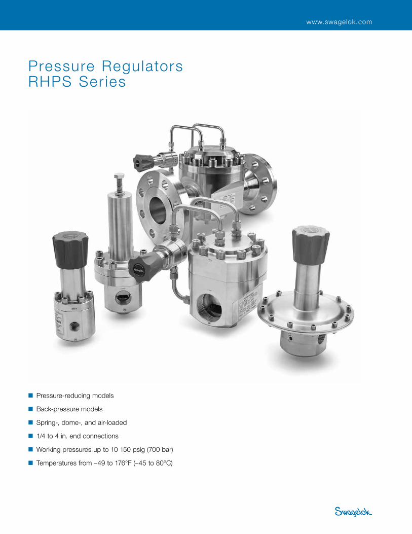
Pressure Regulators RHPS Ser ies
■ Pressure-reducing models
■ Back-pressure models
■ Spring-, dome-, and air-loaded
■ 1/4 to 4 in. end connections
■ Working pressures up to 10 150 psig (700 bar)
■ Temperatures from –49 to 176°F (–45 to 80°C)
www.swagelok.com

2 Pressure Regulators and FiltersRH
PS
REGU
LATO
RS
ContentsFeatures, 4
Types of Regulators, 5
Terminology, 5
Components, 6
Testing, 7
Cleaning and Packaging, 7
Pressure-Reducing Regulators
Dome-Loaded—RD Series, 43
Pressure-Reducing Regulators
Spring-Loaded—RS Series, 8
Compact, General-Purpose RS(H)2 Series, 10
General-Purpose RS(H)4, 6, 8 Series, 14
General-Purpose RS(H)10, 15, 20 Series, 22
High-Sensitivity LRS(H)4 Series, 29
High-Sensitivity LPRS4, 6, 8 Series, 33
High-Sensitivity LPRS10, 15 Series, 38
Compact, General-Purpose RD2 Series, 46
General-Purpose RD(H)6, 8 Series, 50
Differential RD(H)6DP Series, 55
Integral Pilot-Operated RD(H)20, 25 Series, 72
Integral Pilot-Operated RD(H)10, 15 Series, 59
RD Series Maintenance Kits, 106RS Series Maintenance Kits, 42

Pressure Regulators—RHPS Series 3 RHPS
REGULATORS
Back-Pressure Regulators
Spring-Loaded—BS Series, 107
Air-Loaded RA4, 6, 8 Series, 101
Pressure-Reducing Regulators
Dome-Loaded—RD Series
Compact, General-Purpose BS(H)2 Series, 109
General-Purpose BS(H)4, 6, 8 Series, 113
General-Purpose BS(H)10, 15 Series, 118
High-Sensitivity LBS4 Series, 124
Back-Pressure Regulators
Dome-Loaded—BD Series
Contact your authorized Swagelok sales and service representative for information about dome-loaded, back-pressure regulators.
Integral Pilot-Operated, High-Sensitivity LPRD20, 25, 30, 40 Series, 99
Integral Pilot-Operated RD(H)30, 40 Series, 84
BS Series Maintenance Kits, 128

4 Pressure Regulators and FiltersRH
PS
REGU
LATO
RS
Features
Set-Pressure Spring ■provides pressure control
across a wide range of flow rates
■ long spring improves droop performance.
Diaphragm Support Plate promotes diaphragm life. Inlet Outlet
Piston Sensing Mechanism■typically used to regulate higher
pressures than a diaphragm sensing mechanism
■more resistant to damage caused by pressure spikes
■designed with a short stroke to maximize cycle life.
Threaded Vent allows monitoring of the diaphragm or piston sensing mechanism.
Bottom Spring Guide■engages diaphragm to distribute
forces evenly■protects diaphragm from
premature failure.
Diaphragm Sensing Mechanism ■typically used in low outlet
pressure applications■provides greater accuracy
in sensing changes in outlet pressure
■available in PTFE and a variety of elastomers
■designed with a short stroke to maximize cycle life.
Body Plugallows for easy maintenance and more up-time.
Balanced Poppet Designreduces supply-pressure effect and lockup.
Seat Seal Materialsavailable in PCTFE, PEEK, and a variety of elastomers.
Seal Materials available in a variety of materials for enhanced chemical compatibility in a wide range of applications.
Body Material 316L SS for improved corrosion resistance.
Regulator Adjusting Screw
Fine pitched threads provide improved adjustability and resolution when setting or adjusting pressure.
Piston
Piston plate
WARNING: Threaded-vent regulators can release system fluid to atmosphere. Position the threaded vent connection away from operating personnel.

Pressure Regulators—RHPS Series 5 RHPS
REGULATORS
The function of a pressure-reducing regulator is to reduce a pressure and to keep this pressure as constant as possible while the inlet pressure and the flow may vary. This is accomplished by the fluid force (F) being equal to or slightly lower than load force (FS) causing the poppet to open.
The function of a back-pressure regulator is to keep inlet pressure below a set pressure. This means the regulator can either open in case of excess pressure or close when the pressure drops below a desired pressure. This is accomplished by the fluid force (F) being equal to or slightly lower than load force (FS) causing the poppet to close.
TerminologyAccumulation—an increase in inlet pressure caused by an
increase in flow rate to a back-pressure regulator.
Creep—an increase in outlet pressure typically caused by regulator seat leakage.
Dependency—see supply pressure effect (SPE).
Droop—a decrease in outlet pressure caused by an increase in flow rate to a pressure-reducing regulator.
Lockup—an increase in outlet pressure that occurs as the flow rate is decreased to zero.
Self-venting—a feature that reduces outlet pressure in a pressure-reducing regulator when the regulator set point is decreased and there is no flow through the regulator.
Sensitivity—the degree to which the regulator responds to force balance changes.
Set pressure—the desired outlet pressure of a pressure-reducing regulator, normally stated at a no-flow condition.
Supply pressure effect (SPE)—the effect on the set pressure of a pressure-reducing regulator as a result of a change in inlet pressure, normally experienced as an increase in outlet pressure due to a decrease in inlet pressure. Also known as Dependency.
Threaded vent—a connection that allows monitoring of the diaphragm or piston sensing mechanism.
Types of RegulatorsThere are two types of RHPS series pressure regulators
■Pressure-reducing regulators with spring or dome loading
■Back-pressure regulators with spring or dome loading
Inlet pressureOutlet pressure
Inlet pressureOutlet pressure
FS = Spring forceF = Fluid force / outlet pressure
FS = Spring forceF = Fluid force / outlet pressure
F
Inlet
Outlet
FS
F
Inlet
Outlet
How a Pressure Regulator WorksA pressure regulator has a sensing element (piston or diaphragm) which, on one side, is subjected to a load force (FS) created by a spring (as shown below) or a gas pressure. On the other side, the sensing element is subject to the force (F) of the system fluid.
Gauge Connection Configuration Symbols
Pressure-Reducing Regulators Back-Pressure Regulators
Gi = Inlet gauge Go = Outlet gauge
Inlet Outlet
Go GiGoGo Gi Go
Gi Gi GoGi Gi Go
Gi Go GiGi Gi Go
std
Pressure reducing
Back Pressure
std
Go GiGoGo Gi Go
Gi Gi GoGi Gi Go
Gi Go GiGi Gi Go
std
Pressure reducing
Back Pressure
std
FS
Gauge Connection Configurations—Pressure-Reducing Regulators
Standard GN2 GN4 GN5
Go GiGoGo Gi Go
Gi Gi GoGi Gi Go
Gi Go GiGi Gi Go
std
Pressure reducing
Back Pressure
std

6 Pressure Regulators and FiltersRH
PS
REGU
LATO
RS
Dome-LoadedIn a dome-loaded regulator, a gas is fed into the dome chamber above the sensing mechanism at a pressure equal to or slightly above the required outlet pressure. This volume of gas is used like a spring. The dome pressure (Fd ) is typically supplied by a second regulator called a pilot regulator.
Combination Spring- and Dome-LoadedThe spring- and dome-loaded mechanisms can be used in combination with one another. The resulting effect provides the function of a differential pressure regulator. This regulator is designed to control pressure which is the sum of a reference pressure (provided by the dome) and a bias pressure (provided by the spring). See RD(H)6DP series on page 55 for details.
Loading MechanismThe loading mechanism is the component of the regulator that balances the force or pressure.
Every RHPS series pressure regulator has three common design components:
■Loading mechanism (spring, dome, or combination spring and dome)
■Sensing mechanism (diaphragm or piston)
■Controlling mechanism (poppet)
Components
FS or Fd ≤ F
F
F
Spring-Loaded In a spring-loaded regulator, a coil spring is used to generate a load (FS ) against the sensing mechanism. The amount of spring force or load can be adjusted by turning the handle or adjusting screw of the regulator.
Poutlet
Poutlet
Poutlet
Poutlet
F
Fd
F
FS or Fd > F
Fd
Pinlet
Pinlet
Pinlet
Pinlet
Closed
Open
FS
FS

Pressure Regulators—RHPS Series 7 RHPS
REGULATORS
Sensing MechanismsThe sensing mechanism is the component separating the spring/dome force and the fluid force. It senses changes in pressure and allows the regulator to react and to try to restore the original set pressure.
■ Diaphragm Sensing The diaphragm is a large, flat
piece of material usually made of an elastomer, PTFE, or metal depending on the application. A diaphragm is normally used for low control-pressure applications in spring-loaded regulators and in all dome-loaded regulators.
■ Piston Sensing A piston is a cylindrical metal
component which is generally used to regulate higher control pressures than a spring-loaded regulator with a diaphragm. They are also more resistant to damage caused by pressure spikes.
Seat DesignThe poppet within the RHPS series regulator can have a hard or soft seat seal depending on the pressure requirements of the application.
■ Soft Seat Seal A soft seat seal is designed to
regulate pressures up to 1015 psig (70.0 bar). The seat seal materials are generally elastomeric, and include fluorocarbon FKM, perfluorocarbon FFKM, nitrile, and EPDM.
■Hard Seat Seal A hard seat seal is designed
to regulate pressures up to 10 150 psig (700 bar). The seat seal materials are PCTFE for pressures up to 5800 psig (400 bar) and PEEK for pressures up to 10 150 psig (700 bar).
Controlling MechanismsThe controlling mechanism, also known as a poppet, acts to reduce a high inlet pressure to a lower outlet pressure. There are two designs used in RHPS regulators.
■ Balanced Poppet In a balanced poppet design,
the area on which the inlet pressure acts is reduced due to the orifice through the poppet and balancing O-ring. The advantages of this design are a reduced seat load, less sensitivity to SPE, and the ability to have a larger seat for more flow.
■ Unbalanced Poppet In an unbalanced poppet
design, the inlet pressure provides the majority of the shutoff force. Unbalanced poppets are generally used in small regulators or larger regulators in low-pressure applications.
TestingEvery RHPS series regulator is factory tested with nitrogen or air. Shell testing is performed to a requirement of no detectable leakage with a liquid leak detector.
Cleaning and PackagingEvery RHPS series regulator is cleaned and packaged in accordance with Swagelok Standard Cleaning and Packaging (SC-10) catalog, MS-06-62.
Cleaning and packaging to ensure compliance with product cleanliness requirements stated in ASTM G93 Level C is available.
Oxygen Service HazardsFor more information about hazards and risks of oxygen-enriched systems, refer to Swagelok Oxygen System Safety technical report, MS-06-13.
• RHPS series pressure regulators are not “Safety Accessories” as defined in the Pressure Equipment Directive 2014/68/EU.
• Do not use the regulator as a shutoff device.
• WARNING: Self-venting and threaded-vent regulators can release system fluid to atmosphere. Position the self-vent hole or the threaded vent connection away from operating personnel.
BAR BAR
Seatseal
BAR BAR
Seat seal
BAR BAR
Diaphragm
BAR BAR
Piston
Inlet
Orifice Outlet
Inlet
Outlet
Components
O-ring

8 Pressure Regulators and FiltersRH
PS
REGU
LATO
RS
The RS series pressure-reducing regulators are suitable for most gases and liquids. The RS series regulators feature various poppet designs, a choice of sensing types (diaphragm or piston), and seat and seal materials to accommodate a variety of pressure, temperature, and flow conditions.
The RS series regulators are available in sizes from 1/4 to 2 in. with a choice of threaded or flange end connections.
The RSH series regulators are a high-pressure version of the RS series regulators, and the LRS and LPRS series are low-pressure, high-accuracy versions of the RS series regulators.
The RS series regulators are available with many options, including a variety of gauge connection configurations, self venting, internal filter, external feedback, antitamper, special cleaning to ASTM G93 Level C, and NACE MR0175/ISO 15156-compliant models.
Pressure-Reducing, Spring-Loaded Regulators—RS Series
Features■Spring-loaded pressure control
■Diaphragm or piston sensing mechanisms
■Red knob handle or screw adjustment
■316L stainless steel materials of construction for corrosion resistance
■Maximum inlet pressure ratings: 232 to 10 150 psig (16.0 to 700 bar)
■Pressure control ranges: Up to 0 to 10 150 psig (0 to 700 bar)
Technical Data—Performance
Series
Maximum Inlet Pressure➀
psig (bar)
Maximum Outlet Control Pressure➀
psig (bar)
Flow Coefficient
(Cv )Sensing
Type
Flow Data
on Page
RS2 5 800 (400) 5 075 (350)0.05 Piston 11
RSH2 10 150 (700) 10 150 (700)
RS4 1 015 (70.0) 406 (28.0) diaphragm5 800 (400) piston 1.84 Diaphragm
or piston 15RSH4 5 800 (400)
RS6 1 015 (70.0) 203 (14.0) diaphragm5 800 (400) piston 1.95 Diaphragm
or piston 17RSH6 5 800 (400)
RS8 1 015 (70.0) 203 (14.0) diaphragm5 800 (400) piston 2.07 Diaphragm
or piston 20RSH8 5 800 (400)
RS10 1 015 (70.0) 290 (20.0) diaphragm3 625 (250) piston 3.79 Diaphragm
or piston 23RSH10 5 800 (400)
RS15 1 015 (70.0) 290 (20.0) diaphragm3 625 (250) piston 7.30 Diaphragm
or piston —RSH15 5 800 (400)
RS20 1 015 (70.0)290 (20.0) 13 Diaphragm —
RSH20 5 800 (400)
LRS4 507 (35.0)290 (20.0)
0.73Diaphragm
30
LRSH4 5 800 (400) 0.10 31
LPRS4
232 (16.0) 43 (3.0)
1.84
Diaphragm —LPRS6 1.95
LPRS8 2.07
LPRS10232 (16.0) 43 (3.0)
3.79Diaphragm
39
LPRS15 7.30 39
RS(H)2
RS(H)4, 6, 8
RS(H)10, 15, 20
LRS(H)4
LPRS4, 6, 8
LPRS10, 15 ➀ Regulator pressure rating may be limited by end connection type.
Pressure-Temperature Ratings
Seal Material Temperature Range
°F (°C) Material
Designator
Fluorocarbon FKM 5 to 176 (–15 to 80) V
Standard Nitrile -4 to 176 (–20 to 80) N
Low-Temp Nitrile -49 to 176 (–45 to 80) L
EPDM -4 to 176 (–20 to 80) E
FFKM 14 to 176 (–10 to 80) F
Seat Material PCTFE PEEKFluorocarbon FKM,
Nitrile, EPDM, FFKM
Temperature °F (°C)
Maximum Inlet Pressure / Working Pressure psig (bar)
-49 to -40 (–45 to -40) – –
1015 (70.0)
-40 to -4 (–40 to -20)5800 (400)
5800 (400)
95 (35)
10 150 (700)149 (65) 3987 (275)
176 (80) 1812 (125)

Pressure Regulators—RHPS Series 9 RHPS
REGULATORS
Inlet Outlet
Soft seat design for low-pressure
applications
RSH Series Regulator with Piston Sensing
and Antitamper Option
RS Series Regulator with Diaphragm Sensing
and Standard Knob Handle
Hard seat design for high-pressure
applications
Inlet Outlet
Technical Data—Design
Series
Seat Diameterin. (mm) Inlet and Outlet Connections Gauge Connection
Weight (Without Flanges)
lb (kg)
More Information
on Page
RS2 0.087 (2.2) 1/4 in. NPT 1/4 in. NPT 3.3 (1.5) 10
RSH2
RS4 0.39 (10.0) 1/2 in. NPT, ISO/BSP parallel thread, EN or ASME flanges 1/4 in. NPT 7.7 (3.5) 14
RSH4
RS6 0.39 (10.0) 3/4 in. NPT, ISO/BSP parallel thread, EN or ASME flanges 1/4 in. NPT 9.9 (4.5) 14
RSH6
RS8 0.39 (10.0) 1 in. NPT, ISO/BSP parallel thread, EN or ASME flanges 1/4 in. NPT 9.9 (4.5) 14
RSH8
RS10 0.55 (14.0)1 in. NPT, ISO/BSP parallel thread, EN or ASME flanges 1/4 in. NPT or
ISO/BSP parallel thread 16.5 (7.5) 22RSH10 0.53 (13.5)
RS15 0.75 (19.0) 1 1/2 in. NPT, ISO/BSP parallel thread, EN or ASME flanges 1/4 in. NPT or
ISO/BSP parallel thread 22.0 (10.0) 22RSH15
RS20 0.98 (25.0) 2 in. NPT, ISO/BSP parallel thread, EN or ASME flanges ISO/BSP parallel thread 39.6 (18.0) 22
RSH20
LRS4 0.23 (6.0) 1/2 in. NPT 1/4 in. NPT 5.7 (2.6) 29
LRSH4 0.087 (2.2)
LPRS4
0.39 (10.0)
1/2 in. NPT, ISO/BSP parallel thread, EN or ASME flanges
1/4 in. NPT
11.0 (5.0)
33LPRS6 3/4 in. NPT, ISO/BSP parallel thread, EN or ASME flanges 12.1 (5.5)
LPRS8 1 in. NPT, ISO/BSP parallel thread, EN or ASME flanges 12.1 (5.5)
LPRS10 0.55 (14.0) 1 in. NPT, ISO/BSP parallel thread, EN or ASME flange 1/4 in. NPT or ISO/BSP parallel thread
17.6 (8.0)38
LPRS15 0.75 (19.0) 1 1/2 in. NPT, ISO/BSP parallel thread, EN or ASME flanges 22.0 (10.0)
Pressure-Reducing, Spring-Loaded Regulators—RS Series

10 Pressure Regulators and FiltersRH
PS
REGU
LATO
RS
Features■Bottom mounting
■Sealed spring housing
■Low-friction piston for better control
■Cartridge poppet assembly with 25 μm filter for ease of service
■Self-venting
■Threaded vent below panel for safety
Materials of Construction
Compact, General-Purpose, Spring-Loaded Pressure-Reducing Regulators— RS(H)2 Series
Options■No filter—for liquid applications
■NACE MR0175/ISO 15156-compliant models (nonventing and no-filter models only)
■Nonventing
■Special cleaning to ASTM G93 Level C
■Panel mounting kit sold separately— no disassembly required
Technical Data
Series
Maximum Inlet Pressure
psig (bar)
Maximum Outlet Control
Pressurepsig (bar)
Sensing Type
Temperature Range °F (°C)
Flow Coefficient
(Cv)
Seat Diameterin. (mm)
Inlet and Outlet
ConnectionsGauge / Vent Connections
Weightlb (kg)
RS2 5 800 (400) 5 075 (350)
Piston
–40 to 176 (–40 to 80)
0.05 0.087 (2.2)
1/4 in. NPT
Gauge: 1/4 in. NPT
Vent: 1/8 in. NPT
3.3 (1.5)
RSH2 10 150 (700) 10 150 (700) –4 to 176 (–20 to 80)
Component Material / Specification1 Knob assembly with
adjusting screw, nuts, washer
Red ABS with 431 SS
2 Spring housing cover 431 SS / A276
3 Spring housing 316L SS / A479
4 C-ring A2
5 Spring guide 316L SS / A479
6 Set spring 50CRV4
7 Bottom spring guide 316L SS / A479
8 Relief seat PEEK or PCTFE
9 O-rings EPDM, FKM, FFKM, or nitrile
10 Poppet housing 316L SS / A479
11 Seat PEEK or PCTFE
12 Poppet S17400 SS or 431 SS
13 Seat retainer316L SS / A479
14 Piston plate
15 Filter 316L SS
16 Plug316L SS / A479
17 Piston
18 Poppet spring 302 SS / A313
19 Body 316L SS / A479
Wetted lubricants: Silicone-based and synthetic hydrocarbon-based
234
5
6
7
14
9
RS2 Series Regulator with Cartridge Poppet Design
1
1011121318
17
9
191516
98
Wetted components listed in italics. Gauge plugs (not shown): 431 SS / A276.
See Pressure-Temperature Ratings, page 8, for ratings. See Flow Data, pages 11 to 12.

Pressure Regulators—RHPS Series 11 RHPS
REGULATORS
Flow DataThe graphs illustrate the change or “droop” in outlet pressures as the flow rate increases.
For more flow curve information, contact your authorized Swagelok representative.
RS2 Series
Flow Coefficient: 0.05 Maximum Inlet Pressure: 5800 psig (400 bar)Outlet Pressure Control Range: 0 to 5075 psig (0 to 350 bar)
JPN
EURO
USA
0 75 225150 300
0 60 180120 240 300
0 60 180120 240 300
375
2000 4000 6000 8000
0
0
75 225150 300 450
0
2400
3600
4800
6000
360
1200
300
60
180
240
0
0
2400
3600
4800
6000
360
1200
300
120
180
240
0
0
450
375
120
60
36
30
12
18
24
6.0
5800 (400)2900 (200)1015 (70.0)
5800 (400)2900 (200)
5800 (400)2900 (200)
5800 (400)
400 (5800)200 (2900)70,0 (1015)
400 (5800)200 (2900)
400 (5800)200 (2900)
400 (5800)
40.020.07.0
40.020.0
40.020.0
40.0
0
Nitrogen Flow, std ft3/min
Out
let
Pre
ssur
e, p
sig
Out
let
Pre
ssur
e, b
ar
Nitrogen Flow, Nm3/h
Inlet Pressure, psig (bar)
Pressure Control Range
0 to 5075 psig (0 to 350 bar)
0 to 2537 psig (0 to 175 bar)
0 to 1450 psig (0 to 100 bar)
JPN
EURO
USA
0 50 150100 200
0 30 1209060 150 180
0 30 1209060 150 180
250
1000 30002000 4000 5000
0
0
50 150100 200 250
0
150
200
250
300
350
400
25
100
50
20
5.0
10
15
0
0
150
200
250
300
350
400
25
100
50
20
5,0
10
15
0
0
2.5
2.0
0.5
1.0
1.5
0
2900 (200) 5800 (400)
725 (50.0) 1015 (70.0)
1015 (70.0)580 (40.0)
2900 (200), 5800 (400)1015 (70.0)
580 (40.0)
2900 (200), 5800 (400)
200 (2900) 400 (5800)
50,0 (725) 70,0 (1015)
70,0 (1015)40,0 (580)
200 (2900), 400 (5800)70,0 (1015)
40,0 (580)
200 (2900), 400 (5800)
20.0 40.0
5.0 7.0
7.040.0
20.0, 40.07.0
40.0
20.0, 40.0
Flow Coefficient: 0.05 Maximum Inlet Pressure: 5800 psig (400 bar)Outlet Pressure Control Range: 0 to 362 psig (0 to 25.0 bar)
RS2 Series
Nitrogen Flow, std ft3/min
Out
let
Pre
ssur
e, p
sig
Out
let
Pre
ssur
e, b
ar
Nitrogen Flow, Nm3/h
Inlet Pressure, psig (bar)
Pressure Control Range
0 to 362 psig (0 to 25.0 bar)
0 to 145 psig (0 to 10.0 bar)

12 Pressure Regulators and FiltersRH
PS
REGU
LATO
RS
DimensionsDimensions, in inches (millimeters), are for reference only and are subject to change.
2.28 (58.0)
5.83 (148)
0.67 (17.0)
2.15 (54.5)RS2
2.30 (58.5)RSH2
2 gauge connections
ConfigurationTop
0.87 (22.0)
1.26 (32.0)
2 mounting holes M5, 0.20 (5.0) deep
Bottom Mounting
Inlet Outlet
Threaded vent
connection
Outlet gaugeconnection
Inlet gaugeconnection
Shown with tubing for clarity; tubing
not included.
Threaded ventconnection
Flow DataThe graphs illustrate the change or “droop” in outlet pressures as the flow rate increases.
For more flow curve information, contact your authorized Swagelok representative.
Pressure Control Range
0 to 10 150 psig (0 to 700 bar)
RSH2 Series
Flow Coefficient: 0.05 Maximum Inlet Pressure: 10 150 psig (700 bar)Outlet Pressure Control Range: 0 to 10 150 psig (0 to 700 bar)
0
4000
6000
8000
10 000
2000
0 200100 600400 500300 700
700 0 100 300200 400 500 600
0 200 400 600 800 1000
390
520
650
130
0
260
650
520
390
260
0
130
0
4000
6000
8000
10 000
2000
0 200 400 600 800 1000
200 400 600 800 10000
65
52
26
39
13
0
Nitrogen Flow, std ft3/min
Out
let
Pre
ssur
e, p
sig
Out
let
Pre
ssur
e, b
arO
utle
t P
ress
ure,
psi
g
Out
let
Pre
ssur
e, b
arO
utle
t P
ress
ure,
MP
a
Nitrogen Flow, std ft3/min
Nitrogen Flow, Nm3/h
Nitrogen Flow, Nm3/h
Nitrogen Flow, Nm3/h
10 150 (700)
10 150 (700)
10 150 (700)
700 (10 150)
700 (10 150)
700 (10 150)
70.0
70.0
70.0
Pressure Control Range
0 to 10 150 psig (0 to 700 bar)
RSH2 Series
USA
EURO
JPN
Flow Coef�cient:0.05Maximum Inlet Pressure: RSH2—10 150 psig (700 bar)Outlet Pressure Control Range: 0 to 10 150 psig (0 to 700 bar)
Nitrogen Flow, std ft3/min
Out
let
Pre
ssur
e, p
sig
Out
let
Pre
ssur
e, b
ar
Nitrogen Flow, Nm3/h
Inlet Pressure, psig (bar)

Pressure Regulators—RHPS Series 13 RHPS
REGULATORS
Ordering InformationBuild an RS2 or RSH2 series regulator ordering number by combining the designators in the sequence shown below.
3 Body Material 02 = 316L SS
4 Pressure Control RangeRS and RSH series 1 = 0 to 145 psig (0 to 10.0 bar) 2 = 0 to 362 psig (0 to 25.0 bar) 3 = 0 to 1450 psig (0 to 100 bar) 4 = 0 to 2537 psig (0 to 175 bar) 5 = 0 to 5075 psig (0 to 350 bar)RSH series only 6 = 0 to 10 150 psig (0 to 700 bar)
2 Inlet / Outlet N2 = 1/4 in. female NPT
8 Options L = No filter N = NACE MR0175/ISO 15156 NV = Nonventing G93 = ASTM G93 Level C-cleaned
RS N2 - 02 - 1 - V V K - LNV2 41 3 5 6 7 8
1 Series RS = 5800 psig (400 bar) maximum
inlet pressure RSH = 10 150 psig (700 bar) maximum
inlet pressure
5 Seal MaterialRS and RSH series V = Fluorocarbon FKM N = Nitrile E = EPDM F = FFKMRS series only L = Low temperature Nitrile
6 Piston Seal MaterialRS and RSH series V = Fluorocarbon FKM N = Nitrile E = EPDM F = FFKMRS series only L = Low temperature Nitrile
Cartridge Poppet Assembly Detail
Venting■Self-venting is standard. ■Threaded vent connection is
below panel for safety■A nonventing option is
available.
• WARNING: Self-venting regulators can release system fluid to atmosphere. Position the self-vent hole away from operating personnel.
Panel Mounting Kit No disassembly required when using panel mount kit.Panel mounting kit ordering numbers: RS2 series: RS2-P-02 RSH2 series: RSH2-P-02
Panel hole Panel ring
Seat seal
Poppet spring
Cartridge housing
Filter, 25 µmSeat retainer
O-ring
Plug
Poppet
2 holes, 0.22 (5.5)
2.76 (70.0)
3.13 (79.5)2.36 (60.0)
* AA
*RS: 2.15 (54.5) *RSH: 2.36 (60.0)
7 Seat Seal MaterialRS series K = PCTFE P = PEEKRSH series P = PEEK

14 Pressure Regulators and FiltersRH
PS
REGU
LATO
RS
Wetted components listed in italics. Gauge plugs (not shown): 431 SS / A276.
Features■Balanced poppet design
■Diaphragm or piston sensing
■Threaded vent to monitor sensing seal integrity
Materials of Construction
General-Purpose, Spring-Loaded Pressure-Reducing Regulators— RS(H)4, RS(H)6, and RS(H)8 Series
Options■Antitamper
■Gauge connections—choice of 4 configurations
■NACE MR0175/ISO 15156-compliant models
■Self-venting
■Special cleaning to ASTM G93 Level C
Component Material / SpecificationC
om
mo
n
Co
mp
one
nts1 Spring housing
316L SS / A4792 Spring guide
3 Ball 420 SS (Hardened)
4 Set spring 302 SS / A313
5 Cap screw A4-80
6 Washer A4
7 Bottom spring guide316L SS / A479
8 Body
9 PoppetRS 316L SS / A479
RSH S17400 SS / A276 or 431 SS
10 O-rings EPDM, FKM, or nitrile
11 Backup ring PTFE
12 Poppet spring 302 SS / A313
13 Body plug 316L SS / A479
Act
uati
on 14 Knob assembly with
adjusting screw, nuts, washers
Red ABS with A2-70
15 Antitamper option with O-ring, set screw
316L SS and A2-70 (O-ring same as item 10)
Sen
sing
M
echa
nism
Diaphragm Only
16 Diaphragm EPDM, FKM, or nitrile
17 Diaphragm plate 316L SS / A479
Piston Only
18 Piston
316L SS / A47919 Piston plate
RS
O
nly
20 Seat
21 Seat seal EPDM, FKM, or nitrile
22 Poppet housing316L SS / A479
RS
H
Onl
y 23 Seat
24 Seat seal PEEK or PCTFE
Wetted lubricant: Silicone-based, synthetic hydrocarbon-based
Technical Data
Series
Maximum Inlet
Pressurepsig (bar)
Maximum Outlet Control
Pressurepsig (bar) Sensing Type
Temperature Range °F (°C)
Flow Coefficient
(Cv)
Seat Diameterin. (mm)
Connections Weight (Without Flanges)
lb (kg)
Inlet and Outlet Gauge and VentSize Type
RS(H)4RS:
1015 (70.0)
RSH: 5800 (400)
RS: 406 (28.0)
RSH: 5800 (400)
Diaphragm: RS4: 0 to
406 psig (28.0 bar) RS6, 8: 0 to
203 psig (14.0 bar)
Piston: 0 to 5800 psig (400 bar)
–49 to 176 (–45 to 80)
See Pressure-
Temperature Ratings, page 8.
1.84
0.39 (10.0)
1/2 in. DN15
NPT
ISO/BSP parallel thread
ASME or EN flange
Gauge: 1/4 in. NPT
Vent: 1/8 in.
ISO/BSP parallel thread
7.7 (3.5)
RS(H)6 1.95 3/4 in. DN20
9.9 (4.5)
RS(H)8 2.07 1 in. DN25
1
14
234
56716
17
20
9
2122
1011101213
8
15
18
1119
10
RS Series Regulator with Diaphragm Sensing
and Standard Knob
RSH Series Regulator with Piston Sensing
and Antitamper Option
23
24
11
See pages 15 to 20 for flow data.

Pressure Regulators—RHPS Series 15 RHPS
REGULATORS
JPN
EURO
USA
0 75 300225150 375 450
0 75 300225150 375 450
0
100
200
300
400
4.0
16
20
24
0
0
100
200
300
400
4,0
16
20
24
0
4000 80006000 10 0000
12 000
0 100 300200 500 600
0 100 400200 500 600
2000
12
8.0
12
8,0
0.4
1.6
2.0
2.4
1.2
0.8
400 700
300 700
1015 (70.0)
580 (40.0)
1015 (70.0)
580 (40.0)
1015 (70.0)580 (40.0)
218 (15.0)
1015 (70.0)580 (40.0)218 (15.0)1015 (70.0)
580 (40.0)218 (15.0)
70,0 (1015)
40,0 (580)
70,0 (1015)
40,0 (580)
70,0 (1015)40,0 (580)
15,0 (218)
70,0 (1015)40,0 (580)15,0 (218)70,0 (1015)
40,0 (580)15,0 (218)
7.0
4.0
7.0
4.0
7.04.0
1.5
7.04.01.57.0
4.01.5
0
RS4 Series
Flow DataThe graphs illustrate the change or “droop” in outlet pressures as the flow rate increases.
For more flow curve information, contact your authorized Swagelok representative.
Nitrogen Flow, std ft3/min
Out
let
Pre
ssur
e, p
sig
Out
let
Pre
ssur
e, b
ar
Nitrogen Flow, Nm3/h
Inlet Pressure, psig (bar)
RS(H)4 Series
JPN
EURO
USA
0 200
0 300
800600400 1200
1200900600 1500
0 200 800600400 1200
0 5000 25 00020 00015 00010 000 30 000
0 300 1200900600 1500
200
400
600
800
1000
30
40
50
60
00
0
200
400
600
800
1000
30
40
50
60
0
0
1800
1800
0
1000
1000
20
10
20
10
3.0
4.0
5.0
6.0
2.0
1.0
1015 (70.0)
580 (40.0)
580 (40.0)
1015 (70.0)1015 (70.0)
1015 (70.0)
70,0 (1015)
40,0 (580)
40,0 (580)
70,0 (1015)
70,0 (1015)
7.0
4.0
4.0
7.07.0
7.0
70,0 (1015)
Nitrogen Flow, std ft3/min
Out
let
Pre
ssur
e, p
sig
Out
let
Pre
ssur
e, b
ar
Nitrogen Flow, Nm3/h
Inlet Pressure, psig (bar)
Flow Coefficient: 1.84 Maximum Inlet Pressure: 1015 psig (70.0 bar)Outlet Pressure Control Range: 0 to 406 psig (0 to 28.0 bar)
Pressure Control Range
0 to 406 psig (0 to 28.0 bar)
0 to 203 psig (0 to 14.0 bar)
0 to 101 psig (0 to 7.0 bar)
0 to 43 psig (0 to 3.0 bar)
Pressure Control Range
0 to 1160 psig (0 to 80.0 bar)
0 to 580 psig (0 to 40.0 bar)
0 to 406 psig (0 to 28.0 bar)
Flow Coefficient: 1.84 Maximum Inlet Pressure: RS4—1015 psig (70.0 bar); RSH4—5800 psig (400 bar)Outlet Pressure Control Range: 0 to 1160 psig (0 to 80.0 bar)

16 Pressure Regulators and FiltersRH
PS
REGU
LATO
RS
Pressure Control Range
0 to 5800 psig (0 to 400 bar)
0 to 4060 psig (0 to 280 bar)
0 to 2175 psig (0 to 150 bar)
RSH4 Series
Flow Coefficient: 1.84 Maximum Inlet Pressure: 5800 psig (400 bar)Outlet Pressure Control Range: 0 to 5800 psig (0 to 400 bar)
0
2000
3000
4000
5000
6000
1000
0 2000 60004000 8000 10 000
0 2000 60004000 8000 10 000
0 3000 6000 9000 12 000 15 000
240
300
360
60
180
0
120
360
300
60
240
180
0
120
0
2000
3000
4000
5000
6000
1000
0 3000 6000 9000 12 000 15 000
3000 6000 9000 12 000 15 0000
36
30
12
18
24
6.0
0
Nitrogen Flow, std ft3/min
Out
let
Pre
ssur
e, p
sig
Out
let
Pre
ssur
e, b
arO
utle
t P
ress
ure,
psi
g
Out
let
Pre
ssur
e, b
arO
utle
t P
ress
ure,
MP
a
Nitrogen Flow, std ft3/min
Nitrogen Flow, Nm3/h
Nitrogen Flow, Nm3/h
Nitrogen Flow, Nm3/h
5800 (400)
5800 (400)
400 (5800)
400 (5800)
40.0
40.0
2900 (200)
5800 (400)
200 (2900)
400 (5800)
40.0
20.0
Pressure Control Range
0 to 2175 psig (0 to 150 bar)
0 to 4060 psig (0 to 280 bar)
0 to 5800 psig (0 to 400 bar)
RSH4 Series
USA
EURO
JPN
Flow Coef�cient: 1.84Maximum Inlet Pressure: RSH4—5800 psig (400 bar)Outlet Pressure Control Range: 0 to 5800 psig (0 to 400 bar)
Nitrogen Flow, std ft3/min
Out
let
Pre
ssur
e, p
sig
Out
let
Pre
ssur
e, b
ar
Nitrogen Flow, Nm3/h
Inlet Pressure, psig (bar)
Flow DataThe graphs illustrate the change or “droop” in outlet pressures as the flow rate increases.
For more flow curve information, contact your authorized Swagelok representative.

Pressure Regulators—RHPS Series 17 RHPS
REGULATORS
Flow DataThe graphs illustrate the change or “droop” in outlet pressures as the flow rate increases.
For more flow curve information, contact your authorized Swagelok representative.
Nitrogen Flow, std ft3/min
Out
let
Pre
ssur
e, p
sig
Out
let
Pre
ssur
e, b
ar
Nitrogen Flow, Nm3/h
JPN
EURO
USA
0 200 600400 800
0100
0
8.0
0
400
12
0
1000
4000 16 00080000
20 000
200 300 400 500 600 800
0 100 200 300 400 500 600 800
0 200 600400 800 1000
100
200
300
400
12
16
20
0
100
200
300
16
20
24
24
8,0
12 000
1200
4.0
700
1200
4,0
700
1.2
1.6
2.0
2.4
0.8
0.4
1015 (70.0)
580 (40.0)
218 (15.0)
1015 (70.0)
580 (40.0)1015 (70.0)
580 (40.0)
218 (15.0)
218 (15.0)580 (40.0)1015 (70.0)
580 (40.0)1015 (70.0)
70,0 (1015)
40,0 (580)
15,0 (218)
70,0 (1015)
40,0 (580)70,0 (1015)40,0 (580)
15,0 (218)
15,0 (218)40,0 (580)70,0 (1015)
40,0 (580)70,0 (1015)
7.0
4.0
1.5
7.04.0
7.04.0
1.5
1.54.07.0
4.07.0
RS6 Series
RS(H)6 Series
Inlet Pressure, psig (bar)
JPN
EURO
USA
0 200
0 300
800600400 1200
1200900600 1500
0 200 800600400 1200
0 5000 25 00020 00015 00010 000 30 000
0 300 1200900600 1500
200
400
600
800
1000
30
40
50
60
00
0
200
400
600
800
1000
30
40
50
60
0
0
1800
1800
0
1000
1000
20
10
20
10
3.0
4.0
5.0
6.0
2.0
1.0
1015 (70.0)
1015 (70.0)1015 (70.0)
1015 (70.0)580 (40.0)
580 (40.0)
70,0 (1015)
70,0 (1015)70,0 (1015)
70,0 (1015)40,0 (580)
40,0 (580)
7.0
7.07.0
7.04.0
4.0
Nitrogen Flow, std ft3/min
Out
let
Pre
ssur
e, p
sig
Out
let
Pre
ssur
e, b
ar
Nitrogen Flow, Nm3/h
Inlet Pressure, psig (bar)
Pressure Control Range
0 to 406 psig (0 to 28.0 bar)
0 to 203 psig (0 to 14.0 bar)
0 to 101 psig (0 to 7.0 bar)
0 to 43 psig (0 to 3.0 bar)
Flow Coefficient: 1.95 Maximum Inlet Pressure: 1015 psig (70.0 bar)Outlet Pressure Control Range: 0 to 406 psig (0 to 28.0 bar)
Flow Coefficient: 1.95 Maximum Inlet Pressure: RS6—1015 psig (70.0 bar); RSH6—5800 psig (400 bar)Outlet Pressure Control Range: 0 to 1160 psig (0 to 80.0 bar)
Pressure Control Range
0 to 1160 psig (0 to 80.0 bar)
0 to 580 psig (0 to 40.0 bar)
0 to 406 psig (0 to 28.0 bar)

18 Pressure Regulators and FiltersRH
PS
REGU
LATO
RS
Flow DataThe graphs illustrate the change or “droop” in outlet pressures as the flow rate increases.
For more flow curve information, contact your authorized Swagelok representative.
Pressure Control Range
0 to 5800 psig (0 to 400 bar)
0 to 4060 psig (0 to 280 bar)
0 to 2175 psig (0 to 150 bar)
Nitrogen Flow, std ft3/min
Out
let
Pre
ssur
e, p
sig
Out
let
Pre
ssur
e, b
ar
Nitrogen Flow, Nm3/h
0
2000
3000
4000
5000
6000
1000
0 2000 60004000 8000 10 000
0 2000 60004000 8000 10 000
0 3000 6000 9000 12 000 15 000
240
300
360
60
180
0
120
360
300
60
240
180
0
120
0
2000
3000
4000
5000
6000
1000
0 3000 6000 9000 12 000 15 000
3000 6000 9000 12 000 15 0000
36
30
12
18
24
6.0
0
Nitrogen Flow, std ft3/min
Out
let
Pre
ssur
e, p
sig
Out
let
Pre
ssur
e, b
arO
utle
t P
ress
ure,
psi
g
Out
let
Pre
ssur
e, b
arO
utle
t P
ress
ure,
MP
a
Nitrogen Flow, std ft3/min
Nitrogen Flow, Nm3/h
Nitrogen Flow, Nm3/h
Nitrogen Flow, Nm3/h
5800 (400)
5800 (400)
400 (5800)
400 (5800)
40.0
40.0
2900 (200) 5800 (400)
200 (2900) 400 (5800)
40.020.0
Pressure Control Range
0 to 2175 psig (0 to 150 bar)
0 to 4060 psig (0 to 280 bar)
0 to 5800 psig (0 to 400 bar)
RSH6 Series
USA
EURO
JPN
Flow Coef�cient: 1.95Maximum Inlet Pressure: RSH6—5800 psig (400 bar)Outlet Pressure Control Range: 0 to 5800 psig (0 to 400 bar)
RSH6 Series
Flow Coefficient: 1.95 Maximum Inlet Pressure: 5800 psig (400 bar)Outlet Pressure Control Range: 0 to 5800 psig (0 to 400 bar)
Inlet Pressure, psig (bar)

Pressure Regulators—RHPS Series 19 RHPS
REGULATORS
Flow DataThe graphs illustrate the change or “droop” in outlet pressures as the flow rate increases.
For more flow curve information, contact your authorized Swagelok representative.
JPN
EURO
USA
0 200 600400 800 1000
0 200 600400 800 1000
0
100
200
300
400
4.0
16
20
24
0
0
100
200
300
400
4,0
16
20
24
0
12 0004000 20 0000
28 000
0 300 900600 1200
0 300 900600 1200
1500
1500
12
8.0
12
8,0
0.4
1.6
2.4
1.2
0.8
2.0
8000 16 000 24 000
1015 (70.0)580 (40.0)
1015 (70.0)
580 (40.0)
1015 (70.0)
580 (40.0)
218 (15.0)
1015 (70.0)580 (40.0)
218 (15.0)580 (40.0)
1015 (70.0)218 (15.0)
70,0 (1015)40,0 (580)
70,0 (1015)
40,0 (580)
70,0 (1015)
40,0 (580)
15,0 (218)
70,0 (1015)40,0 (580)
15,0 (218)40,0 (580)
70,0 (1015)15,0 (218)
7.04.07.0
4.0
7.04.0
1.5
7.04.0
1.54.07.01.5
0
RS8 Series
Nitrogen Flow, std ft3/min
Out
let
Pre
ssur
e, p
sig
Out
let
Pre
ssur
e, b
ar
Nitrogen Flow, Nm3/h
Inlet Pressure, psig (bar)
RS(H)8 Series
JPN
EURO
USA
0 200
0 400
800600400 1400
16001200800 2000
0 200 800600400 1400
0 5000 25 00020 00015 00010 000 30 000
0 400 16001200800
200
400
600
800
1000
30
40
50
60
00
0
200
400
600
800
1000
30
40
50
60
0
0
2000
0
1000
1000
20
10
20
10
3.0
4.0
5.0
6.0
2.0
1.0
1200
1200
35 000
1015 (70.0)
1015 (70.0)
1015 (70.0)
1015 (70.0)
580 (40.0)
580 (40.0)
70,0 (1015)
70,0 (1015)
70,0 (1015)
70,0 (1015)
40,0 (580)
40,0 (580)
7.0
7.0
7.07.0
4.0
4.0
Nitrogen Flow, std ft3/min
Out
let
Pre
ssur
e, p
sig
Out
let
Pre
ssur
e, b
ar
Nitrogen Flow, Nm3/h
Inlet Pressure, psig (bar)
Flow Coefficient: 2.07 Maximum Inlet Pressure: 1015 psig (70.0 bar)Outlet Pressure Control Range: 0 to 406 psig (0 to 28.0 bar)
Pressure Control Range
0 to 406 psig (0 to 28.0 bar)
0 to 203 psig (0 to 14.0 bar)
0 to 101 psig (0 to 7.0 bar)
0 to 43 psig (0 to 3.0 bar)
Pressure Control Range
0 to 1160 psig (0 to 80.0 bar)
0 to 580 psig (0 to 40.0 bar)
Flow Coefficient: 2.07 Maximum Inlet Pressure: RS8—1015 psig (70.0 bar); RSH8—5800 psig (400 bar)Outlet Pressure Control Range: 0 to 1160 psig (0 to 80.0 bar)

20 Pressure Regulators and FiltersRH
PS
REGU
LATO
RS
Flow DataThe graphs illustrate the change or “droop” in outlet pressures as the flow rate increases.
For more flow curve information, contact your authorized Swagelok representative.
Pressure Control Range
0 to 5800 psig (0 to 400 bar)
0 to 4060 psig (0 to 280 bar)
0 to 2175 psig (0 to 150 bar)
Nitrogen Flow, std ft3/min
Out
let
Pre
ssur
e, p
sig
Out
let
Pre
ssur
e, b
ar
Nitrogen Flow, Nm3/h
0
2000
3000
4000
5000
6000
1000
0 2000 60004000 8000 10 000
0 2000 60004000 8000 10 000
0 3000 6000 9000 12 000 15 000
240
300
360
60
180
0
120
360
300
60
240
180
0
120
0
2000
3000
4000
5000
6000
1000
0 3000 6000 9000 12 000 15 000
3000 6000 9000 12 000 15 0000
36
30
12
18
24
6.0
0
Nitrogen Flow, std ft3/min
Out
let
Pre
ssur
e, p
sig
Out
let
Pre
ssur
e, b
arO
utle
t P
ress
ure,
psi
g
Out
let
Pre
ssur
e, b
arO
utle
t P
ress
ure,
MP
a
Nitrogen Flow, std ft3/min
Nitrogen Flow, Nm3/h
Nitrogen Flow, Nm3/h
Nitrogen Flow, Nm3/h
5800 (400)
5800 (400)
400 (5800)
400 (5800)
40.0
40.0
2900 (200) 5800 (400)
200 (2900) 400 (5800)
40.020.0
Pressure Control Range
0 to 2175 psig (0 to 150 bar)
0 to 4060 psig (0 to 280 bar)
0 to 5800 psig (0 to 400 bar)
RSH8 Series
USA
EURO
JPN
Flow Coef�cient: 2.07Maximum Inlet Pressure: RSH8—5800 psig (400 bar)Outlet Pressure Control Range: 0 to 5800 psig (0 to 400 bar)
RSH8 Series
Flow Coefficient: 2.07 Maximum Inlet Pressure: 5800 psig (400 bar)Outlet Pressure Control Range: 0 to 5800 psig (0 to 400 bar)
Inlet Pressure, psig (bar)

Pressure Regulators—RHPS Series 21 RHPS
REGULATORS
RS4 only RS6 and 8 onlyRS4 only RS6 and 8 only
DimensionsDimensions, in inches (millimeters), are for reference only and are subject to change.
Configuration Top
Panel MountingRS(H)4 only
Series
End Connection
Size
Dimensions, in. (mm)
A B C D E
RS(H)4 1/2 in. 9.06 (230) 2.83 (72.0) 3.07 (78.0) 2.09 (53.0) 3.62 (92.0)
RS(H)6 3/4 in. 9.25 (235) 3.23 (82.0) 3.50 (89.0) 2.20 (56.0) 3.94 (100)
RS(H)8 1 in. 9.25 (235) 3.07 (78.0) 3.50 (89.0) 2.20 (56.0) 3.94 (100)
A
C
Ordering InformationBuild an RS(H)4, RS(H)6, and RS(H)8 series regulator ordering number by combining the designators in the sequence shown below.
6 Body Material 02 = 316L SS
7 Pressure Control RangeDiaphragm sensing 1 = 0 to 43 psig (0 to 3.0 bar) 2 = 0 to 101 psig (0 to 7.0 bar) 3 = 0 to 203 psig (0 to 14.0 bar) 4 = 0 to 406 psig (0 to 28.0 bar)➀Piston sensing 4 = 0 to 406 psig (0 to 28.0 bar)➁ 5 = 0 to 580 psig (0 to 40.0 bar) 6 = 0 to 1160 psig (0 to 80.0 bar) 7 = 0 to 2175 psig (0 to 150 bar) 9 = 0 to 4060 psig (0 to 280 bar) 11 = 0 to 5800 psig (0 to 400 bar)➀ RS(H)4 series only.➁ RS(H)6 and RS(H)8 series only.
10 Seat Seal MaterialRS series V = Fluorocarbon FKM N = Nitrile E = EPDM L = Low temperature NitrileRSH series K = PCTFE P = PEEK
1 Series RS = 1015 psig (70.0 bar) maximum
inlet pressure RSH = 5800 psig (400 bar) maximum
inlet pressure
8 Seal Material V = Fluorocarbon FKM N = Nitrile E = EPDM L = Low temperature Nitrile
9 Diaphragm / Piston O-Rings V = Fluorocarbon FKM N = Nitrile E = EPDM L = Low temperature Nitrile
5 Flange Facing Omit designator if flanges are not ordered.
1 = Raised face smooth 3 = RTJ
RS FA 4 A 1 - 02 - 1 - V V V - GN22 41 3 5 6 7 8 9 10 11
2 Inlet / Outlet B = Female ISO/BSP parallel thread N = Female NPT FA = ASME B16.5 flange FD = EN 1092 (DIN) flange
D
B
E
Gaugeconnection
Threaded vent connection
RS4 only RS6 and 8 only
1.10 (28.0)
1.10 (28.0)
0.67 (17.0)
0.67 (17.0)
4 mounting holes, M6 thread
RS4 only RS6 and 8 only
Outlet gauge connection
Inlet OutletInlet Outlet
Shown with tubing for clarity; tubing not included.
11 Options A = Antitamper GN2 = Gauge connection, see below GN4 = Gauge connection, see below GN5 = Gauge connection, see belowNone = Standard connection, see below
Gauge Connection Configuration
Standard GN2 GN4 GN5
Go GiGoGo Gi Go
Gi Gi GoGi Gi Go
Gi Go GiGi Gi Go
std
Pressure reducing
Back Pressure
std
N = NACE MR0175/ISO 15156 S = Self-venting (with 1/8 in. NPT) G93 = ASTM G93 Level C-cleaned
Outlet gauge connection
InletOutlet
2.72 (69.2)
4 Pressure Class Omit designator if flanges are not ordered.
A = ASME class 150 B = ASME class 300 C = ASME class 600 E = ASME class 1500 F = ASME class 2500 M = EN class PN16 N = EN class PN40
3 Size 4 = 1/2 in. / DN15 6 = 3/4 in. / DN20 8 = 1 in. / DN25

22 Pressure Regulators and FiltersRH
PS
REGU
LATO
RS
Features■Balanced poppet design
■RS(H)10 and RS(H)15—diaphragm or piston sensing RS(H)20—diaphragm sensing only
General-Purpose, Spring-Loaded Pressure-Reducing Regulators— RS(H)10, RS(H)15, and RS(H)20 Series
Technical Data
Series
Maximum Inlet
Pressurepsig (bar)
Maximum Outlet Control
Pressurepsig (bar) Sensing Type
Temperature Range °F (°C)
Flow Coefficient
(Cv)
Seat Diameterin. (mm)
Connections Weight (Without Flanges)
lb (kg)
Inlet and Outlet
Gauge➀➁Size Type
RS(H)10RS:
1015 (70.0)
RSH: 5800 (400)
RS: 290 (20.0)
RSH: 3625 (250)
Diaphragm: 0 to 290 psig
(20.0 bar)
Piston: 0 to 3625 psig (0 to 250 bar)
–49 to 176 (–45 to 80)
See Pressure-Temperature
Ratings, page 8.
3.79
RS: 0.55 (14.0)
RSH: 0.53 (13.5)
1 in. DN25
NPT
ISO/BSP parallel thread
ASME or EN flange
1/4 in. NPT or
ISO/BSP parallel thread
16.5 (7.5)
RS(H)15 7.30 0.75 (19.0)1 1/2 in.
DN4022.0 (10.0)
RS(H)20 290 (20.0) Diaphragm 13 0.98 (25.0)2 in.
DN5039.6 (18.0)
Component Material / Specification
Co
mm
on
Co
mp
one
nts
1 Adjusting screw A2-70
2 Nut A2
3 Ball 420 SS (Hardened)
4 Upper spring guide 316L SS / A479
5 Spring housing assembly 316L SS / A479
6 Set spring 50CRV4
7 Cap screw A4-80
8 Washer A4
9 Bottom spring guide 316L SS / A479
10 Poppet S17400 SS or 316L SS
11 Seat 316L SS / A479
12 Seat O-ring EPDM, FKM, or nitrile
13 Poppet housing 316L SS / A479
14 Body 316L SS / A479
15 O-rings EPDM, FKM, or nitrile
16 Poppet spring 302 SS / A313
17 Body plug 316L SS / A479
Dia
phr
agm
18 Diaphragm EPDM, FKM, or nitrile
19 Diaphragm plate 316L SS / A479
20 Retaining ring Commercial stainless steel
21 Body plate 316L SS / A479
22 Seat seal EPDM, FKM, or nitrile
Pis
ton
23 Piston 316L SS / A479
24 Piston O-rings EPDM, FKM, or nitrile
25 Piston plate 316L SS / A479
26 Seat seal PEEK or PCTFE
Wetted lubricant: Silicone-based, synthetic hydrocarbon-based
Materials of Construction
RS Series Regulator with Diaphragm Sensing and
Soft Seat Seal
RSH Series Regulator with Piston Sensing and
Hard Seat Seal
12
34
56
7
12
1098
13
11
22
151617
14
18
19
20
2126
23
24
25
Options ■NACE MR0175/ISO 15156-compliant
models
■Special cleaning to ASTM G93 Level C
See pages 23 to page 27 for flow data.➀Regulators with NPT inlet / outlet connections have 1/4 in. NPT gauge connections.➁All RS(H)20 regulators will have 1/4 in. ISO/BSP gauge ports.
Wetted components listed in italics. Gauge plugs (not shown): 431 SS / A276.

Pressure Regulators—RHPS Series 23 RHPS
REGULATORS
Flow DataThe graphs illustrate the change or “droop” in outlet pressures as the flow rate increases.
For more flow curve information, contact your authorized Swagelok representative.
Nitrogen Flow, std ft3/min
Out
let
Pre
ssur
e, p
sig
Out
let
Pre
ssur
e, b
ar
Nitrogen Flow, Nm3/h
JPN
EURO
USA
0 200 800600400 1000 1200
0 200 800600400 1000 1200
0
50
100
150
200
250
300
5.0
10
15
20
0
0
50
100
150
200
250
300
5,0
10
15
20
0
20 0005000 25 000
0.5
1.0
1.5
2.0
030 000
0 300 900600 1200 1500
0 300 900600 1200 1500
1800
1800
15 00010 000
1015 (70.0)
218 (15.0)1015 (70.0)
1015 (70.0)
1015 (70.0)
1015 (70.0)
218 (15.0)
218 (15.0)
218 (15.0)
580 (40.0)
580 (40.0)
580 (40.0)
580 (40.0)
580 (40.0)
70,0 (1015)
15,0 (218)70,0 (1015)
70,0 (1015)
70,0 (1015)
70,0 (1015)
15,0 (218)
15,0 (218)
15,0 (218)
40,0 (580)
40,0 (580)
40,0 (580)
40,0 (580)
40,0 (580)
7.0
1.5 7.0
7.0
7.0
7.0
1.5
1.5
1.5
4.0
4.0
4.0
4.0
4.0
RS10 Series
Inlet Pressure, psig (bar)
Pressure Control Range
0 to 3625 psig (0 to 250 bar)
0 to 2610 psig (0 to 180 bar)
0 to 1450 psig (0 to 100 bar)
Nitrogen Flow, std ft3/min
Out
let
Pre
ssur
e, p
sig
Out
let
Pre
ssur
e, b
ar
Nitrogen Flow, Nm3/h
0
1000
1500
2000
2500
3000
3500
4000
500
0 2000 60004000 8000 10 000 12 000 14 000
0 2000 60004000 8000 10 000 14 00012 000
0 4000 8000 12 000 16 000 20 000
200
240
80
40
160
0
120
240
200
160
120
0
40
80
0
2000
2500
3000
3500
4000
1500
1000
500
0 4000 8000 12 000 16 000 20 000
4000 8000 12 000 16 000 20 0000
24
20
12
16
4.0
8.0
0
Nitrogen Flow, std ft3/min
Out
let
Pre
ssur
e, p
sig
Out
let
Pre
ssur
e, b
arO
utle
t P
ress
ure,
psi
g
Out
let
Pre
ssur
e, b
arO
utle
t P
ress
ure,
MP
a
Nitrogen Flow, std ft3/min
Nitrogen Flow, Nm3/h
Nitrogen Flow, Nm3/h
Nitrogen Flow, Nm3/h
5800 (400)2900 (200)
5800 (400)
400 (5800)200 (2900)
400 (5800)
40.020.0
40.0
2900 (200) 5800 (400)
200 (2900) 400 (5800)
40.020.0
Pressure Control Range
0 to 1450psig (0 to 100 bar)
0 to 2610 psig (0 to 180 bar)
0 to 3625 psig (0 to 250 bar)
RSH10 Series
USA
EURO
JPN
Flow Coef�cient: 3.79Maximum Inlet Pressure: RSH10—5800 psig (400 bar)Outlet Pressure Control Range: 0 to 3625 psig (0 to 250 bar)
RSH10 Series
Flow Coefficient: 3.79 Maximum Inlet Pressure: 5800 psig (400 bar) Outlet Pressure Control Range: 0 to 3625 psig (0 to 250 bar)
Inlet Pressure, psig (bar)
Pressure Control Range
0 to 580 psig (0 to 40.0 bar)
0 to 290 psig (0 to 20.0 bar)
0 to 145 psig (0 to 10.0 bar)
0 to 43 psig (0 to 3.0 bar)
Flow Coefficient: 3.79 Maximum Inlet Pressure: 1015 psig (70.0 bar) Outlet Pressure Control Range: 0 to 406 psig (0 to 28.0 bar)

24 Pressure Regulators and FiltersRH
PS
REGU
LATO
RS
Flow DataThe graphs illustrate the change or “droop” in outlet pressures as the flow rate increases.
For more flow curve information, contact your authorized Swagelok representative.
RS15 Series
Flow Coefficient: 7.30 Maximum Inlet Pressure: 1015 psig (70.0 bar) Outlet Pressure Control Range: 0 to 72 psig (0 to 5.0 bar)
Pressure Control Range
0 to 72 psig (0 to 5.0 bar)
0 to 43 psig (0 to 3.0 bar)
Nitrogen Flow, std ft3/min
Out
let
Pre
ssur
e, p
sig
Out
let
Pre
ssur
e, b
ar
Nitrogen Flow, Nm3/h
0
45
90
75
15
30
60
0 200 600400 800 1000
0 200 600400 800 1000
0 300 600 900 1200 1500
6.0
2.0
1.0
3.0
5.0
0
4.0
6.0
2.0
1.0
5.0
4.0
0
3.0
0
30
45
60
90
75
15
0 300 600 900 1200 1500
0.6
0.2
0.1
0.5
0.4
0
0.3
0 300 600 900 1200 1500
Nitrogen Flow, std ft3/min
Out
let
Pre
ssur
e, p
sig
Out
let
Pre
ssur
e, b
arO
utle
t P
ress
ure,
psi
g
Out
let
Pre
ssur
e, b
arO
utle
t P
ress
ure,
MP
a
Nitrogen Flow, std ft3/min
Nitrogen Flow, Nm3/h
Nitrogen Flow, Nm3/h
Nitrogen Flow, Nm3/h
218 (15.0)
580 (40.0) 218 (15.0)
1015 (70.0)
40.0 (580)
40.0 (580)
15.0 (218)
15.0 (218)
70.0 (1015)
4.0
4.0
1.5
1.5
7.0
580 (40.0)1015 (70.0)
Pressure Control Range
0 to 43 psig (0 to 3.0 bar)
0 to 72 psig (0 to 5.0 bar)
RS15 Series
USA
EURO
JPN
Flow Coef�cient: 7.30Maximum Inlet Pressure: RS15—1015 psig (70.0 bar)Outlet Pressure Control Range: 0 to 72 psig (0 to 5.0 bar)
70.0 (1015)
7.0
Inlet Pressure, psig (bar)
Nitrogen Flow, std ft3/min
Out
let
Pre
ssur
e, p
sig
Out
let
Pre
ssur
e, b
ar
Nitrogen Flow, Nm3/h
0
90
180
150
30
60
120
0 400 1200800 1600 2000
0 400 1200800 1600 2000
0 500 1000 1500 2000 2500 3000
12
4.0
2.0
6.0
10
0
8.0
12
4.0
2.0
10
8.0
0
6.0
0
60
90
120
180
150
30
0 1000500 1500 2000 2500 3000
1.2
0.4
0.2
1.0
0.8
0
0.6
0 1000500 1500 2000 2500 3000
Nitrogen Flow, std ft3/min
Out
let
Pre
ssur
e, p
sig
Out
let
Pre
ssur
e, b
arO
utle
t P
ress
ure,
psi
g
Out
let
Pre
ssur
e, b
arO
utle
t P
ress
ure,
MP
a
Nitrogen Flow, std ft3/min
Nitrogen Flow, Nm3/h
Nitrogen Flow, Nm3/h
Nitrogen Flow, Nm3/h
218 (15.0)
580 (40.0), 1015 (70.0)
15.0 (218)
40.0 (580), 70.0 (1015)
1.5
4.0, 7.0
Pressure Control Range
0 to 145 psig (0 to 10.0 bar)
RS15 Series
USA
EURO
JPN
Flow Coef�cient: 7.30Maximum Inlet Pressure: RS15—1015 psig (70.0 bar)Outlet Pressure Control Range: 0 to 145 psig (0 to 10.0 bar)
RS15 Series
Flow Coefficient: 7.30 Maximum Inlet Pressure: 1015 psig (70.0 bar) Outlet Pressure Control Range: 0 to 145 psig (0 to 10.0 bar)
Inlet Pressure, psig (bar)
Pressure Control Range
0 to 145 psig (0 to 10.0 bar)

Pressure Regulators—RHPS Series 25 RHPS
REGULATORS
Flow DataThe graphs illustrate the change or “droop” in outlet pressures as the flow rate increases.
For more flow curve information, contact your authorized Swagelok representative.
RS15 Series
Flow Coefficient: 7.30 Maximum Inlet Pressure: 1015 psig (70.0 bar) Outlet Pressure Control Range: 0 to 580 psig (0 to 40.0 bar)
Pressure Control Range
0 to 580 psig (0 to 40.0 bar)
0 to 290 psig (0 to 20.0 bar)
Nitrogen Flow, std ft3/min
Out
let
Pre
ssur
e, p
sig
Out
let
Pre
ssur
e, b
ar
Nitrogen Flow, Nm3/h
0
500
700
200
300
100
400
600
0 20001000 40003000 5000 6000
0 1000 30002000 50004000 6000
0 30001500 4500 6000 7500 9000
45
9.0
18
36
0
27
45
9.0
36
27
0
18
0
200
300
500
600
400
700
100
0 1500 3000 4500 6000 7500 9000
4.5
0.9
3.6
2.7
0
1.8
0 1500 3000 4500 6000 7500 9000
Nitrogen Flow, std ft3/min
Out
let
Pre
ssur
e, p
sig
Out
let
Pre
ssur
e, b
arO
utle
t P
ress
ure,
psi
g
Out
let
Pre
ssur
e, b
arO
utle
t P
ress
ure,
MP
a
Nitrogen Flow, std ft3/min
Nitrogen Flow, Nm3/h
Nitrogen Flow, Nm3/h
Nitrogen Flow, Nm3/h
1015 (70.0)
580 (40.0)
40.0 (580) 70.0 (1015)
580 (40.0)
1015 (70.0)
1015 (70.0)
Pressure Control Range
0 to 290 psig (0 to 20.0 bar)
0 to 580 psig (0 to 40.0 bar)
RS15 Series
USA
EURO
JPN
Flow Coef�cient: 7.30Maximum Inlet Pressure: RS15—1015 psig (70.0 bar)Outlet Pressure Control Range: 0 to 580 psig (0 to 40.0 bar)
40.0 (580)
70.0 (1015)
70.0 (1015)
4.0 7.0
4.0
7.0
7.0
Inlet Pressure, psig (bar)

26 Pressure Regulators and FiltersRH
PS
REGU
LATO
RS
Flow DataThe graphs illustrate the change or “droop” in outlet pressures as the flow rate increases.
For more flow curve information, contact your authorized Swagelok representative.
RSH15 Series
Flow Coefficient: 7.30 Maximum Inlet Pressure: 5800 psig (400 bar) Outlet Pressure Control Range: 0 to 580 psig (0 to 40.0 bar)
Pressure Control Range
0 to 580 psig (0 to 40.0 bar)
Nitrogen Flow, std ft3/min
Out
let
Pre
ssur
e, p
sig
Out
let
Pre
ssur
e, b
ar
Nitrogen Flow, Nm3/h
0
300
500
600
700
100
200
400
0 1000 30002000 4000 7000 6000 5000
0 1000 30002000 4000 700060005000
0 2000 4000 6000 8000 10 00048
8.0
16
32
40
0
24
40
48
8.0
32
24
0
16
0
400
500
600
700
300
200
100
0 2000 4000 6000 8000 10 000
4.0
4.8
0.8
3.2
2.4
0
1.6
0 2000 4000 6000 8000 10 000
Nitrogen Flow, std ft3/min
Out
let
Pre
ssur
e, p
sig
Out
let
Pre
ssur
e, b
arO
utle
t P
ress
ure,
psi
g
Out
let
Pre
ssur
e, b
arO
utle
t P
ress
ure,
MP
a
Nitrogen Flow, std ft3/min
Nitrogen Flow, Nm3/h
Nitrogen Flow, Nm3/h
Nitrogen Flow, Nm3/h
5800 (400)
2900 (200)
1450 (100)
Pressure Control Range
0 to 580 psig (0 to 40.0 bar)
RSH15 Series
USA
EURO
JPN
Flow Coef�cient: 7.30Maximum Inlet Pressure: RSH15- 5800 psig (400 bar)Outlet Pressure Control Range: 0 to 580 psig (0 to 40.0 bar)
400 (5800)
200 (2900)
100 (1450)
40.020.0
10.0
Inlet Pressure, psig (bar)
Nitrogen Flow, std ft3/min
Out
let
Pre
ssur
e, p
sig
Out
let
Pre
ssur
e, b
ar
Nitrogen Flow, Nm3/h
0
1500
1000
2000
2500
3500
3000
4000
500
0 5000 15 000 20 00010 000 25 000 30 000
0 5000 15 00010 000 20 000 25 000 30 000
0 9000 18 000 27 000 36 000 45 000
150
200
250
100
0
50
250
200
150
0
100
50
0
1500
2000
2500
3000
3500
4000
500
1000
0 9000 18 000 27 000 36 000 45 000
25
20
15
0
10
5.0
0 9000 18 000 27 000 36 000 45 000
Nitrogen Flow, std ft3/min
Out
let
Pre
ssur
e, p
sig
Out
let
Pre
ssur
e, b
arO
utle
t P
ress
ure,
psi
g
Out
let
Pre
ssur
e, b
arO
utle
t P
ress
ure,
MP
a
Nitrogen Flow, std ft3/min
Nitrogen Flow, Nm3/h
Nitrogen Flow, Nm3/h
Nitrogen Flow, Nm3/h
5800 (400)
5800 (400)
2900 (200)
2900 (200)
5800 (400)
200 (2900)
400 (5800)200 (2900)
400 (5800)
400 (5800)
40.020.0
40.0
20.0
40.0
Pressure Control Range
0 to 1450 psig (0 to 100 bar)
0 to 3625 psig (0 to 250 bar)
0 to 2610 psig (0 to 180 bar)
RSH15 Series
USA
EURO
JPN
Flow Coef�cient: 7.30 Maximum Inlet Pressure: RSH15—5800psig (400 bar)Outlet Pressure Control Range: 0 to 3625 psig (0 to 250 bar)
RSH15 Series
Flow Coefficient: 7.30 Maximum Inlet Pressure: 5800 psig (400 bar) Outlet Pressure Control Range: 0 to 3625 psig (0 to 250 bar)
Inlet Pressure, psig (bar)
Pressure Control Range
0 to 3625 psig (0 to 250 bar)
0 to 2610 psig (0 to 180 bar)
0 to 1450 psig (0 to 100 bar)

Pressure Regulators—RHPS Series 27 RHPS
REGULATORS
Flow DataThe graphs illustrate the change or “droop” in outlet pressures as the flow rate increases.
For more flow curve information, contact your authorized Swagelok representative.
RS20 Series
Flow Coefficient: 13 Maximum Inlet Pressure: 1015 psig (70.0 bar) Outlet Pressure Control Range: 0 to 290 psig (0 to 20.0 bar)
Nitrogen Flow, std ft3/min
Out
let
Pre
ssur
e, p
sig
Out
let
Pre
ssur
e, b
ar
Nitrogen Flow, Nm3/h
0
120
180
240
300
60
0 1300 39002600 5200 6500
0 1300 39002600 5200 6500
0 2000 4000 6000 8000 10 000
16
20
4
12
0
8
20
16
12
8
0
4
0
120
180
240
300
60
0 2000 4000 6000 8000 10 000
2.0
1.6
1.2
0.8
0
0.4
0 2000 4000 6000 8000 10 000
Nitrogen Flow, std ft3/min
Out
let
Pre
ssur
e, p
sig
Out
let
Pre
ssur
e, b
arO
utle
t P
ress
ure,
psi
g
Out
let
Pre
ssur
e, b
arO
utle
t P
ress
ure,
MP
a
Nitrogen Flow, std ft3/min
Nitrogen Flow, Nm3/h
Nitrogen Flow, Nm3/h
Nitrogen Flow, Nm3/h
218 (15.0)
Pressure Control Range
0 to 145 psig (0 to 10.0 bar)
0 to 290 psig (0 to 20.0 bar)
RS20 Series
USA
EURO
JPN
Flow Coef�cient: 13Maximum Inlet Pressure: RS20—1015 psig (70.0 bar)Outlet Pressure Control Range: 0 to 290 psig (0 to 20.0 bar)
580 (40.0)
580 (40.0)
1015 (70.0)
1015 (70.0)
15.0 (218)
40.0 (580)
70.0 (1015)
40.0 (580)
70.0 (1015)
1.5
4.0
7.0
4.0
7.0
Inlet Pressure, psig (bar)
Pressure Control Range
0 to 290 psig (0 to 20.0 bar)
0 to 145 psig (0 to 10.0 bar)
RS20 Series
Flow Coefficient: 13 Maximum Inlet Pressure: 1015 psig (70.0 bar) Outlet Pressure Control Range: 0 to 72 psig (0 to 5.0 bar)
Nitrogen Flow, std ft3/min
Out
let
Pre
ssur
e, p
sig
Out
let
Pre
ssur
e, b
ar
Nitrogen Flow, Nm3/h
0
30
45
60
75
15
0 600 18001200 2400 3000
0 600 18001200 2400 3000
0 900 1800 2700 3600 4500
4
5
1
3
0
2
5
4
3
2
0
1
0
30
45
60
75
15
0 900 1800 2700 3600 4500
0.5
0.4
0.3
0.2
0
0.1
0 900 1800 2700 3600 4500
Nitrogen Flow, std ft3/min
Out
let
Pre
ssur
e, p
sig
Out
let
Pre
ssur
e, b
arO
utle
t P
ress
ure,
psi
g
Out
let
Pre
ssur
e, b
arO
utle
t P
ress
ure,
MP
a
Nitrogen Flow, std ft3/min
Nitrogen Flow, Nm3/h
Nitrogen Flow, Nm3/h
Nitrogen Flow, Nm3/h
218 (15.0)
Pressure Control Range
0 to 43 psig (0 to 3.0 bar)
0 to 72 psig (0 to 5.0 bar)
RS20 Series
USA
EURO
JPN
Flow Coef�cient: 13Maximum Inlet Pressure: RS20—1015 psig (70.0 bar)Outlet Pressure Control Range: 0 to 72 psig (0 to 5.0 bar)
580 (40.0)
580 (40.0)
1015 (70.0)
1015 (70.0)
218 (15.0)
15.0 (218)
40.0 (580)
70.0 (1015)
15.0 (218)40.0 (580)
70.0 (1015)
1.5
4.07.0
1.54.0
7.0
Inlet Pressure, psig (bar)
Pressure Control Range
0 to 72 psig (0 to 5.0 bar)
0 to 43 psig (0 to 3.0 bar)

28 Pressure Regulators and FiltersRH
PS
REGU
LATO
RS
Only one gauge with a 50 mm (2 in.) or larger
dial size fits directly into the body.
Top
A
B C
DE
G
FInlet Outlet
2 gauge connections
Configuration
Outlet gauge connection
Inlet gauge connection
Shown with tubing for clarity; tubing not included.
Gauge Connection
InletOutlet
1.97 (50.0)
5.51 (140)
RS(H)20 only
Ordering InformationBuild an RS(H)10, RS(H)15, and RS(H)20 series regulator ordering number by combining the designators in the sequence shown below.
6 Body Material 02 = 316L SS
7 Pressure Control RangeDiaphragm sensing 1 = 0 to 43 psig (0 to 3.0 bar) 2 = 0 to 72 psig (0 to 5.0 bar) 3 = 0 to 145 psig (0 to 10.0 bar) 4 = 0 to 290 psig (0 to 20.0 bar)Piston sensing 5 = 0 to 580 psig (0 to 40.0 bar)➀ 6 = 0 to 1450 psig (0 to 100 bar)➀ 7 = 0 to 2610 psig (0 to 180 bar)➀ 8 = 0 to 3625 psig (0 to 250 bar)➀
➀ RS(H)10 and RS(H)15 series only.
10 Seat Seal MaterialRS series V = Fluorocarbon FKM N = Nitrile E = EPDM L = Low temperature NitrileRSH series K = PCTFE P = PEEK
1 Series RS = 1015 psig (70.0 bar) maximum
inlet pressure RSH = 5800 psig (400 bar) maximum
inlet pressure
8 Seal Material V = Fluorocarbon FKM N = Nitrile E = EPDM L = Low temperature Nitrile
9 Diaphragm / Piston O-Rings V = Fluorocarbon FKM N = Nitrile E = EPDM L = Low temperature Nitrile
5 Flange Facing Omit designator if flanges are not ordered.
1 = Raised face smooth 3 = RTJ
RS FA 10 A 1 - 02 - 1 - V V V - G932 41 3 5 6 7 8 9 10 11
2 Inlet / Outlet B = Female ISO/BSP parallel thread N = Female NPT FA = ASME B16.5 flange FD = EN 1092 (DIN) flange
11 Options N = NACE MR0175/ISO 15156 G93 = ASTM G93 Level C-cleaned
4 Pressure Class Omit designator if flanges are not ordered.
A = ASME class 150 B = ASME class 300 C = ASME class 600 E = ASME class 1500 F = ASME class 2500 M = EN class PN16 N = EN class PN40
3 Size 10 = 1 in. / DN25 15 = 1 1/2 in. / DN40 20 = 2 in. / DN50
DimensionsDimensions, in inches (millimeters), are for reference only and are subject to change.
Series
End Connection
Size
Dimensions, in. (mm)
A B C D E F G
RS(H)10 1 in. 10.5 (266) 3.54 (90.0) 3.07 (78.0) 2.28 (58.0) 1.97 (50.0) 1.77 (45.0) 4.53 (115)
RS(H)15 1 1/2 in. 10.8 (275) 4.53 (115) 3.78 (96.0) 2.44 (62.0) 2.01 (51.0) 1.77 (45.0) 4.53 (115)
RS(H)20 2 in. 11.3 (288) 5.51 (140) 3.93 (100) 2.44 (62.0) 1.85 (47.0) 2.56 (65.0) 6.30 (160)

Pressure Regulators—RHPS Series 29 RHPS
REGULATORS
Features■Diaphragm sensing
■Large diaphragm for higher accuracy
■Diaphragm materials: PTFE or 316L SS for most pressure control ranges
■Bottom mounting
■Low torque minimizes stem wear
■Nonventing
■Cartridge poppet assembly in LRSH4 for ease of service
Materials of Construction
High-Sensitivity, Spring-Loaded Pressure-Reducing Regulators— LRS(H)4 Series
■Panel mounting—no disassembly required
Options■External feedback
■Filter, 25 μm
■NACE MR0175/ISO 15156-compliant models
■Self-venting
■Special cleaning to ASTM G93 Level C
Technical Data
Series
Maximum Inlet Pressure
psig (bar)
Maximum Outlet Control
Pressurepsig (bar)
Sensing Type
Temperature Range °F (°C)
Flow Coefficient
(Cv)
Seat Diameterin. (mm)
Inlet and Outlet
ConnectionsGauge / Vent Connections
Weightlb (kg)
LRS4 507 (35.0)
290 (20.0) Diaphragm
–49 to 176 (–45 to 80)
See Pressure-Temperature
Ratings, page 8.
0.73 0.23 (6.0)
1/2 in. NPT
Gauge: 1/4 in. NPT
Vent: 1/8 in. NPT
5.7 (2.6)
LRSH4 5800 (400) 0.10 0.087 (2.2)
Hard Seat Seal Standard in LRSH4
(cartridge design)
Component Material / Specification1 Knob assembly with
adjusting screw, nuts Red ABS with 431 SS
2 Spring housing cover 431 SS / A276
3 Spring housing 316L SS / A479
4 C-ring A2
5 Spring guide 316L SS / A479
6 Set spring 50CRV4
7 Cap screw A4-80
8 Washer A2
9 Bottom spring guide316L SS / A479
10 Clamp ring
11 Diaphragm PTFE or 316L SS
12 Diaphragm screw316L SS / A479
13 Body
14 Poppet S17400 or 431 SS
15 Seat retainer 316L SS / A479
16 O-ring EPDM, FKM, or FFKM
17 SeatLRS 316L SS / A479
LRSH PCTFE or PEEK
18 Seat seal (LRS only) EPDM, FKM, or FFKM
19 Poppet spring 302 SS / A313
20 Poppet housing
316L SS / A47921 Fluid case
22 Cartridge plug
Wetted lubricants: Silicone-based, synthetic hydrocarbon-based
LRS Series Regulator with Soft Seat Seal
Soft Seat SealStandard in LRS4
1
23
45
6
12
10
9
13
11
15
2019
14
22
1716
18
21
1715
19
14
16
20
See pages 30 to 31 for flow data.
78
Wetted components listed in italics. Gauge plugs (not shown): 431 SS / A276.

30 Pressure Regulators and FiltersRH
PS
REGU
LATO
RS
Flow DataThe graphs illustrate the change or “droop” in outlet pressures as the flow rate increases.
For more flow curve information, contact your authorized Swagelok representative.
LRS4 Series
JPN
EURO
USA
0 50 200150100 250 300
0 50 200150100 250 300
0
50
100
150
200
250
300
5.0
10
15
20
0
0
50
100
150
200
250
300
5,0
10
15
20
0
40002000 6000
0.5
1.0
1.5
2.0
08000
0 75 225150 300 375
0 75 225150 300 375
450
450
507 (35.0)218 (15.0)
507 (35.0)
218 (15.0)362 (25.0)
507 (35.0)
362 (25.0)130 (9.0)
507 (35.0)
362 (25.0)
130 (9.0)507 (35.0)
35,0 (507)15,0 (218)
35,0 (507)
15,0 (218)25,0 (362)
35,0 (507)
25,0 (362)9,0 (130)
35,0 (507)
25,0 (362)
9,0 (130)35,0 (507)
3.51.5
3.51.5
2.5
3.5
2.50.9
3.5
2.5
0.93.5
0
Nitrogen Flow, std ft3/min
Out
let
Pre
ssur
e, p
sig
Out
let
Pre
ssur
e, b
ar
Nitrogen Flow, Nm3/h
Inlet Pressure, psig (bar)
JPN
EURO
USA
0 15 604530 75 90
0 15 604530 75 90
0
5.0
10
15
20
25
30
0.5
1.0
1.5
2.0
0
0
5,0
10
15
20
25
30
0,5
1,0
1,5
2,0
0
1200400 2000
0.05
0.10
0.15
0.20
02400
0 20 6040 80 100
0 20 6040 80 100
140
140
120
120
800 1600
362 (25.0)
130 (9.0)
43 (3.0)
362 (25.0)130 (9.0)
43 (3.0)
362 (25.0)
130 (9.0)43 (3.0)
362 (25.0)130 (9.0)
43 (3.0)
25,0 (362)
9,0 (130)
3,0 (43)
25,0 (362)9,0 (130)
3,0 (43)
25,0 (362)
9,0 (130)3,0 (43)
25,0 (362)9,0 (130)
3,0 (43)
2.5
0.9
0.3
2.50.9
0.3
2.5
0.90.3
2.50.9
0.3
0
LRS4 Series with Optional External Feedback
Nitrogen Flow, std ft3/min
Out
let
Pre
ssur
e, p
sig
Out
let
Pre
ssur
e, b
ar
Nitrogen Flow, Nm3/h
Inlet Pressure, psig (bar)
Pressure Control Range
0 to 290 psig (0 to 20.0 bar)
0 to 145 psig (0 to 10.0 bar)
0 to 43 psig (0 to 3.0 bar)
Flow Coefficient: 0.73 Maximum Inlet Pressure: 507 psig (35.0 bar)Outlet Pressure Control Range: 0 to 290 psig (0 to 20.0 bar)
Flow Coefficient: 0.73 Maximum Inlet Pressure: 507 psig (35.0 bar)Outlet Pressure Control Range: 0 to 290 psig (0 to 20.0 bar)
Comparative Flow
Standard
External Feedback
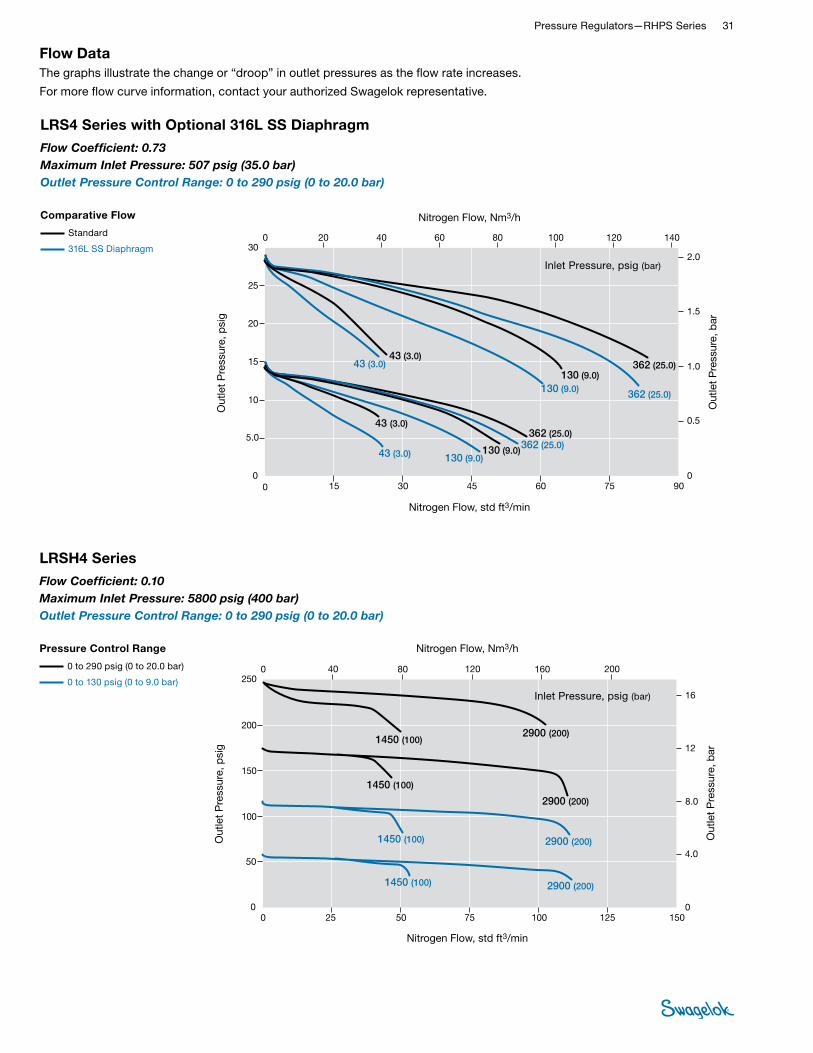
Pressure Regulators—RHPS Series 31 RHPS
REGULATORS
LRSH4 Series
Nitrogen Flow, std ft3/min
Out
let
Pre
ssur
e, p
sig
Out
let
Pre
ssur
e, b
ar
Nitrogen Flow, Nm3/h
JPN
EURO
USA
0 5025
0 40
10075 125
25 75 125
150
16012080 200
0 50 100 150
0 1000 30002000 4000
0 40 16012080 200
50
100
150
200
250
4.0
8.0
12
16
00
0
50
100
150
200
250
4,0
8,0
12
16
0
0
0.4
0.8
1.2
1.6
0
2900 (200)1450 (100)
2900 (200)
1450 (100)
2900 (200)1450 (100)
2900 (200)1450 (100)
200 (2900)100 (1450)
200 (2900)
100 (1450)
200 (2900)100 (1450)
200 (2900)100 (1450)
20.010.0
20.0
10.0
20.010.0
20.010.0
Inlet Pressure, psig (bar)
Flow DataThe graphs illustrate the change or “droop” in outlet pressures as the flow rate increases.
For more flow curve information, contact your authorized Swagelok representative.
LRS4 Series with Optional 316L SS Diaphragm
JPN
EURO
USA
0 15 604530 75 90
0 15 604530 75 90
0
5.0
10
15
20
25
30
0.5
1.0
1.5
2.0
0
0
5,0
10
15
20
25
30
0,5
1,0
1,5
2,0
0
1200400 2000
0.05
0.10
0.15
0.20
02400
0 20 6040 80 100
0 20 6040 80 100
140
140
120
120
800 1600
362 (25.0)
362 (25.0)
362 (25.0)362 (25.0)
130 (9.0)130 (9.0)
130 (9.0)130 (9.0)
43 (3.0)43 (3.0)
43 (3.0)
43 (3.0)
9,0 (103)
2.5
2.5
2.52.5
0.90.9
0.90.9
0.30.3
0.3
0.3
25,0 (362)9,0 (130)
3,0 (43) 25,0 (362)
9,0 (130)
3,0 (43)
25,0 (362)9,0 (130)
3,0 (43)25,0 (362)
3,0 (43)
0
Nitrogen Flow, std ft3/min
Out
let
Pre
ssur
e, p
sig
Out
let
Pre
ssur
e, b
ar
Nitrogen Flow, Nm3/h
Inlet Pressure, psig (bar)
Flow Coefficient: 0.10 Maximum Inlet Pressure: 5800 psig (400 bar)Outlet Pressure Control Range: 0 to 290 psig (0 to 20.0 bar)
Pressure Control Range
0 to 290 psig (0 to 20.0 bar)
0 to 130 psig (0 to 9.0 bar)
Comparative Flow
Standard
316L SS Diaphragm
Flow Coefficient: 0.73 Maximum Inlet Pressure: 507 psig (35.0 bar)Outlet Pressure Control Range: 0 to 290 psig (0 to 20.0 bar)

32 Pressure Regulators and FiltersRH
PS
REGU
LATO
RS
DimensionsDimensions, in inches (millimeters), are for reference only and are subject to change.
Ordering InformationBuild an LRS4 or LRSH4 series regulator ordering number by combining the designators in the sequence shown below.
LRS N4 - 02 - 1 - V T V - S2 41 3 5 6 7 8
Self VentingThreaded vent connection is below the panel in self-venting version.
OptionsExternal FeedbackCompensates for pressure loss (droop).
Bottom Mounting 2.28 (58.0)
6.54 (166)
2.48 (63.0)
2.95 (75.0)
2.83 (72.0)
0.75 (19.0)
0.83 (21.0) 1.42
(36.0) 1.48 (37.5)
3.52 (89.5)
Gauge connection (2)
Threaded ventconnection
Inlet Outlet
ConfigurationTop
Outlet gauge connection2.83
(72.0) 1.18 (30.0)
4 mounting holes, M6 thread, 0.39 (10.0) deep
25 µm FilterReduces potential seat damage; will reduce flow.
LRSH4 seriescartridge
LRS4 series cartridge
Outlet gauge connection
Shown with tubing for clarity; tubing not included.
Inlet OutletPanel Mounting
BAR BAR
Panel hole: 2.40 (61.0)
3.03 (77.0)
2 mounting holes for M5 × 20 screws
3 Body Material 02 = 316L SS
4 Pressure Control Range 1 = 0 to 43 psig (0 to 3.0 bar) 2 = 0 to 130 psig (0 to 9.0 bar) 3 = 0 to 290 psig (0 to 20.0 bar)
7 Seat Seal MaterialLRS series (seat seal) V = Fluorocarbon FKM N = Nitrile E = EPDM F = FFKM L = Low temperature NitrileLRSH series (seat) K = PCTFE P = PEEK
1 Series LRS = 507 psig (35 bar) maximum
inlet pressure LRSH = 5800 psig (400 bar) maximum
inlet pressure
5 Seal Material V = Fluorocarbon FKM N = Nitrile E = EPDM F = FFKM L = Low temperature Nitrile
6 Diaphragm T = PTFE➀
M = 316L SS: only for 0 to 43 psig (0 to 3.0 bar) and 0 to 130 psig (0 to 9.0 bar) pressure control ranges
L = Low temperature Nitrile➀ Not available with Low temperature Nitrile
seals.
2 Inlet / Outlet N4 = 1/2 in. female NPT
8 Options EF = External feedback F = Filter, 25 μm N = NACE MR0175/ISO 15156 S = Self venting G93 = ASTM G93 Level C-cleaned

Pressure Regulators—RHPS Series 33 RHPS
REGULATORS
Features■Balanced poppet design
■Diaphragm sensing
■Large diaphragm for higher accuracy
■Suction tube for reduced droop
■Ideal as second-stage regulator
Materials of Construction
High Sensitivity, Spring-Loaded Pressure-Reducing Regulators— LPRS4, LPRS6, and LPRS8 Series
Technical Data
Series
Maximum Inlet
Pressurepsig (bar)
Maximum Outlet Control
Pressurepsig (bar)
Sensing Type
Temperature Range °F (°C)
Flow Coefficient
(Cv)
Seat Diameterin. (mm)
Connections
Weight
Inlet and Outlet
GaugeSize Type
LPRS4
232 (16.0)
43.0 (3.0)
Diaphragm
–49 to 176 (–45 to 80)
See Pressure-Temperature
Ratings, page 887.
1.84
0.39 (10.0)
1/2 in. DN15
NPT
ISO/BSP parallel thread
ASME or EN flange
1/4 in. NPTSee
Dimensions, page 36.
LPRS6 1.95 3/4 in. DN20
LPRS8 2.07 1 in. DN25
Options■Antitamper
■Gauge connections—choice of 4 configurations
■NACE MR0175/ISO 15156-compliant models
■Special cleaning to ASTM G93 Level C
Component Material / Specification
1 Spring housing assembly 316L SS / A479
2 Ball Commercial stainless steel
3 Spring guide 316L SS / A479
4 Set spring 50CRV4
5 Nut A2
6 Washer A4
7 Cap screw A4-80
8 Washer A4
9 Nut A4-80
10 Body
316L SS / A47911 Seat
12 Poppet housing
13 Poppet spring 302 SS / A313
14 Body plug 316L SS / A479
15 Knob assembly with adjusting screw, nuts Red ABS with A2-70
16 Antitamper assembly with O-ring, adjusting screw 316L SS, nitrile, A2-70
17 Diaphragm plate 316L SS / A479
18 Diaphragm PTFE, EPDM, FKM, or nitrile
19 Diaphragm screw316L SS / A479
20 Poppet
21 O-ringsEPDM, FKM, or nitrile
22 Seat seal
23 Backup ring PTFE
Wetted lubricants: Silicone-based, synthetic hydrocarbon-based
1
2
3
4
5
67
12
109
8
21
11
15
16
17
1314
1819202122
2321
Antitamper Option LPRS Series Regulator
with Standard Knob
Wetted components listed in italics. Gauge plugs (not shown): 431 SS / A276.
See pages 34 to 35 for flow data.

34 Pressure Regulators and FiltersRH
PS
REGU
LATO
RS
LPRS4 Series
0
20
30
40
50
10
0 30 9060 120 150
0 30 9060 120 150
0 40 80 120 160 200
2.4
3.0
0.6
1.8
0
1.2
3.0
0.6
2.4
1.8
0
1.2
0
20
30
40
50
10
0 40 80 120 160 200
0.30
0.06
0.24
0.18
0
0.12
0 40 80 120 160 200
Nitrogen Flow, std ft3/min
Out
let
Pre
ssur
e, p
sig
Out
let
Pre
ssur
e, b
arO
utle
t P
ress
ure,
psi
g
Out
let
Pre
ssur
e, b
arO
utle
t P
ress
ure,
MP
a
Nitrogen Flow, std ft3/min
Nitrogen Flow, Nm3/h
Nitrogen Flow, Nm3/h
Nitrogen Flow, Nm3/h
101 (7.0), 218 (15.0)
43 (3.0), 101 (7.0), 218 (15.0)
7.0 (101), 15.0 (218)
3.0 (43), 7.0 (101), 15.0 (218)
0.7, 1.5
0.3, 0.7, 1.5
Pressure Control Range
1.4 to 14.5 psig (0.10 to 1.0 bar)
4.3 to 43 psig (0.30 to 3.0 bar)
LPRS4 Series
USA
EURO
JPN
Flow Coef�cient: 1.84Maximum Inlet Pressure: LPRS4—218 psig (15.0 bar)Outlet Pressure Control Range: 1.4 to 43 psig (0.10 to 3.0 bar)
Nitrogen Flow, std ft3/min
Out
let
Pre
ssur
e, p
sig
Out
let
Pre
ssur
e, b
ar
Nitrogen Flow, Nm3/h
Inlet Pressure, psig (bar)
Pressure Control Range
4.3 to 43 psig (0.30 to 3.0 bar)
1.4 to 14.5 psig (0.10 to 1.0 bar)
Flow Coefficient: 1.84Maximum Inlet Pressure: 218 psig (15.0 bar)Outlet Pressure Control Range: 1.4 to 43 psig (0.10 to 3.0 bar)
Flow DataThe graphs illustrate the change or “droop” in outlet pressures as the flow rate increases.
For more flow curve information, contact your authorized Swagelok representative.

Pressure Regulators—RHPS Series 35 RHPS
REGULATORS
LPRS8 Series
0
20
30
40
50
10
0 50 150100 200 300
0 50 150100 200 300
0 70 140 280 350 420
2.4
3.0
0.6
1.8
0
1.2
3.0
0.6
2.4
1.8
0
1.2
0
20
30
40
50
10
0 70 140 210 280 350
250
210
420
250
0.30
0.06
0.24
0.18
0
0.12
0 70 140 210 280 350 420
Nitrogen Flow, std ft3/min
Out
let
Pre
ssur
e, p
sig
Out
let
Pre
ssur
e, b
arO
utle
t P
ress
ure,
psi
g
Out
let
Pre
ssur
e, b
arO
utle
t P
ress
ure,
MP
a
Nitrogen Flow, std ft3/min
Nitrogen Flow, Nm3/h
Nitrogen Flow, Nm3/h
Nitrogen Flow, Nm3/h
218 (15.0)43 (3.0) 101 (7.0)
Pressure Control Range
1.4 to 14.5 psig (0.1 to 1.0 bar)
4.3 to 43 psig (0.3 to 3.0 bar)
LPRS8 Series
USA
EURO
JPN
Flow Coef�cient: 2.07Maximum Inlet Pressure: LPRS8—218 psig (15.0 bar)Outlet Pressure Control Range: 1.4 to 43 psig (0.1 to 1.0 bar)
101 (7.0)218 (15.0)
15.0 (218)3.0 (43) 7.0 (101)
7.0 (101)15.0 (218)
1.50.3 0.7
0.71.5
Nitrogen Flow, std ft3/min
Out
let
Pre
ssur
e, p
sig
Out
let
Pre
ssur
e, b
ar
Nitrogen Flow, Nm3/h
Inlet Pressure, psig (bar)
Pressure Control Range
4.3 to 43 psig (0.30 to 3.0 bar)
1.4 to 14.5 psig (0.10 to 1.0 bar)
Flow Coefficient: 2.07Maximum Inlet Pressure: 218 psig (15.0 bar)Outlet Pressure Control Range: 1.4 to 43 psig (0.10 to 3.0 bar)
Flow DataThe graphs illustrate the change or “droop” in outlet pressures as the flow rate increases.
For more flow curve information, contact your authorized Swagelok representative.

36 Pressure Regulators and FiltersRH
PS
REGU
LATO
RS
DimensionsDimensions, in inches (millimeters), are for reference only and are subject to change.
SeriesEnd Connection Size and Type
Dimensions, in. (mm) Weightlb (kg)A B C D
LPRS4
1/2 in. NPT or ISO/BSP parallel thread
10.2 (258)
2.83 (72.0)
3.07 (78.0) 2.09 (53.0)
11.0 (5.0)
DN15 PN40—EN 1092 10.2 (260)14.3 (6.5)
1/2 in. ASME class 150—B16.5 11.0 (280)
LPRS6
3/4 in. NPT or ISO/BSP parallel thread 3.23 (82.0)
3.50 (89.0) 2.20 (56.0)
12.1 (5.5)
DN20 PN40—EN 1092 10.2 (260)17.6 (7.8)
3/4 in. ASME class 150—B16.5 11.2 (285)
LPRS8
1 in. NPT or ISO/BSP parallel thread 3.07 (78.0)
3.50 (89.0) 2.20 (56.0)
12.1 (5.5)
DN25 PN40—EN 1092 10.2 (260)18.3 (8.3)
1 in. ASME class 150—B16.5 11.5 (291)
Regulators with Pipe Connections
Regulators with Flange Connections
B
B C
D
A
3.80 (97.0)
2.80(70.0)
Gauge connection
GaugesDue to the size of the diaphragm enclosure it is not possible to fit a gauge without an adapter, unless a gauge with 40 mm (1 1/2 in.) dial and center-back mount is used.
RHPS Gauge Adapter
40 mm (1 1/2 in.) gauge dial size with center-
back mount
63 mm (2 1/2 in.) or larger gauge dial size requires the
use of an adapter.
1.50 (40.0)
2.50 (63.0)
adapter
Standard Configuration Top
Inlet Outlet
Outlet gauge connection
Shown with tubing for clarity; tubing not included.
7.20 (183)
InletOutlet

Pressure Regulators—RHPS Series 37 RHPS
REGULATORS
Flow Table1/2 in. DN15, 3/4 in. DN20, 1 in. DN25 Connections
Inlet Pressure
P1psig (bar)
Set Pressure P2
psig (bar)
Pressure Control Range
psig (bar)
Flowstd ft3/min
(Nm3/h)
14.5 (1.0)
1.4 (0.10) 1.4 to 14.5 (0.10 to 1.0)
12.9 (22)
4.3 (0.30) 17.6 (30)
43 (3.0)
1.4 (0.10)1.4 to 14.5 (0.10 to 1.0)
12.9 (22)
4.3 (0.30) 23.5 (40)
11 (0.80) 35.3 (60)
29 (2.0)4.3 to 43
(0.30 to 3.0)47.0 (80)➀
72 (5.0)
1.4 (0.10)1.4 to 14.5 (0.10 to 1.0)
12.9 (22)
4.3 (0.30) 23.5 (40)
11 (0.80) 35.3 (60)
29 (2.0)4.3 to 43
(0.30 to 3.0)76.5 (130)➀
145 (10.0)
4.3 (0.30) 1.4 to 14.5 (0.10 to 1.0)
23.5 (40)
11 (0.80) 35.3 (60)
29 (2.0)4.3 to 43
(0.30 to 3.0)76.5 (130)➀
232 (16.0)
4.3 (0.30) 1.4 to 14.5 (0.10 to 1.0)
23.5 (40)
11 (0.80) 35.3 (60)
29 (2.0)4.3 to 43
(0.30 to 3.0)76.5 (130)➀
Droop
Due to the working of the suction tube, LPRS series regulators show little or no droop.
Flow
If the flows given in the table are exceeded, the set pressure P2 may rise above the original setting.
➀Droop is approximately 15 %.
Typical 2-Stage Reduction for improved set-pressure control
2900 psig (200 bar)
217 psig (15.0 bar)
14 psig (1.0 bar)
Ordering InformationBuild an LPRS4, LPRS6, and LPRS8 series regulator ordering number by combining the designators in the sequence shown below.
6 Body Material 02 = 316L SS
7 Pressure Control Range 2 = 1.4 to 14.5 psig (0.10 to 1.0 bar) 3 = 4.3 to 43 psig (0.30 to 3.0 bar)
10 Seat Seal Material V = Fluorocarbon FKM N = Nitrile E = EPDM L = Low temperature Nitrile
1 Series LPRS = 232 psig (16.0 bar)
maximum inlet pressure
8 Seal Material V = Fluorocarbon FKM N = Nitrile E = EPDM L = Low temperature Nitrile
9 Diaphragm V = Fluorocarbon FKM N = Nitrile E = EPDM L = Low temperature Nitrile
5 Flange Facing Omit designator if flanges are not ordered.
1 = Raised face smooth
LPRS FA 4 A 1 - 02 - 2 - V V V - GN22 41 3 5 6 7 8 9 10 11
2 Inlet / Outlet B = Female ISO/BSP parallel thread N = Female NPT FA = ASME B16.5 flange FD = EN 1092 (DIN) flange
11 Options A = Antitamper GN2 = Gauge connection, see below GN4 = Gauge connection, see below GN5 = Gauge connection, see belowNone = Standard connection, see below
Gauge Connection Configuration
Standard GN2 GN4 GN5
Go GiGoGo Gi Go
Gi Gi GoGi Gi Go
Gi Go GiGi Gi Go
std
Pressure reducing
Back Pressure
std
N = NACE MR0175/ISO 15156 G93 = ASTM G93 Level C-cleaned
4 Pressure Class Omit designator if flanges are not ordered.
A = ASME class 150 N = EN class PN40
3 Size 4 = 1/2 in. / DN15 6 = 3/4 in. / DN20 8 = 1 in. / DN25

38 Pressure Regulators and FiltersRH
PS
REGU
LATO
RS
Features■Balanced poppet design
■Diaphragm sensing
■High flow and high accuracy
■Suction tube for reduced droop
■Ideal as second-stage regulator
Materials of Construction
High-Sensitivity, Spring-Loaded Pressure-Reducing Regulators— LPRS10 and LPRS15 Series
Options■Antitamper
■NACE MR0175/ISO 15156-compliant models
■Special cleaning to ASTM G93 Level C
Technical Data
Series
Maximum Inlet
Pressurepsig (bar)
Maximum Outlet Control
Pressurepsig (bar)
Sensing Type
Temperature Range °C (°F)
Flow Coefficient
(Cv)
Seat Diameterin. (mm)
Connections Weight(Without Flanges)
lb (kg)
Inlet and Outlet
GaugeSize Type
LPRS10
232 (16.0)
43.0 (3.0)
Diaphragm
–49 to 176 (–45 to 80)
See Pressure-Temperature
Ratings, page 887.
3.79 0.55 (14.0)1 in.
DN25
NPT
ISO/BSP parallel thread
ASME or EN flange
1/4 in. NPT or
ISO/BSP parallel thread➀
17.6 (8.0)
LPRS15 7.30 0.75 (19.0)1 1/2 in.
DN4022.0 (10.0)
Component Material / Specification
1 Adjusting screw A2-70
2 Nut A2
3 Ball Commercial stainless steel
4 Spring guide 316L SS / A479
5 Set spring 50CRV4
6 Spring housing assembly 316L SS / A479
7 Nut A2
8 Washer A4
9 Diaphragm plate 316L SS / A479
10 Cap screw A4-80
11 Washer A2
12 Nut A2
13 Diaphragm PTFE, FKM, EPDM, or nitrile
14 Diaphragm screw316L SS / A479
15 Bottom cover
16 Retaining ring Commercial stainless steel
17 Body plate 316L SS / A479
18 O-ringsEPDM, FKM, or nitrile
19 Seat seal
20 Suction tube
316L SS / A479
21 Poppet
22 Seat
23 Poppet housing
24 Body
25 Poppet spring 302 SS / A313
26 Body plug 316L SS / A479
27 Backup ring PTFE
Wetted lubricant: Silicone-based, synthetic hydrocarbon-based
1
2
3
45
6
17 182021
2223
7
12
109 8
11
1516
1314
18
2418
182526 27
LPRS10 Series Regulator
See page 39 for flow data.➀Regulators with NPT inlet / outlet connections have 1/4 in. NPT gauge connections.
19
Wetted components listed in italics. Gauge plugs (not shown): 431 SS / A276.

Pressure Regulators—RHPS Series 39 RHPS
REGULATORS
LPRS15 Series
Flow DataThe graphs illustrate the change or “droop” in outlet pressures as the flow rate increases.
For more flow curve information, contact your authorized Swagelok representative.
JPN
EURO
USA
0 200 600400 800
0 1000
0.5
0
50
1,5
0
1000
3000 12 0006000 15 0000
18 000
200 300 400 500 600 700
0 100 200 300 400 500 600 700
0 200 600400 800 1000
10
20
30
40
50
1.0
2.0
2.5
0.0
10
20
30
40
2,0
2,5
3,0
3.0
1,0
9000
1.5
0,5
0.15
0.20
0.25
0.30
0.10
0.05
0
101 (7.0)43 (3.0)218 (15.0)
101 (7.0)43 (3.0)
218 (15.0)101 (7.0)43 (3.0)
218 (15.0)
101 (7.0)43 (3.0)
218 (15.0)
101 (7.0)
218 (15.0)
7,0 (101)3,0 (43)15,0 (218)
7,0 (101)3,0 (43)
15,0 (218)7,0 (101)3,0 (43)
15,0 (218)
7,0 (101)3,0 (43)
15,0 (218)
7,0 (101)
15,0 (218)
7.0 3.015.0
7.0 3.0
15.07.0 3.0
15.0
7.0
3.0
15.07.0
15.0
Nitrogen Flow, std ft3/min
Out
let
Pre
ssur
e, p
sig
Out
let
Pre
ssur
e, b
ar
Nitrogen Flow, Nm3/h
Inlet Pressure, psig (bar)
LPRS10 Series
JPN
EURO
USA
0 75 300225150 375 450
0 75 300225150 375 450
0
10
20
30
40
50
0.5
1.5
2.5
3.0
0.0
0
10
20
30
40
50
0,5
1,5
2,5
3,0
0
2000 80004000 10 000 12 000
0 100 300200 500 600
0 100 300200 500 600
400 700
1.0
2.0
400 700
1,0
2,0
0.05
0.15
0.25
0.30
0.10
0.20
00 6000
101 (7.0)
101 (7.0)
43 (3.0)
43 (3.0)218 (15.0)
7,0 (101)3,0 (43) 15,0 (218)
7.0 3.0 15.0
7.0 3.0 15.0
7.0 3.0 15.0
7.0 3.0
15.0
7.0 15.0
7,0 (101)3,0 (43) 15,0 (218)
7,0 (101)3,0 (43) 15,0 (218)
7,0 (101)3,0 (43)
15,0 (218)
7,0 (101) 15,0 (218)
218 (15.0)
101 (7.0)43 (3.0) 218 (15.0)
101 (7.0)43 (3.0)
218 (15.0)
101 (7.0)218 (15.0)
Nitrogen Flow, std ft3/min
Out
let
Pre
ssur
e, p
sig
Out
let
Pre
ssur
e, b
ar
Nitrogen Flow, Nm3/h
Inlet Pressure, psig (bar)
Flow Coefficient: 7.3 Maximum Inlet Pressure: 232 psig (16.0 bar)Outlet Pressure Control Range: 1.4 to 43 psig (0.10 to 3.0 bar)
Pressure Control Range
4.3 to 43 psig (0.30 to 3.0 bar)
1.4 to 14.0 psig (0.10 to 1.0 bar)
Flow Coefficient: 3.79 Maximum Inlet Pressure: 232 psig (16.0 bar)Outlet Pressure Control Range: 1.4 to 43 psig (0.10 to 3.0 bar)
Pressure Control Range
4.3 to 43 psig (0.30 to 3.0 bar)
1.4 to 14.0 psig (0.10 to 1.0 bar)

40 Pressure Regulators and FiltersRH
PS
REGU
LATO
RS
DimensionsDimensions, in inches (millimeters), are for reference only and are subject to change.
Regulators with Pipe Connections Regulators with Flange Connections
SeriesEnd Connection Size and Type
Dimensions, in. (mm)
A B C D E F
LPRS10
1 in. NPT or ISO/BSP parallel thread
10.8 (275)
3.54 (90.0)
3.07 (78.0) 2.28 (58.0) 4.69 (119)2.00 (50.8)
DN25 PN40—EN 1092 9.69 (246)
1 in. ASME class 150—B16.5 9.65 (245)
LPRS15
1 1/2 in. NPT or ISO/BSP parallel thread
11.3 (286)
4.53 (115)
3.78 (96.0) 2.44 (62.0) 5.12 (130)2.03 (51.6)
DN40 PN40—EN 1092 11.0 (280)
1 1/2 in. ASME class 150—B16.5 12.4 (314)
B C
D
E
Configuration Top
Inlet Outlet
Inlet gaugeconnection
A
1.96(50.0)
7.20(183)
Outlet gauge connection
F
B
Shown with tubing for clarity; tubing not included.
1.38 (35.1) 1.77
(45.0)
InletOutlet
Only one gauge with a 50 mm (2 in.) or larger
dial size fits directly into the body.
Gauge Connection

Pressure Regulators—RHPS Series 41 RHPS
REGULATORS
Ordering InformationBuild an LPRS10 and LPRS15 series regulator ordering number by combining the designators in the sequence shown below.
6 Body Material 02 = 316L SS
7 Pressure Control Range 2 = 1.4 to 14.5 psig (0.10 to 1.0 bar) 3 = 4.3 to 43 psig (0.30 to 3.0 bar)
10 Seat Seal Material V = Fluorocarbon FKM N = Nitrile E = EPDM L = Low temperature Nitrile
1 Series LPRS = 232 psig (16.0 bar) maximum
inlet pressure
8 Seal Material V = Fluorocarbon FKM N = Nitrile E = EPDM L = Low temperature Nitrile
9 Diaphragm V = Fluorocarbon FKM N = Nitrile E = EPDM L = Low temperature Nitrile
5 Flange Facing Omit designator if flanges are not ordered.
1 = Raised face smooth
LPRS FA 10 A 1 - 02 - 2 - V V V - G932 41 3 5 6 7 8 9 10 11
2 Inlet / Outlet B = Female ISO/BSP parallel thread N = Female NPT FA = ASME B16.5 flange FD = EN 1092 (DIN) flange
11 Options A = Antitamper N = NACE MR0175/ISO 15156 G93 = ASTM G93 Level C-cleaned
4 Pressure Class Omit designator if flanges are not ordered.
A = ASME class 150 N = EN class PN40
3 Size 10 = 1 in. / DN25 15 = 1 1/2 in. / DN40

42 Pressure Regulators and FiltersRH
PS
REGU
LATO
RS
Pressure-Reducing Regulators Spring-Loaded—RS Series Maintenance Kits
Designator Kit Type Diaphragm Sensing Typical Contents Piston Sensing Typical Contents
A1 Valve kit Poppet and housing (9, 21, 22), O-rings (10a, 10b), Back-up ring (11a), Seat (20)
Poppet (9), O-rings (10a, 10b), Back-up rings (11a), Seat (23), Seat seal (24)
A2 Soft valve kit Poppet and housing (9, 21 22), O-ring (10b), Back-up ring (11a) O-ring (10a), Seat (23), Seat seal (24)
B1 Service kit Poppet and housing (9, 21, 22), O-rings (10a, 10b, 10c), Back-up ring (11a), Diaphragm (16), Seat (20)
Poppet (9), O-rings (10a, 10b, 10c, 10d, 10e), Back-up rings (11a, 11b, 11c), Seat (23), Seat seal (24)
B2 Seal kit O-rings (10a, 10b, 10c), Back-up ring (11a), Diaphragm (16)
O-rings (10a, 10b, 10c, 10d, 10e), Back-up rings (11a, 11b, 11c)
C1 Overhaul kit
Spring guides (2, 7), Ball (3), Set spring (4), Poppet and housing (9, 21, 22), O-rings (10a, 10b, 10c), Back-up ring (11a), Poppet spring (12), Body plug (13), Diaphragm (16), Diaphragm plate (17), Seat (20)
Spring guide (2), Ball (3), Set spring (4), Poppet (9), O-rings (10a, 10b, 10c, 10d, 10e), Back-up rings (11a, 11b, 11c), Poppet spring (12), Body plug (13), Piston (18), Piston plate (19), Seat (23), Seat seal (24)
C2 Body plug kit O-ring (10c), Body plug (13) O-ring (10c), Body plug (13), Back-up ring (11b)
C3 Sensing kit Diaphragm (16) Piston (18), Piston plate (19), O-rings (10d, 10e), Back-up ring (11c)
C4 Range spring kit Range spring (4) Range spring (4)
C5 Poppet spring kit Poppet spring (12) Poppet spring (12)
D1 Handle kit Handle assembly (14) Handle assembly (14)
E1 Hardware kit Bolts (5), Washers (6) Bolts (5), Washers (6)
Regular maintenance of pressure regulator components is an important part of keeping pressure regulators operating successfully. Swagelok offers several maintenance kit options to help keep components and systems performing well. Outlined below are the standard maintenance kit offerings and an example of which parts are included in each kit. For more detailed information of which parts will be included within a kit for a specific regulator model, please reference the appropriate owner’s manual or contact your authorized Swagelok Sales and Service center.
Ordering InformationTo order a maintenance kit, add the kit type designator to the regulator ordering number. Example: RSN4-02-1-VVV-B1
13
11b
10c
12
11a
10b
9,21,22
20,23,24
10a
8
16
7
17
10d
19
10e
11c
18
14
15
6
5
3
1
2
4
1
14
234
56716
17
20
9
2122
10b11a10c1213
8
15
18
11c19
10e
23
24
11b
10a
10d

Pressure Regulators—RHPS Series 43 RHPS
REGULATORS
These pressure-reducing, dome-loaded and air-loaded regulators are suitable for most gases and liquids, including acids and oils. These regulators feature various poppet designs, a pressure-sensing diaphragm (piston in RD2 series), and a choice of seat and seal materials to accommodate a variety of pressure, temperature, and flow conditions.
These regulators are available with a choice of threaded end connections from 1/4 to 2 in., and with flange end connections from 1/2 to 4 in.
The RDH series regulators are high-pressure versions of the RD series regulators, and the LPRD series are low-pressure, high-accuracy versions of the RD series regulators. The RA series regulators are air-loaded regulators.
These regulators are available with many options, including a variety of gauge connection configurations, a pilot regulator (RD series only), external feedback (RD series only), special cleaning to ASTM G93 Level C, and NACE MR0175/ISO 15156-compliant models.
Pressure-Reducing, Dome-Loaded and Air-Loaded Regulators—RD and RA Series
Features■Dome-loaded and air-loaded pressure control
■Diaphragm sensing design except RD2 series
■316L stainless steel materials of construction for corrosion resistance
■Maximum inlet pressure ratings: 1015 to 5800 psig (70.0 to 400 bar)
■Outlet pressure control ranges: Up to 0 to 5800 psig (0 to 400 bar)
RD2
RD(H)6, 8
RD(H)6DP
RD(H)20, 25
RD(H)30, 40
LPRD25, 30, 40
RA4, 6, 8
RD(H)10, 15

44 Pressure Regulators and FiltersRH
PS
REGU
LATO
RS
Technical Data—Performance
Series
Maximum Inlet Pressure➀
psig (bar)
Maximum Outlet Control Pressure➀
psig (bar)
Flow Coefficient
(Cv )Sensing
Type
Flow Data
on Page
RD2 5800 (400) 5800 (400) 0.05 Piston 47
RD6DP 1015 (70.0) 1015 (70.0)1.95 Diaphragm —
RDH6DP 5800 (400) 3335 (230)
RD6 1015 (70.0) 1015 (70.0)1.95 Diaphragm 51
RDH6 5800 (400) 5800 (400)
RD8 1015 (70.0) 1015 (70.0)2.07 Diaphragm —
RDH8 5800 (400) 5800 (400)
RD10 1015 (70.0) 1015 (70.0)3.79 Diaphragm 61
RDH10 5800 (400) 3625 (250)
RD15 1015 (70.0) 1015 (70.0)7.30 Diaphragm 66,
70RDH15 5800 (400) 3625 (250)
RD20 1015 (70.0) 1015 (70.0)13 Diaphragm 73,
74RDH20 5800 (400) 2900 (200)
RD25 1015 (70.0) 1015 (70.0)21 Diaphragm —
RDH25 4060 (280) 2900 (200)
RD30 1015 (70.0) 1015 (70.0)36 Diaphragm —
RDH30 4060 (280) 2900 (200)
RD40 1015 (70.0) 1015 (70.0)73 Diaphragm —
RDH40 4060 (280) 2900 (200)
LPRD20
232 (16.0) 29 (2.0)
13
Diaphragm —LPRD25 21
LPRD30 36
LPRD40 73
RA4
5800 (400) 5800 (400) 1.84 Diaphragm —RA6
RA8
➀ Regulator pressure rating may be limited by connection type.
Pressure-Temperature Ratings
Seal Material Temperature Range
°F (°C) Material
Designator
Fluorocarbon FKM 5 to 176 (–15 to 80) V
Standard Nitrile -4 to 176 (–20 to 80) N
Low-Temp Nitrile -49 to 176 (–45 to 80) L
EPDM -4 to 176 (–20 to 80) E
FFKM 14 to 176 (–10 to 80) F
Seat Material PCTFE PEEKFluorocarbon FKM,
Nitrile, EPDM, FFKM
Temperature °F (°C)
Maximum Inlet Pressure / Working Pressure psig (bar)
-49 to -40 (–45 to -40) – –
1015 (70.0)-40 to 95 (–40 to 35) 5 800 (400)
5 800 (400)149 (65) 3987 (275)
176 (80) 1812 (125)
Pressure-Reducing, Dome-Loaded and Air-Loaded Regulators—RD and RA Series

Pressure Regulators—RHPS Series 45 RHPS
REGULATORS
Dome-loading mechanism
Inlet Outlet
Diaphragm sensing mechanism
Pressure-Reducing, Dome-Loaded and Air-Loaded Regulators—RD and RA SeriesRD Series Pressure-Reducing,
Dome-Loaded Regulator
Hard seat seal design for high-pressure
applications
Technical Data—Design
Series
Seat Diameter in. (mm) Inlet and Outlet Connections Gauge Connection Dome Connection
Weight (Without Flanges)
lb (kg)
More Information
on Page
RD2 0.087 (2.2) 1/4 in. NPT 1/4 in. NPT 1/8 in. NPT 3.1 (1.4) 46
RD6DP 0.39 (10.0)
3/4 in. NPT, ISO/BSP parallel thread, EN or ASME flanges 1/4 in. NPT 1/4 in. NPT 10.6 (4.8) 55
RDH6DP
RD6 0.39 (10.0)
3/4 in. NPT, ISO/BSP parallel thread, EN or ASME flanges 1/4 in. NPT 1/4 in. ISO/BSP
parallel thread 8.8 (4.0) 50RDH6
RD8 0.39 (10.0)
1 in. NPT, ISO/BSP parallel thread, EN or ASME flanges 1/4 in. NPT 1/4 in. ISO/BSP
parallel thread 8.8 (4.0) 50RDH8
RD10 0.55 (14.0) 1 in. NPT, ISO/BSP parallel thread, EN or ASME flanges
1/4 in. NPT or ISO/BSP parallel thread
1/4 in. ISO/BSP parallel thread 17.6 (6.0) 59
RDH10 0.53 (13.5)
RD15 0.75 (19.0)
1 1/2 in. NPT, ISO/BSP parallel thread, EN or ASME flanges
1/4 in. NPT or ISO/BSP parallel thread
1/4 in. ISO/BSP parallel thread 19.8 (9.0) 59
RDH15
RD20 0.98 (25.0)
2 in. NPT, ISO/BSP parallel thread, EN or ASME flanges
Use P1 gauge connections on pilot regulator
1/4 in. ISO/BSP parallel thread 44.0 (20) 72
RDH20
RD25 1.25 (32.0) 2 1/2 in. EN or ASME flanges Use P1 gauge connections
on pilot regulator1/4 in. ISO/BSP parallel thread 88.0 (40) 72
RDH25
RD30 1.65 (42.0) 3 in. EN or ASME flanges Use P1 gauge connections
on pilot regulator1/4 in. ISO/BSP parallel thread 136 (62) 84
RDH30
RD40 2.36 (60.0) 4 in. EN or ASME flanges Use P1 gauge connections
on pilot regulator1/4 in. ISO/BSP parallel thread 183 (83) 84
RDH40
LPRD20 0.98 (25.0) 2 in. EN or ASME flanges
Inlet and outlet gauges included
1/4 in. ISO/BSP parallel thread
Varies with model
and end connection
99
LPRD25 1.25 (32.0) 2 1/2 in. EN or ASME flanges 99
LPRD30 1.65 (42.0) 3 in. EN or ASME flanges 99
LPRD40 2.36 (60.0) 4 in. EN or ASME flanges 99
RA4
0.39 (10.0)
1/2 in. NPT, ISO/BSP parallel thread, EN or ASME flanges
1/4 in. NPT 1/4 in. ISO/BSP parallel thread
12.5 (5.7)
101RA6 3/4 in. NPT, ISO/BSP parallel thread, EN or ASME flanges 13.6 (6.2)
RA8 1 in. ISO/BSP parallel thread, EN or ASME flanges 13.6 (6.2)
Soft seat seal design for low-pressure
applications

46 Pressure Regulators and FiltersRH
PS
REGU
LATO
RS
Features■Piston sensing
■Integral 25 μm filter
■Cartridge poppet assembly for ease of service
■Bottom mounting
Compact, General-Purpose Dome-Loaded Pressure-Reducing Regulators—RD2 Series
Options■No filter—for liquid applications
■NACE MR0175/ISO 15156-compliant models (nonventing and no-filter models only)
■Special cleaning to ASTM G93 Level C
■Panel mounting kit sold separately— no disassembly required
Technical Data
Series
Maximum Inlet
Pressurepsig (bar)
MaximumOutlet Control
Pressurepsig (bar)
Sensing Type
Temperature Range °F (°C)
Flow Coefficient
(Cv)
Seat Diameterin. (mm)
Inlet and Outlet
Connections
Gauge / Dome
ConnectionWeightlb (kg)
RD2 5800 (400)
5800 (400)
Piston
–40 to 95 (–40 to 35)
See Pressure-Temperature
Ratings, page 921.
0.05 0.087 (2.2)
1/4 in. NPT
Gauge: 1/4 in. NPT
Dome: 1/8 in. NPT
3.1 (1.4)
Materials of Construction
Component Material / Specification
1 Dome plug316L SS / A479
2 Dome
3 Dome plug O-ring FKM, EPDM, nitrile, or FFKM
4 Non-relieving plug
316L SS / A4795 Piston
6 Piston plate
7 Piston O-rings FKM, EPDM, nitrile, or FFKM
8 Poppet 431 SS / A276
9 Poppet housing 316L SS / A479
10 O-rings FKM, EPDM, nitrile, or FFKM
11 Seat PEEK or PCFTE
12 Seat retainer 316L SS / A479
13 Poppet spring 302 SS / A313
14 Filter 316L SS
15 Plug316L SS / A479
16 Body
Wetted lubricants: Silicone-based and synthetic hydrocarbon-based
2
3
4
5
6
7
1
10
11
12
13
14
9
8
15
10
7
16
Wetted components listed in italics. Gauge plugs (not shown): 431 SS / A276.
See page 47 to 48 for flow data.

Pressure Regulators—RHPS Series 47 RHPS
REGULATORS
Flow DataThe graphs illustrate the change or “droop” in outlet pressures as the flow rate increases.
For more flow curve information, contact your authorized Swagelok representative.
0
150
200
250
300
350
400
25
JPN
EURO
USA
100
50
20
5.0
10
15
0
150
200
250
300
350
400
25
100
50
20
5,0
10
15
0
0 40
0 50
16012080 200
200150100 250
0 40 16012080 200
0
2.5
2.0
0.5
1.0
1.5
0 1000 400030002000 5000
0
300
50 200150100 250 300
580 (40.0) 1015 (70.0)
2900 (200)
5800 (400)
580 (40.0)1015 (70.0) 2900 (200)
5800 (400)
580 (40.0) 1015 (70.0)2900 (200), 5800 (400)
40,0 (580) 70,0 (1015)
200 (2900)
400 (5800)
200 (2900)400 (5800)
70,0 (1015)200 (2900), 400 (5800)
40,0 (580)
40,0 (580) 70,0 (1015)
4.0 7.0
20.0
40.0
20.0, 40.07.04.0
4.0 7.0, 20.0, 40.0
RD2 Series
Nitrogen Flow, std ft3/min
Out
let
Pre
ssur
e, p
sig
Nitrogen Flow, Nm3/h Pressure Control Range
0 to 5800 psig (0 to 400 bar)
JPN
EURO
USA
0 50 200150100 250 300
0 50 200150100 250 300
0
500
1000
1500
2000
2500
3000
50
100
150
200
0
0
500
1000
1500
2000
2500
3000
50
100
150
200
0
1500 45003000 6000
5.0
10
15
20
07500
0 75 225150 300 375
0 75 225150 300 375
450
450
5800 (400)
5800 (400)
5800 (400)2900 (200)
2900 (200)
2900 (200)
2900 (200) 5800 (400)580 (40.0)
1015 (70.0)
1015 (70.0)
40,0 (580) 70,0 (1015)
70,0 (1015) 200 (2900)
200 (2900)
200 (2900)
200 (2900)
400 (5800) 400 (5800)
400 (5800)
400 (5800)
20.0
20.0
20.0
20.0
4.040.0
40.0
40.0
40.0
7.0
7.0
RD2 Series
Pressure Control Range
0 to 5800 psig (0 to 400 bar)
Nitrogen Flow, std ft3/min
Out
let
Pre
ssur
e, p
sig
Nitrogen Flow, Nm3/h
Out
let
Pre
ssur
e, b
arO
utle
t P
ress
ure,
bar
Flow Coefficient: 0.05Maximum Inlet Pressure: 5800 psig (400 bar)Outlet Pressure Control Range: 0 to 5800 psig (0 to 400 bar)
Flow Coefficient: 0.05Maximum Inlet Pressure: 5800 psig (400 bar)Outlet Pressure Control Range: 0 to 5800 psig (0 to 400 bar)
Inlet Pressure, psig (bar)
Inlet Pressure, psig (bar)

48 Pressure Regulators and FiltersRH
PS
REGU
LATO
RS
Flow DataThe graphs illustrate the change or “droop” in outlet pressures as the flow rate increases.
For more flow curve information, contact your authorized Swagelok representative.
JPN
EURO
USA
0 50 200150100 250 300
0 50 200150100 250 300
0
1000
2000
3000
4000
5000
6000
100
200
300
400
0
0
1000
2000
3000
4000
5000
6000
100
200
300
400
0
1500 45003000 6000
10
20
30
40
07500
0 75 225150 300 375
0 75 225150 300 375
450
450
5800 (400)
5800 (400)2900 (200)
400 (5800)
400 (5800)200 (2900)
40.0
40.020.0
RD2 Series
Nitrogen Flow, std ft3/min
Out
let
Pre
ssur
e, p
sig
Nitrogen Flow, Nm3/h Pressure Control Range
0 to 5800 psig (0 to 400 bar)
Out
let
Pre
ssur
e, b
ar
Flow Coefficient: 0.05Maximum Inlet Pressure: 5800 psig (400 bar)Outlet Pressure Control Range: 0 to 5800 psig (0 to 400 bar)
Inlet Pressure, psig (bar)

Pressure Regulators—RHPS Series 49 RHPS
REGULATORS
DimensionsDimensions, in inches (millimeters), are for reference only and are subject to change.
Ordering InformationBuild an RD2 series regulator ordering number by combining the designators in the sequence shown below.
3 Body Material 02 = 316L SS
2 Inlet / Outlet N2 = 1/4 in. female NPT
6 Seat Material K = PCTFE P = PEEK
7 Options L = No filter N = NACE MR0175/ISO 15156 G93 = ASTM G93 Level C-cleaned
RD N2 - 02 - V V K - L2 41 3 5 6 7
1 Series RD = 5800 psig (400 bar) maximum
inlet pressure
4 Seal Material V = Fluorocarbon FKM N = Nitrile E = EPDM F = FFKM L = Low temperature Nitrile
5 Piston Seal Material V = Fluorocarbon FKM N = Nitrile E = EPDM F = FFKM L = Low temperature Nitrile
ConfigurationTop
Dome
Inlet Outlet
1.31 (33.3)
3.78 (96.0)
2.16 (55.0)
1.26 (32.0)
0.87 (22.0)
4.21 (107)
2.16 (55.0)
0.67 (17.0)
Outlet gaugeconnection
Inlet gaugeconnection
Shown with tubing for clarity; tubing not included.
Inlet Outlet
2 mounting holes M5, 0.20 (5.0) deep
2 gauge connections
Domeconnection
Inlet Outlet
Panel hole
2 holes, 0.22 (5.5)
Panel ring
2.76 (70.0)
3.13 (79.5)
2.36 (60.0)
2.36 (60.0) A
A
Panel Mounting Kit
No disassembly required when using panel mount kit. Panel mounting kit ordering number: RS2-P-02

50 Pressure Regulators and FiltersRH
PS
REGU
LATO
RS
Features■Balanced poppet design
■Diaphragm sensing
■Dome-to-outlet pressure ratio approximately 1:1
Materials of Construction
General-Purpose, Dome-Loaded Pressure-Reducing Regulators— RD(H)6 and RD(H)8 Series
Options■Antitamper
■Pilot regulator (not shown)■Gauge connections—choice of 4
configurations
■NACE MR0175/ISO 15156-compliant models
■Special cleaning to ASTM G93 Level C
Technical Data
Series
Maximum Inlet
Pressurepsig (bar)
Maximum Outlet Control
Pressurepsig (bar)
Sensing Type
Temperature Range °F (C°)
Flow Coefficient
(Cv)
Seat Diameterin. (mm)
Inlet and Outlet Connections
Gauge / Dome Connection
Weight (Without Flanges)
lb (kg)
RD6 RDH6 RD:
1015 (70.0)
RDH: 5800 (400)
RD: 1015 (70.0)
RDH: 5800 (400)
(2537 [175] with pilot regulator)
Diaphragm
–49 to 176 (–45 to 80)
See Pressure-Temperature
Ratings, page 921.
1.95
0.39 (10.0)
3/4 in. NPT, ISO/BSP parallel thread, EN or
ASME flange
Gauge: 1/4 in. NPT;
Dome: 1/4 in.
ISO/BSP parallel thread
8.8 (4.0)
RD8 RDH8 2.07
1 in. NPT, ISO/BSP parallel thread, EN or
ASME flange
Component Material / Specification
1 Dome 316L SS / A479
2 Cap screw A4-80
3 Washer A4
4 Dome plate 316L SS / A479
5 Diaphragm EPDM, FKM, or nitrile
6 Diaphragm plate 316L SS / A479
7 O-ring EPDM, FKM, or nitrile
8 Backup ring PTFE
9 Plug O-ring EPDM, FKM, or nitrile
10 Body 316L SS / A479
11 Poppet spring 302 SS / A313
12 Body plug 316L SS / A479
RD Series Only Components
13 Poppet316L SS / A479
14 Seat
15 Seat seal EPDM, FKM, or nitrile
16 Poppet housing 316L SS/ A479
RDH Series Only Components
17 Poppet S17400 or 431 SS / A276
18 Seat 316L SS/ A479
19 Seat seal PCTFE or PEEK
20 Backup ring PTFE
Wetted lubricants: Silicone-based and synthetic hydrocarbon-based
23
4
56
7
1
101112
13
14
9
81516
171819
20
RD6 Series Regulator with Soft Seat Seal
RDH6 Series Regulator with Hard Seat Seal
Wetted components listed in italics. Gauge plugs (not shown): 431 SS / A276.
See page 51 to 53 for flow data.

Pressure Regulators—RHPS Series 51 RHPS
REGULATORS
Flow DataThe graphs illustrate the change or “droop” in outlet pressures as the flow rate increases.
For more flow curve information, contact your authorized Swagelok representative.
RDH6 Series
Nitrogen Flow, std ft3/min
Out
let
Pre
ssur
e, p
sig
Out
let
Pre
ssur
e, b
ar
Nitrogen Flow, Nm3/h
JPN
EURO
USA
0 500 15001000 2000
0 400 1200800 1600 2000
0 400 1200800 1600 2000
2500
10 000 40 000
0
0
500 15001000 2000 3000
0
480
720
960
120080
240
60
40
0
0
480
720
960
120080
240
40
60
0
0
3000
2500
20
20
8.0
6.0
2.0
4.0
50 00030 00020 0000
580 (40.0) 1015 (70.0) 2175 (150)
580 (40.0)
1015 (70.0)
2175 (150)
1015 (70.0) 2175 (150)
2175 (150)
40,0 (580) 70,0 (1015) 150 (2175)
40,0 (580)
70,0 (1015)150 (2175)
70,0 (1015) 150 (2175)
150 (2175)
4.0 7.0 15.0
4.0 7.0
15.0
7.0 15.0
15.0
Inlet Pressure, psig (bar)
Flow Coefficient: 1.95Maximum Inlet Pressure: 5800 psig (400 bar)Outlet Pressure Control Range: 0 to 1450 psig (0 to 100 bar)
Pressure Control Range
0 to 1450 psig (0 to 100 bar)
0 to 362 psig (0 to 25.0 bar)
RDH6 Series
JPN
EURO
USA
0 180 540360 720 900
0 180 540360 720 900
0
50
100
150
200
250
300
5.0
10
15
20
0
0
50
100
150
200
250
300
5,0
10
15
20
0
80004000 12 000
0.5
1.0
1.5
2.0
020 000
0 200 600400 1000800 1200
0 200 600400 800 1000
16 000
1400
1200 1400
24 000
218 (15.0), 580 (40.0)1015 (70.0), 2175 (150)
218 (15.0)580 (40.0), 1015 (70.0)
2175 (150)
218 (15.0)580 (40.0)
1015 (70.0)2175 (150)
580 (40.0) 1015 (70.0)
2175 (150)218 (15.0)
15,0 (218), 40,0 (580)70,0 (1015), 150 (2175)
15,0 (218)40,0 (580), 70,0 (1015)
150 (2175)
40,0 (580) 70,0 (1015)150 (2175)
40,0 (580) 70,0 (1015)
150 (2175)15,0 (218)
15,0 (218)
1.5, 4.0 7.0 , 15.0
1.5 4.0, 7.015.0
4.0 7.0 15.0
4.0 7.0
15.0
1.5
1.5
4.0, 7.015.0
Nitrogen Flow, std ft3/min
Out
let
Pre
ssur
e, p
sig
Out
let
Pre
ssur
e, b
ar
Nitrogen Flow, Nm3/h
Inlet Pressure, psig (bar)
Flow Coefficient: 1.95Maximum Inlet Pressure: 5800 psig (400 bar)Outlet Pressure Control Range: 0 to 362 psig (0 to 25.0 bar)
Pressure Control Range
0 to 362 psig (0 to 25.0 bar)
0 to 145 psig (0 to 10.0 bar)

52 Pressure Regulators and FiltersRH
PS
REGU
LATO
RS
RDH6 Series
Nitrogen Flow, std ft3/min
Out
let
Pre
ssur
e, p
sig
Out
let
Pre
ssur
e, b
ar
Nitrogen Flow, Nm3/h
0
1000
1500
2000
2500
3000
500
0 1000 30002000 4000 5000
0 1000 30002000 4000 5000
0 1500 3000 4500 6000 7500
120
150
180
30
90
0
60
180
150
30
120
90
0
60
0
1000
1500
2000
2500
3000
500
0 1500 3000 4500 6000 7500
18.0
15.0
3.0
12.0
9.0
0
6.0
0 1500 3000 4500 6000 7500
Nitrogen Flow, std ft3/min
Out
let
Pre
ssur
e, p
sig
Out
let
Pre
ssur
e, b
arO
utle
t P
ress
ure,
psi
g
Out
let
Pre
ssur
e, b
arO
utle
t P
ress
ure,
MP
a
Nitrogen Flow, std ft3/min
Nitrogen Flow, Nm3/h
Nitrogen Flow, Nm3/h
Nitrogen Flow, Nm3/h
2900 (200)
3990 (275)
200 (2900)
275 (3990)
20.0
27.5
Pressure Control Range
0 to 2539 psig (0 to 175 bar)
RDH6 Series
USA
EURO
JPN
Flow Coef�cient: 1.95Maximum Inlet Pressure: RDH6—3990 psig (275 bar)Outlet Pressure Control Range: 0 to 2539 psig (0 to 175 bar)
Inlet Pressure, psig (bar)
Flow Coefficient: 1.95Maximum Inlet Pressure: 3990 psig (275 bar)Outlet Pressure Control Range: 0 to 2537 psig (0 to 175 bar)
Pressure Control Range
0 to 2537 psig (0 to 175 bar)
Flow DataThe graphs illustrate the change or “droop” in outlet pressures as the flow rate increases.
For more flow curve information, contact your authorized Swagelok representative.
RD8 Series
Nitrogen Flow, std ft3/min
Out
let
Pre
ssur
e, p
sig
Out
let
Pre
ssur
e, b
ar
Nitrogen Flow, Nm3/h
0
400
600
800
1000
1200
200
0 500 15001000 2000 3000
0 500 15001000 2000 3000
0 750 1500 2250 3000 4500
52
65
78
13
39
0
26
78
65
13
52
39
0
26
0
400
600
800
1000
1200
200
0 750 1500 2250 3000 4500
2500
3750
3750
2500
7.8
6.5
1.3
5.2
3.9
0
2.6
0 750 1500 2250 3000 45003750
Nitrogen Flow, std ft3/min
Out
let
Pre
ssur
e, p
sig
Out
let
Pre
ssur
e, b
arO
utle
t P
ress
ure,
psi
g
Out
let
Pre
ssur
e, b
arO
utle
t P
ress
ure,
MP
a
Nitrogen Flow, std ft3/min
Nitrogen Flow, Nm3/h
Nitrogen Flow, Nm3/h
Nitrogen Flow, Nm3/h
1450 (100)
2900 (200)
100 (1450)
200 (2900)
10.0
20.0
Pressure Control Range
0 to 1015 psig (0 to 70.0 bar)
RD8 Series
USA
EURO
JPN
Flow Coef�cient: 2.07Maximum Inlet Pressure: RD8—2900 psig (200 bar)Outlet Pressure Control Range: 0 to 1015 psig (0 to 70.0 bar)
Inlet Pressure, psig (bar)
Flow Coefficient: 2.07Maximum Inlet Pressure: 2900 psig (200 bar)Outlet Pressure Control Range: 0 to 1015 psig (0 to 70.0 bar)
Pressure Control Range
0 to 1015 psig (0 to 70.0 bar)

Pressure Regulators—RHPS Series 53 RHPS
REGULATORS
Flow DataThe graphs illustrate the change or “droop” in outlet pressures as the flow rate increases.
For more flow curve information, contact your authorized Swagelok representative.
RDH8 Series
Flow Coefficient: 2.07Maximum Inlet Pressure: 3990 psig (275 bar)Outlet Pressure Control Range: 0 to 2537 psig (0 to 175 bar)
Nitrogen Flow, std ft3/min
Out
let
Pre
ssur
e, p
sig
Out
let
Pre
ssur
e, b
ar
Nitrogen Flow, Nm3/h
0
1000
1500
2000
3000
500
0 1000 30002000 4000 6000
0 1000 30002000 5000 6000
0 1500 3000 4500 6000 9000
150
180
30
120
0
90
180
30
120
90
0
60
0
1000
1500
2000
2500
3000
500
0 1500 3000 4500 6000 7500
5000
7500
2500
9000
4000
60
150
18.0
3.0
12.0
9.0
0
6.0
0 1500 3000 4500 6000 7500 9000
15.0
Nitrogen Flow, std ft3/min
Out
let
Pre
ssur
e, p
sig
Out
let
Pre
ssur
e, b
arO
utle
t P
ress
ure,
psi
g
Out
let
Pre
ssur
e, b
arO
utle
t P
ress
ure,
MP
a
Nitrogen Flow, std ft3/min
Nitrogen Flow, Nm3/h
Nitrogen Flow, Nm3/h
Nitrogen Flow, Nm3/h
2175 (150)
2900 (200)
Pressure Control Range
0 to 2537 psig (0 to 175 bar)
RDH8 Series
USA
EURO
JPN
Flow Coef�cient: 2.07Maximum Inlet Pressure: RDH8—3990 psig (275 bar)Outlet Pressure Control Range: 0 to 2537 psig (0 to 175 bar)
3990 (275)
3990 (275)
150 (2175)
200 (2900)
275 (3990)
275 (3990)
15.0
20.0
27.5
27.5
Inlet Pressure, psig (bar)
Pressure Control Range
0 to 2537 psig (0 to 175 bar)
RDH8 Series
Flow Coefficient: 2.07Maximum Inlet Pressure: 2175 psig (150 bar)Outlet Pressure Control Range: 0 to 362 psig (0 to 25.0 bar)
Nitrogen Flow, std ft3/min
Out
let
Pre
ssur
e, p
sig
Out
let
Pre
ssur
e, b
ar
Nitrogen Flow, Nm3/h
0
200
300
400
500
100
0 200 600400 800 1200
0 200 600400 800 1200
0 300 600 900 1200 1800
25
20
30
5
15
0
10
30
20
25
15
10
0
5
0
100
200
300
400
500
0 300 600 900 1200 1500
1000
1500
1800
1000
3.0
2.5
1.5
2.0
1.0
0
0.5
0 300 600 900 1200 1500 1800
Nitrogen Flow, std ft3/min
Out
let
Pre
ssur
e, p
sig
Out
let
Pre
ssur
e, b
arO
utle
t P
ress
ure,
psi
g
Out
let
Pre
ssur
e, b
arO
utle
t P
ress
ure,
MP
a
Nitrogen Flow, std ft3/min
Nitrogen Flow, Nm3/h
Nitrogen Flow, Nm3/h
Nitrogen Flow, Nm3/h
218 (15.0)
580 (40.0)
Pressure Control Range
0 to 362 psig (0 to 25.0 bar)
RDH8 Series
USA
EURO
JPN
Flow Coef�cient: 2.07Maximum Inlet Pressure: RDH8—2175 psig (150 bar)Outlet Pressure Control Range: 0 to 362 psig (0 to 25.0 bar)
2175 (150)
1015 (70.0), 2175 (150)
580 (40.0)1015 (70.0)
15.0 (218)
40.0 (580)
150 (2175)
70.0 (1015), 150 (2175)
40.0 (580)70.0 (1015)
1.5
4.0
15.0
7.0, 15.0
4.07.0
Inlet Pressure, psig (bar)
Pressure Control Range
0 to 362 psig (0 to 25.0 bar)

54 Pressure Regulators and FiltersRH
PS
REGU
LATO
RS
DimensionsDimensions, in inches (millimeters), are for reference only and are subject to change.
Ordering InformationBuild an RD(H)6 and RD(H)8 series regulator ordering number by combining the designators in the sequence shown below.
Series
End Connection
Size
Dimensions, in. (mm)
A B C D
RD(H)6 3/4 in. 5.12 (130)
3.22 (82.0)3.50 (89.0) 2.16 (55.0)
RD(H)8 1 in. 3.07 (78.0)
B C
D
A
Gauge/Pilot connection
Standard Configuration Top
Dome
Inlet Outlet
Gauge/Pilot connection
Shown with tubing for clarity; tubing not included.
InletOutlet
11 Options A = Antitamper GN2 = Gauge connection, see below GN4 = Gauge connection, see below GN5 = Gauge connection, see belowNone = Standard connection, see below
6 Body Material 02 = 316L SS
7 Pressure Control Range X = No pilot regulator, standardRD series with RS2 series pilot regulator 3 = 0 to 1015 psig (0 to 70.0 bar)RDH series with RS2 series pilot regulator 4 = 0 to 145 psig (0 to 10.0 bar) 5 = 0 to 362 psig (0 to 25.0 bar) 6 = 0 to 1450 psig (0 to 100 bar) 7 = 0 to 2537 psig (0 to 175 bar)For higher pressure control ranges with a pilot regulator, contact your authorized Swagelok representative for information.
10 Seat Seal MaterialRD series V = Fluorocarbon FKM N = Nitrile E = EPDM L = Low temperature NitrileRDH series K = PCTFE P = PEEK
1 Series RD = 1015 psig (70.0 bar) maximum
inlet pressure RDH = 5800 psig (400 bar) maximum
inlet pressure
8 Seal Material V = Fluorocarbon FKM N = Nitrile E = EPDM L = Low temperature Nitrile
9 Diaphragm / Piston O-Rings V = Fluorocarbon FKM N = Nitrile E = EPDM L = Low temperature Nitrile
5 Flange Facing Omit designator if flanges are not ordered.
1 = Raised face smooth 3 = RTJ
RD FA 6 A 1 - 02 - X - V V V - GN22 41 3 5 6 7 8 9 10 11
2 Inlet / Outlet B = Female ISO/BSP parallel thread N = Female NPT FA = ASME B16.5 flange FD = EN 1092 (DIN) flange
4 Pressure Class Omit designator if flanges are not ordered.
A = ASME class 150 B = ASME class 300 C = ASME class 600 E = ASME class 1500 F = ASME class 2500 M = EN class PN16 N = EN class PN40
3 Size 6 = 3/4 in. / DN20 8 = 1 in. / DN25
Standard (GN1) and GN4 only available with no pilot.
Gauge Connection Configuration
Standard GN2 GN4 GN5
Go GiGoGo Gi Go
Gi Gi GoGi Gi Go
Gi Go GiGi Gi Go
std
Pressure reducing
Back Pressure
std
N = NACE MR0175/ISO 15156 G93 = ASTM G93 Level C-cleaned

Pressure Regulators—RHPS Series 55 RHPS
REGULATORS
Standard (GN1) and GN4 only available with no pilot.
Features■Balanced poppet design
■Diaphragm sensing
■Adjustable bias
■Dome-to-outlet pressure ratio approximately 1:1
■Antitamper and anti-blowout stem
Materials of Construction
Differential Pressure, Dome-Loaded Pressure Reducing Regulators— RD(H)6DP Series
Options■Gauge connection—choice of 4
configurations
■NACE MR0175/ISO 15156-compliant models
■Special cleaning to ASTM G93 Level C
Technical Data
Series
Maximum Inlet
Pressurepsig (bar)
Maximum Outlet Control
Pressurepsig (bar)
Sensing Type
Bias Range
psig (bar)
Temperature Range °F (C°)
Flow Coefficient
(Cv)
Seat Diameterin. (mm)
Inlet and Outlet
Connections
Gauge / Dome
Connection
Weight (Without Flanges)
lb (kg)
RD6DP 1015 (70.0) 1015 (70.0)
Diaphragm14.5 to
145 (1.0 to 10.0)
–49 to 176 (–45 to 80)
See Pressure-Temperature
Ratings, page 921.
1.95 0.39 (10.0)
3/4 in. NPT, ISO/BSP parallel thread,
EN or ASME flange
Gauge: 1/4 in. NPT;
Dome: 1/4 in. NPT
11.2 (5.1)
RDH6DP 5800 (400) 3335 (230)
RDH6DP Series Regulator
Component Material / Specification
1 Adjustment screw 316L SS / A479
2 Backup ring PTFE
3 O-ring EPDM, FKM, nitrile
4 Cap screw A4-80
5 Washer A4
6 Dome 316L SS / A479
7 Upper spring guide 316L SS / A479
8 Differential spring 50CRV4
9 Lower spring guide 316L SS / A479
10 Diaphragm EPDM, FKM, or nitrile
11 Diaphragm plate316L SS / A479
12 Body
13 Poppet spring 302 SS / A313
14 Body plug 316L SS / A479
15 Antitamper cover 316L SS / A479
16 Lock Nut A4-80
RD Series Only Components
17 Poppet316L SS / A479
18 Seat
19 Seat seal EPDM, FKM, or nitrile
20 Poppet housing 316L SS / A479
RDH Series Only Components
21 Poppet S17400 / A276 or 431 SS
22 Seat 316L SS / A479
23 Seat seal PCTFE or PEEK
Wetted lubricants: Silicone-based and synthetic hydrocarbon-based
Wetted components listed in italics. Gauge plugs (not shown): 431 SS / A276.Lockwire and lead seal for anti-tamper (not shown): 304 LEAD
See page 56 to 57 for flow data.
21
910
11
2
3456
1
87
12
13
16
14
22
23
15
3
332
Soft seat seal design for low-pressure
applications
19
20
17
18

56 Pressure Regulators and FiltersRH
PS
REGU
LATO
RS
Flow DataThe graphs illustrate the change or “droop” in outlet pressures as the flow rate increases.
For more flow curve information, contact your authorized Swagelok representative.
RD6DP Series
Nitrogen Flow, std ft3/min
Out
let
Pre
ssur
e, p
sig
Out
let
Pre
ssur
e, b
ar
Nitrogen Flow, Nm3/h
0
300
450
600
750
150
0 300 900600 1200 1500
0 300 900600 1200 1500
0 450 900 1350 1800 2250
30
40
50
10
20
0
50
40
30
20
0
10
0
150
300
450
600
750
0 450 900 1350 1800 2250
5.0
4.0
3.0
2.0
0
1.0
0 450 900 1350 1800 2250
Nitrogen Flow, std ft3/min
Out
let
Pre
ssur
e, p
sig
Out
let
Pre
ssur
e, b
arO
utle
t P
ress
ure,
psi
g
Out
let
Pre
ssur
e, b
arO
utle
t P
ress
ure,
MP
a
Nitrogen Flow, std ft3/min
Nitrogen Flow, Nm3/h
Nitrogen Flow, Nm3/h
Nitrogen Flow, Nm3/h
580 (40.0)
580 (40.0), 1015 (70.0)
Pressure Control Range
0 to 1015 psig (0 to 70.0 bar)All Curves 29 psig (2 bar) Bias
RDN6 Series
USA
EURO
JPN
Flow Coef�cient: 1.95Maximum Inlet Pressure: RDN6—1015 psig (70.0 bar)Outlet Pressure Control Range: 0 to 1015 psig (0 to 70.0 bar)All Curves 29 psig (2 bar) Bias
1015 (70.0)
1015 (70.0)
40.0 (580)
40.0 (580), 70.0 (1015)
70.0 (1015)
70.0 (1015)
4.0
4.0, 7.07.0
7.0
Inlet Pressure, psig (bar)
Flow Coefficient: 1.95Maximum Inlet Pressure: 1015 psig (70.0 bar)Outlet Pressure Control Range: 0 to 1015 psig (0 to 70.0 bar)
Pressure Control Range
0 to 1015 psig (0 to 70.0 bar) All curves 29 psig (2.0 bar) bias
RD6DP Series
Nitrogen Flow, std ft3/min
Out
let
Pre
ssur
e, p
sig
Out
let
Pre
ssur
e, b
ar
Nitrogen Flow, Nm3/h
0
160
240
320
400
80
0 200 600400 800 1200
0 200 600400 800 1200
0 300 600 900 1200 1800
20
25
5
15
0
10
25
20
15
10
0
5
0
160
240
320
400
80
0 300 600 900 1200 1500
1000
1500
1800
1000
2.5
2.0
1.5
1.0
0
0.5
0 300 600 900 1200 1500 1800
Nitrogen Flow, std ft3/min
Out
let
Pre
ssur
e, p
sig
Out
let
Pre
ssur
e, b
arO
utle
t P
ress
ure,
psi
g
Out
let
Pre
ssur
e, b
arO
utle
t P
ress
ure,
MP
a
Nitrogen Flow, std ft3/min
Nitrogen Flow, Nm3/h
Nitrogen Flow, Nm3/h
Nitrogen Flow, Nm3/h
Pressure Control Range
RDN6 Series
0 to 1015 psig (0 to 70.0 bar)All Curves 116 psig (8 bar) Bias
USA
EURO
JPN
Flow Coef�cient: 1.95Maximum Inlet Pressure: RDN6—1015 psig (70.0 bar)Outlet Pressure Control Range: 0 to 1015 psig (0 to 70.0 bar)All Curves 116 psig (8 bar) Bias
580 (40.0)
1015 (70.0)
40.0 (580)
70.0 (1015)
4.0
7.0
Inlet Pressure, psig (bar)
Flow Coefficient: 1.95Maximum Inlet Pressure: 1015 psig (70.0 bar)Outlet Pressure Control Range: 0 to 1015 psig (0 to 70.0 bar)
Pressure Control Range
0 to 1015 psig (0 to 70.0 bar) All curves 116 psig (8.0 bar) bias

Pressure Regulators—RHPS Series 57 RHPS
REGULATORS
Flow DataThe graphs illustrate the change or “droop” in outlet pressures as the flow rate increases.
For more flow curve information, contact your authorized Swagelok representative.
RDH6DP Series
Nitrogen Flow, std ft3/min
Out
let
Pre
ssur
e, p
sig
Out
let
Pre
ssur
e, b
ar
Nitrogen Flow, Nm3/h
0
600
900
1200
1500
1800
300
0 1000 30002000 4000 5000
0 1000 30002000 4000 5000
0 1500 3000 4500 6000 7500
80
100
120
20
60
0
40
120
100
20
80
60
0
40
0
600
900
1200
1500
1800
300
0 1500 3000 4500 6000 7500
12.0
10.0
2.0
8.0
6.0
0
4.0
0 3000 6000 9000 12 000 15 000
Nitrogen Flow, std ft3/min
Out
let
Pre
ssur
e, p
sig
Out
let
Pre
ssur
e, b
arO
utle
t P
ress
ure,
psi
g
Out
let
Pre
ssur
e, b
arO
utle
t P
ress
ure,
MP
a
Nitrogen Flow, std ft3/min
Nitrogen Flow, Nm3/h
Nitrogen Flow, Nm3/h
Nitrogen Flow, Nm3/h
580 (40.0)1015 (70.0)
Pressure Control Range
RDHN6 Series
0 to 3335 psig (0 to 230 bar)All Curves 29 psig (2 bar) Bias
USA
EURO
JPN
Flow Coef�cient: 1.95Maximum Inlet Pressure: RDHN6—3990 psig (275 bar)Outlet Pressure Control Range: 0 to 3335 psig (0 to 230 bar)All Curves 29 psig (2 bar) Bias
2175 (150)
2175 (150)
3990 (275)
40.0 (580)70.0 (1015)
150 (2175)
275 (3990)
150 (2175)
4.07.0
15.0
27.5
15.0
Inlet Pressure, psig (bar)
Flow Coefficient: 1.95Maximum Inlet Pressure: 3990 psig (275 bar)Outlet Pressure Control Range: 0 to 3335 psig (0 to 230 bar)
Pressure Control Range
0 to 3335 psig (0 to 230 bar) All curves 29 psig (2.0 bar) bias
RDH6DP Series
Nitrogen Flow, std ft3/min
Out
let
Pre
ssur
e, p
sig
Out
let
Pre
ssur
e, b
ar
Nitrogen Flow, Nm3/h
0
600
900
1200
1500
1800
300
0 500 15001000 2000 3000
0 500 15001000 2000 3000
0 750 1500 2250 3000 4500
80
100
120
20
60
0
40
120
100
20
80
60
0
40
0
600
900
1200
1500
1800
300
0 750 1500 2250 3000 4500
2500
3750
2500
3750
120
100
20
80
60
0
40
0 750 1500 2250 3000 45003750
Nitrogen Flow, std ft3/min
Out
let
Pre
ssur
e, p
sig
Out
let
Pre
ssur
e, b
arO
utle
t P
ress
ure,
psi
g
Out
let
Pre
ssur
e, b
arO
utle
t P
ress
ure,
MP
a
Nitrogen Flow, std ft3/min
Nitrogen Flow, Nm3/h
Nitrogen Flow, Nm3/h
Nitrogen Flow, Nm3/h
580 (40.0) 1015 (70.0)
Pressure Control Range
RDHN6 Series
0 to 3335 psig (0 to 230 bar)All Curves 116 psig (8 bar) Bias
USA
EURO
JPN
Flow Coef�cient: 1.95Maximum Inlet Pressure: RDHN6—3990 psig (275 bar)Outlet Pressure Control Range: 0 to 3335 psig (0 to 230 bar) All Curves 116 psig (8 bar) Bias
2175 (150)
2175 (150)
3990 (275)
40.0 (580) 70.0 (1015)
150 (2175)
150 (2175)
275 (3990)
4.0 7.0
15.0
15.0
27.5
Inlet Pressure, psig (bar)
Flow Coefficient: 1.95Maximum Inlet Pressure: 3990 psig (275 bar)Outlet Pressure Control Range: 0 to 3335 psig (0 to 230bar)
Pressure Control Range
0 to 3335 psig (0 to 230 bar) All curves 116 psig (8.0 bar) bias

58 Pressure Regulators and FiltersRH
PS
REGU
LATO
RS
DimensionsDimensions, in inches (millimeters), are for reference only and are subject to change.
Standard Configuration Top
Outlet gaugeconnection
0.47 (12.0)
1.18 (30.0)
Shown with tubing for clarity; tubing not included.
Inlet Outlet
4.3 (109.3)
3.50 (89.0)
2.16 (54.9)
8.32 (211.3)Outlet gauge
connection
3.23 (82.0)
1.61 (41.0)
1.75 (44.5)
Domeconnection
InletOutlet
Ordering InformationBuild an RD(H)6DP series regulator ordering number by combining the designators in the sequence shown below.
11 Options GN2 = Gauge connection, see below GN4 = Gauge connection, see below GN5 = Gauge connection, see belowNone = Standard connection, see below
Gauge Connection Configuration
Standard GN2 GN4 GN5
Go GiGoGo Gi Go
Gi Gi GoGi Gi Go
Gi Go GiGi Gi Go
std
Pressure reducing
Back Pressure
std
N = NACE MR0175/ISO 15156 G93 = ASTM G93 Level C-cleaned
6 Body Material 02 = 316L SS
9 Seat Seal MaterialRD series V = Fluorocarbon FKM N = Nitrile E = EPDM L = Low temperature NitrileRDH series K = PCTFE P = PEEK
1 Series RD = 1015 psig (70.0 bar) maximum
inlet pressure RDH = 5800 psig (400 bar) maximum
inlet pressure
7 Seal Material V = Fluorocarbon FKM N = Nitrile E = EPDM L = Low temperature Nitrile
8 Diaphragm Material V = Fluorocarbon FKM N = Nitrile E = EPDM L = Low temperature Nitrile
5 Flange FacingOmit designator if flanges are not ordered. 1 = Raised face smooth 3 = RTJ
RD FA 6 A 1 - 02 - V V V DP2 - GN22 41 3 5 6 7 8 9 10 11
2 Inlet / Outlet B = Female ISO/BSP parallel thread N = Female NPT FA = ASME B16.5 flange FD = EN 1092 (DIN) flange
10 Differential Pressure DP2 = 0 to 43 psig
(0 to 3.0 bar) bias DP3 = 0 to 145 psig
(0 to 10.0 bar) bias
4 Pressure ClassOmit designator if flanges are not ordered. A = ASME class 150 B = ASME class 300 C = ASME class 600 E = ASME class 1500 F = ASME class 2500 M = EN class PN16 N = EN class PN40
3 Size 6 = 3/4 in. / DN20 8 = 1 in. / DN25

Pressure Regulators—RHPS Series 59 RHPS
REGULATORS
Materials of Construction
Integral Pilot-Operated, Dome-Loaded Pressure-Reducing Regulators— RD(H)10 and RD(H)15 Series
Technical Data
Series
Maximum Inlet
Pressurepsig (bar)
Maximum Outlet Control
Pressure psig (bar)
Sensing Type
Temperature Range °F (C°)
Flow Coefficient
(Cv)
Seat Diameterin. (mm)
Inlet and Outlet Connections Gauge / Dome
Connection
Weight (Without Flanges and PR)
lb (kg)Size Type
RD10 RDH10
RD: 1015 (70.0) (507 [35.0] with LRS4
pilot regulator)
RDH: 5800 (400)
RD: 1015 (70.0)
RDH: 3625 (250)
Diaphragm
–49 to 176 (–45 to 80)
See Pressure-Temperature
Ratings, page 921.
3.790.55 (14.0)
0.53 (13.5)1 in.
NPT, ISO/BSP parallel thread, EN or ASME flange
Gauge / pilot: 1/4 in. NPT or
ISO/BSP parallel thread➀
Dome: 1/4 in. ISO/BSP parallel thread
17.6 (8.0)
RD15 RDH15 7.30 0.75 (19.0) 1 1/2 in. 19.8 (9.0)
Features■Balanced poppet design
■Diaphragm sensing
■Integral pilot regulator with dynamic regulation
■Dome-to-outlet pressure ratio approximately 1:1
■Large dome for improved stability
■Pilot regulator for improved performance
RDH10 Series Regulator with Hard Seat Seal
18
16
Component Material / Specification
1 Dome 316L SS / A479
2 Cap screw A4-80
3 Washer A4
4 Dome plate 316L SS / A479
5 Diaphragm EPDM, FKM, or nitrile
6 Diaphragm plate 316L SS / A479
7 Retaining ring Commercial stainless steel
8 Body plate
316L SS / A4799 Poppet
10 Seat
11 O-ring EPDM, FKM, or nitrile
12 Body316L SS / A479
13 Poppet housing
14 Poppet spring 302 SS / A313
15 Body plug 316L SS / A479
16 O-ringEPDM, FKM, or nitrile
17 Plug O-ring
RD Series Only Components
18 Seat seal EPDM, FKM, or nitrile
RDH Series Only Components
19 Backup ring(RDH10 only) PTFE
20 Seat seal PCTFE or PEEK
Wetted lubricants: Silicone-based and synthetic hydrocarbon-based
Options■External feedback (EF) for improved
performance
■EF to main regulator limited by standard outlet pressure range
■EF to pilot regulator limited to 290 psig (20.0 bar)
■Gauge connections
■NACE MR0175/ISO 15156-compliant models
■Special cleaning to ASTM G93 Level C
See pages 60 to 70 for flow data.➀Regulators with NPT inlet / outlet connections have 1/4 in. NPT gauge connections.
RD15 with LRS4 pilot regulator
RD15 Series Regulator with Soft Seat Seal
1234567
12
1098
13
11
15
20
14
1917
16
17
Wetted components listed in italics. Gauge plugs (not shown): 431 SS / A276.

60 Pressure Regulators and FiltersRH
PS
REGU
LATO
RS
Flow DataThe graphs illustrate the change or “droop” in outlet pressures as the flow rate increases.
For more flow curve information, contact your authorized Swagelok representative.
Nitrogen Flow, std ft3/min
Out
let
Pre
ssur
e, p
sig
Out
let
Pre
ssur
e, b
ar
Nitrogen Flow, Nm3/h
0
300
400
500
600
700
800
50
JPN
EURO
USA
200
100
40
10
20
30
0
300
400
500
600
700
800
50
200
100
40
10
20
30
0
0 500
0 500
200015001000 2500
15001000
0 500 200015001000 2500
0
5.0
4.0
1.0
2.0
3.0
0 10 000 50 00040 00030 00020 000 60 000 70 000
0 500 30001000 3500
2000 2500 3000 3500
250020001500
218 (15.0),1015 (70.0)
218 (15.0)
580 (40.0),1015 (70.0)
580 (40.0)
1015 (70.0)
1015 (70.0)
15,0 (218),70,0 (1015)
70,0 (1015)
70,0 (1015)
40,0 (580)40,0 (580),70,0 (1015)
15,0 (218)
1.5, 7.01.5
4.0, 7.0 4.0 7.0
7.0
RD10 Series
Inlet Pressure, psig (bar)
Flow Coefficient: 3.79Maximum Inlet Pressure: 1015 psig (70.0 bar)Outlet Pressure Control Range: 0 to 1015 psig (0 to 70.0 bar)
Pressure Control Range
0 to 1015 psig (0 to 70.0 bar)
0 to 290 psig (0 to 20.0 bar)
0 to 130 psig (0 to 9.0 bar)
Nitrogen Flow, std ft3/min
Out
let
Pre
ssur
e, p
sig
Out
let
Pre
ssur
e, b
ar
Nitrogen Flow, Nm3/h
0
20
30
40
50
10
0 80 240160 320 400
0 80 240160 320 400
0 120 240 360 480 600
2.4
3.0
0.6
1.8
0
1.2
3.0
0.6
2.4
1.8
0
1.2
0
20
30
40
50
10
0 120 240 360 480 600
0.30
0.06
0.24
0.18
0
0.12
0 120 240 360 480 600
Nitrogen Flow, std ft3/min
Out
let
Pre
ssur
e, p
sig
Out
let
Pre
ssur
e, b
arO
utle
t P
ress
ure,
psi
g
Out
let
Pre
ssur
e, b
arO
utle
t P
ress
ure,
MP
a
Nitrogen Flow, std ft3/min
Nitrogen Flow, Nm3/h
Nitrogen Flow, Nm3/h
Nitrogen Flow, Nm3/h
580 (40.0),1015 (70.0)
Pressure Control Range
0 to 43 psig (0 to 3.0 bar)
RD10 Series
USA
EURO
JPN
Flow Coef�cient: 3.79Maximum Inlet Pressure: RD10—1015 psig (70.0 bar)Outlet Pressure Control Range: 0 to 43 psig (0 to 3.0 bar)
218 (15.0)
40.0 (580),70.0 (1015)
15.0 (218)
40.0,70.015.0
RD10 Series
Inlet Pressure, psig (bar)
Flow Coefficient: 3.79Maximum Inlet Pressure: 1015 psig (70.0 bar)Outlet Pressure Control Range: 0 to 43 psig (0 to 3.0 bar)
Pressure Control Range
0 to 43 psig (0 to 3.0 bar)

Pressure Regulators—RHPS Series 61 RHPS
REGULATORS
RDH10 Series
0
150
200
250
300
350
400
25
JPN
EURO
USA
100
50
20
5
10
15
0
150
200
250
300
350
400
25
100
50
20
5
10
15
0
0 500
0 500
200015001000 2500
15001000
0 500 200015001000 2500
0
2.5
2.0
0.5
1.0
1.5
0 10 000 50 00040 00030 00020 000 60 000 70 000
0 500 30001000 3500
2000 2500 3000 3500
250020001500
580 (40.0),1015 (70.0)
2900 (200),3990 (275)
1015 (70.0)580 (40.0)
580 (40.0),3990 (275)
2900 (200),3990 (275)
40,0 (580),70,0 (1015)
70,0 (1015)40,0 (580)
40,0 (580),275 (3900)
70,0 (1015),275 (3900)
200 (2900),275 (3900)
4.0, 7.0
4.0, 27.5
20.0, 27.5
20.0, 27.57.04.0
Nitrogen Flow, std ft3/min
Out
let
Pre
ssur
e, p
sig
Out
let
Pre
ssur
e, b
ar
Nitrogen Flow, Nm3/h
Inlet Pressure, psig (bar)
Flow Coefficient: 3.79Maximum Inlet Pressure: 5800 psig (400 bar)Outlet Pressure Control Range: 0 to 362 psig (0 to 25.0 bar)
Pressure Control Range
0 to 362 psig (0 to 25.0 bar)
0 to 145 psig (0 to 10.0 bar)
Nitrogen Flow, std ft3/min
Out
let
Pre
ssur
e, p
sig
Out
let
Pre
ssur
e, b
ar
Nitrogen Flow, Nm3/h
JPN
EURO
USA
0 2500 75005000 10 000
0 1500 600045003000 7500 9000
0 1500 600045003000 7500 9000
0
500
1000
1500
2000
2500
3000
50
100
150
200
0
0
500
1000
1500
2000
2500
3000
50
100
150
200
0
12 500
50 000 150 000100 000 200 000
5.0
10
15
20
0250 000
2500 75005000 10 000 12 500
2900 (200) 3990 (275)
2900 (200) 3990 (275)3990 (275)
2900 (200)
1015 (70.0)
2900 (200),3990 (275)580 (40.0)
40,0 (580)
70,0 (1015)
200 (2900),275 (3900)
275 (3900)
200 (2900)
200 (2900) 275 (3900)
275 (3900)200 (2900)
27.520.0
27.520.0
20.0 27.57.020.0, 27.54.0 7.0
RDH10 Series
Inlet Pressure, psig (bar)
Flow Coefficient: 3.79Maximum Inlet Pressure: 5800 psig (400 bar)Outlet Pressure Control Range: 0 to 2537 psig (0 to 175 bar)
Pressure Control Range
0 to 2537 psig (0 to 175 bar)
0 to 1450 psig (0 to 100 bar)
Flow DataThe graphs illustrate the change or “droop” in outlet pressures as the flow rate increases.
For more flow curve information, contact your authorized Swagelok representative.

62 Pressure Regulators and FiltersRH
PS
REGU
LATO
RS
Flow DataThe graphs illustrate the change or “droop” in outlet pressures as the flow rate increases.
For more flow curve information, contact your authorized Swagelok representative.
RD10-EF Series
0
60
90
120
150
30
0 600300 900 1500
0 600300 900 1500
0 300 600 900 1200 1800 2100
8
10
2
6
0
4
10
2
8
6
0
4
0
60
90
120
150
30
0 300 900600 1200 1500 1800
1200
1500
2100
1200
1.0
0.2
0.8
0.6
0
0.4
0 300 600 900 1200 1500 21001800
Nitrogen Flow, std ft3/min
Out
let
Pre
ssur
e, p
sig
Out
let
Pre
ssur
e, b
arO
utle
t P
ress
ure,
psi
g
Out
let
Pre
ssur
e, b
arO
utle
t P
ress
ure,
MP
a
Nitrogen Flow, std ft3/min
Nitrogen Flow, Nm3/h
Nitrogen Flow, Nm3/h
Nitrogen Flow, Nm3/h
218 (15.0)
218 (15.0)
218 (15.0)
580 (40.0)
Pressure Control Range
0 to 1015 psig (0 to 70.0 bar)
RD10-EF Series
USA
EURO
JPN
Flow Coef�cient: 3.79Maximum Inlet Pressure: RD10-EF—580 psig (40.0 bar)Outlet Pressure Control Range: 0 to 1015 psig (0 to 70.0 bar)
580 (40.0)
580 (40.0)
15.0 (218)
15.0 (218)
40.0 (580)
40.0 (580)
40.0 (580)15.0 (218)
4.01.5
1.5
1.5
4.0
4.0
Nitrogen Flow, std ft3/min
Out
let
Pre
ssur
e, p
sig
Out
let
Pre
ssur
e, b
ar
Nitrogen Flow, Nm3/h
Inlet Pressure, psig (bar)
Flow Coefficient: 3.79Maximum Inlet Pressure: 580 psig (40.0 bar)Outlet Pressure Control Range: 0 to 1015 psig (0 to 70.0 bar)
Pressure Control Range
0 to 1015 psig (0 to 70.0 bar)
RDH10 Series
0
1500
2000
2500
3000
3500
4000
250
JPN
EURO
USA
1000
500
200
50
100
150
0
1500
2000
2500
3000
3500
4000
250
1000
500
200
50
100
150
0
0 1500
0 2000
600045003000 7500
800060004000 10 000
0 1500 600045003000 7500
0
25
20
5.0
10
15
0 30 000 150 000120 00090 00060 000 180 000 210 000
0 2000 800060004000 10 000
3990 (275)
3990(275)
2900(200)
200(2900)
275 (3900)
275(3900)
27.520.0
27.5
Nitrogen Flow, std ft3/min
Out
let
Pre
ssur
e, p
sig
Out
let
Pre
ssur
e, b
ar
Nitrogen Flow, Nm3/h
Inlet Pressure, psig (bar)
Flow Coefficient: 3.79Maximum Inlet Pressure: 5800 psig (400 bar)Outlet Pressure Control Range: 0 to 3625 psig (0 to 250 bar)
Pressure Control Range
0 to 3625 psig (0 to 250 bar)

Pressure Regulators—RHPS Series 63 RHPS
REGULATORS
RD10-EF Series
0
300
450
600
900
150
0 500 15001000 2000 2500 3000
0 500 15001000 2000 30002500
0 900 1800 2700 3600 4500
40
60
10
30
0
20
60
10
40
30
0
20
0
300
450
600
900
150
0 900 1800 2700 3600 4500
75050
50750
6.0
1.0
4.0
3.0
0
2.0
0 900 1800 2700 3600 4500
5.0
Nitrogen Flow, std ft3/min
Out
let
Pre
ssur
e, p
sig
Out
let
Pre
ssur
e, b
arO
utle
t P
ress
ure,
psi
g
Out
let
Pre
ssur
e, b
arO
utle
t P
ress
ure,
MP
a
Nitrogen Flow, std ft3/min
Nitrogen Flow, Nm3/h
Nitrogen Flow, Nm3/h
Nitrogen Flow, Nm3/h
580 (40.0) 1015 (70.0)
Pressure Control Range
0 to 1015 psig (0 to 70.0 bar)
RD10-EF Series
USA
EURO
JPN
Flow Coef�cient: 3.79Maximum Inlet Pressure: RD10-EF—1015 psig (70.0 bar)Outlet Pressure Control Range: 0 to 1015 psig (0 to 70.0 bar)
1015 (70.0)
40.0 (580)
70.0 (1015)
70.0 (1015)
4.0
7.0
7.0
Nitrogen Flow, std ft3/min
Out
let
Pre
ssur
e, p
sig
Out
let
Pre
ssur
e, b
ar
Nitrogen Flow, Nm3/h
Inlet Pressure, psig (bar)
Flow Coefficient: 3.79Maximum Inlet Pressure: 580 psig (40.0 bar)Outlet Pressure Control Range: 0 to 1015 psig (0 to 70.0 bar)
Pressure Control Range
0 to 1015 psig (0 to 70.0 bar)
Flow DataThe graphs illustrate the change or “droop” in outlet pressures as the flow rate increases.
For more flow curve information, contact your authorized Swagelok representative.
RDH10-EF Series
0
60
90
120
180
30
0 500 15001000 2000 3000
0 500 15001000 2500 3000
0 750 1500 2250 3000 4500
10
12
2
8
0
6
12
2
8
6
0
4
0
60
90
120
150
180
30
0 750 1500 2250 3000 3750
2500
3750
150
4500
2000
4
10
1.2
0.2
0.8
0.6
0
0.4
0 750 1500 2250 3000 3750 4500
1.0
Nitrogen Flow, std ft3/min
Out
let
Pre
ssur
e, p
sig
Out
let
Pre
ssur
e, b
arO
utle
t P
ress
ure,
psi
g
Out
let
Pre
ssur
e, b
arO
utle
t P
ress
ure,
MP
a
Nitrogen Flow, std ft3/min
Nitrogen Flow, Nm3/h
Nitrogen Flow, Nm3/h
Nitrogen Flow, Nm3/h
580 (40.0)
Pressure Control Range
0 to 145 psig (0 to 10.0 bar)
RDH10-EF Series
USA
EURO
JPN
Flow Coef�cient: 3.79Maximum Inlet Pressure: RDH10-EF—5800 psig (400 bar)Outlet Pressure Control Range: 0 to 145 psig (0 to 10.0 bar)
1015 (70.0), 2900 (200), 3990 (275), 5800 (400)
580 (40.0)
1015 (70.0), 2900 (200), 3990 (275), 5800 (400)
40.0 (580)
70.0 (1015), 200 (2900), 275 (3990), 400 (5800)
40.0 (580)
70.0 (1015), 200 (2900), 275 (3990), 400 (5800)
4.0
7.0, 20.0, 27.5, 40.0
4.0
7.0, 20.0, 27.5, 40.0
Nitrogen Flow, std ft3/min
Out
let
Pre
ssur
e, p
sig
Out
let
Pre
ssur
e, b
ar
Nitrogen Flow, Nm3/h
Inlet Pressure, psig (bar)
Flow Coefficient: 3.79Maximum Inlet Pressure: 5800 psig (400 bar)Outlet Pressure Control Range: 0 to 145 psig (0 to 10.0 bar)
Pressure Control Range
0 to 145 psig (0 to 10.0 bar)

64 Pressure Regulators and FiltersRH
PS
REGU
LATO
RS
Pressure Control Range
0 to 1450 psig (0 to 100 bar)
0 to 362 psig (0 to 25.0 bar)
RDH10-EF Series
0
300
450
600
750
900
150
0 2000 60004000 8000 10 000
0 2000 60004000 8000 10 000
0 3000 6000 9000 12 000 15 000
40
50
60
10
30
0
20
60
50
10
40
30
0
20
0
300
450
600
750
900
150
0 3000 6000 9000 12 000 15 000
6.0
5.0
1.0
4.0
3.0
0
2.0
0 3000 6000 9000 12 000 15 000
Nitrogen Flow, std ft3/min
Out
let
Pre
ssur
e, p
sig
Out
let
Pre
ssur
e, b
arO
utle
t P
ress
ure,
psi
g
Out
let
Pre
ssur
e, b
arO
utle
t P
ress
ure,
MP
a
Nitrogen Flow, std ft3/min
Nitrogen Flow, Nm3/h
Nitrogen Flow, Nm3/h
Nitrogen Flow, Nm3/h
580 (40.0) 1015 (70.0)
Pressure Control Range
0 to 1450 psig (0 to 100 bar)
RDH10-EF Series
0 to 362 psig (0 to 25.0 bar)
USA
EURO
JPN
Flow Coef�cient: 3.79Maximum Inlet Pressure: RDH10-EF—5800 psig (400 bar)Outlet Pressure Control Range: 0 to 1450 psig (0 to 100 bar)
2900 (200), 3990 (275), 5800 (400)
2900 (200)1015 (70.0)5800 (400)
40.0 (580) 70.0 (1015)
200 (2900), 275 (3990), 400 (5800)
200 (2900)70.0 (1015)400 (5800)
4.0 7.0
20.0, 27.5, 40.0
20.07.0
40.0
3990 (275)
275 (3990)
27.5
Nitrogen Flow, std ft3/min
Out
let
Pre
ssur
e, p
sig
Out
let
Pre
ssur
e, b
ar
Nitrogen Flow, Nm3/h
Inlet Pressure, psig (bar)
Flow Coefficient: 3.79Maximum Inlet Pressure: 5800 psig (400 bar)Outlet Pressure Control Range: 0 to 1450 psig (0 to 100 bar)
Flow DataThe graphs illustrate the change or “droop” in outlet pressures as the flow rate increases.
For more flow curve information, contact your authorized Swagelok representative.
Pressure Control Range
0 to 3625 psig (0 to 250 bar)
0 to 2537 psig (0 to 175 bar)
0 to 1450 psig (0 to 100 bar)
RDH10-EF Series
0
1600
2400
3200
4000
800
0 2000 60004000 8000 12 000
0 2000 60004000 8000 12 000
0 3000 6000 9000 12 000 18 000
200
250
50
150
0
100
250
200
150
100
0
50
0
1600
2400
3200
4000
800
0 3000 6000 9000 12 000 15 000
10 000
15 000
18 000
10 000
25.0
20.0
15.0
10.0
0
5.0
0 3000 6000 9000 12 000 15 000 18 000
Nitrogen Flow, std ft3/min
Out
let
Pre
ssur
e, p
sig
Out
let
Pre
ssur
e, b
arO
utle
t P
ress
ure,
psi
g
Out
let
Pre
ssur
e, b
arO
utle
t P
ress
ure,
MP
a
Nitrogen Flow, std ft3/min
Nitrogen Flow, Nm3/h
Nitrogen Flow, Nm3/h
Nitrogen Flow, Nm3/h
Pressure Control Range
0 to 3625 psig (0 to 250 bar)
RDH10-EF Series
0 to 2537 psig (0 to 175 bar)
0 to 1450 psig (0 to 100 bar)
USA
EURO
JPN
Flow Coef�cient: 3.79Maximum Inlet Pressure: RDH10-EF—5800 psig (400 bar)Outlet Pressure Control Range: 0 to 3625 psig (0 to 250 bar)
2900 (200) 5800 (400)
2900 (200) 3990 (275)5800 (400)
5800 (400)
200 (2900) 400 (5800)
200 (2900)275 (3990)
400 (5800)
400 (5800)
20.0 40.0
20.027.5
40.0
40.0
3990 (275)
275 (3990)
27.5
Nitrogen Flow, std ft3/min
Out
let
Pre
ssur
e, p
sig
Out
let
Pre
ssur
e, b
ar
Nitrogen Flow, Nm3/h
Inlet Pressure, psig (bar)
Flow Coefficient: 3.79Maximum Inlet Pressure: 5800 psig (400 bar)Outlet Pressure Control Range: 0 to 3625 psig (0 to 250 bar)

Pressure Regulators—RHPS Series 65 RHPS
REGULATORS
Pressure Control Range
0 to 500 psig (0 to 34.5 bar)
RD10-EFP Series
0
100
150
200
350
50
0 200 600400 800 1400
0 600 800 1400
0 300 600 900 1200 2100
18
21
3
9
0
6
21
3
12
9
0
6
0
200
250
300
350
150
0 300 600 900 1200 1500
250
300
12
15
200 400
15
18
100
50
1000 1200
1500 1800
1800 2100
1000 1200
2.1
0.3
1.2
0.9
0
0.6
0 300 600 900 1200 1500
1.5
1.8
1800 2100
Nitrogen Flow, std ft3/min
Out
let
Pre
ssur
e, p
sig
Out
let
Pre
ssur
e, b
arO
utle
t P
ress
ure,
psi
g
Out
let
Pre
ssur
e, b
arO
utle
t P
ress
ure,
MP
a
Nitrogen Flow, std ft3/min
Nitrogen Flow, Nm3/h
Nitrogen Flow, Nm3/h
Nitrogen Flow, Nm3/h
218 (15.0)
218 (15.0)
Pressure Control Range
0 to 500 psig (0 to 34.5 bar)
RD10-EFP Series
USA
EURO
JPN
Flow Coef�cient: 3.79Maximum Inlet Pressure: RD10-EFP—218 psig (15.0 bar)Outlet Pressure Control Range: 0 to 500 psig (0 to 34.5 bar)
480 (33.0)218 (15.0)480 (33.0)
480 (33.0)
480 (33.0)
480 (33.0)
15.0 (218)
33.0 (480)15.0 (218)
15.0 (218)
33.0 (480)
33.0 (480)
33.0 (480)
33.0 (480)
1.5
3.3
3.3
3.3
3.3
3.3
1.5
1.5
Nitrogen Flow, std ft3/min
Out
let
Pre
ssur
e, p
sig
Out
let
Pre
ssur
e, b
ar
Nitrogen Flow, Nm3/h
Inlet Pressure, psig (bar)
Flow Coefficient: 3.79Maximum Inlet Pressure: 218 psig (15.0 bar)Outlet Pressure Control Range: 0 to 500 psig (0 to 34.5 bar)
Flow DataThe graphs illustrate the change or “droop” in outlet pressures as the flow rate increases.
For more flow curve information, contact your authorized Swagelok representative.

66 Pressure Regulators and FiltersRH
PS
REGU
LATO
RS
Nitrogen Flow, std ft3/min
Out
let
Pre
ssur
e, p
sig
Out
let
Pre
ssur
e, b
ar
Nitrogen Flow, Nm3/h
0
20
30
40
50
10
0 100 300200 400 600
0 100 300200 500 600
0 150 300 450 600 900
2.4
3.0
0.6
1.8
0
1.2
3.0
0.6
2.4
1.8
0
1.2
0
10
20
30
40
50
0 150 300 450 600 750
500
750
900
400
0.30
0.06
0.24
0.18
0
0.12
0 150 300 450 600 750 900
Nitrogen Flow, std ft3/min
Out
let
Pre
ssur
e, p
sig
Out
let
Pre
ssur
e, b
arO
utle
t P
ress
ure,
psi
g
Out
let
Pre
ssur
e, b
arO
utle
t P
ress
ure,
MP
a
Nitrogen Flow, std ft3/min
Nitrogen Flow, Nm3/h
Nitrogen Flow, Nm3/h
Nitrogen Flow, Nm3/h
218 (15.0)
Pressure Control Range
0 to 43 psig (0 to 3.0 bar)
RD15 Series
USA
EURO
JPN
Flow Coef�cient: 7.30Maximum Inlet Pressure: RD15—508 psig (35.0 bar)Outlet Pressure Control Range: 0 to 43 psig (0 to 3.0 bar)
508 (35.0)
15.0 (218)35.0 (508)
1.53.5
RD15 Series
Inlet Pressure, psig (bar)
Flow Coefficient: 7.30Maximum Inlet Pressure: 508 psig (35.0 bar)Outlet Pressure Control Range: 0 to 43 psig (0 to 3.0 bar)
Pressure Control Range
0 to 43 psig (0 to 3.0 bar)
Flow DataThe graphs illustrate the change or “droop” in outlet pressures as the flow rate increases.
For more flow curve information, contact your authorized Swagelok representative.
Nitrogen Flow, std ft3/min
Out
let
Pre
ssur
e, p
sig
Out
let
Pre
ssur
e, b
ar
Nitrogen Flow, Nm3/h
0
300
400
500
600
700
800
50
JPN
EURO
USA
200
100
40
10
20
30
0
300
400
500
600
700
800
50
200
100
40
10
20
30
0
0 1000
0 1000
400030002000 5000
30002000
0 1000 400030002000 5000
0
5.0
4.0
1.0
2.0
3.0
0 20 000 100 00080 00060 00040 000 120 000 140 000
0 1000 60002000 7000
4000 5000 6000 7000
500040003000
0
580 (40.0)218 (15.0)
1015 (70.0)
580 (40.0)218 (15.0)
1015 (70.0)580 (40.0)
1015 (70.0)
40,0 (580)15,0 (218)
70,0 (1015)
40,0 (580)15,0 (218)
70,0 (1015)40,0 (580)
70,0 (1015)
4.01.57.04.01.5
7.04.0
7.0
7.0
RD15 Series
Inlet Pressure, psig (bar)
Flow Coefficient: 7.30Maximum Inlet Pressure: 1015 psig (70.0 bar)Outlet Pressure Control Range: 0 to 1015 psig (0 to 70.0 bar)
Pressure Control Range
0 to 1015 psig (0 to 70.0 bar)
0 to 290 psig (0 to 20.0 bar)
0 to 130 psig (0 to 9.0 bar)

Pressure Regulators—RHPS Series 67 RHPS
REGULATORS
RDH15 Series
0
150
200
250
300
350
400
25
JPN
EURO
USA
100
50
20
5.0
10
15
0
150
200
250
300
350
400
25
100
50
20
5,0
10
15
0
0 800
0 1000
320024001600 4000
400030002000 5000
0 800 320024001600 4000
0
2.5
2.0
0.5
1.0
1.5
0 20 000 80 00060 00040 000 100 000
0
6000
1000 400030002000 5000 6000
1015 (70.0), 2900 (200),3630 (250)
580 (40.0)
580 (40.0), 1015 (70.0), 2900 (200), 3630 (250)
580 (40.0), 1015 (70.0), 2900 (200), 3630 (250)
70,0 (1015), 200 (2900),250 (3630)
40,0 (580) 40,0 (580), 70,0 (1015), 200 (2900), 250 (3630)
7.0, 20.0,25.04.0
4.0, 7.0, 20.0, 25.0
40,0 (580), 70,0 (1015), 200 (2900), 250 (3630)
4.0, 7.0, 20.0, 25.0
0
Nitrogen Flow, std ft3/min
Out
let
Pre
ssur
e, p
sig
Out
let
Pre
ssur
e, b
ar
Nitrogen Flow, Nm3/h
Inlet Pressure, psig (bar)
Flow Coefficient: 7.30Maximum Inlet Pressure: 5800 psig (400 bar)Outlet Pressure Control Range: 0 to 362 psig (0 to 25.0 bar)
Pressure Control Range
0 to 362 psig (0 to 25.0 bar)
0 to 145 psig (0 to 100 bar)
Pressure Control Range
0 to 362 psig (0 to 25.0 bar)
0 to 145 psig (0 to 10.0 bar)
Flow DataThe graphs illustrate the change or “droop” in outlet pressures as the flow rate increases.
For more flow curve information, contact your authorized Swagelok representative.
Nitrogen Flow, std ft3/min
Out
let
Pre
ssur
e, p
sig
Out
let
Pre
ssur
e, b
ar
Nitrogen Flow, Nm3/h
0
1000
1500
2000
2500
3000200
JPN
EURO
USA
500
160
40
80
120
1000
1500
2000
2500
3000200
500
160
40
80
120
0
0 3200
0 4000
12 80096006400 16 000
16 00012 0008000 20 000
0 3200 12 80096006400 16 000
0 80 000 320 000240 000160 000 400 000
0
24 000
4000 16 00012 0008000 20 000 24 000
20
16
4.0
8.0
12
0
0
0
3630 (250)2900 (200)
3630 (250)2900 (200)
250 (3630)200 (2900)
250 (3630)200 (2900)
25.020.0
25.020.0
RDH15 Series
Inlet Pressure, psig (bar)
Flow Coefficient: 7.30Maximum Inlet Pressure: 5800 psig (400 bar)Outlet Pressure Control Range: 0 to 2537 psig (0 to 175 bar)
Pressure Control Range
0 to 2537 psig (0 to 175 bar) 0 to 2537 psig (0 to 175 bar), calculated
0 to 1450 psig (0 to 100 bar) 0 to 1450 psig (0 to 100 bar), calculated

68 Pressure Regulators and FiltersRH
PS
REGU
LATO
RS
RDH15 Series
0
1600
2400
3200
4000
800
0 5000 15 00010 000 20 000 25 000
0 5000 15 00010 000 20 000 25 000
0 7500 15 000 22 500 30 000 37 500
200
250
50
150
0
100
250
200
150
100
0
50
0
1600
2400
3200
4000
800
0 7500 15 000 22 500 30 000 37 500
25.0
20.0
15.0
10.0
0
5.0
0 7500 15 000 22 500 30 000 37 500
Nitrogen Flow, std ft3/min
Out
let
Pre
ssur
e, p
sig
Out
let
Pre
ssur
e, b
arO
utle
t P
ress
ure,
psi
g
Out
let
Pre
ssur
e, b
arO
utle
t P
ress
ure,
MP
a
Nitrogen Flow, std ft3/min
Nitrogen Flow, Nm3/h
Nitrogen Flow, Nm3/h
Nitrogen Flow, Nm3/h
2900 (200)
Pressure Control Range
0 to 3625 psig (0 to 250 bar)
RDH15 Series
USA
EURO
JPN
Flow Coef�cient: 7.30Maximum Inlet Pressure: RDH15—5800 psig (400 bar)Outlet Pressure Control Range: 0 to 3625 psig (0 to 250 bar)
5800 (400)
5800 (400)
200 (2900)
400 (5800)
400 (5800)
20.0
40.0
40.0
Nitrogen Flow, std ft3/min
Out
let
Pre
ssur
e, p
sig
Out
let
Pre
ssur
e, b
ar
Nitrogen Flow, Nm3/h
Inlet Pressure, psig (bar)
Flow Coefficient: 7.30Maximum Inlet Pressure: 5800 psig (400 bar)Outlet Pressure Control Range: 0 to 3625 psig (0 to 250 bar)
Pressure Control Range
0 to 362 psig (0 to 25.0 bar)
0 to 145 psig (0 to 100 bar)
Pressure Control Range
0 to 3625 psig (0 to 250 bar)
Flow DataThe graphs illustrate the change or “droop” in outlet pressures as the flow rate increases.
For more flow curve information, contact your authorized Swagelok representative.

Pressure Regulators—RHPS Series 69 RHPS
REGULATORS
Flow DataThe graphs illustrate the change or “droop” in outlet pressures as the flow rate increases.
For more flow curve information, contact your authorized Swagelok representative.
RD15-EF Series
0
60
90
120
150
30
0 500 15001000 2000 2500
0 500 15001000 2000 2500
0 750 1500 2250 3000 3750
8
10
2
6
0
4
10
8
6
4
0
2
0
60
90
120
150
30
0 750 150 2250 3000 3750
1.0
0.8
0.6
0.4
0
0.2
0 750 150 2250 3000 3750
Nitrogen Flow, std ft3/min
Out
let
Pre
ssur
e, p
sig
Out
let
Pre
ssur
e, b
arO
utle
t P
ress
ure,
psi
g
Out
let
Pre
ssur
e, b
arO
utle
t P
ress
ure,
MP
a
Nitrogen Flow, std ft3/min
Nitrogen Flow, Nm3/h
Nitrogen Flow, Nm3/h
Nitrogen Flow, Nm3/h
218 (15.0)508 (35.0)
Pressure Control Range
0 to 1015 psig (0 to 70.0 bar)
RD15-EF Series
USA
EURO
JPN
Flow Coef�cient: 7.30Maximum Inlet Pressure: RD15-EF—508 psig (35.0 bar)Outlet Pressure Control Range: 0 to 1015 psig (0 to 70.0 bar)
218 (15.0) 508 (35.0)
218 (15.0) 508 (35.0)
15.0 (218) 35.0 (508)
15.0 (218) 35.0 (508)
35.0 (508)
15.0 (218)
1.5 3.5
1.5
1.5
3.5
3.5
Nitrogen Flow, std ft3/min
Out
let
Pre
ssur
e, p
sig
Out
let
Pre
ssur
e, b
ar
Nitrogen Flow, Nm3/h
Inlet Pressure, psig (bar)
Flow Coefficient: 7.30Maximum Inlet Pressure: 508 psig (35.0 bar)Outlet Pressure Control Range: 0 to 1015 psig (0 to 70.0 bar)
Pressure Control Range
0 to 362 psig (0 to 25.0 bar)
0 to 145 psig (0 to 100 bar)
Pressure Control Range
0 to 1015 psig (0 to 70.0 bar)
RD15-EF Series
0
320
480
640
800
160
0 900 27001800 3600 4500
0 900 27001800 3600 4500
0 1400 2800 4200 5600 7000
40
50
10
30
0
20
50
40
30
20
0
10
0
320
480
640
800
160
0 1400 2800 4200 5600 7000
5.0
4.0
3.0
2.0
0
1.0
0 1400 2800 4200 5600 7000
Nitrogen Flow, std ft3/min
Out
let
Pre
ssur
e, p
sig
Out
let
Pre
ssur
e, b
arO
utle
t P
ress
ure,
psi
g
Out
let
Pre
ssur
e, b
arO
utle
t P
ress
ure,
MP
a
Nitrogen Flow, std ft3/min
Nitrogen Flow, Nm3/h
Nitrogen Flow, Nm3/h
Nitrogen Flow, Nm3/h
508 (35.0)
Pressure Control Range
0 to 1015 psig (0 to 70.0 bar)
RD15-EF Series
USA
EURO
JPN
Flow Coef�cient: 7.30Maximum Inlet Pressure: RD15-EF—1015 psig (70.0 bar)Outlet Pressure Control Range: 0 to 1015 psig (0 to 70.0 bar)
1015 (70.0)
1015 (70.0)
35.0 (508) 70.0 (1015)
70.0 (1015)
3.5
7.0
7.0
Nitrogen Flow, std ft3/min
Out
let
Pre
ssur
e, p
sig
Out
let
Pre
ssur
e, b
ar
Nitrogen Flow, Nm3/h
Inlet Pressure, psig (bar)
Flow Coefficient: 7.30Maximum Inlet Pressure: 1015 psig (70.0 bar)Outlet Pressure Control Range: 0 to 1015 psig (0 to 70.0 bar)
Pressure Control Range
0 to 362 psig (0 to 25.0 bar)
0 to 145 psig (0 to 100 bar)
Pressure Control Range
0 to 1015 psig (0 to 70.0 bar)

70 Pressure Regulators and FiltersRH
PS
REGU
LATO
RS
Pressure Control Range
0 to 3625 psig (0 to 250 bar)
0 to 1450 psig (0 to 100 bar)
Flow DataThe graphs illustrate the change or “droop” in outlet pressures as the flow rate increases.
For more flow curve information, contact your authorized Swagelok representative.
RDH15-EF Series
0
1600
2400
3200
4000
800
0 5000 15 00010 000 20 000 25 000
0 5000 15 00010 000 20 000 25 000
0 7500 15 000 22 500 30 000 37 500
200
250
50
150
0
100
250
200
150
100
0
50
0
1600
2400
3200
4000
800
0 7500 15 000 22 500 30 000 37 500
25.0
20.0
15.0
10.0
0
5.0
0 7500 15 000 22 500 30 000 37 500
Nitrogen Flow, std ft3/min
Out
let
Pre
ssur
e, p
sig
Out
let
Pre
ssur
e, b
arO
utle
t P
ress
ure,
psi
g
Out
let
Pre
ssur
e, b
arO
utle
t P
ress
ure,
MP
a
Nitrogen Flow, std ft3/min
Nitrogen Flow, Nm3/h
Nitrogen Flow, Nm3/h
Nitrogen Flow, Nm3/h
2900 (200)
Pressure Control Range
0 to 3625 psig (0 to 250 bar)
RDH15-EF Series
0 to 1450 psig (0 to 100 bar)
USA
EURO
JPN
Flow Coef�cient: 7.30Maximum Inlet Pressure: RDH15—5800 psig (400 bar)Outlet Pressure Control Range: 0 to 3625 psig (0 to 250 bar)
5800 (400)
580 (40.0) 1015 (70.0)2900 (200), 5800 (400)
1015 (70.0)
2900 (200) 5800 (400)
2900 (200)
5800 (400)
5800 (400)
200 (2900)400 (5800)
40.0 (580) 70.0 (1015)200 (2900), 400 (5800)
70.0 (1015)
200 (2900) 400 (5800)
200 (2900)
400 (5800)
400 (5800)
20.040.0
4.020.0, 40.0
7.0
20.0 40.0
7.0
20.040.0
40.0
Nitrogen Flow, std ft3/min
Out
let
Pre
ssur
e, p
sig
Out
let
Pre
ssur
e, b
ar
Nitrogen Flow, Nm3/h
Inlet Pressure, psig (bar)
Flow Coefficient: 7.30Maximum Inlet Pressure: 5800 psig (400 bar)Outlet Pressure Control Range: 0 to 3625 psig (0 to 250 bar)
RD15-EFP Series
0
100
150
200
250
350
50
0 500 15001000 2000 2500
0 500 15001000 2000 2500
0 750 1500 2250 3000 3750
12
15
21
3
9
0
6
18
15
3
12
9
0
6
0
100
150
200
250
350
50
0 750 1500 2250 3000 3750
300
18
21 300
1.8
1.5
0.3
1.2
0.9
0
0.6
0 750 1500 2250 3000 3750
2.1
Nitrogen Flow, std ft3/min
Out
let
Pre
ssur
e, p
sig
Out
let
Pre
ssur
e, b
arO
utle
t P
ress
ure,
psi
g
Out
let
Pre
ssur
e, b
arO
utle
t P
ress
ure,
MP
a
Nitrogen Flow, std ft3/min
Nitrogen Flow, Nm3/h
Nitrogen Flow, Nm3/h
Nitrogen Flow, Nm3/h
218 (15.0)
508 (35.0)
Pressure Control Range
0 to 290 psig (0 to 20.0 bar)
RD15-EFP Series
USA
EURO
JPN
Flow Coef�cient: 7.30Maximum Inlet Pressure: RD15-EFP—508 psig (35.0 bar)Outlet Pressure Control Range: 0 to 290 psig (0 to 20.0 bar)
218 (15.0) 508 (35.0)
218 (15.0) 508 (35.0)
508 (35.0)
15.0 (218)
35.0 (508)
15.0 (218) 35.0 (508)
15.0 (218) 35.0 (508)
35.0 (508)
1.5
3.5
1.5 3.5
3.51.5
3.5
Nitrogen Flow, std ft3/min
Out
let
Pre
ssur
e, p
sig
Out
let
Pre
ssur
e, b
ar
Nitrogen Flow, Nm3/h
Inlet Pressure, psig (bar)
Flow Coefficient: 7.30Maximum Inlet Pressure: 508 psig (35.0 bar)Outlet Pressure Control Range: 0 to 290 psig (0 to 20.0 bar)
Pressure Control Range
0 to 362 psig (0 to 25.0 bar)
0 to 145 psig (0 to 100 bar)
Pressure Control Range
0 to 290 psig (0 to 20.0 bar)

Pressure Regulators—RHPS Series 71 RHPS
REGULATORS
DimensionsDimensions, in inches (millimeters), are for reference only and are subject to change.
Ordering InformationBuild an RD(H)10 and RD(H)15 series regulator ordering number by combining the designators in the sequence shown below.
Configuration Top
Inlet Outlet
4.53 (115)
C
E
AGauge
connections
Dome connections
D
3.27 (83.1)
1.77 (45.0)1.77
(45.0)
Outlet gauge connection
Shown with tubing for clarity; tubing not included.
Inlet gauge connection
B
InletOutlet
Series
End Connection
Size
Dimensions, in. (mm)
A B C D E
RD(H)10 1 in. 6.18 (157) 2.28 (58.0) 3.07 (78.0) 3.54 (90.0) 1.97 (50.0)
RD(H)15 1 1/2 in. 6.61 (168) 2.44 (62.0) 3.78 (96.0) 4.53 (115) 2.03 (51.5)
11 Options EF = External feedback to main
regulator EFP = External feedback to pilot
regulator, limited to 290 psig (20.0 bar)
N = NACE MR0175/ISO 15156 G93 = ASTM G93 Level C-cleaned
6 Body Material 02 = 316L SS
7 Pilot Regulator OptionsPressure Control Range X = No pilot regulator, optionalRD series with LRS4 series pilot regulator 0 = 0 to 43 psig (0 to 3.0 bar) 1 = 0 to 130 psig (0 to 9.0 bar) 2 = 0 to 290 psig (0 to 20.0 bar)RD series with RS2 series pilot regulator 3 = 0 to 1015 psig (0 to 70.0 bar)RDH series with RS2 series pilot regulator 4 = 0 to 145 psig (0 to 10.0 bar) 5 = 0 to 362 psig (0 to 25.0 bar) 6 = 0 to 1450 psig (0 to 100 bar) 7 = 0 to 2537 psig (0 to 175 bar) 8 = 0 to 3625 psig (0 to 250 bar)
10 Seat Seal MaterialRD series V = Fluorocarbon FKM N = Nitrile E = EPDM L = Low temperature NitrileRDH series K = PCTFE P = PEEK
1 Series RD = 1015 psig (70.0 bar) maximum
inlet pressure (507 psig [35.0 bar] with pilot regulator, options 0, 1, or 2)
RDH = 5800 psig (400 bar) maximum inlet pressure
8 Seal Material V = Fluorocarbon FKM N = Nitrile E = EPDM L = Low temperature Nitrile
9 Diaphragm Material V = Fluorocarbon FKM N = Nitrile E = EPDM L = Low temperature Nitrile
5 Flange Facing Omit designator if flanges are not ordered.
1 = Raised face smooth 3 = RTJ
RD FA 10 A 1 - 02 - X - V V V - EF2 41 3 5 6 7 8 9 10 11
2 Inlet / Outlet B = Female ISO/BSP parallel thread N = Female NPT FA = ASME B16.5 flange FD = EN 1092 (DIN) flange
4 Pressure Class Omit designator if flanges are not ordered.
A = ASME class 150 B = ASME class 300 C = ASME class 600 E = ASME class 1500 F = ASME class 2500 M = EN class PN16 N = EN class PN40
3 Size 10 = 1 in. / DN25 15 = 1 1/2 in. / DN40

72 Pressure Regulators and FiltersRH
PS
REGU
LATO
RS
Materials of Construction
Integral Pilot-Operated, Dome-Loaded Pressure-Reducing Regulators— RD(H)20 and RD(H)25 Series
Technical Data
Series
Maximum Inlet Pressure
psig (bar)
Maximum Outlet Control
Pressure psig (bar)
Sensing Type
Temperature Range °F (C°)
Flow Coefficient
(Cv)
Seat Diameterin. (mm)
Inlet and Outlet
ConnectionsGauge / Dome
Connection
Weight (Without Flanges)
lb (kg)
RD20 RDH20
RD: 1015 (70.0) (507 [35.0]
with LRS4 pilot regulator)
RDH: 5800 (400)RD:
1015 (70.0)
RDH: 2900 (200)
Diaphragm
–49 to 176 (–45 to 80)
See Pressure-Temperature
Ratings, page 921.
13 0.98 (25.0)
2 in. NPT, ISO/BSP parallel
thread, EN or ASME flange
Use P1 gauge connection of pilot regulator.
Dome: 1/4 in. ISO/BSP
parallel thread
44 (20)
RD25 RDH25
RD: 1015 (70.0) (507 [35.0]
with LRS4 pilot regulator)
RDH: 4060 (280)
21 1.25 (32.0)
2 1/2 in. EN or ASME flange 88 (40)
Features■Balanced poppet design
■Diaphragm sensing
■Integral pilot regulator with dynamic regulation
■Dome-to-outlet pressure ratio approximately 1:1
■Large dome for improved stability
Options■External feedback (EF) for improved
performance
■EF to main regulator limited by standard outlet pressure range
■EF to pilot regulator limited to 290 psig (20.0 bar)
■NACE MR0175/ISO 15156-compliant models
■Special cleaning to ASTM G93 Level C
RDH20 with RS2 Pilot Regulator RD25 with LRS4 Pilot Regulator
RDH20 Series Regulator with Hard Seat Seal
1234567
12109
8
1311
1518
16
1419
20
17
Component Material / Specification
1 Dome 316L SS / A479
2 Cap screw A4-80
3 Washer A4
4 Dome plate 316L SS / A479
5 Diaphragm EPDM, FKM, or nitrile
6 Diaphragm plate 316L SS / A479
7 Retaining ring Commercial stainless steel
8 Body plate316L SS / A479
9 Poppet
10 O-ring EPDM, FKM, or nitrile
11 Seat 316L SS / A479
12 Seat sealRD EPDM, FKM, or nitrile
RDH PCTFE or PEEK
13 Poppet housing 316L SS / A479
14 O-ring EPDM, FKM, or nitrile
15 Backup ring PTFE
16 Poppet spring 302 SS / A313
17 Body 316L SS/ A479
18 Plug O-ring EPDM, FKM, or nitrile
19 Body plug 316L SS / A479
20 Conical spring (RDH20 only) 302 SS / A313
Wetted lubricants: Silicone-based and synthetic hydrocarbon-based
Wetted components listed in italics. Gauge plugs (not shown): 431 SS / A276.
See pages 73 to 82 for flow data.

Pressure Regulators—RHPS Series 73 RHPS
REGULATORS
Flow DataThe graphs illustrate the change or “droop” in outlet pressures as the flow rate increases.
For more flow curve information, contact your authorized Swagelok representative.
RD20 Series
Flow Coefficient: 13Maximum Inlet Pressure: 507 psig (35.0 bar)Outlet Pressure Control Range: 0 to 43 psig (0 to 3.0 bar)
0
20
30
40
50
10
0 150 300 600450 750 900
0 150 450300 600 750 900
0 250 500 750 1000 1250
2.0
2.5
3.0
0.5
1.5
0
1.0
3.0
2.5
0.5
2.0
1.5
0
1.0
0
10
20
30
40
50
0 250 500 750 1000 1250
0.3
0.25
0.05
0.2
0.15
0
0.1
0 250 500 750 1000 1250
Nitrogen Flow, std ft3/min
Out
let
Pre
ssur
e, p
sig
Out
let
Pre
ssur
e, b
arO
utle
t P
ress
ure,
psi
g
Out
let
Pre
ssur
e, b
arO
utle
t P
ress
ure,
MP
a
Nitrogen Flow, std ft3/min
Nitrogen Flow, Nm3/h
Nitrogen Flow, Nm3/h
Nitrogen Flow, Nm3/h
218 (15.0), 507 (35.0)
15.0 (218), 35.0 (507)
1.5, 3.5
Pressure Control Range
0 to 43 psig (0 to 3.0 bar)
RD20 Series
USA
EURO
JPN
Flow Coef�cient: 13Maximum Inlet Pressure: RD20—507 psig (35.0 bar)Outlet Pressure Control Range: 0 to 43 psig (0 to 3.0 bar)
Nitrogen Flow, std ft3/min
Out
let
Pre
ssur
e, p
sig
Out
let
Pre
ssur
e, b
ar
Nitrogen Flow, Nm3/h
Inlet Pressure, psig (bar)
Pressure Control Range
0 to 43 psig (0 to 3.0 bar)
RD20 Series
0
300
400
500
600
700
800
50
JPN
EURO
USA
200
100
40
10
20
30
0
300
400
500
600
700
800
50
200
100
40
10
20
30
0
0 1600
0 2000
640048003200 8000
800060004000 10 000
0 1600 640048003200 8000
0
5.0
4.0
1.0
2.0
3.0
0 40 000 160 000120 00080 000 200 000
0
12 000
2000 800060004000 10 000 12 000
0
1015 (70.0)
218 (15.0) 580 (40.0)
1015 (70.0)
580 (40.0)580 (40.0)1015 (70.0)
218 (15.0)
70,0 (1015)
15,0 (218) 40,0 (580)
70,0 (1015)
40,0 (580)40,0 (580)70,0 (1015)
15,0 (218)
7.0
1.54.0
7.04.0
4.07.0
1.5
Nitrogen Flow, std ft3/min
Out
let
Pre
ssur
e, p
sig
Out
let
Pre
ssur
e, b
ar
Nitrogen Flow, Nm3/h
Inlet Pressure, psig (bar)
Flow Coefficient: 13Maximum Inlet Pressure: 1015 psig (70.0 bar)Outlet Pressure Control Range: 0 to 1015 psig (0 to 70.0 bar)
Pressure Control Range
0 to 1015 psig (0 to 70.0 bar)
0 to 290 psig (0 to 20.0 bar)
0 to 130 psig (0 to 9.0 bar)

74 Pressure Regulators and FiltersRH
PS
REGU
LATO
RS
Nitrogen Flow, std ft3/min
Out
let
Pre
ssur
e, p
sig
Out
let
Pre
ssur
e, b
ar
Nitrogen Flow, Nm3/h
0
150
200
250
300
350
400
25
JPN
EURO
USA
100
50
20
5.0
10
15
0
150
200
250
300
350
400
25
100
50
20
5,0
10
15
0
0 1200
0 1500
480036002400 6000
60004500 3000 7500
0 1200 480036002400 6000
0
2.5
2.0
0.5
1.0
1.5
0 30 000 120 00090 00060 000 150 000
0
9000
1500 600045003000 7500 9000
3630 (250), 2900 (200),1015 (70.0), 580 (40.0)
3630 (250), 2900 (200),1015 (70.0), 580 (40.0)
3630 (250), 2900 (200),1015 (70.0), 580 (40.0)
250 (3630), 200 (2900),70,0 (1015), 40,0 (580)
250 (3630), 200 (2900),70,0 (1015), 40,0 (580)
250 (3630), 200 (2900),70,0 (1015), 40,0 (580)
25.0, 20.0, 7.0, 4.0
25.0, 20.0, 7.0, 4.0
25.0, 20.0, 7.0, 4.0
RDH20 Series
Inlet Pressure, psig (bar)
RDH20 Series
JPN
EURO
USA
0 7500 22 50015 000 30 000
0 6000 18 00012 000 24 000 30 000
0 6000 18 00012 000 24 000 30 000
37 500
200 000 400 000 600 000 800 000
0
0
7500 22 50015 000 30 000 45 000
0
1200
1800
2400
3000
180
600
150
30
90
120
0
0
1200
1800
2400
3000
180
600
150
60
90
120
0
0
45 000
37 500
60
30
18
15
6.0
9.0
12
3.0
2900 (200)3630 (250)
2900 (200), 3630 (250)
1015 (70.0)
580 (40.0), 1015 (70.0), 2900 (200), 3630 (250)
3630 (250)2900 (200)
200 (2900)250 (3630)
200 (2900), 250 (3630)
70,0 (1015) 40,0 (580), 70,0 (1015), 200 (2900), 250 (3630)
250 (3630)200 (2900)
20.025.0
20.0, 25.0
7.04.0, 7.0,
20.0, 25.0
25.020.025.0
250 (3630)
3630 (250)
Nitrogen Flow, std ft3/min
Out
let
Pre
ssur
e, p
sig
Out
let
Pre
ssur
e, b
ar
Nitrogen Flow, Nm3/h
Inlet Pressure, psig (bar)
Flow DataThe graphs illustrate the change or “droop” in outlet pressures as the flow rate increases.
For more flow curve information, contact your authorized Swagelok representative.
Flow Coefficient: 13Maximum Inlet Pressure: 5800 psig (400 bar)Outlet Pressure Control Range: 0 to 2900 psig (0 to 200 bar)
Pressure Control Range
0 to 2900 psig (0 to 200 bar) 0 to 2900 psig (0 to 200 bar), calculated
0 to 2537 psig (0 to 175 bar) 0 to 2537 psig (0 to 175 bar), calculated
0 to 1450 psig (0 to 100 bar) 0 to 1450 psig (0 to 100 bar), calculated
Flow Coefficient: 13Maximum Inlet Pressure: 5800 psig (400 bar)Outlet Pressure Control Range: 0 to 362 psig (0 to 25.0 bar)
Pressure Control Range
0 to 362 psig (0 to 25.0 bar)
0 to 145 psig (0 to 10.0 bar)

Pressure Regulators—RHPS Series 75 RHPS
REGULATORS
Flow DataThe graphs illustrate the change or “droop” in outlet pressures as the flow rate increases.
For more flow curve information, contact your authorized Swagelok representative.
RD20-EF Series
Flow Coefficient: 13Maximum Inlet Pressure: 1015 psig (70.0 bar)Outlet Pressure Control Range: 0 to 1015 psig (0 to 70.0 bar)
0
300
500
600
700
800
100
200
400
0 2000 60004000 8000 10 000
0 2000 60004000 8000 10 000
0 3000 6000 9000 12 000 15 000
40
50
10
30
0
20
50
10
40
30
0
20
0
400
500
600
700
800
300
200
100
0 3000 6000 9000 12 000 15 000
3000 6000 9000 12 000 15 0000
5.0
2.0
3.0
4.0
1.0
0
Nitrogen Flow, std ft3/min
Out
let
Pre
ssur
e, p
sig
Out
let
Pre
ssur
e, b
arO
utle
t P
ress
ure,
psi
g
Out
let
Pre
ssur
e, b
arO
utle
t P
ress
ure,
MP
a
Nitrogen Flow, std ft3/min
Nitrogen Flow, Nm3/h
Nitrogen Flow, Nm3/h
Nitrogen Flow, Nm3/h
1015 (70.0)1015 (70.0)
70.0 (1015)
7.0
70.0 (1015)
7.0
Pressure Control Range
0 to 1015 psig (0 to 70.0 bar)
RD20-EF Series
USA
EURO
JPN
Flow Coef�cient: 13Maximum Inlet Pressure: RD20-EF—1015 psig (70.0 bar)Outlet Pressure Control Range: 0 to 1015 psig (0 to 70.0 bar)
Nitrogen Flow, std ft3/min
Out
let
Pre
ssur
e, p
sig
Out
let
Pre
ssur
e, b
ar
Nitrogen Flow, Nm3/h
Inlet Pressure, psig (bar)
Pressure Control Range
0 to 1015 psig (0 to 70.0 bar)
RD20-EF Series
Flow Coefficient: 13Maximum Inlet Pressure: 507 psig (35.0 bar)Outlet Pressure Control Range: 0 to 290 psig (0 to 20.0 bar)
0
100
150
200
300
350
50
0 400020001000 5000
0 1000 30002000 4000 5000
0 30001500 4500 6000 7500
16
20
4.0
12
0
8.0
24
20
4.0
16
12
0
8.0
0
100
150
200
250
350
300
50
0 30001500 4500 6000 7500
1500 45003000 6000 75000
2.0
2.4
1.6
0.8
1.2
0.4
0
250
3000
24
Nitrogen Flow, std ft3/min
Out
let
Pre
ssur
e, p
sig
Out
let
Pre
ssur
e, b
arO
utle
t P
ress
ure,
psi
g
Out
let
Pre
ssur
e, b
arO
utle
t P
ress
ure,
MP
a
Nitrogen Flow, std ft3/min
Nitrogen Flow, Nm3/h
Nitrogen Flow, Nm3/h
Nitrogen Flow, Nm3/h
507 (35.0)
507 (35.0)
218 (15.0)
15.0 (218)
15.0 (218)
218 (15.0)
507 (35.0)
35.0 (507)
35.0 (507)
35.0 (507)
3.5
3.51.5
1.5
3.5
218 (15.0), 507 (35.0)
15.0 (218), 35.0 (507)
1.5, 3.5
Pressure Control Range
0 to 43.0 psig (0 to 3.0 bar)
0 to 130 psig (0 to 9.0 bar)
0 to 290 psig (0 to 20.0 bar)
RD20-EF Series
USA
EURO
JPN
Flow Coef�cient: 13Maximum Inlet Pressure: RD20-EF— 507psig (35.0 bar)Outlet Pressure Control Range: 0 to 290 psig (0 to 20.0 bar)
Nitrogen Flow, std ft3/min
Out
let
Pre
ssur
e, p
sig
Out
let
Pre
ssur
e, b
ar
Nitrogen Flow, Nm3/h
Inlet Pressure, psig (bar)
Pressure Control Range
0 to 290 psig (0 to 20.0 bar)
0 to 130 psig (0 to 9.0 bar)
0 to 43.0 psig (0 to 3.0 bar)

76 Pressure Regulators and FiltersRH
PS
REGU
LATO
RS
Flow DataThe graphs illustrate the change or “droop” in outlet pressures as the flow rate increases.
For more flow curve information, contact your authorized Swagelok representative.
RD(H)20-EF Series
Flow Coefficient: 13Maximum Inlet Pressure: 5800 psig (400 bar)Outlet Pressure Control Range: 0 to 1450 psig (0 to 100 bar)
0
600
1000
1200
1400
1600
200
400
800
0 10 000 30 00020 000 40 000 50 000
0 10 000 30 00020 000 40 000 50 000
0 15 000 30 000 45 000 60 000 75 000
100
20
40
80
0
60
100
20
80
60
0
40
0
800
1000
1200
1400
1600
600
400
200
0 15 000 30 000 45 000 60 000 75 000
15 000 30 000 45 000 60 000 75 0000
10
4.0
6.0
8.0
2.0
0
Nitrogen Flow, std ft3/min
Out
let
Pre
ssur
e, p
sig
Out
let
Pre
ssur
e, b
arO
utle
t P
ress
ure,
psi
g
Out
let
Pre
ssur
e, b
arO
utle
t P
ress
ure,
MP
a
Nitrogen Flow, std ft3/min
Nitrogen Flow, Nm3/h
Nitrogen Flow, Nm3/h
Nitrogen Flow, Nm3/h
1015 (70.0)
5800 (400)
5800 (400)
2900 (200)
2900 (200)
Pressure Control Range
0 to 1450 psig (0 to 100 bar)
RDH20-EF Series
USA
EURO
JPN
Flow Coef�cient: 13Maximum Inlet Pressure: RDH20-EF—5800 psig (400 bar)Outlet Pressure Control Range: 0 to 1450 psig (0 to 100 bar)
70.0 (1015)200 (2900)
400 (5800)
400 (5800)
200 (2900)
7.020.0
40.0
40.0
20.0
Nitrogen Flow, std ft3/min
Out
let
Pre
ssur
e, p
sig
Out
let
Pre
ssur
e, b
ar
Nitrogen Flow, Nm3/h
Inlet Pressure, psig (bar)
Pressure Control Range
0 to 1450 psig (0 to 100 bar)
RD(H)20-EF Series
Flow Coefficient: 13Maximum Inlet Pressure: 5800 psig (400 bar)Outlet Pressure Control Range: 0 to 362 psig (0 to 25.0 bar)
0
300
500
100
200
400
0 4000 12 0008000 16 000 20 000
0 4000 12 0008000 16 000 20 000
0 6000 12 000 18 000 24 000 30 000
30
10
5.0
15
25
0
20
30
10
5.0
25
20
0
15
0
200
300
400
500
100
0 6000 12 000 18 000 24 000 30 000
3.0
1.0
0.5
2.5
2.0
0
1.5
0 6000 12 000 18 000 24 000 30 000
Nitrogen Flow, std ft3/min
Out
let
Pre
ssur
e, p
sig
Out
let
Pre
ssur
e, b
arO
utle
t P
ress
ure,
psi
g
Out
let
Pre
ssur
e, b
arO
utle
t P
ress
ure,
MP
a
Nitrogen Flow, std ft3/min
Nitrogen Flow, Nm3/h
Nitrogen Flow, Nm3/h
Nitrogen Flow, Nm3/h
2900 (200), 5800 (400)
580 (40.0), 1015 (70.0),2900 (200), 5800 (400)
40.0 (580), 70.0 (1015), 200 (2900), 400 (5800)
580 (40.0) 1015 (70.0)
Pressure Control Range
0 to 145 psig (0 to 10.0 bar)
0 to 362 psig (0 to 25.0 bar)
RDH20-EF Series
USA
EURO
JPN
Flow Coef�cient: 13Maximum Inlet Pressure: RDH20-EF—5800 psig (400 bar)Outlet Pressure Control Range: 0 to 362 psig (0 to 25.0 bar)
40.0 (580) 70.0 (1015)
200 (2900), 400 (5800)
4.0, 7.0, 20.0, 40.0
4.0 7.0
20.0, 40.0
580 (40.0), 1015 (70.0),2900 (200), 5800 (400)
40.0 (580), 70.0 (1015), 200 (2900), 400 (5800)
4.0, 7.0, 20.0, 40.0
Nitrogen Flow, std ft3/min
Out
let
Pre
ssur
e, p
sig
Out
let
Pre
ssur
e, b
ar
Nitrogen Flow, Nm3/h
Inlet Pressure, psig (bar)
Pressure Control Range
0 to 362 psig (0 to 25.0 bar)
0 to 145 psig (0 to 10.0 bar)
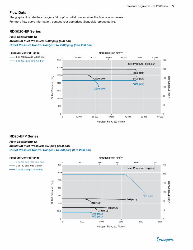
Pressure Regulators—RHPS Series 77 RHPS
REGULATORS
RD(H)20-EF Series
Flow Coefficient: 13Maximum Inlet Pressure: 5800 psig (400 bar)Outlet Pressure Control Range: 0 to 2900 psig (0 to 200 bar)
0
1500
2500
3000
3500
500
1000
2000
0 10 000 30 00020 000 40 000 60 000 50 000
0 10 000 30 00020 000 40 000 60 00050 000
0 15 000 30 000 45 000 60 000 90 00075 000240
40
80
160
200
0
120
200
240
40
160
120
0
80
0
2000
2500
3000
3500
1500
1000
500
0 15 000 30 000 45 000 60 000 90 00075 000
20
24
4.0
16
12
0
8.0
0 15 000 30 000 45 000 60 000 90 00075 000
Nitrogen Flow, std ft3/min
Out
let
Pre
ssur
e, p
sig
Out
let
Pre
ssur
e, b
arO
utle
t P
ress
ure,
psi
g
Out
let
Pre
ssur
e, b
arO
utle
t P
ress
ure,
MP
a
Nitrogen Flow, std ft3/min
Nitrogen Flow, Nm3/h
Nitrogen Flow, Nm3/h
Nitrogen Flow, Nm3/h
5800 (400)
2900 (200)
5800 (400)
5800 (400)2900 (200)
Pressure Control Range
0 to 2537 psig (0 to 175 bar)
0 to 2900 psig (0 to 200 bar)
RDH20-EF Series
USA
EURO
JPN
Flow Coef�cient: 13Maximum Inlet Pressure: RDH20-EF—5800 psig (400 bar)Outlet Pressure Control Range: 0 to 2900 psig (0 to 200 bar)
400 (5800)
200 (2900)
400 (5800)
400 (5800)200 (2900)
40.0
20.0
40.0
40.020.0
Nitrogen Flow, std ft3/min
Out
let
Pre
ssur
e, p
sig
Out
let
Pre
ssur
e, b
ar
Nitrogen Flow, Nm3/h
Inlet Pressure, psig (bar)
Pressure Control Range
0 to 2900 psig (0 to 200 bar)
0 to 2537 psig (0 to 175 bar)
Flow DataThe graphs illustrate the change or “droop” in outlet pressures as the flow rate increases.
For more flow curve information, contact your authorized Swagelok representative.
RD20-EFP Series
Flow Coefficient: 13Maximum Inlet Pressure: 507 psig (35.0 bar)Outlet Pressure Control Range: 0 to 290 psig (0 to 20.0 bar)
0
100
150
200
250
300
350
50.0
0 1000 30002000 4000 5000
0 1000 30002000 4000 5000
0 1500 3000 4500 6000 7500
16.0
20.0
24.0
4.0
12.0
0
8.0
24.0
20.0
4.0
16.0
12.0
0
8.0
0
100
150
250
200
300
350
50.0
0 1500 3000 4500 6000 7500
1500 3000 4500 6000 75000
2.4
2.0
0.8
1.2
1.6
0.4
0
Nitrogen Flow, std ft3/min
Out
let
Pre
ssur
e, p
sig
Out
let
Pre
ssur
e, b
arO
utle
t P
ress
ure,
psi
g
Out
let
Pre
ssur
e, b
arO
utle
t P
ress
ure,
MP
a
Nitrogen Flow, std ft3/min
Nitrogen Flow, Nm3/h
Nitrogen Flow, Nm3/h
Nitrogen Flow, Nm3/h
507(35.0)
35.0 (507)
3.5
218(15.0)
15.0 (218)
1.5
507(35.0)
35.0 (507)
3.5
218(15.0)
15.0 (218)
1.5
507 (35.0)
35.0 (507)
3.5
218 (15.0),507 (35.0)
15.0 (218),35.0 (507)
1.5, 3.5
Pressure Control Range
0 to 43.0 psig (0 to 3.0 bar)
0 to 130 psig (0 to 9.0 bar)
0 to 290 psig (0 to 20.0 bar)
RD20-EFP Series
USA
EURO
JPN
Flow Coef�cient: 13Maximum Inlet Pressure: RD20-EFP—507psig (35.0 bar)Outlet Pressure Control Range: 0 to 290 psig (0 to 20.0 bar)
Nitrogen Flow, std ft3/min
Out
let
Pre
ssur
e, p
sig
Out
let
Pre
ssur
e, b
ar
Nitrogen Flow, Nm3/h
Inlet Pressure, psig (bar)
Pressure Control Range
0 to 290 psig (0 to 20.0 bar)
0 to 130 psig (0 to 9.0 bar)
0 to 43.0 psig (0 to 3.0 bar)

78 Pressure Regulators and FiltersRH
PS
REGU
LATO
RS
Flow DataThe graphs illustrate the change or “droop” in outlet pressures as the flow rate increases.
For more flow curve information, contact your authorized Swagelok representative.
RD25 Series
Flow Coefficient: 21Maximum Inlet Pressure: 1015 psig (70.0 bar)Outlet Pressure Control Range: 0 to 1015 psig (0 to 70.0 bar)
0
300
500
600
700
800
100
200
400
0 3000 90006000 12 000 15 000
0 3000 90006000 12 000 15 000
0 4000 8000 12 000 16 000 20 000
40
50
10
30
0
20
50
10
40
30
0
20
0
400
500
600
700
800
300
200
100
0 4000 8000 12 000 16 000 20 000
4000 8000 12 000 16 000 20 0000
5.0
2.0
3.0
4.0
1.0
0
Nitrogen Flow, std ft3/min
Out
let
Pre
ssur
e, p
sig
Out
let
Pre
ssur
e, b
arO
utle
t P
ress
ure,
psi
g
Out
let
Pre
ssur
e, b
arO
utle
t P
ress
ure,
MP
a
Nitrogen Flow, std ft3/min
Nitrogen Flow, Nm3/h
Nitrogen Flow, Nm3/h
Nitrogen Flow, Nm3/h
580 (40.0)
1015 (70.0)
1015 (70.0)507 (35.0)
40.0 (580)
4.0
70.0 (1015)
7.0
70.0 (1015)
7.0
35.0 (507)
3.5
Pressure Control Range
0 to 290 psig (0 to 20.0 bar)
0 to 1015 psig (0 to 70.0 bar)
RD25 Series
USA
EURO
JPN
Flow Coef�cient: 21Maximum Inlet Pressure: RD25—1015 psig (70.0 bar)Outlet Pressure Control Range: 0 to 1015 psig (0 to 70.0 bar)
Nitrogen Flow, std ft3/min
Out
let
Pre
ssur
e, p
sig
Out
let
Pre
ssur
e, b
ar
Nitrogen Flow, Nm3/h
Inlet Pressure, psig (bar)
Pressure Control Range
0 to 1015 psig (0 to 70.0 bar)
0 to 290 psig (0 to 20.0 bar)
RD25 Series
Flow Coefficient: 21Maximum Inlet Pressure: 507 psig (35.0 bar)Outlet Pressure Control Range: 0 to 130 psig (0 to 9.0 bar)
0
60
100
120
140
20
40
80
0 1500 45003000 6000 7500
0 1500 45003000 6000 7500
0 2000 4000 6000 8000 10 000
7.5
1.5
9.0
3.0
6.0
0
4.5
9.0
1.5
6.0
7.5
4.5
0
3.0
0
60
80
100
120
140
40
20
0 2000 4000 6000 8000 10 000
0.90
0.15
0.60
0.75
0.45
0
0.30
0 2000 4000 6000 8000 10 000
Nitrogen Flow, std ft3/min
Out
let
Pre
ssur
e, p
sig
Out
let
Pre
ssur
e, b
arO
utle
t P
ress
ure,
psi
g
Out
let
Pre
ssur
e, b
arO
utle
t P
ress
ure,
MP
a
Nitrogen Flow, std ft3/min
Nitrogen Flow, Nm3/h
Nitrogen Flow, Nm3/h
Nitrogen Flow, Nm3/h
218 (15.0)
218 (15.0)
507 (35.0)
218 (15.0)
Pressure Control Range
0 to 43.0 psig (0 to 3.0 bar)
0 to 130 psig (0 to 9.0 bar)
RD25 Series
USA
EURO
JPN
Flow Coef�cient: 21Maximum Inlet Pressure: RD25—507 psig (35.0 bar)Outlet Pressure Control Range: 0 to 130 psig (0 to 9.0 bar)
507 (35.0)
507 (35.0)
15.0 (218)
15.0 (218)
35.0 (507)
15.0 (218)35.0 (507)
35.0 (507)
1.5
1.5
3.5
1.53.5
3.5
Nitrogen Flow, std ft3/min
Out
let
Pre
ssur
e, p
sig
Out
let
Pre
ssur
e, b
ar
Nitrogen Flow, Nm3/h
Inlet Pressure, psig (bar)
Pressure Control Range
0 to 130 psig (0 to 9.0 bar)
0 to 43.0 psig (0 to 3.0 bar)

Pressure Regulators—RHPS Series 79 RHPS
REGULATORS
RDH25 Series
Flow Coefficient: 21Maximum Inlet Pressure: 4060 psig (280 bar)Outlet Pressure Control Range: 0 to 362 psig (0 to 25.0 bar)
0
160
240
320
400
80
0 4000 12 0008000 16 000 20 000
0 4000 12 0008000 16 000 20 000
0 6000 12 000 18 000 24 000 30 000
15
20
25
10
0
5.0
25
5.0
20
15
0
10
2.5
0.5
2.0
1.5
0
1.0
0
80
160
240
320
400
0 6000 12 000 18 000 24 000 30 000
6000 12 000 18 000 24 000 30 000
0
0
Nitrogen Flow, std ft3/min
Out
let
Pre
ssur
e, p
sig
Out
let
Pre
ssur
e, b
arO
utle
t P
ress
ure,
psi
g
Out
let
Pre
ssur
e, b
arO
utle
t P
ress
ure,
MP
a
Nitrogen Flow, std ft3/min
Nitrogen Flow, Nm3/h
Nitrogen Flow, Nm3/h
Nitrogen Flow, Nm3/h
2900 (200), 4060 (280)
1015 (70.0)580 (40.0)
580 (40.0), 1015 (70.0), 2900 (200), 4060 (280)
580 (40.0)1015 (70.0), 2900 (200),
4060 (280)
200 (2900), 280 (4060)
70.0 (1015)40.0 (580)
40.0 (580), 70.0 (1015), 200 (2900), 280 (4060)
40.0 (580)70.0 (1015), 200 (2900),
280 (4060)
20.0, 28.0
7.04.0
4.0, 7.0,20.0, 28.0
4.0 7.0, 20.0, 28.0
Pressure Control Range
0 to 145 psig (0 to 10.0 bar)
0 to 362 psig (0 to 25.0 bar)
RDH25 Series
USA
EURO
JPN
Flow Coef�cient: 21Maximum Inlet Pressure: RDH25—4060 psig (280 bar)Outlet Pressure Control Range: 0 to 362 psig (0 to 25.0 bar)
Nitrogen Flow, std ft3/min
Out
let
Pre
ssur
e, p
sig
Out
let
Pre
ssur
e, b
ar
Nitrogen Flow, Nm3/h
Inlet Pressure, psig (bar)
Pressure Control Range
0 to 362 psig (0 to 25.0 bar)
0 to 145 psig (0 to 10.0 bar)
Flow DataThe graphs illustrate the change or “droop” in outlet pressures as the flow rate increases.
For more flow curve information, contact your authorized Swagelok representative.
Nitrogen Flow, std ft3/min
Out
let
Pre
ssur
e, p
sig
Out
let
Pre
ssur
e, b
ar
Nitrogen Flow, Nm3/h
0
1000
1500
2000
3000
3500
500
0 40 00020 00010 000 50 000
0 10 000 30 00020 000 40 000 50 000
0 30 00015 000 45 000 60 000 75 000
160
200
40
120
0
80
240
200
40
160
120
0
80
0
1000
1500
2000
2500
3500
3000
500
0 30 00015 000 45 000 60 000 75 000
15 000 45 00030 000 60 000 75 0000
20
24
16
8.0
12
4.0
0
2500
30 000
240
Nitrogen Flow, std ft3/min
Out
let
Pre
ssur
e, p
sig
Out
let
Pre
ssur
e, b
arO
utle
t P
ress
ure,
psi
g
Out
let
Pre
ssur
e, b
arO
utle
t P
ress
ure,
MP
a
Nitrogen Flow, std ft3/min
Nitrogen Flow, Nm3/h
Nitrogen Flow, Nm3/h
Nitrogen Flow, Nm3/h
2900 (200)
4060 (280)
2900 (200)
2900 (200)
4060 (280)
4060 (280)
4060 (280)
1015 (70.0)
200 (2900)
280 (4060)
200 (2900)
200 (2900)
280 (4060)
280 (4060)
280 (4060)
70.0 (1015)
20.0
28.0
20.0
20.0
28.0
28.0
28.0
7.0
Pressure Control Range
0 to 2537 psig (0 to 175 bar)
0 to 2900 psig (0 to 200 bar)
0 to 1450 psig (0 to 100 bar)
RDH25 Series
USA
EURO
JPN
Flow Coef�cient: 21Maximum Inlet Pressure: RDH25— 4060psig (280 bar)Outlet Pressure Control Range: 0 to 2900 psig (0 to 200 bar)
RDH25 Series
Flow Coefficient: 21Maximum Inlet Pressure: 4060 psig (280 bar)Outlet Pressure Control Range: 0 to 2900 psig (0 to 200 bar)
Inlet Pressure, psig (bar)
Pressure Control Range
0 to 2900 psig (0 to 200 bar)
0 to 2537 psig (0 to 175 bar)
0 to 1450 psig (0 to 100 bar)

80 Pressure Regulators and FiltersRH
PS
REGU
LATO
RS
Flow DataThe graphs illustrate the change or “droop” in outlet pressures as the flow rate increases.
For more flow curve information, contact your authorized Swagelok representative.
RD25-EF Series
Flow Coefficient: 21Maximum Inlet Pressure: 1015 psig (70.0 bar)Outlet Pressure Control Range: 0 to 1015 psig (0 to 70.0 bar)
0
300
200
400
500
700
600
800
100
0 2000 6000 80004000 10 000 12 000
0 2000 60004000 8000 10 000 12 000
0 3000 6000 9000 12 000 15 000 18 000
30
40
50
20
0
10
50
40
30
0
20
10
0
300
400
500
600
700
800
100
200
0 3000 6000 9000 12 000 18 00015 000
5.0
4.0
3.0
0
2.0
1.0
0 3000 6000 9000 12 000 18 00015 000
Nitrogen Flow, std ft3/min
Out
let
Pre
ssur
e, p
sig
Out
let
Pre
ssur
e, b
arO
utle
t P
ress
ure,
psi
g
Out
let
Pre
ssur
e, b
arO
utle
t P
ress
ure,
MP
a
Nitrogen Flow, std ft3/min
Nitrogen Flow, Nm3/h
Nitrogen Flow, Nm3/h
Nitrogen Flow, Nm3/h
507 (35.0) 1015 (70.0)
1015 (70.0)
35.0 (507) 70.0 (1015)
70.0 (1015)
3.5 7.0
7.0
Pressure Control Range
0 to 290 psig (0 to 20.0 bar)
0 to 1015 psig (0 to 70.0 bar)
RD25-EF Series
USA
EURO
JPN
Flow Coef�cient: 21Maximum Inlet Pressure: RD25-EF—1015 psig (70.0 bar)Outlet Pressure Control Range: 0 to 1015 psig (0 to 70.0 bar)
Nitrogen Flow, std ft3/min
Out
let
Pre
ssur
e, p
sig
Out
let
Pre
ssur
e, b
ar
Nitrogen Flow, Nm3/h
Inlet Pressure, psig (bar)
Pressure Control Range
0 to 1015 psig (0 to 70.0 bar)
0 to 290 psig (0 to 20.0 bar)
RD25-EF Series
Flow Coefficient: 21Maximum Inlet Pressure: 507 psig (35.0 bar)Outlet Pressure Control Range: 0 to 130 psig (0 to 9.0 bar)
0
60
40
80
100
120
140
20
0 1000 3000 40002000 5000 6000
0 1000 30002000 4000 5000 6000
0 1500 3000 4500 6000 7500 9000
4.5
6.0
7.5
9.0
3.0
0
1.5
9.0
6.0
7.5
4.5
0
3.0
1.5
0
40
60
80
100
120
140
20
0 1500 3000 4500 6000 90007500
0.90
0.60
0.75
0.45
0
0.30
0.15
0 1500 3000 4500 6000 90007500
Nitrogen Flow, std ft3/min
Out
let
Pre
ssur
e, p
sig
Out
let
Pre
ssur
e, b
arO
utle
t P
ress
ure,
psi
g
Out
let
Pre
ssur
e, b
arO
utle
t P
ress
ure,
MP
a
Nitrogen Flow, std ft3/min
Nitrogen Flow, Nm3/h
Nitrogen Flow, Nm3/h
Nitrogen Flow, Nm3/h
507 (35.0)
218 (15.0)
218 (15.0)
218 (15.0)
507 (35.0)
507 (35.0)
35.0 (507)
15.0 (218)
35.0 (507)
3.5
35.0 (507)
15.0 (218)
1.5
1.5 3.5
15.0 (218)
1.5
3.5
Pressure Control Range
0 to 43.0 psig (0 to 3.0 bar)
0 to 130 psig (0 to 9.0 bar)
RD25-EF Series
USA
EURO
JPN
Flow Coef�cient: 21Maximum Inlet Pressure: RD25-EF—507 psig (35.0 bar)Outlet Pressure Control Range: 0 to 130 psig (0 to 9.0 bar)
Nitrogen Flow, std ft3/min
Out
let
Pre
ssur
e, p
sig
Out
let
Pre
ssur
e, b
ar
Nitrogen Flow, Nm3/h
Inlet Pressure, psig (bar)
Pressure Control Range
0 to 130 psig (0 to 9.0 bar)
0 to 43.0 psig (0 to 3.0 bar)

Pressure Regulators—RHPS Series 81 RHPS
REGULATORS
RDH25-EF Series
Flow Coefficient: 21Maximum Inlet Pressure: 4060 psig (280 bar)Outlet Pressure Control Range: 0 to 362 psig (0 to 25.0 bar)
0
160
240
320
400
80
0 6000 18 00012 000 24 000 30 000
0 6000 18 00012 000 24 000 30 000
0 9000 18 000 27 000 36 000 45 000
15
20
25
10
0
5.0
25
5.0
20
15
0
10
2.5
0.5
2.0
1.5
0
1.0
0
80
160
240
320
400
0 9000 18 000 27 000 36 000 45 000
9000 18 000 27 000 36 000 45 000
0
0
Nitrogen Flow, std ft3/min
Out
let
Pre
ssur
e, p
sig
Out
let
Pre
ssur
e, b
arO
utle
t P
ress
ure,
psi
g
Out
let
Pre
ssur
e, b
arO
utle
t P
ress
ure,
MP
a
Nitrogen Flow, std ft3/min
Nitrogen Flow, Nm3/h
Nitrogen Flow, Nm3/h
Nitrogen Flow, Nm3/h
2900 (200), 4060 (280)1015 (70.0)580 (40.0)
580 (40.0)
2900 (200), 4060 (280)
200 (2900), 280 (4060)70.0 (1015)40.0 (580)
40.0 (580), 70.0 (1015), 200 (2900), 280 (4060)
40.0 (580)
200 (2900), 280 (4060)
20.0, 28.0
7.04.0
4.0, 7.0,20.0, 28.0
4.0 20.0, 28.0
Pressure Control Range
0 to 145 psig (0 to 10.0 bar)
0 to 362 psig (0 to 25.0 bar)
RDH25-EF Series
USA
EURO
JPN
Flow Coef�cient: 21Maximum Inlet Pressure: RDH25-EF—4060 psig (280 bar)Outlet Pressure Control Range: 0 to 362 psig (0 to 25.0 bar)
580 (40.0), 1015 (70.0), 2900 (200), 4060 (280)
1015 (70.0)
70.0 (1015)
7.0
Nitrogen Flow, std ft3/min
Out
let
Pre
ssur
e, p
sig
Out
let
Pre
ssur
e, b
ar
Nitrogen Flow, Nm3/h
Inlet Pressure, psig (bar)
Pressure Control Range
0 to 362 psig (0 to 25.0 bar)
0 to 145 psig (0 to 10.0 bar)
Flow DataThe graphs illustrate the change or “droop” in outlet pressures as the flow rate increases.
For more flow curve information, contact your authorized Swagelok representative.
Nitrogen Flow, std ft3/min
Out
let
Pre
ssur
e, p
sig
Out
let
Pre
ssur
e, b
ar
Nitrogen Flow, Nm3/h
0
1000
1500
2000
3000
3500
500
0 40 00020 00010 000 50 000
0 10 000 30 00020 000 40 000 50 000
0 30 00015 000 45 000 60 000 75 000
160
200
40
120
0
80
240
200
40
160
120
0
80
0
1000
1500
2000
2500
3500
3000
500
0 30 00015 000 45 000 60 000 75 000
15 000 45 00030 000 60 000 75 0000
20
24
16
8.0
12
4.0
0
2500
30 000
240
Nitrogen Flow, std ft3/min
Out
let
Pre
ssur
e, p
sig
Out
let
Pre
ssur
e, b
arO
utle
t P
ress
ure,
psi
g
Out
let
Pre
ssur
e, b
arO
utle
t P
ress
ure,
MP
a
Nitrogen Flow, std ft3/min
Nitrogen Flow, Nm3/h
Nitrogen Flow, Nm3/h
Nitrogen Flow, Nm3/h
2900 (200)
4060 (280)
2900 (200)
2900 (200)
4060 (280)
4060 (280)
4060 (280)
1015 (70.0)
200 (2900)
280 (4060)
200 (2900)
200 (2900)
280 (4060)
280 (4060)
280 (4060)
70.0 (1015)
20.0
28.0
20.0
20.0
28.0
28.0
28.0
7.0
Pressure Control Range
0 to 2537 psig (0 to 175 bar)
0 to 2900 psig (0 to 200 bar)
0 to 1450 psig (0 to 100 bar)
RDH25-EF Series
USA
EURO
JPN
Flow Coef�cient: 21Maximum Inlet Pressure: RDH25-EF— 4060psig (280 bar)Outlet Pressure Control Range: 0 to 2900 psig (0 to 200 bar)
RDH25-EF Series
Flow Coefficient: 21Maximum Inlet Pressure: 4060 psig (280 bar)Outlet Pressure Control Range: 0 to 2900 psig (0 to 200 bar)
Inlet Pressure, psig (bar)
Pressure Control Range
0 to 2900 psig (0 to 200 bar)
0 to 2537 psig (0 to 175 bar)
0 to 1450 psig (0 to 100 bar)

82 Pressure Regulators and FiltersRH
PS
REGU
LATO
RS
RD25-EFP Series
Flow Coefficient: 21Maximum Inlet Pressure: 507 psig (35.0 bar)Outlet Pressure Control Range: 0 to 290 psig (0 to 20.0 bar)
0
100
150
200
300
350
50.0
0 400020001000 5000 6000
0 1000 30002000 4000 5000 6000
0 30001500 4500 6000 7500 9000
16.0
20.0
4.0
12.0
0
8.0
24.0
20.0
4.0
16.0
12.0
0
8.0
0
100
150
200
250
350
300
50.0
0 30001500 4500 6000 7500 9000
1500 45003000 6000 7500 90000
2.0
2.4
1.6
0.8
1.2
0.4
0
250
3000
24.0
Nitrogen Flow, std ft3/min
Out
let
Pre
ssur
e, p
sig
Out
let
Pre
ssur
e, b
arO
utle
t P
ress
ure,
psi
g
Out
let
Pre
ssur
e, b
arO
utle
t P
ress
ure,
MP
a
Nitrogen Flow, std ft3/min
Nitrogen Flow, Nm3/h
Nitrogen Flow, Nm3/h
Nitrogen Flow, Nm3/h
507 (35.0)
507 (35.0)
218 (15.0)
15.0 (218)
15.0 (218)
218 (15.0)
507 (35.0)
35.0 (507)
35.0 (507)
35.0 (507)
3.5
3.51.5
1.5
3.5
218 (15.0)
507 (35.0)
15.0 (218)
35.0 (507)
3.5
1.5
Pressure Control Range
0 to 43.0 psig (0 to 3.0 bar)
0 to 130 psig (0 to 9.0 bar)
0 to 290 psig (0 to 20.0 bar)
RD25-EFP Series
USA
EURO
JPN
Flow Coef�cient: 21Maximum Inlet Pressure: RD25-EFP— 507psig (35.0 bar)Outlet Pressure Control Range: 0 to 290 psig (0 to 20.0 bar)
Nitrogen Flow, std ft3/min
Out
let
Pre
ssur
e, p
sig
Out
let
Pre
ssur
e, b
ar
Nitrogen Flow, Nm3/h
Inlet Pressure, psig (bar)
Pressure Control Range
0 to 290 psig (0 to 20.0 bar)
0 to 130 psig (0 to 9.0 bar)
0 to 43.0 psig (0 to 3.0 bar)
Flow DataThe graphs illustrate the change or “droop” in outlet pressures as the flow rate increases.
For more flow curve information, contact your authorized Swagelok representative.

Pressure Regulators—RHPS Series 83 RHPS
REGULATORS
DimensionsDimensions, in inches (millimeters), are for reference only and are subject to change.
Ordering InformationBuild an RD(H)20 and RD(H)25 series regulator ordering number by combining the designators in the sequence shown below.
Series
End Connection
Size
Dimensions, in. (mm)
A B C D E
RD(H)20 2 in. 9.33 (237) 7.28 (185) 2.44 (62.0) 4.33 (110) 5.51 (140)
RD(H)25 2 1/2 in. 11.8 (300) 9.25 (235) 3.42 (87.0) 4.92 (125) 6.69 (170)
B
A
D
Shown with RS2 series pilot regulator.
E
C
Top Side
11 Options EF = External feedback to main
regulator EFP = External feedback to pilot
regulator, limited to 290 psig (20.0 bar)
N = NACE MR0175/ISO 15156 G93 = ASTM G93 Level C-cleaned
6 Body Material 02 = 316L SS
7 Pilot Regulator OptionsPressure Control Range X = No pilot regulator, optionalRD series with LRS4 series pilot regulator 0 = 0 to 43 psig (0 to 3.0 bar) 1 = 0 to 130 psig (0 to 9.0 bar) 2 = 0 to 290 psig (0 to 20.0 bar)RD series with RS2 series pilot regulator 3 = 0 to 1015 psig (0 to 70.0 bar)RDH series with RS2 series pilot regulator 4 = 0 to 145 psig (0 to 10.0 bar) 5 = 0 to 362 psig (0 to 25.0 bar) 6 = 0 to 1450 psig (0 to 100 bar) 7 = 0 to 2537 psig (0 to 175 bar) 8 = 0 to 2900 psig (0 to 200 bar)
10 Seat Seal MaterialRD series V = Fluorocarbon FKM N = Nitrile E = EPDM L = Low temperature NitrileRDH series K = PCTFE P = PEEK
1 Series RD = 1015 psig (70.0 bar) maximum
inlet pressure (507 psig [35.0 bar] with pilot regulator, options 0, 1, or 2)
RDH = 5800 psig (400 bar) maximum inlet pressure (RDH20); 4060 psig (280 bar) maximum inlet pressure (RDH25)
8 Seal Material V = Fluorocarbon FKM N = Nitrile E = EPDM L = Low temperature Nitrile
9 Diaphragm Material V = Fluorocarbon FKM N = Nitrile E = EPDM L = Low temperature Nitrile
5 Flange Facing Omit designator if flanges are not ordered.
1 = Raised face smooth 3 = RTJ
RD FA 20 A 1 - 02 - 0 - V V V - EF2 41 3 5 6 7 8 9 10 11
2 Inlet / Outlet B = Female ISO/BSP parallel thread➀ N = Female NPT➀ FA = ASME B16.5 flange FD = EN 1092 (DIN) flange➀ RD(H)20 only.
4 Pressure Class Omit designator if flanges are not ordered.
A = ASME class 150 B = ASME class 300 C = ASME class 600 E = ASME class 1500 F = ASME class 2500 M = EN class PN16 N = EN class PN40
3 Size 20 = 2 in. / DN50 25 = 2 1/2 in. / DN65

84 Pressure Regulators and FiltersRH
PS
REGU
LATO
RS
Features■Balanced poppet design
■Diaphragm sensing
■Integral pilot regulator with dynamic regulation
■Dome-to-outlet pressure ratio approximately 1:1
■Large dome for stability
■Floating seat for improved sealing reliability (patent pending)
Options■External feedback (EF) for improved
performance
■EF to main regulator limited by standard outlet pressure range
■EF to pilot regulator limited to 290 psig (20.0 bar)
■NACE MR0175/ISO 15156-compliant models
■Special cleaning to ASTM G93 Level C
Integral Pilot-Operated, Dome-Loaded Pressure-Reducing Regulators— RD(H)30 and RD(H)40 Series
Technical Data
Series
Maximum Inlet
Pressurepsig (bar)
Maximum Outlet Control
Pressurepsig (bar)
Sensing Type
Temperature Range °F (C°)
Flow Coefficient
(Cv)
Seat Diameterin. (mm)
Inlet and Outlet
ConnectionsGauge / Dome
Connection
Weight(With Class
150 Flanges)lb (kg)
RD
1015 (70.0) (507 [35.0]
with LRS4 pilot regulator)
1015 (70.0)Diaphragm
–49 to 176 (–45 to 80)
See Pressure-Temperature
Ratings, page 921.
RD(H)30: 36
RD(H)40: 73
RD(H)30: 1.65 (42.0)
RD(H)40: 2.36 (60.0)
EN or ASME flanges—
RD(H)30: 3 in.
RD(H)40: 4 in.
Use P1 gauge connection of pilot regulator.
Dome: 1/4 in. ISO/BSP
parallel thread
RD(H)30: 136 (62)
RD(H)40: 183 (83)
RDH 4060 (280) 2900 (200)
Component Material / Specification
1 Cap screw A4-80
2 Washer A4
3 Dome 316L SS / A479
4 Dome plate 316L SS / A479
5 Diaphragm EPDM, FKM, or nitrile
6 Conical spring (RD[H]30 only) 302 SS / A313
7 Diaphragm plate 316L SS / A479
8 Retaining ring Commercial stainless steel
9 Body assembly (body, reducers, flanges) 316L SS / A479
10 Body plate
11 Poppet 316L SS / A479
12 O-ring EPDM, FKM, or nitrile
13 Seat 316L SS / A479
14 Seat sealRD EPDM, FKM, or nitrile
RDH PEEK
15 Poppet housing 316L SS / A479
16 O-ringEPDM, FKM, or nitrile
17 Plug O-ring
18 Guide ring PTFE
19 Poppet spring 302 SS / A313
20 Body plug 316L SS / A479
21 Washer A4
22 Cap Screw A4-80
Wetted lubricants: Silicone-based and synthetic hydrocarbon-based
Wetted components listed in italics. Gauge plugs (not shown): 431 SS / A276.
Materials of Construction
RD30 Series Regulator
12345
7
12
1098
13
11
15
17
14 1920
18
6
16 21 22
RD Poppet and Seat
RDH Poppet and Seat
See pages 85 to 97 for flow data.
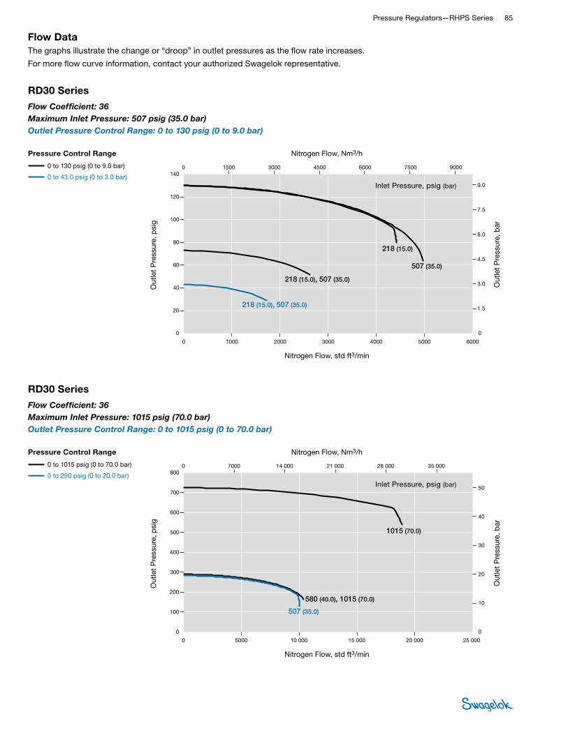
Pressure Regulators—RHPS Series 85 RHPS
REGULATORS
Flow DataThe graphs illustrate the change or “droop” in outlet pressures as the flow rate increases.
For more flow curve information, contact your authorized Swagelok representative.
RD30 Series
Flow Coefficient: 36Maximum Inlet Pressure: 1015 psig (70.0 bar)Outlet Pressure Control Range: 0 to 1015 psig (0 to 70.0 bar)
0
300
500
600
700
800
100
200
400
0 5000 15 00010 000 20 000 25 000
0 5000 15 00010 000 20 000 25 000
0 7000 14 000 21 000 28 000 35 000
40
50
10
30
0
20
50
10
40
30
0
20
0
400
500
600
700
800
300
200
100
0 7000 14 000 21 000 28 000 35 000
7000 14 000 21 000 28 000 35 0000
5.0
2.0
3.0
4.0
1.0
0
Nitrogen Flow, std ft3/min
Out
let
Pre
ssur
e, p
sig
Out
let
Pre
ssur
e, b
arO
utle
t P
ress
ure,
psi
g
Out
let
Pre
ssur
e, b
arO
utle
t P
ress
ure,
MP
a
Nitrogen Flow, std ft3/min
Nitrogen Flow, Nm3/h
Nitrogen Flow, Nm3/h
Nitrogen Flow, Nm3/h
1015 (70.0)
580 (40.0), 1015 (70.0)
507 (35.0)
70.0 (1015)
4.0, 7.0
40.0 (580), 70.0 (1015)
7.0
35.0 (507)
3.5
Pressure Control Range
0 to 290 psig (0 to 20.0 bar)
0 to 1015 psig (0 to 70.0 bar)
RD30 Series
USA
EURO
JPN
Flow Coef�cient: 36Maximum Inlet Pressure: RD30—1015 psig (70.0 bar)Outlet Pressure Control Range: 0 to 1015 psig (0 to 70.0 bar)
Nitrogen Flow, std ft3/min
Out
let
Pre
ssur
e, p
sig
Out
let
Pre
ssur
e, b
ar
Nitrogen Flow, Nm3/h
Inlet Pressure, psig (bar)
Pressure Control Range
0 to 1015 psig (0 to 70.0 bar)
0 to 290 psig (0 to 20.0 bar)
RD30 Series
Flow Coefficient: 36Maximum Inlet Pressure: 507 psig (35.0 bar)Outlet Pressure Control Range: 0 to 130 psig (0 to 9.0 bar)
0
60
40
80
100
120
140
20
0 1000 3000 40002000 5000 6000
0 1000 30002000 4000 5000 6000
0 1500 3000 4500 6000 7500 9000
4.5
6.0
7.5
9.0
3.0
0
1.5
9.0
6.0
7.5
4.5
0
3.0
1.5
0
40
60
80
100
120
140
20
0 1500 3000 4500 6000 90007500
0.90
0.60
0.75
0.45
0
0.30
0.15
0 1500 3000 4500 6000 90007500
Nitrogen Flow, std ft3/min
Out
let
Pre
ssur
e, p
sig
Out
let
Pre
ssur
e, b
arO
utle
t P
ress
ure,
psi
g
Out
let
Pre
ssur
e, b
arO
utle
t P
ress
ure,
MP
a
Nitrogen Flow, std ft3/min
Nitrogen Flow, Nm3/h
Nitrogen Flow, Nm3/h
Nitrogen Flow, Nm3/h
218 (15.0), 507 (35.0)
218 (15.0)
218 (15.0), 507 (35.0)
507 (35.0)
15.0 (218), 35.0 (507)
35.0 (507)
15.0 (218)
1.5
1.5, 3.5
3.5
15.0 (218), 35.0 (507)
1.5, 3.5
Pressure Control Range
0 to 43.0 psig (0 to 3.0 bar)
0 to 130 psig (0 to 9.0 bar)
RD30 Series
USA
EURO
JPN
Flow Coef�cient: 36Maximum Inlet Pressure: RD30—507 psig (35.0 bar)Outlet Pressure Control Range: 0 to 130 psig (0 to 9.0 bar)
Nitrogen Flow, std ft3/min
Out
let
Pre
ssur
e, p
sig
Out
let
Pre
ssur
e, b
ar
Nitrogen Flow, Nm3/h
Inlet Pressure, psig (bar)
Pressure Control Range
0 to 130 psig (0 to 9.0 bar)
0 to 43.0 psig (0 to 3.0 bar)

86 Pressure Regulators and FiltersRH
PS
REGU
LATO
RS
Flow DataThe graphs illustrate the change or “droop” in outlet pressures as the flow rate increases.
For more flow curve information, contact your authorized Swagelok representative.
RDH30 Series
Flow Coefficient: 36Maximum Inlet Pressure: 4060 psig (280 bar)Outlet Pressure Control Range: 0 to 362 psig (0 to 25.0 bar)
0
150
250
300
350
400
50
100
200
0 4000 60002000 10 0008000 12 000 14 000
0 40002000 6000 10 0008000 12 000 14 000
0 4000 8000 12 000 16 000 20 000
20
25
5.0
15
0
10
25
5.0
20
15
0
10
0
200
250
300
350
400
150
100
50
0 4000 8000 12 000 16 000 20 000
4000 8000 12 000 16 000 20 0000
2.5
1.0
1.5
2.0
0.5
0
Nitrogen Flow, std ft3/min
Out
let
Pre
ssur
e, p
sig
Out
let
Pre
ssur
e, b
arO
utle
t P
ress
ure,
psi
g
Out
let
Pre
ssur
e, b
arO
utle
t P
ress
ure,
MP
a
Nitrogen Flow, std ft3/min
Nitrogen Flow, Nm3/h
Nitrogen Flow, Nm3/h
Nitrogen Flow, Nm3/h
580 (40.0)
70.0 (1015), 200 (2900), 280 (4060)
7.0, 20.0, 28.0
40.0 (580)
4.0
Pressure Control Range
0 to 145 psig (0 to 10.0 bar)
0 to 362 psig (0 to 25.0 bar)
RDH30 Series
USA
EURO
JPN
Flow Coef�cient: 36Maximum Inlet Pressure: RDH30—4060 psig (280 bar)Outlet Pressure Control Range: 0 to 362 psig (0 to 25.0 bar)
580 (40.0), 1015 (70.0), 2900 (200), 4060 (280)
580 (40.0), 1015 (70.0), 2900 (200), 4060 (280)
1015 (70.0), 2900 (200), 4060 (280)
40.0 (580), 70.0 (1015), 200 (2900), 280 (4060)
40.0 (580), 70.0 (1015), 200 (2900), 280 (4060)
4.0, 7.0, 20.0, 28.0
4.0, 7.0, 20.0, 28.0
Nitrogen Flow, std ft3/min
Out
let
Pre
ssur
e, p
sig
Out
let
Pre
ssur
e, b
ar
Nitrogen Flow, Nm3/h
Inlet Pressure, psig (bar)
Pressure Control Range
0 to 362 psig (0 to 25.0 bar)
0 to 145 psig (0 to 10.0 bar)
RDH30 Series
Flow Coefficient: 36Maximum Inlet Pressure: 4060 psig (280 bar)Outlet Pressure Control Range: 0 to 1450 psig (0 to 100 bar)
0
600
400
800
1000
1400
1200
1600
200
0 10 000 30 000 40 00020 000 50 000 60 000
0 10 000 30 00020 000 40 000 50 000 60 000
0 15 000 30 000 45 000 60 000 75 000 90 000
60
80
100
40
0
20
100
80
60
0
40
20
0
600
800
1000
1200
1400
1600
200
400
0 15 000 30 000 45 000 60 000 90 00075 000
10
8.0
6.0
0
4.0
2.0
0 15 000 30 000 45 000 60 000 90 00075 000
Nitrogen Flow, std ft3/min
Out
let
Pre
ssur
e, p
sig
Out
let
Pre
ssur
e, b
arO
utle
t P
ress
ure,
psi
g
Out
let
Pre
ssur
e, b
arO
utle
t P
ress
ure,
MP
a
Nitrogen Flow, std ft3/min
Nitrogen Flow, Nm3/h
Nitrogen Flow, Nm3/h
Nitrogen Flow, Nm3/h
2900 (200), 4060 (280)
2900 (200), 4060 (280)
200 (2900), 280 (4060)
20.0, 28.0
7.0
20.0, 28.0
200 (2900), 280 (4060)
Pressure Control Range
0 to 1450 psig (0 to 100 bar)
RDH30 Series
USA
EURO
JPN
Flow Coef�cient: 36Maximum Inlet Pressure: RDH30—4060 psig (280 bar)Outlet Pressure Control Range: 0 to 1450 psig (0 to 100 bar)
1015 (70.0)
70.0 (1015)
Nitrogen Flow, std ft3/min
Out
let
Pre
ssur
e, p
sig
Out
let
Pre
ssur
e, b
ar
Nitrogen Flow, Nm3/h
Inlet Pressure, psig (bar)
Pressure Control Range
0 to 1450 psig (0 to 100 bar)

Pressure Regulators—RHPS Series 87 RHPS
REGULATORS
Flow DataThe graphs illustrate the change or “droop” in outlet pressures as the flow rate increases.
For more flow curve information, contact your authorized Swagelok representative.
RDH30 Series
Flow Coefficient: 36Maximum Inlet Pressure: 4060 psig (280 bar)Outlet Pressure Control Range: 0 to 2900 psig (0 to 200 bar)
0
1000
1500
2000
3000
3500
500
0 80 00040 00020 000 100 000
0 20 000 60 00040 000 80 000 100 000
0 60 00030 000 90 000 120 000 150 000
160
200
40
120
0
80
240
200
40
160
120
0
80
0
1000
1500
2000
2500
3500
3000
500
0 60 00030 000 90 000 120 000 150 000
30 000 90 00060 000 120 000 150 0000
20
24
16
8.0
12
4.0
0
2500
60 000
240
Nitrogen Flow, std ft3/min
Out
let
Pre
ssur
e, p
sig
Out
let
Pre
ssur
e, b
arO
utle
t P
ress
ure,
psi
g
Out
let
Pre
ssur
e, b
arO
utle
t P
ress
ure,
MP
a
Nitrogen Flow, std ft3/min
Nitrogen Flow, Nm3/h
Nitrogen Flow, Nm3/h
Nitrogen Flow, Nm3/h
4060 (280)
2900 (200)
4060 (280)
280 (4060)
200 (2900)
280 (4060)
28.0
20.0
28.0
Pressure Control Range
0 to 2537 psig (0 to 175 bar)
0 to 2900 psig (0 to 200 bar)
RDH30 Series
USA
EURO
JPN
Flow Coef�cient: 36Maximum Inlet Pressure: RDH30—4060 psig (280 bar)Outlet Pressure Control Range: 0 to 2900 psig (0 to 200 bar)
Nitrogen Flow, std ft3/min
Out
let
Pre
ssur
e, p
sig
Out
let
Pre
ssur
e, b
ar
Nitrogen Flow, Nm3/h
Inlet Pressure, psig (bar)
Pressure Control Range
0 to 2900 psig (0 to 200 bar)
0 to 2537 psig (0 to 175 bar)

88 Pressure Regulators and FiltersRH
PS
REGU
LATO
RS
Flow DataThe graphs illustrate the change or “droop” in outlet pressures as the flow rate increases.
For more flow curve information, contact your authorized Swagelok representative.
RD30-EF Series
Flow Coefficient: 36Maximum Inlet Pressure: 1015 psig (70.0 bar)Outlet Pressure Control Range: 0 to 1015 psig (0 to 70.0 bar)
0
300
500
600
700
800
100
200
400
0 5000 15 00010 000 20 000 25 000
0 5000 15 00010 000 20 000 25 000
0 7000 14 000 21 000 28 000 35 000
40
50
10
30
0
20
50
10
40
30
0
20
0
400
500
600
700
800
300
200
100
0 7000 14 000 21 000 28 000 35 000
7000 14 000 21 000 28 000 35 0000
5.0
2.0
3.0
4.0
1.0
0
Nitrogen Flow, std ft3/min
Out
let
Pre
ssur
e, p
sig
Out
let
Pre
ssur
e, b
arO
utle
t P
ress
ure,
psi
g
Out
let
Pre
ssur
e, b
arO
utle
t P
ress
ure,
MP
a
Nitrogen Flow, std ft3/min
Nitrogen Flow, Nm3/h
Nitrogen Flow, Nm3/h
Nitrogen Flow, Nm3/h
1015 (70.0)
1015 (70.0)580 (40.0)
507 (35.0)
70.0 (1015)
70.0 (1015)
4.0
40.0 (580)
7.0
7.0
35.0 (507)
3.5
Pressure Control Range
0 to 290 psig (0 to 20.0 bar)
0 to 1015 psig (0 to 70.0 bar)
RD30-EF Series
USA
EURO
JPN
Flow Coef�cient: 36Maximum Inlet Pressure: RD30-EF—1015 psig (70.0 bar)Outlet Pressure Control Range: 0 to 1015 psig (0 to 70.0 bar)
Nitrogen Flow, std ft3/min
Out
let
Pre
ssur
e, p
sig
Out
let
Pre
ssur
e, b
ar
Nitrogen Flow, Nm3/h
Inlet Pressure, psig (bar)
Pressure Control Range
0 to 1015 psig (0 to 70.0 bar)
0 to 290 psig (0 to 20.0 bar)
RD30-EF Series
Flow Coefficient: 36Maximum Inlet Pressure: 507 psig (35.0 bar)Outlet Pressure Control Range: 0 to 130 psig (0 to 9.0 bar)
0
60
40
80
100
120
140
20
0 2000 6000 80004000 10 000 12 000
0 2000 60004000 8000 10 000 12 000
0 3000 6000 9000 12 000 15 000 18 000
4.5
6.0
7.5
9.0
3.0
0
1.5
9.0
6.0
7.5
4.5
0
3.0
1.5
0
40
60
80
100
120
140
20
0 3000 6000 9000 12 000 18 00015 000
0.90
0.60
0.75
0.45
0
0.30
0.15
0 3000 6000 9000 12 000 18 00015 000
Nitrogen Flow, std ft3/min
Out
let
Pre
ssur
e, p
sig
Out
let
Pre
ssur
e, b
arO
utle
t P
ress
ure,
psi
g
Out
let
Pre
ssur
e, b
arO
utle
t P
ress
ure,
MP
a
Nitrogen Flow, std ft3/min
Nitrogen Flow, Nm3/h
Nitrogen Flow, Nm3/h
Nitrogen Flow, Nm3/h
218 (15.0)
218 (15.0)
218 (15.0)
507 (35.0)
507 (35.0)
15.0 (218)
35.0 (507)
35.0 (507)
15.0 (218)
15.0 (218)
1.5
1.5
1.5
3.5
3.5
3.5
Pressure Control Range
0 to 43.0 psig (0 to 3.0 bar)
0 to 130 psig (0 to 9.0 bar)
RD30-EF Series
USA
EURO
JPN
Flow Coef�cient: 36Maximum Inlet Pressure: RD30-EF—507 psig (35.0 bar)Outlet Pressure Control Range: 0 to 130 psig (0 to 9.0 bar)
507 (35.0)
35.0 (507)
Nitrogen Flow, std ft3/min
Out
let
Pre
ssur
e, p
sig
Out
let
Pre
ssur
e, b
ar
Nitrogen Flow, Nm3/h
Inlet Pressure, psig (bar)
Pressure Control Range
0 to 130 psig (0 to 9.0 bar)
0 to 43.0 psig (0 to 3.0 bar)

Pressure Regulators—RHPS Series 89 RHPS
REGULATORS
Flow DataThe graphs illustrate the change or “droop” in outlet pressures as the flow rate increases.
For more flow curve information, contact your authorized Swagelok representative.
RDH30-EF Series
Flow Coefficient: 36Maximum Inlet Pressure: 4060 psig (280 bar)Outlet Pressure Control Range: 0 to 1450 psig (0 to 100 bar)
0
600
400
800
1000
1400
1200
1600
200
0 15 000 45 000 60 00030 000 75 000 90 000
0 15 000 45 00030 000 60 000 75 000 90 000
0 20 000 40 000 60 000 80 000 100 000 140 000120 000
60
80
100
40
0
20
100
80
60
0
40
20
0
600
800
1000
1200
1400
1600
200
400
0 20 000 40 000 60 000 80 000 120 000 140 000100 000
10
8.0
6.0
0
4.0
2.0
0 20 000 40 000 60 000 80 000 120 000 140 000100 000
Nitrogen Flow, std ft3/min
Out
let
Pre
ssur
e, p
sig
Out
let
Pre
ssur
e, b
arO
utle
t P
ress
ure,
psi
g
Out
let
Pre
ssur
e, b
arO
utle
t P
ress
ure,
MP
a
Nitrogen Flow, std ft3/min
Nitrogen Flow, Nm3/h
Nitrogen Flow, Nm3/h
Nitrogen Flow, Nm3/h
4060 (280) 2900 (200)
4060 (280)
2900 (200)
200 (2900)
200 (2900)
7.0
28.0
28.0
20.0
20.0
280 (4060)
280 (4060)
Pressure Control Range
0 to 1450 psig (0 to 100 bar)
RDH30-EF Series
USA
EURO
JPN
Flow Coef�cient: 36Maximum Inlet Pressure: RDH30-EF—4060 psig (280 bar)Outlet Pressure Control Range: 0 to 1450 psig (0 to 100 bar)
1015 (70.0)
70.0 (1015)
Nitrogen Flow, std ft3/min
Out
let
Pre
ssur
e, p
sig
Out
let
Pre
ssur
e, b
ar
Nitrogen Flow, Nm3/h
Inlet Pressure, psig (bar)
Pressure Control Range
0 to 1450 psig (0 to 100 bar)
RDH30-EF Series
Flow Coefficient: 36Maximum Inlet Pressure: 4060 psig (280 bar)Outlet Pressure Control Range: 0 to 362 psig (0 to 25.0 bar)
0
150
250
300
350
400
50
100
200
0 10 000 15 0005000 25 00020 000 30 000 35 000
0 10 0005000 15 000 25 00020 000 30 000 35 000
0 10 000 20 000 30 000 40 000 50 000
20
25
5.0
15
0
10
25
5.0
20
15
0
10
0
200
250
300
350
400
150
100
50
0 10 000 20 000 30 000 40 000 50 000
10 000 20 000 30 000 40 000 50 0000
2.5
1.0
1.5
2.0
0.5
0
Nitrogen Flow, std ft3/min
Out
let
Pre
ssur
e, p
sig
Out
let
Pre
ssur
e, b
arO
utle
t P
ress
ure,
psi
g
Out
let
Pre
ssur
e, b
arO
utle
t P
ress
ure,
MP
a
Nitrogen Flow, std ft3/min
Nitrogen Flow, Nm3/h
Nitrogen Flow, Nm3/h
Nitrogen Flow, Nm3/h
580 (40.0)
200 (2900), 280 (4060)
20.0, 28.0
40.0 (580)
4.0
Pressure Control Range
0 to 145 psig (0 to 10.0 bar)
0 to 362 psig (0 to 25.0 bar)
RDH30-EF Series
USA
EURO
JPN
Flow Coef�cient: 36Maximum Inlet Pressure: RDH30-EF—4060 psig (280 bar)Outlet Pressure Control Range: 0 to 362 psig (0 to 25.0 bar)
580 (40.0), 1015 (70.0), 2900 (200), 4060 (280)
1015 (70.0), 2900 (200), 4060 (280)
2900 (200), 4060 (280)
70.0 (1015), 200 (2900), 280 (4060)
40.0 (580), 70.0 (1015), 200 (2900), 280 (4060)
7.0, 20.0, 28.0
4.0, 7.0, 20.0, 28.0
1015 (70.0)
580 (40.0)
70.0 (1015)
40.0 (580)
7.0
4.0
Nitrogen Flow, std ft3/min
Out
let
Pre
ssur
e, p
sig
Out
let
Pre
ssur
e, b
ar
Nitrogen Flow, Nm3/h
Inlet Pressure, psig (bar)
Pressure Control Range
0 to 362 psig (0 to 25.0 bar)
0 to 145 psig (0 to 10.0 bar)

90 Pressure Regulators and FiltersRH
PS
REGU
LATO
RS
RDH30-EF Series
Flow Coefficient: 36Maximum Inlet Pressure: 4060 psig (280 bar)Outlet Pressure Control Range: 0 to 2900 psig (0 to 200 bar)
0
1500
2500
3000
3500
500
1000
2000
0 15 000 45 00030 000 60 000 90 000 75 000
0 15 000 45 00030 000 60 000 90 00075 000
0 40 00020 000 60 000 80 000 100 000 140 000120 000240
40
80
160
200
0
120
200
240
40
160
120
0
80
0
2000
2500
3000
3500
1500
1000
500
0 20 000 40 000 60 000 80 000 140 000120 000100 000
20 000 40 000 60 000 80 000 140 000120 000100 000
20
24
4.0
16
12
0
8.0
0
4060 (280)4060 (280)
4060 (280)
2900 (200)
Nitrogen Flow, std ft3/min
Out
let
Pre
ssur
e, p
sig
Out
let
Pre
ssur
e, b
arO
utle
t P
ress
ure,
psi
g
Out
let
Pre
ssur
e, b
arO
utle
t P
ress
ure,
MP
a
Nitrogen Flow, std ft3/min
Nitrogen Flow, Nm3/h
Nitrogen Flow, Nm3/h
Nitrogen Flow, Nm3/h
Pressure Control Range
0 to 2900 psig (0 to 200 bar)
0 to 2537 psig (0 to 175 bar)
RDH30-EF Series
USA
EURO
JPN
Flow Coef�cient: 36Maximum Inlet Pressure: RDH30-EF—4060 psig (280 bar)Outlet Pressure Control Range: 0 to 2900 psig (0 to 200 bar)
280 (4060)
280 (4060)
280 (4060)
200 (2900)
28.028.0
28.0
20.0
Nitrogen Flow, std ft3/min
Out
let
Pre
ssur
e, p
sig
Out
let
Pre
ssur
e, b
ar
Nitrogen Flow, Nm3/h
Inlet Pressure, psig (bar)
Pressure Control Range
0 to 2900 psig (0 to 200 bar)
0 to 2537 psig (0 to 175 bar)
Flow DataThe graphs illustrate the change or “droop” in outlet pressures as the flow rate increases.
For more flow curve information, contact your authorized Swagelok representative.

Pressure Regulators—RHPS Series 91 RHPS
REGULATORS
Flow DataThe graphs illustrate the change or “droop” in outlet pressures as the flow rate increases.
For more flow curve information, contact your authorized Swagelok representative.
RD30-EFP Series
Flow Coefficient: 36Maximum Inlet Pressure: 507 psig (35.0 bar)Outlet Pressure Control Range: 0 to 290 psig (0 to 20.0 bar)
0
150
250
300
350
50
100
200
0 2000 60004000 8000 12 000 10 000
0 2000 60004000 8000 12 00010 000
0 3000 6000 9000 12 000 18 00015 00024
4.0
8.0
16
20
0
12
20
24
4.0
16
12
0
8.0
0
200
250
300
350
150
100
50
0 3000 6000 9000 12 000 18 00015 000
2.0
2.4
0.4
1.6
1.2
0
0.8
0 3000 6000 9000 12 000 18 00015 000
Nitrogen Flow, std ft3/min
Out
let
Pre
ssur
e, p
sig
Out
let
Pre
ssur
e, b
arO
utle
t P
ress
ure,
psi
g
Out
let
Pre
ssur
e, b
arO
utle
t P
ress
ure,
MP
a
Nitrogen Flow, std ft3/min
Nitrogen Flow, Nm3/h
Nitrogen Flow, Nm3/h
Nitrogen Flow, Nm3/h
507 (35.0)
Pressure Control Range
0 to 290 psig (0 to 20.0 bar)
RD30-EFP Series
USA
EURO
JPN
Flow Coef�cient: 36Maximum Inlet Pressure: RD30-EFP—507 psig (35.0 bar)Outlet Pressure Control Range: 0 to 290 psig (0 to 20.0 bar)
35.0 (507)
3.5
Nitrogen Flow, std ft3/min
Out
let
Pre
ssur
e, p
sig
Out
let
Pre
ssur
e, b
ar
Nitrogen Flow, Nm3/h
Inlet Pressure, psig (bar)
Pressure Control Range
0 to 290 psig (0 to 20.0 bar)
RD30-EFP Series
Flow Coefficient: 36Maximum Inlet Pressure: 507 psig (35.0 bar)Outlet Pressure Control Range: 0 to 130 psig (0 to 9.0 bar)
0
60
40
80
100
120
140
20
0 2000 6000 80004000 10 000 12 000
0 2000 60004000 8000 10 000 12 000
0 3000 6000 9000 12 000 15 000 18 000
4.5
6.0
7.5
9.0
3.0
0
1.5
9.0
6.0
7.5
4.5
0
3.0
1.5
0
40
60
80
100
120
140
20
0 3000 6000 9000 12 000 18 00015 000
0.90
0.60
0.75
0.45
0
0.30
0.15
0 3000 6000 9000 12 000 18 00015 000
Nitrogen Flow, std ft3/min
Out
let
Pre
ssur
e, p
sig
Out
let
Pre
ssur
e, b
arO
utle
t P
ress
ure,
psi
g
Out
let
Pre
ssur
e, b
arO
utle
t P
ress
ure,
MP
a
Nitrogen Flow, std ft3/min
Nitrogen Flow, Nm3/h
Nitrogen Flow, Nm3/h
Nitrogen Flow, Nm3/h
218 (15.0)
218 (15.0)
218 (15.0)
507 (35.0)
507 (35.0)
15.0 (218)
35.0 (507)
35.0 (507)
15.0 (218)
15.0 (218)
1.5
1.5
1.5
3.5
3.5
3.5
Pressure Control Range
0 to 43.0 psig (0 to 3.0 bar)
0 to 130 psig (0 to 9.0 bar)
RD30-EFP Series
USA
EURO
JPN
Flow Coef�cient: 36Maximum Inlet Pressure: RD30-EFP—507 psig (35.0 bar)Outlet Pressure Control Range: 0 to 130 psig (0 to 9.0 bar)
507 (35.0)
35.0 (507)
Nitrogen Flow, std ft3/min
Out
let
Pre
ssur
e, p
sig
Out
let
Pre
ssur
e, b
ar
Nitrogen Flow, Nm3/h
Inlet Pressure, psig (bar)
Pressure Control Range
0 to 130 psig (0 to 9.0 bar)
0 to 43.0 psig (0 to 3.0 bar)

92 Pressure Regulators and FiltersRH
PS
REGU
LATO
RS
Flow DataThe graphs illustrate the change or “droop” in outlet pressures as the flow rate increases.
For more flow curve information, contact your authorized Swagelok representative.
RD40 Series
Flow Coefficient: 73Maximum Inlet Pressure: 1015 psig (70.0 bar)Outlet Pressure Control Range: 0 to 1015 psig (0 to 70.0 bar)
0
300
500
600
700
800
100
200
400
0 12 000 18 0006000 30 00024 000 36 000 42 000
0 12 0006000 18 000 30 00024 000 36 000 42 000
0 10 000 20 000 30 000 40 000 60 00050 000
40
50
10
30
0
20
50
10
40
30
0
20
0
400
500
600
700
800
300
200
100
0 10 000 20 000 30 000 40 000 60 00050 000
10 000 20 000 30 000 40 000 60 00050 0000
5.0
2.0
3.0
4.0
1.0
0
Nitrogen Flow, std ft3/min
Out
let
Pre
ssur
e, p
sig
Out
let
Pre
ssur
e, b
arO
utle
t P
ress
ure,
psi
g
Out
let
Pre
ssur
e, b
arO
utle
t P
ress
ure,
MP
a
Nitrogen Flow, std ft3/min
Nitrogen Flow, Nm3/h
Nitrogen Flow, Nm3/h
Nitrogen Flow, Nm3/h
Pressure Control Range
0 to 290 psig (0 to 20.0 bar)
0 to 1015 psig (0 to 70.0 bar)
RD40 Series
USA
EURO
JPN
Flow Coef�cient: 73Maximum Inlet Pressure: RD40—1015 psig (70.0 bar)Outlet Pressure Control Range: 0 to 1015 psig (0 to 70.0 bar)
580 (40.0), 1015 (70.0)
40.0 (580), 70.0 (1015)
4.0, 7.0
1015 (70.0)
507 (35.0)
70.0 (1015)
35.0 (507)
7.0
3.5
Nitrogen Flow, std ft3/min
Out
let
Pre
ssur
e, p
sig
Out
let
Pre
ssur
e, b
ar
Nitrogen Flow, Nm3/h
Inlet Pressure, psig (bar)
Pressure Control Range
0 to 1015 psig (0 to 70.0 bar)
0 to 290 psig (0 to 20.5 bar)
RD40 Series
Flow Coefficient: 73Maximum Inlet Pressure: 507 psig (35.0 bar)Outlet Pressure Control Range: 0 to 130 psig (0 to 9.0 bar)
Pressure Control Range
0 to 130 psig (0 to 9.0 bar)
0 to 43.0 psig (0 to 3.0 bar)
0
40
60
80
120
140
20
0 800040002000 10 000
0 2000 60004000 8000 10 000
0 60003000 9000 12 000 15 000
6.0
7.5
1.5
4.5
0
3.0
9.0
7.5
1.5
6.0
4.5
0
3.0
0
40
60
80
100
140
120
20
0 60003000 9000 12 000 15 000
100
6000
9.0
0.90
0.75
0.15
0.60
0.45
0
0.30
0 60003000 9000 12 000 15 000
Nitrogen Flow, std ft3/min
Out
let
Pre
ssur
e, p
sig
Out
let
Pre
ssur
e, b
arO
utle
t P
ress
ure,
psi
g
Out
let
Pre
ssur
e, b
arO
utle
t P
ress
ure,
MP
a
Nitrogen Flow, std ft3/min
Nitrogen Flow, Nm3/h
Nitrogen Flow, Nm3/h
Nitrogen Flow, Nm3/h
218 (15.0), 507 (35.0)
218 (15.0), 507 (35.0)
218 (15.0), 507 (35.0)
15.0 (218), 35.0 (507)
15.0 (218), 35.0 (507)
15.0 (218), 35.0 (507)
1.5, 3.5
1.5, 3.5
1.5, 3.5
Pressure Control Range
0 to 43.0 psig (0 to 3.0 bar)
0 to 130 psig (0 to 9.0 bar)
RD40 Series
USA
EURO
JPN
Flow Coef�cient: 73Maximum Inlet Pressure: RD40—507 psig (35.0 bar)Outlet Pressure Control Range: 0 to 130 psig (0 to 9.0 bar)
Nitrogen Flow, std ft3/min
Out
let
Pre
ssur
e, p
sig
Out
let
Pre
ssur
e, b
ar
Nitrogen Flow, Nm3/h
Inlet Pressure, psig (bar)

Pressure Regulators—RHPS Series 93 RHPS
REGULATORS
Flow DataThe graphs illustrate the change or “droop” in outlet pressures as the flow rate increases.
For more flow curve information, contact your authorized Swagelok representative.
RDH40 Series
Flow Coefficient: 73Maximum Inlet Pressure: 4060 psig (280 bar)Outlet Pressure Control Range: 0 to 1450 psig (0 to 100 bar)
Pressure Control Range
0 to 1450 psig (0 to 100 bar)
0
600
1000
1200
1400
1600
200
400
800
0 16 000 48 00032 000 64 000 80 000
0 16 000 48 00032 000 64 000 80 000
0 24 000 48 000 72 000 96 000 120 000
100
20
40
80
0
60
100
20
80
60
0
40
0
800
1000
1200
1400
1600
600
400
200
0 24 000 48 000 72 000 96 000 120 000
24 000 48 000 72 000 96 000 120 0000
10
4.0
6.0
8.0
2.0
0
Nitrogen Flow, std ft3/min
Out
let
Pre
ssur
e, p
sig
Out
let
Pre
ssur
e, b
arO
utle
t P
ress
ure,
psi
g
Out
let
Pre
ssur
e, b
arO
utle
t P
ress
ure,
MP
a
Nitrogen Flow, std ft3/min
Nitrogen Flow, Nm3/h
Nitrogen Flow, Nm3/h
Nitrogen Flow, Nm3/h
1015 (70.0)
Pressure Control Range
0 to 1450 psig (0 to 100 bar)
RDH40 Series
USA
EURO
JPN
Flow Coef�cient: 73Maximum Inlet Pressure: RDH40—4060 psig (280 bar)Outlet Pressure Control Range: 0 to 1450 psig (0 to 100 bar)
2900 (200), 4060 (280)
2900 (200), 4060 (280)
70.0 (1015)
200 (2900), 280 (4060)
200 (2900), 280 (4060)
7.0
20.0, 28.0
20.0, 28.0
Nitrogen Flow, std ft3/min
Out
let
Pre
ssur
e, p
sig
Out
let
Pre
ssur
e, b
ar
Nitrogen Flow, Nm3/h
Inlet Pressure, psig (bar)
RDH40 Series
Flow Coefficient: 73Maximum Inlet Pressure: 4060 psig (280 bar)Outlet Pressure Control Range: 0 to 362 psig (0 to 25.0 bar)
0
150
250
300
350
400
50
100
200
0 4000 12 0008000 16 000 20 000
0 4000 12 0008000 16 000 20 000
0 5000 10 000 15 000 20 000 25 000 30 000
20
25
5.0
15
0
10
25
5.0
20
15
0
10
0
200
250
300
350
400
150
100
50
0 5000 10 000 15 000 20 000 25 000 30 000
5000 10 000 15 000 20 000 25 000 30 0000
2.5
1.0
1.5
2.0
0.5
0
Nitrogen Flow, std ft3/min
Out
let
Pre
ssur
e, p
sig
Out
let
Pre
ssur
e, b
arO
utle
t P
ress
ure,
psi
g
Out
let
Pre
ssur
e, b
arO
utle
t P
ress
ure,
MP
a
Nitrogen Flow, std ft3/min
Nitrogen Flow, Nm3/h
Nitrogen Flow, Nm3/h
Nitrogen Flow, Nm3/h
Pressure Control Range
0 to 362 psig (0 to 25.0 bar)
0 to 145 psig (0 to 10.0 bar)
RDH40 Series
USA
EURO
JPN
Flow Coef�cient: 73Maximum Inlet Pressure: RDH40—4060 psig (280 bar)Outlet Pressure Control Range: 0 to 362 psig (0 to 25.0 bar)
580 (40.0), 1015 (70.0), 2900 (200), 4060 (280)
580 (40.0), 1015 (70.0), 2900 (200), 4060 (280)
580 (40.0), 1015 (70.0), 2900 (200), 4060 (280)
40.0 (580), 70.0 (1015), 200 (2900), 280 (4060)
40.0 (580), 70.0 (1015), 200 (2900), 280 (4060)
40.0 (580), 70.0 (1015), 200 (2900), 280 (4060)
4.0, 7.0, 20.0, 28.0
4.0, 7.0, 20.0, 28.0
4.0, 7.0, 20.0, 28.0
Nitrogen Flow, std ft3/min
Out
let
Pre
ssur
e, p
sig
Out
let
Pre
ssur
e, b
ar
Nitrogen Flow, Nm3/h
Inlet Pressure, psig (bar)
Pressure Control Range
0 to 362 psig (0 to 25.0 bar)
0 to 145 psig (0 to 10.0 bar)

94 Pressure Regulators and FiltersRH
PS
REGU
LATO
RS
RDH40 Series
Flow Coefficient: 73Maximum Inlet Pressure: 4060 psig (280 bar)Outlet Pressure Control Range: 0 to 2900 psig (0 to 200 bar)
0
1000
1500
2000
3000
3500
500
0 120 00060 00030 000 150 000
0 30 000 90 00060 000 120 000 150 000
0 80 00040 000 120 000 160 000 200 000
160
200
40
120
0
80
240
200
40
160
120
0
80
0
1000
1500
2000
2500
3500
3000
500
0 80 00040 000 120 000 160 000 200 000
40 000 120 00080 000 160 000 200 0000
20
24
16
8.0
12
4.0
0
2500
90 000
240
Nitrogen Flow, std ft3/min
Out
let
Pre
ssur
e, p
sig
Out
let
Pre
ssur
e, b
arO
utle
t P
ress
ure,
psi
g
Out
let
Pre
ssur
e, b
arO
utle
t P
ress
ure,
MP
a
Nitrogen Flow, std ft3/min
Nitrogen Flow, Nm3/h
Nitrogen Flow, Nm3/h
Nitrogen Flow, Nm3/h
4060 (280)2900 (200)
4060 (280)
280 (4060)200 (2900)
280 (4060)
28.020.0
28.0
Pressure Control Range
0 to 2900 psig (0 to 200 bar)
0 to 2537 psig (0 to 175 bar)
RDH40 Series
USA
EURO
JPN
Flow Coef�cient: 73Maximum Inlet Pressure: RDH40— 4060psig (280 bar)Outlet Pressure Control Range: 0 to 2900 psig (0 to 200 bar)
Nitrogen Flow, std ft3/min
Out
let
Pre
ssur
e, p
sig
Out
let
Pre
ssur
e, b
ar
Nitrogen Flow, Nm3/h
Inlet Pressure, psig (bar)
Pressure Control Range
0 to 2900 psig (0 to 200 bar)
0 to 2537 psig (0 to 175 bar)
Flow DataThe graphs illustrate the change or “droop” in outlet pressures as the flow rate increases.
For more flow curve information, contact your authorized Swagelok representative.
Pressure Control Range
0 to 130 psig (0 to 9.0 bar)
0 to 43.0 psig (0 to 3.0 bar)
RD40-EF Series
Flow Coefficient: 73Maximum Inlet Pressure: 507 psig (35.0 bar)Outlet Pressure Control Range: 0 to 130 psig (0 to 9.0 bar)
0
40
60
80
120
140
20
0 16 00080004000 20 000
0 4000 12 0008000 16 000 20 000
0 10 0005000 15 000 20 000 25 000 30 000
6.0
7.5
1.5
4.5
0
3.0
9.0
7.5
1.5
6.0
4.5
0
3.0
0
40
60
80
100
140
120
20
0 15 00010 0005000 20 000 25 000 30 000
100
12 000
9.0
0.90
0.75
0.15
0.60
0.45
0
0.30
0 15 00010 0005000 20 000 25 000 30 000
Nitrogen Flow, std ft3/min
Out
let
Pre
ssur
e, p
sig
Out
let
Pre
ssur
e, b
arO
utle
t P
ress
ure,
psi
g
Out
let
Pre
ssur
e, b
arO
utle
t P
ress
ure,
MP
a
Nitrogen Flow, std ft3/min
Nitrogen Flow, Nm3/h
Nitrogen Flow, Nm3/h
Nitrogen Flow, Nm3/h
507 (35.0)
507 (35.0)
218 (15.0)
218 (15.0)
218 (15.0)
507 (35.0)
35.0 (507)
35.0 (507)
35.0 (507)
15.0 (218)
15.0 (218)
15.0 (218)
3.5
3.5
1.5
1.5
1.53.5
Pressure Control Range
0 to 43.0 psig (0 to 3.0 bar)
0 to 130 psig (0 to 9.0 bar)
RD40-EF Series
USA
EURO
JPN
Flow Coef�cient: 73Maximum Inlet Pressure: RD40-EF—507 psig (35.0 bar)Outlet Pressure Control Range: 0 to 130 psig (0 to 9.0 bar)
Nitrogen Flow, std ft3/min
Out
let
Pre
ssur
e, p
sig
Out
let
Pre
ssur
e, b
ar
Nitrogen Flow, Nm3/h
Inlet Pressure, psig (bar)

Pressure Regulators—RHPS Series 95 RHPS
REGULATORS
Flow DataThe graphs illustrate the change or “droop” in outlet pressures as the flow rate increases.
For more flow curve information, contact your authorized Swagelok representative.
RDH40-EF Series
Flow Coefficient: 73Maximum Inlet Pressure: 4060 psig (280 bar)Outlet Pressure Control Range: 0 to 362 psig (0 to 25.0 bar)
Pressure Control Range
0 to 362 psig (0 to 25.0 bar)
0 to 145 psig (0 to 10.0 bar)
0
150
250
300
350
400
50
100
200
0 20 000 30 00010 000 50 00040 000 60 000 70 000
0 20 00010 000 30 000 50 00040 000 60 000 70 000
0 20 000 40 000 60 000 80 000 100 000
20
25
5.0
15
0
10
25
5.0
20
15
0
10
0
200
250
300
350
400
150
100
50
0 20 000 40 000 60 000 80 000 100 000
20 000 40 000 60 000 80 000 100 0000
2.5
1.0
1.5
2.0
0.5
0
Nitrogen Flow, std ft3/min
Out
let
Pre
ssur
e, p
sig
Out
let
Pre
ssur
e, b
arO
utle
t P
ress
ure,
psi
g
Out
let
Pre
ssur
e, b
arO
utle
t P
ress
ure,
MP
a
Nitrogen Flow, std ft3/min
Nitrogen Flow, Nm3/h
Nitrogen Flow, Nm3/h
Nitrogen Flow, Nm3/h
580 (40.0)
200 (2900), 280 (4060)
20.0, 28.0
40.0 (580)
4.0 7.0
Pressure Control Range
0 to 145 psig (0 to 10.0 bar)
0 to 362 psig (0 to 25.0 bar)
RDH40-EF Series
USA
EURO
JPN
Flow Coef�cient: 73Maximum Inlet Pressure: RDH40-EF—4060 psig (280 bar)Outlet Pressure Control Range: 0 to 362 psig (0 to 25.0 bar)
580 (40.0), 1015 (70.0), 2900 (200), 4060 (280)
1015 (70.0), 2900 (200), 4060 (280)
2900 (200), 4060 (280)
70.0 (1015), 200 (2900), 280 (4060)
40.0 (580), 70.0 (1015), 200 (2900), 280 (4060)
7.0, 20.0, 28.0
4.0, 7.0, 20.0, 28.0
1015 (70.0)
580 (40.0)
4.0
70.0 (1015)
40.0 (580)
Nitrogen Flow, std ft3/min
Out
let
Pre
ssur
e, p
sig
Out
let
Pre
ssur
e, b
ar
Nitrogen Flow, Nm3/h
Inlet Pressure, psig (bar)
RD40-EF Series
Flow Coefficient: 73Maximum Inlet Pressure: 1015 psig (70.0 bar)Outlet Pressure Control Range: 0 to 1015 psig (0 to 70.0 bar)
Pressure Control Range
0 to 1015 psig (0 to 70.0 bar)
0 to 290 psig (0 to 20.0 bar)
0
300
500
600
700
800
100
200
400
0 12 000 18 0006000 30 00024 000 36 000 42 000
0 12 0006000 18 000 30 00024 000 36 000 42 000
0 10 000 20 000 30 000 40 000 60 00050 000
40
50
10
30
0
20
50
10
40
30
0
20
0
400
500
600
700
800
300
200
100
0 10 000 20 000 30 000 40 000 60 00050 000
10 000 20 000 30 000 40 000 60 00050 0000
5.0
2.0
3.0
4.0
1.0
0
Nitrogen Flow, std ft3/min
Out
let
Pre
ssur
e, p
sig
Out
let
Pre
ssur
e, b
arO
utle
t P
ress
ure,
psi
g
Out
let
Pre
ssur
e, b
arO
utle
t P
ress
ure,
MP
a
Nitrogen Flow, std ft3/min
Nitrogen Flow, Nm3/h
Nitrogen Flow, Nm3/h
Nitrogen Flow, Nm3/h
Pressure Control Range
0 to 290 psig (0 to 20.0 bar)
0 to 1015 psig (0 to 70.0 bar)
RD40-EF Series
USA
EURO
JPN
Flow Coef�cient: 73Maximum Inlet Pressure: RD40-EF—1015 psig (70.0 bar)Outlet Pressure Control Range: 0 to 1015 psig (0 to 70.0 bar)
580 (40.0)
40.0 (580)
4.0
1015 (70.0)
1015 (70.0)507 (35.0)
70.0 (1015)
70.0 (1015)35.0 (507)
7.0
7.03.5
Nitrogen Flow, std ft3/min
Out
let
Pre
ssur
e, p
sig
Out
let
Pre
ssur
e, b
ar
Nitrogen Flow, Nm3/h
Inlet Pressure, psig (bar)

96 Pressure Regulators and FiltersRH
PS
REGU
LATO
RS
RDH40-EF Series
Flow Coefficient: 73Maximum Inlet Pressure: 4060 psig (280 bar)Outlet Pressure Control Range: 0 to 2900 psig (0 to 200 bar)
Pressure Control Range
0 to 2900 psig (0 to 200 bar)
0 to 2537 psig (0 to 175 bar)
0
1000
1500
2000
3000
3500
500
0 120 00060 00030 000 150 000
0 30 000 90 00060 000 120 000 150 000
0 80 00040 000 120 000 160 000 200 000
160
200
40
120
0
80
240
200
40
160
120
0
80
0
1000
1500
2000
2500
3500
3000
500
0 80 00040 000 120 000 160 000 200 000
40 000 120 00080 000 160 000 200 0000
20
24
16
8.0
12
4.0
0
2500
90 000
240
Nitrogen Flow, std ft3/min
Out
let
Pre
ssur
e, p
sig
Out
let
Pre
ssur
e, b
arO
utle
t P
ress
ure,
psi
g
Out
let
Pre
ssur
e, b
arO
utle
t P
ress
ure,
MP
a
Nitrogen Flow, std ft3/min
Nitrogen Flow, Nm3/h
Nitrogen Flow, Nm3/h
Nitrogen Flow, Nm3/h
4060 (280)
2900 (200) 4060 (280)
280 (4060)
200 (2900) 280 (4060)
28.0
20.0 28.0
Pressure Control Range
0 to 2537 psig (0 to 175 bar)
0 to 2900 psig (0 to 200 bar)
RDH40-EF Series
USA
EURO
JPN
Flow Coef�cient: 73Maximum Inlet Pressure: RDH40-EF—4060 psig (280 bar)Outlet Pressure Control Range: 0 to 2900 psig (0 to 200 bar)
Nitrogen Flow, std ft3/min
Out
let
Pre
ssur
e, p
sig
Out
let
Pre
ssur
e, b
ar
Nitrogen Flow, Nm3/h
Inlet Pressure, psig (bar)
Flow DataThe graphs illustrate the change or “droop” in outlet pressures as the flow rate increases.
For more flow curve information, contact your authorized Swagelok representative.
RDH40-EF Series
Flow Coefficient: 73Maximum Inlet Pressure: 4060 psig (280 bar)Outlet Pressure Control Range: 0 to 1450 psig (0 to 100 bar)
Pressure Control Range
0 to 1450 psig (0 to 100 bar)
0
600
1000
1200
1400
1600
200
400
800
0 30 000 90 00060 000 120 000 150 000
0 30 000 90 00060 000 120 000 150 000
0 40 000 80 000 120 000 160 000 200 000
80
100
20
60
0
40
100
20
80
60
0
40
0
800
1000
1200
1400
1600
600
400
200
0 40 000 80 000 120 000 160 000 200 000
40 000 80 000 120 000 160 000 200 0000
10
4.0
6.0
8.0
2.0
0
Nitrogen Flow, std ft3/min
Out
let
Pre
ssur
e, p
sig
Out
let
Pre
ssur
e, b
arO
utle
t P
ress
ure,
psi
g
Out
let
Pre
ssur
e, b
arO
utle
t P
ress
ure,
MP
a
Nitrogen Flow, std ft3/min
Nitrogen Flow, Nm3/h
Nitrogen Flow, Nm3/h
Nitrogen Flow, Nm3/h
4060 (280)
4060 (280)
2900 (200)
2900 (200)1015 (70.0)
280 (4060)
280 (4060)
200 (2900)
200 (2900)70.0 (1015)
28.0
28.0
20.0
20.07.0
Pressure Control Range
0 to 1450 psig (0 to 100 bar)
RDH40-EF Series
USA
EURO
JPN
Flow Coef�cient: 73Maximum Inlet Pressure: RDH40-EF—4060 psig (280 bar)Outlet Pressure Control Range: 0 to 1450 psig (0 to 100 bar)
Nitrogen Flow, std ft3/min
Out
let
Pre
ssur
e, p
sig
Out
let
Pre
ssur
e, b
ar
Nitrogen Flow, Nm3/h
Inlet Pressure, psig (bar)

Pressure Regulators—RHPS Series 97 RHPS
REGULATORS
Flow DataThe graphs illustrate the change or “droop” in outlet pressures as the flow rate increases.
For more flow curve information, contact your authorized Swagelok representative.
RD40-EFP Series
Flow Coefficient: 73Maximum Inlet Pressure: 507 psig (35.0 bar)Outlet Pressure Control Range: 0 to 290 psig (0 to 20.0 bar)
Pressure Control Range
0 to 290 psig (0 to 20.0 bar)
0
150
250
300
350
50
100
200
0 80004000 12 000 20 000 16 000
0 80004000 12 000 20 00016 000
0 5000 10 000 15 000 20 000 30 00025 00024
4.0
8.0
16
20
0
12
20
24
4.0
16
12
0
8.0
0
200
250
300
350
150
100
50
0 5000 10 000 15 000 20 000 30 00025 000
2.0
2.4
0.4
1.6
1.2
0
0.8
0 5000 10 000 15 000 20 000 30 00025 000
Nitrogen Flow, std ft3/min
Out
let
Pre
ssur
e, p
sig
Out
let
Pre
ssur
e, b
arO
utle
t P
ress
ure,
psi
g
Out
let
Pre
ssur
e, b
arO
utle
t P
ress
ure,
MP
a
Nitrogen Flow, std ft3/min
Nitrogen Flow, Nm3/h
Nitrogen Flow, Nm3/h
Nitrogen Flow, Nm3/h
507 (35.0)
Pressure Control Range
0 to 290 psig (0 to 20.0 bar)
RD40-EFP Series
USA
EURO
JPN
Flow Coef�cient: 73Maximum Inlet Pressure: RD40-EFP—507 psig (35.0 bar)Outlet Pressure Control Range: 0 to 290 psig (0 to 20.0 bar)
35.0 (507)
3.5
Nitrogen Flow, std ft3/min
Out
let
Pre
ssur
e, p
sig
Out
let
Pre
ssur
e, b
ar
Nitrogen Flow, Nm3/h
Inlet Pressure, psig (bar)
RD40-EFP Series
Flow Coefficient: 73Maximum Inlet Pressure: 507 psig (35.0 bar)Outlet Pressure Control Range: 0 to 130 psig (0 to 9.0 bar)
Pressure Control Range
0 to 130 psig (0 to 9.0 bar)
0 to 43.0 psig (0 to 3.0 bar)
0
40
60
80
120
140
20
0 16 00080004000 20 000
0 4000 12 0008000 16 000 20 000
0 10 0005000 15 000 20 000 25 000 30 000
6.0
7.5
1.5
4.5
0
3.0
9.0
7.5
1.5
6.0
4.5
0
3.0
0
40
60
80
100
140
120
20
0 15 00010 0005000 20 000 25 000 30 000
100
12 000
9.0
0.90
0.75
0.15
0.60
0.45
0
0.30
0 15 00010 0005000 20 000 25 000 30 000
Nitrogen Flow, std ft3/min
Out
let
Pre
ssur
e, p
sig
Out
let
Pre
ssur
e, b
arO
utle
t P
ress
ure,
psi
g
Out
let
Pre
ssur
e, b
arO
utle
t P
ress
ure,
MP
a
Nitrogen Flow, std ft3/min
Nitrogen Flow, Nm3/h
Nitrogen Flow, Nm3/h
Nitrogen Flow, Nm3/h
218 (15.0)
218 (15.0)
507 (35.0)
507 (35.0)
218 (15.0)
507 (35.0)
15.0 (218)
15.0 (218)
35.0 (507)
35.0 (507)
15.0 (218)
35.0 (507)
1.5
1.5
3.5
3.5
1.53.5
Pressure Control Range
0 to 43.0 psig (0 to 3.0 bar)
0 to 130 psig (0 to 9.0 bar)
RD40-EFP Series
USA
EURO
JPN
Flow Coef�cient: 73 Maximum Inlet Pressure: RD40-EFP—507 psig (35.0 bar)Outlet Pressure Control Range: 0 to 130 psig (0 to 9.0 bar)
Nitrogen Flow, std ft3/min
Out
let
Pre
ssur
e, p
sig
Out
let
Pre
ssur
e, b
ar
Nitrogen Flow, Nm3/h
Inlet Pressure, psig (bar)

98 Pressure Regulators and FiltersRH
PS
REGU
LATO
RS
DimensionsDimensions, in inches (millimeters), are for reference only and are subject to change.
Ordering InformationBuild an RD(H)30 and RD(H)40 series regulator ordering number by combining the designators in the sequence shown below.
Series
End Connection
Size
Dimensions, in. (mm)
A B C D E F
RD(H)30 3 in. 12.2 (310) 9.55 (243) 3.33 (84.6) 5.91 (150) 7.48 (190) 8.50 (216)
RD(H)40 4 in. 14.0 (356) 11.4 (290) 4.37 (111) 5.91 (150) 8.27 (210) 8.50 (216)
B
C
D
A
E
F
Varies based on flange size
Top Side
Outlet Inlet
Shown with RS2 series pilot regulator.
11 Options EF = External feedback to main
regulator EFP = External feedback to pilot
regulator [outlet pressure limited to 290 psig (20.0 bar)]
N = NACE MR0175/ISO 15156 G93 = ASTM G93 Level C-cleaned
6 Body Material 02 = 316L SS
7 Pilot Regulator OptionsPressure Control Range X = No pilot regulator, optionalRD series with LRS4 series pilot regulator 0 = 0 to 43 psig (0 to 3.0 bar) 1 = 0 to 130 psig (0 to 9.0 bar) 2 = 0 to 290 psig (0 to 20.0 bar)RD series with RS2 series pilot regulator 3 = 0 to 1015 psig (0 to 70.0 barRDH series with RS2 series pilot regulator 4 = 0 to 145 psig (0 to 10.0 bar) 5 = 0 to 362 psig (0 to 25.0 bar) 6 = 0 to 1450 psig (0 to 100 bar) 7 = 0 to 2537 psig (0 to 175 bar) 8 = 0 to 2900 psig (0 to 200 bar)
10 Seat Seal MaterialRD series V = Fluorocarbon FKM N = Nitrile E = EPDM L = Low temperature NitrileRDH series P = PEEK
1 Series RD = 1015 psig (70.0 bar) maximum
inlet pressure (507 psig [35.0 bar] with pilot regulator, options 0, 1, or 2)
RDH = 4060 psig (280 bar) maximum inlet pressure
8 Seal Material V = Fluorocarbon FKM N = Nitrile E = EPDM L = Low temperature Nitrile
9 Diaphragm Material V = Fluorocarbon FKM N = Nitrile E = EPDM L = Low temperature Nitrile
5 Flange Facing 1 = Raised face smooth 3 = RTJ
RD FA 30 A 1 - 02 - 0 - V V V - EF2 41 3 5 6 7 8 9 10 11
2 Inlet / Outlet FA = ASME B16.5 flange FD = EN 1092 (DIN) flange
4 Pressure Class A = ASME class 150 B = ASME class 300 C = ASME class 600 E = ASME class 1500 F = ASME class 2500 M = EN class PN16 N = EN class PN40
3 Size 30 = 3 in. / DN80 40 = 4 in. / DN100

Pressure Regulators—RHPS Series 99 RHPS
REGULATORS
Materials of Construction
Integral Pilot-Operated, Dome-Loaded Pressure-Reducing Regulators, High Sensitivity—LPRD20, LPRD25, LPRD30, LPRD40 Series
Features■Balanced poppet design
■Diaphragm sensing
■Integral pilot regulator (LPRS4 series) with dynamic regulation
■High flow
■Large diaphragm for high accuracy
■Integral feedback line
■Inlet and outlet gauges
Dynamic regulation (with fixed orifice)
Pressure gauge
Pilot regulator
Feedback line
LPRD20 with LPRS4 Pilot Regulator
LPRD20 Series Regulator
Options■Special cleaning to ASTM G93 Level C
456
23
7
12
1098
13
11
18 19 2010
1
21
Component Material / Specification
1 Dome assembly316L SS / A479
2 Dome plate (2)
3 Diaphragm EPDM, FKM, or nitrile
4 Cap screw A4-80
5 Washer A4
6 Nut A2
7 Diaphragm screw 316L SS / A479
8 Nut A2
9 Washer A4
10 O-ring EPDM, FKM, or nitrile
11 Push rod 316L SS / A479
12 Guide bushing PTFE
13 Retaining ring Commercial stainless steel
14 Body plate 316L SS / A479
15 Poppet 431 SS / A276
16 Seat 316L SS / A479
17 Poppet spring 302 SS / A313
18 Body plug316L SS / A479
19 Poppet housing
20 Seat seal EPDM, FKM, or nitrile
21 Body assembly 316L SS / A479
Wetted lubricants: Silicone-based and synthetic hydrocarbon-based
1410 15 10 16 17
Wetted components listed in italics. Gauge plugs (not shown): 431 SS / A276.
Technical Data
Series
Maximum Inlet
Pressurepsig (bar)
Maximum Outlet Control
Pressurepsig (bar)
Sensing Type
Temperature Range °F (C°)
Flow Coefficient
(Cv)
Seat Diameterin. (mm)
Inlet and Outlet
Connections
Gauges / Dome
ConnectionWeightlb (kg)
LPRD 232 (16.0)
29.0 (2.0)
Diaphragm
–49 to 176 (–45 to 80)
See Pressure-
Temperature Ratings,
page 921.
LPRD20: 13
LPRD25: 21
LPRD30: 36
LPRD40: 73
LPRD20: 0.98 (25.0)
LPRD25: 1.25 (32.0)
LPRD30: 1.65 (42.0)
LPRD40: 2.36 (60.0)
EN or ASME flanges—
LPRD20: 2 in.
LPRD25: 2 1/2 in.
LPRD30: 3 in.
LPRD40: 4 in.
Inlet and outlet gauges
included.
Dome: 1/4 in. ISO/BSP
parallel thread
Varies with model
and end connection

100 Pressure Regulators and FiltersRH
PS
REGU
LATO
RS
DimensionsDimensions, in inches (millimeters), are for reference only and are subject to change.
Ordering InformationBuild an LPRD series regulator ordering number by combining the designators in the sequence shown below.
13.0 to 15.4 (330 to 391)
14.2 (360)
Varies based on flange size
Top Side
Series
End Connection
Size
Dimensions, in. (mm)
A B
LPRD20 2 in. 5.87 (149) 3.94 (100)
LPRD25 2 1/2 in. 7.01 (178) 2.56 (65.0)
LPRD30 3 in. 5.87 (149) 3.94 (100)
LPRD40 4 in. 8.66 (220) 3.94 (100)
B
A
Inlet Outlet
11 Options G93 = ASTM G93 Level C-cleaned
6 Body Material 02 = 316L SS
7 Pressure Control Range 2 = 1.4 to 14.5 psig (0.10 to 1.0 bar) 3 = 4.3 to 29 psig (0.30 to 2.0 bar)
10 Seat Seal Material V = Fluorocarbon FKM N = Nitrile E = EPDM L = Low temperature Nitrile
1 Series LPRD = 232 psig (16.0 bar) maximum
inlet pressure
8 Seal Material V = Fluorocarbon FKM N = Nitrile E = EPDM L = Low temperature Nitrile
9 Diaphragm Material V = Fluorocarbon FKM N = Nitrile E = EPDM L = Low temperature Nitrile
5 Flange Facing 1 = Raised face smooth 3 = RTJ
LPRD FA 20 A 1 - 02 - 2 - V V V - G932 41 3 5 6 7 8 9 10 11
2 Inlet / Outlet FA = ASME B16.5 flange FD = EN 1092 (DIN) flange
4 Pressure Class A = ASME class 150 N = EN class PN40
3 Size 20 = 2 in. / DN50 25 = 2 1/2 in. / DN65 30 = 3 in. / DN80 40 = 4 in. / DN100
Flow DataFor flow curve information, contact your authorized Swagelok representative.

Pressure Regulators—RHPS Series 101 RHPS
REGULATORS
Features■Balanced poppet design
■Diaphragm sensing
■Air-loaded pressure control with a choice of pilot-to-outlet pressure ratios.
■Remote control
■Captured self-vent
■Choice of dome-to outlet pressure ratios: 1:15, 1:40, or 1:70
■Pneumatic actuation by spring-loaded regulator or proportional regulator
Air-Loaded, Pressure-Reducing Regulators— RA Series
Options■Gauge connection—choice of 4
configurations
■NACE MR0175/ISO 15156-compliant models
■Special cleaning to ASTM G93 Level C
Technical Data
Series
Maximum Inlet
Pressurepsig (bar)
Maximum Outlet Control
Pressure➀psig (bar)
Temperature Range °C (°F)
Flow Coefficient
(Cv)
Seat Diameterin. (mm)
Inlet and Outlet Connections
Gauge / Dome / Vent
Connections
Weight (Without Flanges)
lb (kg)
RA4
5800 (400) 5800 (400)
–40 to 176 (–40 to 80)
See Pressure-Temperature
Ratings, page 921.
1.84 0.39 (10.0)
1/2 in. NPT, ISO/BSP parallel thread, EN or ASME flanges
Gauge: 1/4 in. NPT Dome: 1/4 in.
ISO/BSP parallel thread
Vent: 1/8 in. ISO/BSP parallel
thread
12.5 (5.7)
RA6 3/4 in. NPT, ISO/BSP parallel thread, EN or ASME flanges 13.6 (6.2)
RA8 1 in. ISO/BSP parallel thread, EN or ASME flanges 13.6 (6.2)
Materials of Construction
Component Material / Specification
1 Dome assembly 316L SS / A479
2 Cap screw A4-80
3 Washer A4
4 Nut A2
5 Diaphragm / support EPDM, FKM, or nitrile / PTFE
6 Diaphragm plate 316L SS / A479
7 Piston plate assembly 316L SS / A479
8 Backup ring PTFE
9 O-ring EPDM, FKM, or nitrile
10 Piston316L SS / A479
11 Body
12 Relief seat PCTFE or PEEK
13 Venting poppet316L SS/ A479
14 Seat
15 Seat seal PCTFE or PEEK
16 Poppet 431 SS/ A276
17 Poppet spring 302 SS / A313
18 Body plug 316L SS / A479
Wetted lubricants: Silicone-based and synthetic hydrocarbon-based
RA4 Series Regulator
12
56
9
3
4
17
7
12
10
8
9
1516
18
13
11
914
9977
Wetted components listed in italics. Gauge plugs (not shown): 431 SS / A276.
• WARNING: Self-venting regulators can release system fluid to atmosphere. Position the self-vent hole away from operating personnel.
➀ Outlet control limited to 2175 psig (150 bar) for RA series with dome-to-pressure ratio of 1:15.
See pages 102 to 104 for flow data.

102 Pressure Regulators and FiltersRH
PS
REGU
LATO
RS
Flow DataThe graphs illustrate the change or “droop” in outlet pressures as the flow rate increases.
For more flow curve information, contact your authorized Swagelok representative.
RA4 Series
Flow Coefficient: 1.84Maximum Inlet Pressure: 5800 psig (400 bar)Outlet Pressure Ratio: 1:15, 1:40, 1:70
0
160
240
320
400
80
0 200 600400 800 1200
0 200 600400 800 1200
0 300 600 900 1200 1800
20
25
5
15
0
10
25
20
5
15
10
0 0
80
160
240
320
400
0 300 600 900 1200 1800
1000
1500
1500
1000
2.5
2.0
0.5
1.5
1.0
00 300 600 900 1200 18001500
Nitrogen Flow, std ft3/min
Out
let
Pre
ssur
e, p
sig
Out
let
Pre
ssur
e, b
arO
utle
t P
ress
ure,
psi
g
Out
let
Pre
ssur
e, b
arO
utle
t P
ress
ure,
MP
a
Nitrogen Flow, std ft3/min
Nitrogen Flow, Nm3/h
Nitrogen Flow, Nm3/h
Nitrogen Flow, Nm3/h
218 (15.0), 580 (40.0), 1015 (70.0), 2175 (150)
580 (40.0)
Pressure Ratio
1:15, 1:40, 1:70
RA4 Series
USA
EURO
JPN
Flow Coef�cient: 1.84Maximum Inlet Pressure: RA4—5800 psig (400 bar)Outlet Pressure Ratio: 1:15, 1:40, 1:70
1015 (70.0), 2175 (150)
15.0 (218), 40.0 (580), 70.0 (1015), 150 (2175)
40.0 (580)
70.0 (1015), 150 (2175)
1.5, 4.0, 7.0, 15.0
4.0
7.0, 15.0
Nitrogen Flow, std ft3/min
Out
let
Pre
ssur
e, p
sig
Out
let
Pre
ssur
e, b
ar
Nitrogen Flow, Nm3/h
Inlet Pressure, psig (bar)
Pressure Ratio
1:15, 1:40, 1:70
0
600
900
1200
1500
300
0 700 21001400 2800 3500
0 700 21001400 2800 3500
0 1100 2200 3300 4400 5500
80
100
20
60
0
40
100
80
20
60
40
0 0
300
600
900
1200
1500
0 1100 2200 3300 4400 5500
2.5
2.0
0.5
1.5
1.0
00 300 600 900 1200 18001500
Nitrogen Flow, std ft3/min
Out
let
Pre
ssur
e, p
sig
Out
let
Pre
ssur
e, b
arO
utle
t P
ress
ure,
psi
g
Out
let
Pre
ssur
e, b
arO
utle
t P
ress
ure,
MP
a
Nitrogen Flow, std ft3/min
Nitrogen Flow, Nm3/h
Nitrogen Flow, Nm3/h
Nitrogen Flow, Nm3/h
1450 (100)
Pressure Ratio
1:15, 1:40, 1:70
RA4 Series
USA
EURO
JPN
Flow Coef�cient: 1.84Maximum Inlet Pressure: RA4—5800 psig (400 bar)Outlet Pressure Ratio: 1:15, 1:40, 1:70
2900 (200)
2175 (150)
3990 (275)
100 (1450)
200 (2900)
150 (2175)
275 (3990)
10.0
20.0
15.0
27.5
Nitrogen Flow, std ft3/min
Out
let
Pre
ssur
e, p
sig
Out
let
Pre
ssur
e, b
ar
Nitrogen Flow, Nm3/h
Inlet Pressure, psig (bar)
Pressure Ratio
1:15, 1:40, 1:70

Pressure Regulators—RHPS Series 103 RHPS
REGULATORS
Flow DataThe graphs illustrate the change or “droop” in outlet pressures as the flow rate increases.
For more flow curve information, contact your authorized Swagelok representative.
RA4 Series
Flow Coefficient: 1.84Maximum Inlet Pressure: 5800 psig (400 bar)Outlet Pressure Ratio: 1:40, 1:70
0
1500
2000
2500
3000
1000
0 800 24001600 3200 4000
0 800 24001600 3200 4000
0 900 1800 2700 3600 4500
200
240
40
160
0
80
240
200
80
160
120
0 0
500
1000
1500
2000
3000
0 900 1800 2700 3600 4500
500
120
40
2500
24.0
20.0
8.0
16.0
12.0
00 900 1800 2700 3600 4500
4.0
Nitrogen Flow, std ft3/min
Out
let
Pre
ssur
e, p
sig
Out
let
Pre
ssur
e, b
arO
utle
t P
ress
ure,
psi
g
Out
let
Pre
ssur
e, b
arO
utle
t P
ress
ure,
MP
a
Nitrogen Flow, std ft3/min
Nitrogen Flow, Nm3/h
Nitrogen Flow, Nm3/h
Nitrogen Flow, Nm3/h
Pressure Ratio
1:40, 1:70
RA4 Series
USA
EURO
JPN
Flow Coef�cient: 1.84Maximum Inlet Pressure: RA4—5800 psig (400 bar)Outlet Pressure Ratio: 1:40, 1:70
2900 (200) 3990 (275)
200 (2900) 275 (3990)
20.027.5
Nitrogen Flow, std ft3/min
Out
let
Pre
ssur
e, p
sig
Out
let
Pre
ssur
e, b
ar
Nitrogen Flow, Nm3/h
Inlet Pressure, psig (bar)
Pressure Ratio
1:40, 1:70
RA6 and RA8 Series
Flow Coefficient: 1.84Maximum Inlet Pressure: 5800 psig (400 bar)Outlet Pressure Ratio: 1:15, 1:40, 1:70
0
160
240
320
400
80
0 160 480320 640 800
0 160 480320 640 800
0 240 480 720 960 1200
20
25
5
15
0
10
25
20
15
10
0
5
0
160
240
320
400
80
0 240 480 720 960 1200
2.5
2.0
1.5
1.0
0
0.5
0 240 480 720 960 1200
Nitrogen Flow, std ft3/min
Out
let
Pre
ssur
e, p
sig
Out
let
Pre
ssur
e, b
arO
utle
t P
ress
ure,
psi
g
Out
let
Pre
ssur
e, b
arO
utle
t P
ress
ure,
MP
a
Nitrogen Flow, std ft3/min
Nitrogen Flow, Nm3/h
Nitrogen Flow, Nm3/h
Nitrogen Flow, Nm3/h
580 (40.0)
218 (15.0)580 (40.0), 1015 (70.0), 2175 (150)
RA6&8 Series
Pressure Ratio
1:15,1:40,1:70
USA
EURO
JPN
Flow Coef�cient: 1.84Maximum Inlet Pressure: RA6&8—5800 psig (400 bar)Outlet Pressure Ratio 1:15,1:40,1:70
1015 (70.0), 2175 (150)
40.0 (580)
15.0 (218)40.0 (580), 70.0 (1015), 150 (2175)
70.0 (1015), 150 (2175)
4.0
1.5 4.0, 7.0, 15.0
7.0, 15.0
Nitrogen Flow, std ft3/min
Out
let
Pre
ssur
e, p
sig
Out
let
Pre
ssur
e, b
ar
Nitrogen Flow, Nm3/h
Inlet Pressure, psig (bar)
Pressure Ratio
1:15, 1:40, 1:70

104 Pressure Regulators and FiltersRH
PS
REGU
LATO
RS
RA6 and RA8 Series
Flow Coefficient: 1.84Maximum Inlet Pressure: 5800 psig (400 bar)Outlet Pressure Ratio: 1:15, 1:40, 1:70
0
600
900
1200
1500
300
0 1000 20001500 2500 3000
0 500 15001000 2000 3000
0 750 1500 2250 3000 4500
80
100
20
60
0
40
100
80
60
40
0
20
0
600
900
1200
1500
300
0 750 1500 2250 3000 3750
500
3750
4500
2500
10.0
8.0
6.0
4.0
0
2.0
0 750 1500 2250 3000 3750 4500
Nitrogen Flow, std ft3/min
Out
let
Pre
ssur
e, p
sig
Out
let
Pre
ssur
e, b
arO
utle
t P
ress
ure,
psi
g
Out
let
Pre
ssur
e, b
arO
utle
t P
ress
ure,
MP
a
Nitrogen Flow, std ft3/min
Nitrogen Flow, Nm3/h
Nitrogen Flow, Nm3/h
Nitrogen Flow, Nm3/h
2175 (150)
1450 (100)2900 (200)
RA6&8 Series
Pressure Ratio
1:15,1:40,1:70
USA
EURO
JPN
Flow Coef�cient: 1.84Maximum Inlet Pressure: RA6&8—5800 psig (400 bar)Outlet Pressure Ratio 1:15,1:40,1:70
3990 (275)
150 (2175)
100 (1450)200 (2900)
275 (3990)
15.0
10.020.0
27.5
Nitrogen Flow, std ft3/min
Out
let
Pre
ssur
e, p
sig
Out
let
Pre
ssur
e, b
ar
Nitrogen Flow, Nm3/h
Inlet Pressure, psig (bar)
Pressure Ratio
1:15, 1:40, 1:70
RA6 and RA8 Series
Flow Coefficient: 1.84Maximum Inlet Pressure: 5800 psig (400 bar)Outlet Pressure Ratio: 1:40, 1:70
0
1000
1500
2000
3000
500
0 700 21001400 2800 3500
0 700 21001400 2800 3500
0 1050 2100 3150 4200 5250
120
180
30
90
0
60
180
120
90
60
0
30
0
1000
1500
2000
3000
500
0 1050 2100 3150 4200 5250
2500
150
150
2500
18.0
12.0
9.0
6.0
0
3.0
0 1050 2100 3150 4200 5250
15.0
Nitrogen Flow, std ft3/min
Out
let
Pre
ssur
e, p
sig
Out
let
Pre
ssur
e, b
arO
utle
t P
ress
ure,
psi
g
Out
let
Pre
ssur
e, b
arO
utle
t P
ress
ure,
MP
a
Nitrogen Flow, std ft3/min
Nitrogen Flow, Nm3/h
Nitrogen Flow, Nm3/h
Nitrogen Flow, Nm3/h
2900 (200)
RA6&8 Series
Pressure Ratio
1:40,1:70
USA
EURO
JPN
Flow Coef�cient: 1.84Maximum Inlet Pressure: RA6&8—5800 psig (400 bar)Outlet Pressure Ratio 1:40,1:70
3990 (275)
200 (2900)
275 (3990)
20.0
27.5
Nitrogen Flow, std ft3/min
Out
let
Pre
ssur
e, p
sig
Out
let
Pre
ssur
e, b
ar
Nitrogen Flow, Nm3/h
Inlet Pressure, psig (bar)
Pressure Ratio
1:40, 1:70
Flow DataThe graphs illustrate the change or “droop” in outlet pressures as the flow rate increases.
For more flow curve information, contact your authorized Swagelok representative.

Pressure Regulators—RHPS Series 105 RHPS
REGULATORS
DimensionsDimensions, in inches (millimeters), are for reference only and are subject to change.
Series
End Connection
Size
Dimensions, in. (mm)
A B C D E F
RA4 1/2 in.
5.75 (146)
2.83 (72.0) 3.07 (78.0) 2.13 (54.0) 3.72 (94.6)
4.56 (116)RA6 3/4 in. 3.20 (82.0) 3.50 (89.0) 2.20 (56.0) 3.72 (94.6)
RA8 1 in. 3.07 (78.0) 3.50 (89.0) 2.20 (56.0) 4.02 (102)
A
B C
7.20 (183)
D
Gauge connection
Domeconnection
Ventconnection
InletOutlet
Standard Configuration Top
Inlet Outlet
Outlet gauge connection
EF
Shown with tubing for clarity; tubing not included.
Ordering InformationBuild an RA series regulator ordering number by combining the designators in the sequence shown below.
6 Body Material 02 = 316L SS
9 Seat Seal Materials K = PCTFE P = PEEK
1 Series RA = 5800 psig (400 bar) maximum
inlet pressure
7 Seal Materials V = Fluorocarbon FKM N = Nitrile E = EPDM L = Low temperature Nitrile
8 Diaphragm Materials V = Fluorocarbon FKM N = Nitrile E = EPDM L = Low temperature Nitrile
5 Flange Facing Omit designator if flanges are not ordered.
1 = Raised face smooth 3 = RTJ
RA FA 4 A 1 - 02 - V V K - 15 - GN22 41 3 5 6 7 8 9
2 Inlet / Outlet B = Female ISO/BSP parallel thread N = Female NPT FA = ASME B16.5 flange FD = EN 1092 (DIN) flange
4 Pressure Class Omit designator if flanges are not ordered.
A = ASME class 150 B = ASME class 300 C = ASME class 600 E = ASME class 1500 F = ASME class 2500 M = EN class PN16 N = EN class PN40
10
10 Ratio (Dome-to-Outlet Pressure) 15 = 1:15➁ 40 = 1:40 70 = 1:70
11
11 Options GN2 = Gauge connection, see below➀
GN4 = Gauge connection, see below GN5 = Gauge connection, see below➀
None = Standard connection, see below
Gauge Connection Configuration
Standard GN2 GN4 GN5
Go GiGoGo Gi Go
Gi Gi GoGi Gi Go
Gi Go GiGi Gi Go
std
Pressure reducing
Back Pressure
std
N = NACE MR0175/ISO 15156 G93 = ASTM G93 Level C-cleaned
➀ Not available in combination with flanges.➁ Outlet control range limited to 2175 psig (150 bar).
3 Size 4 = 1/2 in. / DN15 6 = 3/4 in. / DN20 8 = 1 in. / DN25

106 Pressure Regulators and FiltersRH
PS
REGU
LATO
RS
15
17
14
19
16a9,13, 18,20
10
11
5
4
1
6
322
7
21
8
12
2
16b
Pressure-Reducing Regulators Dome-Loaded—RD Series Maintenance Kits
Regular maintenance of pressure regulator components is an important part of keeping pressure regulators operating successfully. Swagelok offers several maintenance kit options to help keep components and systems performing well. Outlined below are the standard maintenance kit offerings and an example of which parts are included in each kit. For more detailed information of which parts will be included within a kit for a specific regulator model, please reference the appropriate owner’s manual or contact your authorized Swagelok Sales and Service center.
Designator Kit Type Typical Contents
A1 Valve kit Poppet and housing (9, 13, 18 or 20), O-rings (11, 16a), Back-up rings (19), Seat (10),
A2 Soft valve kit Poppet and housing (9, 13, 18 or 20), O-rings (16a), Back-up rings (19)
B1 Service kit Poppet and housing (9, 13, 18 or 20), O-rings (11, 16a, 16b, 17, 21, 22), Back-up rings (19), Diaphragm (5), Seat (10)
B2 Seal kit O-rings (11, 16a, 16b, 17, 21, 22), Back-up rings (19), Diaphragm (5)
C1 Overhaul kit Poppet and housing (9, 13, 18 or 20), O-rings (11, 16a, 16b, 17, 21, 22), Back-up rings (19), Poppet spring (14), Body plug (15), Diaphragm (5), Diaphragm plate (6), Seat (10)
C2 Body plug kit O-ring (17, 16b), Body plug (15)
C3 Sensing kit Diaphragm (5)
C5 Poppet spring kit Poppet spring (14)
E1 Hardware kit Bolts (2), Washers (3)
Ordering InformationTo order a maintenance kit, add the kit type designator to the regulator ordering number.
Example: RDN10-02-2-VVV-C1
18
16b
1234567
12
1098
13
11
15
20
14
1917
16a
17

Pressure Regulators—RHPS Series 107 RHPS
REGULATORS
The BS series back-pressure regulators are suitable for most gases and liquids. The BS series regulators feature a choice of sensing types (diaphragm or piston), and seat and seal materials to accommodate a variety of pressure, temperature, and flow conditions.
The BS series regulators are available in sizes from 1/4 to 1 1/2 in. with a choice of threaded or flange end connections.
The BSH series regulators are high-pressure versions of the BS series regulators, and the LBS series are low-pressure, high-accuracy versions of the BS series regulators.
The BS series regulators are available with several options, including a variety of gauge connection configurations, antitamper, special cleaning to ASTM G93 Level C, and NACE MR0175/ISO 15156-compliant models.
Back-Pressure, Spring-Loaded Regulators—BS Series
Features■Spring-loaded pressure control
■Diaphragm or piston sensing types
■Blue knob or screw adjustment
■316L SS materials of construction for corrosion resistance
■Maximum inlet pressure rating: 507 to 10 150 psig (35.0 to 700 bar)
■Inlet control pressure range: Up to 0 to 10 150 psig (0 to 700 bar)
Technical Data—Performance Ratings
Series
Maximum Inlet Pressure➀
psig (bar)
Maximum Inlet Control Pressure➀
psig (bar)
Flow Coefficient
(Cv )Sensing
Type
Flow Data
on Page
BS2 5 800 (400) 5 075 (350)0.10 Piston 110
BSH2 10 150 (700) 10 150 (700)
BS4 1 015 (70.0) 406 (28.0) diaphragm5 220 (360) piston
1.84 (0.39 in. [10.0 mm] seat)
0.49 (0.19 in. [5.0 mm] seat)
Diaphragm or piston 114
BSH4 5 800 (400)
BS6 1 015 (70.0) 203 (14.0) diaphragm5 220 (360) piston
1.95 (0.39 in. [10.0 mm] seat)
0.49 (0.19 in. [5.0 mm] seat)
Diaphragm or piston 115
BSH6 5 800 (400)
BS8 1 015 (70.0) 203 (14.0) diaphragm5 220 (360) piston
2.07 (0.39 in. [10.0 mm] seat)
0.49 (0.19 in. [5.0 mm] seat)
Diaphragm or piston 116
BSH8 5 800 (400)
BS10 1 015 (70.0) 290 (20.0) diaphragm3 625 (250) piston
3.84 Diaphragm or piston —
BSH10 3 625 (250)
BS15 1 015 (70.0) 290 (20.0) diaphragm3 625 (250) piston
7.3 Diaphragm or piston —
BSH15 3 625 (250)
LBS4 507 (35.0) 290 (20.0) 1.3 Diaphragm 125
BS(H)2
BS(H)4, 6, 8
BS(H)10, 15
LBS4
➀ Regulator pressure rating may be limited by connection type.
Pressure-Temperature Ratings
Seal Material Temperature Range
°F (°C) Material
Designator
Fluorocarbon FKM 5 to 176 (–15 to 80) V
Standard Nitrile -4 to 176 (–20 to 80) N
Low temperature Nitrile -49 to 176 (–45 to 80) L
EPDM -4 to 176 (–20 to 80) E
FFKM 14 to 176 (–10 to 80) F
Seat Material PCTFE PEEKFluorocarbon FKM,
Nitrile, EPDM, FFKM
Temperature °F (°C)
Maximum Inlet Pressure / Working Pressure psig (bar)
-49 to -40 (–45 to -40) – –
1015 (70.0)
-40 to -4 (–40 to -20)5800 (400)
5800 (400)
95 (35)
10 150 (700)149 (65) 3987 (275)
176 (80) 1812 (125)

108 Pressure Regulators and FiltersRH
PS
REGU
LATO
RS
Inlet Outlet
Back-Pressure, Spring-Loaded Regulators—BS Series
BSH Series Regulator with Piston Sensing and
Antitamper Option
BS Series Regulator with Diaphragm Sensing and
Standard Knob Handle
Technical Data—Design
Series
Seat Diameterin. (mm) Inlet and Outlet Connections Gauge Connection
Weight (Without Flanges)
lb (kg)
More Information
on Page
BS20.087 (2.2) 1/4 in. NPT 1/4 in. NPT 3.3 (1.5) 109
BSH2
BS4 0.39 (10.0) or 0.19 (5.0)
1/2 in. NPT, ISO/BSP parallel thread, EN or ASME flanges 1/4 in. NPT 7.7 (3.5) 113
BSH4
BS6 0.39 (10.0) or 0.19 (5.0)
3/4 in. NPT, ISO/BSP parallel thread, EN or ASME flanges 1/4 in. NPT 9.9 (4.5) 113
BSH6
BS8 0.39 (10.0) or 0.19 (5.0)
1 in. NPT, ISO/BSP parallel thread, EN or ASME flanges 1/4 in. NPT 9.9 (4.5) 113
BSH8
BS100.53 (13.5)
1 in. NPT, ISO/BSP parallel thread, EN or ASME flanges
1/4 in. NPT or ISO/BSP parallel thread 16.7 (7.6) 118
BSH10
BS150.75 (19.0)
1 1/2 in. NPT, ISO/BSP parallel thread, EN or ASME flanges
1/4 in. NPT or ISO/BSP parallel thread 22.0 (10) 118
BSH15
LBS4 0.31 (8.0) 1/2 in. NPT 1/4 in. NPT 5.7 (2.6) 124
Inlet Outlet
Seat seal design for low-pressure
applications
Seat seal design for high-pressure
applications

Pressure Regulators—RHPS Series 109 RHPS
REGULATORS
Features■Piston sensing
■Bottom mounting
■Low-friction piston for better control
Materials of Construction
Compact, General-Purpose, Spring-Loaded Back-Pressure Regulators— BS(H)2 Series
Options■NACE MR0175/ISO 15156-compliant
models
■Special cleaning to ASTM G93 Level C
■Panel mounting kit sold separately— no disassembly required
Technical Data
Series
Maximum Inlet
Pressurepsig (bar)
Maximum Inlet Control
Pressurepsig (bar)
Sensing Type
Temperature Range °F (°C)
Flow Coefficient
(Cv)
Seat Diameterin. (mm)
Inlet and Outlet
ConnectionsGauge / Vent Connection
Weightlb (kg)
BS2 5 800 (400) 5 075 (350)
Piston
–40 to 176 (–40 to 80)
0.10 0.087 (2.2) 1/4 in. NPT
Gauge: 1/4 in. NPT
Vent: 1/8 in. NPT
3.3 (1.5)
BSH2 10 150 (700) 10 150 (700)–4 to 176 (–20 to 80)
Component Material / Specification1 Knob assembly with
adjusting screw, nuts, washer
Blue ABS with 431 SS
2 Spring housing cover 431 SS / A276
3 Spring housing 316L SS / A479
4 C-ring A2
5 Spring guide 316L SS / A479
6 Set spring 50CRV4
7 Bottom spring guide 316L SS / A479
8 Backup ring (BSH only) PTFE
9 O-rings EPDM, FKM, FFKM, or nitrile
10 Piston plate316L SS / A479
11 Piston
12 Overtravel spring 302 SS / A313
13 Piston screw316L SS / A479
14 Body plug
15 Poppet 431 SS / A276
16 Seat PCTFE or PEEK
17 Seat retainer 316L SS / A479
18 Body 316L SS / A479
Wetted lubricants: Silicone-based and synthetic hydrocarbon-based
234
5
6
7
149
BS2 Series Regulator with Standard Threaded Vent
1
1011
1213
17 18
15 16
98
9Wetted components listed in italics. Gauge plugs (not shown): 431 SS / A276.
See Pressure-Temperature Ratings, page 107, for ratings. See pages 110 to 111 for flow data.

110 Pressure Regulators and FiltersRH
PS
REGU
LATO
RS
Flow DataThe graphs illustrate the change in inlet or outlet pressure as the flow rate increases.
For more flow curve information, contact your authorized Swagelok representative.
Nitrogen Flow, std ft3/min
Inle
t P
ress
ure,
psi
g
Inle
t P
ress
ure,
bar
Nitrogen Flow, Nm3/h
JPN
EURO
USA
0 50 150100 200
0 40 12080 160 200
0 40 12080 160 200
250
1000 30002000 4000 5000
0
0
50 150100 200 300
0
800
1200
1600
2000
120
400
100
20
60
80
0
0
800
1200
1600
2000
120
400
100
40
60
80
0
0
300
250
40
20
12
10
4.0
6.0
8.0
2.0
0
BS(H)2 Series
BS(H)2 Series
JPN
EURO
USA
0 150 450300 600
0 120 360240 480 600
0 120 360240 480 600
750
3000 90006000 12 000 15 000
0
0
150 450300 600 900
0
2400
3600
4800
6000
360
1200
300
60
180
240
0
0
2400
3600
4800
6000
360
1200
300
120
180
240
0
0
900
750
120
60
36
30
12
18
24
6.0
0
Nitrogen Flow, std ft3/min
Inle
t P
ress
ure,
psi
g
Inle
t P
ress
ure,
bar
Nitrogen Flow, Nm3/h
Flow Coefficient: 0.10 Maximum Inlet Pressure: BS2—5800 psig (400 bar); BSH2—10 150 psig (700 bar)Inlet Pressure Control Range: 0 to 1450 psig (0 to 100 bar)
Flow Coefficient: 0.10 Maximum Inlet Pressure: BS2—5800 psig (400 bar); BSH2—10 150 psig (700 bar)Inlet Pressure Control Range: 0 to 5075 psig (0 to 350 bar)
Pressure Control Range
0 to 1450 psig (0 to 100 bar)
0 to 362 psig (0 to 25.0 bar)
0 to 145 psig (0 to 10.0 bar)
Pressure Control Range
0 to 5075 psig (0 to 350 bar) 0 to 5075 psig (0 to 350 bar), calculated
0 to 2537 psig (0 to 175 bar)
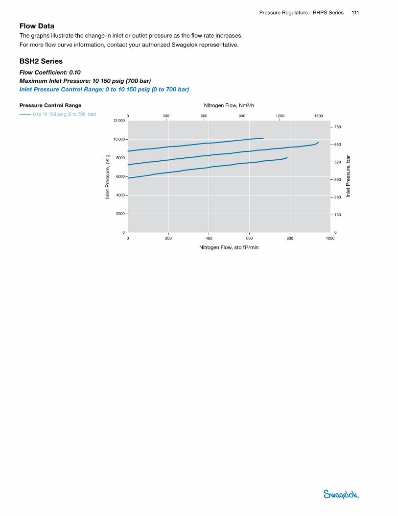
Pressure Regulators—RHPS Series 111 RHPS
REGULATORS
Flow DataThe graphs illustrate the change in inlet or outlet pressure as the flow rate increases.
For more flow curve information, contact your authorized Swagelok representative.
Nitrogen Flow, std ft3/min
Inle
t P
ress
ure,
psi
g
Inle
t P
ress
ure,
bar
Nitrogen Flow, Nm3/h
0
4000
6000
8000
10 000
12 000
2000
0 200 600400 800 1000
0 200 600400 800 1000
0 300 600 900 1200 1500
520
650
780
130
390
0
260
780
650
130
520
390
0
260
0
4000
6000
8000
10 000
12 000
2000
0 300 600 900 1200 1500
78.0
65.0
13.0
52.0
39.0
0
26.0
0 300 600 900 1200 1500
Nitrogen Flow, std ft3/min
Inle
t P
ress
ure,
psi
g
Inle
t P
ress
ure,
bar
Inle
t P
ress
ure,
psi
g
Inle
t P
ress
ure,
bar
Inle
t P
ress
ure,
MP
a
Nitrogen Flow, std ft3/min
Nitrogen Flow, Nm3/h
Nitrogen Flow, Nm3/h
Nitrogen Flow, Nm3/h
Pressure Control Range
0 to 10150 psig (0 to 700 bar)
BSH2 Series
USA
EURO
JPN
Flow Coef�cient: 0.10Maximum Inlet Pressure: BSH2—10150 psig (700 bar)Inlet Pressure Control Range: 0 to 10150 psig (0 to 700 bar)
BSH2 Series
Flow Coefficient: 0.10 Maximum Inlet Pressure: 10 150 psig (700 bar)Inlet Pressure Control Range: 0 to 10 150 psig (0 to 700 bar)
Pressure Control Range
0 to 10 150 psig (0 to 700 bar)
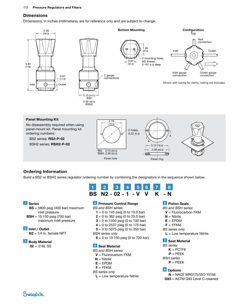
112 Pressure Regulators and FiltersRH
PS
REGU
LATO
RS
Inlet
DimensionsDimensions, in inches (millimeters), are for reference only and are subject to change.
Ordering InformationBuild a BS2 or BSH2 series regulator ordering number by combining the designators in the sequence shown below.
0.87 (22.0)
1.26 (32.0)
Outlet
2 mounting holes, M5 thread, 0.197 (5.0) deep
2.28 (58.0)
5.83 (148)
0.67 (17.0)
Bottom Mounting
Inlet Outlet
Panel hole
2 holes, 0.22 (5.5)
Panel ring
2.76 (70.0)
3.13 (79.5)
2.36 (60.0)
* A
A
2 gauge connections
ConfigurationTop
Outlet gaugeconnection
Inlet gaugeconnection
2.15 (54.5)BS2
2.30 (58.5)BSH2
Vent connection
Panel Mounting Kit
No disassembly required when using panel mount kit. Panel mounting kit ordering numbers:
BS2 series: RS2-P-02
BSH2 series: RSH2-P-02
Shown with tubing for clarity; tubing not included.
BS N2 - 02 - 1 - V V K - N2 41 3 5 6 7 8
3 Body Material 02 = 316L SS
4 Pressure Control RangeBS and BSH series 1 = 0 to 145 psig (0 to 10.0 bar) 2 = 0 to 362 psig (0 to 25.0 bar) 3 = 0 to 1450 psig (0 to 100 bar) 4 = 0 to 2537 psig (0 to 175 bar) 5 = 0 to 5075 psig (0 to 350 bar)BSH series only 6 = 0 to 10 150 psig (0 to 700 bar)
7 Seat MaterialBS series K = PCTFE P = PEEK BSH series P = PEEK
1 Series BS = 5800 psig (400 bar) maximum
inlet pressure BSH = 10 150 psig (700 bar)
maximum inlet pressure
5 Seal MaterialBS and BSH series V = Fluorocarbon FKM N = Nitrile E = EPDM F = FFKMBS series only L = Low temperature Nitrile
6 Piston SealsBS and BSH series V = Fluorocarbon FKM N = Nitrile E = EPDM F = FFKMBS series only L = Low temperature Nitrile
2 Inlet / Outlet N2 = 1/4 in. female NPT
8 Options N = NACE MR0175/ISO 15156 G93 = ASTM G93 Level C-cleaned
*BS: 2.15 (54.5)*BSH: 2.36 (60.0)

Pressure Regulators—RHPS Series 113 RHPS
REGULATORS
Features■Diaphragm sensing:
0 to 406 psig (0 to 28.0 bar)
■Piston sensing: 0 to 5220 psig (0 to 360 bar)
■Threaded vent to monitor seal integrity
Materials of Construction
General-Purpose, Spring-Loaded Back-Pressure Regulators— BS(H)4, BS(H)6, and BS(H)8 Series
Options■Antitamper
■Gauge connections —choice of 4 configurations
■NACE MR0175/ISO 15156-compliant models
■Special cleaning to ASTM G93 Level C
Technical Data
Series
Maximum Inlet
Pressurepsig (bar)
Maximum Inlet Control
Pressurepsig (bar)
Sensing Type
Temperature Range °F (°C)
Flow Coefficient
(Cv)
Seat Diameterin. (mm)
Connections Weight (Without Flanges)
lb (kg)
Inlet and Outlet Gauge and VentSize Type
BS(H)4
BS: 1015 (70.0)
BSH: 5800 (400)
BS4: 0 to 406 psig (28.0 bar) BS6, 8: 0
to 203 psig (14.0 bar)
BSH: 5220 (360)
Diaphragm: BS4: 0 to 406 psig
(28.0 bar) BS6, 8: 0 to
203 psig (14.0 bar)
Piston: 0 to 5220 psig
(360 bar)
–40 to 176 (–40 to 80)
See Pressure-
Temperature Ratings,
page 985.
BS4: 1.84BS6: 1.95BS8: 2.07
with 0.39 in. (10.0 mm) seat; All: 0.49 with
0.19 in. (5.0 mm) seat
0.39 (10.0) for up to
1160 psig (80.0 bar)
0.19 (5.0) for 2175 to
5220 psig (150 to 360 bar)
1/2 in. DN15 NPT
ISO/BSP parallel thread
ASME or EN flange
Gauge: 1/4 in. NPTVent: 1/8 in.
ISO/BSP parallel thread
7.7 (3.5)
BS(H)6 3/4 in. DN20
9.9 (4.5)
BS(H)8 1 in. DN25
BS Series Regulator with Diaphragm Sensing
and Standard Knob
BSH Series Regulator with Piston Sensing
and Antitamper Option
Component Material / Specification
Co
mm
on
Co
mp
one
nts
1 Spring housing316L SS / A479
2 Spring guide
3 Ball Commercial stainless steel
4 Set spring 302 SS / A313
5 Cap screw A4-80
6 Washer A4
7 Seat seal PCTFE or PEEK
8 Body 316L SS / A479
9 Poppet 431 SS / A276
10 O-rings EPDM, FKM, or nitrile
11 Seat 316L SS / A479
12 Overtravel spring 302 SS / A313
13 Body plug 316L SS / A479
Act
uati
on 14 Knob assembly with
adjusting screw, nuts, washers
Blue ABS with A2-70
15 Antitamper with O-ring, adjusting screw
316L SS and A2-70 (O-ring same as item 10)
Sen
sing
Mec
hani
sm
Diaphragm Only
16 Diaphragm EPDM, FKM, or nitrile
17 Diaphragm plate 316L SS / A479
18 Diaphragm screw 316L SS / A479
Piston Only
19 Piston plate316L SS / A479
20 Piston
21 Backup ring PTFE
22 Piston screw 316L SS / A479➀
Wetted lubricant: Silicone-based, synthetic hydrocarbon-based
1
14
234
5617
16
22
9
11
18
10
12
13
8
15
19
21
20
10
7 10
See pages 114 and 116 for flow data.
➀ BSH4 (range 5 and 6), BSH6 (range 6), and BSH8 (range 6) the material will be Alloy 2507.
Wetted components listed in italics. Gauge plugs (not shown): 431 SS / A276.

114 Pressure Regulators and FiltersRH
PS
REGU
LATO
RS
Flow DataThe graphs illustrate the change in inlet or outlet pressure as the flow rate increases.
For more flow curve information, contact your authorized Swagelok representative.
Nitrogen Flow, std ft3/min
Inle
t P
ress
ure,
psi
g
Inle
t P
ress
ure,
bar
Nitrogen Flow, Nm3/h
JPN
EURO
USA
0 200
0 300
800600400 1200
1200900600 1500
0 200 800600400 1200
0 5000 25 00020 00015 00010 000 30 000
0 300 1200900600 1500
500
1000
1500
2000
2500
40
80
120
160
00
0
500
1000
1500
2000
2500
40
80
120
160
0
0
1800
1800
4.0
8.0
12
16
0
1000
1000
101 (7.0)203 (14.0)
406 (28.0)
580 (40.0)580 (40.0)
1160 (80.0)1160 (80.0)
1160 (80.0)
2175 (150)
2175 (150)
2175 (150)
7,0 (101)14,0 (203)
28,0 (406)
40,0 (580)40,0 (580)
80,0 (1160)80,0 (1160)
80,0 (1160)
150 (2175)
150 (2175)
150 (2175)
0.71.4
2.8
4.04.0
8.08.0
8.0
15.0
15.0
15.0
BS(H)4 Series
Flow Coefficient: 1.84 Maximum Inlet Pressure: BS4—1015 psig (70.0 bar); BSH4—5800 psig (400 bar)
Regulator Series
BSH4 only
BS4 and BSH4
Nitrogen Flow, std ft3/min
Inle
t P
ress
ure,
psi
g
Inle
t P
ress
ure,
bar
Nitrogen Flow, Nm3/h
0
2000
3000
4000
5000
6000
1000
0 500 15001000 2000 3000
0 500 15001000 2000 3000
0 750 1500 2250 3000 4500
240
300
360
60
180
0
120
360
300
60
240
180
0
120
0
2000
3000
4000
5000
6000
1000
0 750 1500 2250 3000 3750
2500
3750
4500
2500
36.0
30.0
6.0
24.0
18.0
0
12.0
0 750 1500 2250 3000 3750 4500
Nitrogen Flow, std ft3/min
Inle
t P
ress
ure,
psi
g
Inle
t P
ress
ure,
bar
Inle
t P
ress
ure,
psi
g
Inle
t P
ress
ure,
bar
Inle
t P
ress
ure,
MP
a
Nitrogen Flow, std ft3/min
Nitrogen Flow, Nm3/h
Nitrogen Flow, Nm3/h
Nitrogen Flow, Nm3/h
Pressure Control Range
0 to 5220 psig (0 to 360 bar)
BSH4 Series
USA
EURO
JPN
Flow Coef�cient: 0.49Maximum Inlet Pressure: BSH4—5800 psig (400 bar)Inlet Pressure Control Range: 0 to 5220 psig (0 to 360 bar)
BSH4 Series
Flow Coefficient: 0.49 Maximum Inlet Pressure: 5800 psig (400 bar)Inlet Pressure Control Range: 0 to 5220 psig (0 to 360 bar)
Pressure Control Range
0 to 5220 psig (360 bar)

Pressure Regulators—RHPS Series 115 RHPS
REGULATORS
BS(H)6 Series
JPN
EURO
USA
0 200
0 400
800600400 1400
16001200800 2000
0 200 800600400 1400
0 5000 25 00020 00015 00010 000 30 000
0 400 16001200800
500
1000
1500
2000
2500
75
100
125
150
00
0
500
1000
1500
2000
2500
75
100
125
150
0
0
2000
0
1000
1000
50
25
50
25
7.5
10.0
12.5
15.0
5.0
2.5
1200
1200
35 000
101 (7.0)203 (14.0)
406 (28.0)
580 (40.0)
1160 (80.0)
2175 (150)
2175 (150)
2175 (150)
1160 (80.0)
1160 (80.0)
580 (40.0)
7,0 (101)14,0 (203)
28,0 (406)
40,0 (580)
80,0 (1160)
150 (2175)
150 (2175)
150 (2175)
80,0 (1160)
80,0 (1160)
40,0 (580)
0.71.4
2.8
4.0
8.0
15.0
15.0
15.0
8.0
8.0
4.0
Nitrogen Flow, std ft3/min
Inle
t P
ress
ure,
psi
g
Inle
t P
ress
ure,
bar
Nitrogen Flow, Nm3/h
Flow Coefficient:1.95 Maximum Inlet Pressure: BS6—1015 psig (70.0 bar); BSH6—5800 psig (400 bar)
Regulator Series
BSH6 only
BS6 and BSH6
Flow DataThe graphs illustrate the change in inlet or outlet pressure as the flow rate increases.
For more flow curve information, contact your authorized Swagelok representative.
Nitrogen Flow, std ft3/min
Inle
t P
ress
ure,
psi
g
Inle
t P
ress
ure,
bar
Nitrogen Flow, Nm3/h
0
2000
3000
4000
5000
6000
1000
0 500 15001000 2000 3000
0 500 15001000 2000 3000
0 750 1500 2250 3000 4500
240
300
360
60
180
0
120
360
300
60
240
180
0
120
0
2000
3000
4000
5000
6000
1000
0 750 1500 2250 3000 3750
2500
3750
4500
2500
36.0
30.0
6.0
24.0
18.0
0
12.0
0 750 1500 2250 3000 3750 4500
Nitrogen Flow, std ft3/min
Inle
t P
ress
ure,
psi
g
Inle
t P
ress
ure,
bar
Inle
t P
ress
ure,
psi
g
Inle
t P
ress
ure,
bar
Inle
t P
ress
ure,
MP
a
Nitrogen Flow, std ft3/min
Nitrogen Flow, Nm3/h
Nitrogen Flow, Nm3/h
Nitrogen Flow, Nm3/h
Pressure Control Range
0 to 5220 psig (0 to 360 bar)
BSH6 Series
USA
EURO
JPN
Flow Coef�cient: 0.49Maximum Inlet Pressure: BSH6—5800 psig (400 bar)Inlet Pressure Control Range: 0 to 5220 psig (0 to 360 bar)
BSH6 Series
Flow Coefficient: 0.49 Maximum Inlet Pressure: 5800 psig (400 bar)Inlet Pressure Control Range: 0 to 5220 psig (0 to 360 bar)
Pressure Control Range
0 to 5220 psig (360 bar)

116 Pressure Regulators and FiltersRH
PS
REGU
LATO
RS
Flow DataThe graphs illustrate the change in inlet or outlet pressure as the flow rate increases.
For more flow curve information, contact your authorized Swagelok representative.
JPN
EURO
USA
0 200
0 300
800600400 1200
1200900600 1500
0 200 800600400 1200
0 5000 25 00020 00015 00010 000 30 000
0 300 1200900600 1500
500
1000
1500
2000
2500
40
80
120
160
00
0
500
1000
1500
2000
2500
40
80
120
160
0
0
1800
1800
4.0
8.0
12
16
0
1000
1000
101 (7.0)203 (14.0)
406 (28.0)
580 (40.0)
43 (3.0)
406 (28.0)
1160 (80.0)1160 (80.0)1160 (80.0)
2175 (150)
2175 (150)
2175 (150)
150 (2175)
150 (2175)
150 (2175)
80,0 (1160)
80,0 (1160)80,0 (1160)
7,0 (101)14,0 (203)
28,0 (406)40,0 (580)
28,0 (406)
3,0 (43)
0.30.71.4
2.84.0
8.0
15.0
15.0
15.0
8.08.0
2.8
BS(H)8 Series
Nitrogen Flow, std ft3/min
Inle
t P
ress
ure,
psi
g
Inle
t P
ress
ure,
bar
Nitrogen Flow, Nm3/h
Flow Coefficient: 2.07 Maximum Inlet Pressure: BS8—1015 psig (70.0 bar); BSH8—5800 psig (400 bar)
Regulator Series
BSH8 only
BS8 and BSH8
Nitrogen Flow, std ft3/min
Inle
t P
ress
ure,
psi
g
Inle
t P
ress
ure,
bar
Nitrogen Flow, Nm3/h
0
2000
3000
4000
5000
6000
1000
0 500 15001000 2000 3000
0 500 15001000 2000 3000
0 750 1500 2250 3000 4500
240
300
360
60
180
0
120
360
300
60
240
180
0
120
0
2000
3000
4000
5000
6000
1000
0 750 1500 2250 3000 3750
2500
3750
4500
2500
36.0
30.0
6.0
24.0
18.0
0
12.0
0 750 1500 2250 3000 3750 4500
Nitrogen Flow, std ft3/min
Inle
t P
ress
ure,
psi
g
Inle
t P
ress
ure,
bar
Inle
t P
ress
ure,
psi
g
Inle
t P
ress
ure,
bar
Inle
t P
ress
ure,
MP
a
Nitrogen Flow, std ft3/min
Nitrogen Flow, Nm3/h
Nitrogen Flow, Nm3/h
Nitrogen Flow, Nm3/h
Pressure Control Range
0 to 5220 psig (0 to 360 bar)
BSH8 Series
USA
EURO
JPN
Flow Coef�cient: 0.49Maximum Inlet Pressure: BSH8—5800 psig (400 bar)Inlet Pressure Control Range: 0 to 5220 psig (0 to 360 bar)
BSH8 Series
Flow Coefficient: 0.49 Maximum Inlet Pressure: 5800 psig (400 bar)Inlet Pressure Control Range: 0 to 5220 psig (0 to 360 bar)
Pressure Control Range
0 to 5220 psig (360 bar)

Pressure Regulators—RHPS Series 117 RHPS
REGULATORS
RS4 only RS6 and 8 only
4 mounting holes, M6 thread
DimensionsDimensions, in inches (millimeters), are for reference only and are subject to change.
Series
End Connection
Size
Dimensions, in. (mm)
A B C D E
BS(H)4 1/2 in. 9.06 (230) 2.83 (72.0) 3.07 (78.0) 2.09 (53.0) 3.62 (92.0)
BS(H)6 3/4 in. 9.25 (235) 3.23 (82.0) 3.50 (89.0) 2.20 (56.0) 3.94 (100)
BS(H)8 1 in. 9.25 (235) 3.07 (78.0) 3.50 (89.0) 2.20 (56.0) 3.94 (100)
Ordering InformationBuild a BS(H)4, BS(H)6, and BS(H)8 series regulator ordering number by combining the designators in the sequence shown below.
RS4 only RS6 and 8 onlyRS4 only RS6 and 8 only
Panel MountingBS(H)4 only
A
B
D
C
E
Threaded vent connection
1.10 (28.0)
1.10 (28.0)
0.67 (17.0)
0.67 (17.0)
RS4 only RS6 and 8 only
Inlet Outlet
Configuration Top Gauge
connection
Shown with tubing for clarity; tubing not included.
Inlet gauge connection
Inlet gauge connection
Inlet Outlet
2.72 (69.2)
6 Body Material 02 = 316L SS
7 Pressure Control RangeDiaphragm sensing 1 = 0 to 43 psig (0 to 3.0 bar) 2 = 0 to 101 psig (0 to 7.0 bar) 3 = 0 to 203 psig (0 to 14.0 bar) 4 = 0 to 406 psig (0 to 28.0 bar)➀Piston sensing 4 = 0 to 406 psig (0 to 28.0 bar)➁ 5 = 0 to 580 psig (0 to 40.0 bar) 6 = 0 to 1160 psig (0 to 80.0 bar) 7 = 0 to 2175 psig (0 to 150 bar) 9 = 0 to 4060 psig (0 to 280 bar) 11 = 0 to 5220 psig (0 to 360 bar)➀ BS(H)4 series only.➁ BS(H)6 and BS(H)8 series only.
10 Seat Seal Material K = PCTFE P = PEEK
1 Series BS = 1015 psig (70.0 bar) maximum
inlet pressure BSH = 5800 psig (400 bar) maximum
inlet pressure
8 Seal Material V = Fluorocarbon FKM N = Nitrile E = EPDM L = Low temperature Nitrile
9 Diaphragm / Piston O-Rings V = Fluorocarbon FKM N = Nitrile E = EPDM L = Low temperature Nitrile
5 Flange Facing Omit designator if flanges are not ordered.
1 = Raised face smooth 3 = RTJ
BS FA 4 A 1 - 02 - 1 - V V K - GN22 41 3 5 6 7 8 9 10 11
2 Inlet / Outlet B = Female ISO/BSP parallel thread N = Female NPT FA = ASME B16.5 flange FD = EN 1092 (DIN) flange
11 Options A = Antitamper GN1 = Gauge connection, see below GN2 = Gauge connection, see below GN5 = Gauge connection, see belowNone = Standard connection, see below
Gauge Connection Configuration
Standard GN1 GN2 GN5
Go GiGoGo Gi Go
Gi Gi GoGi Gi Go
Gi Go GiGi Gi Go
std
Pressure reducing
Back Pressure
std
N = NACE MR0175/ISO 15156 G93 = ASTM G93 Level C-cleaned
4 Pressure Class Omit designator if flanges are not ordered.
A = ASME class 150 B = ASME class 300 C = ASME class 600 E = ASME class 1500 F = ASME class 2500 M = EN class PN16 N = EN class PN40
3 Size 4 = 1/2 in. / DN15 6 = 3/4 in. / DN20 8 = 1 in. / DN25
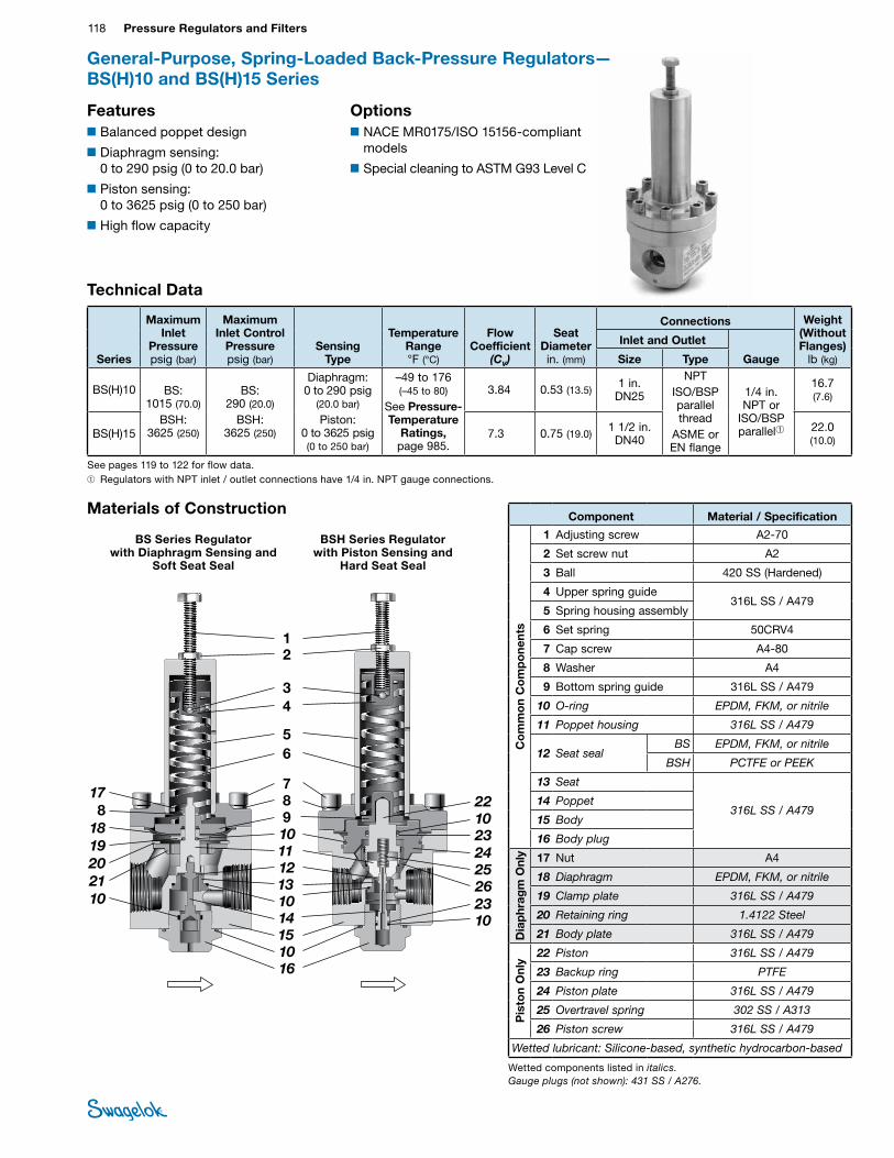
118 Pressure Regulators and FiltersRH
PS
REGU
LATO
RS
Features■Balanced poppet design
■Diaphragm sensing: 0 to 290 psig (0 to 20.0 bar)
■Piston sensing: 0 to 3625 psig (0 to 250 bar)
■High flow capacity
General-Purpose, Spring-Loaded Back-Pressure Regulators— BS(H)10 and BS(H)15 Series
Technical Data
Series
Maximum Inlet
Pressurepsig (bar)
Maximum Inlet Control
Pressurepsig (bar)
Sensing Type
Temperature Range °F (°C)
Flow Coefficient
(Cv)
Seat Diameterin. (mm)
Connections Weight (Without Flanges)
lb (kg)
Inlet and Outlet
GaugeSize Type
BS(H)10 BS: 1015 (70.0)
BSH: 3625 (250)
BS: 290 (20.0)
BSH: 3625 (250)
Diaphragm: 0 to 290 psig
(20.0 bar)
Piston: 0 to 3625 psig (0 to 250 bar)
–49 to 176 (–45 to 80)
See Pressure-Temperature
Ratings, page 985.
3.84 0.53 (13.5)1 in.
DN25
NPTISO/BSP parallel thread
ASME or EN flange
1/4 in. NPT or
ISO/BSP parallel➀
16.7 (7.6)
BS(H)15 7.3 0.75 (19.0)1 1/2 in.
DN4022.0 (10.0)
Options■NACE MR0175/ISO 15156-compliant
models
■Special cleaning to ASTM G93 Level C
➀ Regulators with NPT inlet / outlet connections have 1/4 in. NPT gauge connections.
Materials of Construction
BS Series Regulator with Diaphragm Sensing and
Soft Seat Seal
BSH Series Regulator with Piston Sensing and
Hard Seat Seal
Component Material / SpecificationC
om
mo
n C
om
po
nent
s1 Adjusting screw A2-70
2 Set screw nut A2
3 Ball 420 SS (Hardened)
4 Upper spring guide316L SS / A479
5 Spring housing assembly
6 Set spring 50CRV4
7 Cap screw A4-80
8 Washer A4
9 Bottom spring guide 316L SS / A479
10 O-ring EPDM, FKM, or nitrile
11 Poppet housing 316L SS / A479
12 Seat sealBS EPDM, FKM, or nitrile
BSH PCTFE or PEEK
13 Seat
316L SS / A47914 Poppet
15 Body
16 Body plug
Dia
phr
agm
Onl
y 17 Nut A4
18 Diaphragm EPDM, FKM, or nitrile
19 Clamp plate 316L SS / A479
20 Retaining ring 1.4122 Steel
21 Body plate 316L SS / A479
Pis
ton
Onl
y
22 Piston 316L SS / A479
23 Backup ring PTFE
24 Piston plate 316L SS / A479
25 Overtravel spring 302 SS / A313
26 Piston screw 316L SS / A479
Wetted lubricant: Silicone-based, synthetic hydrocarbon-based
12
34
56
7
13
1110
8
10
12
22
151016
14
17
18
2021
10
24
26
23
25
98
2310
10
19
Wetted components listed in italics. Gauge plugs (not shown): 431 SS / A276.
See pages 119 to 122 for flow data.

Pressure Regulators—RHPS Series 119 RHPS
REGULATORS
Flow DataThe graphs illustrate the change in inlet or outlet pressure as the flow rate increases.
For more flow curve information, contact your authorized Swagelok representative.
BS10 Series
Pressure Control Range
0 to 290 psig (0 to 20.0 bar)
0 to 145 psig (0 to 10.0 bar)
0 to 72 psig (0 to 5.0 bar)
0 to 43 psig (0 to 3.0 bar)
Nitrogen Flow, std ft3/min
Inle
t P
ress
ure,
psi
g
Inle
t P
ress
ure,
bar
Nitrogen Flow, Nm3/h
0
160
240
320
400
80
0 200 600400 800 1000
0 200 600400 800 1000
0 300 600 900 1200 1500
15
20
25
10
0
5
25
20
15
10
0
5
0
80
160
240
320
400
0 300 600 900 1200 1500
2.5
2.0
1.5
1.0
0
0.5
0 300 600 900 1200 1500
Nitrogen Flow, std ft3/min
Inle
t P
ress
ure,
psi
g
Inle
t P
ress
ure,
bar
Inle
t P
ress
ure,
psi
gIn
let
Pre
ssur
e, p
sig
Inle
t P
ress
ure,
bar
Nitrogen Flow, std ft3/min
Nitrogen Flow, Nm3/h
Nitrogen Flow, Nm3/h
Nitrogen Flow, Nm3/h
Pressure Control Range
0 to 72 psig (0 to 5.0 bar)
0 to 145 psig (0 to 10.0 bar)
0 to 290 psig (0 to 20.0 bar)
BS10 Series
0 to 43 psig (0 to 3.0 bar) USA
EURO
JPN
Flow Coef�cient: 3.84Maximum Inlet Pressure: BS10—1015 psig (70 bar)Inlet Pressure Control Range: 0 to 290 psig (0 to 20.0 bar)
Flow Coefficient: 3.84 Maximum Inlet Pressure: 1015 psig (70 bar)Inlet Pressure Control Range: 0 to 290 psig (0 to 20.0 bar)

120 Pressure Regulators and FiltersRH
PS
REGU
LATO
RS
Flow DataThe graphs illustrate the change in inlet or outlet pressure as the flow rate increases.
For more flow curve information, contact your authorized Swagelok representative.
Nitrogen Flow, std ft3/min
Inle
t P
ress
ure,
psi
g
Inle
t P
ress
ure,
bar
Nitrogen Flow, Nm3/h
0
1600
2400
3200
4000
800
0 1600 48003200 6400 8000
0 1600 48003200 6400 8000
0 2400 4800 7200 9600 12 000
150
200
250
100
0
50
250
200
150
100
0
50
0
800
1600
2400
3200
4000
0 2400 4800 7200 9600 12 000
25.0
20.0
15.0
10.0
0
5.0
0 2400 4800 7200 9600 12 000
Nitrogen Flow, std ft3/min
Inle
t P
ress
ure,
psi
g
Inle
t P
ress
ure,
bar
Inle
t P
ress
ure,
psi
gIn
let
Pre
ssur
e, p
sig
Inle
t P
ress
ure,
bar
Nitrogen Flow, std ft3/min
Nitrogen Flow, Nm3/h
Nitrogen Flow, Nm3/h
Nitrogen Flow, Nm3/h
Pressure Control Range
0 to 3625 psig (0 to 250 bar)
BSH10 Series
0 to 2610 psig (0 to 180 bar)
USA
EURO
JPN
Flow Coef�cient: 3.84Maximum Inlet Pressure: BSH10—3625 psig (250 bar)Inlet Pressure Control Range: 0 to 3625 psig (0 to 250 bar)
BSH10 Series
Flow Coefficient: 3.84 Maximum Inlet Pressure: 3625 psig (250 bar)Inlet Pressure Control Range: 0 to 3625 psig (0 to 250 bar)
Pressure Control Range
0 to 3625 psig (0 to 250 bar)
0 to 2610 psig (0 to 180 bar)
Nitrogen Flow, std ft3/min
Inle
t P
ress
ure,
psi
g
Inle
t P
ress
ure,
bar
Nitrogen Flow, Nm3/h
0
800
1200
1600
2000
400
0 800 24001600 3200 4000
0 800 24001600 3200 4000
0 600 1200 1800 2400 3000
150
200
250
100
0
50
250
200
150
100
0
50
0
400
800
1200
1600
2000
0 600 1200 1800 2400 3000
25.0
20.0
15.0
10.0
0
5.0
0 600 1200 1800 2400 3000
Nitrogen Flow, std ft3/min
Inle
t P
ress
ure,
psi
g
Inle
t P
ress
ure,
bar
Inle
t P
ress
ure,
psi
gIn
let
Pre
ssur
e, p
sig
Inle
t P
ress
ure,
bar
Nitrogen Flow, std ft3/min
Nitrogen Flow, Nm3/h
Nitrogen Flow, Nm3/h
Nitrogen Flow, Nm3/h
Pressure Control Range
0 to 1450 psig (0 to 100 bar)
BSH10 Series
0 to 580 psig (0 to 40.0 bar)
USA
EURO
JPN
Flow Coef�cient: 3.84Maximum Inlet Pressure: BSH10—3625 psig (250 bar)Inlet Pressure Control Range: 0 to 1450 psig (0 to 100 bar)
BSH10 Series
Flow Coefficient: 3.84 Maximum Inlet Pressure: 3625 psig (250 bar)Inlet Pressure Control Range: 0 to 1450 psig (0 to 100 bar)
Pressure Control Range
0 to 1450 psig (0 to 100 bar)
0 to 580 psig (0 to 40.0 bar)

Pressure Regulators—RHPS Series 121 RHPS
REGULATORS
Flow DataThe graphs illustrate the change in inlet or outlet pressure as the flow rate increases.
For more flow curve information, contact your authorized Swagelok representative.
BS15 Series
Pressure Control Range
0 to 290 psig (0 to 20.0 bar)
0 to 145 psig (0 to 10.0 bar)
0 to 72 psig (0 to 5.0 bar)
0 to 43 psig (0 to 3.0 bar)
Nitrogen Flow, std ft3/min
Inle
t P
ress
ure,
psi
g
Inle
t P
ress
ure,
bar
Nitrogen Flow, Nm3/h
0
90
180
270
360
450
0 500 15001000 2000 3000
0 500 15001000 2000 3000
0 750 1500 2250 3000 4500
24
30
6
18
0
12
30
24
6
18
12
0 0
180
270
360
450
90
0 750 1500 2250 3000 3750
2500
3750
4500
2500
3.0
2.4
0.6
1.8
1.2
00 750 1500 2250 3000 3750 4500
Nitrogen Flow, std ft3/min
Inle
t P
ress
ure,
psi
g
Inle
t P
ress
ure,
bar
Inle
t P
ress
ure,
psi
g
Inle
t P
ress
ure,
bar
Inle
t P
ress
ure,
MP
a
Nitrogen Flow, std ft3/min
Nitrogen Flow, Nm3/h
Nitrogen Flow, Nm3/h
Nitrogen Flow, Nm3/h
Pressure Control Range
0 to 290 psig (0 to 20.0 bar)
BS15 Series
0 to 43 psig (0 to 3.0 bar)
0 to 72 psig (0 to 5.0 bar)
0 to 145 psig (0 to 10.0 bar)
USA
EURO
JPN
Flow Coef�cient: 7.3Maximum Inlet Pressure: BS15—1015 psig (70 bar)Inlet Pressure Control Range: 0 to 290 psig (0 to 20.0 bar)
Flow Coefficient: 7.3 Maximum Inlet Pressure: 1015 psig (70 bar)Inlet Pressure Control Range: 0 to 290 psig (0 to 20.0 bar)

122 Pressure Regulators and FiltersRH
PS
REGU
LATO
RS
Flow DataThe graphs illustrate the change in inlet or outlet pressure as the flow rate increases.
For more flow curve information, contact your authorized Swagelok representative.
Nitrogen Flow, std ft3/min
Inle
t P
ress
ure,
psi
g
Inle
t P
ress
ure,
bar
Nitrogen Flow, Nm3/h
0
1600
2400
3200
4000
800
0 4000 12 0008000 16 000 20 000
0 4000 12 0008000 16 000 20 000
0 6000 12 000 18 000 24 000 30 000
150
200
250
100
0
50
250
200
150
100
0
50
0
800
1600
2400
3200
4000
0 6000 12 000 18 000 24000 30 000
25.0
20.0
15.0
10.0
0
5.0
0 6000 12 000 18 000 24000 30 000
Nitrogen Flow, std ft3/min
Inle
t P
ress
ure,
psi
g
Inle
t P
ress
ure,
bar
Inle
t P
ress
ure,
psi
gIn
let
Pre
ssur
e, p
sig
Inle
t P
ress
ure,
bar
Nitrogen Flow, std ft3/min
Nitrogen Flow, Nm3/h
Nitrogen Flow, Nm3/h
Nitrogen Flow, Nm3/h
Pressure Control Range
0 to 3625 psig (0 to 250 bar)
BSH15 Series
0 to 2610 psig (0 to 180 bar)
USA
EURO
JPN
Flow Coef�cient: 7.3Maximum Inlet Pressure: BSH15—3625 psig (250 bar)Inlet Pressure Control Range: 0 to 3625 psig (0 to 250 bar)
BSH15 Series
Flow Coefficient: 7.3 Maximum Inlet Pressure: 3625 psig (250 bar)Inlet Pressure Control Range: 0 to 3625 psig (0 to 250 bar)
Pressure Control Range
0 to 3625 psig (0 to 250 bar)
0 to 2610 psig (0 to 180 bar)
Nitrogen Flow, std ft3/min
Inle
t P
ress
ure,
psi
g
Inle
t P
ress
ure,
bar
Nitrogen Flow, Nm3/h
0
800
1200
1600
2000
400
0 2000 60004000 8000 10 000
0 2000 60004000 8000 10 000
0 3000 6000 9000 12 000 15 000
75
100
125
50
0
25
125
100
75
50
0
25
0
400
800
1200
1600
2000
0 3000 6000 9000 12 000 15 000
12.5
10.0
7.5
5.0
0
2.5
0 3000 6000 9000 12 000 15 000
Nitrogen Flow, std ft3/min
Inle
t P
ress
ure,
psi
g
Inle
t P
ress
ure,
bar
Inle
t P
ress
ure,
psi
gIn
let
Pre
ssur
e, p
sig
Inle
t P
ress
ure,
bar
Nitrogen Flow, std ft3/min
Nitrogen Flow, Nm3/h
Nitrogen Flow, Nm3/h
Nitrogen Flow, Nm3/h
Pressure Control Range
0 to 1450 psig (0 to 100 bar)
BSH15 Series
0 to 580 psig (0 to 40.0 bar)
USA
EURO
JPN
Flow Coef�cient: 7.3Maximum Inlet Pressure: BSH15—3625 psig (250 bar)Inlet Pressure Control Range: 0 to 1450 psig (0 to 100 bar)
BSH15 Series
Flow Coefficient: 7.3 Maximum Inlet Pressure: 3625 psig (250 bar)Inlet Pressure Control Range: 0 to 1450 psig (0 to 100 bar)
Pressure Control Range
0 to 1450 psig (0 to 100 bar)
0 to 580 psig (0 to 40.0 bar)

Pressure Regulators—RHPS Series 123 RHPS
REGULATORS
DimensionsDimensions, in inches (millimeters), are for reference only and are subject to change.
Series
End Connection
Size
Dimensions, in. (mm)
A B C D E F
BS(H)10 1 in. 10.5 (266) 3.54 (90.0) 3.07 (78.0) 2.28 (58.0) 1.97 (50.0) 1.77 (45.0)
BS(H)15 1 1/2 in. 10.8 (275) 4.53 (115) 3.78 (96.0) 2.44 (62.0) 2.01 (51.0) 1.77 (45.0)
Ordering InformationBuild a BS(H)10 and BS(H)15 series regulator ordering number by combining the designators in the sequence shown below.
A
B C
DE
4.53 (115)
FInlet Outlet
2 gauge connections
Configuration Top
Inlet gauge connection
Shown with tubing for clarity; tubing not included.
Outlet gauge connection
1.97 (50.0)
Inlet Outlet
4.53 (115)
6 Body Material 02 = 316L SS
7 Pressure Control RangeDiaphragm sensing (BS series only) 1 = 0 to 43 psig (0 to 3.0 bar) 2 = 0 to 72 psig (0 to 5.0 bar) 3 = 0 to 145 psig (0 to 10.0 bar) 4 = 0 to 290 psig (0 to 20.0 bar)Piston sensing (BSH series only) 5 = 0 to 580 psig (0 to 40.0 bar) 6 = 0 to 1450 psig (0 to 100 bar) 7 = 0 to 2610 psig (0 to 180 bar) 8 = 0 to 3625 psig (0 to 250 bar)
10 Seat Seal MaterialBS series V = Fluorocarbon FKM N = Nitrile E = EPDM L = Low temperature NitrileBSH series K = PCTFE P = PEEK
1 Series BS = 1015 psig (70.0 bar) maximum
inlet pressure BSH = 3625 psig (250 bar) maximum
inlet pressure
8 Seal Material V = Fluorocarbon FKM N = Nitrile E = EPDM L = Low temperature Nitrile
9 Diaphragm / Piston O-Rings V = Fluorocarbon FKM N = Nitrile E = EPDM L = Low temperature Nitrile
5 Flange Facing Omit designator if flanges are not ordered.
1 = Raised face smooth 3 = RTJ
BS FA 10 A 1 - 02 - 1 - V V V - N2 41 3 5 6 7 8 9 10 11
2 Inlet / Outlet B = Female ISO/BSP parallel thread N = Female NPT FA = ASME B16.5 flange FD = EN 1092 (DIN) flange
11 Options N = NACE MR0175/ISO 15156 G93 = ASTM G93 Level C-cleaned
4 Pressure Class Omit designator if flanges are not ordered.
A = ASME class 150 B = ASME class 300 C = ASME class 600 E = ASME class 1500 F = ASME class 2500 M = EN class PN16 N = EN class PN40
3 Size 10 = 1 in. / DN25 15 = 1 1/2 in. / DN40
Only one gauge with a 50 mm (2 in.) or larger
dial size fits directly into the body.
Gauge Connection

124 Pressure Regulators and FiltersRH
PS
REGU
LATO
RS
Features■Diaphragm sensing
■Bottom mounting and panel mounting
High-Sensitivity, Spring-Loaded Back-Pressure Regulators— LBS4 Series
Options■NACE MR0175/ISO 15156-compliant
model
■Special cleaning to ASTM G93 Level C
Technical Data
Series
Maximum Inlet
Pressurepsig (bar)
Maximum Inlet Control Pressure➀psig (bar)
Sensing Type
Temperature Range °F (°C)
Flow Coefficient
(Cv)
Seat Diameterin. (mm)
Inlet and Outlet
ConnectionGauge
ConnectionWeightlb (kg)
LBS4 507 (35.0) 290 (20.0) Diaphragm
–49 to 176 (–45 to 80)
See Pressure-Temperature
Ratings, page 985.
1.3 0.31 (8.0) 1/2 in. NPT 1/4 in. NPT 5.7 (2.6)
See pages 125 and 126 for flow data.
Materials of Construction
LBS Series Regulator with Soft SeatComponent Material / Specification
1 Knob assembly with adjusting screw, nuts Blue ABS with 431 SS
2 Spring housing cover316L SS / A479
3 Spring housing
4 C-ring A2
5 Spring guide 316L SS / A479
6 Set spring 50CRV4
7 Cap screw A4-80
8 Washer A2
9 Bottom spring guide316L SS / A479
10 Clamp ring
11 Diaphragm PTFE or 316L SS
12 Body
316L SS / A47913 Seat retainer
14 Poppet housing
15 Seat seal FKM, FFKM, EPDM, or nitrile
16 O-ring PTFE
17 Seat 316L SS / A479
18 Poppet 431 SS / A276
Wetted lubricants: Silicone-based, synthetic hydrocarbon-based
23
10
9
1
45
67
12
8
13
111514
1716
18
Wetted components listed in italics. Gauge plugs (not shown): 431 SS / A276.
➀ Maximum inlet control pressure limited to 130 psig (9.0 bar) for regulators built with 316SS diaphragms.

Pressure Regulators—RHPS Series 125 RHPS
REGULATORS
Flow DataThe graphs illustrate the change in inlet or outlet pressure as the flow rate increases.
For more flow curve information, contact your authorized Swagelok representative.
Nitrogen Flow, std ft3/min
Inle
t P
ress
ure,
psi
g
Inle
t P
ress
ure,
bar
Nitrogen Flow, Nm3/h
JPN
EURO
USA
0 50 200150100 250 300
0 50 200150100 250 300
0
100
200
300
400
4.0
16
20
24
0
0
100
200
300
400
4,0
16
20
24
0
40002000 60000
8000
0 75 225150 300 375
0 75 225150 300 375
450
450
12
8.0
12
8,0
0.4
1.6
2.4
1.2
0.8
2.0
0
LBS4 Series
LBS4 Series
JPN
EURO
USA
0 10 403020 50 60
0 10 403020 50 60
0
10
20
30
40
50
60
1.0
2.0
3.0
4.0
0
0
10
20
30
40
50
60
1,0
2,0
3,0
4,0
0
800400 1200
0.1
0.2
0.3
0.4
01600
0 15 4530 60 75
0 15 4530 60 75
90
90
0
Nitrogen Flow, std ft3/min
Inle
t P
ress
ure,
psi
g
Inle
t P
ress
ure,
bar
Nitrogen Flow, Nm3/h Pressure Control Range
0 to 43 psig (0 to 3.0 bar)
Flow Coefficient: 1.3 Maximum Inlet Pressure: 507 psig (35.0 bar)Inlet Pressure Control Range: 0 to 43 psig (0 to 3.0 bar)
Flow Coefficient: 1.3 Maximum Inlet Pressure: 507 psig (35.0 bar)Inlet Pressure Control Range: 0 to 290 psig (0 to 20.0 bar)
Pressure Control Range
0 to 130 psig (0 to 9.0 bar)
0 to 290 psig (0 to 20.0 bar)

126 Pressure Regulators and FiltersRH
PS
REGU
LATO
RS
Flow DataThe graphs illustrate the change in inlet or outlet pressure as the flow rate increases.
For more flow curve information, contact your authorized Swagelok representative.
Nitrogen Flow, std ft3/min
Inle
t P
ress
ure,
psi
g
Inle
t P
ress
ure,
bar
Nitrogen Flow, Nm3/h
0
100
150
200
250
300
50
0 20 6040 80 120
0 20 6040 80 120
0 30 60 90 120 180
12
15
18
3
9
0
6
18
15
3
12
9
0
6
0
100
150
200
250
300
50
0 30 60 90 120 150
100
150
180
100
1.8
1.5
0.3
1.2
0.9
0
0.6
0 30 60 90 120 150 180
Nitrogen Flow, std ft3/min
Inle
t P
ress
ure,
psi
g
Inle
t P
ress
ure,
bar
Inle
t P
ress
ure,
psi
g
Inle
t P
ress
ure,
bar
Inle
t P
ress
ure,
MP
a
Nitrogen Flow, std ft3/min
Nitrogen Flow, Nm3/h
Nitrogen Flow, Nm3/h
Nitrogen Flow, Nm3/h
Pressure Control Range
0 to 130 psig (0 to 9 bar)
LBS4 with Metal Diaphragm
USA
EURO
JPN
Flow Coef�cient: 1.3Maximum Inlet Pressure: LBS4—507 psig (35.0 bar)Inlet Pressure Control Range: 0 to 130 psig (0 to 9 bar)
LBS4 Series
LBS4 Series
0
40
60
80
100
120
20
0 10 3020 40 50
0 10 3020 40 50
0 15 30 45 60 75
4.8
6.0
7.2
1.2
3.6
0
2.4
7.2
6.0
1.2
4.8
3.6
0
2.4
0
40
60
80
100
120
20
0 15 30 45 60 75
0.72
0.60
0.12
0.48
0.36
0
0.24
0 15 30 45 60 75
Nitrogen Flow, std ft3/min
Inle
t P
ress
ure,
psi
g
Inle
t P
ress
ure,
bar
Inle
t P
ress
ure,
psi
g
Inle
t P
ress
ure,
bar
Inle
t P
ress
ure,
MP
a
Nitrogen Flow, std ft3/min
Nitrogen Flow, Nm3/h
Nitrogen Flow, Nm3/h
Nitrogen Flow, Nm3/h
Pressure Control Range
0 to 43 psig (0 to 3 bar)
LBS4 with Metal Diaphragm
USA
EURO
JPN
Flow Coef�cient: 1.3Maximum Inlet Pressure: LBS4—507 psig (35.0 bar)Inlet Pressure Control Range: 0 to 43 psig (0 to 3.0 bar)
Nitrogen Flow, std ft3/min
Inle
t P
ress
ure,
psi
g
Inle
t P
ress
ure,
bar
Nitrogen Flow, Nm3/h Pressure Control Range
0 to 43 psig (0 to 3.0 bar)
Flow Coefficient: 1.3 Maximum Inlet Pressure: 507 psig (35.0 bar)Inlet Pressure Control Range: 0 to 43 psig (0 to 3.0 bar)
Flow Coefficient: 1.3 Maximum Inlet Pressure: 507 psig (35.0 bar)Inlet Pressure Control Range: 0 to 130 psig (0 to 9.0 bar)
Pressure Control Range
0 to 130 psig (0 to 9.0 bar)
Optional 316L SS Diapragmh
Optional 316L SS Diapragmh

Pressure Regulators—RHPS Series 127 RHPS
REGULATORS
BAR BAR
DimensionsDimensions, in inches (millimeters), are for reference only and are subject to change.
Panel Mounting Bottom Mounting
2.28 (58.0)
6.54 (166)
2.48 (63.0)
3.52 (89.5)
2.83 (72.0)
0.75 (19.0)
0.83 (21.0) 1.42
(36.0) 1.76 (44.7)
3.52 (89.5)
Vent connection
2.83 (72.0)
1.18 (30.0)
4 mounting holes M6 thread, 0.39 (10.0) deep
Panel hole: 2.40 (61.0)
3.03 (77.0)
2 gauge connections
Inlet Outlet
ConfigurationTop
Inlet gauge connection
Inlet gauge connection
Shown with tubing for clarity; tubing not included.
2 mounting holes for M5 × 20 screws
Inlet Outlet
Ordering InformationBuild an LBS4 series regulator ordering number by combining the designators in the sequence shown below.
LBS N4 - 02 - 1 - T T V - N2 41 3 5 6 7 8
3 Body Material 02 = 316L SS
4 Pressure Control Range 1 = 0 to 43 psig (0 to 3.0 bar) 2 = 0 to 130 psig (0 to 9.0 bar) 3 = 0 to 290 psig (0 to 20.0 bar)
7 Seat Seal Material V = Fluorocarbon FKM N = Nitrile E = EPDM F = FFKM L = Low temperature Nitrile
1 Series LBS = 507 psig (35.0 bar) maximum
inlet pressure
5 Seal Material T = PTFE L = Low temperature Nitrile
6 Diaphragm T = PTFE➀
M = 316L SS: only for 0 to 43 psig (0 to 3.0 bar) and 0 to 130 psig (0 to 9.0 bar) pressure control ranges
L = Low temperature Nitrile➀ Not available with Low temperature Nitrile
option
2 Inlet / Outlet N4 = 1/2 in. female NPT
8 Options N = NACE MR0175/ISO 15156 G93 = ASTM G93 Level C-cleaned

128 Pressure Regulators and FiltersRH
PS
REGU
LATO
RS
Back-Pressure Regulators Spring-Loaded—BS Series Maintenance Kits
Regular maintenance of pressure regulator components is an important part of keeping pressure regulators operating successfully. Swagelok offers several maintenance kit options to help keep components and systems performing well. Outlined below are the standard maintenance kit offerings and an example of which parts are included in each kit. For more detailed information of which parts will be included within a kit for a specific regulator model, please reference the appropriate owner’s manual or contact your authorized Swagelok Sales and Service center.
Designator Kit Type Diaphragm Sensing Typical Contents Piston Sensing Typical Contents
A1 Valve kit Poppet (9), Seat seal (7) Poppet (9), Seat seal (7)
A2 Soft valve kit Seat seal (7) Seat seal (7)
B1 Service kit Poppet (9), O-ring (10a), Diaphragm (16), Seat seal (7) Poppet (9), O-rings (10a, 10b, 10c, 10d), Back-up rings (21a, 21b, 21c), Seat seal (7)
B2 Seal kit O-ring (10a), Diaphragm (16) O-rings (10a, 10b, 10c, 10d), Back-up rings (21a, 21b, 21c)
C1 Overhaul kit
Spring guide (2), Ball (3), Set spring (4), Poppet (9), O-ring (10a), Overtravel spring (12), Body plug (13), Diaphragm (16), Diaphragm plate (17), Diaphragm screw (18), Seat seal (7), Seat (11)
Spring guide (2), Ball (3), Set spring (4), Poppet (9), O-rings (10a, 10b, 10c, 10d), Back-up rings (21a, 21b, 21c), Overtravel spring (12), Body plug (13), Piston (20), Piston plate (19), Piston screw (22), Seat seal (7), Seat (11)
C2 Body plug kit Body plug (13), O-ring (10a) Body plug (13), O-ring (10a), Back-up ring (21a)
C3 Sensing kit Diaphragm (16) Piston (20), Piston plate (19), O-rings (10c, 10d), Back-up ring (21c)
C4 Range spring kit Range spring (4) Range spring (4)
C5 Poppet spring kit Overtravel spring (12) Overtravel spring (12)
D1 Handle kit Handle assembly (14) Handle assembly (14)
E1 Hardware kit Bolts (5), Washers (6) Bolts (5), Washers (6)
Ordering InformationTo order a maintenance kit, add the kit type designator to the regulator ordering number. Example: BSN4-02-2-VVK-C1
13
21a10a
117
8
18,2210b
9
21b
16
17
10c
19
10d
21c
20
2
3
15
14
6
5
4
1
12
1
14
234
5617
16
9
11
18
10a
12
13
8
722
15
19
21c
20
10d
10c
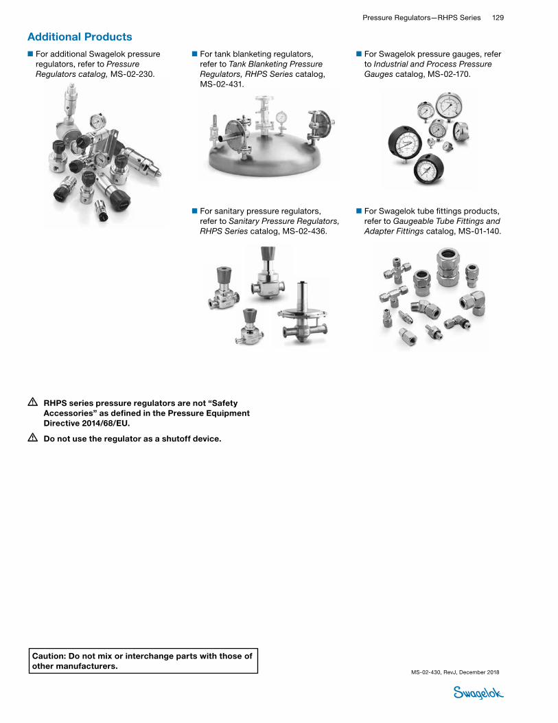
Pressure Regulators—RHPS Series 129 RHPS
REGULATORS
• RHPS series pressure regulators are not “Safety Accessories” as defined in the Pressure Equipment Directive 2014/68/EU.
• Do not use the regulator as a shutoff device.
■For Swagelok tube fittings products, refer to Gaugeable Tube Fittings and Adapter Fittings catalog, MS-01-140.
■For Swagelok pressure gauges, refer to Industrial and Process Pressure Gauges catalog, MS-02-170.
■For tank blanketing regulators, refer to Tank Blanketing Pressure Regulators, RHPS Series catalog, MS-02-431.
■For sanitary pressure regulators, refer to Sanitary Pressure Regulators, RHPS Series catalog, MS-02-436.
Additional Products■For additional Swagelok pressure
regulators, refer to Pressure Regulators catalog, MS-02-230.
Caution: Do not mix or interchange parts with those of other manufacturers.
MS-02-430, RevJ, December 2018

IntroductionSince 1947, Swagelok has designed, developed, and manufactured high-quality, general-purpose and specialty fluid system products to meet the evolving needs of global industries. Our focus is on understanding our customers’ needs, finding timely solutions, and adding value with our products and services.
We are pleased to provide this global edition of the book-bound Swagelok Product Catalog, which compiles more than 100 separate product catalogs, technical bulletins, and reference documents into one convenient, easy-to-use volume. Each product catalog is up to date at the time of printing, with its revision number shown on the last page the individual catalog; for example, the Swagelok Gaugeable Tube Fittings and Tube Adapters catalog is MS-01-140, RevW. Subsequent revisions will supersede the printed version and will be posted on the Swagelok website and in the Swagelok elec-tronic Desktop Technical Reference (eDTR) tool.
For more information, visit your Swagelok website or contact your authorized Swagelok sales and service representative.
Safe Product SelectionWhen selecting a product, the total system design must be considered to ensure safe, trouble-free performance. Function, material compatibility, adequate ratings, proper installation, operation, and maintenance are the responsibilities of the system designer and user.
Warranty InformationSwagelok products are backed by The Swagelok Limited Lifetime Warranty. For a copy, visit swagelok.com or contact your authorized Swagelok representative.
Swagelok, Ferrule-Pak, Goop, Hinging-Collecting, IGC, Kenmac, Micro-Fit, Nupro, Snoop, Sno-Trik, SWAK, VCO, VCR, Ultra-Torr, Whitey—TM Swagelok Company15-7 PH—TM AK Steel Corp.AccuTrak, Beacon, Westlock—TM Tyco International ServicesAflas—TM Asahi Glass Co., Ltd.ASCO, El-O-Matic—TM EmersonAutoCAD—TM Autodesk, Inc.CSA—TM Canadian Standards AssociationCrastin, DuPont, Kalrez, Krytox, Teflon, Viton—TM E.I. duPont Nemours and CompanyDeviceNet—TM ODVADyneon, Elgiloy, TFM—TM Dyneon Elgiloy—TM Elgiloy Specialty Metals FM—TM FM GlobalGrafoil—TM GrafTech International Holdings, Inc.Honeywell, MICRO SWITCH—TM HoneywellMAC—TM MAC ValvesMicrosoft, Windows—TM Microsoft Corp.NACE—TM NACE InternationalPH 15-7 Mo, 17-7 PH—TM AK Steel Corppicofast—Hans Turck KGPillar—TM Nippon Pillar Packing Company, Ltd.Raychem—TM Tyco Electronics Corp.Sandvik, SAF 2507—TM Sandvik ABSimriz—TM Freudenberg-NOKSolidWorks—TM SolidWorks CorporationUL—Underwriters Laboratories Inc.Xylan—TM Whitford Corporation© 2018 Swagelok Company
Caution: Do not mix or interchange parts with those of other manufacturers.