line pressure regulators - fiorentini · line pressure regulators *as approved by local codes and...
TRANSCRIPT
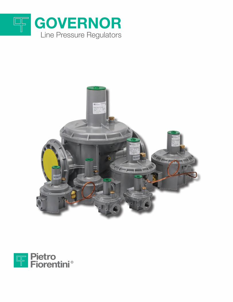
governorLine Pressure Regulators

The GOVERNOR family of regulators are ideal for a wide range of residential through large industrial applications. The materials and soft parts used in the construction of the GOVERNOR regulators make them suitable for use with natural gas, LPG, Propane air and other non-corrosive gases.
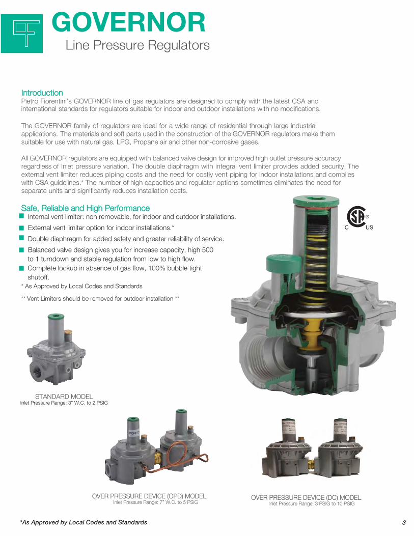
Safe, Reliable and High Performance Internal vent limiter: non removable, for indoor and outdoor installations.
External vent limiter option for indoor installations.*
Double diaphragm for added safety and greater reliability of service.
* As Approved by Local Codes and Standards
OVER PRESSURE DEVICE (OPD) MODELInlet Pressure Range: 7” W.C. to 5 PSIG
IntroductionPietro Fiorentini’s GOVERNOR line of gas regulators are designed to comply with the latest CSA and international standards for regulators suitable for indoor and outdoor installations with no modifications.
All GOVERNOR regulators are equipped with balanced valve design for improved high outlet pressure accuracy regardless of Inlet pressure variation. The double diaphragm with integral vent limiter provides added security. The external vent limiter reduces piping costs and the need for costly vent piping for indoor installations and complies with CSA guidelines.* The number of high capacities and regulator options sometimes eliminates the need for separate units and significantly reduces installation costs.
Balanced valve design gives you for increase capacity, high 500 to 1 turndown and stable regulation from low to high flow. Complete lockup in absence of gas flow, 100% bubble tight shutoff.
STANDARD MODELInlet Pressure Range: 3” W.C. to 2 PSIG
GOVERNORLine Pressure Regulators
*As Approved by Local Codes and Standards
■
■
■
■
■
OVER PRESSURE DEVICE (DC) MODEL
** Vent Limiters should be removed for outdoor installation **
3
Inlet Pressure Range: 3 PSIG to 10 PSIG
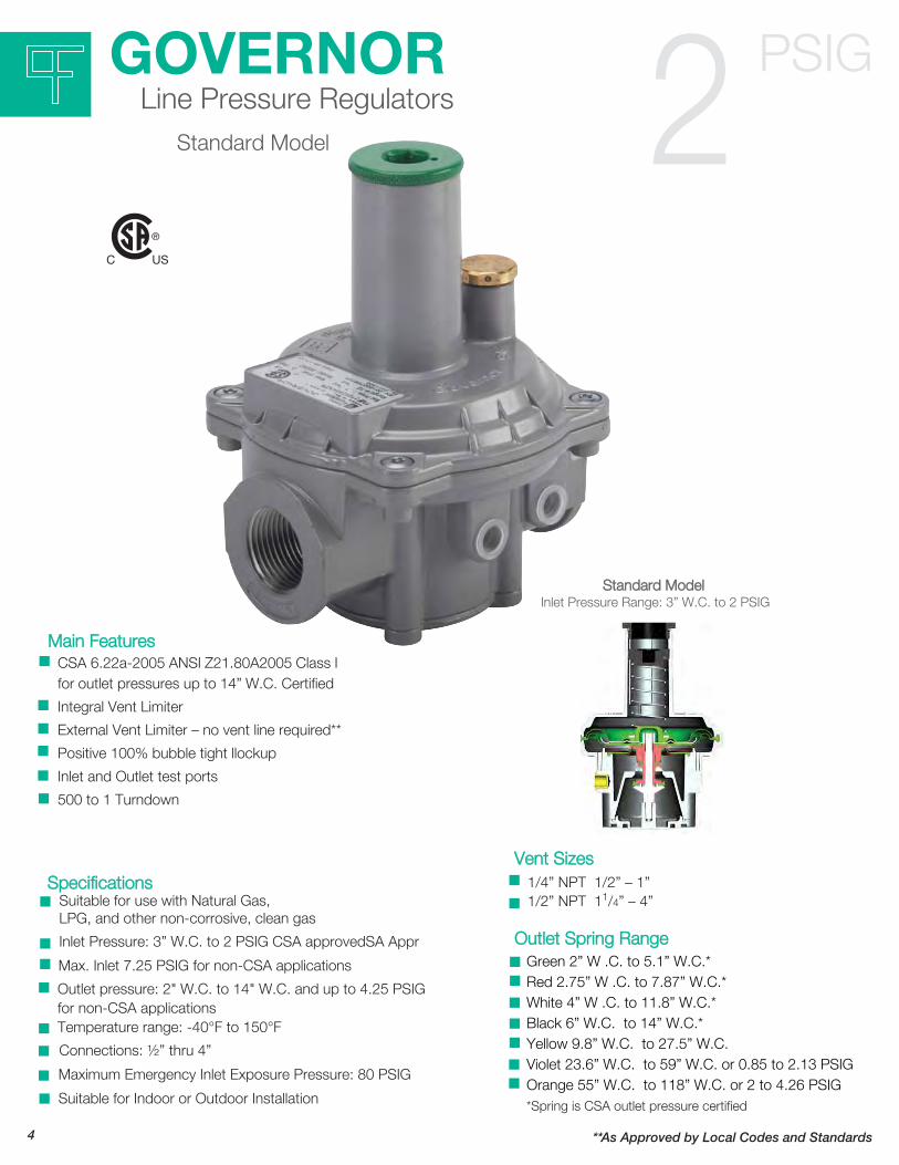
Main FeaturesCSA 6.22a-2005 ANSI Z21.80A2005 Class I for outlet pressures up to 14” W.C. Certified
Integral Vent Limiter
External Vent Limiter – no vent line required**
Positive 100% bubble tight l ockup
Inlet and Outlet test ports
500 to 1 Turndown
Suitable for use with Natural Gas, LPG, and other non-corrosive, clean gas
Inlet Pressure: 3” W.C. to 2 PSIG CSA approved
Max. Inlet 7.25 PSIG for non-CSA applications
Outlet pressure: 2" W.C. to 14" W.C. and up to 4.25 PSIG for non-CSA applicationsTemperature range: -40°F to 150°F
Connections: ½” thru 4”
Maximum Emergency Inlet Exposure Pressure: 80 PSIG
Suitable for Indoor or Outdoor Installation
Specifications
Outlet Spring Range
*Spring is CSA outlet pressure certified
Standard Model Inlet Pressure Range: 3” W.C. to 2 PSIG
GOVERNORLine Pressure Regulators
Standard Model
PSIG2
1/4” NPT 1/2” – 1” 1/2” NPT 11/4” – 4”
Vent Sizes
Green 2” W .C. to 5.1” W.C.*Red 2.75” W .C. to 7.87” W.C.*White 4” W .C. to 11.8” W.C.*Black 6” W.C. to 14” W.C.*Yellow 9.8” W.C. to 27.5” W.C.Violet 23.6” W.C. to 59” W.C. or 0.85 to 2.13 PSIG Orange 55” W.C. to 118” W.C. or 2 to 4.26 PSIG
■
■
■
■
■
■
■
■
■
■
■
■
■
■
■
■
■
■
■
■
■
■
■
4 **As Approved by Local Codes and Standards
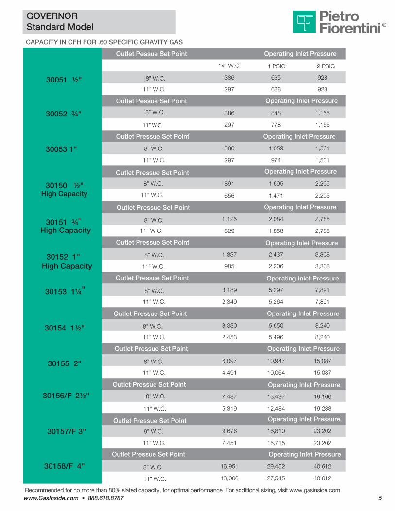
Recommended for no more than 80% slated capacity, for optimal performance. For additional sizing, visit www.gasinside.comwww.GasInside.com • 888.618.8787 5
GOVERNORStandard Model
CAPACITY IN CFH FOR .60 SPECIFIC GRAVITY GAS
Outlet Pessue Set Point
14” W.C.
Operating Inlet Pressure
1 PSIG 2 PSIG
386 635 928
297 628 92811” W.C.
Outlet Pessue Set Point
386 848 1,155
11” W.C. 297 778 1,155
Outlet Pressue Set Point Operating Inlet Pressure
386 1,059 1,501
11” W.C. 297 974 1,501
891 1,695 2,205
High Capacity 11” W.C. 656 1,471 2,205
1,125 2,084 2,785
High Capacity 11” W.C. 829 1,858 2,785
1,337 2,437 3,308
985 2,206 3,308
3,189 5,297 7,891
11” W.C. 2,349 5,264 7,891
3,330 5,650 8,240
11” W.C. 2,453 5,496 8,240
6,097 10,947 15,087
11” W.C. 4,491 10,064 15,087
Operating Inlet Pressure
Operating Inlet Pressure
Operating Inlet Pressure
Operating Inlet Pressure
Operating Inlet Pressure
Operating Inlet Pressure
Operating Inlet Pressure
Outlet Pressue Set Point
Outlet Pressue Set Point
Outlet Pressue Set Point
Outlet Pressue Set Point
Outlet Pressue Set Point
Outlet Pressue Set Point
Outlet Pressue Set Point
High Capacity 11” W.C.
30051 ½" 8” W.C.
30052 ¾" 8” W.C.
30053 1" 8” W.C.
30150 ½" 8” W.C.
30151 ¾" 8” W.C.
30152 1" 8” W.C.
30153 1¼" 8” W.C.
30154 1½" 8” W.C.
30155 2" 8” W.C.
9,676 16,810 23,202
7,451 15,715 23,202
16,951 29,452 40,612
13,066 27,545 40,612
Operating Inlet Pressure
Operating Inlet Pressure
11” W.C.
Outlet Pressue Set Point
8” W.C.
11” W.C.
Outlet Pressue Set Point
Operating Inlet Pressure
30156/F 2½" 8” W.C. 7,487 13,497 19,166
5,319 12,484 19,238
11” W.C.
30158/F 4" 8” W.C.
30157/F 3"

Main Features
CSA 6.22a-2005 ANSI Z21.80A2005 Class I andClass II for outlet pressures up to 14” W.C. and inletpressures up to 5 PSIG CertifiedIntegral Vent Limiter
External Vent Limiter – no vent line required**
Positive 100% bubble tight lockup
Inlet and Outlet test ports
500 to 1 Turndown
Suitable for use with Natural Gas, LPG, and other non-corrosive, clean gas
Inlet Pressure: 7” W.C. to 5 PSIG CSA approved
Max. Inlet 7.25 PSIG for non-CSA applications
Outlet pressure: 2" W.C. to 1" W.C. and up to 4.25 PSIG for non-CSA applicationsTemperature range: -40°F to 150°F
Connections: ½” thru 4”
Maximum Emergency Inlet Exposure Pressure: 80 PSIG
Suitable for Indoor or Outdoor Installation
Specifications
Outlet Spring Range
*Spring is CSA outlet pressure certified
Over Pressure Device (OPD) Model Inlet Pressure Range: 7” W.C. to 5 PSIG
GOVERNORLine Pressure Regulators
Over Pressure Device (OPD) Model
PSIG5
1/4” NPT 1/2” – 1” 1/2” NPT 11/4” – 4”
Vent Sizes
Green 2” W .C. to 5.1” W.C.*Red 2.75” W .C. to 7.87” W.C.*White 4” W .C. to 11.8” W.C.*Black 6” W.C. to 14” W.C.*Yellow 9.8” W.C. to 27.5” W.C.*Violet 23.6” W.C. to 59” W.C. or 0.85 to 2.13 PSIG *Orange 55” W.C. to 118” W.C. or 2 to 4.26 PSIG
■
■
■
■
■
■
■
■
■
■
■
■
■
■
■
■
■
■
■
■
■
■
■
Worker & Monitor for added Safety■
6 **As Approved by Local Codes and Standards
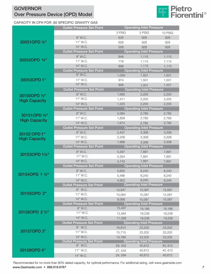
Recommended for no more than 80% slated capacity, for optimal performance. For additional sizing, visit www.gasinside.comwww.GasInside.com • 888.618.8787 7
Operating Inlet Pressure 3 PSIG 5 PSIG 10 PSIG
8” W.C. 635 928 928
628 928 928
558 928
8” W.C. 848 1,115 1,115
778 1,115 1,115
698 1,115
1,059 1,501 1,501
974 1,501 1,501
8” W.C.
11” W.C.14” W.C. 906 1,501
8” W.C. 1,695 2,205 2,20511” W.C. 1,471 2,205 2,205
1,325 2,205
8” W.C. 2,084 2,785 2,785
11” W.C. 1,858 2,785 2,785
14” W.C. 1,674 2,785
8” W.C. 2,437 3,308 3,308
11” W.C. 2,206 3,308 3,308
1,988 3,308
8” W.C. 5,297 7,891 7,89111” W.C. 5,264 7,891 7,891
4,743 7,891
8” W.C. 5,650 8,240 8,24011” W.C. 5,496 8,240 8,240
4,952 8,240
10,947 15,087 15,087
10,064 15,087 15,087
8” W.C.
11” W.C.
14” W.C. 9,068 15,087 15,087
16,810 23,202 23,202
15,715 23,202 23,202
8” W.C.
11” W.C. 14” W.C. 13,768 23,202 23,202
29, 452 40,612 40, 612
40,612 40, 61227, 545 24, 094 40,612 40,612
Outlet Pressure Set Point Operating Inlet Pressure
8” W.C.11” W.C.
14” W.C.
Outlet Pressure Set Point Operating Inlet Pressure
14” W.C.
Outlet Pressure Set Point Operating Inlet Pressure
14” W.C.
Outlet Pressure Set Point Operating Inlet Pressure
14” W.C.Outlet Pressure Set Point Operating Inlet Pressure
Outlet Pressure Set Point Operating Inlet Pressure
14” W.C.
Outlet Pressure Set Point Operating Inlet Pressure
Outlet Pressure Set Point1,501
Operating Inlet Pressure
14” W.C.
Outlet Pressure Set Point1,115
Operating Inlet Pressure
14” W.C.
Outlet Pressure Set Point928
Operating Inlet Pressure
Outlet Pressure Set Point
2,205
2,785
3,308
7,891
8,240
11” W.C.
11” W.C.
8” W.C.
11” W.C.
14” W.C.
13,497 19,186 19,166
12,484 19,238 19,238
11,358 19,238 19,238
Outlet Pressure Set Point Operating Inlet Pressure
GOVERNOROver Pressure Device (OPD) Model
CAPACITY IN CFH FOR .60 SPECIFIC GRAVITY GAS
30051OPD ½"
30052OPD ¾"
30053OPD 1"
30150OPD ½" High Capacity
30153OPD 1¼"
30154OPD 1 ½"
30155OPD 2"
30157OPD 3”
30158OPD 4"
30151OPD ¾" High Capacity
30152 OPD 1" High Capacity
30156OPD 2 ½"
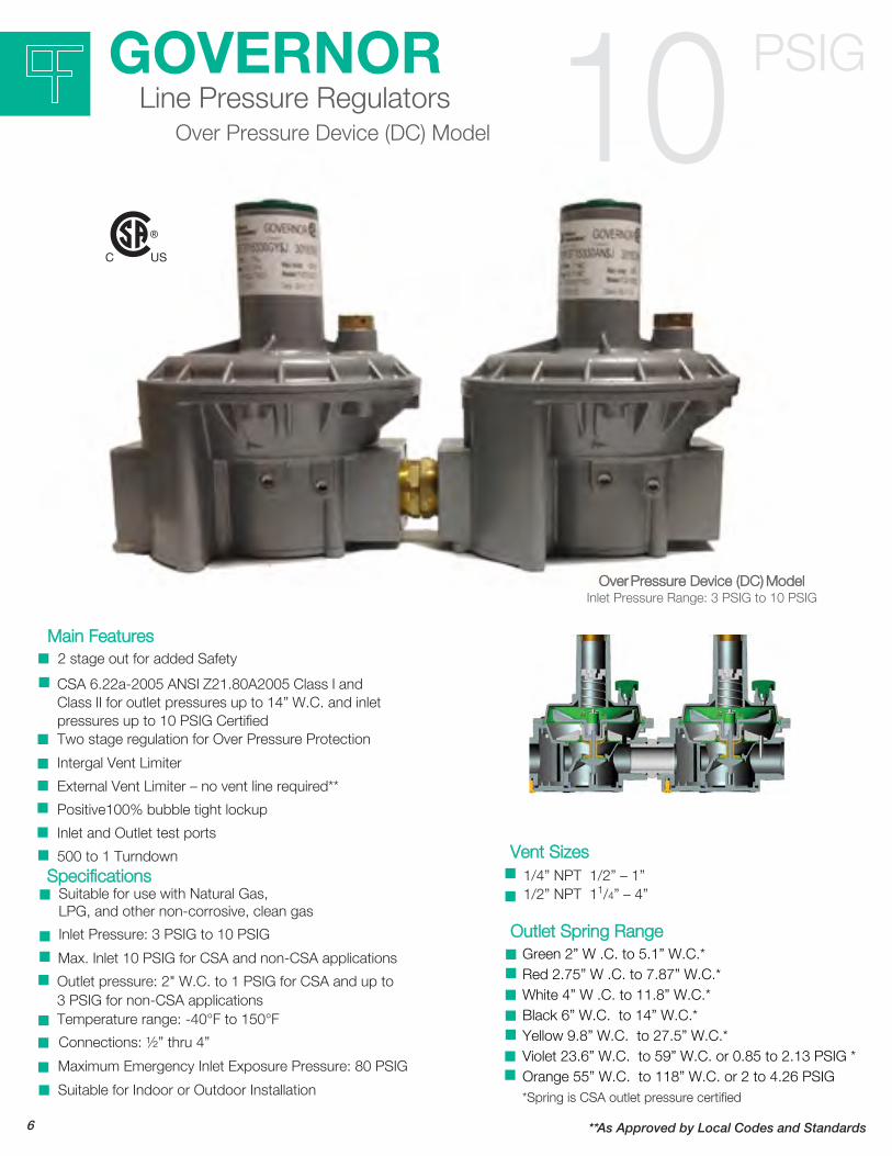
Main Features
CSA 6.22a-2005 ANSI Z21.80A2005 Class I andClass II for outlet pressures up to 14” W.C. and inletpressures up to 10 PSIG CertifiedTwo stage regulation for Over Pressure Protection
Intergal Vent Limiter
External Vent Limiter – no vent line required**
Positive100% bubble tight lockup
Inlet and Outlet test ports
500 to 1 Turndown
Suitable for use with Natural Gas,LPG, and other non-corrosive, clean gas
Inlet Pressure: 3 PSIG to 10 PSIG
Max. Inlet 10 PSIG for CSA and non-CSA applications
Outlet pressure: 2" W.C. to 1 PSIG for CSA and up to3 PSIG for non-CSA applicationsTemperature range: -40°F to 150°F
Connections: ½” thru 4”
Maximum Emergency Inlet Exposure Pressure: 80 PSIG
Suitable for Indoor or Outdoor Installation
Specifications
Outlet Spring Range
*Spring is CSA outlet pressure certified
Over Pressure Device (DC) Model Inlet Pressure Range: 3 PSIG to 10 PSIG
GOVERNORLine Pressure Regulators
Over Pressure Device (DC) Model
PSIG10
1/4” NPT 1/2” – 1” 1/2” NPT 11/4” – 4”
Vent Sizes
Green 2” W .C. to 5.1” W.C.*Red 2.75” W .C. to 7.87” W.C.*White 4” W .C. to 11.8” W.C.*Black 6” W.C. to 14” W.C.*Yellow 9.8” W.C. to 27.5” W.C.*Violet 23.6” W.C. to 59” W.C. or 0.85 to 2.13 PSIG *Orange 55” W.C. to 118” W.C. or 2 to 4.26 PSIG
■
■
■
■
■
■
■
■
■
■
■
■
■
■
■
■
■
■
■
■
■
■
■
2 stage out for added Safety■
6 **As Approved by Local Codes and Standards
■
Recommended for no more than 80% slated capacity, for optimal performance. For additional sizing, visit www.gasinside.comwww.GasInside.com • 888.618.8787 9
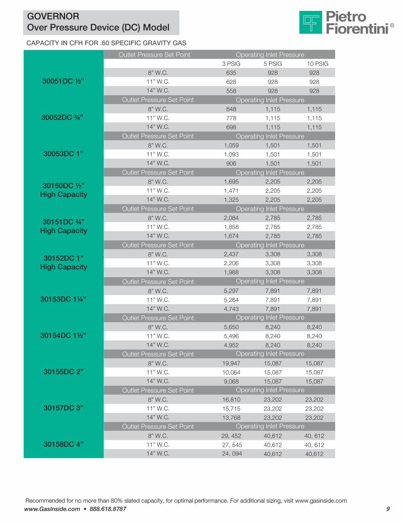
GOVERNOROver Pressure Device (DC) Model
CAPACITY IN CFH FOR .60 SPECIFIC GRAVITY GAS
Outlet Pressure Set Point Operating Inlet Pressure3 PSIG 5 PSIG 10 PSIG
635 928 928
628 928 928
558 928 928
Operating Inlet Pressure848 1,115 1,115
778 1,115 1,115
698 1,115 1,115
Operating Inlet Pressure1,059 1,501 1,501
1,093 1,501 1,501
906 1,501 1,501
Operating Inlet Pressure1,695 2,205 2,205
1,471 2,205 2,205
1,325 2,205 2,205
Operating Inlet Pressure2,084 2,785 2,785
1,858 2,785 2,785
1,674 2,785 2,785
Operating Inlet Pressure2,437 3,308 3,308
2,206 3,308 3,308
8” W.C.
11” W.C.
14” W.C.
Outlet Pressure Set Point 8” W.C.
11” W.C.
14” W.C.
Outlet Pressure Set Point 8” W.C.
11” W.C.
14” W.C.
Outlet Pressure Set Point 8” W.C.
11” W.C.
14” W.C.
Outlet Pressure Set Point 8” W.C.
11” W.C.
14” W.C.
Outlet Pressure Set Point 8” W.C.
11” W.C.
14” W.C. 1,988 3,308 3,308
Operating Inlet Pressure5,297 7,891 7,891
5,264 7,891 7,891
4,743 7,891 7,891Operating Inlet Pressure
5,650 8,240 8,240
5,496 8,240 8,240
4,952 8,240 8,240Operating Inlet Pressure
19,947 15,087 15,087
10,064 15,087 15,087
9,068 15,087 15,087Operating Inlet Pressure
16,810 23,202 23,202
15,715 23,202 23,202
13,768 23,202 23,202Operating Inlet Pressure
29, 452 40,612 40, 612
40,612 40, 612
Outlet Pressure Set Point 8” W.C.
11” W.C.
14” W.C.
Outlet Pressure Set Point 8” W.C.
11” W.C.
14” W.C.
Outlet Pressure Set Point 8” W.C.
11” W.C.
14” W.C.
Outlet Pressure Set Point 8” W.C.
11” W.C.
14” W.C.
Outlet Pressure Set Point 8” W.C.
11” W.C.
14” W.C.27, 545 24, 094 40,612 40,612
30051DC ½”
30052DC ¾”
30053DC 1”
30150DC ½” High Capacity
30151DC ¾” High Capacity
30152DC 1” High Capacity
30153DC 1¼”
30154DC 1½”
30155DC 2”
30157DC 3”
30158DC 4”

Recommended for no more than 80% slated capacity, for optimal performance. For additional sizing, visit www.gasinside.com
GOVERNORStandard Model - Dimensions
DIMENSIONS (IN INCHES)
Model # Size A B C D E FWeight(Lbs)
30051 1/2” NPT 4.124.12 4.45 w/Filter
- 1/2 - 5.59 - 1.54
30052 3/4” NPT 4 4.29 w/Filter - 3/4 - 5.59 - 1.54
30053 1” NPT 4 4.29 w/Filter - 1 - 5.59 - 1.54
30150 1/2” NPT 5.43 1/2 - 6.89 - 2.75
30151 3/4” NPT 5.28
-
- 3/4 - 6.89 - 2.75
30152 1” NPT 5.28 - 1 - 6.89 - 2.75
7.64 - 10 - 7.530153 1 1/4” NPT
30154 1 1/2” NPT 7.64
1 1/4
1 1/2 - 10 - 7.5
30155 9.29 - 2 - 12.44 13.74 12.34
- - 17.09 27.5630157/F
30158/F -
3 ANSI 150
4 ANSI 150 - 19.76 27.56
-
-
16.9
16.9
2” NPT
2 1/2” FLANGED
3” FLANGED
4” FLANGED
30156/F - - 17.09 27.563 ANSI 150 16.9
DIMENSIONS (IN INCHES)
Model # Size A B C D E FWeight (Lbs)
30051 1/2” NPT 8.86 - 1/2 - 5.59 - 3.2530052 3/4” NPT 8.86 - 3/4 - 5.59 - 3.2530053 1” NPT 8.86 - 1 - 5.59 - 3.2530150 1/2” NPT 11.22 - 1/2 - 6.89 - 5.7530151 3/4” NPT 11.22 - 3/4 - 6.89 - 5.7530152 1” NPT 11.22 - 1 - 6.89 - 5.7530153 1 1/4” NPT 16.61 - 1 1/4 - 10 - 15.530154 1 1/2” NPT 16.61 - 1 1/2 - 10 - 15.530155 19.88 - 2 - 12.44 13.74 25
30157/F- 33.93 3 ANSI 150 - 17.09 56
30158/F
2” NPT
2 1/2” FLANGED3” FLANGED4” FLANGED - 33.93 4 ANSI 150 - 19.76 56
30156/F
- 33.93 3 ANSI 150 - 17.09 56
GOVERNOR Over Pressure Device (OPD) Model & Dual Cut (DC) Model - Dimensions
10

www.GasInside.com • 888.618.8787 11
Warranty Policy
The Seller undertakes to remedy any defects, lack of quality or non‐conformity of the goods contract for which he is responsible, provided such defects have been notified in accordance within 10 (ten) days from the occurrence. The Seller may either repair or replace the goods which have shown to be defective.
In case of repair, request to return product(s) for repair must be pre-approved in writing by our Sales Department. The product(s) shall be returned pre-paid to Pietro Fiorentini USA.Seller is not responsible for defects due to: natural wearing, Buyer’s inexperience, negligence, tampering or wrong assemblage, overcome of limits conditions, non authorized intervention, force majeure or fault of the Buyer. The duration of the guarantee is twenty four months from delivery of goods.
The present warranty is not enforceable in case of lack of payment in the agreed terms. It is agreed that the obligation to repair or replace the defective goods is in lieu of any other legal guarantee or liability of the Seller, whether contractual or non‐contractual, which may arise out of or in relation with the goods supplied (e.g. compensation of damages, loss of profit, recall campaigns, etc.). For goods that have been purchased from sub-suppliers, the warranty guarantee granted by them is herewith extended to the Buyer.
Materials ■ Body & Cover: Aluminum Alloy■ External Coatings: Polyurethane
paint on request■ Diaphragm, O Rings & Valve:
Nitrile Rubber■ Diaphragm Pan: Aluminized Steel
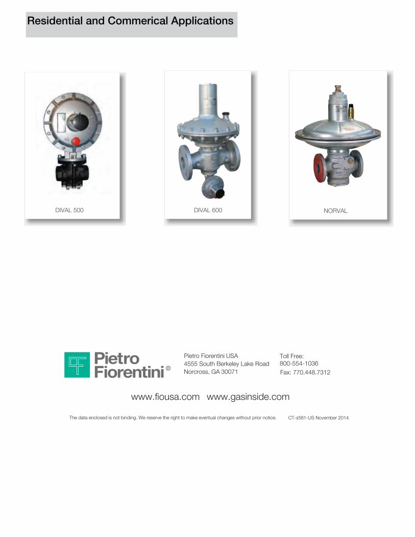
CT-s581-US November 2014
Pietro Fiorentini USA 4555 South Berkeley Lake Road Norcross, GA 30071 Fax: 770.448.7312
Toll Free:800-554-1036
DIVAL 600DIVAL 500 NORVAL
www.fiousa.com www.gasinside.com
The data enclosed is not binding. We reserve the right to make eventual changes without prior notice.
Residential and Commerical Applications