presentazione di powerpoint - · pdf filelds obu location determination system on board unit...
TRANSCRIPT
RH INOS“Railway High Integrity Navigation Overlay System”
Prof. Alessandro NERI
Il contributo dei Servizi Satellitari ai Trasporti e alla Navigazione
12 aprile 2016
Ministero delle Infrastrutture e Trasporti
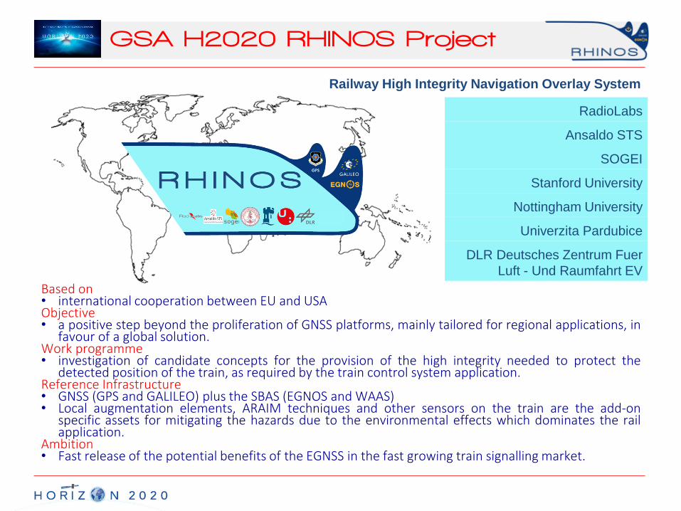
GSA H2020 RHINOS Project
Based on• international cooperation between EU and USAObjective• a positive step beyond the proliferation of GNSS platforms, mainly tailored for regional applications, in
favour of a global solution.Work programme• investigation of candidate concepts for the provision of the high integrity needed to protect the
detected position of the train, as required by the train control system application.Reference Infrastructure• GNSS (GPS and GALILEO) plus the SBAS (EGNOS and WAAS)• Local augmentation elements, ARAIM techniques and other sensors on the train are the add-on
specific assets for mitigating the hazards due to the environmental effects which dominates the railapplication.
Ambition• Fast release of the potential benefits of the EGNSS in the fast growing train signalling market.
Railway High Integrity Navigation Overlay System
RadioLabs
Ansaldo STS
SOGEI
Stanford University
Nottingham University
Univerzita Pardubice
DLR Deutsches Zentrum Fuer
Luft - Und Raumfahrt EV

Project Objectives
• Objective 1: To DEFINE THE ARCHITECTURE of a train Location Detection System (LDS) and of the supporting infrastructure, with the following properties
• joint use of GPS and GALILEO and wide area integration monitoring and augmentation networks (WAAS, EGNOS)
• standard interface for providing Safety of Life services for railways through SBASs, regional augmentations or hybrid SBAS/GBAS systems;
• compliance with European and US railway requirements and regulations;
• sharing as much as possible of the supporting infrastructure and on board processing, including new developments such as ARAIM, with the avionics (and automotive) field,
• provisioning of a set of functionalities tailored to the specific needs of the rail sector.
Project Objectives
• Objective 2: To assess the performance of the defined architecture by means of:
• a PROOF-OF-CONCEPT integrating, in a virtualized testbed,
• real railway environment data sets,
• rare GPS SIS faults
• simulated faults for the new constellations;
• ANALYTICAL METHODS for verification and safety evidence of defined architecture according to railway safety standards (e.g. CENELEC EN 50129, etc.)
Project Objectives
• Objective 3: To contribute to the missing standard in the railway sector about the way of integration of GNSS-based LDS, into current Train Control System standards (e.g. ERTMS)
• by publishing a comprehensive GUIDE on how to employ, in a cost-
effective manner, GNSS, SBAS and other local infrastructures in safety related rail applications worldwide,
• by defining a STRATEGIC ROADMAP for the adoption of an international standard based on the same guide.

Roadmap
1. Revision of requirements and functionalities expected worldwide in the short, medium and long term, with specific emphasis to the European and US markets.
2. Harmonization between requirements and functionalities for avionics and railways applications.
3. Investigation of candidate solutions (augmentation and integrity monitoring infrastructures, and On Board Units)
• evaluation of performance,
• cost and benefits,
• SWOT (Strength, Weakness, Opportunities, and Threats)
4. Cost and Benefits trade-off and selection of the reference architecture among the candidate solutions.
5. Realization of a Proof of Concept
6. Verification of the reference architecture performance
• appropriate analytical methods and tools
7. Dissemination and consensus sharing.
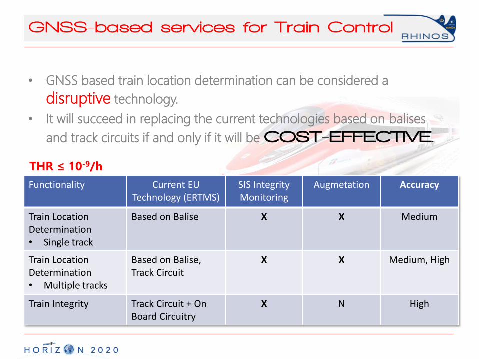
GNSS-based services for Train Control
Functionality Current EU Technology (ERTMS)
SIS IntegrityMonitoring
Augmetation Accuracy
Train Location Determination• Single track
Based on Balise X X Medium
Train Location Determination• Multiple tracks
Based on Balise,Track Circuit
X X Medium, High
Train Integrity Track Circuit + On Board Circuitry
X N High
• GNSS based train location determination can be considered a
disruptive technology.
• It will succeed in replacing the current technologies based on balises
and track circuits if and only if it will be COST-EFFECTIVE.
THR ≤ 10-9/h
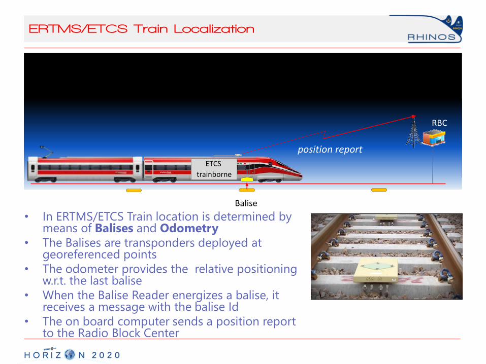
ERTMS/ETCS Train Localization
GPS
RBC
Balise
position report
ETCS
trainborne
• In ERTMS/ETCS Train location is determined by means of Balises and Odometry
• The Balises are transponders deployed at georeferenced points
• The odometer provides the relative positioning w.r.t. the last balise
• When the Balise Reader energizes a balise, it receives a message with the balise Id
• The on board computer sends a position report to the Radio Block Center
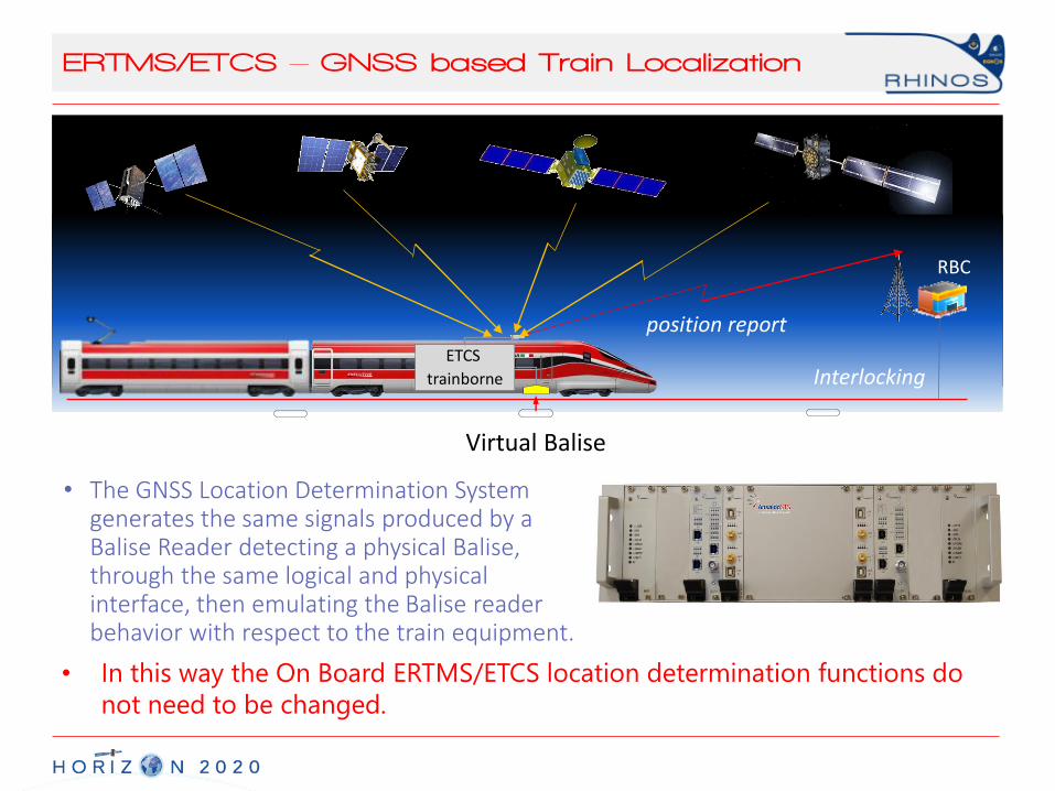
ERTMS/ETCS – GNSS based Train Localization
• The GNSS Location Determination System generates the same signals produced by a Balise Reader detecting a physical Balise, through the same logical and physical interface, then emulating the Balise reader behavior with respect to the train equipment.
GPS BEIDOU
RBC
Virtual Balise
position report
ETCS
trainborne Interlocking
• In this way the On Board ERTMS/ETCS location determination functions do
not need to be changed.
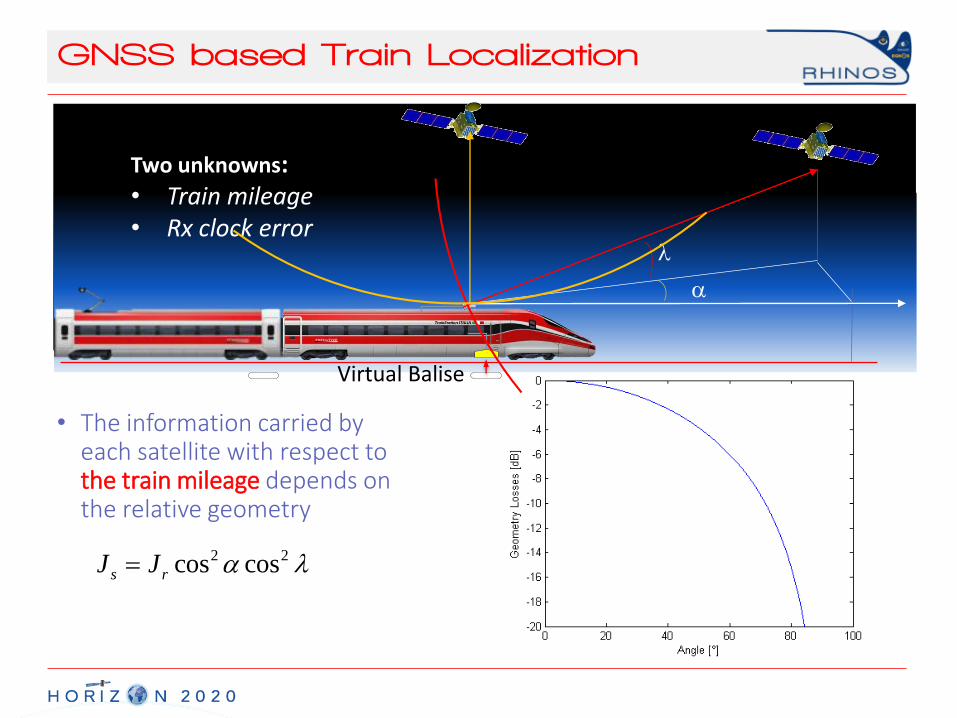
GNSS based Train Localization
GPS BEIDOU
Virtual Balise
a
l
• The information carried by each satellite with respect to the train mileage depends on the relative geometry
2 2cos coss rJ J a l
Two unknowns:• Train mileage• Rx clock error

Multiple Tracks
GPS BEIDOU
b
l
• The information carried by eachsatellite with respect to multiple track discrimination depends on the relative geometry
2 2cos coss rJ J b l

Overlay Architecture
• Selection of candidate solutions concerning both augmentation and integrity monitoring infrastructures, and On Board Units starts from the mitigation actions related to the hazards identified during the Hazard Analysis
Hazards Mitigations
Clock runoffs SBAS & LADGNSS
Ephemeris Faults SBAS & LADGNSS
Ionospheric storms LADGNSS (multifrequency)
Signal Distortions SBAS & LADGNSS
Constellation Rotations SBAS & LADGNSS
Multipath Train Autonomous Integrity Monitoring
Jamming, Spoofing DBF + High Resilience DSPTrain Autonomous Integrity Monitoring
Hazard Analysis
Mitigation Actions
Candidate Solutions
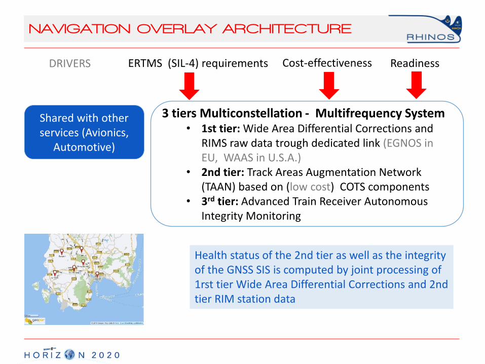
NAVIGATION OVERLAY ARCHITECTURE
DRIVERS ERTMS (SIL-4) requirements Cost-effectiveness
3 tiers Multiconstellation - Multifrequency System• 1st tier: Wide Area Differential Corrections and
RIMS raw data trough dedicated link (EGNOS in EU, WAAS in U.S.A.)
• 2nd tier: Track Areas Augmentation Network (TAAN) based on (low cost) COTS components
• 3rd tier: Advanced Train Receiver Autonomous Integrity Monitoring
Health status of the 2nd tier as well as the integrity of the GNSS SIS is computed by joint processing of 1rst tier Wide Area Differential Corrections and 2nd tier RIM station data
Readiness
Shared with otherservices (Avionics,
Automotive)
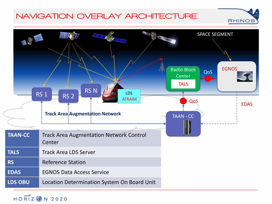
TAAN-CC Track Area Augmentation Network Control Center
TALS Track Area LDS Server
RS Reference Station
EDAS EGNOS Data Access Service
LDS OBU Location Determination System On Board Unit
NAVIGATION OVERLAY ARCHITECTURE
GPS BEIDOU
Radio Block Center
TALS
SPACE SEGMENT
QoS
EDAS
RS 1 RS 2RS N
Track Area Augmentation Network TAAN - CC
QoS
EGNOS
LDS
ATRAIM
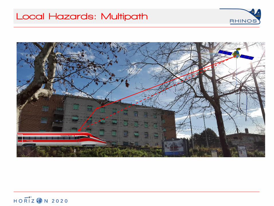
Local Hazards: Multipath
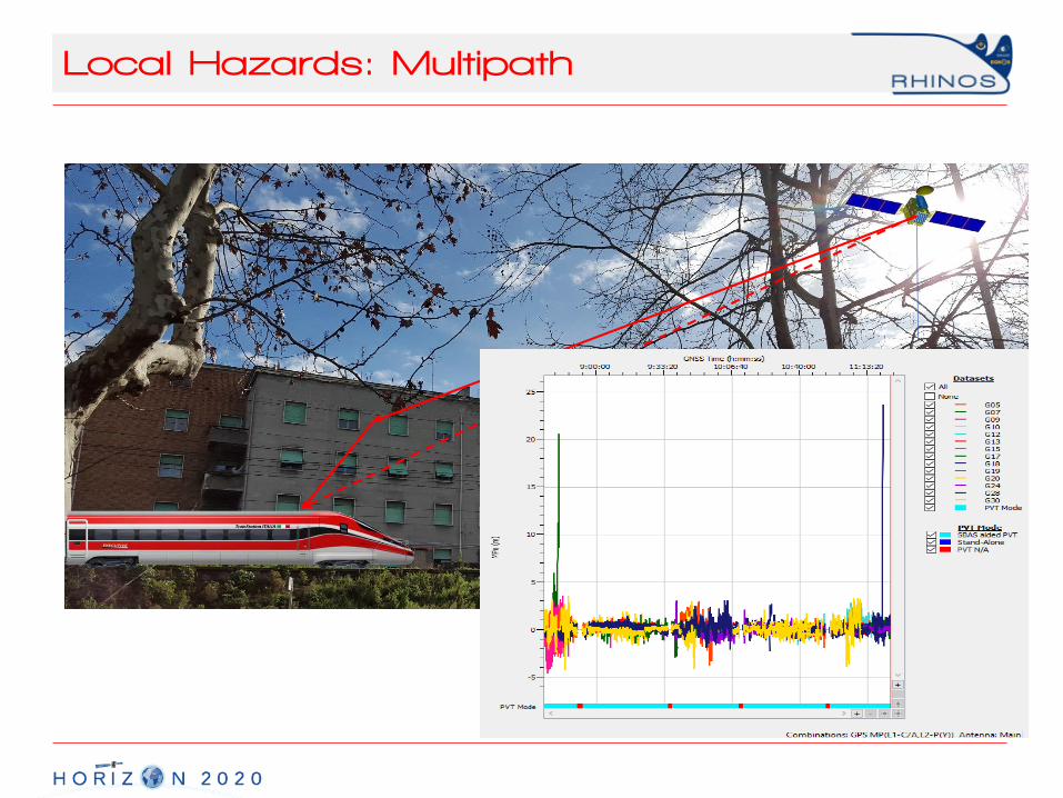
Local Hazards: Multipath

Local Hazards: Multipath

Local Hazards: Multipath
Multipath in rail environment
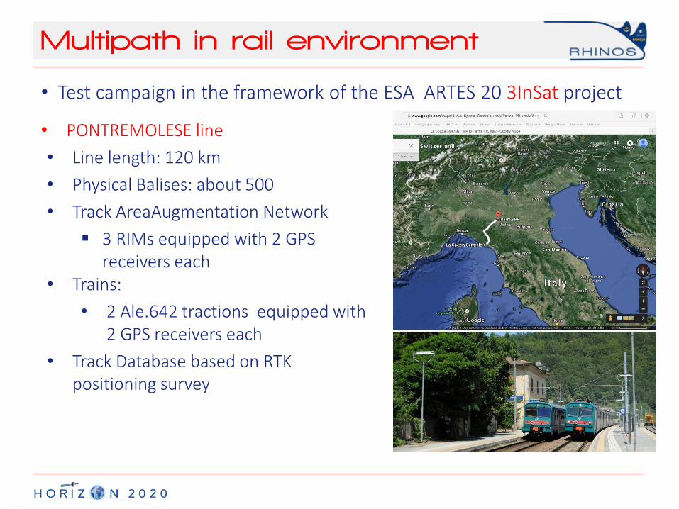
• Test campaign in the framework of the ESA ARTES 20 3InSat project
• Line length: 120 km
• Physical Balises: about 500
• Track AreaAugmentation Network
3 RIMs equipped with 2 GPS receivers each
• PONTREMOLESE line
• Trains:
• 2 Ale.642 tractions equipped with 2 GPS receivers each
• Track Database based on RTK positioning survey
Multipath in rail environment
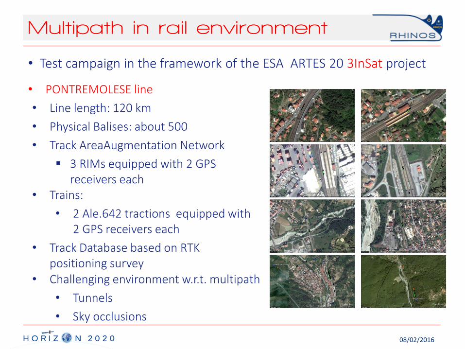
• Test campaign in the framework of the ESA ARTES 20 3InSat project
• Line length: 120 km
• Physical Balises: about 500
• Track AreaAugmentation Network
3 RIMs equipped with 2 GPS receivers each
• PONTREMOLESE line
• Trains:
• 2 Ale.642 tractions equipped with 2 GPS receivers each
• Track Database based on RTK positioning survey
• Challenging environment w.r.t. multipath
• Tunnels
• Sky occlusions
08/02/2016
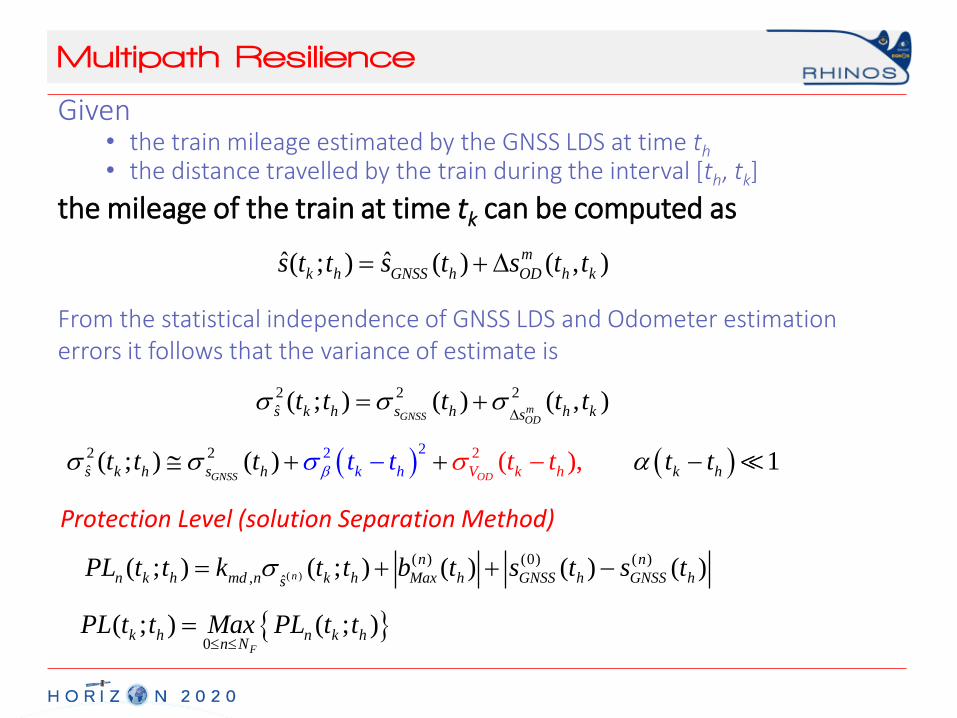
Multipath Resilience
Given • the train mileage estimated by the GNSS LDS at time th• the distance travelled by the train during the interval [th, tk]
the mileage of the train at time tk can be computed as
ˆ ˆ( ; ) ( ) ( , )m
k h GNSS h OD h ks t t s t s t t
2 2 2
ˆ ( ; ) ( ) ( , )mGNSS OD
s k h s h h kst t t t t
22 22 2
ˆ ( ),( ; ) ( ) 1GNSS ODs k h k h k hks h h Vtt t t tt tttb a
( )
( ) (0) ( )
, ˆ( ; ) ( ; ) ( ) ( ) ( )n
n n
n k h md n k h Max h GNSS h GNSS hsPL t t k t t b t s t s t
0
( ; ) ( ; )F
k h n k hn N
PL t t Max PL t t
From the statistical independence of GNSS LDS and Odometer estimation errors it follows that the variance of estimate is
Protection Level (solution Separation Method)
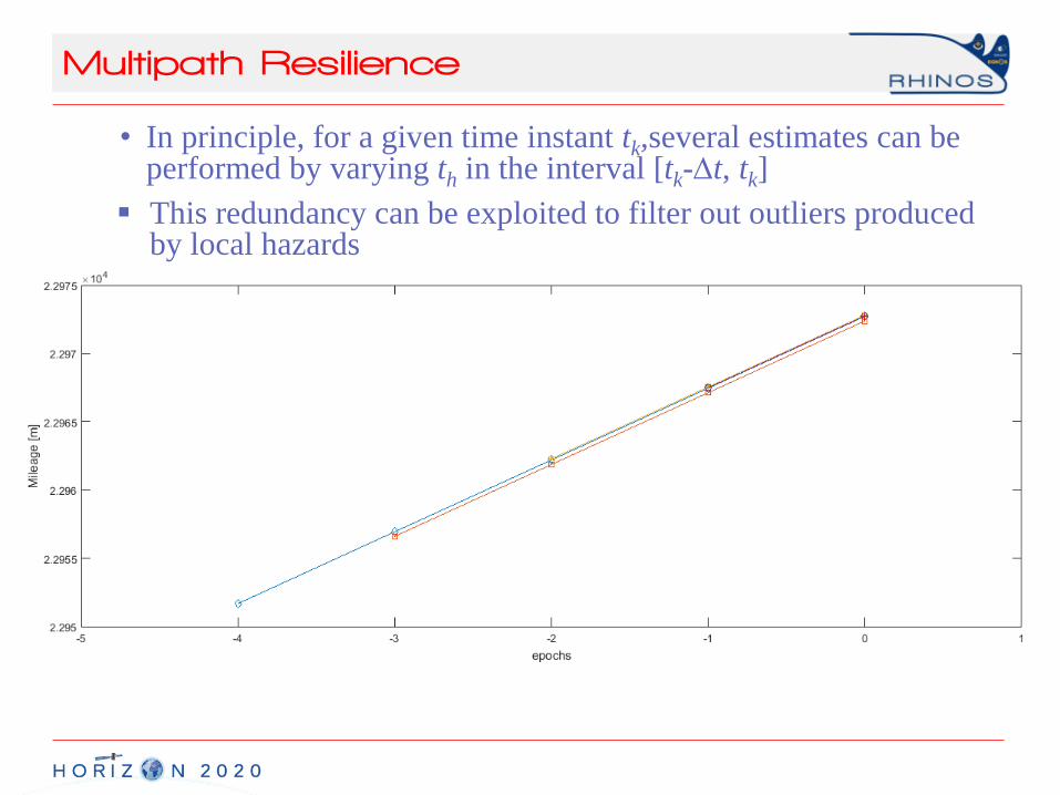
Multipath Resilience
• In principle, for a given time instant tk,several estimates can be performed by varying th in the interval [tk-t, tk]
This redundancy can be exploited to filter out outliers produced by local hazards

Multipath Resilience
Unfiltered DATA Weighted Median Filter

Advanced Integrity Monitoring
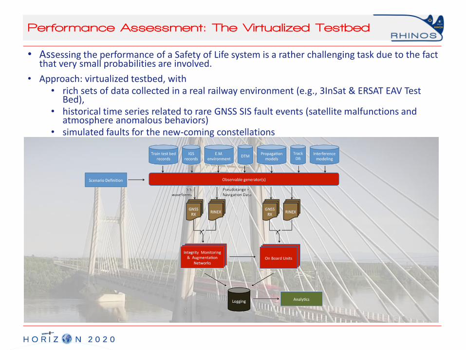
Performance Assessment: The Virtualized Testbed
• Assessing the performance of a Safety of Life system is a rather challenging task due to the fact that very small probabilities are involved.
• Approach: virtualized testbed, with • rich sets of data collected in a real railway environment (e.g., 3InSat & ERSAT EAV Test
Bed), • historical time series related to rare GNSS SIS fault events (satellite malfunctions and
atmosphere anomalous behaviors)• simulated faults for the new-coming constellations

Conclusions
• MULTI-CONSTELLATION architectures offer higher degree of flexibility to reach the SIL-4 level (recommended for high demanding accuracy in the railways applications).
• Nevertheless, the availability of an augmentation network is of paramount importance in reducing the Protection Level.
• Definition of a standard for the Railway High Integrity Navigation Overlay System is a key success factor for spreading the GNSS application into the rail.
• SHARING OF SUPPORTING INFRASTRUCTURE (i.e., augmentation) and on board processing as much as possible , including new developments such as Advanced Receiver Autonomous Integrity Monitoring (ARAIM), withAVIONICS and AUTOMOTIVE fields is a key factor for cost effectiveness.
• Definition of a strategic roadmap for the adoption of a COMMONprocedure for High Integrity Application CERTIFICATION is of primary concern.
THANKS FOR YOUR ATTENTION