prepared especially for: tps360 - gototps.com tps360 report.pdf · prepared especially for: ......
TRANSCRIPT

Prepared Especially For: TPS360Report
Sample Co.
Proposal for Project:
Processing Plant
Sample Customer Logo
Providing the Highest Value; Safely, On Time & On Budget GUARANTEED.
Page 1

Turnkey Processing Solutions, LLC 101 Shorewood Lane Shorewood, Illinois 60404
Office 815-741-3760 Fax 815-741-3766
www.turnkeyprocessing.com
Confidential
Providing the Highest Value; Safely, On Time, & on budget GUARANTEED
Proposal No. 00000-01 Proposal Date: April 1th
, 2011
Sample Plant Project
About Turnkey Processing Solutions:
TPS has a vast amount of erection and equipment installation experience. We put an extraordinary amount of
effort into ensuring that the engineering and fabrication is right before we ship the equipment to the job site.
This extra effort on the front end of the process insures that the equipment fits in the field. This dramatically
reduces the cost of equipment rental and labor costs.
Safety is of paramount importance when erecting processing plants. To insure that all mining codes, and your
company safety procedures and guidelines are followed, we work with your management personnel to develop a
safety plan before we begin the project. TPS personnel not only know what they are building, they know how to
operate and maintain the equipment as well. This reduces the stress, effort, and costs required to startup and
tune the plant.
Planning projects requires careful and diligent attention to detail. Ensuring that equipment deliveries, parts and
supplies, manpower, cranes, and all of the required resources are made available in the proper sequence is vital
to staying on track and meeting project timelines. Our project management team is very good at building these
project timelines and making sure that they are achieved.
Turnkey Processing Solutions appreciates the opportunity to provide this proposal for your application. We are
committed to provide the highest quality products and services available. It’s our goal to provide Sample Co. with
excellent service at every stage of the project.
If you have any questions concerning the scope of this proposal, we are available to meet with you in your office, over
the phone, or via email exchange. Please advise us at your earliest convenience on our proposal and how we can further
assist you.
Team TPS
Page 1

Project: Sample Plant Project Proposal No. 00000-01 Customer: Sample Customer
Confidential
Table of Contents
I. Scope:
II. Project Cost Report:
III. Lump Sum Pricing:
IV. Terms & Conditions:
V. Flows & Drawings:
Page 2

Project: Sample Plant Project Proposal No. 00000-01 Customer: Sample Customer
Confidential
I. Plant Project Plant Scope:
This section will provide you with descriptions and specifications on the equipment used in the proposed Plant and shall
include all of the Equipment and Structures required in completing this process.
Wet Plant Scope and Descriptions.
FH01, F01 & CR01-Feed Hopper, Feeder and Crusher Support.
The feed hopper, feeder and crusher system is made up of a loader charging hopper, a feeder and a crusher support structure
for the jaw crusher. The system will allow material to be fed by a front end loader into the primary crusher as described
below. Feed hopper, feeder and crusher support structure will be supplied, installed and commissioned by TPS.
Heavy-duty feed hopper includes structural steel support legs and heavy-duty V type hopper. Hopper fabricated from
3/4" mild steel plate. Hopper sidewalls to be fabricated from 3/4" mild steel plate. Hopper includes 1/2" A.R liners in
wear areas and extension wings to control spillage from the loader. Hopper shall be supported using structural steel
column members bolted to the concrete footings.
Feeder Structure shall include a heavy-duty structural steel support structure for a Lippmann 51” x 20’ Vibrating Grizzly
Feeder. Structure will include a 40 H.P. electric motor for the feeder drive and a grizzly by-pass type chute made from
1/2” thick plate and include a large access door. This will allow for the bypass of material onto undercrusher conveyor.
51" x 20' heavy-duty grizzly feeder. Twin shafted mechanism with (4) 110 MM bearings having self contained oil
lubrication. Mechanism is located below the vibrating body attached by removable assembly mount plates. Side frame
consists of 26 " wide formed side plates with bent flanges at the top & bottom. Sub-deck pan cross members 8" formed
channels on 14" spacing with (5) rows of 1/2" x 5" filler bars to form an "egg crate" design. 14' of pan, 1/2" thick hot
rolled steel plate, 11" deep. Side liners are 1/2" thick Hardox 450 AR steel plate. Bottom liners are 1/2" thick Hardox AR
450 steel plate. 5' long grizzly deck section having adjustable openings. Openings to be advised at time of order. Vertical
coil springs with spring base plates for a horizontal setting. V-belt drive parts consisting of the machine & motor sheaves
with bushing suitable for a 40 H.P. T-frame motor, v-belts, independently mounted pivoted-type motor base, and belt
guard.
Heavy-duty crusher support structure made to fit the 3048 jaw crusher. Support includes Heavy-duty support beams and
columns with angle and channel cross bracing, motor mounts, drive sheaves, drive belts, v-belt guards and access
platform around three sides of crusher including stair access from ground. Structure is supported from concrete.
3048 Lippmann heavy duty jaw crushers have an extra heavily ribbed steel frame-stress relieved after welding and
before machining; One-piece steel pitman; Heat-treated forged alloy steel eccentric shaft; Oversized tapered roller
bearings in both the pitman and frame. Tapered roller bearings exhibit a greater load-carrying capacity than equal size
spherical roller bearings that are used in most machines. Reversible manganese steel jaw dies and extensions;
Manganese steel cheek plates; Manual hydraulic toggle adjustment; Two heavy-duty flywheels, one grooved for v-belts.
Bolt in replaceable toggle bearings. Swing jaw barrel protector. Replaceable wear plate behind the swing jaw die &
stationary jaw die. Replaceable bolt in toe liners. One (1) 200 hp, NEMA C high starting and breakdown torque 1200
rpm TEFC electric motor.
V-belt drive, including motor sheave and 8V belts of nominal length. Crusher also includes the Hydraulic Toggle
Assembly allowing for easy on the fly adjustment of the toggle settings.
Included is an Automatic Oil Lubrication System which delivers a metered flow of filtered oil to each bearing. The
Auto-lube system includes a low oil pressure alarm system, a 30 gallon reservoir, 1/2 gpm oil pump with a 3/4 hp,
230/460 volt electric motor (starter and wiring not included), flow regulating valve, pressure gauge, piping, flow sights
for return lines, immersion heater, and controls
Undercrusher chute made from ¾” thick plate. Chute shall receive material from the crusher and discharge it onto the
undercrusher conveyor.
Page 3

Project: Sample Plant Project Proposal No. 00000-01 Customer: Sample Customer
Confidential
All structure steel and chutes excluding drive components and equipment have standard paint.
All equipment will have factory standard paint.
All guards and handrail are painted safety yellow.
C01-Conveyor
The conveyor will transfer material discharging from the above grizzly feeder by-pass chute and the material discharging
from the jaw crusher. The material placed on this conveyor will be fed onto the C02 conveyor. The conveyor supply, install
and commissioning will be by TPS.
1ea. 48” x 38’(121cm x 11.5m) Channel Frame Conveyor.
Heavy Duty Channel Conveyor Frame made using 8” channel.
Shaft mounted Gear Reducer with Internal Backstop.
20 HP.1800 RPM TEFC Electric motor. Drive Sheaves and belts are enclosed in a Drive Guard.
350 FPM average belt speed.
20” dia. Lagged Drive- Mine Duty type pulley, Hubs & Pillow block bearings.
Heavy Duty Shafting.
Replaceable blade Primary Cleaner.
Replaceable blade Secondary Cleaner.
18” dia. Wing type Tail- Mine Duty type pulley, Hubs & Pillow block bearings.
Heavy Duty Shafting.
Receiving hopper complete with rubber skirts and nip guards.
V-plow near the tail pulley and take-up pulley
Manual Screw Take-up.
1ea Impact beds located in loading area.
CEMA-C 5” 20 deg, Troughing Idlers located at transitions (head and Tail).
CEMA-C 5” 35 deg, Troughing Idlers spaced on 3’-6” centers.
CEMA-C 5” Return Idlers spaced on 10’-0” centers. Include PPI Return guards on all return idlers.
3 PLY. 330 P.I.W. belting with 3/16" top and 1/16" bottom covers, vulcanized splice.
Supports from above crusher structure using heavy-duty channel angle iron.
Discharge hood made from 1/2” plate with bolt in A.R. liner in wear areas. Discharge hood shall be made to feed and
distribute material on to the next conveyor.
Conveyor and steel accessories excluding drive components are painted standard factory paint.
Tail pulley cover, all nip guards and handrail are painted safety yellow.
C02 -Conveyor
The conveyor will transfer material discharging from the above C01 conveyor. The material placed on this conveyor will be
fed onto the SCR01screen. The conveyor supply, install and commissioning will be by TPS.
1ea. 48” x 120’(121cm x 36.5m) Truss frame Conveyor.
Heavy Duty Truss Conveyor Frame made using ¼” x 3” x 4” Cord Angle.
Shaft mounted Gear Reducer with Internal Backstop.
40 HP.1800 RPM TEFC Electric motor. Drive Sheaves and belts are enclosed in a Drive Guard.
350 FPM average belt speed.
24” dia. Lagged Drive- Mine Duty type pulley, Hubs & Pillow block bearings.
Heavy Duty Shafting.
Replaceable blade Primary Cleaner.
Replaceable blade Secondary Cleaner.
18” dia. Wing type Tail- Mine Duty type pulley, Hubs & Pillow block bearings.
Heavy Duty Shafting.
Receiving hopper complete with rubber skirts and nip guards.
V-plow near the tail pulley and take-up pulley
Page 4

Project: Sample Plant Project Proposal No. 00000-01 Customer: Sample Customer
Confidential
Gravity Take-up vertical type Take-up frame including Weight Box and perimeter guarding.
20” dia. plain type Bends- Mine Duty type pulley, Hubs & Pillow block bearings.
Heavy Duty Shafting.
20” dia. wing type plain type Take-up- Mine Duty type pulley, Hubs & Pillow block bearings.
CEMA-C 5” 20 deg, Impact Idlers located in loading area.
CEMA-C 5” 20 deg, Troughing Idlers located at transitions (head and Tail).
CEMA-C 5” 35 deg, Troughing Idlers spaced on 3’-6” centers.
CEMA-C 5” Return Idlers spaced on 10’-0” centers. Include PPI Return guards on all return idlers.
Zero speed Switch.
3 PLY. 330 P.I.W. belting with 3/16" top and 1/16" bottom covers, vulcanized splice.
Supports on 40 ft spacing Supports are H-frame and A-frame type made using heavy-duty channel angle iron.
Discharge hood made from 1/2” plate with bolt in A.R. liner in wear areas. Discharge hood shall be made to feed onto
the screen.
2 ft. wide Gripstrut type walkways including 1 ¼” dia. Pipe handrails, Angle type walkway supports and safety pull
cords and switches. Includes stair access to grade.
Walk-around Head end service platform.
Conveyor and steel accessories excluding drive components are painted standard factory paint.
Tail pulley cover, all nip guards and handrail are painted safety yellow.
SCR01 -5’x16’ (1.5m x 4.8m) DD screen and support structure.
The screen will accept feed from the C02 screen feed conveyor and size it accordingly. The screen, chutes and structure
supply, installation and commissioning will be by TPS.
Double deck, linear motion vibrating screen with the following general specifications: Low noise vibrating motors or oil
splashed geared exciter mechanism for linear motion excitation. Rated for continuous duty. Adjustable weight settings
for variation to amplitude of vibration and vibrating force.
Screen feed chute made from 3/8” plate steel with ½” bolt in A.R. liners. Chute made to accept feed from the C02
conveyor and direct the material onto the screens feed plate.
Screen structure shall be made from heavy-duty structural steel members. The structure shall include the following- stair
access from the ground to the screen area, there will be access walkways around the screens including around the
discharge hood. The structure shall also include ladder with access to the C02 conveyor head end platform. The above
shall be supported using structural steel members bolted to the concrete footings.
The Top Deck Chute shall be made from 3/8” plate with ½” A.R. liners in the wear areas. The chute will include dead
box rock shelves when transferring into the crusher feed box. The Bottom Deck Chute shall also be made from 3/8” plate
with ½” A.R. liners in wear areas. The chute will include dead box rock shelves into the crusher feed box.
The Material that passes through the bottom deck will be fed into the underscreen chute made from 3/8” plate and lined
with ½” A.R. liners. The underscreen chute shall include an access doors for maintenance. This chute shall make the
transition onto the C03 conveyor.
All structure steel and chutes excluding drive components are painted standard factory paint.
All equipment will have factory standard paint.
All guards and handrail are painted safety yellow.
CR02- H4800 Cone Crusher and support structure.
The cone crusher will accept feed from the SCR01 screen. The crusher, chutes and structure supply, installation and
commissioning will be by TPS.
Page 5

Project: Sample Plant Project Proposal No. 00000-01 Customer: Sample Customer
Confidential
Sandvik H4800 Crusher, complete machine shipped fully assembled with concaves backed with Plastic-Pack. Crusher
feed hopper. Hydroset mechanism, including motor driven high pressure pump and motor, solenoid valve Hydroset
pressure gauge and damper. Automatic motor driven circulating lubrication system, with air-to-oil heat exchanger and
immersion oil heater, mounted on unit base. Electricals are 3 phase, 60 Hertz, Integral mainshaft assembly. Manganese
steel arm shield and rim liners. Rubber compression mounts, special tools. Flared bottom shell with liners. Standard
crusher sheave and crusher sheave bushing. Includes ASRi Automation System. Includes 300 H.P. electric motor.
Crusher feed chute made from 3/8” plate steel with ½” bolt in A.R. liners. Chute made to accept feed from the Screen
chutes and direct the material onto the crusher.
The structure shall be made to support the Crusher. Heavy-duty crusher support structure made to fit the Sandvik H4800
cone crusher. Support includes motor mounts, drive sheaves, drive belts, v-belt guards and access platform around three
sides of crusher including stair access from ground to the crusher area and up to the screen area. The above shall be
supported using structural steel members bolted to the concrete footings.
Crusher discharge chute made from 3/8” plate steel with rock on rock design. Chute made to accept feed from the
crusher and direct the material onto the C03 undercrusher conveyor.
All structure steel and chutes excluding drive components are painted standard factory paint.
All equipment will have factory standard paint.
All guards and handrail are painted safety yellow.
C03 -Conveyor
The conveyor will transfer material discharging from the above screen chute and the material discharging from the cone
crusher. The material placed on this conveyor will be fed onto the C04 conveyor. The conveyor supply, install and
commissioning will be by TPS.
1ea. 48” x 38’ (121cm x 11.5m) Channel Frame Conveyor.
Heavy Duty Channel Conveyor Frame made using 8” channel.
Shaft mounted Gear Reducer with Internal Backstop.
20 HP.1800 RPM TEFC Electric motor. Drive Sheaves and belts are enclosed in a Drive Guard.
350 FPM average belt speed.
20” dia. Lagged Drive- Mine Duty type pulley, Hubs & Pillow block bearings.
Heavy Duty Shafting.
Replaceable blade Primary Cleaner.
Replaceable blade Secondary Cleaner.
18” dia. Wing type Tail- Mine Duty type pulley, Hubs & Pillow block bearings.
Heavy Duty Shafting.
Receiving hopper complete with rubber skirts and nip guards.
V-plow near the tail pulley and take-up pulley
Manual Screw Take-up.
1ea Impact beds located in loading area.
CEMA-C 5” 20 deg, Troughing Idlers located at transitions (head and Tail).
CEMA-C 5” 35 deg, Troughing Idlers spaced on 3’-6” centers.
CEMA-C 5” Return Idlers spaced on 10’-0” centers. Include PPI Return guards on all return idlers.
3 PLY. 330 P.I.W. belting with 3/16" top and 1/16" bottom covers, vulcanized splice.
Supports from above crusher structure using heavy-duty channel angle iron.
Discharge hood made from 1/2” plate with bolt in A.R. liner in wear areas. Discharge hood shall be made to feed and
distribute material on to the next conveyor.
Conveyor and steel accessories excluding drive components are painted standard factory paint.
Tail pulley cover, all nip guards and handrail are painted safety yellow.
Page 6

Project: Sample Plant Project Proposal No. 00000-01 Customer: Sample Customer
Confidential
C04-Conveyor
The conveyor will transfer material discharging from the above CR02 crusher. The material placed on this conveyor will be
fed onto the SCR02A screen (and the Phase II SCR02B screen. In the future). The conveyor supply, install and
commissioning will be by TPS.
1ea. 36” x 120’ (91cm x 36.5m) Truss frame Conveyor.
Heavy Duty Truss Conveyor Frame made using ¼” x 3” x 4” Cord Angle.
Shaft mounted Gear Reducer with Internal Backstop.
40 HP.1800 RPM TEFC Electric motor. Drive Sheaves and belts are enclosed in a Drive Guard.
350 FPM average belt speed.
24” dia. Lagged Drive- Mine Duty type pulley, Hubs & Pillow block bearings.
Heavy Duty Shafting.
Replaceable blade Primary Cleaner.
Replaceable blade Secondary Cleaner.
18” dia. Wing type Tail- Mine Duty type pulley, Hubs & Pillow block bearings.
Heavy Duty Shafting.
Receiving hopper complete with rubber skirts and nip guards.
V-plow near the tail pulley and take-up pulley
Gravity Take-up vertical type Take-up frame including Weight Box and perimeter guarding.
18” dia. plain type Bends- Mine Duty type pulley, Hubs & Pillow block bearings.
Heavy Duty Shafting.
18” dia. wing type plain type Take-up- Mine Duty type pulley, Hubs & Pillow block bearings.
CEMA-C 5” 20 deg, Impact Idlers located in loading area.
CEMA-C 5” 20 deg, Troughing Idlers located at transitions (head and Tail).
CEMA-C 5” 35 deg, Troughing Idlers spaced on 4’-0” centers.
CEMA-C 5” Return Idlers spaced on 10’-0” centers. Include PPI Return guards on all return idlers.
Zero speed Switch.
3 PLY. 330 P.I.W. belting with 3/16" top and 1/16" bottom covers, vulcanized splice.
Supports on 40 ft spacing Supports are H-frame and A-frame type made using heavy-duty channel angle iron.
Discharge hood made from 1/2” plate with bolt in A.R. liner in wear areas. Discharge hood shall be made to feed onto
the splitter chute.
2 ft. wide Gripstrut type walkways including 1 ¼” dia. Pipe handrails, Angle type walkway supports and safety pull
cords and switches. Includes stair access to grade.
Walk-around Head end service platform.
Conveyor and steel accessories excluding drive components are painted standard factory paint.
Tail pulley cover, all nip guards and handrail are painted safety yellow.
SP01 –Two Way Splitter Chute:
The SP01 Splitter Chute will transfer material from the C4 Conveyor and will have split by % onto the SCR01A screen or the
future Phase II SCR02B Screen. Chute will be supplied, installed and commissioned by TPS.
The two way splitter chute is made from 3/8” plate with bolt in A.R. liner in wear areas. Discharge chute shall be made
to feed and distribute material on to the SCR01A and/ the future Phase II SCR02B with a flop gate type control. Chute
shall include a heavy duty support structure with walkway access around three sides and access to SCR01 screen
structure.
All structure steel and chutes excluding drive components are painted standard factory paint.
All equipment will have factory standard paint.
All guards and handrail are painted safety yellow.
Page 7

Project: Sample Plant Project Proposal No. 00000-01 Customer: Sample Customer
Confidential
SCR02A -8’ x 20’ (2.4m x 6m) Double Deck Screen and Screen Structure:
The SCR02A Screen will receive material from the SP4 chute as described above. The screen will Size the material
accordingly; Top deck shall feed onto the C10 conveyor. The Bottom Deck through will be placed in a fine material washer.
Screen and Screen Structure will be supplied, installed and commissioned by TPS.
Deister triple deck, 8' x 20' Heavy Duty Inclined Vibrating Screen: adjustable trunnion type spring support mounts on
each corner, baked epoxy coated support springs, snubbers (friction checks) - spring loaded, 3/8" thick sideplates with
5/8" x 3-1/2" vertical braces, with 3/4" thick steel reinforcing plates bolted to sideplates between bearing housing and
sideplates,5/8" thick steel-flanged access ports, removable back plates, rubber flap and steel combination, modular
rubber support panels, discharge lips protected by 3/8" thick AR steel replaceable wear plates, the triple-shafted two
bearing type vibrating mechanisms are located between the top and middle decks and equipped with 130 mm. spherical
roller vibrating screen bearings, two of the above shafts are driven by motors which drive the third center shaft via two
timing belts, steel-flanged vibrating mechanism tubes bolted to the sideplates, oil fill and drain plugs located on the
outside surface of the bearing housings and the oil level gauges located on the outside surface of the sideplate, Deister
“slingermist” oil bath lubrication system, with labyrinth type dust and oil seals requiring approximately 4 gallons of oil
in each vibrating mechanism tube acting as the oil reservoir and requiring only oil changes every 500 hours, each
vibrating mechanism tube is protected by a 1/2" thick steel-backed rubber shield tack welded to the tube, 10" dia.
eccentric shafts with external counterweighted flywheels equipped with removable plates for stroke adjustment, bronze
sleeve between bearing and shaft, 18" feed box with 3/8" AR steel replaceable wear plate in the bottom, Deister heavy
duty pivoted rubber torsion motor bases, “C” section wideband V-belts, 4 groove “C” section motor sheaves and
flywheel guard and belt guards less mounting brackets and motor supports, inclined at 20 degrees, operating at
approximately 780 RPM and with approximately 7/16" stroke, with a preliminary estimated weight of 32,500 lbs. Above
unit includes two (2) 30 H.P., 1800 RPM, 3/60/220/440, TEFC, electric motors .
820 DD Screen structure shall be made from heavy-duty structural steel members. The structure shall include the
following- stair access from the ground to the screen area, there will be access walkways around the screens including
around the discharge hood. The structure shall also include spray bar system on the top deck. The above shall be
supported using structural steel members bolted to the concrete footings
The top deck and middle chute shall be made from 3/8” plate with ½” A.R. liners in the wear areas. They both shall feed
onto the C05 conveyor.
The Material that passes through the bottom deck will be fed into the underscreen hopper made from 3/8” plate and lined
with A.R. liners. The underscreen chute shall be made with 10 degree sloped sides and include an access door for
maintenance. This chute shall make the transition onto the FMW01A Fine material washer.
All structure steel and chutes excluding drive components are painted standard factory paint.
All equipment will have factory standard paint.
All guards and handrail are painted safety yellow.
Phase II
SCR02B -8’ x 20’ Double Deck Screen and Screen Structure:
The SCR02B Screen will receive material from the SP4 chute as described above. The screen will Size the material
accordingly; Top deck shall feed onto the C10 conveyor. The Bottom Deck through will be placed in a fine material washer.
Screen and Screen Structure will be supplied, installed and commissioned by TPS.
Deister triple deck, 8' x 20' Heavy Duty Inclined Vibrating Screen: adjustable trunnion type spring support mounts on
each corner, baked epoxy coated support springs, snubbers (friction checks) - spring loaded, 3/8" thick sideplates with
5/8" x 3-1/2" vertical braces, with 3/4" thick steel reinforcing plates bolted to sideplates between bearing housing and
sideplates,5/8" thick steel-flanged access ports, removable back plates, rubber flap and steel combination, modular
Page 8

Project: Sample Plant Project Proposal No. 00000-01 Customer: Sample Customer
Confidential
rubber support panels, discharge lips protected by 3/8" thick AR steel replaceable wear plates, the triple-shafted two
bearing type vibrating mechanisms are located between the top and middle decks and equipped with 130 mm. spherical
roller vibrating screen bearings, two of the above shafts are driven by motors which drive the third center shaft via two
timing belts, steel-flanged vibrating mechanism tubes bolted to the sideplates, oil fill and drain plugs located on the
outside surface of the bearing housings and the oil level gauges located on the outside surface of the sideplate, Deister
“slingermist” oil bath lubrication system, with labyrinth type dust and oil seals requiring approximately 4 gallons of oil
in each vibrating mechanism tube acting as the oil reservoir and requiring only oil changes every 500 hours, each
vibrating mechanism tube is protected by a 1/2" thick steel-backed rubber shield tack welded to the tube, 10" dia.
eccentric shafts with external counterweighted flywheels equipped with removable plates for stroke adjustment, bronze
sleeve between bearing and shaft, 18" feed box with 3/8" AR steel replaceable wear plate in the bottom, Deister heavy
duty pivoted rubber torsion motor bases, “C” section wideband V-belts, 4 groove “C” section motor sheaves and
flywheel guard and belt guards less mounting brackets and motor supports, inclined at 20 degrees, operating at
approximately 780 RPM and with approximately 7/16" stroke, with a preliminary estimated weight of 32,500 lbs. Above
unit includes two (2) 30 H.P., 1800 RPM, 3/60/220/440, TEFC, electric motors .
820 DD Screen structure shall be made from heavy-duty structural steel members. The structure shall include the
following- stair access from the ground to the screen area, there will be access walkways around the screens including
around the discharge hood. The structure shall also include spray bar system on the top deck. The above shall be
supported using structural steel members bolted to the concrete footings
The top deck and middle chute shall be made from 3/8” plate with ½” A.R. liners in the wear areas. They both shall feed
onto the C05 conveyor.
The Material that passes through the bottom deck will be fed into the underscreen hopper made from 3/8” plate and lined
with A.R. liners. The underscreen chute shall be made with 10 degree sloped sides and include an access door for
maintenance. This chute shall make the transition onto the FMW01B Fine material washer.
All structure steel and chutes excluding drive components are painted standard factory paint.
All equipment will have factory standard paint.
All guards and handrail are painted safety yellow.
FMW01A -Fine material washer and Structure:
The FMW01A fine material washer will receive material from the SCR02A Screen as described above. Fine material washer
will Size the material accordingly; Discharge from screw shall feed onto the C10 conveyor. The flow over the weir will be
placed into the UFR01 circuit. Fine material washer and Structure will be supplied, installed and commissioned by TPS.
McLanahan Fine Material Double Screw Washer, complete with fabricated steel Washer Box, ribbed and flanged.
Adjustable overflow weirs on sides & end. Removable baffle plate in front of pool area. Water manifold inlets beneath
the pool area. Extra heavy steel pipe shaft(s) flanged at both ends. Spiral steel flights welded to shafts. Renewable hard
iron wearing shoes. Twin Seal Pak bearing package units at feed end. Self aligning, anti-friction roller bearings at
discharge end. Reducer gearboxes. Adjustable motor bases with two 15 H.P. motors, motor sheaves, V-belts and drive
guards.
Fine material washer structure shall be made from heavy-duty structural steel members. The structure shall include the
following- stair access from the ground to the washer area. The structure shall also include a discharge chute made from
3/8” plate. The above shall be supported using structural steel members bolted to the concrete footings.
All structure steel and chutes excluding drive components are painted standard factory paint.
All equipment will have factory standard paint.
All guards and handrail are painted safety yellow.
Page 9

Project: Sample Plant Project Proposal No. 00000-01 Customer: Sample Customer
Confidential
Phase II
FMW01B- Fine material washer and Structure:
The FMW01B fine material washer will receive material from the SCR02B Screen as described above. Fine material washer
will Size the material accordingly; Discharge from screw shall feed onto the C10 conveyor. The flow over the weir will be
placed into the UFR01 circuit. Fine material washer and Structure will be supplied, installed and commissioned by TPS.
McLanahan Fine Material Double Screw Washer, complete with fabricated steel Washer Box, ribbed and flanged.
Adjustable overflow weirs on sides & end. Removable baffle plate in front of pool area. Water manifold inlets beneath
the pool area. Extra heavy steel pipe shaft(s) flanged at both ends. Spiral steel flights welded to shafts. Renewable hard
iron wearing shoes. Twin Seal Pak bearing package units at feed end. Self aligning, anti-friction roller bearings at
discharge end. Reducer gearboxes. Adjustable motor bases with two 15 H.P. motors, motor sheaves, V-belts and drive
guards.
Fine material washer structure shall be made from heavy-duty structural steel members. The structure shall include the
following- stair access from the ground to the washer area. The structure shall also include a discharge chute made from
3/8” plate. The above shall be supported using structural steel members bolted to the concrete footings.
All structure steel and chutes excluding drive components are painted standard factory paint.
All equipment will have factory standard paint.
All guards and handrail are painted safety yellow.
C05 -Conveyor
The conveyor will transfer material discharging from the above screen chute. The material placed on this conveyor will be
fed onto the C06 conveyor. The conveyor supply, install and commissioning will be by TPS.
1ea. 36” x 80” (91cm x 24.3m) Channel Frame Conveyor.
Heavy Duty Channel Conveyor Frame made using 8” channel.
Shaft mounted Gear Reducer with Internal Backstop.
5 HP.1800 RPM TEFC Electric motor. Drive Sheaves and belts are enclosed in a Drive Guard.
350 FPM average belt speed.
18” dia. Lagged Drive- Mine Duty type pulley, Hubs & Pillow block bearings.
Heavy Duty Shafting.
Replaceable blade Primary Cleaner.
Replaceable blade Secondary Cleaner.
18” dia. Wing type Tail- Mine Duty type pulley, Hubs & Pillow block bearings.
Heavy Duty Shafting.
Receiving hopper complete with rubber skirts and nip guards.
V-plow near the tail pulley and take-up pulley
Manual Screw Take-up.
CEMA-C 5” 20 deg, Troughing Idlers located at transitions (head and Tail).
CEMA-C 5” 35 deg, Troughing Idlers spaced on 4’-0” centers.
CEMA-C 5” Return Idlers spaced on 10’-0” centers. Include PPI Return guards on all return idlers.
3 PLY. 330 P.I.W. belting with 3/16" top and 1/16" bottom covers, vulcanized splice.
Supports from above crusher structure using heavy-duty channel angle iron.
Discharge hood made from 1/2” plate with bolt in A.R. liner in wear areas. Discharge hood shall be made to feed and
distribute material on to the next conveyor.
Conveyor and steel accessories excluding drive components are painted standard factory paint.
Tail pulley cover, all nip guards and handrail are painted safety yellow.
Page 10

Project: Sample Plant Project Proposal No. 00000-01 Customer: Sample Customer
Confidential
C06 -Conveyor
The conveyor will transfer material discharging from the above C05 conveyor. The material placed on this conveyor will be
fed into the SP02 splitter chute. The conveyor supply, install and commissioning will be by TPS.
1ea. 36” x 110’(91cm x 33.5m) Truss frame Conveyor.
Heavy Duty Truss Conveyor Frame made using ¼” x 3” x 4” Cord Angle.
Shaft mounted Gear Reducer with Internal Backstop.
20 HP.1800 RPM TEFC Electric motor. Drive Sheaves and belts are enclosed in a Drive Guard.
350 FPM average belt speed.
20” dia. Lagged Drive- Mine Duty type pulley, Hubs & Pillow block bearings.
Heavy Duty Shafting.
Replaceable blade Primary Cleaner.
Replaceable blade Secondary Cleaner.
18” dia. Wing type Tail- Mine Duty type pulley, Hubs & Pillow block bearings.
Heavy Duty Shafting.
Receiving hopper complete with rubber skirts and nip guards.
V-plow near the tail pulley and take-up pulley
Gravity Take-up vertical type Take-up frame including Weight Box and perimeter guarding.
18” dia. plain type Bends- Mine Duty type pulley, Hubs & Pillow block bearings.
Heavy Duty Shafting.
18” dia. wing type plain type Take-up- Mine Duty type pulley, Hubs & Pillow block bearings.
CEMA-C 5” 20 deg, Troughing Idlers located at transitions (head and Tail).
CEMA-C 5” 35 deg, Troughing Idlers spaced on 4’-0” centers.
CEMA-C 5” Return Idlers spaced on 10’-0” centers. Include PPI Return guards on all return idlers.
Zero speed Switch.
3 PLY. 330 P.I.W. belting with 3/16" top and 1/16" bottom covers, vulcanized splice.
Supports on 40 ft spacing Supports are H-frame and A-frame type made using heavy-duty channel angle iron.
Discharge hood made from 1/2” plate with bolt in A.R. liner in wear areas. Discharge hood shall be made to feed onto
the splitter chute.
2 ft. wide Gripstrut type walkways including 1 ¼” dia. Pipe handrails, Angle type walkway supports and safety pull
cords and switches. Includes stair access to grade.
Walk-around Head end service platform.
Conveyor and steel accessories excluding drive components are painted standard factory paint.
Tail pulley cover, all nip guards and handrail are painted safety yellow.
C07 -Conveyor
The conveyor will transfer material discharging from the SC01 screen. The material placed on this conveyor will be fed into
the C08 conveyor. The conveyor supply, install and commissioning will be by TPS.
1ea. 36” x 80’ (91cm x 24.3m) Channel frame Conveyor.
Heavy Duty channel Conveyor Frame made using 8” channel.
Shaft mounted Gear Reducer with Internal Backstop.
5 HP.1800 RPM TEFC Electric motor. Drive Sheaves and belts are enclosed in a Drive Guard.
350 FPM average belt speed.
20” dia. Lagged Drive- Mine Duty type pulley, Hubs & Pillow block bearings.
Heavy Duty Shafting.
Replaceable blade Primary Cleaner.
Replaceable blade Secondary Cleaner.
18” dia. Wing type Tail- Mine Duty type pulley, Hubs & Pillow block bearings.
Heavy Duty Shafting.
Receiving hopper complete with rubber skirts and nip guards.
Page 11

Project: Sample Plant Project Proposal No. 00000-01 Customer: Sample Customer
Confidential
V-plow near the tail pulley and take-up pulley
Manual Screw Take-up.
CEMA-C 5” 20 deg, Troughing Idlers located at transitions (head and Tail).
CEMA-C 5” 35 deg, Troughing Idlers spaced on 4’-0” centers.
CEMA-C 5” Return Idlers spaced on 10’-0” centers. Include PPI Return guards on all return idlers.
Zero speed Switch.
3 PLY. 330 P.I.W. belting with 3/16" top and 1/16" bottom covers, vulcanized splice.
Supports on 20 ft spacing Supports are H-frame and A-frame type made using heavy-duty channel angle iron.
Discharge hood made from 1/2” plate with bolt in A.R. liner in wear areas. Discharge hood shall be made to feed onto
the next conveyor.
2 ft. wide Gripstrut type walkways including 1 ¼” dia. Pipe handrails, Angle type walkway supports and safety pull
cords and switches. Includes stair access to grade.
Walk-around Head end service platform.
Conveyor and steel accessories excluding drive components are painted standard factory paint.
Tail pulley cover, all nip guards and handrail are painted safety yellow.
C09 -Conveyor
The conveyor will transfer material discharging from the C07conveyor. The material placed on this conveyor will be fed into
the SP02 splitter chute. The conveyor supply, install and commissioning will be by TPS.
1ea. 36” x 100’ (91cm x 30.4m) Truss frame Conveyor.
Heavy Duty Truss Conveyor Frame made using ¼” x 3” x 4” Cord Angle.
Shaft mounted Gear Reducer with Internal Backstop.
20 HP.1800 RPM TEFC Electric motor. Drive Sheaves and belts are enclosed in a Drive Guard.
350 FPM average belt speed.
20” dia. Lagged Drive- Mine Duty type pulley, Hubs & Pillow block bearings.
Heavy Duty Shafting.
Replaceable blade Primary Cleaner.
Replaceable blade Secondary Cleaner.
18” dia. Wing type Tail- Mine Duty type pulley, Hubs & Pillow block bearings.
Heavy Duty Shafting.
Receiving hopper complete with rubber skirts and nip guards.
V-plow near the tail pulley and take-up pulley
Manual Screw Take-up.
CEMA-C 5” 20 deg, Troughing Idlers located at transitions (head and Tail).
CEMA-C 5” 35 deg, Troughing Idlers spaced on 4’-0” centers.
CEMA-C 5” Return Idlers spaced on 10’-0” centers. Include PPI Return guards on all return idlers.
Zero speed Switch.
3 PLY. 330 P.I.W. belting with 3/16" top and 1/16" bottom covers, vulcanized splice.
Supports on 40 ft spacing Supports are H-frame and A-frame type made using heavy-duty channel angle iron.
Discharge hood made from 1/2” plate with bolt in A.R. liner in wear areas. Discharge hood shall be made to feed onto
the splitter chute.
2 ft. wide Gripstrut type walkways including 1 ¼” dia. Pipe handrails, Angle type walkway supports and safety pull
cords and switches. Includes stair access to grade.
Walk-around Head end service platform.
Conveyor and steel accessories excluding drive components are painted standard factory paint.
Tail pulley cover, all nip guards and handrail are painted safety yellow.
SP02 –Two Way Splitter Chute:
The SP02 Splitter Chute will transfer material from the C06 Conveyor and will have split by % onto the CR03A crusher or
the future Phase II CR03B crusher. Chute will be supplied, installed and commissioned by TPS.
Page 12

Project: Sample Plant Project Proposal No. 00000-01 Customer: Sample Customer
Confidential
The two way splitter chute is made from 3/8” plate with bolt in A.R. liner in wear areas. Discharge chute shall be made
to feed and distribute material into the CR03A crusher and/ the future Phase II CR03B with a flop gate type control.
Chute shall include a heavy duty support structure with walkway access around three sides and access to CR03 structure.
All structure steel and chutes excluding drive components are painted standard factory paint.
All equipment will have factory standard paint.
All guards and handrail are painted safety yellow.
CR03A- SandMax 800 REMco VSI Crusher and support structure.
The VSI crusher will accept feed from the SP02 splitter chute. The crusher, chutes and structure supply, installation and
commissioning will be by TPS.
REMco SandMax Model 800-ST (5080 Series), Dual Drive Vertical Shaft Impact Crusher. Crusher includes the
following standard equipment: Crusher is all steel, HD fabricated construction. Circular receiving hopper with feed
diverter plate. Heavy duty cast feed tube assembly. Autogenetic crushing chamber with deep well pockets and gusset
protectors. One (1) 37” 4-port 14”, Hi-cap., open-sided rotor complete with all wear parts. Oil lubricated main shaft and
bearing cartridge assembly. Oil lubrication system including oil pump, electric motor, oil tank and safety interlocks.
Integral HD fabricated motor support base with motor mount and easy ratchet v-belt tensioning. Hydraulically lifted feed
hopper assembly with lift cylinder and hydraulic ram. Hydraulic pump, motor and tank assembly with all hydraulic lines
and controls. HD crusher support base plate with four (4) vibration isolation mounts for motor protection. Crusher
control pkg. consisting of vibration switch, hour meter, drive guard and lid, safety switches, and main shaft bearing
temperature sensors with digital display. Crusher tools including rotor balancing machine, lifting plate, eye bolt and two
manuals. This crusher is for single drive with up to two 400 hp motors. Shipping weight is approximately 45,000 pounds
Crusher feed chute made from 3/8” plate steel with ½” bolt in A.R. liners. Chute made to accept feed from the splitter
chute and direct the material onto the crusher.
The structure shall be made to support the Crusher. Heavy-duty crusher support structure made to fit the REMco
SandMax crusher. Support includes access platform around three sides of crusher including stair access from ground to
the crusher area and up to the screen area. The above shall be supported using structural steel members bolted to the
concrete footings.
Crusher discharge chute made from 3/8” plate steel with rock on rock design. Chute made to accept feed from the
crusher and direct the material onto the C09 undercrusher conveyor.
All structure steel and chutes excluding drive components are painted standard factory paint.
All equipment will have factory standard paint.
All guards and handrail are painted safety yellow.
Phase II
CR03A- SandMax 800 REMco VSI Crusher and support structure.
The VSI crusher will accept feed from the SP02 splitter chute. The crusher, chutes and structure supply, installation and
commissioning will be by TPS.
REMco SandMax Model 800-ST (5080 Series), Dual Drive Vertical Shaft Impact Crusher. Crusher includes the
following standard equipment: Crusher is all steel, HD fabricated construction. Circular receiving hopper with feed
diverter plate. Heavy duty cast feed tube assembly. Autogenetic crushing chamber with deep well pockets and gusset
protectors. One (1) 37” 4-port 14”, Hi-cap., open-sided rotor complete with all wear parts. Oil lubricated main shaft and
bearing cartridge assembly. Oil lubrication system including oil pump, electric motor, oil tank and safety interlocks.
Integral HD fabricated motor support base with motor mount and easy ratchet v-belt tensioning. Hydraulically lifted feed
Page 13

Project: Sample Plant Project Proposal No. 00000-01 Customer: Sample Customer
Confidential
hopper assembly with lift cylinder and hydraulic ram. Hydraulic pump, motor and tank assembly with all hydraulic lines
and controls. HD crusher support base plate with four (4) vibration isolation mounts for motor protection. Crusher
control pkg. consisting of vibration switch, hour meter, drive guard and lid, safety switches, and main shaft bearing
temperature sensors with digital display. Crusher tools including rotor balancing machine, lifting plate, eye bolt and two
manuals. This crusher is for single drive with up to two 400 hp motors. Shipping weight is approximately 45,000 pounds
Crusher feed chute made from 3/8” plate steel with ½” bolt in A.R. liners. Chute made to accept feed from the splitter
chute and direct the material onto the crusher.
The structure shall be made to support the Crusher. Heavy-duty crusher support structure made to fit the REMco
SandMax crusher. Support includes access platform around three sides of crusher including stair access from ground to
the crusher area and up to the screen area. The above shall be supported using structural steel members bolted to the
concrete footings.
Crusher discharge chute made from 3/8” plate steel with rock on rock design. Chute made to accept feed from the
crusher and direct the material onto the C09 undercrusher conveyor.
All structure steel and chutes excluding drive components are painted standard factory paint.
All equipment will have factory standard paint.
All guards and handrail are painted safety yellow.
C09 -Conveyor
The conveyor will transfer material discharging from the above CR03A crusher or the future Phase II CR03B crusher. The
material placed on this conveyor will be fed into the C04 conveyor for recirculation to the screen(s). The conveyor supply,
install and commissioning will be by TPS.
1ea. 36” x 100’ (91cm x 30.4m) Truss frame Conveyor.
Heavy Duty Truss Conveyor Frame made using ¼” x 3” x 4” Cord Angle.
Shaft mounted Gear Reducer with Internal Backstop.
20 HP.1800 RPM TEFC Electric motor. Drive Sheaves and belts are enclosed in a Drive Guard.
350 FPM average belt speed.
20” dia. Lagged Drive- Mine Duty type pulley, Hubs & Pillow block bearings.
Heavy Duty Shafting.
Replaceable blade Primary Cleaner.
Replaceable blade Secondary Cleaner.
18” dia. Wing type Tail- Mine Duty type pulley, Hubs & Pillow block bearings.
Heavy Duty Shafting.
Receiving hopper complete with rubber skirts and nip guards.
V-plow near the tail pulley and take-up pulley
Manual Screw Take-up.
CEMA-C 5” 20 deg, Troughing Idlers located at transitions (head and Tail).
CEMA-C 5” 35 deg, Troughing Idlers spaced on 4’-0” centers.
CEMA-C 5” Return Idlers spaced on 10’-0” centers. Include PPI Return guards on all return idlers.
Zero speed Switch.
3 PLY. 330 P.I.W. belting with 3/16" top and 1/16" bottom covers, vulcanized splice.
Supports on 40 ft spacing Supports are H-frame and A-frame type made using heavy-duty channel angle iron.
Discharge hood made from 1/2” plate with bolt in A.R. liner in wear areas. Discharge hood shall be made to feed onto
the next conveyor.
2 ft. wide Gripstrut type walkways including 1 ¼” dia. Pipe handrails, Angle type walkway supports and safety pull
cords and switches. Includes stair access to grade.
Walk-around Head end service platform.
Conveyor and steel accessories excluding drive components are painted standard factory paint.
Page 14

Project: Sample Plant Project Proposal No. 00000-01 Customer: Sample Customer
Confidential
Tail pulley cover, all nip guards and handrail are painted safety yellow.
C10 -Conveyor
The conveyor will transfer material discharging from the FMW01Afine material washer or the future Phase II FMW01B
material washer. The material placed on this conveyor will be fed into the C11 conveyor. The conveyor supply, install and
commissioning will be by TPS.
1ea. 36” x 40’ (91cm x 12.1m) Channel frame Conveyor.
Heavy Duty channel Conveyor Frame made using 8” channel.
Shaft mounted Gear Reducer with Internal Backstop.
5 HP.1800 RPM TEFC Electric motor. Drive Sheaves and belts are enclosed in a Drive Guard.
350 FPM average belt speed.
20” dia. Lagged Drive- Mine Duty type pulley, Hubs & Pillow block bearings.
Heavy Duty Shafting.
Replaceable blade Primary Cleaner.
Replaceable blade Secondary Cleaner.
18” dia. Wing type Tail- Mine Duty type pulley, Hubs & Pillow block bearings.
Heavy Duty Shafting.
Receiving hopper complete with rubber skirts and nip guards.
V-plow near the tail pulley and take-up pulley
Manual Screw Take-up.
CEMA-C 5” 20 deg, Troughing Idlers located at transitions (head and Tail).
CEMA-C 5” 35 deg, Troughing Idlers spaced on 4’-0” centers.
CEMA-C 5” Return Idlers spaced on 10’-0” centers. Include PPI Return guards on all return idlers.
Zero speed Switch.
3 PLY. 330 P.I.W. belting with 3/16" top and 1/16" bottom covers, vulcanized splice.
Supports on 20 ft spacing Supports are H-frame and A-frame type made using heavy-duty channel angle iron.
Discharge hood made from 1/2” plate with bolt in A.R. liner in wear areas. Discharge hood shall be made to feed onto
the next conveyor.
Conveyor and steel accessories excluding drive components are painted standard factory paint.
Tail pulley cover, all nip guards and handrail are painted safety yellow.
C11 -Conveyor
The conveyor will transfer material discharging from the C10 conveyor. The material placed on this conveyor will be fed
into the C12 radial stacker. The conveyor supply, install and commissioning will be by TPS.
1ea. 36” x 80’ (91cm x 24.3m) Channel frame Conveyor.
Heavy Duty channel Conveyor Frame made using 8” channel.
Shaft mounted Gear Reducer with Internal Backstop.
10 HP.1800 RPM TEFC Electric motor. Drive Sheaves and belts are enclosed in a Drive Guard.
350 FPM average belt speed.
20” dia. Lagged Drive- Mine Duty type pulley, Hubs & Pillow block bearings.
Heavy Duty Shafting.
Replaceable blade Primary Cleaner.
Replaceable blade Secondary Cleaner.
18” dia. Wing type Tail- Mine Duty type pulley, Hubs & Pillow block bearings.
Heavy Duty Shafting.
Receiving hopper complete with rubber skirts and nip guards. V-plow near the tail pulley and take-up pulley
Manual Screw Take-up.
CEMA-C 5” 20 deg, Troughing Idlers located at transitions (head and Tail).
CEMA-C 5” 35 deg, Troughing Idlers spaced on 4’-0” centers.
Page 15

Project: Sample Plant Project Proposal No. 00000-01 Customer: Sample Customer
Confidential
CEMA-C 5” Return Idlers spaced on 10’-0” centers. Include PPI Return guards on all return idlers.
Zero speed Switch.
3 PLY. 330 P.I.W. belting with 3/16" top and 1/16" bottom covers, vulcanized splice.
Supports on 20 ft spacing Supports are H-frame and A-frame type made using heavy-duty channel angle iron.
Discharge hood made from 1/2” plate with bolt in A.R. liner in wear areas. Discharge hood shall be made to feed onto
the next conveyor.
Conveyor and steel accessories excluding drive components are painted standard factory paint.
Tail pulley cover, all nip guards and handrail are painted safety yellow.
SP03 –Two Way Splitter Chute:
The splitter chute will transfer material from the C11 Conveyor and will have split by % onto the C12 telestacker conveyor
and/or onto the C13 Jumper conveyor. Chute will be supplied, installed and commissioned by TPS.
The two way splitter chute is made from 3/8” plate with bolt in A.R. liner in wear areas. Discharge chute shall be made
to feed and distribute material into the C12 telestacker conveyor and /or C13 jumper conveyor with a flop gate type
control. Chute shall include a heavy duty support structure with walkway access around three sides and access to grade.
All structure steel and chutes excluding drive components are painted standard factory paint.
All equipment will have factory standard paint.
All guards and handrail are painted safety yellow.
C12 -Telestacker Conveyor:
The Conveyor will transfer material from the SP03 splitter chute and build a stockpile over the decanting tunnel.
Conveyor will be supplied, installed and commissioned by TPS.
Main Conveyor made from Heavy Duty 52” Deep Truss Conveyor Frame made using ¼” x 4” x 4” Cord Angle.
Stinger made from Heavy Duty 36” Deep Truss Conveyor Frame made using ¼” x 4” x 4” Cord Angle.
Shaft mounted Gear Reducer with Internal Backstop.
Main Conveyor Drive 40 HP.1800 RPM TEFC Electric motor. Drive Sheaves and belts are enclosed in a Drive Guard.
Stinger Conveyor Drive 20 HP.1800 RPM TEFC Electric motor. Drive Sheaves and belts are enclosed in a Drive Guard.
400 FPM average belt speed on the main conveyor and 600 FPM on the stinger.
16” diameter, Lagged Head pulley, Q.D. Hubs & Pillow block bearings.
Heavy Duty C1045 Shaft.
Replaceable blade Primary Cleaner.
14” diameter, Tail Pulley, Q.D. Hubs & Take up bearings.
Heavy Duty C1045 Shaft.
Heavy duty 24” Take-ups.
Standard 5ft long radial receiving Hopper complete with rubber skirts and nip guards.
CEMA-C 5” 20 deg, Troughing Idlers in transition areas.
CEMA-C 5” 35 deg, Troughing Idlers spaced on 4’-0” centers.
CEMA-C 5” Return Idlers spaced on 10’-0” centers.
Heavy Duty V-plow.
Zero Speed Switch.
36” Belt 330 series 3-ply heavy duty belt with a vulcanized splice.
Heavy duty tubular design with square tube axle.
10-hold budd wheels with four 11:00 x 22.5" 14-ply tires.
Heavy duty tubular telescopic support.
Single shielded cylinder, with wet kit and dual safety pin locks. With 10 H.P. Hydraulic drive for Power Up and Down.
ELECTRIC RADIAL WHEEL DRIVE. (2 HP)
Page 16

Project: Sample Plant Project Proposal No. 00000-01 Customer: Sample Customer
Confidential
Conveyor and steel accessories excluding drive components are painted standard factory paint.
Tail pulley cover, all nip guards and handrail are painted safety yellow.
C13 -Conveyor
The conveyor will transfer material discharging from the above SP03 splitter chute. The material placed on this conveyor
will be fed ether to another jumper conveyor C14-C16 or the C17telestacker conveyor or the conveyor can be used in the
reclaim mode and be used to feed material back onto the C11 conveyor feeding the C12 telestacker conveyor to the decanting
pile. The conveyor supply, install and commissioning will be by TPS.
1ea. 36” x 100’ (91cm x 30.4m) Truss frame Conveyor.
Heavy Duty Truss Conveyor Frame made using ¼” x 3” x 4” Cord Angle.
Shaft mounted Gear Reducer with Internal Backstop.
20 HP.1800 RPM TEFC Electric motor. Drive Sheaves and belts are enclosed in a Drive Guard.
350 FPM average belt speed.
20” dia. Lagged Drive- Mine Duty type pulley, Hubs & Pillow block bearings.
Heavy Duty Shafting.
Replaceable blade Primary Cleaner.
Replaceable blade Secondary Cleaner.
18” dia. Wing type Tail- Mine Duty type pulley, Hubs & Pillow block bearings.
Heavy Duty Shafting.
Receiving hopper complete with rubber skirts and nip guards.
V-plow near the tail pulley and take-up pulley
Manual Screw Take-up.
CEMA-C 5” 20 deg, Troughing Idlers located at transitions (head and Tail).
CEMA-C 5” 35 deg, Troughing Idlers spaced on 4’-0” centers.
CEMA-C 5” Return Idlers spaced on 10’-0” centers. Include PPI Return guards on all return idlers.
Zero speed Switch.
3 PLY. 330 P.I.W. belting with 3/16" top and 1/16" bottom covers, vulcanized splice.
Tail support with tow hitch for easy movement.
Heavy duty undercarriage made from square tubing and includes heavy duty axle with 11.22.5 tires and wheels.
Discharge hood made from 1/2” plate with bolt in A.R. liner in wear areas. Discharge hood shall be made to feed onto
the next conveyor.
Conveyor and steel accessories excluding drive components are painted standard factory paint.
Tail pulley cover, all nip guards and handrail are painted safety yellow.
C14 -Conveyor
The conveyor will transfer material discharging from the above Jumper conveyor. The material placed on this conveyor will
be fed ether to another jumper conveyor or the C17telestacker conveyor or the conveyor can be used in the reclaim mode and
be used to feed material back onto the C11 conveyor feeding the C12 telestacker conveyor to the decanting pile. The
conveyor supply, install and commissioning will be by TPS.
1ea. 36” x 100’ (91cm x 30.4m) Truss frame Conveyor.
Heavy Duty Truss Conveyor Frame made using ¼” x 3” x 4” Cord Angle.
Shaft mounted Gear Reducer with Internal Backstop.
20 HP.1800 RPM TEFC Electric motor. Drive Sheaves and belts are enclosed in a Drive Guard.
350 FPM average belt speed.
20” dia. Lagged Drive- Mine Duty type pulley, Hubs & Pillow block bearings.
Heavy Duty Shafting.
Replaceable blade Primary Cleaner.
Replaceable blade Secondary Cleaner.
18” dia. Wing type Tail- Mine Duty type pulley, Hubs & Pillow block bearings.
Page 17

Project: Sample Plant Project Proposal No. 00000-01 Customer: Sample Customer
Confidential
Heavy Duty Shafting.
Receiving hopper complete with rubber skirts and nip guards.
V-plow near the tail pulley and take-up pulley
Manual Screw Take-up.
CEMA-C 5” 20 deg, Troughing Idlers located at transitions (head and Tail).
CEMA-C 5” 35 deg, Troughing Idlers spaced on 4’-0” centers.
CEMA-C 5” Return Idlers spaced on 10’-0” centers. Include PPI Return guards on all return idlers.
Zero speed Switch.
3 PLY. 330 P.I.W. belting with 3/16" top and 1/16" bottom covers, vulcanized splice.
Tail support with tow hitch for easy movement.
Heavy duty undercarriage made from square tubing and includes heavy duty axle with 11.22.5 tires and wheels.
Discharge hood made from 1/2” plate with bolt in A.R. liner in wear areas. Discharge hood shall be made to feed onto
the next conveyor.
Conveyor and steel accessories excluding drive components are painted standard factory paint.
Tail pulley cover, all nip guards and handrail are painted safety yellow.
C15 -Conveyor
The conveyor will transfer material discharging from the above Jumper conveyor. The material placed on this conveyor will
be fed ether to another jumper conveyor or the C17telestacker conveyor or the conveyor can be used in the reclaim mode and
be used to feed material back onto the C11 conveyor feeding the C12 telestacker conveyor to the decanting pile. The
conveyor supply, install and commissioning will be by TPS.
1ea. 36” x 100’ (91cm x 30.4m) Truss frame Conveyor.
Heavy Duty Truss Conveyor Frame made using ¼” x 3” x 4” Cord Angle.
Shaft mounted Gear Reducer with Internal Backstop.
20 HP.1800 RPM TEFC Electric motor. Drive Sheaves and belts are enclosed in a Drive Guard.
350 FPM average belt speed.
20” dia. Lagged Drive- Mine Duty type pulley, Hubs & Pillow block bearings.
Heavy Duty Shafting.
Replaceable blade Primary Cleaner.
Replaceable blade Secondary Cleaner.
18” dia. Wing type Tail- Mine Duty type pulley, Hubs & Pillow block bearings.
Heavy Duty Shafting.
Receiving hopper complete with rubber skirts and nip guards.
V-plow near the tail pulley and take-up pulley
Manual Screw Take-up.
CEMA-C 5” 20 deg, Troughing Idlers located at transitions (head and Tail).
CEMA-C 5” 35 deg, Troughing Idlers spaced on 4’-0” centers.
CEMA-C 5” Return Idlers spaced on 10’-0” centers. Include PPI Return guards on all return idlers.
Zero speed Switch.
3 PLY. 330 P.I.W. belting with 3/16" top and 1/16" bottom covers, vulcanized splice.
Tail support with tow hitch for easy movement.
Heavy duty undercarriage made from square tubing and includes heavy duty axle with 11.22.5 tires and wheels.
Discharge hood made from 1/2” plate with bolt in A.R. liner in wear areas. Discharge hood shall be made to feed onto
the next conveyor.
Conveyor and steel accessories excluding drive components are painted standard factory paint.
Tail pulley cover, all nip guards and handrail are painted safety yellow.
Page 18

Project: Sample Plant Project Proposal No. 00000-01 Customer: Sample Customer
Confidential
C16 -Conveyor
The conveyor will transfer material discharging from the above Jumper conveyor. The material placed on this conveyor will
be fed ether to another jumper conveyor or the C17telestacker conveyor or the conveyor can be used in the reclaim mode and
be used to feed material back onto the C11 conveyor feeding the C12 telestacker conveyor to the decanting pile. The
conveyor supply, install and commissioning will be by TPS.
1ea. 36” x 100’ (91cm x 30.4m) Truss frame Conveyor.
Heavy Duty Truss Conveyor Frame made using ¼” x 3” x 4” Cord Angle.
Shaft mounted Gear Reducer with Internal Backstop.
20 HP.1800 RPM TEFC Electric motor. Drive Sheaves and belts are enclosed in a Drive Guard.
350 FPM average belt speed.
20” dia. Lagged Drive- Mine Duty type pulley, Hubs & Pillow block bearings.
Heavy Duty Shafting.
Replaceable blade Primary Cleaner.
Replaceable blade Secondary Cleaner.
18” dia. Wing type Tail- Mine Duty type pulley, Hubs & Pillow block bearings.
Heavy Duty Shafting.
Receiving hopper complete with rubber skirts and nip guards.
V-plow near the tail pulley and take-up pulley
Manual Screw Take-up.
CEMA-C 5” 20 deg, Troughing Idlers located at transitions (head and Tail).
CEMA-C 5” 35 deg, Troughing Idlers spaced on 4’-0” centers.
CEMA-C 5” Return Idlers spaced on 10’-0” centers. Include PPI Return guards on all return idlers.
Zero speed Switch.
3 PLY. 330 P.I.W. belting with 3/16" top and 1/16" bottom covers, vulcanized splice.
Tail support with tow hitch for easy movement.
Heavy duty undercarriage made from square tubing and includes heavy duty axle with 11.22.5 tires and wheels.
Discharge hood made from 1/2” plate with bolt in A.R. liner in wear areas. Discharge hood shall be made to feed onto
the next conveyor.
Conveyor and steel accessories excluding drive components are painted standard factory paint.
Tail pulley cover, all nip guards and handrail are painted safety yellow.
C17 -Telestacker Conveyor:
The Conveyor will transfer material from the any of the above jumper conveyors (C13-C16) and build the winter
stockpile. Conveyor will be supplied, installed and commissioned by TPS.
Main Conveyor made from Heavy Duty 52” Deep Truss Conveyor Frame made using ¼” x 4” x 4” Cord Angle.
Stinger made from Heavy Duty 36” Deep Truss Conveyor Frame made using ¼” x 4” x 4” Cord Angle.
Shaft mounted Gear Reducer with Internal Backstop.
Main Conveyor Drive 40 HP.1800 RPM TEFC Electric motor. Drive Sheaves and belts are enclosed in a Drive Guard.
Stinger Conveyor Drive 20 HP.1800 RPM TEFC Electric motor. Drive Sheaves and belts are enclosed in a Drive Guard.
400 FPM average belt speed on the main conveyor and 600 FPM on the stinger.
16” diameter, Lagged Head pulley, Q.D. Hubs & Pillow block bearings.
Heavy Duty C1045 Shaft.
Replaceable blade Primary Cleaner.
14” diameter, Tail Pulley, Q.D. Hubs & Take up bearings.
Heavy Duty C1045 Shaft.
Heavy duty 24” Take-ups.
Standard 5ft long radial receiving Hopper complete with rubber skirts and nip guards.
Page 19

Project: Sample Plant Project Proposal No. 00000-01 Customer: Sample Customer
Confidential
CEMA-C 5” 20 deg, Troughing Idlers in transition areas.
CEMA-C 5” 35 deg, Troughing Idlers spaced on 4’-0” centers.
CEMA-C 5” Return Idlers spaced on 10’-0” centers.
Heavy Duty V-plow.
Zero Speed Switch.
36” Belt 330 series 3-ply heavy duty belt with a vulcanized splice.
Heavy duty tubular design with square tube axle.
10-hold budd wheels with four 11:00 x 22.5" 14-ply tires.
Heavy duty tubular telescopic support.
Single shielded cylinder, with wet kit and dual safety pin locks. With 10 H.P. Hydraulic drive for Power Up and Down.
ELECTRIC RADIAL WHEEL DRIVE. (2 HP)
Conveyor and steel accessories excluding drive components are painted standard factory paint.
Tail pulley cover, all nip guards and handrail are painted safety yellow.
UFR01 –Ultra Fine Recovery unit and Structure:
The ultra fines recovery unit will receive material from the SCR02A Screen. Ultra fines recovery unit will size the material
accordingly; Discharge from ultra fines recovery unit shall feed onto the C18 conveyor. The flow over will be pumped to the
slurry pond. Ultra fines recovery unit and Structure will be supplied, installed and commissioned by TPS.
McLanahan Ultra fines recovery 30-315-4, including: Three (3) Hydrocyclones Model HSE1510B4 fabricated from mild
steel & rubber lined. Feed distributor with three (3) ports, rubber lined. Dewatering Screen Model VD-12 with two 4 hp
motors. Feed collection sump model E-3000M. 10"x8" slurry pump with 150 hp motor .Suction hose. Discharge hose
from pump discharge to inlet of Hydrocyclone feed manifold
Ultra fines recovery structure shall be made from heavy-duty structural steel members. The structure shall include the
following- stair access from the ground to the dewatering screen area. The structure shall also include a discharge chute.
The above shall be supported using structural steel members bolted to the concrete footings.
All structure steel and chutes excluding drive components are painted standard factory paint.
All equipment will have factory standard paint.
All guards and handrail are painted safety yellow.
C18 -Conveyor
The conveyor will transfer material discharging from the UFR01 ultra fines recovery unit. The material placed on this
conveyor will be fed into the C19 stacking conveyor. The conveyor supply, install and commissioning will be by TPS.
1ea. 30” x 40’(76.2cm x 12.1m) Channel frame Conveyor.
Heavy Duty channel Conveyor Frame made using 8” channel.
Shaft mounted Gear Reducer with Internal Backstop.
5 HP.1800 RPM TEFC Electric motor. Drive Sheaves and belts are enclosed in a Drive Guard.
350 FPM average belt speed.
18” dia. Lagged Drive- Mine Duty type pulley, Hubs & Pillow block bearings.
Heavy Duty Shafting.
Replaceable blade Primary Cleaner.
Replaceable blade Secondary Cleaner.
18” dia. Wing type Tail- Mine Duty type pulley, Hubs & Pillow block bearings.
Heavy Duty Shafting.
Receiving hopper complete with rubber skirts and nip guards.
Page 20

Project: Sample Plant Project Proposal No. 00000-01 Customer: Sample Customer
Confidential
V-plow near the tail pulley and take-up pulley
Manual Screw Take-up.
CEMA-C 5” 20 deg, Troughing Idlers located at transitions (head and Tail).
CEMA-C 5” 35 deg, Troughing Idlers spaced on 4’-0” centers.
CEMA-C 5” Return Idlers spaced on 10’-0” centers. Include PPI Return guards on all return idlers.
Zero speed Switch.
3 PLY. 330 P.I.W. belting with 3/16" top and 1/16" bottom covers, vulcanized splice.
Supports on 20 ft spacing Supports are H-frame and A-frame type made using heavy-duty channel angle iron.
Discharge hood made from 1/2” plate with bolt in A.R. liner in wear areas. Discharge hood shall be made to feed onto
the next conveyor.
Conveyor and steel accessories excluding drive components are painted standard factory paint.
Tail pulley cover, all nip guards and handrail are painted safety yellow.
C19 –Stacking Conveyor
The stacking conveyor will transfer material discharging from the C18 conveyor (product from the ultra fines recovery unit).
The material placed on this conveyor will be stockpiled. The conveyor supply, install and commissioning will be by TPS.
1ea. 30” x 75’ (76.2cm x 22.8m) Stacking Conveyor.
Heavy Duty Truss Conveyor Frame made using ¼” x 4” x 4” Cord Angle.
Shaft mounted Gear Reducer with Internal Backstop.
15 HP.1800 RPM TEFC Electric motor. Drive Sheaves and belts are enclosed in a Drive Guard.
350 FPM average belt speed.
18” dia. Lagged Drive- MD pulley, Hubs & Pillow block bearings.
Heavy Duty Shafting.
Replaceable blade Primary Cleaner.
Replaceable blade Secondary Cleaner.
16” dia. Snub- MD pulley, Hubs & Pillow block bearings.
Heavy Duty Shafting.
16” dia. Wing type Tail- MD pulley, Hubs & Pillow block bearings.
Heavy Duty Shafting.
V-plow near the tail pulley and take-up pulley
Manual Screw Take-up.
CEMA-C 5” 20 deg, Troughing Idlers located at transitions (head and Tail).
CEMA-C 5” 35 deg, Troughing Idlers spaced on 3’-6” centers.
CEMA-C 5” Return Idlers spaced on 10’-0” centers.
Zero Speed Switch.
3 PLY. 330 P.I.W. belting with 3/16" top and 1/16" bottom covers, vulcanized splice.
Heavy duty undercarriage made from square tubing and includes heavy duty telescoping axle with swivel boxes, 11.22.5
tires and wheels with Manual up and down.
Anchor pivot plate, maintains tail end during radial travel.
Manual Up and Down and Travel.
Conveyor and steel accessories excluding drive components are painted standard factory paint.
Tail pulley cover, all nip guards and handrail are painted safety yellow.
DT01 –Decanting Tunnel
The decanting reclaim tunnel shall consist of a corrugated 12ft dia. Half-round tunnel by approximately 320ft long.
The tunnel shall have three feeder hoppers. The material discharged from the feeders will be placed onto the C20
conveyor. The tunnel system supply, concrete design and install, tunnel installation and commissioning will be by
TPS.
Half-round Pipe, Hot Dipped Galvanized 12ft dia. includes three hopper holes and concrete floor
Page 21
Project: Sample Plant Project Proposal No. 00000-01 Customer: Sample Customer
Confidential
Three feeder hoppers made from 3/8” thick plate with ½” A.R. 400 bolt in liners includes tunnel reinforcement and
support system.
BF01-Feeder Belt
Feeder BF01 will transfer material fed from the tunnel live zone above the feeder. The material placed on this feeder will be
fed into the C20 conveyor. The feeder supply, concrete design and install, feeder installation and commissioning will be by
TPS.
1ea. 36” x 8’ (91cm x 2.4m) Feeder Belt.
Heavy Duty Conveyor Frame made using 8”channel.
Shaft mounted Gear Reducer with Internal Backstop.
5 HP.1800 RPM TEFC Electric motor. Drive Sheaves and belts are enclosed in a Drive Guard.
0 to 50 FPM average belt speed.
12” dia. Lagged Drive- MD pulley, Hubs & Pillow block bearings.
Heavy Duty Shafting.
Replaceable blade Primary Cleaner.
Replaceable blade Secondary Cleaner.
12” dia. Wing type Tail- PPI MD Pro pulley, Hubs & Pillow block bearings.
Heavy Duty Shafting.
Manual Screw Take-up.
UHMW slider bed.
CEMA-C 5” Return Idlers spaced on 10’-0” centers.
Zero Speed Switch.
3 PLY. 330 P.I.W. belting with 3/16" top and 1/16" bottom covers, vulcanized splice.
Supported from the Feed Hopper using heavy-duty channel angle iron.
Conveyor and steel accessories excluding drive components are painted standard factory paint.
Tail pulley cover, all nip guards and handrail are painted safety yellow.
BF02-Feeder Belt
Feeder BF02 will transfer material fed from the tunnel live zone above the feeder. The material placed on this feeder will be
fed into the C20 conveyor. The feeder supply, concrete design and install, feeder installation and commissioning will be by
TPS.
1ea. 36” x 8’ (91cm x 2.4m) Feeder Belt.
Heavy Duty Conveyor Frame made using 8”channel.
Shaft mounted Gear Reducer with Internal Backstop.
5 HP.1800 RPM TEFC Electric motor. Drive Sheaves and belts are enclosed in a Drive Guard.
0 to 50 FPM average belt speed.
12” dia. Lagged Drive- MD pulley, Hubs & Pillow block bearings.
Heavy Duty Shafting.
Replaceable blade Primary Cleaner.
Replaceable blade Secondary Cleaner.
12” dia. Wing type Tail- PPI MD Pro pulley, Hubs & Pillow block bearings.
Heavy Duty Shafting.
Manual Screw Take-up.
UHMW slider bed.
CEMA-C 5” Return Idlers spaced on 10’-0” centers.
Page 22
Project: Sample Plant Project Proposal No. 00000-01 Customer: Sample Customer
Confidential
Zero Speed Switch.
3 PLY. 330 P.I.W. belting with 3/16" top and 1/16" bottom covers, vulcanized splice.
Supported from the Feed Hopper using heavy-duty channel angle iron.
Conveyor and steel accessories excluding drive components are painted standard factory paint.
Tail pulley cover, all nip guards and handrail are painted safety yellow.
BF03-Feeder Belt
Feeder BF03 will transfer material fed from the tunnel live zone above the feeder. The material placed on this feeder will be
fed into the C20 conveyor. The feeder supply, concrete design and install, feeder installation and commissioning will be by
TPS.
1ea. 36” x 8’ (91cm x 2.4m) Feeder Belt.
Heavy Duty Conveyor Frame made using 8”channel.
Shaft mounted Gear Reducer with Internal Backstop.
5 HP.1800 RPM TEFC Electric motor. Drive Sheaves and belts are enclosed in a Drive Guard.
0 to 50 FPM average belt speed.
12” dia. Lagged Drive- MD pulley, Hubs & Pillow block bearings.
Heavy Duty Shafting.
Replaceable blade Primary Cleaner.
Replaceable blade Secondary Cleaner.
12” dia. Wing type Tail- PPI MD Pro pulley, Hubs & Pillow block bearings.
Heavy Duty Shafting.
Manual Screw Take-up.
UHMW slider bed.
CEMA-C 5” Return Idlers spaced on 10’-0” centers.
Zero Speed Switch.
3 PLY. 330 P.I.W. belting with 3/16" top and 1/16" bottom covers, vulcanized splice.
Supported from the Feed Hopper using heavy-duty channel angle iron.
Conveyor and steel accessories excluding drive components are painted standard factory paint.
Tail pulley cover, all nip guards and handrail are painted safety yellow.
C20-Conveyor
The conveyor will transfer material discharging from the above decanting tunnel. The material placed on this conveyor will
be fed onto the SCR03 screen. The conveyor supply, install and commissioning will be by TPS.
1ea. 36” x 350’ (91cm x 106m) Channel Truss frame Conveyor.
Heavy Duty Channel/Truss Conveyor Frame made using ¼” x 3” x 4” Cord Angle and 8’ channel.
Shaft mounted Gear Reducer with Internal Backstop.
75 HP.1800 RPM TEFC Electric motor. Drive Sheaves and belts are enclosed in a Drive Guard.
350 FPM average belt speed.
24” dia. Lagged Drive- Mine Duty type pulley, Hubs & Pillow block bearings.
Heavy Duty Shafting.
Replaceable blade Primary Cleaner.
Replaceable blade Secondary Cleaner.
24” dia. Wing type Tail- Mine Duty type pulley, Hubs & Pillow block bearings.
Heavy Duty Shafting.
Receiving hopper complete with rubber skirts and nip guards.
V-plow near the tail pulley and take-up pulley
Page 23

Project: Sample Plant Project Proposal No. 00000-01 Customer: Sample Customer
Confidential
Gravity Take-up vertical type Take-up frame including Weight Box and perimeter guarding.
24” dia. plain type Bends- Mine Duty type pulley, Hubs & Pillow block bearings.
Heavy Duty Shafting.
24” dia. wing type plain type Take-up- Mine Duty type pulley, Hubs & Pillow block bearings.
CEMA-C 5” 20 deg, Troughing Idlers located at transitions (head and Tail).
CEMA-C 5” 35 deg, Troughing Idlers spaced on 4’-0” centers.
CEMA-C 5” Return Idlers spaced on 10’-0” centers. Include PPI Return guards on all return idlers.
Zero speed Switch.
3 PLY. 330 P.I.W. belting with 3/16" top and 1/16" bottom covers, vulcanized splice.
Supports on 40 ft spacing Supports are H-frame and A-frame type made using heavy-duty channel angle iron.
Discharge hood made from 1/2” plate with bolt in A.R. liner in wear areas. Discharge hood shall be made to feed onto
the SCR04 screen.
Outside of tunnel 2 ft. wide Gripstrut type walkways including 1 ¼” dia. Pipe handrails, Angle type walkway supports
and safety pull cords and switches. Includes stair access to grade.
Walk-around Head end service platform with access to screen structure.
Conveyor and steel accessories excluding drive components are painted standard factory paint.
Tail pulley cover, all nip guards and handrail are painted safety yellow.
SCR03 -4’ x 10’ (1.2m x 2.4m) Single Deck Screen and Screen Structure:
The SCR04 Screen will receive material from the C20 conveyor as described above. The screen will Size the material
accordingly; Top deck shall feed onto the C10 conveyor. The Bottom Deck through will be placed in FH01. Screen and
Screen Structure will be supplied, installed and commissioned by TPS.
4’ x 10’ Single deck screen. 10hp T.E.F.C. Electric motor, 1800 rpm, 3 phase, 60Hz, 230/460 Volts. Motor mount and V-belt
drive with drive guard. Dodge S-2000 Roller Bearing matched to screen size and fitted to the main vibrating shaft. Heavy-duty
coil springs. Heat-treated screen box. Cast iron Eccentric Fly Wheel with removable weights for fine stroke adjustments.
410SD Screen structure shall be made from heavy-duty structural steel members. The structure shall include the
following- stair access from the ground to the screen area. There will be access walkways around the screen. The above
shall be supported using structural steel members bolted to the concrete footings
The top deck and middle chute shall be made from 3/8” plate with ½” A.R. liners in the wear areas. It shall feed onto the
ground.
The Material that passes through the bottom deck will be fed into the FH01 feed hopper.
All structure steel and chutes excluding drive components are painted standard factory paint.
All equipment will have factory standard paint.
All guards and handrail are painted safety yellow.
FH01-Feed Hopper
The feed hopper shall be made to accept feed fromSCR03 screen. The material discharged from the feed hopper via the BF04
belt feeder will be placed onto the C21 conveyor. The feed hopper supply, hopper installation and commissioning will be by
TPS.
Feed Hopper shall be made from 1/4” plate using flat bar and channels as reinforcement.
Shall include 1/4” A.R. liners.
The hopper shall be approximately 10’x 12’.
Hopper shall be supported using structural steel members bolted to the concrete footings.
All structure steel and chutes excluding drive components are painted standard factory paint.
All equipment will have factory standard paint.
All guards and handrail are painted safety yellow.
Page 24

Project: Sample Plant Project Proposal No. 00000-01 Customer: Sample Customer
Confidential
BF04-Feeder Belt
Feeder BF04 will transfer material fed from the above the feed hopper. The material placed on this feeder will be fed into the
C21 conveyor. The feeder supply, concrete design and install, feeder installation and commissioning will be by TPS.
1ea. 36” x 8’ (91cm x 2.4m) Feeder Belt.
Heavy Duty Conveyor Frame made using 8”channel.
Shaft mounted Gear Reducer with Internal Backstop.
5 HP.1800 RPM TEFC Electric motor. Drive Sheaves and belts are enclosed in a Drive Guard.
0 to 50 FPM average belt speed.
12” dia. Lagged Drive- MD pulley, Hubs & Pillow block bearings.
Heavy Duty Shafting.
Replaceable blade Primary Cleaner.
Replaceable blade Secondary Cleaner.
12” dia. Wing type Tail- PPI MD Pro pulley, Hubs & Pillow block bearings.
Heavy Duty Shafting.
Manual Screw Take-up.
UHMW slider bed.
CEMA-C 5” Return Idlers spaced on 10’-0” centers.
Zero Speed Switch.
3 PLY. 330 P.I.W. belting with 3/16" top and 1/16" bottom covers, vulcanized splice.
Supported from the Feed Hopper using heavy-duty channel angle iron.
Conveyor and steel accessories excluding drive components are painted standard factory paint.
Tail pulley cover, all nip guards and handrail are painted safety yellow.
C21 -Conveyor
The conveyor will transfer material discharging from the above BF04 belt feeder. The material placed on this conveyor will
be fed to the dryer inlet. The conveyor supply, install and commissioning will be by TPS.
1ea. 36” x 100’ (91cm x 30.4m) Truss frame Conveyor.
Heavy Duty Truss Conveyor Frame made using ¼” x 3” x 4” Cord Angle.
Shaft mounted Gear Reducer with Internal Backstop.
25 HP.1800 RPM TEFC Electric motor. Drive Sheaves and belts are enclosed in a Drive Guard.
350 FPM average belt speed.
20” dia. Lagged Drive- Mine Duty type pulley, Hubs & Pillow block bearings.
Heavy Duty Shafting.
Replaceable blade Primary Cleaner.
Replaceable blade Secondary Cleaner.
18” dia. Wing type Tail- Mine Duty type pulley, Hubs & Pillow block bearings.
Heavy Duty Shafting.
Receiving hopper complete with rubber skirts and nip guards.
V-plow near the tail pulley and take-up pulley
Manual Screw Take-up.
CEMA-C 5” 20 deg, Troughing Idlers located at transitions (head and Tail).
CEMA-C 5” 35 deg, Troughing Idlers spaced on 4’-0” centers.
CEMA-C 5” Return Idlers spaced on 10’-0” centers. Include PPI Return guards on all return idlers.
Zero speed Switch.
3 PLY. 330 P.I.W. belting with 3/16" top and 1/16" bottom covers, vulcanized splice.
Tail support with tow hitch for easy movement.
Heavy duty undercarriage made from square tubing and includes heavy duty axle with 11.22.5 tires and wheels.
Page 25

Project: Sample Plant Project Proposal No. 00000-01 Customer: Sample Customer
Confidential
Discharge hood made from 1/2” plate with bolt in A.R. liner in wear areas. Discharge hood shall be made to feed onto
the next conveyor.
Conveyor and steel accessories excluding drive components are painted standard factory paint.
Tail pulley cover, all nip guards and handrail are painted safety yellow.
Belt Scale.
The belt scale will be located on the C21 conveyor and produce a tonnage rate for the dryer feed. The belt scale
supply, installation and commissioning will be by TPS.
Weighbridge: Single idler -type weighbridges feature full-floating unitized assemblies with no pivots and non-
moving parts. All are constructed of structural steel tubing and are factory pre-assembled with check rods to
facilitate fast and easy field installation. Only eight bolts are required to mount the unit to conveyor stringers.
One environmentally-sealed precision strain gauge loadcell assemblies are applied in tension to support the
weighbridge.
The Belt Speed Sensor: Digital Belt Speed Sensor is the most reliable and accurate speed-sensing device ever
developed for belt scale service. Direct-coupling the sensor to the conveyor tail pulley, snubbing roll, or a large
diameter return roller ensures accurate belt-travel readout. No wheels ride on the belt, which eliminates
problems related to material build-up and slippage.
Winter Stockpile Reclaim.
The Reclaim system is used to reclaim stockpiled material from the winter pile. The system shall re-use the jumper conveyors
(C13-C16) and shall include the following items.
FH02-Feed Hopper
The feed hopper shall be made to accept feed from a loader reclaiming the winter pile. The material discharged from the feed
hopper via the BF05 belt feeder will be placed onto one of the jumper conveyors (C13-C16). The feed hopper supply, hopper
installation and commissioning will be by TPS.
Portable chassis made using heavy-duty I-beam construction and including a single axle suspension, four 11.00 X 22.5
tires mounted on 10 hole Budd wheels, air brakes, four cribbing supports.
8’ wide x 16’ long Hopper made using1/4” thick plate construction with channel and angle iron reinforcing and I-beam
support columns with doors for access to the feeder area. The hopper shall also include 3/8” thick A.R. liners in cone
area and have rubber flashing and flashing holders to form a tight seal to belt feeder. Hopper shall also have a manual
slide gate to control the bed depth of material on the feeder belt.
All structure steel and chutes excluding drive components are painted standard factory paint.
All equipment will have factory standard paint.
All guards and handrail are painted safety yellow.
BF05-Feeder Belt
Feeder BF05 will transfer material fed from the above the feed hopper. The material placed on this feeder will be placed
onto one of the jumper conveyors (C13-C16). The feeder supply, concrete design and install, feeder installation and
commissioning will be by TPS.
1ea. 36” x 23’ (91cm x 7m) Feeder Belt.
Heavy Duty Conveyor Frame made using 8”channel.
Shaft mounted Gear Reducer with Internal Backstop.
25 HP.1800 RPM TEFC Electric motor. Drive Sheaves and belts are enclosed in a Drive Guard.
0 to 50 FPM average belt speed.
Page 26

Project: Sample Plant Project Proposal No. 00000-01 Customer: Sample Customer
Confidential
12” dia. Lagged Drive- MD pulley, Hubs & Pillow block bearings.
Heavy Duty Shafting.
Replaceable blade Primary Cleaner.
Replaceable blade Secondary Cleaner.
12” dia. Wing type Tail- PPI MD Pro pulley, Hubs & Pillow block bearings.
Heavy Duty Shafting.
Manual Screw Take-up.
UHMW slider bed.
CEMA-C 5” Return Idlers spaced on 10’-0” centers.
Zero Speed Switch.
3 PLY. 330 P.I.W. belting with 3/16" top and 1/16" bottom covers, vulcanized splice.
Supported from the Feed Hopper using heavy-duty channel angle iron.
Conveyor and steel accessories excluding drive components are painted standard factory paint.
Tail pulley cover, all nip guards and handrail are painted safety yellow.
Dry Plant Scope and Descriptions.
DR01- Counter-flow Sand Dryer
The dryer will receive feed from the C21 conveyor feeding material from the decanting reclaim pile. Counter-flow dryers
give you lower fuel costs (over parallel flow dryers) due to 1000 F lower exit gas temperatures from the dryer. This dryer is
capable of 200 tons per hour at 7,000 ft elevation, 6% moisture removal. The burner is a gas/oil capable Starjet with a gas
manifold. Gas volume out of the dryer is estimated at 34,347 ACFM at 250 degrees F. BTU required by the burner is
58,000,000 per hour. The diameter is 8’, which will give an estimated gas velocity of 683 feet per minute. Smaller diameter
dryers will work, but the carryout of the fines will increase. An example would be a 7’ dryer having a gas velocity of 892 feet
per minute, a 24% velocity increase. A 24 percent increase in velocity would increase fines pull-out from the dryer by 50%.
The dryer shell is ½” mild steel and the flights are 3/8” thick mild steel. Flights in the dryer include two (2) rows of
combustion flights and (3) rows of adjustable saw tooth drying flights. The dryer is slinger fed to improve sand flow into the
dryer vs. a chute feed. Includes duct to a cyclone, a cyclone, and a baghouse with a 5.2:1 air to cloth ratio with 6,624 square
feet of cloth. The dryer, duct to a cyclone and baghouse supply, installation and commissioning will be by TPS.
8’ x 30 Counter flow dryer and burner.
TARMAC counter-flow dryer constructed of heavy ½” steel plate with environmentally clean counter flow design.
3/8” thick dryer flights consists of two rows, 24 combustion zone flights per row, and three rows, 16 flights per row
adjustable saw tooth bucket flights.
Drum tires with flex plate attachment.
Solid trunnions shrink-fitted to shafts. Trunnions are supported by pillow block bearings mounted to a common base
plate.
Trunnions are machined to close tolerances to interface properly with the drum tires.
Massive twin thrust rollers with bearings, over-sized thrust rollers are equal to the task of protecting the dryer from
“walking” off the trunnion rollers.
Drive system is powered by (4) 20 HP motor with shaft-mounted reducer.
HDT drive sheaves and belts provide more positive drive to trunnions than conventional belts and sheaves.
Main support frame
Discharge housing and burner faceplate constructed of steel plate.
Large discharge housing facilitates particulate fallout, which saves wear on downstream pollution control equipment.
Discharge housing designed with sweep discharge, which keeps drum-mixer close to the ground and minimizes erection
height required on set-up.
Slinger feed
Hauck 360 Starjet burner, blower. Oil/Gas capable. Natural gas flange on burner head
Page 27

Project: Sample Plant Project Proposal No. 00000-01 Customer: Sample Customer
Confidential
7’ diameter cyclone with structural.
Baghouse, fan, duct to fan and stack.
Reverse jet pulse cleaning skid-mounted baghouse is sized for 35,000 ACFM, with 270 bags, bag length is 15'.
Nomex bags with 6,624 ft2 of cloth, 6.24" diameter bags, at a 6:1 air-to-cloth ratio.
Galvanized 10 wire cages with built-in venture.
Venturi does not protrude down into the bag/cage assembly, which can reduce the effective cloth area of the total
baghouse by up to 6%.
10 wire cages are not as prone to damage as are mesh cages.
Caged ladder to baghouse top, handrails around baghouse top.
3/16 " tube sheet with stiffening bars from above (in the clean air plenum) every third row and from below (in the
filtration plenum) every ninth row.
Double diaphragm valves have dual quick connect dresser couplings
Double diaphragm valves provide more cleaning action than single diaphragm valves.
Dual dresser couplings eliminate rubber hose connections, a constant repair point.
Hopper auger with hard iron internal bearing(s) and flanged external bearings on hopper ends.
Tarmac exclusive pulse valve pulsing control board with pulsing control for up to 64 valves, each pulsed individually.
Each valve circuit is fused and has an on-line operation light.
This board pulses each valve and bag row individually to reduce the tendency for stack "puffing" which is noticed on
pulsing multiple bag rows at one time.
Each circuit is fused to protect the pulse board should a pulse valve short.
Fan, split housing, skid mounted, inverter duty motor, drives, drain
Pulse controller is mounted on the baghouse frame and pre-wired to pulsing valves.
All structure steel and chutes excluding drive components are painted standard factory paint.
All equipment will have factory standard paint.
All guards and handrail are painted safety yellow.
SC01 –Screw Conveyor
The screw conveyor will transfer material discharging from the above cyclone. The material placed in this screw conveyor
will be fed to the dryer inlet. The screw conveyor supply, install and commissioning will be by TPS.
1ea. 12” x 25’ (30.4cm x 7.6m) Screw Conveyor.
Fabricated from 14" diameter tube housing with hanger bearings on 12' centers.
5'-0" half pitch flighting at the feed end and the balance of Flighting is full pitch.
Flighting is 12" helicoids with 3/16" tip x 3/8" base fabricated from mild steel.
Screw mounted on 3" schedule 40 pipe with 2.4375" coupling and stub shaft.
12.75" diameter inlet pipe with bolting flange.
12.75" diameter discharge outlet pipe x 12" long.
Shaft mounted Gear Reducer with Internal Backstop.
5 HP.1800 RPM TEFC Electric motor. Drive Sheaves and belts are enclosed in a Drive Guard.
Screw conveyor and steel accessories excluding drive components are painted standard factory paint.
Tail pulley cover, all nip guards and handrail are painted safety yellow.
SC02 –Screw Conveyor
The screw conveyor will transfer material discharging from the above baghouse. The material placed in this screw conveyor
will be blown to the fines tank. The screw conveyor supply, install and commissioning will be by TPS.
1ea. 12” x 25’(30.4cm x 7.6m) Screw Conveyor.
Fabricated from 14" diameter tube housing with hanger bearings on 12' centers.
5'-0" half pitch flighting at the feed end and the balance of Flighting is full pitch.
Flighting is 12" helicoids with 3/16" tip x 3/8" base fabricated from mild steel.
Screw mounted on 3" schedule 40 pipe with 2.4375" coupling and stub shaft.
Page 28

Project: Sample Plant Project Proposal No. 00000-01 Customer: Sample Customer
Confidential
12.75" diameter inlet pipe with bolting flange.
12.75" diameter discharge outlet pipe x 12" long.
Shaft mounted Gear Reducer with Internal Backstop.
5 HP.1800 RPM TEFC Electric motor. Drive Sheaves and belts are enclosed in a Drive Guard.
Screw conveyor and steel accessories excluding drive components are painted standard factory paint.
Tail pulley cover, all nip guards and handrail are painted safety yellow.
C22-Conveyor
The conveyor will transfer material discharging from the above DR01 dryer. The material placed on this conveyor will be
fed onto the FH03 feed hopper or by-pass into the FT01 fines tank. The conveyor supply, install and commissioning will be
by TPS.
1ea. 36” x 350’ (91cm x 106.6m) Truss frame Conveyor.
Heavy Duty Truss Conveyor Frame made using ¼” x 3” x 4” Cord Angle.
Shaft mounted Gear Reducer with Internal Backstop.
75 HP.1800 RPM TEFC Electric motor. Drive Sheaves and belts are enclosed in a Drive Guard.
350 FPM average belt speed.
30” dia. Lagged Drive- Mine Duty type pulley, Hubs & Pillow block bearings.
Heavy Duty Shafting.
Replaceable blade Primary Cleaner.
Replaceable blade Secondary Cleaner.
4” dia. Wing type Tail- Mine Duty type pulley, Hubs & Pillow block bearings.
Heavy Duty Shafting.
Receiving hopper complete with rubber skirts and nip guards.
V-plow near the tail pulley and take-up pulley
Gravity Take-up vertical type Take-up frame including Weight Box and perimeter guarding.
24” dia. plain type Bends- Mine Duty type pulley, Hubs & Pillow block bearings.
Heavy Duty Shafting.
24” dia. wing type plain type Take-up- Mine Duty type pulley, Hubs & Pillow block bearings.
CEMA-C 5” 20/35 deg, Troughing Idlers located at transitions (head and Tail).
CEMA-C 5” 45 deg, Troughing Idlers spaced on 4’-0” centers.
CEMA-C 5” Return Idlers spaced on 10’-0” centers. Include PPI Return guards on all return idlers.
Zero speed Switch.
Heat resistant 3 PLY. 330 P.I.W. belting with 3/16" top and 1/16" bottom covers, vulcanized splice.
Galvanized hinged hood cover in 4' sections.
Supports on 40 ft spacing Supports are H-frame and A-frame type made using heavy-duty channel angle iron.
Discharge hood made from 1/2” plate with bolt in A.R. liner in wear areas. Discharge hood shall be made to feed onto
the FH03 feed hopper and include a by-pass chute to the 100 mesh tank. This is done when processing ultra fines in the
dryer.
2 ft. wide Gripstrut type walkways including 1 ¼” dia. Pipe handrails, Angle type walkway supports and safety pull
cords and switches. Includes stair access to grade.
Conveyor and steel accessories excluding drive components are painted standard factory paint.
Tail pulley cover, all nip guards and handrail are painted safety yellow.
FT01 Fines Tank.
The Fines tank shall receive material discharging from the C22 conveyor and feed from all baghouse fines. The material will
be feed blown by equipment provided by the customer to the existing fine grind system. Tank supply, install and
commissioning will be by TPS.
Tank is made from rolled steel with a diameter of 12’.
45 deg hopper slope terminating with a 14” dia flanged outlet.
All structure steel and chutes are painted standard factory paint.
Page 29

Project: Sample Plant Project Proposal No. 00000-01 Customer: Sample Customer
Confidential
All equipment will have factory standard paint.
All guards and handrail are painted safety yellow.
Dry Screen Building.
The dry screen building shall be an enclosure around the dry screens structure and shall include the structural steel for
supporting the items as described below.
The screen building shall include the structural steel members required to support the feed hopper, screens, belt feeders,
conveyors and bucket elevators.
It shall also include access (stairs, walkways and handrails) to all of the equipment included in the building.
The Roof panels are 24 ga. standing seem with a 1:12 pitch. Includes 2” insulation.
Frames clear span with tapered columns and exterior mounted girts.
The building shall include steel siding 24 ga. and exterior mounted girts.
Base angle for attachment to concrete.
Gutters and down spouts will be 26 ga steel.
Porthole frames for conveyor openings.
12’ x 12’ insulated 26 ga steel overhead door with vertical lift track.
Two standard access doors.
Concrete pad for all above.
All painted standard factory paint.
Handrails are painted safety yellow.
FH02-Feed Hopper
The feed hopper shall be made to accept feed fromSCR04 screen. The material discharged from the feed hopper via the BF04
belt feeder will be placed onto the C21 conveyor. The feed hopper supply, hopper installation and commissioning will be by
TPS.
Feed Hopper shall be made from 1/4” plate using flat bar and channels as reinforcement.
Shall include 1/4” A.R. liners.
The hopper shall be approximately 10’x 12’.
Hopper shall be supported using structural steel members included in the screen structure.
All structure steel and chutes excluding drive components are painted standard factory paint.
All equipment will have factory standard paint.
All guards and handrail are painted safety yellow.
BF06-Feeder Belt
Feeder BF06 will transfer material fed from the above the feed hopper. The material placed on this feeder will be placed
onto SCR05A screen. The feeder supply, concrete design and install, feeder installation and commissioning will be by TPS.
1ea. 24” x 18’ (60cm x 5.4m) Feeder Belt.
Heavy Duty Conveyor Frame made using 8”channel.
Shaft mounted Gear Reducer with Internal Backstop.
5 HP.1800 RPM TEFC Electric motor. Drive Sheaves and belts are enclosed in a Drive Guard.
0 to 50 FPM average belt speed.
12” dia. Lagged Drive- MD pulley, Hubs & Pillow block bearings.
Heavy Duty Shafting.
Replaceable blade Primary Cleaner.
Replaceable blade Secondary Cleaner.
12” dia. Wing type Tail- PPI MD Pro pulley, Hubs & Pillow block bearings.
Page 30

Project: Sample Plant Project Proposal No. 00000-01 Customer: Sample Customer
Confidential
Heavy Duty Shafting.
Manual Screw Take-up.
UHMW slider bed.
CEMA-C 5” Return Idlers spaced on 10’-0” centers.
Zero Speed Switch.
3 PLY. 330 P.I.W. belting with 3/16" top and 1/16" bottom covers, vulcanized splice.
Galvanized hinged hood cover in 4' sections.
Supported using structural steel members included in the screen structure.
Conveyor and steel accessories excluding drive components are painted standard factory paint.
Tail pulley cover, all nip guards and handrail are painted safety yellow.
BF07-Feeder Belt
Feeder BF07 will transfer material fed from the above the feed hopper. The material placed on this feeder will be placed
onto SCR05B screen. The feeder supply, concrete design and install, feeder installation and commissioning will be by TPS.
1ea. 24” x 18’ (60cm x 5.4m) Feeder Belt.
Heavy Duty Conveyor Frame made using 8”channel.
Shaft mounted Gear Reducer with Internal Backstop.
5 HP.1800 RPM TEFC Electric motor. Drive Sheaves and belts are enclosed in a Drive Guard.
0 to 50 FPM average belt speed.
12” dia. Lagged Drive- MD pulley, Hubs & Pillow block bearings.
Heavy Duty Shafting.
Replaceable blade Primary Cleaner.
Replaceable blade Secondary Cleaner.
12” dia. Wing type Tail- PPI MD Pro pulley, Hubs & Pillow block bearings.
Heavy Duty Shafting.
Manual Screw Take-up.
UHMW slider bed.
CEMA-C 5” Return Idlers spaced on 10’-0” centers.
Zero Speed Switch.
3 PLY. 330 P.I.W. belting with 3/16" top and 1/16" bottom covers, vulcanized splice.
Galvanized hinged hood cover in 4' sections.
Supported using structural steel members included in the screen structure.
Conveyor and steel accessories excluding drive components are painted standard factory paint.
Tail pulley cover, all nip guards and handrail are painted safety yellow.
SCR04A-Dry Screen:
The SCR05A Screen will receive material from the BF06 belt feeder as described above. The screen will Size the material
accordingly. Screen and Screen Structure will be supplied, installed and commissioned by TPS.
Model 6022S2 Super-Deck Screen - Primary Frac Sand screen.
Parallel flow Super-deck Construction Primary Frac Sand screen application each 2-deck construction with (8) 60 ft2
individual elements total, single piece elements for zero leakage.
(4) Four parallel screen decks with (2) two element per deck. 480 ft2 of screen element total area.
Frac sand construction with A.R. steel wear surfaces A.R. is 450 Brinell hardness for excellent wear resistance.
In-feed flow distribution box assembly. Designed to ensure all elements are fed evenly, all the time. Assembly acts as a
vibrating conveyor/spreader. All A.R Steel construction.
Page 31
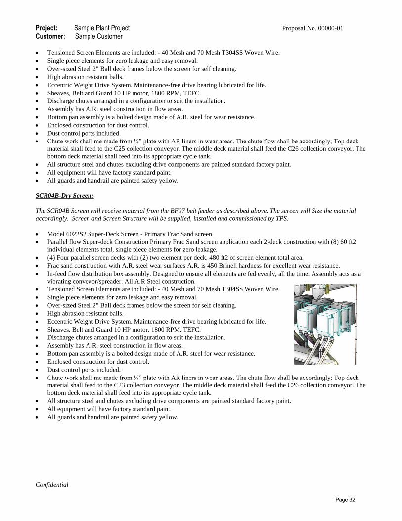
Project: Sample Plant Project Proposal No. 00000-01 Customer: Sample Customer
Confidential
Tensioned Screen Elements are included: - 40 Mesh and 70 Mesh T304SS Woven Wire.
Single piece elements for zero leakage and easy removal.
Over-sized Steel 2" Ball deck frames below the screen for self cleaning.
High abrasion resistant balls.
Eccentric Weight Drive System. Maintenance-free drive bearing lubricated for life.
Sheaves, Belt and Guard 10 HP motor, 1800 RPM, TEFC.
Discharge chutes arranged in a configuration to suit the installation.
Assembly has A.R. steel construction in flow areas.
Bottom pan assembly is a bolted design made of A.R. steel for wear resistance.
Enclosed construction for dust control.
Dust control ports included.
Chute work shall me made from ¼” plate with AR liners in wear areas. The chute flow shall be accordingly; Top deck
material shall feed to the C25 collection conveyor. The middle deck material shall feed the C26 collection conveyor. The
bottom deck material shall feed into its appropriate cycle tank.
All structure steel and chutes excluding drive components are painted standard factory paint.
All equipment will have factory standard paint.
All guards and handrail are painted safety yellow.
SCR04B-Dry Screen:
The SCR04B Screen will receive material from the BF07 belt feeder as described above. The screen will Size the material
accordingly. Screen and Screen Structure will be supplied, installed and commissioned by TPS.
Model 6022S2 Super-Deck Screen - Primary Frac Sand screen.
Parallel flow Super-deck Construction Primary Frac Sand screen application each 2-deck construction with (8) 60 ft2
individual elements total, single piece elements for zero leakage.
(4) Four parallel screen decks with (2) two element per deck. 480 ft2 of screen element total area.
Frac sand construction with A.R. steel wear surfaces A.R. is 450 Brinell hardness for excellent wear resistance.
In-feed flow distribution box assembly. Designed to ensure all elements are fed evenly, all the time. Assembly acts as a
vibrating conveyor/spreader. All A.R Steel construction.
Tensioned Screen Elements are included: - 40 Mesh and 70 Mesh T304SS Woven Wire.
Single piece elements for zero leakage and easy removal.
Over-sized Steel 2" Ball deck frames below the screen for self cleaning.
High abrasion resistant balls.
Eccentric Weight Drive System. Maintenance-free drive bearing lubricated for life.
Sheaves, Belt and Guard 10 HP motor, 1800 RPM, TEFC.
Discharge chutes arranged in a configuration to suit the installation.
Assembly has A.R. steel construction in flow areas.
Bottom pan assembly is a bolted design made of A.R. steel for wear resistance.
Enclosed construction for dust control.
Dust control ports included.
Chute work shall me made from ¼” plate with AR liners in wear areas. The chute flow shall be accordingly; Top deck
material shall feed to the C23 collection conveyor. The middle deck material shall feed the C26 collection conveyor. The
bottom deck material shall feed into its appropriate cycle tank.
All structure steel and chutes excluding drive components are painted standard factory paint.
All equipment will have factory standard paint.
All guards and handrail are painted safety yellow.
Page 32

Project: Sample Plant Project Proposal No. 00000-01 Customer: Sample Customer
Confidential
C23 -Conveyor
The conveyor will transfer material discharging from the both the primary dry screens. The material placed on this conveyor
will be fed into the BC01 bucket elevator. The conveyor supply, install and commissioning will be by TPS.
1ea. 24” x 52’ (60cm x 15.8m) Channel frame Conveyor.
Heavy Duty channel Conveyor Frame made using 8” channel.
Shaft mounted Gear Reducer with Internal Backstop.
5 HP.1800 RPM TEFC Electric motor. Drive Sheaves and belts are enclosed in a Drive Guard.
350 FPM average belt speed.
18” dia. Lagged Drive- Mine Duty type pulley, Hubs & Pillow block bearings.
Heavy Duty Shafting.
Replaceable blade Primary Cleaner.
Replaceable blade Secondary Cleaner.
18” dia. Wing type Tail- Mine Duty type pulley, Hubs & Pillow block bearings.
Heavy Duty Shafting.
Receiving hopper complete with rubber skirts and nip guards.
V-plow near the tail pulley and take-up pulley
Manual Screw Take-up.
CEMA-C 5” 20/35 deg, Troughing Idlers located at transitions (head and Tail).
CEMA-C 5” 45 deg, Troughing Idlers spaced on 4’-0” centers.
CEMA-C 5” Return Idlers spaced on 10’-0” centers. Include PPI Return guards on all return idlers.
Zero speed Switch.
Heat resistant 3 PLY. 330 P.I.W. belting with 3/16" top and 1/16" bottom covers, vulcanized splice.
Galvanized hinged hood cover in 4' sections.
Supports in screen structure steel.
Discharge hood made from 1/2” plate with bolt in A.R. liner in wear areas. Discharge hood shall be made to feed onto
the bucket elevator.
Conveyor and steel accessories excluding drive components are painted standard factory paint.
Tail pulley cover, all nip guards and handrail are painted safety yellow.
BE01 –Bucket Elevator
The Bucket elevator will transfer material discharging from the C23 conveyor. The material placed on this elevator will be
fed into the SCR05. The elevator supply, install and commissioning will be by TPS.
1ea. 12" x 7" x 68' (30.4cm x 17.7cm x 20.2m) bucket elevators.
11 gauge intermediate sections x 20' high with flanged joints and ribbed stiffeners.
Shaft mounted Gear Reducer with Internal Backstop.
25 HP.1800 RPM TEFC Electric motor. Drive Sheaves and belts are enclosed in a Drive Guard.
350 FPM average belt speed.
18” dia. Lagged Drive- Mine Duty type pulley, Hubs & Pillow block bearings.
Heavy Duty Shafting.
18” dia. Tail- Mine Duty type pulley, Hubs & Pillow block bearings.
Heavy Duty Shafting.
Manual Screw Take-up.
3/16" steel plate construction at the discharge end.
3/16" steel plate construction at the tail end.
Large removable access section at the tail pulley.
12" x 7" inlet with feed hopper. (3/16" plate construction).
14 gauge dust hood / bonnet a the discharge pulley.
Service platform around head end (3 sided).
Ladder and safety cage. With access to roof.
Page 33

Project: Sample Plant Project Proposal No. 00000-01 Customer: Sample Customer
Confidential
Supports in screen structure steel.
Elevator and steel accessories excluding drive components are painted standard factory paint.
Tail pulley cover, all nip guards and handrail are painted safety yellow.
SCR05-Dry Screen:
The SCR05 Screen will receive material from the BE01 elevator as described above. The screen will Size the material
accordingly. Screen and Screen Structure will be supplied, installed and commissioned by TPS.
Model 6022S2 Super-Deck Screen – Secondary Frac Sand screen.
Parallel flow Super-deck Construction Secondary Frac Sand screen application each 2-deck construction with (8) 60 ft2
individual elements total, single piece elements for zero leakage.
(4) Four parallel screen decks with (2) two element per deck. 480 ft2 of screen element total area.
Frac sand construction with A.R. steel wear surfaces A.R. is 450 Brinell hardness for excellent wear resistance.
In-feed flow distribution box assembly. Designed to ensure all elements are fed evenly, all the time. Assembly acts as a
vibrating conveyor/spreader. All A.R Steel construction.
Tensioned Screen Elements are included: - 20 Mesh and 40 Mesh T304SS Woven Wire.
Single piece elements for zero leakage and easy removal.
Over-sized Steel 2" Ball deck frames below the screen for self cleaning.
High abrasion resistant balls.
Eccentric Weight Drive System. Maintenance-free drive bearing lubricated for life.
Sheaves, Belt and Guard 10 HP motor, 1800 RPM, TEFC.
Discharge chutes arranged in a configuration to suit the installation.
Assembly has A.R. steel construction in flow areas.
Bottom pan assembly is a bolted design made of A.R. steel for wear resistance.
Enclosed construction for dust control.
Dust control ports included.
Chute work shall me made from ¼” plate with AR liners in wear areas. The chute flow shall be accordingly; Top deck
material shall feed to the BE02 elevator. The middle deck material shall feed ether the C24 conveyor or the SC03 screw
conveyor. The bottom deck material shall feed into its appropriate cycle tank.
All structure steel and chutes excluding drive components are painted standard factory paint.
All equipment will have factory standard paint.
All guards and handrail are painted safety yellow.
BE02 –Bucket Elevator
The Bucket elevator will transfer material discharging from the secondary screen top deck chute. The material placed on this
elevator will be fed into the Magnetic Separator supplied by the customer. The elevator supply, install and commissioning
will be by TPS.
1ea. 12" x 7" x 45' (30.4cm x 17.7cm x 13.7m) bucket elevators.
11 gauge intermediate sections x 20' high with flanged joints and ribbed stiffeners.
Shaft mounted Gear Reducer with Internal Backstop.
15 HP.1800 RPM TEFC Electric motor. Drive Sheaves and belts are enclosed in a Drive Guard.
350 FPM average belt speed.
18” dia. Lagged Drive- Mine Duty type pulley, Hubs & Pillow block bearings.
Heavy Duty Shafting.
18” dia. Tail- Mine Duty type pulley, Hubs & Pillow block bearings.
Heavy Duty Shafting.
Manual Screw Take-up.
3/16" steel plate construction at the discharge end.
3/16" steel plate construction at the tail end.
Large removable access section at the tail pulley.
Page 34

Project: Sample Plant Project Proposal No. 00000-01 Customer: Sample Customer
Confidential
12" x 7" inlet with feed hopper. (3/16" plate construction).
14 gauge dust hood / bonnet at the discharge pulley.
Service platform around head end (3 sided).
Ladder and safety cage. With access to roof access area.
Supports in screen structure steel.
Elevator and steel accessories excluding drive components are painted standard factory paint.
Tail pulley cover, all nip guards and handrail are painted safety yellow.
C24-Conveyor
The conveyor will transfer material discharging from the oversize cycle tank. The material placed on this conveyor will be
fed onto the OT01 Tank. The conveyor supply, install and commissioning will be by TPS.
1ea. 24” x 185’ (60cm x 56.3m) Truss frame Conveyor.
Heavy Duty Truss Conveyor Frame made using ¼” x 3” x 4” Cord Angle.
Shaft mounted Gear Reducer with Internal Backstop.
25 HP.1800 RPM TEFC Electric motor. Drive Sheaves and belts are enclosed in a Drive Guard.
350 FPM average belt speed.
20” dia. Lagged Drive- Mine Duty type pulley, Hubs & Pillow block bearings.
Heavy Duty Shafting.
18” dia. Wing type Tail- Mine Duty type pulley, Hubs & Pillow block bearings.
Heavy Duty Shafting.
Receiving hopper complete with rubber skirts and nip guards.
V-plow near the tail pulley and take-up pulley
Gravity Take-up vertical type Take-up frame including Weight Box and perimeter guarding.
18” dia. plain type Bends- Mine Duty type pulley, Hubs & Pillow block bearings.
Heavy Duty Shafting.
18” dia. wing type plain type Take-up- Mine Duty type pulley, Hubs & Pillow block bearings.
CEMA-C 5” 20/35 deg, Troughing Idlers located at transitions (head and Tail).
CEMA-C 5” 45 deg, Troughing Idlers spaced on 4’-0” centers.
CEMA-C 5” Return Idlers spaced on 10’-0” centers. Include PPI Return guards on all return idlers.
Zero speed Switch.
Heat resistant 3 PLY. 330 P.I.W. belting with 3/16" top and 1/16" bottom covers, vulcanized splice.
Galvanized hinged hood cover in 4' sections.
Supports on 40 ft spacing Supports are H-frame and A-frame type made using heavy-duty channel angle iron.
Discharge hood made from 1/2” plate with bolt in A.R. liner in wear areas. Discharge hood shall be made to feed onto
the OT01 Tank.
2 ft. wide Gripstrut type walkways including 1 ¼” dia. Pipe handrails, Angle type walkway supports and safety pull
cords and switches. Includes stair access to grade.
Conveyor and steel accessories excluding drive components are painted standard factory paint.
Tail pulley cover, all nip guards and handrail are painted safety yellow.
SC03 –Screw Conveyor
The screw conveyor will transfer material discharging from the above oversize cycle tank. The material placed in this screw
conveyor will be fed onto the C27 cycle collection conveyor. The screw conveyor supply, install and commissioning will be
by TPS.
1ea. 12” x 25’ (30.4cm x 7.6m) Screw Conveyor.
Fabricated from 14" diameter tube housing with hanger bearings on 12' centers.
5'-0" half pitch flighting at the feed end and the balance of Flighting is full pitch.
Flighting is 12" helicoids with 3/16" tip x 3/8" base fabricated from mild steel.
Screw mounted on 3" schedule 40 pipe with 2.4375" coupling and stub shaft.
Page 35

Project: Sample Plant Project Proposal No. 00000-01 Customer: Sample Customer
Confidential
12.75" diameter inlet pipe with bolting flange.
12.75" diameter discharge outlet pipe x 12" long.
Shaft mounted Gear Reducer with Internal Backstop.
5 HP.1800 RPM TEFC Electric motor. Drive Sheaves and belts are enclosed in a Drive Guard.
Screw conveyor and steel accessories excluding drive components are painted standard factory paint.
Tail pulley cover, all nip guards and handrail are painted safety yellow.
OT01 Oversize Tank.
The oversize tank shall receive material discharging from theC24 conveyor. The material will be feed ether to the CR04
crusher or can discharge into a truck for sales of removal from the system. Tank supply, install and commissioning will be by
TPS.
Tank is made from rolled steel with a diameter of 12’.
45 deg hopper slope terminating with a 14” dia flanged outlet.
Diverter chute with gate. Allows for feed to crusher or feed to the screw conveyor.
Hopper shall be supported using structural steel members bolted to the concrete footings with enough clearance for a
truck to drive through.
All structure steel and chutes are painted standard factory paint.
All equipment will have factory standard paint.
All guards and handrail are painted safety yellow.
CR04- VSI Crusher and support structure.
The VSI crusher will accept feed from the above OT01 tank. The crusher is supplied by the customer. Crusher rebuild, chutes
and structure supply, installation and commissioning will be by TPS.
Existing Vertical Shaft Impact Crusher.
The structure shall be made to support the Crusher. Heavy-duty crusher support structure made to fit the REMco
SandMax crusher. Support includes access platform around three sides of crusher including stair access from ground to
the crusher area and up to the screen area. The above shall be supported using structural steel members bolted to the
concrete footings.
Crusher discharge chute made from 3/8” plate steel with rock on rock design. Chute made to accept feed from the
crusher and direct the material onto the C25 conveyor.
All structure steel and chutes excluding drive components are painted standard factory paint.
All equipment will have factory standard paint.
All guards and handrail are painted safety yellow.
C25-Conveyor
The conveyor will transfer material discharging from the CR04 crusher. The material placed on this conveyor will be fed
onto the C22 conveyor for re-feed to the dry screens. The conveyor supply, install and commissioning will be by TPS.
1ea. 24” x 90’ (60cm x 27.4m) Truss frame Conveyor.
Heavy Duty Truss Conveyor Frame made using ¼” x 3” x 4” Cord Angle.
Shaft mounted Gear Reducer with Internal Backstop.
15 HP.1800 RPM TEFC Electric motor. Drive Sheaves and belts are enclosed in a Drive Guard.
350 FPM average belt speed.
18” dia. Lagged Drive- Mine Duty type pulley, Hubs & Pillow block bearings.
Heavy Duty Shafting.
18” dia. Wing type Tail- Mine Duty type pulley, Hubs & Pillow block bearings.
Heavy Duty Shafting.
Receiving hopper complete with rubber skirts and nip guards.
V-plow near the tail pulley and take-up pulley
Page 36

Project: Sample Plant Project Proposal No. 00000-01 Customer: Sample Customer
Confidential
Gravity Take-up vertical type Take-up frame including Weight Box and perimeter guarding.
18” dia. plain type Bends- Mine Duty type pulley, Hubs & Pillow block bearings.
Heavy Duty Shafting.
18” dia. wing type plain type Take-up- Mine Duty type pulley, Hubs & Pillow block bearings.
CEMA-C 5” 20/35 deg, Troughing Idlers located at transitions (head and Tail).
CEMA-C 5” 45 deg, Troughing Idlers spaced on 4’-0” centers.
CEMA-C 5” Return Idlers spaced on 10’-0” centers. Include PPI Return guards on all return idlers.
Zero speed Switch.
Heat resistant 3 PLY. 330 P.I.W. belting with 3/16" top and 1/16" bottom covers, vulcanized splice.
Galvanized hinged hood cover in 4' sections.
Supports on 40 ft spacing Supports are H-frame and A-frame type made using heavy-duty channel angle iron.
Discharge hood made from 1/2” plate with bolt in A.R. liner in wear areas. Discharge hood shall be made to feed onto
the C22 conveyor.
2 ft. wide Gripstrut type walkways including 1 ¼” dia. Pipe handrails, Angle type walkway supports and safety pull
cords and switches. Includes stair access to grade.
Conveyor and steel accessories excluding drive components are painted standard factory paint.
Tail pulley cover, all nip guards and handrail are painted safety yellow.
C26 -Conveyor
The conveyor will transfer material discharging from the both the primary dry screens. The material placed on this conveyor
will be fed into the BC03 bucket elevator. The conveyor supply, install and commissioning will be by TPS.
1ea. 24” x 52’ (60cm x 15.8m) Channel frame Conveyor.
Heavy Duty channel Conveyor Frame made using 8” channel.
Shaft mounted Gear Reducer with Internal Backstop.
5 HP.1800 RPM TEFC Electric motor. Drive Sheaves and belts are enclosed in a Drive Guard.
350 FPM average belt speed.
18” dia. Lagged Drive- Mine Duty type pulley, Hubs & Pillow block bearings.
Heavy Duty Shafting.
Replaceable blade Primary Cleaner.
Replaceable blade Secondary Cleaner.
18” dia. Wing type Tail- Mine Duty type pulley, Hubs & Pillow block bearings.
Heavy Duty Shafting.
Receiving hopper complete with rubber skirts and nip guards.
V-plow near the tail pulley and take-up pulley
Manual Screw Take-up.
CEMA-C 5” 20/35 deg, Troughing Idlers located at transitions (head and Tail).
CEMA-C 5” 45 deg, Troughing Idlers spaced on 4’-0” centers.
CEMA-C 5” Return Idlers spaced on 10’-0” centers. Include PPI Return guards on all return idlers.
Zero speed Switch.
Heat resistant 3 PLY. 330 P.I.W. belting with 3/16" top and 1/16" bottom covers, vulcanized splice.
Galvanized hinged hood cover in 4' sections.
Supports in screen structure steel.
Discharge hood made from 1/2” plate with bolt in A.R. liner in wear areas. Discharge hood shall be made to feed onto
the bucket elevator.
Conveyor and steel accessories excluding drive components are painted standard factory paint.
Tail pulley cover, all nip guards and handrail are painted safety yellow.
Page 37

Project: Sample Plant Project Proposal No. 00000-01 Customer: Sample Customer
Confidential
BE03 –Bucket Elevator
The Bucket elevator will transfer material discharging from the C26 conveyor. The material placed on this elevator will be
fed into the SCR06. The elevator supply, install and commissioning will be by TPS.
1ea. 12" x 7" x 68' (30.4cm x 17.7cm x 20.2m) bucket elevators.
11 gauge intermediate sections x 20' high with flanged joints and ribbed stiffeners.
Shaft mounted Gear Reducer with Internal Backstop.
25 HP.1800 RPM TEFC Electric motor. Drive Sheaves and belts are enclosed in a Drive Guard.
350 FPM average belt speed.
18” dia. Lagged Drive- Mine Duty type pulley, Hubs & Pillow block bearings.
Heavy Duty Shafting.
18” dia. Tail- Mine Duty type pulley, Hubs & Pillow block bearings.
Heavy Duty Shafting.
Manual Screw Take-up.
3/16" steel plate construction at the discharge end.
3/16" steel plate construction at the tail end.
Large removable access section at the tail pulley.
12" x 7" inlet with feed hopper. (3/16" plate construction).
14 gauge dust hood / bonnet at the discharge pulley.
Service platform around head end (3 sided).
Ladder and safety cage. With access to roof access area.
Supports in screen structure steel.
Elevator and steel accessories excluding drive components are painted standard factory paint.
Tail pulley cover, all nip guards and handrail are painted safety yellow.
SCR06-Dry Screen:
The SCR06 Screen will receive material from the BE03 elevator as described above. The screen will Size the material
accordingly. Screen and Screen Structure will be supplied, installed and commissioned by TPS.
Model 6033S1 Super-Deck Screen –Polishing Frac Sand screen.
Parallel flow Super-deck Construction Polishing Frac Sand screen application each 2-deck construction with (8) 60 ft2
individual elements total, single piece elements for zero leakage.
(6) Six parallel screen decks with (1) one element per deck. 360 ft2 of screen element total area.
Frac sand construction with A.R. steel wear surfaces A.R. is 450 Brinell hardness for excellent wear resistance.
In-feed flow distribution box assembly. Designed to ensure all elements are fed evenly, all the time. Assembly acts as a
vibrating conveyor/spreader. All A.R Steel construction.
Tensioned Screen Elements are included: - 70 Mesh T304SS Woven Wire.
Single piece elements for zero leakage and easy removal.
Over-sized Steel 2" Ball deck frames below the screen for self cleaning.
High abrasion resistant balls.
Eccentric Weight Drive System. Maintenance-free drive bearing lubricated for life.
Sheaves, Belt and Guard 10 HP motor, 1800 RPM, TEFC.
Discharge chutes arranged in a configuration to suit the installation.
Assembly has A.R. steel construction in flow areas.
Bottom pan assembly is a bolted design made of A.R. steel for wear resistance.
Enclosed construction for dust control.
Dust control ports included.
Chute work shall me made from ¼” plate with AR liners in wear areas. The chute flow shall be accordingly; Top deck
material shall feed into its appropriate cycle tank. The bottom deck material shall feed into its appropriate cycle tank.
All structure steel and chutes excluding drive components are painted standard factory paint.
All equipment will have factory standard paint.
Page 38

Project: Sample Plant Project Proposal No. 00000-01 Customer: Sample Customer
Confidential
All guards and handrail are painted safety yellow.
Cycle Tanks.
The Cycle tanks are used to hold material discharging from the dry screens until the automation system is ready to cycle the
product up into the storage/load out tanks. The cycle tanks also allow for blending products together and feed it into the
batch tank for loadout. The cycle tanks are made up of seven tanks each with the ability to discharge onto the C27 conveyor
for transport to the storage/load out area. Tanks supply, install and commissioning will be by TPS.
2ea 40/70 Tanks is made from rolled steel with a diameter of 9’.
45 deg hopper slope terminating with a 14” dia flanged outlet.
Hopper shall be supported using structural steel members bolted to the concrete footings.
2ea 100mesh Tanks are made from rolled steel with a diameter of 9’.
45 deg hopper slope terminating with a 14” dia flanged outlet.
Hopper shall be supported using structural steel members bolted to the concrete footings.
1ea 100mesh Tank is made from rolled steel with a diameter of 9’.
45 deg hopper slope terminating with a 14” dia flanged outlet.
Hopper shall be supported using structural steel members bolted to the concrete footings.
1ea 20/40 Tank is made from rolled steel with a diameter of 9’.
45 deg hopper slope terminating with a 14” dia flanged outlet.
Hopper shall be supported using structural steel members bolted to the concrete footings.
1ea +20 Tank is made from rolled steel with a diameter of 9’.
45 deg hopper slope terminating with a 14” dia flanged outlet.
Hopper shall be supported using structural steel members bolted to the concrete footings
All structure steel and Tanks are painted standard factory paint.
All equipment will have factory standard paint.
All guards and handrail are painted safety yellow.
Storage/Loadout Scope and Descriptions.
C27 -Conveyor
The conveyor will transfer material discharging from above cycle tanks. The material placed on this conveyor will be fed into
the C28 conveyor. The conveyor supply, install and commissioning will be by TPS.
1ea. 42” x 82’ (106cm x 24.9m) Channel frame Conveyor.
Heavy Duty channel Conveyor Frame made using 8” channel.
Shaft mounted Gear Reducer with Internal Backstop.
15 HP.1800 RPM TEFC Electric motor. Drive Sheaves and belts are enclosed in a Drive Guard.
350 FPM average belt speed.
18” dia. Lagged Drive- Mine Duty type pulley, Hubs & Pillow block bearings.
Heavy Duty Shafting.
Replaceable blade Primary Cleaner.
Replaceable blade Secondary Cleaner.
18” dia. Wing type Tail- Mine Duty type pulley, Hubs & Pillow block bearings.
Heavy Duty Shafting.
Receiving hopper complete with rubber skirts and nip guards.
V-plow near the tail pulley and take-up pulley
Manual Screw Take-up.
CEMA-C 5” 20/35 deg, Troughing Idlers located at transitions (head and Tail).
CEMA-C 5” 45 deg, Troughing Idlers spaced on 4’-0” centers.
CEMA-C 5” Return Idlers spaced on 10’-0” centers. Include PPI Return guards on all return idlers.
Zero speed Switch.
Page 39

Project: Sample Plant Project Proposal No. 00000-01 Customer: Sample Customer
Confidential
Heat resistant 3 PLY. 330 P.I.W. belting with 3/16" top and 1/16" bottom covers, vulcanized splice.
Galvanized hinged hood cover in 4' sections.
Supports in screen structure steel.
Discharge hood made from 1/2” plate with bolt in A.R. liner in wear areas. Discharge hood shall be made to feed onto
the next conveyor.
Conveyor and steel accessories excluding drive components are painted standard factory paint.
Tail pulley cover, all nip guards and handrail are painted safety yellow.
C28 -Conveyor
The conveyor will transfer material discharging from the C27 conveyor. The material placed on this conveyor will be fed into
the C29 conveyor. The conveyor supply, install and commissioning will be by TPS.
1ea. 42” x 50’ (106cm x 15.2m ) Channel frame Conveyor.
Heavy Duty channel Conveyor Frame made using 8” channel.
Shaft mounted Gear Reducer with Internal Backstop.
15 HP.1800 RPM TEFC Electric motor. Drive Sheaves and belts are enclosed in a Drive Guard.
350 FPM average belt speed.
18” dia. Lagged Drive- Mine Duty type pulley, Hubs & Pillow block bearings.
Heavy Duty Shafting.
Replaceable blade Primary Cleaner.
Replaceable blade Secondary Cleaner.
18” dia. Wing type Tail- Mine Duty type pulley, Hubs & Pillow block bearings.
Heavy Duty Shafting.
Receiving hopper complete with rubber skirts and nip guards.
V-plow near the tail pulley and take-up pulley
Manual Screw Take-up.
CEMA-C 5” 20/35 deg, Troughing Idlers located at transitions (head and Tail).
CEMA-C 5” 45 deg, Troughing Idlers spaced on 4’-0” centers.
CEMA-C 5” Return Idlers spaced on 10’-0” centers. Include PPI Return guards on all return idlers.
Zero speed Switch.
Heat resistant 3 PLY. 330 P.I.W. belting with 3/16" top and 1/16" bottom covers, vulcanized splice.
Galvanized hinged hood cover in 4' sections.
Supports on 20 ft spacing Supports are H-frame and A-frame type made using heavy-duty channel angle iron.
Discharge hood made from 1/2” plate with bolt in A.R. liner in wear areas. Discharge hood shall be made to feed onto
the next conveyor.
Conveyor and steel accessories excluding drive components are painted standard factory paint.
Tail pulley cover, all nip guards and handrail are painted safety yellow.
SP07 –Two Way Splitter Chute:
The splitter chute will transfer material from the C28 Conveyor and will have split by % onto the C29 stacker conveyor or
onto the C30 conveyor. Chute will be supplied, installed and commissioned by TPS.
The two way splitter chute is made from 3/8” plate with bolt in A.R. liner in wear areas. Discharge chute shall be made
to feed and distribute material into the C29 stacker conveyor or C30 conveyor with a flop gate type control. Chute shall
include a heavy duty support structure with walkway access around three sides and access to grade.
All structure steel and chutes excluding drive components are painted standard factory paint.
All equipment will have factory standard paint.
All guards and handrail are painted safety yellow.
Page 40

Project: Sample Plant Project Proposal No. 00000-01 Customer: Sample Customer
Confidential
C29 –Stacking Conveyor
The stacking conveyor will transfer material discharging from the SP07 Splitter Chute. The material placed on this conveyor
will be stockpiled or put into a truck. The conveyor supply, install and commissioning will be by TPS.
1ea. 36” x 75’ (91cm x 22.8m) Stacking Conveyor.
Heavy Duty Truss Conveyor Frame made using ¼” x 4” x 4” Cord Angle.
Shaft mounted Gear Reducer with Internal Backstop.
15 HP.1800 RPM TEFC Electric motor. Drive Sheaves and belts are enclosed in a Drive Guard.
350 FPM average belt speed.
18” dia. Lagged Drive- MD pulley, Hubs & Pillow block bearings.
Heavy Duty Shafting.
Replaceable blade Primary Cleaner.
Replaceable blade Secondary Cleaner.
16” dia. Snub- MD pulley, Hubs & Pillow block bearings.
Heavy Duty Shafting.
16” dia. Wing type Tail- MD pulley, Hubs & Pillow block bearings.
Heavy Duty Shafting.
V-plow near the tail pulley and take-up pulley
Manual Screw Take-up.
CEMA-C 5” 20 deg, Troughing Idlers located at transitions (head and Tail).
CEMA-C 5” 35 deg, Troughing Idlers spaced on 3’-6” centers.
CEMA-C 5” Return Idlers spaced on 10’-0” centers.
Zero Speed Switch.
Heat resistant 3 PLY. 330 P.I.W. belting with 3/16" top and 1/16" bottom covers, vulcanized splice.
Galvanized hinged hood cover in 4' sections.
Heavy duty undercarriage made from square tubing and includes heavy duty telescoping axle with swivel boxes, 11.22.5
tires and wheels with Manual up and down.
Anchor pivot plate, maintains tail end during radial travel.
Manual Up and Down and Travel.
Conveyor and steel accessories excluding drive components are painted standard factory paint.
Tail pulley cover, all nip guards and handrail are painted safety yellow.
C30-Conveyor
The conveyor will transfer material discharging from the above SP07 splitter. The material placed on this conveyor will be
fed up to the storage /load out tanks. The conveyor supply, install and commissioning will be by TPS.
1ea. 42” x 345’ (106cm x 105.1m )Truss frame Conveyor.
Heavy Duty Truss Conveyor Frame made using ¼” x 3” x 4” Cord Angle.
Shaft mounted Gear Reducer with Internal Backstop.
75 HP.1800 RPM TEFC Electric motor. Drive Sheaves and belts are enclosed in a Drive Guard.
350 FPM average belt speed.
30” dia. Lagged Drive- Mine Duty type pulley, Hubs & Pillow block bearings.
Heavy Duty Shafting.
Replaceable blade Primary Cleaner.
Replaceable blade Secondary Cleaner.
4” dia. Wing type Tail- Mine Duty type pulley, Hubs & Pillow block bearings.
Heavy Duty Shafting.
Receiving hopper complete with rubber skirts and nip guards.
V-plow near the tail pulley and take-up pulley
Gravity Take-up vertical type Take-up frame including Weight Box and perimeter guarding.
Page 41

Project: Sample Plant Project Proposal No. 00000-01 Customer: Sample Customer
Confidential
24” dia. plain type Bends- Mine Duty type pulley, Hubs & Pillow block bearings.
Heavy Duty Shafting.
24” dia. wing type plain type Take-up- Mine Duty type pulley, Hubs & Pillow block bearings.
CEMA-C 5” 20/35 deg, Troughing Idlers located at transitions (head and Tail).
CEMA-C 5” 45 deg, Troughing Idlers spaced on 4’-0” centers.
CEMA-C 5” Return Idlers spaced on 10’-0” centers. Include PPI Return guards on all return idlers.
Zero speed Switch.
Heat resistant 3 PLY. 330 P.I.W. belting with 3/16" top and 1/16" bottom covers, vulcanized splice.
Galvanized hinged hood cover in 4' sections.
Supports on 40 ft spacing Supports are H-frame and A-frame type made using heavy-duty channel angle iron.
Discharge hood made from 1/2” plate with bolt in A.R. liner in wear areas. Discharge hood shall be made to feed onto
the SP08 splitter.
2 ft. wide Gripstrut type walkways including 1 ¼” dia. Pipe handrails, Angle type walkway supports and safety pull
cords and switches. Includes stair access to grade.
Conveyor and steel accessories excluding drive components are painted standard factory paint.
Tail pulley cover, all nip guards and handrail are painted safety yellow.
SP08 –Three Way Splitter Chute:
The splitter chute will transfer material from the C30 Conveyor and will have split by % onto the C31 conveyor or into the
batch tank or the 40/70 tank for load out on the truck system or the rail system. Chute will be supplied, installed and
commissioned by TPS.
The three way splitter chute is made from 3/8” plate with bolt in A.R. liner in wear areas. Discharge chute shall be made
to feed and distribute material into the C31 conveyor or the batch tank or the 40/70 tank with a flop gate type control.
Chute shall include a heavy duty support structure with walkway access around three sides and access to grade.
All structure steel and chutes excluding drive components are painted standard factory paint.
All equipment will have factory standard paint.
All guards and handrail are painted safety yellow.
C31 -Conveyor
The conveyor will transfer material discharging from theSP08 splitter. The material placed on this conveyor will be fed into
the100 mesh tank. The conveyor supply, install and commissioning will be by TPS.
1ea. 42” x 35’ (106cm x 10.6m ) Channel frame Conveyor.
Heavy Duty channel Conveyor Frame made using 8” channel.
Shaft mounted Gear Reducer with Internal Backstop.
5 HP.1800 RPM TEFC Electric motor. Drive Sheaves and belts are enclosed in a Drive Guard.
350 FPM average belt speed.
18” dia. Lagged Drive- Mine Duty type pulley, Hubs & Pillow block bearings.
Heavy Duty Shafting.
Replaceable blade Primary Cleaner.
Replaceable blade Secondary Cleaner.
18” dia. Wing type Tail- Mine Duty type pulley, Hubs & Pillow block bearings.
Heavy Duty Shafting.
Receiving hopper complete with rubber skirts and nip guards.
V-plow near the tail pulley and take-up pulley
Manual Screw Take-up.
CEMA-C 5” 20/35 deg, Troughing Idlers located at transitions (head and Tail).
CEMA-C 5” 45 deg, Troughing Idlers spaced on 4’-0” centers.
CEMA-C 5” Return Idlers spaced on 10’-0” centers. Include PPI Return guards on all return idlers.
Zero speed Switch.
Page 42

Project: Sample Plant Project Proposal No. 00000-01 Customer: Sample Customer
Confidential
Heat resistant 3 PLY. 330 P.I.W. belting with 3/16" top and 1/16" bottom covers, vulcanized splice.
Galvanized hinged hood cover in 4' sections.
Supports on top of the tanks.
Discharge hood made from 1/2” plate with bolt in A.R. liner in wear areas. Discharge hood shall be made to feed onto
the 100 mesh tank.
Conveyor and steel accessories excluding drive components are painted standard factory paint.
Tail pulley cover, all nip guards and handrail are painted safety yellow.
STK01-Batch Tank
The batch tank will accept feed from the splitter chute. The tank shall have a 500 tons capacity and hold blended products or
other specialty products staging for shipment. Tank can be unloaded by gravity type into a tank truck or sent to the rail car
loading system. The Tank supply, install and commissioning will be by TPS.
Tank is made from rolled steel with a diameter of 21’.
45 deg hopper slope terminating with a 14” dia flanged outlet.
Diverter chute with gate. Allows for feed to Truck or feed to the rail loadout collection conveyor.
Air vent filter Module.
Vent Exhaust Fan.
Filter Module, Loading Spout, Control Pendant, Manual Gate & Pneumatic Gate.
Wave Radar Level System & High Level Indicator.
Carbis Gangway.
Walkway inside tank.
Hopper shall be supported using structural steel members bolted to the concrete footings with enough clearance for a
truck to drive through.
All structure steel and chutes are painted standard factory paint.
All equipment will have factory standard paint.
All guards and handrail are painted safety yellow.
STK02-40/70 Tank
The 40/70 tank will accept feed from the splitter chute. The tank shall have a 1500 tonnes capacity and hold the 40/70
product staging it for shipment. Tank can be unloaded by gravity type into a tank truck or sent to the rail car loading system.
The Tank supply, install and commissioning will be by TPS.
Tank is made from rolled steel with a diameter of 29’.
45 deg hopper slope terminating with a 14” dia flanged outlet.
Diverter chute with gate. Allows for feed to Truck or feed to the rail loadout collection conveyor.
Air vent filter Module.
Vent Exhaust Fan.
Filter Module, Loading Spout, Control Pendant, Manual Gate & Pneumatic Gate.
Wave Radar Level System & High Level Indicator.
Carbis Gangway.
Walkway inside tank.
Hopper shall be supported using structural steel members bolted
to the concrete footings with enough clearance for a truck to drive through.
All structure steel and chutes are painted standard factory paint.
All equipment will have factory standard paint.
All guards and handrail are painted safety yellow.
Page 43

Project: Sample Plant Project Proposal No. 00000-01 Customer: Sample Customer
Confidential
STK03-100 mesh Tank
The 100 mesh tank will accept feed from the C31 conveyor. The tank shall have a 1500 tonnes capacity and hold the 100
mesh product staging it for shipment. Tank can be unloaded by gravity type into a tank truck or sent to the rail car loading
system. The Tank supply, install and commissioning will be by TPS.
Tank is made from rolled steel with a diameter of 29’.
45 deg hopper slope terminating with a 14” dia flanged outlet.
Diverter chute with gate. Allows for feed to Truck or feed to the rail loadout collection conveyor.
Air vent filter Module.
Vent Exhaust Fan.
Filter Module, Loading Spout, Control Pendant, Manual Gate & Pneumatic Gate.
Wave Radar Level System & High Level Indicator.
Carbis Gangway.
Walkway inside tank.
Hopper shall be supported using structural steel members bolted to the concrete footings with enough clearance for a
truck to drive through.
All structure steel and chutes are painted standard factory paint.
All equipment will have factory standard paint.
All guards and handrail are painted safety yellow.
TS01-Truck Scale System
The truck scale will be located underneath the three storage tanks described above. The scale system will provide truck
loadout ticketing. The truck scale system supply, install and commissioning will be by TPS.
1ea. Model 7562 120 FT Truckmate® Scale.
Heavy Duty channel Conveyor Frame made using 8” channel.
120’ Long X 11’ Wide.
Superior Orthotropic Steel Deck Design
80,000 Lb. Concentrated Load Capacity
200,000Lb. Scale Capacity
Minimum Increment Size, 20 Lb.
Ntep Cc: 93-108a3
Cycle Duty (Up To 250 Cycles Per Day, Average)
Factory Assembled Modules
Side rails and mounting brackets
300 ft Stainless Steel Sheathed Cables
Stainless Steel Junction Boxes
(10) 6” riser plates
Installation Kit Of Parts
5-Year Guarantee and Strikeshield Lightning Protection System.
45t Powercell® Mtx
® Load Cells
ADI310 Scoreboard to be mounted on load out
8’ x 8’ control room with ticket printer
Control room to tank loadout access.
C32-Conveyor
The conveyor will transfer material discharging from the any of the above storage tanks. The material placed on this
conveyor will be fed up to the Rail Car loadout System. The conveyor supply, install and commissioning will be by TPS.
1ea. 42” x 220’ (106cm x 67m) Truss frame Conveyor.
Heavy Duty Truss Conveyor Frame made using ¼” x 3” x 4” Cord Angle.
Page 44

Project: Sample Plant Project Proposal No. 00000-01 Customer: Sample Customer
Confidential
Shaft mounted Gear Reducer with Internal Backstop.
50 HP.1800 RPM TEFC Electric motor. Drive Sheaves and belts are enclosed in a Drive Guard.
350 FPM average belt speed.
24” dia. Lagged Drive- Mine Duty type pulley, Hubs & Pillow block bearings.
Heavy Duty Shafting.
Replaceable blade Primary Cleaner.
Replaceable blade Secondary Cleaner.
24” dia. Wing type Tail- Mine Duty type pulley, Hubs & Pillow block bearings.
Heavy Duty Shafting.
Receiving hopper complete with rubber skirts and nip guards.
V-plow near the tail pulley and take-up pulley
Gravity Take-up vertical type Take-up frame including Weight Box and perimeter guarding.
24” dia. plain type Bends- Mine Duty type pulley, Hubs & Pillow block bearings.
Heavy Duty Shafting.
24” dia. wing type plain type Take-up- Mine Duty type pulley, Hubs & Pillow block bearings.
CEMA-C 5” 20/35 deg, Troughing Idlers located at transitions (head and Tail).
CEMA-C 5” 45 deg, Troughing Idlers spaced on 4’-0” centers.
CEMA-C 5” Return Idlers spaced on 10’-0” centers. Include PPI Return guards on all return idlers.
Zero speed Switch.
Heat resistant 3 PLY. 330 P.I.W. belting with 3/16" top and 1/16" bottom covers, vulcanized splice.
Galvanized hinged hood cover in 4' sections.
Supports on 40 ft spacing Supports are H-frame and A-frame type made using heavy-duty channel angle iron.
Discharge hood made from 1/2” plate with bolt in A.R. liner in wear areas. Discharge hood shall be made to feed onto
the rail car loading system.
Conveyor and steel accessories excluding drive components are painted standard factory paint.
Tail pulley cover, all nip guards and handrail are painted safety yellow.
Belt Scale.
The belt scale will be located on the C32 conveyor and produce a tonnage rate for rail car loading. The belt scale
supply, installation and commissioning will be by TPS.
Weighbridge: Three or four idler suspension-type Ramsey 10-14 weighbridges feature full-floating unitized
assemblies with no pivots and non-moving parts. All Ramsey weighbridges from Thermo are constructed of
structural steel tubing and are factory pre-assembled with check rods to facilitate fast and easy field installation.
Only eight bolts are required to mount the unit to conveyor stringers. Four environmentally-sealed precision
strain gauge loadcell assemblies are applied in tension to support the weighbridge.
The Belt Speed Sensor: Ramsey 61-12C Digital Belt Speed Sensor is the most reliable and accurate speed-
sensing device ever developed for belt scale service. Direct-coupling the sensor to the conveyor tail pulley,
snubbing roll, or a large diameter return roller ensures accurate belt-travel readout. No wheels ride on the belt,
which eliminates problems related to material build-up and slippage.
RL01- Rail Car Loading System
The loading system shall receive feed from the C32 conveyor. The product will be fed into chute with a discharge spout
acceptable to feeding a rail car. The system supply, install and commissioning will be by TPS.
45 deg hopper slope terminating with a 14” dia flanged outlet.
Air vent filter Module.
Vent Exhaust Fan.
Filter Module, Loading Spout, Control Pendant, Manual Gate & Pneumatic Gate.
Walkway access to top of train cars and to the chute transition area.
Page 45

Project: Sample Plant Project Proposal No. 00000-01 Customer: Sample Customer
Confidential
Above shall be supported using structural steel members bolted to the concrete footings with enough clearance for the
rail cars to roll through.
All structure steel and chutes are painted standard factory paint.
All equipment will have factory standard paint.
All guards and handrail are painted safety yellow.
Page 46

Sample Company II. Project Cost Report
Project: Sample Plant Site
Equipment Cost Actual Cost Breakdown
Equipment-Wet Plant $1,362,076
Equipment-Dry Plant $1,293,321
Equipment-Dust Control $303,037
Equipment-Storage/Loadout $998,911
Equipment-Buildings $80,000
Total $4,037,345
Conveyors CostConveyors -Wet Plant $1,509,571
Conveyors -Dry Plant $782,504
Conveyors -Storage/Loadout $473,587
Total $2,765,662
Structures CostStructures-Wet Plant $948,723
Structures-Dry Plant $752,794
Structures-Dust Control $20,000
Total $1,721,517
Concrete CostStructures Concrete $793,000
Conveyors Concrete $174,000
Concrete Embedment's $52,000
Total $1,019,000
Installation CostEquipment Rentals $204,000
Installation of Equipment, Structures $821,600
Belt Vulcanize and training $176,520
Total $1,202,120
Freight In CostFreight in on Equipment, Structures
and Conveyors $470,400
Total $470,400
Electrical Cost
$3,325,500
Total $3,325,500
Project Management Cost
Engineering, Procurement, Project Management $2,500,000
Total $2,500,000
Project Contingency Cost
$900,000
Project Contingency Total $900,000
Project Cost Cost
Total Project Cost $17,941,545
Processing Plant
All the right answers to your Processing Solutions
22%
15%
10%6%7%
3%
18%
14%5%
$17,941,545Equipment
Conveyors
Structures
Concrete
Installation
Freight In
Electrical
Project Management
Project Contingency
USD
Project Summary Confidential
Page 47

Sample Company Equipment Summary Processing Plant
Project: Sample Plant Site
Equipment-Wet Plant H.P. CostF01 Lippmann 51" X 20' Vibrating Grizzly Feeder 40 $35,600
CR01 Lippmann 30" x 48" Jaw Crusher 200 $210,510
AutoLube $7,050
Hydraulic Toggle $45,000
SCR01 5' x 16' Screen 30 $28,610
Media $15,000
CR02 Sandvik H4800 Cone Crusher $350,000
Main Drive Motor 300
Cooling fan (4.6kw) 10
Hydro-set (2.5kw)
Oil heater
Lube oil pump (3.4kw) 5
Over pressure blower (.45kw) 0.5
Pinion pump (.29kw) 0.5
SCR02A 8x20 Screen $112,358
Motor 1 30 $1,620
Motor 2 30 $1,620
Media $30,000
SCR02B 8x20 Screen $0
Motor 1 30 $0
Motor 2 30 $0
Media $0
FMW01A McLanahan Twin 44" x33' Fine Material Washer $82,231
Motor 1 15 $1,338
Motor 2 2 $1,338
Top Covers $11,562
Polyurethane wear shoes $4,954
FMW01B McLanahan Twin 44" x33' Fine Material Washer $0
Motor 1 15 $0
Motor 2 15 $0
Top Covers $0
Polyurethane wear shoes $0
UFR01 McLanahan Ultrafines Recovery Plant $144,495
Hydrocyclone Stack with 3 Model HSE1510B4
Feed Distributor
Dewatering Screen
Motor 1 4
Motor 2 4
Feed Collection Sump Box
Slurry Pump 150
Structure Package
CR03A REMco SandMax 800 ST $209,800
Dual Drive Assembly $9,975
Motor 1 400 $15,000
Motor 2 400 $15,000
Spare Rotor $13,900
Heat Exchanger $2,445
Lube Heat system $670
CR03B REMco SandMax 800 ST $0
Dual Drive Assembly $0
Motor 1 400 $0
Motor 2 400 $0
Spare Rotor $0
Heat Exchanger $0
Lube Heat system $0
SCR03 4' x 10' SD Screen 7.5 $12,000
Equipment-Wet Plant Total $1,362,076
Equipment Confidential ]
Page 48

Equipment-Dry Plant H.P. CostDR01 8' x 30' Counter Flow Dryer $247,292
Motor 1 20
Motor 2 20
Motor 3 20
Motor 4 20
Cyclone $25,949
Baghouse $145,368
FN01 Supply Fan 150
Duct Work..Includes Ducting, airlocks and etc.. $32,650
SCR04A 6022S2 BM&M Screen 10 $200,000
SCR04B 6022S2 BM&M Screen 10 $200,000
SCR05 6022S2 BM&M Screen 10 $200,000
SCR06 6033S1 BM&M Screen 10 $200,000
MGS01 Magnet Seperator………. supply by CUSTOMER $0
Motor 1 5
Motor 2 5
Motor 3 5
CR04 Rebuilt VSI…………....….supply by CUSTOMER 100 $42,062
Equipment-Dry Plant Total $1,293,321
Equipment-Dust Control H.P. CostBH01 Bag House $85,950
Duct Work..Includes Ducting, airlocks and etc.. $135,125
FN02 Exhaust Fan 300 $42,010
AC01 Air Compressor 60 $35,662
piping $4,290
Equipment-Dust Control Total $303,037
Equipment-Storage/Loadout H.P. CostSTK01 500 ton Storage Tank $115,695
Batch Air vent filter Module $7,094
Vent Exhaust Fan 5 $1,875
Product Filter Module, Loading Spout, Control Pendant, Manual Gate & Pneumatic Gate $31,477
Storage Wave Radar Level System & High Level Indicator $2,851
Carbis Gangway $8,820
Tank fittings $2,000
Walkway inside tank $4,000
STK02 1500 ton Storage Tank $270,310
40x70 Air vent filter Module $7,094
Vent Exhaust Fan 5 $1,875
Product Filter Module, Loading Spout, Control Pendant, Manual Gate & Pneumatic Gate $31,477
Storage Wave Radar Level System & High Level Indicator $2,851
Carbis Gangway $8,820
Tank fittings $2,000
Walkway inside tank $4,000
STK03 1500 ton Storage Tank $270,310
100 Mesh Air vent filter Module $7,094
Vent Exhaust Fan 5 $1,875
Product Filter Module, Loading Spout, Control Pendant, Manual Gate & Pneumatic Gate $31,477
Storage Wave Radar Level System & High Level Indicator $2,851
Carbis Gangway $8,820
Tank fittings $2,000
Walkway inside tank $4,000
RL01 Rail Loadout
Filter Module, Loading Spout, Control Pendant, Manual Gate & Pneumatic Gate $31,477
Wave Radar Level System & High Level Indicator $2,851
Carbis Gangway $8,820
TS01 Truck Scale and Ticketing Model 7562 150 FT Truckmate Scale $110,600
CH01 Ticketing Control House 8x8 $14,500
Equipment-Storage/Loadout $998,911
Equipment-Buildings H.P. CostOF01 24x56 Office Building $20,000
Warehouse $10,000
Equipment Confidential ]
Page 49
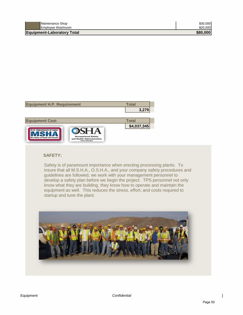
Maintenance Shop $30,000
Employee Washroom $20,000
Equipment-Laboratory Total $80,000
Equipment H.P. Requirement Total
3,279
Equipment Cost Total
$4,037,345
Safety is of paramount importance when erecting processing plants. To insure that all M.S.H.A., O.S.H.A., and your company safety procedures and guidelines are followed, we work with your management personnel to develop a safety plan before we begin the project. TPS personnel not only know what they are building, they know how to operate and maintain the equipment as well. This reduces the stress, effort, and costs required to startup and tune the plant.
SAFETY:
Equipment Confidential ]
Page 50

Sample Company Conveyor Summary
Processing PlantProject: Sample Plant Site ?
Conveyors -Wet Plant H.P. CostBF01 36" X 8' Belt Feeder 5 $20,689
BF02 36" X 8' Belt Feeder 5 $20,689
BF03 36" X 8' Belt Feeder 5 $20,689
BF04 36" X 8' Belt Feeder 5 $20,689
BF05 48" X 20' Belt Feeder 25 $31,800
C01 48" X 38' Belt Conveyor Channel Frame 20 $28,675
C02 48" x 120' Belt Conveyor Truss Frame 40 $69,344
C03 48" X 38' Belt Conveyor Channel Frame 20 $31,861
C04 36" x 120' Belt Conveyor Truss Frame 40 $66,239
C05 36" x 80' Belt Conveyor Channel Frame 5 $41,789
C06 36" x 110' Belt Conveyor Truss Frame 20 $64,948
C07 36" x 80' Belt Conveyor Channel Frame 5 $41,789
C08 36" x 100' Belt Conveyor Truss Frame 20 $64,578
C09 36" X 100' Belt Conveyor Channel/Truss Frame 20 $66,278
C10 36" x40' Belt Conveyor Channel Frame 5 $39,569
C11 36" x 80' Belt Conveyor Truss Frame 10 $44,272
C12 36" 150' Radial Stacker Telescoping 40 $165,450
Stinger 20
Power up & Down 10
Power travel 2
Winch 40
C13 36" X 100' Belt Conveyor Truss Frame Jumper 20 $38,472
C14 36" X 100' Belt Conveyor Truss Frame Jumper 20 $38,472
C15 36" X 100' Belt Conveyor Truss Frame Jumper 20 $38,472
C16 36" X 100' Belt Conveyor Truss Frame Jumper 20 $38,472
C17 36" 150' Radial Stacker Telescoping 40 $165,450
Stinger 20
Power up & Down 10
Power travel 2
Winch 40
C18 30" x 40' Belt Conveyor 5 $39,201
C19 30" x 75' Radial Stacker Truss Frame 15 $39,510
C20 36" X 350' Belt Conveyor Channel/Truss Frame 75 $223,918
C21 36" X 100' Belt Conveyor Truss Frame 25 $41,056
Belt Scale $7,200
Conveyors -Wet Plant Total $1,509,571
Conveyors -Dry Plant H.P. CostBF06 24" X 18' Belt Feeder 5 $25,011
BF07 24" X 18' Belt Feeder 5 $25,011
BE01 12 X 7 X 68' Bucket Elevator 25 $138,800
BE02 12 X 7 X 45' Bucket Elevator 15 $53,567
BE03 12 X 7 X 68' Bucket Elevator 25 $138,800
C22 30' X 285' Belt Conveyor Truss Frame 40 $178,917
C23 24" x 52' Belt Conveyor Channel Frame 5 $30,622
C24 24" x 185' Belt Conveyor Truss Frame 25 $105,244
C25 24" x 90' Belt Conveyor Truss Frame 15 $5,230
C26 24" x 52' Belt Conveyor Channel Frame 5 $30,622
C27 42" x 82' Belt Conveyor Channel Frame 15 $50,680
SC01 Screw Conveyor 5
SC02 Screw Conveyor 5
SC03 Screw Conveyor 5
Conveyors --Dry PlantTotal $782,504
Conveyors Confidential
Page 51
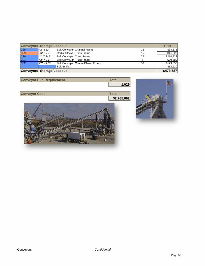
Conveyors -Storage/Loadout CostC28 42" x 50' Belt Conveyor Channel Frame 15 $34,678
C29 36" X 75' Radial Stacker Truss Frame 15 $41,623
C30 42' X 345' Belt Conveyor Truss Frame 75 $214,722
C31 42" X 35' Belt Conveyor Truss Frame 5 $20,389
C32 42" X 220' Belt Conveyor Channel/Truss Frame 50 $129,556
Belt Scale $32,620
Conveyors -Storage/Loadout $473,587
Conveyor H.P. Requirement Total
1,029
Conveyor Cost Total
$2,765,662
Conveyors Confidential
Page 52
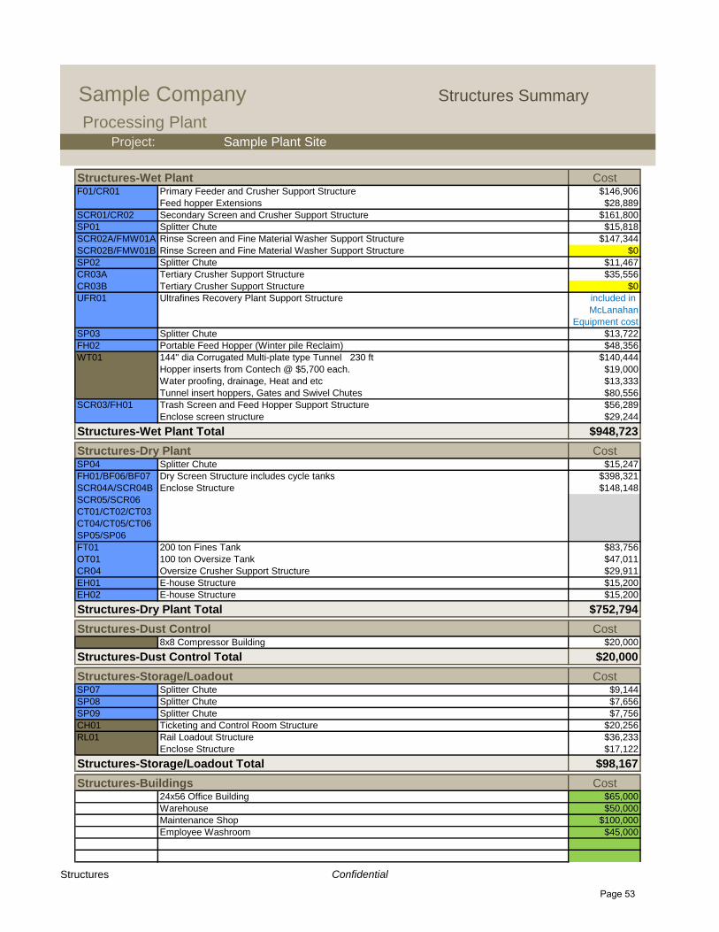
Sample Company Structures Summary
Processing PlantProject: Sample Plant Site
Structures-Wet Plant CostF01/CR01 Primary Feeder and Crusher Support Structure $146,906
Feed hopper Extensions $28,889
SCR01/CR02 Secondary Screen and Crusher Support Structure $161,800
SP01 Splitter Chute $15,818
SCR02A/FMW01A Rinse Screen and Fine Material Washer Support Structure $147,344
SCR02B/FMW01B Rinse Screen and Fine Material Washer Support Structure $0
SP02 Splitter Chute $11,467
CR03A Tertiary Crusher Support Structure $35,556
CR03B Tertiary Crusher Support Structure $0
UFR01 Ultrafines Recovery Plant Support Structure included in
McLanahan
Equipment cost
SP03 Splitter Chute $13,722
FH02 Portable Feed Hopper (Winter pile Reclaim) $48,356
WT01 144" dia Corrugated Multi-plate type Tunnel 230 ft $140,444
Hopper inserts from Contech @ $5,700 each. $19,000
Water proofing, drainage, Heat and etc $13,333
Tunnel insert hoppers, Gates and Swivel Chutes $80,556
SCR03/FH01 Trash Screen and Feed Hopper Support Structure $56,289
Enclose screen structure $29,244
Structures-Wet Plant Total $948,723
Structures-Dry Plant CostSP04 Splitter Chute $15,247
FH01/BF06/BF07 Dry Screen Structure includes cycle tanks $398,321
SCR04A/SCR04B Enclose Structure $148,148
SCR05/SCR06
CT01/CT02/CT03
CT04/CT05/CT06
SP05/SP06
FT01 200 ton Fines Tank $83,756
OT01 100 ton Oversize Tank $47,011
CR04 Oversize Crusher Support Structure $29,911
EH01 E-house Structure $15,200
EH02 E-house Structure $15,200
Structures-Dry Plant Total $752,794
Structures-Dust Control Cost8x8 Compressor Building $20,000
Structures-Dust Control Total $20,000
Structures-Storage/Loadout CostSP07 Splitter Chute $9,144
SP08 Splitter Chute $7,656
SP09 Splitter Chute $7,756
CH01 Ticketing and Control Room Structure $20,256
RL01 Rail Loadout Structure $36,233
Enclose Structure $17,122
Structures-Storage/Loadout Total $98,167
Structures-Buildings Cost24x56 Office Building $65,000
Warehouse $50,000
Maintenance Shop $100,000
Employee Washroom $45,000
Structures Confidential
Page 53

Structures-Laboratory Total $260,000
Structure Cost Total
$2,079,684
Structures Confidential
Page 54

Sample Company Concrete Summary
Project: Sample Plant Site
$500 per cubic yard, engineering, concrete, steel, forms and labor.
Structures Concrete Cubic Yrds CostF01/CR01 Primary Feeder and Crusher Support Structure 35 $17,500
SCR01/CR02 Secondary Screen and Crusher Support Structure 25 $12,500
SCR02A/FMW01ARinse Screen and Fine Material Washer Support Structure 32 $16,000
SCR02B/FMW01BRinse Screen and Fine Material Washer Support Structure 0 $0
CR03A Tertiary Crusher Support Structure 20 $10,000
CR03B Tertiary Crusher Support Structure 0 $0
UFR01 Ultrafines Recovery Plant Support Structure 22 $11,000
SP03 Splitter Chute 6 $3,000
WT01 144" dia Corrugated Multi-plate type Tunnel 150 $75,000
DR01 8' x 30' Counter Flow Dryer 160 $80,000
Cyclone 30 $15,000
Baghouse 90 $45,000
Supply Fan 10 $5,000
SCR03/FH01 Trash Screen and Feed Hopper Support Structure 15 $7,500
FH01/BF06/BF07Dry Screen Structure 320 $160,000
FT01 200 ton Fines Tank 20 $10,000
OT01 100 ton Oversize Tank 15 $7,500
CR04 Oversize Crusher Support Structure 18 $9,000
EH01 E-house Structure 14 $7,000
8x8 Compressor Building 4 $2,000
SP07 Splitter Chute 6 $3,000
STK01 1500 ton Storage Tank
STK02 1500 ton Storage Tank
STK03 500 ton Storage Tank
TS01 Truck Scale
CH01 Ticketing and Control Room Structure 580 $290,000
RL01 Rail Loadout Structure 14 $7,000
Structures Concrete Total $793,000
Conveyors Concrete Cubic Yrds CostC02 48" x 120' Belt Conveyor 8 $4,000
C03 48" X 38' Belt Conveyor 2 $1,000
C04 36" x 120' Belt Conveyor 8 $4,000
C05 36" x 80' Belt Conveyor 6 $3,000
C06 36" x 110' Belt Conveyor 6 $3,000
C07 36" x 80' Belt Conveyor 6 $3,000
C08 36" x 100' Belt Conveyor 6 $3,000
C09 36" X 100' Belt Conveyor 6 $3,000
C10 36" x40' Belt Conveyor 4 $2,000
C11 36" x 80' Belt Conveyor 6 $3,000
C12 36" 150' Radial Stacker Telescoping 200 $100,000
C18 30" x 40' Belt Conveyor 4 $2,000
C20 36" X 350' Belt Conveyor 8 $4,000
C21 36" X 100' Belt Conveyor 6 $3,000
C22 30' X 285' Belt Conveyor Truss Frame 16 $8,000
C23 24" x 185' Belt Conveyor Truss Frame 10 $5,000
C24 24" x 90' Belt Conveyor Truss Frame 6 $3,000
C28 42" x 50' Belt Conveyor Channel Frame 4 $2,000
C30 42' X 345' Belt Conveyor Truss Frame 22 $11,000
C33 42" X 220' Belt Conveyor Channel/Truss Frame 14 $7,000
Conveyor Concrete Total $174,000
Concrete Embedment's CostEmbedment's $52,000
Concrete Confidential
Page 55

Concrete Embedment's Total $52,000
Project Concrete Requirement Total
1,934
Concrete Cost Total
$1,019,000
Custom Engineered
Reinforced Concrete Foundations
Concrete Confidential
Page 56

Sample Company Installation Summary
Project: Sample Plant Site
Typical Rates. M/HrMillwrights/Operators Labor Rate (average) $120 Per Hour 1
Man Lift Rental Rate $5,000 Per Month
Crane 1 Rental Rate $9,000 Per Month
Crane 2 Rental Rate $6,000 Per Day
Crane 3 Rental Rate $5,000 Per Day
Lull Rental $6,000 Per Month
Installation Rentals Units M/Hr TotalMan Lift Rental 2 4 $40,000
Crane 1 2 4 $72,000
Crane 2 1 4 $24,000
Crane 3 Specialty $20,000
Lull Rental 2 4 $48,000
Tank Jack Rental 12 1 $14,000
Installation Rentals Total $204,000
Installation Other Cost Units M/Hr TotalTank Instalation Supervisor $52,000
Other Rentals and supervisory support $100,000
Installation Other Cost Total $152,000
Installation Labor Men Hours Days TotalMillwrights 16 8,396 151 $669,600
Installation Labor Total $669,600
Belt Vulcanization TotalConveyors -Wet Plant
BF01 36" X 8' Belt Feeder 2200
BF02 36" X 8' Belt Feeder 2200
BF03 36" X 8' Belt Feeder 2200
BF04 36" X 8' Belt Feeder 2200
BF05 48" X 20' Belt Feeder 3260
C01 48" X 38' Belt Conveyor 3500
C02 48" x 120' Belt Conveyor 4200
C03 48" X 38' Belt Conveyor 3500
C04 36" x 120' Belt Conveyor 4200
C05 36" x 80' Belt Conveyor 3800
C06 36" x 110' Belt Conveyor 4200
C07 36" x 80' Belt Conveyor 3800
C08 36" x 100' Belt Conveyor 4000
C09 36" X 100' Belt Conveyor 4000
C10 36" x40' Belt Conveyor 2800
C11 36" x 80' Belt Conveyor 3800
C12 36" 150' Radial Stacker Telescoping 7200
C13 36" X 100' Belt Conveyor Truss Frame Jumper 4000
C14 36" X 100' Belt Conveyor Truss Frame Jumper 4000
C15 36" X 100' Belt Conveyor Truss Frame Jumper 4000
C16 36" X 100' Belt Conveyor Truss Frame Jumper 4000
C17 36" 150' Radial Stacker Telescoping 7200
C18 30" x 40' Belt Conveyor 2800
C19 30" x 75' Radial Stacker Truss Frame 3500
C20 36" X 350' Belt Conveyor Channel/Truss Frame 8200
C21 36" X 100' Belt Conveyor Truss Frame 4000
Conveyors -Dry Plant
BF06 24" X 18' Belt Feeder 1500
BF07 24" X 18' Belt Feeder 1500
BE01 14 X 7 X 68' Bucket Elevator 6230
Installation Confidential
Page 57

BE02 14 X 7 X 68' Bucket Elevator 6230
BE03 12 X 5 X 45' Bucket Elevator 4800
C22 30' X 285' Belt Conveyor Truss Frame 8500
C23 24" x 185' Belt Conveyor Truss Frame 5200
C24 24" x 90' Belt Conveyor Truss Frame 3800
C25 24" x 52' Belt Conveyor Channel Frame 2800
C26 24" x 52' Belt Conveyor Channel Frame 2800
C27 42" x 82' Belt Conveyor Channel Frame 3800
Conveyors -Storage/Loadout
C28 42" x 50' Belt Conveyor Channel Frame 3100
C29 36" X 75' Radial Stacker Truss Frame 2500
C30 42' X 345' Belt Conveyor Truss Frame 8500
C31 42" X 35' Belt Conveyor Truss Frame 2500
C32 42" X 30' Belt Conveyor Truss Frame 2500
C33 42" X 220' Belt Conveyor Channel/Truss Frame 7500
Belt Vulcanization Total $176,520
Installation labor Detail Men Hours Days Total
Equipment-Wet Plant 36 972 27 $76,800
F01 Lippmann 51" X 20' Vibrating Grizzly Feeder 2 10 1 $2,400
CR01 Lippmann 30" x 48" Jaw Crusher 2 10 2 $4,800
AutoLube 2 10 2 $4,800
Hydraulic Toggle 2 10 2 $4,800
SCR02A 5' x 16' Screen 4 10 1 $4,800
Media 2 10 2 $4,800
CR02 Sandvik H4800 Cone Crusher 2 10 2 $4,800
Main Drive Motor 2 10 1 $2,400
SCR02A 8x20 Screen 4 10 1 $4,800
Media 2 10 3 $7,200
SCR02B 8x20 Screen $0
Media $0
FMW01A McLanahan Twin 44" x33' Fine Material Washer 2 10 3 $7,200
Top Covers 2 10 1 $2,400
FMW01B McLanahan Twin 44" x33' Fine Material Washer $0
Top Covers $0
UFR01 McLanahan Ultrafines Recovery Plant 4 10 3 $14,400
CR03A REMco SandMax 800 ST 2 10 2 $4,800
CR03B REMco SandMax 800 ST $0
SCR03 4' x 10' SD Screen 2 10 1 $2,400
Equipment-Dry Plant 22 1012 46 $184,800
DR01 8' x 30' Counter Flow Dryer 5 10 12 $72,000
Cyclone 2 10 3 $7,200
Baghouse 4 10 6 $28,800
FN01 Supply Fan 2 10 3 $7,200
Duct Work..Includes Ducting, airlocks and etc.. 5 10 10 $60,000
SCR04A 6022S2 BM&M Screen 2 10 2 $4,800
SCR04B 6022S2 BM&M Screen 2 10 2 $4,800
SCR05 6022S2 BM&M Screen 2 10 2 $4,800
SCR06 6033S1 BM&M Screen 2 10 2 $4,800
MGS01 Magnet Seperator……….supply by Heemskirk Canada LTD 2 10 2 $4,800
CR04 Rebuilt VSI…………....….supply by Heemskirk Canada LTD 2 10 2 $4,800
Equipment-Dust Control 2 44 22 $4,800
BH01 Bag House 2 10 2 $4,800
Installation Confidential
Page 58

Duct Work..Includes Ducting, airlocks and etc.. 4 10 12 $57,600
FN02 Exhaust Fan 2 10 2 $4,800
AC01 Air Compressor 2 10 2 $4,800
piping 2 10 4 $9,600
Equipment-Storage/Loadout 28 2436 87 $297,600
STK01 1500 ton Storage Tank 7 10 16 $134,400
40x70 Air vent filter Module 2 10 1 $2,400
Vent Exhaust Fan 2 10 1 $2,400
Product Filter Module, Loading Spout, Control Pendant, Manual Gate & Pneumatic Gate2 10 2 $4,800
Storage Wave Radar Level System & High Level Indicator 2 10 2 $4,800
Carbis Gangway 2 10 3 $7,200
Tank fittings 2 10 2 $4,800
Walkway inside tank 2 10 1 $2,400
STK02 1500 ton Storage Tank 7 10 16 $134,400
100 Mesh Air vent filter Module 2 10 1 $2,400
Vent Exhaust Fan 2 10 1 $2,400
Product Filter Module, Loading Spout, Control Pendant, Manual Gate & Pneumatic Gate2 10 2 $4,800
Storage Wave Radar Level System & High Level Indicator 2 10 2 $4,800
Carbis Gangway 2 10 3 $7,200
Tank fittings 2 10 2 $4,800
Walkway inside tank 2 10 1 $2,400
STK03 500 ton Storage Tank 7 10 10 $84,000
Batch Air vent filter Module 2 10 1 $2,400
Vent Exhaust Fan 2 10 1 $2,400
Product Filter Module, Loading Spout, Control Pendant, Manual Gate & Pneumatic Gate2 10 2 $4,800
Storage Wave Radar Level System & High Level Indicator 2 10 2 $4,800
Carbis Gangway 2 10 2 $4,800
Tank fittings 2 10 1 $2,400
Walkway inside tank 2 10 1 $2,400
RL01 Rail Loadout
Filter Module, Loading Spout, Control Pendant, Manual Gate & Pneumatic Gate2 10 2 $4,800
Wave Radar Level System & High Level Indicator 2 10 2 $4,800
Carbis Gangway 1 10 2 $2,400
TS01 Truck Scale and Ticketing 2 10 3 $7,200
CH01 Ticketing Control House 2 10 2 $4,800
Structures-Wet Plant 13 1352 104 $48,000
F01/CR01 Primary Feeder and Crusher Support Structure 3 10 4 $14,400
Feed hopper Extensions 2 10 1 $2,400
SCR01/CR02 Secondary Screen and Crusher Support Structure 3 10 4 $14,400
SP01 Splitter Chute 2 10 1 $2,400
SCR02A/FMW01ARinse Screen and Fine Material Washer Support Structure 3 10 4 $14,400
SCR02B/FMW01BRinse Screen and Fine Material Washer Support Structure $0
SP02 Splitter Chute 2 10 1 $2,400
CR03A Tertiary Crusher Support Structure 4 10 3 $14,400
CR03B Tertiary Crusher Support Structure
UFR01 Ultrafines Recovery Plant Support Structure 2 10 3 $7,200
SP03 Splitter Chute 2 10 1 $2,400
FH02 Portable Feed Hopper (Winter pile Reclaim) 2 10 2 $4,800
WT01 144" dia Corrugated Multi-plate type Tunnel 5 10 12 $72,000
Water proofing, drainage, Heat and etc 2 10 12 $28,800
Tunnel insert hoppers, Gates and Swivel Chutes 2 10 5 $12,000
SCR03/FH01 Trash Screen and Feed Hopper Support Structure 2 10 4 $9,600
Installation Confidential
Page 59

Enclose screen structure 2 10 5 $12,000
Structures-Dry Plant 2 2 1 $2,400
SP04 Splitter Chute 2 10 1 $2,400
FH01/BF06/BF07Dry Screen Structure includes cycle tanks 4 10 21 $100,800
Enclose Structure 2 10 4 $9,600
FT01 200 ton Fines Tank 2 10 2 $4,800
OT01 100 ton Oversize Tank 2 10 2 $4,800
CR04 Oversize Crusher Support Structure 2 10 3 $7,200
EH01 E-house Structure 2 10 2 $4,800
Structures-Dust Control 2 6 3 $7,200
8x8 Compressor Building 2 10 3 $7,200
Conveyors -Wet Plant 35 1820 52 $130,800
BF01 36" X 8' Belt Feeder 2 10 1 $2,400
BF02 36" X 8' Belt Feeder 2 10 1 $2,400
BF03 36" X 8' Belt Feeder 2 10 1 $2,400
BF04 36" X 8' Belt Feeder 2 10 1 $2,400
BF05 48" X 20' Belt Feeder 2 10 1 $2,400
C01 48" X 38' Belt Conveyor 2 10 3 $7,200
C02 48" x 120' Belt Conveyor 2 10 5 $12,000
C03 48" X 38' Belt Conveyor 2 10 3 $7,200
C04 36" x 120' Belt Conveyor 2 10 5 $12,000
C05 36" x 80' Belt Conveyor 2 10 4 $9,600
C06 36" x 110' Belt Conveyor 2 10 4 $9,600
C07 36" x 80' Belt Conveyor 2 10 4 $9,600
C08 36" x 100' Belt Conveyor 2 10 4 $9,600
C09 36" X 100' Belt Conveyor 2 10 4 $9,600
C10 36" x40' Belt Conveyor 2 10 2 $4,800
C11 36" x 80' Belt Conveyor 2 10 4 $9,600
C12 36" 150' Radial Stacker Telescoping 3 10 5 $18,000
C13 36" X 100' Belt Conveyor 1 10 3 $3,600
C14 36" X 100' Belt Conveyor 1 10 3 $3,600
C15 36" X 100' Belt Conveyor 3 10 3 $10,800
C16 36" X 100' Belt Conveyor 2 10 3 $7,200
C17 36" 150' Radial Stacker Telescoping 2 10 5 $12,000
C18 30" x 40' Belt Conveyor 2 10 2 $4,800
C19 30" x 75' Radial Stacker 2 10 3 $7,200
C20 36" X 350' Belt Conveyor 4 10 8 $38,400
C21 36" X 100' Belt Conveyor 2 10 2 $4,800
Belt Scale 2 10 2 $4,800
Conveyors -Dry Plant 10 400 40 $33,600
BF06 24" X 18' Belt Feeder 2 10 1 $2,400
BF07 24" X 18' Belt Feeder 2 10 1 $2,400
BE01 14 X 7 X 68' Bucket Elevator 3 10 4 $14,400
BE02 14 X 7 X 68' Bucket Elevator 3 10 4 $14,400
BE03 12 X 5 X 45' Bucket Elevator 3 10 3 $10,800
C22 30' X 285' Belt Conveyor 3 10 7 $25,200
C23 24" x 185' Belt Conveyor Truss Frame 3 10 5 $18,000
C24 24" x 90' Belt Conveyor Channel Frame 2 10 2 $4,800
C25 24" x 52' Belt Conveyor Channel Frame 2 10 2 $4,800
C26 24" x 52' Belt Conveyor Channel Frame 2 10 2 $4,800
Installation Confidential
Page 60

C27 42" x 82' Belt Conveyor Channel Frame 2 10 3 $7,200
SC01 Screw Conveyor 2 10 2 $4,800
SC02 Screw Conveyor 2 10 2 $4,800
SC03 Screw Conveyor 2 10 2 $4,800
Conveyors -Storage/Loadout 11 352 32 $68,400
C28 42" x 50' Belt Conveyor 3 10 3 $10,800
C29 36" X 75' Radial Stacker 3 10 4 $14,400
C30 42' X 345' Belt Conveyor 3 10 10 $36,000
C31 42" X 35' Belt Conveyor 2 10 3 $7,200
C32 42" X 30' Belt Conveyor 3 10 3 $10,800
C33 42" X 220' Belt Conveyor 3 10 7 $25,200
Belt Scale 2 10 2 $4,800
Installation Cost Total
$1,202,120
Installation Confidential
Page 61
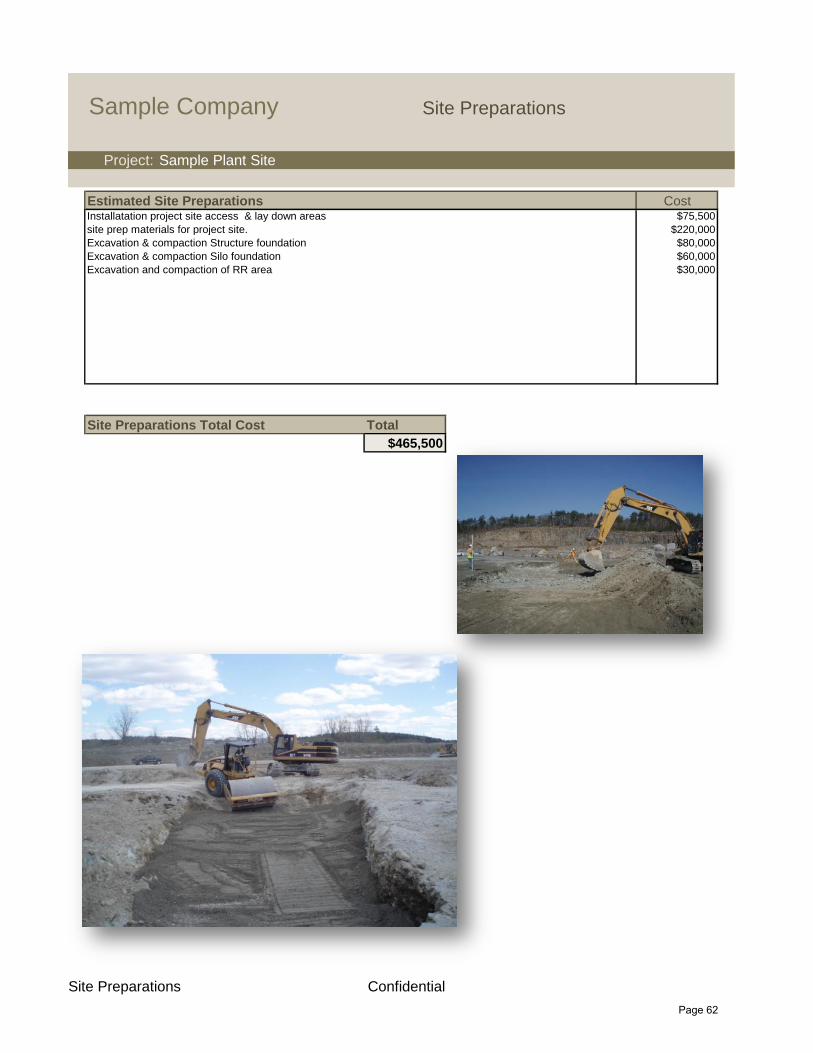
Sample Company Site Preparations
Project: Sample Plant Site
Estimated Site Preparations CostInstallatation project site access & lay down areas $75,500
site prep materials for project site. $220,000
Excavation & compaction Structure foundation $80,000
Excavation & compaction Silo foundation $60,000
Excavation and compaction of RR area $30,000
Site Preparations Total Cost Total
$465,500
Site Preparations Confidential
Page 62

Sample Company Freight Summary
Project: Sample Plant Site
Estimated Freight rates from Suppliers CostLippmann $8,200
American Bin & Conveyor $135,000
Tank Connection $85,000
McLanahan $14,500
Midwest Processing $25,000
Deister Machine $12,000
Tristate $4,200
REMco $6,500
Tarmac International $60,000
Miscellaneous $120,000
Structure Cost Total
$470,400
Freight Confidential
Page 63

Sample Company Electrical Summary
Project: Sample Plant Site
Plant Electrical Cost$2,169,500
Plant Electrical Total $2,169,500
Plant Automation Cost$1,156,000
Plant Automation Total $1,156,000
Total H.P. Total
4,308
Electrical Cost Total
$3,325,500
Open Architecture
Electrical Confidential
Page 64

Sample Company Preliminary Project Schedule
Project: Sample Plant Site
Task Days Start Date End Date
Total Project 240
Pre-engineering 20 3/1/2011 3/20/2011
Order Equipment 10 3/1/2011 3/25/2011
Detailed Engineering 60 3/1/2011 5/30/2011
Fabrication 120 3/1/2011 6/30/2011
Concrete Installation 60 3/1/2011 4/30/2011
Receive Equipment 60 4/1/2011 57/30/2011
Install Equipment 105 5/1/2011 10/5/2011
Electrical 60 8/1/2011 10/5/2011
Commission Plant 14 10/5/2011 10/30/2011
Project Management is absolutely critical to the success of any project. We provide experienced project managers who have
a proven track record of safely completing projects on time, and on budget.
All have over 20 years of experience
Define the complete scope of the project
Create realistic timelines and Gantt charts
Develop and execute a project plan
Determine the capabilities of all of the required resources
Directly manage all subcontractors
Track progress of all project activities
Develop and track budget versus actual costs
Clearly communicate with all stakeholders
Provide daily onsite support for the duration of the project
Provide leadership throughout the project
July Aug Sept OctMarch April May June
Schedule ConfidentialPage 65

Run: 1/13/11 22:08:46Calculation results may differ due to variations in operating conditions and application of crushing and screening equipment. This information does not constitute an express or implied warranty, but shows results of calculations based on information provided by customers or equipment manufacturers. Use this information for estimating purposes only.
All calculations performed by AggFlow. http://www.AggFlow.com
Sample CompanySample SiteWet Flow Sheet TPS T.ButlerDate: April/21/2011
121 stph 1F01
CR01
30x48
63 stph3 CSS
C01
11/2
5x12
SCR01
C03
C02
C04
1/4#8
8x20SCR02A C07
CR03BSandmax 800
0.0 stph
0-100 %SP01
1/4#8
8x20SCR02B
C05
0-100 %SP02
C06
C08
FMW01ATwin 44" x 33'
FMW01BTwin 44" x 33'
C10
CR03ASandmax 800
125 stph
C09
C11 50-50 %
SP03
C12
-8 mesh x +140 mesh
DECANTING PILE (SURGE TUNNEL)
WET PROCESSED SAND
WINTER STORGE PILE
-8 mesh x +140 mesh
C17C16 C15 C14 C13
WINTER STOREGE PILE RECLAIM
C13 C14 C15 C16
FH02
BF05
UFR01
UFR PRODUCT
C19
SBF01
TRASH/FROZEN CHUNKS/OVERSIZE
C20
1/2 4x12
SCR03
BF02BF03
C21
DRYER FEED
SEE DRY FLOW SHEET
-8 mesh x +140 mesh
Items in Blue notes phase II Equipment items
Items in gray notes muti-use equipment items
Orange Box notes UFR unit consiting of
3ea Cyclones1ea Feed distibutor1ea Dewatering Screen VD-121ea Collection Sump1ea Surry Pump
These items consist of four jumper conveyors.(C13 thru C16) these conveyors will be used tobuild the winter storage pile during the crushinseason. During the winter they will be used inconjunction with a portable feed hopper (FH01to reclaim the material and feed it back to the decanting pile for further processing.
C18
FH01
BF04
H 4800 S/F
CR02
Ponds
0.0 stph
W
Water suppliedby existing pump located in the river
W
Page 66

Run: 1/13/11 21:56:30Calculation results may differ due to variations in operating conditions and application of crushing and screening equipment. This information does not constitute an express or implied warranty, but shows results of calculations based on information provided by customers or equipment manufacturers. Use this information for estimating purposes only.
All calculations performed by AggFlow. http://www.AggFlow.com
Sample companySample SiteDry Flow Sheet TPS T.ButlerDate: April/21/2011
DRYER FEED
SEE WET FLOW SHEET
-8 mesh x +140 mesh
TRAIN CAR LOADING AREA
CERTIFIED BELT SCALE
DRYER
S
BURNER
FINES TANKFINE MATERIAL STORED IN THIS TANKTHEN BLOWN TO EXISTING FINE GRINDBUILDING USING EXISTING EQUIPMENT
200 TON
50-50 %SP04
SC01
SC02
S
FN01
C22
DUST COLLECTION
FUEL TANK
STACKBAG HOUSE
CYCLONEFEED HOPPER
FH03
+20CT04
50-50 %
#40#70
SC504B
#40#70
2ea ) 6022S2 SUPER-DECK SCREENS
PRIMARY SCREENS
SCR04A
#20#40
SUPER-DECK
POLISHING 1ea) 6033S1
SCREEN
SCREEN
SCR06
BF07 BF06
BE03BE01
20/40
CYCLE TANKS
CT0340/70
CT01CT02100M
#70
SECONDARY
1ea ) 6022S2
SUPER-DECK SCREEN
SCR05
+20+20 OVERSIZE TANK100 TONNE C24
EXISTING RE-BUILT VSI
CR04
C25
SP06
SP05
C27
S
FN02
STACK
C28
C30
100-0 %
SP07
ANY MATERIAL IN CYCLE TANKS CAN BE DISCHARGED HERE
OUTLET AREA40/70
1500 TONNE
100 MESH
1500 TONNE
C31
BATCH TANK
500 TONNE
CAN BE A BLEND OF ANY OF THE CYCLE TANKS
OR OVERSIZE SALES
TRUCK LOADING TRUCK SCALE
C33
Items in Magenta notes fines material
Items in Gray notes dust control pick up points
FINE GRIND FEED
C29
C23 C26
EXISTING MAGNET
BE02
SC03
SP08
Page 67

Page 68
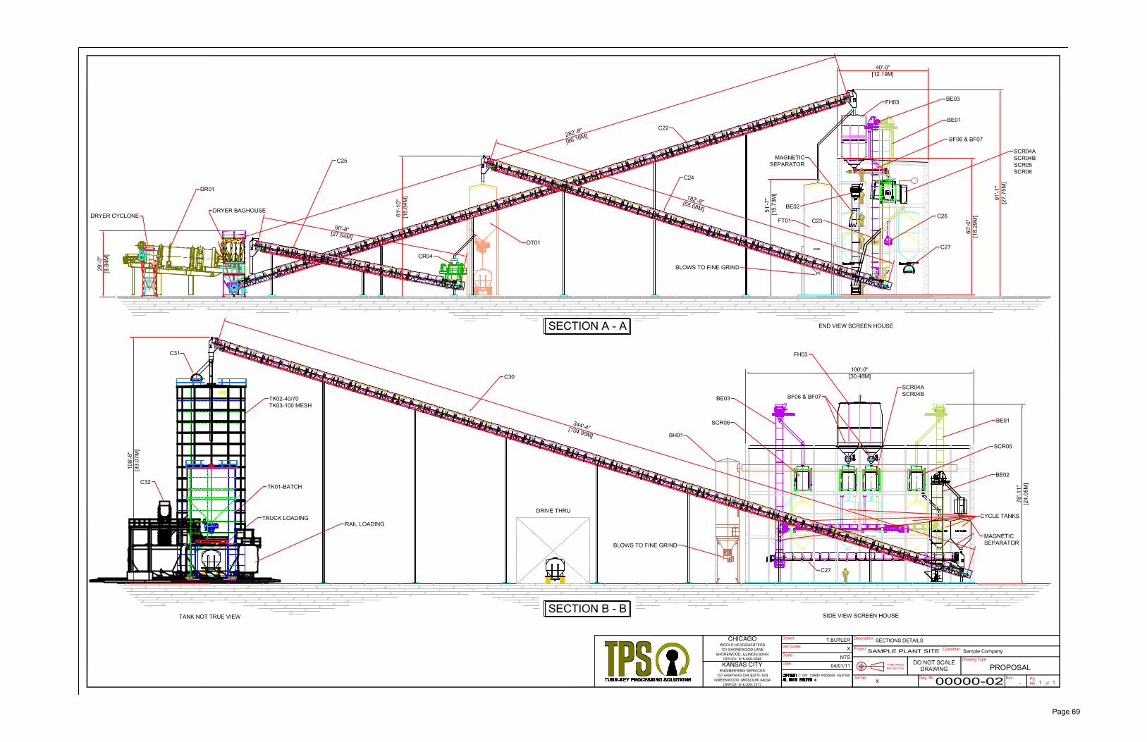
Page 69

Page 70