preparation time: safety notes: lesson … tie chord materials: ... on the end block and tie it to...
TRANSCRIPT

Activity Kit #3 Bridges
1
OBJECTIVES: To identify the different types of
bridges: arch, suspension, truss, beam, cantilever and cable stayed.
Learn the various loads which real life bridges are subjected to.
Understand how each bridge structure works to carry the loads placed on the bridge.
Discover how the different types of bridges fail and what modifications can be made to the bridge to increase its strength.
Appreciate the important aspects of construction such as strength and placement of materials.
Develop an understanding of the requirements of the materials used in bridge construction.
Relate the bridge models to real life situations.
SAFETY NOTES: Supervision is recommended as the activity:
Requires use of metal masses. Avoid over stacking of masses and keep a large clear area around the test in case they topple over.
Uses pins. Keep fingers and all other body parts clear of the sharp end of the pin. If you are finding it difficult to push the pins through use a hard surface to help you.
Uses stanley knives. Ensure students cut away from themselves and others when using the knives and ensure the blades are retracted when they are not in use or are being carried between groups.
Uses pliers. Ensure you keep fingers well clear from between the pliers.
Uses hot glue guns. The glue from the hot glue gun can cause burns if the glue contacts the skin both while expelling from the gun or before it has set. If you are burnt immediately run the affected area under water.
WORDS TO KNOW: Abutment Pier Span Arch Bridge Suspension Bridge Truss Bridge Cantilever Bridge Beam Bridge Cable Stayed Bridge
PREPARATION TIME:
LESSON TIME:
TESTING TIME:

Activity Kit #3 Bridges
2
Forces Loads Compression Tension Strut Tie Chord
MATERIALS:
1 QUT Bridge Activity Kit containing: Part One:
4 Instruction Booklets 4 Foundation Blocks 4 Individual Group Instruction Sheets 3 Stanley Knives 2 Balsa Cement 1 reel of Cotton Paddle Pop Sticks Hot Glue Gun Perspex Arch Strip of Paper Balsa Wood Sticks Sewing Pins Crimping Beads Tin Snips Flat Nosed Pliers Cardboard
Part Two:
Loading Trolley Masses Part 2 Bridge Pieces
STEPS:
PART ONE: 1. Explain the safety rules as
outlined in the safety notes above. 2. Divide the class into 4 groups and
allocate a bridge type to each group. (If there are odd numbers assign the smaller group to the beam bridge.)
3. Provide each group with the following materials:
Group 1 – Truss Bridge Balsa Wood Stanley Knife Pins Balsa Cement
Ruler Foundation Block Cardboard Truss bridge construction instructions
Group 2 – Arch Bridge Paddle pops Perspex Arch Strip of Paper Hot Glue Gun Cardboard Tin Snips Foundation Block Arch Bridge Construction instructions
Group 3 – Suspension Bridge
290mm piece Cardboard Balsa Wood Cotton Crimping Beads Balsa Cement Ruler Stanley Knife Flat nosed pliers Foundation block Suspension Bridge Construction
Instructions Group 4 – Beam Bridge
Balsa Wood Balsa Cement Ruler Foundation Block Beam Bridge Construction Instructions
4. Each group will now construct
their specified bridge as outlined in the instruction sheets which begin on the following page.
5. The bridges will be loaded to show the action of members and determine the strengths and weaknesses of each bridge type. This will be done using the truck and smaller weights supplied.
6. The second stage of testing will show the difference some small changes to the structure can make to the bridge performance.
7. The bridges will then be loaded to failure if possible.

Activity Kit #3 Bridges
3
1. Select the following pieces of
Balsa: 4 pieces 350 mm in length 12 pieces 130 mm in
length 7 pieces 100 mm in length 2 pieces 200 mm in length 4 pieces 10 mm in length
2. With the 350 mm pieces: Take 2 of them and using
your ruler and a pen put a mark at 10mm, 120mm, 230mm, 340mm. Then push a pin through the piece at each of these points – these will be the bottom chords.
Take the two remaining pieces and mark 65mm, 175mm, 285mm. Push a pin through the piece at each of these points – these will be the top chords.
3. Use a 130mm piece and put the
first pin on the bottom chord through the piece approximately 5mm from the end (so the balsa wood does not split). Then with the same piece, push the first pin
on the top chord through it at about 5mm from the piece’s end. Take another 130mm piece and repeat the process using the second pins, followed by the third pins, on both the top and bottom chords. Push a 10mm length onto the fourth pin on the bottom chord.
4. Next, take 3 more of the 130mm
pieces and push them onto the pins in same manner as before starting from the other end. Place a 10mm length over the final pin.
5. Repeat this for the other side of
the truss.

Activity Kit #3 Bridges
4
6. Now take the 100mm pieces,
push them onto the ends of the pins on one side of the truss so that they are perpendicular to it.
7. Then push the pins on the other truss through the other ends of the 100mm pieces. Your 2 trusses should now be joined together.
8. Place the cardboard deck through the middle of the bridge so that it is resting on the bottom chords.
9. With the 2 200mm lengths, cut the ends diagonally so that they will fit between the two top chords of the truss. Do not affix them to the bridge yet, this will be done in the second phase of testing.
10. Before testing your bridge, think about the following questions.
What type of bridge have you built?
What characteristics of the bridge identify it as that type?
How do you think the bridge will fail?
Name a famous bridge similar to the one you have just built; or one in your local area?

Activity Kit #3 Bridges
5
1. Set up the Hot Glue Gun and
allow to heat up. Remember that the glue coming out of the glue gun can burn your skin!
2. With the strip of white paper
place it over the perspex arch and secure so it can not move.
3. Starting from one side apply
glue to the paper and begin to place the paddle pop sticks on the glue.
4. Continue this until a layer of
paddle-pops covers the arch. 5. Then starting from the middle
on the top of the arch. Begin to place another layer of paddle-pops over the arch. It is important to ensure the
paddle-pops from the first layer over lap with the paddle-pops from the second layer.
6. Continue this until the arch is
covered with a second layer. 7. Repeat step 5 overlapping the
paddle-pops to produce layer 3.
8. Once the arch has been
covered with 3 layers of paddle-pops and the glue has dried (≈ 2-3 min) remove the perspex arch and the paddle-pop arch should now be free standing.

Activity Kit #3 Bridges
6
9. Place the paddle-pop arch
between the arch foundation block and place the cardboard on the supports.
10. When it is your turn to test the
bridge have a group member ready with the answers to the following questions:
What type of bridge have
you built?
What characteristics of the bridge identify it as that type?
How do you think the bridge will fail?
Name a famous bridge similar to the one you have just built; or one in your local area?

Activity Kit #3 Bridges
7
1. Take the 290mm piece of
cardboard and using your ruler, starting from the centreline of the piece mark 70 mm intervals on one side of the cardboard. Draw a line at each end of the interval across the width of the cardboard.
2. Take the five (5) balsa wood sticks 150mm in length and using Balsa Cement glue the five balsa sticks onto each of the drawn lines. Set aside and allow it to dry.
3. Using the cotton, cut: 2 pieces of cotton 1.5m in
length 10 pieces of cotton approx
30 cm in length 4. Onto one of the long strands,
thread 5 crimping beads. Find the centre of the strand and put it on the centreline of the marking sheet.
5. Move the Crimping Beads to the positions marked on the marking sheet.
6. Thread one 30cm piece of cotton through the crimping bead already in the position set out on the marking sheet in step 4. Using the Pliers, flatten the bead so that both the bead and both pieces of cotton will not move.
7. Repeat step 6 for the other crimping beads.
8. When the glue is dry on the cardboard deck position it so that one end is resting on a tower support and the other on the base of the testing frame.

Activity Kit #3 Bridges
8
9. Lay the long strands with the flattened crimping beads on them over the towers so that the central crimping beads are approximately halfway between the towers. Ensure the cotton is between the guide cuts on the top of the tower columns.
10. Tie the cotton off at either end by
placing the cotton in the notches on the end block and tie it to the nail on the inside of the end block. Ensure that you leave a little slack in the chord.
11. Starting at the one end of the deck tie each of the 30cm pieces of
cotton to the balsa sticks on the cardboard deck and try to get it level.
12. When it is your turn to test the bridge have a group member ready with the answers to the following questions
What type of bridge have you built?
What characteristics of the bridge identify it as that type?
How do you think the bridge will fail?
Name a famous bridge similar to the one you have just built; or one in your local area?

Activity Kit #3 Bridges
9
1. Take the following balsa wood:
8 pieces 350mm in length 2 pieces to the same
height as the recesses in the abutments (≈145mm)
2. Take two (2) of the 350 mm pieces and glue another 350 mm on top of each using the Balsa Cement.
3. Take one of the 350mm lengths that you have not glued. Using your ruler find the centre point of the piece. Push a pin through this point. Repeat this on another 350mm piece. Attach the 2 shorter pieces on the end of these pins as centre piers.
4. There will be three different bridges for you to observe in the
testing stage of this activity. These are:
Single depth beam Double depth beam Internal pier beam
5. When it is your turn to test the bridge, have a group member ready with the answers to the following questions.
What type of bridge have you built?
What characteristics of the bridge identify it as that type?
How do you think the bridge will fail?
Name a famous bridge similar to the one you have just built; or one in your local area?

Activity Kit #3 Bridges
10
PART TWO:
TESTING AND DISCUSSIONPRE-TESTING DISCUSSION
1. When the models have been built, discuss with the students:
The 4 types of bridges, the
components and forces.
Ask the students to predict the mode of failure and approximately at what load this will occur, if any. It should be noted that there is only 7.0kg available to load the bridge.
Seek justification for their
responses. TESTING Stage One: NOTE: DO NOT LOAD THE BRIDGES TO FAILURE IN STAGE ONE.
1. Load the bridges one at a time in the centre and if time permits numerous places along the deck including:
Quarter points Edge
2. Ask students to point out the
members under tension and compression.
3. Highlight the areas of the
bridge that are bending or twisting. Measure deflections to compare to other bridges and talk about serviceability.
4. Discuss with the students the following questions:
While the bridges are
being loaded watch all members and determine whether they are in tension or compression. Does this correlate with your pre-testing thoughts?
What force is acting on
the members that are twisting and bending? (Tension or Compression)
Why does loading the
bridges at different points produce different deflections?
After seeing the
deflections under light loads. How do you now think the bridge will fail?
5. Once you have demonstrated the mechanics of the bridge and shown the weaknesses of the structure STOP any further loading of the bridge.
Stage Two:
1. Add to the bridge any parts provided for the second stage of testing. These will be: Truss – Diagonal members on the top Beam – Middle pier
- Double depth beam Arch – Moving abutment. Arch Blocks

Activity Kit #3 Bridges
11
2. Discuss with the students how these modifications changed the way the bridge behaves?
3. Load the bridge to FAILURE if
possible. How much did the bridge hold and how did it fail?
NOTE: The arch bridge may not fail with the weight supplied. You are able to push down on the deck and it should then fail.
4. What force keeps the blocks in the block arch together?
DISCUSSION CHALLENGE: These questions are only a guide and should be modified to suit the level of understanding in the class.
Why did the bridge break at that particular spot?
How could the bridge be
improved?
Discuss the suitability of the bridge type to real life situations. What are the advantages and disadvantages of each of the bridge types?
What materials might you
use in a real life construction?
Other Questions are available on the Bridge Kit Information Sheet and you should think of others.

Activity Kit #3 Bridges
12
BACKGROUND INFORMATION: Bridges are structures, which carry people and vehicles across natural or man-made obstacles. A large part of everyday life, bridges have always represented a means of bringing together civilisations and providing the most fundamental modes of passage. Consequently they have become an important part of any transportation system. Early bridges were made from materials such as wood, stone and fibres. Today, most bridges have a concrete, steel, or wood framework with an asphalt or concrete roadway. Based on the length of the barrier to be crossed, the amount and type of traffic as well as forces of nature (wind, tide and flood), different materials and shapes of bridges are used. There are many types of bridges such as ARCH bridges, BEAM bridges, TRUSS bridges, SUSPENSION bridges, CANTILEVER bridges, and CABLE-STAYED bridges. A lot of bridges are actually combinations of different types of bridges and no two bridges are identical! Most bridges are held up by at least two supports set in the ground called ABUTMENTS. Some bridges have additional supports along the middle of the bridge called PIERS. A SPAN is the distance between two supports, two piers, a pier and an abutment or two abutments. Short bridges are often supported only by the abutments and are called single-span bridges. Longer bridges usually include one or more piers to
support them and are known as multi-span bridges.
HOW BRIDGES WORK:
Figure 1 – Tension and compression diagram.
“How Stuff works”, 8 January 2004. www.science.howstuffworks.com/bridge2.htm
Although there are many types of bridges most bridges work by balancing COMPRESSION and TENSION (Figure 1). Place a flexible object like an eraser, sponge, or small piece of bread between your thumb and index finger. Press your fingers together. One side of the object will bend inwards and shorten while the other will bend outwards and lengthen. The shorter side has been compressed, while the other side is under tension. Bridge components experience these tension and compression stresses. Most bridges use STRUTS and TIES in their structure. A strut is a member which is in compression and prevents two other structural members from pushing together. A tie is a member which is in tension and prevents two other structural members from pulling apart. Bridge materials, like stone, wood, steel and concrete, all have different strengths. For example, steel can be much stronger than wood. Each of these materials can withstand different amounts of compression and tension. For example, stone can withstand a lot of compression, but

Activity Kit #3 Bridges
13
under a lot of tension will break. Steel is very flexible and can endure a lot more compression and tension then materials like iron, wood or stone. Some materials are easier to mould into a particular shape than others. Engineers will select materials for a bridge design based on the strength of the material, the amount and type of stress a material can withstand, the required shape of the material and the availability of the material. They will also consider how easy the material is to work with. For example, stone is heavy to work with and cannot be moulded easily into a desired shape. When an engineer designs a bridge they carefully consider the different loads that the bridge will be subjected to in its lifetime. Not only does the bridge need to support its own weight (self-weight), it will need to carry the load of passengers and vehicles travelling across it. In addition the bridge design will need to consider the effects that wind and earthquake will have on the bridge. These factors are critical to the success of the bridge and ignoring one of them can lead to full bridge collapse! For example, Figure 2 and Figure 3 show pictures of the Tacoma Narrows Bridge which collapsed in 1940. This occurred during a violent windstorm which made the whole bridge twist. The engineers involved had not considered the wind effects, which moved the bridge in a wave motion.
Figure 2 - Tacoma Narrows Bridge. “How Stuff Works”, 8 January 2004. www.science.howstuffworks.com
Figure 3 - Tacoma Narrows Bridge. “How Stuff Works”, 8 January 2004. www.science.howstuffworks.com
YOUR MODEL IN REAL LIFE Models are commonly used in civil engineering to demonstrate real life applications of engineering concepts. Engineers develop relationships for their models in order to predict the outcomes of a real life structure. Scale is a ratio of size between a thing and a model or map of it. Scale can be used in this activity to get an understanding of the size that the bridge members might be in real life. In addition, using the scale principle, we can imagine the severity of the bridge movement in a real life application. Observe the amount of deflection the bridge is experiencing and scale that to a real life parameter.

Activity Kit #3 Bridges
14
DIFFERENT TYPES OF BRIDGES: Arch Bridge Suspension Bridge Truss Bridge Cantilever Bridge Cable-stayed Bridge Beam Bridge
ARCH BRIDGE The arch bridge is one of the oldest types of bridges. Early arch bridges were made from stone (Figure 4). The spans range up to about 300 metres.
Figure 4 -Ancient Roman aqueduct
National Information Service for Earthquake Engineering, University of California, Berkeley www.nisee.berkeley.edu
Arch bridges are semicircular in structure and are supported at the ends by abutments. The main forces within an arch bridge are compression forces. It is the natural curve of the arch shape which allows the weight of the bridge to be carried outward to the supports at each end. The supports or abutments in turn absorb the arch’s loads and prevent the arch from flattening out. Arch bridges differ in the steepness of their
slopes. Steeper arches can support larger loads as the abutments are more vertical and the compression force is being transferred in a straighter line than a flat shaped arch. Figure 5 shows the distribution of loads throughout an arch structure.
Figure 5 – Distribution of forces in an arch bridge.
Now, arches are rarely built from stone. Modern arches are built from steel and similar materials which are easier to mould into desired shapes and are lighter in weight, making the bridge easier and faster to construct.
SUSPENSION BRIDGE A suspension bridge has at least two main cables. These cables extend from one end of the bridge to the other. The cables must be secured and anchored past the ends of the bridge. Suspender cables hang from these main cables. The other end of the suspender attaches to the roadway. Perhaps one of the most famous of all suspension bridges is The Golden Gate Bridge in San Francisco, California (Figure 6).

Activity Kit #3 Bridges
15
Figure 6 - Golden Gate Bridge Suspension bridges have the longest spans in the world and are used to cross great distances. These types of bridges are used to cross deep-water channels, cannons or gorges, where construction of supporting piers can be difficult. The towers can be placed far apart eliminating the need for multiple towers and piers.
Suspension bridges have the ability to span great distances – far longer than any other style of bridge. The Akashi Kaikyo Bridge (Figure 7.) is currently the largest suspension bridge in the world and crosses a distance of 3910m that is almost 4km! The distribution of forces within a suspension bridge is shown in Figure 8.
Figure 8 – Distribution of forces in a Suspension bridge.
“How Stuff Works”, 8 January 2004. www.science.howstuffworks.com/bridge4.htm
Figure 7 – Akashi Kaikyo Bridge
“View of Akashi Kaikyo Bridge in day”, By Courtesy of the Honshu-Shikoku Bridge Authority.
Activity Kit #3 Bridges
16
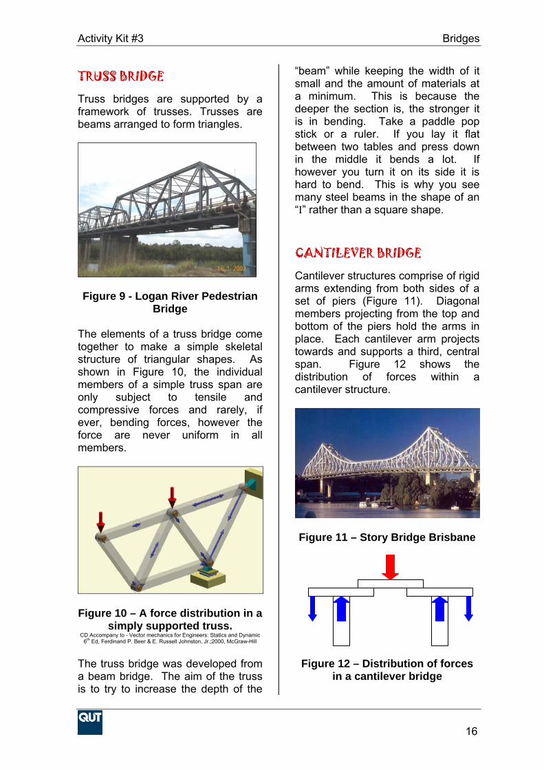
TRUSS BRIDGE Truss bridges are supported by a framework of trusses. Trusses are beams arranged to form triangles.
Figure 9 - Logan River Pedestrian Bridge
The elements of a truss bridge come together to make a simple skeletal structure of triangular shapes. As shown in Figure 10, the individual members of a simple truss span are only subject to tensile and compressive forces and rarely, if ever, bending forces, however the force are never uniform in all members.
Figure 10 – A force distribution in a
simply supported truss. CD Accompany to - Vector mechanics for Engineers: Statics and Dynamic
6th Ed, Ferdinand P. Beer & E. Russell Johnston, Jr.;2000, McGraw-Hill
The truss bridge was developed from a beam bridge. The aim of the truss is to try to increase the depth of the
“beam” while keeping the width of it small and the amount of materials at a minimum. This is because the deeper the section is, the stronger it is in bending. Take a paddle pop stick or a ruler. If you lay it flat between two tables and press down in the middle it bends a lot. If however you turn it on its side it is hard to bend. This is why you see many steel beams in the shape of an “I” rather than a square shape.
CANTILEVER BRIDGE Cantilever structures comprise of rigid arms extending from both sides of a set of piers (Figure 11). Diagonal members projecting from the top and bottom of the piers hold the arms in place. Each cantilever arm projects towards and supports a third, central span. Figure 12 shows the distribution of forces within a cantilever structure.
Figure 11 – Story Bridge Brisbane
Figure 12 – Distribution of forces
in a cantilever bridge

Activity Kit #3 Bridges
17
CABLE-STAYED BRIDGE Cable-stayed bridges have roadways that hang from cables. The cables are connected directly to towers (Figure 13).
Figure 13 - A cable-stayed bridge
near Savannah, Georgia, USA. “How Stuff Works”, 8 January 2004.
www.science.howstuffworks.com/bridge4.htm
It is another example of suspension style of bridge with its definitive “A” shape. However, unlike its counterpart, the cable-stayed design instead runs its cables directly from the roadway up to a single tower where they are secured. Although they may appear similar in form each bridge supports the load of the roadway in very different ways. The difference lies in how the cables are connected to the towers. Tower elements in cable-stayed structures do not transfer forces to awaiting anchorage houses but instead absorb and disperse all compressive forces alone. Cable-stayed bridges also offer greater stiffness, torsional and lateral rigidity over that of suspension bridge. Figure 14 shows the distribution of forces throughout a typical cable-stayed structure.
Figure 14 – Distribution of forces in a cable-stayed bridge
“How Stuff Works”, 8 January 2004. www.science.howstuffworks.com/bridge4.htm
BEAM BRIDGE Beam bridges while not normally aesthetically pleasing are the simplest and most cost effective to construct. Beam bridges are often modular in design and consist of simple beam – column design. The best example of a beam bridge is a log across a gully. The beam is simply supported between the abutments/columns in either a single or continuous span. Figure 15 shows a simply supported beam bridge with 3 single spans.
Figure 15 – A 3 span beam bridge A load applied to the bridge is transfer through the beam and then

Activity Kit #3 Bridges
18
resisted by the abutments and columns as seen in detail in Figure 16 Figure 16 – Force distribution in a
beam bridge A beam bridge can be found on many rural and outer urban roads where aesthetics is not a high priority. A beam bridge is by far the most common type of bridge structure used. GLOSSARY: Arch – A curved structure that converts vertical force into angled forces that travel down through its sides to a foundation. Bending - A combination of forces that causes one part of a material to be in compression and another part in tension. Cantilever - A structure that projects beyond its point of support. Compression - A pressing force that squeezes material together. Concrete - A building material made by mixing stone or sand with cement and water. Concrete is very strong in compression but very weak in tension. Force - A push or pull on an object. Formwork - The temporary mould into which liquid concrete is poured to create a specific shape. Girder - A large beam, often built up from smaller pieces. Girders usually support smaller beams.
Keystone - The central, wedge-shaped locking stone at the top of an arch. Pier - A vertical support such as a column. Reinforced concrete – Concrete with steel bars embedded in it to improve resistance to tension. Steel - An alloy of iron and carbon that is hard and strong and can be pounded or rolled into desired shape. Tension - A stretching force that pulls on a material Truss - A rigid frame built up from short straight pieces that are joined to form a series of triangles or other stable shapes. REFERENCES: How Stuff Works (2004) “Bridge”, URL: http://science.howstuffworks.com/bridge4.htm (08/01/04)
National Information Service for Earthquake Engineering (1998) “William G. Godden Structural Engineering Slide Library” URL: http://nisee.berkeley.edu/godden/godden_intro.html (27/01/04)
The Honshu-Shikoku Bridge Authority (2004) “Photo Gallery”. URL: http://www.hsba.go.jp/photo/index.htm. (27/01/04)
The Bridge Site (2000) “Fun and Learning About Bridges” URL: http://www.bridgesite.com/funand.htm (20/08/01)
Super Bridge (1998)”Nova Online” URL: http://www.pbs.org/wgbh/nova/bridge/ (22/08/01)
ACKNOWLEDGMENT Created by Emma Carden in the School of Civil Engineering, 2003
Abutment Abutment

Activity Kit #3 Bridges
19