preparation of cast iron foundry alloysnodular iron the addition of magnesium (‘inoculation’)...
TRANSCRIPT
Solutions for Materials Preparation, Testing and Analysis
By: Janina Radzikowska & George Vander Voort
Preparation of Cast Iron Foundry Alloys
Published by Buehler, a division of Illinois Tool Works Volume 3, Issue 2
Metallography in PolandEditor’s Note: We are extremely pleased to be able to present to you in this issue the superb work of Mrs. Janina Radzikowska, senior metallographer at the Foundry Research Institute in Kraków, Poland. The very high quality of her work should be an inspiration to metallographers everywhere.
Cast irons can exhibit a wide range of microstructural constituents depending upon their composition and heat treatment. Their preparation is difficult due to the need to properly retain the graphite phase when it is present. The presence of microshrinkage cavities also presents problems, particularly controlling bleedout of fluids and etchants. Metallographic examination may involve only qualitative assessments, for example, to define the type and relative size of the graphite phase and identify phases and other constituents such as nitrides and inclusions. There has been a trend in the foundry industry to become more quantitative with image analysis measurements of the amounts of phases, graphite shapes, and nodule density. In our research work, we quantify structures fully. However, most foundries do not need to be as rigorous in quality control studies.
Preparation ProceduresFor our work, which often involves quantitative measurements using image analysis, we must faithfully reveal the true structure. Thus, our preparation procedure is more elaborate than that used by many foundries. We utilize color tint-etching methods extensively, and these require a very highquality preparation practice.
For the work shown here, I used the following procedure with slight modifications depending upon whether or not the specimen was to be etched and if a tint etch was to be used. Mounted specimens were placed in a holder for six (usually) specimens. Central force and complementary rotation (platen and holder rotating in same direction) were used. The steps were:1. 120 grit SiC paper, 300 rpm, 100N (22.5lbs.) force until all
surfaces are coplanar2. 240 grit SiC paper, 300 rpm, 100N force for 2 minutes 3. 9μm METADI® Diamond Paste on an ULTRA-PAD™ Cloth, 150
rpm, 100N force for 3 minutes4. 3μm METADI Diamond Paste on a TEXMET® 1000 pad, 150
rpm, 120N (27lbs) force, for 3 minutes5. 1μm METADI Diamond Paste on a TEXMET® 1000 pad, 150
rpm, 100N force, for 2 minutes6. Specimens etched lightly with 4% HNO3 in alcohol (nital)
7. MASTERPREP™ Alumina Polishing Suspension used on a MICROCLOTH® Polishing Cloth wet with water, 150 rpm, 90-120N (20-27 lbs) force (depending on degree of etch), for 1.5-2 minutes (depending on degree of etch)
METADI Fluid was used as the lubricant/ extender with the diamond abrasives. After each polishing step (Nos. 3, 4, 5 and 7), the specimens were washed with alcohol and blown dry with compressed air (which must be clean and dry). Washing with watersometimes results in corrosion stains on the surface, so I usually use only alcohol for the final cleaning step (No. 7). Individual forcecan also be used, especially if I do not have enough specimens to fill the holder (divide the force values given above by 6 to determine the individual force to use).
MicrostructuresOne should always begin microstructural investigations by examining the as-polished specimen before etching. This is a necessity, of course, for cast iron specimens if we are to properly examine the graphite phase. Brightfield vertical illumination will be our starting point, but the benefits of crossed polarized light will also be explored.
Janina Radzikowska, senior metallographer at the Foundry Research Institute in Kraków, Poland.
Visit our website at www.buehler.com for more information.
Cast irons with a composition equivalent to about 4.3% C solidify as a eutectic. Because cast irons are not simple binary Fe-C alloys, it is usual practice to calculate the carbon equivalent (CE) value which is the total carbon content plus one-third the sum of the silicon and phosphorus contents. If the CE is >4.3, it is hypereutectic; if it is <4.3, it is hypoeutectic. Table 1 lists the CE values and compositions for each cast iron shown in this issue.
In the Fe-C system, the carbon may exist as either cementite, Fe3C, or as graphite. So the eutectic reaction is either liquid transforming to austenite and cementite at about 1130°C or liquid transforming to austenite and graphite at about 1135°C. Addition of elements such as silicon promote graphite formation. Slow cooling rates promote graphite formation, while higher rates promote cementite. The eutectic grows in a cellular manner with the cell size varyingwith cooling rate which influences mechanical properties.
Gray IronFigure 1 shows interdendritic flake graphite in a hypoeutectic alloy (see Table 1 for composition of alloys) where proeutectic austenite forms before the eutectic reaction. This type of graphite has been given many names. In the US it is referred to as Type D (ASTM A247) or as undercooled graphite. It was thought that the fine size of the graphite might be useful, but it is not technically useful as it always freezes last into a weak interdendritic network.
Figure 2 shows more regularly-shaped graphite flakes in an alloy (Table 1) of higher carbon content, although still hypoeutectic. While flake lengths in Figure 1 are roughly 15-30μm, flake lengths in Figure 2 are in the 60-120μm range. Figure 3 shows somewhat coarser flakes (250- 500μm length range) in a higher carbon content cast iron (Table 1).
Other graphite forms are also observed. For example, Figure 4 shows disheveled graphite flakes in a casting. Note that a few nodules are present. This appears to be a mix of B- and D-type flakes. Figure 5 shows a hypereutectic gray iron where very coarse flakes form before the eutectic which is very fine. This is similar to C-type graphite.
Nodular IronThe addition of magnesium (‘inoculation’) desulfurizes the iron and causes the graphite to grow as nodules rather than flakes. Moreover,
mechanical properties are greatly improved over gray iron; hence, nodular iron is widely known as ‘ductile iron’.
Nodule size and shape perfection can vary depending upon composition and cooling rate. Figure 6 shows fine nodules, about 15-30μm in diameter, while Figure 7 shows coarser nodules (about 30-60μm diameter) in two ductile iron casts (see Table 1 for compositions). Note that the number of nodules per unit area is much different, about 350 per mm2 vs.125 per mm2, respectively.
Compacted GraphiteCompacted graphite is a more recent development made in an effort to improve the mechanical properties of flake gray iron. Figure 8 shows an example where the longest flakes are in the 60-120μm length range. Compare these flakes to those shown in Figures 2 and 3.
Crossed-Polarized LightExamination of graphite in crossed polarized light requires a very well-prepared specimen; otherwise, the matrix phase exhibits a heavy scratch pattern, and the graphite growth pattern will not be visible. Minor scratches can be tolerated in routine work.
The polarizer and analyzer filters are placed in the crossed position (i.e., 90° to each other which produces the darkest matrix appearance), and a sensitive tint plate (lambda plate) may be inserted to further enhance coloration. The lambda plate may be adjustable on some microscopes which changes the color pattern, as illustrated in Figures 9a and b. Personally, I prefer to set the background color tomagenta, as in Figure 9b. Working at a very high magnification, Figure 9c, provides more structural detail than at low magnification, Figure 9d, but requires high quality, stress-free objectives. Note the classic cross pattern seen at low magnification, Figure 9d.
Flake graphite can also be studied using polarized light, such as illustrated in Figure 10. The color varies with the crystallographic orientation of the graphite, and some internal details of the flake structure are better revealed in color.
EtchingTo see details of the matrix microstructure, specimens must be etched. The Polish standard for cast irons (PN-61/H-0503)
2
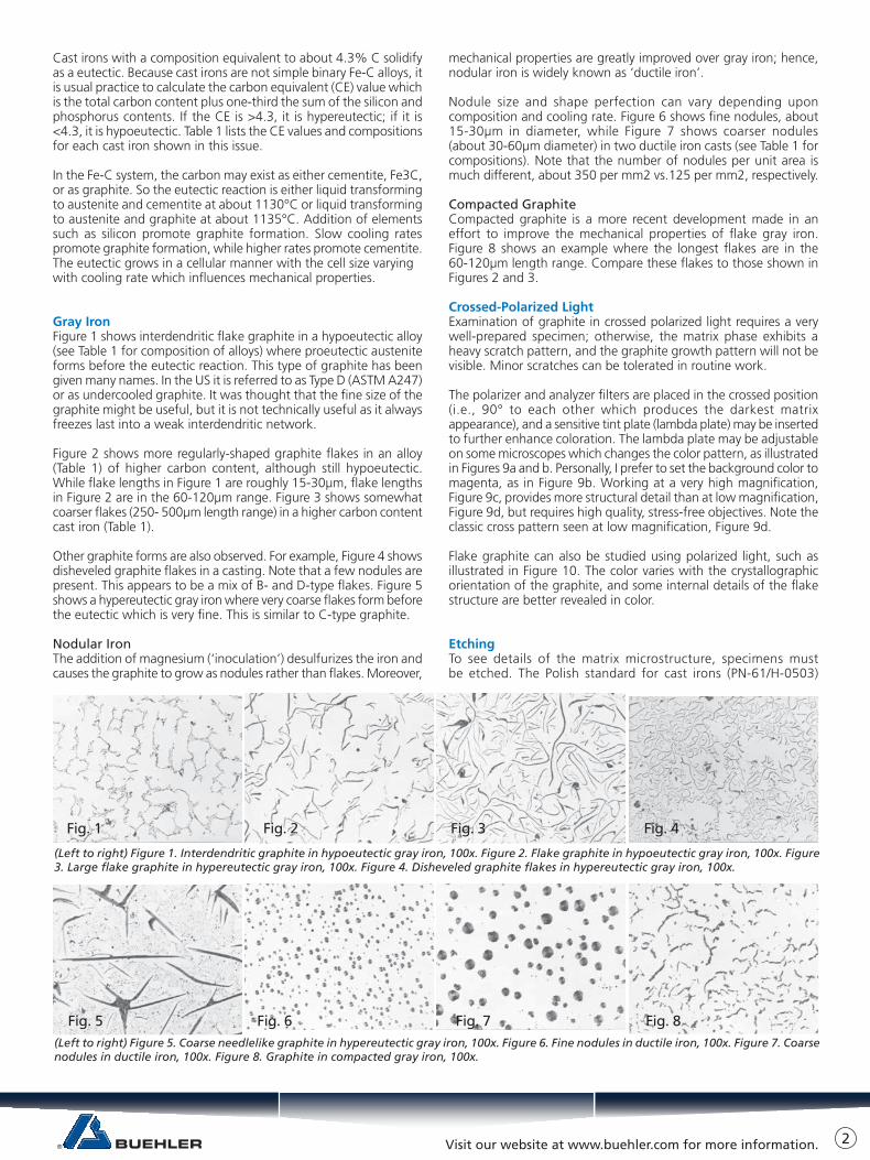
(Left to right) Figure 1. Interdendritic graphite in hypoeutectic gray iron, 100x. Figure 2. Flake graphite in hypoeutectic gray iron, 100x. Figure 3. Large flake graphite in hypereutectic gray iron, 100x. Figure 4. Disheveled graphite flakes in hypereutectic gray iron, 100x.
Fig. 1 Fig. 2 Fig. 3 Fig. 4
(Left to right) Figure 5. Coarse needlelike graphite in hypereutectic gray iron, 100x. Figure 6. Fine nodules in ductile iron, 100x. Figure 7. Coarse nodules in ductile iron, 100x. Figure 8. Graphite in compacted gray iron, 100x.
Fig. 5 Fig. 6 Fig. 7 Fig. 8

Visit our website at www.buehler.com for more information.
recommends three etchants. The first is 4% alcoholic nitric acid (“nital”) used at room temperature to reveal the ferrite grain boundaries and reveal phases and constituents such as cementite and pearlite. The second is alkaline sodium picrate (25g NaOH, 2g picric acid and 75 mL distilled water) used at 60 to 100°C for up to 30 minutes (1-3 minutes is usually adequate). This is used to color cementite yellow to brown (ferrite is not colored). The third is the standard version of Murakami’s reagent (10g KOH, 10g potassiumferricyanide and 100 mL distilled water) used at 50°C for 3 minutes to color iron phosphide dark yellow or brown (cementite and ferrite not colored).
Gray IronAs an example, Figure 11 shows a flake graphite specimen (see Table 1) etched with 4% nital. The matrix is predominantly pearlitic (colored tan, blue, and brown) and shows patches (arrow) of the ternary eutectic (ferrite, cementite, and phosphide). In comparison, Figure 12 shows the matrix structure of the specimen shown in Figure 2. The ternary phosphide is not present. The matrix is all fine pearlite.
Besides the ternary ferrite-cementite-iron phosphide eutectic and the previously mentioned binary eutectics (austentie and cementite and austenite and graphite), it is possible to obtain a binary ferrite-iron phosphide eutectic in cast iron. Figure 13 shows the binary ferrite-iron phosphide psuedoeutectic in the specimen previously shown in Figure 10, after etching with hot Murakami’s reagent which colors the phosphide brown but does not color ferrite.
Nodular IronDuctile iron specimens can have a wide range of matrix structuresdepending upon composition and as-cast cooling rate. Figure 14 shows a fully ferritic matrix after etching with 4% nital. Figure 15 shows a specimen with a pearlitic matrix and ferrite surrounding the nodules, while Figure 16 shows an example where a very small amount of ferrite remains around each nodule.
White Cast IronThe microstructure of white cast iron is best observed after etching. Figure 17 shows a typical example after etching with 4% nital. Note the interdendritic cementite (white) which ometimes has a Widmanstätten (‘spiky’) appearance. Austenite formed as the proeutectic constituent before the eutectic reaction (liquid transforms to austenite and cementite) and later transforms to pearlite and cementite upon cooling below the eutectoid temperature, about 723°C.
3
9a 9b
Figure 9. Polarized light examination of nodule substructure in ductile iron: a) sensitive tint plate adjusted to produce a blue background, 500x; b) sensitive tint plate adjusted to produce a magenta background, 500x; c) a higher magnification view, 800x; and, d) a lower magnification view, 250x.
9c 9d
Table 1. Composition of Cast Irons (Wt. %, Balance Fe)
Figure No. C Si Mn P S Ni Mg Cu Other CE
1 2.1 2.8 0.38 0.06 0.03 3.05
2, 12 2.8 1.85 1.05 0.04 0.025 3.43
3 3.5 2.95 0.04 0.08 0.02 0.13 0.15 4.51
4 3.5 2.7 0.55 0.13 0.02 0.03 0.46 Al 4.44
5 4.3 1.5 0.5 0.12 0.08 4.84
6 3.45 2.55 0.30 0.04 0.01 0.80 0.07 0.55 4.31
7 3.6 2.9 0.14 0.04 0.02 0.16 0.06 4.58
8 3.7 2.3 0.21 0.03 0.01 0.82 0.02 4.48
9 3.6 2.9 0.14 0.04 0.02 0.16 0.06 4.58
10, 13 3.3 1.64 0.31 1.42 0.11 4.32
11 3.3 1.9 0.3 0.49 0.04 1.2 4.10
14 3.7 1.25 0.03 0.02 0.02 0.24 0.06 4.12
15 3.7 1.25 0.2 0.02 0.02 0.22 0.06 4.12
16 2.8 2.8 0.2 0.045 0.02 0.88 0.06 0.48 3.75
17, 18 3.0 2.7 0.45 0.07 0.025 Te to mold 3.92
Figure 10. (Top) Flake graphite examined with crossed polarized light plus a sensitive tint plate, 200x. Figure 11. (Bottom) Microstructure of gray iron containing a pearlitic matrix and the ternary eutectic (4% nital, 250x). The larger white particles (arrow-c) are cementite while the adjacent area (arrow - fp) contains ferrite and iron phosphide.
Fig. 10
Fig. 11cÚ
fpÚ

Visit our website at www.buehler.com for more information. 4
Figure 18a shows a higher magnification view of this specimen etched with 4% nital. The massive cementite particles are clearly visible appearing to be outlined by the etch. Actually, the cementite is not attacked by the etch, while the surrounding structure is. The ‘outline’ around the cementite particles is due to light being scattered from the height difference or ‘step’ around the particles. Note that ferrite surrounds each cementite particle due to local decarburization. The pearlite is colored. Figure 18b shows the effect of etching this specimen with alkaline sodium picrate which colors the massive cementite brown. The cementite in the pearlite constituent is colored tan and blue. Ferrite is not colored.
ConclusionsModern polishing materials and procedures can be employed very effectively to reveal the microstructure of cast iron specimens. Graphite retention, always a problem with these metals, can be accomplished with a minimum of difficulty. Crossed polarized light is very useful for observing graphite substructure. Etching brings out the matrix constituents.
Selective etching with color producing films, briefly discussed here, is a highly informative tool. This will be discussed in more detail in a future issue.
AcknowledgmentsSpecimens for Figures 3, 16, 17, and 18 were provided by St. Fuksa and W. Wierzchowski, Foundry Research Institute, Kraków, Poland.
Tech-TipsQuestion: If I prefer to use the usual sequence of SiC papers to grind my gray iron specimens, what should I do to retain the graphite?
Answer: The usual sequence of 120, 240, 320, 400, and 600 grit SiC papers has been used for many years to grind gray iron specimens. However, if water is used with each paper, the graphite will be eroded away. Some people prefer to use a second sheet of 600 grit paper without any water. Others prefer to use water with the 120,240, and 320 grit papers and then grind dry with the 400 and 600 grit sheets. There is a risk of introducing thermal damage to the specimen in this way. Use of the contemporary practice describedin the text avoids this risk while preserving the graphite.
Question: I have problems with staining in both polishing and etching cast iron specimens. What can I do to prevent this problem?
Answer: Cast irons may experience staining problems, particularly if you have “hard” water. I would first try washing with distilled water followed by alcohol (ethanol) before drying. Hot water may lead to more staining problems than lukewarm water. Scrubbing the specimen with a detergent solution and cotton after polishing followed by rinsing with distilled water, then alcohol, followed by warm air drying may solve your problem. If this doesn’t work, you must avoid water in the final cleaning steps. One can use alcohol,kerosene, or mineral spirits. To avoid staining after etching with nital, avoid water -- use only alcohol. I have had staining and pitting problems using boiling alkaline sodium picrate. The only way I could prevent this problem was to add EDTA (ethylene-diaminetetra-acetic acid) to the etchant (about 2g per 100 mL). Sometimes it is possible to remove stains by ultrasonically cleaning the specimen in a 2-3%
Figure 12. (Top) Pearlitic matrix of the gray iron specimen shown in Fig. 2 etched with 4% nital, 100x. Figure 13. (Bottom) Gray iron specimen containing a binary ferrite-iron phosphide eutectic with the phosphide colored by the hot Murakami’s etch, 100x.
Fig. 12
Fig. 13
Figure 14. (Top) Fully ferritic matrix (note ferrite grain boundaries) of a ductile iron specimen etched with 4% nital, 100x. Figure 15. (Middle) Ductile iron specimen with substantial amounts of ferrite and pearlite etched with 4% nital, 100x. Figure 16. (Bottom) Ductile iron specimen with a pearlitic matrix and a small amount of ferrite surrounding the nodules etched with 4% nital, 100x.
Fig. 14
Fig. 16
Fig. 15
Figure 17. (Top) Microstructure of white cast iron containing massive cementite (white) and pearlite etched with 4% nital, 100x. Figure 18. (Middle and Bottom) High magnification views (400x) of the white cast iron specimen shown in Figure 17: a) etched with 4% nital; and, b) etched with alkaline sodium picrate.
Fig. 17
Fig. 18b
Fig. 18a

BUEHLER Worldwide Headquarters41 Waukegan RoadLake Bluff, Illinois 60044-1699 USAP: (847) 295-6500www.buehler.com | [email protected]
BUEHLER [email protected]
BUEHLER [email protected]
BUEHLER United [email protected]
BUEHLER [email protected]
BUEHLER [email protected]
BUEHLER [email protected]
BUEHLER [email protected]
Connect with us:
© 2015 BUEHLER, a division of Illinois Tool Works Inc. Printed in U.S.A. FN01051_0615
aqueous EDTA solution.
Question: I use silicon carbide papers going through the usual sequence to manually grind gray iron specimens before polishing. However, I have problems retaining the graphite. Can you suggest what I might be doing wrong?
Answer: Silicon carbide paper starts out cutting effectively but quickly wears out. After about one minute of grinding four to six specimens, it’s effectiveness is greatly reduced. The cutting rate drops to next to nothing, and frictional heat increases. If you are trying to get more life out of your papers than they are good for, your graphite will be ripped out of the surface. This could be your problem. Examine the specimens as you go through the grinding and polishing sequences to see where the problem begins. The fine gritpapers have lower cutting rates and wear out more easily. This is especially true for 600 grit (and finer) paper.
Of course, it is possible to pull out the graphite during the polishing phase as well. Again, only by examining the specimens after each step can you pinpoint the source of the problem. Low nap or napless cloths are safer for retaining the graphite. Lubrication is important. Too much drag is not helpful.
Question: When I etch my cast iron specimens, the ferrite is scratchy in appearance. How can I avoid this problem or cure it? Answer: The ferrite may be scratchy because you have shortcut the preparation sequence. Preparation is a series of steps each one building upon the previous. The first step must remove damage from cutting. If you use a band saw or power hacksaw, the depth of damage will begreater than if you use an abrasive cutoff saw. The first step must remove all of this damage. The coarser grits have the best metal removal rates. But each step does produce damage as well. So each step must remove all of the damage from the previous step. Polishing removes very little material. If the scratches you see are from a fine abrasive step, then you can remove it with a fine diamond abrasive or perhaps with an alumina slurry. But if the damage is deep, youmust go back to a coarser abrasive. Many metallographers like to use one or more etch-polish-etch cycles at the end of the preparationsequence. While this is good for removing minor amounts of smeared metal and finescratches, it does promote relief and edge rounding. Consequently, I do not recommend use of more than one such cycle.