preparation and characterisation of mnco2o4 and raney
TRANSCRIPT

Preparation and characterisation of
MnCo2O4 and Raney nickel catalysts
for alkaline fuel cells
Terhi Nissinen
University of Helsinki
Faculty of Science Department of Chemistry
Laboratory of Inorganic Chemistry Helsinki, Finland
Academic Dissertation
To be presented, with the permission of the Faculty of Science of the University of Helsinki, for public criticism in room 6, Fabianinkatu 33,
on October 22nd, 2004, at 12 o’clock.
HELSINKI 2004

ISBN 952-91-7724-0 (paperback) ISBN 952-10-2047-4 (PDF)
http://ethesis.helsinki.fi
Helsinki 2004 Yliopistopaino

iii
ABSTRACT
This thesis describes the preparation and characterisation of two catalysts, MnCo2O4 and Raney nickel, both of which can be used as catalysts in a number of different reac-tions. The activities of the catalysts were examined in electrode reactions in an alkaline fuel cell (AFC).
Decomposition of mixed Mn-Co nitrates and the formation of spinel MnCo2O4 were studied by thermogravimetry and by heat treatments in a furnace. The nitrates were heated in pure form or supported on carbon powder. The supported nitrates decomposed at lower temperature than the pure nitrates and produced less non-stoichiometric spinel with smaller crystallite size. Both the nitrates and spinel enhanced the oxidation of car-bon. A microwave-assisted route synthesis (MARS) was developed for the preparation of MnCo2O4. Under the conditions employed preparation by MARS was possible only when carbon (minimum 13 wt.%) was present as a microwave susceptor. The nitrates supported on carbon were heated in cycles of a few minutes with cooling in between. This procedure ensured the sufficiently slow oxidation of carbon and formation of spinel, unlike continuous microwave heating, which led to vigorous carbon burn-off and the formation of undesired phases. The microwave treatment to produce spinel could be shortened to one minute if most of the nitrates had first been decomposed at 200 °C in a furnace. Spinel-carbon catalysts prepared by the optimised MARS contained ~10 wt.% carbon and had combined surface area of 100 m2/g and small spinel particle size (<30 nm). The combined surface areas of the spinel-carbon powders increased with the carbon content. The catalytic activity towards oxygen reduction reaction improved as the amount of carbon in the powders increased up to ~10 wt.%. Increase in the carbon content beyond this value did not improve the catalytic activity for oxygen reduction reaction.
Metal dopants improved the catalytic activity of the Raney nickel catalysts for hydrogen oxidation reaction in the order Fe<Cu<Ti<La<Cr. Doping with Cr and Ti gave the best long-term stability. During the electrochemical experiment the surface concentration of Cr increased through formation of chromium oxide on the electrode surfaces. The Ra-ney nickel catalysts displayed typical surface areas of 50–80 m2/g. However, high con-tents of aluminium and oxygen in the samples indicated that the preparation process was not optimal. The catalytic activity could be improved through optimisation of the preparation process.

iv
PREFACE
This work was carried out during the years 2000–2004. The experimental work for pa-pers I and IV was done at the Laboratory of Materials Processing and Powder Metal-lurgy, Helsinki University of Technology (HUT), and that for papers II, III, and V at the Division of Chemical Reaction Engineering, the Royal Institute of Technology (KTH), Stockholm. XRD and IR analyses were done at the Laboratory of Inorganic Chemistry, University of Helsinki (HY). Funding from the Nordic Energy Research Program, For-tum Foundation, Wihuri Foundation, and the University is gratefully acknowledged.
Most sincere thanks are owed to many. My special thanks to my supervisors, who have supported and advised me throughout the work: to Professor Michael Gasik, who sug-gested the microwave-assisted preparation of the catalysts, to Professor Markku Lampinen, who aroused my interest in fuel cells, to Associate Professor Yohannes Kiros, who guided me and worked with me at KTH, and to Professor Markku Leskelä for his valuable comments and advice and for being the official supervisor of my studies.
Anneli Oksanen, Jaakko Lamminen, and Tuula Noponen guided me in the world of fuel cells and catalysts, and Pertti Kauranen first encouraged me to embark with postgradu-ate studies and helped me to obtain my first scholarship. Taina Valo, Jorma Laine, and Juha Linnekoski at HUT and Mehdi Majari at KTH performed a vital role as my closest co-workers. Ilkka Pitkänen at the University of Jyväskylä performed the TG-FTIR measurements and Michael Friman at HUT made the thermogravimetric measurements. Massoud Pirjamali, Marcelo Zuleta, and Martin Bursell assisted me with the electro-chemical measurements at KTH, and colleagues at the Laboratory of Inorganic Chemis-try assisted me with the XRD and IR measurements. My special thanks to them, and indeed to all members of our research team and to my many colleagues at HUT, HY, and KTH.
Needless to mention, I am most grateful to my friends in Finland and Stockholm for the great moments we have shared during the years. And finally, but not least, I thank Tommi and his family and my parents Rauha and Raimo, as well as Katja, Artsi, and Arto for their encouragement and support.
Helsinki, September 2004 Terhi Nissinen

v
LIST OF PUBLICATIONS
This work is based on the following original articles, which are referred to in the text by their Roman numerals.
I. T. Nissinen, T. Valo, M. Gasik, J. Rantanen, M. Lampinen Microwave synthesis of catalyst spinel MnCo2O4 for alkaline fuel cell Journal of Power Sources 106 (2002) 109–115.
II. T. Nissinen, Y. Kiros, M. Gasik, M. Lampinen Comparison of preparation routes of spinel catalyst for alkaline fuel cells Materials Research Bulletin 39 (2004) 1195–1208.
III. T. Nissinen, Y. Kiros, M. Gasik, M. Leskelä MnCo2O4 preparation by microwave-assisted route synthesis (MARS) and the ef-fect of carbon admixture Chemistry of Materials 15 (2003) 4974–4979.
IV. T. Nissinen, M. Leskelä, M. Gasik, J. Lamminen Decomposition of mixed Mn and Co nitrates supported on carbon (Accepted for publication in Thermochimica Acta)
V. Y. Kiros, M. Majari, T. Nissinen Effect and characterisation of dopants to Raney nickel for hydrogen oxidation Journal of Alloys and Compounds 360 (2003) 279–285.
The author has written papers I–IV. She did most of the experimental work for papers I–IV and part of the experimental work for paper V.

vi
CONTENTS
Abstract ........................................................................................................................ iii
Preface ...........................................................................................................................iv
List of publications ........................................................................................................v
List of abbreviations....................................................................................................vii
1 Introduction ...........................................................................................................1
2 Background ............................................................................................................2 2.1 Fuel cells..........................................................................................................2 2.2 Alkaline fuel cell (AFC)..................................................................................3 2.3 Role of catalysts and method of synthesis.......................................................6 2.4 MnCo2O4 and its preparation...........................................................................7 2.5 Decomposition of Mn and Co nitrates.............................................................9 2.6 Carbon materials..............................................................................................9 2.7 Microwaves ...................................................................................................11 2.8 Raney nickel ..................................................................................................13
3 Preparation and characterisation of MnCo2O4 [I-IV] .....................................15 3.1 Spinel formation in conventional heat treatments [II, IV] ............................15 3.2 Spinel formation in microwave-assisted methods [I-III]...............................19 3.3 Carbon oxidation ...........................................................................................22 3.4 Surface area and particle size ........................................................................23 3.5 Catalytic activity towards ORR [I-III] ..........................................................25 3.6 Outlook ..........................................................................................................28
4 Preparation and characterisation of doped Raney Ni [V] ...............................29 4.1 Preparation method........................................................................................29 4.2 Properties .......................................................................................................29 4.3 Catalytic activity towards HOR.....................................................................31
5 Conclusions ..........................................................................................................34
References ....................................................................................................................36

vii
LIST OF ABBREVIATIONS
AFC Alkaline fuel cell
BET Brunauer-Emmet-Teller
DSC Differential scanning calorimetry
EDX Energy dispersive X-ray spectroscopy
FTIR Fourier transformed infrared
HOR Hydrogen oxidation reaction
IR Infrared
MARS Microwave assisted route synthesis
MW Microwave
ORR Oxygen reduction reaction
PTFE Polytetrafluoroethylene
SEM Scanning electron microscopy
TEM Transmission electron microscopy
TG Thermogravimetry
XRD X-ray diffraction

1
1 Introduction
This thesis describes the preparation and characterisation of two catalysts, MnCo2O4 and Raney nickel, which can be used as catalysts for a variety of reactions. The activi-ties of the catalysts in alkaline fuel cell reactions were studied. MnCo2O4 was used as catalyst on the fuel cell cathode for oxygen reduction reaction (ORR) and Raney nickel on the anode for hydrogen oxidation reaction (HOR).
Oxidation of a fuel and the reduction of oxygen on fuel cell electrodes produces an elec-tric current. A fuel cell resembles a battery and can be used with it or to replace it. Whereas a battery has to be replaced or recharged once the active materials stored in-side it have been consumed, a fuel cell will produce current as long as gaseous fuels and oxidants are fed to it. Fuel cells are environmentally friendly and have higher electric efficiency than e.g. combustion engines. Fuel cells have found use in transport from bi-cycles to ships and spacecraft and can be used to power devices as small as mobile phones, as well as to provide electricity to homes and factories [1]. Several types of fuel cells exist, differing in operating temperature, the electrolyte, and the electrode reaction mechanisms. In fuel cells operating at low or intermediate temperatures, catalysts on the electrodes are required for the electrode reactions to occur efficiently. One definition of a catalyst is [2]: “A catalyst is a substance that increases the rate at which a chemical reaction approaches equilibrium without itself becoming permanently involved in the reaction.” A solid catalyst must have high surface area and small particle size, high po-rosity and stable chemical structure in order to deliver high reaction rates. These proper-ties are affected by the method of preparing the catalyst.
Porous metal oxide catalysts, MnCo2O4 among them, can be synthesised by several methods, including decomposition of salts, combustion, sol-gel method, and spray pyro-lysis [3]. A quite new approach for rapid and energy-saving preparation of catalysts is the microwave assisted method. The microwave-assisted method for the preparation of MnCo2O4 that is described here (papers I–III) had not been reported before this work began. The effect of the heating conditions, the pretreatment (papers I and II) and the amount of carbon (paper III) are described. The precursor materials for the preparation of MnCo2O4 were metal nitrates and carbon, both of which are widely used in the syn-thesis of catalysts. The use of carbon powder can be considered advantageous for sev-eral reasons. First, when metal compound solutions are impregnated into carbon, the crystallisation occurs in small carbon pores. Precursors supported this way not only can decompose at a low temperature, but also can produce metal oxide with small particle size. The carbon can either be removed or allowed to remain in the final product. Sec-ond, if the precursor materials do not absorb microwaves well enough to react in a mi-crowave oven, an internal heater, or susceptor, that absorbs microwaves better needs to be applied. Carbon is a good susceptor. Third, carbon is used as a catalyst support in the AFC electrodes, to increase the electric conductivity, and it also has moderate catalytic

2
activity towards ORR. The presence of carbon in the catalysts is therefore considered not just necessary but an advantage in this work. Since no study on the effect of differ-ent amounts of carbon on the MnCo2O4 formation was found in the literature, this in-formation is provided in the present study (paper IV).
Raney nickel is applied for a wide range of catalytic reactions. It is prepared by leaching aluminium from a Ni-Al alloy, which leaves behind a porous nickel with high surface area. The properties of the Raney nickel can be modified by varying the conditions of synthesis, such as heating temperature and cooling rate of the Ni-Al alloy, the tempera-ture of leaching, and the addition of small amounts of dopants. Dopants are used to in-crease the activity, stability, and electrical conductivity. A modified method to prepare Raney nickel with active dopants Cr, La, Ti, Cu, and Fe, and the effect of these doping metals on the catalytic activity are reported in paper V.
Detailed experimental information can be found in the original papers I–V; only the main features will be presented here. The background to the work and a review of the relevant literature are presented in chapter 2. The preparation and properties of MnCo2O4 are discussed in chapter 3, and the preparation and doping of Raney nickel and its properties in chapter 4.
2 Background
2.1 Fuel cells
Fuel cells resemble batteries, but while a battery has a limited service life, fuel cells can operate continuously as long as fuels and oxidants are fed to them. Unlike the solid ma-terials typically used in batteries, the reactants fed to a fuel cell are generally gaseous or liquid, as with conventional fuels used in heat engines [4]. Thus, the term “fuel cell” has become the popular term for these devices. The electrode reactions in a fuel cell are the reduction of oxygen on the cathode, and the oxidation of fuel, usually hydrogen, on the anode. Oxygen can be taken from the surrounding air or from pressurised O2 containers. Hydrogen can be supplied to the fuel cell from pressurised H2 containers or from mate-rials that can absorb and desorb hydrogen such as certain metal alloys and carbon mate-rials [5]. Ammonia, methanol, liquefied petroleum gases, natural gases, and biofuels are other choices for the fuel [6, 7]. All these fuels can be fairly economically converted to hydrogen-rich gas before their introduction to the fuel cell. Some fuel cells use alcohols, methane, or hydrazine directly [8].
The first fuel cell, invented by Sir William Grove in 1839, produced electricity from the reaction of gaseous oxygen and hydrogen and used an acidic electrolyte [9]. Several dif-ferent types of fuel cell are on the market today [10]. The high temperature fuel cells

3
can operate at up to 1000 °C, and work with electrolytes such as solid oxides and mol-ten carbonates. These fuel cells are mostly employed for stationary power applications. The low temperature fuel cells can operate even below 0 °C, more usually, however, between room temperature and 250 °C. Electrolytes include such as phosphoric acid, polymer membranes, and alkaline solutions. Fuel cells such as these are better suited for transport or small-scale applications, for example in cars and portable electronic de-vices. At the moment the main obstacles to the wider use of fuel cells are the high price and the lack of infrastructure for distributing suitable fuels. The most suitable fuel for most fuel cells is hydrogen, and there is not consensus yet on how hydrogen is best stored or how it should be produced in the first place. Fuel cell researchers, investors, and companies manufacturing fuel cells nevertheless strongly believe that these obsta-cles can be overcome and that fuel cells will play an important role in the near future.
2.2 Alkaline fuel cell (AFC)
One of the important low temperature fuel cells is the alkaline fuel cell (AFC), which uses potassium hydroxide as electrolyte. Several versions of AFC exist: pressurised and non-pressurised, having a mobilised or circulating electrolyte in different concentra-tions, and operating at temperatures from room temperature to above 200 °C. Figure 1 shows a cylindrical AFC system used to charge a small radio. AFC was first put to prac-tical service in a farm tractor in the late 1950s [11]. Similar cells were installed in spacecraft beginning with the NASA Apollo program in the 1960s [12], and in electric cars by Kordesch et al. beginning in the early 1970s [13, 14]. AFC research and devel-opment reached a peak in the early 1980s [15]; today only a few institutes and compa-nies continue the work [12, 16].
Fig. 1 A cylindrical AFC manufactured by Hydrocell Ltd.

4
A major operating constraint in AFCs is that the carbon dioxide in air fed to the cathode reacts with the electrolyte, resulting in the formation of carbonates. This reaction re-duces the OH– concentration and the conductivity of the electrolyte. Further, the car-bonates may precipitate in the electrode pores, impairing the performance of the cell. There are contradictory opinions on this constraint. Some contend that AFCs can only be applied in space applications where the use of pure oxygen is not a cost constraint. Others contend that carbon dioxide can be removed from air economically, or that AFCs can tolerate the amounts of carbon dioxide in air if the electrodes are properly constructed or the electrolyte is regenerated [11, 17, 18]. At the moment AFCs have demonstrated a lifetime of some 15 000 hours [11, 12]. Comparisons of AFCs and com-peting proton exchange membrane or polymer electrolyte membrane (PEM) fuel cells for small-scale applications have shown that both these fuel cells have good operating efficiency [11, 19]. The price is comparable and AFC continues to have the potential to succeed in certain applications [13, 14, 17, 20].
In an AFC, hydrogen and oxygen react to form water and electricity, as illustrated in Fig. 2. Hydrogen is fed to the anode, where it is dissociated and oxidised to produce electrons and water in the hydrogen oxidation reaction (HOR): 2 H2 + 4 OH– 4 H→ 2O + 4 e– E° = +0.828 V ( 1 ) The electrons are transferred via an electric circuit to the cathode, where oxygen is fed. The oxygen is reduced in oxygen reduction reaction (ORR) by two overall pathways [21]: 1) Direct four-electron pathway: O2 + 2 H2O + 4 e– 4 OH→ – E° = +0.401 V ( 2 ) 2) Peroxide pathway: O2 + H2O + 2 e– + OH→ −
2HO – E° = –0.065 V ( 3 a) followed either by the further reduction of peroxide
−2HO + H2O + 2 e– → 3 OH– E° = +0.867 V ( 3 b)
or by the decomposition of peroxide 2 → 2 OH−
2HO – + O2 ( 3 c) The OH– ions produced in the reaction pass through the KOH electrolyte to the anode, where they react with hydrogen to produce water and electrons (equation 1). The total reaction in the fuel cell can be written as
O2 + 2 H2 → 2 H2O + electricity + heat ( 4 )

5
Thus, the only “effluents” from the fuel cell are water and heat. A common way to re-move water is by gas circulation, and cooling can easily be achieved by re-circulating the electrolyte [11, 22].
Fig. 2 Schematic of an alkaline fuel cell.
AFC electrodes consist of two layers: a diffusion layer and an active layer. The diffu-sion layer allows diffusion of the reactant gases into the active layer. On the active layer the electrode reactions take place at a three-phase interface of the reactant gas, catalyst, and electrolyte. Thus, the active layer must allow partial penetration of the electrolyte into its pores, while the diffusion layer must be more hydrophobic to prevent leakage of the KOH electrolyte. The hydrophobic structure is created with use of polytetrafluoro-ethylene (PTFE, also known as Teflon), which is also used as a binder to prepare me-chanically durable electrodes. Another common electrode material is carbon, which is used to enhance the electronic conductivity and the dispersion of the catalysts. Carbon also exhibits catalytic activity towards ORR, but usually a more active catalyst is needed for effective fuel cell operation.
A special feature of AFCs is that various kinds of catalysts can be used to facilitate the electrode reactions. Fuel cells where the electrolyte is acidic usually require a noble metal such as platinum or palladium as catalyst. The problem with noble metals is not only the high cost but the limited resources available. Cheaper and more abundant cata-lysts can be applied in AFC [12, 23]. Raney nickel is the usual choice for the anode [12], while various metals have been used on the cathode, including silver [12, 18], Co [24, 25, 26], and Mn [27]. Other cathode catalysts that have been mentioned are metal-loporphyrins [24, 28, 29], MnO2 [30, 31], and metal oxides with spinel (AB2O4), perovskite (ABO3), or pyrochlore (A2B2O7) structure [32]. A and B denote various met-

6
als and their combinations. The use of catalysts other than noble metals is made possi-ble by the inherently faster kinetics of the ORR in an alkaline electrolyte [11, 12]. Many materials also better tolerate the alkaline electrolyte used in AFC than the acidic electro-lyte used in some other fuel cells.
2.3 Role of catalysts and method of synthesis
In standard conditions (298 K, 101 kPa), the reversible potential of the fuel cell total reaction is 1.23 V, with liquid water as a product [33, 34]. The open circuit voltage of a fuel cell should be close to this value. However, kinetic limitations on the electrode re-actions result in activation overpotentials and the voltage is lowered. The voltage is fur-ther lowered due to ohmic resistance, which varies with the intrinsic properties of the fuel cell materials and the electrolyte conductivity. At higher current densities the elec-trode reactions proceed more rapidly than the reactants can be transported to the elec-trodes. Concentration overpotentials result, and the fuel cell voltage is rapidly lowered.
Several factors need to be considered in an attempt to lower the overpotentials and en-hance the operation of the fuel cell. These include the catalyst employed and its load, operating temperature, the electrolyte, gas composition and pressure, and the properties of the support carbon [35-37]. As well, the method of electrode preparation [29, 30, 37, 38], the amounts of carbon and Teflon [39], and the structure [37, 40] and thickness [37, 41, 42] of the electrode are important. Although, theoretically, a fuel cell can work as long as fuel and oxidant are fed to it, in practice all fuel cells become less effective dur-ing long-term operation. This is mainly due to the deterioration and corrosion of the fuel cell materials. Carbon, Teflon, and the catalysts for example, slowly corrode and are dissolved into the electrolyte during fuel cell operation and finally must be replaced [15, 43a]. Since the fuel cell materials heavily influence the fuel cell operation, it is impor-tant to choose and prepare materials that not only give high performance but are durable in long-term operation.
The properties of the catalysts are important to the efficiency of the electrode reactions. The catalyst composition, structure, and surface area all affect the ORR mechanism. On Mn-Co spinel oxides, for example, ORR occurs via both the four-electron and the per-oxide pathways [44-46]. The four-electron pathway is favoured with increase in the Mn/Co ratio and simultaneous increase in catalytic activity [44]. On transition metal complexes the pathway depends on the metal-metal distance [21]. On carbon and graph-ite electrodes, oxygen is principally reduced via the two-electron reaction [21, 43f, 47, 48], but the mechanism depends on the available surface area of carbon [49].
As the electrode reactions take place at the three-phase interface of the reactant gas, catalyst, and electrolyte, this active interface area needs to be large. This further re-quires that the surface area of the catalyst is large. The properties of the catalyst, not

7
only surface area but structure, particle size, porosity, and activity are greatly affected by the conditions chosen for the preparation. Precursor materials, temperature and dura-tion of heat treatment and cooling, and the nature and pressure of the surrounding at-mosphere are important parameters. In comparison with some other precursors such as chlorides and acetates, for example, nitrates have produced the most well-defined metal oxides and the highest surface areas [50, 51]. Drying of nitrates above their melting temperature has resulted in the formation of a dense material before decomposition has occurred and yielded low surface areas [52]. Preparations at lower temperature usually require longer heating times [53], and the optimum temperature to produce the best catalyst has to be found experimentally. With the properties of materials so heavily in-fluenced by conditions during the preparation, finding optimal conditions for the syn-thesis is key to a good result.
2.4 MnCo2O4 and its preparation
The structure of MnCo2O4 is similar to that of the mineral spinel, i.e. MgAl2O4 [54]. Spinels form a large class of compounds of general formula AB2X4, where A and B are metal cations and X is an anion O, S, Se or Te. Depending on the elements, the spinel structure will be normal or inverse, cubic or tetrahedral, and the cations will occupy oc-tahedral or tetrahedral sites and have positive charges between I and IV.
Cobalt-rich Mn-Co spinel oxides have exhibited catalytic activity for the ORR in alka-line solutions [I-III, 44-46, 55, 56]. They can also be used as catalysts for oxygen evolu-tion reaction [45, 57, 58], reduction of nitrogen oxides [59], oxidation of CO and hydrocarbons [59] and ethyl acetate [60], decomposition of NO and CO [61], hydro-genation of CO [62], and hydrotransforming of CO to hydrocarbon [63]. Applications in optoelectrochemical hydrogen-phosphate ion sensor [64], thermistors [65], infrared sen-sors [66], and optical power limiting materials [67] are also reported.
Several methods have been described for the preparation of MnCo2O4. Ceramic meth-ods starting from manganese and cobalt oxide precursors require heat treatment at high temperatures (≥ 900 °C) and long treatment times [61, 68]. The powders produced are of low surface area and large particle size. A straightforward method to produce higher surface area metal oxides involves decomposition of precursors and subsequent heat treatment at low temperatures. Several precursors have been applied for the preparation of MnCo2O4: nitrates [45, 59, 69-71], acetates [72], carbonates [44, 73], citrates [44], hydroxycarbonates [74], and several more complex compounds [75-77] and gels [62, 63, 78-80]. Decomposition and heat treatment are usually performed in air or oxygen at temperatures below 600 °C, the heat treatment varying from one hour to a few days. As well, preparations at temperatures ≤80 °C have been reported [81, 82]. Mn-Co oxides are also prepared on substrates, for example from nitrates impregnated on a porous glass

8
[67] or as thin films on various substrates [46, 58, 64, 66, 83, 84]. Particle sizes and sur-face areas of MnCo2O4 reported in the literature are presented in Table 1. Heat treat-ment at reasonably low temperatures, usually ≤400 °C, appears to produce high surface areas and small particles. The typical surface areas of MnCo2O4 prepared by these low-temperature methods vary from 20 to 80, some even reaching 140 m2/g, while particle sizes range from a few to some tens of nanometres.
Table 1 Surface areas and particle sizes of MnCo2O4 prepared by different methods. Method Temp
(°C) Time (h)
Size (nm)
S area(m2/g)
Ref
Thermal decomposition of nitrates 250 350 500
6 15 14 10
707070
Thermal decomposition of carbonates 400 600 400 600
1 10 60
144 49
73734444
Thermal decomposition of citrates 400 600
35 15
4444
Thermal decomposition of hydroxycarbonates (prepared from chlorides and sodium carbonate)
400 600
6-12
144 51
7474
Thermal decomposition of hydrazinium metal hydrazinecarboxylate hydrates
<250 820 24 75
Co-precipitation from nitrates + ammonia liquor 500 2 42 62 Sol-gel (citric acid + ethyl acetoacetate + nitrates) 350
500 2 2
15 75 60
6262
Heating of jellified chlorides 80 200 400
~16 ~16 ~16
250
34 44 22
787878
Impregnation of ethanol solution of nitrates on a glass substrate 380 2 2-4 67
Thin film preparation by spin coating using organic solutions of ethanol + 2-ethylhexanoates / nitrates + polyvinyl alcohol
450 1-2 20-30 64
Preparation at low temperatures often produces spinel MnCo2O4+δ, which has a smaller lattice parameter than the stoichiometric MnCo2O4 [46, 58, 70, 73, 74, 79-81, 83, 85, 86]. Preparations from nitrates at 400 °C [69] and 250–500 °C [87], for example, have been reported to produce MnCo2O4+δ with δ = 0.6 and 0.5–0.3, respectively, and prepa-rations from citrates and carbonates at 400 °C have given δ = 0.6–0.2 [44, 73]. This kind of non-stoichiometry is observed in some transition metal spinel oxides [88], al-though not all [83]. The cation deficiency possibly induces the existence of OH⎯ and H2O groups [45, 69, 83, 85, 86]. The increase in the cell constants between 300 and 1000 °C is reported to be the consequence of the progressive reduction of Co3+ to Co2+ and Mn4+ to Mn3+ [78, 80].

9
2.5 Decomposition of Mn and Co nitrates
As MnCo2O4 in this work was prepared by decomposing the mixed Mn-Co nitrates, it was essential to find out at what temperature the nitrates decompose and what occurs during the decomposition. Metal nitrates are reported to decompose to metal oxides with the formation of NOX (NO2, NO, etc.) and O2 gases, plus the evaporation of water if the nitrates are hydrated [89]. There are several ways to reduce or remove the poison-ous NOX gases [90-93]. Although detailed information on the decomposition of the mixed Mn-Co nitrates was not available in the literature, several reports were available for the Mn and Co nitrates separately. Different decomposition temperatures, mecha-nisms, and intermediates are reported for the Mn and Co nitrates. The decomposition is affected by factors such as heating rate, moisture content of the atmosphere and the di-ameter of the crucibles used in the measurements [94], degree of hydration of the ni-trates [95], and crystal size and support [96]. In air or oxygen, Mn nitrate is reported to decompose at 200–220 °C [89, 94, 96-98] and Co nitrate at 240–280 °C [89, 96, 99-102]. There are accounts of both simultaneous [101] and non-simultaneous [94, 96] wa-ter evaporation and decomposition. The formation of various intermediates – oxyni-trates [95, 97, 98], hydroxy nitrates [98], and oxides such as CoO and Co2O3 [101] – has been reported.
2.6 Carbon materials
Carbon materials come in many different forms, including diamond, graphite, fullere-nes, carbon blacks, and active carbons. The materials differ in structure and surface area and have a complex structural and surface chemistry with a wide variety of surface functional groups. The preparation methods are different for each material. Carbon blacks are usually prepared by burning hydrocarbons in air, while active carbons are prepared by an activation treatment from coconut shells, charcoal, and petroleum coke [43a, 103]. Carbon materials have a wide variety of industrial applications. They are used as electrically conducting additives in applications [104] such as electrodes [22, 43d,h], and as catalysts in the reduction of NO [103]. Another important use of carbon materials, and the use of interest here, is to act as catalyst support [2c, 103, 105-108]. The main purposes of a support are to provide an optimal dispersion of the catalyst and to stabilise it against sintering [2c, 109]. Carbon is a popular support material for cata-lysts because usually it is cheap, chemically and electrochemically more or less inert, and can easily be burnt off, allowing recovery of the catalysts [103]. Other common supports are γ-Al2O3, SiO2, ZrO2, and clays [2c, 99].
Carbon has been used as a support for precursors in the preparation of high surface area metals and metal oxides. Metal oxides (up to 220 m2/g) have been prepared by impreg-nating metal nitrate solutions into carbon powder [51, 110] or by mixing the carbon

10
powder with the precursors [111, 112]. Carbon was oxidised during the subsequent heat treatment and the metal oxides contained no carbon [51, 110-112]. Metal oxides pre-pared in this way were reported to have 4 to 20 times as high surface areas as the sam-ples prepared under similar conditions but without carbon [51]. Large surface areas were achieved only when the oxides were formed before carbon combustion. Some sin-tering of the metal oxides during the heat treatment may occur [108]. However, it seems that the small pores of the carbon hinder the growth of crystallised nitrate particles within the pores. This confinement effect of the small pores and the presence of carbon support, which weakens the agglomeration of the oxide particles, most probably ex-plains the high surface area of the oxides [51, 111, 112]. Washing of the impregnated carbon with water has been reported [110] to remove the metal nitrates from the surface and macropores of the carbon, leading to adsorption only in the micropores. Particle size was smaller and surface area of the oxides higher as a result. Usually the surface area of a metal catalyst prepared by carbon impregnation increases with the carbon to catalyst precursor ratio [43g].
Carbon can be removed from the metal oxides at relatively low temperatures simply by oxidising the carbon. Since carbon oxidation is applied for many different purposes – to activate carbon and increase its surface area, to create surface functional groups, and to remove undesired carbon deposits – a lot of information is available on the oxidation reactions of carbon. While the temperature for carbon oxidation varies from carbon ma-terial to another, usually a temperature of several hundred degrees Celsius is required [103]. In the presence of a catalyst, however, carbon may begin to oxidise at substan-tially lower temperatures: below 250 °C [113] and at even lower temperatures in a mi-crowave field [114, 115]. Several elements and compounds catalyse or enhance the oxidation of carbon [43c]. These include certain metals [114], metal oxides [103, 113, 114, 116, 117], and metal nitrates [51, 118-120]. Metals and metal oxides are com-monly applied in the catalytic removal of carbonaceous fouls such as soot [113, 117]. During the oxidation of carbon, the metal oxides are reduced, and thus act as sinks for oxygen [113, 116, 121]. The same applies to metal nitrates, which decompose with the production of oxidising NOX gases [103]. Transition metal nitrates enhance carbon oxi-dation more than other metal nitrates, suggesting a combined effect of the nitrate and the transition metal ion [51].
In general, the presence of support can either delay [99] or enhance [96, 122] the de-composition of the impregnated metal nitrates. Delay of the decomposition can be at-tributed to strong interactions between metal ions and the support material [99]. Enhancement is due not only to the large surface area [122] and chemical nature of the support [96, 122] but also to the small size of well-dispersed metal compound particles in the support pores [96, 123]. Metal nitrates supported on clay reportedly [96] decom-pose at lower temperatures than nitrates without a support. And the shift to lower de-composition temperatures for the most amorphous nitrates is most pronounced. It is also

11
relevant that a material composed of very small particles, i.e. a nanomaterial, typically a few nanometres in size, may possess quite different properties from a similar material composed of larger particles [124]. Melting temperature and lattice parameters, for ex-ample, may be reduced due to surface free energy and surface stress. It can be pre-sumed, therefore, that since the metal compounds impregnated on a support are dispersed as small particles, they will decompose at lower temperatures than the unsup-ported metal compounds.
To conclude, when a metal nitrate is impregnated onto carbon, the materials appear to have a synergetic effect: the nitrates and forming metal oxides facilitate the oxidation of carbon, while the carbon support may reduce the decomposition temperature of the ni-trates.
2.7 Microwaves
The first commercial microwave oven was demonstrated in 1947 [125]. The ovens be-came common in the 1970s and 1980s and today microwaves are widely applied in in-dustry. The frequency of microwaves, 0.3–300 GHz [126], lies between radiowave and infrared frequencies, and corresponds to wavelengths from 0.1 mm to 10 cm. The fre-quency most often used, 2.45 GHz, corresponds to a wavelength of 1 mm. When a ma-terial is exposed to microwaves, heat is generated within the material itself through interaction of microwaves and the material. In a conventional furnace, in contrast, the material becomes heated by radiation and the convection of heat from an external source [126, 127]. The ability of a material to absorb microwave energy and become heated in a microwave oven varies from material to material, depending on the dielec-tric loss factor, dielectric constant, and the temperature of the material, as well as on the microwave frequency [127, 128]. While some materials are virtually inert to micro-waves, other materials with high dielectric loss factor are rapidly heated by microwaves.
Microwave-assisted synthesis of materials is typically fast and energy efficient. Heating by microwaves is volumetric and selective and the wasteful heating of furnace walls is avoided [126]. Heating is selective because it automatically focuses on the more absorb-ing part of the sample. This property is particularly useful when only part of a sample or only one material in a composite needs to be heated. This is the case in selective drying [125], polymer processing [126], and crystallisation of glass [129]. At the same tem-perature, reactions may occur in a shorter time in a microwave oven than in a conven-tional furnace [130, 131]. The heating rate of a sample may be higher, and reactions may occur at lower temperatures [114, 126, 130-132] or in different ways than in a con-ventional furnace [130]. Close attention has been paid to temperature measurement. Measuring the temperature during the microwave treatment is not straightforward and sometimes will give erroneous results, especially when thermocouples or other metallic

12
probes are applied [125, 126, 133]. Optical fibres and infrared cameras are more appro-priate [125]. Some of the differences between conventional and microwave heating can be explained by anisothermal reactions [130]. Not all anomalies can be predicted or readily explained on the basis of present understanding, however, and these are referred to collectively as the “microwave effect” [126].
Although a material can be heated in a microwave oven only if it absorbs microwave energy, there are ways to get around this problem. A more suitable microwave fre-quency may help [125, 126]. Or, since microwaves are often absorbed more efficiently at higher temperatures, the material can be preheated before microwave treatment [129]. Altering the microstructure, stoichiometry, or the defect structure may also ease the heating [126, 134]. An easy way to heat a non-absorbing material in a microwave oven is to place better absorbing susceptors near to the material to be heated, or to mix a sus-ceptor with the material. The heat generated in the susceptor then helps to heat the less absorbing material. Various susceptor materials have been used, among them binders, SiC [126, 129, 135, 136], LiF, LaCrO3, ZnO [134], and carbon [114, 129, 132].
A susceptor can have a profound effect on the heating and reactions in a microwave oven. For some materials the dielectric loss factor increases in proportion to the carbon content [115, 137]. Reaction rates and the amount of products also are reported to in-crease substantially with the amount of carbon mixed with a material. As an example, the formation of MgAl2O4 was not successful when the amount of carbon in a mixture of aluminium hydroxide, MgO, and carbon black was 10 wt.%, but when the amount was increased to 20 and further to 50 wt.%, MgAl2O4 content increased to 82 and 93%, respectively [138]. Further, when Mg and S were heated in a microwave oven, no for-mation of MgS occurred even after heating for tens of minutes [139]. But when graphite was mixed with Mg and S, MgS formed within a few minutes. Even small amounts of carbon affected the reaction rate dramatically, while increasing the amount of carbon beyond a certain limit had a more modest effect. Carbon has been used as a susceptor in the preparation of various materials, including metal oxides [138, 140-142], metal sul-phides [139], and silicides [143], as well as for the reduction of metal oxides [144]. Usually it has been mixed with the precursors or used as a bed for the precursors.
Though preparation of MnCo2O4 by a microwave-assisted method had not been men-tioned in the literature before paper I, microwave syntheses of other spinel oxides had been reported. Often spinels have been prepared from their hydroxides [145, 146] and oxides [130, 147] or from mixtures of the hydroxides and oxides [138, 148-150]. Fewer reports describe the preparation of spinels from their nitrates [131]. Vanetsev et al. [131] heated the precursors (nitrates, sulphates, carbonates, acetates, and hydroxides) of several metals in a microwave oven. They observed that the precursors decomposed to oxides if the evolved heat exceeded the energy required for the decomposition. The presence of chemically bound water was necessary for intense absorption of micro-waves, and these conditions were best fulfilled with metal nitrates. However, the metal

13
nitrates had dissimilar microwave-absorbing properties and each nitrate became warmed up to a distinct temperature. The authors report a successful preparation from nitrates of M-Fe spinels where M = Co, Ni, Cu, Li, using a frequency of 2.45 GHz. At this same frequency, nitrates have also been used to prepare, in 5–10 minutes, com-pounds such as LaNiO3 [142], La0.7Ba0.3MnO3 [151], γ-Fe2O3 [152], and zinc oxide varistors [153]. Insufficient microwave absorption of metal nitrates has been reported for La-M nitrates where M = Mn, Fe, Co, Cr, and Al, and a graphite susceptor was needed for a successful formation of LaMO3 [141].
2.8 Raney nickel
Raney nickel is applied for a wide range of catalytic reactions, most notably hydrogena-tion, ammonolysis, and alkylation [2b, 154]. It is also used as a catalyst for hydrogen oxidation reaction in alkaline solutions [V, 155-159]. Raney nickel is the most common of the Raney metals, which are also known as “skeletal” or “sponge” metal catalysts. Other Raney metals are prepared from copper, iron, cobalt, platinum, palladium, and ruthenium [2b, 160], by the method originally developed by Murray Raney in the 1920s [2b, 154, 160]. Raney nickel, for example, is prepared from Ni-Al alloys prepared commercially by melting the nickel and aluminium metals, quenching the melt, crush-ing, and sieving. Al is then leached out with KOH or NaOH by the following reaction:
2 Ni-Al + 2 OH– + 6 H2O → 2 Ni + 2 + 3 H−4Al(OH) 2 ( 5 )
Amorphous hydroxides containing nickel and potassium also form during the leaching. After the hydroxides are washed away, a porous nickel metal with high surface area (typically up to 100 m2/g) remains as the product. A fraction of aluminium always re-mains in the Raney nickel.
Raney nickel catalysts are extremely pyrophoric due to the small size of the metal crys-tallites and the hydrogen entrapped in the catalyst pores during the leaching [160]. The pyrophoric character of the Raney-nickel can be eliminated by removing the hydrogen and generating a thin oxide layer on the surface in a process known as stabilisation, de-pyrophorisation, or passivation. The stabilisation may affect both the catalytic activity and stability [155, 161]. One method of stabilisation is to introduce small doses of oxy-gen under a controlled temperature [154], while a more straightforward method is to subject the Raney nickel to hydrogen peroxide treatment [161]. Also, several annealing steps of controlled air oxidation to form Ni, NiO and α-Ni(OH)2 in defined amounts have been reported [155]. The deactivation is performed to ensure safe storage, which means that before the catalyst can be put into service it must be reactivated and the ox-ide films reduced. Reactivation has been accomplished by heating in hydrogen [154] and by in-situ electrochemical activation with flow of hydrogen [157, 159, 162, 163].

14
Another approach would be to store the Raney catalyst under distilled water where its pyrophoric character is not a problem.
The alloy composition, rate of cooling, and other conditions of the preparation have a marked effect on the properties of Raney nickel [160]. Alloys of a number of composi-tions are available commercially, the most common being Ni:Al with ratio of 50:50. When the ratio of Ni to Al and the cooling rates are varied, the amounts of the phases Ni2Al3, NiAl3, NiAl, and Ni3Al vary. These phases leach quite differently so that their ratios affect the porosity and crystallite size of the Raney nickel. As well, leaching pa-rameters, such as concentration of the alkaline solution, temperature and duration of leaching affect the properties [160, 164, 165]. Although the leaching of aluminium is initially very fast, a relatively long leaching time (up to two hours) is required to com-pletely dissolve the aluminium compounds [165]. Leaching at higher temperature re-sults in lower surface areas and different pore structures than leaching at low temperatures. The amount of the residual aluminium plays an important role in the elec-trochemical activity, and, in fact, a few per cent of aluminium in the final Raney nickel catalyst may give high catalytic activity [164].
The properties of Raney nickel can also be modified by adding promoters [154, 160]: small amounts of metals are added to Raney nickel to enhance the activity or selectivity. Usually the amount of promoter is 1–7 wt.%, the optimal amount depending on the dopant. During leaching most dope metals undergo partial or full oxidation and form metal oxides. Dopants such as Cu, Ti, and Cr have been added to Raney nickel in AFC to increase the activity, stability, and electrical conductivity. For example, 15% addition of Cu has been found to enhance the electrical conductivity and increase the current density threefold [162]. Cu has exhibited instability, however, due to dissolution into the electrolyte solution [157, 159]. Ti content of 1.5-2% in the initial alloy has been found adequate to decrease the polarisation resistance to one half [166]. Some dopants have a tendency to become concentrated on the surface, which means that even small amounts of dopant may be effective. In experiments where the initial concentrations of Cr and Ti dopants were less than 1%, concentrations on the surface were sometimes more than twenty-fold [155]. Addition of high surface area carbon blacks has been re-ported to increase the electrolyte diffusion by creating porous structures in the electrode and thereby to improve the conductivity [157, 167].
15
3 Preparation and characterisation of MnCo2O4 [I-IV]
MnCo2O4 was prepared in both conventional furnace and microwave oven, and with and without carbon. Nitrates Co(NO3)2·6H2O and Mn(NO3)2·4H2O were used as precur-sors, dissolved in water in stoichiometric ratio 2:1. An amorphous carbon black powder with surface area 950 m2/g was mixed with the metal nitrate solution.
3.1 Spinel formation in conventional heat treatments [II, IV]
The formation of MnCo2O4 was studied by thermogravimetric (TG) measurements and by heating pure nitrates and nitrates supported on carbon at various temperatures in a conventional furnace [II, IV]. TG was combined with either Fourier transform infrared (FTIR) spectrometry or differential scanning calorimetry (DSC). For the thermogravim-etric measurements, Mn and Co nitrates were dissolved in water and mixed with various amounts of the carbon powder and dried at 40 °C. It was noticed that, after drying, the samples with higher carbon content contained lower content of water [IV].
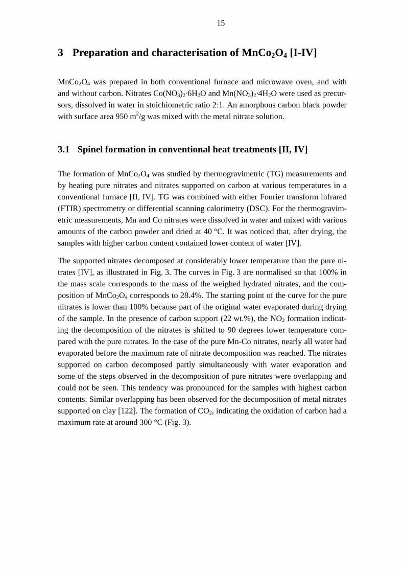
The supported nitrates decomposed at considerably lower temperature than the pure ni-trates [IV], as illustrated in Fig. 3. The curves in Fig. 3 are normalised so that 100% in the mass scale corresponds to the mass of the weighed hydrated nitrates, and the com-position of MnCo2O4 corresponds to 28.4%. The starting point of the curve for the pure nitrates is lower than 100% because part of the original water evaporated during drying of the sample. In the presence of carbon support (22 wt.%), the NO2 formation indicat-ing the decomposition of the nitrates is shifted to 90 degrees lower temperature com-pared with the pure nitrates. In the case of the pure Mn-Co nitrates, nearly all water had evaporated before the maximum rate of nitrate decomposition was reached. The nitrates supported on carbon decomposed partly simultaneously with water evaporation and some of the steps observed in the decomposition of pure nitrates were overlapping and could not be seen. This tendency was pronounced for the samples with highest carbon contents. Similar overlapping has been observed for the decomposition of metal nitrates supported on clay [122]. The formation of CO2, indicating the oxidation of carbon had a maximum rate at around 300 °C (Fig. 3).
16
Fig. 3 Mass loss and the absorbance of the strongest IR bands for formation of gases (NO2
1630 cm and CO-12 2360 cm ) as a function of temperature. -1
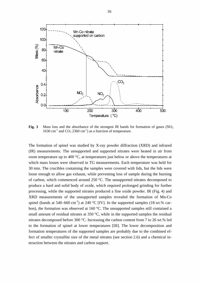
The formation of spinel was studied by X-ray powder diffraction (XRD) and infrared (IR) measurements. The unsupported and supported nitrates were heated in air from room temperature up to 400 °C, at temperatures just below or above the temperatures at which mass losses were observed in TG measurements. Each temperature was held for 30 min. The crucibles containing the samples were covered with lids, but the lids were loose enough to allow gas exhaust, while preventing loss of sample during the burning of carbon, which commenced around 250 °C. The unsupported nitrates decomposed to produce a hard and solid body of oxide, which required prolonged grinding for further processing, while the supported nitrates produced a fine oxide powder. IR (Fig. 4) and XRD measurements of the unsupported samples revealed the formation of Mn-Co spinel (bands at 540–660 cm-1) at 240 °C [IV]. In the supported samples (18 wt.% car-bon), the formation was observed at 160 °C. The unsupported samples still contained a small amount of residual nitrates at 350 °C, while in the supported samples the residual nitrates decomposed before 300 °C. Increasing the carbon content from 7 to 26 wt.% led to the formation of spinel at lower temperatures [III]. The lower decomposition and formation temperatures of the supported samples are probably due to the combined ef-fect of smaller crystallite size of the metal nitrates (see section 2.6) and a chemical in-teraction between the nitrates and carbon support.

17
Fig. 4 IR spectra of samples heated from nitrates or supported nitrates in a conventional fur-nace.
Three samples were heated for eight hours in air: at 900 °C without carbon [I, II, IV], and at 250 and 470 °C in the presence of carbon support [II]. As presented in Fig. 5, the XRD pattern of the sample prepared from nitrates at 900 °C shows sharp reflection po-sitions corresponding to MnCo2O4. The intense reflections indicate good crystallinity. The samples prepared at the lower temperatures show broader reflections of lower in-tensity shifted to higher diffraction angles relative to MnCo2O4. Lower reflection inten-sity indicates a lower degree of crystallisation. Broad reflections may be the result of small crystallites or non-uniform strain and may also mean that the individual crystals have slightly dissimilar lattice parameters [168]. The shifting of the reflections to higher angles relative to the reflection positions of MnCo2O4 has been attributed to the forma-tion of a non-stoichiometric spinel, MnCo2O4+δ (section 2.4).
TG measurements gave a value of about 0.6 for δ of the sample prepared from unsup-ported nitrates at 400 °C [IV]. Assessment of δ for the supported samples could not be done by TG, because the residual carbon content was not measurable with sufficient accuracy and carbon was oxidised simultaneously with the reduction of the metal ions [IV]. Thus, the assessments of δ were done by comparing the reflection positions. The reflection positions of the sample prepared from unsupported nitrates at 400 °C are fairly close to the reflection positions of samples with δ = 0.3–0.5 [87] and with δ = 0.6 [69]. While comparison of the reflection positions does not give an exact value of δ, it still indicates that δ must be higher than 0.3. The reflections of the samples prepared from the supported nitrates are at lower angles than those of samples prepared from ni-trates alone (Fig. 5). As the reflection positions of the supported samples lay between

18
the positions of samples with δ = 0.1 and 0.31 [87], it can be inferred that δ is smaller than 0.3. Thus, it is very probable that carbon reduces the metal ions, inducing lower non-stoichiometry. In addition to the phase MnCo2O4+δ, the sample heated at 470 °C contained stoichiometric MnCo2O4 and the sample heated at 250 °C a tetragonal spinel phase. The presence of different phases from those of the samples heat treated for 30 min can be explained by the dissimilar heating (in an open crucible) and cooling conditions (slowly within the furnace), which affect the formation of the phases [78].
Fig. 5 XRD patterns of spinel samples. Vertical lines denote the reflection positions of
MnCo2O4. Asterisks denote tetragonal spinel.

19
3.2 Spinel formation in microwave-assisted methods [I-III]
When aqueous Mn-Co nitrate solutions were heated in a microwave oven (2.45 GHz) at 650 W [I], the compounds did not absorb microwaves efficiently enough to form pure MnCo2O4. Carbon powder was therefore mixed with the aqueous solutions of the ni-trates. These samples were heated in a microwave oven with various power levels and heating times applied. High power levels, as also long heating times, resulted in a vig-orous burning of carbon and the formation of other oxide phases than spinel, while co-balt ions were reduced even as far as to metallic cobalt [I]. Less vigorous carbon oxidation and successful formation of spinel were achieved by using several short heat-ing periods (a few minutes) with cooling in between. After each heating period, the sample was weighed in order to record the mass of the specimen, and the heating was continued until the heating cycle caused no essential change in the mass.
The cyclic heating method was not found very practical, and the work was continued to find a better method of preparation [II, III]. The samples were either dried in a conven-tional furnace at 50 °C overnight or in a microwave oven where the temperature of the sample was about 100 °C. The temperature was measured by turning off the microwave heating and placing a thermocouple in the sample. After drying, the samples were placed in a conventional furnace preheated to 200 °C, where the temperature was kept for 15 min. Samples were allowed to cool to room temperature within the furnace. Most of the nitrates decomposed with this treatment. Initial carbon content in the samples was 18 wt.% [II], whereas for the pre-decomposed samples it was 7, 13, 18, or 26 wt.% [III]. After pretreatment the samples were heated in the microwave oven at power level 350 W, where they ignited, i.e. began to spark with low flames, in 0.1 to 1.1 minutes, the higher the content of carbon the sooner. The sample with lowest carbon content did not ignite at all. When the heating was interrupted the sparking reaction continued for 4–15 min, the time increasing with the carbon content. No noticeable change in the samples occurred with a subsequent microwave treatment [II]. The ignition reaction in-creased the crystallinity of the spinel formed during the pretreatment at 200 °C [III]. If the pre-decomposed samples were covered with a lid immediately after ignition in order to hinder the access to oxygen, preparation by the cyclic treatment was also possible, except when the content of carbon was high and the sample ignited after a very short heating period.
The heat treatment times of the MARS samples are listed in Table 2, and the masses of selected samples after each heating cycle are plotted in Fig. 6. On the y-axis, 100 % would represent the weighed mass of the nitrates. The lines marked with “MnCo2O4 + carbon” represent theoretical masses corresponding to MnCo2O4 with the initial carbon present and that marked with “MnCo2O4” represents MnCo2O4 alone. The starting point of the curve “b” is ~65% because part of the nitrates had decomposed during the heat treatment at 200 °C.

20
Table 2 Treatment times of MARS samples required to reach constant mass at 350 W.
Preparation route / treatment time
MW drying (h)
Drying at50 °C (h)
Decomposition at 200 °C (h)
MW treatment (min)
MW → 200 °C → MW-Ignition 1 0.5 0.1
50 °C → 200 °C → MW-Ignition 16 0.5 0.1 – 1.1*
50 °C → 200 °C → MW-Cyclic 16 0.5 10 – 14*
MW → MW-Cyclic 1 20
50 °C → MW-Cyclic 16 30 * The time depended on the amount of carbon.
Fig. 6 Mass loss during cyclic microwave treatment of nitrates supported on carbon (a) con-
taining 18 wt.% carbon and dried in microwave oven and (b) containing 7 wt.% carbon and heat treated at 200 °C before MW treatment.
An interesting feature of the microwave treatment was that the nitrates first decomposed to (Mn,Co)O, which then oxidised to MnCo2O4 [I, III] as demonstrated in Fig. 7. Simi-lar samples treated in a conventional furnace at various temperatures (150–400 °C) did not contain (Mn,Co)O, at least not (Mn,Co)O that was crystalline enough to be detected by XRD [II, III, IV]. The literature dealing with the decomposition of nitrates rarely mentions CoO or MnO as intermediates (section 2.5). These observations indicate that nitrate decomposition and spinel formation proceed in conventional and microwave ov-ens via different mechanisms.
21
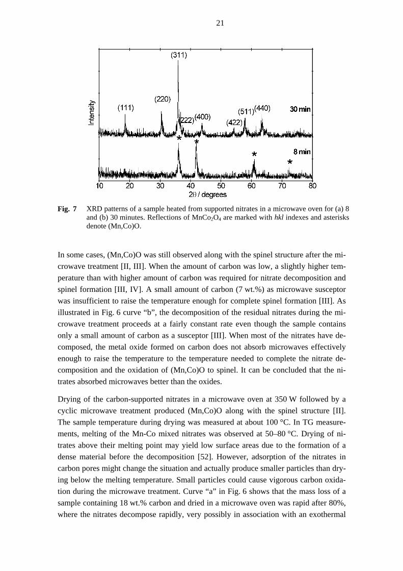
Fig. 7 XRD patterns of a sample heated from supported nitrates in a microwave oven for (a) 8
and (b) 30 minutes. Reflections of MnCo2O4 are marked with hkl indexes and asterisks denote (Mn,Co)O.
In some cases, (Mn,Co)O was still observed along with the spinel structure after the mi-crowave treatment [II, III]. When the amount of carbon was low, a slightly higher tem-perature than with higher amount of carbon was required for nitrate decomposition and spinel formation [III, IV]. A small amount of carbon (7 wt.%) as microwave susceptor was insufficient to raise the temperature enough for complete spinel formation [III]. As illustrated in Fig. 6 curve “b”, the decomposition of the residual nitrates during the mi-crowave treatment proceeds at a fairly constant rate even though the sample contains only a small amount of carbon as a susceptor [III]. When most of the nitrates have de-composed, the metal oxide formed on carbon does not absorb microwaves effectively enough to raise the temperature to the temperature needed to complete the nitrate de-composition and the oxidation of (Mn,Co)O to spinel. It can be concluded that the ni-trates absorbed microwaves better than the oxides.
Drying of the carbon-supported nitrates in a microwave oven at 350 W followed by a cyclic microwave treatment produced (Mn,Co)O along with the spinel structure [II]. The sample temperature during drying was measured at about 100 °C. In TG measure-ments, melting of the Mn-Co mixed nitrates was observed at 50–80 °C. Drying of ni-trates above their melting point may yield low surface areas due to the formation of a dense material before the decomposition [52]. However, adsorption of the nitrates in carbon pores might change the situation and actually produce smaller particles than dry-ing below the melting temperature. Small particles could cause vigorous carbon oxida-tion during the microwave treatment. Curve “a” in Fig. 6 shows that the mass loss of a sample containing 18 wt.% carbon and dried in a microwave oven was rapid after 80%, where the nitrates decompose rapidly, very possibly in association with an exothermal
22
oxidation of carbon. In samples where the mass loss occurred more slowly, spinel phase was observed without other phases. However, not only the temperature affects the dry-ing process. Drying is different and usually faster in a microwave oven than in a con-ventional furnace (section 2.7). Thus, material dried in a microwave oven may have different properties than that dried in a furnace, even though the drying temperature were the same.
The XRD reflections of the samples prepared by MARS were slightly shifted to higher diffraction angles than those with stoichiometric MnCo2O4 (Fig. 5). Comparison of the reflection positions with reported literature values [87] indicated δ to be <0.3. The shift-ing was somewhat less in the samples initially containing highest amount of carbon and in those prepared by the ignition reaction [II, III]. The reduced shifting may be due to more vigorous burning of carbon and conditions that are more reducing. The reflection intensities of the MARS samples (Fig. 5) are closely similar to those for the samples heated at 250 and 470 °C for 8 hours, slightly higher than those for the pure nitrates heated at 400 °C for 30 min, and clearly higher than those for the supported nitrates heated at 400 °C for 30 min. This demonstrates that MnCo2O4 with relatively high de-gree of crystallisation can be prepared in a microwave oven in a short time (see Ta-ble 2).
3.3 Carbon oxidation
If all initial carbon were to remain in the samples throughout the preparation process, the spinel-carbon powders would contain 20–56 wt.% carbon, depending on the amount of initial carbon. Carbon contents of the samples were determined with a Leco SC-444 analyser on the basis of infrared absorption. In the samples heated at 250 and 470 °C for eight hours, the initial carbon was almost totally oxidised [II]. In the samples heated up to 400 °C the amount of carbon decreased nearly linearly with the increase in tempera-ture. The MARS samples contained 4–22 wt.% carbon [I-III], indicating that most car-bon is oxidised during the preparation.
TG measurements revealed that the carbon alone did not start to burn below 550 °C in air. During the heating of the nitrate-impregnated carbon, 10–20% of the initial amount of carbon was oxidised at 200 °C [II, III]. Likewise, TG-FTIR measurements showed the formation of carbon dioxide from the supported samples below 200 °C (Fig. 3) [IV]. A local maximum in the oxidation rate was observed at 200 °C partly simultaneously with the nitrate decomposition, and the highest oxidation rate was seen at 300 °C after the nitrate decomposition. It can be concluded that, Mn-Co nitrate decomposition en-hanced the oxidation of carbon, but most of the carbon was oxidised after the formation of Mn-Co spinel oxide.

23
No oxidation of carbon was observed when carbon powder alone was heated in a mi-crowave oven under similar conditions to the MARS preparations. Although carbon can be oxidised at lower temperatures in a microwave oven than in a conventional furnace [114], under these conditions carbon did not absorb enough microwave energy to reach the necessary temperature for oxidation to occur. When the nitrate-impregnated carbon samples were heated in a microwave oven, 20 to 90% of the initial carbon became oxi-dised, varying with the initial carbon content, pretreatment, and microwave treatment [II, III]. The higher the initial carbon content, the more carbon was oxidised during the microwave treatment. Because carbon absorbs microwaves strongly, higher carbon con-tent results in higher temperature during the microwave heating, which then accelerates the oxidation of carbon. Further, the ignition reaction consumed more carbon than the cyclic preparation [II]. Since the preparation methods consuming most carbon were shortest, the carbon consumption cannot be due to prolonged preparation time but rather to more vigorous oxidation of carbon.
3.4 Surface area and particle size
Specific surface areas of the catalysts were measured by Brunauer-Emmet-Teller (BET) method. Catalysts prepared at 250, 470, and 900 °C gave surface areas of 32, 5, and 0.7 m2/g, respectively [II]. These surface areas and their decrease with increasing tem-perature are very similar to the values for Co3O4 prepared from Co-nitrate [169]. The spinel-carbon powders prepared by MARS had combined surface areas correlating with their carbon contents: as the carbon content increased from 4 to 16 wt.% the measured surface areas of the spinel-carbon powders increased nearly linearly from 40 to 165 m2/g [I-III] (see Fig. 8). In most cases the combined surface areas of the MARS samples could be predicted from the final mass of the samples, because (i) the smaller was the mass of the final product the smaller was the amount of residual carbon, and (ii) the combined surface areas increased with the carbon content.
In two MARS samples the amount of carbon was 22 wt.%, but their surface area was not larger than 165 m2/g. These samples were prepared by drying of the supported ni-trates in a microwave oven followed by the cyclic microwave treatment. In addition to the ratio of carbon to metal ion [43g], also the rate of carbon oxidation may affect the surface area of metal oxide: samples prepared with higher carbon oxidation rate have been reported to have smaller surface area [51]. Comparison with the MnCo2O4 pow-ders prepared by other methods (Table 1) is not very helpful since the surface areas measured in this work are the combined surface areas of the spinel and carbon. If car-bon were to be removed, for example by washing with water or by heat treatment, the surface area of the spinel would probably change.

24
Fig. 8 Combined specific surface area vs. carbon content of spinel-carbon powders prepared
by MARS.
Surface morphologies and particle size were assessed by scanning electron microscopy (SEM) and transmission electron microscopy (TEM). SEM images (Fig. 9a) of the sam-ple heated at 900 °C revealed particle sizes ranging from 0.3 to 3 µm [I]. The samples heated at 470 and 250 °C had considerably smaller particles: smaller than 100 and 50 nm, respectively [II]. Particles of the MARS samples were mostly a few nanometres in diameter, with some agglomerates smaller than 30 nm [II, III]. An example is given in Figures 9b and 10. Figure 10 also shows that the spinel particles (dark areas) are dis-tributed and dispersed through the residual carbon (lighter areas).
a) b) Fig. 9 SEM micrographs of samples prepared (a) at 900 °C from pure nitrates, (b) by MARS
from supported nitrates.

25
Fig. 10 TEM micrograph of a sample prepared by MARS.
3.5 Catalytic activity towards ORR [I-III]
The catalytic activities towards ORR [I-III] were evaluated by current-potential, i.e. po-larisation, measurements in a half-cell set-up (Fig. 11) with 6 M KOH as the electrolyte. The set-up comprises three-electrodes: the counter, the reference, and the working elec-trode. The working electrode containing the catalyst was in contact with air [I] or oxy-gen [II, III] and was loaded by a stepwise increasing current. The potential at steady state was measured in relative to a Hg/HgO reference electrode. The counter electrode was of nickel plate or mesh. The measurements were done at 60 [I] or 50 °C [II, III].
Fig. 11 Drawing of the electrochemical half-cell.

26
Polarisation measurements give valuable information for fuel cell applications because they indicate whether a catalyst is actually suitable for fuel cell electrode preparation. The working electrodes were similar to the fuel cell electrodes described in section 2.2 and Fig. 2, consisting of an electric conductor (nickel screen) and diffusion and active layers. The diffusion layer contained PTFE and carbon, while the active layer contained these and the catalyst. The amount of the catalyst in the electrodes was ~12 mg/cm2. Two methods for the electrode preparation were applied. In the pressing method, the dry powdery materials were pressed onto the nickel screen [I] and heat-treated at 340 °C. In the rolling method [28, 170], described in papers II and III, pastes made from the electrode materials were rolled into flat sheets, which were then rolled on the nickel screen, pressed, dried, and heat-treated at 320 °C. The electrodes were then assembled in the half-cell configuration for electrochemical assessment.
Fig. 12 depicts the polarisation curves of the electrodes. The closer to zero is the poten-tial, i.e. the smaller the potential drop at a certain current density, the better is the cata-lytic activity for ORR. Comparison of the current densities at –200 mV vs. Hg/HgO reveals that the samples prepared at 250 and 470 °C from the supported nitrates gave twice as high current densities as the sample prepared at 900 °C [II]. These samples did not, however, show better catalytic activity than the carbon alone. The MARS samples showed four times as high current densities as the sample prepared at 900 °C and twice as high current densities as carbon or the samples prepared at 250 or 470 °C. This dem-onstrates the positive effect of the spinel with small particle size distributed on carbon. During the 300 h measurement, the potential drop at a current density of 100 mA/cm2 for the electrodes containing the best catalysts was 0.03–0.09 mV/h [II, III].
Fig. 12 Polarisation curves of electrodes containing MnCo2O4 prepared by different methods
for oxygen reduction reaction.

27
As shown in Fig. 13, for the MARS samples with combined surface areas between 90–165 m2/g, the potential at 100 mA/cm2 was about –130 mV vs. Hg/HgO. When the spe-cific surface area decreased below 90 m2/g, the catalytic activity decreased as well, but increasing the surface areas beyond this value did not result in better performance of the electrodes [II, III]. Similar findings have been reported earlier [28]. Probably an exten-sive part of the surface area of the carbon support remains non-utilised [49]. As Fig. 8 depicts, a carbon amount of approximately 10 wt.% in spinel-carbon powders gives a combined surface area of about 100 m2/g. It can be concluded that, under the conditions employed, 10 wt.% carbon in a spinel-carbon final product is adequate for obtaining the maximum catalytic activity towards ORR.
The samples with combined specific surface areas between 90 and 165 m2/g and high activity (Fig. 13) were prepared from the nitrates supported on carbon initially contain-ing 13 or 18 wt.% carbon and pretreated by drying in a conventional furnace at 50 °C or heating at 200 °C. The MARS samples with lowest surface areas (<90 m2/g) and cata-lytic activities were those prepared with the lowest (7C) and highest (26C) amounts of carbon [III] and with drying of samples in a microwave oven (M1, M2) [II]. The sample with high surface area of 160 m2/g (M3) but lower activity than the other high surface area samples contained (Mn,Co)O along with the spinel phase, and this might explain the lower activity [II]. Further, it was noticed that catalytic activity increased with the impregnation time [I].
Fig. 13 Potential at 100 mA/cm2 vs. specific surface area of the catalysts in the electrodes. M1–M3 denote samples dried in a microwave oven. 26C and 7C denote samples prepared from supported nitrates with carbon contents of 26 and 7 wt.%. The samples marked with temperature denote samples prepared in a conventional furnace for eight hours.

28
The MARS samples showed voltage drops of 50 and 60 mV when the current density was increased from 50 to 100 mA/cm2 and from 100 to 200 mA/cm2, respectively (Fig. 12). Some other Co-rich spinels [53, 111, 112, 171-174] measured in 5–7 M KOH and at 20–60 °C have shown corresponding voltage drops of 20–50 mV and 20–90 mV. However, as discussed in section 2.3, several factors including catalyst loading and electrode structure affect the fuel cell operation and polarisation curves. Thus, catalyst activities can actually be compared only as long as all other conditions are kept constant during electrode preparation and measurement. At present there is no standard method to measure the catalytic activity for fuel cell applications, which makes it difficult to compare the catalysts.
3.6 Outlook
This work has demonstrated that MnCo2O4 composed of small particles and of good catalytic activity can be prepared by microwave-assisted methods requiring only a few minutes and a short pretreatment. A major problem was that the carbon powder that was employed began to burn vigorously and reduced the metal ions, and cobalt ions even to metallic state. Thus, preparation methods that ensured slower oxidation of carbon had to be developed. In future, testing of different types of carbon might throw light on this problem. Since the Mn-Co nitrates absorb microwaves better than the metal oxides that are formed (section 3.2), better conditions for the preparation might be achieved by op-timising the oxide to nitrate ratio. This ratio could be varied by changing the pre-treatment temperature and the time in a conventional furnace. Also, precursors that do not enhance carbon oxidation as much as nitrates might be an advantage. Moreover, dif-ferent solvents and different concentrations of precursors in the solutions should be tested, and drying temperature and time should be optimised. Some researchers [51] have noted that when metal precursors are impregnated into carbon for the preparation of high surface area metal oxides, the carbon should not burn totally away before the metal oxides are formed. Thus, the temperatures for the precursor decomposition and carbon oxidation should be determined, by thermogravimetric measurements for exam-ple, to assess the suitability of the precursors for this kind of synthesis.

29
4 Preparation and characterisation of doped Raney Ni [V]
4.1 Preparation method
Raney nickel catalysts were prepared from metallic powders of nickel and aluminium with weight ratio 1:1. The amount of added dopant metal – Fe, Cu, Ti, Cr, or La – was 2 wt.%, and the aluminium content was correspondingly decreased to 48 wt.%. The dopants were added in their metallic state, except for La, which was applied as nitrate. Usually, Al-Ni alloy is prepared by quenching Ni-Al melt, but in this work nickel, alu-minium, and a dopant metal were mixed and alcohol was added until a paste was achieved. The paste was then extruded to a thickness of 1.2 mm with a roller and heat-treated at 700 °C under hydrogen atmosphere for 7 h. The samples were cooled down in a water-cooling zone of the furnace with a continuous flow of nitrogen gas. The alloys formed in this way were ground in a mortar and sieved to 75 µm. Aluminium was leached from the alloys in 6 M KOH at 80 °C. The leached samples were washed with deionised water till the pH value was approximately 7. Usually the freshly leached Ra-ney nickel is dried in vacuum and then deactivated, but here the samples were stored immersed in water to limit oxidation by air.
4.2 Properties
Energy dispersive X-ray spectroscopy (EDX) measurements revealed that the content of the residual aluminium in the catalysts was relatively high: on average 18 atomic % (14 wt.%). The contents of oxygen and dopants were 34–46 at.% and 1–3 at.%, respec-tively. Most alloying metals undergo partial or even full oxidation during leaching [154], but the rather high concentration of oxygen and aluminium suggested that the alloy formation, leaching process, washing procedure, or storage was not fully success-ful and that oxide films were formed on the surface of the catalyst particles. X-ray dif-fraction patterns (Fig. 14) were recorded from the wet samples under a protecting film and revealed reflections of cubic Ni accompanied by weak reflections of aluminium hy-droxide. Raney nickel without dopants showed the sharpest and most intense reflec-tions, indicating the largest crystallite size and high crystallinity. The reflections of Ni in the Cr- and Ti-doped samples were slightly broader than in other samples indicating smaller crystallite size.

30
Fig. 14 XRD patterns of the Raney nickel catalysts with dopants. Asterisks denote aluminiumhydroxide.
The Raney nickel catalysts consisted of particles of irregular shape, ranging in size from a few microns up to ~50 µm. A typical SEM image of the spongy feature of Raney nickel catalyst after the leaching step is shown in Fig. 15. Surface areas of the precursor nickel and aluminium metal powders were about 0.5 m2/g and pore volumes were neg-ligible. The Raney nickel catalysts had surface areas more than a hundred times higher, ranging from 50 to 80 m2/g and being highest for the Cr-doped Raney nickel. Typical surface areas reported for doped Raney nickel catalysts applied in AFC range between 40 and 80 m2/g [155, 156, 158, 161].
Fig. 15 SEM micrograph of a Raney nickel catalyst.
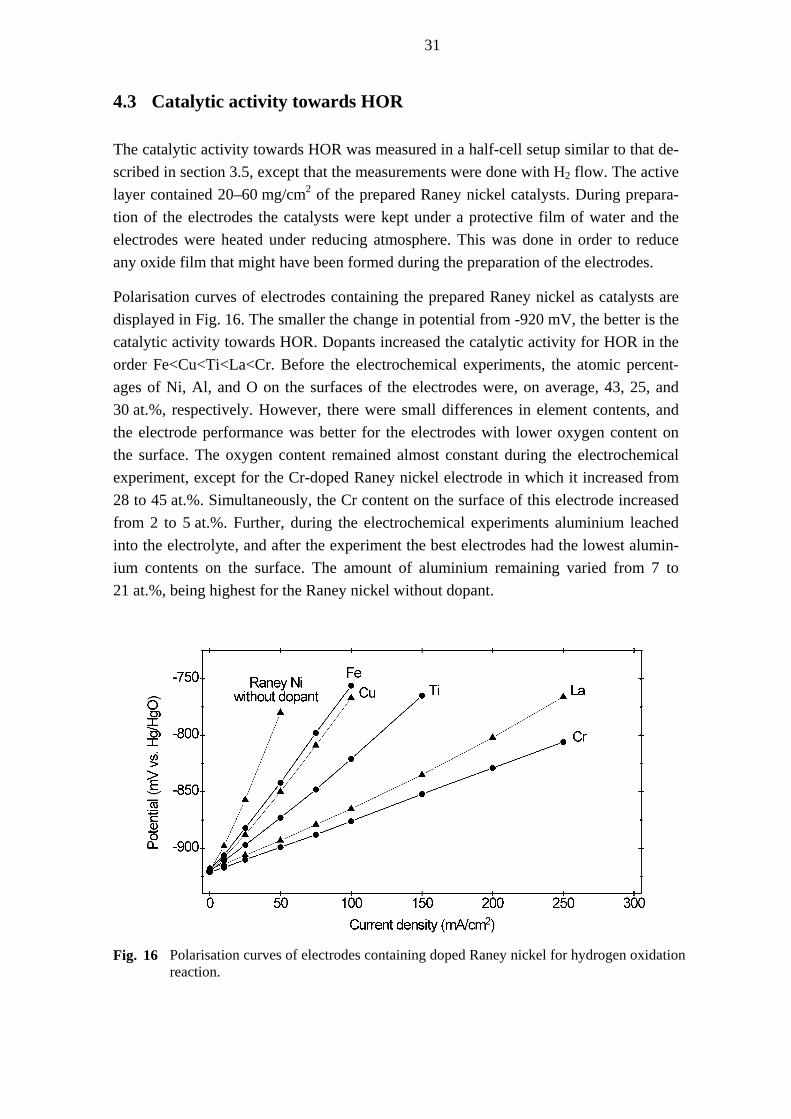
31
4.3 Catalytic activity towards HOR
The catalytic activity towards HOR was measured in a half-cell setup similar to that de-scribed in section 3.5, except that the measurements were done with H2 flow. The active layer contained 20–60 mg/cm2 of the prepared Raney nickel catalysts. During prepara-tion of the electrodes the catalysts were kept under a protective film of water and the electrodes were heated under reducing atmosphere. This was done in order to reduce any oxide film that might have been formed during the preparation of the electrodes.
Polarisation curves of electrodes containing the prepared Raney nickel as catalysts are displayed in Fig. 16. The smaller the change in potential from -920 mV, the better is the catalytic activity towards HOR. Dopants increased the catalytic activity for HOR in the order Fe<Cu<Ti<La<Cr. Before the electrochemical experiments, the atomic percent-ages of Ni, Al, and O on the surfaces of the electrodes were, on average, 43, 25, and 30 at.%, respectively. However, there were small differences in element contents, and the electrode performance was better for the electrodes with lower oxygen content on the surface. The oxygen content remained almost constant during the electrochemical experiment, except for the Cr-doped Raney nickel electrode in which it increased from 28 to 45 at.%. Simultaneously, the Cr content on the surface of this electrode increased from 2 to 5 at.%. Further, during the electrochemical experiments aluminium leached into the electrolyte, and after the experiment the best electrodes had the lowest alumin-ium contents on the surface. The amount of aluminium remaining varied from 7 to 21 at.%, being highest for the Raney nickel without dopant.
Fig. 16 Polarisation curves of electrodes containing doped Raney nickel for hydrogen oxidation
reaction.

32
At -875 mV, Cr-, La-, and Ti-doped Raney nickel gave 6, 4.7, and 2.8 times as high cur-rent densities as the Raney nickel without dopant. The activity and nature of these cata-lysts were further examined by altering the catalyst load. The catalytic activity of Ti-doped Raney nickel showed no change as the load was altered, whereas La-doped Ra-ney nickel showed the best catalytic activity at medium catalyst load. The activity of the Cr-doped Raney nickel was enhanced with increasing catalyst load. When the catalyst loading was increased 1.6 and 2.2 fold from 29 mg/cm2 the current densities at -875 mV were 1.6 and 3 times as high, respectively.
The increased activity of the Cr-based Raney nickel electrodes may be due to the sur-face enrichment of the Cr particles. Figure 17 shows a SEM micrograph of an electrode containing the prepared Cr-doped Raney nickel before and after the electrochemical ex-periment. During the electrochemical experiment, hexagonal shaped particles, 1–6 µm in size, became exposed on the surface and were distributed throughout the active sur-face of the electrode (Fig. 17b). These particles were identified as chromium oxide. Similar aggregation of titanium oxide particles was observed for the Ti-doped Raney nickel electrode. This kind of particle agglomeration during electrochemical experi-ments has been reported for Pt [175] and Pt-Co [6, 176] electrocatalysts as well, and can be explained in terms of the migration of the small crystallites by virtue of surface en-ergy, potential gradients, and movement of the H atoms and OH– ions.
a)
b)
Fig. 17 SEM micrographs of Cr-doped Raney nickel electrode (a) before and (b) after the elec-
trochemical experiment.
Figure 16 shows that when the current density is increased from 50 to 100 mA/cm2 and from 100 to 200 mA/cm2, the Cr-doped Raney nickel undergoes voltage change of 20 and 45 mV, respectively. The corresponding values for the higher Cr-load were 10 and 25 mV (data not shown). During the electrochemical experiment lasting 100 h, the dete-rioration rates for Cr-, Ti-, and La-doped Raney nickel electrodes at 100 mA/cm2 were 0.05, 0.18, and >1 mV/h, respectively. For some other Raney nickel electrodes doped with Cr or Ti, or to which Cu2O has been added, corresponding voltage drops of 5–

33
15 mV and 5–25 mV [155, 156, 158, 163, 166] and long term stabilities of 0.01–0.02 mV/h [158, 163, 166] were measured in 6 M KOH at 50–80°C. However, as dis-cussed in section 3.5, since these measurements were done with different loadings and electrode preparations, the catalytic activities of the catalysts are not entirely compara-ble.
One explanation for the higher catalytic activity resulting from the doping with Cr, La, and Ti than with Cu and Fe may be related to the Brewer-Engel valence-bond theory for bonding in metals and intermetallic phases. Significant synergism has been reported to occur in the hydrogen evolution reaction (HER) when early transition metals with empty or half-filled d-orbitals were alloyed with late transition metals that have inter-nally paired d-electrons not available for bonding in the pure phase [177]. An important feature of these kinds of alloy combinations is that hydrogen storage capacity is high so that they can be used as negative electrodes in nickel-metal hydride batteries and as electrocatalysts for anodes in fuel cells [178-181].
This work has demonstrated that dopants have a significant effect on the catalytic activ-ity of Raney nickel towards HOR. Use of multi-component dopants could be favourable in the preparation of more stable and active catalysts [157]. The conditions of the syn-thesis were not varied or optimised in this work as the main purpose was to compare the effect of different dopants. However, at least the cooling rate of the alloy and the leach-ing temperature and time have a significant effect on the catalyst properties (sec-tion 2.8). Varying the conditions of the synthesis, such as mixing and homogenising steps, duration and temperature of the heat treatment, and leaching and washing proc-esses might lead to better catalytic activity and stability.
34
5 Conclusions
The objective of this work was to develop methods for the preparation of catalysts for alkaline fuel cells (AFC): MnCo2O4 for oxygen reduction reaction (ORR) on the cath-ode and Raney nickel for hydrogen oxidation reaction (HOR) on the anode.
For the preparation of MnCo2O4, aqueous solutions of mixed Mn-Co nitrates were im-pregnated into carbon powder. Carbon was used because (i) it is usually applied in the AFC electrode preparation and has moderate catalytic activity towards ORR, (ii) it can be used as a surface-enhancing agent to produce high surface area powders, (iii) it can decrease the decomposition temperatures of metal complexes allowing lower prepara-tion temperatures, (iv) it absorbs microwaves rapidly and can be applied as an internal heater in the microwave-assisted synthesis. Use of carbon was found to have clear ad-vantages. The Mn-Co nitrates supported on carbon began to decompose at lower tem-peratures and produced less non-stoichiometric spinel than the preparation without carbon. Further, spinel preparation in the microwave oven required a minimum amount of carbon (13 wt.%) as an internal heater.
The metal nitrates and oxides enhanced the oxidation of carbon, and most of the carbon was oxidised during the preparation. Long continuous heating of the nitrate-impregnated carbon in a microwave oven resulted in vigorous burning of the carbon re-sulting in the formation of other phases than spinel. Spinel formation became successful when several heating periods of a few minutes with cooling in between were applied. The formation of spinel in the microwave oven occurred via (Mn,Co)O, but this inter-mediate was not observed during heating in a conventional furnace. The microwave treatment could be shortened to one minute if the carbon-supported nitrates had first been dried in a conventional furnace at 50 °C followed by the decomposition of nitrates at 200 °C. During the microwave treatment, an ignition reaction occurred, usually in less than one minute, and the reaction was allowed to proceed freely, usually for about ten minutes, in open air until it ceased by itself. MnCo2O4 on carbon prepared by this method contained ~10 wt.% residual carbon and had particle size less than 30 nm, and the combined surface area of the spinel-carbon powder was about 100 m2/g.
The residual amounts of carbon in the spinel-carbon catalysts varied with the initial car-bon content, pretreatment, and microwave treatment. As the residual amount of carbon in the spinel-carbon powder decreased, the combined specific surface area decreased almost linearly. The catalytic activity of the MARS samples was enhanced when the combined surface area of the spinel-carbon powders was increased to 90 m2/g, but in-creasing the surface area beyond this value did not enhance the activity. The threshold surface area was reached with ~10 wt.% carbon in the final spinel-carbon catalyst.

35
Doped Raney nickel was prepared by leaching Al from Ni-Al-dopant alloys. The doped Raney nickel catalysts displayed surface areas of 50–80 m2/g. The highest surface area was achieved when Cr was added as dopant. The degree of crystallisation was lowest for the Cr- and Ti-doped catalysts and highest for the Raney nickel without dopants. Doping increased the catalytic activity of the Raney nickel in the order Fe<Cu<Ti<La<Cr. Doping with Cr and Ti showed the best long-term stability during measurements of 100 h. During the electrochemical experiment, Cr and Ti particles ag-glomerated as metal oxides on the surface of the electrodes, and simultaneously the sur-face content of chromium increased significantly. High contents of aluminium and oxygen in the samples indicated that the preparation process was not fully successful. Optimising the preparation conditions could lead to better catalytic activity.

36
REFERENCES
1. Cropper, M.A.J., Geiger, S., Jollie, D.M., J. Power Sources 131 (2004) 57.
2. Richardson, J.T., Principles of Catalyst Development, Plenum Press, New York, 1992, a) p. 1. b) p. 121. c) pp. 28-35.
3. Landau, M.V. in Handbook of Porous Solids Vol. 3, Schüth, F., Sing, K.S.W., Weitkamp, J. (eds.), Wiley-VCH Verlag GmbH, Weinheim, Germany 2002, pp. 1677-1752.
4. Linden, D. in Handbook of Batteries, Linden, D., Reddy, T.B. (eds), 3rd ed., McGraw-Hill, USA 2002, p. 1.4.
5. Züttel, A., Materials Today 6 (2003) 24.
6. Ogden, J.M. in Handbook of Fuel Cells Vol. 3, Fuel Cell Technology and Applications, Vielstich, W., Lamm, A., Gasteiger, H.A. (eds), John Wiley & Sons Ltd., Milan 2003, pp. 3-24.
7. Kiros, Y., Myrén, Schwartz, S., Sampathrajan, A., Ramanathan, M., Int. J. Hydrogen Energy 24 (1999) 549.
8. Kaufman, A., Gibbard, H.F. in Handbook of Batteries, Linden, D., Reddy, T.B. (eds), 3rd ed., McGraw-Hill, USA 2002, pp. 43.7-12.
9. Appleby, A.J., J. Power Sources 29 (1990) 3.
10. Hamnett, A. in Handbook of Fuel Cells Vol. 1, Fundamentals and Survey of Systems, Vielstich, W., Lamm, A., Gasteiger, H.A. (eds), John Wiley & Sons Ltd., Milan 2003, pp. 36-44.
11. McLean, G.F., Niet, T., Pince-Richard, S., Djilali, N., Int. J. Hydrogen Energy 27 (2002) 507.
12. Cifrain, M., Kordesch, K. in Handbook of Fuel Cells Vol. 1, Fundamentals and Survey of Systems, Vielstich, W., Lamm, A., Gasteiger, H.A. (eds), John Wiley & Sons Ltd., Milan 2003, pp. 267-280.
13. Kordesch, K., Hacker, V., Gsellmann, J., Cifrain, M., Faleschini, G., Enzinger, P., Frankhauser, R., Ortner, M., Muhr, M., Aronson, R.R., J. Power Sources 86 (2000) 162.
14. Kordesch, K., Gsellmann, J., Cifrain, M., Voss, S., Hacker, V., Aronson, R.R., Fabjan, C., Hejze, T., Daniel-Ivad, J., J. Power Sources 80 (1999) 190.
15. Schulze, M., Gülzow, E., J. Power Sources 127 (2004) 252.
16. Strasser, K. in Handbook of Fuel Cells Vol. 4, Fuel Cell Technology and Applications, Vielstich, W., Lamm, A., Gasteiger, H.A. (eds), John Wiley & Sons Ltd., Milan 2003, pp. 774-788.
17. Gülzow, E., J. Power Sources 61 (1996) 99.
18. Gülzow, E., Schulze, M., J. Power Sources 127 (2004) 243.

37
19. Kordesch, K., Cifrain, M. in in Handbook of Fuel Cells Vol. 4, Fuel Cell Technology and Applications, Vielstich, W., Lamm, A., Gasteiger, H.A. (eds), John Wiley & Sons Ltd., Milan 2003, pp. 789-793.
20. De Geeter, E., Mangan, M., Spaepen, S., Stinissen, W., Vennekens, G., J. Power Sources 80 (1999) 207.
21. Yeager, E., Electrochim. Acta 29 (1984) 1527.
22. Kordesch, K., Hacker, V. in Handbook of Fuel Cells Vol. 4, Fuel Cell Technology and Applications, Vielstich, W., Lamm, A., Gasteiger, H.A. (eds), John Wiley & Sons Ltd., Milan 2003, pp. 765-773.
23. Acres, G.J.K., Frost, J.C., Hards, G.A., Potter, R.J., Ralph, T.R., Thompsett, D., Burstein, G.T., Hutching, G.J., Catal. Today 38 (1997) 393.
24. Kiros, Y., Characterisation and Optimisation of Alkaline Fuel Cell Electrodes and Electrocatalysts, Thesis, Royal Institute of Technology, Stockholm, 1996.
25. Kiros, Y., J. Electrochem. Soc. 143 (1996) 2152.
26. Kiros, Y., Lindström, O., Kaimakis, T., J. Power Sources 45 (1993) 219.
27. Kordesch, K., Tomantschger, K.,1989, Pat. WO8902660.
28. Kiros, Y., Schwartz, S., J. Power Sources 36 (1991) 547.
29. Kivisaari, J., Lamminen, J., Lampinen, M.J., Viitanen, M., J. Power Sources 32 (1990) 233.
30. Lamminen, J., Kivisaari, J., Lampinen, M.J., Viitanen, M., Vuorisalo, J., J. Electrochem. Soc. 138 (1991) 905.
31. Wang, C., Appleby, J., Cocke, D., J. Electrochem. Soc. 151 (2004) A260.
32. Kannan, A.M., Design and Characterisation of Bifunctional Oxygen Electrodes for Metal / Air Batteries, Thesis, Indian Institute of Science, Bangalore, 1990.
33. Vielstich, W. in Handbook of Fuel Cells Vol. 1, Fundamentals and Survey of Systems, Vielstich, W., Lamm, A., Gasteiger, H.A. (eds), John Wiley & Sons Ltd., Milan 2003, pp. 26-30.
34. Linden, D., Reddy, T.B. in Handbook of Batteries, Linden, D., Reddy, T.B. (eds), 3rd ed., McGraw-Hill 2002, USA, p. 42.5.
35. Pirjamali, M., Kiros, Y., J. Power Sources 109 (2002) 446.
36. Tomantschger, K., Kordesch, K.V., J. Power Sources 25 (1989) 195.
37. Viitanen, M., Theoretical and Experimental Study of Air and Hydrogen Electrodes, Thesis, University of Turku, 1993.
38. Kivisaari, J., Preparation, Characterisation and Modelling of Air Electrodes for Alkaline Fuel Cells, Thesis, Royal Institute of Stockholm, 1992.
39. Restovic, A., Poillerat, G., Chartier, P., Gautier, J.L., Electrochim. Acta 40 (1995) 2669.

38
40. Viitanen, M., Lampinen, M.J., J. Power Sources 32 (1990) 207.
41. Kiros, Y., Quatrano, T., Björnbom, P., Electrochem. Commun. 6 (2004) 526.
42. Jo, J.-H., Moon, S.-K., Yi, S.-C., J. Appl. Electrochem. 30 (2000) 1023.
43. Kinoshita, K., Carbon, Electrochemical and Physicochemical Properties, John Wiley & Sons, New York, 1988, a) pp. 1-19, b) 86-173, c) 187-193, d) 226-292, e) 334-337, f) 360-368, g) 390-391, h) 397-400.
44. Sugawara, M., Ohno, M., Matsuki, K., J. Mater. Chem. 7 (1997) 833.
45. Rios, E., Gautier, J.-L., Poillerat, G., Chartier, P., Electrochim. Acta 44 (1998) 1491.
46. Restovic, A., Ríos, E., Barbato, S., Ortiz, J., Gautier, J.L., J. Electroanal. Chem. 522 (2002) 141.
47. Alcaide, F., Brillas, E., Cabot, P.-L., J. Electroanal. Chem. 566 (2004) 235.
48. Alcaide, F., Brillas, E., Cabot, P.-L., J. Electrochem. Soc. 149 (2002) E64.
49. Appleby, A.J., Marie, J., Electrochim. Acta 24 (1979) 195.
50. Moon, J., Awano, M., Takagi, H., Fujishiro, Y., J. Mater. Res. 14 (1999) 4594.
51. Schwickardi, M., Johann, T, , Schmidt, W., Schüth, F., Chem. Mater. 14 (2002) 3913.
52. Lapham, D.P., Tseung, A.C.C., J. Mater. Sci. 39 (2004) 251.
53. King, W.J., Tseung, A.C.C., Electrochim. Acta 19 (1974) 485.
54. Greenwood, N.N., Earnshaw, A., Chemistry of the Elements, Butterworth Heinemann, Great Britain, 1997, pp. 247-249.
55. Tarasevich, M.R., Bagotskii, V.S., Efremov, B.N., Geterog. Katal. 4 (1979) 367.
56. Burshtein, R.Kh., Vilinskaya, V.S., Bulavina, N.G., Shepelev, V.Ya., Elektrokhimiya 14 (1978) 907.
57. Rios, E., Chartier, P., Gautier, J.-L., Solid State Sci. 1 (1999) 267.
58. Rios, E., Poillerat, G., Koenig, J.F., Gautier, J.L., Chartier, P., Thin Solid Films 264 (1995) 18.
59. Pirogova, G.N., Panich, N.M., Korosteleva, R.I., Voronin, Yu.V., Popova, N.N., Russ. Chem. Bull. 49 (2000) 1536.
60. Cheshkova, K.Ts., Mehandjiev, D.R., Bulg. Chem. Commun. 26 (1993) 115.
61. Sergeeva., O.V., Bol’shakov, A.M., Konin, G.A., Khmelevskaya, L.V., Russ. J. Inorg. Chem. 44 (1999) 1045.
62. Liang, Q., Chen, K., Hou, W., Yan, Q., Appl. Catal. A 166 (1998) 191.
63. Yan, Q., Chen, K., Liang, Q., 1997, Pat. CN1157756.
64. Shimizu, Y., Shiotsuka, M., Jpn. J. Appl. Phys. 41 (2002) 6243.
39
65. Umadevi, P., Nagendra, C.L., Sens. Actuators A 96 (2002) 114.
66. Nagatomo, N., Endo, K., Yonezawa, T., Key Eng. Mater. 159-160 (1999) 305.
67. Ando, M., Kamada, K., Kadono, K., Ohta, K., Tawa, K., Tanaka, T., US Pat. Appl. US2002024752.
68. Joy, P.A., Date, S.K., J. Magn. Magn. Mater. 210 (2000) 31.
69. Gautier, J.L., Fuentealba, R., Cabezas, C., Z. Phys. Chem. 126 (1981) 71.
70. Andrushkevich, T.V., Boreskov, G.K., Popovskii, V.V., Plyas-ova, L.M., Karakchiev, L.G., Ostan'kovich, A.A., Kinet. Katal. 9 (1968) 1244.
71. Dyakova, B., Mehandjiev, D., Izv. Khim. 23 (1990) 516.
72. Stoilova, D., Koleva, V., C. R. Acad. Bulg. Sci. 53 (2000) 57.
73. Jiménez Mateos, J.M., Morales, J., Tirado, J.L., J. Solid State Chem. 82 (1989) 87.
74. Dimitar, G., Klissurski, D.G., Uzunova, E.L., Appl. Surf. Sci. 214 (2003) 370.
75. Ravindranathan, P., Mahesh, G.V., Patil, K.C., J. Solid State Chem. 66 (1987) 20.
76. Sivasankar, B.N., Govindarajan, S., Mater. Res. Bull. 31 (1996) 47.
77. Hong, K.-P., Park, H.-S., Kwon, Y.-U., Bull. Korean Chem. Soc. 20 (1999) 163.
78. de Vidales, J.L.M., Vila, E., Rojas, R.M., Carcía-Martínez, O., Chem. Mater. 7 (1995) 1716.
79. de Vidales, J.L.M., García-Martínez, O., Vila, E., Rojas, R.M., Torralvo, M.J., Mater. Res. Bull. 28 (1993) 1135.
80. Rojas, R.M., Vila, E., García, O., de Vidales, J.L.M., J. Mater. Chem. 4 (1994) 1635.
81. Yamamoto, N., Higashi, S., Kawano, S., Achiwa, N., J. Mater. Sci. Lett. 2 (1983) 525.
82. Jang, Y.I., Wang, H.F., Chiang, Y.M., J. Mater. Chem. 8 (1998) 2761.
83. Brenet, J., Koenig, J.F., Z. Phys. Chem. 98 (1975) 351.
84. Vasil'ev, G.P., Pakhomov, L.A., Ryabova, L.A., Thin Solid Films 66 (1980) 119.
85. Gautier, J.L., Cabezas, C., Barbato, S., Electrochim. Acta 26 (1981) 1377.
86. Gautier, J.L., Cabezas, C., J. Electroanal. Chem. 159 (1983) 137.
87. Koenig, J.F., Brenet, J., C.R. Acad. Sci. B: Sci. Phys. 283 (1976) 71.
88. Roginskaya, Yu.E., Morozova, O.V., Lubnin, E.N., Ulitina, Yu.E., Lopukhova, G.V., Trasatti, S., Langmuir 13 (1997) 4621.
89. Yuvaraj, S., Fan-Yuan, L., Tsong-Huei, C., Chuin-Tih, Y., J. Phys. Chem. B 107 (2003) 1044.
90. Centi, C., Ciambelli, P., Perathoner, S., Russo, P., Catal. Today 75 (2002) 3.

40
91. Heck, R.M., Catal. Today 53 (1999) 519.
92. Armor, J.N., Catal. Today 26 (1995) 99.
93. Leskelä, M., Maijanen, A., Niinistö, L., Kem. - Kemi 14 (1987) 727.
94. Maneva, M., Petroff, N., J. Therm. Anal. 36 (1990) 2511.
95. Gallagher, P.K., Schrey, F., Prescott, B., Thermochim. Acta 2 (1971) 405.
96. Cseri, T., Békássy, S., Kenessey, G., Liptay, G., Figueras, F., Thermochim. Acta 288 (1996) 137.
97. Nohman, A.K.H., Ismail, H.M., Hussein, G.A.M., J. Anal. Appl. Pyrolysis 34 (1995) 265.
98. Živković, Ž.D., Živković, D.T., Grujičić, D.B., J. Therm. Anal. 53 (1998) 617.
99. Tiernan, M.J., Fesenko, E.A., Barnes, P.A., Parkes, G.M.B., Ronane, M., Thermochim. Acta 379 (2001) 163.
100. El Baydi, M., Poillerat, G., Rehspringer, J.-L., Gautier, J.L., Koenig, J.-F., Chartier, P., J. Solid State Chem. 109 (1994) 281.
101. Mansour, S.A.A., Mater. Chem. Phys. 36 (1994) 317.
102. Shaheen, W.M., Ali, A.A., Mater. Res. Bull. 36 (2001) 1703.
103. Schlögl, R. in Handbook of Heterogeneous Catalysis, Ertl, G., Knözinger, H., Weitkamp, J. (eds), VCH Verlagsgesellschaft mbH, Poitiers 1997, pp. 138-191.
104. Chung, D.D.L., J. Mater. Sci. 39 (2004) 2645.
105. Mukerjee, S., Srinivasan, S. in Handbook of Fuel Cells Vol. 2, Electrocatalysis, Vielstich, W., Lamm, A., Gasteiger, H.A. (eds), John Wiley & Sons Ltd., Milan 2003, pp. 502-519.
106. Vankova, S., Tsoncheva, T., Mehandjiev, D., Catal. Commun. 5 (2004) 95.
107. Fraga, M.A., Jordão, E., Mendes, M.J., Freitas, M.M.A., Faria, J.L., Figueiredo, J.L., J. Catal. 209 (2002) 355.
108. Gil, A., Gandia, M., Montes, M., J. Phys. Chem. Solids 58 (1997) 1079.
109. Che, M., Clause, O., Marcilly, Ch. in Handbook of Heterogeneous Catalysis, Ertl, G., Knözinger, H., Weitkamp, J. (eds), VCH Verlagsgesellschaft mbH, Poitiers, 1997, pp. 191-207.
110. Ozawa, M., Kimura, M., J. Mater. Sci. Lett. 9 (1990) 446.
111. Li, N., Yan, X., Zhang, W., Lin, B., J. Power Sources 74 (1998) 255.
112. Li. N., Yan, X., Jin, Y., Li, S., Lin, B., J. Appl. Electrochem. 29 (1999) 1351.
113. Fino, D., Saracco, G., Specchia, V., Chem. Eng. Sci. 57 (2002) 4955.
114. Ma, J., Fang, M., Li, P., Zhu, B., Lu, X., Lau, N.T., Appl. Catal. A 159 (1997) 211.
115. Vos, B., Mosman, J., Zhang, Y., Poels, E., Bliek, A., J. Mater. Sci. 38 (2003) 173.

41
116. Lamonier, J.F., Kulyova, S.P., Lunin, V.V., Zhilinskaya, E.A., Aboukaïs, A., J. Therm. Anal. Calorim. 75 (2004) 857.
117. Van Craenenbroeck, J., Andreeva, D., Tabakova, T., Van Werde, K., Mullens, J., Verpoort, F., J. Catal. 209 (2002) 515.
118. Bekyarova, E., Mehandjiev, D., J. Colloid Interface Sci. 161 (1993) 115.
119. Turcotte, R., Fouchard, R.C., Turcotte, A.-M., Jones, D.E.G., J. Therm. Anal. Calorim. 73 (2003) 105.
120. Khutornoi, A.M., Makordei, F.V., Nikitin, V.I., Izv. Vyssh. Uchebn. Zaved. Khim. Khim. 19 (1976) 319.
121. Ingier-Stocka, E., J. Therm. Anal. Calorim. 65 (2001) 561.
122. Békássy, S., Cseri, T., Bódas, Z., New J. Chem. 20 (1996) 357.
123. Matzui., L.Y., Vovchenko, L.L., Kapitanchuk, L.M., Zakharenko, N.I., Babich, N.G., Inorg. Mater. 39 (2003) 1147.
124. Edelstein, A.S., Cammarata, R.C. in Nanomaterials: synthesis, properties and applications, Edelstein, A.S. and Cammarata, R.C. (eds.), Institute of Physics, London 1996, p. 6.
125. Saltiel, G., Datta, A.K. in Heat and Mass Transfer in Microwave Processing, Advances in Heat Transfer, Vol. 33, Hartnett, J.P., Irvine, T.F. Jr., Cho, Y.I., Greene, G.A. (eds), Academic Press, London 1999, pp. 1-94.
126. Clark, D.E., Sutton, W.H., Lewis, D.A. in Microwaves: Theory and Application in Materials Processing IV, Clark, D.E., Sutton, W.H., Lewis, D.A. (eds), Ceramic Transactions, Vol. 80, The American Ceramic Society, Westerville 1997, pp. 61-96.
127. Sutton, W.H., Am. Ceram. Soc. Bull. 68 (1989) 376.
128. Michael, D., Mingos, P., Baghurst, D.R., Chem. Soc. Rev. 20 (1991) 1.
129. Clark, D.E., Folz, D.C., Ceram. Eng. Sci. Proc. 18 (1997) 531.
130. Peelamedu, R.D., Roy, R., Agrawal, D., Mater. Res. Bull. 36 (2001) 2723.
131. Vanetsev, A.S., Ivanov, V.K., Tret’yakov, Yu.D., Doklady Chem. 387 (2002) 332.
132. Rao, K.J., Vaidhyanathan, B., Ganguli, M., Ramakrishnan, P.A., Chem. Mater. 11 (1999) 882.
133. Pert, E., Carmel, Y., Birnboim, A., Olorunyolemi, T., Gershon, D., Calame, J., Lloyd, I.K., Wilson Jr., O.C., J. Am. Ceram. Soc. 84 (2001) 1981.
134. Marinel, S., Pollet, M., Desgardin, G., J. Mater. Sci: Mater. El. 13 (2002) 149.
135. Lasri, J., Peelamadu, D.R., Schächter, L., J. Am. Ceram. Soc. 84 (2000) 1465.
136. Vasconcelos, J.S., Vasconcelos, N.S.L.S., Zanetti, S.M., Leite, E.R., Varela, J.A., Longo, E., Appl. Surf. Sci. 225 (2004) 156.

42
137. Achour, M.E., El Malhi, M., Miane, J.L., Carmona, F., Lahjomri, F., J. Appl. Polym. Sci. 73 (1999) 969.
138. Ganesh, I., Srinivas, B., Johnson, R., Sha, B.P., Mahajan, Y.R., J. Eur. Ceram. Soc. 24 (2004) 201.
139. Xu, Y., Xiao, X., J. Mater. Res. 10 (1995) 334.
140. Vaidhyanathan, B., Ganguli, M., Rao, K.J., J. Mater. Chem. 6 (1996) 391.
141. Kulkarni, A.S., Jayaram, R.V., Appl. Catal. A 252 (2003) 225.
142. Panneerselvam, M., Rao, K.J., J. Mater. Chem. 13 (2003) 596.
143. Vaidhyanathan, B., Rao, K.J., J. Mater. Res. 12 (1997) 3225.
144. Vaidhyanathan, B., Rao, K.J., Chem. Mater. 9 (1997) 1196.
145. Kim, C.-K., Lee, J.-H., Katoh, S., Murakami, R., Yoshimura, M., Mater. Res. Bull. 36 (2001) 2241.
146. Khollam, Y.B., Dhage, S.R., Potdar, H.S., Deshpande, S.B., Bakare, P.P., Kulkarni, S.D., Date, S.K., Mater. Lett. 56 (2002) 571.
147. Baghurst, D.R., Mingos, D.M.P., J. Chem. Soc. Chem. Commun. 12 (1988) 829.
148. Yan, H., Huang, X., Chen, L., J. Power Sources 81-82 (1999) 647.
149. Yang, S.T., Jia, J.H., Ding, L., Zhang, M.C., Electrochim. Acta 48 (2003) 569.
150. Whitfield, P.S., Davidson, I.J., J. Electrochem. Soc. 147 (2000) 4476.
151. Sahu, R.K., Rao, M.L., Manorahan, S.S., J. Mater. Sci. 36 (2001) 4099.
152. Kulikov, F.A., Vanetsev, A.S., Murav’eva, G.P., Il’inskii, A.L., Oleinikov, N.N., Tret’yakov, Yu.D., Inorg. Mater. 39 (2003) 1074.
153. Varma, H.K., Ananthakumar, S., Warrier, K.G.K., Damodaran, A.D., Ceram. Int. 22 (1996) 53.
154. Fasman, A.B. in Catalysis of Organic Reactions, Chemical Industries Series Vol. 75, Herkes, F. (ed), Marcel Dekker, New York 1998, pp. 151-168.
155. Ewe, H., Justi, E.W., Selbach, H.-J., Energy Convers. Mgmt. 24 (1984) 89.
156. Kenjo, T., Electrochim. Acta 33 (1988) 41.
157. Gultekin, S., Al-Saleh, M.A., Al-Zakri, A.S., Abbas, K.A.A., Int. J. Hydrogen Energy 21 (1996) 485.
158. Kiros, Y., Schwartz, S., J. Power Sources 87 (2000) 101.
159. Güzlow, E., Schulze, M. Steinhilber, G., J. Power Sources 106 (2002) 126.
160. Wainwright, M.S. in Handbook of Heterogeneous Catalysis, Ertl, G., Knözinger, H., Weitkamp, J. (eds), VCH Verlagsgesellschaft mbH, Poitiers 1997, pp. 64-72.
161. Al-Saleh, M.A., Sleem-ur-Rahman, Kareemuddin, S.M.M.J., Al-Zakri, A.S., J. Power Sources 72 (1998) 159.

43
162. Schulze, M., Güzlow, E., Stenhilber, G., Appl. Surface Sci. 179 (2001) 251.
163. Jenseit, W., Khalil, A. Wendt, H., J. Appl. Electrochem. 20 (1990) 893.
164. Lasia, A. in Handbook of Fuel Cells Vol. 2, Electrocatalysis, Vielstich, W., Lamm, A., Gasteiger, H.A. (eds), John Wiley & Sons Ltd., Milan 2003, pp. 416-440.
165. Devred, F., Hoffer, B.W., Sloof, W.G., Kooyman, P.J., van Langeveld, A.D., Zandbergen, H.W., Appl. Catal. A 244 (2003) 291.
166. Mund, K., Richter, G., von Sturm, F., J. Electrochem. Soc. 124 (1977) 1.
167. Shim, J., Lee, H.-K., Mater. Chem. Phys. 69 (2001) 72.
168. Cullity, B.D., Elements of X-ray Diffraction, Addison-Wesley, Reading, MA 1978, p. 287.
169. Trasatti, S., Croat. Chem. Acta 63 (1990) 313.
170. Nissinen, T., Kiros, Y., Gasik, M., Lampinen, M. in 2002 Fuel Cell Seminar Abstract Book, Mira Digital Publishing, USA 2002, pp. 161-164.
171. Jiang, S.P., Tseung, A.C.C., J. Electrochem. Soc. 137 (1990) 3442.
172. Jiang, S.P., Lin, Z.G., Tseung, A.C.C., J. Electrochem. Soc. 137 (1990) 764.
173. Kravchenko, S.N., Trunov, A.M., Labkov, E.U., Dzhambek, A.A., Verenikina, N.N., Ukr. Khim. Zh. (Russ. Ed.) 53 (1987) 174.
174. Tseung, A.C.C., Yeung, K.L.K., J. Electrochem. Soc. 125 (1978) 1003.
175. Blurton, K.F., Kunz, H.R., Rutt, D.R., Electrochim. Acta 23 (1978) 183.
176. Watanabe, M., Tsurumi, K., Mizukami, T., Nakamura, T., Stonehart, P., J. Electrochem. Soc. 141 (1994) 2659.
177. Jakšić, M.M., Int. J. Hydrogen Energy 12 (1987) 727.
178. Hu, W.-K., Noréus, D., J. Alloys Comp. 356-357 (2003) 734.
179. Jiang, J.-J., Gasik, M., Laine, J., Lampinen, M., J. Alloys Comp. 322 (2001) 281.
180. Wang, X.H., Chen, Y., Pan, H.G., Xu, R.G., Li, S.Q., Chen, L.X., Chen, C.P., Wang, Q.D., J. Alloys Comp. 293 (1999) 833.
181. Shin-ya, R., Tanaka, T., Nohara, S., Inoue, H., Iwakura, C., J. Alloys Comp. 365 (2004) 303.

Corrections for ”Preparation and characterisation of MnCo2O4 and Raney nickel catalysts for alkaline fuel cells” by Terhi Nissinen
Page 7, section 2.4, first paragraph:
cubic or tetrahedral should be cubic or tetragonal
Page 11, section 2.7, first paragraph:
The frequency of microwaves, 0.3–300 GHz [126], lies between radiowave and infrared frequencies, and corresponds to wavelengths from 0.1 mm to 10 cm. The frequency most often used, 2.45 GHz, corresponds to a wavelength of 1 mm.
should be
The frequency of microwaves, 0.3–300 GHz [126], lies between radiowave and infrared frequencies, and corresponds to wavelengths from 1 m to 1 mm. The frequency most often used, 2.45 GHz, corresponds to a wavelength of 12 cm.