preliminary analysis of the positioning capabilities of...
TRANSCRIPT
Preliminary Analysis of the Positioning Capabilities ofthe Positioning Reference Signal of 3GPP LTE
Jose A. del Peral-Rosado(1), Jose A. Lopez-Salcedo (1) , Gonzalo Seco-Granados (1),Francesca Zanier (2), and Massimo Crisci (2)
(1) Universitat Autonoma de Barcelona (UAB), Spain(2) European Space Agency (ESA), The Netherlands
e-mails: [email protected], [email protected], [email protected],[email protected], [email protected]
BIOGRAPHY
Jose A. del Peral-Rosado received the M.Sc. in Electri-cal Engineering in 2009 and the Master Degree in Designof Telecommunication Systems in 2010 both from Univer-sitat Autonoma de Barcelona (UAB). Currently, he is aPhD student in the Signal Processing for Communicationsand Navigation (SPCOMNAV) group, at the Department ofTelecommunication and Systems Enginering of UAB.Dr. Jose A. Lopez-Salcedo received the M.Sc. andPh.D. degrees in Telecommunication Engineering in 2001and 2007, respectively, from Universitat Politecnica deCatalunya (UPC). From 2002 to 2006, he was a Re-search Assistant at UPC involved in R+D projects relatedwith synchronization techniques for digital receivers, satel-lite communications and iterative decoding techniques forMIMO wireless systems, both for private industry and pub-lic administrations. Since 2006, he is Assistant Professorat the Department of Telecomunications and Systems En-gineering, Universitat Autonoma de Barcelona (UAB), andmember of the Signal Processing for Communications andNavigation (SPCOMNAV) group.Dr. Gonzalo Seco-Granados (SM08) received the M.Sc.and Ph.D. degrees in Telecommunication Engineering in1996 and 2000, respectively, from Universitat Politecnicade Catalunya (UPC). He also received an MBA from IESE-University of Navarra, Barcelona, in 2002. From 2002to 2005, he was member of the technical staff at the Eu-ropean Space Research and Technology Center (ESTEC),European Space Agency (ESA), Noordwijk, The Nether-lands, involved in the Galileo project and leading the ac-tivities concerning indoor GNSS. Since 2006, he is Asso-ciate Professor at the Department of Telecomunications andSystems Engineering, Universitat Autonoma de Barcelona(UAB), and member of the SPCOMNAV group. He was aco-guest editor for a special issue of the IEEE Signal Pro-cessing Magazine. Since 2009, he is Director of the Chairof Knowledge and Technology Transfer “UAB ResearchPark–Santander”.
Dr. Francesca Zanier received the M.E. (cum laude)in Telecommunications Engineering and the PhD degreein Information Engineering from the University of Pisa(Italy). Since 2009, she has been with the Radionaviga-tion section at ESA/ESTEC, Noordwijk, The Netherlands,working mainly on GNSS signal processing.Dr. Massimo Crisci is the Head of Radio NavigationSystems and Techniques Section at the ESA. He is thetechnical domain responsible for the field of Radio Nav-igation. This encompass, satellite RadioNav systems forsatellite, aeronautical, maritime and land mobile users(including indoor) applications, future RadioNav equip-ment/techniques/receivers for (hybrid satellite/terrestrial)navigation/localisation systems for ground and space appli-cations, signal in space design and end-to-end performanceanalysis for current and future radio navigation systems.He is the head of a team of Engineers providing RadioNavexpert support to the various ESA programs (EGNOS andGalileo included). He holds a PhD in Automatics and Op-erations Research from the University of Bologna and aMaster Degree in Electronics Engineering from Universityof Ferrara.
ABSTRACT
Navigation and communications capabilities become nec-essary in current wireless transmission systems. The newmobile terminals demand higher requirements to satisfyhigh-data rate services, as well as new location-based ap-plications. On one side, GNSS systems greatly succeed toprovide precise positioning for new applications and ser-vices. On the other, multicarrier signals are widely usedfor high-capacity transmission, such as in xDSL, WiFior WiMAX. Thus, the current commercial market pro-poses the combination of GNSS and communication sys-tems to enhance performance. Nevertheless, the use ofmobile terminals in harsh environments, such as urban orindoor areas, deteriorates the performance of GNSS re-ceivers. Therefore, the application of multicarrier signals

also for ranging purposes is proposed to achieve the re-quired NAV-COM system. Although multicarrier signalshave been widely adopted in communications, little atten-tion has been paid to their potential application to naviga-tion systems. This trend, however, is changing, and LTEis the first wireless system that explicitly incorporates mul-ticarrier signals with positioning capabilities, the so-calledpositioning reference signal (PRS). This paper presents au-thors’ understanding of the characteristics of LTE multi-carrier signal in terms of positioning capabilities, analysingpreliminary performance in AWGN and multipath channel(e.g. by means of multipath error envelope).
1. INTRODUCTION
Wireless transmission systems have been traditionally de-signed to obtain a good performance on navigation or com-munications. However, there is a growing interest betweenusers and service providers to design hybrid systems ableto successfully combine navigation and communication ca-pabilities, leading to NAV-COM systems. This growth ismainly produced by the potential revenue due to the intro-duction of location-based services (LBS) in mobile phonesand portable devices, recently spread all over the world. Inaddition, the issue of legal mandates for the location iden-tification of emergency calls (i.e. the E911 in the US, theE112 in Europe and 110 in China) has motivated the com-pliance of positioning accuracy requirements. In order tosatisfy this interest, the multicarrier signal (MC) appears asa good candidate to play a prime role in NAV-COM sys-tems.Multicarrier signals are the preferred option for most wire-less communication systems: wide area network (LTE,WiMAX), local area network (IEEE 802.11g), broadcast(DVB-T/H, DAB) and personal area networks. This sig-nal waveform offers spectral efficiency, robustness againstmultipath and frequency-selective fading, higher data rates,and flexible resources allocation, with respect to single car-rier. Nevertheless, the use of multicarrier signals has beenbasically focused on data transmission and no much at-tention has been paid on their positioning capabilities. In2010, the 3rd Generation Partnership Project (3GPP) LongTerm Evolution (LTE) standard paved the way to changethis trend by supporting LoCation Services (LCS) in itsRelease 9. Certainly, LTE uses as a primary position-ing method the widely adopted Global Navigation SatelliteSystems (GNSS), such as GPS, GALILEO or GLONASS.As it is well-known, GNSS systems achieve high accuracyand their time to first fix (TTFF) can be reduced with the as-sistance data provided by the LTE cellular network (i.e. as-sisted GNSS or A-GNSS). Nevertheless, these systems failin harsh environments, such as indoors or urban canyons,where the visibility of satellites as well as the received sig-nal power decreases due to the obstruction of the line ofsight (LoS). Therefore, terrestrial signals with higher power
and wider coverage are essential to obtain accurate loca-tions. LTE specifies two complementary positioning meth-ods: the enhanced Cell-ID (e-CID) and the Observed TimeDifference on Arrival (OTDoA). The e-CID is based on theknowledge of the cell coverage to provide a rough positionestimation. In contrast, OTDoA positioning is more accu-rate because of the use of a dedicated downlink signal forpositioning, which is a multicarrier Orthogonal FrequencyDivision Multiplexing (OFDM) signal. Therefore, our in-terest is focused on the study of the positioning capabili-ties of this LTE multicarrier signal. Indeed, the literaturedoes not provide any detailed analysis on the ranging per-formance of this signal. Thus, this paper aims at prelim-inary investigate LTE signal structure and its ranging ca-pabilities. In particular this paper first describes the LongTerm Evolution standard, especially its positioning specifi-cation. Secondly, the Cramer–Rao bound (CRB) for timedelay estimation is introduced. Correlation-based estima-tion algorithms are also described and preliminary resultson the timing estimation error are evaluated with the CRBin additive white Gaussian noise (AWGN) channel. Then,the LTE power signal level is computed with a softwaresimulator to determine the signal-to-noise ratio (SNR) re-gion of interest. Next, the multipath channel model is pre-liminary evaluated by means of the multipath error enve-lope (MPEE). Finally, some conclusions are drawn.
2. LONG TERM EVOLUTION (LTE)
Since 2004, the 3GPP consortium has been developing theLong Term Evolution (LTE) [1], a mobile communicationsystem aimed to increase data rates, overall system capac-ity and user mobility, and to obtain low latency and highspectral efficiency with respect to its predecessor, the Uni-versal Mobile Telecommunication System (UMTS). LTEmainly achieves this challenging performance by introduc-ing a multicarrier OFDM signal for the downlink accesswith higher signal bandwidths (i.e. scalable from 1.4 MHzto 20 MHz). Another new feature to cellular networks is theMultiple Input Multiple Output (MIMO) data transmission,which exploits the spatial dimension. Because of its signif-icant advantages, LTE becomes a promising technology forstudy, especially from the NAV-COM point of view.
As previously introduced, LTE positioning procedures arebased on assisted GNSS, enhanced cell ID and OTDoA.The primary procedure is A-GNSS, but it may suffer diffi-culties in urban or indoor environments due to the loss ofLoS. In these scenarios, e-CID may be a complementaryprocedure, however, its poor accuracy prevents its use forprecise positioning. Thus, OTDoA appears either as an al-ternative procedure for stand-alone NAV-COM positioningor hybridization with GNSS.

2.1. Downlink positioning procedure or OTDoA
Specified as a downlink positioning procedure in the LTEstandard [2], the OTDoA method is based on the userequipment (UE) estimates of the difference in the arrivaltimes of downlink radio signals from multiple base stations(i.e. eNodeBs). Since the eNodeB locations are not pro-vided to the user, the LTE Positioning Protocol (LLP) trans-fers the UE measurements to the location server, E-SMLC(Enhanced Serving Mobile Location Center). Based on theUE measurements, the E-SMLC estimates the UE positionusing a trilateration technique, and this position informa-tion is then sent back to the user. In addition, assistancedata may be provided to the UE in order to obtain the tim-ing measurements. Our interest is mainly focused on theassessment of the positioning capabilities of the LTE mul-ticarrier waveform.
2.2. LTE pilot signals
The LTE standard [3] specifies a set of downlink signalsbased on an OFDM type modulation with different time-frequency distribution, whose basic structure is shown inFig. 1. Some of these signals are synchronization signals(i.e. completely known, like the pilot signals in GNSS)suitable for ranging purposes, such as:
• the Primary Synchronization Signal (PSS) based on aZadoff-Chu (ZC) sequence, and
• the Secondary Synchronization Signal (SSS) based ona length-31 m-sequence,
being defined along 62 subcarriers around the DC subcar-rier. The synchronization signals (i.e. PSS and SSS) areused for cell search and acquisition of the signal withoutrequiring any assistance data, then they can be used forSignals of Opportunity (SoO) applications. However, LTEfollows the typical frequency reuse factor of a cellular net-work, which is equal to one. Thus, the received servingcell signal interferes with the received neighbour cell sig-nals producing inter-cell interference, and resulting in thenear-far effect. In order to obtain proper ranging measure-ments of the neighbour cells, the LTE standard in Release 9specifies a positioning reference signal (PRS) that is espe-cially dedicated for positioning purposes and mitigates thenear-far effect, due to a higher frequency reuse factor (i.e.of six). This higher frequency reuse factor is achieved byshifting one subcarrier position the frequency pilot alloca-tion transmitted by each base station. But this signal is notonly allocated along the subcarriers of one OFDM symbol,the PRS pilot signal is scattered in time and frequency withpseudo-random sequences defined by a length-31 Gold se-quence. In addition, the LTE system dedicates the so-calledpositioning occasion to this pilot signal allocating consec-utive positioning subframes with a certain periodicity. Thesophistication of this signal is even higher when the net-work mutes the PRS transmissions of certain base stations
PDSCH
PDDCH
PCFICH
PHICH
PSS
SSS
CRS
No transmissionPBCH
Resource
block (RB):
12 subcarriers,
7 OFDM symbolsTime
Fre
quency
Radio frame (10ms)
Slot
(0.5ms)
Subframe
(1ms)
Physical Downlink Shared Channel
Physical Downlink Control Channel
Physical Broadcast Channel
Physical Control Format Indicator Channel
Physical Hybrid-ARQ Indicator Channel
Primary Synchronization Signal
Secondary Synchronization Signal
Cell-specific Reference Signal
PDSCH:
PDCCH:
PBCH:
PCFICH:
PHICH:
PSS:
SSS:
CRS:
DC subcarrier
BW
= 1
.08 M
Hz
Synchronization Signals (SS) Positioning Reference Signal (PRS)
LTE PILOT SIGNALS
DC subcarrier
Primary
Synchronization
Signal (PSS)
Secondary
Synchronization
Signal (SSS)
BW
= 1
.08 M
Hz
No transmission
Control and data
information
Fig. 1 Time-frequency grid of the LTE signals for 1.4 MHzbandwidth, FDD structure and normal cyclic prefix (CP).
(i.e. PRS muting), in order to further reduce the inter-cellinterference. The main parameters for PRS configurationare shown in Table 1.
3. TIME DELAY ESTIMATION
The performance of the time delay estimation (TDE) can beassessed by establishing an accuracy limit. Thus, a lowerbound on timing estimation help us to analyse the time syn-chronization algorithm implemented.
3.1. Cramer–Rao bound (CRB)
The Cramer–Rao bound (CRB) is the most common lowerbound and describes the maximum achievable accuracyof any unbiased estimator in the moderate- to high-SNRregion. Since the time delay is estimated with pilot se-quences, the CRB can be analytically computed.

Table 1 Main parameters of the PRS signal.
PRS bandwidth 1.4, 3, 5, 10, 15 and 20 MHzPRS periodicity 160, 320, 640 or 1280 msConsecutive subframes 1, 2, 4, or 6PRS muting information1 2, 4, 8, 16 bitsPRS pattern 6-reuse in frequencyPRS sequence Length-31 Gold sequence
1 Number of positioning occasion configured for PRS muting (i.e. bitequal to 0 when PRS is muted).
Let us define the OFDM baseband signal format for onesymbol used in the LTE downlink as
x [n] =√
2 · Px
Nc
∑
k∈Na
pk · dk · exp(
j2πnk
Nc
), (1)
where Px is defined as the power of the band-pass signal,Nc is the number of subcarriers, Na is the subset of ac-tive pilot subcarriers Na, which must satisfy Na ≤ Nc,dm,k are the symbols, and p2
k is the relative power weightof subcarrier k, which is constrained by
∑k p2
k = Nc togive the nominal signal power Px. This notation allows theflexible design of OFDM multicarrier signal optimizing thepower and spectra distribution. It also has to be noticed thatthe OFDM symbol duration Ts is determined by the dura-tion of the chip Tc and the number of subcarriers Nc, orthe subcarrier spacing Fsc, i.e. Ts = Tc · Nc = 1/Fsc.In addition, the OFDM signal generation can be efficientlyimplemented with the inverse fast Fourier transform (IFFT)of the pilot symbols vector d.
Since the OFDM signal described in (1) is completelyknown, the Cramer-Rao Bound (CRB) expression for timedelay estimation of τ applied to the LTE signal formats canbe derived from the general definition given by Kay [4],
var (τ) ≥ CRB(τ) =1
Es
N0/2· F 2
, (2)
where Es = Px ·Ts and SNR = (C/N0)/B, being C/N0
the carrier-to-noise-density ratio and B the bandwidth ofthe signal. The mean square bandwidth (MSB) or Gaborbandwidth of the OFDM signal, F 2, defined by
F 2 .=
∫ ∞
−∞(2πf)2 · |X(f)|2 df
∫ ∞
−∞|X(f)|2 df
, (3)
can be approximated as follows,
F 2 '
1Nc
∑
k∈Na
(2πk · Fsc)2 · |X(k · Fsc)|2
1Nc
∑
k∈Na
|X(k · Fsc)|2= (4)
= 4π2 F 2sc
Nc
∑
k∈Na
p2k · k2,
by considering a rectangular power spectral density (PSD).Thus, the CRB for the LTE signal pilots, and in general anyOFDM signal, is
CRB(τ) =T 2
s
8π2 · SNR ·∑
k∈Na
p2k · k2
. (5)
3.2. Maximum Likelihood Estimation
Once the lower bound for timing estimation in LTE hasbeen evaluated, the maximum likelihood estimation (MLE)method is analysed, and preliminary ranging accuracy withLTE pilot signals is presented in additive white Gaussiannoise (AWGN) channel, where the received signal r [n] isdefined by
r [n] = x [n; τ ] + w [n] , (6)
being w [n] the noise component.The MLE method is basedon the correlation of the received signal r [n] with a shiftedand conjugated version of the reference signal x [n], whichis assumed periodical (i.e. circular correlation), in order tofind the correlation peak. Thus, the correlation between thereceived and the transmitted signal is defined by
Rrx (τ) .=Nc−1∑n=0
r [n] · x∗ [n + τ ] , (7)
which results in the matched filter of the OFDM signal, andthe estimated delay can be expressed as
τ =Ts
Ncarg max
τ
{|Rrx (τ)|2
}, (8)
where τ is the time delay. This method can be efficientlyimplemented by using the FFT operation as it is shown inFig. 2. For instance, this FFT procedure is usually chosenfor time and frequency acquisition in GNSS receivers.The timing performance of the maximum likelihoodmethod is evaluated by using the root mean square error(RMSE), which is defined by RMSE (τ) = c ·
√var (τ),
being c the speed of light. The RMSE is computed for theLTE pilot signals considering the maximum transmissionpower and bandwidth specified in the standard. In Section4.6 of the technical specification TR 36.942 [5], the maxi-mum base station (BS) power is specified as follows:
• 43 dBm for bandwidth ≤ 5 MHz, and

FFT IFFT | · |2 max( )
( )∗FFT
Receivedsignal
Referencesignal
Estimatedtiming
r [n]
x [n]
τ
Fig. 2 FFT implementation of the correlation at the receiver.
• 46 dBm for 10, 15 and 20 MHz bandwidth.
Due to lack of information, we assume the power uni-formly distributed among all the sub-carriers, the relativepower weight of sub-carrier k is
pk =√
Nc
Na, for k ∈ Na. (9)
In Fig. 3, the normalized power spectral density (PSD)of the LTE pilot signals for every bandwidth configurationshows how the power is spread over all the active subcarri-ers, assuming only pilot transmission. Then, the resultingRMSE, which is computed with 1000 Monte-carlo simula-tions, is compared with the corresponding CRB and plottedwith respect to the C/N0 in Fig. 4. As it can be seen, theLTE pilot signals attain the CRB bound and performanceare improved as the occupied bandwidth of the PRS signalis increased.
4. LTE SIMULATOR
The preliminary results on the variance of the timing esti-mation with LTE pilot signals give a general idea of theirmaximum achievable accuracy. Nevertheless, a realisticC/N0 working region has to be defined. For this purpose,a simulator of the LTE specification has been implementedin MATLAB. This LTE simulator generates a typical celllayout, as the one shown in Fig. 5, considering the param-eters specified in the standard [5], which are summarizedin Table 2. Thus, the received signal power from a BS i iscomputed using the expression given in [5, p.14],
Prx,i = Ptx,i −max (Li −Gtx,i −Grx,i, MCL) , (10)
where Ptx,i is the transmitted signal power, Li is themacroscopic pathloss, Gtx,i is the transmitter antenna gain,Grx,i is the receiver antenna gain and MCL is the minimumcoupling loss (MCL). The resulting power budget is used tocompute the SNR and the signal-to-interference plus noiseratio (SINR) in an AWGN channel. The SINR is defined asthe ratio of signal power to the combined interference andnoise power, which is expressed as,
SINR =Prx,i∑
j 6=i Prx,j + Nrx, (11)
where Prx,j is the received power from other antenna sec-tors, which causes the interference, and Nrx is the receiver
−10 −8 −6 −4 −2 0 2 4 6 8 100
0.1
0.2
0.3
0.4
0.5
0.6
0.7
0.8
0.9
1
Frequency (MHz)
Nor
mal
ized
Pow
er S
pect
ral D
ensi
ty
PSS/SSS, Nc= 62 @ 1.4MHz
PRS, Nc= 12 @ 1.4MHz
PRS, Nc= 30 @ 3MHz
PRS, Nc= 50 @ 5MHz
PRS, Nc= 100 @ 10MHz
PRS, Nc= 150 @ 15MHz
PRS, Nc= 200 @ 20MHz
Fig. 3 Normalized Power Spectral Density (PSD) of theLTE pilot signals considering the maximum BS powerspecified in TR 36.942 [5].
40 45 50 55 60 6510
−1
100
101
102
103
C/N0 (dB·Hz)
RM
SE
(m
eter
s)
CRBPSS/SSS, N
c= 62 @ 1.4MHz
PRS, Nc= 12 @ 1.4MHz
PRS, Nc= 30 @ 3MHz
PRS, Nc= 50 @ 5MHz
PRS, Nc= 100 @ 10MHz
PRS, Nc= 150 @ 15MHz
PRS, Nc= 200 @ 20MHz
Fig. 4 RMSE of the MLE method for the LTE pilot signals(i.e. PSS, SSS and PRS) with respect to the C/N0, consid-ering only one OFDM symbol.

−1000 −500 0 500 1000−1000
−800
−600
−400
−200
0
200
400
600
800
1000
BS1
BS2
BS3
BS4BS5
BS6
BS7
x [m]
y [m
]
Base stationsUser positionCell border
Fig. 5 LTE simulation cell layout.
noise floor. The values of the SNR and SINR for everypossible position of the user in the cell layout are shownin Fig. 6 and 7. In order to characterize the C/N0 regionof interest, two critical user positions in a LTE scenario areconsidered, the center and edge of the cell, as it is pointed inFig. 5. The SINR obtained with the LTE simulator for thesetwo user positions are 12.96 and -6.13 dB, respectively. Ifthe interference of the neighbour base stations is assumedto be Gaussian noise, these SINR values can be used in theCRB expression to obtain the pseudo-range from the userposition to the base station. The results obtained for ev-ery LTE pilot signal are shown in Table 3. Therefore, theLTE signals work with C/N0 between 45 and 75 dB·Hz,approximately, when interference is considered. Two mainconcerns about these preliminary results have to be finallyremarked:
• The results have been achieved taking into accountthat the BS transmits only the pilot signals at the max-imum power allowed. Validation of this assumptionhas not been done for lack of authors’ informationabout real implementations.
• The SINR is computed assuming that every BS trans-mits the same LTE pilot signal, thus the frequencyreuse is of one. As it has been discussed previ-ously, the inter-cell interference can be reduced withfrequency reuse of six specified for the PRS signal.Therefore, adequate analysis of the PRS interferenceis left as future work.
5. PRELIMINARY ANALYSIS WITH MULTIPATHCHANNEL
The LTE cellular scenario where the OTDoA measure-ments are obtained suffers different timing errors. Accord-ing to [6], the main sources of error are:
Table 2 Simulation parameters according to [5].
Parameter Characteristic/value
SystemCarrier frequency 2 GHzBandwidth ≤ 5 MHzCell layout HexagonalInter-site distance 750 m
TransmitterBS transmit power 43 dBmBS antenna model 3 dB-beamwidth of 65-degreeBS antenna gain 15 dBi
ReceiverUE antenna model Omnidirectional, 0 dBiUE noise figure 9 dBThermal noise density -174 dBm/Hz
ChannelPath loss model1 128.1 + 37.6log10(R) dB
1 R is the propagation distance.
Fig. 6 SNR computed independently for every BS sector.
• eNodeB synchronization error,
• UE RSTD measurement quantization error,
• multipath propagation error,
• timing offset estimation error, and
• UE frequency instability.
Timing offset and multipath propagation errors have ahigher impact on the estimation than other errors. Sincethe first one has already been studied in previous sections,the second one is taken into account now. The 3GPP stan-dard specifies the multipath channel model for LTE in theAnnex B of the specification TS 36.101 [7], according to

Table 3 Theoretical accuracy in meters of the pseudo-range estimation of BS 1 at the center (RMSEc) and edge (RMSEe) ofthe cell (i.e. 250 and 500 from BS 1) considering interference and computed with the LTE simulator, which results in a SINRequal to 12.96 and -6.13 dB, respectively.
Center Edge
Signal format BW[MHz] # of pilots (C/N0)c
[dB·Hz]RMSEc
[m](C/N0)e
[dB·Hz]RMSEe
[m]
PSS or SSS 1.4 62 72.64 3.31 53.56 29.80PRS 1.4 12 65.51 2.81 46.42 25.29PRS 3 30 69.49 0.72 50.40 6.51PRS 5 50 71.71 0.34 52.62 3.03PRS 10 100 74.72 0.12 55.63 1.07PRS 15 150 76.48 0.06 57.39 0.58PRS 20 200 77.73 0.04 58.64 0.58
Fig. 7 SINR computed independently for every BS sector.
extended ITU1 channel models, which are based on a dis-crete tapped-delay-line with K taps:
h (τ ; t) =K∑
k=1
atkδ (τ − τk) , (12)
where the complex amplitude atk follows a Rayleigh dis-
tribution. Two-ray multipath model with typical signal-to-multipath ratio (SMR) is considered for the preliminaryanalysis of the multipath channel. One of the ITU chan-nel models is the extended typical urban (ETU) model [7],where SMR equal to 1, 3 and 6 dB can be seen as typicalvalues. Thus, the assessment of the multipath impact on thetime-delay estimation (TDE) can be addressed by means ofthe multipath error envelope (MPEE) with these SMR val-ues. The MPEE describes the TDE error produced by thepresence of a multipath ray, and in this case, it is computed
1ITU: International Telecommunications Union
with only one multipath ray using the correlation functionof every LTE pilot signal. The results are shown in Fig. 8for the synchronization signals and in Fig. 9 for the posi-tioning reference signal, when the multipath ray is in-phase(solid line) and out-of-phase (dashed line). The tap delaysof the ETU channel are also depicted to highlight the mul-tipath ray error for those delays.The reduction on the multipath impact produced by thePRS signal with respect to the SS signals is mainly dueto the slight higher bandwidth occupied that reduces themain lobe width of the correlation function. Thus, the mul-tipath impact can be reduced with the PRS signal due toits bandwidth scalability up to 20 MHz. Other parameters,such as the higher number of symbols or the different spec-tra distribution, change the peak-to-sidelobe ratio (PSLR)of the correlation function, which also affects the result-ing MPEE. Therefore, the results presented show the tradi-tional three main factors that determine the multipath errorenvelope:
• Bandwidth: the bandwidth defines the main lobewidth of the correlation function.
• SMR: the power of multipath rays with respect to theline-of-sight (LoS) ray.
• Waveform: the shape and form of the signal definesthe correlation function.
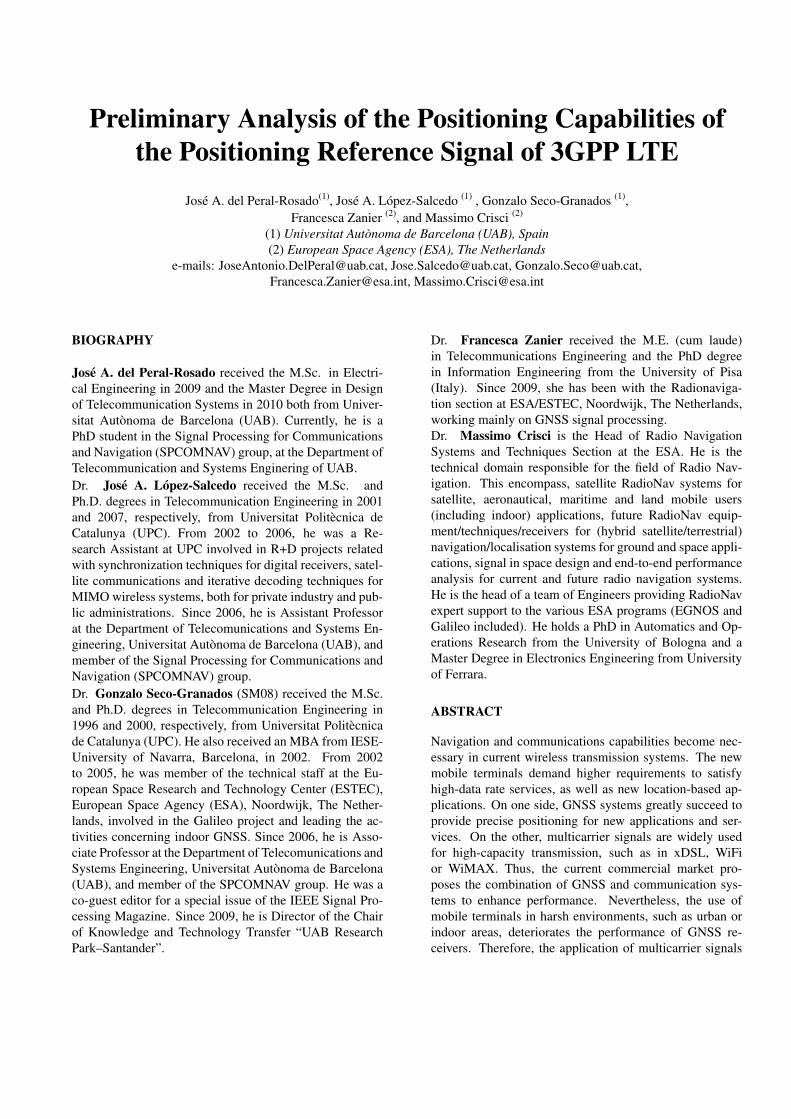
According to the LTE downlink standard, only two kindof waveforms suitable for positioning have been presented:OFDM signal with contiguous pilot subcarriers (i.e. syn-chronization signals), and OFDM signal with distributedpilot subcarriers (i.e. positioning reference signals). Forthese cases, the power is uniformly allocated for all thesubcarriers, but a different power allocation distributioncould be considered. Thus, four different pilot distribu-tions, which are shown in Fig. 10, are used to compute

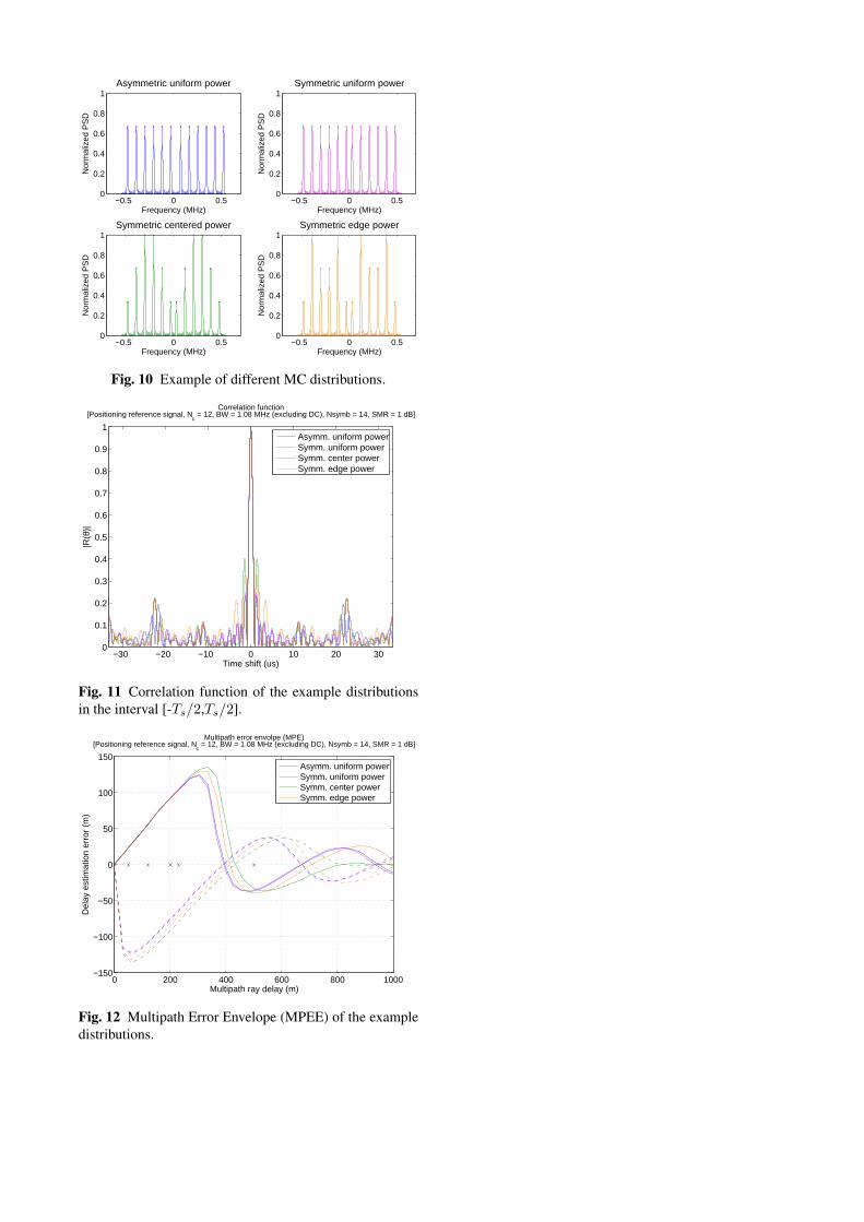
the MPEE. These distributions has been based on the pat-tern of the PRS signal and an advantageous power alloca-tion for positioning. As it can be noticed in Fig. 12, thesymmetry of the pilots slightly decreases the multipath im-pact. However, the power allocation modifies the PSLR ofthe correlation function, which can be seen in Figure 11,and directly increases the maximum delay estimation error.Further study should be conducted in order to evaluate thebenefits of these power distributions on TDE performance.Thus, the flexibility of multicarrier signals may help in afuture on designing an optimum signal waveform able toobtain a good TDE accuracy and multipath resistance.
6. CONCLUSION
A preliminary analysis of the Long Term Evolution (LTE)positioning capabilities is presented in this paper to evalu-ate its potential as NAV-COM system. First, the review ofthe 3GPP LTE standard has highlighted three positioningmodalities: Assisted GNSS, Enhanced Cell-ID, and Ob-served TDoA (OTDoA). Focusing on the LTE multicarrierdownlink signals used for OTDoA, especially the position-ing reference signal (PRS), their assessment has been eval-uated with the computation of the RMSE and the Cramer–Rao bound (CRB) in AWGN channel. In order to obtainthe C/N0 working region, a LTE software simulator hasbeen implemented resulting on a range between 45 and 75dB·Hz. Finally, an artificial two-ray multipath model hasbeen preliminary analysed by means of the multipath er-ror envelope (MPEE). Further research for validation of re-sults, evaluation of 2D position performance and realisticmultipath channel effects is left as future work.
REFERENCES
[1] 3GPP home page. [Online]. Available: http://www.3GPP.org[2] 3GPP TS 36.305, Technical Specification, Stage 2 func-
tional specification of User Equipment (UE) positioning in E-UTRAN (Release 9), 3rd Generation Partnership Project Std.,V9.3.0, (2010-06).
[3] 3GPP TS 36.211, Technical Specification, Physical Chan-nels and Modulation (Release 8), 3rd Generation PartnershipProject Std., V8.6.0, (2009-03).
[4] S. Kay, Fundamentals of Statistical Signal Processing: Esti-mation Theory. Prentice-Hall PTR, 1993–1998.
[5] 3GPP TR 36.942, Technical Specification , Radio Frequency(RF) system scenarios (Release 9), 3rd Generation Partner-ship Project Std., V9.1.0, (2010-09).
[6] R1-092307, “Analysis of UE Subframe Timing OffsetMeasurement Sensitivity to OTDoA Performance,” 3GPP,Alcatel-Lucent, RAN1-57bis, Los Angeles, USA, June 2009.
[7] 3GPP TS 36.101, Technical Specification, User Equipment(UE) radio transmission and reception (Release 9), 3rd Gen-eration Partnership Project Std., V9.8.0, (2011-06).
−30 −20 −10 0 10 20 300
0.2
0.4
0.6
0.8
1
Absolute value of the correlation function[Synchronization signal, N
c = 62, BW = 0.93 MHz (excluding DC), Nsymb = 1]
Time shift (us)
|R(θ
)|
0 100 200 300 400 500 600 700 800 900 1000−200
−100
0
100
200
Multipath ray delay (m)
Del
ay e
stim
atio
n er
ror
(m)
Multipath error envolpe (MPE)
SMR = 1 dBSMR = 3 dBSMR = 6 dBETU channel
Fig. 8 Multipath Error Envelope (MPEE) of the SS signal(0.93 MHz).
−400 −300 −200 −100 0 100 200 300 4000
0.2
0.4
0.6
0.8
1
Absolute value of the correlation function[Positioning reference signal, N
c = 12, BW = 1.08 MHz (excluding DC), Nsymb = 14]
Time shift (us)
|R(θ
)|
0 100 200 300 400 500 600 700 800 900 1000−150
−100
−50
0
50
100
150
Multipath ray delay (m)
Del
ay e
stim
atio
n er
ror
(m)
Multipath error envolpe (MPE)
SMR = 1 dBSMR = 3 dBSMR = 6 dBETU channel
Fig. 9 Multipath Error Envelope (MPEE) of the PRS signal(1.08 MHz).
−0.5 0 0.50
0.2
0.4
0.6
0.8
1
Frequency (MHz)
Nor
mal
ized
PS
DAsymmetric uniform power
−0.5 0 0.50
0.2
0.4
0.6
0.8
1
Frequency (MHz)
Nor
mal
ized
PS
D
Symmetric uniform power
−0.5 0 0.50
0.2
0.4
0.6
0.8
1
Frequency (MHz)
Nor
mal
ized
PS
D
Symmetric centered power
−0.5 0 0.50
0.2
0.4
0.6
0.8
1
Frequency (MHz)
Nor
mal
ized
PS
D
Symmetric edge power
Fig. 10 Example of different MC distributions.
−30 −20 −10 0 10 20 300
0.1
0.2
0.3
0.4
0.5
0.6
0.7
0.8
0.9
1
Time shift (us)
|R(θ
)|
Correlation function[Positioning reference signal, N
c = 12, BW = 1.08 MHz (excluding DC), Nsymb = 14, SMR = 1 dB]
Asymm. uniform powerSymm. uniform powerSymm. center powerSymm. edge power
Fig. 11 Correlation function of the example distributionsin the interval [-Ts/2,Ts/2].
0 200 400 600 800 1000−150
−100
−50
0
50
100
150
Multipath ray delay (m)
Del
ay e
stim
atio
n er
ror
(m)
Multipath error envolpe (MPE)[Positioning reference signal, N
c = 12, BW = 1.08 MHz (excluding DC), Nsymb = 14, SMR = 1 dB]
Asymm. uniform powerSymm. uniform powerSymm. center powerSymm. edge power
Fig. 12 Multipath Error Envelope (MPEE) of the exampledistributions.