precision rail guides - brg-catalogues.com/home xi… · · 2013-07-02lwr rail guides lwre rail...
TRANSCRIPT

Precision rail guides

SKF GroupThe SKF Group is an internationalindustrial corporation owned by SKF Sweden AB. Founded in 1907,the company has some 39 000 em-ployees, 80 manufacturing sites and asales network via its own sales com-panies, distributors and dealerscovering 150 countries around theworld. SKF is the world leader in therolling bearing business.
GeneralSKF Linear MotionSKF Linear Motion belongs to the SKF Group and is specialised in themanufacturing and sales of a widerange of high precision components,units and systems for linear move-ments, providing solutions for guid-ing, driving, actuation and positioningtasks. In addition, SKF Linear Motionalso offers a large assortment of prod-ucts which are in synergy to the linear
motion range and are providingcomplete solutions for applications.SKF Linear Motion comprises 4 product lines with 10 specialisedsales companies in Europe and NorthAmerica; additionally, productavailability and product applicationsupport is provided world-wide by the international sales network of theSKF Group.
A complete range from a single source for all linear motion functions.
Guiding Driving
Actuation Positioning

4
5
9
12
14
20
25
29
33
37
41
42
44
Product review
Product range
Technical information
Rail guides in kit packaging
LWR rail guides
LWRE rail guides
LWRE ACS rail guides with non-slip cage
LWRM/LWRV rail guides
LWRPM/LWRPV rail guides
LWM/LWV rail guides
LWJ/LWS flat rail guides
LZM Mini Slides
GCL Standard Slides

2
SKF precision rail guides
Introduction
As the world’s leading rolling bearingmanufacturer, SKF supplies practical-ly every type of bearing for rotationaland linear motion.
SKF is therefore in a position tomeet almost any customer require-ment both technically and economi-cally.
This catalogue covers the SKFrange of precision rail guides and ac-cessories.
SKF precision rail guides are highlyaccurate products for linear motionand are therefore ideally suited for usein a wide variety of machine tools,machining centres, handling systemsand special machinery as well asmeasuring and testing equipment.
The “Modular Range” has intro-duced a new concept to the market,ensuring the internal interchangeabili-ty of all well-known guidance systemsincluding the high capacity LWRE-type rail guides. This matrix range ofrail guide modules permits the individ-ual selection of rails and rolling ele-ments.
SKF precision rail guides are avail-able in many different designs, sizesand standard lengths, incorporatingball, roller or needle roller assembliesand slide coating. They are suppliedwith the required accessories for at-tachment and sealing.
The use of SKF precision rail guidesfacilitates the construction of econom-ical, clearance-free linear guides ofpractically any type and length, ac-cording to the building block principle.The characteristics of the guides in-clude:– a constant, high degree of running
accuracy– low-friction, stick-slip free operation– high speed of travel– low heat generation– low wear and high reliability– high stiffness– excellent load carrying capacity
If there is a danger of cage-creep(in particular when the guide ismounted vertically), precision railguides of type LWRE-ACS (Anti-Creep System) are an obvious choice,as they will eliminate this problem.
For applications that are charac-terised by high accelerations or shortstrokes of high frequency, SKF railguides with dry sliding coating arerecommended.
These rail guides are also suitablefor machine tool applications wherethe good damping properties of theguides are of greater importance thanthe lower friction of the rolling elementrail guides. For those applicationswhere rail guides are unsuitable, forinstance because of their limited trav-el, SKF can supply alternative formsof linear guidance systems.
All fast-selling precision rail guidesare also available in convenient kitpackaging. This ensures complete de-livery of all single components includ-ing end pieces and screws.
If you would like further details,please contact the SKF applicationengineering department. We will bepleased to provide the required infor-mation without obligation and at nocost, or to prepare a technical pro-posal.
This catalogue brings together allthe basic data which we consider tobe of interest. For additional informa-tion we recommend the SKF technicalhandbook “Linear guide systems”,publication no. 4185, which containssections on the selection, application,operational life, mounting and mainte-nance of SKF precision rail guides.For further specialised advice pleasecontact your nearest SKF sales office.
All information in this catalogue isbased on 2004 design and manufac-turing standards.
Earlier publications, the data inwhich deviates from that given here,are rendered invalid.

3
Product review ................................................................................................. 4
Product rangeModular Range .................................................................................................. 5Other products .................................................................................................. 8
Technical dataAccuracy of rail guides ...................................................................................... 9Grading of rail guides ........................................................................................ 10Accuracy of adjacent parts................................................................................ 11Selection of rail guides ...................................................................................... 11
Rail guides in kit packaging............................................................................ 12
Modular Range rail guidesTablesLWR rail guides with crossed roller and ball assemblies................................... 14LWRE rail guides with crossed roller assemblies .............................................. 20LWRE ACS rail guides with non-slip cage (Anti Creep System) ........................ 25LWRM/LWRV rail guides with needle roller assemblies .................................... 29LWRPM/LWRPV rail guides with dry sliding coating......................................... 33
Other rail guidesTablesLWM/LWV rail guides with needle roller assemblies ......................................... 37LWJ/LWS flat rail guides with needle roller assemblies..................................... 41LZM Mini Slides................................................................................................. 42GCL Standard Slides......................................................................................... 44
Contents

4
SKF precision rail guides
Product review
SKF Modular Range rail guides
LWRPM/PV
LWRM/V
LWRE
LWR with ballassembly
LWR with rollerassembly
Non-slip cage of LWRE ACS
LWRE ACS
5
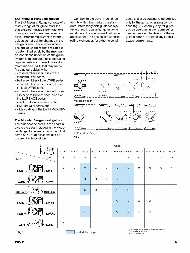
SKF Modular Range rail guides The SKF Modular Range consists of amatrix range of rail guide modulesthat enables individual permutationsof rails and rolling element assem-blies. Different requirements for theguides do not call for changes in thedesign or mechanical environment.The choice of appropriate rail guidesis determined solely by the mechani-cal conditions under which the guidesystem is to operate. These operatingrequirements are covered by six dif-ferent models (fig 1) that may be de-fined as rail guides with:– crossed roller assemblies of the
standard LWR series– ball assemblies of the LWRB series– crossed roller assemblies of the op-
timised LWRE series – crossed roller assemblies with non-
slip cage to prevent cage-creep ofthe LWRE ACS series
– needle roller assemblies of theLWRM/LWRV series and
– slide coating of the LWRPM/LWRPVseries
The Modular Range of rail guidesThe blue shaded areas in the chart in-dicate the sizes included in the Modu-lar Range. Experience has shown thatsome 80 % of applications can becovered by these (fig 2).
fig 2
Market situation
SKF Modular Range
fig 1
TypeSize
A x B
8.5 x 4 12 x 6 18 x 8 31 x 15 44 x 22 58 x 28 71 x 36 83 x 40 110 x 55
1 2 3 2211 4 6 9 12 15 18 24
–
–
–
–
X
–
–
–
–
X
X
X
–
O
–
–
O
–
–
–
X
X
O
O
–
X
X
O
O
–
O
–
O
O
–
O
–
O
O
–
O
–
–
–
–
O
–
–
–
–
= Modular RangeX = available ex-stock in standard lengthsO = available to order– = not available
22 x 11 25 x 12
O––
–
X
–
–
–
O O O – – – –LWRE ACS
OLWRE ACS
Contrary to the current lack of uni-formity within the market, the stan-dard, interchangeable guidance sys-tems of the Modular Range cover al-most the entire spectrum of rail guideapplications. The choice of a specificrolling element or, for extreme condi-
tions, of a slide coating, is determinedonly by the actual operating condi-tions (fig 5). Generally, any rail guidecan be operated in the ‘clamped’ or‘floating’ mode. The design of the railguides does not impose any specialspace requirements.
6
SKF precision rail guides
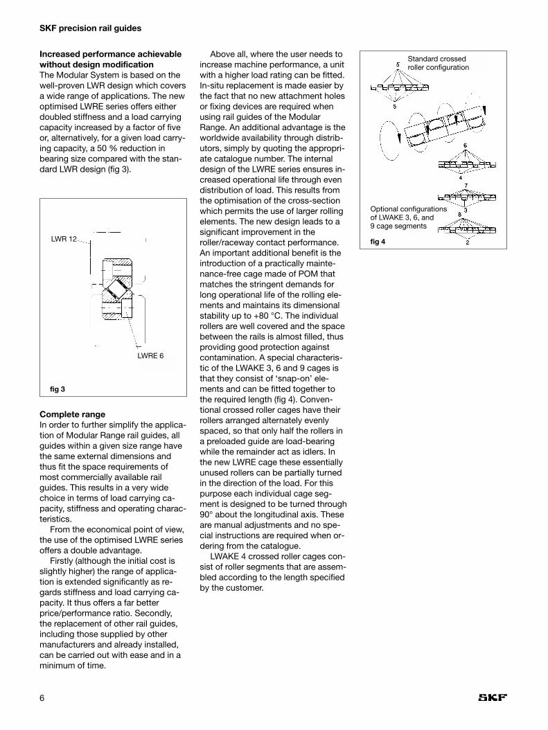
Increased performance achievablewithout design modificationThe Modular System is based on thewell-proven LWR design which coversa wide range of applications. The newoptimised LWRE series offers eitherdoubled stiffness and a load carryingcapacity increased by a factor of fiveor, alternatively, for a given load carry-ing capacity, a 50 % reduction inbearing size compared with the stan-dard LWR design (fig 3).
Above all, where the user needs toincrease machine performance, a unitwith a higher load rating can be fitted.In-situ replacement is made easier bythe fact that no new attachment holesor fixing devices are required whenusing rail guides of the ModularRange. An additional advantage is theworldwide availability through distrib-utors, simply by quoting the appropri-ate catalogue number. The internaldesign of the LWRE series ensures in-creased operational life through evendistribution of load. This results fromthe optimisation of the cross-sectionwhich permits the use of larger rollingelements. The new design leads to asignificant improvement in theroller/raceway contact performance.An important additional benefit is theintroduction of a practically mainte-nance-free cage made of POM thatmatches the stringent demands forlong operational life of the rolling ele-ments and maintains its dimensionalstability up to +80 °C. The individualrollers are well covered and the spacebetween the rails is almost filled, thusproviding good protection againstcontamination. A special characteris-tic of the LWAKE 3, 6 and 9 cages isthat they consist of ‘snap-on’ ele-ments and can be fitted together tothe required length (fig 4). Conven-tional crossed roller cages have theirrollers arranged alternately evenlyspaced, so that only half the rollers ina preloaded guide are load-bearingwhile the remainder act as idlers. Inthe new LWRE cage these essentiallyunused rollers can be partially turnedin the direction of the load. For thispurpose each individual cage seg-ment is designed to be turned through90° about the longitudinal axis. Theseare manual adjustments and no spe-cial instructions are required when or-dering from the catalogue.
LWAKE 4 crossed roller cages con-sist of roller segments that are assem-bled according to the length specifiedby the customer.
fig 3
Complete rangeIn order to further simplify the applica-tion of Modular Range rail guides, allguides within a given size range havethe same external dimensions andthus fit the space requirements ofmost commercially available railguides. This results in a very widechoice in terms of load carrying ca-pacity, stiffness and operating charac-teristics.
From the economical point of view,the use of the optimised LWRE seriesoffers a double advantage.
Firstly (although the initial cost isslightly higher) the range of applica-tion is extended significantly as re-gards stiffness and load carrying ca-pacity. It thus offers a far betterprice/performance ratio. Secondly,the replacement of other rail guides,including those supplied by othermanufacturers and already installed,can be carried out with ease and in aminimum of time.
Standard crossedroller configuration
Optional configurationsof LWAKE 3, 6, and 9 cage segments
LWR 12
LWRE 6
fig 4

7
LWR/LWRB seriesThis basic series of the ModularRange covers a wide variety of railguide applications for limited travel.Where low friction is essential, ballcage assemblies are recommended.If, on the other hand, high load carry-ing capacity is the chief requirement,robust crossed roller assemblies areto be preferred. The LWR series ismanufactured in nine sizes based onrolling element dimensions.
LWRE seriesFor a given load carrying capacity, thedimensions of the LWRE series aresignificantly less than those of thecorresponding member of the LWRseries.Thus, for instance, an LWRE 6 guidewith a cage length of 100 mm has agreater load carrying capacity than astandard LWR 12. The LWR 12 mea-sures 58 x 28 mm whereas the LWRE6 measures only 31 x 15 mm (fig 1).
LWRE ACS seriesAll rails of the LWRE series are alsoavailable with ACS, a special systemto prevent “cage-creep”. These railsare used where cage-creep occursdue to high acceleration, uneven pre-loading or load distribution as well asjerky running or direction-dependentspeeds of travel.
LWRM/LWRV seriesThese guides are used principallywhere high load carrying capacity iscalled for in combination with highstiffness, for instance on grinding ma-chines. This series is fitted with nee-dle roller and cage assemblies con-sisting of two rows of needle rollers atright angles to each other.
LWRPM/LWRPV seriesWhere extremely short strokes of highfrequency occur, this special serieswith slide coating is an essential alter-native to those with rolling element
assemblies. In the case of balls orrollers subjected to high transverseacceleration, pitting of the tracks mayoccur as a result of the unfavourabletribological conditions. Sliding railguides are preferred in such circum-stances.
The coating material is based onPTFE and is bonded on to the unhard-ened LWRPM rail and then ground tothe correct dimension.
This wear-resistant material combi-nation is characterised by its stick-slip-free, vibration-damping runningproperties, at the same time offeringexcellent stiffness and emergencyrunning properties. These guide railsare largely insensitive to contamina-tion, coolants and lubricants.
Materials and precisionThe rails of the Modular Range guidesare manufactured from tool steel 90 MnCrV 8 with a hardness of be-tween 58 and 64 HRC. If required bythe application, the rails can also besupplied in special stainless steel, e.g.X 90 CrMoV 18 in all standard dimen-sions. All rolling elements are madefrom carbon chromium steel 100 Cr 6with a hardness of between 58 and 64 HRC. The parallelism of the race-ways is divided into three classes.Class P10, with a maximum deviationof 10 µm per 1000 mm length, meetsmost of the demands for normal ma-chinery. Where greater precision is re-quired, tolerance classes P5 and P2are also available.
The assortment is complementedby various accessories specially de-signed for the Modular Range of railguides. These include end pieces withor without wipers as well as specialattachment screws.
fig 5
LWRPM/LWRPVSlide coating
LWRM/LWRVNeedle roller
LWR/LWRBBall
LWRCrossed roller
LWRECrossedroller
LWRE ACS

8
SKF precision rail guides
Other productsIn addition to the Modular Range, theselection of SKF products also in-cludes a wide variety of rail guidesand rolling elements.
LWM/LWV rail guides(see table on pages 38-40)LWM/LWV rail guides differ from theLWRM/LWRV guides of the ModularRange only in their external dimen-sions. Their internal geometry is iden-tical and the same needle roller as-semblies are therefore used.
In contrast to LWRM/LWRV (twoseries), the LWM/LWV guides com-prise 6 series up to a size of A x B =80 mm x 50 mm. LWM/LWV railguides are supplied as standard withholes of type 15, namely throughholes with counterbore. If for designreasons it is necessary to screw bothrails from the same side, then one ofthe rails should have holes of type 13,i.e. with thread insert.
LWML rail guides(no table)The LWML rail guide consists of amodified LWM rail guide with the ad-dition of an adjustment wedge. Usedin conjunction with an LWV guide anda needle roller assembly this providesan adjustable guide unit. The inclina-tion of the wedge surface is 1,5 % sothat a displacement of the wedge by 1 mm brings about a 15 µm alterationin the height.
LWML rail guides are supplied asstandard with holes of type 15, i.e.through holes with counterbore. If re-quired holes of type 13, i.e. withthread insert, are also available.
LWML rail guides can be suppliedto tolerance classes P10 and P5.
These guides, as well as the appro-priate needle roller assemblies andend pieces, are made to order.
Because of the many permutationsavailable, each part of an LWML/LWVrail guide must be ordered separately,e.g.:
1 rail LWML 552004001 rail LWM 402004002 rails LWV 402004002 end pieces LWEML 40202 end pieces LWEM 4020
It should also be stated whetherthe holes should comprise right-handor left-hand threads.
LWN/LWO rail guides(no table)LWN/LWO rail guides differ from theLWM/LWV rail guides only in height,width and attachment holes. The in-ternal geometry is identical to that ofthe LWM/LWV guides, i.e. they havethe same load rating.
LWN/LWO rail guides are availablein tolerance classes P10, P5 and P2to order.
LWW/LWZ flat rail guides(no table)LWW/LWZ flat rail guides are used inconjunction with LWR rail guides forincorporation in floating slides.LWW/LWZ flat rail guides and the ap-propriate rolling element assembliesand end pieces are available to order.
LWJ/LWS flat rail guides(no table)LWJ/LWS flat rail guides are used inconjunction with LWRM/LWRV,LWM/LWV or LWN/LWO rail guides asnon-locating linear guides. They areincorporated in floating slides.
LWJ/LWS flat rail guides as well asthe appropriate rolling element as-semblies and end pieces are availableto order.
Special rail guides and recirculatingroller assembliesIn addition to the standard rail guidesincluded in this catalogue, SKF alsomanufactures flat rail guides with re-circulating roller assemblies as well asspecial rail guides to customer draw-ings for such applications as machinetools, handling systems and robotics.
Further information on these spe-cial versions and their availability willbe supplied on request.

9
Technische Hinweise
Precision of rail guidesAll SKF precision rail guides, regard-less of type, are manufactured to thesame tolerances indicated below.
Raceway accuracy In order to meet the different require-ments regarding the precision of linearbearing arrangements, the rails areproduced in three different toleranceclasses. These are classified accord-ing to the parallelism between theraceways and the support surfaces Aand B (fig 6).
P10Tolerance class normal. This meetsthe requirements of general engineer-ing applications. The deviation fromparallelism for a 1000 mm long rail isapproximately 10 µm. See also adja-cent table 1.
P5This satisfies the demands normallymade on the running accuracy for ma-chine tool applications. The deviationfrom parallelism for a 1000 mm longrail is 5 µm maximum. See also adja-cent table 1.
P2Accuracy for the most exacting de-mands. Rails made to this toleranceclass should only be used when theassociated components are made toa correspondingly high degree of pre-cision. Rails to tolerance class P2 willbe manufactured by SKF to specialorder. See also table 1.
If no mention is made of the requi-site accuracy on the order, rails withnormal P10 tolerances will be sup-plied.
Dimensional accuracySKF precision rail guides with limitedtravel are produced to the followingtolerances (figs 7 and 8):
Width A: 0/-0,3mmAbutment heightT = B1 + B2 ± 0,02 mmRail height B: 0/-0,2 mmRail length L: L ≤ 300 ± 0,3
L > 300 ± 0,001 · L [mm]For rails composed of two or more
sections the tolerance for the totallength is ± 2 mm.
SKF precision rail guides for recir-culating roller assemblies are pro-duced to the following tolerances:
Width A: 0/+0,1 mmHeight A: 0/+0,1 mmLength L: 0/+0,002 · L mm
fig 6
Permissible deviation in parallelism between reference planes A and B
Rail length Tolerance classfrom to P10 P5 P2
mm µm
100 2 1 1
100 200 3 2 1
200 300 4 2 1
300 400 5 2 2
400 500 6 3 2
500 600 6 3 2
600 700 7 4 2
700 800 8 4 2
800 900 8 5 2
900 1000 9 5 2
1000 1200 10 6 3
1200 1400 11 6 3
1400 1600 12 7 3
Table 1

10
SKF precision rail guides
Grading Precision rail guides with limited travelare generally mounted in pairs. In or-der to obtain the same assemblyheight T (fig 7), the rails are gradedand supplied in pairs.
This ensures that any two similarrail guides in a system will have thesame height. The grading accuracy isalways within the appropriate toler-ance class for the parallelism.
If two or more rolling element as-semblies are to be mounted immedi-ately behind each other in a rail guide,the rolling elements must have thesame tolerance grade. On request,graded rolling element assembliescan be supplied.
Rails of the same profile for recircu-lating roller assemblies, which are tobe mounted immediately adjacent toeach other or immediately behindeach other should be ordered in grad-ed condition. Depending on theirtype, they will be graded in height orin height and width and delivered as asingle package.
Rail guide sets are always matchedso that it is not necessary to requestthis when ordering.
Tolerance of distance betweenattachment holesThe maximum deviation in the dis-tance between the attachment holesmeasured from centre to centre is ± 0,8 ‰ of the rail length L for one-piece rails (fig 8). Where the rail con-sists of several sections, the toleranceis also ± 0,8 ‰, related to the lengthof the longest section. Rails havingtighter tolerances for the distance be-tween the holes can be supplied onrequest.
Marking of matched setsMatched components are markedwith consecutive numbers as indicat-ed in fig 8a.
fig 7
fig 8 a
fig 8
(=B1+B2)

Accuracy of form of support surfaces
Characteristic Symbol for Permissibledeviation of form
Charac- Tolerance Dimensions Tolerance classteristic zone
P10 P5 P2
Roughness Ra a µm 1,6 0,8 0,2
Perpendicularity ⊥ t1/t2 µm/mm 0,3 0,3 0,3
Parallelism ⁄ ⁄ t3/T4 µm depending on theguide length L (mm)3 2 1 2006 4 2 50010 6 3 1000
11
Accuracy of adjacent componentsAn important criterion for the correctperformance of a rail guide system isthe accuracy of the associated com-ponents. The higher the demands foraccuracy of guidance and for smooth,easy operation, the greater the atten-tion which must be paid to the accu-racy of form and position of the asso-ciated components. Generally thesame accuracy requirements shouldbe applied to these components as tothe rail guides themselves. The adja-cent table shows the values, for eachtolerance class, of the surface rough-ness, perpendicularity and parallelismof the adjacent components.
To assure an even load distributionover the roller length, the maximumdifference in height of the supports fora rail guide should not exceed
∆h = 0,1 · B1
where∆h = maximum height deviation, µmB1 = mean distance between two
rail guides, mm
To obtain good support for the railson the associated components, theattachment holes should be carefullydeburred (figs 9 and 10).
Selection of rail guidesWhen selecting a rail guide, the lengthof travel, load carrying capacity, requi-site life and stiffness are the most de-cisive factors. Other important para-meters include the requisite speed oftravel, lubrication, operating tempera-tures, ease of movement, environ-mental influences and certain designconstraints, for instance whether“clamped” or “floating” guidance isrequired. For additional informationwe recommend the SKF technicalhandbook publication no. 4185.
The selection of the size and lengthof the rolling element assemblies ismainly determined by the required loadcarrying capacity, life and stiffness.
For light, centrally acting loads andmoderate demands for speed of trav-el, it is possible to use practically allthe types of guides listed in this cata-logue. However, technical and eco-nomic reasons often dictate thechoice of the most appropriate modelfor a given application.
The length of a rail guide and of theindividual rails is mainly determinedby the travel as well as the length ofthe rolling element assemblies, whichdepends on the requisite load carry-ing capacity and life.
The following relationships serve asguidelines for determining the lengthof rail guides and rolling element as-semblies:
For a given stroke:
Cage length = stroke, at least
For a given cage length:
Rail length = cage length+ 0,5 x stroke
For a given rail length and stroke, thecage length is is obtained from:
Cage length = Rail length– 0,5 x stroke
fig 9
fig 10

12
SKF precision rail guides
SKF precision rail guides in kit packaging
Rail guides in kit packagingKit packaging is a new service offeredby SKF. Each kit consists of a four-piece rail guide set, 2 cages and 8 end pieces.
Advantages of rail guide kits– all required components are sup-
plied in ready-to-mount sets andcan be ordered via one single ordernumber
– for enhanced ease of mounting, allparts can now be supplied directlyto the machine on site
– cage length easily adjustable – environmentally compatible packag-
ing that can be returned free ofcharge and directed to the recyclingprocess
– most kits available ex stock– also available with ACS for the ef-
fective prevention of cage-creep
Certified in accordance with ISO14001, SKF Linear Motion and the en-tire SKF Group attach great impor-tance to environmental protection.Hence as a matter of course, SKF kit
packagings can be returned free ofcharge and are directed to the recy-cling process. This makes them botha convenient and an environmentally-friendly packaging solution.
LWR 6100 Kit 4915 5440 50 67 LWR 6100 LWAL 6x8LWR 6150 Kit 6744 8160 78 100 LWR 6150 LWAL 6x12LWR 6200 Kit 8441 10880 106 133 LWR 6200 LWAL 6x16LWR 6250 Kit 10045 13600 134 167 LWR 6250 LWAL 6x20LWR 6300 Kit 11955 17000 144 200 LWR 6300 LWAL 6x25LWR 6350 Kit 13422 19720 172 233 LWR 6350 LWAL 6x29LWR 6400 Kit 14846 22440 200 267 LWR 6400 LWAL 6x33including 8 end pieces LWERA 6
Designation Load ratings Stroke Type of rail Type of cagedyn. stat. 4 pieces 2 piecesC C0 min. max.N mm
LWR 3050 Kit 999 1120 26 33 LWR 3050 LWAK 3x7LWR 3075 Kit 1422 1760 36 50 LWR 3075 LWAK 3x11LWR 3100 Kit 1811 2400 46 67 LWR 3100 LWAK 3x15LWR 3125 Kit 2088 2880 66 83 LWR 3125 LWAK 3x18LWR 3150 Kit 2442 3520 76 100 LWR 3150 LWAK 3x22LWR 3175 Kit 2781 4160 86 117 LWR 3175 LWAK 3x26LWR 3200 Kit 3110 4800 96 133 LWR 3200 LWAK 3x30including 8 end pieces LWERA 3
LWR rail guides in kit packaging

13
Designation Load ratings Stroke Type of rail Type of cagedyn. stat. 4 pieces 2 piecesC C0 min. max.N mm
LWRE 3050 Kit 4230 5100 25 33 LWRE 3050 LWAKE 3x6LWRE 3075 Kit 5803 7650 38 50 LWRE 3075 LWAKE 3x9LWRE 3100 Kit 7263 10200 50 67 LWRE 3100 LWAKE 3x12LWRE 3125 Kit 8644 12750 63 83 LWRE 3125 LWAKE 3x15LWRE 3150 Kit 9964 15300 75 100 LWRE 3150 LWAKE 3x18LWRE 3175 Kit 11238 17850 88 117 LWRE 3175 LWAKE 3x21LWRE 3200 Kit 12471 20400 100 133 LWRE 3200 LWAKE 3x24including 8 end pieces LWERE 3
LWRE 4100 Kit 17300 20800 39 67 LWRE 4100 LWAKE 4x10LWRE 4150 Kit 23735 31200 62 100 LWRE 4150 LWAKE 4x15LWRE 4200 Kit 28541 39520 95 133 LWRE 4200 LWAKE 4x19LWRE 4250 Kit 34246 49920 118 167 LWRE 4250 LWAKE 4x24LWRE 4300 Kit 38622 58240 152 200 LWRE 4300 LWAKE 4x28LWRE 4350 Kit 43902 68640 169 233 LWRE 4350 LWAKE 4x33LWRE 4400 Kit 49009 79040 192 267 LWRE 4400 LWAKE 4x38including 8 end pieces LWERE 3
LWRE rail guides in kit packaging
LWRE 6100 Kit 25743 27300 46 67 LWRE 6100 LWAKE 6x7LWRE 6150 Kit 34000 39000 80 100 LWRE 6150 LWAKE 6x10LWRE 6200 Kit 44204 54600 92 133 LWRE 6200 LWAKE 6x14LWRE 6250 Kit 51431 66300 126 167 LWRE 6250 LWAKE 6x17LWRE 6300 Kit 58382 78000 160 200 LWRE 6300 LWAKE 6x20LWRE 6350 Kit 67304 93600 172 233 LWRE 6350 LWAKE 6x24LWRE 6400 Kit 73781 105300 206 267 LWRE 6400 LWAKE 6x27including 8 end pieces LWERE 6
LWRE 6100 ACS - Kit 22826 23400 37 67 LWRE 6100 ACS LWAKE 6 x 6 ACSLWRE 6150 ACS - Kit 31318 35100 71 100 LWRE 6150 ACS LWAKE 6 x 9 ACSLWRE 6200 ACS - Kit 39196 46800 105 133 LWRE 6200 ACS LWAKE 6 x 12 ACSLWRE 6250 ACS - Kit 49056 62400 117 167 LWRE 6250 ACS LWAKE 6 x 16 ACSLWRE 6300 ACS - Kit 56093 74100 151 200 LWRE 6300 ACS LWAKE 6 x 19 ACSLWRE 6350 ACS - Kit 65107 89700 163 233 LWRE 6350 ACS LWAKE 6 x 23 ACSLWRE 6400 ACS - Kit 71640 101400 197 267 LWRE 6400 ACS LWAKE 6 x 26 ACSincluding 8 end pieces LWERE 6
LWRE 4100 ACS - Kit 14536 16640 40 67 LWRE 4100 ACS LWAKE 4 x 8 ACSLWRE 4150 ACS - Kit 19944 24960 79 100 LWRE 4150 ACS LWAKE 4 x 12 ACSLWRE 4200 ACS - Kit 26170 35360 96 133 LWRE 4200 ACS LWAKE 4 x 17 ACSLWRE 4250 ACS - Kit 30859 43680 129 167 LWRE 4250 ACS LWAKE 4 x 21 ACSLWRE 4300 ACS - Kit 36452 54080 152 200 LWRE 4300 ACS LWAKE 4 x 26 ACSLWRE 4350 ACS - Kit 41813 64480 175 233 LWRE 4350 ACS LWAKE 4 x 31 ACSLWRE 4400 ACS - Kit 45964 72800 203 267 LWRE 4400 ACS LWAKE 4 x 35 ACSincluding 8 end pieces LWERE 4
Designation Load ratings Stroke Type of rail Type of cagedyn. stat. 4 pieces 2 piecesC C0 min. maxN mm
LWRE 3050 ACS - Kit 4230 5100 20 33 LWRE 3050 ACS LWAKE 3 x 6 ACSLWRE 3075 ACS - Kit 5294 6800 30 50 LWRE 3075 ACS LWAKE 3 x 6 ACSLWRE 3100 ACS - Kit 6300 8500 45 67 LWRE 3100 ACS LWAKE 3 x 10 ACSLWRE 3125 ACS - Kit 7731 11050 62 83 LWRE 3125 ACS LWAKE 3 x 13 ACSLWRE 3150 ACS - Kit 9090 13600 79 100 LWRE 3150 ACS LWAKE 3 x 16 ACSLWRE 3175 ACS - Kit 9964 15300 94 117 LWRE 3175 ACS LWAKE 3 x 18 ACSLWRE 3200 ACS - Kit 11653 18700 100 133 LWRE 3200 ACS LWAKE 3 x 22 ACSincluding 8 end pieces LWERE 3
LWRE ACS rail guides in kit packaging (supplied to order)
14
SKF precision rail guides
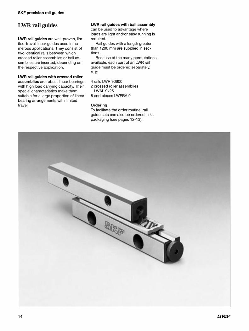
LWR rail guides
LWR rail guides are well-proven, lim-ited-travel linear guides used in nu-merous applications. They consist oftwo identical rails between whichcrossed roller assemblies or ball as-semblies are inserted, depending onthe respective application.
LWR rail guides with crossed rollerassemblies are robust linear bearingswith high load carrying capacity. Theirspecial characteristics make themsuitable for a large proportion of linearbearing arrangements with limitedtravel.
LWR rail guides with ball assemblycan be used to advantage whereloads are light and/or easy running isrequired.
Rail guides with a length greaterthan 1200 mm are supplied in sec-tions.
Because of the many permutationsavailable, each part of an LWR railguide must be ordered separately, e. g:
4 rails LWR 906002 crossed roller assemblies
LWAL 9x258 end pieces LWERA 9
OrderingTo facilitate the order routine, railguide sets can also be ordered in kitpackaging (see pages 12-13).

15
Ball and crossed roller assembliesfor LWR rail guides
Ball assembliesWhere moderate loads are to be sup-ported by a rail guide and greater pri-ority is given to smooth operation andlow friction, the use of ball assembliesis recommended.
LWJK ball assemblies are providedwith a plastic ball-retaining cage.These are available for sizes 1 and 2.
Crossed roller assembliesWhere greater stiffness is required,crossed roller assemblies are recom-mended. Various cage types are avail-able, depending on the size of therollers.
LWAK crossed roller assemblies arefitted as standard for size 3 with aplastic cage to retain the cylindricalrollers.
LWAL crossed roller assemblies areavailable in sizes 6 to 12 with alumini-um cages. They comprise retainedrollers.
End pieces for LWR rail guidesEnd pieces prevent the drift of thecage away from the loaded zone.
LWERA end pieces fulfil these re-quirements in low-load conditionscombined with horizontal mounting.
Attachment screws for LWR rail guidesIn particular in the case of long railguides, heat treatment can lead tothermal expansion which will also in-fluence the distance between the tapholes. Special attachment screwscompensate for this longitudinal ex-pansion.
LWGD special attachment screwscan be used for all rails within theModular Range.
SKF Modular RangeThe LWR rail guides form the basis forthe whole Modular Range system. Allguides with designations commenc-ing LWR... included in this catalogueare interchangeable with each otherwithin a given dimension series. All
external and attachment dimensionscorrespond with those of the LWRseries.LWR rail guides are available in a totalof nine sizes. The “Modular Range”includes sizes 3, 6 and 9 which, ac-cording to experience, cover 80 % ofthe normal market requirements. Toenable prompt delivery from stock,certain standard rail lengths havebeen defined.SKF Modular Range rail guides arespecially highlighted in the tables. Forfurther information, please refer topages 5 to 7.

16
SKF precision rail guides
LWRRail guides
Designation Designation Dimensions:new System Mounting holes End face holes Available lenghts
A B A1 Dw J J1 J2 G G1 N N1 J3 G2 G3 L1)
mm 020 030 040 045 050 060
LWRB 1 LW 0804 8,5 4 3,9 1,6 10 5 1,8 M2 1,65 3 1,4 1,9 M1,6 2
LWRB 2 LW 1206 12 6 5,5 2 15 7,5 2,5 M3 2,55 4,4 2 2,7 M2,5 3
• •
• •
• • •
•
Designation Dimensions:System Mounting holes End face holes Available lenghts
A B A1 Dw J J1 J2 G G1 N N1 J3 G2 G3 L1)
mm 050 075 100 125 150 175 200 225 250
LWR 3 18 8 8,2 3 25 12,5 3,5 M4 3,3 6 3,2 4 M3 6
LWR 6 31 15 13,9 6 50 25 6 M6 5,2 9,5 5,2 7 M5 9
LWR 9 44 22 19,7 9 100 50 9 M8 6,8 10,5 6,2 10 M6 9
LWR 12 58 28 25,9 12 100 50 12 M10 8,5 13,5 8,2 13 M8 12
º• •
•
• •
•
• • •
• •
•
•
º
º
1) Other lengths (LWR 15, 18 and 24) available to special order
LWR 3 - LWR 12 LWRB 1 + 2

SKF Modular Range.Preferred range, prompt deliveryPrompt deliveryAvailable to order
Ball and crossed roller assemblies End pieces Special attachment screws
17
LWJK
LWAK
LWAL
LWERA 1+2
LWGD
Ball and crossed roller assemblies End pieces1) Specialattach-mentscrews
070 075 080 090 100 105 120 135 150 LWJK LWERA LWGD
•
•
•
•
Ball and crossed roller assemblies End pieces1) Specialattach-mentscrews
275 300 350 400 450 500 550 600 650 700 800 900 1000 LWAK LWAL LWERA LWGD
•
•
•
•
•
•
•
•
º ººº• • •
•
• • •
• •
•
º• •
•
º
• •
º
º º º ºº º º
ººººº º
•
•
º•
Example: 4 LWR 3100 or 4 LWR 902002 LWAK 3 x 17 2 LWAL 9x10⁸ LWERA 3 4 LWERA 9
LWERA 3-12
º º º
•º º
•
•
•

18
SKF precision rail guides
Accessories for LWR rail guidesBall and crossed roller assemblies
Designation1) Dimensions Load ratings Appropriatefor 10 rolling elements rail guidedynamic static
Dw U U1 t t1 C C0
mm N
LWJK 1 1,6 3,5 0,5 2,2 1,0 410 580 LWRB 1LWJK 2 2 5 0,75 3,0 1,5 640 720 LWRB 2LWAK 3 3 7,5 1 5 3,5 1 320 1 600 LWR 3LWAL 6 6 14,8 2,7 9 6 5 850 6 800 LWR 6LWAL 9 9 20 4 14 9,4 17 000 18 300 LWR 9LWAL 12 12 25 5 18 12 30 000 30 500 LWR 12
For description and data relating to rolling element assemblies, see page 15
LWJK
LWAK
LWAL

End pieces Special attachment screws
19
Designation Dimensions Appropriate Designation Dimensionsattachment Special
End pieces End pieces screw attachmentwith wiper L L1 screws G1 G2 L4 L5 D d SW2)
mm DIN 963 mm
LWERA 1 – 1 – M 1,6 – – – – – – – –LWERB 1 – 0,5 – M 1,6
LWERA 2 – 1,5 – M 2,5 – – – – – – – –LWERB 2 – 0,5 – M 2,5
LWERA 3 – 2,5 – M 3 LWGD 3 M 3 5 12 3 5 2,3 2,5LWERB 3 – 2 – M 3 DIN 7991– LWERC 3 2 5 M 3
LWGD 4 M 3 5 16 3 5 2,3 2,5(for LWRE 4)
LWERA 6 – 3 – M 5 LWGD 6 M 5 8 20 5 8 3,9 4LWERB 6 – 3 – M 5 DIN 7991– LWERC 6 3 6 M 5 DIN 7991
LWERA 9 – 4 – M 6 LWGD 9 M 6 12 30 6 8,5 4,6 5LWERB 9 – 4 – M 6 DIN 7991– LWERC 9 4 7 M 6 DIN 7991
LWERA 12 – 5 – M 8 LWGD 12 M 8 17 40 8 11,3 6,2 6LWERB 12 – 5 – M 8 DIN 7991– LWERC 12 5 8 M 8 DIN 7991
2) Width across flats of internal hexagon
LWGD
LWERA 1+2
LWERB 3–12
LWERB 1+2 LWERB 1 LWERB 2
LWERC 3–12with wiper
LWERA 3-12
wiper
SWwidth across flats

20
SKF precision rail guides
LWRE rail guides
LWRE rail guides are a logical devel-opment of the proven LWR rail guides.Within the Modular Range system theLWRE rail guides offer an outstandingprice/performance ratio.
Alongside the familiar characteris-tics of the LWR series, the new LWRErail guides offer the advantages of afivefold increase in the load carryingcapacity and a doubling of the stiff-ness, achieved through optimised in-ternal geometry in conjunction withlarger roller diameters.
LWRE rail guides offer a greatly in-creased safety margin, thus a verymuch smaller LWRE rail guide can be
used in a given design space whilemaintaining the same load carryingcapacity as the LWR.
The mounting and attachmentdimensions of the LWRE rail guidesconform to those of all the SKFModular Range rail guides includedin this catalogue.
Rail guides of more than 1200 mmin length should be built up of sec-tions. Because of the many permuta-tions available, each part of an LWRErail guide must be ordered separately,e.g.:4 rails LWRE 62002 crossed roller assemblies
LWAKE 6x134 end pieces LWERE 6
OrderingTo facilitate the order routine, railguide sets can also be ordered in kitpackaging (see pages 12-13).

21
Crossed roller assemblies forLWRE rail guides
LWAKE crossed roller cages consistof individual plastic elements.
In LWAKE 3, 6 and 9 cages, theseelements are assembled using a‘snap in’ technique whereby each el-ement can be rotated manuallythrough an angle of 90°. Thus theload rating and stiffness can be en-hanced by turning the rollers in thedirection of the load.
Dimensional stability of the LWAKEcrossed roller assembly is maintainedup to a temperature of +80°C. Thecage retains the rollers and at thesame time almost fills the free space
between the rails, thus providinggood protection against the ingressof dirt.
LWAKE 4 cages consist of rollersegments which are fitted together tothe customer’s specific length require-ments.
End pieces for LWRE rail guidesEnd pieces prevent the drift of thecage away from the loaded zone.
LWERE end pieces are generallyused for horizontal and vertical appli-cations.
All end pieces are supplied withappropriate fixing screws.
Special attachment screws forLWRE rail guidesFor designations and dimensionsplease refer to the LWR table on page19. The LWGD special attachmentscrews listed in the table may be se-lected to suit each size of LWRE railguide.
Internal geometry of LWR andLWRE rail guidesNormal LWR rail guides utilise onlyabout 40 % of the roller length. Due tothe parallel displacement of the loadaxes, LWR rail guides are prone to aninternal tilting moment on the rollers.This can lead to high edge stressesand hence to a reduction of load car-rying capacity. LWRE rail guides, onthe other hand, utilise the whole rollerlength. Their internal geometry is suchthat no tilting moment can occur andthere are no edge stresses.
At the same time the diameter ofthe rollers has been considerably in-creased (+ 33 %). These features pro-vide the following advantages:– fivefold increase in load carrying ca-
pacity– 100 % increase in stiffness

• • •
•
• •
•
• •
•
•
• • •
22
SKF precision rail guides
LWRE rail guidesLWRE 3 - LWRE 9 / LWRE 2211
1) other lengths available to order
Desig- New Dimensions: Attachment holes End face holes Available lengthsnation desig- System
nationA B A1 Dw J J1 J2 G G1 N N1 J3 G2 G3 L1)
mm 050 075 100 125 150 175 200
LWRE 3 LW 1808 18 8 8,7 4 25 12,5 3,5 M 4 3,3 6 3,2 4 M 3 6
LWRE 4 LW 2512 25 12 12 6,5 25 12,5 5 M 4 3,3 6 3,2 5 M 3 6
LWRE 6 LW 3115 31 15 15,2 8 50 25 6 M 6 5.2 9,5 5,2 6,75 M 5 9
LWRE 9 LW 4422 44 22 21,7 12 100 50 9 M 8 6,8 10,5 6,2 9,75 M 6 9
Desig- New Dimensions: Attachment holes End face holes Available lengthsnation desig- System
nationA B A1 Dw J J1 J2 G G1 N N1 J3 G2 G3 L1)
mm 080 120 160 200
LWRE 2211 LW 2211 22 11 10,7 4 40 20 4,5 M 5 4,3 7,5 4,1 6 M 3 6 º º º º

•
•
•
•
•
•
•
•
•
•
• •
º º º º
º º º º ºº º º º
º ºº
• •
• • •
•
• • º º º
•••
23
Crossed End pieces Specialroller attachmentassemblies screws
225 250 275 300 350 400 450 500 550 600 650 700 800 900 1000 LWAKE LWERE LWGD
•
º•
Ordering example: 4 LWRE 904002 LWAKE 9 x 224 LWERE 9
16 LWGD 9
LWAKE
LWERE 4
• •º º º º
Crossed End pieces Specialroller attachmentassemblies screws
240 280 320 360 400 LWAKE LWERE LWGD
º
LWERE 3, 6, 9
LWAKE
LWGD
Crossed roller assemblies End pieces Special attachment screws
SKF Modular RangePreferred range, prompt deliveryPrompt deliveryTo special order

24
SKF precision rail guides
Accessories for LWRE rail guides
Crossed roller assemblies
LWAKE 3, 6, 9
For description and data on crossed roller assemblies, please see page 21
Designation Dimensions Load ratings Rail guide for 10 needle rollers designationper rowdynamic static
Dw t t1 t2 C C0
mm N
LWAKE 3 4 6,25 2,65 3,6 6 300 8 500 LWRE 3, LWRE 2211
LWAKE 4 6,5 8 4,3 4,3 17 300 20 800 LWRE 4
LWAKE 6 8 11 5 6 34 000 39 000 LWRE 6
LWAKE 9 12 16 7,35 8,65 78 000 78 000 LWRE 9
End pieces Special attachment screws
LWGD
Designation Dimensions Appropriate Rail attachment guide
without with screw designationwiper wiper L L1
mm DIN 7991
LWERE 3 2 M 3 LWRE 3, LWRE 2211
LWEREC 3 4 M 3 LWRE 3, LWRE 2211
LWERE 4 4 M 3 (DIN 84) LWRE 4
LWERE 6 3 M 5 LWRE 6
LWEREC 6 5 M 5 LWRE 6
LWERE 9 3 M 6 LWRE 9
LWEREC 9 6 M 6 LWRE 9
for designation and dimensionssee page 19LWERE 3, 6, 9 LWEREC 3, 6, 9
wiper
LWAKE 4
LWERE 4

Axi
al d
isp
lace
men
t [m
m]
Special cage of size 3 with ACSStandard crossed roller cage of size 3
25
LWRE ACS rail guides with non-slip cage (Anti Creep System)
aged cages are a thing of the past.Moreover, the exchange of guides andthe resultant need for readjusting themachine or installation are eliminated.
LWRE ACS rail guides are equivalent to LWRE rail guides, de-signed for use in non-slip LWAKE cages.
The non-slip effect is achievedthrough a patented control gear at-tached to the cage which is in meshbetween the LWRE ACS rails duringoperation, thus retaining the cage in itsdefined position.
The external dimensions of LWREACS rail guides are identical withthose of LWRE rail guides. The non-slip guide has been integrated in theexisting design. Thus, sizes LWRE 3ACS, LWRE 6 ACS and LWRE 9 ACSfit into the Modular Range system.Sizes LWRE 4 ACS and LWRE 2211ACS are available in addition. Split railguides, rails of tolerance class P2 orP5 or protruding cages can be sup-plied upon request.
Advantages – ACS eliminates “cage-creep”– Increased accuracy thanks to de-
fined positioning of cage– Easily interchangeable with stan-
dard precision rails– Identical size thanks to integral de-
sign– Suitable for high acceleration, verti-
cal mounting and uneven load distri-bution
– Less downtime and lower mainte-nance requirements
“Cage-creep” test results
Many users are familiar with “cage-creep” in conventional precision railguides. This effect occurs as a resultof high acceleration and uneven pre-loading or load distribution. Thanks toa new design conceived by SKF Li-nearsysteme GmbH, this drift of thecage away from its intended positionis eliminated through a sophisticated“Anti Creep System”, in short ACS.
Precision rail guides with ACS in-crease the reliability of installationsand lead to extended operating peri-ods of the linear guides. Thus, dam-
Distance travelled [km]

26
LWRE ACS rail guides can be de-signed for specified or maximumtravel of the rail guide system. Forsystems with specified travel, thelength of the stroke is quoted after thesuffix ACS. LWAKE ACS cages mustonly be operated over the specifiedstroke length.
A rail guide with maximum travel isprepared for the use of ACS over itsentire length. This may be required formounting, maintenance or dismount-ing purposes. When placing an order,this design is specified by the suffixACS, without a stroke, directly afterthe LWRE rail guide designation.
SKF precision rail guides
Ordering designation forLWRE ACS rail guides:
LWRE ACS rail guide for maximumtravel of the rail system (see fig 11A):
LWRE rail ACS e.g. LWRE 6200 ACS
LWRE ACS rail guides for specifiedtravel of the rail system (see fig 11B):
LWRE rail ACS stroke (mm)e.g. stroke: 100 mm (cage travel: 50 mm)LWRE 6200 ACS 100 mm
Because of the many permutationsavailable, all parts of LWRE ACS railguides are usually ordered separately,e.g.:
Maximum travel:4 rails2 crossed roller cages8 end pieces
e.g.:LWRE 6200 ACS LWAKE 6x12 ACS (147,3 mm)LWERE 6(see fig 11A)
Specified travel:4 rails2 crossed roller cages8 end pieces
e.g.:LWRE 6200 ACS 100 mmLWAKE 6x12 ACS (147,3 mm)LWERE 6(see fig 11B)
OrderingTo facilitate the order routine, railguide sets can also be ordered in kitpackaging (see pages 12 – 13).
LWRE ACS rail guides for “maximum travel” stroke
LWRE ACS rail guides for “specified travel” stroke
fig 11A
fig 11B
Stroke
Stroke

27
Crossed roller assemblies for LWREACS rail guides
Compared to LWAKE cages, LWAKEACS crossed roller cages incorporatean additional control gear located atthe centre of the cage. The load carry-ing capacity of LWAKE ACS cages isidentical with that of LWAKE standardcages, provided that they comprisean identical number of rollers. Howev-er, it has to be taken into considera-tion that, due to their additional con-trol gear, LWAKE ACS cages arelonger than the corresponding LWAKEcages, even if the number of rollers isidentical. Protruding cages should beused only after consultation with SKF.
Ordering designation for LWAKE ACS cages:
LWAKE ACS cages should be orderedas follows:LWAKE size x number of rollers ACSFor instance, an LWAKE 6 cage with12 rollers and ACS control gear hasthe designation LWAKE 6x12 ACS (147,3 mm).
End pieces for LWRE ACS rail guides
As a rule, end pieces must not beused as a mechanical stroke limitationof the guidance system, as this canresult in cage damage. End piecescan be used as a protection againstexternal influences.
Special attachment screws for LWRE ACS rail guides
For designation and dimensions,please refer to LWR, page 19. The list-ed special attachment screws oftype LWGD can also be used formounting LWRE ACS rail guides, iftheir respective size is taken into con-sideration.
Design and mounting of LWRE ACS rail guides
Mounting of LWRE ACS rail guidesproceeds to the same rules as mount-ing of SKF standard precision rails. In
addition, it is essential to observe thatthe ACS control gear is constantlykept in mesh between the rails duringoperation. Furthermore, the cagemust never be subjected to direct orindirect external axial loads. The ACScontrol gear must not be damagedduring mounting, e.g. through the in-sertion of the ACS cage between therails against an end stop, or tilting ortwisting of two adjacent rails.
Protection and lubrication of LWRE ACS rail guides
In order to ensure the impeccable op-eration of the Anti Creep System, itshould be protected against contami-nation and relubricated with moderatequantities of SKF standard grease.Any “blocking” or “gumming” of theelement must be ruled out.

28
SKF precision rail guides
Accessories forLWRE ACS rail guides
Crossed roller assemblies
LWAKE 3, 6, 9 ACS
For description and data on crossed roller units, please see pages 21, 24 and 27.
Designation Dimensions Load ratings Rail guide for 10 needle rollers designationper rowdynamic static
Dw t t3 C C0
mm N
LWAKE 3 ACS*) 4 6,25 9 6 300 8 500 LWRE 3 ACS, LWRE 2211 ACS
LWAKE 4 ACS 6,5 8 17 17 300 20 800 LWRE 4 ACS
LWAKE 6 ACS 8 11 15,3 34 000 39 000 LWRE 6 ACS
LWAKE 9 ACS 12 16 22 78 000 78 000 LWRE 9 ACS
End pieces Special attachment screws
LWGD
For designation and dimensions please see LWR, page 19.
LWAKE 4 ACS
n = number of rollers
*) For compact applications, SKF can supply cage LWAKE 3x6 ACS-C with l = 40 mm.
For designation and dimensions please see LWRE, page 24.

29
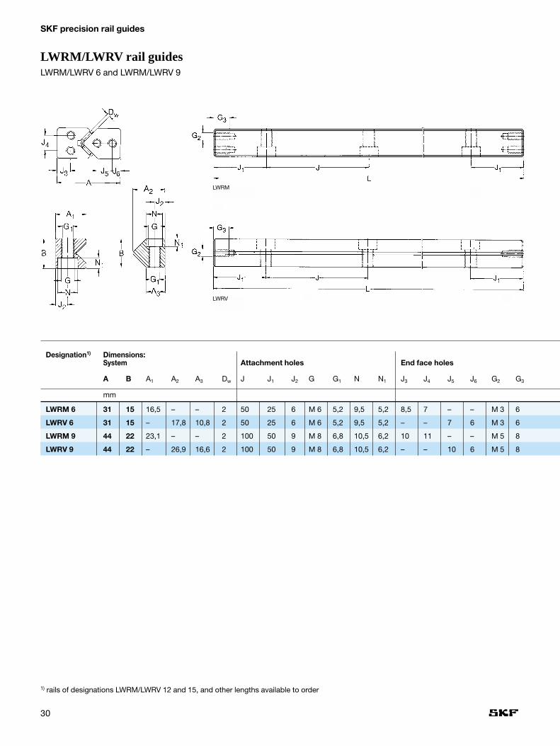
LWRM/LWRV rail guides
LWRM/LWRV rail guides offer guid-ance systems with high load carryingcapacity and maximum stiffness.
Needle roller assemblies forLWRM/LWRV rail guides
LWHW needle roller assemblieshave aluminium cages with retainedneedle rollers. They are available forsize 6 and 9 units.
When ordering, the appropriatecage length in mm should be statedafter the cage designation, e.g.:LWHW 10x225.
End pieces for LWRM/LWRV rail guidesEnd pieces serve to prevent the driftof the cage away from the loadedzone.
LWEARM and LWEARV end piecesfeature a plastic wiper with a sealinglip that keeps the raceways free fromcontamination. All end pieces aresupplied with the appropriate attach-ment screws.
The mounting and attachment di-mensions of LWRM/LWRV railguides conform to those of all theSKF Modular Range rail guides in-cluded in this catalogue.
Because of the many permutationsavailable, each part of anLWRM/LWRV rail guide must be or-dered separately, e.g.:
2 rails LWRM 904002 rails LWRV 904002 needle roller assemblies
LWHW 15x3582 end pieces LWEAM 9
30
SKF precision rail guides
Designation1) Dimensions:System Attachment holes End face holes
A B A1 A2 A3 Dw J J1 J2 G G1 N N1 J3 J4 J5 J6 G2 G3
mm
LWRM 6 31 15 16,5 – – 2 50 25 6 M 6 5,2 9,5 5,2 8,5 7 – – M 3 6
LWRV 6 31 15 – 17,8 10,8 2 50 25 6 M 6 5,2 9,5 5,2 – – 7 6 M 3 6
LWRM 9 44 22 23,1 – – 2 100 50 9 M 8 6,8 10,5 6,2 10 11 – – M 5 8
LWRV 9 44 22 – 26,9 16,6 2 100 50 9 M 8 6,8 10,5 6,2 – – 10 6 M 5 8
LWRM/LWRV rail guidesLWRM/LWRV 6 and LWRM/LWRV 9
1) rails of designations LWRM/LWRV 12 and 15, and other lengths available to order
LWRM
LWRV

Needle roller assemblies End pieces Special attachment screw
31
Available lengths Needle End pieces Specialroller attachm.assemblies screws
L1)
100 150 200 250 300 350 400 500 600 700 800 900 1000 LWHW LWEARM LWEARV LWGD
•
•
•
•
•
•
•
•
ºº
ºº
ºººº
ººº º
ººº
ººº
•
º•
Ordering example: 2 LWRM 906002 LWRV 906002 LWHW 15 x 4504 LWEARM 9
–
–
–
–
•
•
•
•
LWHW aluminiumLWEARVwith wiper
wiper
LWEARMwith wiper
LWGD
ººººººº º º º º º
ºº
ºº
º ºº º
wiper
SKF Modular RangePreferred range, prompt deliveryPrompt deliveryTo special order

32
SKF precision rail guides
Accessories for LWRM/LWRV rail guides
Needle roller assemblies
For description and data on needle roller assemblies, please see page 29
Designation Dimensions Load ratings Rail guidefor 10 needle rollers designationper rowdynamic static
Dw Lw t t1 t2 C C0
mm N
LWHV 10 2 4,8 10 3,75 2,7 10 400 25 500 LWRM 6/LWRV 6
LWHW 10 2 4,8 10 3,75 2,7 10 400 25 500 LWRM 6/LWRV 6
LWHV 15 2 7,8 15 3,75 2,7 16 300 45 000 LWRM 9/LWRV 9
LWHW 15 2 7,8 15 4,5 3,4 16 300 45 000 LWRM 9/LWRV 9
End pieces Special attachment screw
LWGD
Designation Dimensions Appropriate Rail attachment guide
without with screws designationwiper wiper L L1
mm
LWERM 6 4 M 3 DIN 84 LWRM 6
LWERV 6 4 M 3 DIN 84 LWRV 6
LWEARM 6 6 M 3 DIN 84 LWRM 6
LWEARV 6 6 M 3 DIN 84 LWRV 6
LWERM 9 6,3 M 5 DIN 84 LWRM 9
LWERV 9 6,3 M 5 DIN 84 LWRV 9
LWEARM 9 8,3 M 5 DIN 84 LWRM 9
LWEARV 9 8,3 M 5 DIN 84 LWRV 9
for designation and dimensionssee page 19
LWERM
wiper wiper
LWEARM
LWERV
LWEARV
LWHV plastics LWHW aluminium

33
LWRPM/LWRPV rail guidesLWRPM/LWRPV rail guides are lin-ear guides for limited travel, fitted withTurcite-B®1) slide coating.
Based on PTFE, this material isself-lubricating and offers excellentsliding properties.
The coating is bonded to the non-hardened LWRPM rail and subse-quently ground to size. The LWRPVrail is hardened and ground. In orderto avoid damage to the sliding surfaceof the LWRPM rail, the leading edgesof the LWRPV rails are slightly round-ed. Otherwise, the dimensions ofthese rails are the same as those ofthe LWRV series.
LWRPM/LWRPV rail guides shouldbe used where rail guides with rollingelement assemblies are unsuitabledue to external influences.
Such applications include thosesubjected to high transverse acceler-ation that may cause indentation ofthe rolling elements in the raceways,or where extremely short strokes arerequired. The unfavourable tribolo-gical conditions produced by suchoperation would give rise to race-waypitting in a rolling element rail guide.
The mounting and attachment di-mensions of the LWRPM/LWRPVrail guides conform to those of allthe SKF Modular Range rail guidesincluded in this catalogue.
LWRPM/LWRPV rail guides arecharacterised by:– stick-slip-free operation– smooth running– good emergency running properties– low wear and high reliability– insensitivity to contamination– excellent vibration damping
properties
When ordering, the individual compo-nents of the rail guides must bespecified separately, e.g.:
2 rails LWRPM 63002 rails LWRPV 6300
1) Turcite-B® is a registered trademark of Busak & Shamban GmbH

34
SKF precision rail guides
LWRPM/LWRPV rail guidesLWRPM/LWRPV 3 – LWRPM/LWRPV 9
Designation1) Dimensions:System Attachment holes
A B A1 A2 A3 J J1 J2 G G1 N N1
mm
LWRPM 3 18 8 9,5 – – 25 12,5 3,5 M 4 3,3 6 3,2
LWRPV 3 18 8 – 9,6 6,45 25 12,5 3,5 M 4 3,3 6 3,2
LWRPM 6 31 15 16,6 – – 50 25 6 M 6 5,2 9,5 5,2
LWRPV 6 31 15 – 17,8 10,8 50 25 6 M 6 5,2 9,5 5,2
LWRPM 9 44 22 23,1 – – 100 50 9 M 8 6,8 10,5 6,2
LWRPV 9 44 22 – 26,9 16,6 100 50 9 M 8 6,8 10,5 6,2
1) sizes LWRPM/LWRPV 12 and LWRPM/LWRPV 15, also other rail lengths are available to order.
LWRPM
LWRPV
35
SpecialAvailable lengths attach-
mentL1) screws
050 075 100 125 150 175 200 225 250 275 300 350 400 450 500 550 600 650 700 800 900 1000 LWGD
ºº
ºº
º ººº
º º º º º ººº º º ºº º º º
ºººº
ººº
•
•
•
•
•
•
•
º•
Ordering example: 2 LWRPM 64002 LWRPV 6300
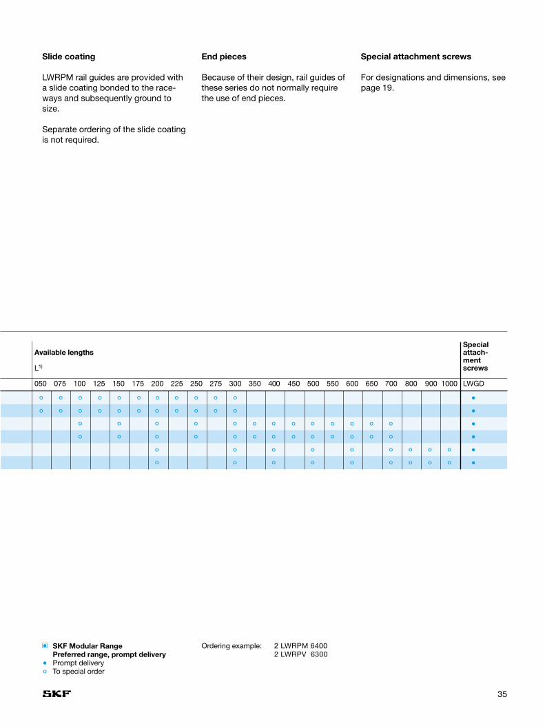
Slide coating
LWRPM rail guides are provided witha slide coating bonded to the race-ways and subsequently ground tosize.
Separate ordering of the slide coatingis not required.
End pieces
Because of their design, rail guides ofthese series do not normally requirethe use of end pieces.
Special attachment screws
For designations and dimensions, seepage 19.
ºº
ºº
ºººº
ºº
ºººº
ºº
ºººººº
ºº
ºººº
ºººº
ºººº
SKF Modular RangePreferred range, prompt deliveryPrompt deliveryTo special order

36
SKF precision rail guides
Accessories for LWRPM/LWRPV rail guidesSlide coating
Designation1) Dimensions Load carrying Rail capacity2) guide
designationRail guide H C
mm N
LWRPM 3 0,7 300/100 mm LWRPV 3
LWRPM 6 1,7 700/100 mm LWRPV 6
LWRPM 9 1,7 1200/100 mm LWRPV 9
1) The slide coating is an integral part of the LWRPM rail and does not have to be ordered separately.2) for a surface loading of approx. 1 N/mm2
(momentary loads of up to 6 N/mm2 are permissible).
End pieces
LWRPM/LWRPV rail guides, by virtue of their design, do not normally require end pieces.
For this reason, tapped holes on the end faces are also unnecessary.
However, for production reasons, LWRPV rail guides will in certain cases be supplied with end face holes.
Special attachment screwsSee page 19 for designations and dimensions.
LWGD
37
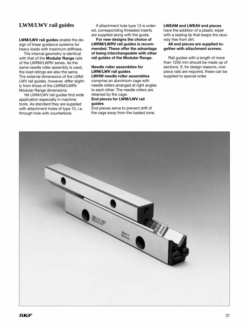
LWM/LWV rail guides
LWM/LWV rail guides enable the de-sign of linear guidance systems forheavy loads with maximum stiffness.
The internal geometry is identicalwith that of the Modular Range railsof the LWRM/LWRV series. As thesame needle roller assembly is used,the load ratings are also the same.The external dimensions of the LWM/LWV rail guides, however, differ slight-ly from those of the LWRM/LWRVModular Range dimensions.
Yet LWM/LWV rail guides find wideapplication especially in machinetools. As standard they are suppliedwith attachment holes of type 15, i.e.through hole with counterbore.
If attachment hole type 13 is order-ed, corresponding threaded insertsare supplied along with the guide.
For new designs the choice ofLWRM/LWRV rail guides is recom-mended. These offer the advantageof being interchangeable with otherrail guides of the Modular Range.
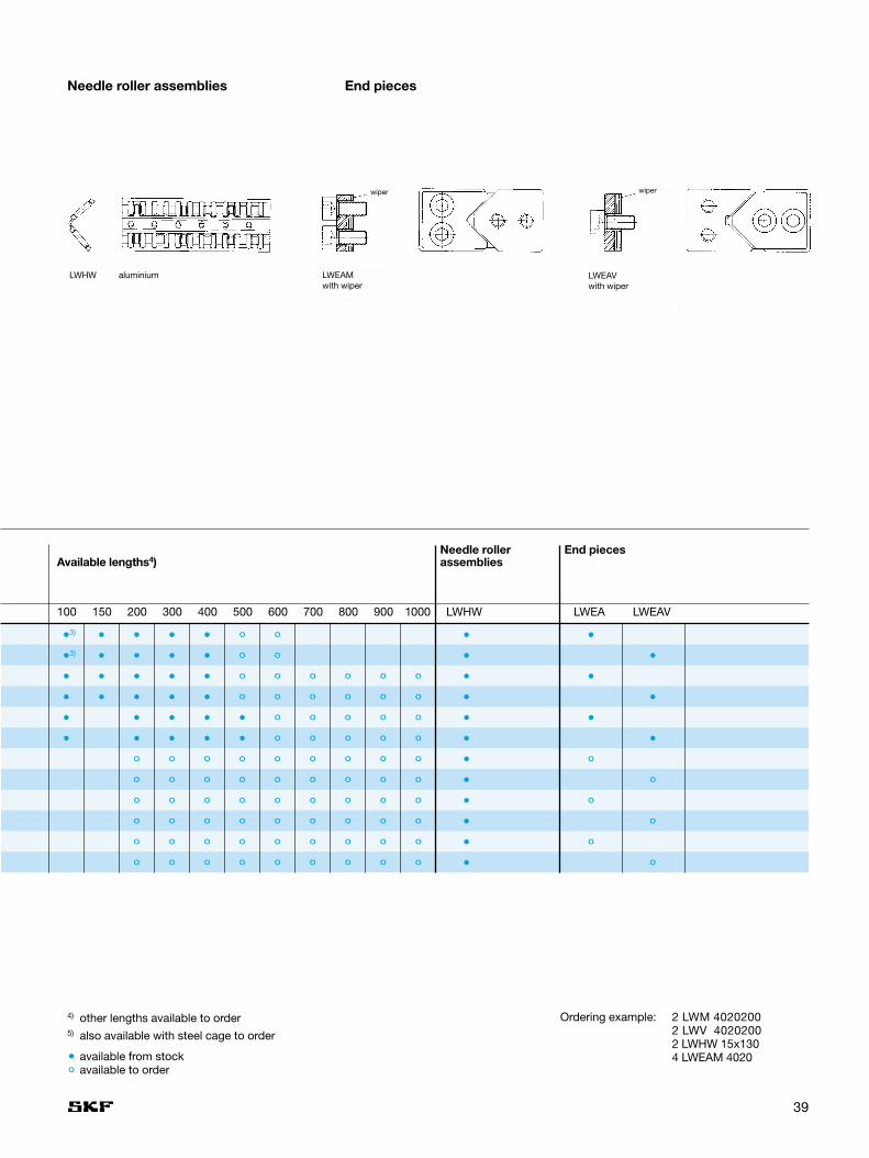
Needle roller assemblies forLWM/LWV rail guidesLWHW needle roller assembliescomprise an aluminium cage withneedle rollers arranged at right anglesto each other. The needle rollers areretained by the cage.End pieces for LWM/LWV railguidesEnd pieces serve to prevent drift ofthe cage away from the loaded zone.
LWEAM and LWEAV end pieceshave the addition of a plastic wiperwith a sealing lip that keeps the race-way free from dirt.
All end pieces are supplied to-gether with attachment screws.
Rail guides with a length of morethan 1200 mm should be made up ofsections. If, for design reasons, one-piece rails are required, these can besupplied to special order.

38
SKF precision rail guides
LWM/LWV rail guidesLWM/LWV 3015 – LWM/LWV 8050
Locktyp 15
Locktyp 15
Locktyp 13 Locktyp 13
LMW rail
LWV rail
Designation Dimensions:System Attachment holes End face holes
A B A1 A2 A3 Dw J1) J1 min2) J2 G N N1 N2 J3 J4 J5 J6 G1 G2
mm
LWM 3015 30 15 16 – – 2 40 15 5,5 M 4 8,5 4,5 5,25 8 7 – – M 3 6
LWV 3015 30 15 – 17,2 10,5 2 40 15 5,5 M 4 8,5 4,5 5,25 – – 7 5,5 M 3 6
LWM 4020 40 20 22,3 – – 2 80 15 7,5 M 6 11,5 6,8 7,5 10 11 – – M 5 7
LWV 4020 40 20 – 22 13,5 2 80 15 7,5 M 6 11,5 6,8 7,5 – – 10,5 5,5 M 5 7
LWM 5025 50 25 28 – – 2 80 20 10 M 6 11,5 6,8 7,5 12 13 – – M 6 8
LWV 5025 50 25 – 28 17 2 80 20 10 M 6 11,5 6,8 7,5 – – 13 7 M 6 8
LWM 6035 60 35 36 – – 2,5 100 20 11 M 8 15 9 10 14 20 – – M 6 8
LWV 6035 60 35 – 36 20 2,5 100 20 11 M 8 15 9 10 – – 18 8 M 6 8
LWM 7040 70 40 40 – – 3 100 20 13 M 10 18,5 11 12,5 16 20 – – M 6 8
LWV 7040 70 40 – 42 24 3 100 20 13 M 10 18,5 11 12,5 – – 20 10 M 6 8
LWM 8050 80 50 45 – – 3,5 100 20 14 M 12 20 13 14 20 30 – – M 6 8
LWV 8050 80 50 – 48,5 26 3,5 100 20 14 M 12 20 13 14 – – 25 10 M 6 8
1) for lengths L < J + 2 · J1 min, J = 50 mm (except for LWM/LWV 3015)2) J1 depends upon the rail length and is of the same size at each end of the rail
J1 = L – ∑ J2
3) J = 35 mm
39
Needle roller End piecesAvailable lengths4) assemblies
100 150 200 300 400 500 600 700 800 900 1000 LWHW LWEA LWEAV
•
•
•
•
•
•
•
•
•
•
LWHW aluminium LWEAMwith wiper
wiper wiper
LWEAVwith wiper
º•
• • •
•
•
•
•
•
•
•
•
•
•
•
•
•
3)
3)
ºººººº
•
•
•
•
•
•
ºººººº
•
•
•
•
•
•
•
•
ºººººº
ºººººº
º ºººººººººººº
ºººººººººº
ºººººººººº
ºººººººººº
ºººººººººº
ººº
•
•
•
º
•
•
•
º
º
º
º
º
•
•
Needle roller assemblies End pieces
available from stockavailable to order
Ordering example: 2 LWM 40202002 LWV 40202002 LWHW 15x1304 LWEAM 4020
4) other lengths available to order5) also available with steel cage to order

40
SKF precision rail guides
Accessories for LWM/LWV rail guidesNeedle roller assemblies
For description and data on crossed roller assemblies, please see page 37.
Designation Dimensions Load ratings Railfor 10 needle rollers guide designationper row
Dw Lw U t t1 dynamic staticC C0
mm N
LWHW 10 2 4,8 10 3,75 2,7 10 400 25 500 LWM/LWV 3015
LWHV 15 2 7,8 15 3,75 2,7 16 300 45 000 LWM/LWV 4020 + 5025
LWHW 15 2 7,8 15 4,5 3,4 16 300 45 000 LWM/LWV 4020 + 5025
LWHV 20 2,5 11,8 20 5 3,7 32 000 88 000 LWM/LWV 6035
LWHW 20 2,5 11,8 20 5,5 4,2 32 000 88 000 LWM/LWV 6035
LWHW 25 3 15,8 25 6 4,4 52 000 143 000 LWM/LWV 7040
LWHW 30 3,5 20 30 7 5,2 76 500 212 000 LWM/LWV 8050
End pieces
wiper
LWEAM LWEV LWEAV
wiper
Designation Dimensions Appropriateattachment
without with screwswiper wiper L L1
mm
LWEM 3015 4 M 3 DIN 84
LWEV 3015 4 M 3 DIN 84
LWEAM 3015 6 M 3 DIN 84
LWEAV 3015 6 M 3 DIN 84
LWEM 4020 6,3 M 5 DIN 84
LWEV 4020 6,3 M 5 DIN 84
LWEAM 4020 8,3 M 5 DIN 84
LWEAV 4020 8,3 M 5 DIN 84
LWEM/LWEV 5025 to 8050 6,9 M 6 DIN 84
LWEAM/LWEAV 5025 to 8050 8,9 M 6 DIN 84
LWHV plastics LWHW aluminium
LWEM
41
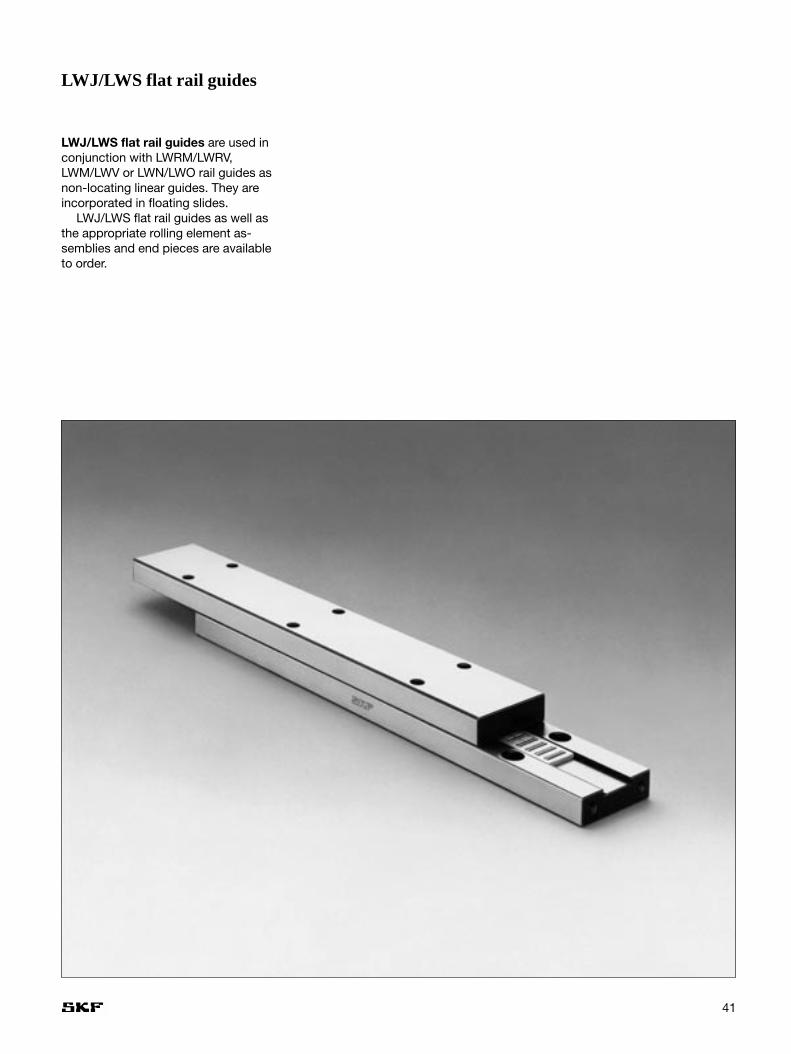
LWJ/LWS flat rail guides
LWJ/LWS flat rail guides are used inconjunction with LWRM/LWRV,LWM/LWV or LWN/LWO rail guides asnon-locating linear guides. They areincorporated in floating slides.
LWJ/LWS flat rail guides as well asthe appropriate rolling element as-semblies and end pieces are availableto order.

42
SKF precision rail guides
LZM Miniature slide
With the new LZM Miniature Slideproduct range SKF Linear Motion &Precision Technologies offers the ide-al solution for linear motion applica-tions for short strokes and compactboundary dimensions. The use ofminiature slides has increased inmedical applications, measurementtechnologies and micro mechanics & assembly.
The different LZM Miniature Slidecomponents meet the highest preci-sion standards. LZM Miniature Slidesfeature high running accuracy andsmooth motion.
The LZM Miniature Slides are man-ufactured with all stainless steel com-ponents. Optimized hardness enables
long endurance life and high perfor-mance within compact boundary di-mensions.
The new LZM Miniature Slides havebeen designed to ensure high systemstiffness and precision guidance.
Running accuracies of 2 µm over astroke of 100 mm are attainable de-pending on the particular application.Ease of installation is another advan-tage of the LZM Miniature Slides. Un-like cross roller systems using 4 railsand cages to be assembled on theproduction floor, the LZM slide pro-vides a complete slide that can simplybe bolted into place without the useof precision devices to set preload.
Every application provides newchallenges for the modern designer.SKF will modify existing designs tomeet your specific technical require-ments.
Applications:• Pneumatics• Semi conductor manufacturing• Medical• Micro- and electronics assembly• Measurement applications• Fiber optics
Advantages:• Compact design• High carrying capacity• Very good running accuracy• Smooth running• High stiffness• Easy assembly

43
Miniatur slide unit Standard Size Length (L)Order example: LZM HS 9 - 32
LZM Miniature slide
Type W W2 W3 L2 M1 x depth d3 x d2 x h H H1 M2 F
mm
LZM HS 7 17 12 7 8 M2 x 2,5 2,5 x 4,5 x 2,5 8 2,35 M3 15
LZM HS 9 20 15 9 13 M3 x 3 3,5 x 6 x 3,5 10 3,55 M4 20
LZM HS 12 27 20 12 15 M3 x 3,5 3,5 x 6 x 4,5 13 4,7 M4 25
LZM HS 15 32 25 15 20 M3 x 4 3,5 x 6 x 4,5 16 6 M4 40
Type L L4 E L1 max. Stroke Number of holes C C0 Ma/Mb McCarriage Rail
mm N Nm
LZM HS 7 26 29 5,5 5 24 6 2 1000 1700 3,5 6
34 37 9,5 5 34 8 2 1100 2100 5,5 7
50 53 10 5 50 12 3 1500 3100 12 10
66 69 10,5 5 66 16 4 1800 4100 21 14
LZM HS 9 32 35 8 9,5 28 4 2 1600 2700 7 12
42 45 11 8 40 6 2 1900 3400 11 15
55 58 7,5 8 54 8 3 2300 4300 18 19
81 84 10,5 8 78 12 4 3000 6500 43 29
94 97 7 8 92 14 5 3300 7400 57 33
LZM HS 12 37 40 6 11 32 4 2 2500 3800 11 21
51 54 13 10,5 47 6 2 3100 5300 22 28
66 69 8 10,5 62 8 3 3600 6700 36 36
96 99 10,5 10,5 95 12 4 4700 9700 76 52
126 129 13 10,5 122 16 6 5700 12600 131 68
LZM HS 15 52 56 6 12,5 50 4 2 3800 6200 25 42
85 89 22,5 12,5 80 8 2 5400 10400 73 70
105 109 12,5 12,5 102 10 3 6200 12500 106 84
165 169 22,5 12,5 162 16 4 8400 19500 264 131

44
SKF precision rail guides
Standard slidesDesign and characteristicfeatures
GeneralThe range of slides shown in this cata-logue is standardised in terms of de-sign, sizes and type of bearing. Slidesdiffering from those included here, indesign and drill hole pattern can onlybe produced economically in largebatches. Reference should also be
made to the range of SKF slides andtables in Catalogue 4211E.
GCL Standard slidesSlide top and base of blackened steelor GG25 (cast iron) depending on size.
These slides are provided withstandard patterns of mounting holes.The slide top carries tapped holes andthe base plate counterbored holes toDIN 74 Form K for cylindrical screwsto DIN 912. Both the upper and lower
surfaces of the slides are ground. Thesurface of the side opposite to the setscrews is ground parallel to the slideaxis and can therefore be used as areference face. Internal stops serve asstroke limits. The slides are fitted withSKF precision rail guides type LWRwith cross roller cage assemblies typeLWAK (plastic) for GCL 3 or typeLWAL (aluminium) for GCL 6. The mo-unting orientation is optional.

45
Technical data
TolerancesFor definitions see Catalogue 4211E pages 13–14Slide straightness: height Tz
side Ty
Load carrying capacity and slide lifeFor definitions and calculation, seepage 9 in Catalogue 4211E.
Specific featuresThe standard slides are fitted with limited-stroke rail guides, with crossroller units.
Permissible speed and accelerationThe rail guides can run at speeds upto 2 m/s and accelerations up to 10 m/s2 are acceptable.
PreloadPreload is applied by set screws fittedalong one side of the slide top. Thestandard slides are preloaded to
approximately 10 % of the static loadrating.
MaterialsGCL Standard slides• slide top and base: blackened steel
or GG25 (cast iron), depending onsize
For all slides• guide rails: tool steel 90MnCrV9
(1.4842) hardened• rolling elements: carbon chromium
steel 100Cr6 (1.3505) hardened• cage: plastic PA12 or aluminium,
depending on size
Permissible operating temperature–30 °C to +80 °C
FrictionThe slides are free from stickslip. Withnormal light lubrication they have acoefficient of friction of between0,003 and 0,005.
LubricationRail guides of standard slides arelightly greased on assembly with SKFLGMT2 grease, a multi-purpose lithium based grease which also serves as protection against corro-sion. It can be used in all standard applications. For further informationon lubrication please see Catalogue4211E, page 12 or our web site www.linearmotion.skf.com.
Stroke [mm]Tolerance (P10) 25 50 100 200 300 400 500
µm
Straightness: height Tz 2 2 3 3 4 4 5
Straightness: side Ty 2 2 2 3 3 4 4
GCL and RM Standard slides
Stroke [mm]Tolerance (P10) 25 50 100 200 300 4
µm
Straightness: height Tz 4 4 6 7 8
Straightness: side Ty 4 4 5 6 7
GCLA Standard slides

46
SKF precision rail guides
Designations DimensionsStroke
B H L S B1 B2 B3 Dw G G1 H1 H2 H3 H4 J J1 J2–0,2 ±0,1–0,4
mm
GCL 3050 55 30 –
GCL 3075 80 45 1x25
GCL 3100 105 60 2x25
GCL 3125 60 28 130 75 28 46 10 3 M4 M4 9 18,5 10 8 3x25 27,5 25
GCL 3150 155 90 4x25
GCL 3175 180 105 5x25
GCL 3200 205 130 6x25
GCL 6100 110 60 –
GCL 6150 160 95 1x50
GCL 6200 100 45 210 130 45 76 14 6 M6 M5 13 31 15,5 15 2x50 55 50
GCL 6250 260 165 3x50
GCL 6300 310 200 4x50
GCL 6400 410 280 6x50
Standard slidesGCL - Drill hole pattern in top plate

47
Standard slidesGCL - Drill hole pattern in base plate
Load carrying Masscapacity
J3 J4 J5 J6 J7 J8 J9 J10 Fig N N1 T Ceff C0
5,5 1x25 1 1030 480 0,57
10,5 2x25 1 1535 800 0,80
15,5 3x25 1 1883 1040 1,0
20,5 4x25 15 39 17 25 10 40 1 4,5 8 4,6 2322 1360 1,3
25,5 5x25 3 2636 1600 1,5
30,5 6x25 3 3038 1920 1,7
30,5 7x25 4 3234 2080 2,0
16 1x50 1 5150 2380 3,1
23,5 2x50 1 7327 3740 4,5
31 3x50 30 64 26 50 10 60 3 6,6 11 6,8 8844 4760 5,9
38,5 4x50 3 10759 6120 7,2
46 5x50 3 12134 7140 8,6
56 7x50 4 15186 9520 11,4

48
SKF precision rail guides
4184 E: Profil rail guides
4753 E: SKF Miniature profile rail guides
The SKF Linear Motion product rangealso includes Profile rail guides andMiniature profile rail guides.
Please do not hesitate to order thecorresponding information material.

SKF Sales companies
Australia
SKF AUSTRALIA PTY. LTDP. O. Box 301OAKLEIGH, Victoria 3166Phone: + 61 (3) 5 67 28 00Fax: + 61 (3) 5 67 28 88
Austria
SKF ÖSTERREICH AGPostfach 87A-2355 WIENER NEUDORFPhone: + 43 (22 36) 6 70 90Fax: + 43 (22 36) 6 70 92 20
Benelux
SKF MULTITEC BENELUX B. V.Kelvinbaan 16NL-3439 MT NIEUWEGEINPhone: + 31 306 029 029Fax: + 31 306 029 028Phone: (B) + 32 2 5024270Fax: (B) + 32 2 5027336
Canada
SKF CANADA LIMITED40 Executive CourtSCARBOROUGH, ONTARIOMIS 4 N 4Phone: + 1 (4 16) 2 99 12 20Fax: + 1 (4 16) 2 92 03 99
Czech Republic
SKF LOÎISKA A.S.P. O. Box 19U Mû‰tanského pivovaru 717004 PRAHA 7Phone: + 420 (0)2 66 19 71 11Fax: + 420 (0)2 66 71 04 15
Denmark
SKF MULTITECRugårdsvej 10DK-5000 ODENSE CPhone: + 45 - 65 92 77 77Fax: + 45 - 65 92 74 77
Finland
SKF MULTITECPL 286FIN-02601 ESPOOPhone: + 358 20 7400 754Fax: + 358 20 7400 796
France
SKF EQUIPEMENTS30/32 Ave. Des Trois PeuplesF-78185 SAINT QUENTINYvelines CedexPhone: + 33 (1) 30 12 73 00Fax: + 33 (1) 30 12 69 09
Germany
SKF LINEARSYSTEME GMBHParisstraße 197424 SCHWEINFURTPhone: + 49 (97 21) 6 57 - 0Fax: + 49 (97 21) 6 57 - 111
Great Britain
SKF ENGINEERING PRODUCTS LTD.Sundon Park RoadLutonBEDFORDSHIRE LU3 3BLPhone: + 44 (15 82) 49 0049Fax: + 44 (15 82) 49 6574
Hong Kong
SKF CHINA LIMITEDUnit A 35/F. Manulife Tower169 Electric Road · North PointHONG KONGPhone: + 852 - 25 10 81 11Fax: + 852 - 25 10 73 68
Hungary
SKF SVÉD GOLYÓSCSAPÁGYRESZVENYTARSASAGCsata u. 25HU-2040 BUDAÖRSPhone: + 36 (23) 41 59 96Fax: + 36 (23) 41 59 28
Italy
SKF MULTITEC S.p. A.Corso Giulio Cesare 424/29I-10156 TORINOPhone: + 39 (011) 224901Fax: + 39 (011) 2249233
Japan
SKF JAPAN LTD9-1 1-Chome, Shiba DaimonMinato - KuTOKYO 105Phone: + 81 3 3436 4129Fax: + 81 3 3578 1014
Norway
SKF MULTITECPostboks 7, Lindeberg GårdN-1007 OSLOPhone: + 47 22 90 50 00Fax: + 47 22 30 28 14
Poland
SKF CENTRALA HANLOWO-TECHNICZNA SP. ZO.O.ul. Pulawska 30302-785 WARSZAWAPhone: + 48 22 549 4700Fax: + 48 22 549 4701
Sweden
SKF MULTITEC ABEkslingan 3 · HELSINGBORGPostal address: Box 222 48S-25024 HELSINGBORGPhone: + 46 (42) 25 35 00Fax: + 46 (42) 25 35 45
Singapore
SKF SOUTH EAST ASIA &PACIFIC PTE. LTD.153 Gul Circle JurongSingapore 629610Postal Address:Jurong Point P. O. Box 445SINGAPORE 916415Phone: + 65 - 8 61 69 22Fax: + 65 - 8 61 10 11
Spain/Portugal
SKF PRODUCTOS INDUSTRIALES S.A.Apartado 769E-08080 BARCELONAPhone: + 34 (93) 3 77 99 77Fax: + 34 (93) 4 74 20 39/31 56
Switzerland
SKF (SCHWEIZ)Eschenstraße 5CH-8603 SCHWERZENBACHPhone: + 41 (1) 8 25 81 81Fax: + 41 (1) 8 25 82 82
USA
SKF MOTION TECHNOLOGIES1530 Valley Center ParkwayUSA-BETHLEHEM, PA 18017Phone: + 1 (610) 861 - 4800Fax: + 1 (610) 861 - 4811

EUROPE
AustriaLinear MotionSKF Österreich AGPhone: +43 22 36 6 7090Fax: +43 22 36 6 709220e-mail: [email protected]
BeneluxSKF Multitec Benelux B.V.Phone: +31 30 6029029Fax: +31 30 6029028Sales Office Belgium/Luxembourg:Phone: +32 2 5024270Fax: +32 2 5027336e-mail: [email protected]
FranceSKF EquipementsPhone: +33 1 30 12 73 00Fax: +33 1 30 12 69 09e-mail: [email protected]
GermanySKF Linearsysteme GmbHPhone: +49 9721 657-0Fax: +49 9721 657-111e-mail: [email protected]
ItalySKF Multitec S.p.A.Phone: +39 11 224901Fax: +39 11 2249233e-mail: [email protected]
Nordic areaSKF Multitec SchwedenPhone: +46 42 25 35 00Fax: +46 42 25 35 45/46Sales Office NorwayPhone: +47 22 90 50 00Fax: +47 22 30 28 14Sales Office DenmarkPhone: +45 65 92 77 77Fax: +45 65 92 74 77Sales Office FinlandPhone: +358 20 7400 754Fax: +358 20 7400 796e-mail: [email protected]
Spain and PortugalSKF Productos Industriales S.APhone: +34 93 377 99 77/07Fax: +34 93 474 20 39/31 56e-mail: [email protected]
®
© Copyright SKF 2004The contents of this publication are thecopyright of the publisher and may notbe reproduced (even extracts) unlesspermission is granted. Every care hasbeen taken to ensure the accuracy ofthe information contained in this publi-cation but no liability can be acceptedfor any loss or damage whether direct,indirect or consequential arising out ofthe use of the information containedherein. Previous catalogues, in which thedata deviate from those given here,are rendered invalid. The right is re-served to make changes necessitatedby technological developments.
Catalogue 4183/XIV EJuly 2004
Printed in Germany
® SKF is a registered trademark of SKF
Contacts
www.linearmotion.skf.com
SwitzerlandLinear Motion & Precision TechnologiesPhone: +41 1 825 81 81Fax: +41 1 825 82 82e-mail: [email protected]
United KingdomSKF Engineering Products Ltd.Phone: +44 1582 490049Fax: +44 1582 496574e-mail: [email protected]
AMERICAS
SKF Motion TechnologiesPhone: +1 610 861-4800Toll free: 1 800 541-3624Fax: +1 610 861-4811e-mail: [email protected]
ALL OTHER COUNTRIES
SKF EquipementsStrategic MarketsPhone: +33 (0) 1 30 12 68 51 / 52Fax: +33 (0) 1 30 12 68 59e-mail: [email protected]