profile rail linear guides - thomson...profile rail linear guides www .thomsonlinear .com 5 400...
TRANSCRIPT
Profile Rail Linear Guides500 Series Ball Profile Rail, 500 Series Roller Profile Rail, 400 Series Profile Rail, AccuMini, MicroGuide, T-Series
Profile Rail Linear Guides
www.thomsonlinear.com

Thomson – the Choice for Optimized Motion SolutionsOften the ideal design solution is not about finding the fastest, sturdiest, most accurate or even the least expensive option. Rather, the ideal solution is the optimal balance of performance, life and cost.
The Best Positioned Supplier of Mechanical Motion TechnologyThomson has several advantages that makes us the supplier of choice for motion control technology.• Thomson own the broadest standard product offering of mechanical motion technologies in the industry. • Modified versions of standard product or white sheet design solutions are routine for us. • Choose Thomson and gain access to over 70 years of global application experience in industries including packaging, factory auto-
mation, material handling, medical, clean energy, printing, automotive, machine tool, aerospace and defense. • As part of Fortive Corporation, we are financially strong and unique in our ability to bring together control, drive, motor, power
transmission and precision linear motion technologies.
A Name You Can TrustA wealth of product and application information as well as 3D models, software tools, our distributor locator and global contact infor-mation is available at www.thomsonlinear.com. For assistance in Europe, contact us at +44 1271 334 500 or e-mail us [email protected].
Talk to us early in the design process to see how Thomson can help identify the optimal balance of performance, life and cost for your next application. And, call us or any of our 2000+ distribution partners around the world for fast delivery of replacement parts.
The Fortive Business SystemThe Fortive Business System (FBS) was established to increase the value we bring to customers. It is a mature and successful set of tools we use daily to continually improve manufacturing operations and product development processes. FBS is based on the principles of Kaizen which continuously and aggressively eliminate waste in every aspect of our business. FBS focuses the entire organization on achieving breakthrough results that create competitive advantages in quality, delivery and performance – advantages that are passed on to you. Through these advantages Thomson is able to provide you faster times to market as well as unsurpassed product selection, service, reliability and productivity.
Local Support Around the Globe
Application Centers Global Design & Engineering CentersGlobal Manufacturing Operations
Profile Rail Linear Guides
www.thomsonlinear.com 3
Table of Contents
Overview of Thomson Profile Rail Linear Guides . . . . . . . . . . . . . . . . . 4
500 Series Ball Profile Rail Linear Guide . . . . . . . . . . . . . . . . . . . . . . . . 8 Thomson Next Generation Profile Rail . Superior Design . Superior Quality . Product overview . . . . . . . . . . . . . . . . . . . . . . . . . . . . . . . . . . . . . . . . . . . . . . . . . . . . . . . 9 Part numbering . . . . . . . . . . . . . . . . . . . . . . . . . . . . . . . . . . . . . . . . . . . . . . . . . . . . . . . . 18 Datasheets . . . . . . . . . . . . . . . . . . . . . . . . . . . . . . . . . . . . . . . . . . . . . . . . . . . . . . . . . . . . 20 Options and accessories . . . . . . . . . . . . . . . . . . . . . . . . . . . . . . . . . . . . . . . . . . . . . . . . 30 Accuracy information . . . . . . . . . . . . . . . . . . . . . . . . . . . . . . . . . . . . . . . . . . . . . . . . . . . 41 Preload information . . . . . . . . . . . . . . . . . . . . . . . . . . . . . . . . . . . . . . . . . . . . . . . . . . . . 41
500 Series Roller Profile Rail Linear Guide . . . . . . . . . . . . . . . . . . . . . 42Thomson Next Generation Profile Rail . Superior Design . Superior Quality . Product overview . . . . . . . . . . . . . . . . . . . . . . . . . . . . . . . . . . . . . . . . . . . . . . . . . . . . . . 43 Part numbering . . . . . . . . . . . . . . . . . . . . . . . . . . . . . . . . . . . . . . . . . . . . . . . . . . . . . . . . 51 Datasheets . . . . . . . . . . . . . . . . . . . . . . . . . . . . . . . . . . . . . . . . . . . . . . . . . . . . . . . . . . . . 53 Options and accessories . . . . . . . . . . . . . . . . . . . . . . . . . . . . . . . . . . . . . . . . . . . . . . . . 57 Lubrication Fittings . . . . . . . . . . . . . . . . . . . . . . . . . . . . . . . . . . . . . . . . . . . . . . . . . . . . . 68 Accuracy information . . . . . . . . . . . . . . . . . . . . . . . . . . . . . . . . . . . . . . . . . . . . . . . . . . . 69 Preload information . . . . . . . . . . . . . . . . . . . . . . . . . . . . . . . . . . . . . . . . . . . . . . . . . . . . 69
400 Series Profile Rail Linear Guide . . . . . . . . . . . . . . . . . . . . . . . . . . . 70Transport Grade Ball Profile Rail System . Product overview . . . . . . . . . . . . . . . . . . . . . . . . . . . . . . . . . . . . . . . . . . . . . . . . . . . . . . . 70 Part numbering . . . . . . . . . . . . . . . . . . . . . . . . . . . . . . . . . . . . . . . . . . . . . . . . . . . . . . . . 72 Datasheets . . . . . . . . . . . . . . . . . . . . . . . . . . . . . . . . . . . . . . . . . . . . . . . . . . . . . . . . . . . . 74 Accuracy information . . . . . . . . . . . . . . . . . . . . . . . . . . . . . . . . . . . . . . . . . . . . . . . . . . . 77 Moment information . . . . . . . . . . . . . . . . . . . . . . . . . . . . . . . . . . . . . . . . . . . . . . . . . . . . 78 Carriage dowel holes information . . . . . . . . . . . . . . . . . . . . . . . . . . . . . . . . . . . . . . . . 80 Rail information . . . . . . . . . . . . . . . . . . . . . . . . . . . . . . . . . . . . . . . . . . . . . . . . . . . . . . . . 82 Oil fittings . . . . . . . . . . . . . . . . . . . . . . . . . . . . . . . . . . . . . . . . . . . . . . . . . . . . . . . . . . . . . 83
AccuMini . . . . . . . . . . . . . . . . . . . . . . . . . . . . . . . . . . . . . . . . . . . . . . . . . . . 85Ultra Compact, High Roll & Superior, Patented Ball Control Design . Product overview . . . . . . . . . . . . . . . . . . . . . . . . . . . . . . . . . . . . . . . . . . . . . . . . . . . . . . 85 Part numbering . . . . . . . . . . . . . . . . . . . . . . . . . . . . . . . . . . . . . . . . . . . . . . . . . . . . . . . . 85 Datasheets . . . . . . . . . . . . . . . . . . . . . . . . . . . . . . . . . . . . . . . . . . . . . . . . . . . . . . . . . . . . 86 Accuracy information . . . . . . . . . . . . . . . . . . . . . . . . . . . . . . . . . . . . . . . . . . . . . . . . . . . 88 Preload information . . . . . . . . . . . . . . . . . . . . . . . . . . . . . . . . . . . . . . . . . . . . . . . . . . . . 88
MicroGuide . . . . . . . . . . . . . . . . . . . . . . . . . . . . . . . . . . . . . . . . . . . . . . . . . 89
T-Series . . . . . . . . . . . . . . . . . . . . . . . . . . . . . . . . . . . . . . . . . . . . . . . . . . . . 96
Installation Guide . . . . . . . . . . . . . . . . . . . . . . . . . . . . . . . . . . . . . . . . . . 103
Engineering Guide . . . . . . . . . . . . . . . . . . . . . . . . . . . . . . . . . . . . . . . . . . 107 Sizing, selection and life load calculations . . . . . . . . . . . . . . . . . . . . . . . . . . . . . . . 108 Deflection . . . . . . . . . . . . . . . . . . . . . . . . . . . . . . . . . . . . . . . . . . . . . . . . . . . . . . . . . . . . 114 Lubrication . . . . . . . . . . . . . . . . . . . . . . . . . . . . . . . . . . . . . . . . . . . . . . . . . . . . . . . . . . . 117 Bellow cover calculations . . . . . . . . . . . . . . . . . . . . . . . . . . . . . . . . . . . . . . . . . . . . . . 119 Butt joint specification sheets . . . . . . . . . . . . . . . . . . . . . . . . . . . . . . . . . . . . . . . . . . 120 Conversion factors . . . . . . . . . . . . . . . . . . . . . . . . . . . . . . . . . . . . . . . . . . . . . . . . . . . . 125
Interchange Guide . . . . . . . . . . . . . . . . . . . . . . . . . . . . . . . . . . . . . . . . . 126
500 Series Ball
Profile Rail500 Series Roller
Profile Rail400 Series Profile Rail
AccuM
iniM
icroGuide
T-SeriesInterchange
Guide
Installation G
uideEngineering
Guide
www.thomsonlinear.com4
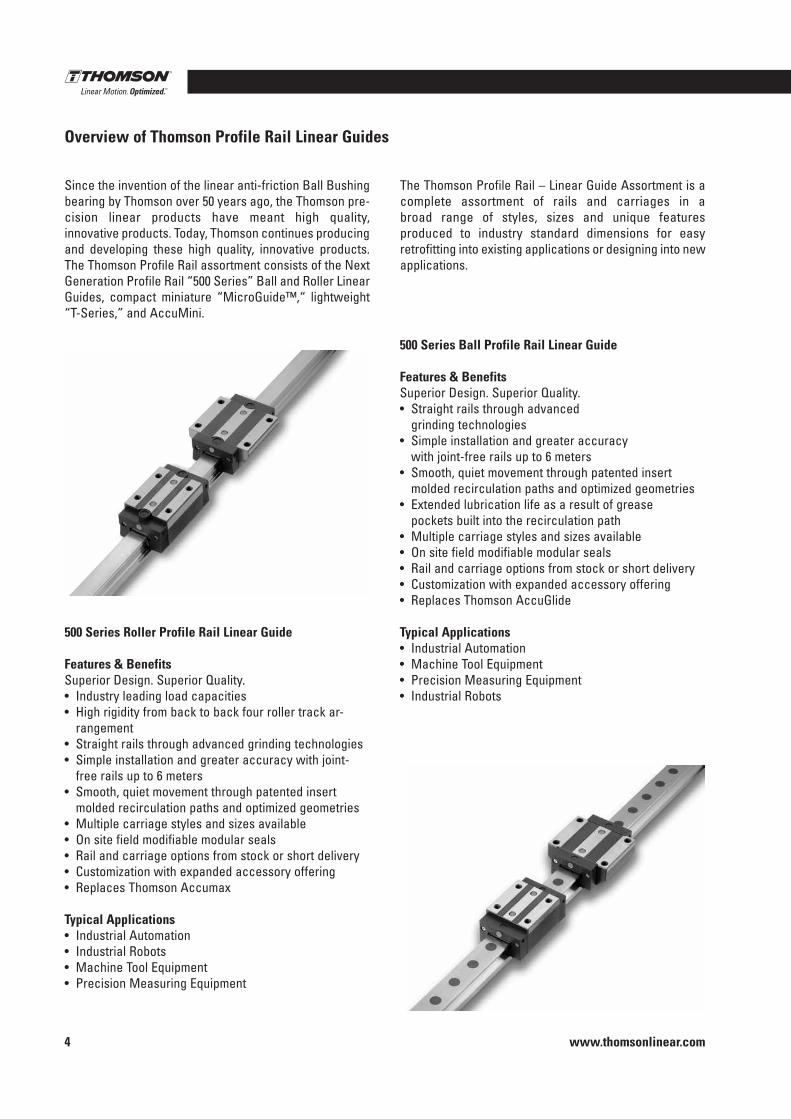
500 Series Ball Profile Rail Linear Guide
Features & BenefitsSuperior Design . Superior Quality .• Straight rails through advanced
grinding technologies• Simple installation and greater accuracy
with joint-free rails up to 6 meters• Smooth, quiet movement through patented insert
molded recirculation paths and optimized geometries• Extended lubrication life as a result of grease
pockets built into the recirculation path• Multiple carriage styles and sizes available• On site field modifiable modular seals• Rail and carriage options from stock or short delivery• Customization with expanded accessory offering• Replaces Thomson AccuGlide
Typical Applications• Industrial Automation • Machine Tool Equipment • Precision Measuring Equipment• Industrial Robots
Overview of Thomson Profile Rail Linear Guides
500 Series Roller Profile Rail Linear Guide
Features & BenefitsSuperior Design . Superior Quality .• Industry leading load capacities• High rigidity from back to back four roller track ar-
rangement• Straight rails through advanced grinding technologies• Simple installation and greater accuracy with joint-
free rails up to 6 meters• Smooth, quiet movement through patented insert
molded recirculation paths and optimized geometries• Multiple carriage styles and sizes available• On site field modifiable modular seals• Rail and carriage options from stock or short delivery• Customization with expanded accessory offering• Replaces Thomson Accumax
Typical Applications• Industrial Automation• Industrial Robots• Machine Tool Equipment• Precision Measuring Equipment
Since the invention of the linear anti-friction Ball Bushing bearing by Thomson over 50 years ago, the Thomson pre-cision linear products have meant high quality, innovative products . Today, Thomson continues producing and developing these high quality, innovative products . The Thomson Profile Rail assortment consists of the Next Generation Profile Rail “500 Series” Ball and Roller Linear Guides, compact miniature “MicroGuide™,“ lightweight “T-Series,” and AccuMini .
The Thomson Profile Rail – Linear Guide Assortment is a complete assortment of rails and carriages in a broad range of styles, sizes and unique features produced to industry standard dimensions for easy retrofitting into existing applications or designing into new applications .
Profile Rail Linear Guides
www.thomsonlinear.com 5
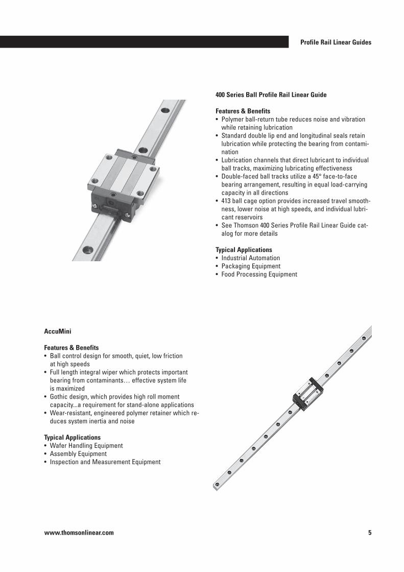
400 Series Ball Profile Rail Linear Guide
Features & Benefits• Polymer ball-return tube reduces noise and vibration
while retaining lubrication• Standard double lip end and longitudinal seals retain
lubrication while protecting the bearing from contami-nation
• Lubrication channels that direct lubricant to individual ball tracks, maximizing lubricating effectiveness
• Double-faced ball tracks utilize a 45° face-to-face bearing arrangement, resulting in equal load-carrying capacity in all directions
• 413 ball cage option provides increased travel smooth-ness, lower noise at high speeds, and individual lubri-cant reservoirs
• See Thomson 400 Series Profile Rail Linear Guide cat-alog for more details
Typical Applications• Industrial Automation• Packaging Equipment• Food Processing Equipment
AccuMini
Features & Benefits• Ball control design for smooth, quiet, low friction
at high speeds• Full length integral wiper which protects important
bearing from contaminants… effective system life is maximized
• Gothic design, which provides high roll moment capacity . . .a requirement for stand-alone applications
• Wear-resistant, engineered polymer retainer which re-duces system inertia and noise
Typical Applications• Wafer Handling Equipment• Assembly Equipment• Inspection and Measurement Equipment
www.thomsonlinear.com6
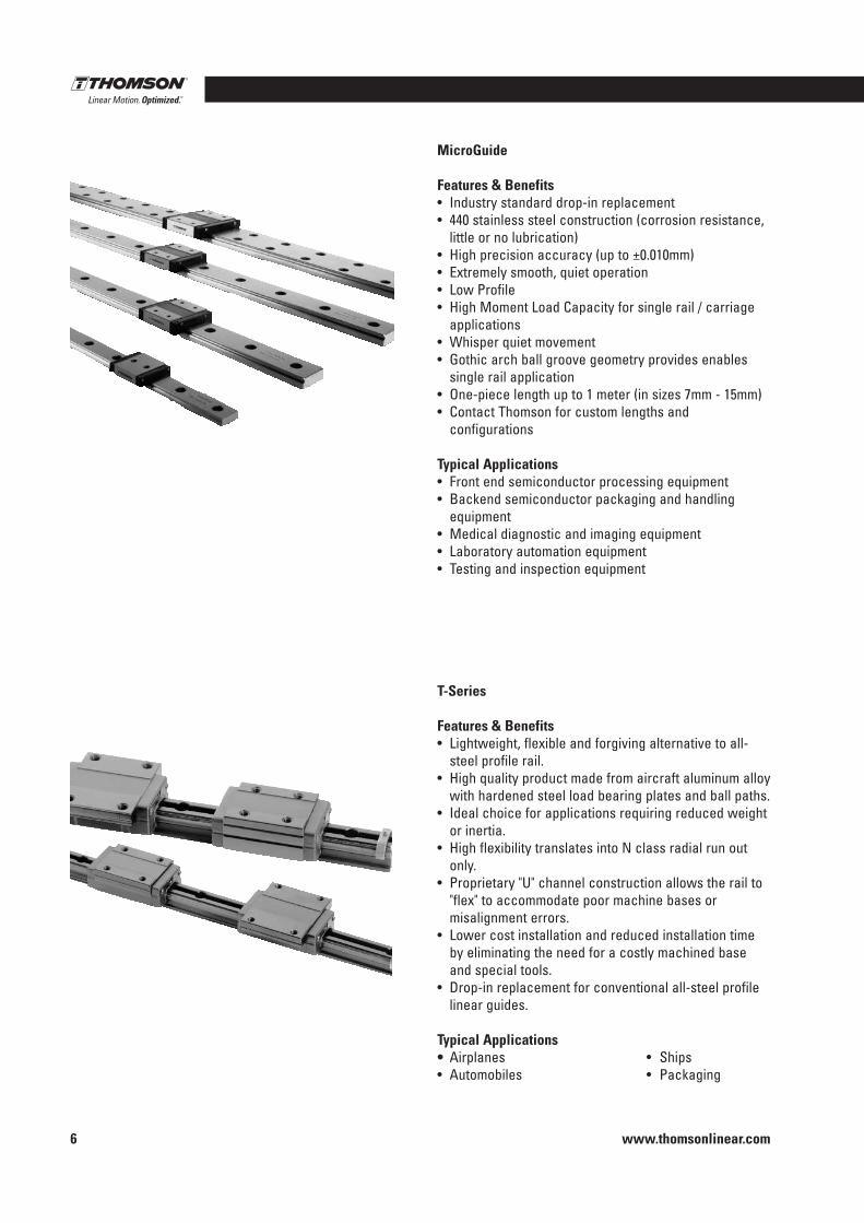
MicroGuide
Features & Benefits• Industry standard drop-in replacement• 440 stainless steel construction (corrosion resistance,
little or no lubrication)• High precision accuracy (up to ±0 .010mm)• Extremely smooth, quiet operation• Low Profile• High Moment Load Capacity for single rail / carriage
applications• Whisper quiet movement• Gothic arch ball groove geometry provides enables
single rail application• One-piece length up to 1 meter (in sizes 7mm - 15mm)• Contact Thomson for custom lengths and
configurations
Typical Applications• Front end semiconductor processing equipment• Backend semiconductor packaging and handling
equipment• Medical diagnostic and imaging equipment• Laboratory automation equipment• Testing and inspection equipment
T-Series
Features & Benefits• Lightweight, flexible and forgiving alternative to all-
steel profile rail .• High quality product made from aircraft aluminum alloy
with hardened steel load bearing plates and ball paths .• Ideal choice for applications requiring reduced weight
or inertia .• High flexibility translates into N class radial run out
only .• Proprietary "U" channel construction allows the rail to
"flex" to accommodate poor machine bases or misalignment errors .
• Lower cost installation and reduced installation time by eliminating the need for a costly machined base and special tools .
• Drop-in replacement for conventional all-steel profile linear guides .
Typical Applications• Airplanes • Ships• Automobiles • Packaging
Profile Rail Linear Guides
www.thomsonlinear.com 7
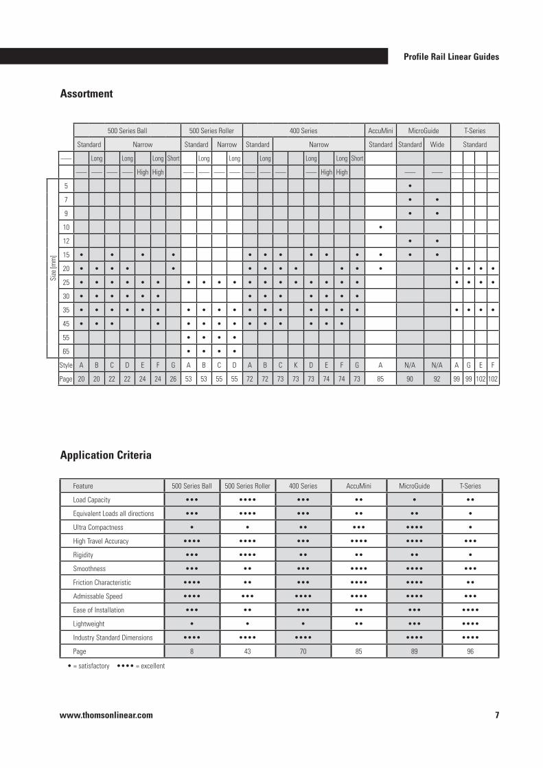
500 Series Ball 500 Series Roller 400 Series AccuMini MicroGuide T-Series
Standard Narrow Standard Narrow Standard Narrow Standard Standard Wide Standard
––– Long Long Long Short Long Long Long Long Long Short
––– ––– ––– ––– High High ––– ––– ––– ––– ––– ––– ––– ––– High High ––– ––– ––– ––– ––– –––
Size
[mm
]
5 •
7 • •
9 • •
10 •
12 • •
15 • • • • • • • • • • • • •
20 • • • • • • • • • • • • • • • •
25 • • • • • • • • • • • • • • • • • • • • • •
30 • • • • • • • • • • • • •
35 • • • • • • • • • • • • • • • • • • • • •
45 • • • • • • • • • • • • • •
55 • • • •
65 • • • •
Style A B C D E F G A B C D A B C K D E F G A N/A N/A A G E F
Page 20 20 22 22 24 24 26 53 53 55 55 72 72 73 73 73 74 74 73 85 90 92 99 99 102 102
Application Criteria
Feature 500 Series Ball 500 Series Roller 400 Series AccuMini MicroGuide T-Series
Load Capacity ••• •••• ••• •• • ••
Equivalent Loads all directions ••• •••• ••• •• •• •
Ultra Compactness • • •• ••• •••• •
High Travel Accuracy •••• •••• ••• •••• •••• •••
Rigidity ••• •••• •• •• •• •
Smoothness ••• •• ••• •••• •••• •••
Friction Characteristic •••• •• ••• •••• •••• ••
Admissable Speed •••• ••• •••• •••• •••• •••
Ease of Installation ••• •• ••• •• ••• ••••
Lightweight • • • •• ••• ••••
Industry Standard Dimensions •••• •••• •••• •••• ••••
Page 8 43 70 85 89 96
• = satisfactory •••• = excellent
Assortment
www.thomsonlinear.com8
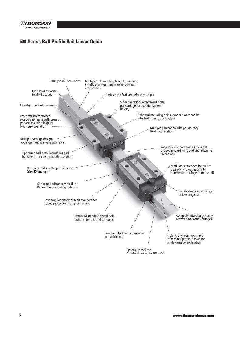
Industry standard dimensions
High load capacities in all directions
Multiple rail accuracies Multiple rail mounting hole plug options,or rails that mount up from underneath are available
Both sides of rail are reference edges
Six-runner block attachment boltsper carriage for superior systemrigidity
Universal mounting holes–runner blocks can be attached from top or bottom
Multiple lubrication inlet points, easyfield modification
Superior rail straightness as a resultof advanced grinding and straighteningtechnology
Modular accessories for on site upgrade without having toremove the carriage from the rail
Removable double lip seal or low drag seal
High rigidity from optimizedtrapezoidal profile, allows for single carriage application
Speeds up to 5 m/sAccelerations up to 100 m/s2
Two point ball contact resultingin low friction
Extended standard dowel holeoptions for rails and carriages
Low drag longitudinal seals standard for added protection along rail surface
Corrosion resistance with ThinDense Chrome plating optional
One piece rail length up to 6 meters(size 25 and up)
Optimized ball path geometries andtransitions for quiet, smooth operation
Multiple carriage designs, accuracies and preloads available
Patented insert moldedrecirculation path with greasepockets resulting in quiet,low noise operation
Complete interchangeabilitybetween rails and carriages
500 Series Ball Profile Rail Linear Guide
Profile Rail Linear Guides
www.thomsonlinear.com 9
500 Series Ball
Profile Rail
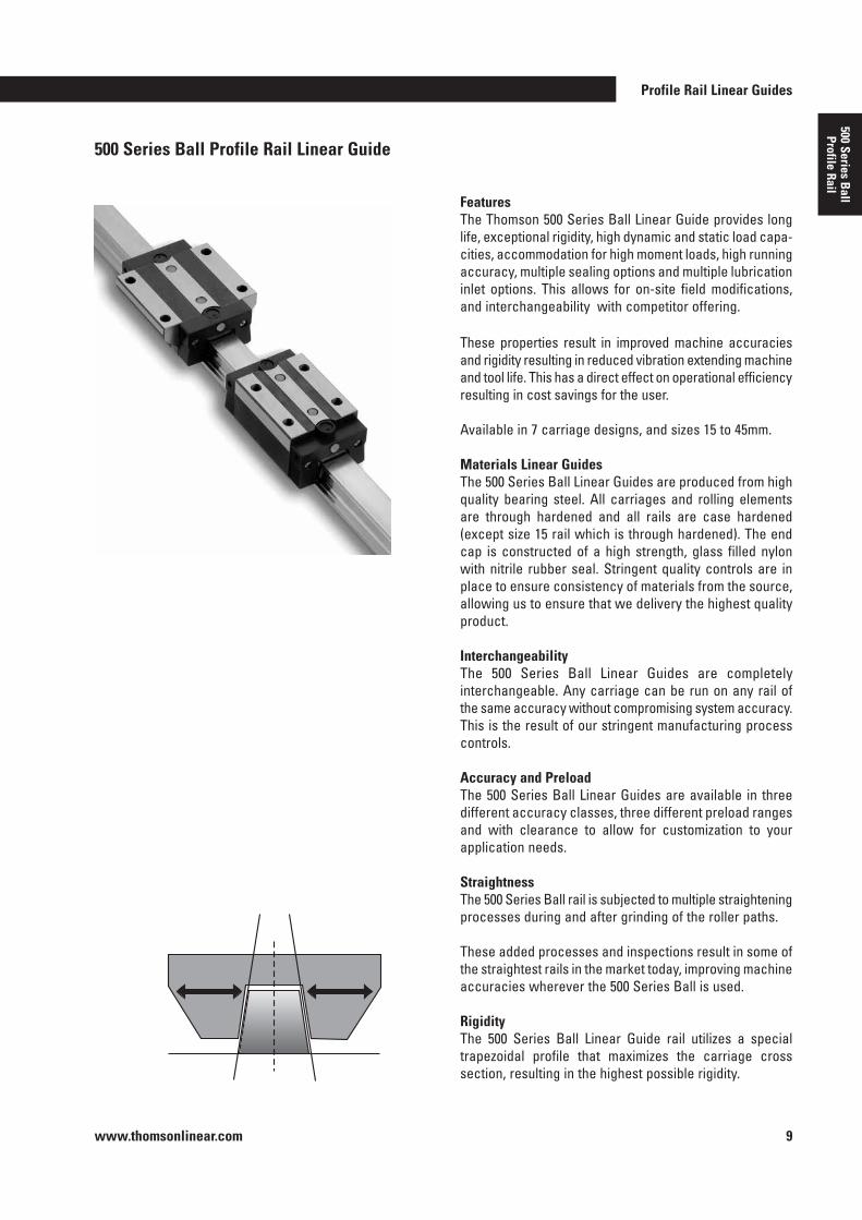
FeaturesThe Thomson 500 Series Ball Linear Guide provides long life, exceptional rigidity, high dynamic and static load capa-cities, accommodation for high moment loads, high running accuracy, multiple sealing options and multiple lubrication inlet options . This allows for on-site field modifications, and interchangeability with competitor offering .
These properties result in improved machine accuracies and rigidity resulting in reduced vibration extending machine and tool life . This has a direct effect on operational efficiency resulting in cost savings for the user .
Available in 7 carriage designs, and sizes 15 to 45mm .
Materials Linear GuidesThe 500 Series Ball Linear Guides are produced from high quality bearing steel . All carriages and rolling elements are through hardened and all rails are case hardened (except size 15 rail which is through hardened) . The end cap is constructed of a high strength, glass filled nylon with nitrile rubber seal . Stringent quality controls are in place to ensure consistency of materials from the source, allowing us to ensure that we delivery the highest quality product .
Interchangeability The 500 Series Ball Linear Guides are completely interchangeable . Any carriage can be run on any rail of the same accuracy without compromising system accuracy . This is the result of our stringent manufacturing process controls .
Accuracy and PreloadThe 500 Series Ball Linear Guides are available in three different accuracy classes, three different preload ranges and with clearance to allow for customization to your appli cation needs .
StraightnessThe 500 Series Ball rail is subjected to multiple straightening processes during and after grinding of the roller paths .
These added processes and inspections result in some of the straightest rails in the market today, improving machine accuracies wherever the 500 Series Ball is used .
RigidityThe 500 Series Ball Linear Guide rail utilizes a special trapezoidal profile that maximizes the carriage cross section, resulting in the highest possible rigidity .
500 Series Ball Profile Rail Linear Guide
www.thomsonlinear.com10
500 Series Ball Profile Rail Linear Guide
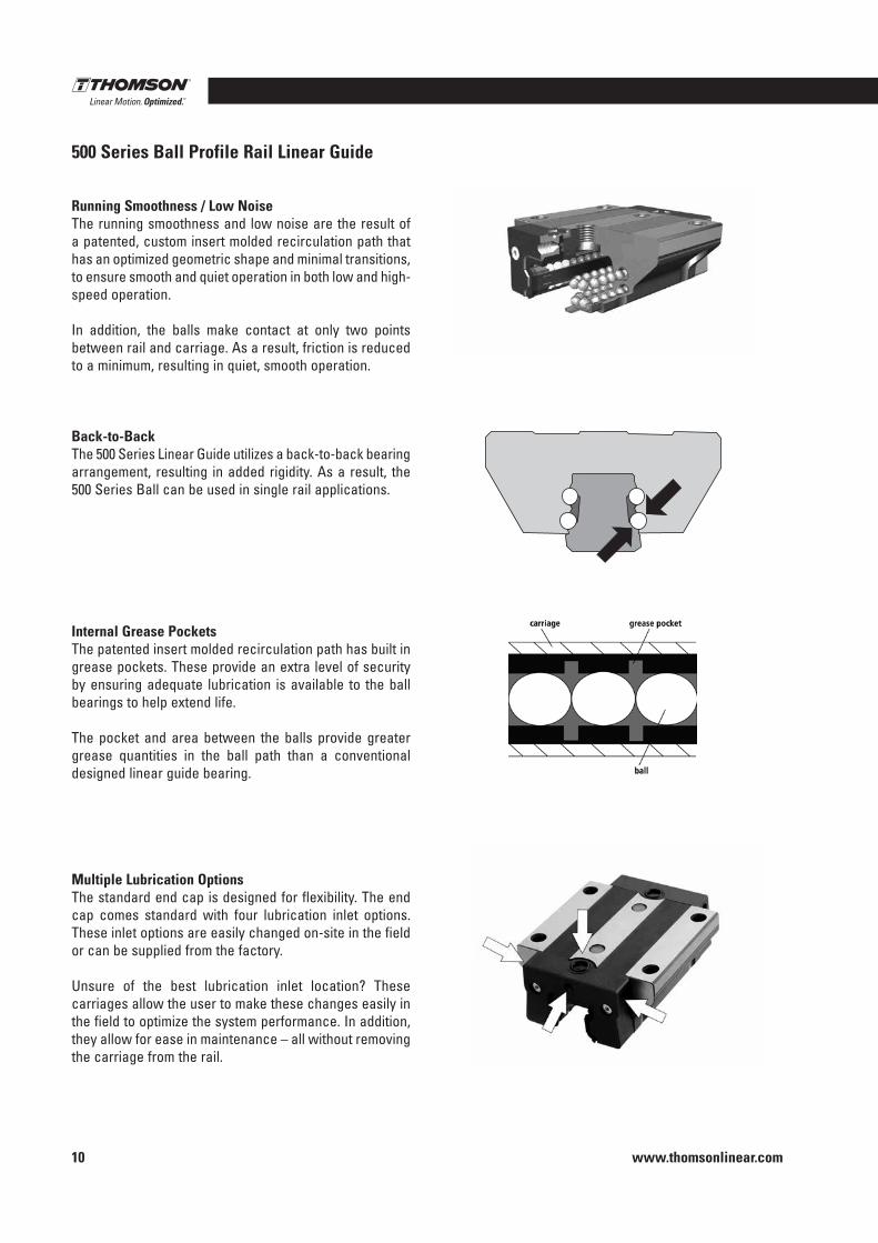
Running Smoothness / Low NoiseThe running smoothness and low noise are the result of a patented, custom insert molded recirculation path that has an optimized geometric shape and minimal transitions, to ensure smooth and quiet operation in both low and high-speed operation .
In addition, the balls make contact at only two points between rail and carriage . As a result, friction is reduced to a minimum, resulting in quiet, smooth operation .
Back-to-BackThe 500 Series Linear Guide utilizes a back-to-back bearing arrangement, resulting in added rigidity . As a result, the 500 Series Ball can be used in single rail applications .
Internal Grease PocketsThe patented insert molded recirculation path has built in grease pockets . These provide an extra level of security by ensuring adequate lubrication is available to the ball bearings to help extend life .
The pocket and area between the balls provide greater grease quantities in the ball path than a conventional designed linear guide bearing .
Multiple Lubrication OptionsThe standard end cap is designed for flexibility . The end cap comes standard with four lubrication inlet options . These inlet options are easily changed on-site in the field or can be supplied from the factory .
Unsure of the best lubrication inlet location? These carriages allow the user to make these changes easily in the field to optimize the system performance . In addition, they allow for ease in maintenance – all without removing the carriage from the rail .
Profile Rail Linear Guides
www.thomsonlinear.com 11
500 Series Ball
Profile Rail
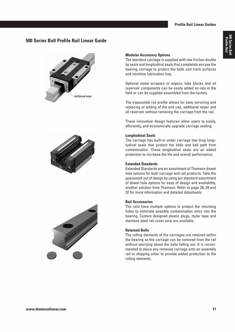
Modular Accessory OptionsThe standard carriage is supplied with low friction double lip seals and longitudinal seals that completely encase the bearing carriage to protect the balls and track surfaces and minimize lubrication loss .
Optional metal scrapers or wipers, lube blocks and oil reservoir components can be easily added on-site in the field or can be supplied assembled from the factory .
The trapezoidal rail profile allows for easy servicing and replacing or adding of the end cap, additional wiper and oil reservoir without removing the carriage from the rail .
These innovative design features allow users to easily, efficiently, and economically upgrade carriage sealing .
Longitudinal SealsThe carriage has built-in under carriage low drag longi-tudinal seals that protect the balls and ball path from contamination . These longitudinal seals are an added protection to increase the life and overall performance .
Extended StandardsExtended Standards are an assortment of Thomson dowel hole options for both carriage and rail products . Take the guesswork out of design by using our standard assortment of dowel hole options for ease of design and availability, another solution from Thomson . Refer to page 28, 29 and 32 for more information and detailed datasheets .
Rail AccessoriesThe rails have multiple options to protect the mounting holes to eliminate possible contamination entry into the bearing . Custom designed plastic plugs, mylar tape and stainless steel rail cover strip are available .
Retained BallsThe rolling elements of the carriages are retained within the bearing so the carriage can be removed from the rail without worrying about the balls falling out . It is recom-mended to place any removed carriage onto an assembly rail or shipping arbor to provide added protection to the rolling elements .
500 Series Ball Profile Rail Linear Guide
www.thomsonlinear.com12
500 Series Profile Rail Enhanced Carriage
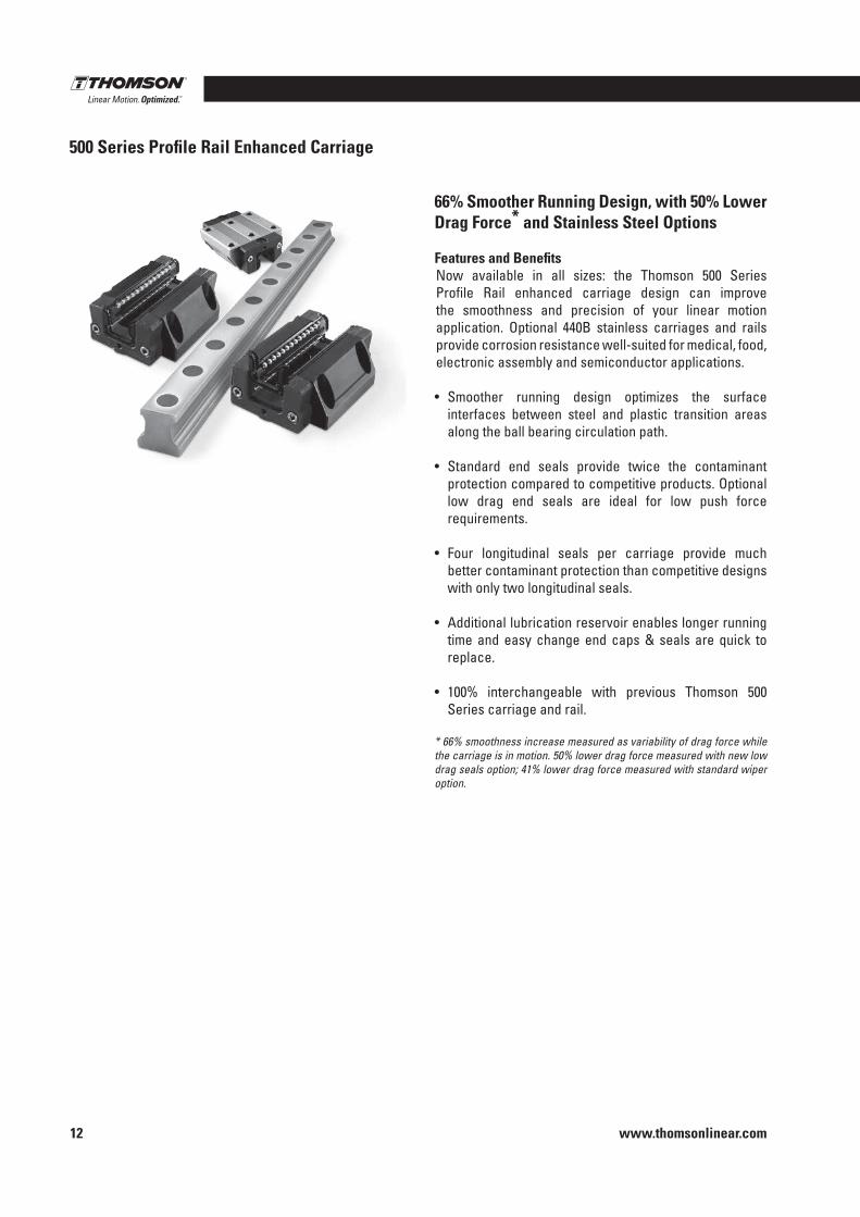
66% Smoother Running Design, with 50% Lower Drag Force* and Stainless Steel Options
Features and BenefitsNow available in all sizes: the Thomson 500 Series Profile Rail enhanced carriage design can improve the smoothness and precision of your linear motion application . Optional 440B stainless carriages and rails provide corrosion resistance well-suited for medical, food, electronic assembly and semiconductor applications .
• Smoother running design optimizes the surface interfaces between steel and plastic transition areas along the ball bearing circulation path .
• Standard end seals provide twice the contaminant protection compared to competitive products . Optional low drag end seals are ideal for low push force requirements .
• Four longitudinal seals per carriage provide much better contaminant protection than competitive designs with only two longitudinal seals .
• Additional lubrication reservoir enables longer running time and easy change end caps & seals are quick to replace .
• 100% interchangeable with previous Thomson 500 Series carriage and rail .
* 66% smoothness increase measured as variability of drag force while the carriage is in motion. 50% lower drag force measured with new low drag seals option; 41% lower drag force measured with standard wiper option.
Profile Rail Linear Guides
www.thomsonlinear.com 13
500 Series Ball
Profile Rail
500 Series Ball Profile Rail Linear Guide
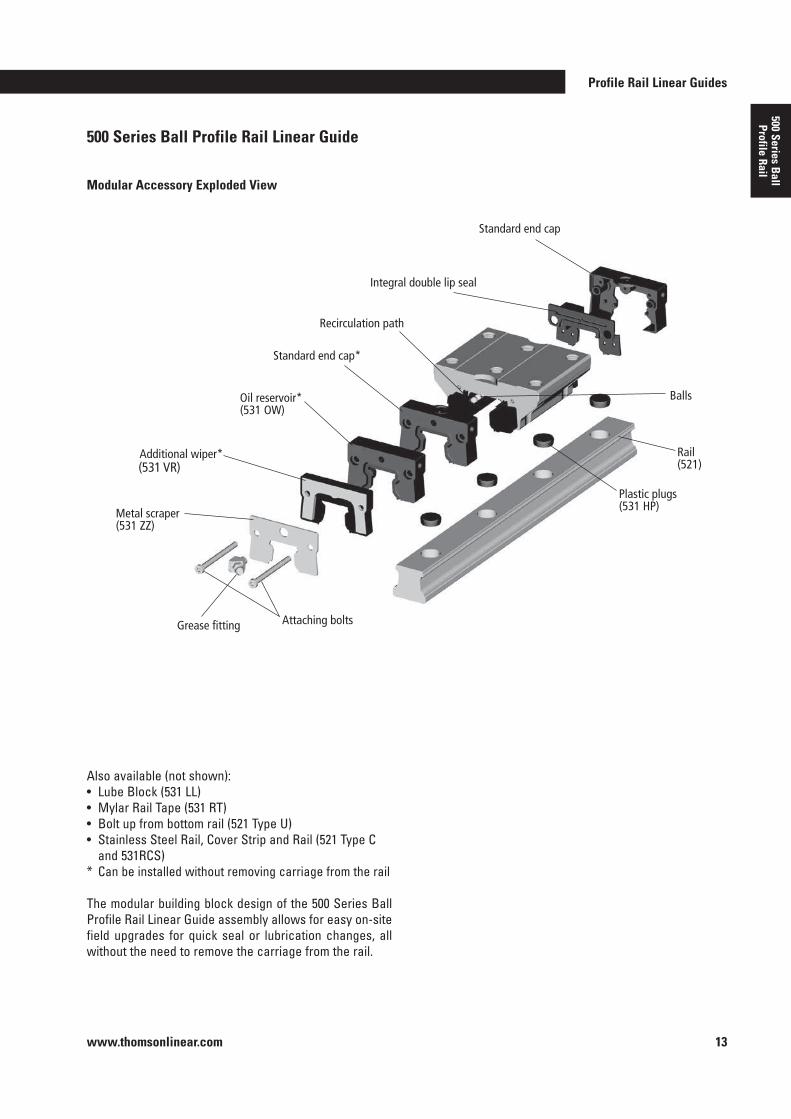
Modular Accessory Exploded View
Also available (not shown):• Lube Block (531 LL)• Mylar Rail Tape (531 RT)• Bolt up from bottom rail (521 Type U)• Stainless Steel Rail, Cover Strip and Rail (521 Type C
and 531RCS)* Can be installed without removing carriage from the rail
The modular building block design of the 500 Series Ball Profile Rail Linear Guide assembly allows for easy on-site field upgrades for quick seal or lubrication changes, all without the need to remove the carriage from the rail .
Standard end cap* (531 EC)
Integral double lip seal
Recirculation path
Oil reservoir* (531 OW)
Additional wiper* (531 WR or VR)
Metal scraper (531 ZZ)
Grease fitting Attaching bolts
Plastic plugs (531 HP)
Rail (521)
Balls
Standard end cap (531 EC)
(531 VR)
www.thomsonlinear.com14
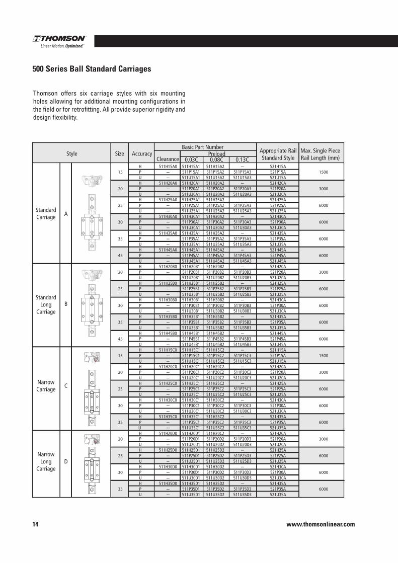
500 Series Ball Standard Carriages
15
20
25
30
35
45
20
25
30
35
45
15
20
25
30
35
20
25
30
35
1500
3000
6000
6000
6000
6000
3000
6000
6000
6000
6000
1500
3000
6000
6000
6000
3000
6000
6000
6000
511H15A0--
511H20A0--
511H25A0--
511H30A0--
511H35A0--
511H45A0--
511H20B0--
511H25B0--
511H30B0--
511H35B0--
511H45B0--
511H15C0--
511H20C0--
511H25C0--
511H30C0--
511H35C0--
511H20D0--
511H25D0--
511H30D0--
511H35D0--
HPUHPUHPUHPUHPUHPUHPUHPUHPUHPUHPUHPUHPUHPUHPUHPU HPUHPUHPUHPU
511H15A1511P15A1511U15A1511H20A1511P20A1511U20A1511H25A1511P25A1511U25A1511H30A1511P30A1511U30A1511H35A1511P35A1511U35A1511H45A1511P45A1511U45A1511H20B1511P20B1511U20B1511H25B1511P25B1511U25B1511H30B1511P30B1511U30B1511H35B1511P35B1511U35B1511H45B1511P45B1511U45B1511H15C1511P15C1511U15C1511H20C1511P20C1511U20C1511H25C1511P25C1511U25C1511H30C1511P30C1511U30C1511H35C1511P35C1511U35C1511H20D1511P20D1511U20D1511H25D1511P25D1511U25D1511H30D1511P30D1511U30D1511H35D1511P35D1511U35D1
511H15A2511P15A2511U15A2511H20A2511P20A2511U20A2511H25A2511P25A2511U25A2511H30A2511P30A2511U30A2511H35A2511P35A2511U35A2511H45A2511P45A2511U45A2511H20B2511P20B2511U20B2511H25B2511P25B2511U25B2511H30B2511P30B2511U30B2511H35B2511P35B2511U35B2511H45B2511P45B2511U45B2511H15C2511P15C2511U15C2511H20C2511P20C2511U20C2511H25C2511P25C2511U25C2511H30C2511P30C2511U30C2511H35C2511P35C2511U35C2511H20C2511P20D2511U20D2511H25D2511P25D2511U25D2511H30D2511P30D2511U30D2511H35D2511P35D2511U35D2
-511P15A3511U15A3
-511P20A3511U20A3
-511P25A3511U25A3
-511P30A3511U30A3
-511P35A3511U35A3
-511P45A3511U45A3
-511P20B3511U20B3
-511P25B3511U25B3
-511P30B3511U30B3
-511P35B3511U35B3
-511P45B3511U45B3
-511P15C3511U15C3
-511P20C3511U20C3
-511P25C3511U25C3
-511P30C3511U30C3
-511P35C3511U35C3
-511P20D3511U20D3
-511P25D3511U25D3
-511P30D3511U30D3
-511P35D3511U35D3
521H15A521P15A521U15A521H20A521P20A521U20A521H25A521P25A521U25A521H30A521P30A521U30A521H35A521P35A521U35A521H45A521P45A521U45A521H20A521P20A521U20A521H25A521P25A521U25A521H30A521P30A521U30A521H35A521P35A521U35A521H45A521P45A521U45A521H15A521P15A521U15A521H20A521P20A521U20A521H25A521P25A521U25A521H30A521P30A521U30A521H35A521P35A521U35A521H20A521P20A521U20A521H25A521P25A521U25A521H30A521P30A521U30A521H35A521P35A521U35A
SizeStyle
StandardCarriage A
B
C
NarrowLong
Carriage
NarrowCarriage
StandardLong
Carriage
D
AccuracyClearance 0.03C 0.08C
PreloadBasic Part Number
0.13C
Appropriate RailStandard Style
Max. Single PieceRail Length (mm)
Thomson offers six carriage styles with six mounting holes allowing for additional mounting configurations in the field or for retrofitting . All provide superior rigidity and design flexibility .
Profile Rail Linear Guides
www.thomsonlinear.com 15
500 Series Ball
Profile Rail
15 25 30 35 45 25 30 35 45 15 20
1500 6000 6000 6000 6000 6000 6000 6000 6000 1500 3000
511H15E0 - -
511H25E0 - -
511H30E0 - -
511H35E0 - -
511H45E0 - -
511H25F0 - -
511H30F0 - -
511H35F0 - -
511H45F0 - -
511H15G0 - -
511H20G0 - -
H P U H P U H P U H P U H P U H P U H P U H P U H P U H P U H P U
511H15E1511P15E1511U15E1511H25E1511P25E1511U25E1511H30E1511P30E1511U30E1511H35E1511P35E1511U35E1511H45E1511P45E1511U45E1511H25F1511P25F1511U25F1511H23F1511P30F1511U30F1511H35F1511P35F1511U35F1511H45F1511P45F1511U45F1511H15G1511P15G1511U15G1511H20G1511P20G1511U20G1
511H15E2511P15E2511U15E2511H25E2511P25E2511U25E2511H30E2511P30E2511U30E2511H35E2511P35E2511U35E2511H45E2511P45E2511U45E2511H25F2511P25F2511U25F2511H30F2511P30F2511U30F2511H35F2511P35F2511U35F2511H45F2511P45F2511U45F2511H15G2511P15G2511U15G2511H20G2511P20G2511U20G2
- 511P15E3 511U15E3
- 511P25E3 511U25E3
- 511P30E3 511U30E3
- 511P35E3 511U35E3
- 511P45E3 511U45E3
- 511P20F3 511U20F3
- 511P30F3 511U30F3
- 511P35F3 511U35F3
- 511P45F3 511U45F3
- 511P15G3 511U15G3
- 511P20G3 511U20G3
521H15A 521P15A 521U15A 521H25A 521P25A 521U25A 521H30A 521P30A 521U30A 521H35A 521P35A 521U35A 521H45A 521P45A 521U45A 521H25A 521P25A 521U25A 521H30A 521P30A 521U30A 521H35A 521P35A 521U35A 521H45A 521P45A 521U45A 521H15A 521P15A 521U15A 521H20A 521P20A 521U20A
SizeStyle
NarrowHigh
Carriage E
F
GNarrowShort
Carriage
NarrowHighLong
Carriage
AccuracyClearance 0.03C 0.08C
PreloadBasic Part Number
0.13C
Appropriate RailStandard Style
Max. Single PieceRail Length (mm)
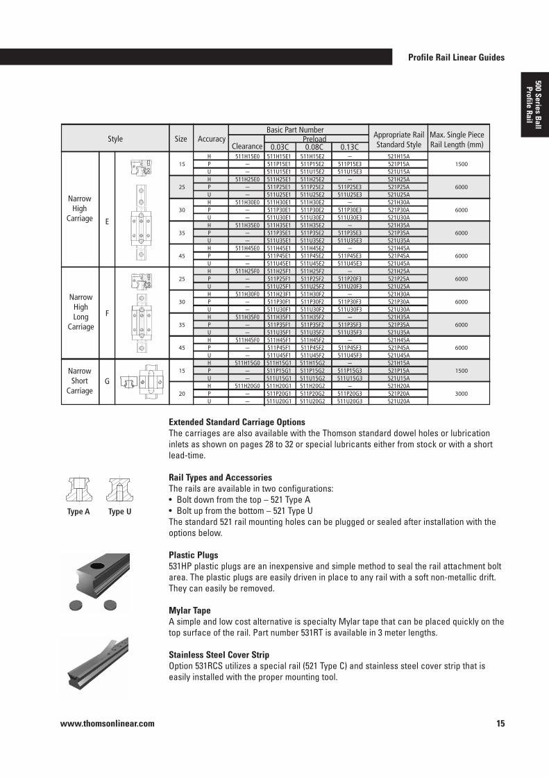
Extended Standard Carriage OptionsThe carriages are also available with the Thomson standard dowel holes or lubrication inlets as shown on pages 28 to 32 or special lubricants either from stock or with a short lead-time .
Rail Types and AccessoriesThe rails are available in two configurations:• Bolt down from the top – 521 Type A• Bolt up from the bottom – 521 Type UThe standard 521 rail mounting holes can be plugged or sealed after installation with the options below .
Plastic Plugs531HP plastic plugs are an inexpensive and simple method to seal the rail attachment bolt area . The plastic plugs are easily driven in place to any rail with a soft non-metallic drift . They can easily be removed .
Mylar TapeA simple and low cost alternative is specialty Mylar tape that can be placed quickly on the top surface of the rail . Part number 531RT is available in 3 meter lengths .
Stainless Steel Cover StripOption 531RCS utilizes a special rail (521 Type C) and stainless steel cover strip that is easily installed with the proper mounting tool .
Type A Type U
500 Series Roller Profile Rail
400 Series Profile Rail
AccuM
iniM
icroGuide
www.thomsonlinear.com16
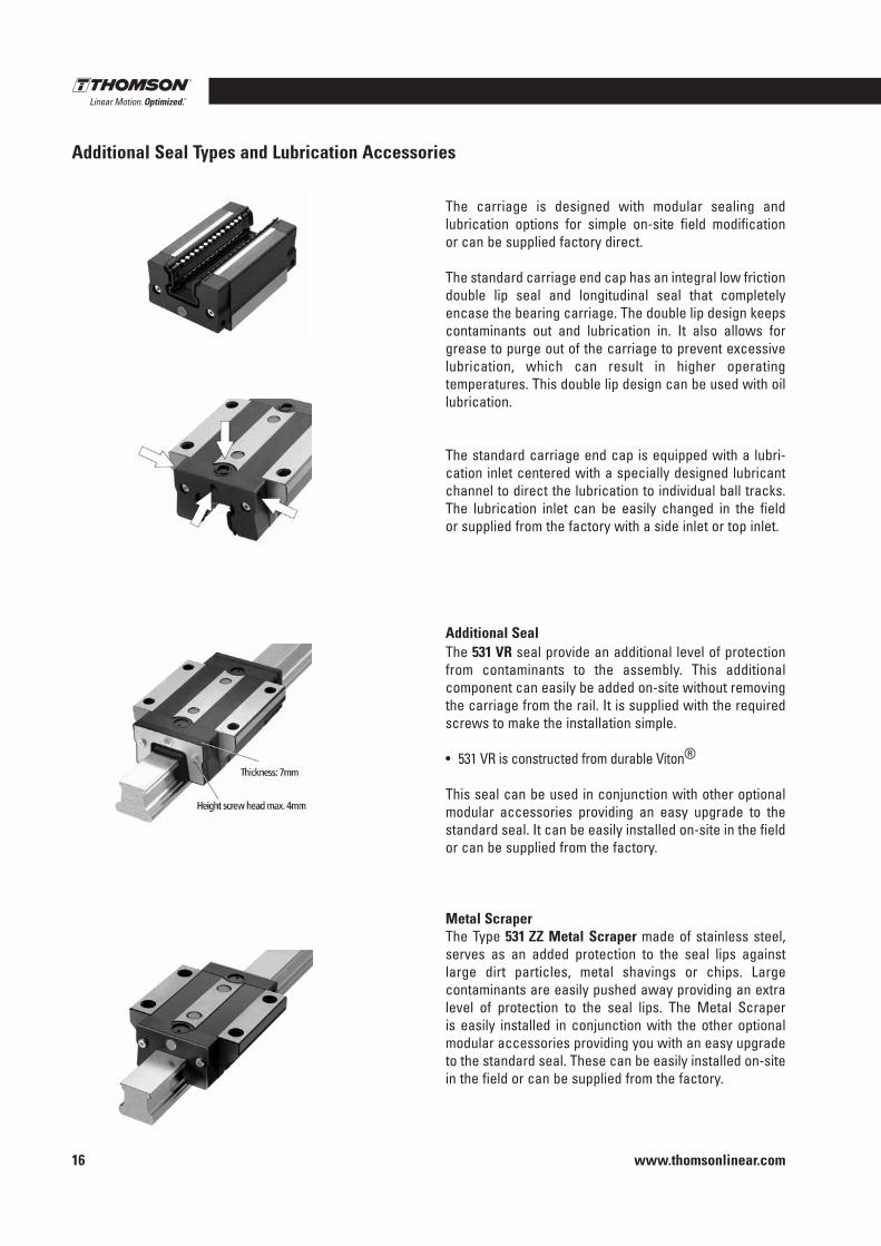
The carriage is designed with modular sealing and lubrication options for simple on-site field modification or can be supplied factory direct .
The standard carriage end cap has an integral low friction double lip seal and longitudinal seal that completely encase the bearing carriage . The double lip design keeps contaminants out and lubrication in . It also allows for grease to purge out of the carriage to prevent excessive lubrication, which can result in higher operating temperatures . This double lip design can be used with oil lubrication .
The standard carriage end cap is equipped with a lubri-cation inlet centered with a specially designed lubricant channel to direct the lubrication to individual ball tracks . The lubrication inlet can be easily changed in the field or supplied from the factory with a side inlet or top inlet .
Additional SealThe 531 VR seal provide an additional level of protection from contaminants to the assembly . This additional component can easily be added on-site without removing the carriage from the rail . It is supplied with the required screws to make the installation simple .
• 531 VR is constructed from durable Viton®
This seal can be used in conjunction with other optional modular accessories providing an easy upgrade to the standard seal . It can be easily installed on-site in the field or can be supplied from the factory .
Metal ScraperThe Type 531 ZZ Metal Scraper made of stainless steel, serves as an added protection to the seal lips against large dirt particles, metal shavings or chips . Large contaminants are easily pushed away providing an extra level of protection to the seal lips . The Metal Scraper is easily installed in conjunction with the other optional modular accessories providing you with an easy upgrade to the standard seal . These can be easily installed on-site in the field or can be supplied from the factory .
Additional Seal Types and Lubrication Accessories
Profile Rail Linear Guides
www.thomsonlinear.com 17
500 Series Ball
Profile Rail
Type Relative Drag
Standard carriage •Viton® Wiper (531 VR) • • •Metal Scraper (531 ZZ) •Oil Reservoir (531 OW) • •Lube Block (531 LL) • • • •
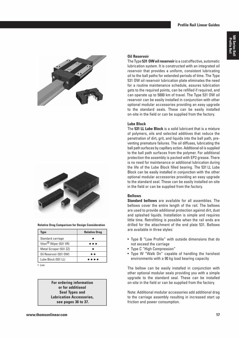
Oil ReservoirThe Type 531 OW oil reservoir is a cost effective, automatic lubrication system . It is constructed with an integrated oil reservoir that provides a uniform, consistent lubricating oil to the ball paths for extended periods of time . The Type 531 OW oil reservoir lubrication plate eliminates the need for a routine maintenance schedule, assures lubrication gets to the required points, can be refilled if required, and can operate up to 5000 km of travel . The Type 531 OW oil reservoir can be easily installed in conjunction with other optional modular accessories providing an easy upgrade to the standard seals . These can be easily installed on-site in the field or can be supplied from the factory .
Lube BlockThe 531 LL Lube Block is a solid lubricant that is a mixture of polymers, oils and selected additives that reduce the penetration of dirt, grit, and liquids into the ball path, pre-venting premature failures . The oil diffuses, lubricating the ball path surfaces by capillary action . Additional oil is supplied to the ball path surfaces from the polymer . For additional protection the assembly is packed with EP2 grease . There is no need for maintenance or additional lubrication during the life of the Lube Block filled bearing . The 531 LL Lube Block can be easily installed in conjunction with the other optional modular accessories providing an easy upgrade to the standard seal . These can be easily installed on-site in the field or can be supplied from the factory .
BellowsStandard bellows are available for all assemblies . The bellows cover the entire length of the rail . The bellows are used to provide additional protection against dirt, dust and splashed liquids . Installation is simple and requires little time . Retrofitting is possible when the rail ends are drilled for the attachment of the end plate 531 . Bellows are available in three styles:
• Type B “Low Profile” with outside dimensions that do not exceed the carriage
• Type C “High Compression” • Type W “Walk On” capable of handling the harshest
environments with a 90 kg load bearing capacity
The bellow can be easily installed in conjunction with other optional modular seals providing you with a simple upgrade to the standard seal . These can be installed on-site in the field or can be supplied from the factory .
Note: Additional modular accessories add additional drag to the carriage assembly resulting in increased start up friction and power consumption .
For ordering information or for additional Seal Types and
Lubrication Accessories, see pages 36 to 37 .
• Low
Relative Drag Comparison for Design Consideration
www.thomsonlinear.com18
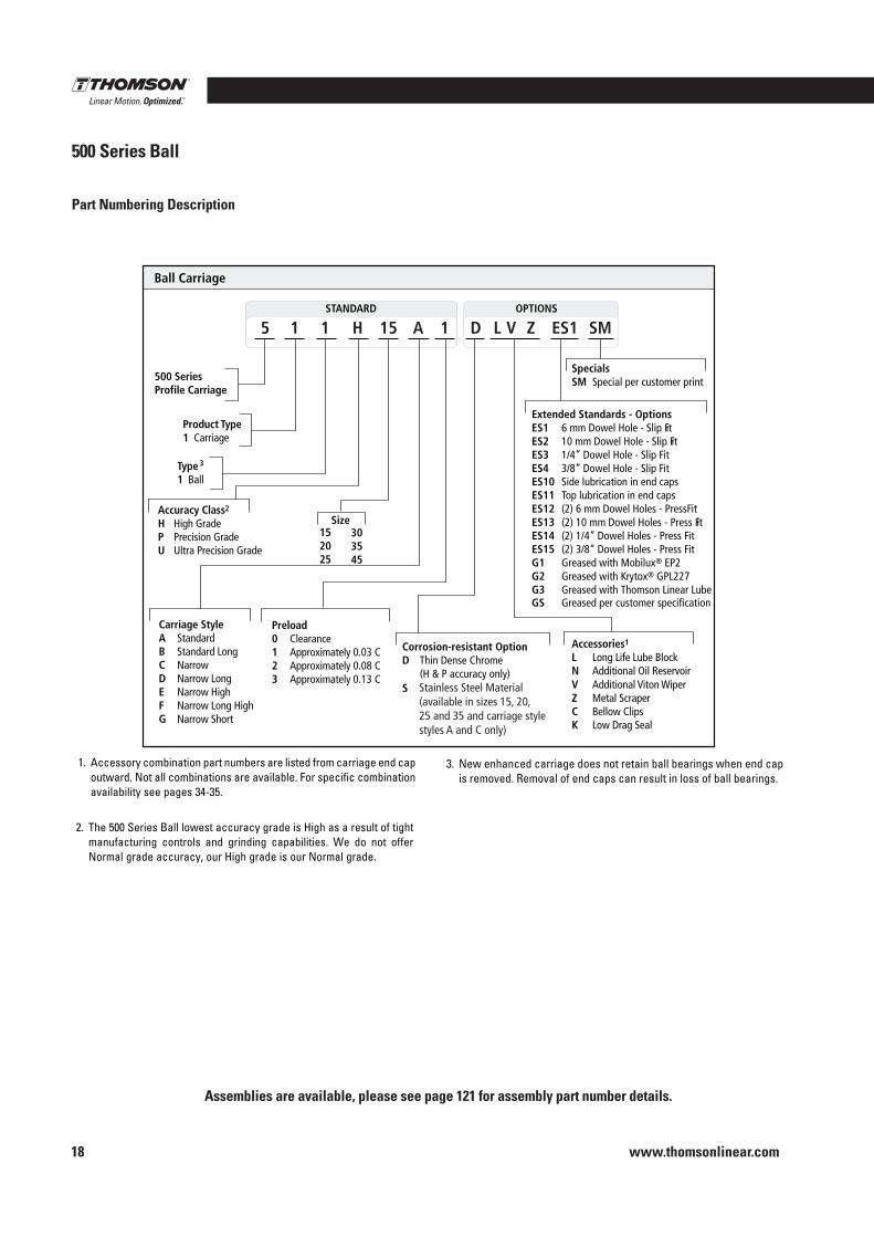
Part Numbering Description
500 Series Ball
Standard STANDARD OPTIONS
Ball Carriage
500 Series Profile Carriage
Product Type 1 Carriage
5 1 1 H 15 A 1 ES1 SM L V Z D
Specials SM Special per customer print
Extended Standards - Options ES1 6 mm Dowel Hole - Slip Fit ES2 10 mm Dowel Hole - Slip Fit ES3 1/4” Dowel Hole - Slip Fit ES4 3/8” Dowel Hole - Slip Fit ES10 Side lubrication in end caps ES11 Top lubrication in end caps ES12 (2) 6 mm Dowel Holes - Press Fit ES13 (2) 10 mm Dowel Holes - Press Fit ES14 (2) 1/4” Dowel Holes - Press Fit ES15 (2) 3/8” Dowel Holes - Press Fit G1 Greased with Mobilux® EP2
G2 Greased with Krytox® GPL227 G3 Greased with Thomson Linear LubeGS Greased per customer specification
Accuracy Class2
H High Grade P Precision Grade U Ultra Precision Grade
Size 152025
Carriage Style A Standard B Standard Long C Narrow D Narrow Long E Narrow High F Narrow Long High G Narrow Short
Preload 0 Clearance 1 Approximately 0.03 C2 Approximately 0.08 C3 Approximately 0.13 C
Type 1 Ball
Accessories1
L Long Life Lube Block N Additional Oil Reservoir
V Additional Viton Wiper Z Metal Scraper
C Bellow Clips K Low Drag Seal
Corrosion-resistant OptionD
S Stainless Steel Material(available in sizes 15 and20 and carriage styles A andC only)
Thin Dense Chrome(H & P accuracy only)
1. Accessory combination part numbers are listed from carriage end cap outward. Not all combinations are available. For specific combination availability see pages 34-35.
2.
The 500 Series Ball lowest accuracy grade is High as a result of tight manufacturing controls and grinding capabilities. We do not offer Normal grade accuracy, our High grade is our Normal grade.
303545
3. New enhanced carriage does not retain ball bearings when end cap is removed. Removal of end caps can result in loss of ball bearings.
3
500 Series Roller Profile Rail
400 Series Profile Rail
AccuM
iniM
icroGuide
Assemblies are available, please see page 121 for assembly part number details .
Stainless Steel Material (available in sizes 15, 20,25 and 35 and carriage stylestyles A and C only)
Profile Rail Linear Guides
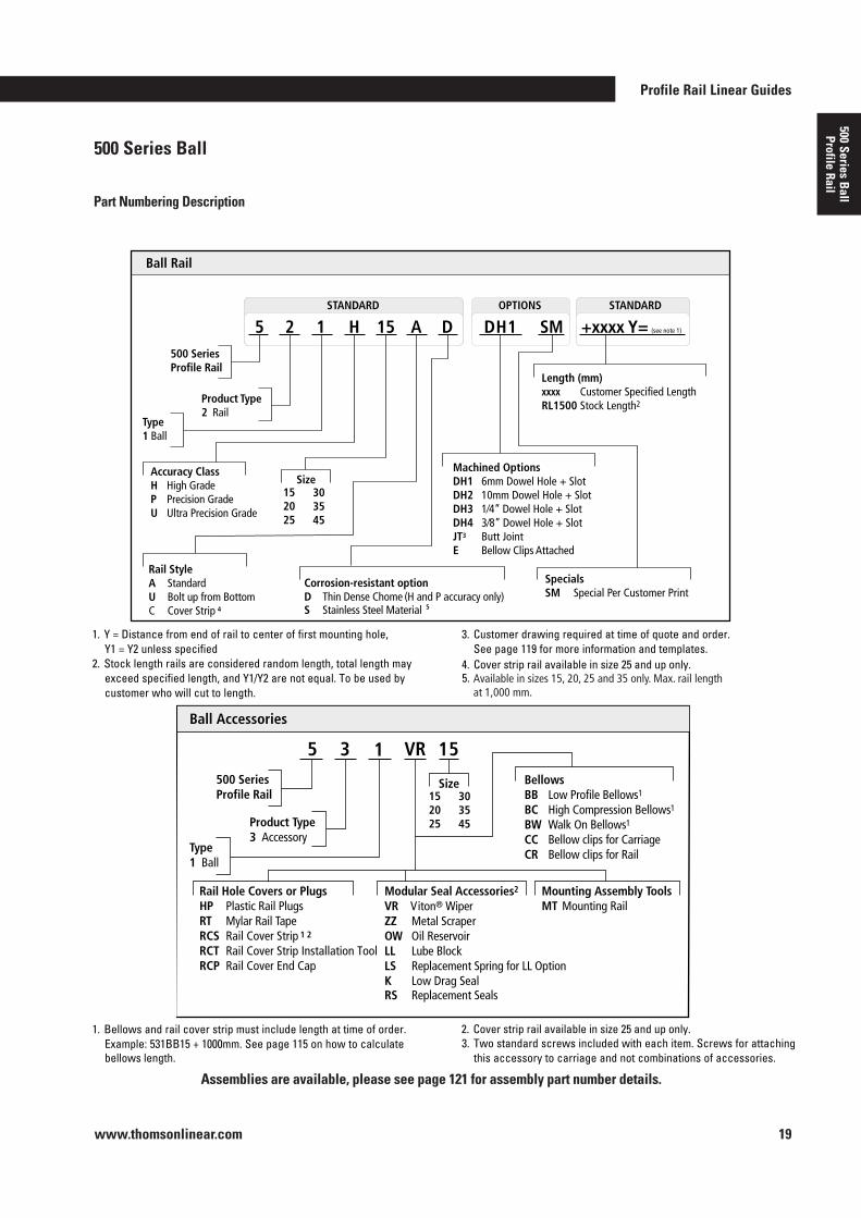
www.thomsonlinear.com 19
500 Series Ball
Profile Rail
OPTIONS STANDARD STANDARD
Ball Rail
500 Series Profile Rail
Product Type 2 Rail
5 2 1 H 15 A D SM +xxxx Y= (see note 1) DH1
Length (mm) xxxx Customer Specified Length RL1500 Stock Length2
Specials SM Special Per Customer Print
Machined Options DH1 6mm Dowel Hole + Slot DH2 10mm Dowel Hole + Slot DH3 1⁄4” Dowel Hole + Slot DH4 3⁄8” Dowel Hole + Slot JT3 Butt Joint E Bellow Clips Attached
Accuracy Class H High Grade P Precision Grade U Ultra Precision Grade
Size 152025
Rail Style A Standard UC
Bolt up from BottomCover Strip
Corrosion-resistant option D Thin Dense Chome (H and P accuracy only) S Stainless Steel Material
Type 1 Ball
Ball Accessories
500 Series Profile Rail
Product Type3 Accessory
5 3 V 15
Size
HP
Plastic Rail PlugsRTRCSRCTRCP
Mylar Rail TRail Cover StripRail Cover Strip Installation ToolRail Cover End Cap
ape
Modular Seal Accessories2
VR Viton® WiperZZ Metal ScraperOW Oil ReservoirLL Lube BlockLSKRS
Replacement Spring for LL OptionLow Drag SealReplacement Seals
Type1 Ball
Mounting Assembly Tools MT Mounting Rail
Bellows BB Low Profile Bellows1
BC High Compression Bellows1
BW Walk On Bellows1
CC Bellow clips for CarriageCR Bellow clips for Rail
1. Y = Distance from end of rail to center of first mounting hole,
Y1 = Y2 unless specified2.
Stock length rails are considered random length, total length may exceed specified length, and Y1/Y2 are not equal. To be used by customer who will cut to length.
3. Customer drawing required at time of quote and order. See page 119 for more information and templates.
1. Bellows and rail cover strip must include length at time of order. Example: 531BB15 + 1000mm. See page 115 on how to calculate bellows length.
3. Two standard screws included with each item. Screws for attaching this accessory to carriage and not combinations of accessories.
303545
152025
303545
1 R
4
4. Cover strip rail available in size 25 and up only.Available in sizes 15 and 20 only. Max. rail length at 1,000 mm.
2. Cover strip rail available in size 25 and up only.
1 2
5
5.
Rail Hole Covers or Plugs
500 Series Ball
Part Numbering Description
Assemblies are available, please see page 121 for assembly part number details .
Available in sizes 15, 20, 25 and 35 only. Max. rail length at 1,000 mm.
www.thomsonlinear.com20
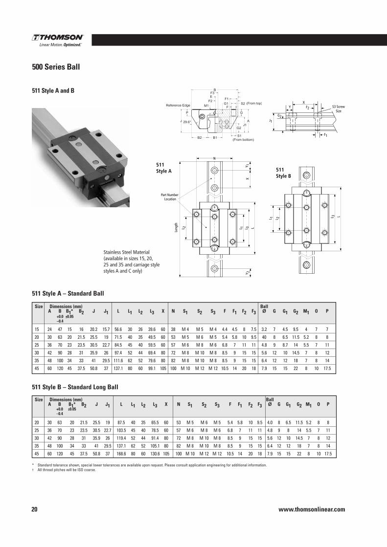
511 Style A and B
500 Series Ball
45
B2
M1
G1
G2 J 1
A
GOPJ
B
F3
F3
F F
E
B1
Leng
th
L 2 L 1 L 3 L
Y 2X
Y 1511Style A
L 1 L 2 L 3 L
511Style B
Reference Edge
Part Number Location
N
S2 (From top)
S1 (From bottom)
J1
YX
S3 ScrewSize
F1
F2
G2
* Standard tolerance shown, special lower tolerances are available upon request . Please consult application engineering for additional information .† All thread pitches will be ISO coarse .
511 Style A – Standard Ball
511 Style B – Standard Long Ball
Size Dimensions (mm) Ball A B B1* B2 J J1 L L1 L2 L3 X N S1 S2 S3 F F1 F2 F3 Ø G G1 G2 M1 O P +0 .0 ±0 .05 –0 .4
15 24 47 15 16 20 .2 15 .7 56 .6 30 26 39 .6 60 38 M 4 M 5 M 4 4 .4 4 .5 8 7 .5 3 .2 7 4 .5 9 .5 4 7 7
20 30 63 20 21 .5 25 .5 19 71 .5 40 35 49 .5 60 53 M 5 M 6 M 5 5 .4 5 .8 10 9 .5 40 8 6 .5 11 .5 5 .2 8 8
25 36 70 23 23 .5 30 .5 22 .7 84 .5 45 40 59 .5 60 57 M 6 M 8 M 6 6 .8 7 11 11 4 .8 9 8 .7 14 5 .5 7 11
30 42 90 28 31 35 .9 26 97 .4 52 44 69 .4 80 72 M 8 M 10 M 8 8 .5 9 15 15 5 .6 12 10 14 .5 7 8 12
35 48 100 34 33 41 29 .5 111 .6 62 52 79 .6 80 82 M 8 M 10 M 8 8 .5 9 15 15 6 .4 12 12 18 7 8 14
45 60 120 45 37 .5 50 .8 37 137 .1 80 60 99 .1 105 100 M 10 M 12 M 12 10 .5 14 20 18 7 .9 15 15 22 8 10 17 .5
Size Dimensions (mm) Ball A B B1* B2 J J1 L L1 L2 L3 X N S1 S2 S3 F F1 F2 F3 Ø G G1 G2 M1 O P +0 .0 ±0 .05 –0 .4
20 30 63 20 21 .5 25 .5 19 87 .5 40 35 65 .5 60 53 M 5 M 6 M 5 5 .4 5 .8 10 9 .5 4 .0 8 6 .5 11 .5 5 .2 8 8
25 36 70 23 23 .5 30 .5 22 .7 103 .5 45 40 78 .5 60 57 M 6 M 8 M 6 6 .8 7 11 11 4 .8 9 8 14 5 .5 7 11
30 42 90 28 31 35 .9 26 119 .4 52 44 91 .4 80 72 M 8 M 10 M 8 8 .5 9 15 15 5 .6 12 10 14 .5 7 8 12
35 48 100 34 33 41 29 .5 137 .1 62 52 105 .1 80 82 M 8 M 10 M 8 8 .5 9 15 15 6 .4 12 12 18 7 8 14
45 60 120 45 37 .5 50 .8 37 168 .6 80 60 130 .6 105 100 M 10 M 12 M 12 10 .5 14 20 18 7 .9 15 15 22 8 10 17 .5
500 Series Roller Profile Rail
400 Series Profile Rail
AccuM
iniM
icroGuide
Stainless Steel Material (available in sizes 15, 20,25 and 35 and carriage stylestyles A and C only)
Profile Rail Linear Guides
www.thomsonlinear.com 21
500 Series Ball
Profile Rail
500 Series Ball
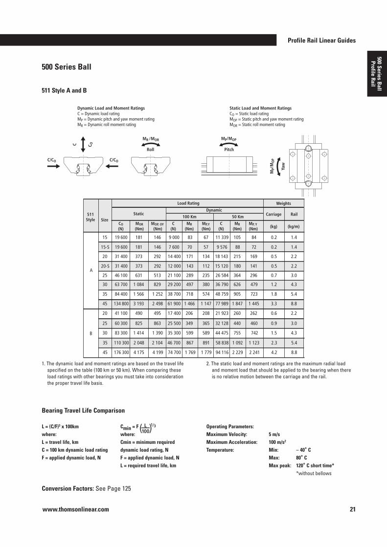
511 Style A and B
L = (C/F)3 x 100kmwhere:L = travel life, kmC = 100 km dynamic load ratingF = applied dynamic load, N
Cmin = F ( ) L 100
1⁄3
where:Cmin = minimum required dynamic load rating, NF = applied dynamic load, NL = required travel life, km
Operating Parameters:Maximum Velocity: 5 m/s Maximum Acceleration: 100 m/s2
Temperature: Min: – 40° C Max: 80° C Max peak: 120° C short time* *without bellows
Bearing Travel Life Comparison
Conversion Factors: See Page 125
19 600 181 146 9 000 83 67 15
511Style Size
MOP, OY (Nm)
MOR (Nm)
CO (N)
C (N)
MR (Nm)
MP,Y (Nm)
Static
11 339 105 84 0.2 1.4
(kg) (kg/m) C
(N) MR
(Nm) MP, Y (Nm)
Dynamic
100 Km 50 Km Carriage Rail
Load Rating Weights
31 400 373 292 14 400 171 13420 18 143 215 169 0.5 2.2
46 100 631 513 21 100 289 23525 26 584 364 296 0.7 3.0
63 700 1 084 829 29 200 497 38030 36 790 626 479 1.2 4.3
84 400 1 566 1 252 38 700 718 57435 48 759 905 723 1.8 5.4
134 800 3 193 2 498 61 900 1 466 1 14745 77 989 1 847 1 445 3.3 8.8
41 100 490 495 17 400 206 20820 21 923 260 262 0.6 2.2
60 300 825 863 25 500 349 36525
A
B
32 128 440 460 0.9 3.0
83 300 1 414 1 390 35 300 599 58930 44 475 755 742 1.5 4.3
2 048 2 104 46 700 867 89135 58 838 1 092 1 123 2.3 5.4
176 300 4 175 4 199 74 700 1 769 1 77945 94 116 2 229 2 241 4.2 8.8
19 600 181 146 7 600 70 5715-S 9 576 88 72 0.2 1.4
31 400 373 292 12 000 143 11220-S 15 120 180 141 0.5 2.2
110 300
1 . The dynamic load and moment ratings are based on the travel life specified on the table (100 km or 50 km) . When comparing these load ratings with other bearings you must take into consideration the proper travel life basis .
2 . The static load and moment ratings are the maximum radial load and moment load that should be applied to the bearing when there is no relative motion between the carriage and the rail .
www.thomsonlinear.com22
500 Series Ball Profile Rail Linear Guide
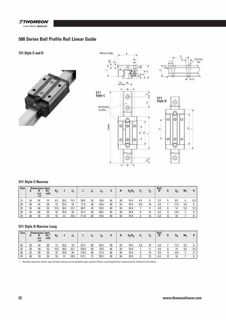
511 Style C and D
511Style C
511Style D
JM
1
O
B
G2 J 1
G
A
B1B2
Y 1X
L 1 L 3 LY 2
L 1 L 3 LLeng
th
Reference Edge
Part Number Location
N
N
S2
J1
F1
Y
XS3 Screw
SizeF2
G2
511 Style C Narrow
* Standard tolerance shown, special lower tolerances are available upon request . Please consult application engineering for additional information .
511 Style D Narrow Long
Size Dimensions (mm) Ball A B B1* B2 J J1 L L1 L3 X N S2/S3 F1 F2 Ø G G2 M1 O +0 .0 +0 .05 – 0 .4
15 24 34 15 9 .5 20 .2 15 .7 56 .6 26 39 .6 60 26 M 4 4 .5 8 3 .2 5 9 .5 4 5 .520 30 44 20 12 25 .5 19 71 .5 36 49 .5 60 32 M 5 5 .8 10 4 .0 7 11 .5 5 .2 625 36 48 23 12 .5 30 .5 22 .7 84 .5 35 59 .5 60 35 M 6 7 11 4 .8 9 14 5 .5 7 .530 42 60 28 16 35 .9 26 97 .4 40 69 .4 80 40 M 8 9 15 5 .6 11 14 .5 7 8 35 48 70 34 18 41 29 .5 111 .6 50 79 .6 80 50 M 8 9 15 6 .4 12 18 7 8
Size Dimensions (mm) Ball A B B1* B2 J J1 L L1 L3 X N S2/S3 F1 F2 Ø G G2 M1 O +0 .0 +0 .05 – 0 .4
20 30 44 20 12 25 .5 19 87 .5 50 65 .5 60 32 M 5 5 .8 10 4 .0 7 11 .5 5 .2 625 36 48 23 12 .5 30 .5 22 .7 103 .5 50 78 .5 60 35 M 6 7 11 4 .8 9 14 5 .5 7 .530 42 60 28 16 35 .9 26 119 .4 60 91 .4 80 40 M 8 9 15 5 .6 11 14 .5 7 835 48 70 34 18 41 29 .5 137 .1 72 105 .1 80 50 M 8 9 15 6 .4 12 18 7 8
Profile Rail Linear Guides
www.thomsonlinear.com 23
500 Series Ball
Profile Rail
500 Series Ball
511 Style C and D
L = (C/F)3 x 100 kmwhere:L = travel life, kmC = 100 km dynamic load ratingF = applied dynamic load, N
Cmin = F ( ) L 100
1⁄3
where:Cmin = minimum required dynamic load rating, NF = applied dynamic load, NL = required travel life, km
Operating Parameters:Maximum Velocity: 5 m/s Maximum Acceleration: 100 m/s2 Temperature: Min: – 40° C Max: 80° C Max peak: 120° C short time* *without bellows
Bearing Travel Life Comparison
Conversion Factors: See Page 125
C/CO C/CO
MR/MOR
Roll Pitch
MP/MOP
MP/
MO
P
Yaw
C C O
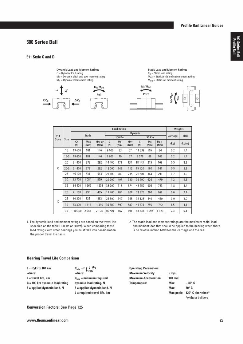
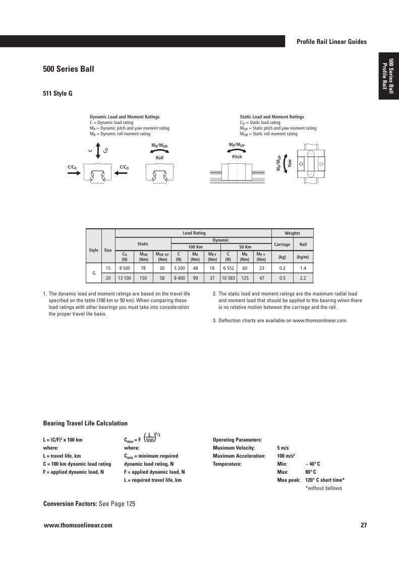
Dynamic Load and Moment Ratings C = Dynamic load rating MP = Dynamic pitch and yaw moment rating MR = Dynamic roll moment rating
Static Load and Moment Ratings CO = Static load rating MOP = Static pitch and yaw moment rating MOR = Static roll moment rating
1 . The dynamic load and moment ratings are based on the travel life specified on the table (100 km or 50 km) . When comparing these load ratings with other bearings you must take into consideration the proper travel life basis .
2 . The static load and moment ratings are the maximum radial load and moment load that should be applied to the bearing when there is no relative motion between the carriage and the rail .
19 600 181 146 9 000 83 67 15
511Style Size
MOP, OY (Nm)
MOR (Nm)
CO (N)
C (N)
MR (Nm)
MP,Y (Nm)
Static
11 339 105 84 0.2 1.4
(kg) (kg/m) C
(N) MR
(Nm) MP, Y (Nm)
Dynamic
100 Km 50 Km Carriage Rail
Load Rating Weights
19 600 181 146 7 600 70 5715-S 9 576 88 106 0.2 1.4
46 100 631 513 21 100 289 23525 26 584 364 296 0.7 3.0
63 700 1 084 829 29 200 497 38030 36 790 626 479 1.2 4.3
84 400 1 566 1 252 38 700 718 57435 48 759 905 723 1.8 5.4
41 100 490 495 17 400 206 20820 21 923 260 262 0.6 2.2
60 300 825 863 25 500 349 36525
C
D32 128 440 460 0.9 3.0
83 300 1 414 1 390 35 300 599 58930 44 475 755 742 1.5 4.3
110 300 2 048 2 104 46 700 867 89135 58 838 1 092 1 123 2.3 5.4
31 400 373 292 14 400 171 13420 18 143 215 169 0.5 2.2
31 400 373 292 12 000 143 11220-S 15 120 180 141 0.5 2.2
www.thomsonlinear.com24
500 Series Ball Profile Rail Linear Guide
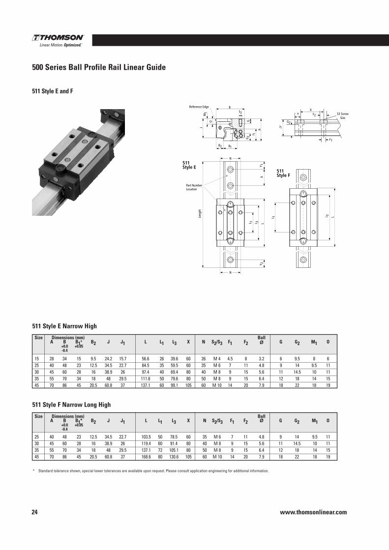
511 Style E and F
M1
J
O G
A
J 1
G2
B2 B1
B
Leng
th
Y 2
L 1 L 3 L
L 1 L 3 L
XY 1
511Style E
511Style F
Part Number Location
Reference Edge
J1
G2
YX
S3 ScrewSize
F1
F2
N
N
S2
511 Style E Narrow High
* Standard tolerance shown, special lower tolerances are available upon request . Please consult application engineering for additional information .
511 Style F Narrow Long High
Size Dimensions (mm) Ball A B B1* B2 J J1 L L1 L3 X N S2/S3 F1 F2 Ø G G2 M1 O +0 .0 +0 .05 -0 .4
15 28 34 15 9 .5 24 .2 15 .7 56 .6 26 39 .6 60 26 M 4 4 .5 8 3 .2 6 9 .5 8 625 40 48 23 12 .5 34 .5 22 .7 84 .5 35 59 .5 60 35 M 6 7 11 4 .8 9 14 9 .5 1130 45 60 28 16 38 .9 26 97 .4 40 69 .4 80 40 M 8 9 15 5 .6 11 14 .5 10 1135 55 70 34 18 48 29 .5 111 .6 50 79 .6 80 50 M 8 9 15 6 .4 12 18 14 1545 70 86 45 20 .5 60 .8 37 137 .1 60 99 .1 105 60 M 10 14 20 7 .9 18 22 18 19
Size Dimensions (mm) Ball A B B1* B2 J J1 L L1 L3 X N S2/S3 F1 F2 Ø G G2 M1 O +0 .0 +0 .05 -0 .4
25 40 48 23 12 .5 34 .5 22 .7 103 .5 50 78 .5 60 35 M 6 7 11 4 .8 9 14 9 .5 1130 45 60 28 16 38 .9 26 119 .4 60 91 .4 80 40 M 8 9 15 5 .6 11 14 .5 10 1135 55 70 34 18 48 29 .5 137 .1 72 105 .1 80 50 M 8 9 15 6 .4 12 18 14 1545 70 86 45 20 .5 60 .8 37 168 .6 80 130 .6 105 60 M 10 14 20 7 .9 18 22 18 19
Profile Rail Linear Guides
www.thomsonlinear.com 25
500 Series Ball
Profile Rail
500 Series Ball
511 Style E and F
Conversion Factors: See Page 125
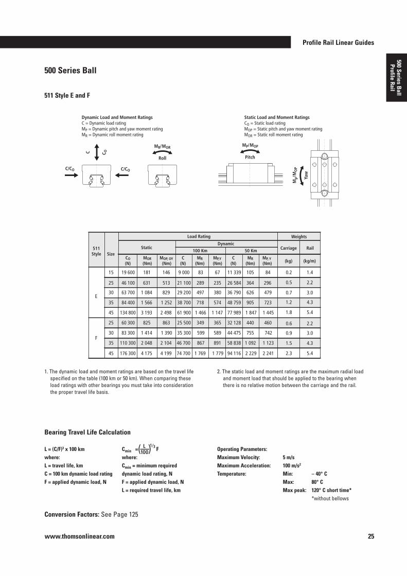
Dynamic Load and Moment Ratings C = Dynamic load rating MP = Dynamic pitch and yaw moment rating MR = Dynamic roll moment rating
Static Load and Moment Ratings CO = Static load rating MOP = Static pitch and yaw moment rating MOR = Static roll moment rating
C/CO C/CO
MR/MOR
Roll Pitch
MP/MOP
Mp/
MO
P
Yaw
C C O
L = (C/F)3 x 100 kmwhere:L = travel life, kmC = 100 km dynamic load ratingF = applied dynamic load, N
Cmin = F where:Cmin = minimum required dynamic load rating, NF = applied dynamic load, NL = required travel life, km
Operating Parameters:Maximum Velocity: 5 m/s Maximum Acceleration: 100 m/s2 Temperature: Min: – 40° C Max: 80° C Max peak: 120° C short time* *without bellows
Bearing Travel Life Calculation
( ) L 100
1⁄3
1 . The dynamic load and moment ratings are based on the travel life specified on the table (100 km or 50 km) . When comparing these load ratings with other bearings you must take into consideration the proper travel life basis .
2 . The static load and moment ratings are the maximum radial load and moment load that should be applied to the bearing when there is no relative motion between the carriage and the rail .
19 600 181 146 9 000 83 67 15
511Style Size
MOP, OY (Nm)
MOR (Nm)
CO (N)
C (N)
MR (Nm)
MP,Y (Nm)
Static
11 339 105 84 0.2 1.4
(kg) (kg/m) C
(N) MR
(Nm) MP, Y (Nm)
Dynamic
100 Km 50 Km Carriage Rail
Load Rating Weights
0.5 2.2 46 100 631 513 21 100 289 235 25 26 584 364 296
0.7 3.0 63 700 1 084 829 29 200 497 380 30 36 790 626 479
1.2 4.3 84 400 1 566 1 252 38 700 718 574 35 48 759 905 723
134 800 3 193 2 498 61 900 1 466 1 147 45 77 989 1 847 1 445 1.8 5.4
0.6 2.2 60 300 825 863 25 500 349 365 25
E
F
32 128 440 460
0.9 3.0 83 300 1 414 1 390 35 300 599 589 30 44 475 755 742
1.5 4.3 110 300 2 048 2 104 46 700 867 891 35 58 838 1 092 1 123
176 300 4 175 4 199 74 700 1 769 1 779 45 94 116 2 229 2 241 2.3 5.4
www.thomsonlinear.com26
500 Series Ball Profile Rail Linear Guide
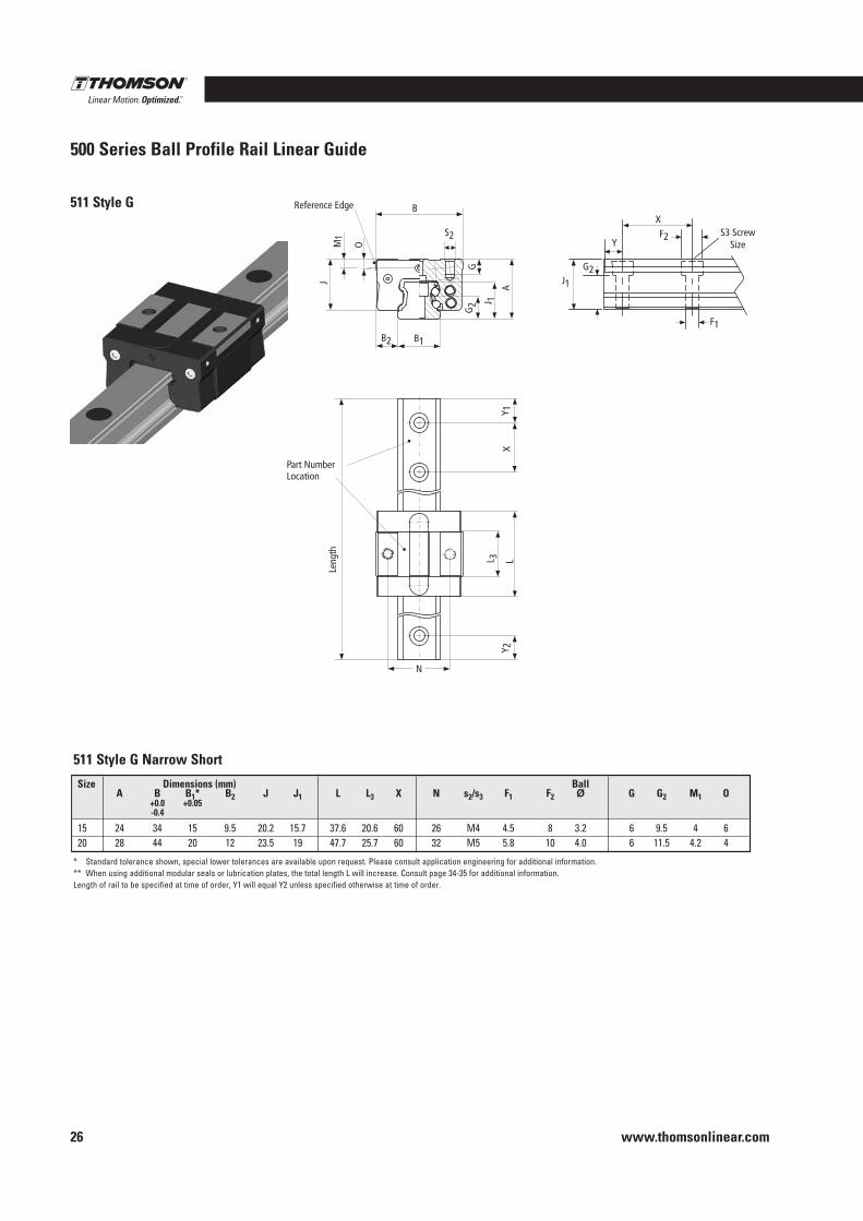
511 Style G
511 Style G Narrow Short
* Standard tolerance shown, special lower tolerances are available upon request . Please consult application engineering for additional information .** When using additional modular seals or lubrication plates, the total length L will increase . Consult page 34-35 for additional information .Length of rail to be specified at time of order, Y1 will equal Y2 unless specified otherwise at time of order .
J M
1
O
B
G2 J 1
G
A
B1 B2
Y 1
X
L 3
L Y 2
L 1
L 3
L
Leng
th
Reference Edge
Part Number Location
N
S2
J1
F1
Y
X S3 Screw
Size F2
G2
Size Dimensions (mm) Ball A B B1* B2 J J1 L L3 X N s2/s3 F1 F2 Ø G G2 M1 O +0 .0 +0 .05 -0 .4
15 24 34 15 9 .5 20 .2 15 .7 37 .6 20 .6 60 26 M4 4 .5 8 3 .2 6 9 .5 4 620 28 44 20 12 23 .5 19 47 .7 25 .7 60 32 M5 5 .8 10 4 .0 6 11 .5 4 .2 4
Profile Rail Linear Guides
www.thomsonlinear.com 27
500 Series Ball
Profile Rail
500 Series Ball
511 Style G
Conversion Factors: See Page 125
L = (C/F)3 x 100 kmwhere:L = travel life, kmC = 100 km dynamic load ratingF = applied dynamic load, N
Cmin = F where:Cmin = minimum required dynamic load rating, NF = applied dynamic load, NL = required travel life, km
Operating Parameters:Maximum Velocity: 5 m/s Maximum Acceleration: 100 m/s2 Temperature: Min: – 40° C Max: 80° C Max peak: 120° C short time* *without bellows
Bearing Travel Life Calculation
( ) L 100
1⁄3
1 . The dynamic load and moment ratings are based on the travel life specified on the table (100 km or 50 km) . When comparing these load ratings with other bearings you must take into consideration the proper travel life basis .
2 . The static load and moment ratings are the maximum radial load and moment load that should be applied to the bearing when there is no relative motion between the carriage and the rail .
3 . Deflection charts are available on www .thomsonlinear .com .
8 500 78 30 5 200 48 18 15
Style Size MOP, OY
(Nm) MOR (Nm)
CO (N)
C (N)
MR (Nm)
MP,Y (Nm)
Static
6 552 60 23 0.2 1.4
(kg) (kg/m) C
(N) MR
(Nm) MP, Y (Nm)
Dynamic
100 Km 50 Km Carriage Rail
Load Rating Weights
13 100 150 58 8 400 99 37 20 10 583 125 47 0.5 2.2 G
C/CO C/CO
MR/MOR
Roll Pitch
MP/MOP
MP/
MO
P
Yaw
C C O
Dynamic Load and Moment Ratings C = Dynamic load rating MP = Dynamic pitch and yaw moment rating MR = Dynamic roll moment rating
Static Load and Moment Ratings CO = Static load rating MOP = Static pitch and yaw moment rating MOR = Static roll moment rating
www.thomsonlinear.com28
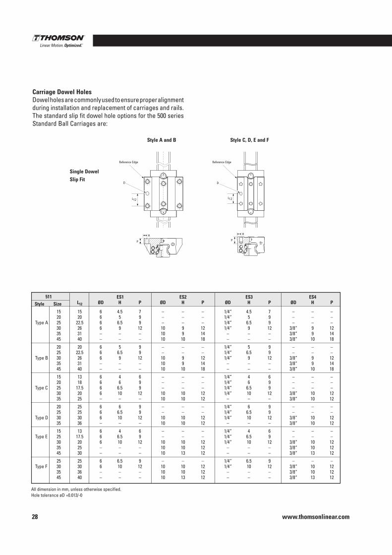
All dimension in mm, unless otherwise specified .Hole tolerance øD +0 .013/-0
Carriage Dowel HolesDowel holes are commonly used to ensure proper alignment during installation and replacement of carriages and rails . The standard slip fit dowel hole options for the 500 series Standard Ball Carriages are:
Single DowelSlip Fit
ES1 ES2 ES3 ES4 L12 ØD H P ØD H P ØD H P ØD H P
15 15 6 4 .5 7 – – – 1/4“ 4 .5 7 – – – 20 20 6 5 9 – – – 1/4“ 5 9 – – – Type A 25 22 .5 6 6 .5 9 – – – 1/4“ 6 .5 9 – – – 30 26 6 9 12 10 9 12 1/4“ 9 12 3/8“ 9 12 35 31 – – – 10 9 14 – – – 3/8“ 9 14 45 40 – – – 10 10 18 – – – 3/8“ 10 18
20 20 6 5 9 – – – 1/4“ 5 9 – – – 25 22 .5 6 6 .5 9 – – – 1/4“ 6 .5 9 – – – Type B 30 26 6 9 12 10 9 12 1/4“ 9 12 3/8“ 9 12 35 31 – – – 10 9 14 – – – 3/8“ 9 14 45 40 – – – 10 10 18 – – – 3/8“ 10 18
15 13 6 4 6 – – – 1/4“ 4 6 – – – 20 18 6 6 9 – – – 1/4“ 6 9 – – – Type C 25 17 .5 6 6 .5 9 – – – 1/4“ 6 .5 9 – – – 30 20 6 10 12 10 10 12 1/4“ 10 12 3/8“ 10 12 35 25 – – – 10 10 12 – – – 3/8“ 10 12
20 25 6 6 9 – – – 1/4“ 6 9 – – – 25 25 6 6 .5 9 – – – 1/4“ 6 .5 9 – – – Type D 30 30 6 10 12 10 10 12 1/4“ 10 12 3/8“ 10 12 35 36 – – – 10 10 12 – – – 3/8“ 10 12
15 13 6 4 6 – – – 1/4“ 4 6 – – – Type E 25 17 .5 6 6 .5 9 – – – 1/4“ 6 .5 9 – – – 30 20 6 10 12 10 10 12 1/4“ 10 12 3/8“ 10 12 35 25 – – – 10 10 12 – – – 3/8“ 10 12 45 30 – – – 10 13 12 – – – 3/8“ 13 12
25 25 6 6 .5 9 – – – 1/4“ 6 .5 9 – – – Type F 30 30 6 10 12 10 10 12 1/4“ 10 12 3/8“ 10 12 35 36 – – – 10 10 12 – – – 3/8“ 10 12 45 40 – – – 10 13 12 – – – 3/8“ 13 12
511Style Size
Style A and B Style C, D, E and F
Profile Rail Linear Guides
www.thomsonlinear.com 29
500 Series Ball
Profile Rail
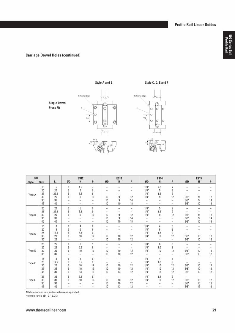
Carriage Dowel Holes (continued)
ES12 ES13 ES14 ES15 L12 ØD H P ØD H P ØD H P ØD H P
15 15 6 4 .5 7 – – – 1/4“ 4 .5 7 – – – 20 20 6 5 9 – – – 1/4“ 5 9 – – – Type A 25 22 .5 6 6 .5 9 – – – 1/4“ 6 .5 9 – – – 30 26 6 9 12 10 9 12 1/4“ 9 12 3/8“ 9 12 35 31 – – – 10 9 14 – – – 3/8“ 9 14 45 40 – – – 10 10 18 – – – 3/8“ 10 18
20 20 6 5 9 – – – 1/4“ 5 9 – – – 25 22 .5 6 6 .5 9 – – – 1/4“ 6 .5 9 – – – Type B 30 26 6 9 12 10 9 12 1/4“ 9 12 3/8“ 9 12 35 31 – – – 10 9 14 – – – 3/8“ 9 14 45 40 – – – 10 10 18 – – – 3/8“ 10 18
15 13 6 4 6 – – – 1/4“ 4 6 – – – 20 18 6 6 9 – – – 1/4“ 6 9 – – – Type C 25 17 .5 6 6 .5 9 – – – 1/4“ 6 .5 9 – – – 30 20 6 10 12 10 10 12 1/4“ 10 12 3/8“ 10 12 35 25 – – – 10 10 12 – – – 3/8“ 10 12
20 25 6 6 9 – – – 1/4“ 6 9 – – – 25 25 6 6 .5 9 – – – 1/4“ 6 .5 9 – – – Type D 30 30 6 10 12 10 10 12 1/4“ 10 12 3/8“ 10 12 35 36 – – – 10 10 12 – – – 3/8“ 10 12
15 13 6 4 6 – – – 1/4“ 4 6 – – – Type E 25 17 .5 6 6 .5 9 – – – 1/4“ 6 .5 9 – – – 30 20 6 10 12 10 10 12 1/4“ 10 12 3/8“ 10 12 35 25 6 10 12 10 10 12 1/4“ 10 12 3/8“ 10 12 45 30 6 13 12 10 13 12 1/4“ 13 12 3/8“ 13 12
25 25 6 6 .5 9 – – – 1/4“ 6 .5 9 – – – Type F 30 30 6 10 12 10 10 12 1/4“ 10 12 3/8“ 10 12 35 36 – – – 10 10 12 – – – 3/8“ 10 12 45 40 – – – 10 13 12 – – – 3/8“ 13 12
511Style Size
All dimension in mm, unless otherwise specified .Hole tolerance øD +0 / -0 .013
Single DowelPress Fit
Style A and B Style C, D, E and F
www.thomsonlinear.com30
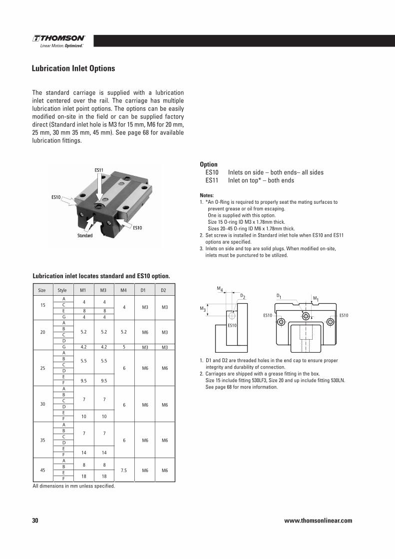
The standard carriage is supplied with a lubrication inlet centered over the rail . The carriage has multiple lubrication inlet point options . The options can be easily modified on-site in the field or can be supplied factory direct (Standard inlet hole is M3 for 15 mm, M6 for 20 mm, 25 mm, 30 mm 35 mm, 45 mm) . See page 68 for available lubrication fittings .
Option ES10 Inlets on side – both ends– all sides ES11 Inlet on top* – both ends
Notes:1 . * An O-Ring is required to properly seat the mating surfaces to
prevent grease or oil from escaping . One is supplied with this option . Size 15 O-ring ID M3 x 1 .78mm thick . Sizes 20–45 O-ring ID M6 x 1 .78mm thick .
2 . Set screw is installed in Standard inlet hole when ES10 and ES11 options are specified .
3 . Inlets on side and top are solid plugs . When modified on-site, inlets must be punctured to be utilized .
Size
15 8 8
M3 M3
M6 M3
M6 M6
4 4
4 4
4
5.2 5.2 5.2
M3 M3 4.2 4.2 5
5.5 5.5
6
M6 M6 6
M6 M6 6
M6 M6 7.5
9.5 9.5
7 7
10 10
7 7
14 14
18 18
8 8
20
25
30
35
45
Style M1 M3 M4 D1 D2
A C E G A B C D G A B C D E F A B C D E F A B C D E F A B E F
D1
ES10
D2
M4
M1
ES10ES10
M3
All dimensions in mm unless specified .
1 . D1 and D2 are threaded holes in the end cap to ensure proper integrity and durability of connection .
2 . Carriages are shipped with a grease fitting in the box . Size 15 include fitting 530LF3, Size 20 and up include fitting 530LN . See page 68 for more information .
Lubrication inlet locates standard and ES10 option .
Lubrication Inlet Options
Profile Rail Linear Guides
www.thomsonlinear.com 31
500 Series Ball
Profile Rail
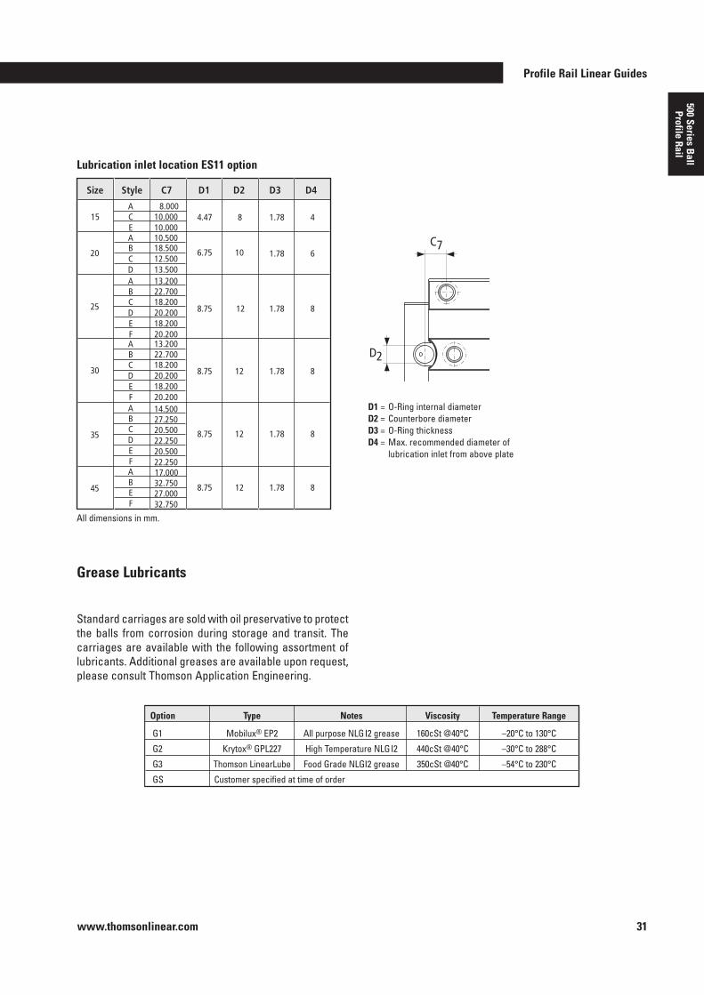
C7
D2
D1 = O-Ring internal diameterD2 = Counterbore diameterD3 = O-Ring thicknessD4 = Max . recommended diameter of
lubrication inlet from above plate
Size
A 15
E 1.78 4
1.78 6
1.78 8
4.47 8
6.75 10
12
1.78 8 12
1.78 8 12
1.78 8 12
8.75
8.75
8.75
8.75
A
20
25
30
35
45
C D A B
B
C
C D E F A B C D E F
Style C7 D1 D2 D3 D4
A B C D E F A B E F
8.000
10.000 10.500
12.500 13.500 13.200 22.700
18.500
10.000
18.200 20.200 18.200 20.200 13.200 22.700 18.200 20.200 18.200 20.200 14.500 27.250 20.500 22.250 20.500 22.250 17.000 32.750 27.000 32.750
All dimensions in mm .
Lubrication inlet location ES11 option
Standard carriages are sold with oil preservative to protect the balls from corrosion during storage and transit . The carriages are available with the following assortment of lubricants . Additional greases are available upon request, please consult Thomson Application Engineering .
Option Type Notes Viscosity Temperature Range
G1 Mobilux® EP2 All purpose NLGI2 grease 160cSt @40°C –20°C to 130°C
G2 Krytox® GPL227 High Temperature NLGI2 440cSt @40°C –30°C to 288°C
G3 Thomson LinearLube Food Grade NLGI2 grease 350cSt @40°C –54°C to 230°C
GS Customer specified at time of order
Grease Lubricants
www.thomsonlinear.com32
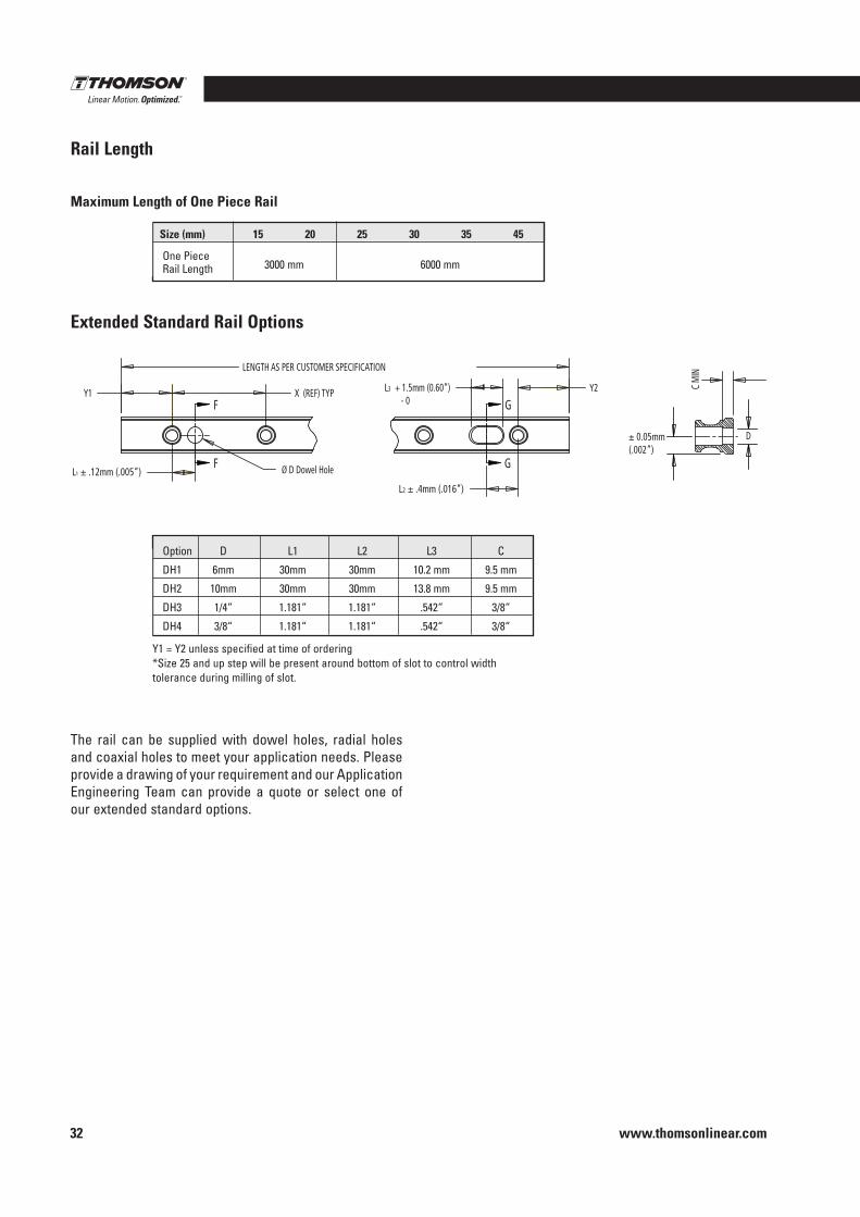
L3 + 1.5mm (0.60”) - 0
Ø D Dowel Hole
LENGTH AS PER CUSTOMER SPECIFICATION
Y1 X (REF) TYP
L1 ± .12mm (.005”)
Y2
L2 ± .4mm (.016”)
D
C M
IN
F
F
G
G
± 0.05mm (.002”)
Y1 = Y2 unless specified at time of ordering*Size 25 and up step will be present around bottom of slot to control width tolerance during milling of slot .
The rail can be supplied with dowel holes, radial holes and coaxial holes to meet your application needs . Please provide a drawing of your requirement and our Application Engineering Team can provide a quote or select one of our extended standard options .
Maximum Length of One Piece Rail
Rail Length
Extended Standard Rail Options
Size (mm) 15 20 25 30 35 45
One Piece Rail Length 3000 mm 6000 mm
Option D L1 L2 L3 C
DH1 6mm 30mm 30mm 10 .2 mm 9 .5 mm
DH2 10mm 30mm 30mm 13 .8 mm 9 .5 mm
DH3 1/4“ 1 .181“ 1 .181“ .542“ 3/8“
DH4 3/8“ 1 .181“ 1 .181“ .542“ 3/8“
Profile Rail Linear Guides
www.thomsonlinear.com 33
500 Series Ball
Profile Rail
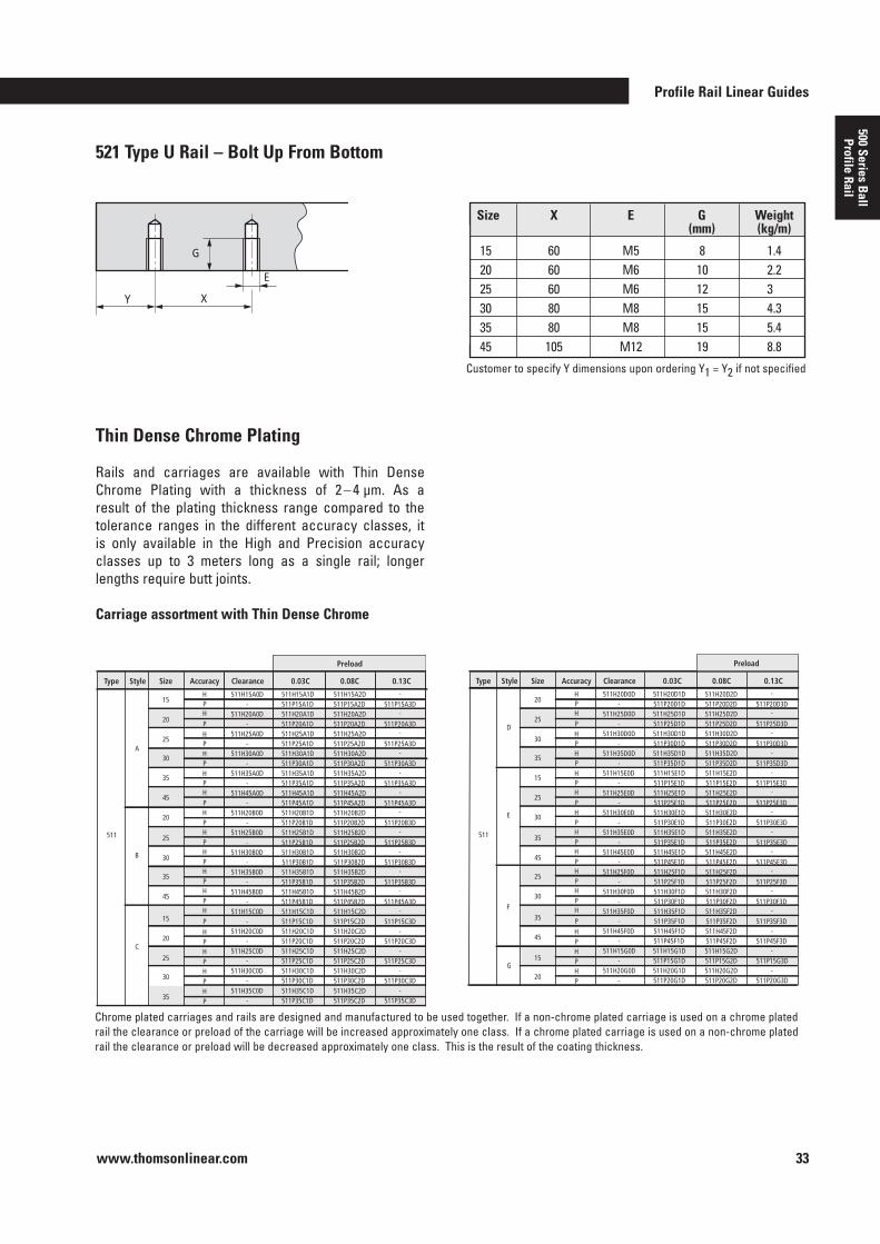
521 Type U Rail – Bolt Up From Bottom
Y X
E
G
Thin Dense Chrome Plating
Rails and carriages are available with Thin Dense Chrome Plating with a thickness of 2 – 4 µm . As a result of the plating thickness range compared to the tolerance ranges in the different accuracy classes, it is only available in the High and Precision accuracy classes up to 3 meters long as a single rail; longer lengths require butt joints .
Carriage assortment with Thin Dense Chrome
Size X E G Weight (mm) (kg/m)
15 60 M5 8 1 .420 60 M6 10 2 .225 60 M6 12 330 80 M8 15 4 .335 80 M8 15 5 .445 105 M12 19 8 .8
Customer to specify Y dimensions upon ordering Y1 = Y2 if not specified
15 H P H P H P H P H P H P H P H P H P H P H P H
P H P H P H P
511H15A0D 511H15A1D - 511P15A1D
511H20A0D 511H20A1D
511H25A0D 511H25A1D - 511P25A1D
- 511P20A1D
511H30A0D 511H30A1D
- 511P35A1D
- 511P30A1D 511H35A0D 511H35A1D
511H45A0D 511H45A1D
511H20B0D 511H20B1D - 511P20B1D
- 511P45A1D
511H25B0D 511H25B1D - 511P25B1D
- 511P30B1D 511H30B0D 511H30B1D
511H35B0D 511H35B1D - 511P35B1D
511H45B0D 511H45B1D - 511P45B1D
511H15C0D 511H15C1D - 511P15C1D
511H20C0D 511H20C1D - 511P20C1D
511H25C0D 511H25C1D - 511P25C1D
511H30C0D 511H30C1D - 511P30C1D
511H15A2D 511P15A2D 511H20A2D
511H25A2D 511P25A2D
511P20A2D
511H30A2D
511P35A2D
511P30A2D 511H35A2D
511H45A2D
511H20B2D 511P20B2D
511P45A2D
511H25B2D 511P25B2D
511P30B2D 511H30B2D
511H35B2D 511P35B2D 511H45B2D 511P45B2D 511H15C2D 511P15C2D 511H20C2D 511P20C2D 511H25C2D 511P25C2D 511H30C2D 511P30C2D
-
511P15A3D -
-
511P25A3D
511P20A3D
-
511P35A3D
511P30A3D -
-
-
511P20B3D
511P45A3D
-
511P25B3D
511P30B3D
-
-
511P35B3D -
511P45A3D -
511P15C3D -
511P20C3D -
511P25C3D -
511P30C3D
A
B
C
Type Style Size Accuracy Clearance 0.03C 0.08C
Preload
0.13C
20
25
30
15
20
25
30
HP
511H35C0D 511H35C1D- 511P35C1D
511H35C2D511P35C2D
-511P35C3D35
35
45
20
25 511
30
35
45
20 H P H P H P H P H P H P H P H P H P H P H P H
P H P H P H P
511H20D0D 511H20D1D - 511P20D1D
511H25D0D 511H25D1D
511H30D0D 511H30D1D - 511P30D1D
- 511P25D1D
511H35D0D 511H35D1D
- 511P15E1D
- 511P35D1D 511H15E0D 511H15E1D
511H25E0D 511H25E1D
511H30E0D 511H30E1D - 511P30E1D
- 511P25E1D
511H35E0D 511H35E1D - 511P35E1D
- 511P45E1D 511H45E0D 511H45E1D
511H25F0D 511H25F1D - 511P25F1D
511H30F0D 511H30F1D - 511P30F1D
511H35F0D 511H35F1D - 511P35F1D
511H45F0D 511H45F1D - 511P45F1D
511H15G0D 511H15G1D - 511P15G1D
511H20G0D 511H20G1D - 511P20G1D
511H20D2D 511P20D2D 511H25D2D
511H30D2D 511P30D2D
511P25D2D
511H35D2D
511P15E2D
511P35D2D 511H15E2D
511H25E2D
511H30E2D 511P30E2D
511P25E2D
511H35E2D 511P35E2D
511P45E2D 511H45E2D
511H25F2D 511P25F2D 511H30F2D 511P30F2D 511H35F2D 511P35F2D 511H45F2D 511P45F2D 511H15G2D 511P15G2D 511H20G2D 511P20G2D
-
511P20D3D -
-
511P30D3D
511P25D3D
-
511P15E3D
511P35D3D -
-
-
511P30E3D
511P25E3D
-
511P35E3D
511P45E3D
-
-
511P25F3D -
511P30F3D -
511P35F3D -
511P45F3D -
511P15G3D -
511P20G3D
D
E
F
G
Type Style Size Accuracy Clearance 0.03C 0.08C
Preload
0.13C
25
30
35
35
45
15
20
15
25
30
35 511
45
25
30
Chrome plated carriages and rails are designed and manufactured to be used together . If a non-chrome plated carriage is used on a chrome plated rail the clearance or preload of the carriage will be increased approximately one class . If a chrome plated carriage is used on a non-chrome plated rail the clearance or preload will be decreased approximately one class . This is the result of the coating thickness .
www.thomsonlinear.com34
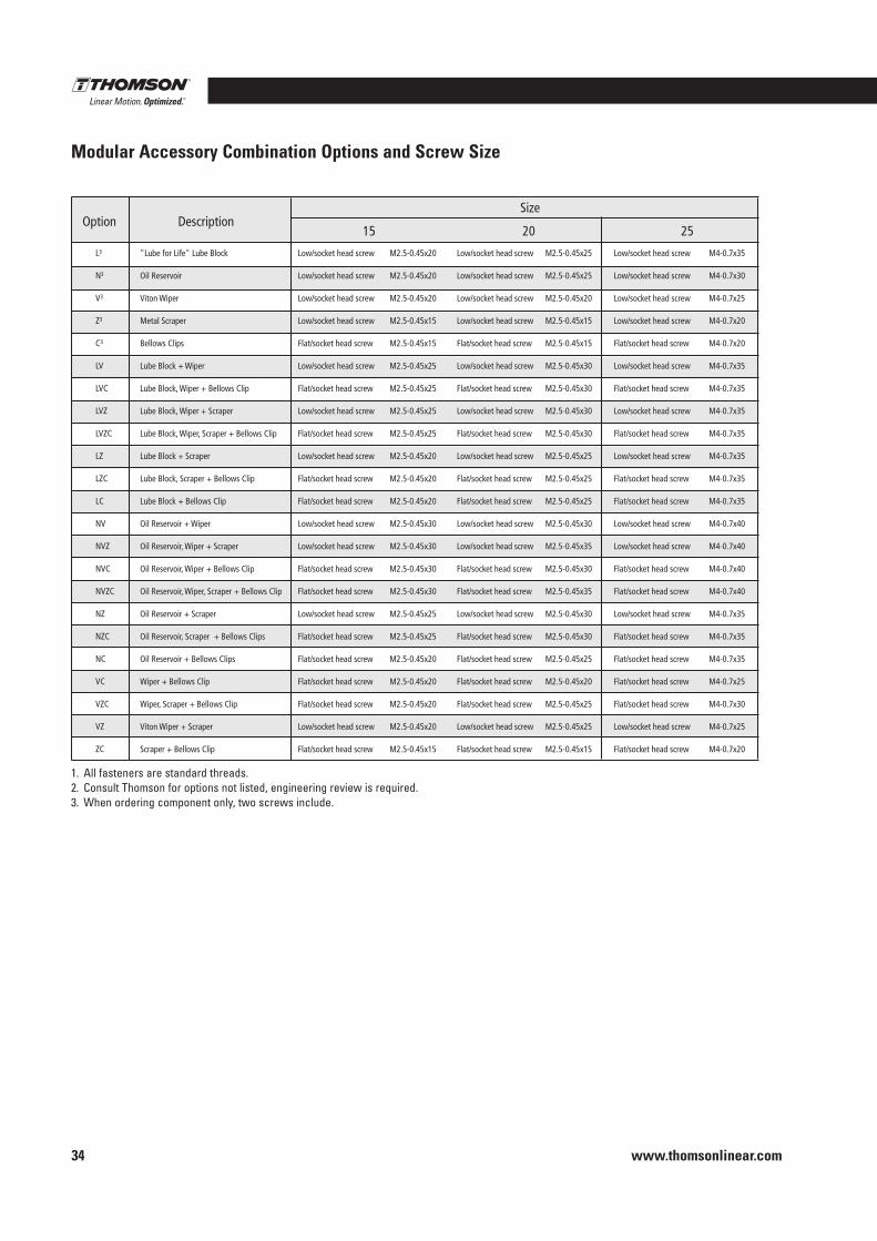
Modular Accessory Combination Options and Screw Size
M4x0.7-45
M4x0.7-35
M4x0.7-30
M4x0.7-30
M4x0.7-25
M4x0.7-25
M4x0.7-45
M4x0.7-45
M4x0.7-45
M4x0.7-45
M4x0.7-45
M4x0.7-45
M4x0.7-45
M4x0.7-45
M4x0.7-45
M4x0.7-45
M4x0.7-50
M4x0.7-40
M4x0.7-40
M4x0.7-40
M4x0.7-30
M4x0.7-30
M4x0.7-30
M4x0.7-30
M4x0.7-25
Low/socket head screw
Low/socket head screw
Low/socket head screw
Low/socket head screw
Low/socket head screw
Flat/socket head screw
Low/socket head screw
Flat/socket head screw
Low/socket head screw
Flat/socket head screw
Low/socket head screw
Flat/socket head screw
Flat/socket head screw
Low/socket head screw
Low/socket head screw
Flat/socket head screw
Flat/socket head screw
Low/socket head screw
Flat/socket head screw
Flat/socket head screw
Flat/socket head screw
Low/socket head screw
Flat/socket head screw
Low/socket head screw
Flat/socket head screw
Low/socket head screw
Low/socket head screw
Low/socket head screw
Low/socket head screw
Low/socket head screw
Flat/socket head screw
Low/socket head screw
Flat/socket head screw
Low/socket head screw
Flat/socket head screw
Low/socket head screw
Flat/socket head screw
Flat/socket head screw
Low/socket head screw
Low/socket head screw
Flat/socket head screw
Flat/socket head screw
Low/socket head screw
Flat/socket head screw
Flat/socket head screw
Flat/socket head screw
Low/socket head screw
Flat/socket head screw
Low/socket head screw
Flat/socket head screw
M5x0.8-50
M5x0.8-45
M5x0.8-35
M5x0.8-35
M5x0.8-30
M5x0.8-30
M5x0.8-50
M5x0.8-50
M5x0.8-50
M5x0.8-54
M5x0.8-50
M5x0.8-54
M5x0.8-50
M5x0.8-50
M5x0.8-55
M5x0.8-54
M5x0.8-54
M5x0.8-45
M5x0.8-50
M5x0.8-50
M5x0.8-34
M5x0.8-35
M5x0.8-35
M5x0.8-35
M5x0.8-30
M4x0.7-40
M4x0.7-30
M4x0.7-25
M4x0.7-25
M4x0.7-20
M4x0.7-20
M4x0.7-40
M4x0.7-40
M4x0.7-40
M4x0.7-40
M4x0.7-40
M4x0.7-40
M4x0.7-40
M4x0.7-40
M4x0.7-40
M4x0.7-40
M4x0.7-45
M4x0.7-35
M4x0.7-35
M4x0.7-35
M4x0.7-25
M4x0.7-25
M4x0.7-30
M4x0.7-25
M4x0.7-20
Low/socket head screw
Low/socket head screw
Low/socket head screw
Low/socket head screw
Low/socket head screw
Flat/socket head screw
Low/socket head screw
Flat/socket head screw
Low/socket head screw
Flat/socket head screw
Low/socket head screw
Flat/socket head screw
Flat/socket head screw
Low/socket head screw
Low/socket head screw
Flat/socket head screw
Flat/socket head screw
Low/socket head screw
Flat/socket head screw
Flat/socket head screw
Flat/socket head screw
Low/socket head screw
Flat/socket head screw
Low/socket head screw
Flat/socket head screw
M4x0.7-35
M4x0.7-30
M4x0.7-25
M4x0.7-25
M4x0.7-20
M4x0.7-20
M4x0.7-35
M4x0.7-35
M4x0.7-35
M4x0.7-40
M4x0.7-35
M4x0.7-40
M4x0.7-35
M4x0.7-40
M4x0.7-40
M4x0.7-40
M4x0.7-40
M4x0.7-35
M4x0.7-35
M4x0.7-32
M4x0.7-25
M4x0.7-25
M4x0.7-30
M4x0.7-25
M4x0.7-20
Low/socket head screw
Low/socket head screw
Low/socket head screw
Low/socket head screw
Low/socket head screw
Flat/socket head screw
Low/socket head screw
Flat/socket head screw
Low/socket head screw
Flat/socket head screw
Low/socket head screw
Flat/socket head screw
Flat/socket head screw
Low/socket head screw
Low/socket head screw
Flat/socket head screw
Flat/socket head screw
Low/socket head screw
Flat/socket head screw
Flat/socket head screw
Flat/socket head screw
Low/socket head screw
Flat/socket head screw
Low/socket head screw
Flat/socket head screw
M2.5x0.45-25
M2.5x0.45-25
M2.5x0.45-20
M2.5x0.45-20
M2.5x0.45-16
M2.5x0.45-16
M2.5x0.45-28
M2.5x0.45-28
M2.5x0.45-32
M2.5x0.45-32
M2.5x0.45-25
M2.5x0.45-25
M2.5x0.45-25
M2.5x0.45-32
M2.5x0.45-34
M2.5x0.45-32
M2.5x0.45-34
M2.5x0.45-28
M2.5x0.45-28
M2.5x0.45-25
M2.5x0.45-20
M2.5x0.45-25
M2.5x0.45-25
M2.5x0.45-25
M2.5x0.45-16
Low/socket head screw
Low/socket head screw
Low/socket head screw
Low/socket head screw
Low/socket head screw
Flat/socket head screw
Low/socket head screw
Flat/socket head screw
Low/socket head screw
Flat/socket head screw
Low/socket head screw
Flat/socket head screw
Flat/socket head screw
Low/socket head screw
Low/socket head screw
Flat/socket head screw
Flat/socket head screw
Low/socket head screw
Flat/socket head screw
Flat/socket head screw
Flat/socket head screw
Low/socket head screw
Flat/socket head screw
Low/socket head screw
Flat/socket head screw
M2.5x0.45-20
M2.5x0.45-20
M2.5x0.45-20
M2.5x0.45-20
M2.5x0.45-16
M2.5x0.45-16
M2.5x0.45-25
M2.5x0.45-25
M2.5x0.45-28
M2.5x0.45-28
M2.5x0.45-20
M2.5x0.45-20
M2.5x0.45-20
M2.5x0.45-30
M2.5x0.45-30
M2.5x0.45-30
M2.5x0.45-30
M2.5x0.45-25
M2.5x0.45-25
M2.5x0.45-20
M2.5x0.45-20
M2.5x0.45-20
M2.5x0.45-20
M2.5x0.45-20
M2.5x0.45-16
Low/socket head screw
Low/socket head screw
Low/socket head screw
Low/socket head screw
Low/socket head screw
Flat/socket head screw
Low/socket head screw
Flat/socket head screw
Low/socket head screw
Flat/socket head screw
Low/socket head screw
Flat/socket head screw
Flat/socket head screw
Low/socket head screw
Low/socket head screw
Flat/socket head screw
Flat/socket head screw
Low/socket head screw
Flat/socket head screw
Flat/socket head screw
Flat/socket head screw
Low/socket head screw
Flat/socket head screw
Low/socket head screw
Flat/socket head screw
"Lube for Life" Lube Block
Oil Reservoir
Rubber Wiper
Viton Wiper
Metal Scraper
Bellows Clips
Lube Block + Wiper
Lube Block, Wiper + Bellows Clip
Lube Block, Wiper + Scraper
Lube Block, Wiper, Scraper + Bellows Clip
Lube Block + Scraper
Lube Block, Scraper + Bellows Clip
Lube Block + Bellows Clip
Oil Rerservoir + Wiper
Oil Rerservoir, Wiper + Scraper
Oil Rerservoir, Wiper + Bellows Clip
Oil Rerservoir, Wiper, Scraper + Bellows Clip
Oil Rerservoir + Scraper
Oil Rerservoi, Scraper + Bellows Clips
Oil Rerservoir + Bellows Clips
Wiper + Bellows Clip
Wiper + Scraper
Wiper, Scraper + Bellows Clip
Viton Wiper + Scraper
Scraper + Bellows Clip
L
N
W
V
Z
C
LW
LWC
LWZ
LWZC
LZ
LZC
LC
NW
NWZ
NWC
NWZC
NZ
NZC
NC
WC
WZ
WZC
VZ
ZC
15 Description Option 20 25 30 35 45
M4-0.7x35
M4-0.7x30
M4-0.7x25
M4-0.7x20
M4-0.7x20
M4-0.7x35
M4-0.7x35
M4-0.7x35
M4-0.7x35
M4-0.7x35
M4-0.7x35
M4-0.7x35
M4-0.7x40
M4-0.7x40
M4-0.7x40
M4-0.7x40
M4-0.7x35
M4-0.7x35
M4-0.7x35
M4-0.7x25
M4-0.7x30
M4-0.7x25
M4-0.7x20
Low/socket head screw
Low/socket head screw
Low/socket head screw
Low/socket head screw
Flat/socket head screw
Low/socket head screw
Flat/socket head screw
Low/socket head screw
Flat/socket head screw
Low/socket head screw
Flat/socket head screw
Flat/socket head screw
Low/socket head screw
Low/socket head screw
Flat/socket head screw
Flat/socket head screw
Low/socket head screw
Flat/socket head screw
Flat/socket head screw
Flat/socket head screw
Flat/socket head screw
Low/socket head screw
Flat/socket head screw
M2.5-0.45x25
M2.5-0.45x25
M2.5-0.45x20
M2.5-0.45x15
M2.5-0.45x15
M2.5-0.45x30
M2.5-0.45x30
M2.5-0.45x30
M2.5-0.45x30
M2.5-0.45x25
M2.5-0.45x25
M2.5-0.45x25
M2.5-0.45x30
M2.5-0.45x35
M2.5-0.45x30
M2.5-0.45x35
M2.5-0.45x30
M2.5-0.45x30
M2.5-0.45x25
M2.5-0.45x20
M2.5-0.45x25
M2.5-0.45x25
M2.5-0.45x15
Low/socket head screw
Low/socket head screw
Low/socket head screw
Low/socket head screw
Flat/socket head screw
Low/socket head screw
Flat/socket head screw
Low/socket head screw
Flat/socket head screw
Low/socket head screw
Flat/socket head screw
Flat/socket head screw
Low/socket head screw
Low/socket head screw
Flat/socket head screw
Flat/socket head screw
Low/socket head screw
Flat/socket head screw
Flat/socket head screw
Flat/socket head screw
Flat/socket head screw
Low/socket head screw
Flat/socket head screw
M2.5-0.45x20
M2.5-0.45x20
M2.5-0.45x20
M2.5-0.45x15
M2.5-0.45x15
M2.5-0.45x25
M2.5-0.45x25
M2.5-0.45x25
M2.5-0.45x25
M2.5-0.45x20
M2.5-0.45x20
M2.5-0.45x20
M2.5-0.45x30
M2.5-0.45x30
M2.5-0.45x30
M2.5-0.45x30
M2.5-0.45x25
M2.5-0.45x25
M2.5-0.45x20
M2.5-0.45x20
M2.5-0.45x20
M2.5-0.45x20
M2.5-0.45x15
Low/socket head screw
Low/socket head screw
Low/socket head screw
Low/socket head screw
Flat/socket head screw
Low/socket head screw
Flat/socket head screw
Low/socket head screw
Flat/socket head screw
Low/socket head screw
Flat/socket head screw
Flat/socket head screw
Low/socket head screw
Low/socket head screw
Flat/socket head screw
Flat/socket head screw
Low/socket head screw
Flat/socket head screw
Flat/socket head screw
Flat/socket head screw
Flat/socket head screw
Low/socket head screw
Flat/socket head screw
"Lube for Life" Lube Block
Oil Reservoir
Viton Wiper
Metal Scraper
Bellows Clips
Lube Block + Wiper
Lube Block, Wiper + Bellows Clip
Lube Block, Wiper + Scraper
Lube Block, Wiper, Scraper + Bellows Clip
Lube Block + Scraper
Lube Block, Scraper + Bellows Clip
Lube Block + Bellows Clip
Oil Reservoir + Wiper
Oil Reservoir, Wiper + Scraper
Oil Reservoir, Wiper + Bellows Clip
Oil Reservoir, Wiper, Scraper + Bellows Clip
Oil Reservoir + Scraper
Oil Reservoir, Scraper + Bellows Clips
Oil Reservoir + Bellows Clips
Wiper + Bellows Clip
Wiper, Scraper + Bellows Clip
Viton Wiper + Scraper
Scraper + Bellows Clip
L3
N3
V3
Z3
C3
LV
LVC
LVZ
LVZC
LZ
LZC
LC
NV
NVZ
NVC
NVZC
NZ
NZC
NC
VC
VZC
VZ
ZC
15 Description Option
20 25
M4-0.7x45
M4-0.7x35
M4-0.7x30
M4-0.7x25
M4-0.7x25
M4-0.7x45
M4-0.7x45
M4-0.7x45
M4-0.7x45
M4-0.7x45
M4-0.7x45
M4-0.7x45
M4-0.7x45
M4-0.7x45
M4-0.7x45
M4-0.7x50
M4-0.7x40
M4-0.7x40
M4-0.7x40
M4-0.7x30
M4-0.7x30
M4-0.7x30
M4-0.7x25
Low/socket head screw
Low/socket head screw
Low/socket head screw
Low/socket head screw
Flat/socket head screw
Low/socket head screw
Flat/socket head screw
Low/socket head screw
Flat/socket head screw
Low/socket head screw
Flat/socket head screw
Flat/socket head screw
Low/socket head screw
Low/socket head screw
Flat/socket head screw
Flat/socket head screw
Low/socket head screw
Flat/socket head screw
Flat/socket head screw
Flat/socket head screw
Flat/socket head screw
Low/socket head screw
Flat/socket head screw
Low/socket head screw
Low/socket head screw
Low/socket head screw
Low/socket head screw
Flat/socket head screw
Low/socket head screw
Flat/socket head screw
Low/socket head screw
Flat/socket head screw
Low/socket head screw
Flat/socket head screw
Flat/socket head screw
Low/socket head screw
Low/socket head screw
Flat/socket head screw
Flat/socket head screw
Low/socket head screw
Flat/socket head screw
Flat/socket head screw
Flat/socket head screw
Flat/socket head screw
Low/socket head screw
Flat/socket head screw
M5-0.8x50
M5-0.8x45
M5-0.8x35
M5-0.8x30
M5-0.8x30
M5-0.8x50
M5-0.8x50
M5-0.8x50
M5-0.8x50
M5-0.8x50
M5-0.8x50
M5-0.8x50
M5-0.8x50
M5-0.8x55
M5-0.8x55
M5-0.8x55
M5-0.8x45
M5-0.8x50
M5-0.8x50
M5-0.8x35
M5-0.8x35
M5-0.8x35
M5-0.8x30
M4-0.7x40
M4-0.7x30
M4-0.7x25
M4-0.7x20
M4-0.7x20
M4-0.7x40
M4-0.7x40
M4-0.7x40
M4-0.7x40
M4-0.7x40
M4-0.7x40
M4-0.7x40
M4-0.7x40
M4-0.7x40
M4-0.7x40
M4-0.7x45
M4-0.7x35
M4-0.7x35
M4-0.7x35
M4-0.7x25
M4-0.7x30
M4-0.7x25
M4-0.7x20
Low/socket head screw
Low/socket head screw
Low/socket head screw
Low/socket head screw
Flat/socket head screw
Low/socket head screw
Flat/socket head screw
Low/socket head screw
Flat/socket head screw
Low/socket head screw
Flat/socket head screw
Flat/socket head screw
Low/socket head screw
Low/socket head screw
Flat/socket head screw
Flat/socket head screw
Low/socket head screw
Flat/socket head screw
Flat/socket head screw
Flat/socket head screw
Flat/socket head screw
Low/socket head screw
Flat/socket head screw
"Lube for Life" Lube Block
Oil Reservoir
Viton Wiper
Metal Scraper
Bellows Clips
Lube Block + Wiper
Lube Block, Wiper + Bellows Clip
Lube Block, Wiper + Scraper
Lube Block, Wiper, Scraper + Bellows Clip
Lube Block + Scraper
Lube Block, Scraper + Bellows Clip
Lube Block + Bellows Clip
Oil Reservoir + Wiper
Oil Reservoir, Wiper + Scraper
Oil Reservoir, Wiper + Bellows Clip
Oil Reservoir, Wiper, Scraper + Bellows Clip
Oil Reservoir + Scraper
Oil Reservoir, Scraper + Bellows Clips
Oil Reservoir + Bellows Clips
Wiper + Bellows Clip
Wiper, Scraper + Bellows Clip
Wiper + Scraper
Scraper + Bellows Clip
L
N
V
Z
C
LV
LVC
LVZ
LVZC
LZ
LZC
LC
NV
NVZ
NVC
NVZC
NZ
NZC
NC
VC
VZC
VZ
ZC
Description Option 30 35
Size Size
45
1 . All fasteners are standard threads .2 . Consult Thomson for options not listed, engineering review is required .3 . When ordering component only, two screws include .
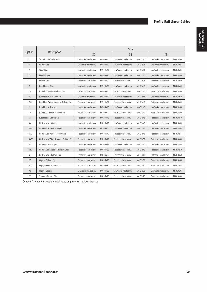
Profile Rail Linear Guides
www.thomsonlinear.com 35
500 Series Ball
Profile Rail
M4x0.7-45
M4x0.7-35
M4x0.7-30
M4x0.7-30
M4x0.7-25
M4x0.7-25
M4x0.7-45
M4x0.7-45
M4x0.7-45
M4x0.7-45
M4x0.7-45
M4x0.7-45
M4x0.7-45
M4x0.7-45
M4x0.7-45
M4x0.7-45
M4x0.7-50
M4x0.7-40
M4x0.7-40
M4x0.7-40
M4x0.7-30
M4x0.7-30
M4x0.7-30
M4x0.7-30
M4x0.7-25
Low/socket head screw
Low/socket head screw
Low/socket head screw
Low/socket head screw
Low/socket head screw
Flat/socket head screw
Low/socket head screw
Flat/socket head screw
Low/socket head screw
Flat/socket head screw
Low/socket head screw
Flat/socket head screw
Flat/socket head screw
Low/socket head screw
Low/socket head screw
Flat/socket head screw
Flat/socket head screw
Low/socket head screw
Flat/socket head screw
Flat/socket head screw
Flat/socket head screw
Low/socket head screw
Flat/socket head screw
Low/socket head screw
Flat/socket head screw
Low/socket head screw
Low/socket head screw
Low/socket head screw
Low/socket head screw
Low/socket head screw
Flat/socket head screw
Low/socket head screw
Flat/socket head screw
Low/socket head screw
Flat/socket head screw
Low/socket head screw
Flat/socket head screw
Flat/socket head screw
Low/socket head screw
Low/socket head screw
Flat/socket head screw
Flat/socket head screw
Low/socket head screw
Flat/socket head screw
Flat/socket head screw
Flat/socket head screw
Low/socket head screw
Flat/socket head screw
Low/socket head screw
Flat/socket head screw
M5x0.8-50
M5x0.8-45
M5x0.8-35
M5x0.8-35
M5x0.8-30
M5x0.8-30
M5x0.8-50
M5x0.8-50
M5x0.8-50
M5x0.8-54
M5x0.8-50
M5x0.8-54
M5x0.8-50
M5x0.8-50
M5x0.8-55
M5x0.8-54
M5x0.8-54
M5x0.8-45
M5x0.8-50
M5x0.8-50
M5x0.8-34
M5x0.8-35
M5x0.8-35
M5x0.8-35
M5x0.8-30
M4x0.7-40
M4x0.7-30
M4x0.7-25
M4x0.7-25
M4x0.7-20
M4x0.7-20
M4x0.7-40
M4x0.7-40
M4x0.7-40
M4x0.7-40
M4x0.7-40
M4x0.7-40
M4x0.7-40
M4x0.7-40
M4x0.7-40
M4x0.7-40
M4x0.7-45
M4x0.7-35
M4x0.7-35
M4x0.7-35
M4x0.7-25
M4x0.7-25
M4x0.7-30
M4x0.7-25
M4x0.7-20
Low/socket head screw
Low/socket head screw
Low/socket head screw
Low/socket head screw
Low/socket head screw
Flat/socket head screw
Low/socket head screw
Flat/socket head screw
Low/socket head screw
Flat/socket head screw
Low/socket head screw
Flat/socket head screw
Flat/socket head screw
Low/socket head screw
Low/socket head screw
Flat/socket head screw
Flat/socket head screw
Low/socket head screw
Flat/socket head screw
Flat/socket head screw
Flat/socket head screw
Low/socket head screw
Flat/socket head screw
Low/socket head screw
Flat/socket head screw
M4x0.7-35
M4x0.7-30
M4x0.7-25
M4x0.7-25
M4x0.7-20
M4x0.7-20
M4x0.7-35
M4x0.7-35
M4x0.7-35
M4x0.7-40
M4x0.7-35
M4x0.7-40
M4x0.7-35
M4x0.7-40
M4x0.7-40
M4x0.7-40
M4x0.7-40
M4x0.7-35
M4x0.7-35
M4x0.7-32
M4x0.7-25
M4x0.7-25
M4x0.7-30
M4x0.7-25
M4x0.7-20
Low/socket head screw
Low/socket head screw
Low/socket head screw
Low/socket head screw
Low/socket head screw
Flat/socket head screw
Low/socket head screw
Flat/socket head screw
Low/socket head screw
Flat/socket head screw
Low/socket head screw
Flat/socket head screw
Flat/socket head screw
Low/socket head screw
Low/socket head screw
Flat/socket head screw
Flat/socket head screw
Low/socket head screw
Flat/socket head screw
Flat/socket head screw
Flat/socket head screw
Low/socket head screw
Flat/socket head screw
Low/socket head screw
Flat/socket head screw
M2.5x0.45-25
M2.5x0.45-25
M2.5x0.45-20
M2.5x0.45-20
M2.5x0.45-16
M2.5x0.45-16
M2.5x0.45-28
M2.5x0.45-28
M2.5x0.45-32
M2.5x0.45-32
M2.5x0.45-25
M2.5x0.45-25
M2.5x0.45-25
M2.5x0.45-32
M2.5x0.45-34
M2.5x0.45-32
M2.5x0.45-34
M2.5x0.45-28
M2.5x0.45-28
M2.5x0.45-25
M2.5x0.45-20
M2.5x0.45-25
M2.5x0.45-25
M2.5x0.45-25
M2.5x0.45-16
Low/socket head screw
Low/socket head screw
Low/socket head screw
Low/socket head screw
Low/socket head screw
Flat/socket head screw
Low/socket head screw
Flat/socket head screw
Low/socket head screw
Flat/socket head screw
Low/socket head screw
Flat/socket head screw
Flat/socket head screw
Low/socket head screw
Low/socket head screw
Flat/socket head screw
Flat/socket head screw
Low/socket head screw
Flat/socket head screw
Flat/socket head screw
Flat/socket head screw
Low/socket head screw
Flat/socket head screw
Low/socket head screw
Flat/socket head screw
M2.5x0.45-20
M2.5x0.45-20
M2.5x0.45-20
M2.5x0.45-20
M2.5x0.45-16
M2.5x0.45-16
M2.5x0.45-25
M2.5x0.45-25
M2.5x0.45-28
M2.5x0.45-28
M2.5x0.45-20
M2.5x0.45-20
M2.5x0.45-20
M2.5x0.45-30
M2.5x0.45-30
M2.5x0.45-30
M2.5x0.45-30
M2.5x0.45-25
M2.5x0.45-25
M2.5x0.45-20
M2.5x0.45-20
M2.5x0.45-20
M2.5x0.45-20
M2.5x0.45-20
M2.5x0.45-16
Low/socket head screw
Low/socket head screw
Low/socket head screw
Low/socket head screw
Low/socket head screw
Flat/socket head screw
Low/socket head screw
Flat/socket head screw
Low/socket head screw
Flat/socket head screw
Low/socket head screw
Flat/socket head screw
Flat/socket head screw
Low/socket head screw
Low/socket head screw
Flat/socket head screw
Flat/socket head screw
Low/socket head screw
Flat/socket head screw
Flat/socket head screw
Flat/socket head screw
Low/socket head screw
Flat/socket head screw
Low/socket head screw
Flat/socket head screw
"Lube for Life" Lube Block
Oil Reservoir
Rubber Wiper
Viton Wiper
Metal Scraper
Bellows Clips
Lube Block + Wiper
Lube Block, Wiper + Bellows Clip
Lube Block, Wiper + Scraper
Lube Block, Wiper, Scraper + Bellows Clip
Lube Block + Scraper
Lube Block, Scraper + Bellows Clip
Lube Block + Bellows Clip
Oil Rerservoir + Wiper
Oil Rerservoir, Wiper + Scraper
Oil Rerservoir, Wiper + Bellows Clip
Oil Rerservoir, Wiper, Scraper + Bellows Clip
Oil Rerservoir + Scraper
Oil Rerservoi, Scraper + Bellows Clips
Oil Rerservoir + Bellows Clips
Wiper + Bellows Clip
Wiper + Scraper
Wiper, Scraper + Bellows Clip
Viton Wiper + Scraper
Scraper + Bellows Clip
L
N
W
V
Z
C
LW
LWC
LWZ
LWZC
LZ
LZC
LC
NW
NWZ
NWC
NWZC
NZ
NZC
NC
WC
WZ
WZC
VZ
ZC
15 Description Option 20 25 30 35 45
M4-0.7x35
M4-0.7x30
M4-0.7x25
M4-0.7x20
M4-0.7x20
M4-0.7x35
M4-0.7x35
M4-0.7x35
M4-0.7x35
M4-0.7x35
M4-0.7x35
M4-0.7x35
M4-0.7x40
M4-0.7x40
M4-0.7x40
M4-0.7x40
M4-0.7x35
M4-0.7x35
M4-0.7x35
M4-0.7x25
M4-0.7x30
M4-0.7x25
M4-0.7x20
Low/socket head screw
Low/socket head screw
Low/socket head screw
Low/socket head screw
Flat/socket head screw
Low/socket head screw
Flat/socket head screw
Low/socket head screw
Flat/socket head screw
Low/socket head screw
Flat/socket head screw
Flat/socket head screw
Low/socket head screw
Low/socket head screw
Flat/socket head screw
Flat/socket head screw
Low/socket head screw
Flat/socket head screw
Flat/socket head screw
Flat/socket head screw
Flat/socket head screw
Low/socket head screw
Flat/socket head screw
M2.5-0.45x25
M2.5-0.45x25
M2.5-0.45x20
M2.5-0.45x15
M2.5-0.45x15
M2.5-0.45x30
M2.5-0.45x30
M2.5-0.45x30
M2.5-0.45x30
M2.5-0.45x25
M2.5-0.45x25
M2.5-0.45x25
M2.5-0.45x30
M2.5-0.45x35
M2.5-0.45x30
M2.5-0.45x35
M2.5-0.45x30
M2.5-0.45x30
M2.5-0.45x25
M2.5-0.45x20
M2.5-0.45x25
M2.5-0.45x25
M2.5-0.45x15
Low/socket head screw
Low/socket head screw
Low/socket head screw
Low/socket head screw
Flat/socket head screw
Low/socket head screw
Flat/socket head screw
Low/socket head screw
Flat/socket head screw
Low/socket head screw
Flat/socket head screw
Flat/socket head screw
Low/socket head screw
Low/socket head screw
Flat/socket head screw
Flat/socket head screw
Low/socket head screw
Flat/socket head screw
Flat/socket head screw
Flat/socket head screw
Flat/socket head screw
Low/socket head screw
Flat/socket head screw
M2.5-0.45x20
M2.5-0.45x20
M2.5-0.45x20
M2.5-0.45x15
M2.5-0.45x15
M2.5-0.45x25
M2.5-0.45x25
M2.5-0.45x25
M2.5-0.45x25
M2.5-0.45x20
M2.5-0.45x20
M2.5-0.45x20
M2.5-0.45x30
M2.5-0.45x30
M2.5-0.45x30
M2.5-0.45x30
M2.5-0.45x25
M2.5-0.45x25
M2.5-0.45x20
M2.5-0.45x20
M2.5-0.45x20
M2.5-0.45x20
M2.5-0.45x15
Low/socket head screw
Low/socket head screw
Low/socket head screw
Low/socket head screw
Flat/socket head screw
Low/socket head screw
Flat/socket head screw
Low/socket head screw
Flat/socket head screw
Low/socket head screw
Flat/socket head screw
Flat/socket head screw
Low/socket head screw
Low/socket head screw
Flat/socket head screw
Flat/socket head screw
Low/socket head screw
Flat/socket head screw
Flat/socket head screw
Flat/socket head screw
Flat/socket head screw
Low/socket head screw
Flat/socket head screw
"Lube for Life" Lube Block
Oil Reservoir
Viton Wiper
Metal Scraper
Bellows Clips
Lube Block + Wiper
Lube Block, Wiper + Bellows Clip
Lube Block, Wiper + Scraper
Lube Block, Wiper, Scraper + Bellows Clip
Lube Block + Scraper
Lube Block, Scraper + Bellows Clip
Lube Block + Bellows Clip
Oil Reservoir + Wiper
Oil Reservoir, Wiper + Scraper
Oil Reservoir, Wiper + Bellows Clip
Oil Reservoir, Wiper, Scraper + Bellows Clip
Oil Reservoir + Scraper
Oil Reservoir, Scraper + Bellows Clips
Oil Reservoir + Bellows Clips
Wiper + Bellows Clip
Wiper, Scraper + Bellows Clip
Viton Wiper + Scraper
Scraper + Bellows Clip
L3
N3
V3
Z3
C3
LV
LVC
LVZ
LVZC
LZ
LZC
LC
NV
NVZ
NVC
NVZC
NZ
NZC
NC
VC
VZC
VZ
ZC
15 Description Option
20 25
M4-0.7x45
M4-0.7x35
M4-0.7x30
M4-0.7x25
M4-0.7x25
M4-0.7x45
M4-0.7x45
M4-0.7x45
M4-0.7x45
M4-0.7x45
M4-0.7x45
M4-0.7x45
M4-0.7x45
M4-0.7x45
M4-0.7x45
M4-0.7x50
M4-0.7x40
M4-0.7x40
M4-0.7x40
M4-0.7x30
M4-0.7x30
M4-0.7x30
M4-0.7x25
Low/socket head screw
Low/socket head screw
Low/socket head screw
Low/socket head screw
Flat/socket head screw
Low/socket head screw
Flat/socket head screw
Low/socket head screw
Flat/socket head screw
Low/socket head screw
Flat/socket head screw
Flat/socket head screw
Low/socket head screw
Low/socket head screw
Flat/socket head screw
Flat/socket head screw
Low/socket head screw
Flat/socket head screw
Flat/socket head screw
Flat/socket head screw
Flat/socket head screw
Low/socket head screw
Flat/socket head screw
Low/socket head screw
Low/socket head screw
Low/socket head screw
Low/socket head screw
Flat/socket head screw
Low/socket head screw
Flat/socket head screw
Low/socket head screw
Flat/socket head screw
Low/socket head screw
Flat/socket head screw
Flat/socket head screw
Low/socket head screw
Low/socket head screw
Flat/socket head screw
Flat/socket head screw
Low/socket head screw
Flat/socket head screw
Flat/socket head screw
Flat/socket head screw
Flat/socket head screw
Low/socket head screw
Flat/socket head screw
M5-0.8x50
M5-0.8x45
M5-0.8x35
M5-0.8x30
M5-0.8x30
M5-0.8x50
M5-0.8x50
M5-0.8x50
M5-0.8x50
M5-0.8x50
M5-0.8x50
M5-0.8x50
M5-0.8x50
M5-0.8x55
M5-0.8x55
M5-0.8x55
M5-0.8x45
M5-0.8x50
M5-0.8x50
M5-0.8x35
M5-0.8x35
M5-0.8x35
M5-0.8x30
M4-0.7x40
M4-0.7x30
M4-0.7x25
M4-0.7x20
M4-0.7x20
M4-0.7x40
M4-0.7x40
M4-0.7x40
M4-0.7x40
M4-0.7x40
M4-0.7x40
M4-0.7x40
M4-0.7x40
M4-0.7x40
M4-0.7x40
M4-0.7x45
M4-0.7x35
M4-0.7x35
M4-0.7x35
M4-0.7x25
M4-0.7x30
M4-0.7x25
M4-0.7x20
Low/socket head screw
Low/socket head screw
Low/socket head screw
Low/socket head screw
Flat/socket head screw
Low/socket head screw
Flat/socket head screw
Low/socket head screw
Flat/socket head screw
Low/socket head screw
Flat/socket head screw
Flat/socket head screw
Low/socket head screw
Low/socket head screw
Flat/socket head screw
Flat/socket head screw
Low/socket head screw
Flat/socket head screw
Flat/socket head screw
Flat/socket head screw
Flat/socket head screw
Low/socket head screw
Flat/socket head screw
"Lube for Life" Lube Block
Oil Reservoir
Viton Wiper
Metal Scraper
Bellows Clips
Lube Block + Wiper
Lube Block, Wiper + Bellows Clip
Lube Block, Wiper + Scraper
Lube Block, Wiper, Scraper + Bellows Clip
Lube Block + Scraper
Lube Block, Scraper + Bellows Clip
Lube Block + Bellows Clip
Oil Reservoir + Wiper
Oil Reservoir, Wiper + Scraper
Oil Reservoir, Wiper + Bellows Clip
Oil Reservoir, Wiper, Scraper + Bellows Clip
Oil Reservoir + Scraper
Oil Reservoir, Scraper + Bellows Clips
Oil Reservoir + Bellows Clips
Wiper + Bellows Clip
Wiper, Scraper + Bellows Clip
Wiper + Scraper
Scraper + Bellows Clip
L
N
V
Z
C
LV
LVC
LVZ
LVZC
LZ
LZC
LC
NV
NVZ
NVC
NVZC
NZ
NZC
NC
VC
VZC
VZ
ZC
Description Option 30 35
Size Size
45
Consult Thomson for options not listed, engineering review required .
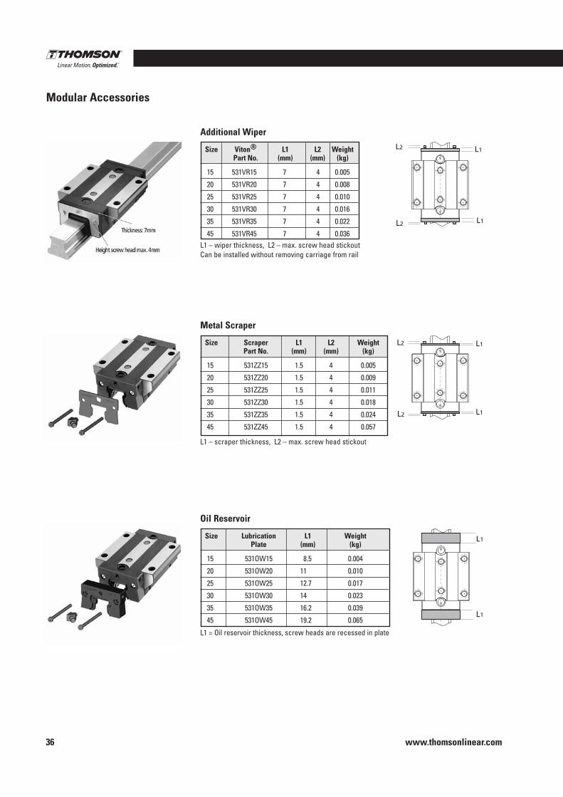
www.thomsonlinear.com36
Modular Accessories
L1
L1L1
L1
L2
L2
L1
L1
L2
L2
L1
L1L1
L1
L2
L2
L1
L1
L2
L2
L1 – wiper thickness, L2 – max . screw head stickoutCan be installed without removing carriage from rail
Additional Wiper
Size Viton® L1 L2 Weight Part No . (mm) (mm) (kg)
15 531VR15 7 4 0 .005
20 531VR20 7 4 0 .008
25 531VR25 7 4 0 .010
30 531VR30 7 4 0 .016
35 531VR35 7 4 0 .022
45 531VR45 7 4 0 .036
Metal Scraper
L1 – scraper thickness, L2 – max . screw head stickout
Size Scraper L1 L2 Weight Part No . (mm) (mm) (kg)
15 531ZZ15 1 .5 4 0 .005
20 531ZZ20 1 .5 4 0 .009
25 531ZZ25 1 .5 4 0 .011
30 531ZZ30 1 .5 4 0 .018
35 531ZZ35 1 .5 4 0 .024
45 531ZZ45 1 .5 4 0 .057
L1
L1L1
L1
L2
L2
L1
L1
L2
L2
Oil Reservoir
L1 = Oil reservoir thickness, screw heads are recessed in plate
Size Lubrication L1 Weight Plate (mm) (kg)
15 531OW15 8 .5 0 .004
20 531OW20 11 0 .010
25 531OW25 12 .7 0 .017
30 531OW30 14 0 .023
35 531OW35 16 .2 0 .039
45 531OW45 19 .2 0 .065
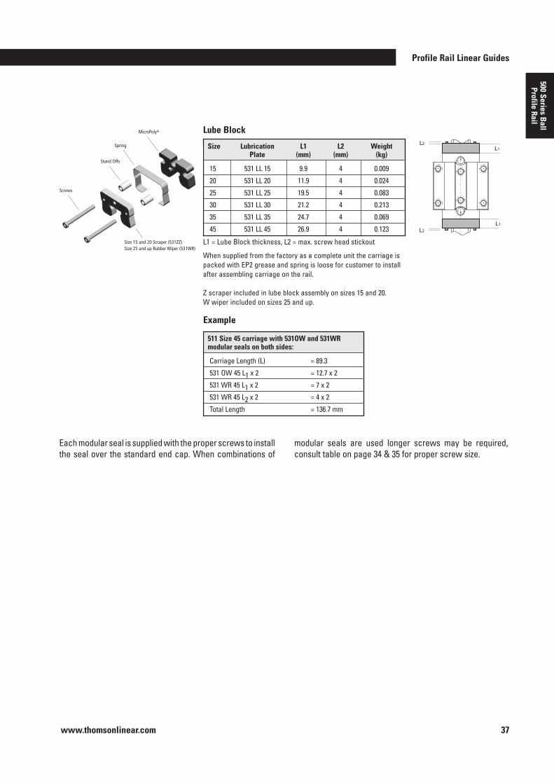
Profile Rail Linear Guides
www.thomsonlinear.com 37
500 Series Ball
Profile Rail
511 Size 45 carriage with 531OW and 531WR modular seals on both sides:
Carriage Length (L) = 89 .3
531 OW 45 L1 x 2 = 12 .7 x 2
531 WR 45 L1 x 2 = 7 x 2
531 WR 45 L2 x 2 = 4 x 2
Total Length = 136 .7 mm
Each modular seal is supplied with the proper screws to install the seal over the standard end cap . When combinations of
Example
Screws
Stand Offs
Size 15 and 20 Scraper (531ZZ) Size 25 and up Rubber Wiper (531WR)
Spring
MicroPoly® Lube Block
L1 = Lube Block thickness, L2 = max . screw head stickout
L1
L1
L2
L2
When supplied from the factory as a complete unit the carriage is packed with EP2 grease and spring is loose for customer to install after assembling carriage on the rail .
Z scraper included in lube block assembly on sizes 15 and 20 . W wiper included on sizes 25 and up .
Size Lubrication L1 L2 Weight Plate (mm) (mm) (kg)
15 531 LL 15 9 .9 4 0 .009
20 531 LL 20 11 .9 4 0 .024
25 531 LL 25 19 .5 4 0 .083
30 531 LL 30 21 .2 4 0 .213
35 531 LL 35 24 .7 4 0 .069
45 531 LL 45 26 .9 4 0 .123
modular seals are used longer screws may be required, consult table on page 34 & 35 for proper screw size .
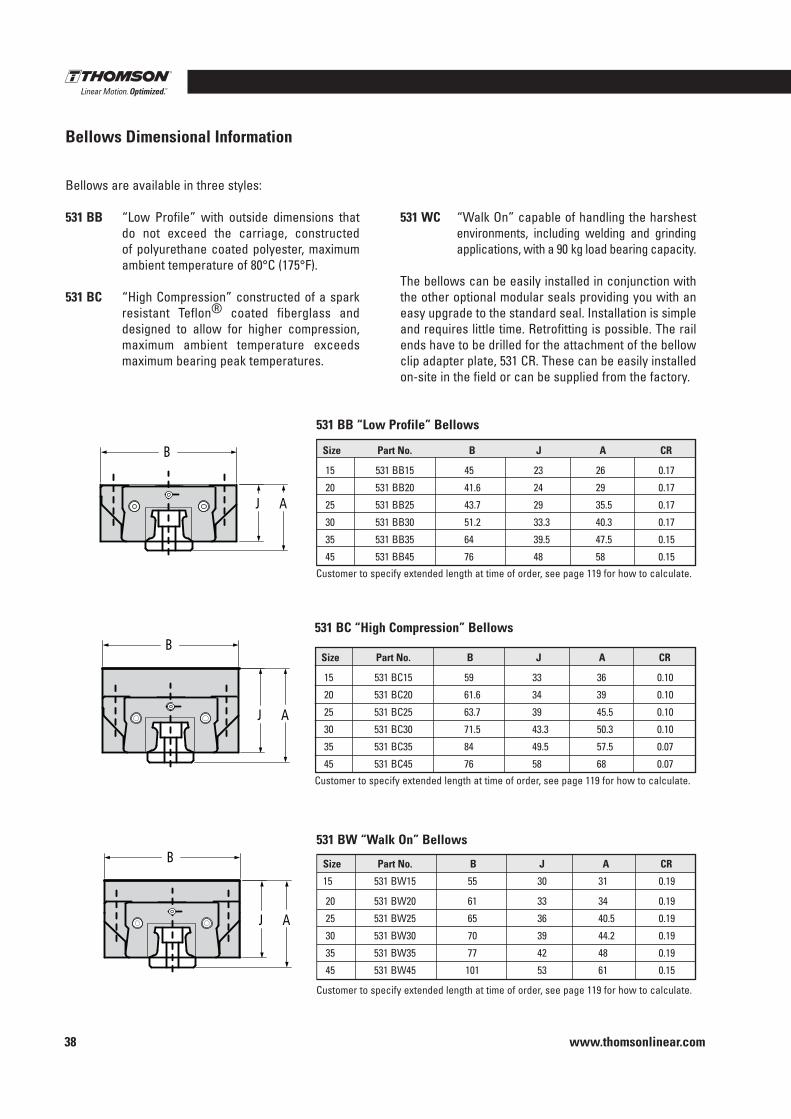
www.thomsonlinear.com38
Bellows Dimensional Information
Bellows are available in three styles:
531 BB “Low Profile” with outside dimensions that do not exceed the carriage, constructed of polyurethane coated polyester, maximum ambient temperature of 80°C (175°F) .
531 BC “High Compression” constructed of a spark resistant Teflon® coated fiberglass and designed to allow for higher compression, maximum ambient temperature exceeds maximum bearing peak temperatures .
531 WC “Walk On” capable of handling the harshest environments, including welding and grinding applications, with a 90 kg load bearing capacity .
The bellows can be easily installed in conjunction with the other optional modular seals providing you with an easy upgrade to the standard seal . Installation is simple and requires little time . Retrofitting is possible . The rail ends have to be drilled for the attachment of the bellow clip adapter plate, 531 CR . These can be easily installed on-site in the field or can be supplied from the factory .
531 BB “Low Profile” Bellows
Size Part No . B J A CR
15 531 BB15 45 23 26 0 .17
20 531 BB20 41 .6 24 29 0 .17
25 531 BB25 43 .7 29 35 .5 0 .17
30 531 BB30 51 .2 33 .3 40 .3 0 .17
35 531 BB35 64 39 .5 47 .5 0 .15
45 531 BB45 76 48 58 0 .15
Customer to specify extended length at time of order, see page 119 for how to calculate .
531 BC “High Compression” Bellows
Size Part No . B J A CR
15 531 BC15 59 33 36 0 .10
20 531 BC20 61 .6 34 39 0 .10
25 531 BC25 63 .7 39 45 .5 0 .10
30 531 BC30 71 .5 43 .3 50 .3 0 .10
35 531 BC35 84 49 .5 57 .5 0 .07
45 531 BC45 76 58 68 0 .07
Customer to specify extended length at time of order, see page 119 for how to calculate .
531 BW “Walk On” Bellows
Size Part No . B J A CR
15 531 BW15 55 30 31 0 .19
20 531 BW20 61 33 34 0 .19
25 531 BW25 65 36 40 .5 0 .19
30 531 BW30 70 39 44 .2 0 .19
35 531 BW35 77 42 48 0 .19
45 531 BW45 101 53 61 0 .15
Customer to specify extended length at time of order, see page 119 for how to calculate .
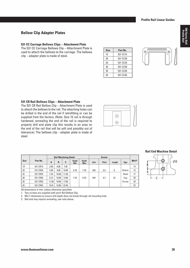
Profile Rail Linear Guides
www.thomsonlinear.com 39
500 Series Ball
Profile Rail
Bellow Clip Adapter Plates
The 531 CC Carriage Bellows Clip – Attachment Plate is used to attach the bellows to the carriage . The bellows clip – adapter plate is made of steel .
531 CC Carriage Bellows Clips – Attachment Plate
531 CR Rail Bellows Clips – Attachment Plate
Size Part No .
15 531 CC15
20 531 CC20
25 531 CC25
30 531 CC30
35 531 CC35
45 531 CC45
The 531 CR Rail Bellow Clip – Attachment Plate is used to attach the bellows to the rail . The attaching holes can be drilled in the end of the rail if retrofitting or can be supplied from the factory . (Note: Size 15 rail is through hardened, annealing the end of the rail is required to properly drill end plate clip this results in an area on the end of the rail that will be soft and possibly out of tolerance) . The bellows clip – adapter plate is made of steel .
All dimensions in mm, unless otherwise specified .1 . Two screws are supplied with each Rail Bellow Clip . 2 . Min Y dimension to ensure drill depth does not break through rail mounting hole . 3 . Rail end may require annealing, see note above .
Rail End Machine Detail
Rail Machining Detail Screw1
Size Part No . A B C
Depth Depth Size Pitch Length Type
MinY2 Min Max
153 531 CR15 3 .50 8 .00 7 .50 14
20 531 CR20 5 .00 8 .00 10 .00 5 .70 7 .70 M3 0 .5 8 Button 15
25 531 CR25 7 .24 10 .00 11 .50 Head 17
30 531 CR30 9 .12 10 .00 14 .00 7 .70 9 .70 M4 0 .7 10 Cap 20
35 531 CR35 11 .00 10 .00 17 .00 Screw 20
45 531 CR45 15 .01 10 .00 22 .50 22
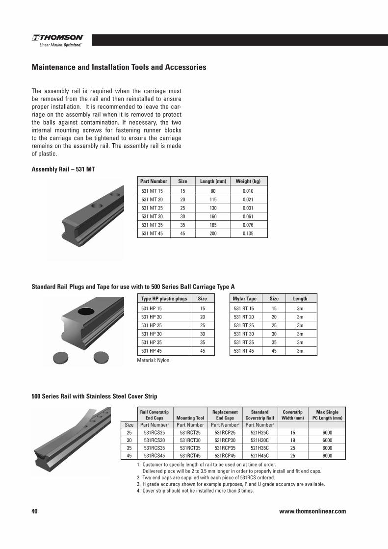
www.thomsonlinear.com40
Maintenance and Installation Tools and Accessories
The assembly rail is required when the carriage must be removed from the rail and then reinstalled to ensure proper installation . It is recommended to leave the car-riage on the assembly rail when it is removed to protect the balls against contamination . If necessary, the two internal mounting screws for fastening runner blocks to the carriage can be tightened to ensure the carriage remains on the assembly rail . The assembly rail is made of plastic .
Standard Rail Plugs and Tape for use with to 500 Series Ball Carriage Type A
Assembly Rail – 531 MT
Part Number Size Length (mm) Weight (kg)
531 MT 15 15 80 0 .010
531 MT 20 20 115 0 .021
531 MT 25 25 130 0 .031
531 MT 30 30 160 0 .061
531 MT 35 35 165 0 .076
531 MT 45 45 200 0 .135
Mylar Tape Size Length
531 RT 15 15 3m
531 RT 20 20 3m
531 RT 25 25 3m
531 RT 30 30 3m
531 RT 35 35 3m
531 RT 45 45 3m
Material: Nylon
Type HP plastic plugs Size
531 HP 15 15
531 HP 20 20
531 HP 25 25
531 HP 30 30
531 HP 35 35
531 HP 45 45
500 Series Rail with Stainless Steel Cover Strip
1 . Customer to specify length of rail to be used on at time of order . Delivered piece will be 2 to 3 .5 mm longer in order to properly install and fit end caps .
2 . Two end caps are supplied with each piece of 531RCS ordered .3 . H grade accuracy shown for example purposes, P and U grade accuracy are available .4 . Cover strip should not be installed more than 3 times .
Rail Coverstrip Replacement Standard Coverstrip Max Single End Caps Mounting Tool End Caps Coverstrip Rail Width (mm) PC Length (mm) Size Part Number1 Part Number Part Number2 Part Number3
25 531RCS25 531RCT25 531RCP25 521H25C 15 6000 30 531RCS30 531RCT30 531RCP30 521H30C 19 6000 35 531RCS35 531RCT35 531RCP35 521H35C 25 6000 45 531RCS45 531RCT45 531RCP45 521H45C 25 6000
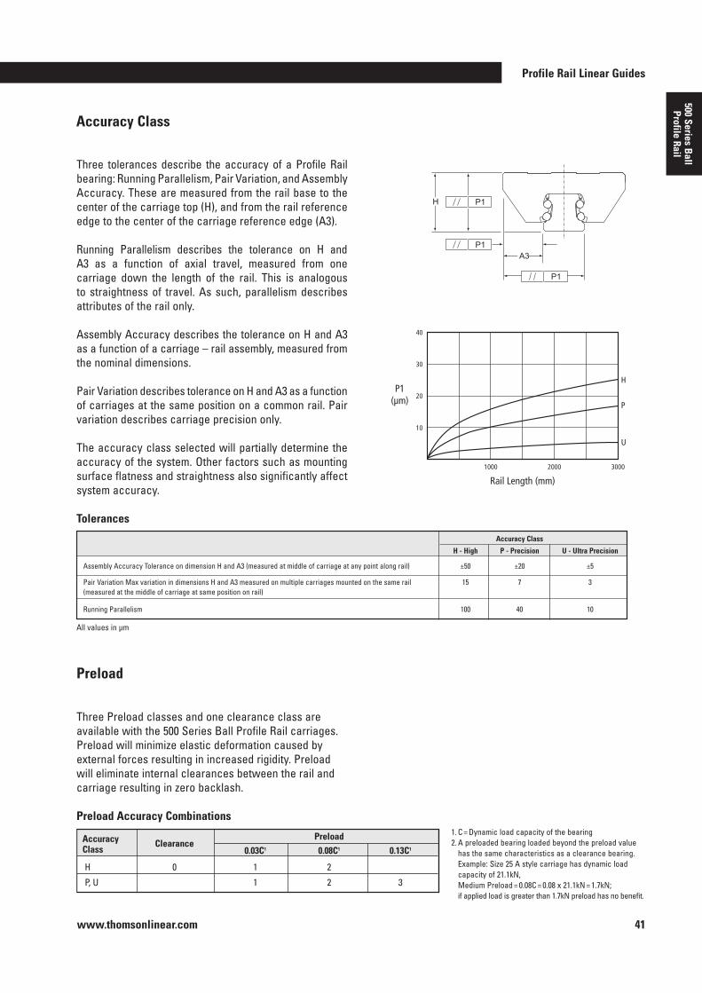
Profile Rail Linear Guides
www.thomsonlinear.com 41
500 Series Ball
Profile Rail
Accuracy Class
Three tolerances describe the accuracy of a Profile Rail bearing: Running Parallelism, Pair Variation, and Assembly Accuracy . These are measured from the rail base to the center of the carriage top (H), and from the rail reference edge to the center of the carriage reference edge (A3) .
Running Parallelism describes the tolerance on H and A3 as a function of axial travel, measured from one carriage down the length of the rail . This is analogous to straightness of travel . As such, parallelism describes attributes of the rail only .
Assembly Accuracy describes the tolerance on H and A3 as a function of a carriage – rail assembly, measured from the nominal dimensions .
Pair Variation describes tolerance on H and A3 as a function of carriages at the same position on a common rail . Pair variation describes carriage precision only .
The accuracy class selected will partially determine the accuracy of the system . Other factors such as mounting surface flatness and straightness also significantly affect system accuracy .
Rail Length (mm)
P1 (µm) P
H
U
1000
10
20
30
40
2000 3000
Tolerances
1 . C = Dynamic load capacity of the bearing2 . A preloaded bearing loaded beyond the preload value
has the same characteristics as a clearance bearing . Example: Size 25 A style carriage has dynamic load capacity of 21 .1kN, Medium Preload = 0 .08C = 0 .08 x 21 .1kN = 1 .7kN; if applied load is greater than 1 .7kN preload has no benefit .
Three Preload classes and one clearance class are available with the 500 Series Ball Profile Rail carriages . Preload will minimize elastic deformation caused by external forces resulting in increased rigidity . Preload will eliminate internal clearances between the rail and carriage resulting in zero backlash .
Accuracy Clearance Preload Class 0 .03C1 0 .08C1 0 .13C1
H 0 1 2
P, U 1 2 3
All values in µm
Accuracy Class
H - High P - Precision U - Ultra Precision Assembly Accuracy Tolerance on dimension H and A3 (measured at middle of carriage at any point along rail) ±50 ±20 ±5
Pair Variation Max variation in dimensions H and A3 measured on multiple carriages mounted on the same rail 15 7 3 (measured at the middle of carriage at same position on rail)
Running Parallelism 100 40 10
Preload
Preload Accuracy Combinations
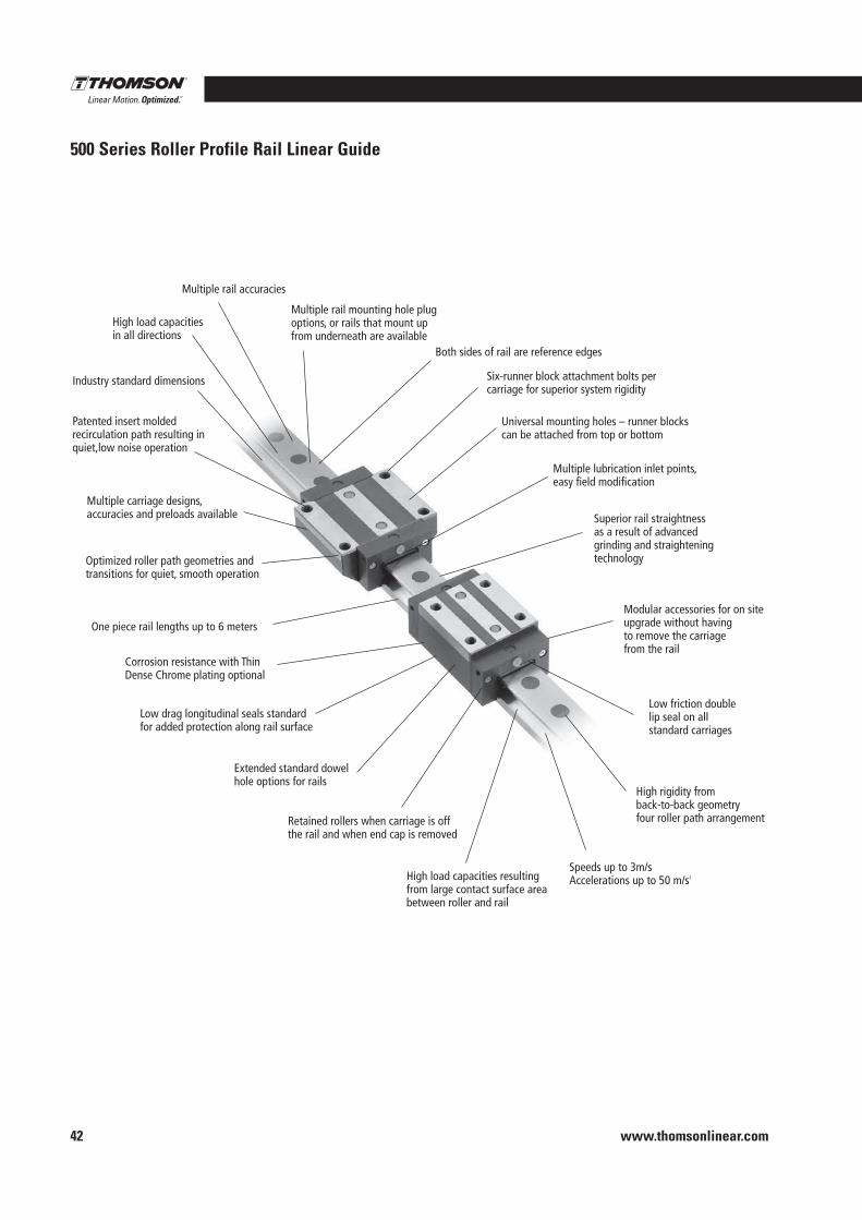
www.thomsonlinear.com42
500 Series Roller Profile Rail Linear Guide
Industry standard dimensions
High load capacities in all directions
High load capacities resulting from large contact surface area between roller and rail
Multiple rail accuracies
Multiple rail mounting hole plug options, or rails that mount up from underneath are available
Six-runner block attachment bolts per carriage for superior system rigidity
Universal mounting holes – runner blocks can be attached from top or bottom
Both sides of rail are reference edges
Multiple lubrication inlet points, easy field modification
Superior rail straightness as a result of advanced grinding and straightening technology
Modular accessories for on site upgrade without having to remove the carriage from the rail
Low friction double lip seal on all standard carriages
High rigidity from back-to-back geometry four roller path arrangement
Speeds up to 3m/s Accelerations up to 50 m/s2
Retained rollers when carriage is off the rail and when end cap is removed
Extended standard dowel hole options for rails
Low drag longitudinal seals standard for added protection along rail surface
Corrosion resistance with Thin Dense Chrome plating optional
One piece rail lengths up to 6 meters
Optimized roller path geometries and transitions for quiet, smooth operation
Multiple carriage designs, accuracies and preloads available
Patented insert molded recirculation path resulting in quiet,low noise operation
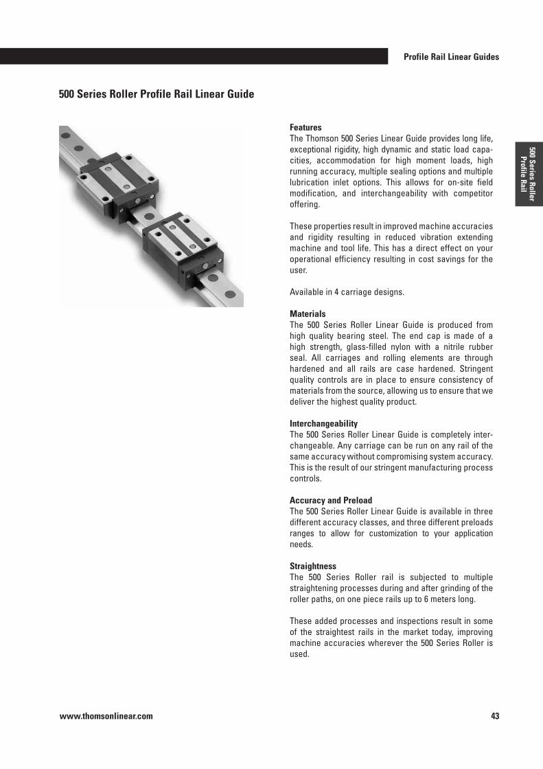
Profile Rail Linear Guides
www.thomsonlinear.com 43
500 Series Roller Profile Rail
500 Series Roller Profile Rail Linear Guide
FeaturesThe Thomson 500 Series Linear Guide provides long life, exceptional rigidity, high dynamic and static load capa-cities, accommodation for high moment loads, high running accuracy, multiple sealing options and multiple lubrication inlet options . This allows for on-site field modification, and interchangeability with competitor offering .
These properties result in improved machine accuracies and rigidity resulting in reduced vibration extending machine and tool life . This has a direct effect on your operational efficiency resulting in cost savings for the user .
Available in 4 carriage designs .
MaterialsThe 500 Series Roller Linear Guide is produced from high quality bearing steel . The end cap is made of a high strength, glass-filled nylon with a nitrile rubber seal . All carriages and rolling elements are through hardened and all rails are case hardened . Stringent quality controls are in place to ensure consistency of materials from the source, allowing us to ensure that we deliver the highest quality product .
InterchangeabilityThe 500 Series Roller Linear Guide is completely inter-changeable . Any carriage can be run on any rail of the same accuracy without compromising system accuracy . This is the result of our stringent manufacturing process controls .
Accuracy and PreloadThe 500 Series Roller Linear Guide is available in three different accuracy classes, and three different preloads ranges to allow for customization to your application needs .
StraightnessThe 500 Series Roller rail is subjected to multiple straightening processes during and after grinding of the roller paths, on one piece rails up to 6 meters long .
These added processes and inspections result in some of the straightest rails in the market today, improving machine accuracies wherever the 500 Series Roller is used .
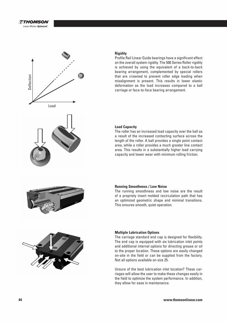
www.thomsonlinear.com44
RigidityProfile Rail Linear Guide bearings have a significant effect on the overall system rigidity . The 500 Series Roller rigidity is achieved by using the equivalent of a back-to-back bearing arrangement, complemented by special rollers that are crowned to prevent roller edge loading when misalignment is present . This results in lower elastic deformation as the load increases compared to a ball carriage or face-to-face bearing arrangement .
Load CapacityThe roller has an increased load capacity over the ball as a result of the increased contacting surface across the length of the roller . A ball provides a single point contact area, while a roller provides a much greater line contact area . This results in a substantially higher load carrying capacity and lower wear with minimum rolling friction .
Running Smoothness / Low NoiseThe running smoothness and low noise are the result of a propriety insert molded recirculation path that has an optimized geometric shape and minimal transitions . This ensures smooth, quiet operation .
Multiple Lubrication OptionsThe carriage standard end cap is designed for flexibility . The end cap is equipped with six lubrication inlet points and additional internal options for directing grease or oil to the proper location . These options are easily changed on-site in the field or can be supplied from the factory . Not all options available on size 25 .
Unsure of the best lubrication inlet location? These car-riages will allow the user to make these changes easily in the field to optimize the system performance . In addition, they allow for ease in maintenance .
Defle
ctio
n
Load
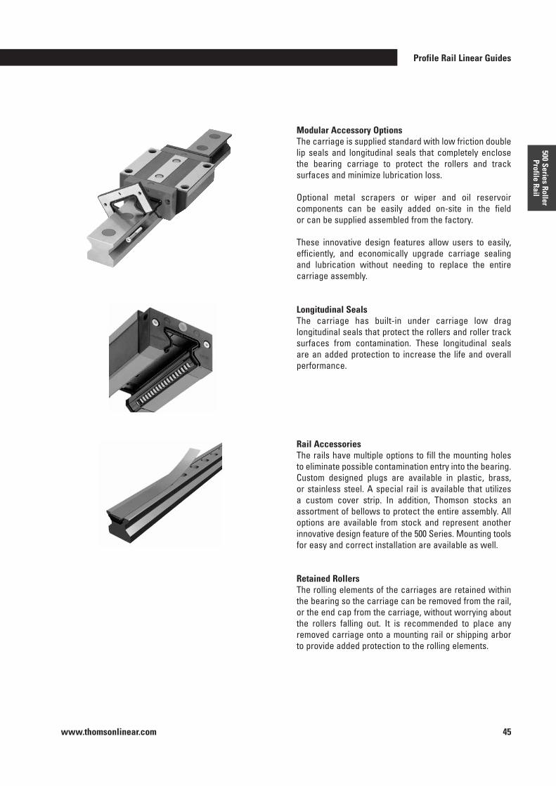
Profile Rail Linear Guides
www.thomsonlinear.com 45
500 Series Roller Profile Rail
Modular Accessory OptionsThe carriage is supplied standard with low friction double lip seals and longitudinal seals that completely enclose the bearing carriage to protect the rollers and track surfaces and minimize lubrication loss .
Optional metal scrapers or wiper and oil reservoir components can be easily added on-site in the field or can be supplied assembled from the factory .
These innovative design features allow users to easily, efficiently, and economically upgrade carriage sealing and lubrication without needing to replace the entire carriage assembly .
Longitudinal SealsThe carriage has built-in under carriage low drag longitudinal seals that protect the rollers and roller track surfaces from contamination . These longitudinal seals are an added protection to increase the life and overall performance .
Rail AccessoriesThe rails have multiple options to fill the mounting holes to eliminate possible contamination entry into the bearing . Custom designed plugs are available in plastic, brass, or stainless steel . A special rail is available that utilizes a custom cover strip . In addition, Thomson stocks an assortment of bellows to protect the entire assembly . All options are available from stock and represent another innovative design feature of the 500 Series . Mounting tools for easy and correct installation are available as well .
Retained RollersThe rolling elements of the carriages are retained within the bearing so the carriage can be removed from the rail, or the end cap from the carriage, without worrying about the rollers falling out . It is recommended to place any removed carriage onto a mounting rail or shipping arbor to provide added protection to the rolling elements .
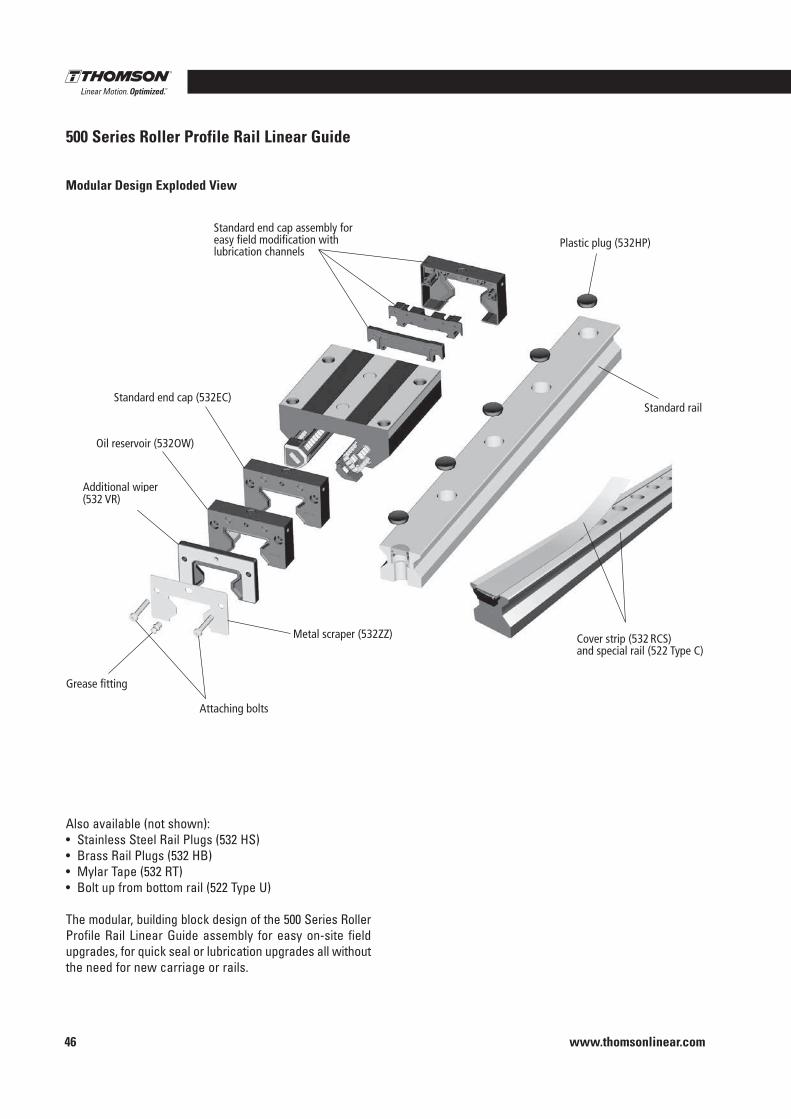
www.thomsonlinear.com46
500 Series Roller Profile Rail Linear Guide
Standard end cap assembly for easy field modification with lubrication channels
Plastic plug (532HP)
Standard rail
Cover strip (532 RCS) and special rail (522 Type C)
Standard end cap (532EC)
Oil reservoir (532OW)
Additional wiper (532WR or VR)
Metal scraper (532ZZ)
Attaching bolts
Grease fitting
Also available (not shown):• Stainless Steel Rail Plugs (532 HS)• Brass Rail Plugs (532 HB)• Mylar Tape (532 RT)• Bolt up from bottom rail (522 Type U)
The modular, building block design of the 500 Series Roller Profile Rail Linear Guide assembly for easy on-site field upgrades, for quick seal or lubrication upgrades all without the need for new carriage or rails .
Modular Design Exploded View
(532 VR)
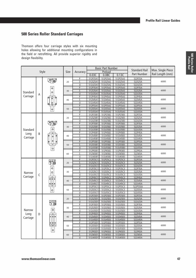
Profile Rail Linear Guides
www.thomsonlinear.com 47
500 Series Roller Profile Rail
Thomson offers four carriage styles with six mounting holes allowing for additional mounting configurations in the field or retrofitting . All provide superior rigidity and design flexibility .
500 Series Roller Standard Carriages
6000 6000 6000 6000 6000 6000 6000 6000 6000 6000 6000 6000 6000 6000 6000 6000 6000 6000
512P25A1512S25A1512U25A1512P35A1512S35A1512U35A1512P45A1512S45A1512U45A1512P55A1512S55A1512U55A1512P25B1512S25B1512U25B1512P35B1512S35B1512U35B1512P45B1512S45B1512U45B1512P55B1512S55B1512U55B1512P65B1512S65B1512U65B1512P25C1512S25C1512U25C1512P35C1512S35C1512U35C1512P45C1512S45C1512U45C1512P55C1512S55C1512U55C1512P25D1512S25D1512U25D1512P35D1512S35D1512U35D1512P45D1512S45D1512U45D1512P55D1512S55D1512U55D1512P65D1512S65D1512U65D1
P S U P S U P S U P S U P S U P S U P S U P S U P S U P S U P S U P S U P S U P S U P S U P S U P S U P S U
512P25A2512S25A2512U25A2512P35A2512S35A2512U35A2512P45A2512S45A2512U45A2512P55A2512S55A2512U55A2512P25B2512S25B2512U25B2512P35B2512S35B2512U35B2512P45B2512S45B2512U45B2512P55B2512S55B2512U55B2512P65B2512S65B2512U65B2512P25C2512S25C2512U25C2512P35C2512S35C2512U35C2512P45C2512S45C2512U45C2512P55C2512S55C2512U55C2512P25D2512S25D2512U25D2512P35D2512S35D2512U35D2512P45D2512S45D2512U45D2512P55D2512S55D2512U55D2512P65D2512S65D2512U65D2
512P25A3512S25A3512U25A3512P35A3512S35A3512U35A3512P45A3512S45A3512U45A3512P55A3512S55A3512U55A3512P25B3512S25B3512U25B3512P35B3512S35B3512U35B3512P45B3512S45B3512U45B3512P55B3512S55B3512U55B3512P65B3512S65B3512U65B3512P25C3512S25C3512U25C3512P35C3512S35C3512U35C3512P45C3512S45C3512U45C3512P55C3512S55C3512U55C3512P25D3512S25D3512U25D3512S35D3512S35D3512U35D3512P45D3512S45D3512U45D3512P55D3512S55D3512U55D3512P65D3512S65D3512U65D3
522P25A522S25A522U25A522P35A522S35A522U35A522P45A522S45A522U45A522P55A522S55A522U55A522P25A522S25A522U25A522P35A522S35A522U35A522P45A522S45A522U45A522P55A522S55A522U55A522P65A522S65A522U65A522P25A522S25A522U25A522P35A522S35A522U35A522P45A522S45A522U45A522P550A522S55A522U55A522P25A522S25A522U25A522P35A522S35A522U35A522P45A522S45A522U45A522P55A522S55A522U55A522P65A522S65A522U65A
SizeStyle
StandardCarriage A
B
CNarrowCarriage
DNarrow
LongCarriage
Standard Long
Carriage
Accuracy0.03C 0.08C
PreloadBasic Part Number
0.13C
Standard RailPart Number
Max. Single PieceRail Length (mm)
25 35 45 55 25 35 45 55 65 25 35 45 55 25 35 45 55 65
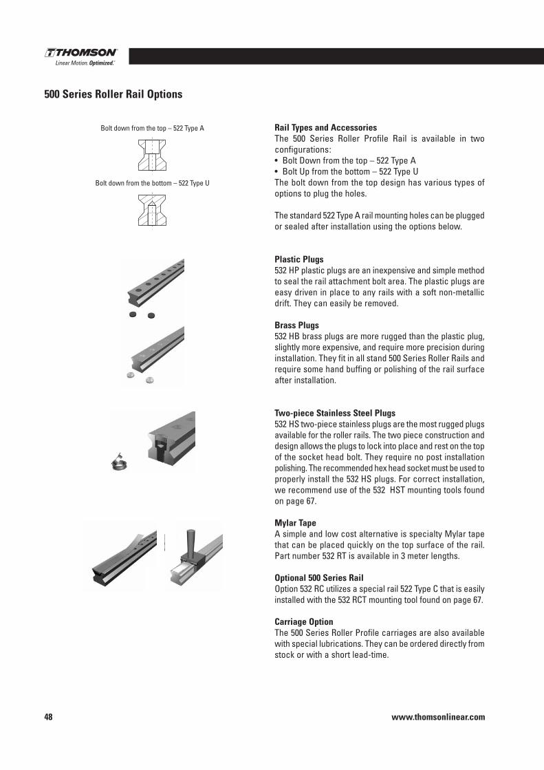
www.thomsonlinear.com48
500 Series Roller Rail Options
Rail Types and AccessoriesThe 500 Series Roller Profile Rail is available in two configurations :• Bolt Down from the top – 522 Type A• Bolt Up from the bottom – 522 Type UThe bolt down from the top design has various types of options to plug the holes .
The standard 522 Type A rail mounting holes can be plugged or sealed after installation using the options below .
Plastic Plugs532 HP plastic plugs are an inexpensive and simple method to seal the rail attachment bolt area . The plastic plugs are easy driven in place to any rails with a soft non-metallic drift . They can easily be removed .
Brass Plugs532 HB brass plugs are more rugged than the plastic plug, slightly more expensive, and require more precision during installation . They fit in all stand 500 Series Roller Rails and require some hand buffing or polishing of the rail surface after installation .
Two-piece Stainless Steel Plugs532 HS two-piece stainless plugs are the most rugged plugs available for the roller rails . The two piece construction and design allows the plugs to lock into place and rest on the top of the socket head bolt . They require no post installation polishing . The recommended hex head socket must be used to properly install the 532 HS plugs . For correct installation, we recommend use of the 532 HST mounting tools found on page 67 .
Mylar TapeA simple and low cost alternative is specialty Mylar tape that can be placed quickly on the top surface of the rail . Part number 532 RT is available in 3 meter lengths .
Optional 500 Series RailOption 532 RC utilizes a special rail 522 Type C that is easily installed with the 532 RCT mounting tool found on page 67 .
Carriage OptionThe 500 Series Roller Profile carriages are also available with special lubrications . They can be ordered directly from stock or with a short lead-time .
Bolt down from the bottom – 522 Type U
Bolt down from the top – 522 Type A
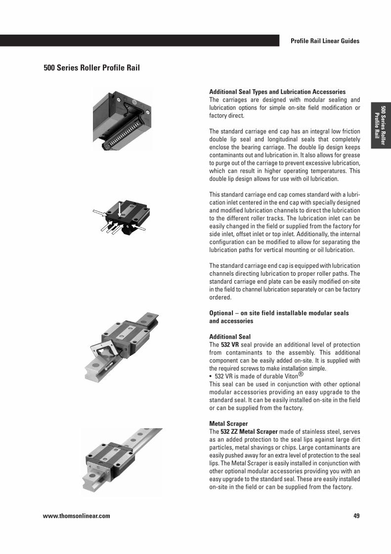
Profile Rail Linear Guides
www.thomsonlinear.com 49
500 Series Roller Profile Rail
Additional Seal Types and Lubrication AccessoriesThe carriages are designed with modular sealing and lubrication options for simple on-site field modification or factory direct .
The standard carriage end cap has an integral low friction double lip seal and longitudinal seals that completely enclose the bearing carriage . The double lip design keeps contaminants out and lubrication in . It also allows for grease to purge out of the carriage to prevent excessive lubrication, which can result in higher operating temperatures . This double lip design allows for use with oil lubrication .
This standard carriage end cap comes standard with a lubri-cation inlet centered in the end cap with specially designed and modified lubrication channels to direct the lubrication to the different roller tracks . The lubrication inlet can be easily changed in the field or supplied from the factory for side inlet, offset inlet or top inlet . Additionally, the internal configuration can be modified to allow for separating the lubrication paths for vertical mounting or oil lubrication .
The standard carriage end cap is equipped with lubrication channels directing lubrication to proper roller paths . The standard carriage end plate can be easily modified on-site in the field to channel lubrication separately or can be factory ordered .
Optional – on site field installable modular seals and accessories
Additional SealThe 532 VR seal provide an additional level of protection from contaminants to the assembly . This additional component can be easily added on-site . It is supplied with the required screws to make installation simple .• 532 VR is made of durable Viton®This seal can be used in conjunction with other optional modular accessories providing an easy upgrade to the standard seal . It can be easily installed on-site in the field or can be supplied from the factory .
Metal ScraperThe 532 ZZ Metal Scraper made of stainless steel, serves as an added protection to the seal lips against large dirt particles, metal shavings or chips . Large contaminants are easily pushed away for an extra level of protection to the seal lips . The Metal Scraper is easily installed in conjunction with other optional modular accessories providing you with an easy upgrade to the standard seal . These are easily installed on-site in the field or can be supplied from the factory .
500 Series Roller Profile Rail
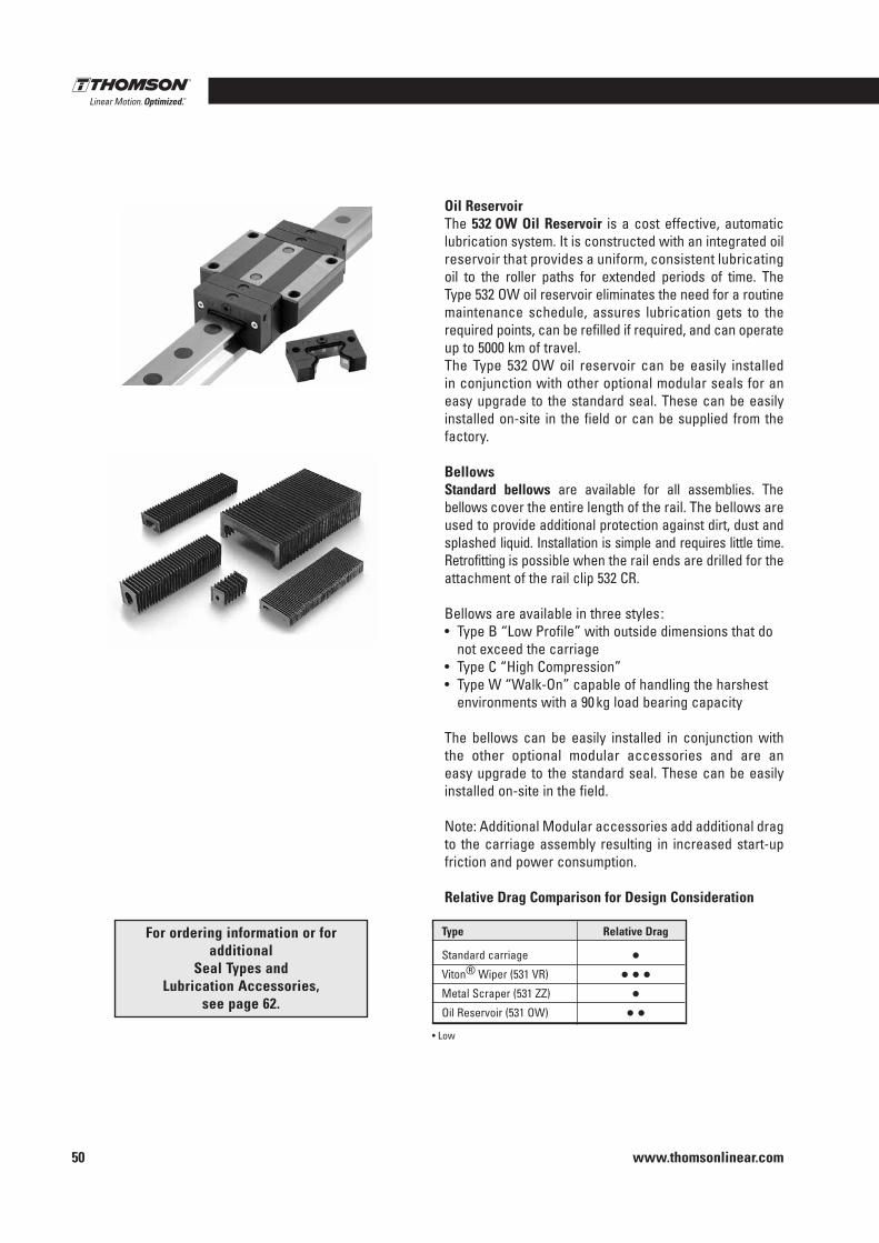
www.thomsonlinear.com50
Oil ReservoirThe 532 OW Oil Reservoir is a cost effective, automatic lubrication system . It is constructed with an integrated oil reservoir that provides a uniform, consistent lubricating oil to the roller paths for extended periods of time . The Type 532 OW oil reservoir eliminates the need for a routine maintenance schedule, assures lubrication gets to the required points, can be refilled if required, and can operate up to 5000 km of travel .The Type 532 OW oil reservoir can be easily installed in conjunction with other optional modular seals for an easy upgrade to the standard seal . These can be easily installed on-site in the field or can be supplied from the factory .
BellowsStandard bellows are available for all assemblies . The bellows cover the entire length of the rail . The bellows are used to provide additional protection against dirt, dust and splashed liquid . Installation is simple and requires little time . Retrofitting is possible when the rail ends are drilled for the attachment of the rail clip 532 CR .
Bellows are available in three styles :• Type B “Low Profile” with outside dimensions that do
not exceed the carriage• Type C “High Compression”• Type W “Walk-On” capable of handling the harshest
environments with a 90 kg load bearing capacity
The bellows can be easily installed in conjunction with the other optional modular accessories and are an easy up grade to the standard seal . These can be easily installed on-site in the field .
Note: Additional Modular accessories add additional drag to the carriage assembly resulting in increased start-up friction and power consumption .
Relative Drag Comparison for Design Consideration
Type Relative Drag
Standard carriage •Viton® Wiper (531 VR) • • •Metal Scraper (531 ZZ) •Oil Reservoir (531 OW) • •
• Low
For ordering information or for additional
Seal Types and Lubrication Accessories,
see page 62 .
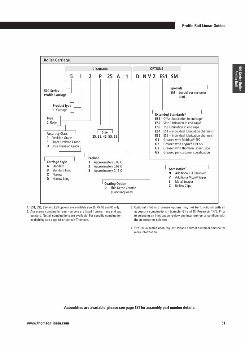
Profile Rail Linear Guides
www.thomsonlinear.com 51
500 Series Roller Profile Rail
StandardSTANDARD OPTIONS
Roller Carriage
500 Series Profile Carriage
Product Type1 Carriage
5 1 2 P 25 A 1 ES1 SMN V ZD
SpecialsSM Special per customer print
Extended Standards3
ES1 Offset lubrication in end caps1 ES2 Side lubrication in end caps1
ES3 Top lubrication in end capsES4 ES1 + individual lubrication channels1
ES5 ES2 + individual lubrication channels1 G1 Greased with Mobilux® EP2 G2 Greased with Krytox® GPL227G3 Greased with Thomson Linear LubeGS Greased per customer specification
AccessoriesD Duralloy® (P class only)L Long Life Lube Lock N Additional Oil Reservoir Z Metal Scraper W Additional Rubber Wiper V Additional Viton® Wiper C Bellow Clips
Accuracy Class P Precision GradeS Super Precision GradeU Ultra Precision Grade
Size25, 35, 45, 55, 65
Carriage Style A StandardB Standard LongC NarrowD Narrow Long
Preload 1 Approximately 0.03 C2 Approximately 0.08 C3 Approximately 0.13 C
Type2 Roller
Accessories2 N Additional Oil Reservoir V Additional Viton® Wiper Z Metal ScraperC Bellow Clips
Coating Option D Thin Dense Chrome (P accuracy only)
1 . ES1, ES2, ES4 and ES5 options are available size 35, 45, 55 and 65 only .2 . Accessory combination part numbers are listed from carriage end cap
outward . Not all combinations are available . For specific combination availability see page 61 or consult Thomson .
3 . Optional inlet and grease options may not be functional with all accessory combinations . (Example: G1 and Oil Reservoir “N”) . Prior to selecting an inlet option review any interference or conflicts with the accessories selected .
4 . Size 100 available upon request . Please contact customer service for more information .
Assemblies are available, please see page 121 for assembly part number details .
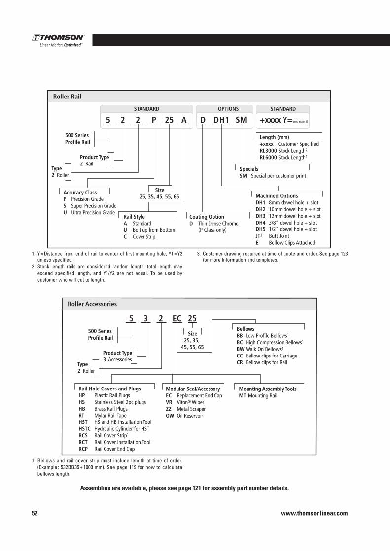
www.thomsonlinear.com52
Standard STANDARD STANDARD OPTIONS
Roller Rail
500 Series Profile Rail
Product Type 2 Rail
5 2 2 P 25 A D SMDH1
Length (mm) +xxxx Customer Specified RL3000 Stock Length2
RL6000 Stock Length2
Specials SM Special per customer print
Machined Options DH1 8mm dowel hole + slot DH2 10mm dowel hole + slot DH3 12mm dowel hole + slot DH4 3/8” dowel hole + slot DH5 1/2” dowel hole + slot JT3 Butt Joint E Bellow Clips Attached
Accuracy Class P Precision Grade S Super Precision Grade U Ultra Precision Grade
Size 25, 35, 45, 55, 65
Rail Style A Standard U Bolt up from Bottom C Cover Strip
Coating Option D Thin Dense Chrome (P Class only)
Type 2 Roller
+xxxx Y= (see note 1)
1 . Y = Distance from end of rail to center of first mounting hole, Y1 = Y2 unless specified .
2 . Stock length rails are considered random length, total length may exceed specified length, and Y1/Y2 are not equal . To be used by customer who will cut to length .
3 . Customer drawing required at time of quote and order . See page 123 for more information and templates .
1 . Bellows and rail cover strip must include length at time of order . (Example : 532BB35 + 1000 mm) . See page 119 for how to calculate bellows length .
Roller Accessories
500 Series Profile Rail
Product Type 3 Accessories
5 3 2 EC 25
Size 25, 35,
45, 55, 65
Rail Hole Covers and PlugsHP Plastic Rail PlugsHS Stainless Steel 2pc plugsHB Brass Rail PlugsRT Mylar Rail TapeHST HS and HB Installation ToolHSTC Hydraulic Cylinder for HSTRCS Rail Cover Strip1
RCT Rail Cover Installation ToolRCP Rail Cover End Cap
Modular Seal/Accessory EC Replacement End CapVR Viton® WiperZZ Metal ScraperOW Oil Reservoir
Type 2 Roller
Mounting Assembly Tools MT Mounting Rail
Bellows BB Low Profile Bellows1
BC High Compression Bellows1
BW Walk On Bellows1
CC Bellow clips for Carriage CR Bellow clips for Rail
Assemblies are available, please see page 121 for assembly part number details .
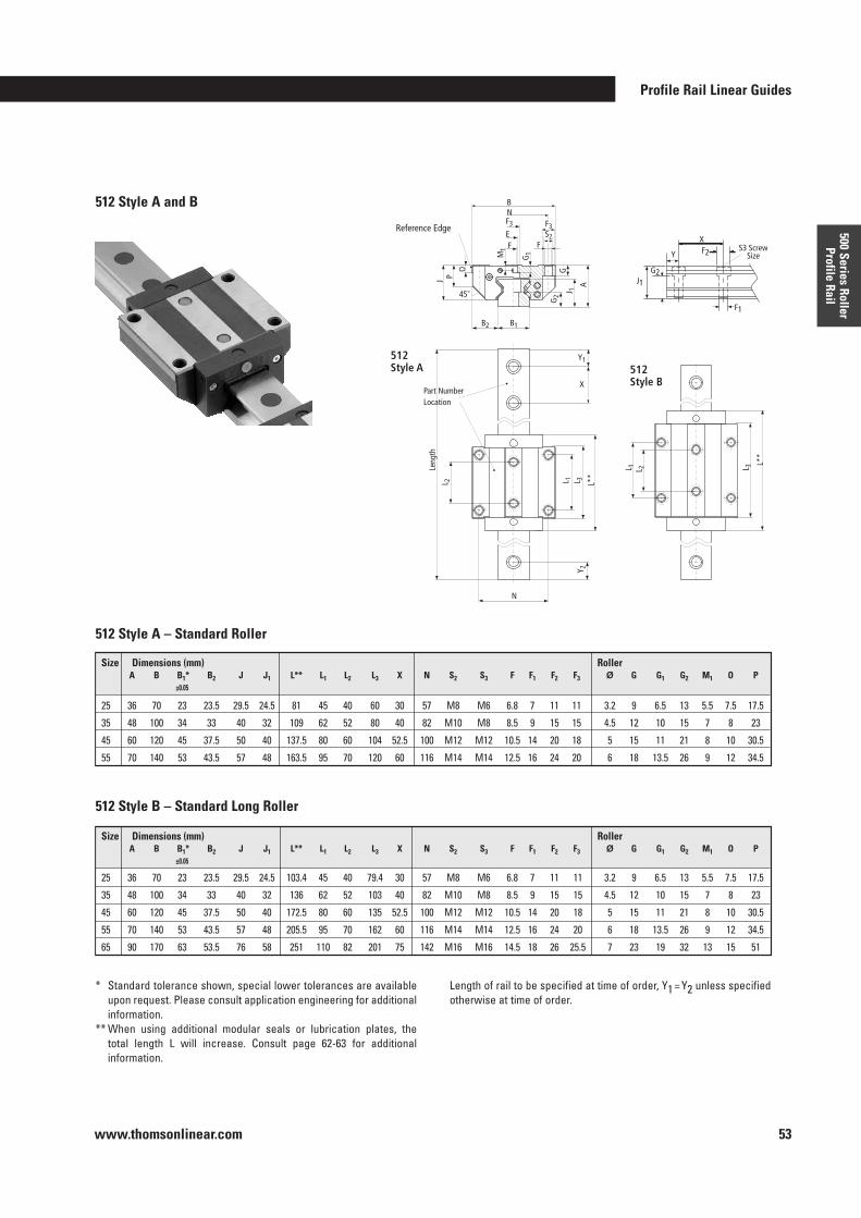
Profile Rail Linear Guides
www.thomsonlinear.com 53
500 Series Roller Profile Rail
512 Style A and B
M1
E
F3
G1
FS2
F3
NB
J P
O
45°
B2 B1
G2
J 1A
G
L 2
Y 2
L 1 L 3 L**
X
Y1
L 1 L 2 L 3L*
*
F
512Style A 512
Style BPart Number Location
Reference Edge
N
J1
F1
Y
XS3 Screw
SizeF2
G2
Leng
th
512 Style A – Standard Roller
512 Style B – Standard Long Roller
* Standard tolerance shown, special lower tolerances are available upon request . Please consult application engineering for additional information .
** When using additional modular seals or lubrication plates, the total length L will increase . Consult page 62-63 for additional information .
Length of rail to be specified at time of order, Y1 = Y2 unless specified otherwise at time of order .
Size Dimensions (mm) Roller A B B1* B2 J J1 L** L1 L2 L3 X N S2 S3 F F1 F2 F3 Ø G G1 G2 M1 O P ±0 .05
25 36 70 23 23 .5 29 .5 24 .5 81 45 40 60 30 57 M8 M6 6 .8 7 11 11 3 .2 9 6 .5 13 5 .5 7 .5 17 .5
35 48 100 34 33 40 32 109 62 52 80 40 82 M10 M8 8 .5 9 15 15 4 .5 12 10 15 7 8 23
45 60 120 45 37 .5 50 40 137 .5 80 60 104 52 .5 100 M12 M12 10 .5 14 20 18 5 15 11 21 8 10 30 .5
55 70 140 53 43 .5 57 48 163 .5 95 70 120 60 116 M14 M14 12 .5 16 24 20 6 18 13 .5 26 9 12 34 .5
Size Dimensions (mm) Roller A B B1* B2 J J1 L** L1 L2 L3 X N S2 S3 F F1 F2 F3 Ø G G1 G2 M1 O P ±0 .05
25 36 70 23 23 .5 29 .5 24 .5 103 .4 45 40 79 .4 30 57 M8 M6 6 .8 7 11 11 3 .2 9 6 .5 13 5 .5 7 .5 17 .5
35 48 100 34 33 40 32 136 62 52 103 40 82 M10 M8 8 .5 9 15 15 4 .5 12 10 15 7 8 23
45 60 120 45 37 .5 50 40 172 .5 80 60 135 52 .5 100 M12 M12 10 .5 14 20 18 5 15 11 21 8 10 30 .5
55 70 140 53 43 .5 57 48 205 .5 95 70 162 60 116 M14 M14 12 .5 16 24 20 6 18 13 .5 26 9 12 34 .5
65 90 170 63 53 .5 76 58 251 110 82 201 75 142 M16 M16 14 .5 18 26 25 .5 7 23 19 32 13 15 51
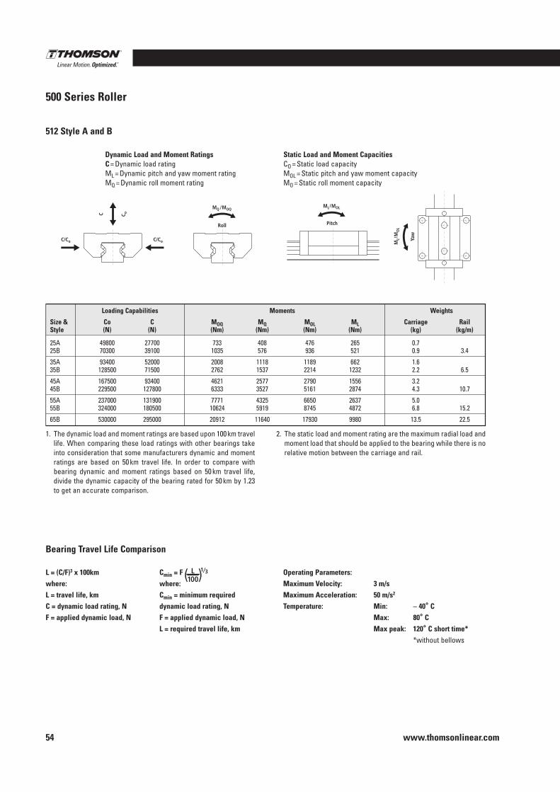
www.thomsonlinear.com54
500 Series Roller
512 Style A and B
Dynamic Load and Moment RatingsC = Dynamic load ratingML = Dynamic pitch and yaw moment ratingMQ = Dynamic roll moment rating
Static Load and Moment CapacitiesCO = Static load capacityMOL = Static pitch and yaw moment capacityMO = Static roll moment capacity
C/Co C/Co
C C o
MQ /MOQ
Pitch Roll
ML/MOL
Yaw
ML/
MO
L
1 . The dynamic load and moment ratings are based upon 100 km travel life . When comparing these load ratings with other bearings take into consideration that some manufacturers dynamic and moment ratings are based on 50 km travel life . In order to compare with bearing dynamic and moment ratings based on 50 km travel life, divide the dynamic capacity of the bearing rated for 50 km by 1 .23 to get an accurate comparison .
2 . The static load and moment rating are the maximum radial load and moment load that should be applied to the bearing while there is no relative motion between the carriage and rail .
Loading Capabilities Moments Weights
Size & Co C MOQ MQ MOL ML Carriage Rail Style (N) (N) (Nm) (Nm) (Nm) (Nm) (kg) (kg/m)
25A 49800 27700 733 408 476 265 0 .7 25B 70300 39100 1035 576 936 521 0 .9 3 .4
35A 93400 52000 2008 1118 1189 662 1 .6 35B 128500 71500 2762 1537 2214 1232 2 .2 6 .5
45A 167500 93400 4621 2577 2790 1556 3 .2 45B 229500 127800 6333 3527 5161 2874 4 .3 10 .7
55A 237000 131900 7771 4325 6650 2637 5 .0 55B 324000 180500 10624 5919 8745 4872 6 .8 15 .2
65B 530000 295000 20912 11640 17930 9980 13 .5 22 .5
L = (C/F)3 x 100kmwhere:L = travel life, kmC = dynamic load rating, NF = applied dynamic load, N
Cmin = F ( ) L 100
1⁄3
where:Cmin = minimum required dynamic load rating, NF = applied dynamic load, NL = required travel life, km
Operating Parameters:Maximum Velocity: 3 m/s Maximum Acceleration: 50 m/s2
Temperature: Min: – 40° C Max: 80° C Max peak: 120° C short time* *without bellows
Bearing Travel Life Comparison
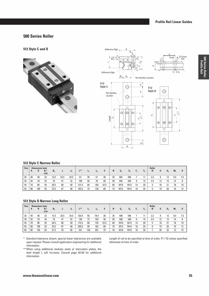
Profile Rail Linear Guides
www.thomsonlinear.com 55
500 Series Roller Profile Rail
500 Series Roller
512 Style C Narrow Roller
* Standard tolerance shown, special lower tolerances are available upon request . Please consult application engineering for additional information .
** When using additional modular seals or lubrication plates, the total length L will increase . Consult page 62-63 for additional information .
Length of rail to be specified at time of order, Y1 = Y2 unless specified otherwise at time of order .
512 Style D Narrow Long Roller
M1 O
J
B N
G
A J 1
G 2
B1 B2
Leng
th
L 3
Y 2
L 1
L** L 3
L 1 L*
*
Reference Edge
Reference Edge
512 Style C 512
Style D
Part Number Location
Part Number Location
J1
F1
Y
X S3 Screw
Size F2
G2
X
Y1
N
S2
512 Style C and D
Size Dimensions (mm) Roller A B B1* B2 J J1 L** L1 L3 X N S2 S3 F1 F2 Ø G G2 M1 O +0 .05
25 40 48 23 12 .5 33 .5 24 .5 81 35 57 30 35 M6 M6 7 11 3 .2 9 13 9 .5 7 .535 55 70 34 18 47 32 109 50 76 40 50 M8 M8 9 15 4 .5 12 15 14 845 70 86 45 20 .5 60 40 137 .5 60 100 52 .5 60 M10 M12 14 20 5 18 21 18 1055 80 100 53 23 .5 67 48 163 .5 75 120 60 75 M12 M14 16 24 6 19 26 19 12
Size Dimensions (mm) Roller A B B1* B2 J J1 L** L1 L3 X N S2 S3 F1 F2 Ø G G2 M1 O +0 .05
25 40 48 23 12 .5 33 .5 24 .5 103 .4 50 79 .4 30 35 M6 M6 7 11 3 .2 9 13 9 .5 7 .535 55 70 34 18 47 32 136 72 103 40 50 M8 M8 9 15 4 .5 12 15 14 845 70 86 45 20 .5 60 40 172 .5 80 135 52 .5 60 M10 M12 14 20 5 18 21 18 1055 80 100 53 23 .5 67 48 205 .5 95 162 60 75 M12 M14 16 24 6 19 26 19 1265 90 126 63 31 .5 76 58 251 120 201 75 76 M16 M16 18 26 7 20 32 13 15
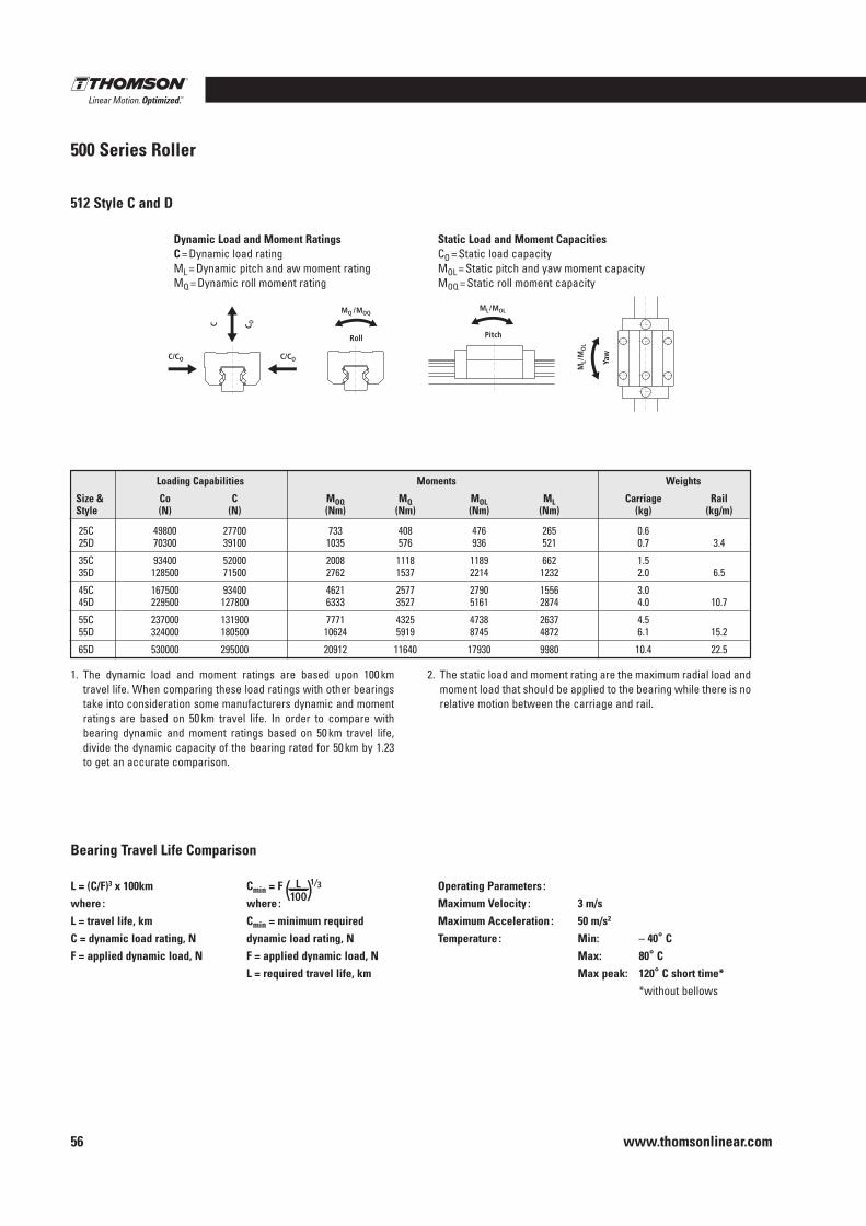
www.thomsonlinear.com56
500 Series Roller
L = (C/F)3 x 100kmwhere :L = travel life, kmC = dynamic load rating, NF = applied dynamic load, N
Cmin = F ( ) L 100
1⁄3
where :Cmin = minimum required dynamic load rating, NF = applied dynamic load, NL = required travel life, km
Operating Parameters :Maximum Velocity : 3 m/s Maximum Acceleration : 50 m/s2
Temperature : Min: – 40° C Max: 80° C Max peak: 120° C short time* *without bellows
Bearing Travel Life Comparison
512 Style C and D
Dynamic Load and Moment RatingsC = Dynamic load ratingML = Dynamic pitch and aw moment ratingMQ = Dynamic roll moment rating
Static Load and Moment CapacitiesCO = Static load capacityMOL = Static pitch and yaw moment capacityMOQ = Static roll moment capacity
1 . The dynamic load and moment ratings are based upon 100 km travel life . When comparing these load ratings with other bearings take into consideration some manufacturers dynamic and moment ratings are based on 50 km travel life . In order to compare with bearing dynamic and moment ratings based on 50 km travel life, divide the dynamic capacity of the bearing rated for 50 km by 1 .23 to get an accurate comparison .
2 . The static load and moment rating are the maximum radial load and moment load that should be applied to the bearing while there is no relative motion between the carriage and rail .
C/CO C/CO
C C O
MQ /MOQ
Pitch Roll
ML/MOL
Yaw
ML/
MO
L
Loading Capabilities Moments Weights
Size & Co C MOQ MQ MOL ML Carriage Rail Style (N) (N) (Nm) (Nm) (Nm) (Nm) (kg) (kg/m)
25C 49800 27700 733 408 476 265 0 .6 25D 70300 39100 1035 576 936 521 0 .7 3 .4
35C 93400 52000 2008 1118 1189 662 1 .5 35D 128500 71500 2762 1537 2214 1232 2 .0 6 .5
45C 167500 93400 4621 2577 2790 1556 3 .0 45D 229500 127800 6333 3527 5161 2874 4 .0 10 .7
55C 237000 131900 7771 4325 4738 2637 4 .5 55D 324000 180500 10624 5919 8745 4872 6 .1 15 .2
65D 530000 295000 20912 11640 17930 9980 10 .4 22 .5
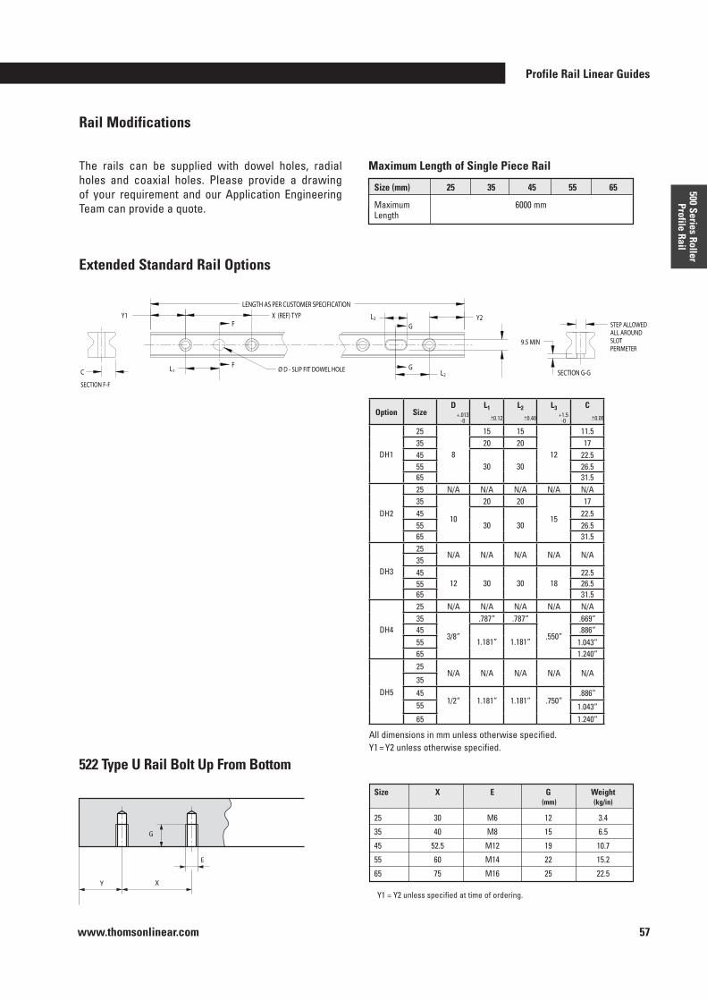
Profile Rail Linear Guides
www.thomsonlinear.com 57
500 Series Roller Profile Rail
The rails can be supplied with dowel holes, radial holes and coaxial holes . Please provide a drawing of your requirement and our Application Engineering Team can provide a quote .
Rail Modifications
Pat Rocco 6/18/04
Al Ng 6/18/04
B 12008 ADD 522X25XXDH2 TO THE TABLEDMI
8/11/05
DWG NO.DRAWN BY: DATE
APPROVAL: DATE
.X = ± .20
.XX = ± .10
ANGULAR 0 30'EDGE/CORNER BREAKS .20 MAX.
TITLE :APPROVAL: DATEDIMENSIONS ARE IN MILLIMETERS.TOLERANCES UNLESS SPECIFIED:
APPROVAL: DATEFINISH:
APPROVAL: DATEMATERIAL:
A B C D E F
A B C D E F
1
2
3
4
1
2
3
4
DO NOT SCALE DRAWINGREV
Port Washington, NY 11050
TM
REV EWO ZONE DESCRIPTION CHK APR DATE
SImetric
THIRD ANGLE PROJECTION
THIS DOCUMENT CONTAINS CONFIDENTIAL INFORMATIONPROPRIETARY TO THOMSON INDUSTRIES, INC. AND ITSAFFILIATES AND IS FURNISHED UPON THE EXPRESSEDCONDITION THAT THIS INFORMATION WILL NOT BE USEDOR DISCLOSED FOR SECOND SOURCE PROCUREMENT ORUSED OR DISCLOSED DIRECTLY OR INDIRECTLY IN ANYWAY DETRIMENTAL TO THE INTERESTS OF THOMSONINDUSTRIES, INC. AND ITS AFFILIATES.
Solutions by
O D - SLIP FIT DOWEL HOLE
LENGTH AS PER CUSTOMER SPECIFICATION
Y1 X (REF) TYP Y2
L1
L3
L2
C
STEP ALLOWEDALL AROUNDSLOTPERIMETER
9.5 MINX G K
522X25XXDH2 N/A N/A N/A
522X35XXDH2 40 17 20
522X45XXDH2 52.5 22.5 30
522X55XXDH2 60 26.5 30
522X65XXDH2 75 31.5 30
B25660-A
522XXXXXDH2 RAIL WITH10mm DOWEL AND SLOT
DAN ILIESCU 6/7/04
A 11821 CLASS A - RELEASED FOR PRODUCTIONNOTES: 1) Y1 = Y2 UNLESS OTHERWISE SPECIFIED2) G DIMENSION AND TOLERANCE APPLIES TO BOTH DOWEL HOLE AND SLOT.
F
F
SECTION F-F
G
G
SECTION G-G
Extended Standard Rail Options
522 Type U Rail Bolt Up From Bottom
Maximum Length of Single Piece Rail
Y1 = Y2 unless specified at time of ordering .Y X
E
G
All dimensions in mm unless otherwise specified .Y1 = Y2 unless otherwise specified .
Option SizeD L1 L2 L3 C
DH1
25
8
15 15
12
11 .535 20 20 1745
30 3022 .5
55 26 .565 31 .5
DH2
25 N/A N/A N/A N/A N/A35
10
20 20
15
1745
30 3022 .5
55 26 .565 31 .5
DH3
25N/A N/A N/A N/A N/A
3545
12 30 30 1822 .5
55 26 .565 31 .5
DH4
25 N/A N/A N/A N/A N/A35
3/8”
.787” .787”
.550”
.669”45
1 .181” 1 .181” .886”
55 1 .043”65 1 .240”
DH5
25N/A N/A N/A N/A N/A
35
451/2” 1 .181” 1 .181” .750”
.886”55 1 .043”65 1 .240”
+ .013-0
+1 .5-0
+0 .12 +0 .40 +0 .05
Size (mm) 25 35 45 55 65
Maximum 6000 mm Length
Size X E G Weight (mm) (kg/in)
25 30 M6 12 3 .4
35 40 M8 15 6 .5
45 52 .5 M12 19 10 .7
55 60 M14 22 15 .2
65 75 M16 25 22 .5
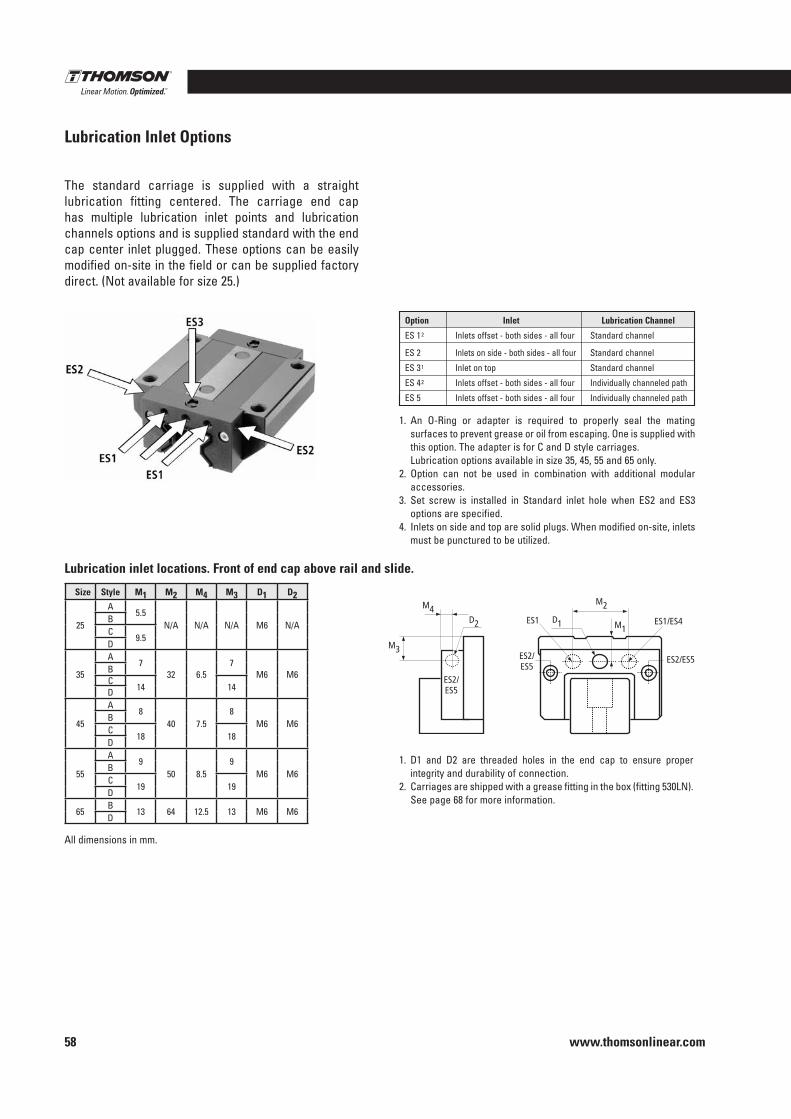
www.thomsonlinear.com58
Lubrication Inlet Options
The standard carriage is supplied with a straight lubri cation fitting centered . The carriage end cap has multiple lubrication inlet points and lubrication channels options and is supplied standard with the end cap center inlet plugged . These options can be easily modified on-site in the field or can be supplied factory direct . (Not available for size 25 .)
1 . An O-Ring or adapter is required to properly seal the mating surfaces to prevent grease or oil from escaping . One is supplied with this option . The adapter is for C and D style carriages .
Lubrication options available in size 35, 45, 55 and 65 only .2 . Option can not be used in combination with additional modular
accessories .3 . Set screw is installed in Standard inlet hole when ES2 and ES3
options are specified .4 . Inlets on side and top are solid plugs . When modified on-site, inlets
must be punctured to be utilized .
Size Style M1 M2 M4 M3 D1 D2
25
A5 .5
N/A N/A N/A M6 N/ABC
9 .5D
35
A7
32 6 .57
M6 M6BC
14 14D
45
A8
40 7 .58
M6 M6BC
18 18D
55
A9
50 8 .59
M6 M6BC
19 19D
65B
13 64 12 .5 13 M6 M6D
Lubrication inlet locations . Front of end cap above rail and slide .
D1
ES2/ ES5
ES2/ ES5
D2
M4
M1
M2
ES2/ES5
ES1
M3
ES1/ES4
1 . D1 and D2 are threaded holes in the end cap to ensure proper integrity and durability of connection .
2 . Carriages are shipped with a grease fitting in the box (fitting 530LN) . See page 68 for more information .
Option Inlet Lubrication Channel
ES 1 2 Inlets offset - both sides - all four Standard channel
ES 2 Inlets on side - both sides - all four Standard channel
ES 3 1 Inlet on top Standard channel
ES 4 2 Inlets offset - both sides - all four Individually channeled path
ES 5 Inlets offset - both sides - all four Individually channeled path
All dimensions in mm .
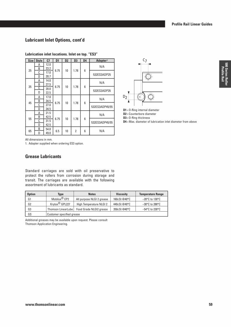
Profile Rail Linear Guides
www.thomsonlinear.com 59
500 Series Roller Profile Rail
D1 = O-Ring internal diameterD2 = Counterbore diameterD3 = O-Ring thicknessD4 = Max . diameter of lubrication inlet diameter from above
C7
D2
Size Style C7 D1 D2 D3 D4
25
A 12 .0 23 .2
6 .75 10 1 .78 6BC 17 .0
20 .7D
35
A 14 .0 27 .5
6 .75 10 1 .78 6BC 20 .0
22 .5D
45
A 17 .0 34 .5
6 .75 10 1 .78 6BC 27 .0
34 .5D
55
A 21 .5 42 .5
6 .75 10 1 .78 6BC 31 .5
42 .5D
65B 54 .0
49 .0 6 .5 10 2 6D
Adapter 1
N/A
532ES3ADP25
N/A
532ES3ADP35
N/A
532ES3ADP45/55
N/A
532ES3ADP45/55
N/A
Lubrication inlet locations . Inlet on top . “ES3”
Lubricant Inlet Options, cont’d
Standard carriages are sold with oil preservative to protect the rollers from corrosion during storage and transit . The carriages are available with the following assortment of lubricants as standard .
Additional greases may be available upon request . Please consult Thomson Application Engineering .
Grease Lubricants
Option Type Notes Viscosity Temperature Range
G1 Mobilux® EP2 All purpose NLGI 2 grease 160cSt @40°C –20°C to 130°C
G2 Krytox® GPL227 High Temperature NLGI 2 440cSt @40°C –30°C to 288°C
G3 Thomson LinearLube Food Grade NLGI2 grease 350cSt @40°C –54°C to 230°C
GS Customer specified grease
All dimensions in mm .1 . Adapter supplied when ordering ES3 option .
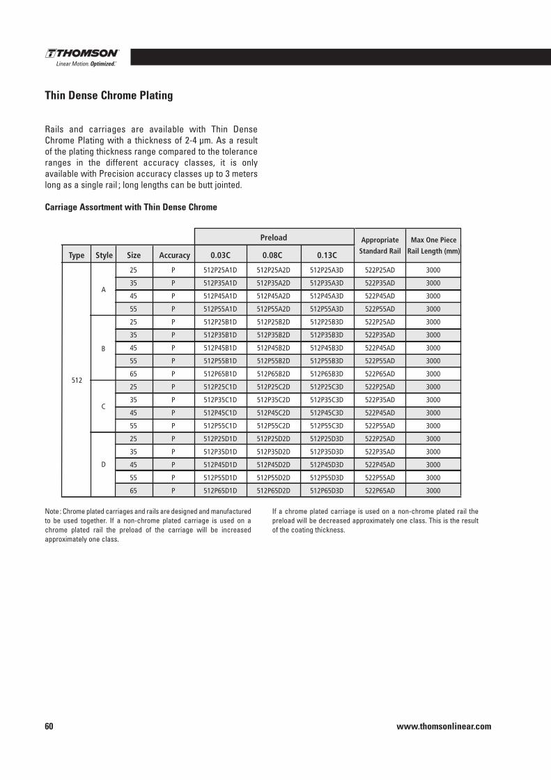
www.thomsonlinear.com60
Thin Dense Chrome Plating
Rails and carriages are available with Thin Dense Chrome Plating with a thickness of 2-4 µm . As a result of the plating thickness range compared to the tolerance ranges in the different accuracy classes, it is only available with Precision accuracy classes up to 3 meters long as a single rail ; long lengths can be butt jointed .
Carriage Assortment with Thin Dense Chrome
A
B
C
D
Type Style Size Accuracy 0.03C 0.08C
Preload Appropriate
Standard Rail
Max One Piece
Rail Length (mm) 0.13C
512
25 P 512P25A1D 512P25A2D 512P25A3D 522P25AD 3000
35 P 512P35A1D 512P35A2D 512P35A3D 522P35AD 3000
45 P 512P45A1D 512P45A2D 512P45A3D 522P45AD 3000
55 P 512P55A1D 512P55A2D 512P55A3D 522P55AD 3000
25 P 512P25B1D 512P25B2D 512P25B3D 522P25AD 3000
35 P 512P35B1D 512P35B2D 512P35B3D 522P35AD 3000
45 P 512P45B1D 512P45B2D 512P45B3D 522P45AD 3000
55 P 512P55B1D 512P55B2D 512P55B3D 522P55AD 3000
65 P 512P65B1D 512P65B2D 512P65B3D 522P65AD 3000
25 P 512P25C1D 512P25C2D 512P25C3D 522P25AD 3000
35 P 512P35C1D 512P35C2D 512P35C3D 522P35AD 3000
45 P 512P45C1D 512P45C2D 512P45C3D 522P45AD 3000
55 P 512P55C1D 512P55C2D 512P55C3D 522P55AD 3000
25 P 512P25D1D 512P25D2D 512P25D3D 522P25AD 3000
35 P 512P35D1D 512P35D2D 512P35D3D 522P35AD 3000
45 P 512P45D1D 512P45D2D 512P45D3D 522P45AD 3000
55 P 512P55D1D 512P55D2D 512P55D3D 522P55AD 3000
65 P 512P65D1D 512P65D2D 512P65D3D 522P65AD 3000
Note : Chrome plated carriages and rails are designed and manufactured to be used together . If a non-chrome plated carriage is used on a chrome plated rail the preload of the carriage will be increased approximately one class .
If a chrome plated carriage is used on a non-chrome plated rail the preload will be decreased approximately one class . This is the result of the coating thickness .
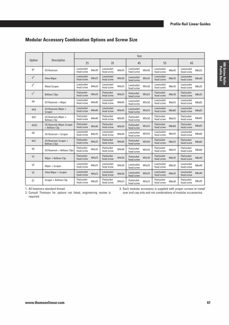
Profile Rail Linear Guides
www.thomsonlinear.com 61
500 Series Roller Profile Rail
Modular Accessory Combination Options and Screw Size
M4x30
M4x25
M4x20
M4x20
M4x40
M4x40
M4x40
M4x40
M4x35
M4x35
M4x35
M4x25
M4x25
M4x25
M4x20
M4x35
M4x30
M4x25
M4x25
M4x45
M4x45
M4x45
M4x50
M4x40
M4x40
M4x40
M4x30
M4x30
M4x30
M4x25
Low/socket head screw
Low/socket head screw
Low/socket head screw
Flat/sockethead screw
Low/socket head screw
Low/socket head screw
Flat/sockethead screw
Flat/sockethead screw
Low/socket head screw
Flat/sockethead screw
Flat/sockethead screw
Flat/sockethead screw
Low/socket head screw
Low/socket head screw
Flat/sockethead screw
M5x45
M5x35
M5x30
M5x25
M5x50
M5x55
M5x50
M5x55
M5x50
M5x50
M5x50
M5x30
M5x35
M5x35
M5x25
Low/socket head screw
Low/socket head screw
Low/socket head screw
Flat/sockethead screw
Low/socket head screw
Low/socket head screw
Flat/sockethead screw
Flat/sockethead screw
Low/socket head screw
Flat/sockethead screw
Flat/sockethead screw
Flat/sockethead screw
Low/socket head screw
Low/socket head screw
Flat/sockethead screw
Low/socket head screw
Low/socket head screw
Low/socket head screw
Flat/sockethead screw
Low/socket head screw
Low/socket head screw
Flat/sockethead screw
Flat/sockethead screw
Low/socket head screw
Flat/sockethead screw
Flat/sockethead screw
Flat/sockethead screw
Low/socket head screw
Low/socket head screw
Flat/sockethead screw
M6x45
M6x35
M6x35
M6x30
M6x55
M6x60
M6x55
M6x60
M6x55
M6x55
M6x55
M6x35
M6x35
M6x35
M6x30
Low/socket head screw
Low/socket head screw
Low/socket head screw
Flat/sockethead screw
Low/socket head screw
Low/socket head screw
Flat/sockethead screw
Flat/sockethead screw
Low/socket head screw
Flat/sockethead screw
Flat/sockethead screw
Flat/sockethead screw
Low/socket head screw
Low/socket head screw
Flat/sockethead screw
M6x55
M6x40
M6x35
M6x35
M6x65
M6x65
M6x65
M6x65
M6x60
M6x60
M6x60
M6x40
M6x40
M6x40
M6x35
Low/socket head screw
Low/socket head screw
Low/socket head screw
Flat/sockethead screw
Low/socket head screw
Low/socket head screw
Flat/sockethead screw
Flat/sockethead screw
Low/socket head screw
Flat/sockethead screw
Flat/sockethead screw
Flat/sockethead screw
Low/socket head screw
Low/socket head screw
Flat/sockethead screw
Oil Reservoir
Viton Wiper
Metal Scraper
Bellows Clips
Oil Reservoir + Wiper
Oil Reservoir, Wiper + Scraper
Oil Reservoir, Wiper + Bellows Clip
Oil Reservoir, Wiper, Scraper + Bellows Clip
Oil Reservoir + Scraper
Oil Reservoir, Scraper + Bellows Clips
Oil Reservoir + Bellows Clips
Wiper + Bellows Clip
Wiper + Scraper
Viton Wiper + Scraper
Scraper + Bellows Clip
N3
V3
Z3
C3
NV
NVZ
NVC
NVZC
NZ
NZC
NC
VC
VZ
VZ
ZC
25 Description Option
35 55 65 45
Size
1 . All fasteners standard thread .2 . Consult Thomson for options not listed, engineering review is
required .
3 . Each modular accessory is supplied with proper screws to install over end cap only and not combinations of modular accessories .
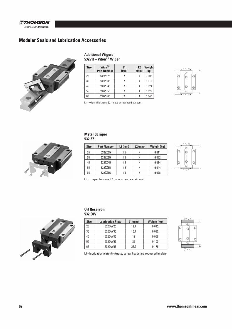
www.thomsonlinear.com62
Modular Seals and Lubrication Accessories
Additional Wipers532VR – Viton® Wiper
Metal Scraper532 ZZ
L1 – wiper thickness, L2 – max . screw head stickout
Oil Reservoir532 OW
L2 L1
L2 L1
L2 L1
L2 L1
Size Viton® L1 L2 Weight Part Number (mm) (mm) (kg)
25 532VR25 7 4 0 .005
35 532VR35 7 4 0 .012
45 532VR45 7 4 0 .024
55 532VR55 7 4 0 .029
65 532VR65 7 4 0 .040
L1 = scraper thickness, L2 = max . screw head stickout
Size Part Number L1 (mm) L2 (mm) Weight (kg)
25 532ZZ25 1 .5 4 0 .011
35 532ZZ35 1 .5 4 0 .022
45 532ZZ45 1 .5 4 0 .034
55 532ZZ55 1 .5 4 0 .044
65 532ZZ65 1 .5 4 0 .078
L1 = lubrication plate thickness, screw heads are recessed in plate
Size Lubrication Plate L1 (mm) Weight (kg)25 532OW25 12 .7 0 .013
35 532OW35 16 .7 0 .032
45 532OW45 19 0 .056
55 532OW55 22 0 .103
65 532OW65 25 .2 0 .179
L1
L1
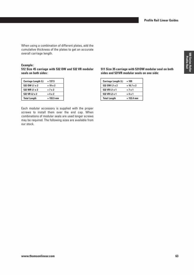
Profile Rail Linear Guides
www.thomsonlinear.com 63
500 Series Roller Profile Rail
When using a combination of different plates, add the cumulative thickness of the plates to get an accurate overall carriage length .
Example :512 Size 45 carriage with 532 OW and 532 VR modular seals on both sides :
Each modular accessory is supplied with the proper screws to install them over the end cap . When combinations of modular seals are used longer screws may be required . The following sizes are available from our stock .
511 Size 35 carriage with 531OW modular seal on both sides and 531VR modular seals on one side:
Carriage Length (L) = 137 .5
532 OW L1 x 2 = 19 x 2
532 WR L1 x 2 = 7 x 2
532 VR L2 x 2 = 4 x 2
Total Length = 193 .5 mm
Carriage Length (L) = 109
532 OW L1 x 2 = 16 .7 x 2
532 VR L1 x 1 = 7 x 1
532 VR L2 x 1 = 4 x 1
Total Length = 153 .4 mm
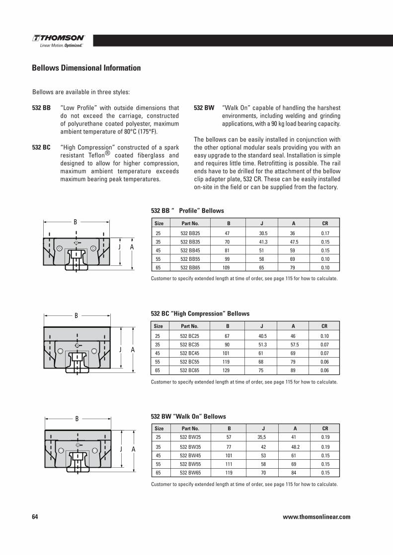
www.thomsonlinear.com64
Bellows Dimensional Information
Bellows are available in three styles:
532 BB “Low Profile” with outside dimensions that do not exceed the carriage, constructed of polyurethane coated polyester, maximum ambient temperature of 80°C (175°F) .
532 BC “High Compression” constructed of a spark resistant Teflon® coated fiberglass and designed to allow for higher compression, maximum ambient temperature exceeds maximum bearing peak temperatures .
532 BW “Walk On” capable of handling the harshest environments, including welding and grinding applications, with a 90 kg load bearing capacity .
The bellows can be easily installed in conjunction with the other optional modular seals providing you with an easy upgrade to the standard seal . Installation is simple and requires little time . Retrofitting is possible . The rail ends have to be drilled for the attachment of the bellow clip adapter plate, 532 CR . These can be easily installed on-site in the field or can be supplied from the factory .
Customer to specify extended length at time of order, see page 115 for how to calculate .
Customer to specify extended length at time of order, see page 115 for how to calculate .
Size Part No . B J A CR
25 532 BC25 67 40 .5 46 0 .10
35 532 BC35 90 51 .3 57 .5 0 .07
45 532 BC45 101 61 69 0 .07
55 532 BC55 119 68 79 0 .06
65 532 BC65 129 75 89 0 .06
Customer to specify extended length at time of order, see page 115 for how to calculate .
Size Part No . B J A CR
25 532 BW25 57 35,5 41 0 .19
35 532 BW35 77 42 48 .2 0 .19
45 532 BW45 101 53 61 0 .15
55 532 BW55 111 58 69 0 .15
65 532 BW65 119 70 84 0 .15
532 BB “ Profile” Bellows
532 BC “High Compression” Bellows
532 BW “Walk On” Bellows
Size Part No . B J A CR
25 532 BB25 47 30 .5 36 0 .17
35 532 BB35 70 41 .3 47 .5 0 .15
45 532 BB45 81 51 59 0 .15
55 532 BB55 99 58 69 0 .10
65 532 BB65 109 65 79 0 .10
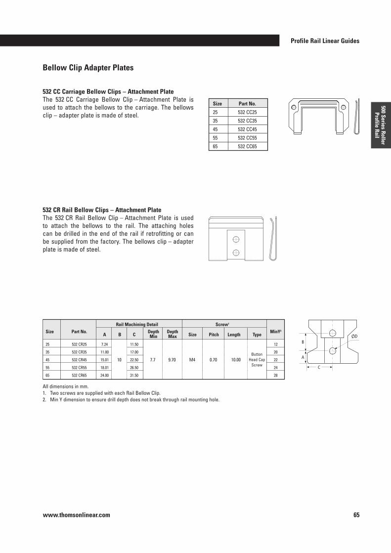
Profile Rail Linear Guides
www.thomsonlinear.com 65
500 Series Roller Profile Rail
Bellow Clip Adapter Plates
532 CR Rail Bellow Clips – Attachment PlateThe 532 CR Rail Bellow Clip – Attachment Plate is used to attach the bellows to the rail . The attaching holes can be drilled in the end of the rail if retrofitting or can be supplied from the factory . The bellows clip – adapter plate is made of steel .
All dimensions in mm .1 . Two screws are supplied with each Rail Bellow Clip . 2 . Min Y dimension to ensure drill depth does not break through rail mounting hole .
532 CC Carriage Bellow Clips – Attachment PlateThe 532 CC Carriage Bellow Clip – Attachment Plate is used to attach the bellows to the carriage . The bellows clip – adapter plate is made of steel .
Size Part No .
25 532 CC25
35 532 CC35
45 532 CC45
55 532 CC55
65 532 CC65
Rail Machining Detail Screw1
Size Part No . A B C
Depth Depth Size Pitch Length Type
MinY2 Min Max
25 532 CR25 7 .24 11 .50 12
35 532 CR35 11 .00 17 .00 20
45 532 CR45 15 .01 22 .50 22
55 532 CR55 18 .01 26 .50 24
65 532 CR65 24 .00 31 .50 28
7 .710 9 .70 M4 0 .70 10 .00Button
Head CapScrew
B
A
C
D
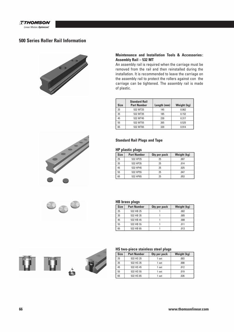
www.thomsonlinear.com66
500 Series Roller Rail Information
Maintenance and Installation Tools & Accessories : Assembly Rail – 532 MTAn assembly rail is required when the carriage must be removed from the rail and then reinstalled during the installation . It is recommended to leave the carriage on the assembly rail to protect the rollers against con the carriage can be tightened . The assembly rail is made of plastic .
Standard Rail Plugs and Tape
HP plastic plugs
HB brass plugs
HS two-piece stainless steel plugs
Standard Rail Size Part Number Length (mm) Weight (kg)25 532 MT25 145 0 .062
35 532 MT35 185 0 .152
45 532 MT45 230 0 .317
55 532 MT55 265 0 .525
65 532 MT65 320 0 .914
Size Part Number Qty per pack Weight (kg)25 532 HP25 25 .007
35 532 HP35 25 .014
45 532 HP45 25 .025
55 532 HP55 25 .047
65 532 HP65 25 .053
Size Part Number Qty per pack Weight (kg)25 532 HB 25 1 .002
35 532 HB 35 1 .005
45 532 HB 45 1 .008
55 532 HB 55 1 .011
65 532 HB 65 1 .013
Size Part Number Qty per pack Weight (kg)25 532 HS 25 1 set .003
35 532 HS 35 1 set .008
45 532 HS 45 1 set .012
55 532 HS 55 1 set .019
65 532 HS 65 1 set .026
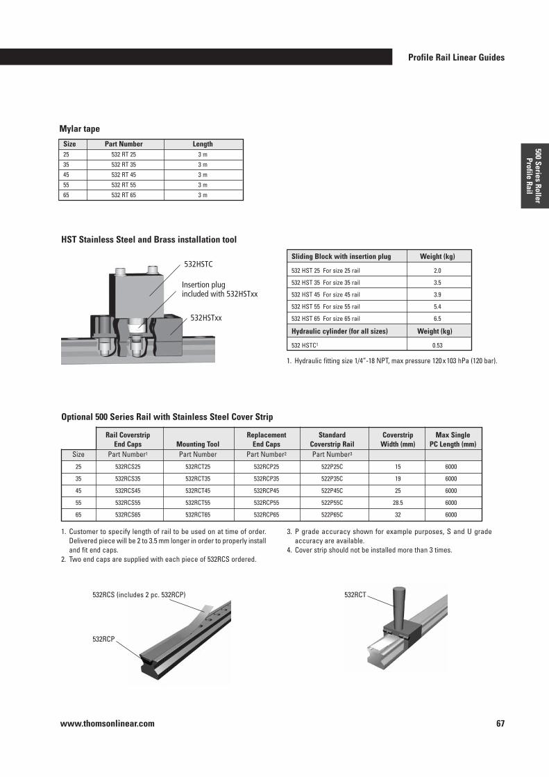
Profile Rail Linear Guides
www.thomsonlinear.com 67
500 Series Roller Profile Rail
Rail Coverstrip Replacement Standard Coverstrip Max Single End Caps Mounting Tool End Caps Coverstrip Rail Width (mm) PC Length (mm) Size Part Number1 Part Number Part Number2 Part Number3
25 532RCS25 532RCT25 532RCP25 522P25C 15 6000
35 532RCS35 532RCT35 532RCP35 522P35C 19 6000
45 532RCS45 532RCT45 532RCP45 522P45C 25 6000
55 532RCS55 532RCT55 532RCP55 522P55C 28 .5 6000
65 532RCS65 532RCT65 532RCP65 522P65C 32 6000
Mylar tape
HST Stainless Steel and Brass installation tool
1 . Customer to specify length of rail to be used on at time of order . Delivered piece will be 2 to 3 .5 mm longer in order to properly install and fit end caps .
2 . Two end caps are supplied with each piece of 532RCS ordered .
3 . P grade accuracy shown for example purposes, S and U grade accuracy are available .
4 . Cover strip should not be installed more than 3 times .
Optional 500 Series Rail with Stainless Steel Cover Strip
532RCS (includes 2 pc . 532RCP)
532RCP
532RCT
Size Part Number Length25 532 RT 25 3 m
35 532 RT 35 3 m
45 532 RT 45 3 m
55 532 RT 55 3 m
65 532 RT 65 3 m
1 . Hydraulic fitting size 1/4”-18 NPT, max pressure 120 x 103 hPa (120 bar) .
532HSTC
Insertion plug included with 532HSTxx
532HSTxx
Sliding Block with insertion plug Weight (kg)
532 HST 25 For size 25 rail 2 .0
532 HST 35 For size 35 rail 3 .5
532 HST 45 For size 45 rail 3 .9
532 HST 55 For size 55 rail 5 .4
532 HST 65 For size 65 rail 6 .5
Hydraulic cylinder (for all sizes) Weight (kg)
532 HSTC1 0 .53
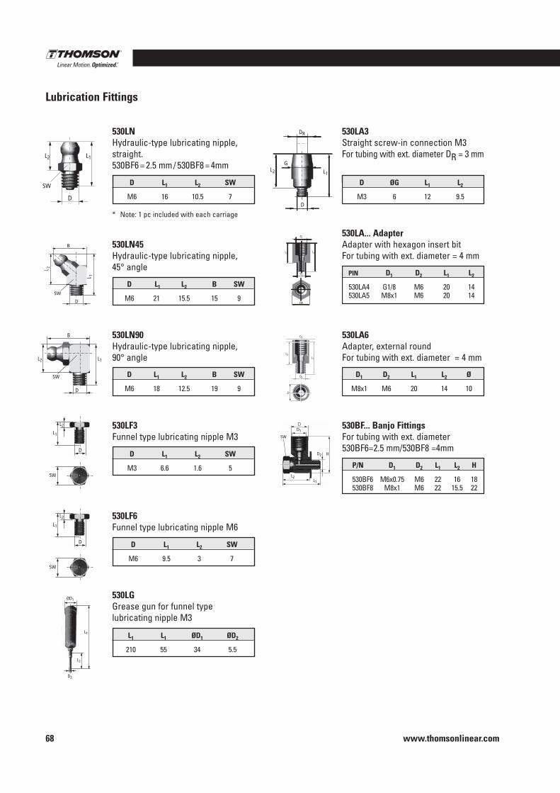
www.thomsonlinear.com68
Lubrication Fittings
PIN D1 D2 L1 L2
530LA4 G1/8 M6 20 14 530LA5 M8x1 M6 20 14
530LA . . . Adapter Adapter with hexagon insert bitFor tubing with ext . diameter = 4 mm
D ØG L1 L2
M3 6 12 9 .5
530LA3 Straight screw-in connection M3For tubing with ext . diameter DR = 3 mm
L1 L1 ØD1 ØD2
210 55 34 5 .5
530LG Grease gun for funnel type lubricating nipple M3
D L1 L2 SW
M6 9 .5 3 7
530LF6 Funnel type lubricating nipple M6
D L1 L2 B SW
M6 21 15 .5 15 9
530LN45 Hydraulic-type lubricating nipple, 45° angle
D L1 L2 SW
M6 16 10 .5 7
530LNHydraulic-type lubricating nipple, straight .530BF6 = 2 .5 mm / 530BF8 = 4mm
D1 D2 L1 L2 Ø
M8x1 M6 20 14 10
530LA6 Adapter, external roundFor tubing with ext . diameter = 4 mm
L2 L1
D1
D2
SW
L2 L1
DR
G
D
L2 L1
D1
D2
D
D L1 L2 SW
M3 6 .6 1 .6 5
530LF3 Funnel type lubricating nipple M3
ØD1
D2
L2
L1
L 1
B
SW
D
L 2
D
L2 L1
SW
D
L2
L1
SW
D
B
L2 L1
SW D L1 L2 B SW
M6 18 12 .5 19 9
530LN90 Hydraulic-type lubricating nipple, 90° angle
* Note: 1 pc included with each carriage
530BF . . . Banjo Fittings For tubing with ext . diameter530BF6=2 .5 mm/530BF8 =4mm
P/N D1 D2 L1 L2 H
530BF6 M6x0 .75 M6 22 16 18 530BF8 M8x1 M6 22 15 .5 22
D
L2
L1
SW
D
L2L1
D1
D2 H
SW
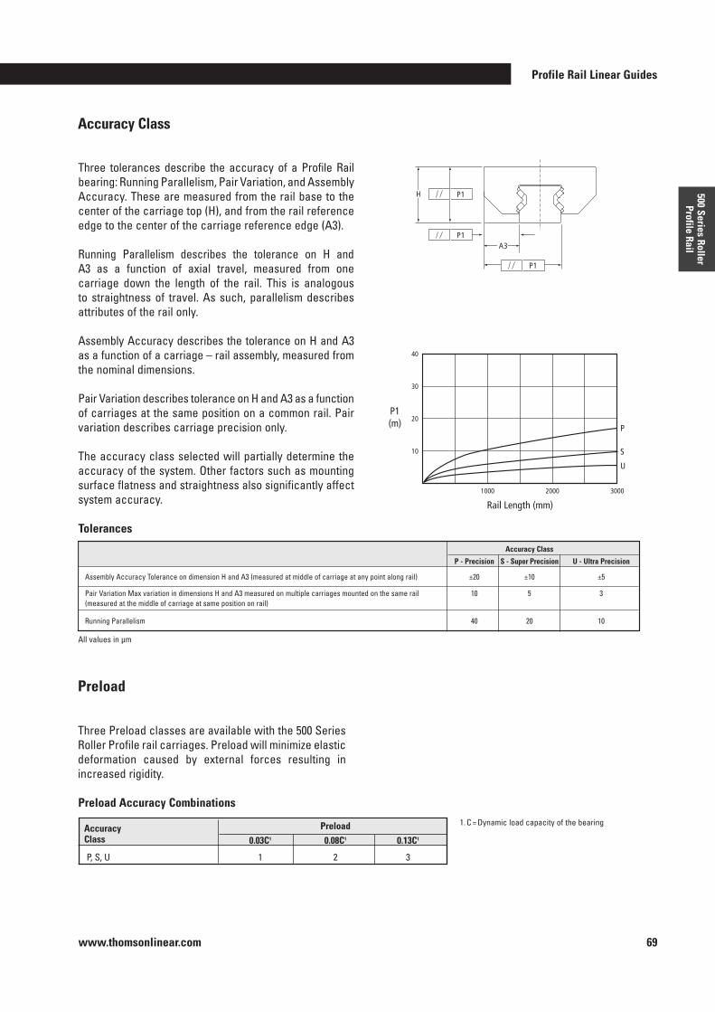
Profile Rail Linear Guides
www.thomsonlinear.com 69
500 Series Roller Profile Rail
Accuracy Class
A3
H
P1
P1
P1
Rail Length (mm)
P1 (m) P
S
U
1000
10
20
30
40
2000 3000
Preload
Three Preload classes are available with the 500 Series Roller Profile rail carriages . Preload will minimize elastic deformation caused by external forces resulting in increased rigidity .
Preload Accuracy Combinations
Three tolerances describe the accuracy of a Profile Rail bearing: Running Parallelism, Pair Variation, and Assembly Accuracy . These are measured from the rail base to the center of the carriage top (H), and from the rail reference edge to the center of the carriage reference edge (A3) .
Running Parallelism describes the tolerance on H and A3 as a function of axial travel, measured from one carriage down the length of the rail . This is analogous to straightness of travel . As such, parallelism describes attributes of the rail only .
Assembly Accuracy describes the tolerance on H and A3 as a function of a carriage – rail assembly, measured from the nominal dimensions .
Pair Variation describes tolerance on H and A3 as a function of carriages at the same position on a common rail . Pair variation describes carriage precision only .
The accuracy class selected will partially determine the accuracy of the system . Other factors such as mounting surface flatness and straightness also significantly affect system accuracy .
Tolerances
1 . C = Dynamic load capacity of the bearingAccuracy Preload Class 0 .03C1 0 .08C1 0 .13C1
P, S, U 1 2 3
All values in µm
Accuracy Class
P - Precision S - Super Precision U - Ultra Precision Assembly Accuracy Tolerance on dimension H and A3 (measured at middle of carriage at any point along rail) ±20 ±10 ±5
Pair Variation Max variation in dimensions H and A3 measured on multiple carriages mounted on the same rail 10 5 3 (measured at the middle of carriage at same position on rail)
Running Parallelism 40 20 10
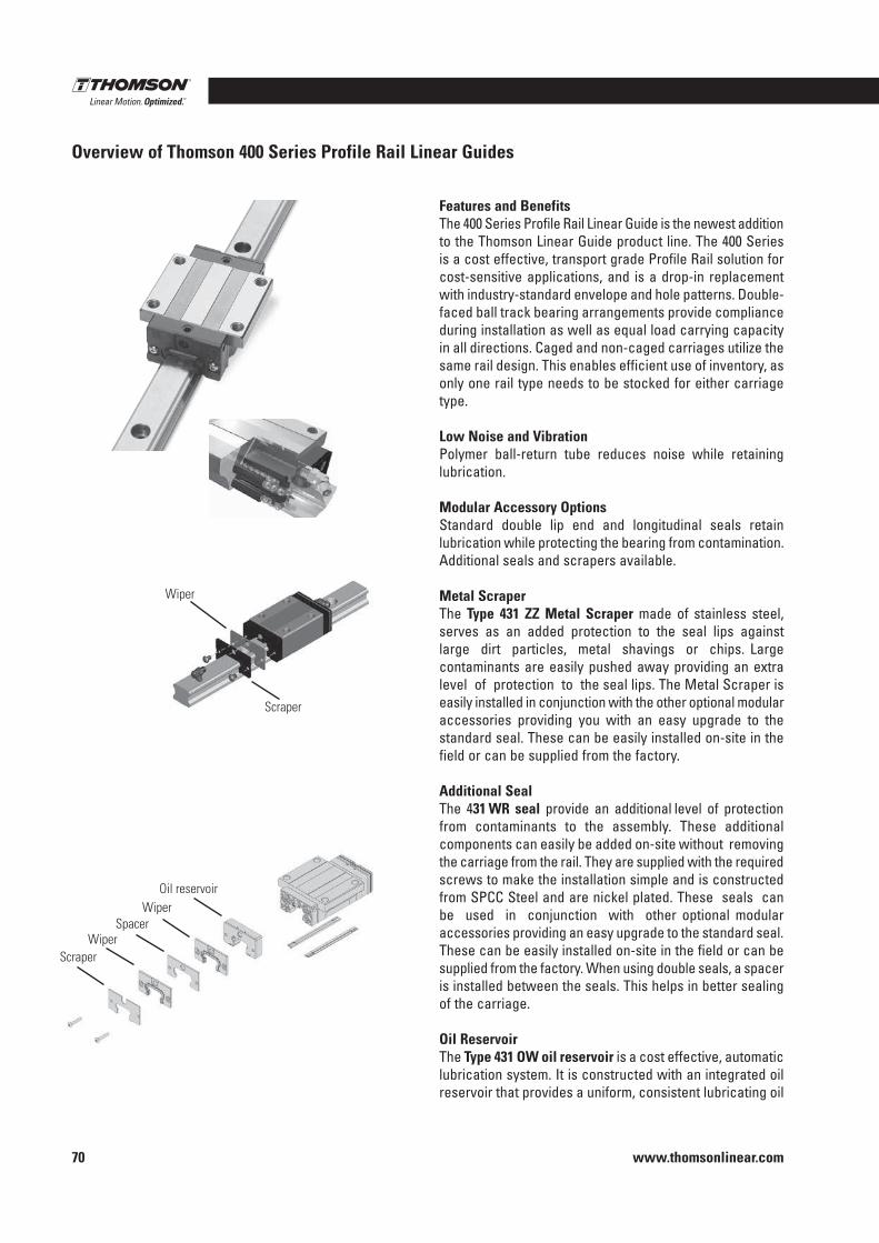
www.thomsonlinear.com70
Overview of Thomson 400 Series Profile Rail Linear Guides
Wiper
Scraper
Features and BenefitsThe 400 Series Profile Rail Linear Guide is the newest addition to the Thomson Linear Guide product line . The 400 Series is a cost effective, transport grade Profile Rail solution for cost-sensitive applications, and is a drop-in replacement with industry-standard envelope and hole patterns . Double-faced ball track bearing arrangements provide compliance during installation as well as equal load carrying capacity in all directions . Caged and non-caged carriages utilize the same rail design . This enables efficient use of inventory, as only one rail type needs to be stocked for either carriage type .
Low Noise and VibrationPolymer ball-return tube reduces noise while retaining lubrication .
Modular Accessory Options Standard double lip end and longitudinal seals retain lubrication while protecting the bearing from contamination . Additional seals and scrapers available .
Metal ScraperThe Type 431 ZZ Metal Scraper made of stainless steel, serves as an added protection to the seal lips against large dirt particles, metal shavings or chips . Large contaminants are easily pushed away providing an extra level of protection to the seal lips . The Metal Scraper is easily installed in conjunction with the other optional modular accessories providing you with an easy upgrade to the standard seal . These can be easily installed on-site in the field or can be supplied from the factory .
Additional SealThe 431 WR seal provide an additional level of protection from contaminants to the assembly . These additional components can easily be added on-site without removing the carriage from the rail . They are supplied with the required screws to make the installation simple and is constructed from SPCC Steel and are nickel plated . These seals can be used in conjunction with other optional modular accessories providing an easy upgrade to the standard seal . These can be easily installed on-site in the field or can be supplied from the factory . When using double seals, a spacer is installed between the seals . This helps in better sealing of the carriage .
Oil ReservoirThe Type 431 OW oil reservoir is a cost effective, automatic lubrication system . It is constructed with an integrated oil reservoir that provides a uniform, consistent lubricating oil
Oil reservoirWiper
WiperSpacer
Scraper
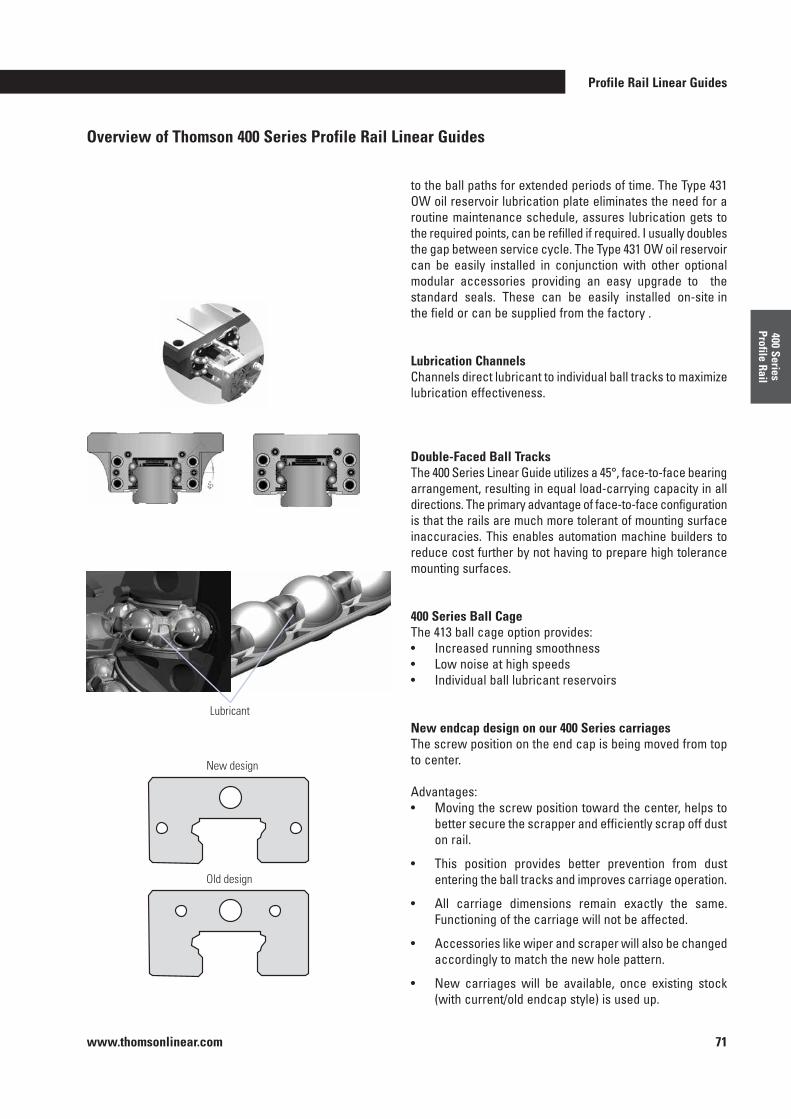
Profile Rail Linear Guides
www.thomsonlinear.com 71
400 Series Profile Rail
Overview of Thomson 400 Series Profile Rail Linear Guides
New design
Old design
Lubricant
to the ball paths for extended periods of time . The Type 431 OW oil reservoir lubrication plate eliminates the need for a routine maintenance schedule, assures lubrication gets to the required points, can be refilled if required . I usually doubles the gap between service cycle . The Type 431 OW oil reservoir can be easily installed in conjunction with other optional modular accessories providing an easy upgrade to the standard seals . These can be easily installed on-site in the field or can be supplied from the factory .
Lubrication ChannelsChannels direct lubricant to individual ball tracks to maximize lubrication effectiveness .
Double-Faced Ball TracksThe 400 Series Linear Guide utilizes a 45°, face-to-face bearing arrangement, resulting in equal load-carrying capacity in all directions . The primary advantage of face-to-face configuration is that the rails are much more tolerant of mounting surface inaccuracies . This enables automation machine builders to reduce cost further by not having to prepare high tolerance mounting surfaces .
400 Series Ball CageThe 413 ball cage option provides:• Increased running smoothness• Low noise at high speeds• Individual ball lubricant reservoirs
New endcap design on our 400 Series carriagesThe screw position on the end cap is being moved from top to center .
Advantages:• Moving the screw position toward the center, helps to
better secure the scrapper and efficiently scrap off dust on rail .
• This position provides better prevention from dust entering the ball tracks and improves carriage operation .
• All carriage dimensions remain exactly the same . Functioning of the carriage will not be affected .
• Accessories like wiper and scraper will also be changed accordingly to match the new hole pattern .
• New carriages will be available, once existing stock (with current/old endcap style) is used up .
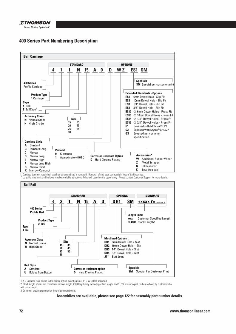
www.thomsonlinear.com72
400 Series Part Numbering Description
StandardSTANDARD OPTIONS
Ball Carriage
400 SeriesProfile Carriage
Product Type1 Carriage
4 1 1 N 15 A 0 ES1 SMW ZD
SpecialsSM Special per customer print
Extended Standards - Options ES1 6mm Dowel Hole - Slip FitES2 10mm Dowel Hole - Slip FitES3 1/4” Dowel Hole - Slip FitES4 3/8” Dowel Hole - Slip FitES12 (2) 6mm Dowel Holes - Press FitES13 (2) 10mm Dowel Holes - Press Fit ES14 (2) 1/4” Dowel Holes - Press FitES15 (2) 3/8” Dowel Holes - Press FitG1 Greased with Mobilux® EP2 G2 Greased with Krytox® GPL227 GS Greased per customer
specification
Accuracy ClassN Normal GradeH High Grade
Size152025
Carriage StyleA StandardB Standard LongC NarrowD Narrow LongE Narrow HighF Narrow Long HighG Narrow ShortK Narrow Compact
Preload0 Clearance1 Approximately 0.03 C
Type1 Ball
Accessories*W Additional Rubber WiperZ Metal Scraper
Corrosion-resistant OptionD Hard Chrome Plating
3 Ball Cage1
30
3545
1. Carriage does not retain ball bearings when end cap is removed. Removal of end caps can result in loss of ball bearings.2. Carriage dynamic load ratings based on a travel life of 50 km.
55
OPTIONSSTANDARD STANDARD
Ball Rail
400 SeriesProfile Rail
Product Type2 Rail
4 2 1 N 15 A D SM +xxxx Y= (see note 1)DH1
Length (mm)xxxx Customer Specified Length RL4000 Stock Length2
SpecialsSM Special Per Customer Print
Machined Options DH1 6mm Dowel Hole + Slot DH2 10mm Dowel Hole + Slot DH3 1⁄4” Dowel Hole + Slot DH4 3⁄8” Dowel Hole + Slot JT3 Butt Joint
Accuracy ClassN Normal GradeH High Grade
Size152025
Rail StyleA StandardU Bolt up from Bottom
Corrosion-resistant optionD Hard Chrome Plating
Type1 Ball
30
3545
1. Y = Distance from end of rail to center of first mounting hole, Y1 = Y2 unless specified.2. Stock length of rails are considered random length, total length may exceed specified length, and Y1/Y2 are not equal. To be used only by customer who will cut to length.3. Customer drawing required at time of quote and order.
55
* Long life lube block and bellows may be available as options if desired, based on the opportunity. Please contact Customer Support for more details.
Assemblies are available, please see page 122 for assembly part number details .
N Oil ReservoirK Low drag seal
Assemblies are available, please see page 122 for assembly part number details .
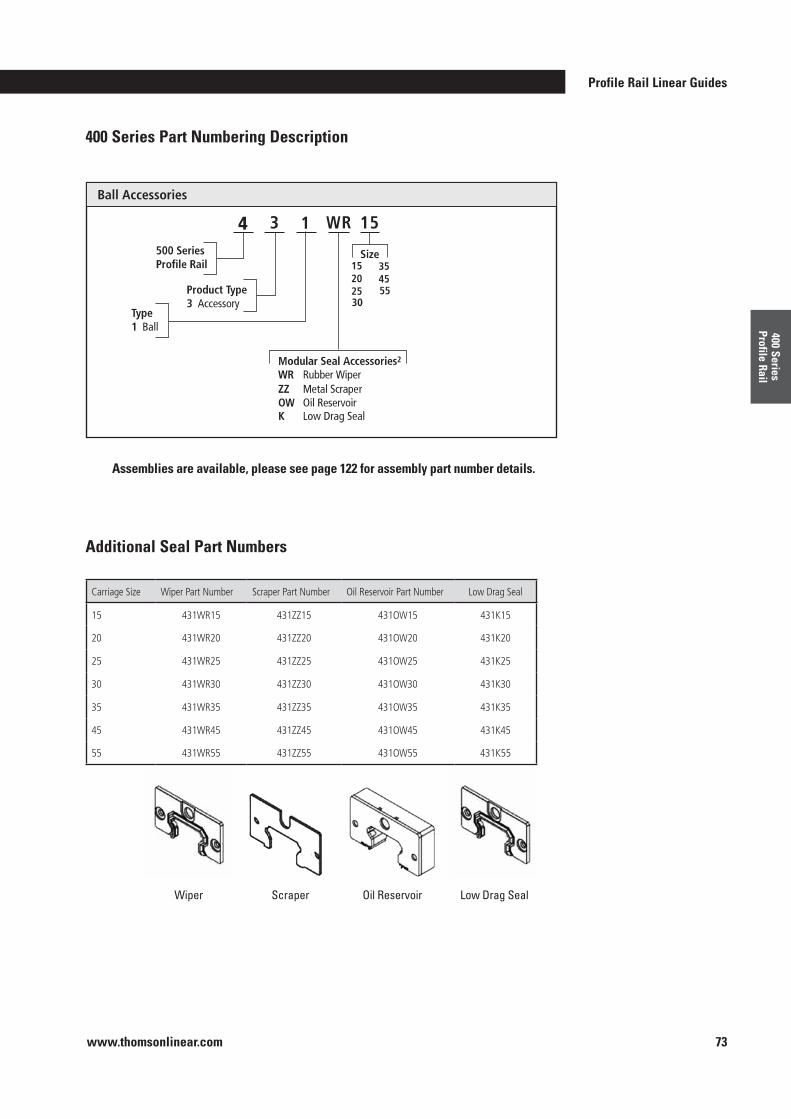
Profile Rail Linear Guides
www.thomsonlinear.com 73
400 Series Profile Rail
400 Series Part Numbering Description
Additional Seal Part Numbers
Assemblies are available, please see page 122 for assembly part number details .
Wiper Scraper Oil Reservoir Low Drag Seal
Carriage Size Wiper Part Number Scraper Part Number Oil Reservoir Part Number Low Drag Seal
15 431WR15 431ZZ15 431OW15 431K15
20 431WR20 431ZZ20 431OW20 431K20
25 431WR25 431ZZ25 431OW25 431K25
30 431WR30 431ZZ30 431OW30 431K30
35 431WR35 431ZZ35 431OW35 431K35
45 431WR45 431ZZ45 431OW45 431K45
55 431WR55 431ZZ55 431OW55 431K55
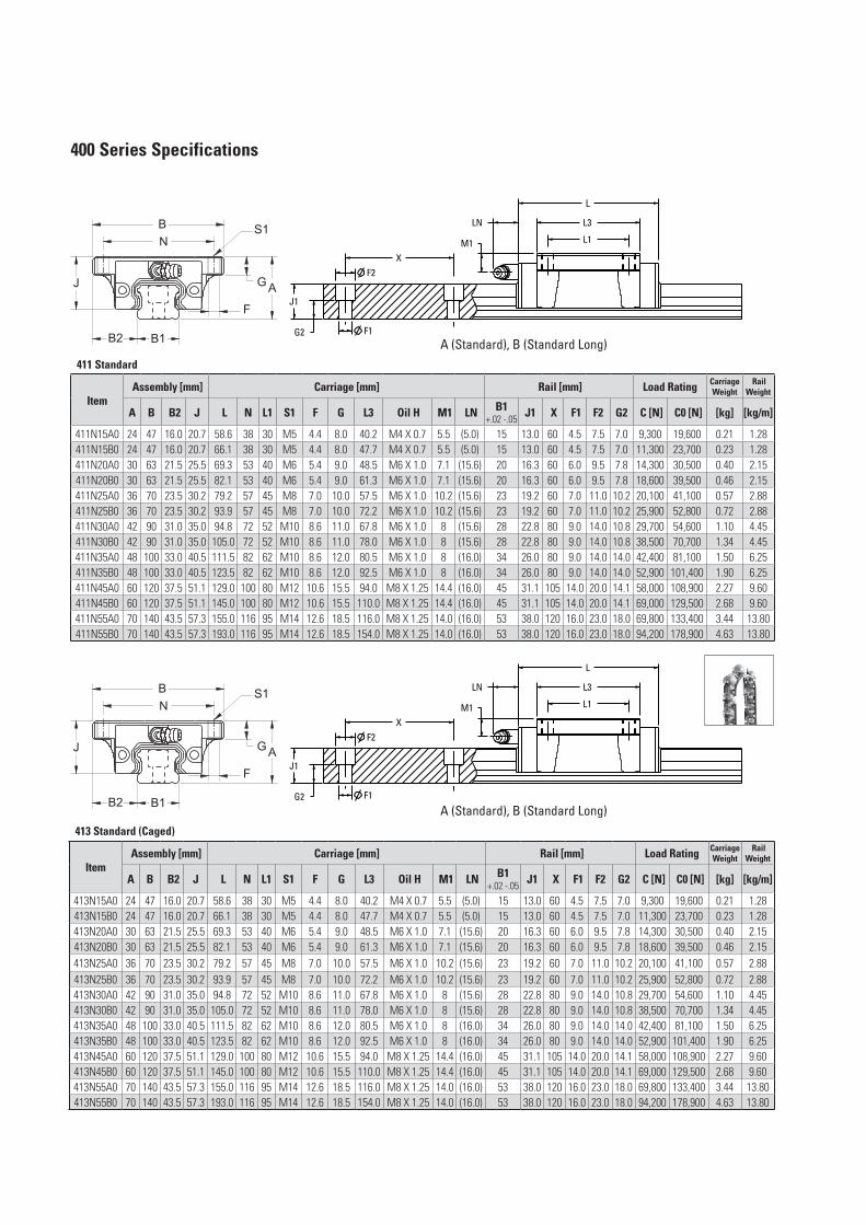
400 Series Specifications
411 Standard
Item Assembly [mm] Carriage [mm] Rail [mm] Load Rating Carriage
Weight Rail
Weight
A B B2 J L N L1 S1 F G L3 Oil H M1 LN B1+.02 -.05 J1 X F1 F2 G2 C [N] C0 [N] [kg] [kg/m]
411N15A0 24 47 16.0 20.7 58.6 38 30 M5 4.4 8.0 40.2 M4 X 0.7 5.5 (5.0) 15 13.0 60 4.5 7.5 7.0 9,300 19,600 0.21 1.28411N15B0 24 47 16.0 20.7 66.1 38 30 M5 4.4 8.0 47.7 M4 X 0.7 5.5 (5.0) 15 13.0 60 4.5 7.5 7.0 11,300 23,700 0.23 1.28411N20A0 30 63 21.5 25.5 69.3 53 40 M6 5.4 9.0 48.5 M6 X 1.0 7.1 (15.6) 20 16.3 60 6.0 9.5 7.8 14,300 30,500 0.40 2.15411N20B0 30 63 21.5 25.5 82.1 53 40 M6 5.4 9.0 61.3 M6 X 1.0 7.1 (15.6) 20 16.3 60 6.0 9.5 7.8 18,600 39,500 0.46 2.15411N25A0 36 70 23.5 30.2 79.2 57 45 M8 7.0 10.0 57.5 M6 X 1.0 10.2 (15.6) 23 19.2 60 7.0 11.0 10.2 20,100 41,100 0.57 2.88411N25B0 36 70 23.5 30.2 93.9 57 45 M8 7.0 10.0 72.2 M6 X 1.0 10.2 (15.6) 23 19.2 60 7.0 11.0 10.2 25,900 52,800 0.72 2.88411N30A0 42 90 31.0 35.0 94.8 72 52 M10 8.6 11.0 67.8 M6 X 1.0 8 (15.6) 28 22.8 80 9.0 14.0 10.8 29,700 54,600 1.10 4.45411N30B0 42 90 31.0 35.0 105.0 72 52 M10 8.6 11.0 78.0 M6 X 1.0 8 (15.6) 28 22.8 80 9.0 14.0 10.8 38,500 70,700 1.34 4.45411N35A0 48 100 33.0 40.5 111.5 82 62 M10 8.6 12.0 80.5 M6 X 1.0 8 (16.0) 34 26.0 80 9.0 14.0 14.0 42,400 81,100 1.50 6.25411N35B0 48 100 33.0 40.5 123.5 82 62 M10 8.6 12.0 92.5 M6 X 1.0 8 (16.0) 34 26.0 80 9.0 14.0 14.0 52,900 101,400 1.90 6.25411N45A0 60 120 37.5 51.1 129.0 100 80 M12 10.6 15.5 94.0 M8 X 1.25 14.4 (16.0) 45 31.1 105 14.0 20.0 14.1 58,000 108,900 2.27 9.60411N45B0 60 120 37.5 51.1 145.0 100 80 M12 10.6 15.5 110.0 M8 X 1.25 14.4 (16.0) 45 31.1 105 14.0 20.0 14.1 69,000 129,500 2.68 9.60411N55A0 70 140 43.5 57.3 155.0 116 95 M14 12.6 18.5 116.0 M8 X 1.25 14.0 (16.0) 53 38.0 120 16.0 23.0 18.0 69,800 133,400 3.44 13.80411N55B0 70 140 43.5 57.3 193.0 116 95 M14 12.6 18.5 154.0 M8 X 1.25 14.0 (16.0) 53 38.0 120 16.0 23.0 18.0 94,200 178,900 4.63 13.80
413 Standard (Caged)
Item Assembly [mm] Carriage [mm] Rail [mm] Load Rating Carriage
Weight Rail
Weight
A B B2 J L N L1 S1 F G L3 Oil H M1 LN B1+.02 -.05 J1 X F1 F2 G2 C [N] C0 [N] [kg] [kg/m]
413N15A0 24 47 16.0 20.7 58.6 38 30 M5 4.4 8.0 40.2 M4 X 0.7 5.5 (5.0) 15 13.0 60 4.5 7.5 7.0 9,300 19,600 0.21 1.28413N15B0 24 47 16.0 20.7 66.1 38 30 M5 4.4 8.0 47.7 M4 X 0.7 5.5 (5.0) 15 13.0 60 4.5 7.5 7.0 11,300 23,700 0.23 1.28413N20A0 30 63 21.5 25.5 69.3 53 40 M6 5.4 9.0 48.5 M6 X 1.0 7.1 (15.6) 20 16.3 60 6.0 9.5 7.8 14,300 30,500 0.40 2.15413N20B0 30 63 21.5 25.5 82.1 53 40 M6 5.4 9.0 61.3 M6 X 1.0 7.1 (15.6) 20 16.3 60 6.0 9.5 7.8 18,600 39,500 0.46 2.15413N25A0 36 70 23.5 30.2 79.2 57 45 M8 7.0 10.0 57.5 M6 X 1.0 10.2 (15.6) 23 19.2 60 7.0 11.0 10.2 20,100 41,100 0.57 2.88413N25B0 36 70 23.5 30.2 93.9 57 45 M8 7.0 10.0 72.2 M6 X 1.0 10.2 (15.6) 23 19.2 60 7.0 11.0 10.2 25,900 52,800 0.72 2.88413N30A0 42 90 31.0 35.0 94.8 72 52 M10 8.6 11.0 67.8 M6 X 1.0 8 (15.6) 28 22.8 80 9.0 14.0 10.8 29,700 54,600 1.10 4.45413N30B0 42 90 31.0 35.0 105.0 72 52 M10 8.6 11.0 78.0 M6 X 1.0 8 (15.6) 28 22.8 80 9.0 14.0 10.8 38,500 70,700 1.34 4.45413N35A0 48 100 33.0 40.5 111.5 82 62 M10 8.6 12.0 80.5 M6 X 1.0 8 (16.0) 34 26.0 80 9.0 14.0 14.0 42,400 81,100 1.50 6.25413N35B0 48 100 33.0 40.5 123.5 82 62 M10 8.6 12.0 92.5 M6 X 1.0 8 (16.0) 34 26.0 80 9.0 14.0 14.0 52,900 101,400 1.90 6.25413N45A0 60 120 37.5 51.1 129.0 100 80 M12 10.6 15.5 94.0 M8 X 1.25 14.4 (16.0) 45 31.1 105 14.0 20.0 14.1 58,000 108,900 2.27 9.60413N45B0 60 120 37.5 51.1 145.0 100 80 M12 10.6 15.5 110.0 M8 X 1.25 14.4 (16.0) 45 31.1 105 14.0 20.0 14.1 69,000 129,500 2.68 9.60413N55A0 70 140 43.5 57.3 155.0 116 95 M14 12.6 18.5 116.0 M8 X 1.25 14.0 (16.0) 53 38.0 120 16.0 23.0 18.0 69,800 133,400 3.44 13.80413N55B0 70 140 43.5 57.3 193.0 116 95 M14 12.6 18.5 154.0 M8 X 1.25 14.0 (16.0) 53 38.0 120 16.0 23.0 18.0 94,200 178,900 4.63 13.80
A (Standard), B (Standard Long)
A (Standard), B (Standard Long)
N
B
AJ G
B2
XF2
F1G2
J1
L1
L3
L
M1
B1
LN
F
S1
N
B
AJ G
B2
XF2
F1G2
J1
L1
L3
L
M1
B1
LN
F
S1
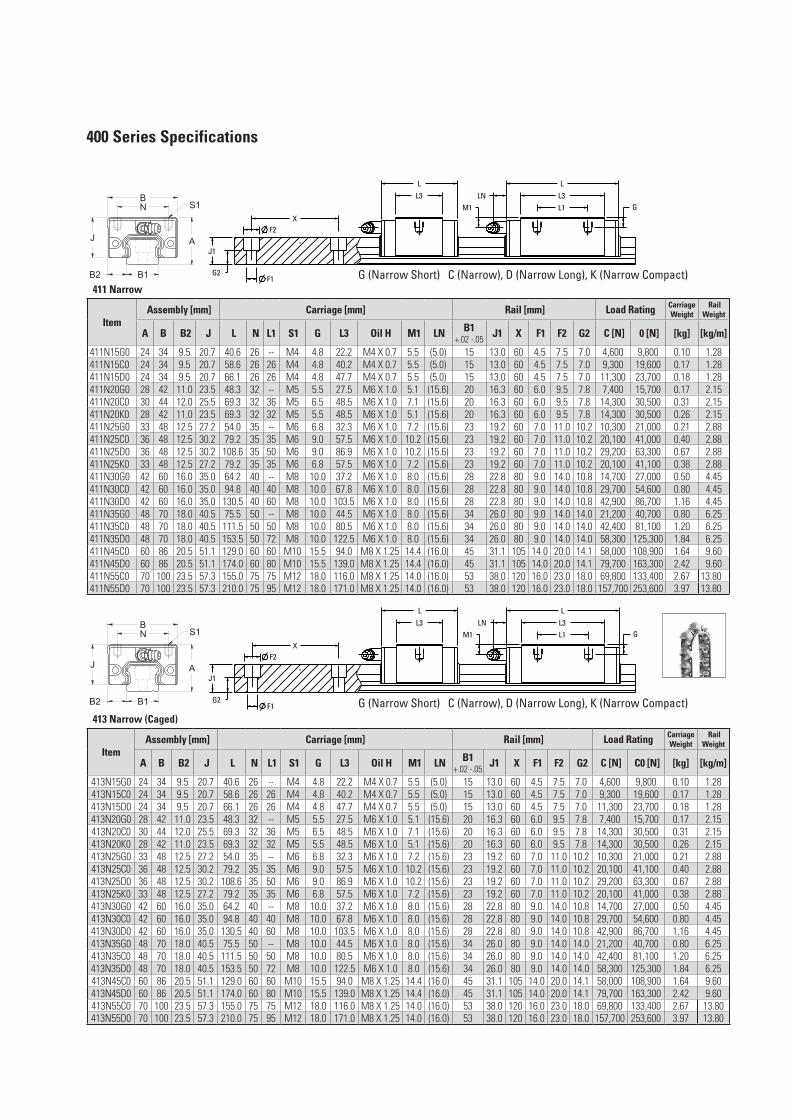
400 Series Specifications
411 Narrow
Item Assembly [mm] Carriage [mm] Rail [mm] Load Rating Carriage
Weight Rail
Weight
A B B2 J L N L1 S1 G L3 Oil H M1 LN B1+.02 -.05 J1 X F1 F2 G2 C [N] 0 [N] [kg] [kg/m]
411N15G0 24 34 9.5 20.7 40.6 26 -- M4 4.8 22.2 M4 X 0.7 5.5 (5.0) 15 13.0 60 4.5 7.5 7.0 4,600 9,800 0.10 1.28411N15C0 24 34 9.5 20.7 58.6 26 26 M4 4.8 40.2 M4 X 0.7 5.5 (5.0) 15 13.0 60 4.5 7.5 7.0 9,300 19,600 0.17 1.28411N15D0 24 34 9.5 20.7 66.1 26 26 M4 4.8 47.7 M4 X 0.7 5.5 (5.0) 15 13.0 60 4.5 7.5 7.0 11,300 23,700 0.18 1.28411N20G0 28 42 11.0 23.5 48.3 32 -- M5 5.5 27.5 M6 X 1.0 5.1 (15.6) 20 16.3 60 6.0 9.5 7.8 7,400 15,700 0.17 2.15411N20C0 30 44 12.0 25.5 69.3 32 36 M5 6.5 48.5 M6 X 1.0 7.1 (15.6) 20 16.3 60 6.0 9.5 7.8 14,300 30,500 0.31 2.15411N20K0 28 42 11.0 23.5 69.3 32 32 M5 5.5 48.5 M6 X 1.0 5.1 (15.6) 20 16.3 60 6.0 9.5 7.8 14,300 30,500 0.26 2.15411N25G0 33 48 12.5 27.2 54.0 35 -- M6 6.8 32.3 M6 X 1.0 7.2 (15.6) 23 19.2 60 7.0 11.0 10.2 10,300 21,000 0.21 2.88411N25C0 36 48 12.5 30.2 79.2 35 35 M6 9.0 57.5 M6 X 1.0 10.2 (15.6) 23 19.2 60 7.0 11.0 10.2 20,100 41,000 0.40 2.88411N25D0 36 48 12.5 30.2 108.6 35 50 M6 9.0 86.9 M6 X 1.0 10.2 (15.6) 23 19.2 60 7.0 11.0 10.2 29,200 63,300 0.67 2.88411N25K0 33 48 12.5 27.2 79.2 35 35 M6 6.8 57.5 M6 X 1.0 7.2 (15.6) 23 19.2 60 7.0 11.0 10.2 20,100 41,100 0.38 2.88411N30G0 42 60 16.0 35.0 64.2 40 -- M8 10.0 37.2 M6 X 1.0 8.0 (15.6) 28 22.8 80 9.0 14.0 10.8 14,700 27,000 0.50 4.45411N30C0 42 60 16.0 35.0 94.8 40 40 M8 10.0 67.8 M6 X 1.0 8.0 (15.6) 28 22.8 80 9.0 14.0 10.8 29,700 54,600 0.80 4.45411N30D0 42 60 16.0 35.0 130.5 40 60 M8 10.0 103.5 M6 X 1.0 8.0 (15.6) 28 22.8 80 9.0 14.0 10.8 42,900 86,700 1.16 4.45411N35G0 48 70 18.0 40.5 75.5 50 -- M8 10.0 44.5 M6 X 1.0 8.0 (15.6) 34 26.0 80 9.0 14.0 14.0 21,200 40,700 0.80 6.25411N35C0 48 70 18.0 40.5 111.5 50 50 M8 10.0 80.5 M6 X 1.0 8.0 (15.6) 34 26.0 80 9.0 14.0 14.0 42,400 81,100 1.20 6.25411N35D0 48 70 18.0 40.5 153.5 50 72 M8 10.0 122.5 M6 X 1.0 8.0 (15.6) 34 26.0 80 9.0 14.0 14.0 58,300 125,300 1.84 6.25411N45C0 60 86 20.5 51.1 129.0 60 60 M10 15.5 94.0 M8 X 1.25 14.4 (16.0) 45 31.1 105 14.0 20.0 14.1 58,000 108,900 1.64 9.60411N45D0 60 86 20.5 51.1 174.0 60 80 M10 15.5 139.0 M8 X 1.25 14.4 (16.0) 45 31.1 105 14.0 20.0 14.1 79,700 163,300 2.42 9.60411N55C0 70 100 23.5 57.3 155.0 75 75 M12 18.0 116.0 M8 X 1.25 14.0 (16.0) 53 38.0 120 16.0 23.0 18.0 69,800 133,400 2.67 13.80411N55D0 70 100 23.5 57.3 210.0 75 95 M12 18.0 171.0 M8 X 1.25 14.0 (16.0) 53 38.0 120 16.0 23.0 18.0 157,700 253,600 3.97 13.80
413 Narrow (Caged)
Item Assembly [mm] Carriage [mm] Rail [mm] Load Rating Carriage
Weight Rail
Weight
A B B2 J L N L1 S1 G L3 Oil H M1 LN B1+.02 -.05 J1 X F1 F2 G2 C [N] C0 [N] [kg] [kg/m]
413N15G0 24 34 9.5 20.7 40.6 26 -- M4 4.8 22.2 M4 X 0.7 5.5 (5.0) 15 13.0 60 4.5 7.5 7.0 4,600 9,800 0.10 1.28413N15C0 24 34 9.5 20.7 58.6 26 26 M4 4.8 40.2 M4 X 0.7 5.5 (5.0) 15 13.0 60 4.5 7.5 7.0 9,300 19,600 0.17 1.28413N15D0 24 34 9.5 20.7 66.1 26 26 M4 4.8 47.7 M4 X 0.7 5.5 (5.0) 15 13.0 60 4.5 7.5 7.0 11,300 23,700 0.18 1.28413N20G0 28 42 11.0 23.5 48.3 32 -- M5 5.5 27.5 M6 X 1.0 5.1 (15.6) 20 16.3 60 6.0 9.5 7.8 7,400 15,700 0.17 2.15413N20C0 30 44 12.0 25.5 69.3 32 36 M5 6.5 48.5 M6 X 1.0 7.1 (15.6) 20 16.3 60 6.0 9.5 7.8 14,300 30,500 0.31 2.15413N20K0 28 42 11.0 23.5 69.3 32 32 M5 5.5 48.5 M6 X 1.0 5.1 (15.6) 20 16.3 60 6.0 9.5 7.8 14,300 30,500 0.26 2.15413N25G0 33 48 12.5 27.2 54.0 35 -- M6 6.8 32.3 M6 X 1.0 7.2 (15.6) 23 19.2 60 7.0 11.0 10.2 10,300 21,000 0.21 2.88413N25C0 36 48 12.5 30.2 79.2 35 35 M6 9.0 57.5 M6 X 1.0 10.2 (15.6) 23 19.2 60 7.0 11.0 10.2 20,100 41,100 0.40 2.88413N25D0 36 48 12.5 30.2 108.6 35 50 M6 9.0 86.9 M6 X 1.0 10.2 (15.6) 23 19.2 60 7.0 11.0 10.2 29,200 63,300 0.67 2.88413N25K0 33 48 12.5 27.2 79.2 35 35 M6 6.8 57.5 M6 X 1.0 7.2 (15.6) 23 19.2 60 7.0 11.0 10.2 20,100 41,000 0.38 2.88413N30G0 42 60 16.0 35.0 64.2 40 -- M8 10.0 37.2 M6 X 1.0 8.0 (15.6) 28 22.8 80 9.0 14.0 10.8 14,700 27,000 0.50 4.45413N30C0 42 60 16.0 35.0 94.8 40 40 M8 10.0 67.8 M6 X 1.0 8.0 (15.6) 28 22.8 80 9.0 14.0 10.8 29,700 54,600 0.80 4.45413N30D0 42 60 16.0 35.0 130.5 40 60 M8 10.0 103.5 M6 X 1.0 8.0 (15.6) 28 22.8 80 9.0 14.0 10.8 42,900 86,700 1.16 4.45413N35G0 48 70 18.0 40.5 75.5 50 -- M8 10.0 44.5 M6 X 1.0 8.0 (15.6) 34 26.0 80 9.0 14.0 14.0 21,200 40,700 0.80 6.25413N35C0 48 70 18.0 40.5 111.5 50 50 M8 10.0 80.5 M6 X 1.0 8.0 (15.6) 34 26.0 80 9.0 14.0 14.0 42,400 81,100 1.20 6.25413N35D0 48 70 18.0 40.5 153.5 50 72 M8 10.0 122.5 M6 X 1.0 8.0 (15.6) 34 26.0 80 9.0 14.0 14.0 58,300 125,300 1.84 6.25413N45C0 60 86 20.5 51.1 129.0 60 60 M10 15.5 94.0 M8 X 1.25 14.4 (16.0) 45 31.1 105 14.0 20.0 14.1 58,000 108,900 1.64 9.60413N45D0 60 86 20.5 51.1 174.0 60 80 M10 15.5 139.0 M8 X 1.25 14.4 (16.0) 45 31.1 105 14.0 20.0 14.1 79,700 163,300 2.42 9.60413N55C0 70 100 23.5 57.3 155.0 75 75 M12 18.0 116.0 M8 X 1.25 14.0 (16.0) 53 38.0 120 16.0 23.0 18.0 69,800 133,400 2.67 13.80413N55D0 70 100 23.5 57.3 210.0 75 95 M12 18.0 171.0 M8 X 1.25 14.0 (16.0) 53 38.0 120 16.0 23.0 18.0 157,700 253,600 3.97 13.80
G (Narrow Short) C (Narrow), D (Narrow Long), K (Narrow Compact)
G (Narrow Short) C (Narrow), D (Narrow Long), K (Narrow Compact)
J A
NB
B2
J1
G2F1
F2X
M1 L1
L3
L L
L3
B1
LNG S1
J A
NB
B2
J1
G2F1
F2X
M1 L1
L3
L L
L3
B1
LNG S1
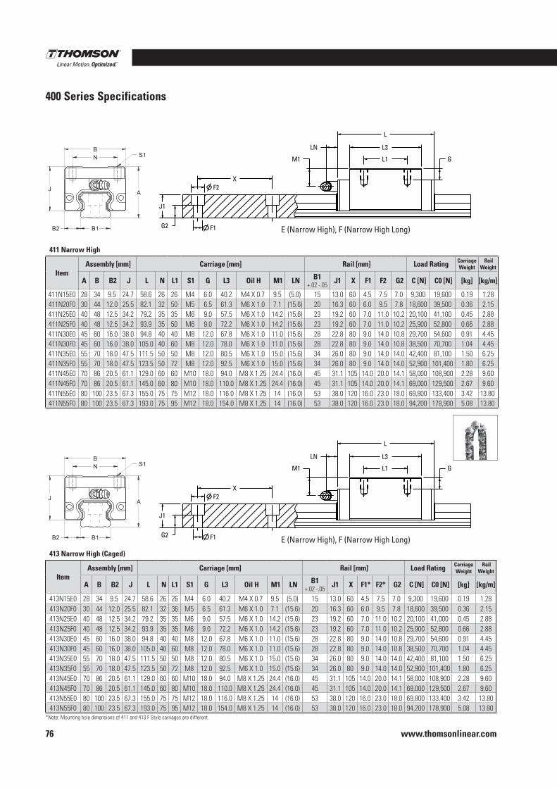
www.thomsonlinear.com76
400 Series Specifications
413 Narrow High (Caged)
Item Assembly [mm] Carriage [mm] Rail [mm] Load Rating Carriage
Weight Rail
Weight
A B B2 J L N L1 S1 G L3 Oil H M1 LN B1+.02 -.05 J1 X F1* F2* G2 C [N] C0 [N] [kg] [kg/m]
413N15E0 28 34 9.5 24.7 58.6 26 26 M4 6.0 40.2 M4 X 0.7 9.5 (5.0) 15 13.0 60 4.5 7.5 7.0 9,300 19,600 0.19 1.28413N20F0 30 44 12.0 25.5 82.1 32 36 M5 6.5 61.3 M6 X 1.0 7.1 (15.6) 20 16.3 60 6.0 9.5 7.8 18,600 39,500 0.36 2.15413N25E0 40 48 12.5 34.2 79.2 35 35 M6 9.0 57.5 M6 X 1.0 14.2 (15.6) 23 19.2 60 7.0 11.0 10.2 20,100 41,000 0.45 2.88413N25F0 40 48 12.5 34.2 93.9 35 35 M6 9.0 72.2 M6 X 1.0 14.2 (15.6) 23 19.2 60 7.0 11.0 10.2 25,900 52,800 0.66 2.88413N30E0 45 60 16.0 38.0 94.8 40 40 M8 12.0 67.8 M6 X 1.0 11.0 (15.6) 28 22.8 80 9.0 14.0 10.8 29,700 54,600 0.91 4.45413N30F0 45 60 16.0 38.0 105.0 40 60 M8 12.0 78.0 M6 X 1.0 11.0 (15.6) 28 22.8 80 9.0 14.0 10.8 38,500 70,700 1.04 4.45413N35E0 55 70 18.0 47.5 111.5 50 50 M8 12.0 80.5 M6 X 1.0 15.0 (15.6) 34 26.0 80 9.0 14.0 14.0 42,400 81,100 1.50 6.25413N35F0 55 70 18.0 47.5 123.5 50 72 M8 12.0 92.5 M6 X 1.0 15.0 (15.6) 34 26.0 80 9.0 14.0 14.0 52,900 101,400 1.80 6.25413N45E0 70 86 20.5 61.1 129.0 60 60 M10 18.0 94.0 M8 X 1.25 24.4 (16.0) 45 31.1 105 14.0 20.0 14.1 58,000 108,900 2.28 9.60413N45F0 70 86 20.5 61.1 145.0 60 80 M10 18.0 110.0 M8 X 1.25 24.4 (16.0) 45 31.1 105 14.0 20.0 14.1 69,000 129,500 2.67 9.60413N55E0 80 100 23.5 67.3 155.0 75 75 M12 18.0 116.0 M8 X 1.25 14 (16.0) 53 38.0 120 16.0 23.0 18.0 69,800 133,400 3.42 13.80413N55F0 80 100 23.5 67.3 193.0 75 95 M12 18.0 154.0 M8 X 1.25 14 (16.0) 53 38.0 120 16.0 23.0 18.0 94,200 178,900 5.08 13.80
411 Narrow High
Item Assembly [mm] Carriage [mm] Rail [mm] Load Rating Carriage
Weight Rail
Weight
A B B2 J L N L1 S1 G L3 Oil H M1 LN B1+.02 -.05 J1 X F1 F2 G2 C [N] C0 [N] [kg] [kg/m]
411N15E0 28 34 9.5 24.7 58.6 26 26 M4 6.0 40.2 M4 X 0.7 9.5 (5.0) 15 13.0 60 4.5 7.5 7.0 9,300 19,600 0.19 1.28411N20F0 30 44 12.0 25.5 82.1 32 50 M5 6.5 61.3 M6 X 1.0 7.1 (15.6) 20 16.3 60 6.0 9.5 7.8 18,600 39,500 0.36 2.15411N25E0 40 48 12.5 34.2 79.2 35 35 M6 9.0 57.5 M6 X 1.0 14.2 (15.6) 23 19.2 60 7.0 11.0 10.2 20,100 41,100 0.45 2.88411N25F0 40 48 12.5 34.2 93.9 35 50 M6 9.0 72.2 M6 X 1.0 14.2 (15.6) 23 19.2 60 7.0 11.0 10.2 25,900 52,800 0.66 2.88411N30E0 45 60 16.0 38.0 94.8 40 40 M8 12.0 67.8 M6 X 1.0 11.0 (15.6) 28 22.8 80 9.0 14.0 10.8 29,700 54,600 0.91 4.45411N30F0 45 60 16.0 38.0 105.0 40 60 M8 12.0 78.0 M6 X 1.0 11.0 (15.6) 28 22.8 80 9.0 14.0 10.8 38,500 70,700 1.04 4.45411N35E0 55 70 18.0 47.5 111.5 50 50 M8 12.0 80.5 M6 X 1.0 15.0 (15.6) 34 26.0 80 9.0 14.0 14.0 42,400 81,100 1.50 6.25411N35F0 55 70 18.0 47.5 123.5 50 72 M8 12.0 92.5 M6 X 1.0 15.0 (15.6) 34 26.0 80 9.0 14.0 14.0 52,900 101,400 1.80 6.25411N45E0 70 86 20.5 61.1 129.0 60 60 M10 18.0 94.0 M8 X 1.25 24.4 (16.0) 45 31.1 105 14.0 20.0 14.1 58,000 108,900 2.28 9.60411N45F0 70 86 20.5 61.1 145.0 60 80 M10 18.0 110.0 M8 X 1.25 24.4 (16.0) 45 31.1 105 14.0 20.0 14.1 69,000 129,500 2.67 9.60411N55E0 80 100 23.5 67.3 155.0 75 75 M12 18.0 116.0 M8 X 1.25 14 (16.0) 53 38.0 120 16.0 23.0 18.0 69,800 133,400 3.42 13.80411N55F0 80 100 23.5 67.3 193.0 75 95 M12 18.0 154.0 M8 X 1.25 14 (16.0) 53 38.0 120 16.0 23.0 18.0 94,200 178,900 5.08 13.80
E (Narrow High), F (Narrow High Long)
E (Narrow High), F (Narrow High Long)
*Note: Mounting hole dimensions of 411 and 413 F Style carriages are different.
XF2
F1
A
N
B2
J
B
L1
L3
L
M1
J1
G2B1
LN
G S1
XF2
F1
A
N
B2
J
B
L1
L3
L
M1
J1
G2B1
LN
G S1
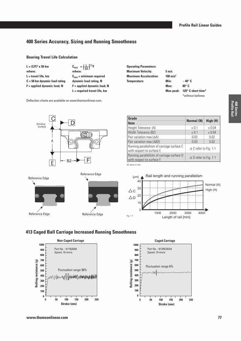
Profile Rail Linear Guides
www.thomsonlinear.com 77
400 Series Profile Rail
400 Series Accuracy, Sizing and Running Smoothness
GradeNormal (N) High (H)
ItemHeight Tolerance (A) ± 0.1 ± 0.04Width Tolerance (B2) ± 0.1 ± 0.04Pair variation max (∆A) 0.03 0.02Pair variation max (∆B2) 0.03 0.02Running parallellism of carriage surface C with respect to surface E. ∆ C refer to Fig. 1-1
Running parallellsim of carriage surface D with respect to surface F. ∆ D refer to Fig. 1-1
All items in mm.
Fig. 1-1
413 Caged Ball Carriage Increased Running Smoothness
Fluctuation range 38%
Rolli
ng re
sist
ance
(g)
Stroke (mm)
Part No. : 411N25A0Speed: 10 mm/s
1000
900
800
700
600
500
400
300
200
100
00 50 100 150 200 250
Non-Caged Carriage
Fluctuation range 6%
Rolli
ng re
sist
ance
(g)
Stroke (mm)
Part No. : 413N25A 0Speed: 10 mm/s
1000
900
800
700
600
500
400
300
200
100
00 50 100 150 200 250
Caged Carriage
L = (C/F)3 x 50 kmwhere:L = travel life, kmC = 50 km dynamic load ratingF = applied dynamic load, N
Cmin = F where:Cmin = minimum required dynamic load rating, NF = applied dynamic load, NL = required travel life, km
Operating Parameters:Maximum Velocity: 5 m/s Maximum Acceleration: 100 m/s2 Temperature: Min: – 40° C Max: 80° C Max peak: 120° C short time* *without bellows
Bearing Travel Life Calculation
( ) L 50
1⁄3
Reference Edge
Reference Edge
Reference Edge
Reference Edge
Deflection charts are available on www .thomsonlinear .com .
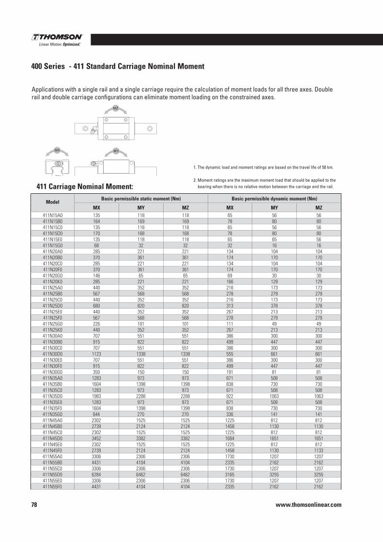
www.thomsonlinear.com78
411 Carriage Nominal Moment:
ModelBasic permissible static moment (Nm) Basic permissible dynamic moment (Nm)
MX MY MZ MX MY MZ411N15A0 135 118 118 65 56 56411N15B0 164 169 169 78 80 80411N15C0 135 118 118 65 56 56411N15D0 170 168 168 78 80 80411N15E0 135 118 118 65 65 56411N15G0 68 32 32 32 16 16411N20A0 285 221 221 134 104 104411N20B0 370 361 361 174 170 170411N20C0 285 221 221 134 104 104411N20F0 370 361 361 174 170 170411N20G0 146 65 65 69 30 30411N20K0 285 221 221 166 129 129411N25A0 440 352 352 216 173 173411N25B0 567 568 568 278 279 279411N25C0 440 352 352 216 173 173411N25D0 680 820 820 313 378 378411N25E0 440 352 352 267 213 213411N25F0 567 568 568 278 279 279411N25G0 226 101 101 111 49 49411N25K0 440 352 352 267 213 213411N30A0 707 551 551 386 300 300411N30B0 915 822 822 499 447 447411N30C0 707 551 551 386 300 300411N30D0 1123 1338 1338 555 661 661411N30E0 707 551 551 386 300 300411N30F0 915 822 822 499 447 447411N30G0 350 150 150 191 81 81411N35A0 1283 973 973 671 508 508411N35B0 1604 1398 1398 838 730 730411N35C0 1283 973 973 671 508 508411N35D0 1983 2288 2288 922 1063 1063411N35E0 1283 973 973 671 508 508411N35F0 1604 1398 1398 838 730 730411N35G0 644 270 270 336 141 141411N45A0 2302 1525 1525 1225 812 812411N45B0 2739 2124 2124 1458 1130 1130411N45C0 2302 1525 1525 1225 812 812411N45D0 3452 3382 3382 1684 1651 1651411N45E0 2302 1525 1525 1225 812 812411N45F0 2739 2124 2124 1458 1130 1133411N55A0 3306 2306 2306 1730 1207 1207411N55B0 4431 4104 4104 2335 2162 2162411N55C0 3306 2306 2306 1730 1207 1207411N55D0 6284 6462 6462 3165 3255 3255411N55E0 3306 2306 2306 1730 1207 1207411N55F0 4431 4104 4104 2335 2162 2162
MX MY
MZ
Applications with a single rail and a single carriage require the calculation of moment loads for all three axes . Double rail and double carriage configurations can eliminate moment loading on the constrained axes .
400 Series - 411 Standard Carriage Nominal Moment
1 . The dynamic load and moment ratings are based on the travel life of 50 km .
2 . Moment ratings are the maximum moment load that should be applied to the bearing when there is no relative motion between the carriage and the rail .
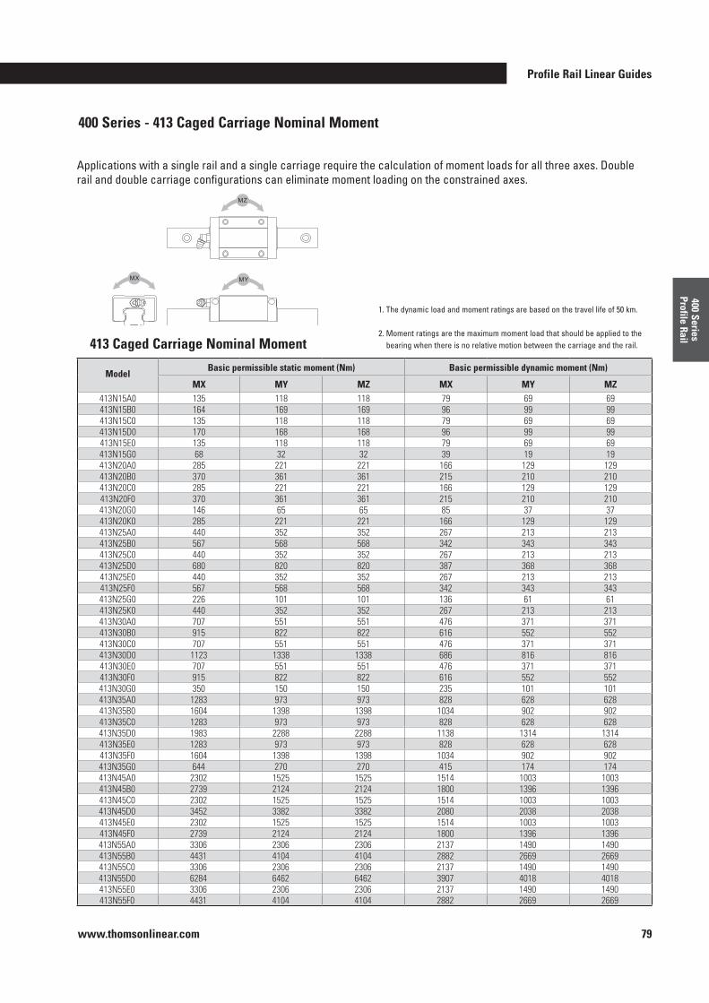
Profile Rail Linear Guides
www.thomsonlinear.com 79
400 Series Profile Rail
ModelBasic permissible static moment (Nm) Basic permissible dynamic moment (Nm)
MX MY MZ MX MY MZ413N15A0 135 118 118 79 69 69413N15B0 164 169 169 96 99 99413N15C0 135 118 118 79 69 69413N15D0 170 168 168 96 99 99413N15E0 135 118 118 79 69 69413N15G0 68 32 32 39 19 19413N20A0 285 221 221 166 129 129413N20B0 370 361 361 215 210 210413N20C0 285 221 221 166 129 129413N20F0 370 361 361 215 210 210413N20G0 146 65 65 85 37 37413N20K0 285 221 221 166 129 129413N25A0 440 352 352 267 213 213413N25B0 567 568 568 342 343 343413N25C0 440 352 352 267 213 213413N25D0 680 820 820 387 368 368413N25E0 440 352 352 267 213 213413N25F0 567 568 568 342 343 343413N25G0 226 101 101 136 61 61413N25K0 440 352 352 267 213 213413N30A0 707 551 551 476 371 371413N30B0 915 822 822 616 552 552413N30C0 707 551 551 476 371 371413N30D0 1123 1338 1338 686 816 816413N30E0 707 551 551 476 371 371413N30F0 915 822 822 616 552 552413N30G0 350 150 150 235 101 101413N35A0 1283 973 973 828 628 628413N35B0 1604 1398 1398 1034 902 902413N35C0 1283 973 973 828 628 628413N35D0 1983 2288 2288 1138 1314 1314413N35E0 1283 973 973 828 628 628413N35F0 1604 1398 1398 1034 902 902413N35G0 644 270 270 415 174 174413N45A0 2302 1525 1525 1514 1003 1003413N45B0 2739 2124 2124 1800 1396 1396413N45C0 2302 1525 1525 1514 1003 1003413N45D0 3452 3382 3382 2080 2038 2038413N45E0 2302 1525 1525 1514 1003 1003413N45F0 2739 2124 2124 1800 1396 1396413N55A0 3306 2306 2306 2137 1490 1490413N55B0 4431 4104 4104 2882 2669 2669413N55C0 3306 2306 2306 2137 1490 1490413N55D0 6284 6462 6462 3907 4018 4018413N55E0 3306 2306 2306 2137 1490 1490413N55F0 4431 4104 4104 2882 2669 2669
MX MY
MZ
Applications with a single rail and a single carriage require the calculation of moment loads for all three axes . Double rail and double carriage configurations can eliminate moment loading on the constrained axes .
400 Series - 413 Caged Carriage Nominal Moment
413 Caged Carriage Nominal Moment
1 . The dynamic load and moment ratings are based on the travel life of 50 km .
2 . Moment ratings are the maximum moment load that should be applied to the bearing when there is no relative motion between the carriage and the rail .
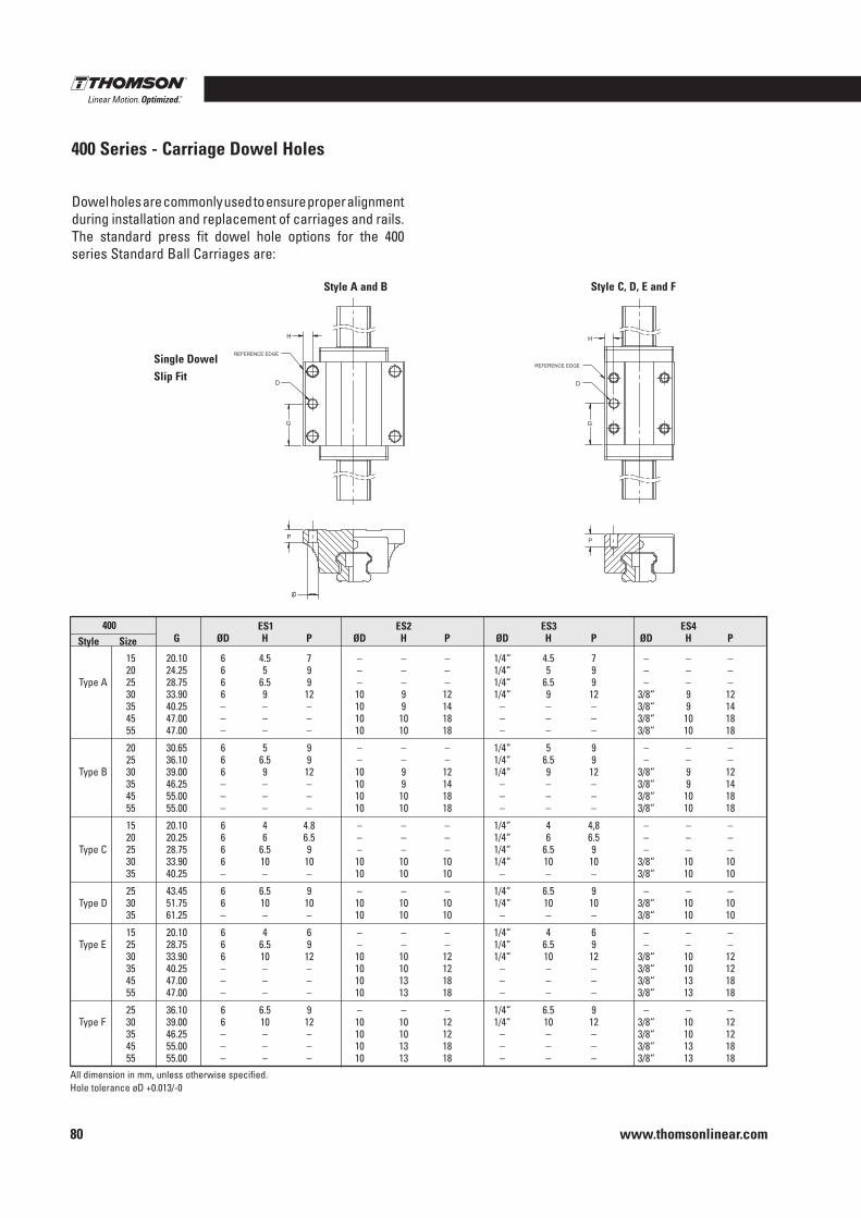
www.thomsonlinear.com80
Dowel holes are commonly used to ensure proper alignment during installation and replacement of carriages and rails . The standard press fit dowel hole options for the 400 series Standard Ball Carriages are:
Style A and B Style C, D, E and F
Single DowelSlip Fit
ES1 ES2 ES3 ES4 G ØD H P ØD H P ØD H P ØD H P
15 20 .10 6 4 .5 7 – – – 1/4“ 4 .5 7 – – – 20 24 .25 6 5 9 – – – 1/4“ 5 9 – – – Type A 25 28 .75 6 6 .5 9 – – – 1/4“ 6 .5 9 – – – 30 33 .90 6 9 12 10 9 12 1/4“ 9 12 3/8“ 9 12 35 40 .25 – – – 10 9 14 – – – 3/8“ 9 14 45 47 .00 – – – 10 10 18 – – – 3/8“ 10 18 55 47 .00 – – – 10 10 18 – – – 3/8“ 10 18
20 30 .65 6 5 9 – – – 1/4“ 5 9 – – – 25 36 .10 6 6 .5 9 – – – 1/4“ 6 .5 9 – – – Type B 30 39 .00 6 9 12 10 9 12 1/4“ 9 12 3/8“ 9 12 35 46 .25 – – – 10 9 14 – – – 3/8“ 9 14 45 55 .00 – – – 10 10 18 – – – 3/8“ 10 18 55 55 .00 – – – 10 10 18 – – – 3/8“ 10 18
15 20 .10 6 4 4 .8 – – – 1/4“ 4 4,8 – – – 20 20 .25 6 6 6 .5 – – – 1/4“ 6 6 .5 – – – Type C 25 28 .75 6 6 .5 9 – – – 1/4“ 6 .5 9 – – – 30 33 .90 6 10 10 10 10 10 1/4“ 10 10 3/8“ 10 10 35 40 .25 – – – 10 10 10 – – – 3/8“ 10 10
25 43 .45 6 6 .5 9 – – – 1/4“ 6 .5 9 – – – Type D 30 51 .75 6 10 10 10 10 10 1/4“ 10 10 3/8“ 10 10 35 61 .25 – – – 10 10 10 – – – 3/8“ 10 10
15 20 .10 6 4 6 – – – 1/4“ 4 6 – – – Type E 25 28 .75 6 6 .5 9 – – – 1/4“ 6 .5 9 – – – 30 33 .90 6 10 12 10 10 12 1/4“ 10 12 3/8“ 10 12 35 40 .25 – – – 10 10 12 – – – 3/8“ 10 12 45 47 .00 – – – 10 13 18 – – – 3/8“ 13 18 55 47 .00 – – – 10 13 18 – – – 3/8“ 13 18
25 36 .10 6 6 .5 9 – – – 1/4“ 6 .5 9 – – – Type F 30 39 .00 6 10 12 10 10 12 1/4“ 10 12 3/8“ 10 12 35 46 .25 – – – 10 10 12 – – – 3/8“ 10 12 45 55 .00 – – – 10 13 18 – – – 3/8“ 13 18 55 55 .00 – – – 10 13 18 – – – 3/8“ 13 18
400Style Size
400 Series - Carriage Dowel Holes
REFERENCE EDGE
D D
REFERENCE EDGE
All dimension in mm, unless otherwise specified .Hole tolerance øD +0 .013/-0
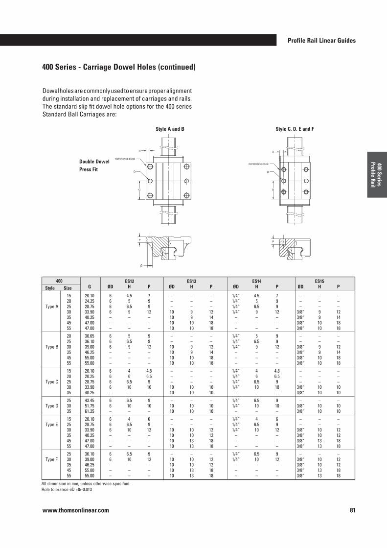
Profile Rail Linear Guides
www.thomsonlinear.com 81
400 Series Profile Rail
Dowel holes are commonly used to ensure proper alignment during installation and replacement of carriages and rails . The standard slip fit dowel hole options for the 400 series Standard Ball Carriages are:
Style A and B Style C, D, E and F
Double DowelPress Fit
ES12 ES13 ES14 ES15 G ØD H P ØD H P ØD H P ØD H P
15 20 .10 6 4 .5 7 – – – 1/4“ 4 .5 7 – – – 20 24 .25 6 5 9 – – – 1/4“ 5 9 – – – Type A 25 28 .75 6 6 .5 9 – – – 1/4“ 6 .5 9 – – – 30 33 .90 6 9 12 10 9 12 1/4“ 9 12 3/8“ 9 12 35 40 .25 – – – 10 9 14 – – – 3/8“ 9 14 45 47 .00 – – – 10 10 18 – – – 3/8“ 10 18 55 47 .00 – – – 10 10 18 – – – 3/8“ 10 18
20 30 .65 6 5 9 – – – 1/4“ 5 9 – – – 25 36 .10 6 6 .5 9 – – – 1/4“ 6 .5 9 – – – Type B 30 39 .00 6 9 12 10 9 12 1/4“ 9 12 3/8“ 9 12 35 46 .25 – – – 10 9 14 – – – 3/8“ 9 14 45 55 .00 – – – 10 10 18 – – – 3/8“ 10 18 55 55 .00 – – – 10 10 18 – – – 3/8“ 10 18
15 20 .10 6 4 4 .8 – – – 1/4“ 4 4,8 – – – 20 20 .25 6 6 6 .5 – – – 1/4“ 6 6 .5 – – – Type C 25 28 .75 6 6 .5 9 – – – 1/4“ 6 .5 9 – – – 30 33 .90 6 10 10 10 10 10 1/4“ 10 10 3/8“ 10 10 35 40 .25 – – – 10 10 10 – – – 3/8“ 10 10
25 43 .45 6 6 .5 9 – – – 1/4“ 6 .5 9 – – – Type D 30 51 .75 6 10 10 10 10 10 1/4“ 10 10 3/8“ 10 10 35 61 .25 – – – 10 10 10 – – – 3/8“ 10 10
15 20 .10 6 4 6 – – – 1/4“ 4 6 – – – Type E 25 28 .75 6 6 .5 9 – – – 1/4“ 6 .5 9 – – – 30 33 .90 6 10 12 10 10 12 1/4“ 10 12 3/8“ 10 12 35 40 .25 – – – 10 10 12 – – – 3/8“ 10 12 45 47 .00 – – – 10 13 18 – – – 3/8“ 13 18 55 47 .00 – – – 10 13 18 – – – 3/8“ 13 18
25 36 .10 6 6 .5 9 – – – 1/4“ 6 .5 9 – – – Type F 30 39 .00 6 10 12 10 10 12 1/4“ 10 12 3/8“ 10 12 35 46 .25 – – – 10 10 12 – – – 3/8“ 10 12 45 55 .00 – – – 10 13 18 – – – 3/8“ 13 18 55 55 .00 – – – 10 13 18 – – – 3/8“ 13 18
400Style Size
400 Series - Carriage Dowel Holes (continued)
REFERENCE EDGE
D D
REFERENCE EDGE
All dimension in mm, unless otherwise specified .Hole tolerance øD +0/-0 .013
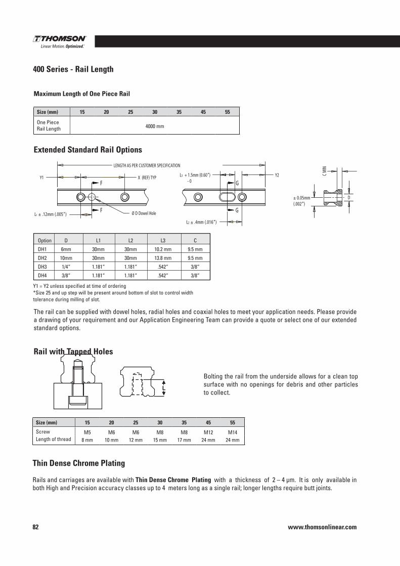
www.thomsonlinear.com82
L3 + 1.5mm (0.60”) - 0
Ø D Dowel Hole
LENGTH AS PER CUSTOMER SPECIFICATION
Y1 X (REF) TYP
L1 ± .12mm (.005”)
Y2
L2 ± .4mm (.016”)
D
C M
IN
F
F
G
G
± 0.05mm (.002”)
Y1 = Y2 unless specified at time of ordering*Size 25 and up step will be present around bottom of slot to control width tolerance during milling of slot .
The rail can be supplied with dowel holes, radial holes and coaxial holes to meet your application needs . Please provide a drawing of your requirement and our Application Engineering Team can provide a quote or select one of our extended standard options .
Thin Dense Chrome Plating Rails and carriages are available with Thin Dense Chrome Plating with a thickness of 2 – 4 µm . It is only available in both High and Precision accuracy classes up to 4 meters long as a single rail; longer lengths require butt joints .
Bolting the rail from the underside allows for a clean top surface with no openings for debris and other particles to collect .
Maximum Length of One Piece Rail
400 Series - Rail Length
Rail with Tapped Holes
Extended Standard Rail Options
Option D L1 L2 L3 C
DH1 6mm 30mm 30mm 10 .2 mm 9 .5 mm
DH2 10mm 30mm 30mm 13 .8 mm 9 .5 mm
DH3 1/4“ 1 .181“ 1 .181“ .542“ 3/8“
DH4 3/8“ 1 .181“ 1 .181“ .542“ 3/8“
Size (mm) 15 20 25 30 35 45 55
One Piece Rail Length 4000 mm
Size (mm) 15 20 25 30 35 45 55
Screw M5 M6 M6 M8 M8 M12 M14Length of thread 8 mm 10 mm 12 mm 15 mm 17 mm 24 mm 24 mm
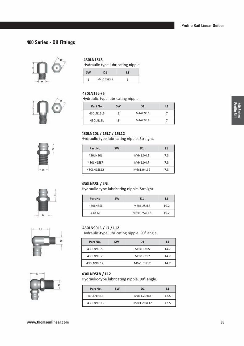
Profile Rail Linear Guides
www.thomsonlinear.com 83
400 Series Profile Rail
400 Series - Oil Fittings
°
°
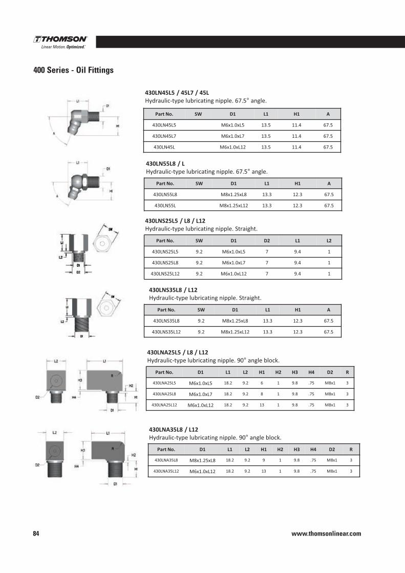
www.thomsonlinear.com84
400 Series - Oil Fittings
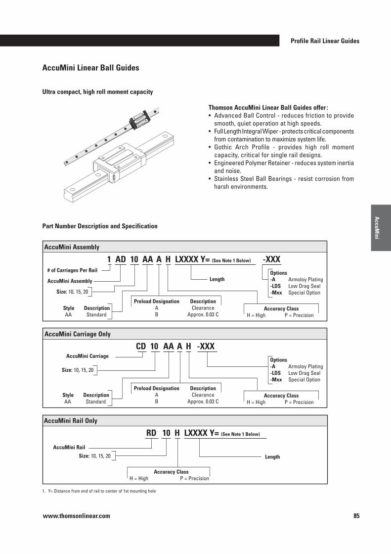
Profile Rail Linear Guides
www.thomsonlinear.com 85
AccuM
ini
AccuMini Linear Ball Guides
Ultra compact, high roll moment capacity
1 . Y= Distance from end of rail to center of 1st mounting hole
Thomson AccuMini Linear Ball Guides offer :• Advanced Ball Control - reduces friction to provide
smooth, quiet operation at high speeds .• Full Length Integral Wiper - protects critical components
from contamination to maximize system life .• Gothic Arch Profile - provides high roll moment
capacity, critical for single rail designs .• Engineered Polymer Retainer - reduces system inertia
and noise .• Stainless Steel Ball Bearings - resist corrosion from
harsh environments .
Part Number Description and Specification
1 AD 10 AA A H LXXXX Y= (See Note 1 Below) -XXX AccuMini Assembly
Size: 10, 15, 20
# of Carriages Per Rail
LengthAccuMini AssemblyOptions -A Armoloy Plating-LDS Low Drag Seal-Mxx Special Option
Style DescriptionAA Standard
Accuracy ClassH = High P = Precision
Preload Designation Description A Clearance B Approx . 0 .03 C
CD 10 AA A H -XXX AccuMini Carriage Only
Size: 10, 15, 20
AccuMini CarriageOptions -A Armoloy Plating-LDS Low Drag Seal-Mxx Special Option
Style DescriptionAA Standard
Accuracy ClassH = High P = Precision
Preload Designation Description A Clearance B Approx . 0 .03 C
RD 10 H LXXXX Y= (See Note 1 Below)
AccuMini Rail Only
Size: 10, 15, 20 Length
Accuracy ClassH = High P = Precision
AccuMini Rail
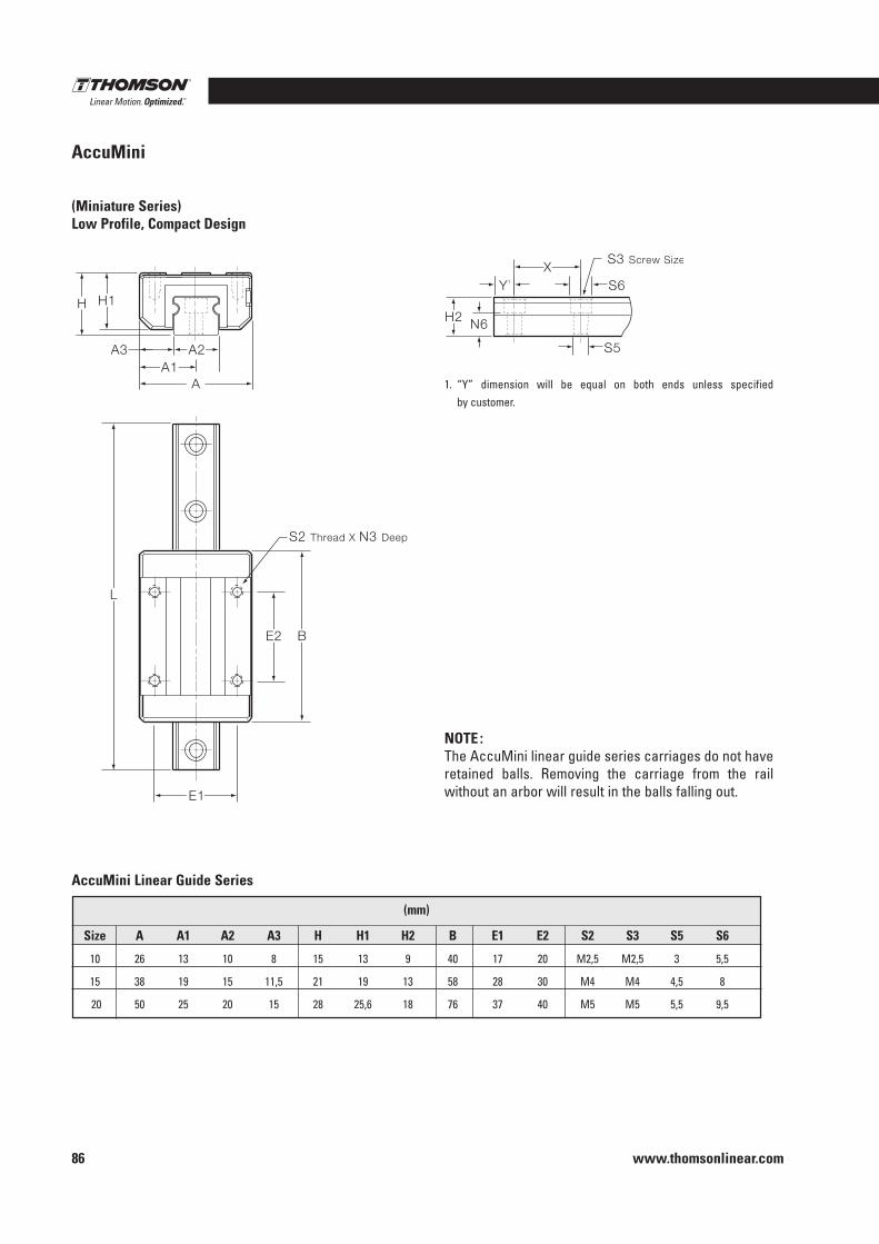
www.thomsonlinear.com86
AccuMini
1
AccuMini Linear Guide Series
NOTE :The AccuMini linear guide series carriages do not have retained balls . Removing the carriage from the rail without an arbor will result in the balls falling out .
(mm)
Size A A1 A2 A3 H H1 H2 B E1 E2 S2 S3 S5 S6
10 26 13 10 8 15 13 9 40 17 20 M2,5 M2,5 3 5,5
15 38 19 15 11,5 21 19 13 58 28 30 M4 M4 4,5 8
20 50 25 20 15 28 25,6 18 76 37 40 M5 M5 5,5 9,5
1 . “Y” dimension will be equal on both ends unless specified by customer .
(Miniature Series)Low Profile, Compact Design
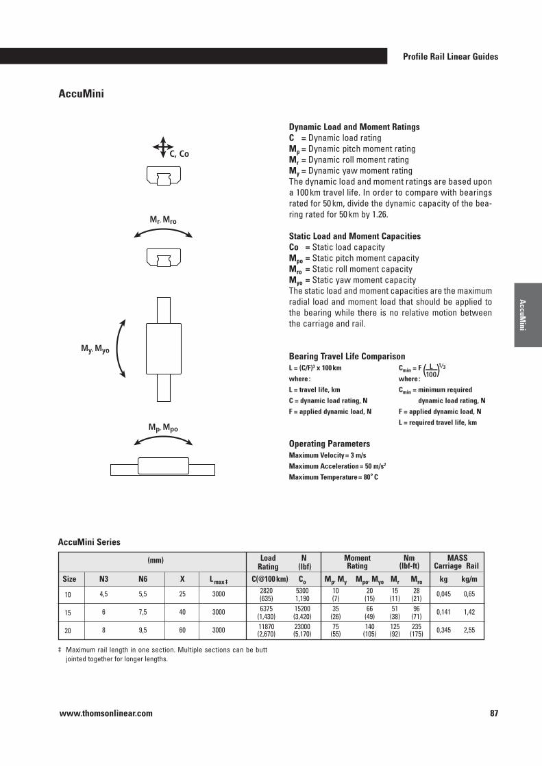
Profile Rail Linear Guides
www.thomsonlinear.com 87
AccuM
ini
AccuMini
Mr, Mro
Mp, Mpo
My, Myo
C, Co
‡ Maximum rail length in one section . Multiple sections can be butt jointed together for longer lengths .
Dynamic Load and Moment RatingsC = Dynamic load ratingMp = Dynamic pitch moment ratingMr = Dynamic roll moment ratingMy = Dynamic yaw moment ratingThe dynamic load and moment ratings are based upon a 100 km travel life . In order to compare with bearings rated for 50 km, divide the dynamic capacity of the bea-ring rated for 50 km by 1 .26 .
Static Load and Moment CapacitiesCo = Static load capacityMpo = Static pitch moment capacityMro = Static roll moment capacityMyo = Static yaw moment capacityThe static load and moment capacities are the maximum radial load and moment load that should be applied to the bearing while there is no relative motion between the carriage and rail .
MASS Carriage Rail
Moment Nm Rating (lbf-ft)
Load N Rating (lbf)
(mm)
Size N3 N6 X L max ‡ C(@100 km) Co Mp, My Mpo, Myo Mr Mro kg kg/m
10 4,5 5,5 25 3000 2820 5300 10 20 15 28 0,045 0,65 (635) 1,190 (7) (15) (11) (21)
15 6 7,5 40 3000 6375 15200 35 66 51 96 0,141 1,42 (1,430) (3,420) (26) (49) (38) (71)
20 8 9,5 60 3000 11870 23000 75 140 125 235 0,345 2,55 (2,670) (5,170) (55) (105) (92) (175)
Operating Parameters Maximum Velocity = 3 m/sMaximum Acceleration = 50 m/s2
Maximum Temperature = 80° C
L = (C/F)3 x 100 kmwhere :L = travel life, kmC = dynamic load rating, NF = applied dynamic load, N
Cmin = F ( ) L 100
1⁄3
where :Cmin = minimum required
dynamic load rating, NF = applied dynamic load, NL = required travel life, km
Bearing Travel Life Comparison
AccuMini Series
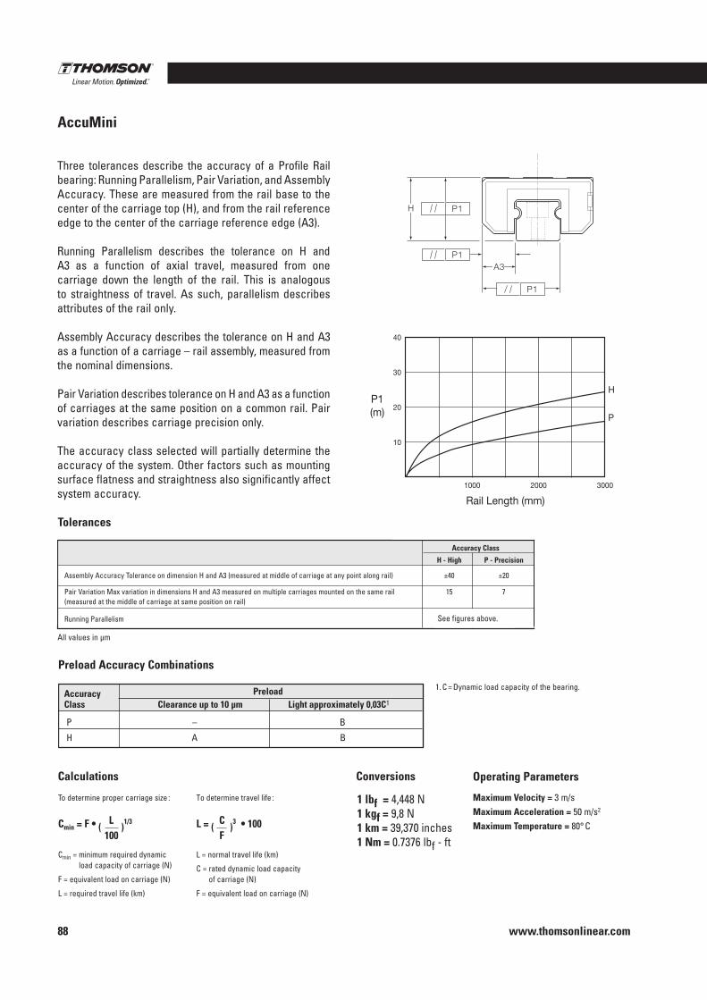
www.thomsonlinear.com88
Operating Parameters
Maximum Velocity = 3 m/sMaximum Acceleration = 50 m/s2
Maximum Temperature = 80° C
To determine proper carriage size :
Cmin = minimum required dynamic load capacity of carriage (N)
F = equivalent load on carriage (N)
L = required travel life (km)
To determine travel life :
L = normal travel life (km)
C = rated dynamic load capacity of carriage (N)
F = equivalent load on carriage (N)
Cmin = F • ( L )
1/3
100L = (
C )3 • 100
F
1 lbf = 4,448 N1 kgf = 9,8 N1 km = 39,370 inches1 Nm = 0 .7376 lbf - ft
Three tolerances describe the accuracy of a Profile Rail bearing: Running Parallelism, Pair Variation, and Assembly Accuracy . These are measured from the rail base to the center of the carriage top (H), and from the rail reference edge to the center of the carriage reference edge (A3) .
Running Parallelism describes the tolerance on H and A3 as a function of axial travel, measured from one carriage down the length of the rail . This is analogous to straightness of travel . As such, parallelism describes attributes of the rail only .
Assembly Accuracy describes the tolerance on H and A3 as a function of a carriage – rail assembly, measured from the nominal dimensions .
Pair Variation describes tolerance on H and A3 as a function of carriages at the same position on a common rail . Pair variation describes carriage precision only .
The accuracy class selected will partially determine the accuracy of the system . Other factors such as mounting surface flatness and straightness also significantly affect system accuracy .
Tolerances
All values in µm
Accuracy Class
H - High P - Precision Assembly Accuracy Tolerance on dimension H and A3 (measured at middle of carriage at any point along rail) ±40 ±20
Pair Variation Max variation in dimensions H and A3 measured on multiple carriages mounted on the same rail 15 7 (measured at the middle of carriage at same position on rail)
Running Parallelism
AccuMini
See figures above .
1 . C = Dynamic load capacity of the bearing .Accuracy Preload Class Clearance up to 10 µm Light approximately 0,03C1
P – B
H A B
ConversionsCalculations
Preload Accuracy Combinations
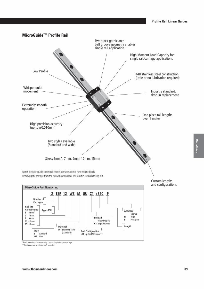
Profile Rail Linear Guides
www.thomsonlinear.com 89
MicroG
uide
High Moment Load Capacity for single rail/carriage applications
Two track gothic arch ball groove geometry enables single rail application
440 stainless steel construction (little or no lubrication required)
Industry standard, drop-in replacement
One piece rail lengths over 1 meter
Custom lengths and configurations
Two styles available (Standard and wide)
High precision accuracy (up to ±0.010mm)
Extremely smooth operation
Whisper quiet movement
Low Profile
Sizes: 5mm*, 7mm, 9mm, 12mm, 15mm
MicroGuide™ Profile Rail
MicroGuide Part Numbering
Number of Carriages
Types TSR
2 TSR 12 WZ M UU C1 P+350
Accuracy Normal H High P Precision
Length
Style Z StandardWZ Wide
5 5 mm*7 7 mm9 9 mm12 12 mm15 15 mm
Material M Stainless Steel (standard) Seal Configuration
UU Lip Seal Standard**
Preload Clearance Fit C1 Light Preload
Rail and Carriage Size
*For 5 mm size, there are only 2 mounting holes per carriage .**Seals are not available for 5 mm size .
Note! The Microguide linear guide series carriages do not have retained balls.
Removing the carriage from the rail without an arbor will result in the balls falling out.
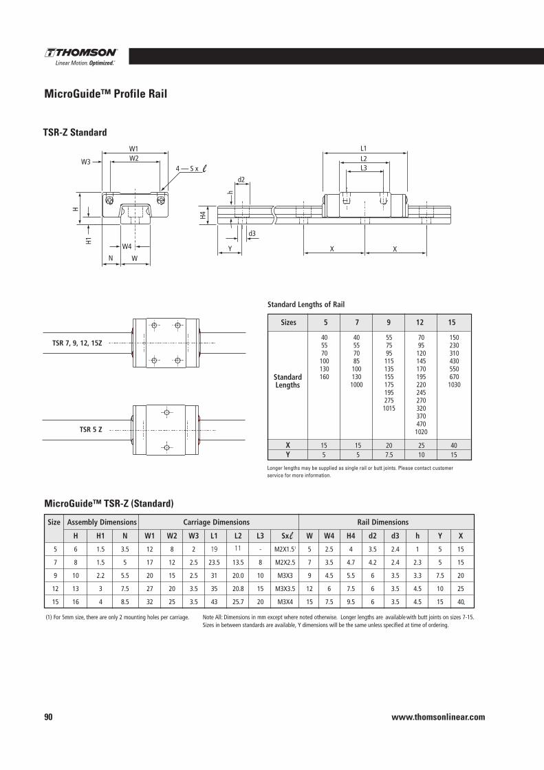
www.thomsonlinear.com90
MicroGuide™ Profile Rail
W1 W2
4 — S x W3
N W
W4
H1
H
L2 L1
L3
d2
h
H4
Y
d3
X X
TSR-Z Standard
TSR 7, 9, 12, 15Z
TSR 5 Z
MicroGuide™ TSR-Z (Standard)
Longer lengths may be supplied with butt-joints on sizes 7 through 15.
Standard Lengths of Rail
Sizes 5 7 9 12 15
X 15 15 20 25 40Y 5 5 7.5 10 15
Standard Lengths
405570100130160
405570851001301000
5575951151351551751952751015
70951201451701952202452703203704701020
1502303104305506701030
Size Assembly Dimensions Carriage Dimensions Rail Dimensions
H H1 N W1 W2 W3 L1 L2 L3 Sx W W4 H4 d2 d3 h Y X
5 6 1.5 3.5 12 8 2 17 12.8 - M2X1.51 5 2.5 4 3.5 2.4 1 5 15
7 8 1.5 5 17 12 2.5 23.5 13.5 8 M2X2.5 7 3.5 4.7 4.2 2.4 2.3 5 15
9 10 2.2 5.5 20 15 2.5 31 20.0 10 M3X3 9 4.5 5.5 6 3.5 3.3 7.5 20
12 13 3 7.5 27 20 3.5 35 20.8 15 M3X3.5 12 6 7.5 6 3.5 4.5 10 25
15 16 4 8.5 32 25 3.5 43 25.7 20 M3X4 15 7.5 9.5 6 3.5 4.5 15 40
(1) For 5mm size, there are only 2 mounting holes per carriage. Note All: Dimensions in mm except where noted otherwise. Longer lengths are available with butt joints on sizes 7-15.Sizes in between standards are available, Y dimensions will be the same unless specified at time of ordering.
Longer lengths may be supplied as single rail or butt joints . Please contact customer service for more information .
19 11
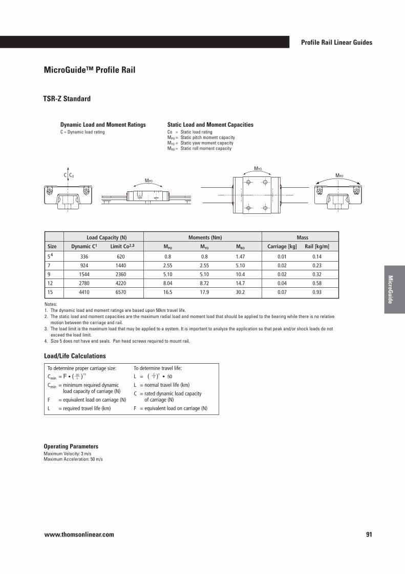
Profile Rail Linear Guides
www.thomsonlinear.com 91
MicroG
uide
TSR-Z Standard
Static Load and Moment CapacitiesCo = Static load ratingMpo = Static pitch moment capacityMyo = Static yaw moment capacityMro = Static roll moment capacity
Dynamic Load and Moment RatingsC = Dynamic load rating
MYO
MRO
MPO
C CO
Load Capacity (N) Moments (Nm) Mass
Size Dynamic C1
4
Limit Co2 MPO MYO MRO Carriage [kg] Rail [kg/m]
5 336 620 0.8 0.8 1.47 0.01 0.14
7 924 1440 2.55 2.55 5.10 0.02 0.23
9 1544 2360 5.10 5.10 10.4 0.02 0.32
12 2780 4220 8.04 8.72 14.7 0.04 0.58
15 4410 6570 16.5 17.9 30.2 0.07 0.93
Notes:1 . The dynamic load and moment ratings are based upon 50km travel life .2 . The static load and moment capacities are the maximum radial load and moment load that should be applied to the bearing while there is no relative
motion between the carriage and rail .3 . The load limit is the maximum load that may be applied to a system . It is important to analyze the application so that peak and/or shock loads do not
exceed the load limit .4 . Size 5 does not have end seals . Pan head screws required to mount rail .
,3
Operating ParametersMaximum Velocity: 3 m/sMaximum Acceleration: 50 m/s
MicroGuide™ Profile Rail
Load/Life Calculations
To determine proper carriage size:
Cmin = F • ( )1/3
Cmin = minimum required dynamicload capacity of carriage (N)
F = equivalent load on carriage (N)
L = required travel life (km)
50L
To determine travel life:
L = ( )3• 50
L = normal travel life (km)
C = rated dynamic load capacityof carriage (N)
F = equivalent load on carriage (N)
CF
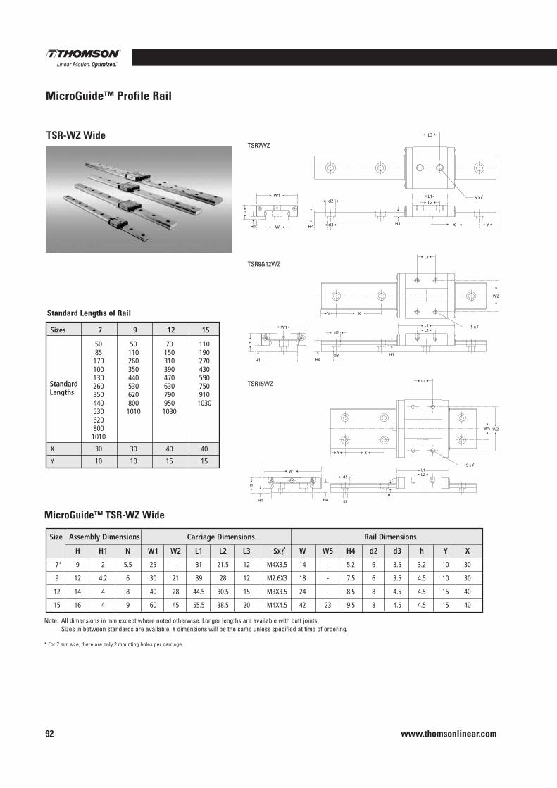
www.thomsonlinear.com92
TSR-WZ Wide
MicroGuide™ TSR-WZ Wide
Sizes 7 9 12 15
50 50 70 11085 110 150 190170 260 310 270100 350 390 430130 440 470 590260 530 630 750350 620 790 910440 800 950 1030530 1010 10306208001010
X 30 30 40 40
Y 10 10 15 15
StandardLengths
Size Assembly Dimensions Carriage Dimensions Rail Dimensions
H H1 N W1 W2 L1 L2 L3 Sx W W5 H4 d2 d3 h Y X
7 9* 2 5.5 25 - 31 21.5 12 M4X3.5 14 - 5.2 6 3.5 3.2 10 30
9 12 4.2 6 30 21 39 28 12 M2.6X3 18 - 7.5 6 3.5 4.5 10 30
12 14 4 8 40 28 44.5 30.5 15 M3X3.5 24 - 8.5 8 4.5 4.5 15 40
15 16 4 9 60 45 55.5 38.5 20 M4X4.5 42 23 9.5 8 4.5 4.5 15 40
Note: All dimensions in mm except where noted otherwise . Longer lengths are available with butt joints . Sizes in between standards are available, Y dimensions will be the same unless specified at time of ordering .
* For 7 mm size, there are only 2 mounting holes per carriage .
Standard Lengths of Rail
L3
L2L1
d2S x W1
W
H
H1 H4 d3 YXH1
L3
S x L2L1
W2
XY
H
W1d2
d3 H1
L3
W5
S x L1L2
XY
W1
H
d2
H1
W2
H1 H4
H1 H4
TSR7WZ
TSR9&12WZ
TSR15WZ
MicroGuide™ Profile Rail
d3
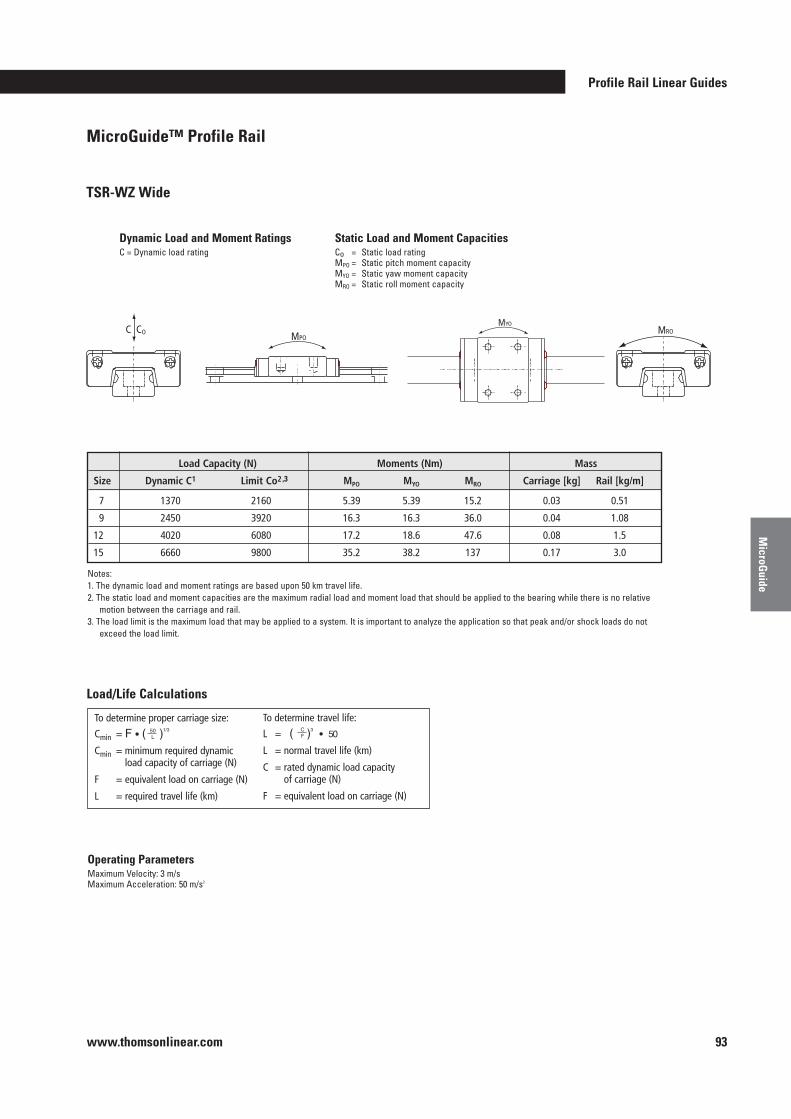
Profile Rail Linear Guides
www.thomsonlinear.com 93
MicroG
uide
Static Load and Moment CapacitiesCo = Static load ratingMpo = Static pitch moment capacityMyo = Static yaw moment capacityMro = Static roll moment capacity
Dynamic Load and Moment RatingsC = Dynamic load rating
MROMPO
MYO C CO
Load Capacity (N) Moments (Nm) Mass
Size Dynamic C1 Limit Co2 MPO MYO MRO Carriage [kg] Rail [kg/m]
7 1370 2160 5.39 5.39 15.2 0.03 0.51
9 2450 3920 16.3 16.3 36.0 0.04 1.08
12 4020 6080 17.2 18.6 47.6 0.08 1.5
15 6660 9800 35.2 38.2 137 0.17 3.0
Notes:1 . The dynamic load and moment ratings are based upon 50 km travel life .2 . The static load and moment capacities are the maximum radial load and moment load that should be applied to the bearing while there is no relative
motion between the carriage and rail .3 . The load limit is the maximum load that may be applied to a system . It is important to analyze the application so that peak and/or shock loads do not
exceed the load limit .
Operating ParametersMaximum Velocity: 3 m/sMaximum Acceleration: 50 m/s2
Load/Life Calculations
To determine proper carriage size:
Cmin = F • ( )1/3
Cmin = minimum required dynamicload capacity of carriage (N)
F = equivalent load on carriage (N)
L = required travel life (km)
50L
To determine travel life:
L = ( )3• 50
L = normal travel life (km)
C = rated dynamic load capacityof carriage (N)
F = equivalent load on carriage (N)
CF
TSR-WZ Wide
MicroGuide™ Profile Rail
,3
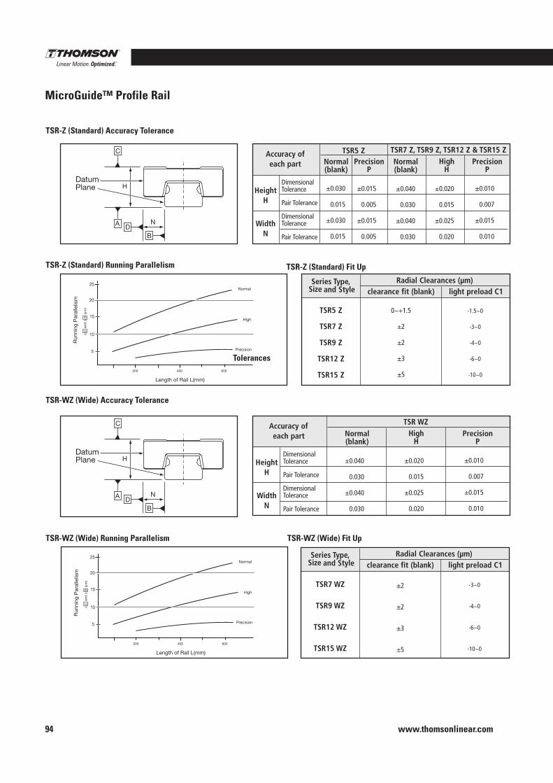
www.thomsonlinear.com94
PrecisionP
N
H
C
B
A D
DatumPlane
25
20
15
10
5
Run
ning
Par
alle
lism
Length of Rail L(mm)
Normal
High
Precision
200 400 600
∆ C
and
∆ D
(µm
)
Dimensional Tolerance
Pair Tolerance
DimensionalTolerance
Pair Tolerance
Normal(blank)
Accuracy of each part
Series Type,Size and Style
TSR5 Z
TSR7 Z
TSR9 Z
TSR12 Z
TSR15 Z
0~+1.5
±2
±2
±3
±5
-1.5~0
-3~0
-4~0
-6~0
-10~0
High H
Radial Clearances (µm)clearance fit (blank) light preload C1
Series Type,Size and Style
TSR7 WZ
TSR9 WZ
TSR12 WZ
TSR15 WZ
±2
±2
±3
±5
-3~0
-4~0
-6~0
-10~0
Radial Clearances (µm)clearance fit (blank) light preload C1
Normal(blank)
PrecisionP
HeightH
WidthN
Dimensional Tolerance
Pair Tolerance
DimensionalTolerance
Pair Tolerance
Accuracy of each part
HeightH
WidthN
TSR WZ
±0.040
0.030
±0.040
0.030
±0.020
0.015
±0.025
0.020
±0.010
0.007
±0.015
0.010
Normal(blank)
PrecisionP
High H
±0.030
0.015
±0.030
0.015
±0.015
0.005
±0.015
0.005
±0.040
0.030
±0.040
0.030
±0.020
0.015
±0.025
0.020
±0.010
0.007
±0.015
0.010
TSR7 Z, TSR9 Z, TSR12 Z & TSR15 ZTSR5 Z
N
H
C
B
A D
DatumPlane
25
20
15
10
5
Run
ning
Par
alle
lism
Length of Rail L(mm)
Normal
High
Precision
200 400 600
∆ C
and
∆ D
(µm
)
Tolerances
TSR-Z (Standard) Fit Up
TSR-Z (Standard) Accuracy Tolerance
TSR-WZ (Wide) Accuracy Tolerance
TSR-Z (Standard) Running Parallelism
TSR-WZ (Wide) Running Parallelism TSR-WZ (Wide) Fit Up
MicroGuide™ Profile Rail
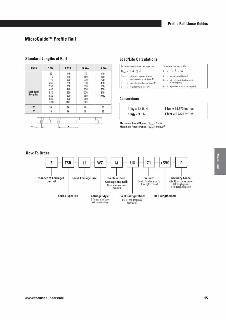
Profile Rail Linear Guides
www.thomsonlinear.com 95
MicroG
uide
PrecisionP
N
H
C
B
A D
DatumPlane
25
20
15
10
5
Run
ning
Par
alle
lism
Length of Rail L(mm)
Normal
High
Precision
200 400 600
∆ C
and
∆ D
(µm
)
Dimensional Tolerance
Pair Tolerance
DimensionalTolerance
Pair Tolerance
Normal(blank)
Accuracy of each part
Series Type,Size and Style
TSR5 Z
TSR7 Z
TSR9 Z
TSR12 Z
TSR15 Z
0~+1.5
±2
±2
±3
±5
-1.5~0
-3~0
-4~0
-6~0
-10~0
High H
Radial Clearances (µm)clearance fit (blank) light preload C1
Series Type,Size and Style
TSR7 WZ
TSR9 WZ
TSR12 WZ
TSR15 WZ
±2
±2
±3
±5
-3~0
-4~0
-6~0
-10~0
Radial Clearances (µm)clearance fit (blank) light preload C1
Normal(blank)
PrecisionP
HeightH
WidthN
Dimensional Tolerance
Pair Tolerance
DimensionalTolerance
Pair Tolerance
Accuracy of each part
HeightH
WidthN
TSR WZ
±0.040
0.030
±0.040
0.030
±0.020
0.015
±0.025
0.020
±0.010
0.007
±0.015
0.010
Normal(blank)
PrecisionP
High H
±0.030
0.015
±0.030
0.015
±0.015
0.005
±0.015
0.005
±0.040
0.030
±0.040
0.030
±0.020
0.015
±0.025
0.020
±0.010
0.007
±0.015
0.010
TSR7 Z, TSR9 Z, TSR12 Z & TSR15 ZTSR5 Z
N
H
C
B
A D
DatumPlane
25
20
15
10
5
Run
ning
Par
alle
lism
Length of Rail L(mm)
Normal
High
Precision
200 400 600
∆ C
and
∆ D
(µm
)
Tolerances
Standard Lengths of Rail Load/Life Calculations
Sizes 7 WZ 9 WZ 12 WZ 15 WZ
X 30 30 40 40 Y 10 10 15 15
Standard Lengths
501101702603504405306208001010
50110170260350440530620800
1010
70150230310390470630790950
1030
110190270430590750910
1030
To determine proper carriage size:
Cmin = F • ( ) 1/3
Cmin = minimum required dynamic load capacity of carriage (N)
F = equivalent load on carriage (N)
L = required travel life (km)
50L
To determine travel life:
L = ( ) 3 • 50
L = normal travel life (km)
C = rated dynamic load capacity of carriage (N)
F = equivalent load on carriage (N)
CF
1 lbf = 4 .448 N1 kgf = 9 .8 N
Maximum Travel Speed: Vmax = 3 m/sMaximum Acceleration: a max = 50 m/s2
1 km = 39,370 inches1 Nm = 0 .7376 lbf - ft
Conversions
Z for standard styleWZ for wide style
M for stainless steel(standard)
UU for end seals only(standard)
(blank) for clearance fitC1 for light preload
(blank) for normal gradeH for high grade
P for precision grade
How To Order
MicroGuide™ Profile Rail
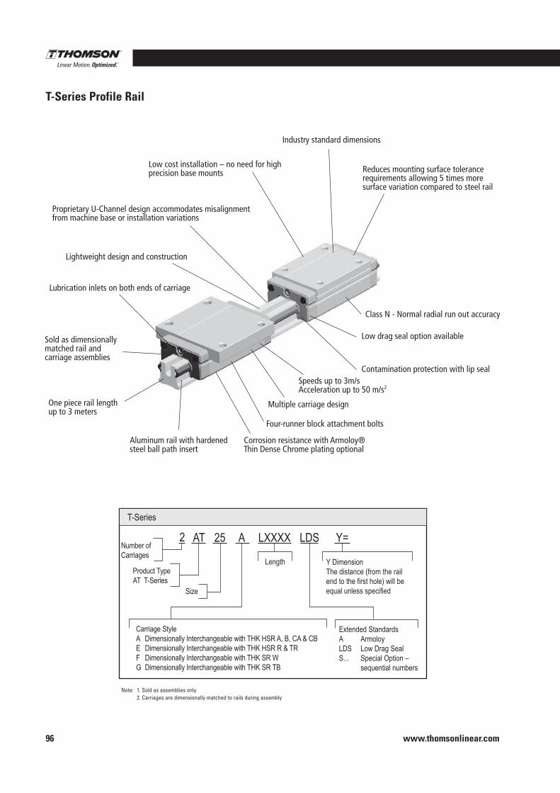
www.thomsonlinear.com96
T-Series Profile Rail
Note: 1 . Sold as assemblies only 2 . Carriages are dimensionally matched to rails during assembly
Industry standard dimensions
Reduces mounting surface tolerance requirements allowing 5 times moresurface variation compared to steel rail
Class N - Normal radial run out accuracy
Low drag seal option available
Contamination protection with lip seal Speeds up to 3m/s Acceleration up to 50 m/s2
Multiple carriage design
Four-runner block attachment bolts
Aluminum rail with hardened steel ball path insert
One piece rail length up to 3 meters
Sold as dimensionally matched rail and carriage assemblies
Lubrication inlets on both ends of carriage
Lightweight design and construction
Low cost installation – no need for high precision base mounts
Proprietary U-Channel design accommodates misalignment from machine base or installation variations
Corrosion resistance with Armoloy®Thin Dense Chrome plating optional
T-Series
Product TypeAT T-Series
Size
AT 25 A LXXXX LDS
Carriage StyleA Dimensionally Interchangeable with THK HSR A, B, CA & CBE Dimensionally Interchangeable with THK HSR R & TRF Dimensionally Interchangeable with THK SR WG Dimensionally Interchangeable with THK SR TB
Length
Y=2Number ofCarriages
Y DimensionThe distance (from the rail end to the first hole) will be equal unless specified
Extended StandardsA ArmoloyLDS Low Drag SealS... Special Option – sequential numbers
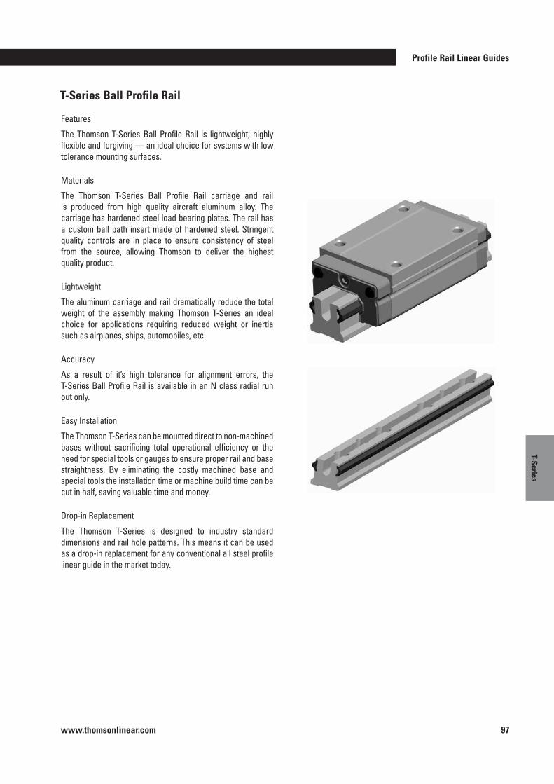
Profile Rail Linear Guides
www.thomsonlinear.com 97
T-Series
T-Series Ball Profile Rail
Features
The Thomson T-Series Ball Profile Rail is lightweight, highly flexible and forgiving — an ideal choice for systems with low tolerance mounting surfaces .
Materials
The Thomson T-Series Ball Profile Rail carriage and rail is produced from high quality aircraft aluminum alloy . The carriage has hardened steel load bearing plates . The rail has a custom ball path insert made of hardened steel . Stringent quality controls are in place to ensure consistency of steel from the source, allowing Thomson to deliver the highest quality product .
Lightweight
The aluminum carriage and rail dramatically reduce the total weight of the assembly making Thomson T-Series an ideal choice for applications requiring reduced weight or inertia such as airplanes, ships, automobiles, etc .
Accuracy
As a result of it’s high tolerance for alignment errors, the T-Series Ball Profile Rail is available in an N class radial run out only .
Easy Installation
The Thomson T-Series can be mounted direct to non-machined bases without sacrificing total operational efficiency or the need for special tools or gauges to ensure proper rail and base straightness . By eliminating the costly machined base and special tools the installation time or machine build time can be cut in half, saving valuable time and money .
Drop-in Replacement
The Thomson T-Series is designed to industry standard dimensions and rail hole patterns . This means it can be used as a drop-in replacement for any conventional all steel profile linear guide in the market today .
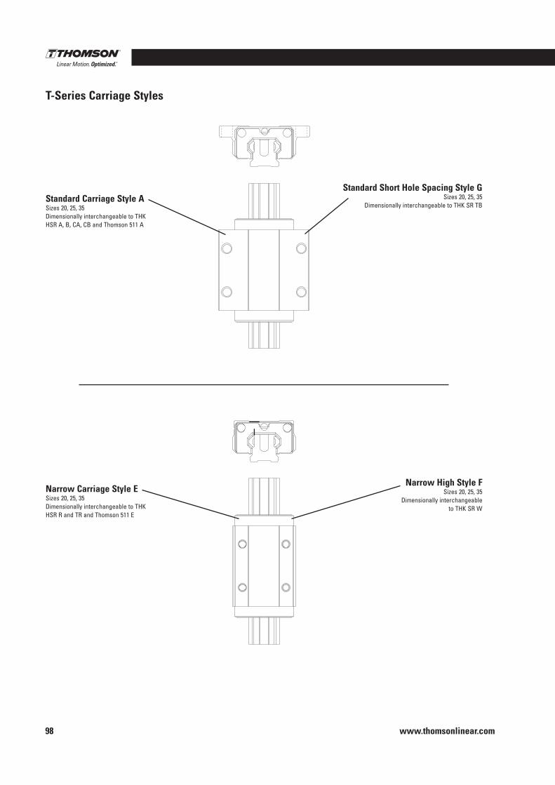
www.thomsonlinear.com98
T-Series Carriage Styles
Standard Carriage Style ASizes 20, 25, 35Dimensionally interchangeable to THK HSR A, B, CA, CB and Thomson 511 A
Standard Short Hole Spacing Style GSizes 20, 25, 35
Dimensionally interchangeable to THK SR TB
Narrow Carriage Style ESizes 20, 25, 35Dimensionally interchangeable to THK HSR R and TR and Thomson 511 E
Narrow High Style FSizes 20, 25, 35
Dimensionally interchangeable to THK SR W
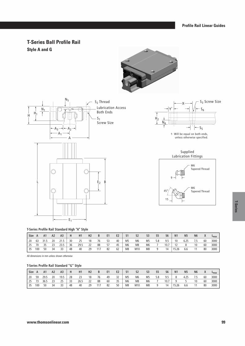
Profile Rail Linear Guides
www.thomsonlinear.com 99
T-Series
T-Series Ball Profile RailStyle A and G
A2A1
A
A3
H1H
E1
E2 BL
S2 Thread
S1Screw Size
N1
M6 Tapered Thread
M6 Tapered Thread
9
15
45
SuppliedLubrication Fittings
Lubrication AccessBoth Ends
S5
X
Y†
N6
H2
S6
S3 Screw Size
†- Will be equal on both ends, unless otherwise specified.
N5
T-Series Profile Rail Standard High “A” Style
Size A A1 A2 A3 H H1 H2 B E1 E2 S1 S2 S3 S5 S6 N1 N5 N6 X Lmax
20 63 31.5 20 21.5 30 25 18 76 53 40 M5 M6 M5 5.8 9.5 10 6.25 7,5 60 300025 70 35 23 23.5 36 29.5 22 88 57 45 M6 M8 M6 7 10.7 12 8 10 60 300035 100 50 34 33 48 40 29 117 82 62 M8 M10 M8 9 14 15.26 6.6 11 80 3000
T-Series Profile Rail Standard “G” Style
Size A A1 A2 A3 H H1 H2 B E1 E2 S1 S2 S3 S5 S6 N1 N5 N6 X Lmax
20 59 29.5 20 19.5 28 23 18 76 49 32 M5 M6 M5 5.8 9.5 8 4.25 7.5 60 300025 73 36.5 23 25 33 26.5 22 88 60 35 M6 M8 M6 7 10.7 9 5 10 60 300035 100 50 34 33 48 40 29 117 82 50 M8 M10 M8 9 14 15.26 6.6 11 80 3000
All dimensions in mm unless shown otherwise
All dimensions in mm unless shown otherwise
°
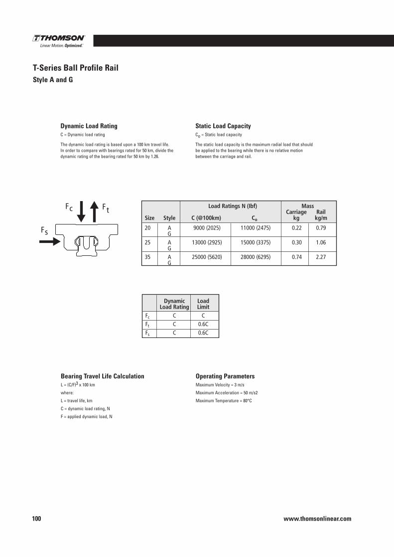
www.thomsonlinear.com100
T-Series Ball Profile RailStyle A and G
Static Load CapacityCo = Static load capacity
The static load capacity is the maximum radial load that should be applied to the bearing while there is no relative motion between the carriage and rail .
Dynamic Load RatingC = Dynamic load rating
The dynamic load rating is based upon a 100 km travel life . In order to compare with bearings rated for 50 km, divide the dynamic rating of the bearing rated for 50 km by 1 .26 .
Operating ParametersMaximum Velocity = 3 m/s
Maximum Acceleration = 50 m/s2
Maximum Temperature = 80°C
Bearing Travel Life CalculationL = (C/F)3 x 100 km
where:
L = travel life, km
C = dynamic load rating, N
F = applied dynamic load, N
Fc Ft
Fs
Load Ratings N (Ibf) MassCarriage Rail
Size Style C (@100km) Co kg kg/m
20 A 9000 (2025) 11000 (2475) 0.22 0.79G
25 A 13000 (2925) 15000 (3375) 0.30 1.06G
35 A 25000 (5620) 28000 (6295) 0.74 2.27G
Dynamic LoadLoad Rating Limit
Fc C CFt C 0.6CFs C 0.6C
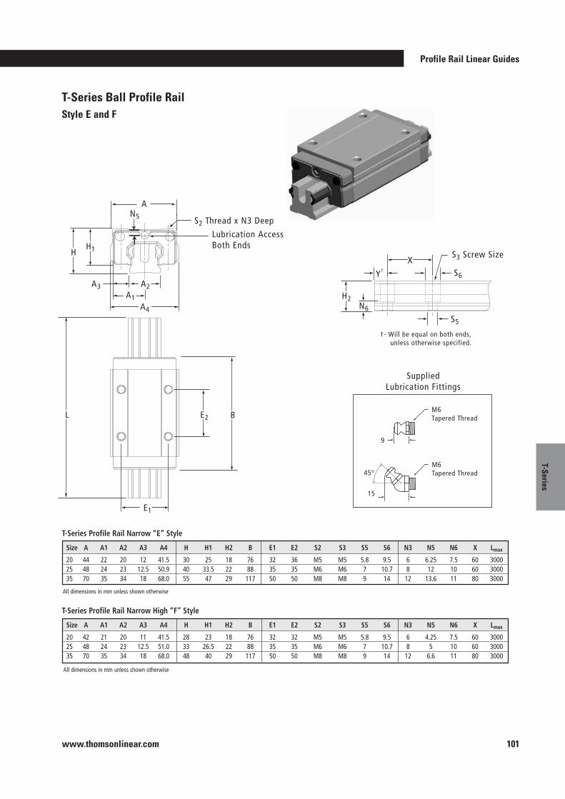
Profile Rail Linear Guides
www.thomsonlinear.com 101
T-Series
S2 Thread x N3 Deep
Lubrication AccessBoth Ends
S5
†- Will be equal on both ends, unless otherwise specified.
S6
S3 Screw SizeX
Y†
N6
H2
SuppliedLubrication Fittings
M6 Tapered Thread
M6 Tapered Thread
9
15
45°
E1
E2 BL
N5
A
A2A1
A3
H1H
A4
T-Series Ball Profile RailStyle E and F
T-Series Profile Rail Narrow “E” Style
Size A A1 A2 A3 A4 H H1 H2 B E1 E2 S2 S3 S5 S6 N3 N5 N6 X Lmax
20 44 22 20 12 41.5 30 25 18 76 32 36 M5 M5 5.8 9.5 6 6.25 7.5 60 300025 48 24 23 12.5 50.9 40 33.5 22 88 35 35 M6 M6 7 10.7 8 12 10 60 300035 70 35 34 18 68.0 55 47 29 117 50 50 M8 M8 9 14 12 13.6 11 80 3000
T-Series Profile Rail Narrow High “F” Style
Size A A1 A2 A3 A4 H H1 H2 B E1 E2 S2 S3 S5 S6 N3 N5 N6 X Lmax
20 42 21 20 11 41.5 28 23 18 76 32 32 M5 M5 5.8 9.5 6 4.25 7.5 60 300025 48 24 23 12.5 51.0 33 26.5 22 88 35 35 M6 M6 7 10.7 8 5 10 60 300035 70 35 34 18 68.0 48 40 29 117 50 50 M8 M8 9 14 12 6.6 11 80 3000
All dimensions in mm unless shown otherwise
All dimensions in mm unless shown otherwise
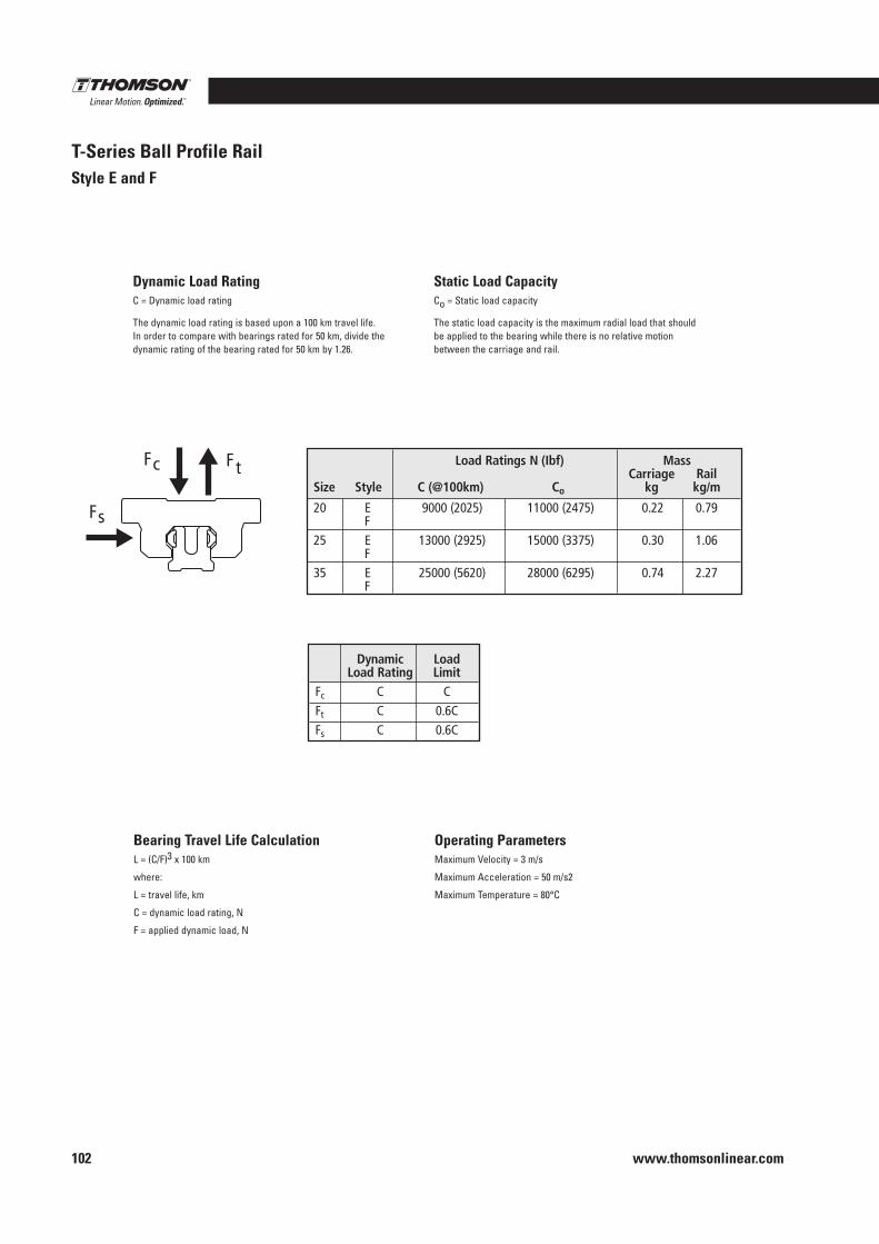
www.thomsonlinear.com102
T-Series Ball Profile RailStyle E and F
Static Load CapacityCo = Static load capacity
The static load capacity is the maximum radial load that should be applied to the bearing while there is no relative motion between the carriage and rail .
Dynamic Load RatingC = Dynamic load rating
The dynamic load rating is based upon a 100 km travel life . In order to compare with bearings rated for 50 km, divide the dynamic rating of the bearing rated for 50 km by 1 .26 .
Operating ParametersMaximum Velocity = 3 m/s
Maximum Acceleration = 50 m/s2
Maximum Temperature = 80°C
Bearing Travel Life CalculationL = (C/F)3 x 100 km
where:
L = travel life, km
C = dynamic load rating, N
F = applied dynamic load, N
Fc Ft
Fs
Dynamic LoadLoad Rating Limit
Fc C CFt C 0.6CFs C 0.6C
Load Ratings N (Ibf) MassCarriage Rail
Size Style C (@100km) Co kg kg/m
20 E 9000 (2025) 11000 (2475) 0.22 0.79F
25 E 13000 (2925) 15000 (3375) 0.30 1.06F
35 E 25000 (5620) 28000 (6295) 0.74 2.27F
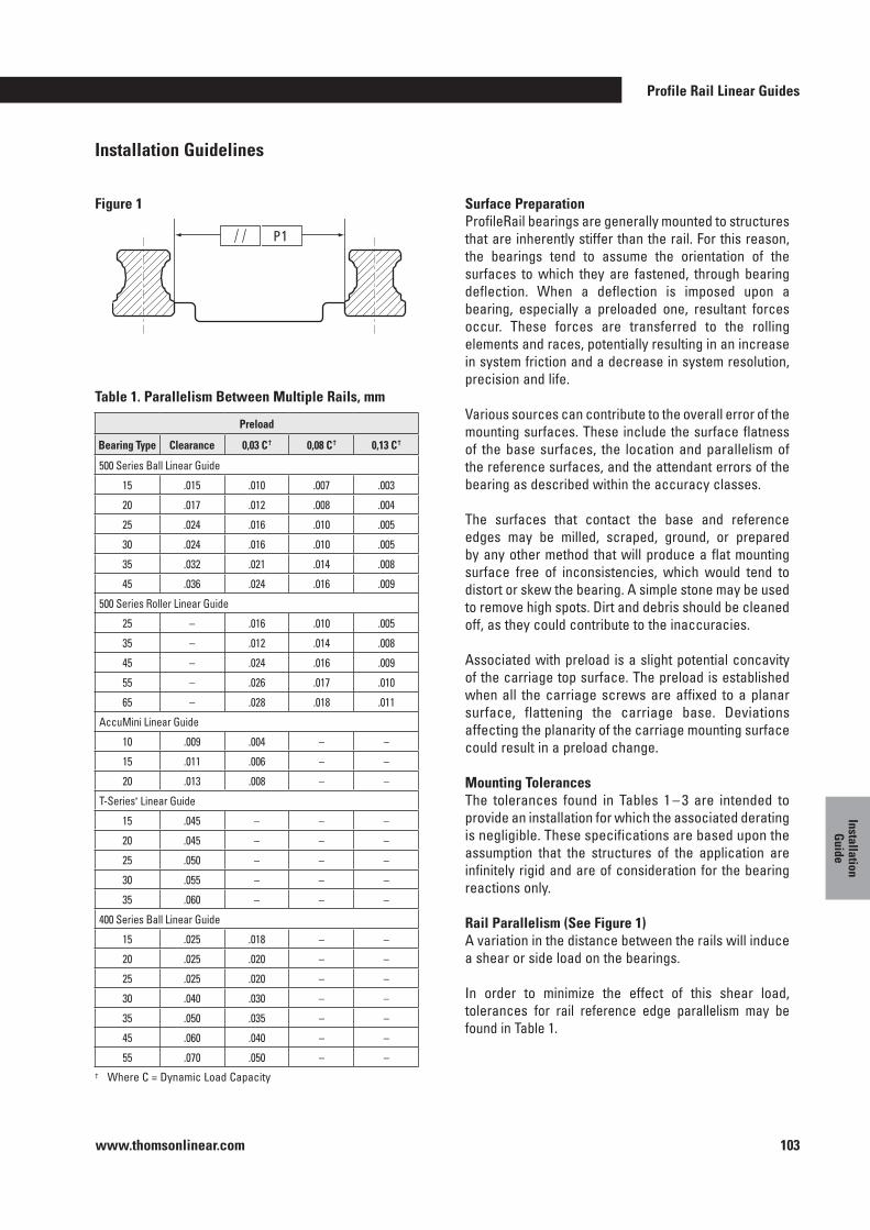
Profile Rail Linear Guides
www.thomsonlinear.com 103
Installation G
uide
Installation Guidelines
Surface PreparationProfileRail bearings are generally mounted to structures that are inherently stiffer than the rail . For this reason, the bearings tend to assume the orientation of the surfaces to which they are fastened, through bearing deflection . When a deflection is imposed upon a bearing, especially a preloaded one, resultant forces occur . These forces are transferred to the rolling elements and races, potentially resulting in an increase in system friction and a decrease in system resolution, precision and life .
Various sources can contribute to the overall error of the mounting surfaces . These include the surface flatness of the base surfaces, the location and parallelism of the reference surfaces, and the attendant errors of the bearing as described within the accuracy classes .
The surfaces that contact the base and reference edges may be milled, scraped, ground, or prepared by any other method that will produce a flat mounting surface free of inconsistencies, which would tend to distort or skew the bearing . A simple stone may be used to remove high spots . Dirt and debris should be cleaned off, as they could contribute to the inaccuracies .
Associated with preload is a slight potential concavity of the carriage top surface . The preload is established when all the carriage screws are affixed to a planar surface, flattening the carriage base . Deviations affecting the planarity of the carriage mounting surface could result in a preload change .
Mounting TolerancesThe tolerances found in Tables 1 – 3 are intended to provide an installation for which the associated derating is negligible . These specifications are based upon the assumption that the structures of the application are infinitely rigid and are of consideration for the bearing reactions only .
Rail Parallelism (See Figure 1)A variation in the distance between the rails will induce a shear or side load on the bearings .
In order to minimize the effect of this shear load, tolerances for rail reference edge parallelism may be found in Table 1 .
Table 1 . Parallelism Between Multiple Rails, mm
Figure 1
P1
† Where C = Dynamic Load Capacity
Preload
Bearing Type Clearance 0,03 C † 0,08 C † 0,13 C †
500 Series Ball Linear Guide
15 .015 .010 .007 .003
20 .017 .012 .008 .004
25 .024 .016 .010 .005
30 .024 .016 .010 .005
35 .032 .021 .014 .008
45 .036 .024 .016 .009
500 Series Roller Linear Guide
25 – .016 .010 .005
35 – .012 .014 .008
45 – .024 .016 .009
55 – .026 .017 .010
65 – .028 .018 .011
AccuMini Linear Guide
10 .009 .004 – –
15 .011 .006 – –
20 .013 .008 – –
T-Series* Linear Guide
15 .045 – – –
20 .045 – – –
25 .050 – – –
30 .055 – – –
35 .060 – – –
400 Series Ball Linear Guide
15 .025 .018 – –
20 .025 .020 – –
25 .025 .020 – –
30 .040 .030 – –
35 .050 .035 – –
45 .060 .040 – –
55 .070 .050 – –

www.thomsonlinear.com104
Rail Vertical Offset (See Figure 2)A vertical offset of the rails across the axis will induce a roll moment onto the carriages .
To minimize the effect of this roll moment, tolerances for the vertical offset may be found in Table 2 . This tolerance describes the attributes of the mounting surface, perpen dicular to the rail axis .
Vertical Carriage Offset (See Figure 3)A vertical offset between fore and aft carriages will induce a pitch moment on the bearings .
Lateral Carriage Offset (See Figure 4)A lateral offset of the carriage reference edges will induce a yaw moment .
In order to minimize the effects of these pitch and yaw moments, tolerances may be found in Table 3 . This tolerance describes the attributes of the mounting surface parallel to the rail axis, and the reference edge straightness .
NOTE : All mounting tolerances should be inclusive of the H and A3 tolerances . Thus, a lower accuracy class bearing may require a more accurate installation .
Mounting Hole TolerancesThe positional tolerance between the through holes in the rails is 0 .5 mm .
The positional tolerance of the first rail mounting hole dimensioned from the datum end (called the “Y-dimension”) is ±1 .0 mm .
The overall rail length tolerance is ±2 .0 mm .
The positional tolerance between the mounting holes in the carriages is 0 .2 mm .
Reference Edge SpecificationsThe maximum shoulder heights and corner radii are listed in Table 4 .
a S1
Figure 2
Figure 3
b
S2
Figure 4
Installation Guidelines
† Where C = Dynamic Load Capacity
Table 2 . Allowable Vertical Offsets Between Rails (S1/a), inch
Preload
Bearing Type Clearance 0 .03 C † 0 .08 C † 0 .13 C †
500 Series Ball 0 .0006 0 .0004 0,0003 0 .0002
500 Series Roller – 0 .0007 0 .0005 0 .0004
AccuMini Linear Guide 0 .0006 0 .0004 – –
T-Series Linear Guide 0 .0020 – – –
400 Series 15, 20 & 25 0 .0050 0 .0030 – –
400 Series 30 0 .0060 0 .0040 – –
400 Series 35 0 .0080 0 .0050 – –
400 Series 45 0 .0090 0 .0060 – –
400 Series 55 0 .0118 0 .0080 – –
Table 3 . Allowable Carriage Offsets (S2/b)
† Where C=Dynamic Load Capacity
T-Series Linear Guide 0,00012
Preload
Bearing Type Clearance 0 .03 C † 0 .08 C † 0 .13 C †
500 Series (All) 0,00006 0,00005 0,00004 0,00003400 Series 15 & 20 0 .0009 0 .0007 – –400 Series 25 0 .0011 0 .0008 – –400 Series 30 0 .0015 0 .0011 – –400 Series 35 0 .0019 0 .0013 – –400 Series 45 0 .0023 0 .0015 – –400 Series 55 0 .0027 0 .0017 – –
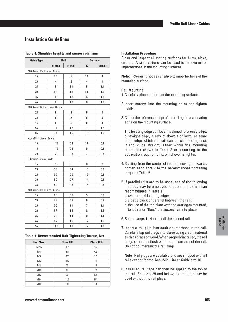
Profile Rail Linear Guides
www.thomsonlinear.com 105
Installation G
uide
Installation ProcedureClean and inspect all mating surfaces for burrs, nicks, dirt, etc . A simple stone can be used to remove minor imperfections in the mounting surfaces .
Note : T-Series is not as sensitive to imperfections of the mounting surface .
Rail Mounting1 . Carefully place the rail on the mounting surface .
2 . Insert screws into the mounting holes and tighten lightly .
3 . Clamp the reference edge of the rail against a locating edge on the mounting surface .
The locating edge can be a machined reference edge, a straight edge, a row of dowels or keys, or some other edge which the rail can be clamped against . It should be straight, either within the mounting tolerances shown in Table 3 or according to the application requirements, whichever is tighter .
4 . Starting from the center of the rail moving outwards, tighten each screw to the recommended tightening torque in Table 5 .
5 . If parallel rails are to be used, one of the following methods may be employed to obtain the parallelism recommended in Table 1 :
a . two parallel locating edges b . a gage block or parallel between the rails c . the use of the top plate with the carriages mounted,
to locate or “float” the second rail into place .
6 . Repeat steps 1 – 4 to install the second rail .
7 . Insert a rail plug into each counterbore in the rail . Carefully tap rail plugs into place using a soft material such as brass or wood . When properly installed, the rail plugs should be flush with the top surface of the rail . Do not countersink the rail plugs .
Note : Rail plugs are available and are shipped with all rails except for the AccuMini Linear Guide size 10 .
8 . If desired, rail tape can then be applied to the top of the rail . For sizes 35 and below, the rail tape may be used without the rail plugs .
Bolt Size Class 8 .8 Class 12 .9 M2 .5 0 .7 1 .2
M4 2 .8 4 .6
M5 5 .7 9 .5
M6 9 .5 16
M8 23 39
M10 46 77
M12 80 135
M14 129 215
M16 198 330
Table 4 . Shoulder heights and corner radii, mm
Table 5 . Recommended Bolt Tightening Torque, Nm
Guide Type Rail Carriage
h1 max r1 max h2 r2 max
500 Series Ball Linear Guide
15 3 .5 .8 3 .5 .6
20 4 .9 4 .9
25 5 1 .1 5 1 .1
30 5 .5 1 .3 5 .5 1 .3
35 6 1 .3 6 1 .3
45 8 1 .3 8 1 .3
500 Series Roller Linear Guide
25 5 .8 5 .8
35 6 .8 6 .8
45 8 .8 8 .8
55 10 1 .2 10 1 .2
65 10 1 .5 10 1 .5
AccuMini Linear Guide
10 1 .75 0 .4 3 .5 0 .4
15 1 .75 0 .4 5 0 .4
20 2 0 .5 7 0 .5
T-Series* Linear Guide
15 3 .3 8 .2
20 3 .9 0 .4 10 0 .3
25 5 .5 0 .5 12 0 .4
30 5 .9 0 .7 14 0 .5
35 5 .9 0 .8 15 0 .6
400 Series Ball Linear Guide
15 2 .8 0 .6 5 0 .6
20 4 .3 0 .9 6 0 .9
25 5 .6 1 .1 7 1 .1
30 6 .8 1 .4 8 1 .4
35 7 .3 1 .4 9 1 .4
45 8 .7 1 .6 12 1 .6
55 11 .8 1 .6 17 1 .6
Installation Guidelines
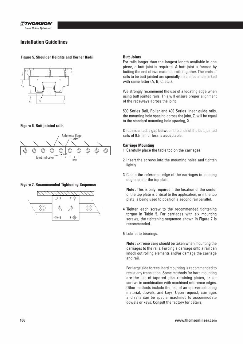
www.thomsonlinear.com106
Butt JointsFor rails longer than the longest length available in one piece, a butt joint is required . A butt joint is formed by butting the end of two matched rails together . The ends of rails to be butt jointed are specially machined and marked with same letter (A, B, C, etc .) .
We strongly recommend the use of a locating edge when using butt jointed rails . This will ensure proper alignment of the raceways across the joint .
500 Series Ball, Roller and 400 Series linear guide rails, the mounting hole spacing across the joint, Z, will be equal to the standard mounting hole spacing, X . Once mounted, a gap between the ends of the butt jointed rails of 0 .5 mm or less is acceptable .
Carriage Mounting1 . Carefully place the table top on the carriages .
2 . Insert the screws into the mounting holes and tighten lightly .
3 . Clamp the reference edge of the carriages to locating edges under the top plate .
Note : This is only required if the location of the center of the top plate is critical to the application, or if the top plate is being used to position a second rail parallel .
4 . Tighten each screw to the recommended tightening torque in Table 5 . For carriages with six mounting screws, the tightening sequence shown in Figure 7 is recommended .
5 . Lubricate bearings .
Note : Extreme care should be taken when mounting the carriages to the rails . Forcing a carriage onto a rail can knock out rolling elements and/or damage the carriage and rail .
For large side forces, hard mounting is recommended to resist any translation . Some methods for hard mounting are the use of tapered gibs, retaining plates, or set screws in combination with machined reference edges . Other methods include the use of an epoxy/replicating material, dowels, and keys . Upon request, carriages and rails can be special machined to accommodate dowels or keys . Consult the factory for details .
Z A A
Reference Edge Joint
Joint Indicator X (TYP)
1
3 4
5 6
2
Figure 6 . Butt jointed rails
Figure 7 . Recommended Tightening Sequence
Installation Guidelines
h1 r1
r2
h2
Figure 5 . Shoulder Heights and Corner Radii
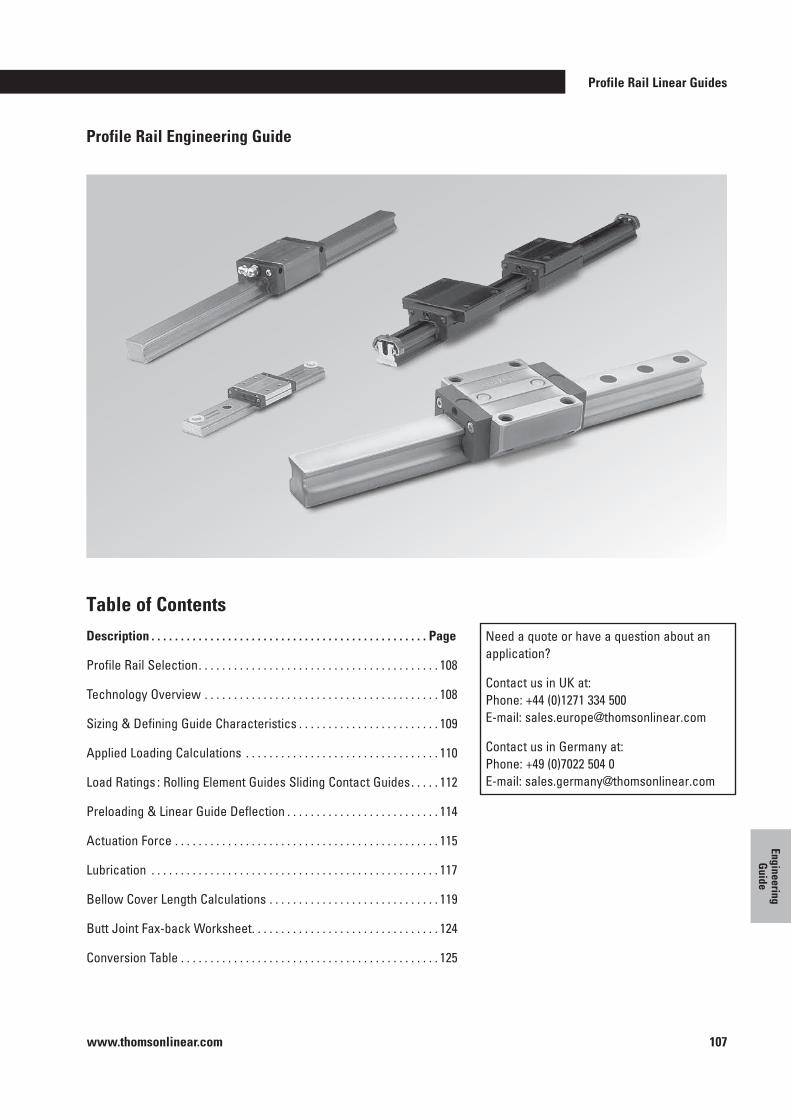
Profile Rail Linear Guides
www.thomsonlinear.com 107
Engineering G
uide
Profile Rail Engineering Guide
Table of ContentsDescription . . . . . . . . . . . . . . . . . . . . . . . . . . . . . . . . . . . . . . . . . . . . . . . Page
Profile Rail Selection . . . . . . . . . . . . . . . . . . . . . . . . . . . . . . . . . . . . . . . . . 108
Technology Overview . . . . . . . . . . . . . . . . . . . . . . . . . . . . . . . . . . . . . . . . 108
Sizing & Defining Guide Characteristics . . . . . . . . . . . . . . . . . . . . . . . . 109
Applied Loading Calculations . . . . . . . . . . . . . . . . . . . . . . . . . . . . . . . . . 110
Load Ratings : Rolling Element Guides Sliding Contact Guides . . . . . 112
Preloading & Linear Guide Deflection . . . . . . . . . . . . . . . . . . . . . . . . . . 114
Actuation Force . . . . . . . . . . . . . . . . . . . . . . . . . . . . . . . . . . . . . . . . . . . . . 115
Lubrication . . . . . . . . . . . . . . . . . . . . . . . . . . . . . . . . . . . . . . . . . . . . . . . . . 117
Bellow Cover Length Calculations . . . . . . . . . . . . . . . . . . . . . . . . . . . . . 119
Butt Joint Fax-back Worksheet . . . . . . . . . . . . . . . . . . . . . . . . . . . . . . . . 124
Conversion Table . . . . . . . . . . . . . . . . . . . . . . . . . . . . . . . . . . . . . . . . . . . . 125
Need a quote or have a question about an application?
Contact us in UK at: Phone: +44 (0)1271 334 500 E-mail: sales .europe@thomsonlinear .com
Contact us in Germany at: Phone: +49 (0)7022 504 0 E-mail: sales .germany@thomsonlinear .com
www.thomsonlinear.com108
The selection of a linear guide can greatly affect machine performance and overall cost . In order to meet the wide variety of demands created by today’s applications, proper selection from a broad range of linear guides is required .
For example, selecting a guide with too much rigidity will decrease the allowable installation tolerances, therefore, greatly increasing surface preparation costs . If the mounting surface is not prepared properly, the guide will run rough, and need to be replaced more frequently due to an unexpected reduction in travel life .
Consider all criteria appropriate for the application . Selection criteria include :
Profile Rail Selection
• Rigidity• Travel accuracy• Travel life• Smoothness of travel• Speed & Acceleration
• Envelope• Environment• Cost of Product• Cost of Installation• Cost of Replacement
Selection of the most appropriate type of guide, should be based on quantitative / qualitative requirements and ranking by importance of the above selection criteria, as well as the following guidelines for the technology available .
Technology OverviewThe performance of a linear guide is based upon contact type, rolling element type, inner race geometry (Round Rail and Profile Rail), and other characteristics such as self-aligning capabilities . It is important to recognize that the options available for each characteristic have performance attributes . The selection process should be focused on matching these attributes with the most critical requirements of the application . The following technology guidelines can be used to assist in selecting the most appropriate type of profile rail . For a detailed application analysis, contact the Thomson Customer Support or your local Thomson distributor .
Profile Rail Linear Guides
www.thomsonlinear.com 109
Engineering G
uide
Sizing & Defining Guide Characteristics
The following 9 step procedure can be used to select the characteristics necessary to generate the appropriate part number : 1 . Determine the load on the most heavily loaded carriage
or bearing (see Applied Loading Calculations) . Multiply by a safety factor if desired in your application .
2 . Determine the minimum required travel life for the application based on the intended duty cycle .
3 . Calculate the Minimum Required Dynamic Load Rating, Cmin .
4 . Select the size which offers the load rating, C, equal to or greater than the minimum required dynamic load rating, Cmin . Also, consider Dynamic Load Limit and Static Capacities .
5 . If the guide selected offers various preload † levels, select a preload based upon the allowable bearing deflection . Contact the factory for detailed deflection information . Some carriage or bearing Deflection Charts are provided in this catalog .
6 . If the guide selected offers various accuracy classes, select an accuracy class based upon the required travel accuracy .
7 . Determine the need for accessories or options .
8 . Calculate the guide length based upon the stroke and platten length . Remember to include additional length of accessories (i .e . self-lubricating option) and the stroke reduction caused by the use of bellows, if applicable .
9 . Once the above characteristics have been determined, assign the appropriate part number based on the part numbering instructions located in the catalog section corresponding to the linear guide selected .
† Choosing a higher preload level will reduce the allowable installation tolerances . For this reason, the minimum preload which meets the applications requirements should be selected . If the highest preload level does not meet the deflection requirements, a larger size may be required .
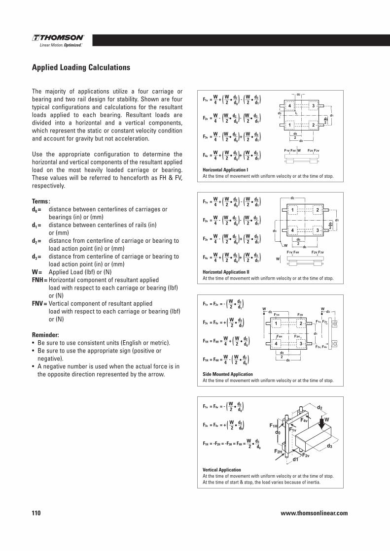
www.thomsonlinear.com110
Applied Loading Calculations
The majority of applications utilize a four carriage or bearing and two rail design for stability . Shown are four typical configurations and calculations for the resultant loads applied to each bearing . Resultant loads are divided into a horizontal and a vertical components, which represent the static or constant velocity condition and account for gravity but not acceleration .
Use the appropriate configuration to determine the hori zontal and vertical components of the resultant applied load on the most heavily loaded carriage or bearing . These values will be referred to henceforth as FH & FV, respectively .
Terms :d0 = distance between centerlines of carriages or
bearings (in) or (mm)d1 = distance between centerlines of rails (in)
or (mm) d2 = distance from centerline of carriage or bearing to
load action point (in) or (mm)d3 = distance from centerline of carriage or bearing to
load action point (in) or (mm)W = Applied Load (lbf) or (N)FNH = Horizontal component of resultant applied
load with respect to each carriage or bearing (lbf) or (N)
FNV = Vertical component of resultant applied load with respect to each carriage or bearing (lbf) or (N)
Reminder: • Be sure to use consistent units (English or metric) .• Be sure to use the appropriate sign (positive or
negative) .• A negative number is used when the actual force is in
the opposite direction represented by the arrow .
F1v = W + W • d2 - W
• d3
4 2 d0 2 d1
F2v = W - W • d2 - W
• d3
4 2 d0 2 d1
F3v = W - W • d2 + W
• d3
4 2 d0 2 d1
F4v = W + W • d2 + W
• d3
4 2 d0 2 d1
Horizontal Application IAt the time of movement with uniform velocity or at the time of stop .
(
(
(
(
(
(
(
(
(
(
(
(
(
(
(
(
F1v = W + W • d2 - W
• d3
4 2 d0 2 d1
F2v = W - W • d2 - W
• d3
4 2 d0 2 d1
F3v = W - W • d2 + W
• d3
4 2 d0 2 d1
F4v = W + W • d2 + W
• d3
4 2 d0 2 d1
Horizontal Application IIAt the time of movement with uniform velocity or at the time of stop .
(
(
(
(
(
(
(
(
(
(
(
(
(
(
(
(F1v = F2v = - W
• d3
2 d1
F3v = F4v = + W • d3
2 d1
F1H = F4H = W + W • d2
4 2 d0
F1H = F4H = W - W • d2
4 2 d0
Side Mounted Application At the time of movement with uniform velocity or at the time of stop .
(
(
(
(
(
(
(
(
d1F2v
F2H
d0
d2
F1vF1H
F4v
d3
W
Vertical ApplicationAt the time of movement with uniform velocity or at the time of stop .At the time of start & stop, the load varies because of inertia .
F1v = F4v = - W • d2
2 d0
F3v = F4v = + W • d2
2 d0
F1H = -F2H = -F3H = F4H = W • d3
2 d0
(
(
(
(
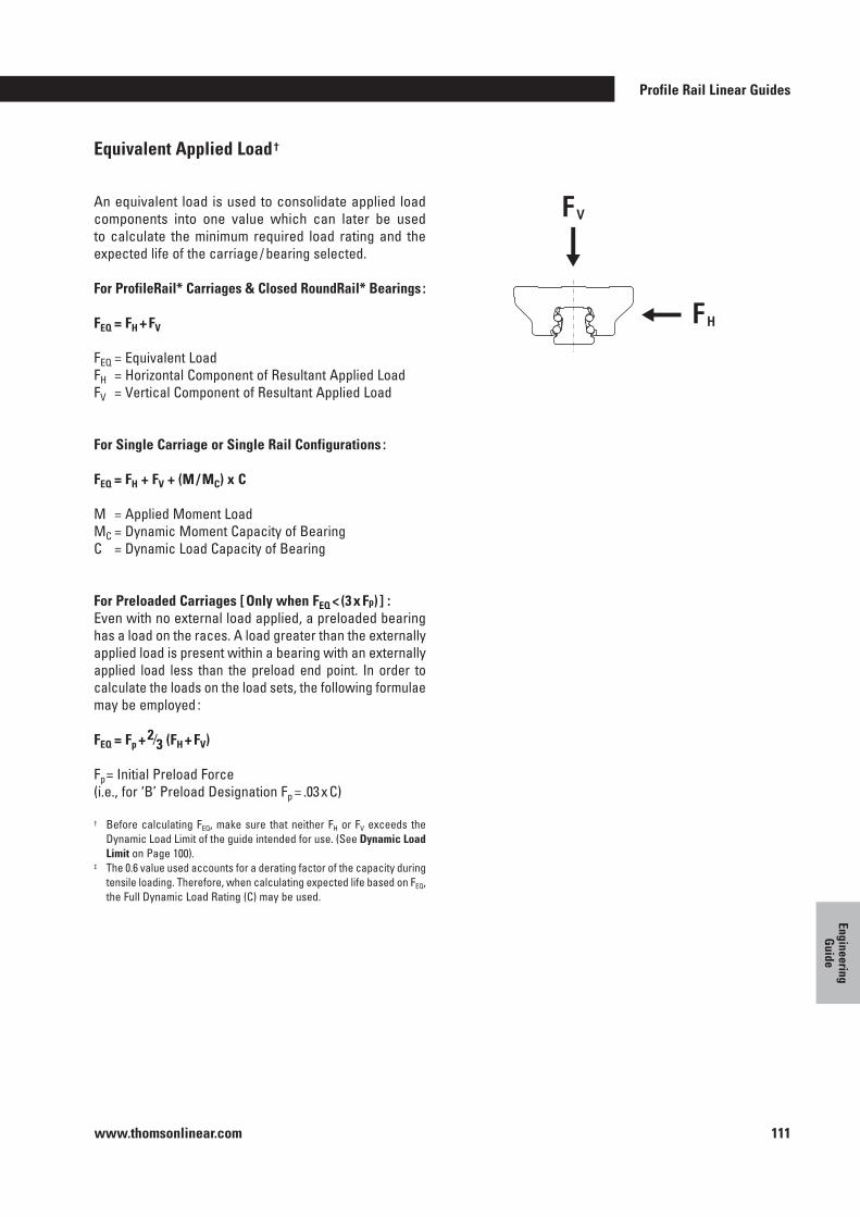
Profile Rail Linear Guides
www.thomsonlinear.com 111
Engineering G
uide
Equivalent Applied Load †
An equivalent load is used to consolidate applied load components into one value which can later be used to calculate the minimum required load rating and the expected life of the carriage / bearing selected .
For ProfileRail* Carriages & Closed RoundRail* Bearings :
FEQ = FH + FV
FEQ = Equivalent LoadFH = Horizontal Component of Resultant Applied LoadFV = Vertical Component of Resultant Applied Load
For Single Carriage or Single Rail Configurations :
FEQ = FH + FV + (M / MC) x C
M = Applied Moment LoadMC = Dynamic Moment Capacity of BearingC = Dynamic Load Capacity of Bearing
For Preloaded Carriages [ Only when FEQ < (3 x Fp) ] :Even with no external load applied, a preloaded bearing has a load on the races . A load greater than the externally applied load is present within a bearing with an externally applied load less than the preload end point . In order to calculate the loads on the load sets, the following formulae may be employed :
FEQ = Fp + 2⁄3 (FH + FV)
Fp = Initial Preload Force(i .e ., for ‘B’ Preload Designation Fp = .03 x C)
† Before calculating FEQ, make sure that neither FH or FV exceeds the Dynamic Load Limit of the guide intended for use . (See Dynamic Load Limit on Page 100) .
‡ The 0 .6 value used accounts for a derating factor of the capacity during tensile loading . Therefore, when calculating expected life based on FEQ, the Full Dynamic Load Rating (C) may be used .
FV
FH
www.thomsonlinear.com112
In applications with loads of varying magnitude, a mean dynamic load should be calculated .
Where :FEQ1…FEQn = equivalent dynamic load for distances d1
through dnD = total distance of stroke = d1+d2…+dmP = 3 (linear guides w/Ball Type Rolling Elements)
10/3 (linear guides w/Roller Type Rolling Elements)
Load Ratings for Rolling Element Guides
Dynamic Load Rating, C, and Travel LifeThe dynamic load rating, C, is the load at which when applied will yield the rated travel life . The rated travel life, Lr, for most linear guides is 100 km for metric products and 4 million inches for inch products (the rated travel life is listed on the page with the dynamic load rating) . For a given applied load, P, the dynamic load rating and rated travel life are used to calculate the travel life using the following load / life equation :
L = (C/FEQ)n x L r
Where :L = calculated travel lifeC = dynamic load ratingFEQ = equivalent applied loadn = 3 for ball guides, 10/3 for roller guidesL r = rated travel life
Some manufacturers dynamic load ratings are based upon a 50 km life . To compare dynamic load ratings for guides with a 50 km rated life with a 100 km life, divide the 50 km dynamic load rating by 1 .26 .
C 100 km = C 50 km / 1 .26
Some types of linear guides do not have the same dynamic load rating in all directions . The dynamic load rating for orthogonal load directions is shown as a percentage of C . It is not necessary to use this percentage of C in the load / life equation provided that the Equivalent Applied Load Section has been adhered to, because the calculations for equivalent applied load already account for it .
Mean Dynamic Load
Profile Rail Linear Guides
www.thomsonlinear.com 113
Engineering G
uide
Calculating the Minimum Required Dynamic Load Rating, Cmin
The load / life equation above can be rewritten to calculate the minimum required dynamic load rating which should be selected for a given applied load and minimum required travel life :
Cmin = P(L m / L r)1 / n
Where :Cmin = minimum required dynamic load ratingP = applied loadLm = minimum required travel lifeLr = rated travel lifen = 3 for ball guides, 10/3 for roller guides
Note : Check that the applied load, P does not exceed the dynamic load limit .
Dynamic Load LimitThe dynamic load limit, is the maximum load which should be applied to the carriage / pillowblock . In some cases, the dynamic load capacity equals the dynamic load rating . In others, a limit shown as a percentage of the dynamic load rating is the maximum load which should be applied . A dynamic load limit less than the dynamic load rating does not derate the life of the guide .
Static CapacitiesThe static capacities are the maximum loads that should be applied to the bearing while there is no relative motion between the rolling elements and the raceways . The value C0 is the static load capacity for a radial load acting orthogonal to the axis of travel . The values MOL and MOQ
are the static roll, pitch, and yaw moment capacities .
It is important to analyze the application so that shock loads do not exceed these capacities . Exceeding these capacities may permanently deform the rolling elements and raceways . This type of damage will be realized by an increase in friction, noise, and vibration, as well as by an increase in clearance between the carriage and the rail .
For systems experiencing repetitive shock loading less than the static load capacities, the bearing life should be determined by means of fatigue calculations .
www.thomsonlinear.com114
PreloadA preloaded bearing has a condition of interference between the races of the rails, the rolling elements, and the races of the carriage .
Preloading decreases the deflection due to external loads . This occurs because the contact reaction has already developed, eliminating much of the initial non-linear deflection associated with rolling elements .
The rolling element reactions within a preloaded bearing may be considered as having two components . One com ponent acts in the direction of external load, and one component acts in the opposing direction in order to maintain static equilibrium . These components are referred to as load sets . As external load is applied, one load set increases in load, as the opposite load set decreases in load . At some point, the load on the decreasing load set becomes zero . This point, at which the preload is relieved, is called the preload end point . Preload end typically occurs when the external load is approximately three times the preload .
Preload end point :
Fext = 3Fp
where:Fext = externally applied loadFp = preload
By definition, a preloaded bearing, loaded beyond the pre-load endpoint, has the same deflection characteristics of an unpreloaded bearing externally loaded to that per-centage of its dynamic load capacity . A preload level is assigned as a percentage of the dynamic load capacity of the bearing .
Preloading & Linear Guide Deflection Deflection Curves
Curves are available for Thomson 500 Series at:www .thomsonlinear .com .
Preload Clearance .03C .08 - .13C
Conditions1 . weak impact2 . 2 rails in pair3 . low accuracy4 . small resistance
1 . cantilever2 . single rail3 . light load4 . high accuracy
1 . strong impact2 . strong vibration3 . heavy machining
Applications
1 . welding machine2 . chopping machine3 . feeding mechanism4 . tool change mechanism5 . ordinary XY table
1 . NC lathe2 . EDM3 . precise XY table4 . ordinary Z-axis5 . industrial robot6 . PCB punching
1 . machining centre2 . NC lathe and milling machine3 . feeding axis of grinder4 . tool feeding axis
Example Applications
Profile Rail Linear Guides
www.thomsonlinear.com 115
Engineering G
uide
Actuation Force
The force required to actuate a linear guide (FA) has four basic components :
1 . Frictional resistance (Ff)2 . Intrinsic resistance (Dint)3 . Inertia of the moving components (Finertia)4 . Viscose drag of the lubrication (Dl)
FA = Ff + Dint + Finertia + Dl
Frictional Resistance
Rolling Element GuidesFriction occurs in rolling element guides as a result of slipping of the rolling elements on the raceways . The frictional resistance can be calculated by means of the following equation :
Ff = µ x Fi
Where :µ = coefficient of friction (dependent upon type of guide
type, rolling element type and load)Fi = force internal to the linear guide
The following table lists the coefficient of friction for different types of guides :
Profile Rail Ball Type Roller Type 0 .002 - 0 .003 0 .001 - 0 .002
The value for the coefficient of friction is a function of the applied load . The coefficient of friction increases as load is applied . This is due to the increased contact area between the rolling elements and races .
The force internal to the linear guide is equal to the external force (Fext) applied to the linear guide in non-preloaded guides, and preloaded guides loaded beyond 3 times the preload value (Fp) .
Fi = Fext
For preloaded guides loaded below a level of 3 times the preload value (Fp), the internal force can be approximated with the following equation :
Fi = 2Fp + 1/3 Fext
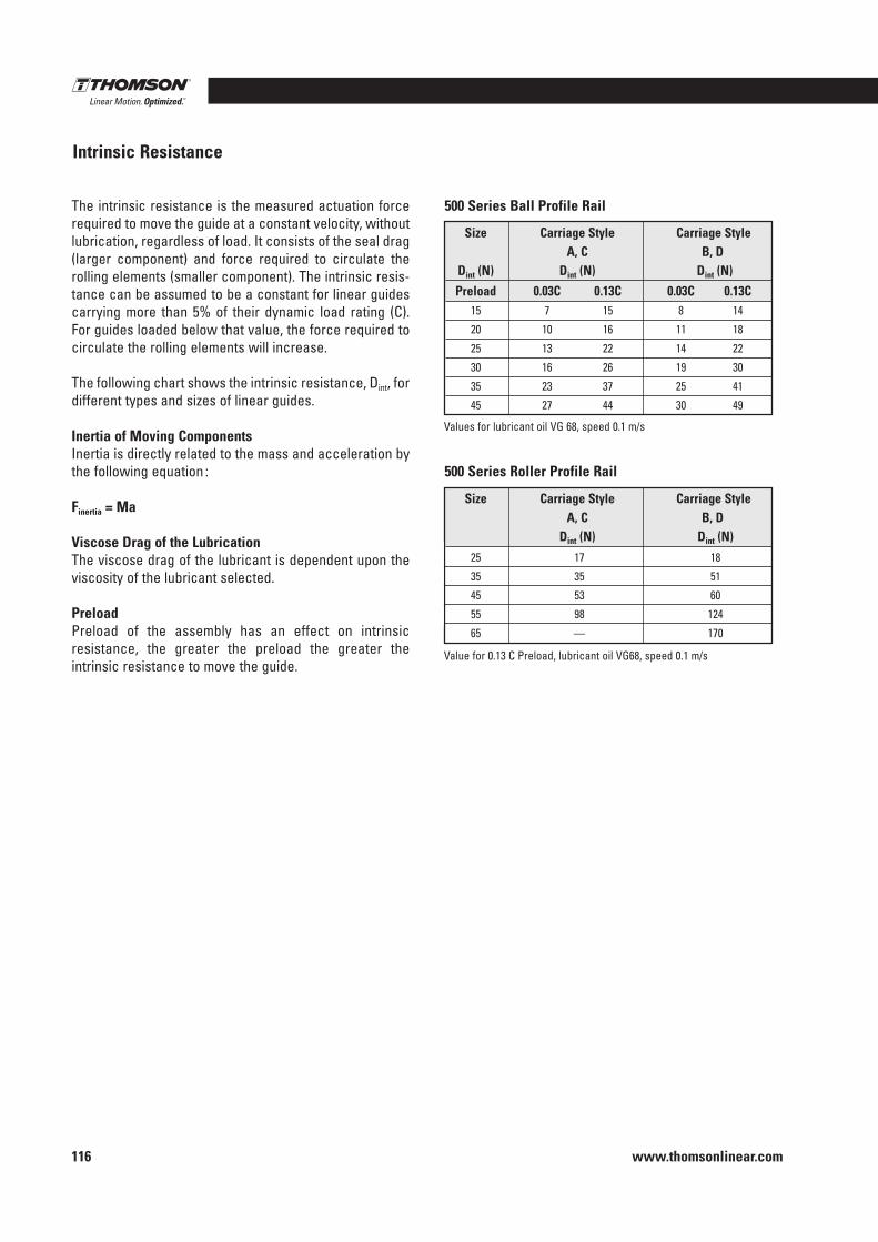
www.thomsonlinear.com116
The intrinsic resistance is the measured actuation force required to move the guide at a constant velocity, without lubrication, regardless of load . It consists of the seal drag (larger component) and force required to circulate the rolling elements (smaller component) . The intrinsic resis-tance can be assumed to be a constant for linear guides carrying more than 5% of their dynamic load rating (C) . For guides loaded below that value, the force required to circulate the rolling elements will increase .
The following chart shows the intrinsic resistance, Dint, for different types and sizes of linear guides .
Inertia of Moving ComponentsInertia is directly related to the mass and acceleration by the following equation :
Finertia = Ma
Viscose Drag of the LubricationThe viscose drag of the lubricant is dependent upon the viscosity of the lubricant selected .
PreloadPreload of the assembly has an effect on intrinsic resistance, the greater the preload the greater the intrinsic resistance to move the guide .
Intrinsic Resistance
500 Series Ball Profile Rail
500 Series Roller Profile Rail
Values for lubricant oil VG 68, speed 0 .1 m/s
Size Carriage Style Carriage Style A, C B, D Dint (N) Dint (N) Dint (N)
Preload 0 .03C 0 .13C 0 .03C 0 .13C 15 7 15 8 14
20 10 16 11 18
25 13 22 14 22
30 16 26 19 30
35 23 37 25 41
45 27 44 30 49
Value for 0 .13 C Preload, lubricant oil VG68, speed 0 .1 m/s
Size Carriage Style Carriage Style A, C B, D Dint (N) Dint (N)
25 17 18
35 35 51
45 53 60
55 98 124
65 — 170
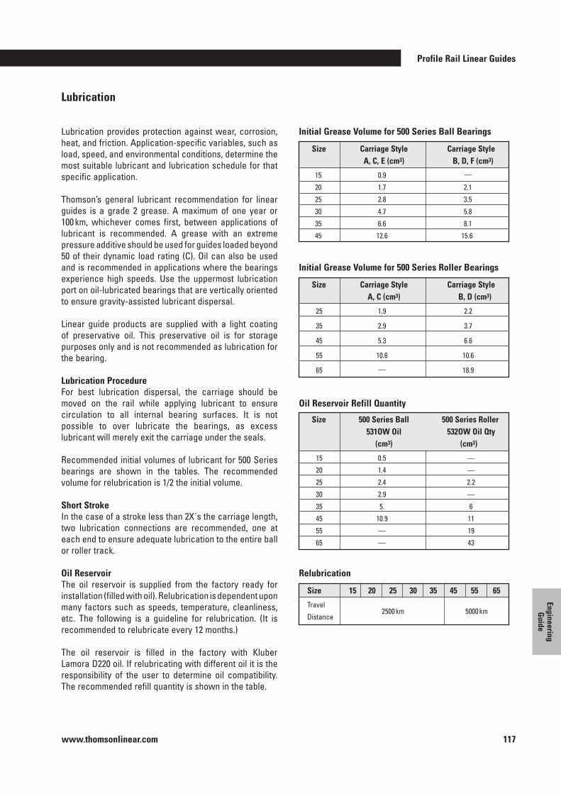
Profile Rail Linear Guides
www.thomsonlinear.com 117
Engineering G
uide
Lubrication
Lubrication provides protection against wear, corrosion, heat, and friction . Application-specific variables, such as load, speed, and environmental conditions, determine the most suitable lubricant and lubrication schedule for that specific application .
Thomson’s general lubricant recommendation for linear guides is a grade 2 grease . A maximum of one year or 100 km, whichever comes first, between applications of lubricant is recommended . A grease with an extreme pressure additive should be used for guides loaded beyond 50 of their dynamic load rating (C) . Oil can also be used and is recommended in applications where the bearings experience high speeds . Use the uppermost lubrication port on oil-lubricated bearings that are vertically oriented to ensure gravity-assisted lubricant dispersal .
Linear guide products are supplied with a light coating of preservative oil . This preservative oil is for storage purposes only and is not recommended as lubrication for the bearing .
Lubrication ProcedureFor best lubrication dispersal, the carriage should be moved on the rail while applying lubricant to ensure circulation to all internal bearing surfaces . It is not possible to over lubricate the bearings, as excess lubricant will merely exit the carriage under the seals .
Recommended initial volumes of lubricant for 500 Series bearings are shown in the tables . The recommended volume for relubrication is 1/2 the initial volume .
Short StrokeIn the case of a stroke less than 2X´s the carriage length, two lubrication connections are recommended, one at each end to ensure adequate lubrication to the entire ball or roller track .
Oil ReservoirThe oil reservoir is supplied from the factory ready for installation (filled with oil) . Relubrication is dependent upon many factors such as speeds, temperature, cleanliness, etc . The following is a guideline for relubrication . (It is recommended to relubricate every 12 months .)
The oil reservoir is filled in the factory with Kluber Lamora D220 oil . If relubricating with different oil it is the responsibility of the user to determine oil compatibility . The recommended refill quantity is shown in the table .
Initial Grease Volume for 500 Series Ball Bearings
Initial Grease Volume for 500 Series Roller Bearings
Oil Reservoir Refill Quantity
Relubrication
Size Carriage Style Carriage Style A, C, E (cm3) B, D, F (cm3)
15 0 .9 —
20 1 .7 2 .1
25 2 .8 3 .5
30 4 .7 5 .8
35 6 .6 8 .1
45 12 .6 15 .6
Size Carriage Style Carriage Style A, C (cm3) B, D (cm3)
25 1 .9 2 .2
35 2 .9 3 .7
45 5 .3 6 .6
55 10 .6 10 .6
65 — 18 .9
Size 500 Series Ball 500 Series Roller 531OW Oil 532OW Oil Qty (cm3) (cm3)
15 0 .5 —
20 1 .4 —
25 2 .4 2 .2
30 2 .9 —
35 5 . 6
45 10 .9 11
55 — 19
65 — 43
Size 15 20 25 30 35 45 55 65
Travel
Distance 2500 km 5000 km
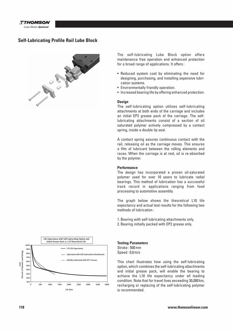
www.thomsonlinear.com118
The self-lubricating Lube Block option offers maintenance free operation and enhanced protection for a broad range of applications . It offers :
• Reduced system cost by eliminating the need for designing, purchasing, and installing expensive lubri-cation systems .
• Environmentally friendly operation .• Increased bearing life by offering enhanced protection .
Design The self-lubricating option utilizes self-lubricating attachments at both ends of the carriage and includes an initial EP2 grease pack of the carriage . The self-lubricating attachments consist of a section of oil saturated polymer actively compressed by a contact spring, inside a double lip seal .
A contact spring assures continuous contact with the rail, releasing oil as the carriage moves . This ensures a film of lubricant between the rolling elements and races . When the carriage is at rest, oil is re-absorbed by the polymer .
PerformanceThe design has incorporated a proven oil-saturated polymer used for over 10 years to lubricate radial bearings . This method of lubrication has a successful track record in applications ranging from food processing to automotive assembly .
The graph below shows the theoretical L10 life expectancy and actual test results for the following two methods of lubrication :
1 . Bearing with self-lubricating attachments only .2 . Bearing initially packed with EP2 grease only .
Testing ParametersStroke : 500 mmSpeed : 0,6 m/s
This chart illustrates how using the self-lubricating option, which combines the self-lubricating attachments and initial grease pack, will enable the bearing to achieve the L10 life expectancy under all loading condition . Note that for travel lives exceeding 30,000 km, recharging or replacing of the self-lubricating polymer is recommended .
Self-Lubricating Profile Rail Lube Block
10%
20%
30%
40%
50%
60%
70%
80%
90%
100%
0 500 1000
L10 Life Expectancy
1500 2000 2500 3000 3500 4000
Life (km)
Load
(P
erce
nt o
f Dyn
amic
Loa
d Ra
ting
)
Initially Lubricated with EP-2 Grease
Lubricated with Self-Lubrication Attachments
Life Expectancy with Self-Lubricating Option and Initial Grease Pack vs. L10 Theoretical Life
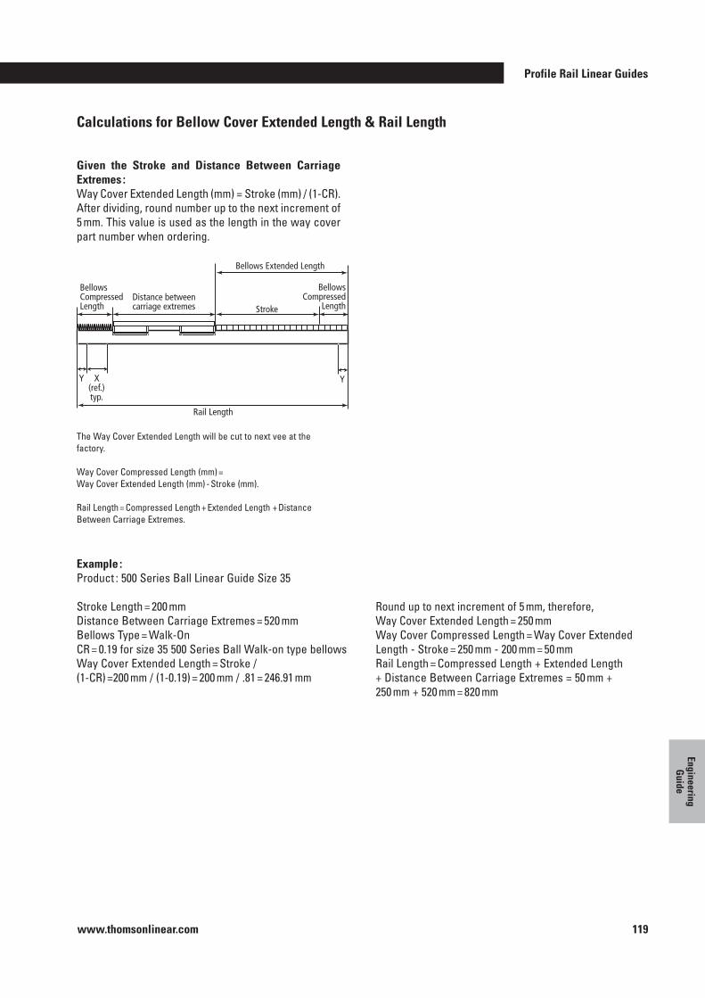
Profile Rail Linear Guides
www.thomsonlinear.com 119
Engineering G
uide
Calculations for Bellow Cover Extended Length & Rail Length
Example :Product : 500 Series Ball Linear Guide Size 35
Stroke Length = 200 mmDistance Between Carriage Extremes = 520 mmBellows Type = Walk-OnCR = 0 .19 for size 35 500 Series Ball Walk-on type bellowsWay Cover Extended Length = Stroke / (1-CR) =200 mm / (1-0 .19) = 200 mm / .81 = 246 .91 mm
Round up to next increment of 5 mm, therefore, Way Cover Extended Length = 250 mmWay Cover Compressed Length = Way Cover Extended Length - Stroke = 250 mm - 200 mm = 50 mmRail Length = Compressed Length + Extended Length + Distance Between Carriage Extremes = 50 mm + 250 mm + 520 mm = 820 mm
Given the Stroke and Distance Between Carriage Extremes :Way Cover Extended Length (mm) = Stroke (mm) / (1-CR) . After dividing, round number up to the next increment of 5 mm . This value is used as the length in the way cover part number when ordering .
Bellows Compressed Length
Bellows Compressed
Length Distance between carriage extremes
Bellows Extended Length
Stroke
Rail Length
X (ref.) typ.
Y Y
The Way Cover Extended Length will be cut to next vee at the factory .
Way Cover Compressed Length (mm) = Way Cover Extended Length (mm) - Stroke (mm) .
Rail Length = Compressed Length + Extended Length + Distance Between Carriage Extremes .
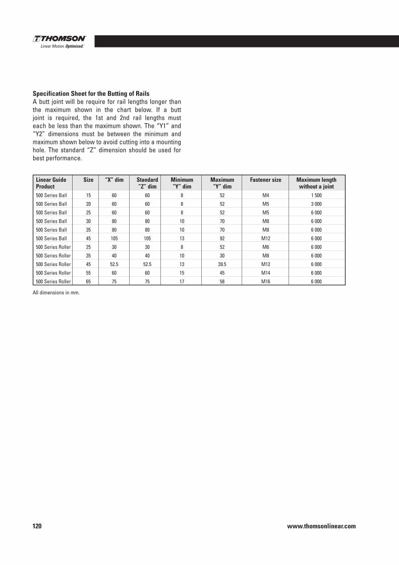
www.thomsonlinear.com120
Specification Sheet for the Butting of RailsA butt joint will be require for rail lengths longer than the maximum shown in the chart below . If a butt joint is required, the 1st and 2nd rail lengths must each be less than the maximum shown . The “Y1” and “Y2” dimensions must be between the minimum and maximum shown below to avoid cutting into a mounting hole . The standard “Z” dimension should be used for best performance .
Linear Guide Size “X” dim Standard Minimum Maximum Fastener size Maximum length Product “Z” dim “Y” dim “Y” dim without a joint
500 Series Ball 15 60 60 8 52 M4 1 500
500 Series Ball 20 60 60 8 52 M5 3 000
500 Series Ball 25 60 60 8 52 M5 6 000
500 Series Ball 30 80 80 10 70 M8 6 000
500 Series Ball 35 80 80 10 70 M8 6 000
500 Series Ball 45 105 105 13 92 M12 6 000
500 Series Roller 25 30 30 8 52 M6 6 000
500 Series Roller 35 40 40 10 30 M8 6 000
500 Series Roller 45 52 .5 52 .5 13 39 .5 M12 6 000
500 Series Roller 55 60 60 15 45 M14 6 000
500 Series Roller 65 75 75 17 58 M16 6 000
All dimensions in mm .
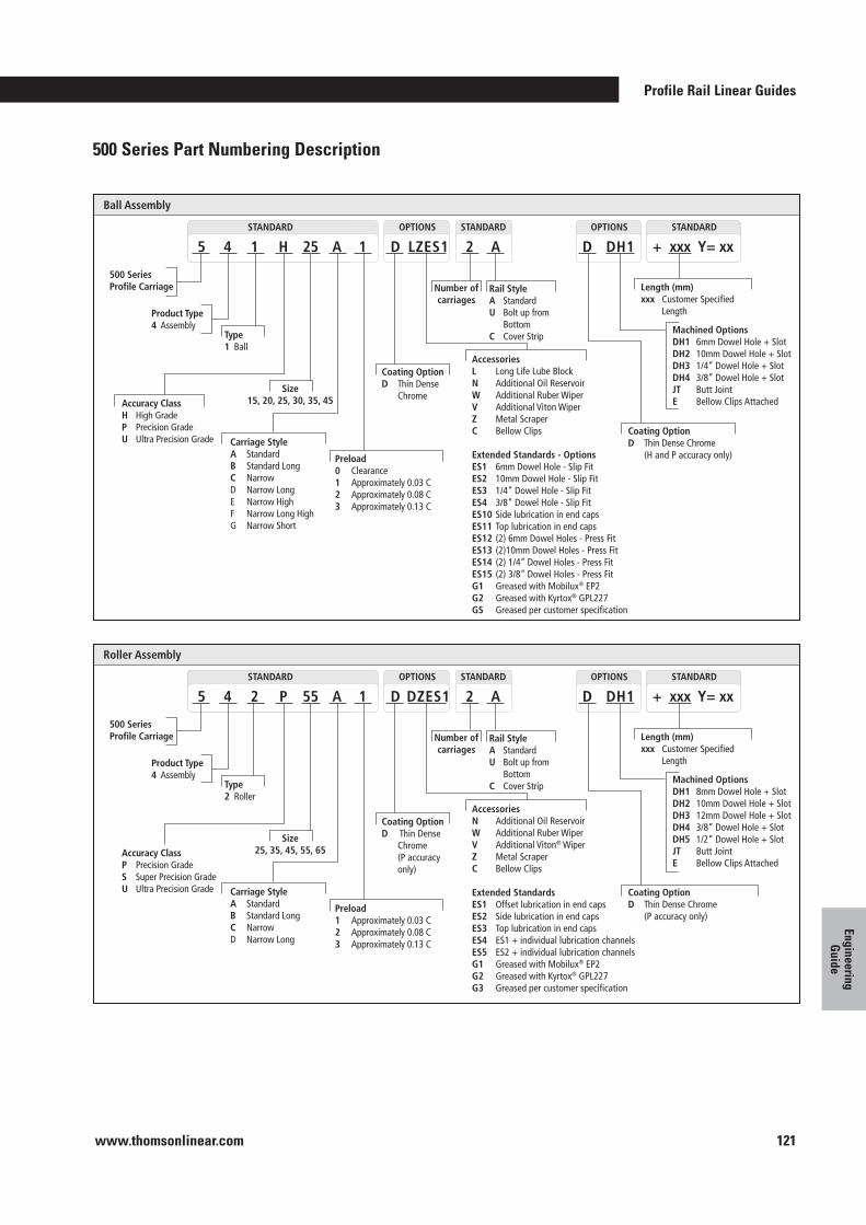
Profile Rail Linear Guides
www.thomsonlinear.com 121
Engineering G
uide
Standard STANDARD OPTIONS
Roller Assembly
500 Series Profile Carriage
Product Type4 Assembly
5 4 2 P 55 A D DZES1
Length (mm)xxx Customer Specified Length
AccessoriesN Additional Oil ReservoirW Additional Ruber WiperV Additional Viton® WiperZ Metal ScraperC Bellow Clips
Extended StandardsES1 Offset lubrication in end capsES2 Side lubrication in end capsES3 Top lubrication in end capsES4 ES1 + individual lubrication channelsES5 ES2 + individual lubrication channelsG1 Greased with Mobilux® EP2G2 Greased with Kyrtox® GPL227G3 Greased per customer specification
Accuracy Class P Precision GradeS Super Precision GradeU Ultra Precision Grade
Size25, 35, 45, 55, 65
Carriage Style A StandardB Standard LongC NarrowD Narrow Long
Coating Option D Thin Dense Chrome (P accuracy only)
Type2 Roller
Number ofcarriages
1
Preload 1 Approximately 0.03 C2 Approximately 0.08 C3 Approximately 0.13 C
Machined OptionsDH1 8mm Dowel Hole + SlotDH2 10mm Dowel Hole + SlotDH3 12mm Dowel Hole + SlotDH4 3/8” Dowel Hole + SlotDH5 1/2” Dowel Hole + SlotJT Butt JointE Bellow Clips Attached
STANDARD STANDARDOPTIONS
2 A D DH1 + xxx Y= xx
Rail Style A StandardU Bolt up from BottomC Cover Strip
Coating Option D Thin Dense Chrome (P accuracy only)
Standard STANDARD OPTIONS
Ball Assembly
500 Series Profile Carriage
Product Type4 Assembly
5 4 1 H 25 A D LZES1
Length (mm)xxx Customer Specified Length
AccessoriesL Long Life Lube BlockN Additional Oil ReservoirW Additional Ruber WiperV Additional Viton WiperZ Metal ScraperC Bellow Clips
Extended Standards - OptionsES1 6mm Dowel Hole - Slip FitES2 10mm Dowel Hole - Slip FitES3 1/4” Dowel Hole - Slip FitES4 3/8” Dowel Hole - Slip FitES10 Side lubrication in end capsES11 Top lubrication in end capsES12 (2) 6mm Dowel Holes - Press FitES13 (2)10mm Dowel Holes - Press FitES14 (2) 1/4” Dowel Holes - Press FitES15 (2) 3/8” Dowel Holes - Press FitG1 Greased with Mobilux® EP2G2 Greased with Kyrtox® GPL227GS Greased per customer specification
Accuracy Class H High GradeP Precision GradeU Ultra Precision Grade
Size15, 20, 25, 30, 35, 45
Carriage Style A StandardB Standard LongC NarrowD Narrow LongE Narrow HighF Narrow Long HighG Narrow Short
Coating Option D Thin Dense Chrome
Type1 Ball
Number ofcarriages
1
Preload 0 Clearance1 Approximately 0.03 C2 Approximately 0.08 C3 Approximately 0.13 C
Machined OptionsDH1 6mm Dowel Hole + SlotDH2 10mm Dowel Hole + SlotDH3 1/4” Dowel Hole + SlotDH4 3/8” Dowel Hole + SlotJT Butt JointE Bellow Clips Attached
STANDARD STANDARDOPTIONS
2 A D DH1 + xxx Y= xx
Rail Style A StandardU Bolt up from BottomC Cover Strip
Coating Option D Thin Dense Chrome (H and P accuracy only)
500 Series Part Numbering Description
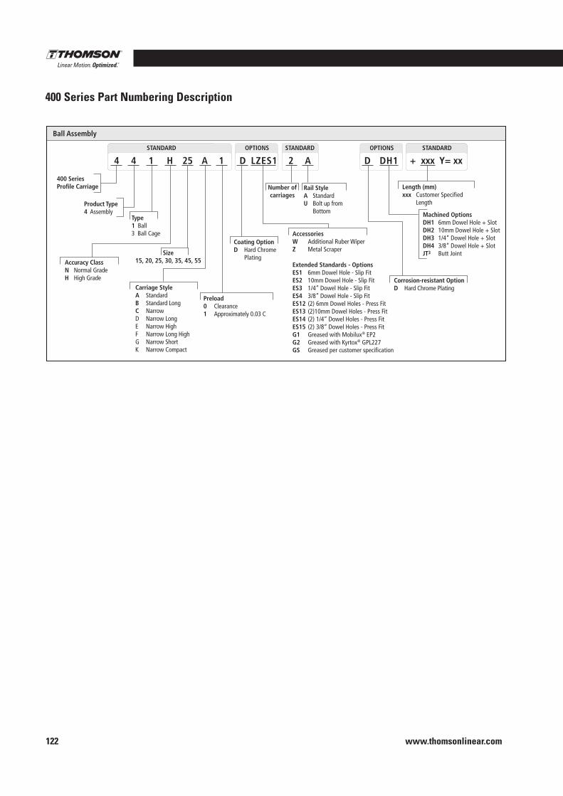
www.thomsonlinear.com122
Standard STANDARD OPTIONS
Ball Assembly
400 Series Profile Carriage
Product Type4 Assembly
4 4 1 H 25 A D LZES1
Length (mm)xxx Customer Specified Length
AccessoriesW Additional Ruber WiperZ Metal Scraper
Extended Standards - OptionsES1 6mm Dowel Hole - Slip FitES2 10mm Dowel Hole - Slip FitES3 1/4” Dowel Hole - Slip FitES4 3/8” Dowel Hole - Slip FitES12 (2) 6mm Dowel Holes - Press FitES13 (2)10mm Dowel Holes - Press FitES14 (2) 1/4” Dowel Holes - Press FitES15 (2) 3/8” Dowel Holes - Press FitG1 Greased with Mobilux® EP2G2 Greased with Kyrtox® GPL227GS Greased per customer specification
Accuracy Class N Normal GradeH High Grade
Size15, 20, 25, 30, 35, 45, 55
Carriage Style A StandardB Standard LongC NarrowD Narrow LongE Narrow HighF Narrow Long HighG Narrow ShortK Narrow Compact
Coating Option D Hard Chrome Plating
Type1 Ball3 Ball Cage
Number ofcarriages
1
Preload 0 Clearance1 Approximately 0.03 C
Machined OptionsDH1 6mm Dowel Hole + SlotDH2 10mm Dowel Hole + SlotDH3 1/4” Dowel Hole + SlotDH4 3/8” Dowel Hole + SlotJT3 Butt Joint
STANDARD STANDARDOPTIONS
2 A D DH1 + xxx Y= xx
Rail Style A StandardU Bolt up from Bottom
Corrosion-resistant Option D Hard Chrome Plating
400 Series Part Numbering Description
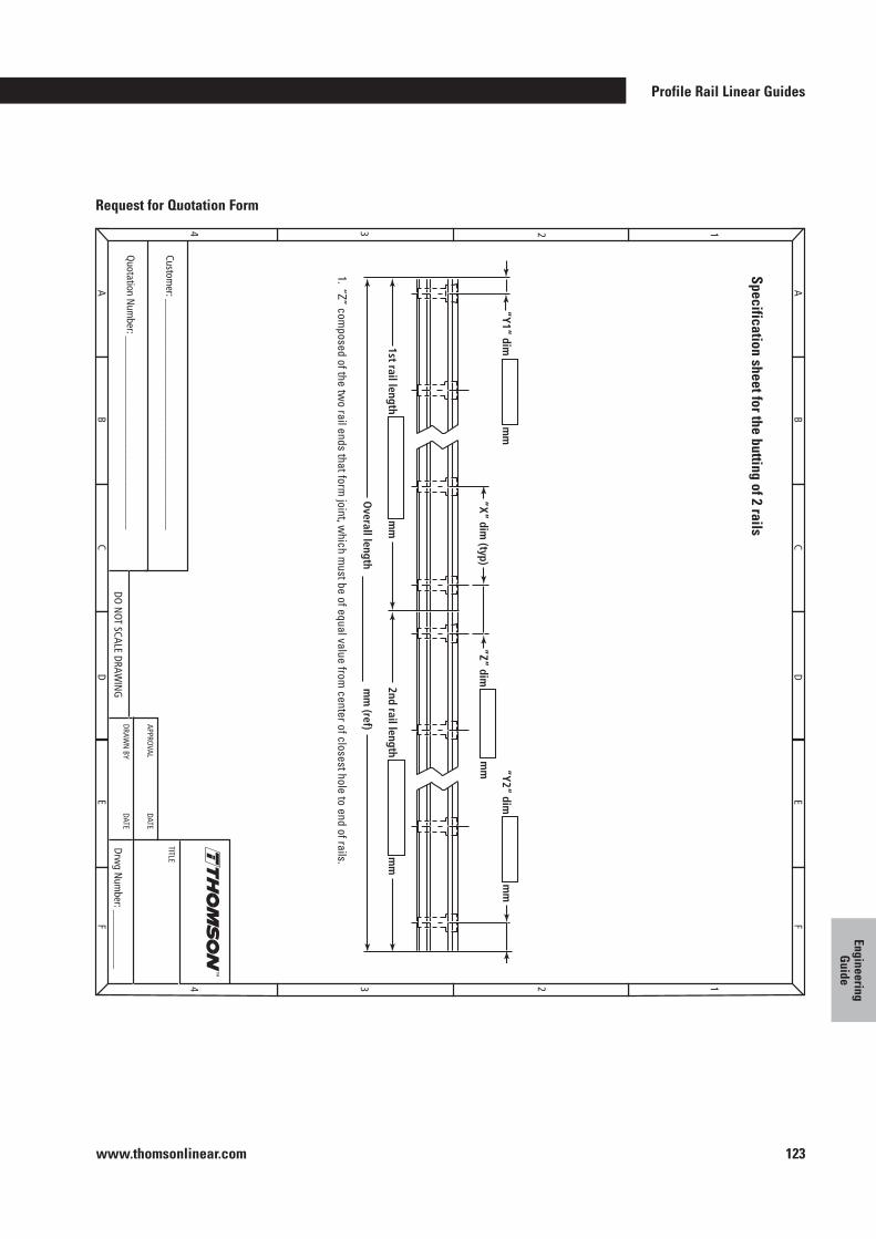
Profile Rail Linear Guides
www.thomsonlinear.com 123
Engineering G
uide
Request for Quotation Form
1
AB
CD
EF
A
Quotation N
umber: ____________________________________
Customer: ___________________________________________
DO N
OT SCALE DRAWIN
G
FAX A
COPY O
F THIS FO
RM TO
SALES EN
GIN
EERING
DEPA
RTMEN
T, FAX: +
44 1271 334 501
Drwg N
umber: ___________
APPROVAL
DATE
TITLE
DRAWN
BY DATE
BC
DE
F
234
1234
“Y1” dim
“Y2” dim
mm
mm
2nd rail length
mm
(ref) O
verall length
mm
1st rail length
“Z” dim
mm
“X” dim
(typ)
mm
1 . “Z” composed of the tw
o rail ends that form joint, w
hich must be of equal value from
center of closest hole to end of rails .
Specification sheet for the butting of 2 rails
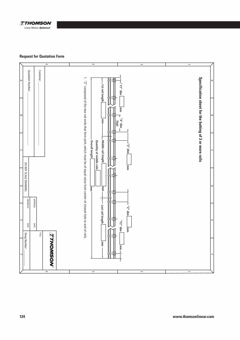
www.thomsonlinear.com124
Request for Quotation Form1
AB
CD
EF
A
Quotation N
umber: ____________________________________
Customer: ___________________________________________
DO N
OT SCALE DRAWIN
G
FAX A
COPY O
F THIS FO
RM TO
SALES EN
GIN
EERING
DEPA
RTMEN
T, FAX: +
44 1271 334 501
Drwg N
umber: ___________
APPROVAL
DATE
TITLE
DRAWN
BY DATE
BC
DE
F
234
1234
Specification sheet for the butting of 3 or more rails
1 . “Z” composed of the tw
o rail ends that form joint, w
hich must be of equal value from
center of closest hole to end of rails .
“ Y1” dim
“Y2” dim
Last rail length
mm
mm
“Z” dim
mm
mm
Middle rail length
Quantity of m
iddle rails
Overall length
mm
1st rail length
“X” dim
(typ) m
m
“Z” dim
mm
mm
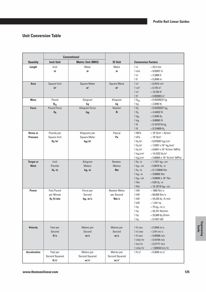
Profile Rail Linear Guides
www.thomsonlinear.com 125
Engineering G
uide
Conventional
Quantity Inch Unit Metric Unit (MKS) SI Unit Conversion Factors Length Inch Meter Metre 1 in = 25 .4 mm in m m 1 mm = 0 .03937 in 1 m = 3 .2808 ft 1 ft = 0 .3048 m
Area Square Inch Square Meter Square Metre 1 in2 = 6 .4516 cm2
in2 m2 m2 1 cm2 = 0 .155 in2
1 m2 = 10 .764 ft2
1 ft2 = 0 .092903 m2
Mass Pound Kilogram Kilogram 1 lbm = 0 .45359237 kg lbm kg kg 1 kg = 2 .2046 lb Force Pound Force Kilogram Force Newton 1 lbf = 0 .45359237 kgf
lbf kgf N 1 lbf = 4 .44822 N 1 kgf = 2 .2046 lbf
1 kgf = 9 .80665 N 1 N = 0 .1019716 kgf 1 N = 0 .224809 lbf
Stress or Pounds per Kilograms per Pascal 1 MPa = 106 N/m2 = N/mm2
Pressure Square Inch Square Meter Pa 1 kPa = 103 N/m2
lbf / in2 kgf / m
2 1 lbf /in2 = 0 .070307 kgf /cm2
1 lbf /in2 = 7 .0307 x 10-4 kgf /mm2
1 lbf /in2 = 6 .8947 x 10-3 N /mm2 (MPa)
1 kgf /cm2 = 14 .2233 lbf /in2
1 kgf /cm2 = 9 .80665 x 10-2 N /mm2 (MPa) Torque or Inch Kilogram Newton- 1 lbf - in = 1 .1521 kgf - cm Work Pounds Meters Metres 1 kgf - cm = 0 .8679 lbf - in lbf - in kgf - m Nm 1 lbf - in = 0 .1129848 Nm 1 kgf - m = 9 .80665 Nm 1 kgf - cm = 9 .80665 x 10-2 Nm 1 Nm = 8 .85 lbf - in 1 Nm = 10 .19716 kgf - cm Power Foot Pound Force per Newton Metre 1 kW = 1000 Nm / s per Minute Second per Second 1 kW = 60,000 Nm / s lbf -ft / min kgf - m / s Nm / s 1 kW = 44,220 lbf - ft / min 1 kW = 1 .341 hp 1 hp = 75 kgf - m / s 1 hp = 44,741 Nm/min 1 hp = 33,000 lbf-ft/min 1 hp = 0 .7457 kW Velocity Feet per Meters per Metres per 1 ft / sec = 0 .3048 m / s Second Second Second 1 in / sec = 2 .54 cm / s ft / s m / s m / s 1 ft / sec = 0 .00508 m/s 1 mile / hr = 0 .44704 m/s 1 km / hr = 0 .27777 m/s 1 mile / hr = 1 .609344 km / hr Acceleration Feet per Meters per Metres per 1 ft / s2 = 0 .3048 m / s2 Second Squared Second Squared Second Squared ft / s2 m / s2 m / s2
Unit Conversion Table
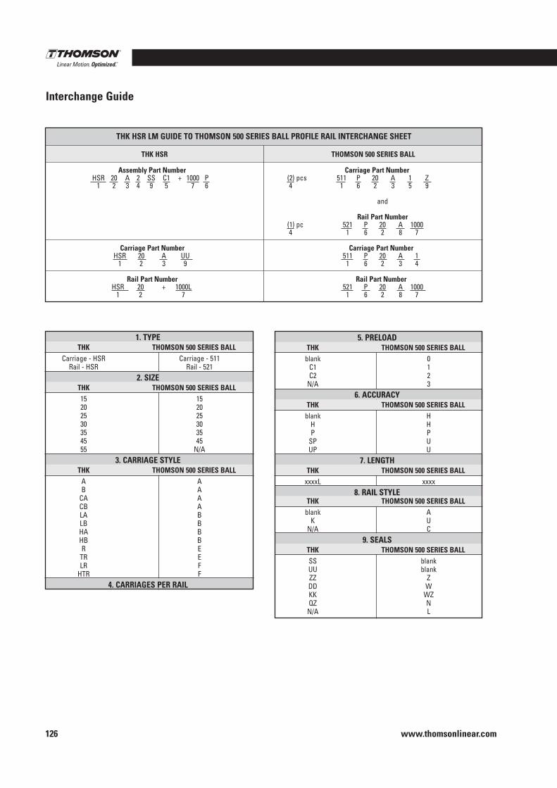
www.thomsonlinear.com126
Interchange Guide
5 . PRELOAD THK THOMSON 500 SERIES BALL blank 0 C1 1 C2 2 N/A 3 6 . ACCURACY THK THOMSON 500 SERIES BALL blank H H H P P SP U UP U 7 . LENGTH THK THOMSON 500 SERIES BALL xxxxL xxxx 8 . RAIL STYLE THK THOMSON 500 SERIES BALL blank A K U N/A C 9 . SEALS THK THOMSON 500 SERIES BALL SS blank UU blank ZZ Z DD W KK WZ QZ N N/A L
1 . TYPE THK THOMSON 500 SERIES BALL Carriage - HSR Carriage - 511 Rail - HSR Rail - 521 2 . SIZE THK THOMSON 500 SERIES BALL 15 15 20 20 25 25 30 30 35 35 45 45 55 N/A 3 . CARRIAGE STYLE THK THOMSON 500 SERIES BALL A A B A CA A CB A LA B LB B HA B HB B R E TR E LR F HTR F 4 . CARRIAGES PER RAIL
Assembly Part Number Carriage Part Number HSR 20 A 2 SS C1 + 1000 P (2) pcs 511 P 20 A 1 Z 1 2 3 4 9 5 7 6 4 1 6 2 3 5 9
and
Rail Part Number (1) pc 521 P 20 A 1000 4 1 6 2 8 7
Carriage Part Number Carriage Part Number HSR 20 A UU 511 P 20 A 1 1 2 3 9 1 6 2 3 4
Rail Part Number Rail Part Number HSR 20 + 1000L 521 P 20 A 1000 1 2 7 1 6 2 8 7
THK HSR LM GUIDE TO THOMSON 500 SERIES BALL PROFILE RAIL INTERCHANGE SHEET
THK HSR THOMSON 500 SERIES BALL
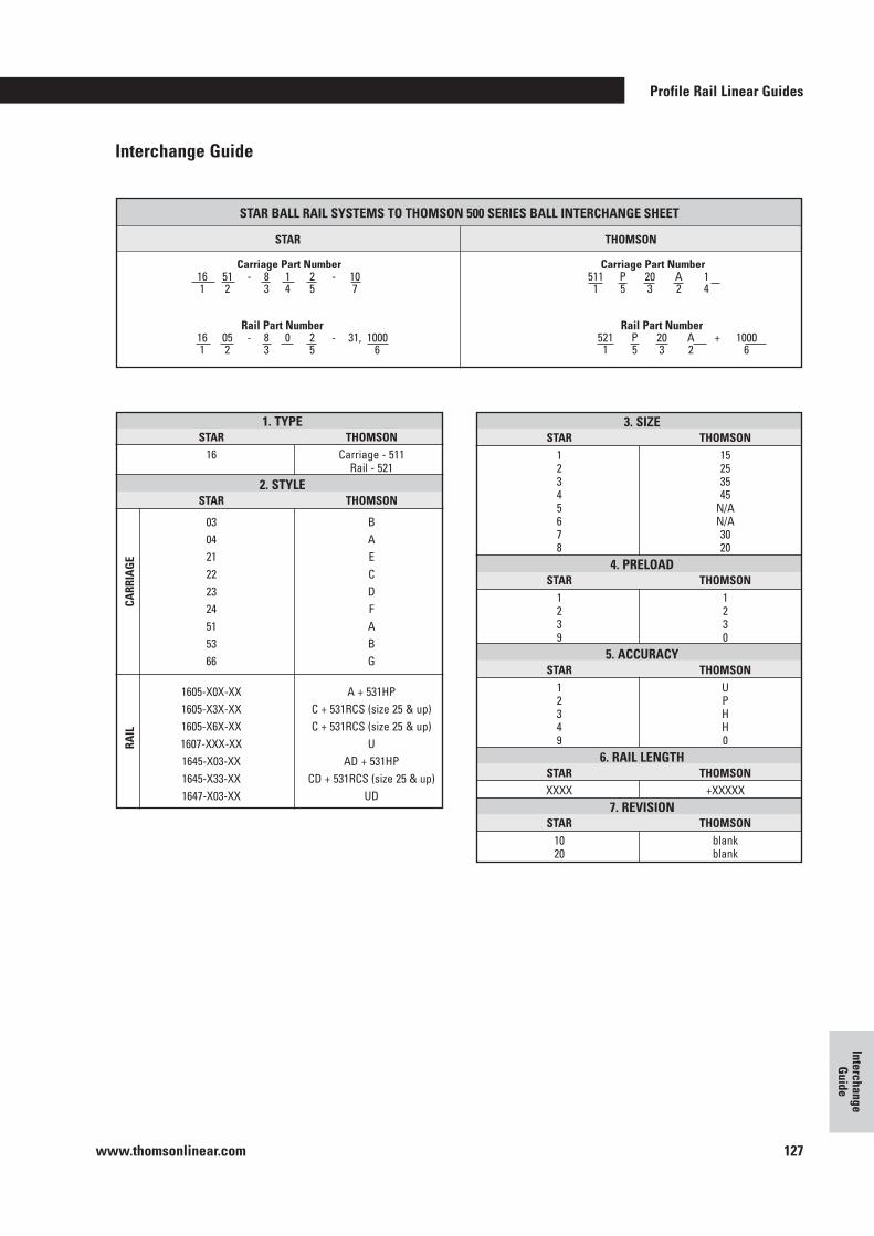
Profile Rail Linear Guides
www.thomsonlinear.com 127
Interchange G
uide
Interchange Guide
1 . TYPE STAR THOMSON 16 Carriage - 511 Rail - 521 2 . STYLE STAR THOMSON
03 B 04 A 21 E 22 C 23 D 24 F 51 A 53 B 66 G
1605-X0X-XX A + 531HP 1605-X3X-XX C + 531RCS (size 25 & up) 1605-X6X-XX C + 531RCS (size 25 & up) 1607-XXX-XX U 1645-X03-XX AD + 531HP 1645-X33-XX CD + 531RCS (size 25 & up) 1647-X03-XX UD
RAIL
CA
RRIA
GE
3 . SIZE STAR THOMSON 1 15 2 25 3 35 4 45 5 N/A 6 N/A 7 30 8 20 4 . PRELOAD STAR THOMSON 1 1 2 2 3 3 9 0 5 . ACCURACY STAR THOMSON 1 U 2 P 3 H 4 H 9 0 6 . RAIL LENGTH STAR THOMSON XXXX +XXXXX 7 . REVISION STAR THOMSON 10 blank 20 blank
Carriage Part Number Carriage Part Number 16 51 - 8 1 2 - 10 511 P 20 A 1 1 2 3 4 5 7 1 5 3 2 4
Rail Part Number Rail Part Number 16 05 - 8 0 2 - 31, 1000 521 P 20 A + 1000 1 2 3 5 6 1 5 3 2 6
STAR BALL RAIL SYSTEMS TO THOMSON 500 SERIES BALL INTERCHANGE SHEET
STAR THOMSON
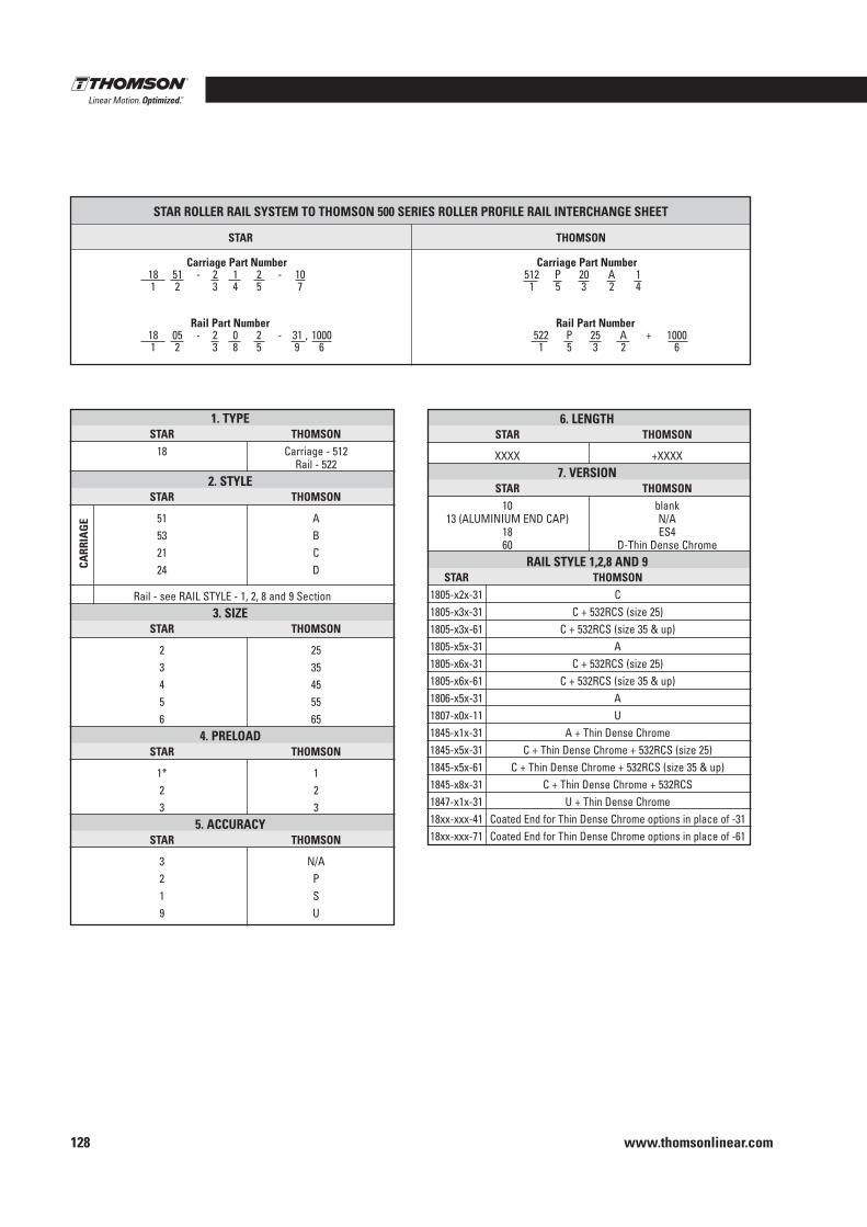
www.thomsonlinear.com128
1 . TYPE STAR THOMSON 18 Carriage - 512 Rail - 522 2 . STYLE STAR THOMSON
51 A 53 B 21 C 24 D
Rail - see RAIL STYLE - 1, 2, 8 and 9 Section 3 . SIZE STAR THOMSON
2 25 3 35 4 45 5 55 6 65 4 . PRELOAD STAR THOMSON
1* 1 2 2 3 3 5 . ACCURACY STAR THOMSON
3 N/A 2 P 1 S 9 U
CARR
IAG
E
6 . LENGTH STAR THOMSON
XXXX +XXXX 7 . VERSION STAR THOMSON 10 blank 13 (ALUMINIUM END CAP) N/A 18 ES4 60 D-Thin Dense Chrome RAIL STYLE 1,2,8 AND 9 STAR THOMSON 1805-x2x-31 C 1805-x3x-31 C + 532RCS (size 25) 1805-x3x-61 C + 532RCS (size 35 & up) 1805-x5x-31 A 1805-x6x-31 C + 532RCS (size 25) 1805-x6x-61 C + 532RCS (size 35 & up) 1806-x5x-31 A 1807-x0x-11 U 1845-x1x-31 A + Thin Dense Chrome 1845-x5x-31 C + Thin Dense Chrome + 532RCS (size 25) 1845-x5x-61 C + Thin Dense Chrome + 532RCS (size 35 & up) 1845-x8x-31 C + Thin Dense Chrome + 532RCS 1847-x1x-31 U + Thin Dense Chrome 18xx-xxx-41 Coated End for Thin Dense Chrome options in place of -31 18xx-xxx-71 Coated End for Thin Dense Chrome options in place of -61
STAR ROLLER RAIL SYSTEM TO THOMSON 500 SERIES ROLLER PROFILE RAIL INTERCHANGE SHEET
STAR THOMSON
Carriage Part Number Carriage Part Number 18 51 - 2 1 2 - 10 512 P 20 A 1 1 2 3 4 5 7 1 5 3 2 4
Rail Part Number Rail Part Number 18 05 - 2 0 2 - 31 , 1000 522 P 25 A + 1000 1 2 3 8 5 9 6 1 5 3 2 6
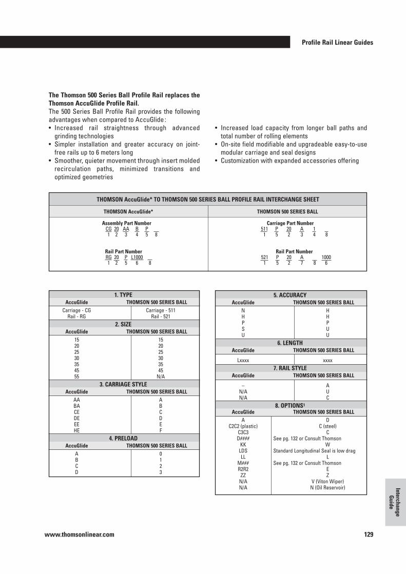
Profile Rail Linear Guides
www.thomsonlinear.com 129
Interchange G
uide
The Thomson 500 Series Ball Profile Rail replaces the Thomson AccuGlide Profile Rail .The 500 Series Ball Profile Rail provides the following advantages when compared to AccuGlide :• Increased rail straightness through advanced
grinding technologies• Simpler installation and greater accuracy on joint-
free rails up to 6 meters long• Smoother, quieter movement through insert molded
recirculation paths, minimized transitions and optimized geometries
• Increased load capacity from longer ball paths and total number of rolling elements
• On-site field modifiable and upgradeable easy-to-use modular carriage and seal designs
• Customization with expanded accessories offering
1 . TYPE AccuGlide THOMSON 500 SERIES BALL Carriage - CG Carriage - 511 Rail - RG Rail - 521 2 . SIZE AccuGlide THOMSON 500 SERIES BALL 15 15 20 20 25 25 30 30 35 35 45 45 55 N/A 3 . CARRIAGE STYLE AccuGlide THOMSON 500 SERIES BALL AA A BA B CE C DE D EE E HE F 4 . PRELOAD AccuGlide THOMSON 500 SERIES BALL A 0 B 1 C 2 D 3
Assembly Part Number Carriage Part Number CG 20 AA B P 511 P 20 A 1 1 2 3 4 5 8 1 5 2 3 4 8
Rail Part Number Rail Part Number RG 20 P L1000 521 P 20 A 1000 1 2 5 6 8 1 5 2 7 8 6
THOMSON AccuGlide* TO THOMSON 500 SERIES BALL PROFILE RAIL INTERCHANGE SHEET
THOMSON AccuGlide* THOMSON 500 SERIES BALL
5 . ACCURACY AccuGlide THOMSON 500 SERIES BALL N H H H P P S U U U 6 . LENGTH AccuGlide THOMSON 500 SERIES BALL
Lxxxx xxxx 7 . RAIL STYLE AccuGlide THOMSON 500 SERIES BALL
– A N/A U N/A C 8 . OPTIONS1
AccuGlide THOMSON 500 SERIES BALL A D C2C2 (plastic) C (steel) C3C3 C D#### See pg . 132 or Consult Thomson KK W LDS Standard Longitudinal Seal is low drag LL L M### See pg . 132 or Consult Thomson R2R2 E ZZ Z N/A V (Viton Wiper) N/A N (Oil Reservoir)
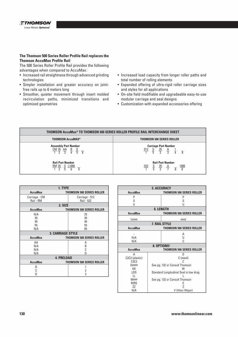
www.thomsonlinear.com130
The Thomson 500 Series Roller Profile Rail replaces the Thomson AccuMax Profile RailThe 500 Series Roller Profile Rail provides the following advantages when compared to AccuMax :• Increased rail straightness through advanced grinding
technologies• Simpler installation and greater accuracy on joint-
free rails up to 6 meters long• Smoother, quieter movement through insert molded
recirculation paths, minimized transitions and optimized geometries
• Increased load capacity from longer roller paths and total number of rolling elements
• Expanded offering of ultra-rigid roller carriage sizes and styles for all applications
• On-site field modifiable and upgradeable easy-to-use modular carriage and seal designs
• Customization with expanded accessories offering
Assembly Part Number Carriage Part Number CM 35 AA B S 512 S 35 A 1 1 2 3 4 5 8 1 5 2 3 4 8
Rail Part Number Rail Part Number RM 35 S L1000 522 S 35 A 1000 1 2 5 6 8 1 5 2 7 8 6
THOMSON AccuMax* TO THOMSON 500 SERIES ROLLER PROFILE RAIL INTERCHANGE SHEET
THOMSON AccuMAX* THOMSON 500 SERIES ROLLER
1 . TYPE AccuMax THOMSON 500 SERIES ROLLER Carriage - CM Carriage - 512 Rail - RM Rail - 522 2 . SIZE AccuMax THOMSON 500 SERIES ROLLER N/A 25 35 35 45 45 55 55 N/A 65 3 . CARRIAGE STYLE AccuMax THOMSON 500 SERIES ROLLER AA A N/A B N/A C N/A D 4 . PRELOAD AccuMax THOMSON 500 SERIES ROLLER B 1 C 2 D 3
5 . ACCURACY AccuMax THOMSON 500 SERIES ROLLER P P S S U U 6 . LENGTH AccuMax THOMSON 500 SERIES ROLLER
Lxxxx xxxx 7 . RAIL STYLE AccuMax THOMSON 500 SERIES ROLLER
– A N/A U N/A C 8 . OPTIONS1
AccuMax THOMSON 500 SERIES ROLLER A D C2C2 (plastic) C (steel) C3C3 C D#### See pg . 132 or Consult Thomson KK W LDS Standard Longitudinal Seal is low drag LL L M### See pg . 132 or Consult Thomson R2R2 E ZZ Z N/A V (Viton Wiper)
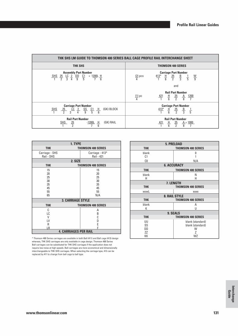
Profile Rail Linear Guides
www.thomsonlinear.com 131
Interchange G
uide
5 . PRELOAD THK THOMSON 400 SERIES blank 0 C1 1 C0 N/A 6 . ACCURACY THK THOMSON 400 SERIES blank N H H 7 . LENGTH THK THOMSON 400 SERIES xxxxL xxxx 8 . RAIL STYLE THK THOMSON 400 SERIES blank A K U 9 . SEALS THK THOMSON 400 SERIES UU blank (standard) SS blank (standard) DD W ZZ Z KK WZ
1 . TYPE THK THOMSON 400 SERIES Carriage - SHS Carriage - 413* Rail - SHS Rail - 421 2 . SIZE THK THOMSON 400 SERIES 15 15 20 20 25 25 30 30 35 35 45 45 55 55 65 N/A
3 . CARRIAGE STYLE THK THOMSON 400 SERIES C A LC B V C LV D R E LR F 4 . CARRIAGES PER RAIL
THK SHS LM GUIDE TO THOMSON 400 SERIES BALL CAGE PROFILE RAIL INTERCHANGE SHEET
THK SHS THOMSON 400 SERIES
* Thomson 400 Series carriages are available in both Ball (411) and Ball cage (413) design whereas, THK SHS carriages are only available in cage design . Thomson 400 Series Ball carriages can be substituted for THK SHS carriages if the application does not require low noise at high speeds . Ball carriages are more economical and dimensionally interchangeable to THK SHS carriages . When selecting the carriage type, 413 can be replaced by 411 to change from ball cage to ball type .
Assembly Part Number Carriage Part Number SHS 25 LC 2 DD C1 + 1200L H (2) pcs 413* H 25 B 1 W 1 2 3 4 9 5 7 6 4 1 6 2 3 5 9
and
Rail Part Number (1) pc 421 H 25 A 1200 4 1 6 2 8 7
Carriage Part Number Carriage Part Number SHS 25 LC 2 SS C1 H (GK) BLOCK 413* H 25 B 1 1 2 3 4 9 5 6 1 6 2 3 5 Rail Part Number Rail Part Number SHS 25 - 1200L H (GK) RAIL 421 H 25 A + 1000 1 2 7 6 1 6 2 8 7
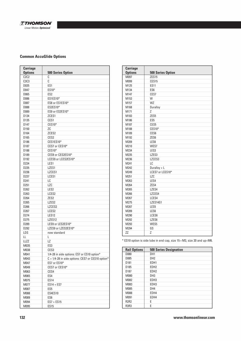
www.thomsonlinear.com132
Common AccuGlide Options
Carriage Options 500 Series Option C2C2 C C3C3 C D035 ES1 D047 ES10* D065 ES2 D086 ES1ES10* D087 ES8 or ES1ES10* D088 ES2ES10* D089 ES9 or ES2ES10* D134 ZCES1 D135 CES1 D147 CES10* D150 ZC D164 ZCES2 D165 CES2 D186 CES1ES10* D187 CES7 or CES10* D188 CES10* D189 CES9 or CES2ES10* D192 LCES9 or LCES2ES10* D234 LES1 D235 LZES1 D236 LZCES1 D237 LCES1 D241 LC D251 LZC D262 LES2 D263 LCES2 D264 ZES2 D265 LZES2 D266 LZCES2 D267 LCES2 D274 LES12 D275 LZES12 D289 LES9 or LES2ES10* D292 LZES9 or LZES2ES10* LDS now standard LL L LLZZ LZ M035 ES3 M038 CES3 M041 1/4-28 in side options: ES7 or ES10 option* M043 C + 1/4-28 in side options: CES7 or CES10 option* M047 ES7 or ES10* M049 CES7 or CES10* M063 CES4 M065 ES4 M075 ES14 M077 ES14 + ES7 M087 ES5 M088 ES4ES10 M089 ES6 M094 ES7 + ES15 M095 ES15
Carriage Options 500 Series Option M097 ZES15 M099 CES15 M125 ES11 M134 ES6 M147 CES7 M153 W M157 WZ M168 Duralloy M171 Z M183 ZES5 M186 ES5 M187 CES5 M188 CES10* M189 CES6 M192 ZES6 M209 LES6 M210 WES7 M234 LES3 M235 LZES3 M236 LZCES3 M241 LC M242 Duralloy + L M249 LCES7 or LCES10* M251 LZC M263 LES4 M264 ZES4 M265 LZES4 M266 LZCES4 M267 LCES4 M275 LZES14G1 M287 LES5 M289 LES6 M290 LCES6 M292 LZES6 M293 WES5 M294 GS ZZ Z
Rail Options 500 Series Designation D080 DH1 D085 DH2 D181 EDH1 D185 EDH2 D187 EDH2 M080 DH3 M082 EDH3 M083 EDH3 M085 DH4 M088 EDH4 M091 EDH4 R2R2 E R3R3 E
* ES10 option is side lube in end cap, size 15 = M3, size 20 and up=M6 .
Profile Rail Linear Guides
www.thomsonlinear.com 133
Interchange G
uide
NOTES :

www.thomsonlinear.com134
NOTES :


EUROPEUnited KingdomThomsonOffice 9, The BarnsCaddsdown Business ParkBidefordDevon, EX39 3BTPhone: +44 (0) 1271 334 500E-mail: [email protected]
GermanyThomsonNürtinger Straße 7072649 WolfschlugenPhone: +49 (0) 7022 504 0Fax: +49 (0) 7022 504 405E-mail: [email protected]
FranceThomsonPhone: +33 (0) 243 50 03 30Fax: +33 (0) 243 50 03 39E-mail: [email protected]
ItalyThomsonLargo Brughetti20030 Bovisio MasciagoPhone: +39 0362 594260Fax: +39 0362 594263E-mail: [email protected]
SpainThomsonE-mail: [email protected]
SwedenThomsonEstridsväg 1029109 KristianstadPhone: +46 (0) 44 24 67 00Fax: +46 (0) 44 24 40 85E-mail: [email protected]
SOUTH AMERICA Brasil Thomson Av. Tamboré, 1077 Barueri, SP – 06460-000 Phone: +55 (11) 3616-0191 Fax: +55 (11) 3611-1982 E-mail: [email protected]
USA, CANADA and MEXICOThomson203A West Rock RoadRadford, VA 24141, USAPhone: 1-540-633-3549Fax: 1-540-633-0294E-mail: [email protected]: literature.thomsonlinear.com ASIA Asia Pacific Thomson E-mail: [email protected] ChinaThomsonRm 2205, Scitech Tower22 Jianguomen Wai StreetBeijing 100004Phone: +86 400 6661 802Fax: +86 10 6515 0263E-mail: [email protected]
IndiaThomsonc/o Fluke Technologies Pvt. Ltd.#424, Deodhar Center, Marol Maroshi Road, Andheri – E, Mumbai – 400059 IndiaPhone: +91 22 29207641E-mail: [email protected]
JapanThomsonMinami-Kaneden 2-12-23, SuitaOsaka 564-0044 JapanPhone: +81-6-6386-8001Fax: +81-6-6386-5022E-mail: [email protected]
KoreaThomsonF7 Ilsong Bldg, 157-37Samsung-dong, Kangnam-gu,Seoul, Korea (135-090)Phone: +82 2 6917 5049Fax: +82 2 528 1456E-mail: [email protected]
Profile_Rail_Linear_Guides_CTUK-0001-04B | 20160511SKErrors and technical alterations reserved. It is the responsibility of the product user to determine the suitability of this product for a specific application. All trademarks property of their respective owners. © Thomson Industries, Inc. 2016
www.thomsonlinear.com