precision altimeter operator manual - duke … altimeter operators manual pa200 / pa500 altimeter...
TRANSCRIPT

Tritech International Ltd. Pa200500
Supplied by
TritechPA200 / PA500
Precision Altimeter
Operators Manual
PA200 / PA500 Altimeter Operators Manual Page 2
Tritech International Ltd. Pa200500
TECHNICAL SUPPORT......................................................................................................3
WARRANTY........................................................................................................................3Trademarks................................................................................................................................................ 4
INTRODUCTION.................................................................................................................4
ALTIMETER DESCRIPTION...............................................................................................5
OPTIONAL 6800M DEPTH UNIT........................................................................................5
INTERNAL SWITCH SETTINGS ........................................................................................5
GENERAL ASSEMBLY ......................................................................................................6
Altimeter Configuration Record ................................................................................................................. 8
WIRING CONFIGURATION................................................................................................9
Standard Connector .................................................................................................................................... 9
Optional Connector ..................................................................................................................................... 9
ALTIMETER INSTALLATION ...........................................................................................10
Mounting..................................................................................................................................................... 10
Operation .................................................................................................................................................... 10
ALTIMETER MAINTENANCE...........................................................................................10
Altimeter Spares......................................................................................................................................... 10
Removal and Replacement of Underwater Connector-(Standard Unit). .............................................. 10Service Tools............................................................................................................................................ 10Preparation............................................................................................................................................... 10Removal ................................................................................................................................................... 10Replacement ............................................................................................................................................ 10
Disassembly and Assembly of the Altimeter .......................................................................................... 11Service tools............................................................................................................................................. 11Preparation............................................................................................................................................... 11Removal ................................................................................................................................................... 11Replacement ............................................................................................................................................ 11
PA200 / PA500 Altimeter Operators Manual Page 3
Tritech International Ltd. Pa200500
TECHNICAL SUPPORT
Contact your local agent or
Tritech International Ltd
Telephone : ++ 44 1224 744 111Fax : ++ 44 1224 741 771
An out of hours emergency number is available by ringing the above telephone number
If you have cause to use our Technical Support service, please ensure that you have the following details athand prior to calling :
• System Serial Number ( if applicable )• Software Revision Number• Fault Description• Any remedial action implemented
Due to the expansion of equipment capabilities and the fact that new sub-modules are continually beingintroduced, this manual cannot detail every aspect of the operation.
WARRANTYTritech International Limited herein after referred to as T.I.
T.I. Warrants that at the time of shipment all products shall be free from defects in material and workmanshipand suitable for the purpose specified in the product literature.1. The system warranty commences at the date of customer acceptance and runs for a period of 180 days.The Customer Acceptance Test must be performed either at Tritech International or at one of their approveddistributors unless otherwise specified in writing. The warranty does not apply unless the recommendedmaintenance instructions have been followed and does not apply to defects resulting from normal wear andtear, incorrect operation, fire, water or lightning damage or damage caused by variations in a ships voltage,or from any other circumstances which arise after delivery and beyond the control of T.I.2. Warranty service is performed at the discretion of T.I. either by repair or replacement of the equipment inquestion.3. The warranty does not cover personnel transportation and per diem allowances related to repair orreplacement.4. The warranty is subject to the following conditions:-a) The system must have been sold by T.I. or one of their authorised representatives.b) The system must have been installed and commissioned in accordance with approved technical standardsand specifications and for the purpose for which the system was designed. c) Any claim must be notified in writing to T.I. without delay upon discovery of a defect. d) Defective parts have to be forwarded to T.I. adequately packaged and by suitable means of transport,freight paid and with a report stating the defect. The replacement parts or equipment covered by thewarranty will be returned to the customer, carriage paid by T.I.5. The warranty shall become invalid if the customer repairs or modifies the equipment and componentswithout written authority from T.I.6. The warranty is not transferable, except as or applies to Purchaser first then to customer.7. All further claims on any grounds whatsoever, are excluded.
PA200 / PA500 Altimeter Operators Manual Page 4
Tritech International Ltd. Pa200500
TrademarksMicrosoft and Windows 3.1 are registered trademarks of the Microsoft CorporationIBM and AT are registered trademarks of International Business Machines Corporation.
Whilst every effort is taken to keep all the information contained in this document up to date, information inthis document is subject to change without notice and does not represent a commitment on the part ofTritech International Ltd. No part of this manual may be reproduced or transmitted in any form or by anymeans, including photocopying or recording for any purpose without the express written permission ofTritech International or System Technologies. Tritech International Ltd System Technologies
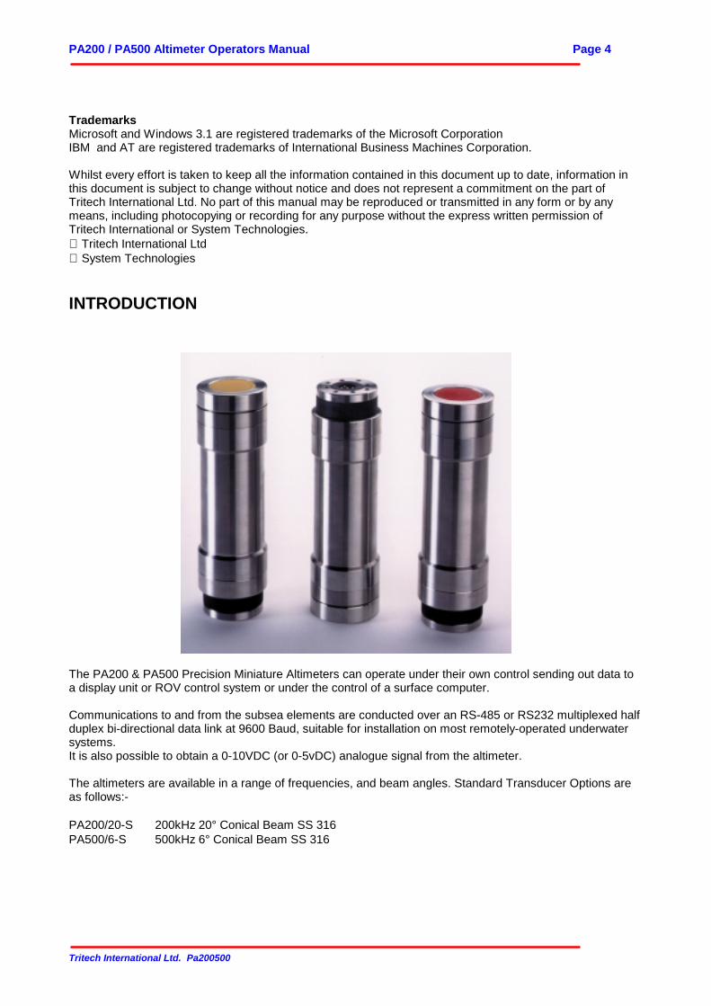
INTRODUCTION
The PA200 & PA500 Precision Miniature Altimeters can operate under their own control sending out data toa display unit or ROV control system or under the control of a surface computer.
Communications to and from the subsea elements are conducted over an RS-485 or RS232 multiplexed halfduplex bi-directional data link at 9600 Baud, suitable for installation on most remotely-operated underwatersystems.It is also possible to obtain a 0-10VDC (or 0-5vDC) analogue signal from the altimeter.
The altimeters are available in a range of frequencies, and beam angles. Standard Transducer Options areas follows:-
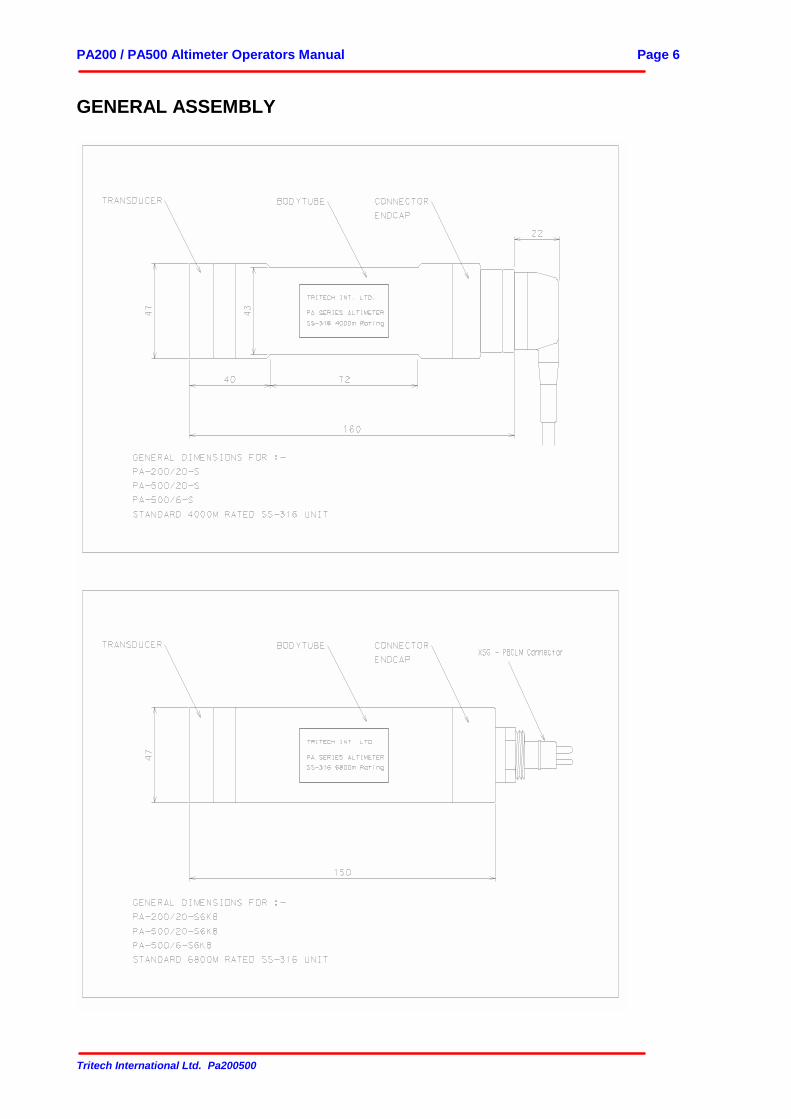
PA200/20-S 200kHz 20° Conical Beam SS 316PA500/6-S 500kHz 6° Conical Beam SS 316
PA200 / PA500 Altimeter Operators Manual Page 5
Tritech International Ltd. Pa200500
ALTIMETER DESCRIPTION
STANDARD 4000M DEPTH UNITThe PA200 / PA500 is a sonar ranging device which mounted vertically gives depth above the sea bed or inany other attitude provides a subsea distance measuring device. The altimeter can be configured to operateon its own or under control from an external unit and has a 6 pin connector allowing both analogue outputand serial communications to be available simultaneously.
The altimeter incorporates a fixed crystal transducer which is matched to the range and resolution required.The altimeter data is transmitted via an underwater connector to a processor or data display unit, in digitalor analogue signal form.
OPTIONAL 6800M DEPTH UNITThe PA200/500-S6K8 is designed for use at greater depths than the normal PA200/500-S Altimeters. Thealtimeter uses a Brantner 4 pin connector and can be configured for analogue only or serial output only.
INTERNAL SWITCH SETTINGSThe PA altimeters have a number of internal switches. These may be used to set the altimeters to differentconfigurations.
NOTE : IF YOU DO NOT KNOW WHAT YOU ARE DOING THEN DON’T TOUCH THE SWITCHES ASYOU MAY WELL CAUSE DAMAGE TO THE UNIT.
A list of the various switch configurations is available from Technical Support at Tritech.
PA200 / PA500 Altimeter Operators Manual Page 6
Tritech International Ltd. Pa200500
GENERAL ASSEMBLY
PA200 / PA500 Altimeter Operators Manual Page 7
Tritech International Ltd. Pa200500
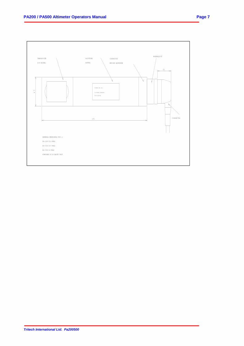
W ATERBLO CK
CO N N ECTO R
GEN ERAL DIM EN SIO N S FO R :-
PA- 200/ 20- PRA2
PA- 500/ 20- PRA2
PA- 500/ 6- PRA2
STAN DARD R/ A PLASTIC U N IT
170
47
TRITECH INT. LTD.
PA SERIES ALTIM ETER
RA TX ACETAL
TRAN SDU CER
R/ A ACETAL
BO DYTU BE
ACETAL
CO N N ECTO R
EN DCAP ALU M IN IU M
22
PA200 / PA500 Altimeter Operators Manual Page 8
Tritech International Ltd. Pa200500
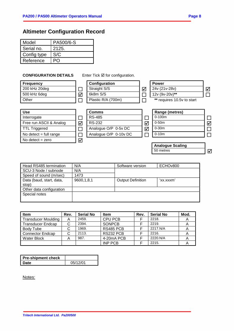
Altimeter Configuration Record
Model PA500/6-SSerial no. 2125.Config type S/CReference PO
CONFIGURATION DETAILS Enter Tick ! for configuration.
Frequency Configuration Power200 kHz 20deg " Straight S/S ! 24v (21v-28v) !500 kHz 6deg ! 6k8m S/S " 12v (9v-20v)** "Other " Plastic R/A (700m) " ** requires 10.5v to start
Use Comms Range (metres)Interrogate " RS-485 " 0-100m "Free run ASCII & Analog ! RS-232 ! 0-50m !TTL Triggered " Analogue O/P 0-5v DC ! 0-30m "No detect = full range " Analogue O/P 0-10v DC " 0-10m "No detect = zero !
Analogue Scaling50 metres !
Head RS485 termination N/A Software version ECHOv800SCU-3 Node / subnode N/ASpeed of sound (m/sec) 1473Data (baud, start, data,stop)
9600,1,8,1 Output Definition ‘xx.xxxm’
Other data configurationSpecial notes
Item Rev. Serial No Item Rev. Serial No Mod.Transducer Moulding A 2459. CPU PCB F 2218. ATransducer Endcap C 2394. SONPCB F 2219. ABody Tube C 1969. RS485 PCB F 2217.N/A AConnector Endcap C 2113. RS232 PCB F 2216. AWater Block A 987. 4-20mA PCB F 2220.N/A A
INP PCB F 2215. A
Pre-shipment checkDate 05/12/01
Notes:
PA200 / PA500 Altimeter Operators Manual Page 9
Tritech International Ltd. Pa200500
WIRING CONFIGURATION
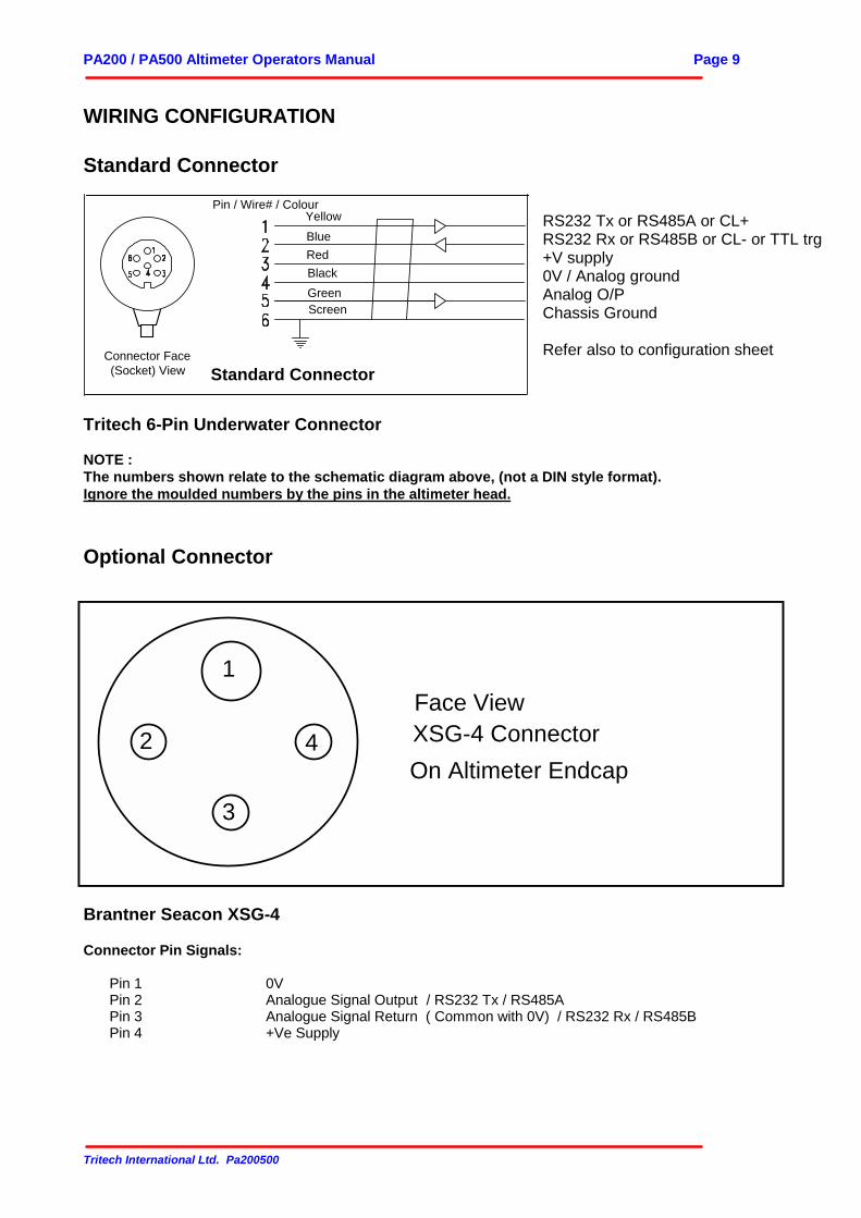
Standard Connector
YellowBlueRedBlackGreenScreen
Pin / Wire# / Colour
Standard ConnectorConnector Face(Socket) View
RS232 Tx or RS485A or CL+RS232 Rx or RS485B or CL- or TTL trg+V supply0V / Analog groundAnalog O/PChassis Ground
Refer also to configuration sheet
Tritech 6-Pin Underwater Connector
NOTE :The numbers shown relate to the schematic diagram above, (not a DIN style format).Ignore the moulded numbers by the pins in the altimeter head.
Optional Connector
Face View 1
2
3
4 XSG-4 ConnectorOn Altimeter Endcap
Brantner Seacon XSG-4
Connector Pin Signals:
Pin 1 0VPin 2 Analogue Signal Output / RS232 Tx / RS485APin 3 Analogue Signal Return ( Common with 0V) / RS232 Rx / RS485BPin 4 +Ve Supply
PA200 / PA500 Altimeter Operators Manual Page 10
Tritech International Ltd. Pa200500
ALTIMETER INSTALLATION
Caution : Before applying power to the altimeter, ensure that power and signal linesare correctly connected according to the diagram in the configuration information.Incorrect connections may damage the unit.
MountingThe altimeter should be securely mounted by insulated clamps in a position that gives an unimpeded path forthe sounder beam, and as far from frame structures as possible. If being used as a depth sounder, it shouldbe mounted as vertically as possible.
OperationIf supplied with the Analogue Output and Automatic Run on Power Up options, the altimeter will start rangingas soon as power is applied. The Analogue (and / or Serial Data) output will then reflect the range of thenearest echo. Otherwise the unit will need an interrogate signal as described in the configuration information.
ALTIMETER MAINTENANCEThe PA200 and PA500 Precision Altimeter consists of Transducer and Connector Endcaps that connect to aBody tube using a screw thread, with O-ring seals. Inside are contained four PCB's. The standard unit has a6-way underwater connector fastened 4 socket cap screws, the connector is sealed using an O-ring. Theoptional 4 pin connector is fitted to the endcap using a screw thread and O ring.
Altimeter SparesWhen ordering spares please specify the units frequency and beam angle, these are engraved on thetransducer endcap, and also recorded on the configuration sheet in the front of the manual along with otherdetails of the unit such as EPROM version and range and output specification.
Removal and Replacement of Underwater Connector-(Standard Unit).
Service Tools2.5mm Allen keyClean absorbent wipesLubricant A ( Silicon grease MS-33 )Lubricant B ( Fluoro-silicon grease MS-5341)
PreparationRinse the altimeter unit and connector in freshwater, and dry with absorbent wipes
RemovalFirst undo the four cap screws holding the connector on to the body tube. Grasp the altimeter firmly in onehand, and the connector body in the other. Gently pull the connector from the body tube.
ReplacementTo fit the connector to the body tube, make sure the connector face, o-ring, and body tube face, are cleanand undamaged. Use a light computer grade cleaning solvent (e.g. Flourinert) to clean components. Do notuse powerful solvents like Trichloroethylene.
Lubricate the threaded screw holes with Lub.B, to prevent the threads seizing. Lightly grease the o-ring withLub. A and refit it into the sealing groove.
PA200 / PA500 Altimeter Operators Manual Page 11
Tritech International Ltd. Pa200500
Visual align the connector socket to the pins of the sonar tube, and push the connector firmly on. Fit the fourcap screws, tighten them evenly and firmly. Visually check that the connector is fitted flush to the tube. DONOT OVER TIGHTEN.
When mounting the altimeter, take care not to strain the connector or cable, and make sure that the cable iswell secured to avoid damage.If the connector is not being re-fitted, cover the endcap to prevent dirt and moisture entering the unit.
Disassembly and Assembly of the Altimeter
Service toolsClean absorbent wipesLubricant A ( Silicon grease MS-33 )
PreparationRinse the altimeter unit and connector in freshwater, and dry with absorbent wipes
RemovalNext grasp the altimeter connector endcap firmly in one hand, and the body tube in the other. Gently unscrewthe body tube away from the connector endcap. The electronics block will then slide out of the housing,attached to the connector endcap. The transducer may be unscrewed from the opposite end of the body tubein the same way.
ReplacementClean all parts and check they are undamaged. Carefully inspect O-rings for damage and replace ifnecessary. O-rings, O-ring grooves and mating surfaces should be lightly greased before reassembly. Beforereplacing, ensure that the earth loop on the electronics block is secure and sprung so that it will contact theinside face of the body tube when it is fitted.