preaction system with model dv-5 deluge valve...
TRANSCRIPT

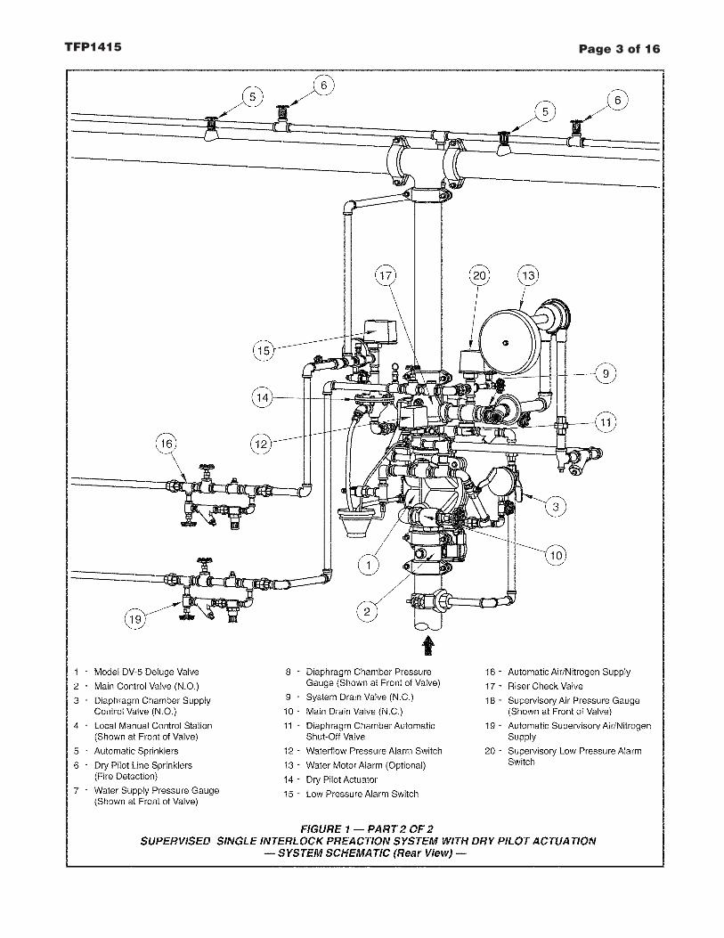
GeneralDescriptionThe Model DV-5 Supervised Single In-terlock Preaction System with Dry PilotActuation (Fig. 1) utilizes automaticsprinklers and a supplemental detec-tion system. The supplemental detec-tion system is comprised of dry pilotlines and pilot sprinklers. Actuation ofthe detection system automatically op-erates (releases) the Model DV-5 Del-uge Valve, allowing water to flow intothe sprinkler piping system and to bedischarged from any sprinklers thatmay be open.
In accordance with the requirementsof the National Fire Protection Asso-ciation, a preaction system employingmore than 20 automatic sprinklers is tohave the sprinkler piping automaticallysupervised to monitor the overall in-tegrity of the system. In the case of aSupervised Single Interlock PreactionSystem, a Riser Check Valve (thatdoes not require the use of primingwater) provides an air check so thatthe system can be automatically pres-surized with a nominal supervisory airor nitrogen pressure of 10 psi (0,69bar). A supervisory low pressure alarmswitch that is set to transfer its contactsat nominally 5 psi (0,34 bar), on de-creasing pressure, is utilized to indi-cate whether there are any abnormalleaks in the sprinkler system piping.Loss of air pressure from the systemas a result of a damaged sprinkler orbroken piping will not cause the DV-5Valve to open — the air pressure is forsupervisory alarm only.
Typically, the system designer selectsthe detection components for a singleinterlock preaction system that will re-spond to a fire sooner than the auto-matic sprinklers. Consequently, thesystem will experience a minimal delayin water delivery over that for a wetpipe sprinkler system because thesystem will have essentially filled withwater before a sprinkler operates. In
the case of dry pilot actuation, the sys-tem designer selects pilot sprinklersthat will operate sooner than the auto-matic sprinklers chosen for use on thesprinkler piping.
Supervised single interlock preactionsystems are generally used to protectareas where there is danger of seriouswater damage that might result fromdamaged automatic sprinklers or pip-ing. Typically, such areas include com-puter rooms, storage areas for valu-able artifacts, libraries, and archives.
Single interlock preaction systems are
also effectively used to protect proper-ties where a pre-alarm of a possiblefire condition may allow time for fireextinguishment by alternate suppres-sion means, prior to a sprinkler dis-charge. In the event the fire cannototherwise be extinguished, the preac-tion sprinkler system will then performas the primary fire protection system.
The Model DV-5 Deluge Valve (de-scribed in Technical Data SheetTFP1305) is a diaphragm style valvethat depends upon water pressure in
Page 1 of 16 TFP1415SEPTEMBER, 2004
Preaction System with Model DV-5 Deluge ValveSingle Interlock, Supervised — Dry Pilot Actuation1-1/2 thru 8 Inch (DN40 thru DN200)
Technical Services: Tel: (800) 381-9312 / Fax: (800) 791-5500
(TEXT CONTINUED ON PAGE 9)

Page 2 of 16 TFP1415
Page 3 of 16TFP1415

Page 4 of 16 TFP1415

TFP1415
Page 6 of 16 TFP1415

Page 7 of 16TFP1415

Page 8 of 16 TFP1415
FIGURE 31-1/2 thru 8 INCH (DN40 thru DN200) MODEL DV-5 DELUGE VALVES
SUPERVISED SINGLE INTERLOCK PREACTION WITH DRY PILOT ACTUATION TRIM— NOMINAL INSTALLATION DIMENSIONS —
(800,1)31.50
(830,3)32.69
CHAMBER SUPPLYCONNECTING TRIM
(FIELD FABRICATED)
MAINCONTROL
VALVE
A
2" NPSDRAIN
DIAPHRAGM
L
1/2" NPS
G
H KJ
LEFT VIEW FRONT VIEW
*
1-1/4" NPSDRAIN
B
F
M
MINIMUM CLEARANCE.*
(635,0)25.00
(627,1)24.69
(723,9)28.50
E*
D*C*
(933,5)36.75
(231,8)9.13
(266,7)10.50
(152,4)6.00
(152,4)6.00
(390,5)15.38
(DN50)2"
(79,4)3.13
(177,8)7.00
(225,4)8.88
(330,2)13.00
(266,7)10.50
(147,6)5.81
(147,6)5.81
(76,2)3.00
(101,6)4.00
(376,2)14.81
(DN40)1-1/2"
(101,6)4.00
(177,8)7.00
(181,0)7.13
(330,2)13.00
(76,2)3.00
(177,8)7.00
(79,4)3.13
(254,0)10.00
(289,0)11.38
(298,5)11.75
(363,5)14.31
(454,0)17.88
(476,3)18.75
(266,7)10.50
(165,1)6.50
(200,0)7.88
(217,5)8.56
(252,4)9.94
(158,8)6.25
(181,0)7.13
(9,5)0.38
(39,7)1.56
(644,5)25.38
(752,5)29.63
(44,5)1.75
(88,9)3.50
(266,7)10.50
(181,0)7.13
(198,4)7.81
(265,1)10.44
(266,7)10.50
(170,0)6.69
(108,0)4.25
(536,6)21.13
(DN80)3"
(368,3)14.50
(42,9)1.69
(177,8)7.00
A B C D E G H J K L MFNominal Installation Dimensions in Inches and (mm)
SizeValve
(170,0)6.69
(6,4)0.25
(DN100)4"
(DN150)6"
(158,8)6.25
(304,8)12.00
(406,4)16.00
(539,8)21.25
(273,1)10.75
(269,9)10.63
(927,1)36.50
(DN200)8"
(44,5)1.75
(266,7)10.50
(158,8)6.25
(181,0)7.13
(181,0)7.13

the Diaphragm Chamber to hold theDiaphragm closed against the watersupply pressure. When the DV-5 Valveis set for service, the DiaphragmChamber is pressurized through thetrim connections from the inlet side ofthe system’s main control valve, suchas an O.S.&Y. gate valve or butterflyvalve (Fig. 1).
Opening of a pilot sprinkler, releasespneumatic pressure from the pilot line.In turn, the Dry Pilot Actuator (Item D3- Fig. 2A) opens and releases waterfrom the Diaphragm Chamber fasterthan it can be replenished through the1/8 inch (3,2 mm) restriction providedby the Model ASV-1 Automatic Shut-Off Valve in the diaphragm supply con-nection (Item 5 - Fig. 2A, also de-scribed in Technical Data SheetTFP1384). This results in a rapid pres-sure drop in the Diaphragm Chamberto below the valve trip point. The watersupply pressure then forces the Dia-phragm open, permitting water to flowinto the system piping, as well asthrough the Alarm Port to actuate thesystem alarms
As water flows into the system, thepilot chamber of the Model ASV-1Automatic Shut-Off Valve (Item 5 - Fig.2A) becomes pressurized and theASV-1 automatically shuts off the dia-phragm chamber supply flow to theDV-5 Diaphragm Chamber. Shuttingoff the diaphragm chamber supply flowprevents the DV-5 Diaphragm Cham-ber from becoming re-pressurized,thereby preventing inadvertent closingof the DV-5 during a fire (as may be thecase if an actuation device other thana pilot sprinkler were to be closed afterits initial operation, for example a re-mote manual control station).
WARNINGThe Model DV-5 Supervised Single In-terlock Preaction System with Dry PilotActuation Trim described herein mustbe installed and maintained in compli-ance with this document, as well aswith the applicable standards of theNational Fire Protection Association,in addition to the standards of anyother authorities having jurisdiction.Failure to do so may impair the per-formance of the related devices.
The owner is responsible for maintain-ing their fire protection system and de-vices in proper operating condition.The installing contractor or manufac-turer should be contacted with anyquestions.
TechnicalDataApprovalsUL and C-UL Listed.
Deluge ValveModel DV-5.
Riser Check ValveModel CV-1FR.
NOTE1-1/2 inch (DN40) risers utilize a 2 inch(DN50) Riser Check Valve in combina-tion with the 1-1/2 inch (DN40) ModelDV-5 Deluge Valve.
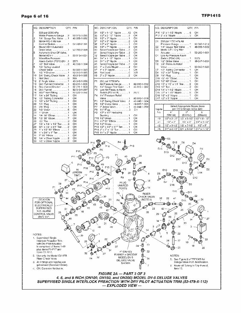
Valve TrimThe Supervised Single Interlock Pre-action System With Dry Pilot ActuationTrim (Fig. 2A/2B) forms a part of thelaboratory listings and approvals. Thetrim is necessary for proper operationof the DV-5 Valve.
Each package of trim includes the fol-lowing items:
• Water Supply Pressure Gauge• Diaphragm Chamber
Pressure Gauge• Diaphragm Chamber Connections• Manual Control Station• Main Drain Valve• System Drain Valve• Alarm Test Valve• Automatic Drain Valve• System Air Pressure Gauge• Air Supply Connections• Low Air Pressure Supervisory
Switch• Waterflow Pressure Alarm Switch• Dry Pilot Actuator• Dry Pilot Line Pressure Gauge• Dry Pilot Line Low Pressure Alarm
Switch
To ease field assembly of the trim ar-rangement, the trim components areprovided par tially assembled asshown in Figure 2B.
The trim arrangement is provided withgalvanized or black nipples and fit-tings. The galvanized trim is intendedfor non-corrosive or corrosive condi-tions, whereas the black trim is princi-pally intended for use with AFFF sys-tems.
NOTEWhen the system pressure is greaterthan 175 psi (12,1 bar), provision is tobe made to replace the standard order300 psi (20,7 bar) Water PressureGauges, shown in Figure 2A/2B with
separately ordered 600 psi (41,4 bar)Water Pressure Gauges.
Detection SystemIn order for a single interlock preactionsystem to be hydraulically calculatedas a wet pipe system, as opposed to adry pipe sprinkler system, the detec-tion system must be designed to oper-ate sooner than the automatic sprin-klers on the sprinkler piping. In thecase of dry pilot actuation, the systemdesigner selects pilot sprinklers thatwill operate sooner than the automaticsprinklers chosen for use on the sprin-kler piping.
The Supervised Single Interlock Pre-action System With Dry Pilot ActuationTrim provides for connection of a de-tection system consisting of dry pilotline sprinklers (heat detectors) andmanual control stations intercon-nected with minimum 1/2 inch (DN15)Schedule 40 steel pipe. The pilot line,which is pressurized with air or nitro-gen, is connected to the “Dry Pilot De-tection” connection shown in Figure2B. Nominal installation dimensionsfor the Supervised Single InterlockPreaction System With Dry Pilot Ac-tuation Trim are shown in Figure 3.
Dry pilot line sprinklers are to be mini-mum 5.6 K-factor orifice listed or ap-proved automatic sprinklers. ManualControl Stations are to be the ModelMC-1 described in Technical DataSheet TFP1382.
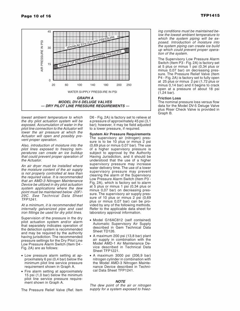
The Dry Pilot Actuation Trim is pro-vided with a listed and approved ModelDP-1 Dry Pilot Actuator, which is de-scribed in Technical Data SheetTFP1380. The Actuator is rated for useat a maximum pilot service pressure of50 psi (3,4 bar) and a maximum watersupply service pressure of 250 psi(17,2 bar).
Graph A shows the “minimum pilot lineservice pressure” as a function of thewater supply pressure. The pressure inthe dry pilot actuation system must beautomatically maintained using one ofthe following maintenance devices, asappropriate.
• Model AMD-1 Air Maintenance De-vice (pressure reducing type), referto Technical Data Sheet TFP1221.
• Model AMD-2 Air Maintenance De-vice (compressor control type), referto Technical Data Sheet TFP1231.
• Model AMD-3 Nitrogen Mainte-nance Device (high pressure reduc-ing type), refer to Technical DataSheet TFP1241.
NOTESThe dew point of the pilot line air pres-sure must be maintained below the
Page 9 of 16TFP1415
lowest ambient temperature to whichthe dry pilot actuation system will beexposed. Accumulation of water in thepilot line connection to the Actuator willlower the air pressure at which theActuator will open and possibly pre-vent proper operation.
Also, introduction of moisture into thepilot lines exposed to freezing tem-peratures can create an ice buildupthat could prevent proper operation ofthe Actuator.
An air dryer must be installed wherethe moisture content of the air supplyis not properly controlled at less thanthe required value. It is recommendedthat an AMD-3 Nitrogen MaintenanceDevice be utilized in dry pilot actuationsystem applications where the dewpoint must be maintained below -20F/-29C. See Technical Data SheetTFP1241.
At a minimum, it is recommended thatinternally galvanized pipe and castiron fittings be used for dry pilot lines.
Supervision of the pressure in the drypilot actuation system and/or alarmthat separately indicates operation ofthe detection system is recommendedand may be required by the authorityhaving jurisdiction. The recommendedpressure settings for the Dry Pilot LineLow Pressure Alarm Switch (Item D4 -Fig. 2A) are as follows:
• Low pressure alarm setting at ap-proximately 6 psi (0,4 bar) below theminimum pilot line service pressurerequirement shown in Graph A.
• Fire alarm setting at approximately15 psi (1,0 bar) below the minimumpilot line service pressure require-ment shown in Graph A.
The Pressure Relief Valve (Ref. Item
D6 - Fig. 2A) is factory set to relieve ata pressure of approximately 45 psi (3,1bar); however, it may be field adjustedto a lower pressure, if required.
System Air Pressure RequirementsThe supervisory air (nitrogen) pres-sure is to be 10 plus or minus 2 psi(0,69 plus or minus 0,07 bar). The useof a higher supervisory pressure issubject to approval by the AuthorityHaving Jurisdiction, and it should beunderstood that the use of a highersupervisory pressure may increasewater delivery time. The use of a lowersupervisory pressure may preventclearing the alarm of the SupervisoryLow Pressure Alarm Switch (Item P3 -Fig. 2A), which is factory set to alarmat 5 plus or minus 1 psi (0,34 plus orminus 0,07 bar) on decreasing pres-sure. The supervisory air supply pres-sure of 10 plus or minus 2 psi (0,69plus or minus 0,07 bar) can be pro-vided by any of the following methods.Refer to the applicable data sheet forlaboratory approval information.
• Model G16AC812 (self contained)Automatic Supervisory Air Supplydescribed in Gem Technical DataSheet TD126.
• A maximum 200 psi (13,8 bar) plantair supply in combination with theModel AMD-1 Air Maintenance De-vice described in Technical DataSheet TFP1221.
• A maximum 3000 psi (206,9 bar)nitrogen cylinder in combination withthe Model AMD-3 Nitrogen Mainte-nance Device described in Techni-cal Data Sheet TFP1241.
NOTEThe dew point of the air or nitrogensupply for a system exposed to freez-
ing conditions must be maintained be-low the lowest ambient temperature towhich the system piping will be ex-posed. Introduction of moisture intothe system piping can create ice buildup which could prevent proper opera-tion of the system.
The Supervisory Low Pressure AlarmSwitch (Item P3 - Fig. 2A) is factory setat 5 plus or minus 1 psi (0,34 plus orminus 0,07 bar) on decreasing pres-sure. The Pressure Relief Valve (ItemP4 - Fig. 2A) is factory set to fully openat 25 plus or minus 2 psi (1,72 plus orminus 0,14 bar) and it begins to crackopen at a pressure of about 18 psi(1,24 bar).
Friction LossThe nominal pressure loss versus flowdata for the Model DV-5 Deluge Valveplus Riser Check Valve is provided inGraph B.
Page 10 of 16 TFP1415
GRAPH AMODEL DV-5 DELUGE VALVES
— DRY PILOT LINE PRESSURE REQUIREMENTS —
WATER SUPPLY PRESSURE IN PSI
100
RANGE OF ACTUATOR OPENING PRESSUREMINIMUM SYSTEM AIR PRESSURE
AIR
PR
ES
SU
RE
INP
SI
20 60
15
0
30
45
140 180 250200

Page 11 of 16TFP1415
200 400 1000 3000200060010050
FLOW RATE IN GALLONS PER MINUTE (GPM)
3.0
NO
MIN
AL
PR
ES
SU
RE
DR
OP
IN P
OU
ND
S P
ER
SQ
UA
RE
INC
H(P
SI)
0.8
0.4
0.5
0.6
0.7
1.00.9
2.0
6.0
4.0
5.0
9.0
7.0
8.0
10.0
15.0
FLOW RATE IN LITRES PER MINUTE (LPM)
200 1000600400
(1 GPM = 3,785 LPM)
2000 70003000 5000 10000
(1P
SI=
0,06
895
BA
R)
NO
MIN
AL
PR
ES
SU
RE
DR
OP
IN B
AR
0,040
0,030
0,050
0,080
0,060
0,070
0,0900,100
0,200
0,800
0,400
0,300
0,600
0,500
0,700
1,0000,900
2 IN
CH
(DN
50)
1-1/
2IN
CH
(DN
40)
6 IN
CH
(DN
150)
4 IN
CH
(DN
100)
3 IN
CH
(DN
80)
8 IN
CH
(DN
200)
GRAPH BDELUGE AND CHECK VALVE COMBINATION*
— NOMINAL PRESSURE LOSS VERSUS FLOW —
* Model DV-5 Deluge Valve combined with Model CV-1FR Riser Check Valve
**1-1/2 inch Model DV-5 Deluge Valve combined with 2 inch Model CV-1FR Riser Check Valve
The approximate friction loss, based on the Hazen and Williams formula and expressed in equivalent length of pipe with C=120, is asfollows:
15 feet of 1-1/2 Sch. 40 pipe for the 1-1/2 inch Valve Combination** calculated on a typical flow rate of 100 GPM.28 feet of 2 inch Sch. 40 pipe for the 2 inch Valve Combination* calculated on a typical flow rate of 175 GPM.37 feet of 3 inch Sch. 40 pipe for the 3 inch Valve Combination* calculated on a typical flow rate of 350 GPM.48 feet of 4 inch Sch. 40 pipe for the 4 inch Valve Combination* calculated on a typical flow rate of 600 GPM.73 feet of 6 inch Sch. 40 pipe for the 6 inch Valve Combination* calculated on a typical flow rate of 1500 GPM.103 feet of 8 inch Sch. 30 pipe for the 8 inch Valve Combination* calculated on a typical flow rate of 2500 GPM.

InstallationNOTES
1-1/2 inch (DN40) risers utilize a 2 inch(DN50) Riser Check Valve in combina-tion with the 1-1/2 inch (DN40) ModelDV-5 Deluge Valve.
Proper operation of the Model DV-5Deluge Valves depends upon their trimbeing installed in accordance with theinstructions given in this TechnicalData Sheet. Failure to follow the ap-propriate trim diagram may preventthe DV-5 Valve from functioning prop-erly, as well as void listings, approvals,and the manufacturer’s warranties.
The DV-5 Valve must be installed in areadily visible and accessible location.
The DV-5 Valve and associated trimmust be maintained at a minimum tem-perature of 40°F/4°C.
Heat tracing of the DV-5 Valve or itsassociated trim is not permitted. Heattracing can result in the formation ofhardened mineral deposits that are ca-pable of preventing proper operation.
The Model DV-5 Deluge Valve is to beinstalled in accordance with the follow-ing criteria:
Step 1. All nipples, fittings, and de-vices must be clean and free of scaleand burrs before installation. Use pipethread sealant sparingly on male pipethreads only.
Step 2. The DV-5 Valve must betrimmed in accordance with Figure2A/2B.
Step 3. Care must be taken to ensurethat check valves, strainers, globevalves, etc. are installed with the flowarrows in the proper direction.
Step 4. Drain tubing to the drip funnelmust be installed with smooth bendsthat will not restrict flow.
Step 5. The main drain and drip funneldrain may be interconnected provideda check valve is located at least 12inches (300 mm) below the drip funnel.
Step 6. Suitable provision must bemade for disposal of drain water.Drainage water must be directed suchthat it will not cause accidental dam-age to property or danger to persons.
Step 7. Connect the DiaphragmChamber Supply Control Valve to theinlet side of the system’s main controlvalve in order to facilitate setting of theDV-5 Valve (Fig. 3).
Step 8. An Inspector’s Test Connec-tion, as described in the TechnicalData section, must be provided for DryPilot Actuation systems.
Step 9. An Air Maintenance Device, asdescribed in the Technical Data Sec-tion, must be provided for Dry PilotActuation.
Step 10. A desiccant dryer, whenspecified for Dry Pilot Actuation, is tobe installed between a drip leg and theAir Maintenance Device.
Step 11. The Low Pressure AlarmSwitch for Dry Pilot Actuation is to beadjusted as follows:
• Low pressure alarm setting at ap-proximately 6 psi (0,4 bar) below theminimum pilot line service pressurerequirement shown in Graph A.
• Fire alarm setting at approximately15 psi (1,0 bar) below the minimumpilot line service pressure require-ment shown in Graph A.
Step 12. Unused pressure alarmswitch connections must be plugged.
Step 13. The Pressure Relief Valveprovided with the Dry Pilot ActuationTrim is factory set to relieve at a pres-sure of approximately 45 psi (3,1 bar),which can typically be used for a maxi-mum dry pilot actuation system pres-sure of 40 psi (2,8 bar). The PressureRelief Valve may be reset; however, itmust be reset to relieve at a pressurethat is in accordance with the require-ments of the authority having jurisdic-tion.
To reset the Pressure Relief Valve, firstloosen the jam nut and then adjust thecap accordingly — clockwise for ahigher pressure setting or counter-clockwise for a lower pressure setting.After verifying the desired pressuresetting, tighten the jam nut.
Step 14. A suitable automatic supervi-sory air (nitrogen) supply, as describedin the Technical Data Section, is to beinstalled in accordance with the appli-cable Technical Data Sheet and set for10 plus or minus 2 psi (0,69 plus orminus 0,14 bar).
Step 15. A desiccant dryer, when re-quired for the supervisory air supply, isto be installed between a drip leg andthe Model AMD-1 Air Maintenance De-vice or between the Model G16AC812Automatic Supervisory Air Supply andthe Preaction Trim.
Step 16. The Supervisory Low Pres-sure Alarm Switch is to be wired to thesupervisory alarm initiating circuit ofan alarm panel.
Step 17. Conduit and electrical con-nections are to be made in accordancewith the requirements of the authorityhaving jurisdiction and/or the NationalElectric Code.
Step 18. Before a system hydrostatic
test is performed in accordance withNFPA 13 system acceptance test re-quirements, the DV-5 DiaphragmChamber is to be depressurized; theAutomatic Drain Valve (Item 4, Fig. 2A)is to be temporarily replaced with a 1/2inch NPT plug, the 3/32 inch Vent Fit-ting (16 - Fig. 2A) is to be temporarilyreplaced with a 1/4 inch NPT plug, andthe Diaphragm Cover Bolts must beuniformly and securely tightenedusing a cross-draw sequence. Aftertightening, double-check to make cer-tain that all of the Diaphragm CoverBolts are securely tightened.
Valve SettingProcedureSteps 1 through 12 are to be per-formed when initially setting the ModelDV-5 Deluge Valve; after an opera-tional test of the fire protection system;or, after system operation due to a fire.
Step 1. Close the Main Control Valve.
Step 2. Close the Diaphragm Cham-ber Supply Control Valve, the Dry PilotLine Air Supply Control Valve, and theSupervisory Air Supply Control Valve.
Step 3. Open the Main Drain Valve,System Drain Valve, and all auxiliarydrains in the system. After waterceases to discharge, close the SystemDrain Valve and auxiliary drain valves.Leave the Main Drain Valve open.
Step 4. Depress the plunger of theAutomatic Drain Valve to verify that itis open and that the DV-5 Valve iscompletely drained.
Step 5. Clean the Strainer in the Dia-phragm Chamber Supply connectionby removing the clean-out plug andstrainer basket. The Strainer may beflushed out by momentarily openingthe Diaphragm Chamber Supply Con-trol Valve.
Step 6. Reset the actuation system.
Manual Actuation — Push the operat-ing lever up; however, do not close thehinged cover at this time.
Dry Pilot Actuation — Replace oper-ated pilot sprinklers and/or reset themanual control stations. Re-establishdry pilot pneumatic pressure.
NOTEIn order to prevent the possibility of asubsequent operation of an over-heated solder type pilot sprinkler, anysolder type pilot sprinklers that werepossibly exposed to a temperaturegreater than their maximum rated am-bient must be replaced.
Step 7. Open the Diaphragm Chamber
Page 12 of 16 TFP1415

Supply Control Valve and allow time forfull pressure to build up in the Dia-phragm Chamber.
Step 8. Operate (open) the ManualControl Station to vent trapped air fromthe Diaphragm Chamber. If necessary,first open the hinged cover, and thenfully pull down on the operating lever.SLOWLY close the operating lever, bypushing it up, after aerated waterceases to discharge from the ManualControl Station drain tubing. Close thehinged cover and insert a new breakrod in the small hole through the top ofthe enclosing box.
Step 9. Inspect the drain connectionsfrom the Manual Control Station andthe Dry Pilot Actuator. Any leaks mustbe corrected before proceeding to thenext step.
Step 10. Verify the ability for the DV-5Diaphragm to hold pressure as fol-lows:
With the diaphragm chamber pressur-ized per Step 8, temporarily close theDiaphragm Chamber Supply ControlValve, and monitor the DiaphragmChamber Pressure Gauge for a drop inpressure.
If a drop in pressure is noted, the DV-5Diaphragm is to be replaced and/orany leaks must be corrected beforeproceeding to the next step.
If the Diaphragm Chamber PressureGauge does not indicate a drop inpressure, re-open the DiaphragmChamber Supply Control Valve andproceed to the next step.
Step 11. Replace operated automaticsprinklers on the system piping andthen open the Supervisory Air SupplyControl Valve and allow the system toautomatically re-establish its nominalair pressure of 10 psi (0,69 bar). Ob-serve the Automatic Drain Valve forleaks. If there are leaks, deter-mine/correct the cause of the leakageproblem within the Riser Check Valve.
NOTEIn order to prevent the possibility of asubsequent operation of an over-heated solder type automatic sprin-kler, any solder type automatic sprin-klers that were possibly exposed to atemperature greater than their maxi-mum rated ambient must be replaced.
Step 12. Slowly open the Main ControlValve. Close the Main Drain Valve assoon as water discharges from thedrain connection. Observe the Auto-matic Drain Valve for leaks. If there areleaks, determine/correct the cause ofthe leakage problem. If there are noleaks, the DV-5 Valve is ready to be
placed in service and the Main ControlValve must then be fully opened.
NOTESWhen the Main Control Valve isopened, the pressure on the Dia-phragm Chamber may increase. Thisincrease in pressure is normal, and ifthe pressure is greater than 250 psi(17,2 bar), the pressure is to be re-lieved by partially and temporarilyopening the Manual Control Station;however, do not allow the pressure asindicated on the Diaphragm ChamberPressure Gauge to drop below thesupply pressure shown on the WaterSupply Pressure Gauge, since this ac-tion may result in tripping of the DV-5Valve.
After setting a fire protection system,notify the proper authorities and ad-vise those responsible for monitoringproprietary and/or central stationalarms.
Care andMaintenanceThe following procedures, inspections,and maintenance must be performedas indicated, in addition to any specificrequirements of the NFPA, and anyimpairment must be immediately cor-rected.
The owner is responsible for the in-spection, testing, and maintenance oftheir fire protection system and de-vices in compliance with this docu-ment, as well as with the applicablestandards of the National Fire Protec-tion Association (e.g., NFPA 25), inaddition to the standards of anyauthority having jurisdiction. The in-stalling contractor or product manufac-turer should be contacted relative toany questions.
It is recommended that automaticspr inkler systems be inspected,tested, and maintained by a qualifiedInspection Service in accordance withlocal requirements and/or nationalcode.
NOTESSome of the procedures outlined inthis section will result in operation ofthe associated alarms. Consequently,notification must first be given to theowner and the fire department, centralstation, or other signal station to whichthe alarms are connected.
Before closing a fire protection systemmain control valve for maintenancework on the fire protection system thatit controls, permission to shut down the
affected fire protection systems mustfirst be obtained from the properauthorities and all personnel who maybe affected by this action must be no-tified.
Annual Operation Test ProcedureProper operation of the DV-5 Valve(i.e., opening of the DV-5 Valve as dur-ing a fire condition) must be verified atleast once a year as follows:
Step 1. If water must be preventedfrom flowing beyond the riser, performthe following steps.
• Close the Main Control Valve. Openthe Main Drain Valve.
• Open the Main Control Valve oneturn beyond the position at whichwater just begins to flow from theMain Drain Valve.
• Close the Main Drain Valve.
Step 2. Open the Dry Pilot Line In-spector’s Test Connection.
NOTEBe prepared to quickly perform Steps3, 4, and 5, if water must be preventedfrom flowing beyond the riser.
Step 3. Verify that the DV-5 Valve hastripped, as indicated by the flow ofwater into the system.
Step 4. Close the system’s Main Con-trol Valve.
Step 5. Close the Diaphragm Cham-ber Supply Control Valve, the Dry PilotLine Air Supply Control Valve, and theSupervisory Air Supply Control Valve.
Step 6. Reset the DV-5 Deluge Valvein accordance with the Valve SettingProcedure.
Quarterly Waterflow Alarm TestProcedureTesting of the system waterflow alarmsmust be performed quarterly. To testthe waterflow alarm, open the AlarmTest Valve, which will allow a flow ofwater to the Waterflow Pressure AlarmSwitch and/or Water Motor Alarm.Upon satisfactory completion of thetest, close the Alarm Test Valve.
Quarterly Supervisory Low Pres-sure Alarm Test ProcedureProper operation of the SupervisoryLow Pressure Alarm Switch must beperformed quarterly as follows:
Step 1. Crack open the System MainDrain Valve for the Riser Check Valve(Item P7, Figure 2A) to slowly relievesupervisory air pressure from the sys-tem. Verify that the Supervisory LowPressure Alarm Switch is operationaland that the low pressure set point isapproximately 5 psi (0,34 bar).
Page 13 of 16TFP1415

Step 2. Close the System Main DrainValve (Item P7, Figure 2A) and allowthe system supervisory pressure of 10plus or minus 2 psi (0,69 plus or minus0,14 bar) to be automatically re-estab-lished. The Supervisory Low PressureAlarm Switch should return to its “nor-mal” condition.
Pressure Relief Valve MaintenanceOver pressurization of the system pip-ing with air will result in the opening ofthe Pressure Relief Valve (Item P4,Fig. 2A). If the Relief Valve continuesto bleed air after the system pressurehas been reduced to its normal super-visory pressure range of 10 plus orminus 2 psi (0,69 plus or minus 0,14bar), most likely debris became lodgedin the seating area. To help clean theseating area, slowly pull up on the ringat the top of the Relief Valve to allow afull flow of air through the Relief Valve,and then release the ring to allow theRelief Valve to snap closed.Repeat thecleaning procedure as necessary.
Quarterly Dry Pilot Actuator TestProcedure For Dry Pilot ActuationProper operation of the Dry Pilot Ac-tuator for dry pilot actuation must beverified at least quarterly as follows:
Step 1. Close the Main Control Valve.
Step 2. Open the Main Drain Valve.
Step 3. Open the Inspector’s Test Con-nection on the Dry Pilot Line.
Step 4. Verify that the flow of waterfrom the Dry Pilot Actuator drain con-nection increases to a full flow.
Step 5. Verify that the DiaphragmChamber pressure has decreased tobelow 25% of the water supply pres-sure.
Step 6. Close the Inspector’s TestConnection and allow the dry pilot linepressure to re-establish. Check theDry Pilot Actuator drain for leaks. Anyleaks must be corrected before pro-ceeding to the next step.
Step 7. Slowly open the Main ControlValve. Close the Main Drain Valve assoon as water discharges from thedrain connection. Observe the Auto-matic Drain Valve for leaks. If there areleaks, determine/correct the cause ofthe leakage problem. If there are noleaks, the DV-5 Valve is ready to beplaced in service and the Main ControlValve must then be fully opened.
NOTEWhen the Main Control Valve isopened, the pressure on the Dia-phragm Chamber may increase. Thisincrease in pressure is normal, and ifthe pressure is greater than 250 psi(17,2 bar), the pressure is to be re-
lieved by partially and temporarilyopening the Manual Control Station;however, do not allow the pressure asindicated on the Diaphragm ChamberPressure Gauge to drop below thesupply pressure shown on the WaterSupply Pressure Gauge, since this ac-tion may result in tripping of the DV-5Valve.
Quarterly Low Pressure AlarmTest Procedure And CondensateDrain Procedure For Dry PilotActuationFor Dry Pilot Actuation, testing of theLow Pressure Alarm Switch and drain-age of the pilot line condensate mustbe performed quarterly as follows.
Step 1. Close the Main Control Valve.
Step 2. Close the Diaphragm Cham-ber Supply Control Valve.
Step 3. Open the Main Drain Valve.
Step 4. Drain the dry pilot line conden-sate as follows:
• Close the Gauge Test Valve locatedbelow the Dry Pilot Line PressureGauge.
• Remove the 1/4 inch Plug from theGauge Test Valve.
• Crack Open the Gauge Test Valveand allow all condensate, if any, todrain out.
• Close the Gauge Test Valve, re-place the Plug, and then open theGauge Test Valve.
Step 5. Open the Dry Pilot Line In-spector’s Test Connection, and slowlyrelieve pneumatic pressure. Verify thatthe Low Pressure Alarm Switch is op-erational and that the low pressure setpoints are as follows:
• Low pressure alarm setting at ap-proximately 6 psi (0,4 bar) below theminimum pilot line service pressurerequirement shown in Graph A.
• Fire alarm setting at approximately15 psi (1,0 bar) below the minimumpilot line service pressure require-ment shown in Graph A.
Step 6. Close the Dry Pilot Line In-spector’s Test Connection, and allowthe Dry Pilot Line to automatically re-pressurize.
Step 7. Open the Diaphragm ChamberSupply Control Valve.
Step 8. Slowly open the Main ControlValve. Close the Main Drain Valve assoon as water discharges from thedrain connection. Observe the Auto-matic Drain Valve for leaks. If there areleaks, determine/correct the cause ofthe leakage problem. If there are no
leaks, fully open the Main ControlValve.
NOTEWhen the Main Control Valve isopened, the pressure on the Dia-phragm Chamber may increase. Thisincrease in pressure is normal, and ifthe pressure is greater than 250 psi(17,2 bar), the pressure is to be re-lieved by partially and temporarilyopening the Manual Control Station;however, do not allow the pressure asindicated on the Diaphragm ChamberPressure Gauge to drop below thesupply pressure shown on the WaterSupply Pressure Gauge, since this ac-tion may result in tripping of the DV-5Valve.
Page 14 of 16 TFP1415

LimitedWarrantyProducts manufactured by Tyco FireProducts are warranted solely to theoriginal Buyer for ten (10) yearsagainst defects in material and work-manship when paid for and properlyinstalled and maintained under normaluse and service. This warranty will ex-pire ten (10) years from date of ship-ment by Tyco Fire Products. No war-ranty is given for products orcomponents manufactured by compa-nies not affiliated by ownership withTyco Fire Products or for products andcomponents which have been subjectto misuse, improper installation, corro-sion, or which have not been installed,maintained, modified or repaired in ac-cordance with applicable Standards ofthe National Fire Protection Associa-tion, and/or the standards of any otherAuthorities Having Jurisdiction. Mate-rials found by Tyco Fire Products to bedefective shall be either repaired orreplaced, at Tyco Fire Products’ soleoption. Tyco Fire Products neither as-sumes, nor authorizes any person toassume for it, any other obligation inconnection with the sale of products orparts of products. Tyco Fire Productsshall not be responsible for sprinklersystem design errors or inaccurate orincomplete information supplied byBuyer or Buyer’s representatives.
IN NO EVENT SHALL TYCO FIREPRODUCTS BE LIABLE, IN CON-TRACT, TORT, STRICT LIABILITY ORUNDER ANY OTHER LEGAL THE-ORY, FOR INCIDENTAL, INDIRECT,SPECIAL OR CONSEQUENTIALDAMAGES, INCLUDING BUT NOTLIMITED TO LABOR CHARGES, RE-GARDLESS OF WHETHER TYCOFIRE PRODUCTS WAS INFORMEDABOUT THE POSSIBILITY OF SUCHDAMAGES, AND IN NO EVENTSHALL TYCO FIRE PRODUCTS’ LI-ABILITY EXCEED AN AMOUNTEQUAL TO THE SALES PRICE.
THE FOREGOING WARRANTY ISMADE IN LIEU OF ANY AND ALLOTHER WARRANTIES EXPRESS ORIMPLIED, INCLUDING WARRANTIESOF MERCHANTABILITY AND FIT-NESS FOR A PARTICULAR PUR-POSE.
OrderingProcedureWith reference to Table A on Page 16,the following items must be orderedseparately:
• Deluge Valve• Riser Check Valve• Coupling (Deluge Valve to Riser
Check Valve)• Single Interlock Preaction Trim• Supervisory Air Supply• Dry Pilot Air Supply• Accessories
NOTE1-1/2 inch (DN40) risers utilize a 2 inch(DN50) Riser Check Valve in combina-tion with the 1-1/2 inch (DN40) ModelDV-5 Deluge Valve.
Part Numbers for factory pre-trimmedModel DV-5 Valves are provided in thePrice Book.
Replacement Trim Parts:Specify: (description) for use withModel DV-5 Deluge Valve, P/N (seeFigure 2A).
Page 15 of 16TFP1415

Page 16 of 16 TFP1415
TYCO FIRE PRODUCTS, 451 North Cannon Avenue, Lansdale, Pennsylvania 19446
DELUGE VALVE (SELECT ONE)P/N’s are for American Standard Groove x Groove Connections, and Threaded Ports, Forother configurations refer to Technical Data Sheet TFP1305. Specify: (size) Model DV-5groove x groove Deluge Valve, P/N (specify).
1-1/2 Inch . . . . . . . . . . . . . . . . . . . . . . . . . . . . . . . . . . . . . . . . . . . . . . . . . . . . . . . . . . P/N 52-477-1-9192 Inch . . . . . . . . . . . . . . . . . . . . . . . . . . . . . . . . . . . . . . . . . . . . . . . . . . . . . . . . . . . . . P/N 52-477-1-9103 Inch . . . . . . . . . . . . . . . . . . . . . . . . . . . . . . . . . . . . . . . . . . . . . . . . . . . . . . . . . . . . . P/N 52-477-1-9124 Inch . . . . . . . . . . . . . . . . . . . . . . . . . . . . . . . . . . . . . . . . . . . . . . . . . . . . . . . . . . . . . P/N 52-477-1-9136 Inch . . . . . . . . . . . . . . . . . . . . . . . . . . . . . . . . . . . . . . . . . . . . . . . . . . . . . . . . . . . . . P/N 52-477-1-9158 Inch . . . . . . . . . . . . . . . . . . . . . . . . . . . . . . . . . . . . . . . . . . . . . . . . . . . . . . . . . . . . . P/N 52-477-1-916
RISER CHECK VALVE (SELECT ONE)P/N’s are for American Standard Grooved Connections. For other configurations refer toTechnical Data Sheet TFP950 for the groove x groove Model CV1-FR Riser Check Valve.Specify: (size), Model CV-1FR groove x groove Riser Check Valve, P/N (specify). For 1-1/2inch risers, use the 2 Inch Riser Check Valve.
2 Inch . . . . . . . . . . . . . . . . . . . . . . . . . . . . . . . . . . . . . . . . . . . . . . . . . . . . . . . . . . . . . P/N 59-590-1-0203 Inch . . . . . . . . . . . . . . . . . . . . . . . . . . . . . . . . . . . . . . . . . . . . . . . . . . . . . . . . . . . . . P/N 59-590-1-0304 Inch . . . . . . . . . . . . . . . . . . . . . . . . . . . . . . . . . . . . . . . . . . . . . . . . . . . . . . . . . . . . . P/N 59-590-1-0406 Inch . . . . . . . . . . . . . . . . . . . . . . . . . . . . . . . . . . . . . . . . . . . . . . . . . . . . . . . . . . . . . P/N 59-590-1-0608 Inch . . . . . . . . . . . . . . . . . . . . . . . . . . . . . . . . . . . . . . . . . . . . . . . . . . . . . . . . . . . . . P/N 59-590-1-080
COUPLING (SELECT ONE)P/N’s are for American Standard Grooved Connections. For other configurations andfinishes refer to Technical Data Sheet TFP1830 or TFP1880. A coupling to attach theRiser Check Valve to the outlet of the Deluge Valve must be separately ordered. Specify:(Size), (Figure #), painted, (description), P/N (specify). For 1-1/2 inch risers, order anadditional Reducing Coupling for the outlet of the 2 inch Riser Check Valve.
2 x 1-1/2 Inch Figure 716 Painted Reducing Coupling. . . . . . . . . . . . . . . . . . . . . . . P/N 7162015ES2 Inch Figure 772 Painted Rigid Coupling . . . . . . . . . . . . . . . . . . . . . . . . . . . . . . . . P/N 77220ASC3 Inch Figure 772 Painted Rigid Coupling . . . . . . . . . . . . . . . . . . . . . . . . . . . . . . . . P/N 77230ASC4 Inch Figure 772 Painted Rigid Coupling . . . . . . . . . . . . . . . . . . . . . . . . . . . . . . . . P/N 77240ASC6 Inch Figure 772 Painted Rigid Coupling . . . . . . . . . . . . . . . . . . . . . . . . . . . . . . . . P/N 77260ASC8 Inch Figure 772 Painted Rigid Coupling . . . . . . . . . . . . . . . . . . . . . . . . . . . . . . . . P/N 77280ASC
PREACTION TRIM (SELECT ONE)Specify: (specify size and finish — galvanized is standard) Semi-Preassembled Super-vised Single Interlock Preaction System With Dry Pilot Actuation Trim for Model DV-5Deluge Valves, P/N (specify).
1-1/2 & 2 Inch Galvanized . . . . . . . . . . . . . . . . . . . . . . . . . . . . . . . . . . . . . . . . . . . . . P/N 52-478-2-1181-1/2 & 2 Inch Black . . . . . . . . . . . . . . . . . . . . . . . . . . . . . . . . . . . . . . . . . . . . . . . . . . P/N 52-478-1-1183 Inch Galvanized. . . . . . . . . . . . . . . . . . . . . . . . . . . . . . . . . . . . . . . . . . . . . . . . . . . . P/N 52-478-2-1153 Inch Black . . . . . . . . . . . . . . . . . . . . . . . . . . . . . . . . . . . . . . . . . . . . . . . . . . . . . . . . P/N 52-478-1-1154, 6 & 8 Inch Galvanized . . . . . . . . . . . . . . . . . . . . . . . . . . . . . . . . . . . . . . . . . . . . . . P/N 52-478-2-1124, 6 & 8 Inch Black . . . . . . . . . . . . . . . . . . . . . . . . . . . . . . . . . . . . . . . . . . . . . . . . . . . P/N 52-478-1-112
SUPERVISORY AIR SUPPLY (SELECT ONE)A device capable of maintaining a nominal system air or nitrogen pressure of nominal 10psi (0,69 bar) must be separately ordered. Specify: (Specify model and description), P/N(specify).
Model AMD-1 Air Maintenance Device (TFP1221) . . . . . . . . . . . . . . . . . . . . . . . . . P/N 52-324-2-002Model AMD-3 Nitrogen Maintenance Device (TFP1241) . . . . . . . . . . . . . . . . . . . . P/N 52-328-2-001Model G16AC812 Automatic Supervisory Air Supply (TD126) . . . . . . . . . . . . . . . . P/N 52-150-1-001
DRY PILOT LINE AIR SUPPLY (SELECT ONE)A device capable of maintaining the required nominal system air or nitrogen pressurewithin the dry pilot lines per Graph A must be separately ordered. Specify: (Specify modeland description), P/N (specify).
Model AMD-1 Air Maintenance Device (TFP1221) . . . . . . . . . . . . . . . . . . . . . . . . . P/N 52-324-2-002Model AMD-2 Air Maintenance Device (TFP1231) . . . . . . . . . . . . . . . . . . . . . . . . . P/N 52-326-2-001Model AMD-3 Nitrogen Maintenance Device (TFP1241) . . . . . . . . . . . . . . . . . . . . P/N 52-328-2-001
ACCESSORIES (AS NEEDED)Specify: (description), PN (specify).
600 PSI Water Pressure Gauge . . . . . . . . . . . . . . . . . . . . . . . . . . . . . . . . . . . . . . . . P/N 92-343-1-004Model WMA-1 Water Motor Alarm (TFP921) . . . . . . . . . . . . . . . . . . . . . . . . . . . . . . P/N 52-630-1-001Model MC-1 Manual Control Stations with
galvanized connections for remote dry pilot actuation (TFP1382). . . . . . . . . . . P/N 52-289-2-001
TABLE A — ORDERING LIST