pre-feasibility report -...
TRANSCRIPT

Reliance Industries Limited Page 1
Pre-Feasibility Report
Proposed Debottlenecking of Existing Petrochemical Complex along with Expansion of 48 MW Captive Co-
generation Power Plant (CCPP) to 190 MW CCPP based on Coal / Pet coke
Prepared for
RELIANCE INDUSTRIES LIMITED,
PATALGANGA MANUFACTURING DIVISION (PMD),
PATALGANGA, MAHARASHTRA
April 2015

Reliance Industries Limited Page 2
Contents
Section - 1: Executive Summary
Section - 2: Project Description
Section - 3: Plant Infrastructure & Basic Requirements
Section - 4: Environmental Aspects
Section - 5: Project Implementation
Section - 6: Project Approval and Clearances
Section - 7: Project Cost Estimate
List of Annexures
Annexure – 1: Topo sheet showing project location
Annexure – 2: Technical parameters of the CCPP
Annexure – 3: MIDC Industrial Area Notification
Annexure – 4: Overall plot plan

Reliance Industries Limited Page 3
SECTION – 1
Executive Summary
Patalganga Manufacturing Division (PMD) of Reliance industries Limited (RIL) is located at Patalganga MIDC, Village Mohopada, Tehsil Khalapur, District Raigad, Maharashtra. It is a multi-product complex manufacturing a wide range petrochemical products, such as linear alkyl benzene (LAB), Purified Terephthalic Acid (PTA), Polyester Fiber Yarn and Polyester Staple Fiber, Polyester Industrial Yarn, Fully Drawn Yarn. It is envisaged to increase the production of PTA from 25000 MT per month to 27500 MT per month as well as LAB from 8340 MT per month to 11000 MT per month by debottlenecking the processes. The power and steam requirements for the process plants at PMD is met by 48 MW gas based Captive Co-generation Power Plant (CCPP). Due to unavailability of gas and increase in demand of power for facilities at PMD & other Reliance facilities, it is now proposed to expand the 48 MW CCPP to 190MW by addition of 124 MW (2 x50 MW + 1 x 24 MW) CCPP based on Coal/Pet coke, and Efficiency Improvement Initiatives for Gas Turbines to increase power output to 33 MW from each Gas Turbines. The raw material for the PTA & LAB plant shall be heavy Naphtha / Reformate sourced either from BPCL/HPCL refineries at Chembur, Mumbai or from Jamnagar Manufacturing Division (JMD) of RIL. The fuel to be used for the proposed CCPP will be Coal / Petcoke which will be made available either through indigenous sources or will be imported. The proposed debottlenecking at PTA plant is a process envisaged for energy/material recovery, energy conservation, and efficient energy utilization schemes. Similarly, the debottlenecking at LAB plant is for replacing hazardous chemicals, converting low value by-product and efficient energy utilization. Hence both these proposals will not result in any increase in the liquid or gaseous emissions from PMD.
CCPP configuration shall comprise of three units of 250 TPH high pressure CFBC boilers together with 2 units of 50 MW Steam Turbine generators (STG) and one unit of 24 MW STG. The CFBC boilers will have inherent capacity to handle wide range of solid fuel. Power generated, from the Co gen-CPP, is evacuated through the power plant 22 kV switchgear. Seven (7) number feeders each for evacuating 25 MW of power are contemplated with contingency consideration of non-availability of one feeder out of seven. These feeders shall be overground cable feeders to interconnect Co-Gen CPP with the process plants. The detailed description of the project is given in Section-2 of this report. Exisiting Gas Turbines are site rated to 24 MW Capacity based on the derating of gas turbines to Local Ambient conditions and aging / fouling of compressors, by replacing some of the parts of the Gas Turbines and changing the control system software it is possible to increase the capacity of the Gas turbines from 24 MW each to 33 MW each
The existing infrastructure facility at PMD shall be utilized for this proposed debottlenecking as well as expansion of Co-Gen CPP. The CCPP expansion project shall be set-up in an area of 2 hectare within PMD. The power generating equipment considered for the station comprises of 3 nos. natural circulation CFBC boilers, 2 nos. non-reheat type steam turbine generator and one extraction cum condensing turbine (existing) set using steam parameters within sub-critical range, water cooled condenser, condensate extraction and boiler feed

Reliance Industries Limited Page 4
system along with feed heating equipment like HP heater, steam condenser and deaerator. The steam generators would be semi-outdoor, balanced draft, natural circulating type having maximum continuous evaporation at 110 bar, 515oC. The Turbine Generator set would be designed for 2 x 50 MW and 1 x 24 MW STG maximum continuous rating with water cooled condenser having vacuum of 0.1 bar. The unit would be standard 3000 rpm, condensing, and single cylinder machine with multiple extractions for regenerative heating. Auxiliary systems for the power station like coal/pet coke and ash handling plants, plant water, compressed air, ventilation and air conditioning systems together with miscellaneous auxiliaries and ancillaries have been described in Section-3 of this report. The proposed power station will be provided with the state-of-the-art Distributed Digital Control System (DCS), which will integrate various closed loop sub-systems, open loop sub-systems, monitoring and information sub-system covering the entire plant. The system will integrate the various proprietary control packages supplied by the main equipment suppliers for harmonious plant operation. The plant layout for the proposed plant has been developed taking into consideration the optimum use of available land. Technical features of major plant and equipment and plant layout are furnished in Section-3 of this report.
The debottlenecking proposal shall not add any additional environmental pollution in the region. The proposed expansion of the CCPP will be equipped with state-of-the-art pollution control devices to bring down the emission of pollutants to a level well within acceptable norms of the country. The proposed CCPP will have the CFBC technology which uses lime injection for reduction of SO2 emissions. This CFBC technology will also result is low NOX emission and the adequate control mechanisms are in place to control the PM emission which will be kept within statutory limits at all time. A general discussion on Environmental aspect has been provided in Section - 4 of this report.
The proposed expansion is expected to be commissioned in 30 months from the date of ordering of major plant and equipment. Proposed project implementation schedule has been discussed in Section-5 of the Report. Section-6 deals with the various project approval and clearances required from various government bodies. The estimated total project cost is given in Section-7

Reliance Industries Limited Page 5
SECTION – 2
PROJECT DESCRIPTION
2.1 INTRODUCTION
RIL intends to debottleneck the existing plant and infrastructure as well as install CCPP at PMD. The debottlenecking of the existing plant which shall be at the Purified Terephthalic Acid (PTA) plant and the Linear Alkyl Benzene (LAB) Plant, and this proposal will not lead any increase in pollution. Along with this proposal of debottlenecking, it is also planned to expand the CCPP. The CCPP which will supply high pressure steam to the process and also augment the power generation capability. Gas Turbines with HRSG and Auxiliary boilers are existing which uses natural gas and HSD, Naphtha as fuel. Considering the less availability and higher costs of these fuels, it is proposed to use Coal / Pet coke as fuel in the proposed CCPP.
2.2 Project Setting
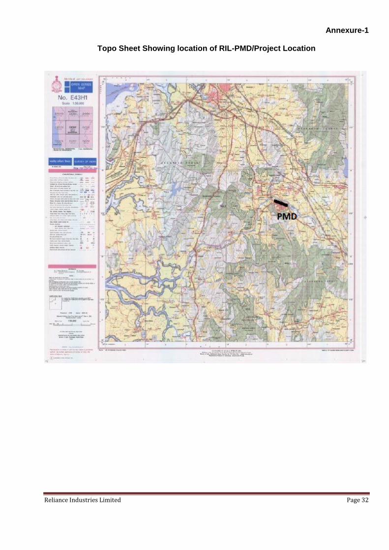
The proposed project will be located within the existing complex at PMD at Mohapada Village, Kalapur Tehsil, Raigad District, Maharashtra. PMD is located within MIDC notified Industrial area and is well connected by rail and road network. Nearest railway station Apta which is around 3 km. west of the site and Mumbai-Pune National Highway (NH-4) is around 2.5 km. North-East of the site. Patalganga river flows about 500 meters north of the site. The proposed project location site is well connected by rail and road and the site is at a distance of around 90 km. from Mumbai. Overall climate is equable with average rainfall of 3000 mm per year and very few days of extreme temperatures. The mean annual temperature ranges from 30oC to 33oC. The mean maximum temperature of the hottest month in this area varies from 30oC-40oC in April-May while mean minimum temperature of coldest month varies from 10oC to 20oC. Extremes of temperatures, like 44oC-45oC in summer and 10oC -14oC in winter, may be experienced for a day or two in respective season. The area has humid climate. Relative humidity varies from 25% to 85%. Driest days being in winter and wettest ones are experienced in July. The rainy season is mostly confined to southwest monsoon and is the source of fresh water supply. PMD location is as given below; the topo sheet showing the project location is attached as Annexure 1

Reliance Industries Limited Page 6
Location of Proposed Project Site 2.3. Debottlenecking Proposal
PTA Debottlenecking: The following modifications are being proposed which will increase the PTA production from 25000 MT per month to 27500 MT per month.
Installation of more energy efficient process air compressor train to use all surplus
steam generated.
Improving process heat recovery from oxidation reactor overhead system.
Installation of azeotropic distillation column.
Installation of additional high pressure crystallizer.
Installation of catalyst recovery unit.
Replacing conventional two stage product separation with single stage rotary pressure
filter.
LAB Debottlenecking: The following modifications are being proposed which will increase the LAB production from 8340 MT per month to 11000 MT per month.
Replacing hazardous HF catalyst-based process with ionic liquid catalyst-based
process developed in-house.

Reliance Industries Limited Page 7
Replacing existing mixer-settler based reactor with new reactor system.
Installing Transalkylation process to convert low value by-product to LAB.
This will also lead to increase in by-products quantity from 51598 MT per month to 75000 MT per month.
The above mentioned proposed debottlenecking at PTA plant is a process envisaged for energy/material recovery, energy conservation, and efficient energy utilization schemes. Similarly, the debottlenecking at LAB plant is for replacing hazardous chemicals, converting low value by-product and efficient energy utilization, both these proposals will not result in any increase in the liquid or gaseous emissions from PMD. The product slate at PMD along with the proposed debottlenecking is given below;
Product Existing Capacity (MT / M)
Post Debottlenecking
Capacity (MT /M)
LINEAR ALKYL BENZENE (LAB) 8,340 11,000
Normal paraffin ( normal grade)
51,598 75,000
Normal paraffin (heartcut grade)
Heavy normal paraffin
Light normal paraffin
Tar polymer
Heavy alkylate 840 840
Light Ends 1110 1110
PURE TEREPTHALIC ACID (PTA) 25,000 27,500
Paraxylene 20,840 20,840
Iso pentane 1,042 1,042
Normal pentane
IG benzene
50,509 50,509 Remax-1
Renine
Liquefied petroleum gases (LPG) (sr grade)
2,250 2,250
2.3 The Process Description
The raw material Naphtha is used to produce Paraxylene an intermediate product. Terephthalic acid (TA) is produced by the oxidation of paraxylene in the presence of Acetic acid solvent with catalysts, in the presence of air. The following section describes in brief the paraxylene process followed by the PTA and LAB processes.
The Para xylene process is divided into the following major sections;
Naphtha pre-fractionation section
Naphtha hydro-treating section
Platforming section
Continuous catalyst regeneration section

Reliance Industries Limited Page 8
Xylene fractionation section
Parex section
Isomar section
Tatoray section
LPG Recovery
A brief description of the above process in given below;
Naphtha Pre-fractionation Section: Feedstock to the paraxylene process is a narrow cut Naphtha of 100 - 140 Deg C boiling range from refineries. Since refinery is supplying straight run naphtha of boiling range 90-160 Deg C, this Naphtha is fractionated in Prefractionation unit for the narrow cut.
Naphtha Hydro-treating: The Naphtha Hydro-treating process is a catalysts reforming process employing a select catalyst and Hydrogen rich gas stream to decompose organic sulphur, oxygen and nitrogen compounds contained in hydrocarbon fractions. In addition hydro-treating removes organo-metallic compounds and saturated olefinic compounds. Hydro-treating processing is commonly used to remove platforming catalyst poisons from heart cut Naphtha prior to charging to the platforming process unit.
Platforming Section: The hydro-treated naphtha from NHT unit is the feed to the
Platforming Section.
Major reactions taking place in the Platforming unit are as follows;
o Dehydrogenation of Naphthenes to aromatics-endothermic, promoted by metal function of catalyst favoured by high reaction temp. and low pressure
o Hydrocracking of paraffins-consumes hydrogen, exothermic, severe hydrocracking reduces liquid yield
o Isomerisation: Midly exothermic, products subject to further reaction to form aromatics or smaller paraffins.
o Dehydrocyclisation of paraffins to naphthenes: This reaction will precede the dehydrogenation of naphthene to aromatics.
Continuous Catalyst Regeneration Section (CCR): The Catalyst Regeneration Section of a UOP Platforming Unit allows the refiner to operate the reaction section at high severities with increased on-stream time by continuously regenerating a circulating stream of catalyst from the Platforming reactors. During a normal operating cycle, reforming catalyst deactivates due to permanent and operating procedures, permanent poisoning can be avoided. The Regeneration section continuously burns off the coke deposit and restores activity, selectivity and stability to essentially fresh catalyst levels.
Xylene Fractionation Unit: This unit consist of two distillation columns. The function of the unit to prepare feed stocks for Parex and Tatoray urllts. The feed from the platforming unit de-heptaniser is prepared in the xylene fractionation unit clay towers. It combines with the clay treated feed from the bottom of BT splitter column located in Tatoray unit and flows to the Xylene rerun column. In day treated product from the isomar unit is also fed to the xylene rerun column. The function of the xylene rerun column is to separate C8 aromatics from the heavier

Reliance Industries Limited Page 9
material in the feed. The C8 aromatics are taken as the overhead product and sent to the Parex feed. The net bottoms product from the xylene rerun column is taken off on flow control upstream of the reboiler pumps and sent to the Tatoray heavy feed rerun column. Tatoray heavy feed rerun column separates C9 aromatics for tatoray unit as overhead product.
Parex Section: The UOP Parex process is a well-established, commercially proven adsorptive separation method for the recovery of high purity para-Xylene from C8 Aromatic fractions obtained from the overhead of xylene rerun column. This uses a solid adsorbent, a zeolitic material of 20-30 mesh size, a liquid desorbent, paradiethyl benzene and a flow directing device called, the “Coplanar Manifolding Indexer” or CMI. Selective adsorption of para-Xylene is effected according to the UOP Sorbex separation technology to produce para-Xylene with a purity of 99. 7%. The process can economically recover 95-97% of the para-Xylene in a single pass.
Isomar Section: lsomar unit is to convert Metaxylene and Ethyl Benzene to para-Xylenes and orthoxylenes. Isomar is a catalyst isomerization process to efficiently convert mixture of C8 aromatics to a near equilibrium mixture. It employs a Bi-functional noble metal spherical catalyst containing both add sites (zeolite) and metal sites (Platinum) which operates in a pressure and temperature range that favours para-Xylene and ortho-Xylene production from Metaxylene and Ethyl benzene. In this process slight amount of Toluene is also produced. However, the isomerisation is then subjected to fractionation to remove light ends (C7) at the top. The bottom product which in rich in paraxylene is recycled back to xylene fractionation unit for recovery of para-Xylene in Parax Unit.
Tatoray Section: The tatoray process is a catalytic process for trans-alkylation of aromatics. In its simplest form, toluene is converted to Benzene and mixed xylene. In actual operations, toluene and mixed C9 aromatics can be converted to C6, C8 and C 10 at aromatics. The Tatoray unit has a fixed catalyst bed reactor where the trans-alkylation reaction takes place. The Tatoray reactor is a simple down flow type, it has an inlet distributor through which reactor feed is directed and the effluent exists through an outlet basket placed at the bottom port. Reactor temperature is the principle variable control conversion. Products arc then separated through a series of distillation columns.
LPG Recovery Unit: The LPG plant essentially consists of five major sections,
o Feed gas mixing section
o Compressor section
o Distillation column section
o Mounded bullets LPG (tanker) loading gantry
Odourization of the LPG: As standard practice, all LP gases shall be odorized prior to delivery to bulk plant by addition of a warning agent of such character that the gases are detectable, by distinct odor to a concentration in air of not over one fifth the lower Iimit of flammability.

Reliance Industries Limited Page 10
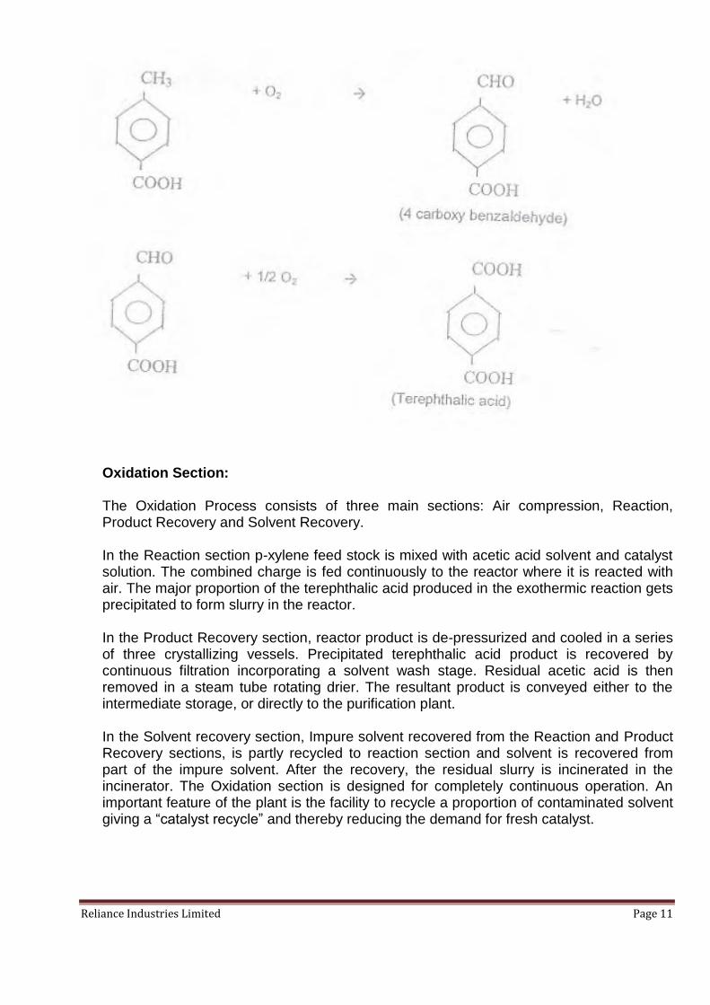
Purified Terephthalic Acid (PTA) Purified Terephthalic Acid (PTA) is produced from, para-xylene in 2 stages;
Oxidation Section
Purification Section The main reactions that take place in the reactor to produce TA are a series of reactions which are given below:
Reliance Industries Limited Page 11
Oxidation Section:
The Oxidation Process consists of three main sections: Air compression, Reaction, Product Recovery and Solvent Recovery.
In the Reaction section p-xylene feed stock is mixed with acetic acid solvent and catalyst solution. The combined charge is fed continuously to the reactor where it is reacted with air. The major proportion of the terephthalic acid produced in the exothermic reaction gets precipitated to form slurry in the reactor.
In the Product Recovery section, reactor product is de-pressurized and cooled in a series of three crystallizing vessels. Precipitated terephthalic acid product is recovered by continuous filtration incorporating a solvent wash stage. Residual acetic acid is then removed in a steam tube rotating drier. The resultant product is conveyed either to the intermediate storage, or directly to the purification plant.
In the Solvent recovery section, Impure solvent recovered from the Reaction and Product Recovery sections, is partly recycled to reaction section and solvent is recovered from part of the impure solvent. After the recovery, the residual slurry is incinerated in the incinerator. The Oxidation section is designed for completely continuous operation. An important feature of the plant is the facility to recycle a proportion of contaminated solvent giving a “catalyst recycle” and thereby reducing the demand for fresh catalyst.

Reliance Industries Limited Page 12
Purification Section:
The Terephthalic acid (TA) product from the Oxidation section contains a small quantities of impurities which must be removed before the material can be used in the manufacture of polyester. The principal impurity, 4 carboxy benzaldehyde (4CBA), an oxidation intermediate, is hydrogenated to para-toluic acid. The para-toluic acid remains in aqueous solution during the subsequent product recovery stages. This is achieved in the Purification section by selective catalyst hydrogenation of an aqueous solution of TA saturated with hydrogen at elevated temperature and pressure.
The purified terephthalic acid is subsequently crystallized and recovered by employing solid/liquid separation and drying steps.

Reliance Industries Limited Page 13
Linear Alkyl Benzene (LAB) Process The process of manufacture of Normal Paraffin mainly consists of following steps: Pre-fractionation Section: This pre-fractionation section consists of the following two distillation columns:
Stripper Column
Rerun Column
Fresh feed kerosene from storage tank is fed to the Stripper Column where the lighter hydrocarbons are taken overhead. The Stripper Column bottoms are fed the Rerun Column where the kerosene containing C10-C14 normal paraffin is taken overhead. This distillated kerosene is sent to the hydro-treating section. The Stripper Column overheads and the Rerun Column bottoms are returned to storage tanks. The Hydrobon Process – Removal of Impurities from Kerosene: The Kerosene feedstock with a boiling range of 170oC-250oC is mixed with recycle and make up hydrogen, raised to reaction temperature and charged to the reactor section where sulphur, nitrogen, oxygen and other metallic impurities present in the feed are eliminated by the use of UOP’s high activity S-12 Hydrogen catalyst, Olefins if present in the feed, are saturated. The presence of all these impurities would reduce the activity of the Molex molecular sieves. The reactor effluent, after being cooled, passes into a high pressure separator from which recycle hydrogen gas is withdrawn. The liquid stream is fed into a stripping column where C9-hydro carbons are rejected overhead and C10 – bottoms are introduced into the Molex Unit. The Molex Process Extraction of n-Paraffin: In this process n-paraffin are separated from the non-normals by molecular sieves. The operation is carried out in a multi-bed adsorption chamber fitted with a number of access lines, each attached to a distributor within the bed and terminating outside the bed at a rotary distribution valves. The flow arrangement inside the adsorbent chamber simulates a continuous counter current flow of liquid and solid phases, without actual movement of the solid. The Raffinate and extract (n-Paraffin) streams

Reliance Industries Limited Page 14
that leave the sieve chamber are routed through the distributing device to their respective fractionation columns where the de-sorbent, Raffinate and extract stream are separated. n-Paraffin Prefractionation Unit: The N-paraffin stream from the Molex Units further pre-fractionated to obtain the heart cut paraffin prior to feeding the Pacol Unit. This section comprises a Stripper and a Rerun Column for removal of lighters (Stripper overhead) and heaviers (Rerun Bottoms). The Rerun overhead (heart-cut) is then fed to the Pacol Unit. The Pacol Process Dehydrogenation of n-Paraffin: The fresh and (recycle the detergent alkylation unit) nC10 to nC13 paraffin are charged to the Pacol reaction section along with recycle hydrogen. The reactor effluent is charged to a low pressure separator from which recycle plus a small quantity of net hydrogen is withdrawn. The liquid phase from the separator is fed to a stripping column. This column serves to remove traces of dissolved gases and cracked products from the alkylation unit feed. Detergent Alkylation Process: The mixture of C10-C13 n-Paraffin, olefins and fresh benzene are combined with recycle benzene and fed to a two stage reactor section. The reactor effluent passes to separating drums where the acid settle out and is returned to the reactor. A small drag stream is charged to the HF regenerator from the first stage separating drum. The regenerator bottoms consisting of very small quantity of polymer is withdrawn from the bottom of the HF regenerator. The hydrocarbon layer from second setting drum is heated and charged to the HF stripper. The stripper vapors are combined with the regenerator vapors, then condensed and recycled to the reactor. The excess benzene is recycled to the reactor section. The overhead paraffin are recycled to the dehydrogenation unit. The bottoms flow to the Rerun and Recovery columns, in which the finished LAB is taken as an overhead cut and heavy alkylate is taken at bottom.

Reliance Industries Limited Page 15
2.4 Captive Co-generation Power Plant (CCPP)
The requirement of steam and power for the process plant can be met by installing high pressure boilers of suitable capacity. The concept of total energy envisages production of one of the requirements e.g. steam as main condition while power generation follows. In this situation, the steam demand is proposed to be met by Three (3) high pressure coal/pet coke fired boilers each having a capacity of 250 TPH. This combination can be used adequately to meet steam as well as power requirement. Normally, 2 boilers and 3 STGs will be in operation and Third boiler will be in standby mode. The steam parameters at superheater outlet have been considered as 110 atm, 515oC in conformity with the steam pressure level existing in the steam system. The power would be produced in 2x50 MW and 1 x 24 MW extraction/ condensing steam turbine generator. The technical features of the proposed CCPP are enclosed as Annexure 2.

Reliance Industries Limited Page 16
SECTION – 3
PLANT INFRASTRUCTURE & BASIC REQUIREMENTS
3.1 INTRODUCTION
The basic requirements for this proposal of debottlenecking as well as the expansion of the CCPP are availability of fuel, water, land and other facilities like road, railhead and transmission system for power evacuation. The debottlenecking proposal does not envisage any additional infrastructure facility except augmented power. This section discusses the requirements, vis-à-vis their availability at the proposed power station site. The Coal / Petcoke based CCPP will have capacity 2x50 MW and 1x24 MW; necessary infrastructural facilities for the project will be added. Necessary space provision for augmentation of auxiliary plant and infrastructural facilities has been considered in the layout. The proposed plant will be located within PMD. The water demand of the project shall be made available at plant boundary by water allocated to PMD by MIDC and the Coal / Pet coke requirement would be met by indigenous or imported sources. The power required for construction will be made available by State Grid. The start–up and stabilization fuels will be natural gas.
3.2 LAND
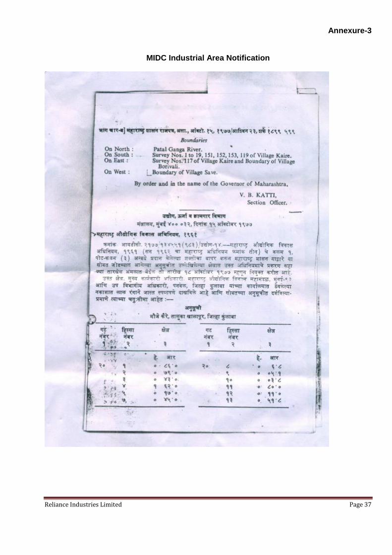
The PMD is located within the MIDC allocated area of around 65.6 hectare. The proposed debottlenecking shall be within the allocated land of MIDC. The MIDC industrial area notification is attached at Annexure-3. The proposed expansion of CCPP will be setup within PMD. There is space for CCPP inclusive of space requirements for temporary storage yard as well. Other areas includes land requirement of roads, drains / trenches, parking, transmission corridor, are already available in the existing process plants. Suitable space for locating the Coal / Petcoke based Cogeneration Plant was examined considering the following:
Clear space availability.
Logistics for Coal / Petcoke supply by trucks from Dharamtar Port
Logistics for Ash disposal
Distance of steam user
Power evacuation
Coal / Petcoke storage area is away from process plants to avoid coal dust pollution.and maintaining safe distance from flare
The overall PMD layout is enclosed as Annexure – 4
3.3 WATER AVAILABILITY & REQUIREMENT
PMD has water allocation of 18960 m3/day from MIDC. This allocated quantity of water from MIDC will suffice the requirement of the proposed project too. The major requirement for water is in the CCPP which is for Cooling water, make-up water for DM plant and other miscellaneous services such as fire-fighting and potable water within plant. The estimated DM water recruitment and cooling tower make up is 1968 m3/day and 13200 m3/day for CCPP. The consumptive water requirement on the basis of semi-open recirculating cooling water system using Induced draft cooling towers.

Reliance Industries Limited Page 17
3.4 RAW MATERIAL REQUIREMENT, AVAILABILITY & TRANSPORTATION
The raw materials for the PMD is heavy Naphtha / Reformate and Kerosene. These raw material are pumped from BPCL / HPCL Refinery at Chembur to PMD through dedicated pipeline. The required quantity is extracted from Naphtha and Kerosene and the rest is pumped back to the Chembur refinery. The existing quantity at the PTA and LAB plant is given below; there is no additional raw material required for this proposal as this only a debottlenecking activity and only modifications in the processes in involved as mentioned in the earlier chapter.
Raw material Quantity (MT / month)
Naphtha 75,000
Kerosene 60,003
The proposed expansion of CCPP will involve Coal / Pet coke for Dharamtar Port near Alibaug is proposed to be used for unloading and onwards movement of Coal / Petcoke by trucks for transferring to PMD. It is estimated that about 87 TPH coal needs to be required for the total power plant 2x50 MW and 1 x24 MW units. Natural gas will be used only for cold start. The annual Coal / Petcoke requirement for CCPP is 0.74 Million Tons / 0.47 Million Tons. The fuel would be pre-crushed at supply end to (-) 250 mm. The daily coal requirement with 100% PLF works out to about 2089 MT for the capacity of 2 x 50 MW and 1 x 24 MW STGs. The limestone requirement for control of SO2 emission when pet coke is used in the proposed CCPP shall be 0.23 MTPA max. The fuel analysis is given below;
Heating Values (kcal/kg)
Pet Coke Coal
LHV 7672 4504
HHV 7895 4774
Ultimate Analysis (weight %)
Moisture 5 25
Ash 0.2 15
Carbon 80.07 51.45
Hydrogen 3.71 3.18
Nitrogen 1.37 1.04
Chlorine 0.63 0.01
Sulfur 7.33 0.7
Oxygen 1.69 12.89
Total 100 100
Proximate Analysis (weight %)
Moisture 5 25
Ash 0.2 15

Reliance Industries Limited Page 18
Volatile Matter 14.22 17.80
Fixed Carbon 80.58 51.42
Total 100 100
3.5 POWER EVACUATION
Power generated from CCPP is evacuated through the power plant 22 kV switchgear. Seven (7) number feeders each for evacuating 25 MW of power are contemplated with contingency consideration of non-availability of one feeder out of seven. These feeder shall be overground cable feeders to interconnect CCPP with process plants. Power also be evacuated to other Reliance Facilities located elsewhere through State and Interstate grid network.
3.6 INFRASTRUCTURAL FACILITIES
All other infrastructural facilities essential for successful implementation of the project in a shorter time frame are available. The existing access roads within PMD will suffice the requirements of this proposed debottlenecking as well as CCPP. Skilled and unskilled manpower will be required during construction and operation, adequate accommodation will be provided to the manpower during construction period of CCPP. Efforts will be made to employ local manpower based on skill set available. Coal/pet coke will be transported by truck to the site using the available road connectivity, Power required during construction will be drawn from the existing sub-station of existing facility. Construction water would be supplied from existing water sources. Other facilities such as Communication viz. telephone, fax, email and other communication facilities etc. will be developed at an early stage for timely implementation of the project.
Reliance Industries Limited Page 19
SECTION – 4
ENVIRONMENT ASPECTS
4.1 INTRODUCTION
The debottlenecking of the above mentioned plant shall not add any additional environmental load in the region. The proposed expansion of the CCPP will be equipped with state-of-the-art pollution control devices to bring down the emission of pollutants to a level well within acceptable norms of the country. The proposed CCPP will have the CFBC technology which uses lime injection for reduction of SO2 emissions. This CFBC technology will also result is low NOX emission and the adequate control mechanisms are in place to control the PM emission which will be kept within statutory limits at all time.
4.2 ENVIRONMENTAL FACTOR
Air Emissions The expected air emissions from a petrochemical complex are PM, SO2, NOx and hydrocarbons (HCs/VOCs). Out of which, PM, SO2, and NOx are emitted continuously from stacks (point sources) associated with fuel combustion as well as process units. Besides small quantities of CO and HC will be released from process stacks. The area sources of hydrocarbons release are through evaporation losses from storage tanks and uncontrolled escapes from process units (fugitive emissions) i.e. by process vents, leakages from pumps, valves and also from incidental spillages. Apart from impact due to point and fugitive sources, In addition there could be air environment impact project related activities at the project-site due to movement of vehicles and construction. Therefore, the major air emission from this proposed project are as follows;
- Dust due to construction activities and flue gas from boiler - Gaseous pollutants from in flue gas - Fugitive emission due to handling of coal & Ash
There will not be any additional stack due to this debottlenecking project. However, the expansion of CCPP will envisage a new stack of 110 m height to disperse the emissions adequately
Dust Particulates in Flue Gas The electrostatic precipitators (ESP) proposed to be installed in this project would be designed to limit the emission level of the particulate matter to 50 mg /m3
Sulphur Dioxide (SO2) in Flue Gas Sulphur Dioxide from CCPP will be controlled through in situ Lime injection. A single (1) multi-flue chimney of 110 m height is envisaged for the proposed power plant to meet the dispersion of the emission adequately to meet requirement of AAQ norms.
Nitrogen Oxides (NOx) in Flue Gas With the implementation of CFBC technology and low NOx burners the combustion occurs in a multistage process due to which the temperature is lower consequently reducing the NOx emissions.

Reliance Industries Limited Page 20
Coal Dust due to Handling of Coal Coal dust is likely to be generated at the conveyor transfer points, pet coke & coal unloading area and fuel stockpile area. All these locations would be provided with dust suppression facilities. Further, all conveyors would be provided with enclosed galleries. The bottom portion of all the conveyor galleries would be provided with seal plates
Noise:
The major source of noise generation at shall be from process plants, CCPP, etc, In the proposed debottlenecking there is no increase in noise level is anticipated. In proposed expansion of CCPP proper precaution will be taken to keep noise level within prescribed limits. From design of equipment to installation. The STG and other major noisy equipment’s will be provided enclosure for noise attenuation to reduce noise level to 85 d B(A) at 1M distance.
Presently, at RIL-PMD the Noise levels are checked monthly during day time and night time around the RIL-PMD Complex. The Noise levels are well within the prescribed limits. The below schematic provides the noise monitoring locations;
Noise monitoring locations at RIL-PMD complex
Solid Waste Disposal:
The proposed debottlenecking proposal shall not generate any additional solid waste including hazardous wastes. However, the proposed expansion of CCPP using coal/pet coke will generate ash. The coal which shall be used for this proposed expansion will contain a maximum of 15% ash. The pet coke which shall be used for proposed expansion will contain 0.2% ash. The Bed Ash of ~ 5.8 T/hr and the Fly Ash of ~ 23.2 T/Hr from the boiler is expected and it will be taken to the ash disposal silos of adequate capacity. The ash will be

Reliance Industries Limited Page 21
utilized in construction & cement manufacture as per Ash utilization notification of MoEF. The hazardous waste such as spent oil will be sent to authorize recyclers and waste such as domestic waste comprising office waste shall be disposed of as per prevailing practice adhering to MSW rules.
Water Pollution:
The proposed debottlenecking project shall not contribute to increase in effluents from the complex. The present effluents are 5177 M3 / day is treated and disposed to CETP of MIDC for further disposal to Dharamtar Creek along with other industries effluents. The effluents from CCPP are mainly; - DM blow down water of ~ 4.1 m3/hr, -Cooling tower blow down water of ~ 92 m3/hr, - Boiler blow down water of ~1.25 m3/hr. (to be used for CT make up) These wastewater shall be treated in an proposed RO system and will be re-used. No additional sewage generation is expected from the project except during construction, which will be treated in the existing ETP along with operating plant effluents as approved by MPCB. The following description provides the details of the existing wastewater treatment facility at RIL-PMD complex.
PTA Plant The treatment consists of the following stages of operations:
Equalization
Anaerobic Treatment
Aerobic treatment Equalization: The effluent flow can vary in terms of both quality and quantity. To ensure that treatment system operates at fairly steady condition, an equalization tank has been provided to balance the flows from various sections of the plants in the PTA Division. The equalization tanks are provided with an array of aeration grids and a common blower. Air is blown through these to keep the tank contents in a homogeneous state. After homogenization in the first compartment, the mixed effluent flows in the next compartment where it is mixed with sewage. From here the effluent flows for Anaerobic and Aerobic treatment. Anaerobic Treatment: The term “anaerobic treatment” implies a treatment process that is carried out without oxygen. Anaerobic digestion (or fermentation) of organic matter is carried out by a special mixed group of anaerobic microorganisms (bacteria). During the treatment process, these microorganisms utilize the organic matter contained in the raw waste water as a source of food and energy. As a result of their normal growth cycle, the micro-organisms convert organic matter to a gaseous by- product called biogas and a small amount of new cell mass. In general terms, anaerobic digestion may be viewed as a three step process involving:
Hydrolysis
Acid formation
Methane formation. During the hydrolysis the insoluble organic matter is made soluble. Hydrolysis is carried out by enzymes secreted from the micro-organisms (i.e. extra cellular enzymes) and

Reliance Industries Limited Page 22
enzymes released from the micro-organisms upon death (i.e. intracellular enzymes). These enzymes dissolve solid organic waste water particles so that bacteria can use them as food. After the organic matter is made soluble, it becomes available as food for the micro-organism in the next step. The second step in anaerobic digestion is acid formation. Here , the soluble complex organic ( i.e. cellulose , starches , proteins , fats and carbohydrates) is broken down bio chemically into less complex organic matter ( i.e. sugars , amino acids and long – chain volatile acids). These intermediate products are subsequently broken down further into simple organic matter (i.e. short chain volatile acids- mainly acetic acid and propionic acids). The micro-organisms which accomplish this breakdown of organic matter to volatile acids are known as acid formers or acidogens. The third step in anaerobic digestion is methane formation, which is carried out by anaerobic microorganisms known as methane or methanogens. The methane formers convert the volatile acids produced in the formation step into mainly methane (CH4) and carbon dioxide (CO2). The methanogens depend upon the acidogens to supply volatile acids so that they may produce CH4 and CO2 (i.e. bio-gas). The anaerobic digestion steps occur simultaneously in the reactor as the acidogens and methanogens exist as a mixed population in the reactor, environmental conditions for the most efficient operation must be favourable to both. When balanced biological activity exists between the acidigens and methanogens, the volatile acids produced during the acid formation step are converted as rapidly as they are produced into biogas. Aerobic system: The aerobic system consists of a two stage biological treatment. The waste water from anaerobic treatment is routed through v-notch flow to first stage aeration tank, where part of the suspended solids, dissolved organic solids etc. are subjected to biological treatment by Activated Sludge Process. Aeration tank –I has been provided with 4 nos. surface aerators and Diffusers. The surface aerators and diffused aeration ensure that the biomass in the tank remains in suspension and is uniformly distributed throughout the tank volume for optimum stabilization of the effluent. Provision is made for the addition of nutrients like urea and Di-ammonium phosphate which are required to ensure healthy growth of the microbial mass in Aeration tank- I & II. The wastewater overflowing from aeration tank-I is in partially stablised form. It contains flocs of bio-mass that have to be separated. This is done in Secondary Clarifier –I. Part of the Clarifier-I under- flow is pumped through the sludge conditioning tank and thickener for the final disposal on sludge drying beds after de- watering through belt press filter. The clarifier –I overflow passes to the second stage aeration tank-II along with the overflow from Anaerobic System.
The Aeration tank-II is also provided with 3 surface aerators and Diffusers. The wastewater overflowing from aeration tank-II is in a stabilized form. It contains floc and bio-mass which are separated in Secondary clarifier-II . Part of the clarifier –II under flow is pumped back to aeration tank-II as seed material. The excess sludge is pumped through sludge conditioning tank and thickener for final disposal on sludge drying beds after de-watering through belt press filter. The Clarifier –II overflow passes to the effluent sump where boiler blow down, cooling tower blow down and DM plant regeneration waste water are also discharged. The tank is also provided with a polishing surface aerator to increase the residual oxygen level of the treated effluent before discharge into the Common Effluent Treatment Plant.
Reliance Industries Limited Page 23
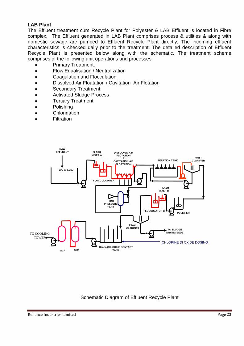
LAB Plant
The Effluent treatment cum Recycle Plant for Polyester & LAB Effluent is located in Fibre complex. The Effluent generated in LAB Plant comprises process & utilities & along with domestic sewage are pumped to Effluent Recycle Plant directly. The incoming effluent characteristics is checked daily prior to the treatment. The detailed description of Effluent Recycle Plant is presented below along with the schematic. The treatment scheme comprises of the following unit operations and processes.
Primary Treatment:
Flow Equalisation / Neutralization
Coagulation and Flocculation
Dissolved Air Floatation / Cavitation Air Flotation
Secondary Treatment:
Activated Sludge Process
Tertiary Treatment
Polishing
Chlorination
Filtration
Schematic Diagram of Effluent Recycle Plant
TO COOLING
TOWER
DMF
Ozone/CHLORINE CONTACT
TANK
TO SLUDGE
DRYING BEDS
FINAL
CLARIFIER
AERATION TANK
DISSOLVED AIR FLOTATION
& CAVITATION AIR
FLOATATION
FLASH
MIXER A
HOLD TANK
RAW
EFFLUENT
ACF
FLASH
MIXER B
FLOCCULATOR A
FLOCCULATOR B
HIGH PRESSURE
TANK
POLISHER
FIRST
CLARIFIER
CHLORINE DI OXIDE DOSING

Reliance Industries Limited Page 24
Primary Treatment
a) Flow Equalization: Raw effluent is first collected in a Holding Tank to make the effluent characteristics homogeneous. Air blowers ensure proper equalization of the effluent in the Holding Tank. Alkali (NaOH) is dosed in the holding tank to neutralise the effluent. A pH indicator, flow transmitter and controller interlocked with alkali dosing pumps are provided for automatic pH control.
b) Coagulation and Flocculation: Effluent from the Holding Tank is pumped to the Flash Mixer cum Flocculator A. Alum and Polyelectrolyte is dosed for coagulation and flocculation of the colloidal impurities and for de-emulsification of emulsified oils in the Flash Mixer. A screen type mechanical agitator is provided to ensure uniform mixing in the Flocculator Tank.
c) Dissolved Air Floatation (DAF): Effluent from the Flocculation tank overflows into the DAF system. This system is designed to remove the oil and suspended solids from the effluent. In this system the dispersion water, the water in which air is dissolved at high pressure, is released at atmospheric pressure at the inlet of floatation tank so the air comes out of the solution in the form of small bubbles which attaches themselves to the particles in the effluent and carry them to the surface. Dispersion water is obtained by pumping water from the level tank through a high pressure pump to an ejector where water is mixed with air supplied by a compressor. Any solids in the water which fall to the bottom of the tank can be removed through a drain valve. Scrapers are situated on top of the floatation tank to remove the solids floating on the liquid surface. The clear liquid passes through a central pipe, into the Aeration Tank.
Secondary Treatment- Activated Sludge Process (ASP): Aeration Tank and Secondary Clarifier together constitute the Activated Sludge Process. This process is a continuously mixed reactor (CSTR) - a biological treatment system characterized by a suspension of aerobic micro-organisms, maintained in a relatively homogeneous state. The overflow from the DAF enters the Aeration Tank. Aeration Tank uses mechanical surface aerators (five in no., 50 HP each) which induce O2 transfer from the air to the effluent and at the same time maintain the aerobic bacterial culture in suspension. The Aeration tank also has an online Dissolved Oxygen Meter (DO meter). From the Aeration Tank the effluent enters the Secondary Clarifier. The sludge is removed periodically (blow down) once in a day and sent for drying. While the clarified outlet goes for tertiary treatment, the bottom sludge is continuously under recirculation to maintain desired MLSS (Mixed Liquor Suspended Solids) in the aeration tanks.
Tertiary Treatment
Polishing: The clear overflow from secondary clarifier is collected in a polishing tank, from where it is pumped to flash mixer B. In flash mixer again Alum and Polyelectrolyte (PE) is dosed into the water. The Flash Mixer B is connected to Flocculator B. The effluent from flocculation tank flows into the Final Clarifier. The sludge generated is separated in the Final Clarifier.
Chlorination: The clear overflow from clarifier flows to a Chlorine Contact Tank ( CCT). Chlorine is bubbled in the mixing chamber of Chlorine contact tank for disinfection and

Reliance Industries Limited Page 25
chemical oxidation of organics. The construction of CCT is such that it increases chlorine contact time. At the end of Chlorination Tank the residual chlorine in water is maintained below 0.2 ppm. Filtration: After CCT, Filter feed pumps are used to pump the effluent to Dual Media Filter (DMF) followed by Activated Carbon Filter (ACF). Sand and Anthracite are used as the filter media in the DMF. In DMF suspended solids are separated from water. In ACF, activated carbon is used for adsorption of the impurities, especially residual chlorine, oil and grease is removed. The Filter Backwash is recirculated back into the Equalization Tank. The treated effluent is used as make-up water for Cooling Towers and for gardening.
4.4 POST OPERATIONAL MONITORING PROGRAMMEE
Regular monitoring of pollutants in different environmental disciplines like air, water, etc. will be undertaken during the post operational phase of the plant. The monitoring locations will be finalized in consultation with State Pollution Control Board.

Reliance Industries Limited Page 26
SECTION – 5
PROJECT IMPLEMENTATION
5.1 PROJECT IMPLEMENTATION SCHEDULE
Successful execution of the project largely depends on the coordinated approach of the project implementing agencies. Proper co-ordination between the various project execution agencies, monitoring of project schedules, appropriate mobilization of manpower and other resources can achieve effective cost control and timely completion of the project.
The debottlenecking project is expected to be commissioned in 30 Months. The proposed CCPP project would be having capacity of 2x50 MW and 1 x24 MW which is expected to be commissioned within 30 months from the date of award of contract. It is envisaged that the proposed project shall be executed by appointing a consultant for the basic & detailed engineering including technical bid evaluations & the complete Procurement & construction to be done by RIL.
The proposed coal/pet coke based power plant for installation would consist of the following major equipments:- a. Three Steam Generators, along with all ancillaries and auxiliaries, main stack
and all duct work, damper, chimney, suction air filters, silencers etc., along with controls and instrumentation, suitable for base load operation with coal as the main fuel.
b. Three (3) Steam Turbine Generator sets with deaerator & feed heating equipment, steam condenser, CEP and feed water pumps with all piping systems.
c. Other auxiliary systems and major equipment needed for the project:-
Coal/petcoke Handling System.
Ash Handling System.
Cooling Water System.
Fire Fighting Augmentation.
Natural gas System
AC & Ventilation System
Electrical Distribution System
Step-up & Aux. Transformers
Illumination & Inter communication System
Civil construction, mechanical and electrical erection services
5.2 PROJECT SCHEDULE The salient features of the schedule are:-
i) Site preparatory work covering survey, leveling, grading to be completed and construction facilities made available before the start of actual construction.
ii) Civil work including building and equipment foundations are to be completed before the equipment arrives at site.

Reliance Industries Limited Page 27
iii) Completion of Erection & Commissioning activity of the Main Boiler has been indicated as twenty four (24) months after placement of order. Erection of steam turbine would be completed in line with Main Boiler schedule so that, the STG is ready for commissioning along with Main Boiler.
iv) The Civil works of Power Plant Building would be completed within ten (10) months for taking-up the commissioning activities as per schedule. All auxiliary systems such as CHP, AHP, plant water system, CW systems, fire fighting etc., needed for commissioning the plant should be suitably completed so as to match the schedule for initial trial of the main equipment.
5.3 PROJECT MANAGEMENT
It is envisaged that an experienced and well-equipped project management group of the Project Authority would be deployed to overview and steer the project through from inception to commissioning. The team would co-ordinate and controls all the following basic activities:- i) Interfacing with different organizations entrusted with engineering, supply and
erection activities. ii) Procurement activities covering control and monitoring of preparation of
specification, tender evaluation, negotiation, ordering, vendor drawing review etc.
iii) Material Management & Quality Assurance. iv) Supervision of construction and erection activities. v) Preparation of Progress Reports & updating project schedule. vi) Certification of Performance Testing and acceptance in association with
Consultant. Simultaneously, a site office will be established which will co-ordinate the pre project activities during conceptual engineering stage and later on take up supervision and construction management during the construction stage. Basic engineering for the equipment/systems may be carried out by an Engineering Consultants to be appointed by the Project owner.
5.4 PROJECT MONITORING, CO-ORDINATION & CONTROL
5.4.1 Project Monitoring Information System
Progress of each activity at every stage would be physically monitored by respective supervising engineers. All detailed information would be passed on to the Central Monitoring Cell to keep track of the work progress. The detailed PERT / CPM network for the project would be monitored on monthly / fortnightly basis to compare with scheduled progress Vs actual progress achieved at site.
5.4.2 Co-ordination
Regular meetings would be held at site among the representatives of the Contractors, the Consultants and the Engineers of Projects Department to review the progress of each activity. At these meetings, slippages in progress would be identified and corrective measures shall be taken. The problems arising out of site and material constraints would be promptly sorted out. The meetings would also be attended to by

Reliance Industries Limited Page 28
one of the senior executives of the company to facilitate on-the-spot decision. Minutes of meetings would be circulated among all concerned for necessary follow-up action.
Co-ordination meetings between the Consultants and the senior executives of the Project Authority would be held regularly for major decisions in regard to planning, designing of various plant and equipment, execution procedures, manpower deputations, industrial relations, security, etc. Steps would be taken to ensure regular interactions between the Contractor, the Consultants and Projects Department. Experienced site engineers will be working under the site manager at the site office. The computer system set-up will allow close coordination with the home offices, which will also be used for back-up and to solve any upcoming design issue. Owner will organize and supervise construction work on site. Site activities of the subcontractors’ site teams will be coordinated by Owner to ensure that working areas are clearly assigned and safe. Special emphasis will be put on the proper coordination of interfaces between different packages to ensure, that erection and commissioning work runs continuously and smoothly.
5.4.3 Reporting
Various reports would be generated in regard to the physical and financial progress of the project on monthly, quarterly and yearly basis for forwarding to the various Government Departments, Financial Institutions as well as for internal use. Daily progress of the major items of work, along with their weekly/ monthly targets, would be reported to the project head. The progress measurement system and weighting according to various activities will be mutually decided and agreed based on the Consultant’s proposal.
5.4.4 Financial Control
Actual cost records would be regularly monitored against forecasts, which would be forwarded to Finance Department by the Projects Department on monthly, half-yearly and yearly basis, depending on the actual progress of delivery and erection/construction. Fund requirements would be assessed and arranged accordingly.
5.5 OPERATION AND MAINTENANCE PHILOSOPHY
The objectives of plant operation and maintenance shall be to maximize the plant output and availability with safe, reliable and efficient mode of plant operation, meeting all regulatory requirements. Since the plant operation and control shall be achieved by a modern state-of-the-art control and instrumentation system employing DCS MIS, the plant O&M is proposed to be carried out by a limited number of highly qualified and motivated operating staff. To achieve high degree of efficiency in plant management and operation, proper training scheme consisting of in-house training as well as at manufacturer’s work shall be developed during execution stage of the project. Beside, the operators will be trained by the OEM specialists at their shop and at site to develop requisite expertise for operation of the advanced class Boilers & STG in line with OEM recommendation. The O & M staff would be in place during commissioning stage so that they will be associated with the OEM team during pre-commissioning stage of the units. The operation and maintenance of the station would be the overall responsibility of the Plant Chief, who would be assisted by a team of experience Executives and Operators in the respective field. Since the infrastructure for

Reliance Industries Limited Page 29
maintenance of the specialized plant and machinery may not be readily available near site, adequate maintenance facilities for day-to-day and minor plant maintenance including a well-equipped workshop and trained technicians shall be developed for the project. Major maintenance and annual overhaul will be contracted out to manufacturers or reputed agencies. Odd jobs like, plant cleaning, hiring of vehicles, road and drainage maintenance, plant security, gardening / green belt development etc. will be locally contracted out.

Reliance Industries Limited Page 30
SECTION - 6
PROJECT APPROVAL & CLEARANCE
6.1 GENERAL
In order to control and regulate the development of proposed project the legal frame work developed by Government of India shall be followed. Accordingly, several clearances and approvals shall be required to be obtained from different Government and Statutory Agencies at various stages of development and operation at phase of the project. Indicative list of Approvals / clearances to be obtained from Govt. Authorities for this project are as below:
1. Environmental
Ministry of Environment, Forest & Climate Change (MoEF & CC)
2. Consent to Establish Maharashtra Pollution Control Board (MPCB)
3. Boiler Pressure Parts Chief Inspector of Boiler
4. Plant Installation Factory Inspectorate
5. Electrical Installation Electrical Inspectorate
6. Construction Labour Labour Commissioner
7. Fire Fighting Insurance Authority and Local Authority

Reliance Industries Limited Page 31
SECTION - 7
PROJECT COST ESTIMATE
The proposed debottlenecking process will be carried out at a capex of Rs. 340 Crs. for PTA plant and 200 Crs. for LAB plant. The capex for the CCPP is envisaged at Rs. 947 Crs. Therefore, the total Capex envisaged for this proposed project is Rs. 1487 Crs.
Reliance Industries Limited Page 32
Annexure-1
Topo Sheet Showing location of RIL-PMD/Project Location

Reliance Industries Limited Page 33
Annexure-2
Brief Technical Features of 2x50 MW and 1x24 MW Captive Cogen Power Plant (CCPP) at RIL Patalganga and Efficiency improvement of the existing Gas turbines from 24MW to 33MW. Reliance Industries limited intends to put up a coal based 2x50 MW & 1x24 MW Captive Cogeneration Power Plant (CCPP) to cater to the power and process steam requirement of their existing two units of PTA plant and Polyester plant and Efficiency Improvement initiative for existing Gas Turbines (2x 24MW) to increase the power output to 33 MW (Each).These two units of the Petrochemical Plant complex are located at Patalganga near Mumbai. The project shall comprise 3x250 TPH (1W +1S) high pressure boilers and 2x50MW & 1 x 24 MW steam Turbine with associated auxiliary systems such as, condensers, CW system (Cooling Towers, C.W. Pumps, Auxiliary C.W. Pumps), Effluent Treatment Plant (ETP), Electrical Distribution System, Instrumentation & Control system, Inter connection of H.P. steam supply header of STGs, Deaerators, Boiler Feed Water Pumps, ESP, multiflue chimney, Electrical distribution system, Instrumentation & control system, steam supply piping and pipe cum cable rack up to the interconnection of existing process steam header. Other utilities such as DMW, compressed air (I.A. & S.A.), C.W. F.W. (Filtered Water) and water for hydrants of fire protection system shall be tapped from the existing plant. Other utilities such as compressed air (I.A. & S.A.), C.W. F.W. and water for hydrants of fire protection system shall be tapped from the existing plant. The brief technical features of various equipments for Mechanical, Electrical Systems are as follow: 1.0.0 Mechanical
1.1.0 Boilers: CFBC boilers, 3x250 TPH, Each boiler shall be operating at 110.0 kg/cm2g pressure and temperature of 520 +/- 5 degree C at the superheater outlet. Normally these boilers shall be operating on imported coal/ Indian coal. However, these boilers shall be capable of operating on petcoke as well. Various Draught Fans (ID, SA and PA) for the Boilers shall be provided with VFDs. These Fans shall be 2x50% capacity with 20% margin on flow and 44% margin on head for each Boiler. Natural Gas (NG) at 5.0 kg/cm2g shall be provided for the boiler start up and for drying of lime stone. Suitable HP and LP chemical dosing systems shall be provided.
1.2.0 ESP: Particulate matter in flue gas at outlet of each ESP with one field out of service at BMCR shall be </= 50mg/Nm3.
1.3.0 Chimney: One (1) RCC multiflue chimney common for all three boilers in Phase-1. The height of the chimney shall be minimum 110 m considering worst fuel (Petcoke with high sulphur content) as per MOEF norms. Sox level shall be limited to </= 400 ppm and NOx level shall be limited to </= 100 ppm.
1.4.0 De aerators: 2x275 TPH Spray cum tray type. Shell and head of boiler quality material and trays of SS-304 material. Deaerator storage tank shall have minimum 10 minute storage (between maximum and minimum water levels) at BMCR + return condensate

Reliance Industries Limited Page 34
from process plant. De aerators operating temperature is maintained at 150 degree C. Equalizing arms between two De aerators shall be provided on water and steam side.
1.5.0 BFW Pumps with Hydraulic couplings: 3x100% capacity BFW Pumps (1W +2S) in Phase-1 and 1x100% capacity BFW Pump (1W).
1.6.0 Feed Control Stations: 2x100% with 1x30% capacity feed control stations at inlet to the boilers shall be provided.
1.7.0 Process steam parameters at the battery limit are as follow: i) Maximum Flow- 240 TPH at 100 bar(g) and 490 degree C ii) Minimum Flow- 120 TPH at 100 bar(g) and 490 degree C iii) Maximum Temperature- 510 degree C
1.8.0 Fire Detection and Protection system-
i) Water for Fire protection system for Boilers area as well as for STG area shall be tapped from the existing fire hydrant system. Suitable fire detection system for Boiler area as well as for STG area shall be provided.
ii) Independent fire detection and protection system for coal stockyard area shall be
provided consisting of Fire Water cum Raw water storage Tank, Motor operated and diesel engine operated Fire water Pumps, Jockey Pumps, Fire hydrants and Fire detection system.
1.14.0 Condensate Polishing Unit (CPU): CPU shall be added to treat hot and cold process condensate return from the process plant. This unit shall consist 1 (one) Condensate Storage Tank (180 m3 capacity), Plate type heat exchangers, CPU and condensate transfer pumps.
1.15.0 Steam Turbine Generators & Auxiliary systems
i) 1x 24 MW & 2x50 MW Steam Turbines shall be of single casing, horizontal, extraction cum condensing type, operating on fixed pressure mode of operation.
ii) Turbine oil cooling system shall be provided. iii) Turbine oil purification system shall be provided. It shall consist of one no.
centrifuge, 2x100% lube oil pumps, Lube oil tank & piping of SS construction and Duplex type SS oil filters.
1.16.0 Steam Condenser-Horizontal water cooled shell & tube type two pass condenser with
2 minutes hot well storage capacity and condenser exhaust pressure of 76mm Hg shall be provided with Condenser shell of boiler quality plates and Tubes of SS -304.
1.17.0 Condenser air extraction system consisting of 2x100% steam air ejectors and 1x100% Hogging ejector shall be provided.
1.18.0 Condensate extraction Pumps-2x100% pumps per unit, vertical, mixed flow, centrifugal design, can type with mechanical sealing arrangement shall be provided. Capacity shall be based on maximum steam flow at turbine exhaust during VWO operation and drains with 3% makeup and 10% margin.
1.19.0 LP Feed Water Heaters-2nos. LP feed water heaters (shell & tube type) for each unit with C.S. Shell and SS -304 Tubes shall be provided.

Reliance Industries Limited Page 35
1.20.0 HP Feed Water Heaters have not been envisaged since BFW Pumps are located quite
far away (~ 500m away) in the Boilers area.
1.21.0 Cooling Tower (CT): One Induced draft, counter flow type, Cooling Tower shall be provided, common for two units. The Cooling Tower shall have Six (6) cells (with back to back arrangement), with a range of 9.0 degree C and approach of 4.5 degree C. The Cooling Tower shall be provided along with suitable flow control valve in the inlet make up water line and level switches in the CT basin.
1.22.0 CW and ACW Pumps and piping: Five (5) CW pumps (4W + 1S) and three (3) ACW Pumps (2W +1S) shall be provided for both units along with the buried CW piping system.
1.23.0 Side Stream Filters (SSFs): Two (2) (1W +1S) SSFs shall be provided, each sized for 3% of Total CW and ACW flow.
1.24.0 Potable water system: Three (3) Sintax Tanks each of 5 m3 capacity shall be provided one each in STG area, Boiler area and in Coal Stockyard area - along with the distribution piping.
1.25.0 Existing Gas Turbines are site rated to 24MW capacity based on the de-rating of Gas turbines to local Ambient Conditions and Aging/Fouling of the Compressors, by replacing some of the Parts of the Gas turbines and Changing the control System software it is possible to increase the capacity of the Gas turbines from 24MW each to 33 MW each.
2.0.0 Electrical System- 2.1.0 General
Power generated from the 1x24 MW & 2x50 MW units will be hooked up to extended feeders of existing 22kV ENC switchgear. Further evacuation of power will be through existing 22kV feeders from the same switchgear to various process plant equipments. The auxiliary power required for the 1x24 MW & 2x50 MW power plant will be derived from same 22kV ENC switchgear along with necessary step down transformers and associated 6.6kV and 415V switchgears.
2.2.0 Description of Auxiliary Power Distribution:
The generator will be directly coupled to the respective steam turbine and shall have a nominal rating of 24 MW & 50 MW at 0.8 (lag). Generation level shall be 11 kV, 50 Hz, 3 ph. The generator shall be connected to the 22 kV switchgear bus through respective 62* MVA, 11kV/22 kV generator transformer. Connection between generator and generator-transformer low voltage terminal shall be done by segregated phase bus duct and that between the high voltage terminal of Generator Transformer and 22kV switchgear shall be done by H.T Cable. Two voltage levels viz. 6600 volts and 415 volt have been envisaged to supply power to plant auxiliaries. At Powerhouse 6.6kV unit power board is envisaged for supplying the total auxiliary loads of the respective unit of the power plant. This 6.6kV switchboard at power house shall be fed from Existing 22kV ENC Switchgear through two nos. adequately rated 22/6.9kV station transformers. This 6.6kV switchboard shall cater to total auxiliaries of unit like
Reliance Industries Limited Page 36
ID fan, FD fan, BF pump, etc., unit L.T loads, ESP loads, Ash handling plant, through required number of 6.6kV breakers, 6.6/0.433kV transformer & 415V PCC and MCC’s.
The secondary of Station transformer shall be connected to 6.6kV switchgear through 6.6kV (UE) grade cables. And total auxiliary loads for the plant shall be fed from the 6.6 kV switchboards located in Boiler area. 415V PCC shall receive power from the 6.6kV boiler area switchboard through 6.6/0.433 kV LT auxiliary transformers. Different MCCs for the plant LT loads shall be connected with the 415V PCC of the boiler area through cables. A reliable DC power source shall be provided to supply those loads which are required to function for security, protection and safe shutdown of plant in the event of failure of normal AC power supply. Each unit shall have one (1) 110V battery set of adequate capacity for the total DC loads of the unit. 110V D.C. battery and D.C. panels will be provided for the D.C. power supply. And batteries will be NI-Cad type. Normal requirement of the battery is to supply power for the following: Control and monitoring of the plant & Alarm and annunciation of plant condition under emergency. Capacity of the 110 V battery sets will meet the requirement of the total loads. Uninterruptible power supply system of continuous duty have been envisaged to supply regulated, filtered and uninterrupted 110 V, 50 Hz, single phase power within acceptable tolerances to critical AC loads like computerized data acquisition system, microprocessor based control and instrumentation system, control systems, annunciation system, indicators/recorders mounted on unit control boards and other critical loads of such nature. The emergency power system provides power to essential auxiliary loads required to permit a safe shut down of the unit in the event of a plant blackout. In addition, power is provided for auxiliaries and services required for personnel safety and minimum plant maintenance during the blackout. Emergency MCC shall be provided for emergency loads. C Lube Oil Pump, turning gear motor, vapour extractor motor, Charger for DC system and UPS system loads are generally connected to the emergency MCC.
Reliance Industries Limited Page 37
Annexure-3
MIDC Industrial Area Notification

Reliance Industries Limited Page 38

Reliance Industries Limited Page 39

Reliance Industries Limited Page 40

Reliance Industries Limited Page 41
Reliance Industries Limited Page 42
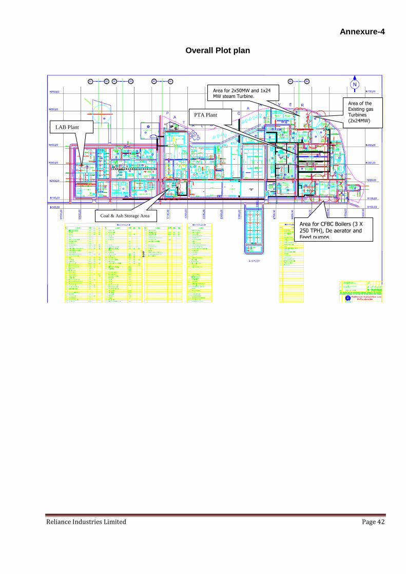
Annexure-4 Overall Plot plan
Coal & Ash Storage Area
Area of the
Existing gas Turbines
(2x24MW)
Area for 2x50MW and 1x24 MW steam Turbine.
Area for CFBC Boilers (3 X 250 TPH), De aerator and Feed pumps
LAB Plant
PTA Plant