pre-con education: recognizing your network's key performance indicators that impact end-user...
TRANSCRIPT
ca Opscenter
Pre-Con Education: Recognizing Your Network's Key Performance Indicators That Impact End-User ExperienceRob Webb
OCX68E #CAWorld
Advisor, Pre-SalesCA Technologies

2 © 2014 CA. ALL RIGHTS RESERVED.
Abstract
Understanding key network metrics that impact end-user experience and how to leverage these key performance indicators is imperative for troubleshooting issues and restoring optimal network performance. In this session, you will learn how to establish fundamental metrics for technology communications, gain an understanding of key concepts attributed to communication processes, gain an understanding of network performance metrics that actually impact end users, understand five sources of network latency and learn to use reference models as a troubleshooting tool.
Rob Webb
CA Technologies
Advisor, Presales

3 © 2014 CA. ALL RIGHTS RESERVED.
Objectives
UNDERSTAND NETWORK METRICS THAT IMPACT END-USER EXPERIENCE
UNDERSTAND FIVE SOURCES OF NETWORK LATENCY
USING REFERENCE MODEL AS A TROUBLESHOOTING TOOL
TCP/IP THROUGHPUT
TCP/IP CONGESTION CONTROLS
1
2
3
4
5

4 © 2014 CA. ALL RIGHTS RESERVED.
Protocol Types
PROTOCOL CONNECTION-ORIENTED? RELIABLE?
Ethernet NO NO
Frame Relay YES NO
ATM YES NO
IP NO NO
UDP NO NO
TCP YES YES
ICMP NO NO

Communication ModelsKPIs–User Impact

6 © 2014 CA. ALL RIGHTS RESERVED.
Communication Models
Client/Server Communications
Terminal/Host Communications
Streaming Communications
Peer-to-Peer

7 © 2014 CA. ALL RIGHTS RESERVED.
Client/Server Model
Distributed Computing
Client software resides on user workstation
– Internet Explorer, Database applications, Proprietary applications, etc.
Server software resides on a server
– An application daemon listening on a service port
Client sends requests to server for various amounts of data
– Tends to create “bursty” traffic patterns
– Less sensitive to changing network conditions
Applications that are sometimes referred to as “Network Friendly”
– Able to capitalize on available bandwidth quickly
– May consume considerable amounts of bandwidth for brief periods
8 © 2014 CA. ALL RIGHTS RESERVED.
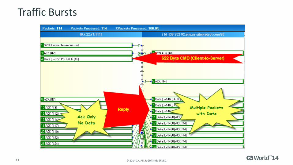
Client/Server Model
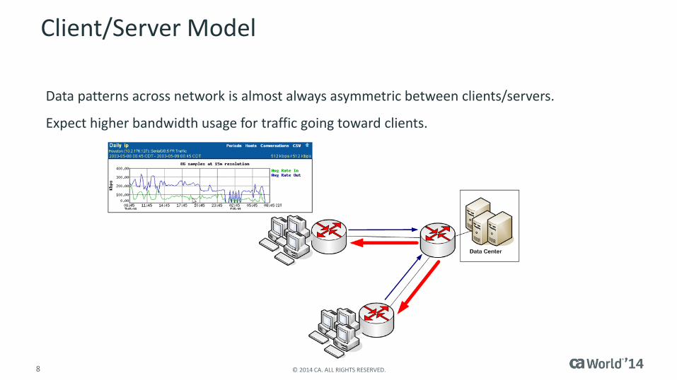
Data patterns across network is almost always asymmetric between clients/servers.
Expect higher bandwidth usage for traffic going toward clients.
9 © 2014 CA. ALL RIGHTS RESERVED.
Client/Server Model
10 © 2014 CA. ALL RIGHTS RESERVED.
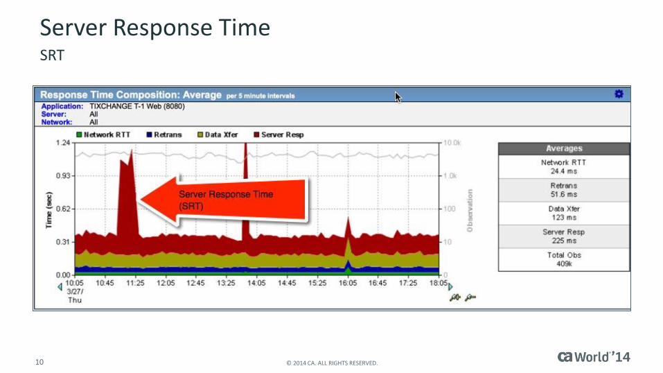
Server Response TimeSRT
11 © 2014 CA. ALL RIGHTS RESERVED.
Traffic Bursts
12 © 2014 CA. ALL RIGHTS RESERVED.
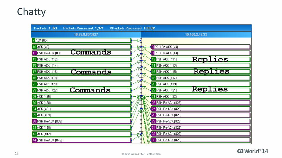
Chatty

13 © 2014 CA. ALL RIGHTS RESERVED.
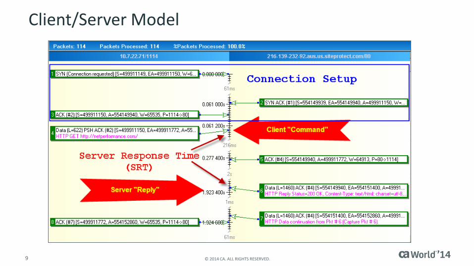
Reply “Timing”
What effects the time it takes to deliver a reply?
Data Transfer Time

14 © 2014 CA. ALL RIGHTS RESERVED.
Application Turns
SRT Observations = Number of Application Turns
A Command/Reply Sequence = 1 Application Turn

Loss, Latency and BandwidthKPIs–User Impact
16 © 2014 CA. ALL RIGHTS RESERVED.
Network Issues
Packet Loss Latency
There are only two things on a network that impact end-user performance:
17 © 2014 CA. ALL RIGHTS RESERVED.
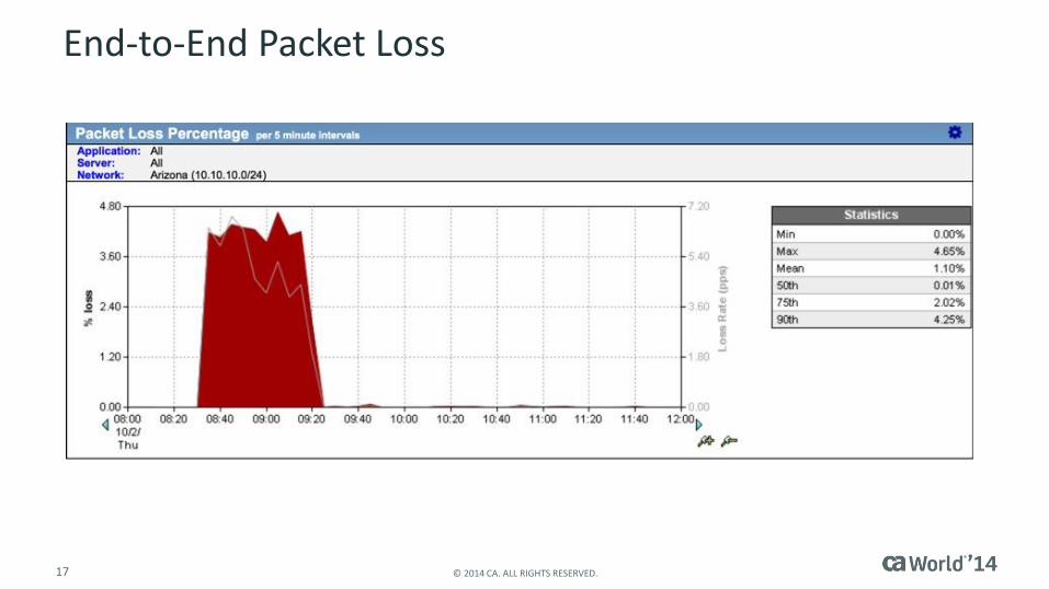
End-to-End Packet Loss
18 © 2014 CA. ALL RIGHTS RESERVED.
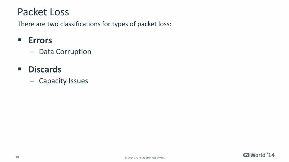
Packet Loss
Errors– Data Corruption
Discards– Capacity Issues
There are two classifications for types of packet loss:

19 © 2014 CA. ALL RIGHTS RESERVED.
Errors
Hardware– Transmitting NIC/Port
– Receiving NIC/Port
– Duplex Mismatch
Cabling– Length
– Condition Crimp
Corrosion
– Electromagnetic Interference Noise
Errors are the result of corrupted data.

20 © 2014 CA. ALL RIGHTS RESERVED.
Errors
21 © 2014 CA. ALL RIGHTS RESERVED.
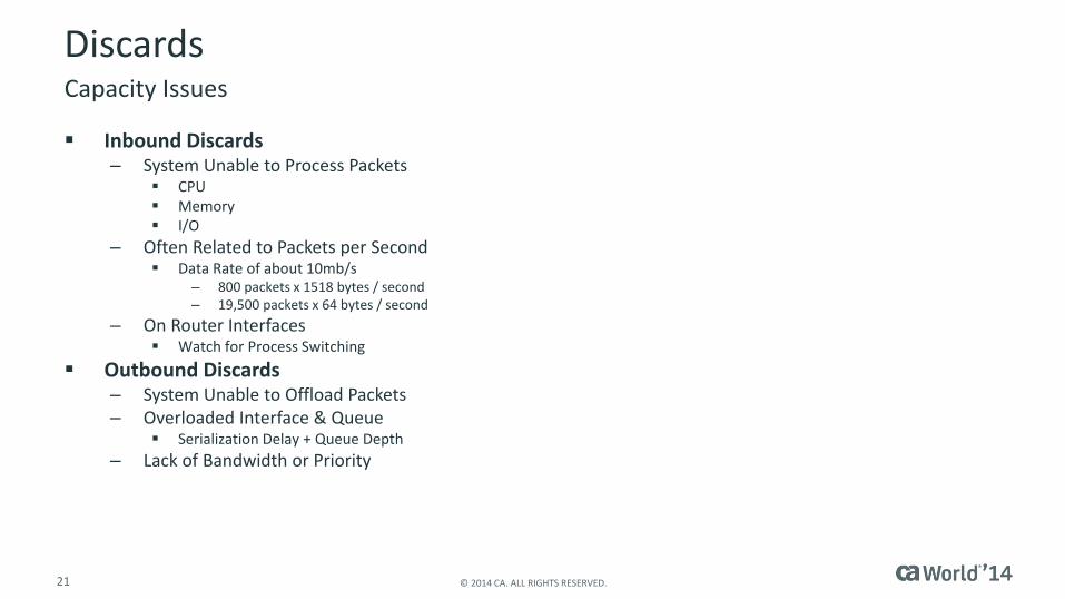
Discards
Inbound Discards– System Unable to Process Packets
CPU Memory I/O
– Often Related to Packets per Second Data Rate of about 10mb/s
– 800 packets x 1518 bytes / second– 19,500 packets x 64 bytes / second
– On Router Interfaces Watch for Process Switching
Outbound Discards– System Unable to Offload Packets– Overloaded Interface & Queue
Serialization Delay + Queue Depth
– Lack of Bandwidth or Priority
Capacity Issues

22 © 2014 CA. ALL RIGHTS RESERVED.
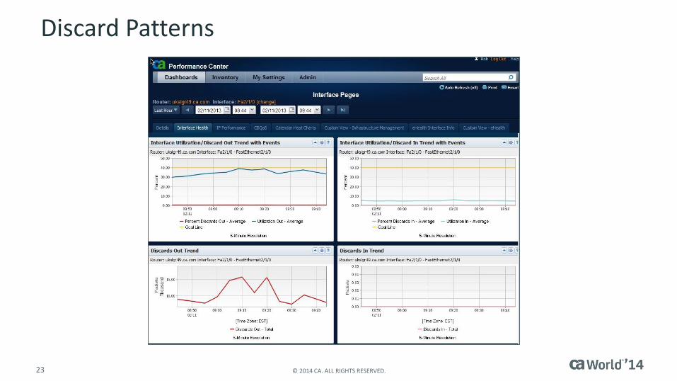
Utilization vs. Discards
23 © 2014 CA. ALL RIGHTS RESERVED.
Discard Patterns
24 © 2014 CA. ALL RIGHTS RESERVED.
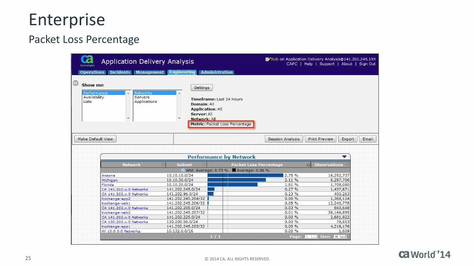
End-to-End Packet Loss
End-to-End Packet Loss– ADA provides visibility into packet loss across an enterprise or an
isolated network.
Engineering View
– Enterprise (table view)
Performance / Networks
Metric = Packet Loss Percentage
– Network (graphical view)
Components / Retransmission Delay
QoS / Packet Loss Percentage
Application Delivery Analysis (ADA)
25 © 2014 CA. ALL RIGHTS RESERVED.
EnterprisePacket Loss Percentage
26 © 2014 CA. ALL RIGHTS RESERVED.
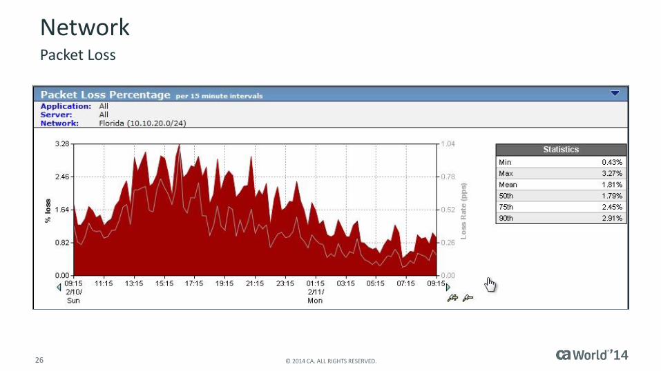
NetworkPacket Loss
27 © 2014 CA. ALL RIGHTS RESERVED.
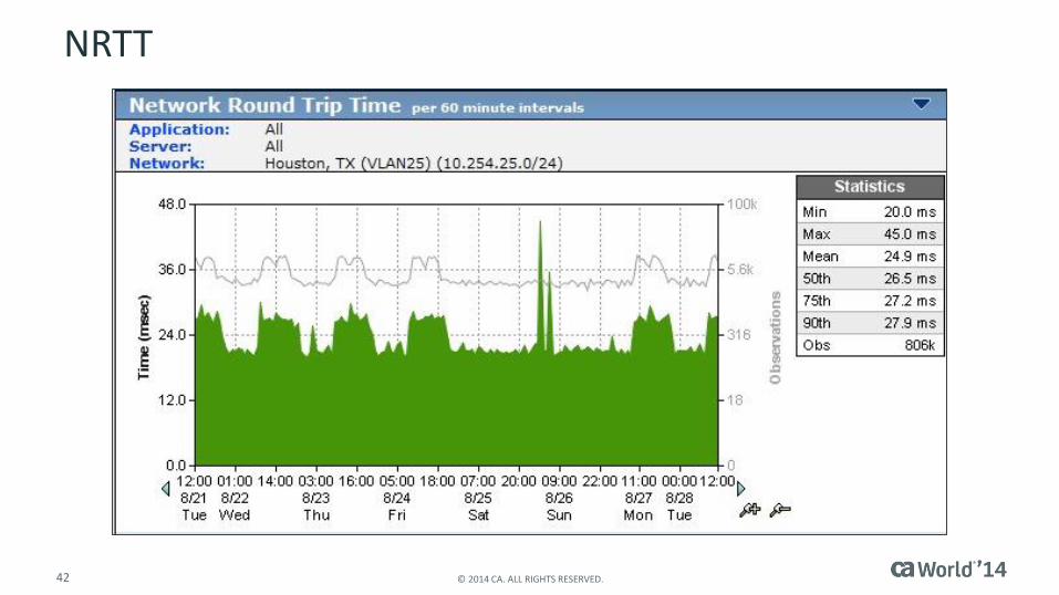
Latency
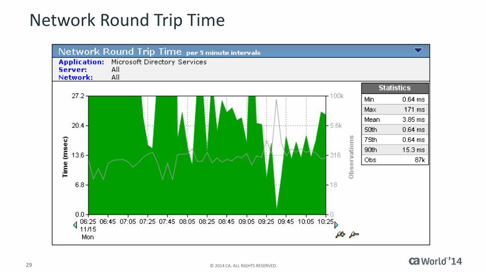
Network latency is the amount of time it takes a packet to travel from one host to another.
Network Round Trip Time is typically used to measure latency.
Network Round Trip Time (NRTT) – The amount of time for a related pair of packets to travel from point A
to point B and back
– Commonly measured using ICMP Echo Request/Reply packets
PING Utilities

28 © 2014 CA. ALL RIGHTS RESERVED.
Sources of Network Latency
Serialization Delay– Generally most significant on interface speeds below 10mbs
– Minimal delays associated with minimum packet sizes
Queuing Delay– Offers potential significant delay only when congestion exists
Distance Delay– Distances can be estimated using Internet travel map applications
Routing/Switching Delay – AKA: Forwarding Delay
Protocol Delay
There are five sources of delays associated with NRTT.
29 © 2014 CA. ALL RIGHTS RESERVED.
Network Round Trip Time
30 © 2014 CA. ALL RIGHTS RESERVED.
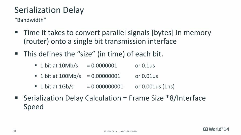
Serialization Delay
Time it takes to convert parallel signals [bytes] in memory (router) onto a single bit transmission interface
This defines the “size” (in time) of each bit.
1 bit at 10Mb/s = 0.0000001 or 0.1us
1 bit at 100Mb/s = 0.00000001 or 0.01us
1 bit at 1Gb/s = 0.000000001 or 0.001us (1ns)
Serialization Delay Calculation = Frame Size *8/Interface Speed
“Bandwidth”
31 © 2014 CA. ALL RIGHTS RESERVED.
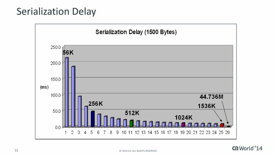
Serialization Delay
32 © 2014 CA. ALL RIGHTS RESERVED.
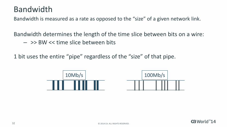
Bandwidth
Bandwidth determines the length of the time slice between bits on a wire:
– >> BW << time slice between bits
1 bit uses the entire “pipe” regardless of the “size” of that pipe.
Bandwidth is measured as a rate as opposed to the “size” of a given network link.
10Mb/s 100Mb/s
33 © 2014 CA. ALL RIGHTS RESERVED.
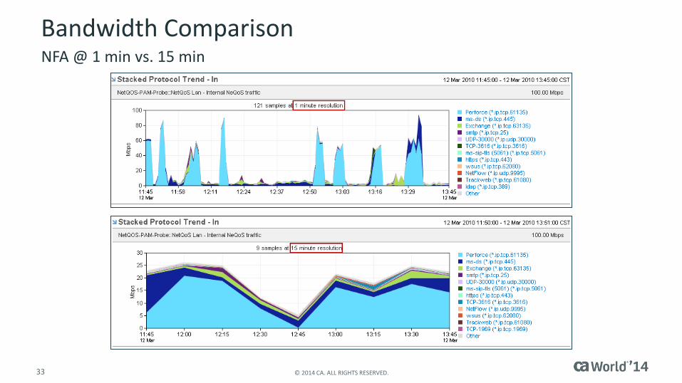
Bandwidth ComparisonNFA @ 1 min vs. 15 min
34 © 2014 CA. ALL RIGHTS RESERVED.
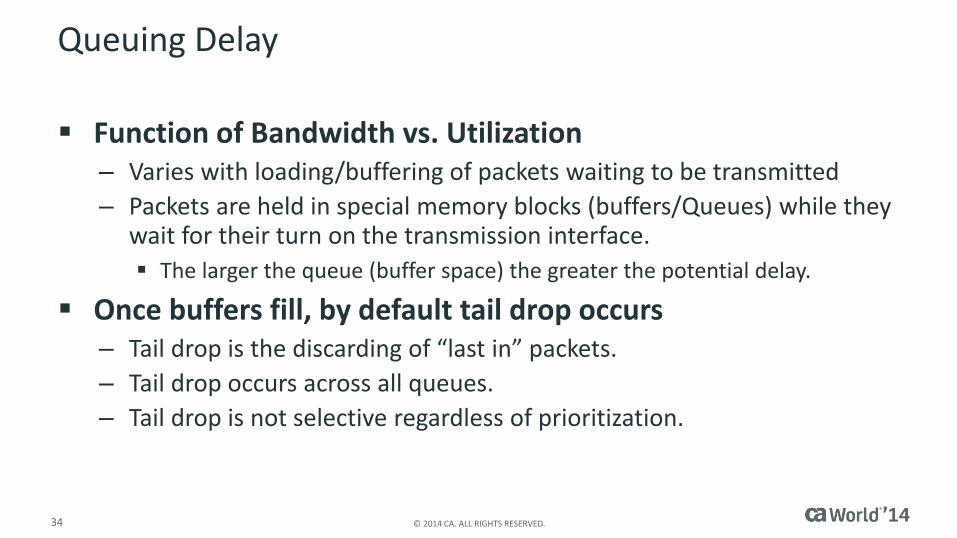
Queuing Delay
Function of Bandwidth vs. Utilization– Varies with loading/buffering of packets waiting to be transmitted
– Packets are held in special memory blocks (buffers/Queues) while they wait for their turn on the transmission interface.
The larger the queue (buffer space) the greater the potential delay.
Once buffers fill, by default tail drop occurs– Tail drop is the discarding of “last in” packets.
– Tail drop occurs across all queues.
– Tail drop is not selective regardless of prioritization.
35 © 2014 CA. ALL RIGHTS RESERVED.
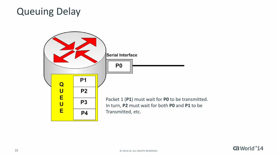
Queuing Delay
Packet 1 (P1) must wait for P0 to be transmitted.In turn, P2 must wait for both P0 and P1 to be Transmitted, etc.

36 © 2014 CA. ALL RIGHTS RESERVED.
Distance Delay
Bits travel about 50-70 percent the speed of light. – Depending upon the transmission media
The speed of light traveling on fiber is about 5.50us (microseconds) per Kilometer.
The speed of electricity traveling on copper is about 5.56us (microseconds) per Kilometer.
The speed of microwave communication is about 3.30us (microseconds) per Kilometer.
Distance Delay is constant on a given path in a network.

37 © 2014 CA. ALL RIGHTS RESERVED.
Routing/Switching Delay
The amount of time it takes for a router or switch to internally process a packet in terms of
forwarding decision:
– Destination lookup in Forwarding Information Base (FIB)
IP Route Table
Ethernet MAC/CAM (Media Access Control/Contents Addressable Memory) Table
MPLS Label Information Base (LIB)
– The amount of time to apply any administrative policy
Network Access Control Lists (ACLs)
Policy Based Routing (PBR)
Some administrative policies can cause a router to begin process switching every packet
– Often result in Inbound Discards
– Will increase latency
– Hardware/Software errors may introduce delay
Relatively Fixed and Known
Should not change [along a given path] in a stable environment
AKA: Forwarding Delay
38 © 2014 CA. ALL RIGHTS RESERVED.
Protocol Delay
The amount of time communication Protocols may induce into a packet request/response pair– CSMA/CD (Carrier-Sense Multiple Access/Collision Detection)
– CSMA/CA (Carrier-Sense Multiple Access/Collision Avoidance)
– CTS/RTS (Clear-To-Send/Request-To-Send)
– Delayed TCP Acknowledgement (ACK) Timers in TCP applications
39 © 2014 CA. ALL RIGHTS RESERVED.
TCP Delay ACK
Delayed Acknowledgement– Let’s not acknowledge every received TCP Segment.
– Instead, let’s only acknowledge every other one (most common).
What if all payload can fit within a single segment?– When first packet is received, receiver starts Delay ACK timer.
– If a second segment arrives prior to timer expiring, one ACK is sent to acknowledge both segments.
– If, prior to the timer expiring, the receiver has a response (i.e. payload) to deliver to that TCP Session, the ACK will be included with the new payload (piggyback ACK).
– If the second segment has not arrived, and no response is available to transmit.
TCP will ACK receipt of the single segment once timer has expired
Typical TCP Delay ACK timer ~200
40 © 2014 CA. ALL RIGHTS RESERVED.
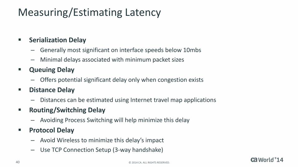
Measuring/Estimating Latency
Serialization Delay
– Generally most significant on interface speeds below 10mbs
– Minimal delays associated with minimum packet sizes
Queuing Delay
– Offers potential significant delay only when congestion exists
Distance Delay
– Distances can be estimated using Internet travel map applications
Routing/Switching Delay
– Avoiding Process Switching will help minimize this delay
Protocol Delay
– Avoid Wireless to minimize this delay’s impact
– Use TCP Connection Setup (3-way handshake)

41 © 2014 CA. ALL RIGHTS RESERVED.
Measuring Latency
Network Round Trip Time (NRTT)– Serialization + Queuing + Distance + Forwarding + Protocol
Network Connection Time (NCT)– Queuing + Distance
Forwarding < 3ms round trip
Minimal Serialization (0.3ms per T-1 hop)
No Protocol Delay/TCP Delay ACK
– This assumes elimination of wireless protocols by measuring LAN segments only
42 © 2014 CA. ALL RIGHTS RESERVED.
NRTT
43 © 2014 CA. ALL RIGHTS RESERVED.
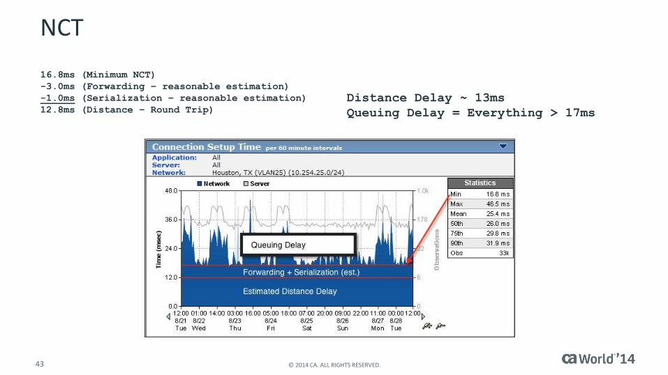
NCT
16.8ms (Minimum NCT)
-3.0ms (Forwarding – reasonable estimation)
-1.0ms (Serialization – reasonable estimation)
12.8ms (Distance – Round Trip)
Distance Delay ~ 13ms
Queuing Delay = Everything > 17ms

44 © 2014 CA. ALL RIGHTS RESERVED.
What Happened Here?

Reference ModelsKPIs–User Impact
46 © 2014 CA. ALL RIGHTS RESERVED.
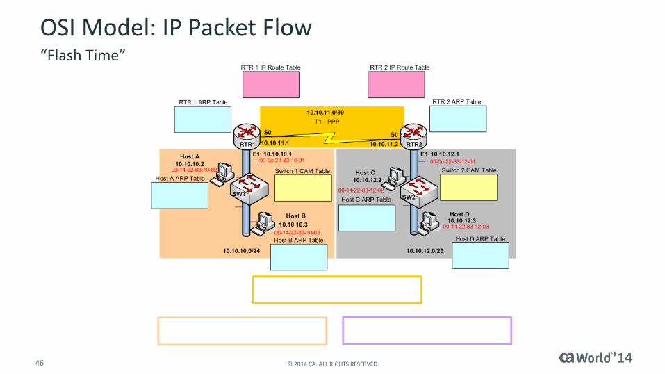
OSI Model: IP Packet Flow“Flash Time”

47 © 2014 CA. ALL RIGHTS RESERVED.
Physical
Reference Models Side-by-Side
Data Link
Network
Transport
Session
Presentation
Application
NetworkAccess
Internet
Host-to-Host
Process or
Application
OSIInternet or
TCP
(Local)
(Remote)

48 © 2014 CA. ALL RIGHTS RESERVED.
Data Encapsulation
Data
Data
Data
T
N
D CRC
1111 01111 01111 01111 01111 011110
ULP Data
Data
Data
Data
T
N
D CRC
ULP Data
Client Server
49 © 2014 CA. ALL RIGHTS RESERVED.
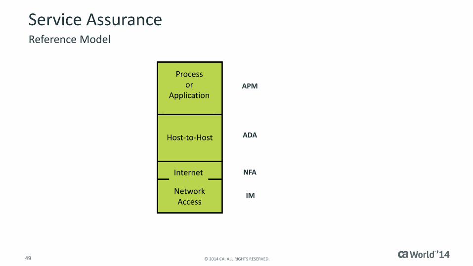
Service AssuranceReference Model
NetworkAccess
Internet
Host-to-Host
Process or
ApplicationAPM
ADA
NFA
IM
50 © 2014 CA. ALL RIGHTS RESERVED.
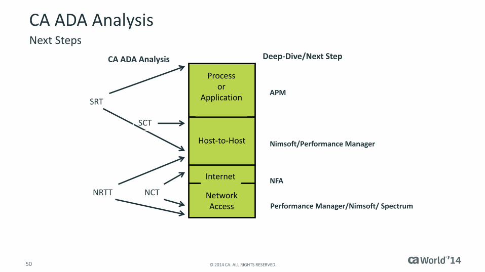
CA ADA AnalysisNext Steps
NetworkAccess
Internet
Host-to-Host
Process or
ApplicationSRT
NRTT NCT
CA ADA Analysis Deep-Dive/Next Step
SCT
APM
Nimsoft/Performance Manager
NFA
Performance Manager/Nimsoft/ Spectrum
IP Packet FragmentationIPV4 Fragmented Performance

52 © 2014 CA. ALL RIGHTS RESERVED.
Objective
Provide an operational understanding into the causes of packet fragmentation.
Explore the consequences of allowing fragmentation. – Performance Risk
– Security Risk
Discuss steps that can be taken to minimize the risks associated with fragmentation.
An In-Depth Look Into the Effects Packet Fragmentation Has on Performance

53 © 2014 CA. ALL RIGHTS RESERVED.
Size Is Relative
Frame Size (layer-2)– Ethernet Maximum Frame Size = 1518 bytes– Includes 4-Byte CRC at the end of the frame– Does not include frame extensions
VLAN Tags Jumbo Frames
Packet Size (layer-3)– Layer-2 Header (+ CRC) = 18 bytes– Maximum Packet Size = 1500 bytes
Segment Size (layer-4)– Maximum Segment Size (MSS) = 1460
IP Header = 20 bytes TCP Header = 20 bytes (typically) TCP Payload = 1460 bytes
54 © 2014 CA. ALL RIGHTS RESERVED.
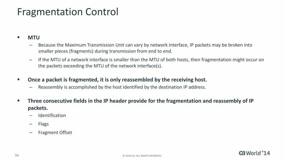
Fragmentation Control
MTU– Because the Maximum Transmission Unit can vary by network interface, IP packets may be broken into
smaller pieces (fragments) during transmission from end to end.
– If the MTU of a network interface is smaller than the MTU of both hosts, then fragmentation might occur on the packets exceeding the MTU of the network interface(s).
Once a packet is fragmented, it is only reassembled by the receiving host.– Reassembly is accomplished by the host identified by the destination IP address.
Three consecutive fields in the IP header provide for the fragmentation and reassembly of IP packets.– Identification
– Flags
– Fragment Offset
55 © 2014 CA. ALL RIGHTS RESERVED.
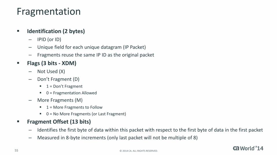
Fragmentation
Identification (2 bytes)
– IPID (or ID)
– Unique field for each unique datagram (IP Packet)
– Fragments reuse the same IP ID as the original packet
Flags (3 bits - XDM)
– Not Used (X)
– Don’t Fragment (D)
1 = Don’t Fragment
0 = Fragmentation Allowed
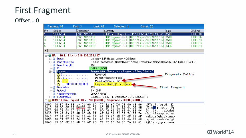
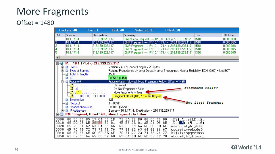
– More Fragments (M)
1 = More Fragments to Follow
0 = No More Fragments (or Last Fragment)
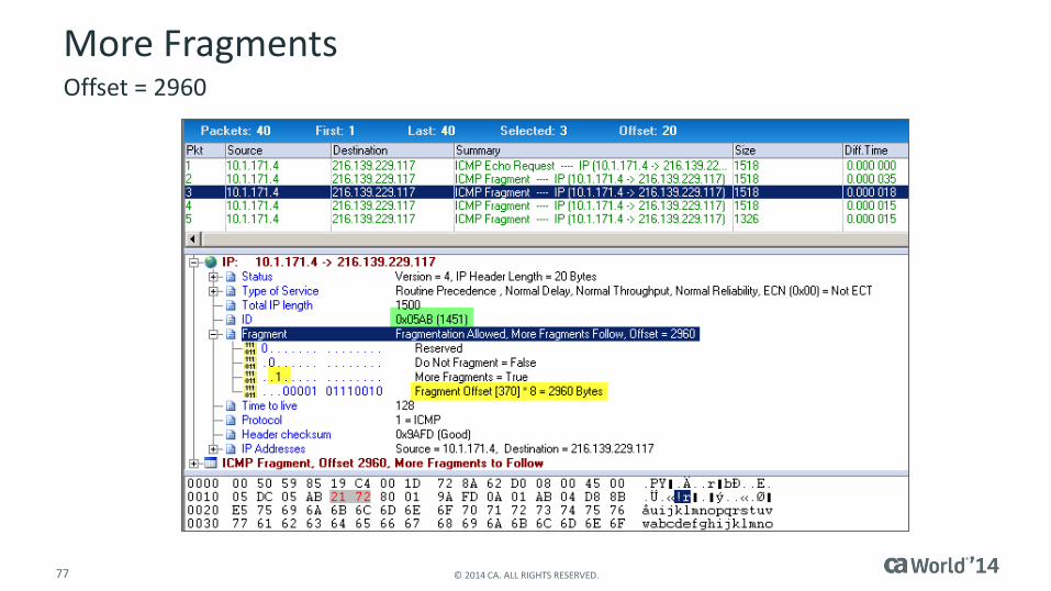
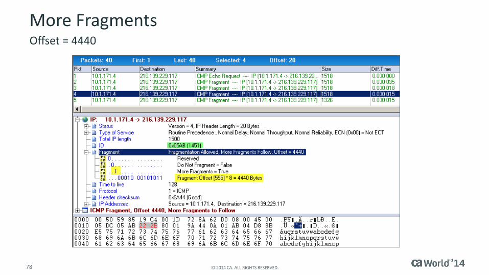
Fragment Offset (13 bits)
– Identifies the first byte of data within this packet with respect to the first byte of data in the first packet
– Measured in 8-byte increments (only last packet will not be multiple of 8)
56 © 2014 CA. ALL RIGHTS RESERVED.
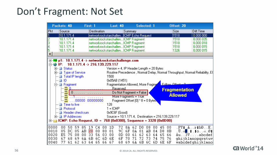
Don’t Fragment: Not Set

Path MTU DiscoveryFragmented Performance
58 © 2014 CA. ALL RIGHTS RESERVED.
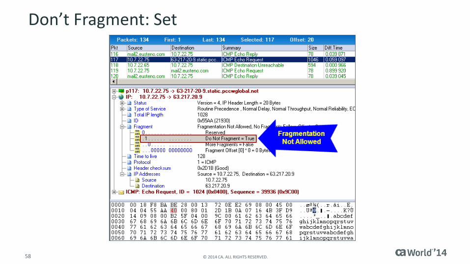
Don’t Fragment: Set
59 © 2014 CA. ALL RIGHTS RESERVED.
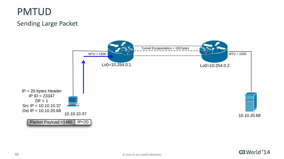
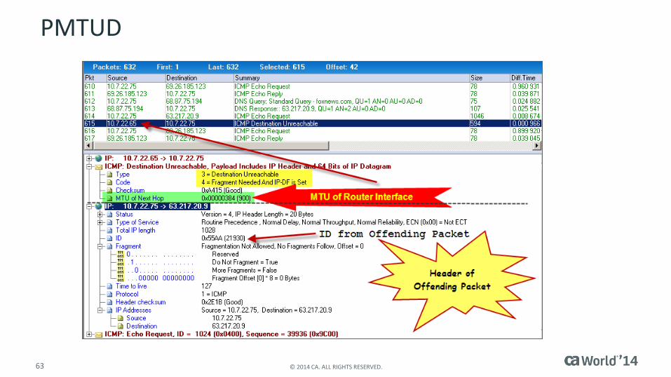
PMTUD
Path MTU Discovery– PMTUD
Don’t Fragment Bit = 1– Routers not allowed to fragment the packet
ICMP is used to notify sender that – A packet was dropped
Including an indication of which packet Returns “offending” packet header
– IP Address of the router dropping the packet This is the source IP sending the ICMP message
– MTU limitation encountered Allows sending host to resend using smaller packets
Path Maximum Transmission Unit Discovery
60 © 2014 CA. ALL RIGHTS RESERVED.
PMTUD
V V
IP=20Packet Payload =1480
Lo0=10.254.0.1
10.10.20.68
MTU = 1500 MTU = 1500
Tunnel Encapsulation = 100 bytes
10.10.10.37
Lo0=10.254.0.2
IP = 20 bytes HeaderIP ID = 23347
DF = 1Src IP = 10.10.10.37Dst IP = 10.10.20.68
Sending Large Packet

61 © 2014 CA. ALL RIGHTS RESERVED.
PMTUD Bit Bucket
V V
IP=20Packet Payload =1480
Lo0=10.254.0.1
10.10.20.68
MTU = 1500 MTU = 1500
Tunnel Encapsulation = 100 bytes
10.10.10.37
Lo0=10.254.0.2
IP = 20 bytes HeaderIP ID = 23347
DF = 1Src IP = 10.10.10.37Dst IP = 10.10.20.68
62 © 2014 CA. ALL RIGHTS RESERVED.
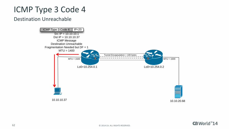
V V
Lo0=10.254.0.1
10.10.20.68
MTU = 1500 MTU = 1500
Tunnel Encapsulation = 100 bytes
10.10.10.37
Lo0=10.254.0.2
IP=20ICMP Type 3 Code 4
Src IP = 10.10.10.1Dst IP = 10.10.10.37
ICMP MessageDestination Unreachable
Fragmentation Needed but DF = 1MTU = 1400
ICMP Type 3 Code 4Destination Unreachable
63 © 2014 CA. ALL RIGHTS RESERVED.
PMTUD

64 © 2014 CA. ALL RIGHTS RESERVED.
PMTUD Success
V V
Lo0=10.254.0.1
10.10.20.68
MTU = 1500 MTU = 1500
Tunnel Encapsulation = 100 bytes
10.10.10.37
Lo0=10.254.0.2
IP = 20 bytes HeaderIP ID = 23348
DF = 1Src IP = 10.10.10.37Dst IP = 10.10.20.68
IP=20Packet Payload =1380
IP=20Payload =100
IP = 20 bytes HeaderIP ID = 23349
DF = 1Src IP = 10.10.10.37Dst IP = 10.10.20.68
No Fragmentation
65 © 2014 CA. ALL RIGHTS RESERVED.
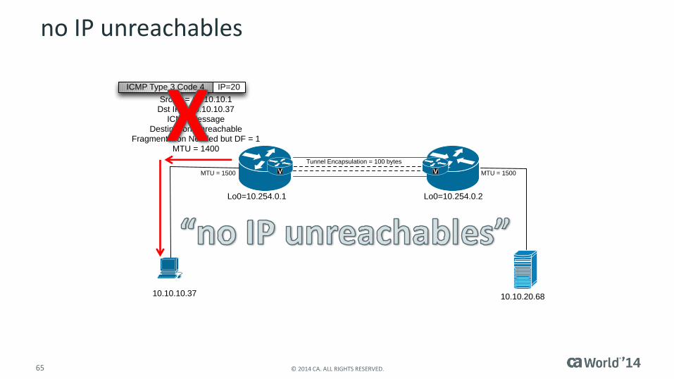
V V
Lo0=10.254.0.1
10.10.20.68
MTU = 1500 MTU = 1500
Tunnel Encapsulation = 100 bytes
10.10.10.37
Lo0=10.254.0.2
IP=20ICMP Type 3 Code 4
Src IP = 10.10.10.1Dst IP = 10.10.10.37
ICMP MessageDestination Unreachable
Fragmentation Needed but DF = 1MTU = 1400
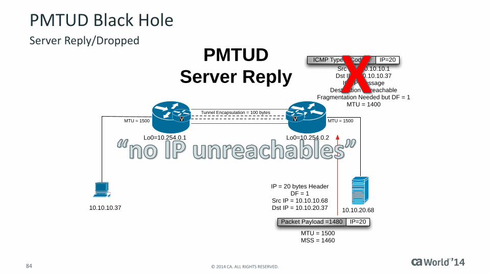
no IP unreachables
FragmentationFragmented Performance

67 © 2014 CA. ALL RIGHTS RESERVED.
Fragmentation
V V
IP=20Packet Payload =1480
Lo0=10.254.0.1
10.10.20.68
MTU = 1500 MTU = 1500
Tunnel Encapsulation = 100 bytes
10.10.10.37
Lo0=10.254.0.2
IP = 20 bytes HeaderIP ID = 23347
DF = 1Src IP = 10.10.10.37Dst IP = 10.10.20.68
IP = 20 bytes HeaderIP ID = 13007
DF = 0Src IP = 10.254.0.1Dst IP = 10.254.0.2
Packet Payload = 1400
Payload =180
IP = 20 bytes HeaderIP ID = 13007
DF = 0Src IP = 10.254.0.1Dst IP = 10.254.0.2
IP=20
IP=20GRE=80
GRE=80
Packet Payload =1500
New IP = 20 bytes HeaderIP ID = 13007
DF = 0Src IP = 10.254.0.1Dst IP = 10.254.0.2
IP=20GRE=80 1600 Bytes

The Cost of FragmentationFragmented Performance

69 © 2014 CA. ALL RIGHTS RESERVED.
Cost of Fragmentation
On receiving a fragment (not necessarily the first fragment in the original datagram), the receiving IP stack will allocate several reassembly resources:– A 64KB data buffer for the IP payload
– A 60-byte header buffer for the IP header (allows for IP options)
– A fragment block bit table (1024 or 8192 bits) used to track reception of datagram fragments
– A total length data variable
– A reassembly timer. RFC 791 suggests a default timer of no less than 15 seconds
– As fragments are received, the timer is set to the greater of the current timer or the value of the fragment’s TTL field
IP Fragment Reception
70 © 2014 CA. ALL RIGHTS RESERVED.
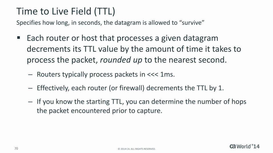
Time to Live Field (TTL)
Each router or host that processes a given datagram decrements its TTL value by the amount of time it takes to process the packet, rounded up to the nearest second.
– Routers typically process packets in <<< 1ms.
– Effectively, each router (or firewall) decrements the TTL by 1.
– If you know the starting TTL, you can determine the number of hops the packet encountered prior to capture.
Specifies how long, in seconds, the datagram is allowed to “survive”

71 © 2014 CA. ALL RIGHTS RESERVED.
How Long Do I Have?
72 © 2014 CA. ALL RIGHTS RESERVED.
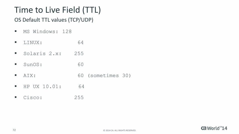
Time to Live Field (TTL)
MS Windows: 128
LINUX: 64
Solaris 2.x: 255
SunOS: 60
AIX: 60 (sometimes 30)
HP UX 10.01: 64
Cisco: 255
OS Default TTL values (TCP/UDP)
Observing FragmentationFragmented Performance

74 © 2014 CA. ALL RIGHTS RESERVED.
Observer Custom Summary
75 © 2014 CA. ALL RIGHTS RESERVED.
First FragmentOffset = 0
76 © 2014 CA. ALL RIGHTS RESERVED.
More FragmentsOffset = 1480
77 © 2014 CA. ALL RIGHTS RESERVED.
More FragmentsOffset = 2960
78 © 2014 CA. ALL RIGHTS RESERVED.
More FragmentsOffset = 4440
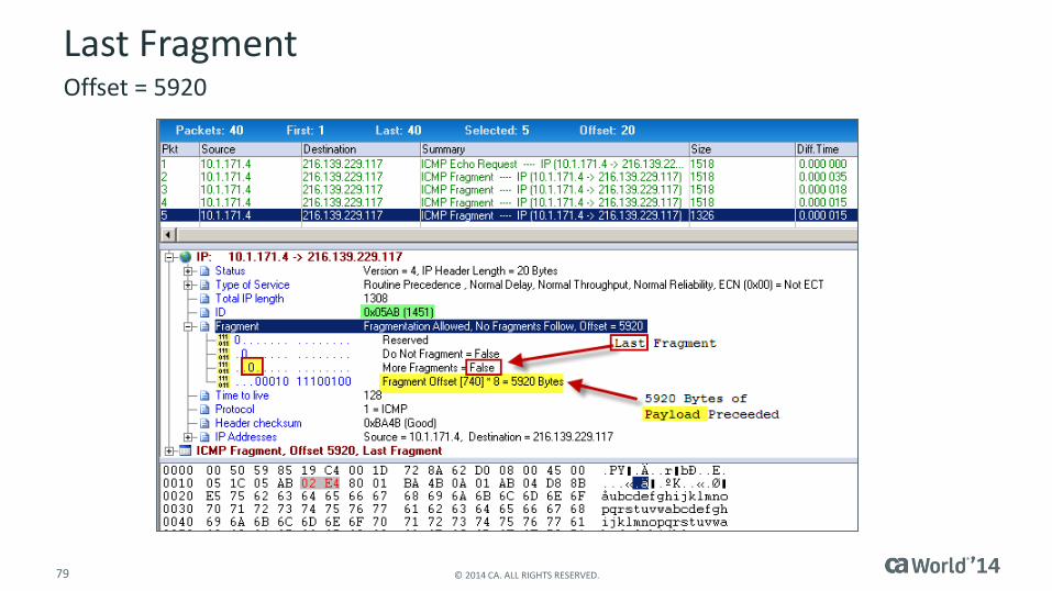
79 © 2014 CA. ALL RIGHTS RESERVED.
Last FragmentOffset = 5920

TCP Fragmentation AvoidanceFragmented Performance

PMTUD Black HoleFragmented Performance
82 © 2014 CA. ALL RIGHTS RESERVED.
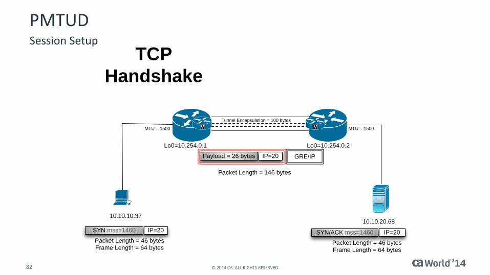
V V
IP=20SYN mss=1460
Lo0=10.254.0.1
10.10.20.68
MTU = 1500 MTU = 1500
Tunnel Encapsulation = 100 bytes
10.10.10.37
Lo0=10.254.0.2
TCP
Handshake
Packet Length = 46 bytesFrame Length = 64 bytes
IP=20SYN/ACK mss=1460
Packet Length = 46 bytesFrame Length = 64 bytes
IP=20Payload = 26 bytes GRE/IP
Packet Length = 146 bytes
PMTUDSession Setup

83 © 2014 CA. ALL RIGHTS RESERVED.
V V
IP=20TCP Payload= 300 Bytes
Lo0=10.254.0.1
10.10.20.68
MTU = 1500 MTU = 1500
Tunnel Encapsulation = 100 bytes
10.10.10.37
Lo0=10.254.0.2
TCP
Command
Packet Length = 440 bytes
IP=20TCP Payload= 300 Bytes GRE/IP
Packet Length = 340 bytesFrame Length = 358 bytes
IP=20TCP Payload= 300 Bytes
Packet Length = 340 bytesFrame Length = 358 bytes
PMTUDCommand
84 © 2014 CA. ALL RIGHTS RESERVED.
V V
IP=20Packet Payload =1480
Lo0=10.254.0.1
10.10.20.68
MTU = 1500 MTU = 1500
Tunnel Encapsulation = 100 bytes
10.10.10.37
Lo0=10.254.0.2
IP = 20 bytes HeaderDF = 1
Src IP = 10.10.10.68Dst IP = 10.10.20.37
PMTUD
Server Reply
MTU = 1500MSS = 1460
IP=20ICMP Type 3 Code 4
Src IP = 10.10.10.1Dst IP = 10.10.10.37
ICMP MessageDestination Unreachable
Fragmentation Needed but DF = 1MTU = 1400
PMTUD Black HoleServer Reply/Dropped

85 © 2014 CA. ALL RIGHTS RESERVED.
V V
IP=20Packet Payload = 556
Lo0=10.254.0.1
10.10.20.68
MTU = 1500 MTU = 1500
Tunnel Encapsulation = 100 bytes
10.10.10.37
Lo0=10.254.0.2
IP = 20 bytes HeaderDF = 1
Src IP = 10.10.10.68Dst IP = 10.10.20.37
PMTUD Black Hole
Server Reply
MTU = 576MSS = 536 IP=20Packet Payload = 556
IP=20Packet Payload = 556
IP=20Packet Payload = 556
PMTUD Black Hole“Host Workaround”
“

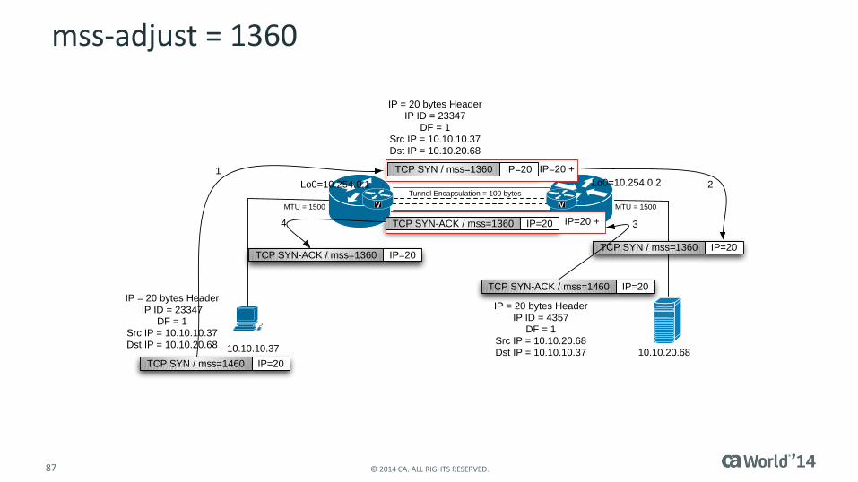
MSS AdjustFragmented Performance
87 © 2014 CA. ALL RIGHTS RESERVED.
IP=20 +
IP=20 +
V V
IP=20TCP SYN / mss=1460
Lo0=10.254.0.1
10.10.20.68
MTU = 1500 MTU = 1500
Tunnel Encapsulation = 100 bytes
10.10.10.37
Lo0=10.254.0.2
IP = 20 bytes HeaderIP ID = 23347
DF = 1Src IP = 10.10.10.37Dst IP = 10.10.20.68
IP=20TCP SYN / mss=1360
IP = 20 bytes HeaderIP ID = 23347
DF = 1Src IP = 10.10.10.37Dst IP = 10.10.20.68
IP=20TCP SYN-ACK / mss=1460
IP = 20 bytes HeaderIP ID = 4357
DF = 1Src IP = 10.10.20.68Dst IP = 10.10.10.37
IP=20TCP SYN-ACK / mss=1360
IP=20TCP SYN-ACK / mss=1360IP=20TCP SYN / mss=1360
1
2
34
mss-adjust = 1360
Issues With FragmentationFragmented Performance
89 © 2014 CA. ALL RIGHTS RESERVED.
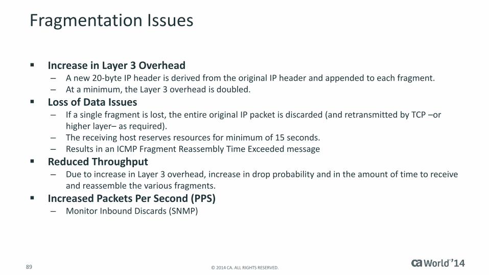
Fragmentation Issues
Increase in Layer 3 Overhead – A new 20-byte IP header is derived from the original IP header and appended to each fragment.– At a minimum, the Layer 3 overhead is doubled.
Loss of Data Issues– If a single fragment is lost, the entire original IP packet is discarded (and retransmitted by TCP –or
higher layer– as required).– The receiving host reserves resources for minimum of 15 seconds.– Results in an ICMP Fragment Reassembly Time Exceeded message
Reduced Throughput – Due to increase in Layer 3 overhead, increase in drop probability and in the amount of time to receive
and reassemble the various fragments.
Increased Packets Per Second (PPS)– Monitor Inbound Discards (SNMP)
90 © 2014 CA. ALL RIGHTS RESERVED.
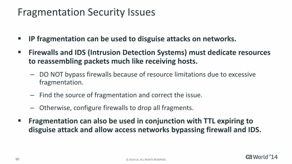
Fragmentation Security Issues
IP fragmentation can be used to disguise attacks on networks.
Firewalls and IDS (Intrusion Detection Systems) must dedicate resources to reassembling packets much like receiving hosts.
– DO NOT bypass firewalls because of resource limitations due to excessive fragmentation.
– Find the source of fragmentation and correct the issue.
– Otherwise, configure firewalls to drop all fragments.
Fragmentation can also be used in conjunction with TTL expiring to disguise attack and allow access networks bypassing firewall and IDS.
91 © 2014 CA. ALL RIGHTS RESERVED.
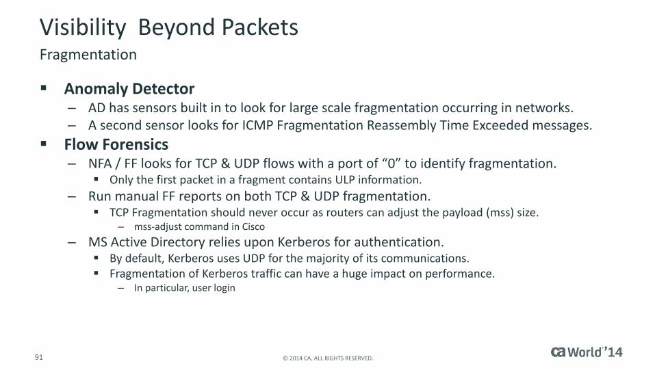
Visibility Beyond Packets
Anomaly Detector– AD has sensors built in to look for large scale fragmentation occurring in networks.– A second sensor looks for ICMP Fragmentation Reassembly Time Exceeded messages.
Flow Forensics– NFA / FF looks for TCP & UDP flows with a port of “0” to identify fragmentation.
Only the first packet in a fragment contains ULP information.
– Run manual FF reports on both TCP & UDP fragmentation. TCP Fragmentation should never occur as routers can adjust the payload (mss) size.
– mss-adjust command in Cisco
– MS Active Directory relies upon Kerberos for authentication. By default, Kerberos uses UDP for the majority of its communications. Fragmentation of Kerberos traffic can have a huge impact on performance.
– In particular, user login
Fragmentation
TCP/IP Throughput LimitationsKPIs–User Impact

93 © 2014 CA. ALL RIGHTS RESERVED.
Throughput Limitations
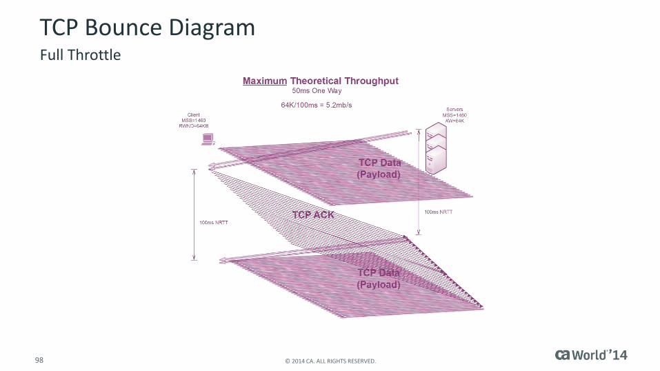
Maximum Theoretical Throughput– The Calculated Potential of a Given Network/Application
Based on TCP Payload
– The best delivery possible if all other conditions are perfect Zero Packet Loss Unlimited Bandwidth
Factors limiting the rate of data transferred across a network (per TCP Session)– The Network
Packet Loss Latency
– TCP Congestion Window Active Window Smaller of Receive Window and Sender’s Active Window Discussed in detail during “The True Cost of Packet Loss”
– Application Response Size
94 © 2014 CA. ALL RIGHTS RESERVED.
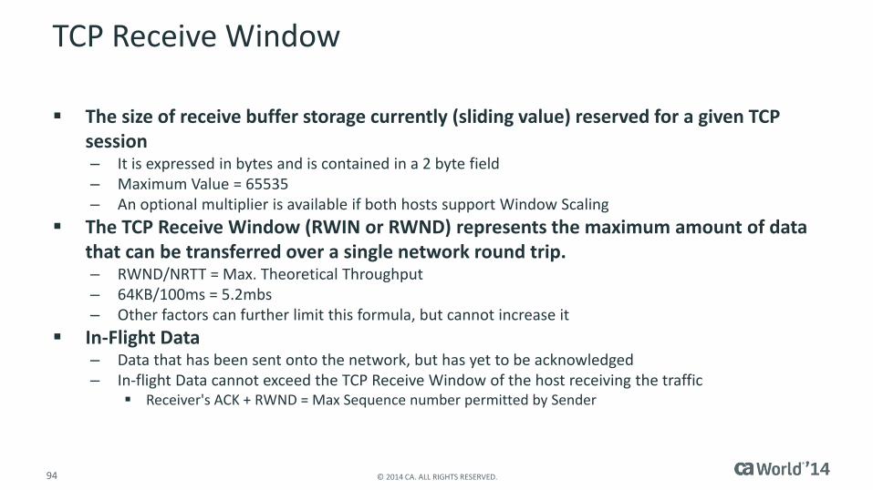
TCP Receive Window
The size of receive buffer storage currently (sliding value) reserved for a given TCP session– It is expressed in bytes and is contained in a 2 byte field– Maximum Value = 65535 – An optional multiplier is available if both hosts support Window Scaling
The TCP Receive Window (RWIN or RWND) represents the maximum amount of data that can be transferred over a single network round trip.– RWND/NRTT = Max. Theoretical Throughput – 64KB/100ms = 5.2mbs – Other factors can further limit this formula, but cannot increase it
In-Flight Data– Data that has been sent onto the network, but has yet to be acknowledged– In-flight Data cannot exceed the TCP Receive Window of the host receiving the traffic
Receiver's ACK + RWND = Max Sequence number permitted by Sender

95 © 2014 CA. ALL RIGHTS RESERVED.
Receive Window
96 © 2014 CA. ALL RIGHTS RESERVED.
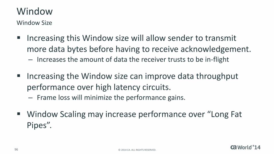
Window
Increasing this Window size will allow sender to transmit more data bytes before having to receive acknowledgement.– Increases the amount of data the receiver trusts to be in-flight
Increasing the Window size can improve data throughput performance over high latency circuits.– Frame loss will minimize the performance gains.
Window Scaling may increase performance over “Long Fat Pipes”.
Window Size

TCP/IP Throughput CalculationsKPIs–User Impact
98 © 2014 CA. ALL RIGHTS RESERVED.
TCP Bounce DiagramFull Throttle

99 © 2014 CA. ALL RIGHTS RESERVED.
Application Data Block Size
Applications may implement a read/write size smaller than the TCP Receive Window.– RWND = 64K (65535)
– NRTT = 100ms
– But, the application can only read 12KB at a time
12KB/100ms = 983kbs
Regardless of TCP Receive Window (provided it is at least 12KB)

100 © 2014 CA. ALL RIGHTS RESERVED.
Max Theoretical ThroughputApplication Limiting vs. TCP Window Limiting
12KB/40ms = 2.4mbs 12KB/370ms = 265kbs
Data Block Size (DBS) Network Delay (NRTT)
DBS/NRTT = Max. Possible Throughput

Congestion ControlsKPIs–User Impact
102 © 2014 CA. ALL RIGHTS RESERVED.
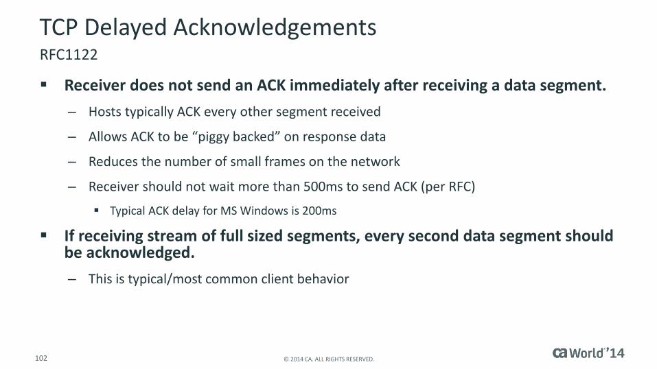
TCP Delayed Acknowledgements
Receiver does not send an ACK immediately after receiving a data segment.
– Hosts typically ACK every other segment received
– Allows ACK to be “piggy backed” on response data
– Reduces the number of small frames on the network
– Receiver should not wait more than 500ms to send ACK (per RFC)
Typical ACK delay for MS Windows is 200ms
If receiving stream of full sized segments, every second data segment should be acknowledged.
– This is typical/most common client behavior
RFC1122

103 © 2014 CA. ALL RIGHTS RESERVED.
TCP Slow Start
Prevents sender from overloading internetworking devices with Frames at the beginning of the TCP conversation
The congestion window is set to the Initial Window at the beginning of a TCP Session.
– Initial Window (IW) = 2 segments (most common default)
Additional windows regarding throughput affecting the sending device’s TCP
– Congestion Window (CWND)
– Active Window (AW)
AW will be the smaller of the Receiver's RWND and the Sender’s CWND
Sender will never have more than AW In-Flight
– In-Flight = segments sent onto network but yet to be acknowledged
RFC2001

104 © 2014 CA. ALL RIGHTS RESERVED.
TCP Slow Start + Ack Delay

105 © 2014 CA. ALL RIGHTS RESERVED.
TCP Slow Start
Microsoft sets the initial congestion window to two segments.
Each time an Acknowledgement is received, the congestion window is increased by one segment size.
– Regardless of the number of segments the ACK represents
The sender can transmit unacknowledged data up to the smaller of either the congestion windows or the receiver’s advertised windows.
When Does Slow Start Run?
– At the beginning of every TCP Session
– Whenever a Sender’s Retransmit Timer Expires and a Packet is Resent

106 © 2014 CA. ALL RIGHTS RESERVED.
TCP Slow Start + ACK DelayFailed PMTUD
107 © 2014 CA. ALL RIGHTS RESERVED.
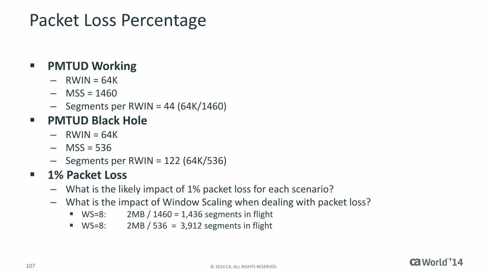
Packet Loss Percentage
PMTUD Working– RWIN = 64K – MSS = 1460– Segments per RWIN = 44 (64K/1460)
PMTUD Black Hole– RWIN = 64K– MSS = 536– Segments per RWIN = 122 (64K/536)
1% Packet Loss– What is the likely impact of 1% packet loss for each scenario?– What is the impact of Window Scaling when dealing with packet loss?
WS=8: 2MB / 1460 = 1,436 segments in flight WS=8: 2MB / 536 = 3,912 segments in flight
108 © 2014 CA. ALL RIGHTS RESERVED.
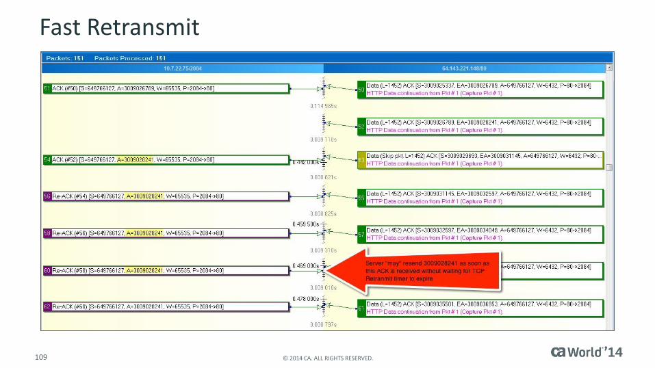
TCP Fast Retransmit
If TCP Frames are received out of order, the receiver will send duplicate
ACKs for a segment.
– As subsequent segments are received, the receiver repeats ACK for the outstanding
segment once every time a subsequent segment is received.
When the sender receives the multiple ACKs, it will retransmit the missing
segment, without waiting for the retransmit timer to expire.
– Four ACKs for same outstanding segment
– Results in transmitting station entering Congestion Avoidance
– Process is identical whether or not SACK is active
109 © 2014 CA. ALL RIGHTS RESERVED.
Fast Retransmit

110 © 2014 CA. ALL RIGHTS RESERVED.
Congestion Avoidance
The Congestion Avoidance Algorithm is used when the sender retransmit under Fast Retransmit conditions as opposed to its TCP Retransmit Timer expiring.– Active Window = ½ CWND
– AW increments by 1 segment each time the entire outstanding AW is ACK’d
Basically, AW = AW+1 per NRTT
– Reduces current throughput by 50% and slowly increase from there
– Example
CWND = 44 segments (~64KB)
Fast Retransmit Detected / Segment Retransmitted
AW = 22 segments
Once all 22 segments are ACK’d, AW = 23 segments
Take AwayIntroduction to Performance Management
112 © 2014 CA. ALL RIGHTS RESERVED.
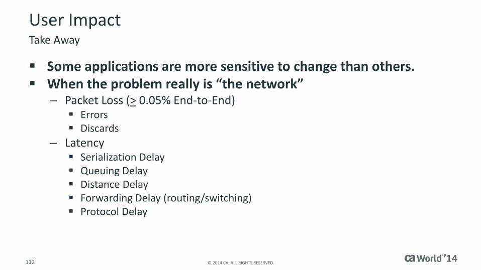
User Impact
Some applications are more sensitive to change than others. When the problem really is “the network”
– Packet Loss (> 0.05% End-to-End) Errors Discards
– Latency Serialization Delay Queuing Delay Distance Delay Forwarding Delay (routing/switching) Protocol Delay
Take Away
113 © 2014 CA. ALL RIGHTS RESERVED.
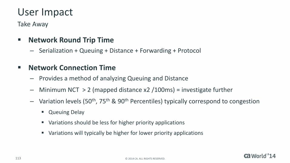
User Impact
Network Round Trip Time
– Serialization + Queuing + Distance + Forwarding + Protocol
Network Connection Time
– Provides a method of analyzing Queuing and Distance
– Minimum NCT > 2 (mapped distance x2 /100ms) = investigate further
– Variation levels (50th, 75th & 90th Percentiles) typically correspond to congestion
Queuing Delay
Variations should be less for higher priority applications
Variations will typically be higher for lower priority applications
Take Away
114 © 2014 CA. ALL RIGHTS RESERVED.
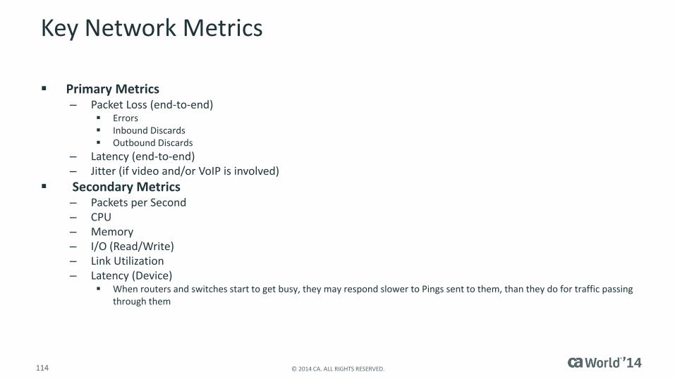
Key Network Metrics
Primary Metrics– Packet Loss (end-to-end)
Errors Inbound Discards Outbound Discards
– Latency (end-to-end)– Jitter (if video and/or VoIP is involved)
Secondary Metrics– Packets per Second – CPU– Memory– I/O (Read/Write)– Link Utilization– Latency (Device)
When routers and switches start to get busy, they may respond slower to Pings sent to them, than they do for traffic passing through them
115 © 2014 CA. ALL RIGHTS RESERVED.
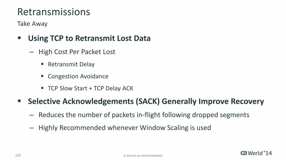
Retransmissions
Using TCP to Retransmit Lost Data
– High Cost Per Packet Lost
Retransmit Delay
Congestion Avoidance
TCP Slow Start + TCP Delay ACK
Selective Acknowledgements (SACK) Generally Improve Recovery
– Reduces the number of packets in-flight following dropped segments
– Highly Recommended whenever Window Scaling is used
Take Away

116 © 2014 CA. ALL RIGHTS RESERVED.
TCP Throughput
Throughput Cannot Exceed DBS/NRTT– Performance (Application Delivery) Improvements Demand at Least One:
Decrease in Packet Loss Increase Data Block Size (Application and/or TCP Window)
– Application: Decreases the Number of Application Turns– TCP Window: Increase the Number of Segments In-Flight
Decrease in Network Round Trip Time– Serialization Delay– Queuing Delay– Distance Delay– Forwarding Delay– Protocol Delay
TCP Delay ACK TCP Slow Start
Take Away
117 © 2014 CA. ALL RIGHTS RESERVED.
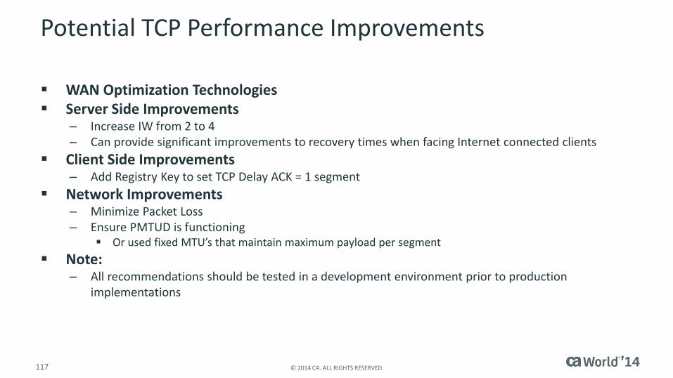
Potential TCP Performance Improvements
WAN Optimization Technologies Server Side Improvements
– Increase IW from 2 to 4– Can provide significant improvements to recovery times when facing Internet connected clients
Client Side Improvements– Add Registry Key to set TCP Delay ACK = 1 segment
Network Improvements– Minimize Packet Loss– Ensure PMTUD is functioning
Or used fixed MTU’s that maintain maximum payload per segment
Note: – All recommendations should be tested in a development environment prior to production
implementations
118 © 2014 CA. ALL RIGHTS RESERVED.
For More Information
To learn more about DevOps, please visit:
http://bit.ly/1wbjjqX
Insert appropriate screenshot and text overlayfrom following “More Info Graphics” slide here;
ensure it links to correct pageDevOps
119 © 2014 CA. ALL RIGHTS RESERVED.
For Informational Purposes Only
© 2014 CA. All rights reserved. All trademarks referenced herein belong to their respective companies.
This presentation provided at CA World 2014 is intended for information purposes only and does not form any type of warranty. Some of the specific slides with customer references relate to customer's specific use and experience of CA products and solutions so actual results may vary.
Terms of this Presentation