practical applications of radiative wireless power transfer · practical applications of radiative...
TRANSCRIPT

Practical Applications of Radiative
Wireless Power Transfer
Hubregt J. Visser
September 2016

Contents
1. Introduction
2. The Early History of RWPT
3. The Modern History of RWPT
4. RWPT Basics
5. Examples
6. Future Perspectives
7. Summary and Conclusions
/ Department of Electrical Engineering PAGE 119-9-2016
1. Introduction
/ Department of Electrical Engineering PAGE 219-9-2016
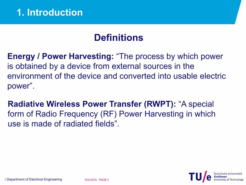
Energy / Power Harvesting: “The process by which power
is obtained by a device from external sources in the
environment of the device and converted into usable electric
power”.
Definitions
Radiative Wireless Power Transfer (RWPT): “A special
form of Radio Frequency (RF) Power Harvesting in which
use is made of radiated fields”.
1. Introduction (ctd.)
/ Department of Electrical Engineering PAGE 319-9-2016
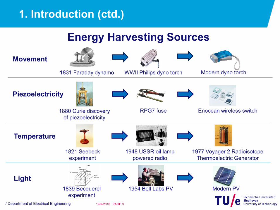
1831 Faraday dynamo WWII Philips dyno torch Modern dyno torch
1880 Curie discovery
of piezoelectricity
Enocean wireless switchRPG7 fuse
Movement
Piezoelectricity
1821 Seebeck
experiment
1948 USSR oil lamp
powered radio
Temperature
1977 Voyager 2 Radioisotope
Thermoelectric Generator
Light
1839 Becquerel
experiment
1954 Bell Labs PV Modern PV
Energy Harvesting Sources
1. Introduction (ctd.)
/ Department of Electrical Engineering PAGE 419-9-2016
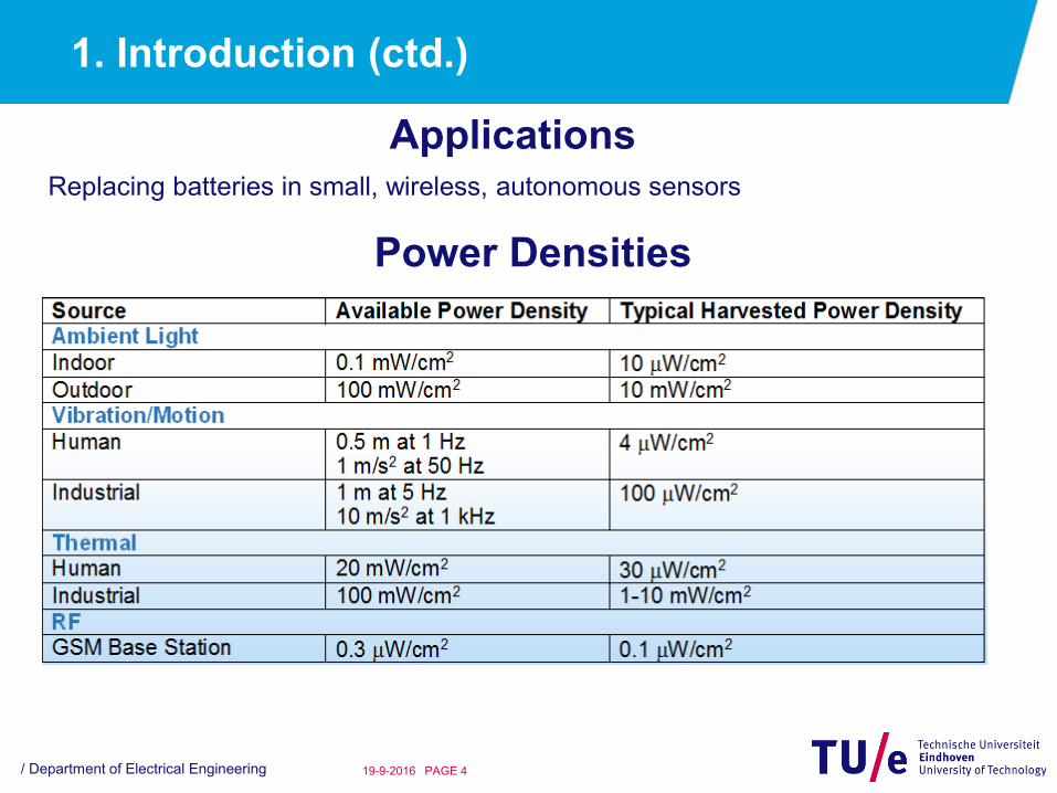
ApplicationsReplacing batteries in small, wireless, autonomous sensors
Power Densities
1. Introduction (ctd.)
/ Department of Electrical Engineering PAGE 519-9-2016
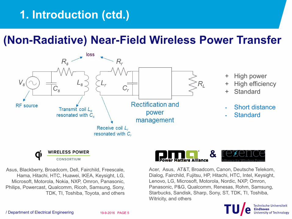
(Non-Radiative) Near-Field Wireless Power Transfer
+ High power
+ High efficiency
+ Standard
- Short distance
- Standard
&
Acer, Asus, AT&T, Broadcom, Canon, Deutsche Telekom,
Dialog, Fairchild, Fujitsu, HP, Hitachi, HTC, Intel, Keysight,
Lenovo, LG, Microsoft, Motorola, Nordic, NXP, Omron,
Panasonic, P&G, Qualcomm, Renesas, Rohm, Samsung,
Starbucks, Sandisk, Sharp, Sony, ST, TDK, TI, Toshiba,
Witricity, and others
Asus, Blackberry, Broadcom, Dell, Fairchild, Freescale,
Hama, Hitachi, HTC, Huawei, IKEA, Keysight, LG,
Microsoft, Motorola, Nokia, NXP, Omron, Panasonic,
Philips, Powercast, Qualcomm, Ricoh, Samsung, Sony,
TDK, TI, Toshiba, Toyota, and others

1. Introduction (ctd.)
/ Department of Electrical Engineering PAGE 619-9-2016
Radiative Far-Field Wireless Power Transfer
Ambient RF Energy
• Unintentional WPT or harvesting
• No influence on source and transmit antenna
Dedicated Transmit System
• Intentional WPT
• Access to source and transmit antenna
• Transmit power restrictions

1. Introduction (ctd.)
/ Department of Electrical Engineering PAGE 719-9-2016
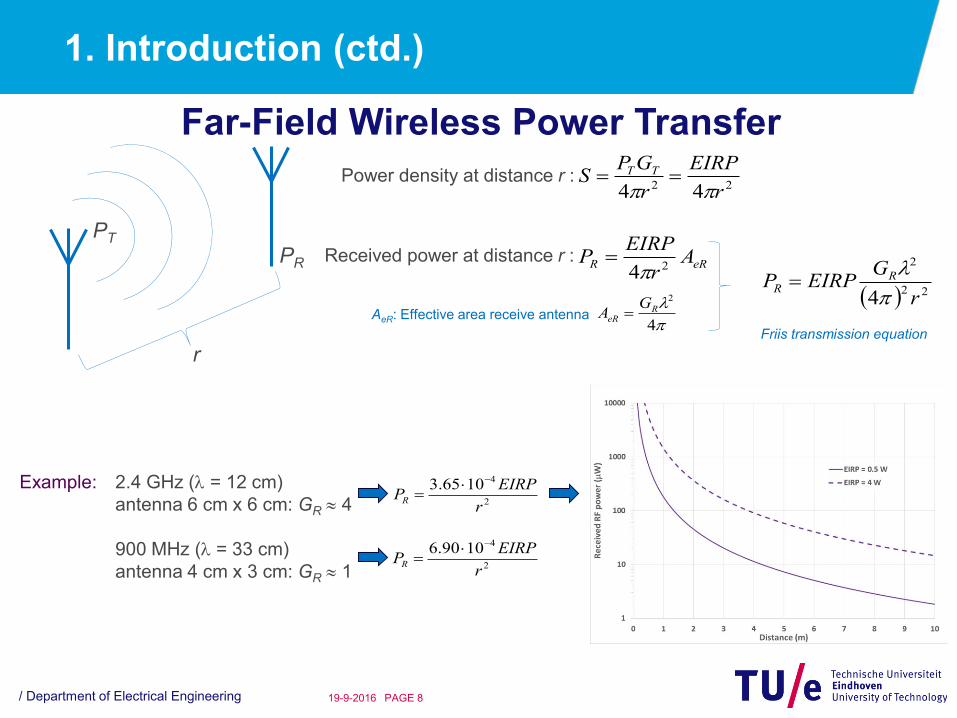
Far-Field Wireless Power Transfer
PT
Power density at distance r : 22 44 r
EIRP
r
GPS TT
PT : Transmit power
GT : Transmit antenna gain
Spherical spreading
EIRP : Effective Isotropic Radiated Power
Ambient (GSM900): 0.003 Wm-2
1. Introduction (ctd.)
/ Department of Electrical Engineering PAGE 819-9-2016
Far-Field Wireless Power Transfer
PT
PR
r
Power density at distance r : 22 44 r
EIRP
r
GPS TT
AeR: Effective area receive antenna
Received power at distance r : eRR A
r
EIRPP
24
4
2
ReR
GA
22
2
4 r
GEIRPP R
R
Friis transmission equation
Example: 2.4 GHz ( = 12 cm)
antenna 6 cm x 6 cm: GR 4
900 MHz ( = 33 cm)
antenna 4 cm x 3 cm: GR 1
2
41065.3
r
EIRPPR
2
41090.6
r
EIRPPR

2. The Early History of RWPT
/ Department of Electrical Engineering PAGE 919-9-2016
1901: Nikola Tesla creates the idea to wirelessly transmit and receive power

2. The Early History of RWPT (ctd.)
/ Department of Electrical Engineering PAGE 1019-9-2016
1931: Harrell Noble demonstrates Wireless Power Transfer
• 100MHz half-wavelength
dipoles
• Displaced 5 to 12 meters
• 15kW transmit power (!)
• Westinghouse laboratories
• Demonstrated at 1933-1934
Chicago World Fair

3. The Modern History of RWPT
/ Department of Electrical Engineering PAGE 1119-9-2016
1964: William Brown demonstrates a microwave powered model helicopter
• 5kW, 2.45GHz magnetron
• 3m diameter parabolic reflector
antenna
• 9m height
• 1.5m2 receive antenna
• 4480 diodes
• 270W dc power
• Raytheon Airborne Microwave
Platform (RAMP) project

3. The Modern History of RWPT
/ Department of Electrical Engineering PAGE 1219-9-2016
3. The Modern History of RWPT (ctd.)
/ Department of Electrical Engineering PAGE 1319-9-2016
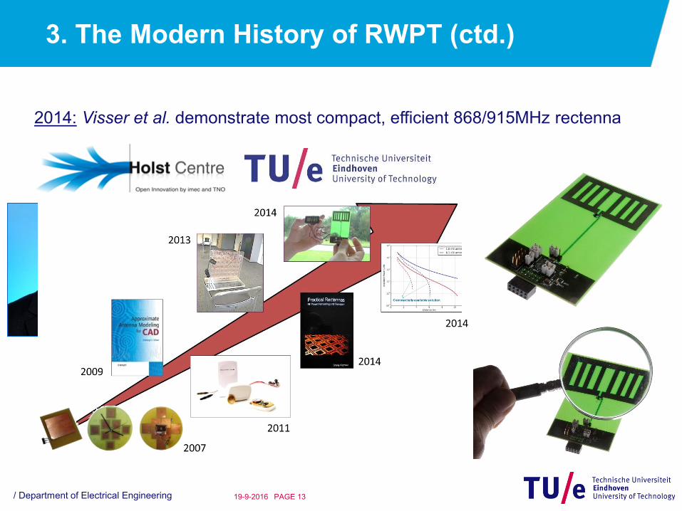
2014: Visser et al. demonstrate most compact, efficient 868/915MHz rectenna
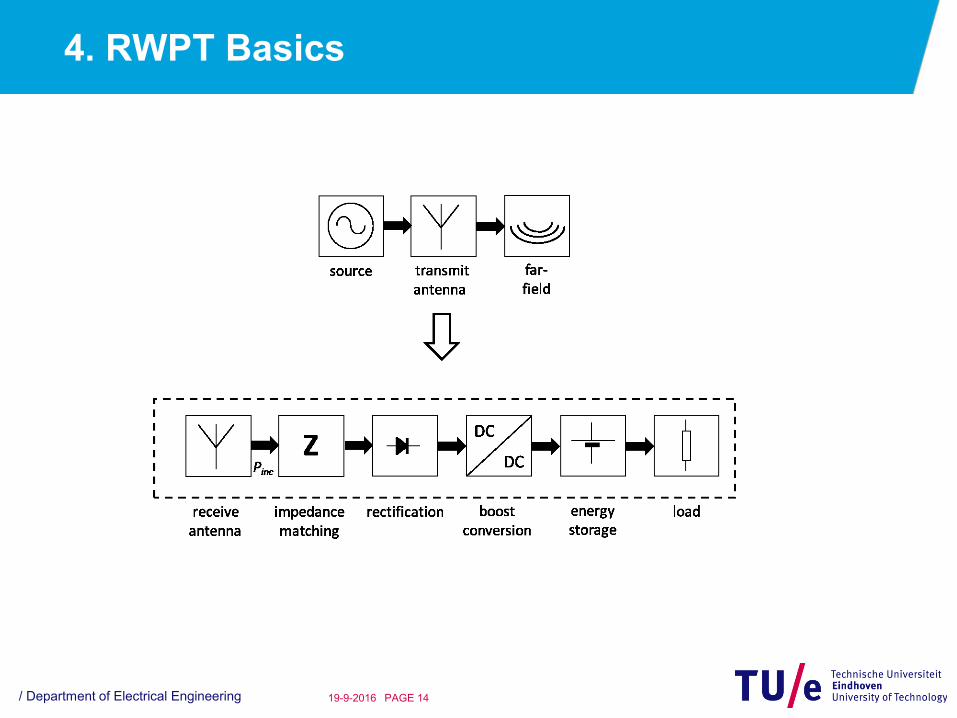
4. RWPT Basics
/ Department of Electrical Engineering PAGE 1419-9-2016

4. RWPT Basics (ctd.)
/ Department of Electrical Engineering PAGE 1519-9-2016
Antenna Radiation
E
H

4. RWPT Basics (ctd.)
/ Department of Electrical Engineering PAGE 1619-9-2016
Antenna Input Impedance
AAA jXRZ
LRA RRR
Reactive near field,
energy storage
Desired, radiationUndesired, loss (heat)
Tuned antenna: XA = 0. Low-loss materials: RL 0.
Maximum power delivered to load Rr if Rr RA:
Maximum power delivered to load Rr if Rr = RA:
A
AR
VP1
8
1 2
ArA
AA
RRR
RVP
1
2
12
2
Voltage reflection coefficient, looking into load:Ar
Ar
RR
RR
4. RWPT Basics (ctd.)
/ Department of Electrical Engineering PAGE 1719-9-2016
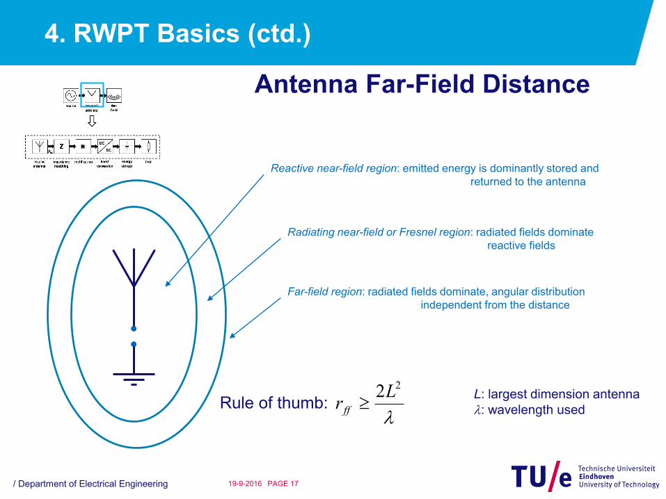
Antenna Far-Field Distance
Reactive near-field region: emitted energy is dominantly stored and
returned to the antenna
Radiating near-field or Fresnel region: radiated fields dominate
reactive fields
Far-field region: radiated fields dominate, angular distribution
independent from the distance
Rule of thumb:
22Lr ff
L: largest dimension antenna
: wavelength used

4. RWPT Basics (ctd.)
/ Department of Electrical Engineering PAGE 1819-9-2016
Antenna Directivity and Gain

4. RWPT Basics (ctd.)
/ Department of Electrical Engineering PAGE 1919-9-2016
Friis Equation
Assume transmit antenna to be uniform radiator. Then power
density at distance r:
24 r
PrS T
spherical spreading
In reality antenna has gain GT: 24 r
GPrS TT
Receive antenna intercepts power equal to the power density times the effective aperture Ae:
24 r
AGPArSrP eTTeR
With:
4
2
Re
GA
22
2
4,
r
GGPrP RTTR
PTGT is Effective Isotropic Radiated Power
4. RWPT Basics (ctd.)
/ Department of Electrical Engineering PAGE 2019-9-2016
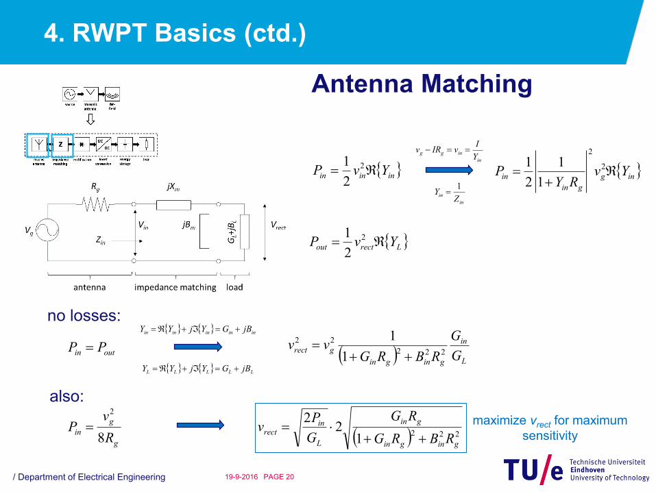
Antenna Matching
ininin YvP 2
2
1 ing
gin
in YvRY
P
2
2
1
1
2
1in
inggY
IvIRv
in
inZ
Y1
Lrectout YvP 2
2
1
no losses:
outin PP
ininininin jBGYjYY
LLLLL jBGYjYY
L
in
gingin
grectG
G
RBRGvv
222
22
1
1
also:
g
g
inR
vP
8
2
2221
22
gingin
gin
L
inrect
RBRG
RG
G
Pv
maximize vrect for maximum
sensitivity
4. RWPT Basics (ctd.)
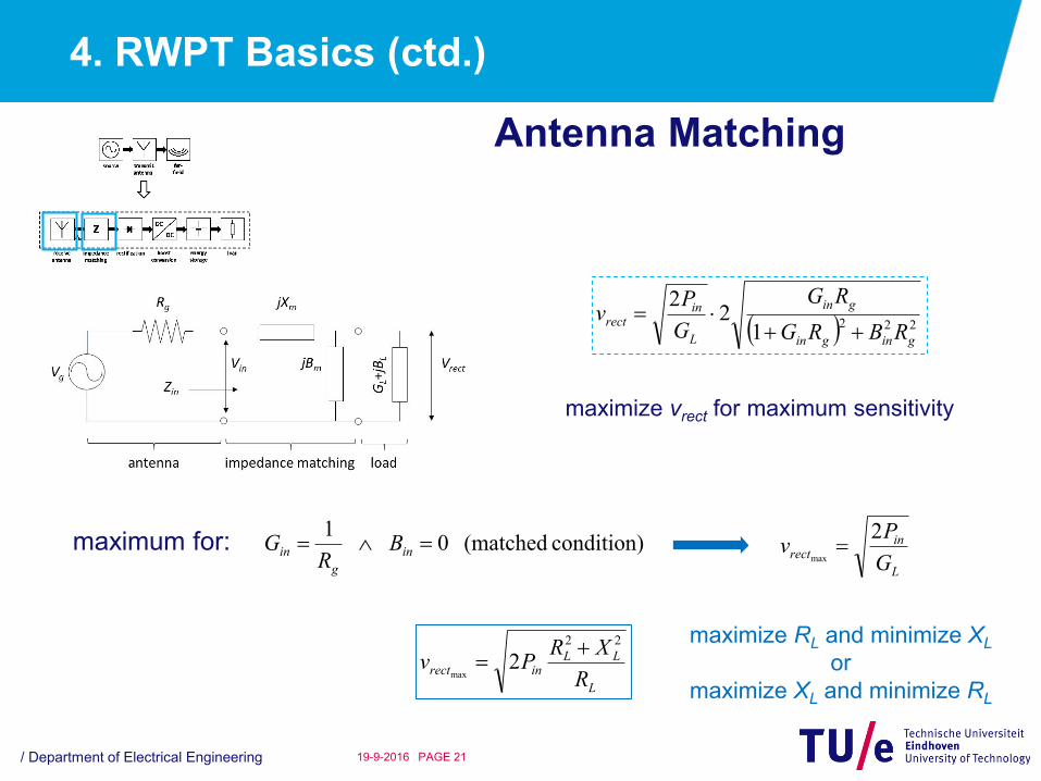
/ Department of Electrical Engineering PAGE 2119-9-2016
Antenna Matching
2221
22
gingin
gin
L
inrect
RBRG
RG
G
Pv
maximize vrect for maximum sensitivity
maximum for: condition) (matched 0 1
in
g
in BR
G
L
inrect
G
Pv
2max
L
LLinrect
R
XRPv
22
2max
maximize RL and minimize XL
or
maximize XL and minimize RL

4. RWPT Basics (ctd.)
/ Department of Electrical Engineering PAGE 2219-9-2016
Antenna Design
Any antenna textbook, but preferably:

4. RWPT Basics (ctd.)
/ Department of Electrical Engineering PAGE 2319-9-2016
Rectifier
dcL
sgVnR
RR
sL
dcincg e
IR
VPR
nII
1
0 18
R.G. Harrison and X. Le Polozec, “Nonsquarelaw Behavior of Diode Detectors Analyzed by the Ritz-Galerkin method”, IEEE Transactions on
Microwave Theory and Techniques, Vol. 42, No. 5, pp. 840-846, May 1994.
Zero-order Bessel function of the first kind
Diode ideality factor
Generator resistance
Available RF input power
DC output voltage
Load resistance
Diode saturation current
Diode series resistance
kT
q
Electron charge
Boltzmann’s constant Temperature
Output voltage

4. RWPT Basics (ctd.)
/ Department of Electrical Engineering PAGE 2419-9-2016
Rectifier
Input Impedance
RLoad = 2RLeff Fundamental harmonic of diode’s current is ~ twice dc load current
4. RWPT Basics (ctd.)
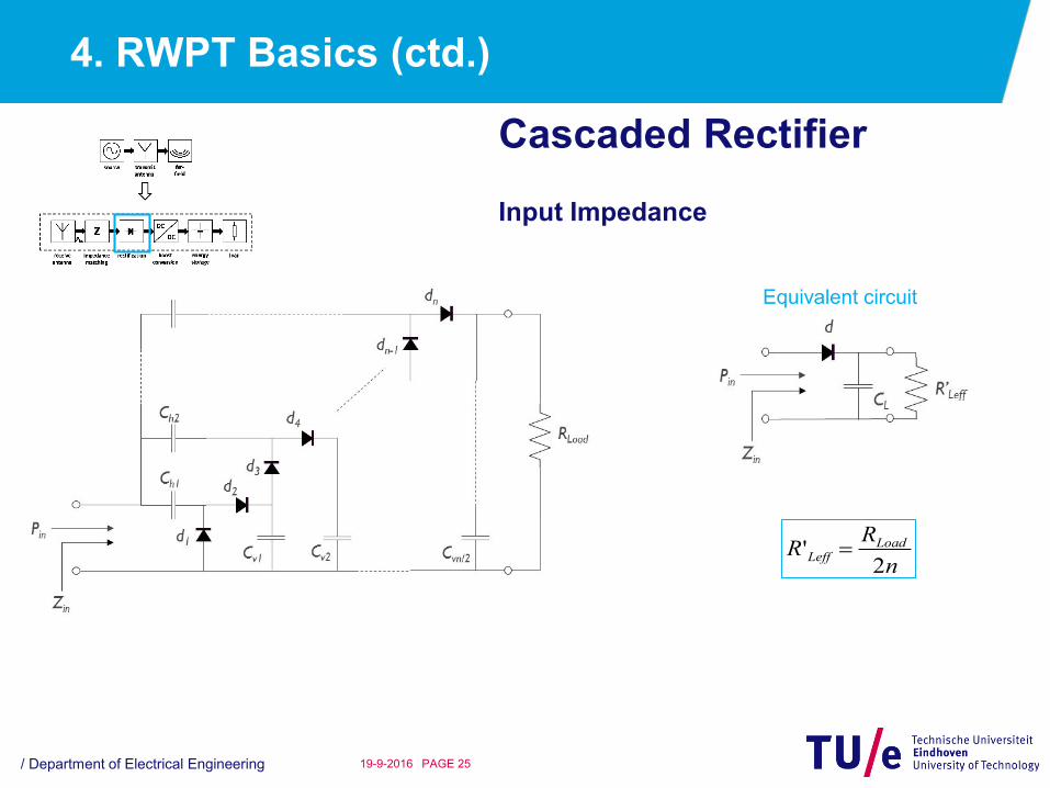
/ Department of Electrical Engineering PAGE 2519-9-2016
Cascaded Rectifier
Input Impedance
Equivalent circuit
n
RR LoadLeff
2'
4. RWPT Basics (ctd.)
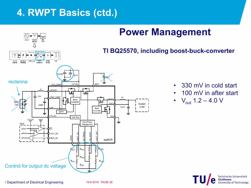
/ Department of Electrical Engineering PAGE 2619-9-2016
Power Management
TI BQ25570, including boost-buck-converter
• 330 mV in cold start
• 100 mV in after start
• Vout 1.2 – 4.0 V
rectenna
Control for output dc voltage
5. Examples
/ Department of Electrical Engineering PAGE 2719-9-2016
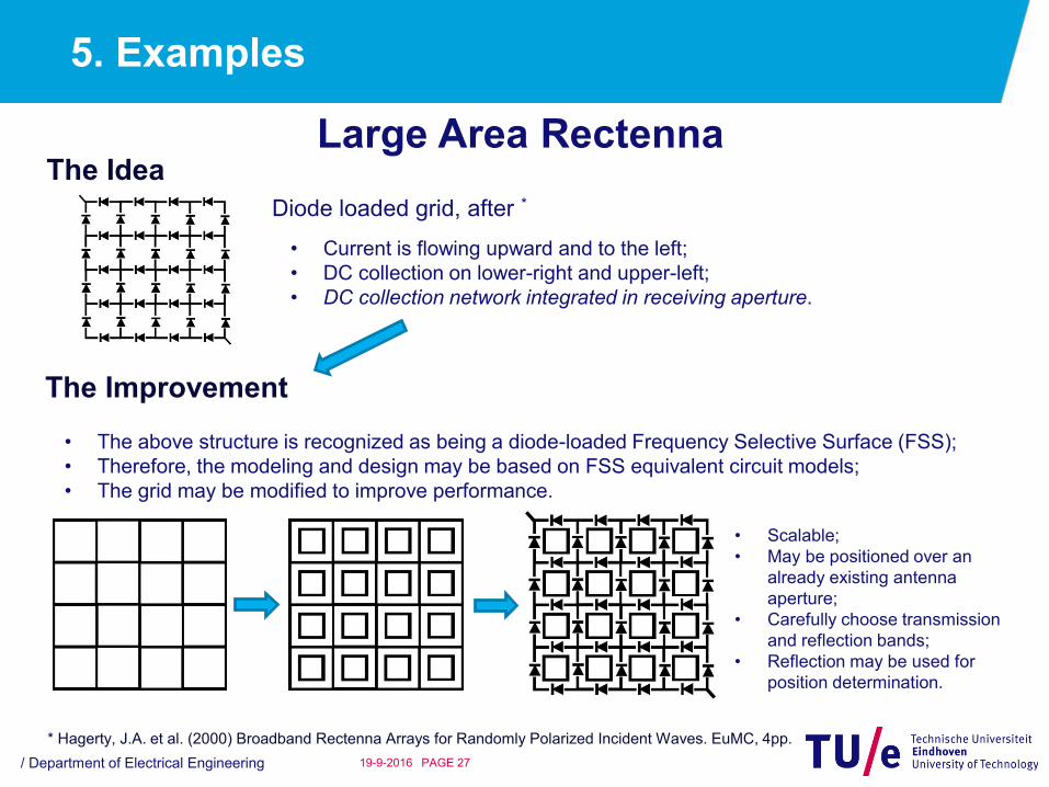
Large Area RectennaThe Idea
Diode loaded grid, after *
* Hagerty, J.A. et al. (2000) Broadband Rectenna Arrays for Randomly Polarized Incident Waves. EuMC, 4pp.
• Current is flowing upward and to the left;
• DC collection on lower-right and upper-left;
• DC collection network integrated in receiving aperture.
The Improvement
• The above structure is recognized as being a diode-loaded Frequency Selective Surface (FSS);
• Therefore, the modeling and design may be based on FSS equivalent circuit models;
• The grid may be modified to improve performance.
• Scalable;
• May be positioned over an
already existing antenna
aperture;
• Carefully choose transmission
and reflection bands;
• Reflection may be used for
position determination.
5. Examples (ctd.)
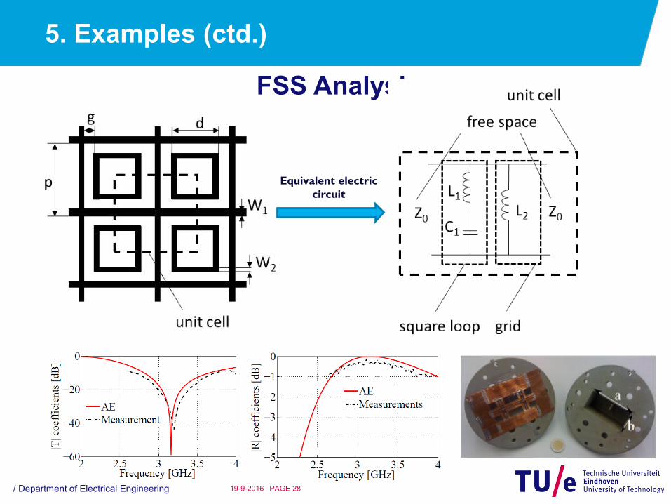
/ Department of Electrical Engineering PAGE 2819-9-2016
FSS Analysis
Equivalent electric
circuit
5. Examples (ctd.)
/ Department of Electrical Engineering PAGE 2919-9-2016
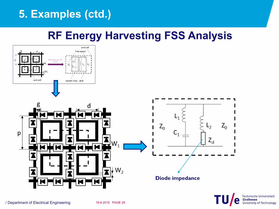
RF Energy Harvesting FSS Analysis
Diode impedance
5. Examples (ctd.)
/ Department of Electrical Engineering PAGE 3019-9-2016
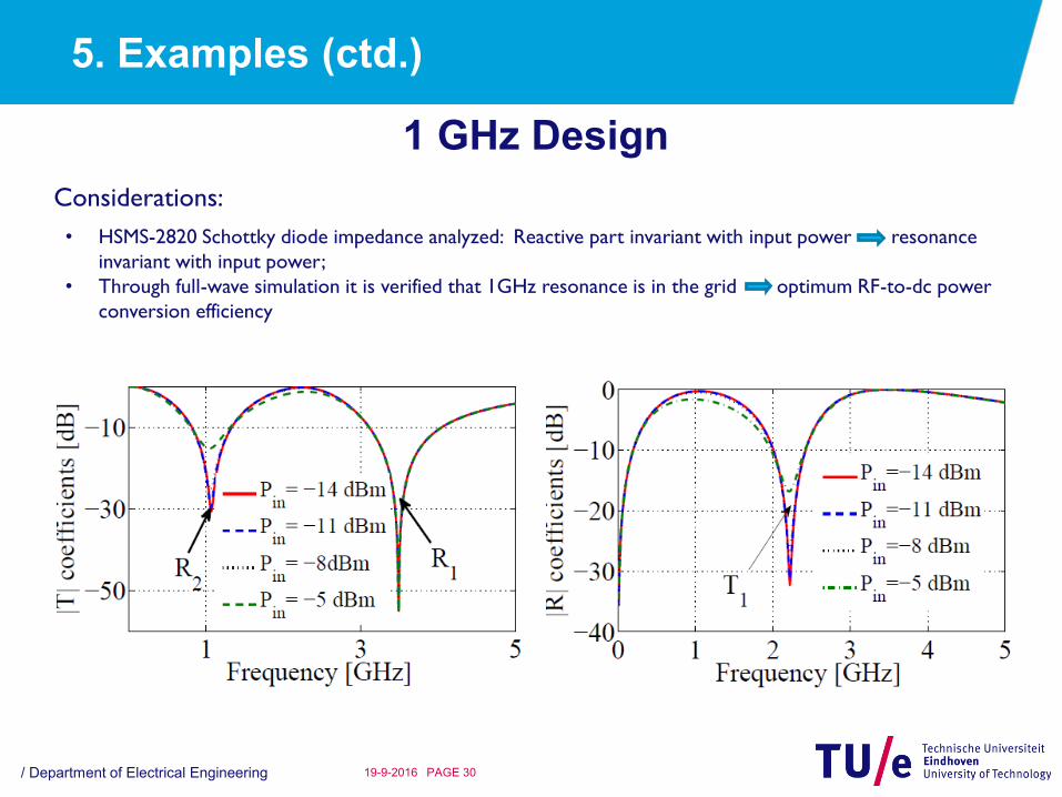
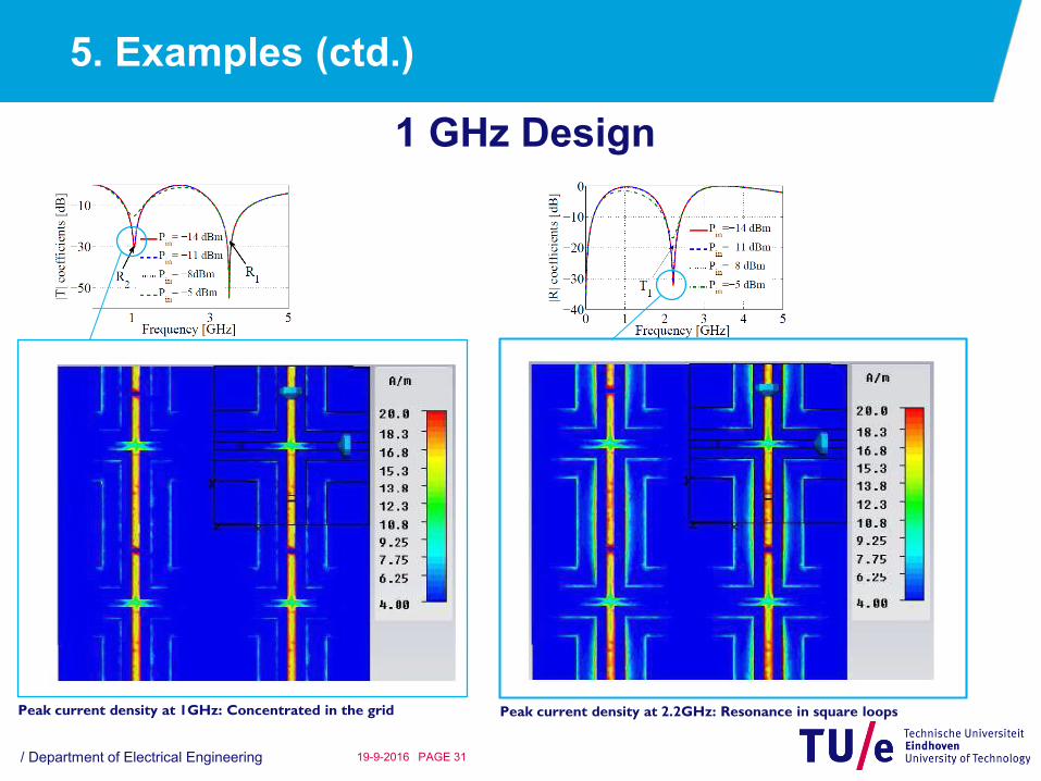
1 GHz Design
Considerations:
• HSMS-2820 Schottky diode impedance analyzed: Reactive part invariant with input power resonance
invariant with input power;
• Through full-wave simulation it is verified that 1GHz resonance is in the grid optimum RF-to-dc power
conversion efficiency
5. Examples (ctd.)
/ Department of Electrical Engineering PAGE 3119-9-2016
1 GHz Design
Peak current density at 1GHz: Concentrated in the grid Peak current density at 2.2GHz: Resonance in square loops

5. Examples (ctd.)
/ Department of Electrical Engineering PAGE 3219-9-2016
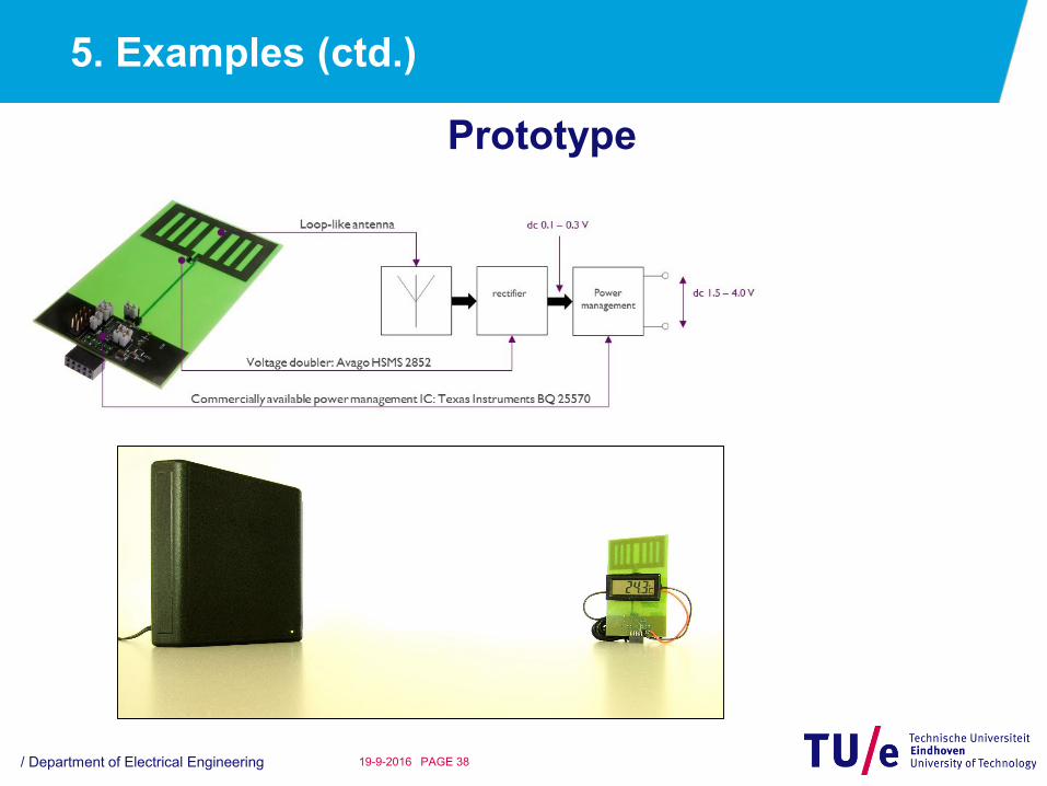
Prototype
5. Examples (ctd.)
/ Department of Electrical Engineering PAGE 3319-9-2016
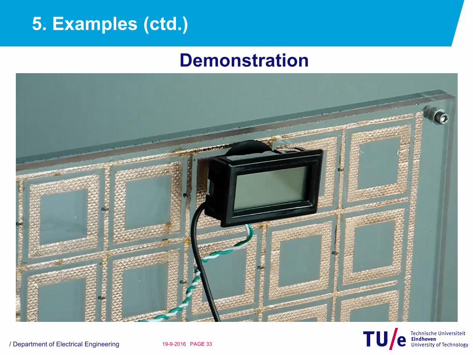
Demonstration

5. Examples (ctd.)
/ Department of Electrical Engineering PAGE 3419-9-2016
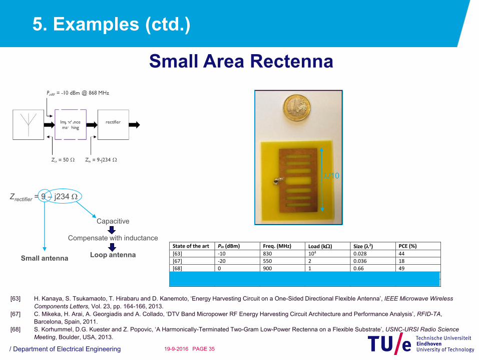
Small Area Rectenna
State of the art Pin (dBm) Freq. (MHz) Load (k) Diode(s) PCE (%)
[61] -10 866.5 3 HSMS285C 24
[62] 4.3 870 1 HSMS285X 50
[63] -10 830 104 HSMS286Y 44
[64] -20 850 - Skyworks SMS7630 15
[65] -10 950 0.13 Toshiba 1SS315 40
[66] -9 915 2.2 Skyworks SMS7630 37
This work -10 -20
868 868
10 10
HSMS2852 HSMS2852
50 32
[61] D. De Donno, L. Catarinucci and L. Tarricone, ‘An UHF RFID Energy-Harvesting System Enhanced by a DC-DC Charge Pump in Silicon-On-Insulator
Technology’, IEEE Microwave Wireless Components Letters, Vol. 23, pp. 315-317, 2013.
[62] G. Monti, L. Corchia and L. Tarricone, ‘UHF Wearable Rectenna on Textile Materials’, IEEE Transactions on Antennas and Propagation, Vol. 61, pp. 3869-3873,
2013.
[63] H. Kanaya, S. Tsukamaoto, T. Hirabaru and D. Kanemoto, ‘Energy Harvesting Circuit on a One-Sided Directional Flexible Antenna’, IEEE Microwave Wireless
Components Letters, Vol. 23, pp. 164-166, 2013.
[64] A. Georgiadis, A. Collado, S. Via and C. Menses, ‘Flexible Hybrid Solar/EM Energy Harvester for Autonomous Sensors’, IEEE MTT-S International Microwave
Symposium, Baltimore, USA, 2011.
[65] K. Ogawa, K. Ozaki, M. Yamada and K. Honda, ‘High Efficiency Small-Sized Rectenna Using a High-Q LC Resonator for Long Distance WPT at 950 MHz’, IEEE
MTT-S International Microwave Symposium, Nanjing, China, 2012.
[66] K. Niotaki, S. Kim, S. Jeong, A. Collado, A. Georgiadis and M. Tentzeris, ‘A Compact Dual-Band Rectenna Using Slot-Loaded Dual Band Folded Dipole Antenna’,
IEEE Antennas and Wireless Propagation Letters, Vol. 12, pp. 1634-1637, 2013.
inRF
dc
P
PPCE
5. Examples (ctd.)
/ Department of Electrical Engineering PAGE 3519-9-2016
Small Area Rectenna
Zrectifier = 9 – j234
Capacitive
Compensate with inductance
Loop antennaSmall antenna
/10
State of the art Pin (dBm) Freq. (MHz) Load (k) Size (2) PCE (%)
[63] -10 830 104 0.028 44
[67] -20 550 2 0.036 18
[68] 0 900 1 0.66 49
This work -10 868 10 0.028 55
-20 868 10 0.028 34
[63] H. Kanaya, S. Tsukamaoto, T. Hirabaru and D. Kanemoto, ‘Energy Harvesting Circuit on a One-Sided Directional Flexible Antenna’, IEEE Microwave Wireless
Components Letters, Vol. 23, pp. 164-166, 2013.
[67] C. Mikeka, H. Arai, A. Georgiadis and A. Collado, ‘DTV Band Micropower RF Energy Harvesting Circuit Architecture and Performance Analysis’, RFID-TA,
Barcelona, Spain, 2011.
[68] S. Korhummel, D.G. Kuester and Z. Popovic, ‘A Harmonically-Terminated Two-Gram Low-Power Rectenna on a Flexible Substrate’, USNC-URSI Radio Science
Meeting, Boulder, USA, 2013.

5. Examples (ctd.)
/ Department of Electrical Engineering PAGE 3619-9-2016
Circuit Test
Array of load resistors
connected to BJTs that are
operated as switches
Replacing antenna during
tests for ensuring a stable
signal

5. Examples (ctd.)
/ Department of Electrical Engineering PAGE 3719-9-2016
Circuit Test
5. Examples (ctd.)
/ Department of Electrical Engineering PAGE 3819-9-2016
Prototype
5. Examples (ctd.)
/ Department of Electrical Engineering PAGE 3919-9-2016
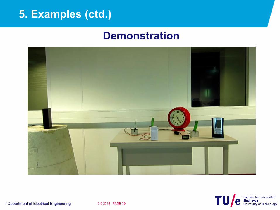
Demonstration
6. Future Perspectives
/ Department of Electrical Engineering PAGE 4019-9-2016
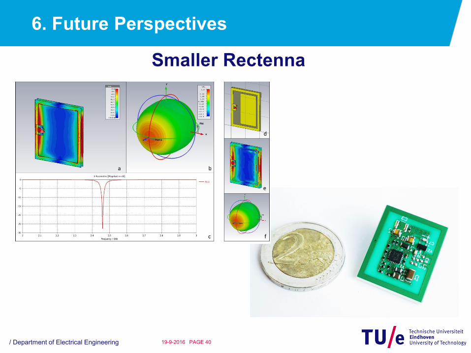
Smaller Rectenna
6. Future Perspectives
/ Department of Electrical Engineering PAGE 4119-9-2016
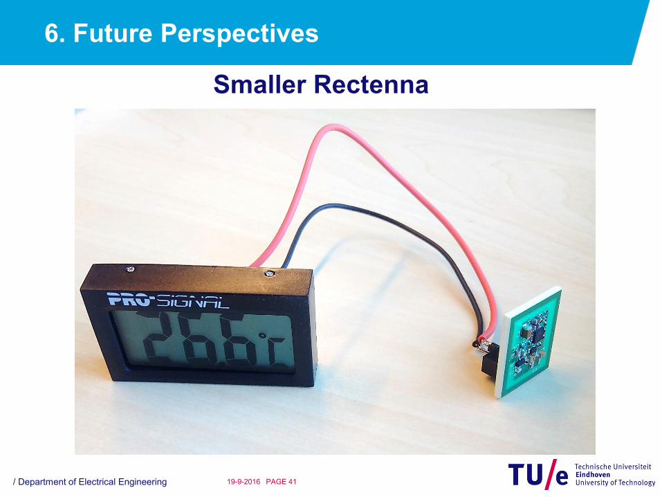
Smaller Rectenna

6. Future Perspectives (Ctd)
/ Department of Electrical Engineering PAGE 4219-9-2016
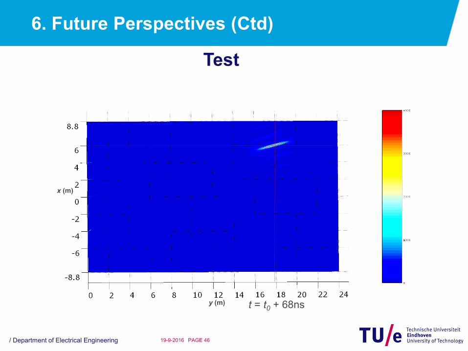
More Power
Basic Idea

6. Future Perspectives (Ctd)
/ Department of Electrical Engineering PAGE 4319-9-2016
Test
t = t0 + 10ns
x (m)
y (m)
6. Future Perspectives (Ctd)
/ Department of Electrical Engineering PAGE 4419-9-2016
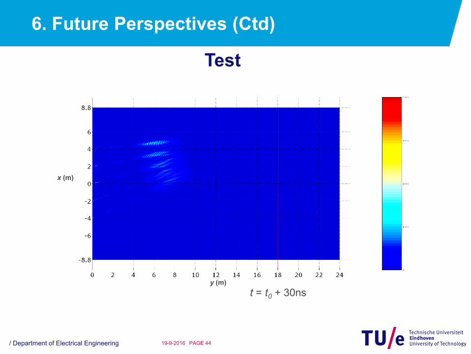
Test
t = t0 + 30ns
x (m)
y (m)

6. Future Perspectives (Ctd)
/ Department of Electrical Engineering PAGE 4519-9-2016
Test
t = t0 + 50ns
x (m)
y (m)
6. Future Perspectives (Ctd)
/ Department of Electrical Engineering PAGE 4619-9-2016
Test
t = t0 + 68ns
x (m)
y (m)

6. Future Perspectives (Ctd)
/ Department of Electrical Engineering PAGE 4719-9-2016
Test
t = t0 + 90ns
x (m)
y (m)
Conclusion
/ Department of Electrical Engineering PAGE 4819-9-2016
• For practical far-field WPT dc voltage is a challenge;
• Sufficient voltage may be created by enlarging the
receiving aperture;
• For small sensors, application of a voltage boost and
power management circuit is advised;
• Through careful co-design of rectifier, antenna,
matching circuits and power management circuit
practical WPT becomes feasible;
• Periodic loading will make WPT over distances in
excess of 10m possible;
• Transient WPT will make large power WPT feasible.