ppt templateiom.invensys.com/en/usergroupspresentationsdallas2013...drum/separator feeds tab: inlet...
TRANSCRIPT

Slide 1

SS TSS-04 DYNSIM Best PracticesPresented at User Group 2013
Ted FediwPrincipal Technical SupportEngineer1-800-746-7241, option [email protected]
@InvensysOpsMgmt / #SoftwareRevolution
/InvensysVideos
social.invensys.com
© 2013 Invensys. All Rights Reserved. The names, logos, and taglines identifying the products and services of Invensys are proprietary marks of Invensys or its subsidiaries.All third party trademarks and service marks are the proprietary marks of their respective owners.
Presented at User Group 2013
Ted FediwPrincipal Technical SupportEngineer1-800-746-7241, option [email protected]
/InvensysOpsMgmt
/Group/DYNSIM

DYNSIM Best Practices – PresentationOutline• New Simulation Setup
• Thermodynamics and Components
• Flash Methods
• Header
• Drum/Separator
• Pump/Compressor
• Distillation Column
• Heat Exchanger
• Multi-Pass Heat Exchanger
• Debugging
Slide 3
• New Simulation Setup
• Thermodynamics and Components
• Flash Methods
• Header
• Drum/Separator
• Pump/Compressor
• Distillation Column
• Heat Exchanger
• Multi-Pass Heat Exchanger
• Debugging

DYNSIM Best Practices – NewSimulation Set-up• Plan your simulation
• Data gathering (at a minimum: P&IDs, Heat and Material Balance,Equipment data sheets).
• Naming conventions (equipment, streams)
• What is in scope, not in scope (not every equipment on a P&IDneeds to be simulated)
• Flow sheet break-up
• Engine break-up (for larger simulations)
Slide 4
• Plan your simulation
• Data gathering (at a minimum: P&IDs, Heat and Material Balance,Equipment data sheets).
• Naming conventions (equipment, streams)
• What is in scope, not in scope (not every equipment on a P&IDneeds to be simulated)
• Flow sheet break-up
• Engine break-up (for larger simulations)

DYNSIM Best Practices – NewSimulation Set-up• Stream Send/Stream Receive:
• Starting with DYNSIM 4.2, process data could be transferredbetween engines with these objects.
• Ease the need for many entries in the cross-reference table, such aswith large simulations with many components and flow sheets.
• Try to create your engine splits with a large volume downstream(such as a column) and a flow device with a decent pressure dropupstream.
Slide 5
• Stream Send/Stream Receive:
• Starting with DYNSIM 4.2, process data could be transferredbetween engines with these objects.
• Ease the need for many entries in the cross-reference table, such aswith large simulations with many components and flow sheets.
• Try to create your engine splits with a large volume downstream(such as a column) and a flow device with a decent pressure dropupstream.

DYNSIM Demo
(example flow sheet break-up, Stream Send/Stream Receive)
Slide 6

DYNSIM Best Practices – NewSimulation Set-up• Data requirements:
P&IDs
Slide 7

DYNSIM Best Practices – NewSimulation Set-up• Data requirements (P&IDs):
• Try to set up with a 1 to 1 relationship between the number of flowsheets and the number of P&IDs.
• Facilitates easier understanding of the process and model testing.
• Facilitates engine break-up if needed (large simulation).
• Not everything needs to be simulated.
Examples:
block valves in series, pipes.
Slide 8
• Data requirements (P&IDs):
• Try to set up with a 1 to 1 relationship between the number of flowsheets and the number of P&IDs.
• Facilitates easier understanding of the process and model testing.
• Facilitates engine break-up if needed (large simulation).
• Not everything needs to be simulated.
Examples:
block valves in series, pipes.

DYNSIM Demo (flow sheets)
Slide 9

DYNSIM Best Practices – NewSimulation Set-up• Data requirements (Heat and Material Balance):
• PRO/II output provides most of this information (components,thermodynamics, stream information)
• The steady state heat and material balance serves as the referencepoint for the design check.
• You need a design basis for a dynamic simulation. DYNSIM is not adesign tool.
Slide 10
• Data requirements (Heat and Material Balance):
• PRO/II output provides most of this information (components,thermodynamics, stream information)
• The steady state heat and material balance serves as the referencepoint for the design check.
• You need a design basis for a dynamic simulation. DYNSIM is not adesign tool.

DYNSIM Best Practices – NewSimulation Set-up• Data requirements (Equipment Data):
• Examples:
• Heat exchanger data sheets (heat transfer area, first pass heat transfercoefficients)
• Control valve data sheets (Cv, trim types, valve travel times)
• Drum (dimensions, port locations)
• Towers (dimensions, tray details, port locations)
• Pumps/Compressors (performance curves)
Slide 11
• Data requirements (Equipment Data):
• Examples:
• Heat exchanger data sheets (heat transfer area, first pass heat transfercoefficients)
• Control valve data sheets (Cv, trim types, valve travel times)
• Drum (dimensions, port locations)
• Towers (dimensions, tray details, port locations)
• Pumps/Compressors (performance curves)

DYNSIM Best Practices – Componentsand ThermoComponent Selection:
Slide 12

DYNSIM Best Practices – Componentsand ThermoComponent Selection:
Where do you get the components?
From your PRO/II Heat and Material Balance
Slide 13

DYNSIM Best Practices – Componentsand ThermoThermo Method Selection:
Slide 14

DYNSIM Best Practices – Componentsand ThermoThermo Method Selection:
Where do you get the Thermo method?
From your PRO/II Heat and Material Balance
Slide 15

DYNSIM Best Practices – Componentsand ThermoThermo Method Selection:
General guidelines:
Different methods should not normally be selected for Liquid 1 andLiquid 2. In a VLLE flash there is no actual distinction between the twoliquids. If the Liquid 1 phase should happen to vanish during a dynamictransient, then Liquid 2, being the only liquid, will appear in the Liquid1 slot. Having different methods for each will produce inconsistentresults.
The one exception to this rule is Free Water Decant. In this case only,the Liquid 2 method may be set to Ind. Form Steam Tables 1997 asshown below (Fig. 1.2). This is permissible because the Free WaterDecant flash constrains the free water phase so that it can only appearin the Liquid 2 slot.
Slide 16
Thermo Method Selection:
General guidelines:
Different methods should not normally be selected for Liquid 1 andLiquid 2. In a VLLE flash there is no actual distinction between the twoliquids. If the Liquid 1 phase should happen to vanish during a dynamictransient, then Liquid 2, being the only liquid, will appear in the Liquid1 slot. Having different methods for each will produce inconsistentresults.
The one exception to this rule is Free Water Decant. In this case only,the Liquid 2 method may be set to Ind. Form Steam Tables 1997 asshown below (Fig. 1.2). This is permissible because the Free WaterDecant flash constrains the free water phase so that it can only appearin the Liquid 2 slot.

DYNSIM Best Practices – Componentsand ThermoExample Free Water Decant Method:
Slide 17

DYNSIM Best Practices – Componentsand Thermo• Carefully consider the components required for your simulation.
This should be done in the planning stages before you begin yoursimulation. If you have to add components after simulation buildinghas begun, it might give you headaches.
• Also, carefully consider the number of components needed. Toomany components will bog down your simulation.
• There is a balance between these considerations.
Slide 18
• Carefully consider the components required for your simulation.This should be done in the planning stages before you begin yoursimulation. If you have to add components after simulation buildinghas begun, it might give you headaches.
• Also, carefully consider the number of components needed. Toomany components will bog down your simulation.
• There is a balance between these considerations.
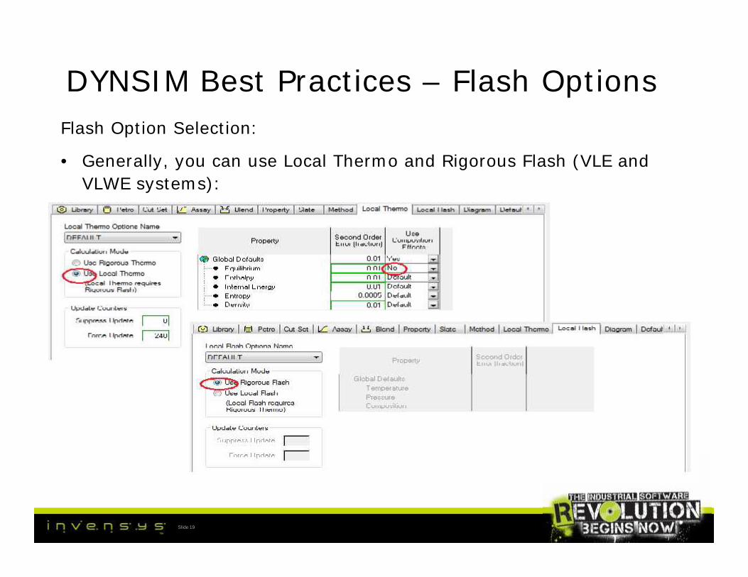
DYNSIM Best Practices – Flash OptionsFlash Option Selection:
• Generally, you can use Local Thermo and Rigorous Flash (VLE andVLWE systems):
Slide 19

DYNSIM Best Practices – Flash OptionsFlash Option Selection:
• Occasionally, you use Rigorous Thermo and Local Flash (VLLE):
Slide 20

DYNSIM Best Practices – Flash OptionsFlash Option Selection:
Slide 21

DYNSIM Best Practices – Flash• Avoid using Liquid only or Vapor only Flash option
• Check for simple flash convergence problems with the FlashStatistics monitor:
Slide 22

DYNSIM Best Practices – Header
• Header is a pressure node used to simulate flow mixing, splitting,and pipe dynamics.
• Compressible and Incompressible holdup dynamics are availableoptions.
• Heat transfer from fluid to metal and metal to surroundings isaccounted for.
• Heat can be added thru external sources (e.g. heat stream)
Slide 23
• Header is a pressure node used to simulate flow mixing, splitting,and pipe dynamics.
• Compressible and Incompressible holdup dynamics are availableoptions.
• Heat transfer from fluid to metal and metal to surroundings isaccounted for.
• Heat can be added thru external sources (e.g. heat stream)
DYNSIM Best Practices – Header
• Multiple inlets and outlets are entered on the GUI.
• The volume of the header is based on the piping volume. Usersshould develop a reasonable estimate of the actual volume; thedefault value of 1 m3 (35.3 ft3), located on the Basic Tab of theData Entry window, is almost never correct. If users do some upfront engineering to calculate realistic header volumes, it will saveheadaches later, especially during dynamic testing.
Slide 24
• Multiple inlets and outlets are entered on the GUI.
• The volume of the header is based on the piping volume. Usersshould develop a reasonable estimate of the actual volume; thedefault value of 1 m3 (35.3 ft3), located on the Basic Tab of theData Entry window, is almost never correct. If users do some upfront engineering to calculate realistic header volumes, it will saveheadaches later, especially during dynamic testing.

DYNSIM Demo (actual header)
Slide 25

DYNSIM Best Practices – Header
Slide 26

DYNSIM Best Practices – HeaderHeat transfer tab: generally, keep the default values at initial
configuration; adjust as needed during dynamic testing, especiallystart-up and shutdown.
Slide 27

DYNSIM Best Practices – HeaderSolution options: Always use Simultaneous.
Slide 28

DYNSIM Best Practices – HeaderInitialization: always initialize your headers! If you do not, thefirst time a header sees flow, the composition will be initialized toequimolar components; ambient temperature and pressure.
Slide 29

DYNSIM Demo (example of Source Initializations)
Slide 30

DYNSIM Best Practices –Drum/Separator• Drum and Separator are similar; both can simulate two or three
phase separation vessels; the difference is that the separator has aseparate holdup for each liquid phase.
• In most cases, Drum is sufficient and preferred for simulation.
• Separator can be used for situations where there are two liquidphases with a weir overflow (example: a Quench Settler in anethylene plant).
• Possible orientations: horizontal, vertical, horizontal with boot,vertical with boot, spherical, user-defined.
• Additional orientations for separator: horizontal with weir, verticalwith weir.
Slide 31
• Drum and Separator are similar; both can simulate two or threephase separation vessels; the difference is that the separator has aseparate holdup for each liquid phase.
• In most cases, Drum is sufficient and preferred for simulation.
• Separator can be used for situations where there are two liquidphases with a weir overflow (example: a Quench Settler in anethylene plant).
• Possible orientations: horizontal, vertical, horizontal with boot,vertical with boot, spherical, user-defined.
• Additional orientations for separator: horizontal with weir, verticalwith weir.

DYNSIM Best Practices –Drum/SeparatorBasic Tab: enter info such as diameter, length, which are obtained
from the equipment data sheet.
Slide 32

DYNSIM Best Practices –Drum/SeparatorHeat Transfer Tab: use the default values to start. These values can
be adjusted during dynamic testing.
Slide 33

DYNSIM Best Practices –Drum/SeparatorFeeds Tab:
Inlet Feed Stream - feed port height is used in calculation of statichead correction of feed stream pressure. Default value of thisparameter is 0. The feed port diameter is used to determine thestream properties for reverse flow case when there is a fluidinterface at the port. Default value is 0.1, which can be used inmost cases.
Vapor Feed Stream - The vapor port diameter is used to determinethe stream properties for reverse flow case when the Drum is closeto liquid filled with fluid interface at the port. Default value is 0.1,which can be used for most cases.
Slide 34
Feeds Tab:
Inlet Feed Stream - feed port height is used in calculation of statichead correction of feed stream pressure. Default value of thisparameter is 0. The feed port diameter is used to determine thestream properties for reverse flow case when there is a fluidinterface at the port. Default value is 0.1, which can be used inmost cases.
Vapor Feed Stream - The vapor port diameter is used to determinethe stream properties for reverse flow case when the Drum is closeto liquid filled with fluid interface at the port. Default value is 0.1,which can be used for most cases.

DYNSIM Best Practices –Drum/SeparatorFeeds Tab:
Liquid Feed Stream - The liquid port diameter is used to determinethe stream properties for reverse flow case when the Drum has fluidinterface at the port. Default value is 0.1, which can be used formost cases.
Liquid2 Feed Stream - The liquid2 port diameter is used todetermine the stream properties for reverse flow case when theDrum is close to empty with fluid interface at the port. Default valueis 0.1, which can be used for most cases.
Slide 35
Feeds Tab:
Liquid Feed Stream - The liquid port diameter is used to determinethe stream properties for reverse flow case when the Drum has fluidinterface at the port. Default value is 0.1, which can be used formost cases.
Liquid2 Feed Stream - The liquid2 port diameter is used todetermine the stream properties for reverse flow case when theDrum is close to empty with fluid interface at the port. Default valueis 0.1, which can be used for most cases.

DYNSIM Best Practices –Drum/SeparatorProducts Tab: used to specify the port height of the products leaving
the drum.
Slide 36

DYNSIM Best Practices –Drum/SeparatorProducts Tab:
Product Stream - The port height is used in calculation of static headcorrection of product stream pressure. Default value of thisparameter is 0. The product port diameter is used to determine thestream properties for forward flow case when there is a fluidinterface at the port. Default value is 0.1, which can be used formost cases.
Inlet Vapor Stream - The vapor port diameter is used to determinethe stream properties for forward flow case when the Drum is closeto liquid filled with fluid interface at the port. Default value is 0.1,which can be used for most cases.
Slide 37
Products Tab:
Product Stream - The port height is used in calculation of static headcorrection of product stream pressure. Default value of thisparameter is 0. The product port diameter is used to determine thestream properties for forward flow case when there is a fluidinterface at the port. Default value is 0.1, which can be used formost cases.
Inlet Vapor Stream - The vapor port diameter is used to determinethe stream properties for forward flow case when the Drum is closeto liquid filled with fluid interface at the port. Default value is 0.1,which can be used for most cases.

DYNSIM Best Practices –Drum/SeparatorProducts Tab:
Inlet Liquid Stream - The liquid port diameter is used to determinethe stream properties for forward flow case when the Drum has fluidinterface at the port. Default value is 0.1, which can be used formost cases.
Product Liquid2 Stream - Liquid2 port diameter is used to determinethe stream properties for forward flow case when the aqueousphase level is close to zero, with fluid interface at the port. Defaultvalue is 0.1, which can be used for most cases.
Slide 38
Products Tab:
Inlet Liquid Stream - The liquid port diameter is used to determinethe stream properties for forward flow case when the Drum has fluidinterface at the port. Default value is 0.1, which can be used formost cases.
Product Liquid2 Stream - Liquid2 port diameter is used to determinethe stream properties for forward flow case when the aqueousphase level is close to zero, with fluid interface at the port. Defaultvalue is 0.1, which can be used for most cases.

DYNSIM Best Practices –Drum/SeparatorSolution options: Always use Simultaneous.
Slide 39

DYNSIM Best Practices –Drum/SeparatorInitialization: always initialize your drums! If you do not, the first
time a drum sees flow, the composition will be initialized toequimolar components; ambient temperature and pressure.
Slide 40

DYNSIM Demo (actual drum)
Slide 41
DYNSIM Best Practices – Pump
• Pump is a flow device used to model a centrifugal pump.
• The available head is calculated based on the differential pressureacross the pump.
• The volumetric flow rate is interpolated from the user providedperformance curve based on the calculated head.
• Power is calculated from the user provided efficiency curve.
• Reverse flow is allowed when the Pump is shut down.
Slide 42
• Pump is a flow device used to model a centrifugal pump.
• The available head is calculated based on the differential pressureacross the pump.
• The volumetric flow rate is interpolated from the user providedperformance curve based on the calculated head.
• Power is calculated from the user provided efficiency curve.
• Reverse flow is allowed when the Pump is shut down.

DYNSIM Best Practices – Pump
• Pump performance is characterized by a cubic spline or linear curvefit.
• May be specified by either entering three or more points from themanufacturer characteristic curve (head vs. volumetric flow) orentering one design point (head and volumetric flow) using a defaultcurve.
• The parameters DHScale and QScale are used to scale the Pumpperformance. The fan laws scale the Pump curve with speed.
Slide 43
• Pump performance is characterized by a cubic spline or linear curvefit.
• May be specified by either entering three or more points from themanufacturer characteristic curve (head vs. volumetric flow) orentering one design point (head and volumetric flow) using a defaultcurve.
• The parameters DHScale and QScale are used to scale the Pumpperformance. The fan laws scale the Pump curve with speed.

DYNSIM Best Practices – PumpPump Configuration – Basic Tab:
Slide 44

DYNSIM Best Practices – PumpPump Configuration – Curves Tab:
Slide 45
DYNSIM Best Practices – Pump
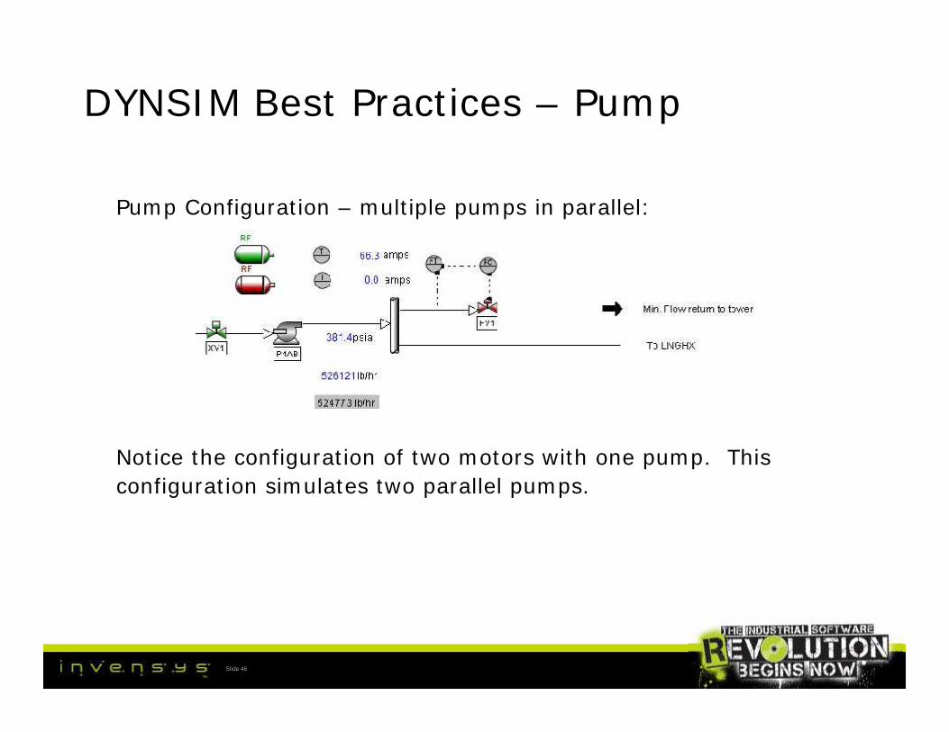
Pump Configuration – multiple pumps in parallel:
Notice the configuration of two motors with one pump. Thisconfiguration simulates two parallel pumps.
Slide 46
Pump Configuration – multiple pumps in parallel:
Notice the configuration of two motors with one pump. Thisconfiguration simulates two parallel pumps.

DYNSIM Best Practices – Pump
Pump Configuration – multiple pumps in parallel:
• Notice the QSCALE equation for parallel pumps configuration.
• This is a good illustration of simplifying simulation configurations
Slide 47
Pump Configuration – multiple pumps in parallel:
• Notice the QSCALE equation for parallel pumps configuration.
• This is a good illustration of simplifying simulation configurations
DYNSIM Demo (actual pumps in parallel)
Slide 48

DYNSIM Best Practices – Compressor
• Compressor is a flow device that is used to model a centrifugalcompressor.
• Compressor calculates the head based on the pressure differentialacross it.
• Volumetric flow rate is interpolated from the user providedperformance curves, based on the calculated head.
• Power is calculated from the user provided efficiency.
Slide 49
• Compressor is a flow device that is used to model a centrifugalcompressor.
• Compressor calculates the head based on the pressure differentialacross it.
• Volumetric flow rate is interpolated from the user providedperformance curves, based on the calculated head.
• Power is calculated from the user provided efficiency.

DYNSIM Best Practices – Compressor
• Compressor performance can be characterized by specifying threeor more points from the manufacturer provided characteristic curveor use DYNSIM® supplied default curve and specify only the designpoint.
• Flow data can be provided on volume or mass basis.
• Head data can be provided on pressure, pressure ratio, pressuredifference, or static head of the fluid being compressed.
Slide 50
• Compressor performance can be characterized by specifying threeor more points from the manufacturer provided characteristic curveor use DYNSIM® supplied default curve and specify only the designpoint.
• Flow data can be provided on volume or mass basis.
• Head data can be provided on pressure, pressure ratio, pressuredifference, or static head of the fluid being compressed.

DYNSIM Best Practices – Compressor
• Cubic spline or a linear curve fit may be chosen for the performancecurve.
• DHScale and QScale are used to scale the Compressor performance.
• Users may specify multiple performance curves for differentCompressor speeds. Alternately, fan laws can be used to scalecompressor curves with speed.
• The curve is also modified with change in inlet guide vane (IGV)position. The user also has a choice to specify performance curvesat multiple IGV positions.
Slide 51
• Cubic spline or a linear curve fit may be chosen for the performancecurve.
• DHScale and QScale are used to scale the Compressor performance.
• Users may specify multiple performance curves for differentCompressor speeds. Alternately, fan laws can be used to scalecompressor curves with speed.
• The curve is also modified with change in inlet guide vane (IGV)position. The user also has a choice to specify performance curvesat multiple IGV positions.

DYNSIM Best Practices – Compressor
• Three modes of operation:
• Normal operation where the head is positive.
• Surge operation (low flow or high head). Reverse flow may occur.Often during start-up, there is reverse flow thru a compressorsystem until there is enough inventory in the system. A compressorwill go in and out of surge.
• Stonewall (choke) operation where the compressor is operation atvery low discharge pressure and high flow rates.
Slide 52
• Three modes of operation:
• Normal operation where the head is positive.
• Surge operation (low flow or high head). Reverse flow may occur.Often during start-up, there is reverse flow thru a compressorsystem until there is enough inventory in the system. A compressorwill go in and out of surge.
• Stonewall (choke) operation where the compressor is operation atvery low discharge pressure and high flow rates.

DYNSIM Best Practices – Compressor
• Compressor calculates the shaft power, fluid flow, and fluid enthalpyrise.
• The speed is calculated externally from a Shaft or Motor and istransferred to the Compressor by a mechanical stream. Alternately,the speed may be kept constant.
• Compressor does not include either fluid or metal thermal holdup.
Slide 53
• Compressor calculates the shaft power, fluid flow, and fluid enthalpyrise.
• The speed is calculated externally from a Shaft or Motor and istransferred to the Compressor by a mechanical stream. Alternately,the speed may be kept constant.
• Compressor does not include either fluid or metal thermal holdup.

DYNSIM Demo (example compressor from Applib)
Slide 54

DYNSIM Best Practices – CompressorExample Compressor configuration with Motor, Shaft, and Mechanical
Streams:
Slide 55

DYNSIM Best Practices – CompressorCompressor – Basic Tab:
Slide 56

DYNSIM Best Practices – CompressorCompressor – Curves Tab:
Slide 57
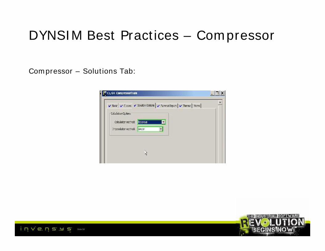
DYNSIM Best Practices – Compressor
Compressor – Solutions Tab:
Slide 58

DYNSIM Best Practices – ReciprocatingCompressor• Reciprocating Compressor is a flow device that is used to model a
reciprocating compressor or a positive displacement pump.
• The volumetric flow is calculated based on the pressure difference,shaft speed, and volumetric efficiency.
• Shaft power, fluid flow, and fluid enthalpy rise are calculated.
• Reciprocating Compressor can be loaded and unloaded where thevolumetric flow is proportional to the number of cylinders in service.The loading must be done externally (loading controls not modeled).
• Pulsation is not modeled. The reciprocating compressor does notinclude either fluid or metal thermal holdup.
Slide 59
• Reciprocating Compressor is a flow device that is used to model areciprocating compressor or a positive displacement pump.
• The volumetric flow is calculated based on the pressure difference,shaft speed, and volumetric efficiency.
• Shaft power, fluid flow, and fluid enthalpy rise are calculated.
• Reciprocating Compressor can be loaded and unloaded where thevolumetric flow is proportional to the number of cylinders in service.The loading must be done externally (loading controls not modeled).
• Pulsation is not modeled. The reciprocating compressor does notinclude either fluid or metal thermal holdup.

DYNSIM Best Practices – ReciprocatingCompressorBasic Tab:
Slide 60

DYNSIM Best Practices – ReciprocatingCompressorSolution Options Tab:
Slide 61
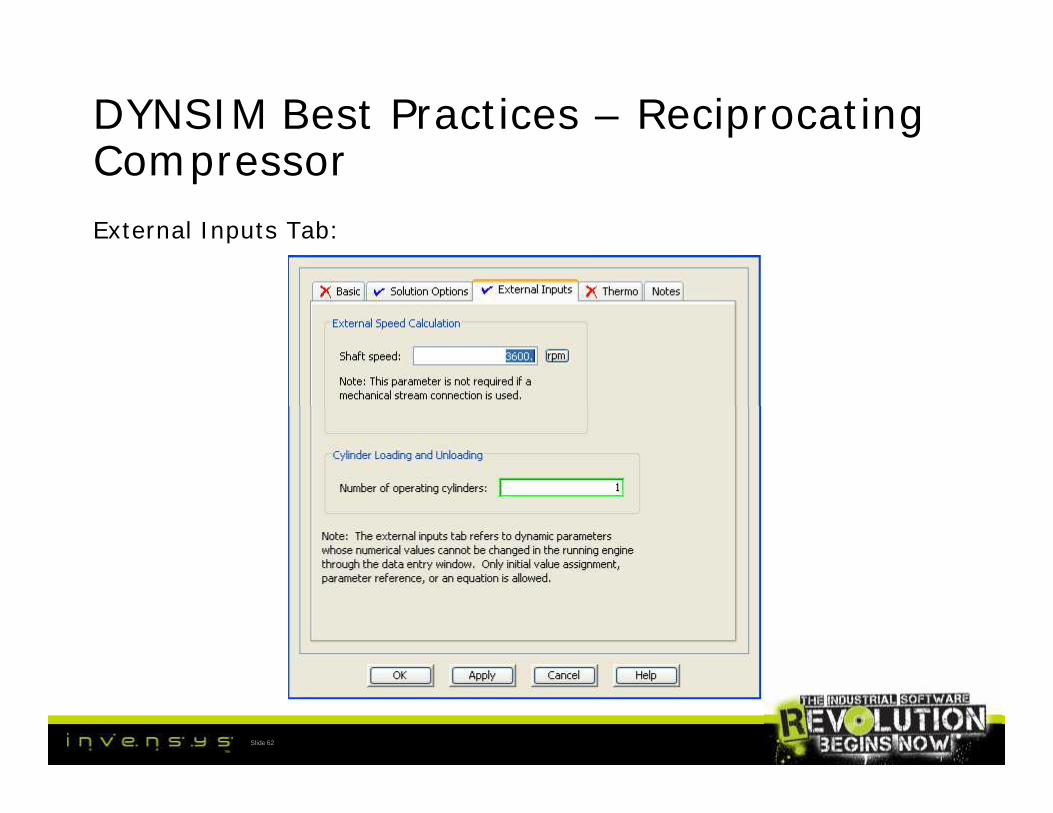
DYNSIM Best Practices – ReciprocatingCompressorExternal Inputs Tab:
Slide 62

DYNSIM Best Practices – DistillationColumn• One of the most common unit operations.
• Two objects in DYNSIM: Column (Legacy) and Tower
• Column: one pressure node at top of column; vapor holdup on toptray.
• Tower: pressure node on every tray; total holdup of vapor andliquid on every tray.
• Tower was introduced in DYNSIM 4.x. Column is retained for olderproject upgrades.
• Tower is the preferred choice for new projects.
Slide 63
• One of the most common unit operations.
• Two objects in DYNSIM: Column (Legacy) and Tower
• Column: one pressure node at top of column; vapor holdup on toptray.
• Tower: pressure node on every tray; total holdup of vapor andliquid on every tray.
• Tower was introduced in DYNSIM 4.x. Column is retained for olderproject upgrades.
• Tower is the preferred choice for new projects.
DYNSIM Best Practices – DistillationColumn• A tray represents an equilibrium stage within a tower.
• Tray numbering is from top to bottom.
• Trays can have multiple feeds and products.
• All ancillary equipment such as condensers, reboilers, accumulators,and so forth, need to be modeled separately (not like PRO/II).
• Tower accounts for heat transfer from fluids to metals and metals toits surroundings.
• Heat transfer from external sources can be input directly to themetal. Also, fluid through heat streams can be connected to theliquid holdup of any tray.
Slide 64
• A tray represents an equilibrium stage within a tower.
• Tray numbering is from top to bottom.
• Trays can have multiple feeds and products.
• All ancillary equipment such as condensers, reboilers, accumulators,and so forth, need to be modeled separately (not like PRO/II).
• Tower accounts for heat transfer from fluids to metals and metals toits surroundings.
• Heat transfer from external sources can be input directly to themetal. Also, fluid through heat streams can be connected to theliquid holdup of any tray.

DYNSIM Best Practices – DistillationColumn• Model building:
• Generally, build the tower first with constant feed, reflux, bottoms,heat duty. You get this information from your PRO/II steady stateheat and material balance.
• Tower information such as number of trays, tower dimensions, trayspacings, and so forth, can be obtained from the equipment datasheets (remember, we did our data gathering at the beginning ofthe project).
• Building the tower in this way will help achieve a steady condition inthe tower without worrying about interaction with the rest of theplant.
Slide 65
• Model building:
• Generally, build the tower first with constant feed, reflux, bottoms,heat duty. You get this information from your PRO/II steady stateheat and material balance.
• Tower information such as number of trays, tower dimensions, trayspacings, and so forth, can be obtained from the equipment datasheets (remember, we did our data gathering at the beginning ofthe project).
• Building the tower in this way will help achieve a steady condition inthe tower without worrying about interaction with the rest of theplant.

DYNSIM Best Practices – DistillationColumnModel building:
Slide 66

DYNSIM Best Practices – DistillationColumn• Some notes regarding the previous slide:
• Stream sets are OK for this initial configuration. It is better andpreferred to configure the necessary control valves and controllers.This will save rework later (eliminating the stream sets, configuringthe values, and so forth).
• Additionally, by configuring the controllers and control valves, youget a free test of the controls.
• Side note: when configuring controllers in DYNSIM, start with thedefault tunings and the Legacy control algorithm. These settings willwork in most cases.
• Just use the steady state Q for the boilup (can be added to thebottom tray, for example). This will also save reconfiguration later.
Slide 67
• Some notes regarding the previous slide:
• Stream sets are OK for this initial configuration. It is better andpreferred to configure the necessary control valves and controllers.This will save rework later (eliminating the stream sets, configuringthe values, and so forth).
• Additionally, by configuring the controllers and control valves, youget a free test of the controls.
• Side note: when configuring controllers in DYNSIM, start with thedefault tunings and the Legacy control algorithm. These settings willwork in most cases.
• Just use the steady state Q for the boilup (can be added to thebottom tray, for example). This will also save reconfiguration later.

DYNSIM Best Practices – DistillationColumnModel building continued (ovhd system not connected):
Slide 68
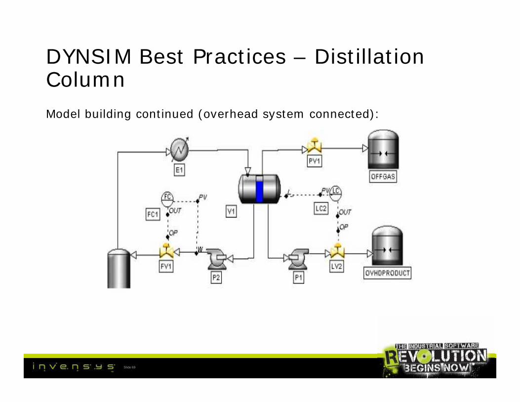
DYNSIM Best Practices – DistillationColumnModel building continued (overhead system connected):
Slide 69

DYNSIM Best Practices – DistillationColumnModel building continued (reboiler):
Slide 70

DYNSIM Best Practices – DistillationColumn• Packed tower:
• Number of equivalent trays is from design (PRO/II).
• Other parameters (in addition to the normal tower parameters suchas draw-off/pump around height, port heights, and so forth):tangent-tangent length, packing type, specific surface area, voidfraction
Slide 71
• Packed tower:
• Number of equivalent trays is from design (PRO/II).
• Other parameters (in addition to the normal tower parameters suchas draw-off/pump around height, port heights, and so forth):tangent-tangent length, packing type, specific surface area, voidfraction

DYNSIM Best Practices – DistillationColumnPacked tower:
Slide 72

DYNSIM Best Practices – DistillationColumnPacked tower:
Slide 73

DYNSIM Best Practices – DistillationColumn• Checklist (for tower modeling):
• Adjust Q’s for correct temperature profile.
• Confirm reflux is liquid and boilup is vapor.
• Check for consistency with PRO/II.
• Use the tower viewer to quickly check your tower.
Slide 74
• Checklist (for tower modeling):
• Adjust Q’s for correct temperature profile.
• Confirm reflux is liquid and boilup is vapor.
• Check for consistency with PRO/II.
• Use the tower viewer to quickly check your tower.
DYNSIM Demo (actual tower from Applib)
Slide 75

DYNSIM Best Practices – HeatExchanger• Heat Exchanger (HX) is a single pass, two-sided model that uses the
logarithmic mean temperature difference (LMTD) approach tocalculate the DUTY.
• Counter current or co-current configurations are possible.
• Both the shell side and the tube side are flow devices (conductanceneeded).
• Heat transfer is computed due to LMTD duty, natural convection,and ambient heat loss.
• Each side of the HX has a metal mass and a volume.
• Bypass flow around either side of the Heat Exchanger can bemodeled. A graphical valve is used to control the bypass flows.
Slide 76
• Heat Exchanger (HX) is a single pass, two-sided model that uses thelogarithmic mean temperature difference (LMTD) approach tocalculate the DUTY.
• Counter current or co-current configurations are possible.
• Both the shell side and the tube side are flow devices (conductanceneeded).
• Heat transfer is computed due to LMTD duty, natural convection,and ambient heat loss.
• Each side of the HX has a metal mass and a volume.
• Bypass flow around either side of the Heat Exchanger can bemodeled. A graphical valve is used to control the bypass flows.

DYNSIM Best Practices – HeatExchangerCooling water HX:
Slide 77

DYNSIM Best Practices – HeatExchanger• Cooling water HX:
• To vary cooling water flow through the exchanger, add a graphicalvalve and assign U10E4B_CW.A to the parameter Utility.Pos
• when the valve is fully open, U10E4B_CW.A = 1 and hence W =Wmax. Cooling water valves are generally full open to providemaximum cooling.
Slide 78
• Cooling water HX:
• To vary cooling water flow through the exchanger, add a graphicalvalve and assign U10E4B_CW.A to the parameter Utility.Pos
• when the valve is fully open, U10E4B_CW.A = 1 and hence W =Wmax. Cooling water valves are generally full open to providemaximum cooling.

DYNSIM Best Practices – HeatExchangerAir Cooled HX:
Slide 79

DYNSIM Best Practices – HeatExchanger
Slide 80

DYNSIM Best Practices – HeatExchanger• Air Cooled HX:
• Motors EM1 and EM2 are connected to E1 by entry in the equationslot of utility.fans
• All the motors are graphical.
• Notice the temperature control in the equation slot in theUtility.WMAX parameter. This is the technique for modelingVariable Speed Motors.
Slide 81
• Air Cooled HX:
• Motors EM1 and EM2 are connected to E1 by entry in the equationslot of utility.fans
• All the motors are graphical.
• Notice the temperature control in the equation slot in theUtility.WMAX parameter. This is the technique for modelingVariable Speed Motors.

DYNSIM Best Practices – HeatExchangerAir Cooled HX:
Slide 82

DYNSIM Best Practices – HeatExchanger• Air Cooled HX:
• Alternately, the temperature control can control louvers. The valveis graphical and is connected thru the equation slot of utility.fanssimilarly to the variable speed motors.
Utility.fans = E10_LOUVER.A * L+ (1-L)*(E10AME.SPEEDNORM +E10BME.SPEEDNORM + E10CME.SPEEDNORM +E10DME.SPEEDNORM)/4,
where L is the % the louver is open.
Slide 83
• Air Cooled HX:
• Alternately, the temperature control can control louvers. The valveis graphical and is connected thru the equation slot of utility.fanssimilarly to the variable speed motors.
Utility.fans = E10_LOUVER.A * L+ (1-L)*(E10AME.SPEEDNORM +E10BME.SPEEDNORM + E10CME.SPEEDNORM +E10DME.SPEEDNORM)/4,
where L is the % the louver is open.

DYNSIM Best Practices – HeatExchangerBasic Tab:
Slide 84

DYNSIM Best Practices – HeatExchangerHeat Transfer Tab:
Slide 85

DYNSIM Best Practices – HeatExchangerSolutions Option Tab:
Slide 86
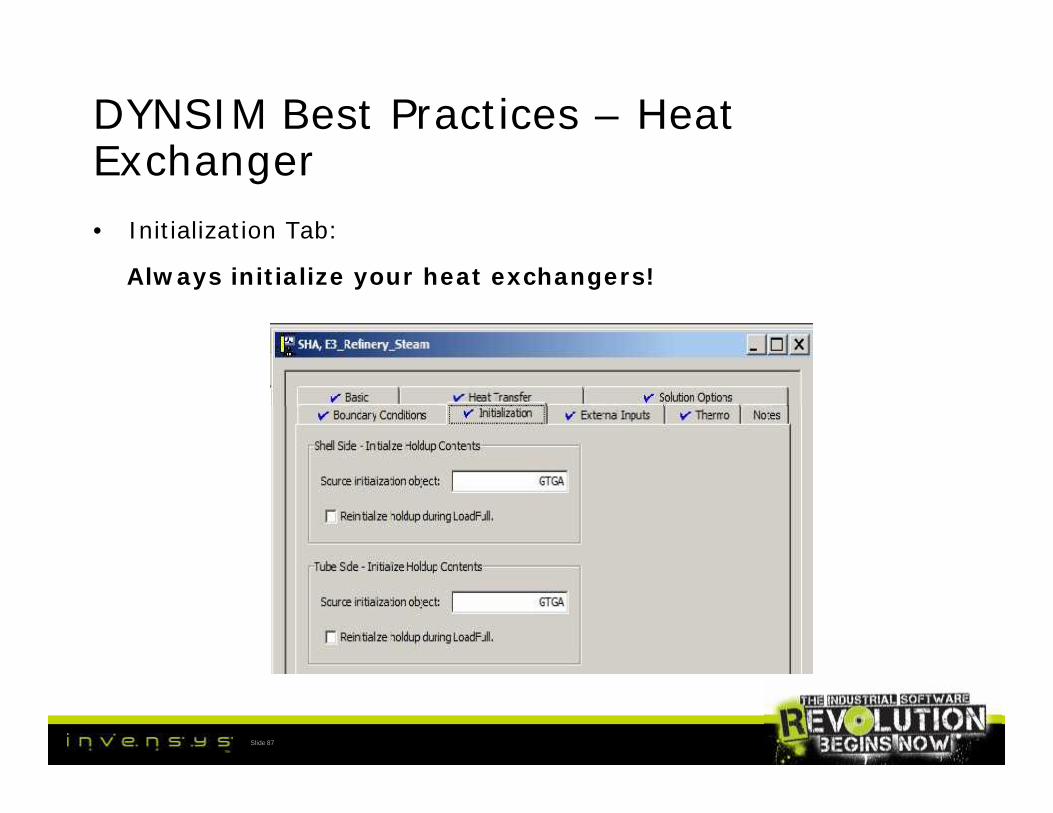
DYNSIM Best Practices – HeatExchanger• Initialization Tab:
Always initialize your heat exchangers!
Slide 87

DYNSIM Best Practices – HeatExchanger (Utility)• Basic Tab:
Other fluids can be refrigerants, for example.
Constant metal temp: no appreciable change in utility side temp.
Heat stream
Slide 88
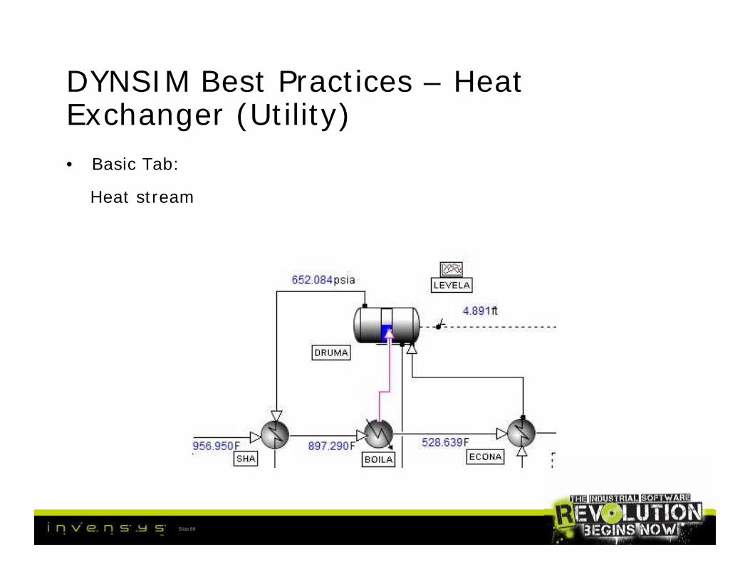
DYNSIM Best Practices – HeatExchanger (Utility)• Basic Tab:
Heat stream
Slide 89

DYNSIM Best Practices – HeatExchanger• Good to know:
• For Utility exchangers, make sure that the temperature of the utilityis defined as a global variable rather than a number entered in thefield. This will help when the temperature has to be varied as aninstructor variable.
• Flow conductance should be calculated to be in line with theallowable dP from the datasheet.
• Generally, leave natural convection and ambient HTC’s at defaultvalues to start. These coefficients can be changed during shutdownand start up testing.
Slide 90
• Good to know:
• For Utility exchangers, make sure that the temperature of the utilityis defined as a global variable rather than a number entered in thefield. This will help when the temperature has to be varied as aninstructor variable.
• Flow conductance should be calculated to be in line with theallowable dP from the datasheet.
• Generally, leave natural convection and ambient HTC’s at defaultvalues to start. These coefficients can be changed during shutdownand start up testing.

DYNSIM Best Practices – Multi PassHeat Exchanger• simulates a multi-stream heat exchanger with discrete metal nodes
between the streams.
• Used for the following applications:
• A simple pipe exchanging heat with ambient conditions
• A shell and tube heat exchanger with multiple zones
• A plate exchanger with two or more streams contacting a metalsurface
• A spiral wound LNG heat exchanger with a shell side and multipletube side passes (most common).
Slide 91
• simulates a multi-stream heat exchanger with discrete metal nodesbetween the streams.
• Used for the following applications:
• A simple pipe exchanging heat with ambient conditions
• A shell and tube heat exchanger with multiple zones
• A plate exchanger with two or more streams contacting a metalsurface
• A spiral wound LNG heat exchanger with a shell side and multipletube side passes (most common).

DYNSIM Best Practices – Multi PassHeat Exchanger
Slide 92

DYNSIM Best Practices – Multi PassHeat Exchanger
Slide 93
DYNSIM Best Practices – Multi PassHeat Exchanger• Design considerations:
• Very important to do the upfront engineering for this unit operation.It will save you rework.
• The number of units and flow passes depends on the configuration.You can see this from the previous two slides.
• Each flow pass is a flow device. A conductance needs to becalculated. Design pressure drop can be obtained from the datasheet.
Slide 94
• Design considerations:
• Very important to do the upfront engineering for this unit operation.It will save you rework.
• The number of units and flow passes depends on the configuration.You can see this from the previous two slides.
• Each flow pass is a flow device. A conductance needs to becalculated. Design pressure drop can be obtained from the datasheet.

DYNSIM Best Practices – Multi PassHeat ExchangerConfiguration:
Slide 95
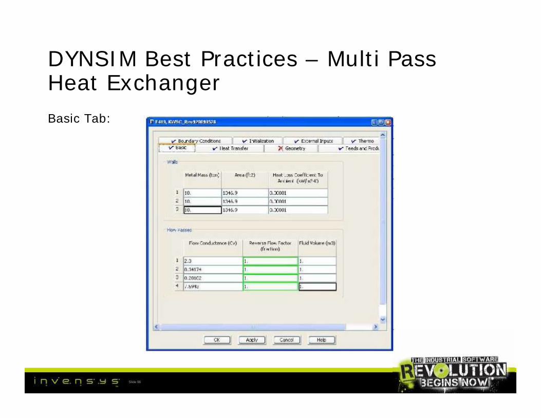
DYNSIM Best Practices – Multi PassHeat ExchangerBasic Tab:
Slide 96

DYNSIM Best Practices – Multi PassHeat ExchangerHeat Transfer Tab:
Slide 97

DYNSIM Best Practices – Multi PassHeat ExchangerGeometry Tab:
Slide 98

DYNSIM Best Practices – Multi PassHeat ExchangerFeeds and Products Tab:
Slide 99

DYNSIM Best Practices – Multi PassHeat Exchanger• Initialization Tab:
Always initialize!
Slide100

DYNSIM Demo (actual LNG HX)
Slide101

DYNSIM Best Practices – Debugging
Pressure – Flow Networks:
• The backbone of a simulation.
• Model objects are connected by streams, and all the pressure/flowrelations are solved simultaneously.
• The Simultaneous pressure flow solver views a simulation as a groupof networks. Each network includes a group of pressure nodes joinedby flow devices and surrounded by explicit pressure boundaries.
• We have already discussed the DYNSIM models that are pressurenodes (for example – Header) and flow devices (example – valve)
Slide102
Pressure – Flow Networks:
• The backbone of a simulation.
• Model objects are connected by streams, and all the pressure/flowrelations are solved simultaneously.
• The Simultaneous pressure flow solver views a simulation as a groupof networks. Each network includes a group of pressure nodes joinedby flow devices and surrounded by explicit pressure boundaries.
• We have already discussed the DYNSIM models that are pressurenodes (for example – Header) and flow devices (example – valve)

DYNSIM Best Practices – Debugging
Diagnostic Tools:
• System Health Monitor
• Network Statistics
• Flash Statistics
These tools can be used for any simulation; they are most useful forlarge simulations (OTS, for example).
Slide103
Diagnostic Tools:
• System Health Monitor
• Network Statistics
• Flash Statistics
These tools can be used for any simulation; they are most useful forlarge simulations (OTS, for example).

DYNSIM Best Practices – Debugging
System Health Monitor
Slide104

DYNSIM Best Practices – Debugging
System Health Monitor
Slide105

DYNSIM Best Practices – Debugging
Network Statistics:
Slide106
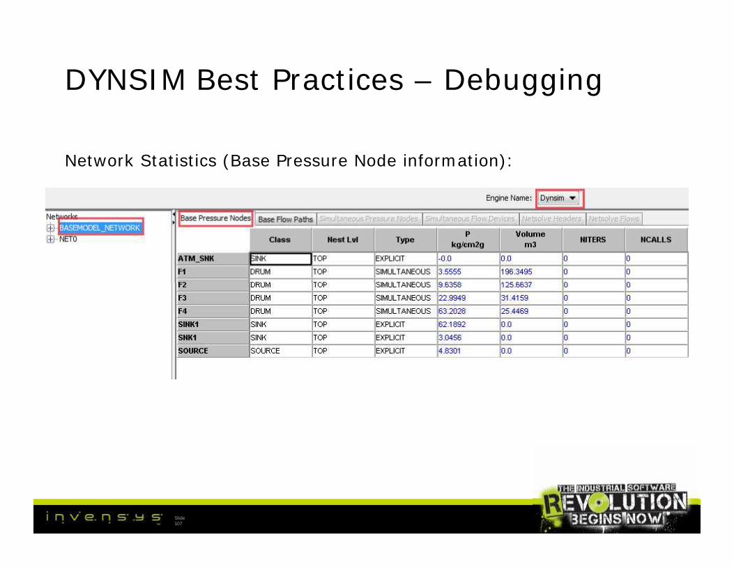
DYNSIM Best Practices – Debugging
Network Statistics (Base Pressure Node information):
Slide107

DYNSIM Best Practices – Debugging
Network Statistics (Base Flow Path information):
Slide108

DYNSIM Best Practices – Debugging
Network Statistics (Simultaneous Pressure Node information):
Slide109

DYNSIM Best Practices – Debugging
Network Statistics (Simultaneous Flow Devices information):
Slide110

DYNSIM Best Practices – Debugging
Flash Statistics:
Slide111

DYNSIM Best Practices – Debugging
Slide112

DYNSIM Best Practices – Debugging
Suggestions for solving Pressure/Flow problems:
• From network statistics, check for “red” pressure nodes. Go to thecorresponding flow sheets and check configuration. Look for highflow resistances (Cv > 1.0E5). Recalculate network resistances.More than one flow device may need recalculation.
• If recalculation is not possible, check for DP < DPLIN. If this is thecase, consider decreasing the DPLIN for the flow path only (theentire simulation DPLIN does not need to be changed).
• Check forced flow devices such as Stream Sets.
• Check for “uneven” Cvs of flow devices (example: valves in series).Consider multiplying Cv and using graphical valves.
• Demo (graphical valves)
Slide113
Suggestions for solving Pressure/Flow problems:
• From network statistics, check for “red” pressure nodes. Go to thecorresponding flow sheets and check configuration. Look for highflow resistances (Cv > 1.0E5). Recalculate network resistances.More than one flow device may need recalculation.
• If recalculation is not possible, check for DP < DPLIN. If this is thecase, consider decreasing the DPLIN for the flow path only (theentire simulation DPLIN does not need to be changed).
• Check forced flow devices such as Stream Sets.
• Check for “uneven” Cvs of flow devices (example: valves in series).Consider multiplying Cv and using graphical valves.
• Demo (graphical valves)

DYNSIM Best Practices – Debugging
Flash Statistics (previous slide):
• Look for Failures, Soft Failures, Iterations, CPU time
• Soft Failures are failure of the “simple” flash algorithm
Slide114

DYNSIM Demo (tools)
Slide115

Questions?
Slide116

Thank you!
Slide117

Slide118