pprr111133//ppdd--mm mmooddbbuussÔÔ … acronyms and definitions ... so they are all the...
TRANSCRIPT

Author Autore LB-DTA L2572 Title
Titolo PR113/PD-M Modbus System Interface ENG
���� Doc. No
N. Doc. RH0296001 Tot. Pag.
1/78 tech doc.doc
Instruction manual
PPPRRR111111333///PPPDDD---MMM MMMooodddbbbuuusss SSSyyysssttteeemmm IIInnnttteeerrrfffaaaccceee

Author Autore LB-DTA L2572 Title
Titolo PR113/PD-M Modbus System Interface ENG
���� Doc. No
N. Doc. RH0296001 Tot. Pag.
2/ 78
Index Pag.
1. GENERAL................................................................................................................................................................................. 6 1.1 APPLICABILITY .................................................................................................................................................................... 6 1.2 APPLICABLE DOCUMENTS ................................................................................................................................................... 6 1.3 ACRONYMS AND DEFINITIONS ............................................................................................................................................. 7
1.3.1 Acronyms..................................................................................................................................................................... 7 1.3.2 Definitions................................................................................................................................................................... 8
2. INTRODUCTION................................................................................................................................................................... 10 2.1 MODBUS PROTOCOL AND MAP ORGANISATION................................................................................................................. 10
2.1.1 Communication parameters ...................................................................................................................................... 10 2.1.2 Device RTU Framing ................................................................................................................................................ 10 2.1.3 Response Timeout ..................................................................................................................................................... 12 2.1.4 Reception checks ....................................................................................................................................................... 12 2.1.5 Function Codes ......................................................................................................................................................... 12 2.1.6 Data Addressing (Map organisation) ....................................................................................................................... 14 2.1.7 Data Field ................................................................................................................................................................. 16 2.1.8 Exception Responses ................................................................................................................................................. 17
2.2 INSTALLATION AND CONFIGURATION ................................................................................................................................ 18 3. START-UP BEHAVIOUR..................................................................................................................................................... 19
4. OPERATING MODE............................................................................................................................................................. 20 4.1 LOCAL OPERATING MODE ................................................................................................................................................. 20 4.2 REMOTE OPERATING MODE............................................................................................................................................... 20
5. CONFIGURATION PARAMETERS PROGRAMMING MODEL.................................................................................. 21 5.1 LOCAL PROGRAMMING STATE............................................................................................................................................ 21 5.2 REMOTE PROGRAMMING MODEL........................................................................................................................................ 22
5.2.1 Programming Model ................................................................................................................................................. 22 6. COMMANDS .......................................................................................................................................................................... 24
6.1 COMMAND CATEGORIES .................................................................................................................................................... 24 6.1.1 Wink Command......................................................................................................................................................... 24 6.1.2 Trip Reset / CB Reset ................................................................................................................................................ 25 6.1.3 Request Waveforms Start .......................................................................................................................................... 25 6.1.4 “Historical Trip Data Acquisition Start” management ............................................................................................ 27 6.1.5 Remote ‘CB Close’ command after Trip Command Fail .......................................................................................... 28
6.2 COMMANDS MANAGEMENT ............................................................................................................................................... 29 6.2.1 Commands completion .............................................................................................................................................. 29 6.2.2 CB commands execution ........................................................................................................................................... 30 6.2.3 Commands inhibition ................................................................................................................................................ 31
6.3 LOCAL COMMANDS MANAGEMENT.................................................................................................................................... 32 6.3.1 CB Open.................................................................................................................................................................... 32 6.3.2 CB Close ................................................................................................................................................................... 32 6.3.3 Trip Reset .................................................................................................................................................................. 32 6.3.4 Test Open Release (YO) ............................................................................................................................................ 32 6.3.5 Test Close Release (YC) ............................................................................................................................................ 32 6.3.6 Local programming session ...................................................................................................................................... 32
7. HUMAN-MACHINE INTERFACE / LOCAL USER INTERFACE ................................................................................ 34 7.1 LCD DISPLAY AND KEYBOARD MANAGEMENT ................................................................................................................ 34

Author Autore LB-DTA L2572 Title
Titolo PR113/PD-M Modbus System Interface ENG
���� Doc. No
N. Doc. RH0296001 Tot. Pag.
3/ 78
8. MODBUS MAP DESCRIPTION .......................................................................................................................................... 35 8.1 BUFFERS ............................................................................................................................................................................ 35
8.1.1 Reports ...................................................................................................................................................................... 36 8.1.2 Trip Reports .............................................................................................................................................................. 38 8.1.3 Statistics .................................................................................................................................................................... 38 8.1.4 Programming Fail Code ........................................................................................................................................... 39 8.1.5 Run-time Measurements............................................................................................................................................ 41 8.1.6 Trip Measurements ................................................................................................................................................... 42 8.1.7 Present Parameters (in use)...................................................................................................................................... 44 8.1.8 Waveforms Measurements ........................................................................................................................................ 45 8.1.9 Harmonics Measurements......................................................................................................................................... 45 8.1.10 Historical Trip Data.................................................................................................................................................. 46 8.1.11 Historical Measurements .......................................................................................................................................... 46 8.1.12 New Parameters........................................................................................................................................................ 49
9. MODBUS LOGICAL MAP ................................................................................................................................................... 51 9.1 DIGITAL OUTPUT ............................................................................................................................................................... 51 9.2 DIGITAL INPUT................................................................................................................................................................... 52
9.2.1 Buffer “Reports”....................................................................................................................................................... 52 9.2.2 Buffer “Trip Reports”............................................................................................................................................... 54
9.3 ANALOG INPUT .................................................................................................................................................................. 56 9.3.1 Buffer “Statistics”..................................................................................................................................................... 56 9.3.2 Buffer “Programming Fail Code”............................................................................................................................ 56 9.3.3 Buffer “Run-time Measurements” ............................................................................................................................ 57 9.3.4 Buffer “Trip Measurements” .................................................................................................................................... 59 9.3.5 Buffer “Present Parameters” ................................................................................................................................... 60 9.3.6 Buffer “Waveforms Measurements” ......................................................................................................................... 66 9.3.7 Buffer “Harmonics Measurements” ......................................................................................................................... 67 9.3.8 Buffer “Historical Trip Data” .................................................................................................................................. 67 9.3.9 Buffer “Historical Measurements”........................................................................................................................... 68
9.4 ANALOG OUTPUT............................................................................................................................................................... 69 9.4.1 Buffer “CB Open” command .................................................................................................................................... 69 9.4.2 Buffer “CB Close” command.................................................................................................................................... 69 9.4.3 Buffer “CB Reset” command .................................................................................................................................... 70 9.4.4 Buffer “Start programming session” command........................................................................................................ 70 9.4.5 Buffer “Abort programming session” command ...................................................................................................... 71 9.4.6 Buffer “Stop programming session” command ........................................................................................................ 71 9.4.7 Buffer “Trip Reset” command .................................................................................................................................. 72 9.4.8 Buffer “LC1 Open Reset” command......................................................................................................................... 72 9.4.9 Buffer “LC2 Open Reset” command......................................................................................................................... 73 9.4.10 Buffer “LC2 Number of Auto-reclosure Reset” command........................................................................................ 73 9.4.11 Buffer “Wink” command........................................................................................................................................... 74 9.4.12 Buffer “Energy Counter Reset” command................................................................................................................ 74 9.4.13 Buffer “Historical Trip Data Acquisition Start” command ...................................................................................... 75 9.4.14 Buffer “Request Waveforms Start” command........................................................................................................... 75 9.4.15 Buffer “New Parameters”......................................................................................................................................... 76

Author Autore LB-DTA L2572 Title
Titolo PR113/PD-M Modbus System Interface ENG
���� Doc. No
N. Doc. RH0296001 Tot. Pag.
4/ 78
Index of figures Pag.
FIGURE 1. CONFIGURATION PARAMETERS CATEGORIES..................................................................................................................... 21 FIGURE 2. REMOTE PROGRAMMING MODEL STATE CHART................................................................................................................ 22 FIGURE 3. WINK COMMAND BEHAVIOUR .......................................................................................................................................... 24 FIGURE 4. REQUEST WAVEFORMS START MODEL STATE CHART....................................................................................................... 26 FIGURE 5. ‘HISTORICAL TRIP DATA ACQUISITION START’ MODEL STATE CHART ............................................................................. 27 FIGURE 6. ‘COMMAND EXECUTED’ EVENT (EXECUTED BEFORE COMPLETION) ................................................................................. 30 FIGURE 7. ‘COMMAND EXECUTED’ EVENT (COMPLETED BEFORE EXECUTION) ................................................................................. 30

Author Autore LB-DTA L2572 Title
Titolo PR113/PD-M Modbus System Interface ENG
���� Doc. No
N. Doc. RH0296001 Tot. Pag.
5/ 78
Index of tables Pag.
TABLE 1. SERIAL PARAMETERS ......................................................................................................................................................... 10 TABLE 2. MODBUS MESSAGE ............................................................................................................................................................. 10 TABLE 3. RESPONSE TIMEOUT........................................................................................................................................................... 12 TABLE 4. PR113/PD-M FUNCTION CODES......................................................................................................................................... 12 TABLE 5. ‘DIAGNOSTIC’ QUERY DATA FIELD STRUCTURE.................................................................................................................. 13 TABLE 6. ‘REPORT SLAVE ID’ RESPONSE DATA FIELD STRUCTURE ................................................................................................... 13 TABLE 7. SLAVE ID ........................................................................................................................................................................... 13 TABLE 8. MODBUS LOGICAL MEMORY MAP ....................................................................................................................................... 15 TABLE 9. QUERY DATA FIELD STRUCTURE......................................................................................................................................... 16 TABLE 10. READ FUNCTION RESPONSE DATA FIELD STRUCTURE ....................................................................................................... 17 TABLE 11. MULTIPLE ITEMS WRITE FUNCTION RESPONSE DATA FIELD STRUCTURE .......................................................................... 17 TABLE 12. EXCEPTION RESPONSE ERROR CODES ............................................................................................................................... 17 TABLE 13, ADC CHANNEL FOR WAVEFORMS / HARMONICS ANALYSIS.............................................................................................. 25 TABLE 14. COMMAND RESULTS......................................................................................................................................................... 29 TABLE 15. CONDITIONS FOR COMMANDS’ INHIBITION....................................................................................................................... 31 TABLE 16. REPORTS BUFFER ............................................................................................................................................................. 36 TABLE 17. STATISTICS BUFFER ......................................................................................................................................................... 38 TABLE 18. PROGRAMMING FAIL ERROR CODE .................................................................................................................................. 41 TABLE 19. RUN-TIME MEASUREMENTS BUFFER................................................................................................................................ 41 TABLE 20. TRIP MEASUREMENTS BUFFER......................................................................................................................................... 42 TABLE 21. PRESENT PARAMETERS BUFFER ....................................................................................................................................... 45 TABLE 22. HISTORICAL TRIP DATA - BUFFER ................................................................................................................................... 46 TABLE 23. HISTORICAL TRIP DATA – RECORD.................................................................................................................................. 46 TABLE 24. HISTORICAL TRIP DATA - OPEN TYPE CODES .................................................................................................................. 46 TABLE 25. HISTORICAL MEASUREMENTS BUFFER............................................................................................................................. 46 TABLE 26. NEW PARAMETERS BUFFER ............................................................................................................................................. 50 TABLE 27. DI – BUFFER ‘REPORTS’ .................................................................................................................................................. 53 TABLE 28. DI – BUFFER ‘TRIP REPORTS’ .......................................................................................................................................... 55 TABLE 29. AI – BUFFER ‘STATISTICS’............................................................................................................................................... 56 TABLE 30. AI – BUFFER ‘PROGRAMMING FAIL CODE’ ...................................................................................................................... 57 TABLE 31. AI – BUFFER ‘RUN-TIME MEASUREMENTS’ ..................................................................................................................... 58 TABLE 32. AI – BUFFER ‘TRIP MEASUREMENTS’ .............................................................................................................................. 59 TABLE 33. AI – BUFFER ‘PRESENT PARAMETERS’, PART 1 ............................................................................................................... 60 TABLE 34. ‘CB TYPE’ RANGE ........................................................................................................................................................... 61 TABLE 35. AI – BUFFER ‘PRESENT PARAMETERS’, PART 2 ............................................................................................................... 62 TABLE 36. RELAY CONFIGURATION PARAMETERS ............................................................................................................................ 64 TABLE 37. AI – BUFFER ‘PRESENT PARAMETERS’, PART 3 ............................................................................................................... 65 TABLE 38. AI - BUFFER 'PRESENT PARAMETERS', PART 4 ................................................................................................................. 66 TABLE 39. AI - BUFFER 'WAVEFORMS MEASUREMENTS'.................................................................................................................. 66 TABLE 40. AO – BUFFER ‘CB OPEN’ COMMAND.............................................................................................................................. 69 TABLE 41. AO – BUFFER ‘CB CLOSE’ COMMAND............................................................................................................................ 69 TABLE 42. AO – BUFFER ‘CB RESET’ COMMAND ............................................................................................................................ 70 TABLE 43. AO – BUFFER ‘START PROGRAMMING SESSION’ COMMAND............................................................................................ 70 TABLE 44. AO – BUFFER ‘ABORT PROGRAMMING SESSION’ COMMAND........................................................................................... 71 TABLE 45. AO – BUFFER ‘STOP PROGRAMMING SESSION’ COMMAND.............................................................................................. 71 TABLE 46. AO – BUFFER ‘TRIP RESET’ COMMAND .......................................................................................................................... 72 TABLE 47. AO – BUFFER ‘LC1 OPEN RESET’ COMMAND................................................................................................................. 72 TABLE 48. AO – BUFFER ‘LC2 OPEN RESET’ COMMAND................................................................................................................. 73 TABLE 49. AO – BUFFER ‘LC2 NUMBER OF AUTO-RECLOSURE RESET’ COMMAND......................................................................... 73 TABLE 50. AO – BUFFER ‘WINK’ COMMAND ................................................................................................................................... 74 TABLE 51. AO – BUFFER ‘NEW PARAMETERS’, PART 1 .................................................................................................................... 76 TABLE 52. AO – BUFFER ‘NEW PARAMETERS’, PART 2 .................................................................................................................... 77 TABLE 53. AO – BUFFER ‘NEW PARAMETERS’, PART 3 .................................................................................................................... 78

Author Autore LB-DTA L2572 Title
Titolo PR113/PD-M Modbus System Interface ENG
���� Doc. No
N. Doc. RH0296001 Tot. Pag.
6/ 78
1. General This document describes the Modbus interface regarding: • Network Management of the device (installation, configuration, …) • Application Objects and Slave Variables The following are trademarks of Modicon, Inc.: Modbus 984 P190 SM85 ModConnect BM85 RR85 SQ85 Modcom BP85 SA85
1.1 Applicability This document applies to the Communication Unit of the PR113/PD-Modbus (also called PR113/PD-M) device only. It could be used as a starting point for other Modbus device too.
1.2 Applicable Documents [1] Schneider Automation Inc., ‘Modicon MODBUS Protocol Reference Guide’, June 1996, rev. J, PI-MBUS-300
http://www.modicon.com/techpubs/toc7.html

Author Autore LB-DTA L2572 Title
Titolo PR113/PD-M Modbus System Interface ENG
���� Doc. No
N. Doc. RH0296001 Tot. Pag.
7/ 78
1.3 Acronyms and Definitions
1.3.1 Acronyms ADC Analog Digital Converter AI Analog Input AO Analog Output AppObj Application Object CB Circuit Breaker (ACB EMAX family) CP Configuration Parameter CT Current Transformer CU Communication Unit (PR113/D-M) DI Digital Input DCP Dialogue (CU) Configuration Parameter DO Digital Output ETT Electronic Trip Test In Nominal current LSb Least Significant bit LSB Least Significant Byte MSb Most Significant bit MSB Most Significant Byte PCP Protection Configuration Parameter PU Protection Unit (PR113/P) OR (Main) Opening Release SOR Shunt Opening Release Tpgr Protection X Trip Time Delay (used for Protection X Zone Selectivity Time) UVR Under Voltage Release

Author Autore LB-DTA L2572 Title
Titolo PR113/PD-M Modbus System Interface ENG
���� Doc. No
N. Doc. RH0296001 Tot. Pag.
8/ 78
1.3.2 Definitions ALARM there are two types of alarm:
Alarm Type Definition
Alarm It’s similar to a status. It will be frozen after a protection trip into the “Trip Report” structures. A Trip Reset is NOT necessary to reset it. Ex. L Pre-Alarm, S Alarm, ...
Trip Only a command can reset it, i.e. a new alarm won’t be signalled until the reset. Ex. L Tripped, S Tripped, ...
Trips are reset after a Trip Reset command.
BUFFER Meaningful part of a Modbus Map section. It’s defined by the device Modbus Map.
CB RESET command equal to a Trip Reset. COIL the least digital information container (i.e. one bit) COMMUNICATION UNIT PR113/D-M electronic board that implements the Modbus interface DEVICE Protection and Communication Unit (i.e. the PR113/PD-M) EVENT information that signals a normal (foreseen) device behaviour.
Typically, the producer of an event is the device, while the consumer (who resets it) is the system. Reset of an event is automatically done after a read operation from the system.
ITEM a Digital (coil) or an Analog (register) Modbus data type OPERATION every CB status transition toward OPEN state. It doesn’t matter which is the
starting state (TRIPPED or CLOSED). OTHER TRIPS sum of CB status transitions toward the TRIPPED state, either from the
OPEN or CLOSED starting state, but not caused by the protection. So they are all the transitions caused by an electronic trip test, under voltage release and secondary shunt opening release.
PARAMETER information that allows configuration of a device functionality (e.g. a protection algorithm).
PERSISTENCE ‘volatile/non-volatile’ attribute concerning information, i.e. the information is/is not still available after a power fail/HW reset/...
PERSISTENCE Description Temporary (default)
Information is NOT still available after a power fail/HW reset/...
Permanent Information is still available after a power fail/HW reset/...
For example, parameters and trip data have this attribute set to PERMANENT, while states/events/alarms settings are TEMPORARY.

Author Autore LB-DTA L2572 Title
Titolo PR113/PD-M Modbus System Interface ENG
���� Doc. No
N. Doc. RH0296001 Tot. Pag.
9/ 78
PROTECTION TRIPS sum of real protection trips (Σ LSIG trips). ‘Real’ means ‘not caused by the Test Unit PR010/T. Trips that come up when: − Test Unit connected − CB closed and/or currents NOT equal to zero are considered ‘real’. In fact, in his case the Test Unit can only read values and can NOT simulate a trip.
PROTECTION UNIT PR113/P electronic board that implements protection algorithms PROTECTION X TRIPS sum of trip of protection X (e.g. L, S, I, G). REGISTER the least analogue information container (one word = 2 bytes) STATUS information that represents the dynamics of a functionality (e.g. the CB or a
protection algorithm). It can be managed (i.e. set/reset) only by the device itself.
TRIP COMMAND FAIL after a protection trip, with relevant opening command to the release, CB stays in CLOSED state. In this case, the CU tries to open the CB using the YO.
TRIP RESET event (Any Alarm) /alarm reset of any information related to the (last) trip. It doesn’t change the ‘real’ CB status (i.e. the CB is OPEN) but it changes the ‘virtual’ CB status from TRIPPED to OPEN.
(PROCESS) VARIABLE information strictly connected to device functionality. Examples are: − commands − states/events − alarms − measurements − historical/statistical data − ...

Author Autore LB-DTA L2572 Title
Titolo PR113/PD-M Modbus System Interface ENG
���� Doc. No
N. Doc. RH0296001 Tot. Pag.
10/ 78
2. Introduction It has been decided to describe the device according to the Modbus protocol [1] and a high level description for different functionality called Application Object (AppObj). These AOs manage the reporting of the Protection Unit information to the remote system. This information is polled by the Communication Unit to the Protection Unit according to the Internal Bus Protocol. Moreover the Communication Unit manages the Internal Bus sharing with the Test Unit (e.g. PR010/T) according to the Master Token Protocol.
2.1 Modbus Protocol and Map Organisation
2.1.1 Communication parameters 1. Transmission mode: RTU (2 four bits hexadecimal chars for each byte). 2. Serial parameters:
Start Bit Data Bits Parity Bit Stop Bit 1 8 (LSb first) 1 (even | odd) 1
Table 1. Serial parameters
Please note that mode and serial parameters MUST be the same for all devices on a Modbus network. Only the parity parameter is modifiable.
3. Baud Rate: [ 9600 | 19200 ]. DEFAULT VALUES: Even Parity, Baud Rate = 19200
2.1.2 Device RTU Framing
START SLAVE ADDRESS FUNCTION DATA CRC CHECK END T1 – T2 – T3 – T4 8 bits 8 bits n * 8 16 bits T1 – T2 – T3 – T4
Table 2. Modbus message
Up to 256 bytes can be sent. The allowed inter-character silent interval is been relaxed from ‘at least 2 characters’ to ‘at least 4 characters’ (the same silent interval to recognise the end of a message). This means:
2.1.2.1 Silent interval < 4 char between two characters inside the message In this case the receiver filters the silent interval and the following characters will be appended to those already received. The difference from the protocol specification is: 1. Silent interval < 2 char between two characters inside the message
Transmitter Receiver The behaviour is exactly as specified by the protocol.
... 4 char 4 char 1 2 n3
Silent interval
... 4 char 4 char 1 2 n3

Author Autore LB-DTA L2572 Title
Titolo PR113/PD-M Modbus System Interface ENG
���� Doc. No
N. Doc. RH0296001 Tot. Pag.
11/ 78
2. Silent interval ≥ 2 char and < 4 char between two characters inside the message The received characters are NOT flushed and the following ones will be appended. Transmitter Receiver Note that after flushing, the standard protocol specification allows: − reception of the remaining characters of a partially received message; − reception of a completely new message. The device behaviour doesn’t cover the second case because it always appends new incoming characters to the previous ones, leading to a CRC error. So the behaviour is exactly the same if and only if the incoming characters are NOT a new message. In this case the received packet will lead to a CRC error and the CRC error counter will be incremented.
2.1.2.2 Silent interval ≥≥≥≥ 4 char between two characters inside the message If the message transmission is NOT ended, all the previously received characters are managed as a message because this is exactly the protocol specification regarding the end of a message.
2.1.2.3 New frame before 4 character silent interval at the end of a frame In this case the receiver filters the silent interval and the following characters (of the new frame) will be appended to those already received (see case 2 of par. 2.1.2.1). This will lead to a CRC error.
Transmitter Receiver
So the CRC error counter will count both the ‘real’ CRC errors and the inter-character errors.
... 4 char 4 char 1 2 n3
Silent interval
... 4 char 1 2 n3
Silent interval
4 char
Silent interval
... 4 char 1 2 n3 ... 4 char 1 2 m3
... 4 char 1 2 n3 ... 4 char 1 2 m3

Author Autore LB-DTA L2572 Title
Titolo PR113/PD-M Modbus System Interface ENG
���� Doc. No
N. Doc. RH0296001 Tot. Pag.
12/ 78
2.1.3 Response Timeout The reported timeouts have been measured over more than 100 samples (normal responses) in the following conditions: • device in ‘normal’ status, i.e. only measurements are periodically updated and NO alarm conditions are satisfied
Minimum (ms) Medium (ms) Maximum (ms) Single COIL Read 18.35 19 20.99 Multiple COILS (69) Read 23.6 25 26.2 Single REGISTER Read 18.35 18.8 21.4 Multiple REGISTERS (98) Read 130 131.2 134.87
Table 3. Response Timeout
Please note that the multiple items read has been performed on maximum number of items allowed by the device map, in particular: • 69, status / events, alarms, trips • 98, present parameters in use The minimum suggested response timeout for periodically polled information is 25 ms.
2.1.4 Reception checks After reception, the device performs the following checks: • CRC, • Max Message Length allowed (256 bytes), • Slave Address. If any of this information is not correct, the received message is discarded and no response message is sent back to the Master.
2.1.5 Function Codes The following standard functions have to be supported:
Code HEX Code Name Applies to 01 0x01 Read Coil Status DO 02 0x02 Read Input Status DI 03 0x03 Read Holding Register AO 04 0x04 Read Input Register AI 05 0x05 Force Single Coil DO 06 0x06 Preset Single Register AO 08 0x08 Diagnostic
Sub-function: 0 (0x00)
15 0x0F Force Multiple Coils DO 16 0x10 Preset Multiple Registers AO 17 0x11 Report Slave ID
Table 4. PR113/PD-M function codes
All other NOT supported function codes lead to an Exception response ‘ILLEGAL_FUNCTION’.

Author Autore LB-DTA L2572 Title
Titolo PR113/PD-M Modbus System Interface ENG
���� Doc. No
N. Doc. RH0296001 Tot. Pag.
13/ 78
These functions can be grouped into two different categories: 1. Data Management functions.
Functions applied to device data into the Modbus Map (codes 01, 02, 03, 04, 05, 06, 15 and 16).
2. Network / Device Management functions. Functions applied to device that can: • request / setting general information • change the device behaviour / status • … Function code 08 and 17 belong to this category.
2.1.5.1 08 (0x08) Diagnostic The function uses a two-byte sub-function code field in the query to define the type of test to be performed. Most of the diagnostic queries use a two-byte data field to send diagnostic data or control information to the slave.
Sub-function Hi Sub-function Lo Data Hi Data Lo
Table 5. ‘Diagnostic’ query data field structure
where the only supported sub-function code is:
Sub-function code HEX code Name Description 00 0x00 Return Query Data The data passed in the information field will be returned
to the Master via the addressed Modbus Slave. The entire message returned should be identical to the message transmitted by the Master, field-per-field.
NOTE: the protocol specification on data field (‘Any’, pages 74 – 75, 77) is NOT clear. The device allows both a generic field length (i.e. more than two bytes) and a generic value range.
2.1.5.2 17 (0x11) Report Slave ID A normal response has some fields defined and others device dependent:
Byte Count Slave ID Run Indicator Status Additional Data ...
Table 6. ‘Report Slave ID’ response data field structure
where: • ‘Byte Count’ depends on ‘Additional Data’. Its minimum value is 2. • ‘Slave ID’ is the identifier of the device of a specific manufacturer (i.e. devices from different manufacturers could have the
same ‘Slave ID’):
Slave ID Device 12 = 0x0C PR113/PD-M
Table 7. Slave ID
• ‘Run Indicator Status’ reports the current Slave Run status, fixed to ON (0xFF).

Author Autore LB-DTA L2572 Title
Titolo PR113/PD-M Modbus System Interface ENG
���� Doc. No
N. Doc. RH0296001 Tot. Pag.
14/ 78
2.1.6 Data Addressing (Map organisation) Two different data addressing types are implemented: 1. Standard Modbus addressing 2. ABB SACE addressing (old ABB SACE Modbus Communication Units)
Standard ABB Starting Address
Item Address
Data Type Starting Address
Item Address
0 … 9999
1 … 10000
DO 1 … 10000
1 … 10000
0 … 9999
10001 … 20000
DI 10001 … 20000
10001 … 20000
0 … 9999
30001 … 40000
AI 30001 … 40000
30001 … 40000
0 … 9999
40001 … 50000
AO 40001 … 50000
40001 … 50000
It is possible to configure it using the ‘Network Info’ menu of the HMI. The organisation of every section of the map (i.e. DO, DI, AI, AO) can be partitioned into different areas, called ‘buffers’, containing a contiguous number of item. For example
Item Address Item Value 1 … 27 28 29 30 31 … … 10000
defines a DO buffer starting at 27 and with length 5 (grey cells are map items not defined for the device).

Author Autore LB-DTA L2572 Title
Titolo PR113/PD-M Modbus System Interface ENG
���� Doc. No
N. Doc. RH0296001 Tot. Pag.
15/ 78
Please note that:
Item Address Item Value 1 … 27 28 29 30 31 32 … 10000
defines two different DO buffers. The first one starts at 27 with length 2, while the second one starts at 30 with length 3. It’s possible to query a buffer as a whole or a portion of it, but it’s NOT possible to query two buffers within the same message: an exception response will rise up.
2.1.6.1 Standard Modbus Addressing In Modbus messages Start Address is always referred to zero. Every single item in these sections is identified by a LOGICAL ABSOLUTE ADDRESS in the following ranges:
Data Logical Absolute Address Range Offset / Reference (decimal) Offset / Reference (hex) DO 00001 – 10000 (MAX_DO_ADDR) 00000 (DO_OFFSET) 0x0000 DI 10001 – 20000 (MAX_DI_ADDR) 10000 (DI_OFFSET) 0x2710 AI (MIN_AI_ADDR) 30001 – 40000 (MAX_AI_ADDR) 30000 (AI_OFFSET) 0x7530 AO 40001 – 50000 (MAX_AO_ADDR) 40000 (AO_OFFSET) 0x9C40
Table 8. Modbus logical memory map
Please note that when the Master specifies the ‘Starting Address’ into the Modbus message, it uses a LOGICAL RELATIVE ADDRESS, calculated from the LOGICAL ABSOLUTE ADDRESS:
Starting Address = LOGICAL RELATIVE ADDRESS = LOGICAL ABSOLUTE ADDRESS – XX_OFFSET –1 = Item Address – XX_OFFSET –1
Equation 1. So the Logical Relative Address Range is 00000 – 09999 (= 0x270F, MAX_RELATIVE_ADDR) for all data types. Moreover, items like 10005, 40001, ... are addressed like 0005, 0001, ... because the function code uniquely identifies the portion of Modbus map they belong to. Example Coil with LOGICAL ABSOLUTE ADDRESS = 13 will be addressed by the Master with the LOGICAL RELATIVE ADDRESS = 12. Register with LOGICAL ABSOLUTE ADDRESS = 32475 will be addressed by the Master with the LOGICAL RELATIVE ADDRESS = 32475 – 30000 – 1 = 2474.

Author Autore LB-DTA L2572 Title
Titolo PR113/PD-M Modbus System Interface ENG
���� Doc. No
N. Doc. RH0296001 Tot. Pag.
16/ 78
So the device performs the following check on the Starting Address field: • Starting Address range between 0 and 9999 • Starting Address belongs to a valid part of the section pointed by the Function Code
2.1.6.2 ABB SACE Addressing The item address is:
Starting Address = LOGICAL ABSOLUTE ADDRESS = Item Address The device performs the following check on the Starting Address field: • Starting Address congruency with the section pointed by the Function Code (see Table 8). • Starting Address belongs to a valid part of the pointed section
2.1.7 Data Field The data field is formed by an ‘header’ part and a data value part: following points consider only the header part of this field. In some function, there could be a 0 length data field (i.e. the message contains only the function code like in the ‘Report Slave ID’ function). There is no restriction to max data length except the maximum message length (256 bytes).
2.1.7.1 Query
Number of items [2 bytes] (except writing functions 5 and 6)
Byte Count (only for writing functions 15 and 16) [1 byte]
How many items to read/write How many data bytes follow
Table 9. Query data field structure
Function Code Data Type Max number of items Max byte count Min message length Max message length
1 DO 2008 (251 * 8) N/A 8 8 2 DI 2008 (251 * 8) N/A 8 8 3 AO 125 N/A 8 8 4 AI 125 N/A 8 8 5 DO N/A (1 fixed) N/A 8 8 6 AO N/A (1 fixed) N/A 8 8 15 DO 1976 (247 * 8) 247 10 256 16 AO 123 246 11 256
The device performs the following checks on the above-mentioned fields: • Max number of items, conforming to the Function Code • Byte Count congruency with the Number of Items • Data value field length congruency with the Byte Count Moreover, also the following checks are performed: • (Starting Address + Number Of Items) belongs to the section pointed by the Function Code • (Starting Address + Number Of Items) belongs to a valid part of the pointed section
2.1.7.2 Response 1. Read function codes

Author Autore LB-DTA L2572 Title
Titolo PR113/PD-M Modbus System Interface ENG
���� Doc. No
N. Doc. RH0296001 Tot. Pag.
17/ 78
Byte Count (only for writing functions 15 and 16) [1 byte] How many data bytes follow
Table 10. Read function response data field structure
Function Code Data Type Max number of items Max byte count Min message length
1 DO 2008 (251 * 8) 251 6 2 DI 2008 (251 * 8) 251 6 3 AO 125 250 7 4 AI 125 250 7
2. Single item Write function codes (5, 6)
It’ simply an echo of the query message. 3. Multiple items Write function codes (15, 16)
Starting Address [2 bytes] Number of items [2 bytes]
Starting item How many items to read/write
Table 11. Multiple items Write function response data field structure
So the message length is fixed and equal to 8.
2.1.8 Exception Responses In this case, the MSb of the function code in the response message is set to one and an error code is added.
Error Code Error Name Meaning 01 ILLEGAL FUNCTION The function code received in the query is not an allowable action for the
slave. If a ‘Poll Program Complete’ command is issued, this code indicates that no program function preceded it.
02 ILLEGAL DATA ADDRESS The data address received in the query is not an allowable address for the slave.
03 ILLEGAL DATA VALUE A value contained in the query data field in not an allowable value for the slave.
06 SLAVE DEVICE BUSY The slave is processing a long-duration program command. The master should retransmit the message later when the slave is free.
Table 12. Exception response error codes
No response is sent by the slave device if there is a communication error (i.e. a parity o a CRC error).

Author Autore LB-DTA L2572 Title
Titolo PR113/PD-M Modbus System Interface ENG
���� Doc. No
N. Doc. RH0296001 Tot. Pag.
18/ 78
Error Code Error Name When
01 ILLEGAL FUNCTION 1. The message is too short (i.e. there is NO Function Code field!), with right CRC.
2. Device does NOT support the received Function Code. Please note that this means that the Function Code 2 (Read Input Status, DI) will NOT lead to this Exception.
02 ILLEGAL DATA ADDRESS 1. The message is too short (i.e. there is NO Starting Address field!), with
right CRC. 2. Starting Address is > 10000 (Standard Addressing Type). 3. Starting Address is outside a map section (ABB SACE Addressing
Type). 4. Starting Address doesn’t belong to any buffer.
03 ILLEGAL DATA VALUE 1. The message is too short, with right CRC. 2. The message is too long, with right CRC. 3. Diagnostic function: sub-function is not supported (� 0) 4. The Number of Items is NOT in range (= 0 or > Max number of items,
see 2.1.7). 5. Byte Count is different from the number of bytes calculated using the
number of items and the relevant data type. 6. The whole query requested buffer (Starting Address + Number of Items)
doesn’t belong to a device map buffer. 7. Force Single Coil function: the value is different from 0x0000 or
0xFF00. 8. Command value: it is different from ‘1’. 9. DCP Installation Date value: not valid
06 SLAVE DEVICE BUSY 1. Start-up (before complete polling of PU information) 2. Commands inhibition (see par. 6.2.3)
2.2 Installation and Configuration At the first start-up, the device is NOT configured for communication to the remote system. The communication parameters to be defined are:
Communication Parameters Allowed Values Start Up Values Slave Address {1 … 247} | 255 (UNCONFIGURED) 255 (UNCONFIGURED) Baud Rate 9600 | 19200 bit/s 19200 bit/s Parity Even | Odd Even Addressing Type Standard | ABB SACE Standard
These parameters can be changed if and only if the Operating Mode is LOCAL, using the LCD Display of the device. If the device is NOT configured (i.e. Slave Address = 255), no query is processed and the warning message ‘MODBUS Not Configured’ is displayed in the first line of the LCD Display.

Author Autore LB-DTA L2572 Title
Titolo PR113/PD-M Modbus System Interface ENG
���� Doc. No
N. Doc. RH0296001 Tot. Pag.
19/ 78
3. Start-up behaviour At start up, the Communication Unit needs about 5 seconds to update the information coming from the Protection Unit. During this time, the data are not available to the remote system: the Communication Unit returns a “SLAVE DEVICE BUSY” exception response to any query coming from it. If an “Internal Bus Fault” condition occurs during the Start-up, preventing from information update, the CU sets all the information to default values, letting the remote system to read the data:
Data Type Default Values Description States/Events/Alarms/Trips (but IB Status)
0 No alarm pending: the only one set is “IB Fault”
IB Status 1 This value are readable only when a “IB fault” condition occurs at start up
CB States Value read from I/O They don’t depend on Internal Bus communication Parameters 0xFF Values out of allowed ranges Measurements 0xFF Values out of allowed ranges � Not reliable data Communication Statistics 0 They are updated run-time PU Process Statistics 0xFF Data not available CU Process Statistics Value read from EEPROM They don’t depend on Internal Bus communication

Author Autore LB-DTA L2572 Title
Titolo PR113/PD-M Modbus System Interface ENG
���� Doc. No
N. Doc. RH0296001 Tot. Pag.
20/ 78
4. Operating Mode The device can operate in two different modes, Local and Remote. The mode can be selected by means of a dedicated menu of the device (PU). The default value at start up is “Local”.
4.1 Local Operating Mode From the remote point of view, the device has the following behaviour:
Actions forbidden Actions allowed No remote parameterisation allowed Consultation of measurements No remote command allowed Consultation of configuration parameters of the device Consultation of protection unit information
4.2 Remote Operating Mode From the remote point of view, the device has the following behaviour:
Actions forbidden Actions allowed Remote parameterisation allowed Remote command allowed Consultation of measurements Consultation of configuration parameters of the device Circuit Breaker commands (open / close)
None
Trip Reset / CB Reset

Author Autore LB-DTA L2572 Title
Titolo PR113/PD-M Modbus System Interface ENG
���� Doc. No
N. Doc. RH0296001 Tot. Pag.
21/ 78
5. Configuration parameters programming model
Figure 1. Configuration parameters categories
5.1 Local programming state Every time the PU stores a new parameter configuration, the CU updates it and if something has changed, propagates towards the remote system the event “Parameters changed”. PR113 is considered to be in “Local Programming” state when at least one of the following situations is verified: 1. PR113/PD Operating Mode = LOCAL
2. Test Unit Connected
When the Test Unit disconnection occurs, the CU reads the configuration parameters to update them towards the remote system.
PCP
DCP
Configuration Parameters
Locally modifiable
Remotely modifiable Locally modifiable Remotely modifiable

Author Autore LB-DTA L2572 Title
Titolo PR113/PD-M Modbus System Interface ENG
���� Doc. No
N. Doc. RH0296001 Tot. Pag.
22/ 78
5.2 Remote programming model It is possible to configure two different kinds of configuration parameters: a) Protection Configuration Parameters (PCP) relevant to the PU b) Dialogue Configuration Parameters (DCP) relevant to the CU All these configuration parameters are readable, while only some of them are remotely modifiable. All configuration parameters are Items. They can be: • READ ONLY (the system can’t modify them)
The configuration parameter is associated only to an Input Item (DI / AI) • READ/WRITE (the system can modify them)
The configuration parameter is associated both to an Input (DI / AI) and to an Output (DO / AO) Item Obviously, “READ/WRITE” configuration parameters are a subset of those “READ ONLY”.
5.2.1 Programming Model
Figure 2. Remote Programming Model state chart STATE NAME STATE DESCRIPTION PROGRAMMING OK Item PROGRAMMING FAIL Item
INIT Initial state 0 0 IDLE / SESSION END Session is ended 0 0 SESSION ON Session is active 1 1 PROGRAMMING OK Session ended without errors 1 0 PROGRAMMING FAIL Session ended with errors 0 1
IDLE / SESSIONEND
SESSION ON
PROGRAMMINGOK
PROGRAMMINGFAIL
INIT
1
5
4
7
10
8
6
9
32

Author Autore LB-DTA L2572 Title
Titolo PR113/PD-M Modbus System Interface ENG
���� Doc. No
N. Doc. RH0296001 Tot. Pag.
23/ 78
TRANSITION INITIAL STATE FINAL STATE TRANSITION CONDITION 1 INIT IDLE / SESSION END Start-up 2 IDLE / SESSION END SESSION ON ‘Start programming’ command received from system. 3 SESSION ON IDLE / SESSION END ‘Abort programming’ command received from system. 4 SESSION ON SESSION ON ‘Start programming’ command received from system. 5 SESSION ON IDLE / SESSION END Session timeout (1 hour) 6 SESSION ON PROGRAMMING FAIL ‘Stop programming’ command received from system and
errors detected (see also ‘Programming Fail Code’). 7 PROGRAMMING FAIL SESSION ON ‘Start programming’ command received from system. 8 SESSION ON PROGRAMMING FAIL A ‘local’ aborting event has occurred:
1. Internal Bus Fault 2. Operating Mode from REMOTE to LOCAL
9 SESSION ON PROGRAMMING OK ‘Stop programming’ command received from system and NO errors detected.
10 PROGRAMMING OK SESSION ON ‘Start programming’ command received from system. The actions associated to each transition are:
TRANSITION ACTION 1 N/A 2 1. Set the programming items.
2. Copy the ‘Present parameters’ buffer into ‘New Parameters’. 3 Reset the programming items. 4 Copy the ‘Present parameters’ buffer into ‘New Parameters’. 5 Reset the programming items. 6 1. If needed, PU programming.
2. If there is NO error and it’s needed, CU programming. 3. If there is an error, reset the ‘Programming OK’ item and
write the ‘Programming Fail Code’ item. 7 1. Set the ‘Programming OK’ item.
2. Copy the ‘Present parameters’ buffer into ‘New Parameters’. 8 Reset the ‘Programming OK’ item. 9 1. If needed, PU programming.
2. If there is NO error and it’s needed, CU programming. 3. If there is NO error, reset the ‘Programming Fail’ item and
set the ‘Parameter Changed’ item 10 1. Set the ‘Programming Fail’ item.
2. Copy the ‘Present parameters’ buffer into ‘New Parameters’. NOTE: When the CU is in SESSION ON state, the Internal Bus is NOT shared with the Test Unit, i.e. the Master Token is not released from the CU to the Test Unit.

Author Autore LB-DTA L2572 Title
Titolo PR113/PD-M Modbus System Interface ENG
���� Doc. No
N. Doc. RH0296001 Tot. Pag.
24/ 78
6. Commands The CU manages two different command ‘sources’: 1. Remote Operator Station, i.e. a remote command from the system (remote command) 2. Local Operator, i.e. an action performed locally on the relay and / or the circuit breaker (local command) From now on, the word ‘command’ means ‘remote command’.
6.1 Command Categories Remote commands handled by CU can be organised in three different categories: a) Protection Unit Slow Commands: they are the commands requiring a significant amount of time for being executed due to an
‘heavy’ interaction with the PU • Start Programming • Stop Programming • Request Waveforms Start • Historical Trip Data Acquisition Start
b) Protection Unit Fast Commands: they are the commands requiring a negligible amount of time for being executed, even if there is an interaction with the PU • Abort Programming • Wink • Trip Reset / CB Reset • LC1 Open Reset • LC2 Open Reset • LC2 Number of AR Reset • Energy Counter Reset
c) Circuit Breaker Commands: they are commands concerning only the Circuit Breaker • CB Open • CB Close • CB Reset
Only the value ‘1’ is allowed for a command. If a different value is sent, an exception response ‘ILLEGAL_DATA_VALUE’ will be returned. The commands concerning only the PU (e.g. Trip Reset) and not the Circuit Breaker are independent from CB states.
6.1.1 Wink Command The “wink” command is used for recognising a device by making its display flash (also a warning message is displayed). The command is sent from the remote system and has a toggle behaviour, i.e., to stop the LCD display flashing another “wink” command has to be sent. See the following finite state machine:
Figure 3. Wink Command behaviour
LCD Flashing
LCD Not Flashing
Wink command
Wink command

Author Autore LB-DTA L2572 Title
Titolo PR113/PD-M Modbus System Interface ENG
���� Doc. No
N. Doc. RH0296001 Tot. Pag.
25/ 78
6.1.2 Trip Reset / CB Reset These commands are equivalent. In fact, both reset: 1. the internal CU states 2. the relevant PU states and magnetic flag 3. the external signalling unit (e.g. PR010/K) This is also the behaviour of the CU when a LOCAL Trip Reset command is issued by pressing the frontal ‘RESET’ push button.
6.1.3 Request Waveforms Start This command allows the acquisition of waveforms and harmonics. To be properly managed, the command requires two information that are set through the following parameters: • ADC channel to be analyzed: this parameter selects the channel (and consequently the measurement) to be analysed to acquire
the waveforms. The allowed values are:
Channel Description 0 No channel selected (default) 1 Current phase L1 2 Current phase 2 3 Current phase 3 4 Neutral Current 5 Voltage phase 1 6 Voltage phase 2 7 Voltage phase 3 8 Ground Current
Table 13, ADC channel for waveforms / harmonics analysis
If no channel is selected, the command can’t be executed and an exception response ‘SLAVE_DEVICE_BUSY’ is returned. • Harmonics request: this parameter allows to enable the acquisition of harmonics
0 Harmonics acquisition disable (default) 1 Harmonics acquisition enable
If not set, its value is zero (harmonics not requested).
6.1.3.1 Waveforms/Harmonics value transformation The Communication Unit acquires these data in a raw format (Protection Unit format). The transformation in engineering format is due to the remote system. The transformation algorithms are: 1. Waveforms - Current Channel
[ ]181
* InsampleAOutput =
Equation 2. Waveforms transformation functions - Current channel
where: Output [A] transformed value expressed in ampere sample value read from Protection Unit In Nominal Current

Author Autore LB-DTA L2572 Title
Titolo PR113/PD-M Modbus System Interface ENG
���� Doc. No
N. Doc. RH0296001 Tot. Pag.
26/ 78
2. Waveforms - Voltage Channel
[ ]1200
*UnsampleVOutput =
Equation 3. Waveform transformation function - Voltage channel
where: Output [V] transformed value expressed in volt sample value read from Protection Unit Un Nominal Voltage 3. Harmonics
[ ]10
%sample
Output =
Equation 4. Harmonics transformation function
where: Output [%] transformed value expressed in percentage of fundamental frequency sample value read from Protection Unit NOTE: if the net frequency is 60 Hz, the 20th harmonic is not available and the Protection Unit returns 0xFFFF.
6.1.3.2 ‘Request Waveforms Start’ command model The proper procedure to acquire the waveforms and the harmonics (if requested) is: a) Select the channel to analyze (1 to 8) b) Select the request of harmonics (enable = 1 / disable = 0) c) Send the command
AcquisitionON
AcquisitionOK
AcquisitionFail
1
2
3
6 6
4 5
INIT
ParameterSelection
Figure 4. Request Waveforms Start Model state chart

Author Autore LB-DTA L2572 Title
Titolo PR113/PD-M Modbus System Interface ENG
���� Doc. No
N. Doc. RH0296001 Tot. Pag.
27/ 78
STATE NAME STATE DESCRIPTION ACQUISITION OK Item ACQUISITION FAIL Item
INIT Initial state 0 0 PARAMETERS SELECTION Choose channel and waveforms 0 0 ACQUISITION ON Begin acquisition 1 1 ACQUISITION OK Acquisition ended without errors 1 0 ACQUISITION FAIL Acquisition ended with errors 0 1
TRANSITION INITIAL STATE FINAL STATE TRANSITION CONDITION 1 INIT PARAMETERS SELECTION Start-up 2 PARAMETERS SELECTION PARAMETERS SELECTION Wait for correct selection of parameters 3 PARAMETERS SELECTION ACQUISITION ON Command received from remote system 4 ACQUISITION ON ACQUISITION OK Acquisition ended without errors 5 ACQUISITION ON ACQUISITION FAIL Acquisition ended with errors 6 ACQUISITION OK / ACQUISITION FAIL PARAMETERS SELECTION New parameters selection occurs
TRANSITION ACTION 1 N.A. 2 1. Set parameters (channel and harmonics request)
1.1. If channel invalid � SLAVE DEVICE BUSY 3 Set acquisition items 4 Reset ‘Acquisition Fail’ item 5 Reset ‘Acquisition OK’ item 6 N.A.
6.1.4 “Historical Trip Data Acquisition Start” management This command allows the acquisition of the last ten trip events recorded by Protection Unit. The Communication Unit provides them in a temporal order, from oldest to newest.
6.1.4.1 ‘Historical Trip Data Acquisition Start’ command model The proper procedure to acquire the trip data is:
1
2
3 4
5 5
Idle
INIT
AcquisitionON
AcquisitionOK
AcquisitionFAIL
Figure 5. ‘Historical Trip Data Acquisition Start’ Model state chart

Author Autore LB-DTA L2572 Title
Titolo PR113/PD-M Modbus System Interface ENG
���� Doc. No
N. Doc. RH0296001 Tot. Pag.
28/ 78
STATE NAME STATE DESCRIPTION ACQUISITION OK Item ACQUISITION FAIL Item TRIP DATA AVAILABLE item
INIT Initial state 0 0 1 ACQUISITION ON Begin acquisition 1 1 0 ACQUISITION OK Acquisition ended without errors 1 0 1 ACQUISITION FAIL Acquisition ended with errors 0 1 1
TRANSITION INITIAL STATE FINAL STATE TRANSITION CONDITION 1 INIT IDLE Start-up 2 IDLE ACQUISITION ON Command received from remote system 3 ACQUISITION ON ACQUISITION OK Acquisition ended without errors 4 ACQUISITION ON ACQUISITION FAIL Acquisition ended with errors 5 ACQUISITION OK / ACQUISITION FAIL IDLE Session ended
TRANSITION ACTION 1 N.A. 2 1. Reset ‘Trip Data Available’ item
2. Set acquisition items 3 Reset ‘Acquisition Fail’ item 4 Reset ‘Acquisition OK’ item 5 N.A.
6.1.5 Remote ‘CB Close’ command after Trip Command Fail When a “Trip Command Fail” condition occurs (see its definition in par. 1.3.2), the CB reaches the “Open” position: in this situation the only allowed remote command is “Trip Reset”. Only after it, the “Close” command is accepted.

Author Autore LB-DTA L2572 Title
Titolo PR113/PD-M Modbus System Interface ENG
���� Doc. No
N. Doc. RH0296001 Tot. Pag.
29/ 78
6.2 Commands management
6.2.1 Commands completion After receiving a command, the CU verifies the inhibition conditions and sends the response. If there is an error, an exception response is sent and the requested command is NOT processed. Even if there is an error or not, during this time, the relevant command item is NOT reset, signalling that the command is pending, and command completion will be signalled by the relevant item reset. If there is NO error, the command result is signalled in the following way:
Command result Start Programming Programming OK = Programming Fail = 1 (i.e. Remote programming session ON)
Abort Programming Programming OK = Programming Fail = 0 (i.e. Remote programming session OFF) Stop Programming 1. Programming result = OK
• Programming OK = 1, Programming Fail = 0 • Parameter changed = 1
2. Programming result = FAIL • Programming OK = 0, Programming Fail = 1
3. Nothing changed • Programming OK = Programming Fail = 0
Wink 1. LCD Display flashing ON / OFF 2. Warning message on the first line of the LCD Display
CB Reset 1. CB Tripped reset, if previously set (mutually exclusive with Trip Command Fail Item) 2. Trip Command Fail reset, if previously set (mutually exclusive with CB Tripped Item) 3. Relevant Trip Item reset � Any Trip reset 4. Magnetic flags reset 5. Signalling Unit reset, if present
Trip Reset 1. CB Tripped reset, if previously set (mutually exclusive with Trip Command Fail Item) 2. Trip Command Fail reset, if previously set (mutually exclusive with CB Tripped Item) 3. Relevant Trip Item reset � Any Trip reset 4. Magnetic flags reset 5. Signalling Unit reset, if present
CB Open CB Open / Closed = 0, if CB Undefined = 0 CB Close CB Open / Closed = 1, if CB Undefined = 0
LC1 Open Reset Relevant Alarm Item reset � Any Alarm reset, if no more alarms are set LC2 Open Reset Relevant Alarm Item reset � Any Alarm reset, if no more alarms are set
LC2 Nr. AR Reset 1. Relevant Alarm Item reset � Any Alarm reset, if no more alarms are set 2. Number of auto-reclosure = 0
Energy Counter Reset 1. Energy measurements set to zero Request Waveforms
Start 1. Acquisition result = OK
• Acquisition OK = 1, Acquisition Fail = 0 (data successfully acquired) 2. Acquisition result = FAIL
• Acquisition OK = 0, Acquisition Fail = 1 (data not acquired) Historical Trip Data
Acquisition Start 1. Acquisition result = OK
• Acquisition OK = 1, Acquisition Fail = 0 ; Historical Trip Available = 1 (data successfully acquired) 2. Acquisition result = FAIL
• Acquisition OK = 0, Acquisition Fail = 1 ; Historical Trip Available = 1 (data not acquired)
Slow Command Type Circuit Breaker Command Type LEGENDA Fast Command Type
Table 14. Command results

Author Autore LB-DTA L2572 Title
Titolo PR113/PD-M Modbus System Interface ENG
���� Doc. No
N. Doc. RH0296001 Tot. Pag.
30/ 78
6.2.2 CB commands execution In case of CB command (i.e. ‘CB Open’ and ‘CB Close’), the command implies an external actor (i.e. a power actuator) for its completion. Because of this, a particular event is defined, ‘CB Command Executed’, that signals the end of the CU command processing. This event is reset before the CU starts driving the external actor and it’s set after the CU has completed driving the external actor:
Figure 6. ‘Command Executed’ event (Executed before completion)
Please note that also the following situation is allowed:
Figure 7. ‘Command Executed’ event (Completed before execution)
This situation represents an electromechanical dynamics faster than the electronic command or an electronic command longer than what the actuator needs. In this case, both ‘CB Command Executed’ and CB status (related to the command) events are set for a little period of time. In both situations, this event tells the system that: 1. the command is correctly received (normal response); 2. the SW has correctly processed it (‘Command Executed’ reset); 3. the SW has correctly driven the actuator (‘Command Executed’ set). So this event could be helpful to analyse CB command failures.
RX (query) command
TX (response) command
Processing command Command to Actuator Actuation
Start Command to Actuator
Stop Command to Actuator
Command Executed
Command Completion
Actuation RX (query) command
TX (response) command
Processing command
Command to Actuator
Start Command to Actuator
Stop Command to Actuator
Command Executed
Command Completion

Author Autore LB-DTA L2572 Title
Titolo PR113/PD-M Modbus System Interface ENG
���� Doc. No
N. Doc. RH0296001 Tot. Pag.
31/ 78
6.2.3 Commands inhibition There are three different levels of command inhibition conditions: 1. functional conditions (highest)
Ex.: Abort / Stop Programming command outside a remote programming session. 2. feasibility conditions
Ex.: programming commands with the Test Unit connected 3. security conditions (lowest)
Ex.: remote command in Operating Mode = LOCAL Moreover, inside a command category only one command at a time can be processed, i.e. if there is another pending command belonging to the same category of the issued command, the latter will be refused. Operating Mode
LOCAL IB
Fault Test Unit
Connected CB
Undefined CB
Isolated Ready
To Trip CB
Tripped Pending
Command Functional conditions
Start Programming X X X X
Abort Programming X X X X Programming
Session ON Stop
Programming X X X X Programming Session ON
Wink X X X X CB Reset X X X X
Trip Reset X X X X CB Open X X X CB Close X X X X X X X X
LC1 Open Reset X X X X LC1 enabled LC2 Open Reset X X X X LC2 enabled
LC2 NR. AR Reset X X X X LC2 enabled Energy Counter
Reset X X X X
Request Waveforms Start X X X X
Historical Trip Data Acquisition Start X X X X
Slow Command Type Circuit Breaker Command Type LEGENDA Fast Command Type
Table 15. Conditions for commands’ inhibition
The refused command is signalled via an exception response ‘SLAVE_DEVICE_BUSY’, that means ‘the device is not ready to perform the requested command’. NOTE: there is a little probability that a command is NOT be executed and no exception response sent when an inhibition condition rises up after the normal response has been sent. This behaviour is due to different period of time (milliseconds) between query message processing (leading to the normal or exception response) and the requested command management.

Author Autore LB-DTA L2572 Title
Titolo PR113/PD-M Modbus System Interface ENG
���� Doc. No
N. Doc. RH0296001 Tot. Pag.
32/ 78
6.3 Local Commands management The CU manages six local commands: 1. CB Open 2. CB Close 3. Trip Reset 4. Test Open Release (YO) 5. Test Close Release (YC) 6. Local programming session (ENTER, ESCAPE)
6.3.1 CB Open A local user performs this command when he switches manually the circuit breaker from CLOSED to OPEN. The CU manages this command in the following way: • CB status change • Number of CB manual operation update
6.3.2 CB Close A local user performs this command when he switches manually the circuit breaker from OPEN to CLOSED. The CU manages this command in the following way: • CB status change • If the CB was in TRIPPED (virtual) state, reset the relevant event and perform a Trip Reset.
6.3.3 Trip Reset A local user performs this command when he presses the frontal RESET push button. The CU manages this command as the remote command, except that there is no completion.
6.3.4 Test Open Release (YO) This command is performed by a local user when, after selecting the menu ‘Other functions … CB Info … CB I/O’ and setting ‘Test YO/YC = YO’, he presses the frontal TEST push button. The CU manages this command in the following way: • drive the relevant release • CB status change • Number of CB manual operation update • ‘Test YO/YC = Off’
6.3.5 Test Close Release (YC) This command is performed by a local user when, after selecting the menu ‘Other functions … CB Info … CB I/O’ and setting ‘Test YO/YC = YC’, he presses the frontal TEST push button. The CU manages this command in the following way: • drive the relevant release • CB status change • ‘Test YO/YC = Off’
6.3.6 Local programming session When Operating Mode is LOCAL and after password entry, a local programming session is opened when a local user changes at least one of the communication parameters into the ‘Other functions … Network Info’ page.

Author Autore LB-DTA L2572 Title
Titolo PR113/PD-M Modbus System Interface ENG
���� Doc. No
N. Doc. RH0296001 Tot. Pag.
33/ 78
This session is closed by pressing either the ENTER or the ESC push button when the storing page is displayed. The CU manages the ENTER pressing in the following way: • Permanently store relevant communication parameters • Update relevant in use communication parameters

Author Autore LB-DTA L2572 Title
Titolo PR113/PD-M Modbus System Interface ENG
���� Doc. No
N. Doc. RH0296001 Tot. Pag.
34/ 78
7. Human-Machine Interface / Local User Interface The HMI is based on: 1. LCD Display (visualisation) 2. Keyboard (UP, DOWN, LEFT, RIGHT, ENTER, ESC, TEST push buttons) 3. Network LED (controlled by software), also called TX LED 4. µp Fault LED (controlled by hardware), also called Watchdog LED CU manages: • push buttons • timeouts • passwords conforming to PU relevant management. NOTE: all the pages described into these paragraphs are showed in the English version.
7.1 LCD Display and Keyboard Management Besides Operating Mode, the device could be in two different states: − READ (Default), where data entry is disabled.
Please note that after a 60 seconds timeout the page with current values will be displayed. − EDIT, where data entry is enabled.
Please note that after a 120 seconds timeout the page with current values will be displayed. The device status is READ when entering a page without modifiable parameters. In a page with modifiable parameters, press the <ENTER> (↵) key to change the device status. A “User Password” (Default: 0001) is requested to enter the ‘EDIT’ state, except when this password is ‘0000’.

Author Autore LB-DTA L2572 Title
Titolo PR113/PD-M Modbus System Interface ENG
���� Doc. No
N. Doc. RH0296001 Tot. Pag.
35/ 78
8. Modbus Map description All the information is divided among the different application objects. The criteria for the subdivision are: 1. The handling of all protection configuration parameters is entrusted to the AppObj “Node Object”, which reads and writes
them. In this document, however, the configuration parameters are allotted to the pertaining Application Objects. For example, the configuration parameter “Protection L Threshold” can be found into the description of the AppObj “Protection L” even if its handling is completely delegated to the AppObj “Node Object”.
2. AppObj “Node Object”, Circuit Breaker and Load Controller handles the command input slave variables. 3. The output slave variables are organised in buffers: for every AppObj are showed the buffers and those variables inside them
that the AppObj handles. The remote system can choose how to read the variables, on the assumption that it is always possible to read either all the information or single information contained in a buffer, but can not query outside of it.
The Modbus map is contained in par. 9.
8.1 Buffers These are the buffers defined for this device:
Buffer Name Buffer Type Items Number Description One buffer for each command (but “Request Waveforms Start”) Analog Output 1 Register Remote commands
“Request Waveforms Start” command Analog Output 3 Register Contains also channel and harmonics request Reports Digital Input 69 Coils States, Events, Alarms and Trips reports Trip Reports Digital Input 69 Coils States, Events, Alarms and Trips reports after trip Statistics Analog Input 23 Registers Communication and Process Statistics Programming Fail Code Analog Input 1 Register Code of the wrong configuration parameters Run-time Measurements Analog Input 67 Registers Run time measurements Trip Measurements Analog Input 20 Registers Measurements after trip Present Parameters (in use) Analog Input 98 Registers Reading Parameters Waveforms Measurements Analog Input 120 Registers Waveforms measurements Harmonics Measurements Analog Input 20 Registers Harmonics measurements Historical Trip Data Analog Input 230 Registers Last ten trips report Historical Measurements Analog Input 15 Registers The newest among five measurements New Parameters Analog Output 71 Registers Writing Parameters

Author Autore LB-DTA L2572 Title
Titolo PR113/PD-M Modbus System Interface ENG
���� Doc. No
N. Doc. RH0296001 Tot. Pag.
36/ 78
8.1.1 Reports
STATES / EVENTS ALARMS TRIPS Any Alarm Harmonic distortion L tripped Any Trip Unbalanced phases S tripped CB tripped Contact Wear Pre-Alarm I tripped CB open/closed Contact Wear Alarm G tripped CB undefined L Pre-alarm T tripped CB connected/isolated L Alarm (timing / tripping) D tripped Springs charged/discharged S Alarm (timing / tripping) UN tripped Trip Command Fail G Alarm (timing / tripping) UV tripped Electronic Trip Test G Blocked Trip OV tripped Simulated Trip from Test Unit T Pre-Alarm RV tripped I.B. Fault T Alarm RP tripped Local/Remote Operating Mode T Blocked Trip Test Unit connected LC1 Alarm (timing to open) Programming OK LC1 Load open Programming Fail LC2 Alarm (timing to open) Parameter changed LC2 Load open CB Command executed LC2 Max number of AR reached Trip data available Iw Alarm LC2 is timing to close Rogowsky Ne Continuity Check LC2 Load closed Rogowsky L3 Continuity Check Acquisition OK Rogowsky L2 Continuity Check Acquisition Fail Rogowsky L1 Continuity Check Historical Trip available Frequency Check Historical Measurements Update SA Continuity Check D Alarm (timing/tripping) UN Alarm (timing / tripping) UN Blocked Trip UV Alarm (timing / tripping) UV Alarm after Trip OV Alarm (timing / tripping) OV Alarm after Trip RV Alarm (timing / tripping) RV Alarm after Trip RP Alarm (timing / tripping)
Table 16. Reports Buffer
(1) ‘Any Trip’ is set if any of trip item is set. It is reset after local or remote ‘Trip Reset’ / ‘CB Reset’. (2) ‘Any Alarm’ is set if any of alarm item is set. It is reset when all the alarm items are equal to 0. (3) If the CB is opened by a trip (real or electronic test), also ‘CB tripped’ is set. (4) CB contacts mapping:
CB open/closed 0 = Open 1 = Closed CB inputs error 0 = No Error 1 = Error CB connected/isolated 0 = Isolated 1 = Connected Springs charged/discharged 0 = Discharged 1 = Charged
(5) If ‘CB undefined’ is set, ‘CB open/closed’ reports the last CB state before transition to undefined. (6) Operating Mode mapping:
Local/Remote Operating Mode 0 = Remote 1 = Local
(7) ‘Test Unit Connected’ and ‘Simulated Trip from Test Unit’

Author Autore LB-DTA L2572 Title
Titolo PR113/PD-M Modbus System Interface ENG
���� Doc. No
N. Doc. RH0296001 Tot. Pag.
37/ 78
Test Unit Connected
Simulated Trip from Test Unit
Test Unit Disconnected 0 0 Test Unit Connected 1 0
Start Test Session by Test Unit 1 1 End Test Session by Test Unit 1 0
NOTE: when the Test Unit ends the test session, it visualizes a page asking if a report has to be provided. In this particular condition, the Test Unit can’t support the communication with the Communication Unit and it is possible to have the following signalling towards the remote system because the Protection Unit keeps the signalling ‘Simulated Trip from Test Unit’ on:
Test Unit Connected
Simulated Trip from Test Unit
0 1 If the report is requested, this condition persists for the whole duration of this operation. As soon as the Test Unit leaves the report page, the Test Unit starts again to communicate with Communication Unit and the signalling towards the remote system is:
Test Unit Connected
Simulated Trip from Test Unit
1 0 (8) Remote Programming Status:
Programming OK Programming Fail Description
0 0 Idle / Remote programming session OFF 0 1 Programming Fail 1 0 Programming OK 1 1 Remote programming session ON
(9) ‘Trip Data available’ is always ON, but when the PU is storing trip currents after a trip. The data are considered to be
available after a period of about 50 ms. (10) If all these conditions are satisfied:
• start-up or Load Management Type is changed from LM1 (Open – Open) to LM2 (Open – Close) • LC2 is CLOSED • current satisfies auto-reclosure conditions both ‘LC2 is timing to close’ and ‘LC2 Load closed’ are set for a little period of time (see parameter ‘LC2 Closing Time’).
(11) Waveforms and Historical Trip Data Acquisition Status:
Acquisition OK Acquisition Fail Description 0 0 Idle / Remote acquisition session OFF 0 1 Acquisition Fail 1 0 Acquisition OK 1 1 Remote acquisition session ON
(12) ‘Historical Trip available’ is always ON, but when the CU is reading historical trip data from PU. The data are considered to
be available when the PU sends the relevant event (about 250 ms after trip). (13) ‘Historical Measurements Update’ is set to 1 when the CU has read from PU the historical measurements. After the request,
the data are available in: • waveforms: about 100 ms • harmonics: about 1 s
(14) If all these conditions are satisfied: • start-up • LCx is OPEN (before start-up) • current satisfies opening conditions

Author Autore LB-DTA L2572 Title
Titolo PR113/PD-M Modbus System Interface ENG
���� Doc. No
N. Doc. RH0296001 Tot. Pag.
38/ 78
both ‘LCx is timing to open’ and ‘LCx Load open’ are set for a little period of time (see parameter ‘LCx Opening Time’). (15) If ‘L Alarm (timing / tripping)’ is set, ‘L Pre-alarm’ is reset. (16) If ‘X tripped’ is set, the relevant ‘X Alarm (timing / tripping)’ is reset. (17) ‘G Alarm (timing / tripping)’ and ‘G Blocked Trip’ are mutually exclusive, depending on the relevant configuration
parameter. (18) ‘T Alarm (timing / tripping)’ and ‘T Blocked Trip’ are mutually exclusive, depending on the relevant configuration
parameter. (19) ‘UN Alarm (timing / tripping)’ and ‘UN Blocked Trip’ are mutually exclusive, depending on the relevant configuration
parameter. (20) ‘UV Alarm after Trip’ can be set to 1 even if ‘UV Trip’ is set, because the alarm condition is still pending (21) ‘OV Alarm after Trip’ can be set to 1 even if ‘OV Trip’ is set, because the alarm condition is still pending (22) ‘RV Alarm after Trip’ can be set to 1 even if ‘RV Trip’ is set, because the alarm condition is still pending
8.1.2 Trip Reports Their structure is the same as “Reports”, described in par. 8.1.1.
8.1.3 Statistics
Communication Statistics Number of received messages (Bus Message Count) Number of received messages with char/frame error (Bus Communication Error Count) Number of responses (Slave Message Count) Number of Slave Busy responses (Slave Busy Count) Number of exception responses (Bus Exception Error Count)
Process Statistics
CB contact wear CB number of operations CB number of manual opens CB number of protection trips CB number of protection trips fail CB number of other trips (trip test) Protection L number of trips Protection S number of trips Protection I number of trips Protection G number of trips Protection T number of trips Number of auto reclosure Protection D number of trips Protection UN number of trips Protection UV number of trips Protection OV number of trips Protection RV number of trips Protection RP number of trips
Table 17. Statistics Buffer

Author Autore LB-DTA L2572 Title
Titolo PR113/PD-M Modbus System Interface ENG
���� Doc. No
N. Doc. RH0296001 Tot. Pag.
39/ 78
8.1.4 Programming Fail Code During a programming session, both the Communication Unit and the Protection Unit make some checks on the configuration parameters to find possible errors. The relevant codes are subdivided into three categories:
System Error Codes Error Type 0 NO ERROR
1 – 1000 Parameter errors detected by PU 1001 – 2000 Parameter errors detected by CU 2001 – 3000 Other errors detected by CU
Inside every block, the error codes are not consecutive to let spaces for further upgrades. Homogeneous blocks are indicated with the colour of the cells. The not used error code are intentionally NOT described because they are used into the other devices (e.g. PR112/PD-M), so that two different devices have the same code for the same error.
System Error Code PR113/PD-M 0 NO ERROR 1 Relay EEPROM Busy 2 Relay EEPROM Writing 11 S Alarm 12 G Alarm 13 L Alarm 14 D Alarm 15 OV Alarm 16 UV Alarm 17 RV Alarm 18 RP Alarm 19 UN Alarm 31 Th 'S' ≤ Th 'L' 32 Th 'I' ≤ Th 'S' 33 Th 'I' ≤ Th 'D' 34 Th 'D' ≤ Th 'L' 36 ZS 'D' ON with ZS 'S' ON 37 ZS 'G' ON with ZS 'D' ON 38 LC ON with L curve IEC255-3 39 Relay P2 selected with CU present 40 LC2 Open Th < LC1 Open Th 41 LC2 Open Th < LC2 Close Th 42 Number AR > Max Nr AR 43 Th G > 1200 A (UL only) 44 StartUp Th G > 1200 A (UL only) 47 D Protection not available
1009 K Unit Presence Out Of Range 1010 Relay K51/1 Out Of Range 1011 Relay K51/2 Out Of Range 1012 Relay K51/3 Out Of Range 1013 Relay K51/4 Out Of Range 1014 Relay K51/6 Out Of Range 1015 Relay K51/7 Out Of Range 1016 Relay K51/8 Out Of Range 1017 Relay P1 Out Of Range 1018 Savings Period Out Of Range 1019 Warning Current Out Of Range

Author Autore LB-DTA L2572 Title
Titolo PR113/PD-M Modbus System Interface ENG
���� Doc. No
N. Doc. RH0296001 Tot. Pag.
40/ 78
1020 Start Up Threshold Enable Out Of Range 1021 Start Up Time Out Of Range 1030 L Curve Type Out Of Range 1031 L Threshold Out Of Range 1032 L Threshold IEC 255-3 Out Of Range 1033 L Time Delay Out Of Range 1034 L Time Delay IEC 255-3 Out Of Range 1035 L Thermal Memory Out Of Range 1040 S Status Out Of Range 1041 S Curve Type Out Of Range 1042 S Threshold Out Of Range 1043 S Time Delay Out Of Range 1044 S Thermal Memory Out Of Range 1045 S Zone Selectivity Out Of Range 1046 S Zone Selectivity Time Out Of Range 1047 S Start Up Threshold Out Of Range 1050 I Status Out Of Range 1051 I Threshold Out Of Range 1052 I Start Up Threshold Out Of Range 1060 G Status Out Of Range 1061 G Curve Type Out Of Range 1062 G Threshold Out Of Range 1063 G Time Delay Out Of Range 1064 G Trip Enable Out Of Range 1065 G Zone Selectivity Out Of Range 1066 G Zone Selectivity Time Out Of Range 1067 G Start Up Threshold Out Of Range 1070 T Trip Enable Out Of Range 1080 Load Control Status Out Of Range 1081 Load Control Type Out Of Range 1082 LC1 Opening Threshold Out Of Range 1083 LC2 Opening Threshold Out Of Range 1084 LC Opening Threshold Out Of Range 1085 LC Closing Threshold Out Of Range 1086 LC Closing Time Out Of Range 1087 AR Max Number Out Of Range 1095 D Status Out Of Range 1096 D Threshold Out Of Range 1097 D Backward Time Delay Out Of Range 1098 D Forward Time Delay Out Of Range 1099 D Direction Out Of Range 1100 D Zone Selectivity Out Of Range 1101 D Zone Selectivity Time Out Of Range 1102 D Start Up Threshold Out Of Range 1105 UN Status Out Of Range 1106 UN Threshold Out Of Range 1107 UN Time Delay Out Of Range 1108 UN Trip Enable Out Of Range 1115 UV Status Out Of Range 1116 UV Threshold Out Of Range 1117 UV Time Delay Out Of Range 1125 OV Status Out Of Range 1126 OV Threshold Out Of Range 1127 OV Time Delay Out Of Range 1135 RV Status Out Of Range 1136 RV Threshold Out Of Range

Author Autore LB-DTA L2572 Title
Titolo PR113/PD-M Modbus System Interface ENG
���� Doc. No
N. Doc. RH0296001 Tot. Pag.
41/ 78
1137 RV Time Delay Out Of Range 1145 RP Status Out Of Range 1146 RP Threshold Out Of Range 1147 RP Time Delay Out Of Range
2001 Abort Program - IB Error 2002 Abort Program - Local 2003 Abort Program - Query Error 2004 Abort Program - CU Flash Error
Table 18. Programming Fail Error Code
8.1.5 Run-time Measurements RMS current phase L1 RMS current phase L2 RMS current phase L3 RMS current neutral RMS current ground RMS voltage phase L1 RMS voltage phase L2 RMS voltage phase L3 RMS residual voltage RMS line voltage L1-L2 RMS line voltage L2-L3 RMS line voltage L1-L3 RMS active power phase L1 RMS active power phase L2 RMS active power phase L3 RMS total active power RMS reactive power phase L1 RMS reactive power phase L2 RMS reactive power phase L3 RMS total reactive power RMS apparent power phase L1 RMS apparent power phase L2 RMS apparent power phase L3 RMS total apparent power Cos Φ1 Cos Φ2 Cos Φ3 Total Cos Φ Line Frequency Peak Factor phase 1 Peak Factor phase 2 Peak Factor phase 3 Peak Factor neutral Active Energy Reactive Energy Apparent Energy
Table 19. Run-time Measurements Buffer
At start-up, all values are set to the full range scale value (0xFFFFFFFF = VALUE NOT AVAILABLE).
8.1.5.1 Currents If any current is < 10% of In (0.1*In), the value is considered to be not reliable and the value provided to the remote system is 0. If phase / neutral current is � 16*In, 16*In is returned. If the Ground current is � 4*In, the full range scale value (0xFFFFFFFF = VALUE NOT AVAILABLE) is returned.

Author Autore LB-DTA L2572 Title
Titolo PR113/PD-M Modbus System Interface ENG
���� Doc. No
N. Doc. RH0296001 Tot. Pag.
42/ 78
8.1.5.2 Voltages If any voltage is < 3% of Un (0.03*Un), the value is considered to be not reliable and the value provided to the remote system is 0. If phase / residual voltage is � 0.69*Un, 0.69*Un is returned. If any line voltage is � 1.38*Un, 1.38*Un is returned. The values are provided as hundredths of Volt.
8.1.5.3 Powers Power measurements are signed: this is provided to the remote system towards a signed decimal value (referring to IEC61131-3 it is defined as DINT). If MSb is 1, the value is negative: to obtain the absolute value a 2’s complement operation is required. If any power is < 0.006*In*Un, the value is considered to be not reliable and the value provided to the remote system is 0. If any power is � 11*In*Un, 11*In*Un is returned.
8.1.5.4 Power Factors (Cos ΦΦΦΦ) Power Factors are signed: this is provided to the remote system towards a signed decimal value (referring to IEC61131-3 it is defined as INT). If MSb is 1, the value is negative: to obtain the absolute value a 2’s complement operation is required. If the value is considered to be not reliable the value provided to the remote system is 0. The values are provided as hundredths.
8.1.5.5 Line Frequency The values are provided as tenths of Hertz.
8.1.5.6 Peak Factors If the value is considered to be not reliable the value provided to the remote system is 0. The values are provided as hundredths.
8.1.5.7 Energies Energy measurements are signed: this is provided to the remote system towards a signed decimal value (referring to IEC61131-3 it is defined as DINT). If MSb is 1, the value is negative: to obtain the absolute value a 2’s complement operation is required.
8.1.6 Trip Measurements
Trip current phase L1 Trip current phase L2 Trip current phase L3 Trip current neutral Trip current ground Trip voltage phase L1 Trip voltage phase L2 Trip voltage phase L3 Trip residual voltage Trip total active power
Table 20. Trip Measurements Buffer
8.1.6.1 Trip currents If any current is < 10% of In (0.1*In), the value is considered to be not reliable and the value provided to the remote system is 0. If phase / neutral current is � 16*In, 16*In is returned. If the Ground current is � 4*In, the full range scale value (0xFFFFFFFF = VALUE NOT AVAILABLE) is returned.
8.1.6.2 Trip voltages If any voltage is < 3% of Un (0.03*Un), the value is considered to be not reliable and the value provided to the remote system is 0. If phase / residual voltage is � 0.69*Un, 0.69*Un is returned. The values are provided as hundredths of Volt.
8.1.6.3 Trip total active power Power measurement is signed: this is provided to the remote system towards a signed decimal value (signed int).

Author Autore LB-DTA L2572 Title
Titolo PR113/PD-M Modbus System Interface ENG
���� Doc. No
N. Doc. RH0296001 Tot. Pag.
43/ 78
If the value is represented in hexadecimal format, the first two bytes are set to 0xFFFF, while the last two contains the value. To get the proper value is necessary to apply the bitwise complement operation. If power is < 0.006*In*Un, the value is considered to be not reliable and the value provided to the remote system is 0. If power is � 11*In*Un, 11*In*Un is returned.

Author Autore LB-DTA L2572 Title
Titolo PR113/PD-M Modbus System Interface ENG
���� Doc. No
N. Doc. RH0296001 Tot. Pag.
44/ 78
8.1.7 Present Parameters (in use)
Slave ID (PCP) Product Execution (PCP) Product Standard Reference (PCP) Relay Serial Number (PCP) Protection Unit SW Version (PCP) Communication Unit SW Version (DCP) Slave Address (DCP) Addressing Type (DCP) Baud Rate (DCP) Even / Odd Parity (DCP) HMI Language (PCP) Line Frequency (PCP) Neutral Selection (PCP) Ground Toroid Internal / External Selection (PCP) External Ground Toroid Current (PCP) Int. toroid value / Protection Unit Nominal Current (In) (PCP) CB Type (PCP) CB Serial Number (DCP) Protection Unit Nominal Voltage (In) (PCP) Date of Installation (DCP) Measurement Store Time (PCP) Warning Current (Iw) (PCP) Unit K present / not present (PCP) PR010/K Relay K51/1 (PCP) PR010/K Relay K51/2 (PCP) PR010/K Relay K51/3 (PCP) PR010/K Relay K51/4 (PCP) PR010/K Relay K51/6 (PCP) PR010/K Relay K51/7 (PCP) PR010/K Relay K51/8 (PCP) PR113 Relay P1 (PCP) Start Up Threshold Disable (PCP) Start Up Threshold Validity Time (PCP) Protection L Curve Type (PCP) Protection L Threshold (PCP) Protection L Trip Delay Time (PCP) Protection L Thermal Memory (PCP) Protection S Disable (PCP) Protection S Curve Type (PCP) Protection S Threshold (PCP) Protection S Trip Delay Time (PCP) Protection S Thermal Memory (PCP) Protection S Zone Selectivity (PCP) Protection S Zone Selectivity Time (PCP) Protection S Start-up Threshold (PCP) Protection D Disable (PCP) Protection D Threshold (PCP) Protection D Backward Trip Delay Time (PCP) Protection D Forward Trip Delay Time (PCP) Protection D Direction (PCP) Protection D Zone Selectivity (PCP) Protection D Zone Selectivity Time (PCP) Protection D Start-up Threshold (PCP) Protection I Disable (PCP)

Author Autore LB-DTA L2572 Title
Titolo PR113/PD-M Modbus System Interface ENG
���� Doc. No
N. Doc. RH0296001 Tot. Pag.
45/ 78
Protection I Threshold (PCP) Protection I Start-up threshold (PCP) Protection G Disable (PCP) Protection G Curve Type (PCP) Protection G Threshold (PCP) Protection G Trip Delay Time (PCP) Protection G Block Trip (PCP) Protection G Zone Selectivity (PCP) Protection G Zone Selectivity Time (PCP) Protection G Start-up Threshold (PCP) Protection UN Disable (PCP) Protection UN Threshold (PCP) Protection UN Trip Delay Time (PCP) Protection UN Block Trip (PCP) Protection UV Disable (PCP) Protection UV Threshold (PCP) Protection UV Trip Delay Time (PCP) Protection OV Disable (PCP) Protection OV Threshold (PCP) Protection OV Trip Delay Time (PCP) Protection RV Disable (PCP) Protection RV Threshold (PCP) Protection RV Trip Delay Time (PCP) Protection RP Disable (PCP) Protection RP Threshold (PCP) Protection RP Trip Delay Time (PCP) Protection T Block Trip (PCP) Load Management Disable (PCP) Load Management Type (PCP) Load Controller 1 Opening Threshold (PCP) Load Controller 2 Opening Threshold (PCP) Load Controller 2 Closing Threshold (PCP) Load Controller 2 Closing Delay (PCP) Load Controller 2 Max Auto-Reclosure Number (PCP)
Table 21. Present Parameters Buffer
Please note that the following parameter value sets depend from another parameter:
Parameter value set selector Parameter value set Protection L curve type Protection L threshold, Protection L trip delay time Protection S curve type Protection S threshold, Protection S trip delay time Protection G curve type Protection G threshold, Protection G trip delay time Load Management Type Load Controller 2 opening threshold
So if the parameter value set selector is changed, the relevant parameter values change according to the new selector value.
8.1.8 Waveforms Measurements This buffer is composed of 120 registers: each of them contains the value sampled by PU. The remote system must convert them into engineering format using “Equation 2. Waveforms transformation functions - Current channel” or ”Equation 3. Waveform transformation function - Voltage channel” according to the channel selected. Once read by remote system, they are reset by Communication Unit.
8.1.9 Harmonics Measurements This buffer is composed of 20 registers: each of them contains the value calculated by PU on the basis of waveform samples. Once read by remote system, they are reset by Communication Unit.

Author Autore LB-DTA L2572 Title
Titolo PR113/PD-M Modbus System Interface ENG
���� Doc. No
N. Doc. RH0296001 Tot. Pag.
46/ 78
8.1.10 Historical Trip Data
Historical Openings N° 1 (oldest) Historical Openings N° 2 Historical Openings N° 3 Historical Openings N° 4 Historical Openings N° 5 Historical Openings N° 6 Historical Openings N° 7 Historical Openings N° 8 Historical Openings N° 9 Historical Openings N° 10 (newest)
Table 22. Historical Trip Data - Buffer
Every record is 23 registers long and so composed:
Trip current phase L1 2 registers Trip current phase L2 2 registers Trip current phase L3 2 registers Trip current neutral 2 registers Trip current ground 2 registers Trip voltage phase L1 2 registers Trip voltage phase L2 2 registers Trip voltage phase L3 2 registers Trip residual voltage 2 registers Trip total active power 2 registers Number of openings 1 register Open Type (see “Table 24”) 1 register Contact Wear 1 register
Table 23. Historical Trip Data – Record
0 NO TRIP 1 L TRIP 2 S TRIP 3 D TRIP 4 D forward TRIP 5 D backward TRIP 6 I TRIP 7 PALETTE TRIP 8 G TRIP 9 UN TRIP 10 UV TRIP 11 OV TRIP 12 RV TRIP 13 RP TRIP 14 OT TRIP
Table 24. Historical Trip Data - Open Type Codes
8.1.11 Historical Measurements
Historical Measurements - Last Mean Active Power Historical Measurements - Last Max Active Power Historical Measurements - Last Max Current + phase Historical Measurements - Last Max Voltage + phase Historical Measurements - Last Min Voltage + phase
Table 25. Historical Measurements Buffer

Author Autore LB-DTA L2572 Title
Titolo PR113/PD-M Modbus System Interface ENG
���� Doc. No
N. Doc. RH0296001 Tot. Pag.
47/ 78
Every record is 3 register long, whose structure is the following one
BYTE 0 BYTE 1 BYTE 2 BYTE 3 BYTE 4 BYTE 5 HEADER VALUE
The content of every field depends on the data represented. Once read by remote system, they are reset by Communication Unit.
8.1.11.1 Last Mean Active Power
HEADER 5 - No phase VALUE See par. 8.1.6.3
8.1.11.2 Last Max Active Power
HEADER 5 - No phase VALUE See par. 8.1.6.3
8.1.11.3 Last Max Current + phase
HEADER
1 - Phase 1 2 - Phase 2 3 - Phase 3 4 - Neutral
VALUE See par. 8.1.6.1
8.1.11.4 Last Max Voltage + phase
HEADER 1 - Phase 1 2 - Phase 2 3 - Phase 3
VALUE See par. 8.1.6.2
8.1.11.5 Last Min Voltage + phase
HEADER 1 - Phase 1 2 - Phase 2 3 - Phase 3
VALUE See par. 8.1.6.2
8.1.11.6 Period Change The Protection Unit records also every time the store measurement time is changed. This event is recorded on each one of the five measurements.
BYTE 0 BYTE 1 BYTE 2 BYTE 3 BYTE 4 BYTE 5 HEADER VALUE 1 VALUE 2
HEADER 7 – Period Change VALUE 1 Period previously in use
0 � 5 minutes 1 � 15 minutes 2 � 30 minutes 3 � 60 minutes 4 � 120 minutes
VALUE 2 Period passed before change (expressed in minutes)

Author Autore LB-DTA L2572 Title
Titolo PR113/PD-M Modbus System Interface ENG
���� Doc. No
N. Doc. RH0296001 Tot. Pag.
48/ 78
8.1.11.6.1 Relative Time handling The remote system can obtain the relative time among different measurement. The time reference is given by the last Power Up record. The following records are divided by a time equal to the store time in use. For example, at power up the store time is 5 minutes: a new record is stored after 5 minutes: Measure 4 occurs 20 minutes after Power Up. When a period change occurs, the temporal distance between the last record and the period change record is given by the value contained into VALUE 2 field; besides, the record following to the period change record will be recorded after the time defined into the new store time value. For example, three minutes after record “Measure 4”, a period change occurs and the new store time is 15 minutes: Measure 5 occurs 18 minutes after Measure 4 and 38 minutes after Power Up. If the remote system has an absolute time reference, it can calculate the absolute time of every record.
8.1.11.7 Power Up The Protection Unit records also every power up of the relay. This event is recorded on each one of the five measurements.
HEADER 6 – Power Up VALUE All zero
Power Up Measure 1 Measure 2 Measure 3 Measure 4
5 minutes 5 minutes 5 minutes 5 minutes
Measure 3 Measure 4
5 minutes
Period Change
3 minutes 15 minutes
Measure 5

Author Autore LB-DTA L2572 Title
Titolo PR113/PD-M Modbus System Interface ENG
���� Doc. No
N. Doc. RH0296001 Tot. Pag.
49/ 78
8.1.12 New Parameters
Date of Installation (DCP) Measurement Store Time (PCP) Warning Current (Iw) (PCP) Unit K present / not present (PCP) PR010/K Relay K51/1 (PCP) PR010/K Relay K51/2 (PCP) PR010/K Relay K51/3 (PCP) PR010/K Relay K51/4 (PCP) PR010/K Relay K51/6 (PCP) PR010/K Relay K51/7 (PCP) PR010/K Relay K51/8 (PCP) PR113 Relay P1 (PCP) Start Up Threshold Disable (PCP) Start Up Threshold Validity Time (PCP) Protection L Curve Type (PCP) Protection L Threshold (PCP) Protection L Trip Delay Time (PCP) Protection L Thermal Memory (PCP) Protection S Disable (PCP) Protection S Curve Type (PCP) Protection S Threshold (PCP) Protection S Trip Delay Time (PCP) Protection S Thermal Memory (PCP) Protection S Zone Selectivity (PCP) Protection S Zone Selectivity Time (PCP) Protection S Start-up Threshold (PCP) Protection D Disable (PCP) Protection D Threshold (PCP) Protection D Backward Trip Delay Time (PCP) Protection D Forward Trip Delay Time (PCP) Protection D Direction (PCP) Protection D Zone Selectivity (PCP) Protection D Zone Selectivity Time (PCP) Protection D Start-up Threshold (PCP) Protection I Disable (PCP) Protection I Threshold (PCP) Protection I Start-up threshold (PCP) Protection G Disable (PCP) Protection G Curve Type (PCP) Protection G Threshold (PCP) Protection G Trip Delay Time (PCP) Protection G Block Trip (PCP) Protection G Zone Selectivity (PCP) Protection G Zone Selectivity Time (PCP) Protection G Start-up Threshold (PCP) Protection UN Disable (PCP) Protection UN Threshold (PCP) Protection UN Trip Delay Time (PCP) Protection UN Block Trip (PCP) Protection UV Disable (PCP) Protection UV Threshold (PCP) Protection UV Trip Delay Time (PCP) Protection OV Disable (PCP) Protection OV Threshold (PCP)

Author Autore LB-DTA L2572 Title
Titolo PR113/PD-M Modbus System Interface ENG
���� Doc. No
N. Doc. RH0296001 Tot. Pag.
50/ 78
Protection OV Trip Delay Time (PCP) Protection RV Disable (PCP) Protection RV Threshold (PCP) Protection RV Trip Delay Time (PCP) Protection RP Disable (PCP) Protection RP Threshold (PCP) Protection RP Trip Delay Time (PCP) Protection T Block Trip (PCP) Load Management Disable (PCP) Load Management Type (PCP) Load Controller 1 Opening Threshold (PCP) Load Controller 2 Opening Threshold (PCP) Load Controller 2 Closing Threshold (PCP) Load Controller 2 Closing Delay (PCP) Load Controller 2 Max Auto-Reclosure Number (PCP)
Table 26. New Parameters Buffer

Author Autore LB-DTA L2572 Title
Titolo PR113/PD-M Modbus System Interface ENG
���� Doc. No
N. Doc. RH0296001 Tot. Pag.
51/ 78
9. Modbus Logical Map In this section are contained all the Modbus variables, both in Input and in Output, handled by CU and accessible from the remote system. They are divided according to their Modbus data type: Analog/Digital, Input/Output.
9.1 Digital Output Not applicable.

Author Autore LB-DTA L2572 Title
Titolo PR113/PD-M Modbus System Interface ENG
���� Doc. No
N. Doc. RH0296001 Tot. Pag.
52/ 78
9.2 Digital Input
9.2.1 Buffer “Reports” This buffer contains all States / Events / Alarms / Trips reports during run-time:
Section Absolute Address
Relative Address
Relative Address – 1 Relative Address – 1 (HEX)
Number of items
Reports 10001 0001 0000 0000 69 and these are the relevant items:
Section Absolute Address
Relative Address
Relative Address - 1 Relative Address – 1 (HEX)
Number of items
Description Comments
States/Events 10001 0001 0000 0000 24 10001 0001 0000 0000 1 Any Alarm 10002 0002 0001 0001 1 Any Trip 10003 0003 0002 0002 1 CB tripped 10004 0004 0003 0003 1 CB open/closed 10005 0005 0004 0004 1 CB undefined 10006 0006 0005 0005 1 CB connected/isolated 10007 0007 0006 0006 1 Springs charged/discharged 10008 0008 0007 0007 1 Trip command fail 10009 0009 0008 0008 1 Electronic Trip Test 10010 0010 0009 0009 1 Simulated Trip from Test Unit 10011 0011 0010 000A 1 I.B. Fault 10012 0012 0011 000B 1 Local/Remote Operating Mode 10013 0013 0012 000C 1 Test Unit connected 10014 0014 0013 000D 1 Programming OK 10015 0015 0014 000E 1 Programming Fail 10016 0016 0015 000F 1 Parameter changed Event 10017 0017 0016 0010 1 CB command executed Event 10018 0018 0017 0011 1 Trip data available 10019 0019 0018 0012 1 LC2 is timing to close 10020 0020 0019 0013 1 LC2 Load closed 10021 0021 0020 0014 1 Acquisition OK 10022 0022 0021 0015 1 Acquisition Fail 10023 0023 0022 0016 1 Historical Trip available 10024 0024 0023 0017 1 Historical Measurements Update
Alarms 10025 0025 0024 0018 34 10025 0025 0024 0018 1 Harmonic distortion > 2.1 10026 0026 0025 0019 1 NOT USED (*) 10027 0027 0026 001A 1 Contact wear Pre-alarm 10028 0028 0027 001B 1 Contact wear Alarm 10029 0029 0028 001C 1 L Pre-alarm 10030 0030 0029 001D 1 L Alarm (timing / tripping) 10031 0031 0030 001E 1 S Alarm (timing / tripping) 10032 0032 0031 001F 1 G Alarm (timing / tripping) 10033 0033 0032 0020 1 G Blocked Trip 10034 0034 0033 0021 1 T Pre-alarm 10035 0035 0034 0022 1 T Alarm 10036 0036 0035 0023 1 T Blocked Trip 10037 0037 0036 0024 1 LC1 Alarm (timing to open) 10038 0038 0037 0025 1 LC1 Load open 10039 0039 0038 0026 1 LC2 Alarm (timing to open) 10040 0040 0039 0027 1 LC2 Load open 10041 0041 0040 0028 1 LC2 Max number of AR reached 10042 0042 0041 0029 1 Iw Alarm 10043 0043 0042 002A 1 Rogowsky Ne Continuity Check 10044 0044 0043 002B 1 Rogowsky L3 Continuity Check 10045 0045 0044 002C 1 Rogowsky L2 Continuity Check 10046 0046 0045 002D 1 Rogowsky L1 Continuity Check 10047 0047 0046 002E 1 Frequency Check 10048 0048 0047 002F 1 SA Continuity Check 10049 0049 0048 0030 1 D Alarm (timing / tripping) 10050 0050 0049 0031 1 UN Alarm (timing / tripping) 10051 0051 0050 0032 1 UN Blocked Trip 10052 0052 0051 0033 1 UV Alarm (timing / tripping) 10053 0053 0052 0034 1 UV Alarm after Trip 10054 0054 0053 0035 1 OV Alarm (timing / tripping) 10055 0055 0054 0036 1 OV Alarm after Trip

Author Autore LB-DTA L2572 Title
Titolo PR113/PD-M Modbus System Interface ENG
���� Doc. No
N. Doc. RH0296001 Tot. Pag.
53/ 78
10056 0056 0055 0037 1 RV Alarm (timing / tripping) 10057 0057 0056 0038 1 RV Alarm after Trip 10058 0058 0057 0039 1 RP Alarm (timing / tripping)
Trips 10059 0059 0058 003A 11 10059 0059 0058 003A 1 L tripped 10060 00060 0059 003B 1 S tripped 10061 00061 0060 003C 1 I tripped 10062 00062 0061 003D 1 G tripped 10063 00063 0062 003E 1 T tripped 10064 00064 0063 003F 1 D tripped 10065 00065 0064 0040 1 UN tripped 10066 00066 0065 0041 1 UV tripped 10067 00067 0066 0042 1 OV tripped 10068 00068 0067 0043 1 RV tripped 10069 00069 0068 0044 1 RP tripped
Table 27. DI – Buffer ‘Reports’
(*) The absolute address 10026 is not used in this application. It is left blank because it is used in the PR112/PD-M application.

Author Autore LB-DTA L2572 Title
Titolo PR113/PD-M Modbus System Interface ENG
���� Doc. No
N. Doc. RH0296001 Tot. Pag.
54/ 78
9.2.2 Buffer “Trip Reports” This buffer is the copy, at trip time, of the above reports.
Section Absolute Address
Relative Address
Relative Address – 1 Relative Address – 1 (HEX)
Number of items
Trip Reports 10201 0201 0200 00C8 69 and these are the relevant items:
Section Absolute Address
Relative Address
Relative Address - 1 Relative Address – 1 (HEX)
Number of items
Description Comments
States/Events 10201 0001 0000 0000 24 10201 0201 0200 00C8 1 Any Alarm 10202 0202 0201 00C9 1 Any Trip 10203 0203 0202 00CA 1 CB tripped 10204 0204 0203 00CB 1 CB open/closed 10205 0205 0204 00CC 1 CB undefined 10206 0206 0205 00CD 1 CB connected/isolated 10207 0207 0206 00CE 1 Springs charged/discharged 10208 0208 0207 00CF 1 Trip command fail 10209 0209 0208 00D0 1 Electronic Trip Test 10210 0210 0209 00D1 1 Simulated Trip from Test Unit 10211 0211 0210 00D2 1 I.B. Fault 10212 0212 0211 00D3 1 Local/Remote Operating Mode 10213 0213 0212 00D4 1 Test Unit connected 10214 0214 0213 00D5 1 Programming OK 10215 0215 0214 00D6 1 Programming Fail 10216 0216 0215 00D7 1 Parameter changed Event 10217 0217 0216 00D8 1 CB command executed Event 10218 0218 0217 00D9 1 Trip data available 10219 0219 0218 00DA 1 LC2 is timing to close 10220 0220 0219 00DB 1 LC2 Load closed 10221 0221 0220 00DC 1 Acquisition OK 10222 0222 0221 00DD 1 Acquisition Fail 10223 0223 0222 00DE 1 Historical Trip available 10224 0224 0223 00DF 1 Historical Measurements Update
Alarms 10225 0225 0224 0018 34 10225 0225 0224 00E0 1 Harmonic distortion > 2.1 10226 0226 0225 00E1 1 NOT USED (*) 10227 0227 0226 00E2 1 Contact wear Pre-alarm 10228 0228 0227 00E3 1 Contact wear Alarm 10229 0229 0228 00E4 1 L Pre-alarm 10230 0230 0229 00E5 1 L Alarm (timing / tripping) 10231 0231 0230 00E6 1 S Alarm (timing / tripping) 10232 0232 0231 00E7 1 G Alarm (timing / tripping) 10233 0233 0232 00E8 1 G Blocked Trip 10234 0234 0233 00E9 1 T Pre-alarm 10235 0235 0234 00EA 1 T Alarm 10236 0236 0235 00EB 1 T Blocked Trip 10237 0237 0236 00EC 1 LC1 Alarm (timing to open) 10238 0238 0237 00ED 1 LC1 Load open 10239 0239 0238 00EE 1 LC2 Alarm (timing to open) 10240 0240 0239 00EF 1 LC2 Load open 10241 0241 0240 00F0 1 LC2 Max number of AR reached 10242 0242 0241 00F1 1 Iw Alarm 10243 0243 0242 00F2 1 Rogowsky Ne Continuity Check 10244 0244 0243 00F3 1 Rogowsky L3 Continuity Check 10245 0245 0244 00F4 1 Rogowsky L2 Continuity Check 10246 0246 0245 00F5 1 Rogowsky L1 Continuity Check 10247 0247 0246 00F6 1 Frequency Check 10248 0248 0247 00F7 1 SA Continuity Check 10249 0249 0248 00F8 1 D Alarm (timing / tripping) 10250 0250 0249 00F9 1 UN Alarm (timing / tripping) 10251 0251 0250 00FA 1 UN Blocked Trip 10252 0252 0251 00FB 1 UV Alarm (timing / tripping) 10253 0253 0252 00FC 1 UV Alarm after Trip 10254 0254 0253 00FD 1 OV Alarm (timing / tripping) 10255 0255 0254 00FE 1 OV Alarm after Trip 10256 0256 0255 00FF 1 RV Alarm (timing / tripping) 10257 0257 0256 0100 1 RV Alarm after Trip 10258 0258 0257 0101 1 RP Alarm (timing / tripping)

Author Autore LB-DTA L2572 Title
Titolo PR113/PD-M Modbus System Interface ENG
���� Doc. No
N. Doc. RH0296001 Tot. Pag.
55/ 78
Trips 10259 0259 0258 0102 11 10259 0259 0258 0102 1 L tripped 10260 0260 0259 0103 1 S tripped 10261 0261 0260 0104 1 I tripped 10262 0262 0261 0105 1 G tripped 10263 0263 0262 0106 1 T tripped 10264 0264 0263 0107 1 D tripped 10265 0265 0264 0108 1 UN tripped 10266 0266 0265 0109 1 UV tripped 10267 0267 0266 010A 1 OV tripped 10268 0268 0267 010B 1 RV tripped 10269 0269 0268 010B 1 RP tripped
Table 28. DI – Buffer ‘Trip Reports’
(*) The absolute address 10226 is not used in this application. It is left blank because it is used in the PR112/PD-M application.

Author Autore LB-DTA L2572 Title
Titolo PR113/PD-M Modbus System Interface ENG
���� Doc. No
N. Doc. RH0296001 Tot. Pag.
56/ 78
9.3 Analog Input
9.3.1 Buffer “Statistics” Section Absolute
Address Relative Address
Relative Address – 1 Relative Address – 1 (HEX)
Number of items
Statistics 30001 0001 0000 0000 17 and these are the relevant items: Section Absolute
Address Relative Address
Relative Address - 1 Relative Address – 1 (HEX)
Number of items
HIGH byte
LOW byte
Description Comments Range Unit of Meas.
Persistence
Communication Statistics
30001 0001 0000 0000 5
30001 0001 0000 0000 1 Number of received messages Bus Message Count 0 - 65535 30002 0002 0001 0001 1 Number of received messages with char/frame error Bus Communication Error Count 0 - 65535 30003 0003 0002 0002 1 Number of responses Slave Message Count 0 - 65535 30004 0004 0003 0003 1 Number of Slave Busy responses Slave Busy Count 0 - 65535 30005 0005 0004 0004 1 Number of exception responses Bus Exception Error Count 0 - 65535 Process Statistics 30006 0006 0005 0005 18 30006 0006 0005 0005 1 N/A CB contact wear 0 - 100 % Permanent (PU) 30007 0007 0006 0006 1 CB number of operations 0 - 65535 Permanent (PU) 30008 0008 0007 0007 1 CB number of manual opens 0 - 65535 Permanent (CU) 30009 0009 0008 0008 1 CB number of protection trips 0 - 65535 Permanent (CU) 30010 0010 0009 0009 1 CB number of protection trips fail 0 - 65535 Permanent (CU) 30011 0011 0010 000A 1 CB number of other trips (trip test) 0 - 65535 Permanent (CU) 30012 0012 0011 000B 1 Protection L number of trips 0 - 65535 Permanent (CU) 30013 0013 0012 000C 1 Protection S number of trips 0 - 65535 Permanent (CU) 30014 0014 0013 000D 1 Protection I number of trips 0 - 65535 Permanent (CU) 30015 0015 0014 000E 1 Protection G number of trips 0 - 65535 Permanent (CU) 30016 0016 0015 000F 1 Protection T number of trips 0 - 65535 Permanent (CU) 30017 0017 0016 0010 1 N/A Number of auto-reclosure 0-9 Permanent (PU) 30018 0018 0017 0011 1 Protection D number of trips 0 - 65535 Permanent (CU) 30019 0019 0018 0012 1 Protection UN number of trips 0 - 65535 Permanent (CU) 30020 0020 0019 0013 1 Protection UV number of trips 0 - 65535 Permanent (CU) 30021 0021 0020 0014 1 Protection OV number of trips 0 - 65535 Permanent (CU) 30022 0022 0021 0015 1 Protection RV number of trips 0 - 65535 Permanent (CU) 30023 0023 0022 0016 1 Protection RP number of trips 0 - 65535 Permanent (CU)
Table 29. AI – Buffer ‘Statistics’
‘Persistence = PERMANENT’ means that value is saved into non-volatile memory (into PU or CU).
9.3.2 Buffer “Programming Fail Code”

Author Autore LB-DTA L2572 Title
Titolo PR113/PD-M Modbus System Interface ENG
���� Doc. No
N. Doc. RH0296001 Tot. Pag.
57/ 78
Section Absolute Address
Relative Address
Relative Address – 1 Relative Address – 1 (HEX)
Number of items
Programming Fail Code 30051 0051 0050 0032 1 and these are the relevant items:
Section Absolute Address
Relative Address
Relative Address - 1 Relative Address – 1 (HEX)
Number of items
HIGH byte
LOW byte
Description Comments Range Unit of Meas.
Persistence
Programming Fail Code 30051 0051 0050 0032 1 Programming Fail Error Code see par 8.1.4
Table 30. AI – Buffer ‘Programming Fail Code’
9.3.3 Buffer “Run-time Measurements”
Section Absolute Address
Relative Address
Relative Address – 1 Relative Address – 1 (HEX)
Number of items
Run-time Measurements 30101 0101 0100 0064 67 and these are the relevant items:
Section Absolute Address
Relative Address
Relative Address - 1 Relative Address - 1 (HEX)
Number of items
HIGH byte
LOW byte
Description Comments Range Unit of Meas.
Persistence
Run-time Measurements 30101 0101 0100 0064 67 30101 0101 0100 0064 2 RMS current phase L1 A 30103 0103 0102 0066 2 RMS current phase L2 A 30105 0105 0104 0068 2 RMS current phase L3 A 30107 0107 0106 006A 2 RMS current neutral A 30109 0109 0108 006C 2 RMS current ground A 30111 0111 0110 006E 2 RMS voltage phase V1 Scaled*100 (see par 8.1.5.2) V 30113 0113 0112 0070 2 RMS voltage phase V2 Scaled*100 (see par 8.1.5.2) V 30115 0115 0114 0072 2 RMS voltage phase V3 Scaled*100 (see par 8.1.5.2) V 30117 0117 0116 0074 2 RMS voltage residual Scaled*100 (see par 8.1.5.2) V 30119 0119 0118 0076 2 RMS concatenate voltage 12 Scaled*100 (see par 8.1.5.2) V 30121 0121 0120 0078 2 RMS concatenate voltage 23 Scaled*100 (see par 8.1.5.2) V 30123 0123 0122 007A 2 RMS concatenate voltage 31 Scaled*100 (see par 8.1.5.2) V 30125 0125 0124 007C 2 Active Power phase 1 Signed (see par 8.1.5.3) W 30127 0127 0126 007E 2 Active Power phase 2 Signed (see par 8.1.5.3) W 30129 0129 0128 0080 2 Active Power phase 3 Signed (see par 8.1.5.3) W 30131 0131 0130 0082 2 Active Power total Signed (see par 8.1.5.3) W 30133 0133 0132 0084 2 Reactive Power phase 1 Signed (see par 8.1.5.3) VAR 30135 0135 0134 0086 2 Reactive Power phase 2 Signed (see par 8.1.5.3) VAR 30137 0137 0136 0088 2 Reactive Power phase 3 Signed (see par 8.1.5.3) VAR

Author Autore LB-DTA L2572 Title
Titolo PR113/PD-M Modbus System Interface ENG
���� Doc. No
N. Doc. RH0296001 Tot. Pag.
58/ 78
30139 0139 0138 008A 2 Reactive Power total Signed (see par 8.1.5.3) VAR 30141 0141 0140 008C 2 Apparent Power phase 1 Signed (see par 8.1.5.3) VA 30143 0143 0142 008E 2 Apparent Power phase 2 Signed (see par 8.1.5.3) VA 30145 0145 0144 0090 2 Apparent Power phase 3 Signed (see par 8.1.5.3) VA 30147 0147 0146 0092 2 Apparent Power total Signed (see par 8.1.5.3) VA 30149 0149 0148 0094 1 N/A Power Factor cos f1 Scaled*100 (see par 8.1.5.4) 30150 0150 0149 0095 1 N/A Power Factor cos f2 Scaled*100 (see par 8.1.5.4) 30151 0151 0150 0096 1 N/A Power Factor cos f3 Scaled*100 (see par 8.1.5.4) 30152 0152 0151 0097 1 N/A Power Factor cos f total Scaled*100 (see par 8.1.5.4) 30153 0153 0152 0098 1 N/A Frequency Scaled*10 (see par 8.1.5.5) Hz 30154 0154 0153 0099 2 Peak Factor phase 1 Scaled*100 (see par 8.1.5.6) 30156 0156 0155 009B 2 Peak Factor phase 2 Scaled*100 (see par 8.1.5.6) 30158 0158 0157 009D 2 Peak Factor phase 3 Scaled*100 (see par 8.1.5.6) 30160 0160 0159 009F 2 Peak Factor neutral Scaled*100 (see par 8.1.5.6) 30162 0162 0161 00A1 2 Active Energy Signed (see par 8.1.5.7) kWh 30164 0164 0163 00A3 2 Reactive Energy Signed (see par 8.1.5.7) kVARh 30166 0166 0165 00A5 2 Apparent Energy Signed (see par 8.1.5.7) kVAh
Table 31. AI – Buffer ‘Run-time Measurements’

Author Autore LB-DTA L2572 Title
Titolo PR113/PD-M Modbus System Interface ENG
���� Doc. No
N. Doc. RH0296001 Tot. Pag.
59/ 78
9.3.4 Buffer “Trip Measurements”
Section Absolute Address
Relative Address
Relative Address – 1 Relative Address – 1 (HEX)
Number of items
Trip Measurements 30201 0201 0200 00C8 20 and these are the relevant items:
Section Absolute Address
Relative Address
Relative Address - 1 Relative Address - 1 (HEX)
Number of items
HIGH byte
LOW byte
Description Comments Range Unit of Meas.
Persistence
Trip Measurements 30201 0201 0200 00C8 20 30201 0201 0200 00C8 2 Trip current phase L1 A Permanent (PU) 30203 0203 0202 00CA 2 Trip current phase L2 A Permanent (PU) 30205 0205 0204 00CC 2 Trip current phase L3 A Permanent (PU) 30207 0207 0206 00CE 2 Trip current neutral A Permanent (PU) 30209 0209 0208 00D0 2 Trip current ground A Permanent (PU) 30211 0211 0210 00D2 2 Trip voltage phase L1 Scaled*100 (see par 8.1.6.2) V Permanent (PU) 30213 0213 0212 00D4 2 Trip voltage phase L2 Scaled*100 (see par 8.1.6.2) V Permanent (PU) 30215 0215 0214 00D6 2 Trip voltage phase L3 Scaled*100 (see par 8.1.6.2) V Permanent (PU) 30217 0217 0217 00D8 2 Trip residual voltage Scaled*100 (see par 8.1.6.2) V Permanent (PU) 30219 0219 0218 00DA 2 Trip active power total Signed (see par 8.1.6.3) W Permanent (PU)
Table 32. AI – Buffer ‘Trip Measurements’

Author Autore LB-DTA L2572 Title
Titolo PR113/PD-M Modbus System Interface ENG
���� Doc. No
N. Doc. RH0296001 Tot. Pag.
60/ 78
9.3.5 Buffer “Present Parameters”
Section Absolute Address
Relative Address
Relative Address – 1 Relative Address – 1 (HEX)
Number of items
Present parameters 30301 0301 0300 012C 98 and these are the relevant items: Section Absolute
Address Relative Address
Relative Address - 1
Relative Address - 1
(HEX)
Number of items
HIGH byte
LOW byte
Description Comments Range Default Mapped in
Present parameters
30301 0301 0300 012C 98
30301 0301 0300 012C 1 N/A Slave ID (DCP) 12 30302 0302 0301 012D 1 N/A Product execution fixed LSIG [ LSI | LSIG ] LSIG [ 0 | 1 ] 30303 0303 0302 012E 1 N/A Product Standard Reference [ IEC | UL ] IEC [ 0 | 1 ] 30304 0304 0303 012F 5 Relay Serial Number One byte for
each character
30309 0309 0308 0134 1 PU SW version 'major'.'minor' 30310 0310 0309 0135 1 CU SW version (DCP) 'major'.'minor' 30311 0311 0310 0136 1 N/A Slave Address (DCP) [ 255 (UNCONFIGURED) | {1 … 247} ] 255 30312 0312 0311 0137 1 N/A Addressing Type (DCP) [ Standard | ABB SACE ] Standard [ 0 | 1 ] 30313 0313 0312 0138 1 N/A Baud rate (DCP) [ 9600 | 19200 ] 19200 30314 0314 0313 0139 1 N/A Even / Odd parity (DCP) [ Even | Odd ] Even [ 0 | 1 ] 30315 0315 0314 013A 1 N/A HMI Language [ English | Italiano | Francais | Deutsch | Espanol ] English {0 …4} 30316 0316 0315 013B 1 N/A Line Frequency [ 50 | 60 ] Hz 50 30317 0317 0316 013C 1 N/A Neutral selection [ 50 | 100 | 150 | 200 ] % 50% 30318 0318 0317 013D 1 N/A Ground Toroid int. / ext. selection [ Internal | External ] Internal [ 0 | 1 ] 30319 0319 0318 013E 1 N/A Ext. ground toroid [ 100 | 250 | 400 | 800 ] A 100 30320 0320 0319 013F 1 Int. toroid value / PU nominal current In IEC: [ 250 | 400 | 800 | 1250 | 1600 | 2000 |
2500 | 3200 | 4000 | 5000 | 6300 ] A UL: [ 250 | 400 | 800 | 1200 | 1600 | 2000 | 2500 | 3200 | 3600 | 4000 | 5000 ] A
250
30321 0321 0320 0140 1 N/A CB type see Table 34 0 [E1B-(A)800] see Table 34 30322 0322 0321 0141 5 CB Serial Number (DCP) One byte for
each character
30327 0327 0326 0146 1 N/A PU nominal voltage Un [100 | 115 | 120 | 190 | 208 | 220 | 230 | 240 | 277 | 347 | 380 | 400 | 415 | 440 | 480 | 500 | 550 | 600 | 660 | 690 | 910 | 950 | 1000] / √(3) V
100 / √ 3
Table 33. AI – Buffer ‘Present parameters’, Part 1
Parameter Value ANSI IEC

Author Autore LB-DTA L2572 Title
Titolo PR113/PD-M Modbus System Interface ENG
���� Doc. No
N. Doc. RH0296001 Tot. Pag.
61/ 78
0 E1B-A800 E1_800 1 E1B-A1200 E1_1250 2 E2B-A1600 E2B1600 3 E2N-A1200 E2B2000 4 E2N-A1600 E2N1250 5 E3N-A2000 E2N1600 6 E3N-A2500 E2N2000 7 E3S-A1200 E2L1250 8 E3S-A1600 E2L1600 9 E3S-A2000 E3N2500
10 E3S-A2500 E3N3200 11 E3H-A1200 E3S1250 12 E3H-A1600 E3S1600 13 E3H-A2000 E3S2000 14 E3H-A2500 E3S2500 15 E3V-A1200 E3S3200 16 E3V-A1600 E3H1200 17 E3V-A2000 E3H1600 18 E3V-A2500 E3H2000 19 E4S-A3200 E3H2500 20 E4S-A3600 E3H3200 21 E4H-A3200 E3L2000 22 E4H-A3600 E3L2500 23 E4V-A3200 E4S4000 24 E4V-A3600 E4H3200 25 E6H-A4000 E4H4000 26 E6H-A5000 E6H5000 27 E6V-A4000 E6H6300 28 E6V-A5000 E6V3200 29 E6V4000 30 E6V5000 31 E6V6300
Table 34. ‘CB Type’ range

Author Autore LB-DTA L2572 Title
Titolo PR113/PD-M Modbus System Interface ENG
���� Doc. No
N. Doc. RH0296001 Tot. Pag.
62/ 78
Section Absolute
Address Relative Address
Relative Address - 1
Relative Address - 1
(HEX)
Number of items
HIGH byte
LOW byte
Description Comments Range Default Mapped in
30328 0328 0327 0147 3 Date of installation (DCP) DD, MM, YYYY
DD = 1 – 31 MM = 1 – 12 YYYY = 0 – 65535
00/00/0000
30331 0331 0330 014A 1 N/A Measurement store time [5 | 15 | 30 | 60 | 120] min 60 30332 0332 0331 014B 1 N/A Warning current Iw [ OFF (0) | {0.3 … 3} In, step 0.05 ] OFF scaled *100 30333 0333 0332 014C 1 N/A Unit K present / not present [ Not Present | Present ] Not Present [ 0 | 1 ] 30334 0334 0333 014D 1 N/A Load Management Type [ LM1 (Open-Open) | LM2 (Open-Close) ] LM1 (Open-Open) [ 0 | 1 ] 30335 0335 0334 014E 1 N/A PR010/K K51/1 Contact configuration see Table 36 Off {0…49} 30336 0336 0335 014F 1 N/A PR010/K K51/2 Contact configuration see Table 36 Off {0…49} 30337 0337 0336 0150 1 N/A PR010/K K51/3 Contact configuration see Table 36 Off {0…49} 30338 0338 0337 0151 1 N/A PR010/K K51/4 Contact configuration see Table 36 Off {0…49} 30339 0339 0338 0152 1 N/A PR010/K K51/6 Contact configuration see Table 36 Off {0…49} 30340 0340 0339 0153 1 N/A PR010/K K51/7 Contact configuration see Table 36 Off {0…49} 30341 0341 0340 0154 1 N/A PR010/K K51/8 Contact configuration see Table 36 Off {0…49} 30342 0342 0341 0155 1 N/A PR113 P1 Contact configuration see Table 36 L preal. {0…49} 30343 0343 0342 0156 1 N/A Start Up threshold disable Disabled | Enabled Disabled [1 | 0] 30344 0344 0343 0157 1 N/A Start Up threshold validity time {0.1 … 1.5}s, step 0.05 0.1 scaled *100 30345 0345 0344 0158 1 N/A Protection L curve type Standard: t = k / i^(2)
IEC255-3: t = k/(i^(0.02) - 1) IEC255-3: t = k / (i - 1) IEC255-3: t = k / (i^(2) - 1)
t = k / i^(2) {0…3}
30346 0346 0345 0159 1 N/A Protection L threshold {0.40 …1.00}In, step 0.01 1.00 scaled *100 30347 0347 0346 015A 1 N/A Protection L trip delay time Standard: {3 … 144}s, step 3
IEC255-3: {0.2 … 10} step 0.1 Standard: 144 IEC255-3: 10
Standard: scaled *1 IEC255-3: scaled *10
30348 0348 0347 015B 1 N/A Protection L thermal memory [ OFF | ON ] OFF [ 0 | 1 ] 30349 0349 0348 015C 1 N/A Protection S disable [ Disabled | Enabled ] Disabled [ 1 | 0 ] 30350 0350 0349 015D 1 N/A Protection S curve time constant [ Definite Time | Inverse Time ] Definite Time [ 0 | 1 ] 30351 0351 0350 015E 1 N/A Protection S threshold {0.6 …10}In, step 0.1 0.6 scaled *10 30352 0352 0351 015F 1 N/A Protection S trip delay time IEC: {0.03, 0.05 … 0.75}s, step 0.01
(0.03 only with Definite Time curve) UL: {0.03, 0.05 … 0.40}s, step 0.01 (0.03 only with Definite Time curve)
0.03 scaled *100
30353 0353 0352 0160 1 N/A Protection S thermal memory [ OFF | ON ] OFF [ 0 | 1 ] 30354 0354 0353 0161 1 N/A Protection S zone selectivity [ OFF | ON ] OFF [ 0 | 1 ] 30355 0355 0354 0162 1 N/A Protection S zone selectivity time [Tpgr | {0.04…0.2}s, step 0.005] 0.04 scaled*1000 30356 0356 0355 0163 1 N/A Protection S start up threshold [OFF (0) | {0.6 … 10}In, step 0.1] OFF scaled*10
Table 35. AI – Buffer ‘Present parameters’, Part 2

Author Autore LB-DTA L2572 Title
Titolo PR113/PD-M Modbus System Interface ENG
���� Doc. No
N. Doc. RH0296001 Tot. Pag.
63/ 78
Parameter Value Parameter Meaning
0 -------- 1 L prealarm 2 L timing 3 S timing 4 D timing 5 G timing 6 G alarm 7 UV timing 8 UV alarm 9 V < UV Threshold 10 OV timing 11 OV alarm 12 V > OV Threshold 13 RV timing 14 RV alarm 15 V0 > RV Threshold 16 RP timing 17 UN timing 18 UN warning 19 L trip 20 S trip 21 D trip 22 I trip 23 G trip 24 T trip 25 UV trip 26 OV trip 27 RV trip 28 RP trip 29 UN trip 30 Any trip 31 T prealarm (warning) 32 T alarm 33 S ZS: IN 34 S ZS: OUT

Author Autore LB-DTA L2572 Title
Titolo PR113/PD-M Modbus System Interface ENG
���� Doc. No
N. Doc. RH0296001 Tot. Pag.
64/ 78
35 G ZS: IN 36 G ZS: OUT 37 LC1 set 38 LC2 set 39 Harmonic Distorsion 40 Frequency Out 41 Iw threshold 42 RCC alarm 43 CCC alarm 44 CCC, RCC alarm 45 Trip backup 46 YO backup 47 CB close 48 CB error 49 No Internal Bus
Table 36. Relay Configuration Parameters

Author Autore LB-DTA L2572 Title
Titolo PR113/PD-M Modbus System Interface ENG
���� Doc. No
N. Doc. RH0296001 Tot. Pag.
65/ 78
Section Absolute
Address Relative Address
Relative Address - 1
Relative Address - 1
(HEX)
Number of items
HIGH byte
LOW byte
Description Comments Range Default Mapped in
30357 0357 0356 0164 1 N/A Protection D disable Disabled | Enabled Disabled [1 | 0] 30358 0358 0357 0165 1 N/A Protection D threshold {0.6 …10}In, step 0.1 0.6 scaled*10 30359 0359 0358 0166 1 N/A Protection D backward trip delay time {0.2 … 0.75}s, step 0.01 0.2 scaled*100 30360 0360 0359 0167 1 N/A Protection D forward trip delay time {0.2 … 0.75}s, step 0.01 0.2 scaled*100 30361 0361 0360 0168 1 N/A Protection D direction Forward | Backward Forward [0 | 1] 30362 0362 0361 0169 1 N/A Protection D zone selectivity OFF | ON OFF [0 | 1] 30363 0363 0362 016A 1 N/A Protection D zone selectivity time [Tpgr | {0.13…0.5}ms, step 0.01] 0.13 scaled*100 30364 0364 0363 016B 1 N/A Protection D start up threshold [ OFF (0) | {0.6 … 10.0}In, step 0.1 ] OFF scaled*10 30365 0365 0364 016C 1 N/A Protection I disable Disabled | Enabled Disabled [1 | 0] 30366 0366 0365 016D 1 N/A Protection I threshold {1.5 …15}In, step 0.1 1.5 scaled*10 30367 0367 0366 016E 1 N/A Protection I start up threshold [ OFF (0) | {1.5 … 15}In, step 0.1 ] OFF scaled*10 30368 0368 0367 016F 1 N/A Protection G disable [ Disabled | Enabled ] Disabled [ 1 | 0 ] 30369 0369 0368 0170 1 N/A Protection G curve time constant [ Definite Time | Inverse Time ] Definite Time [ 0 | 1 ] 30370 0370 0369 0171 1 N/A Protection G threshold {0.2 …1.00}In, step 0.02 0.2 scaled *100 30371 0371 0370 0172 1 N/A Protection G trip delay time IEC: {0.10 … 1.00} s, step 0.05
UL: {0.10 … 0.40} s, step 0.05 0.10 scaled *100
30372 0372 0371 0173 1 N/A Protection G block trip [ Trip not allowed | Trip allowed ] Trip allowed [ 1 | 0 ] 30373 0373 0372 0174 1 N/A Protection G zone selectivity [ OFF | ON ] OFF [ 0 | 1 ] 30374 0374 0373 0175 1 N/A Protection G zone selectivity time [Tpgr | {0.04…0.2}s, step 0.005] 0.04 scaled*1000 30375 0375 0374 0176 1 N/A Protection G start up threshold [ OFF (0) | {0.2 … 1.0}In, step 0.02 ] OFF scaled*100 30376 0376 0375 0177 1 N/A Protection UN disable Disabled | Enabled Disabled [1 | 0] 30377 0377 0376 0178 1 N/A Protection UN threshold {10 … 90}%, step 10 10% 30378 0378 0377 0179 1 N/A Protection UN trip delay time {0.5 … 60} s, step 0.5 0.5 scaled*10 30379 0379 0378 017A 1 N/A Protection UN block trip [ Trip not allowed | Trip allowed ] Trip allowed [ 1 | 0 ] 30380 0380 0379 017B 1 N/A Protection UV disable Disabled | Enabled Disabled [1 | 0] 30381 0381 0380 017C 1 N/A Protection UV threshold {0.6 … 0.95}Un, step 0.01 0.6 scaled*100 30382 0382 0381 017D 1 N/A Protection UV trip delay time {0.1 … 5}s, step 0.1 0.1 scaled*10 30383 0383 0382 017E 1 N/A Protection OV disable Disabled | Enabled Disabled [1 | 0] 30384 0384 0383 017F 1 N/A Protection OV threshold {1.05 … 1.2}Un, step 0.01 1.05 scaled*100 30385 0385 0384 0180 1 N/A Protection OV trip delay time {0.1 … 5}s, step 0.1 0.1 scaled*10 30386 0386 0385 0181 1 N/A Protection RV disable Disabled | Enabled Disabled [1 | 0] 30387 0387 0386 0182 1 N/A Protection RV threshold {0.1 … 0.4}Un, step 0.05 0.1 scaled*100 30388 0388 0387 0183 1 N/A Protection RV trip delay time {0.5 … 30}s, step 0.5 0.5 scaled*10 30389 0389 0388 0184 1 N/A Protection RP disable Disabled | Enabled Disabled [1 | 0] 30390 0390 0389 0185 1 N/A Protection RP threshold {-0.01 … -0.3}Pn, step -0.02 -0.1 scaled*100 30391 0391 0390 0186 1 N/A Protection RP trip delay time {0.5 … 25}s, step 0.1 0.5 scaled*10 30392 0392 0391 0187 1 N/A Protection T block trip [ Trip not allowed | Trip allowed ] Trip allowed [ 1 | 0 ]
Table 37. AI – Buffer ‘Present parameters’, Part 3

Author Autore LB-DTA L2572 Title
Titolo PR113/PD-M Modbus System Interface ENG
���� Doc. No
N. Doc. RH0296001 Tot. Pag.
66/ 78
Section Absolute
Address Relative Address
Relative Address - 1
Relative Address - 1
(HEX)
Number of items
HIGH byte
LOW byte
Description Comments Range Default Mapped in
30393 0393 0392 0188 1 N/A Load Controller disable Disabled | Enabled OFF [1 | 0] 30394 0394 0393 0189 1 N/A Load Controller 1 opening threshold [ OFF (0) | {0.50 … 1.00}*ITh(L), step 0.01 ] OFF (0) scaled*100 30395 0395 0394 018A 1 N/A Load Controller 2 opening threshold [ OFF (0) | {0.50 … 1.00}*ITh(L), step 0.01 ] OFF (0) scaled*100 30396 0396 0395 018B 1 N/A Load Controller 2 closing threshold [ OFF (0) | {0.50 … 1.00}*ITh(L), step 0.01 ] OFF (0) scaled*100 30397 0397 0396 018C 1 N/A Load Controller 2 closing delay {10 … 120}s, step 5 10 30398 0398 0397 018D 1 N/A Load Controller 2 max auto-reclosure number {1 … 9} 3
Table 38. AI - Buffer 'Present parameters', Part 4
LEGENDA Ith(L) Protection L Threshold
9.3.6 Buffer “Waveforms Measurements”
Section Absolute Address
Relative Address
Relative Address – 1 Relative Address – 1 (HEX)
Number of items
Waveforms Measurements 30401 0401 0400 0190 120 and these are the relevant items:
Section Absolute Address
Relative Address
Relative Address - 1
Relative Address - 1
(HEX)
Number of items
HIGH byte
LOW byte
Description Comments Range Default Mapped in
Waveforms Measurements 30401 0401 0400 0190 120 30401 0401 0400 0190 20 Waveform Block 1 30421 0421 0420 01A4 20 Waveform Block 2 30441 0441 0440 01B8 20 Waveform Block 3 30461 0461 0460 01CC 20 Waveform Block 4 30481 0481 0480 01E0 20 Waveform Block 5 30501 0501 0500 01F4 20 Waveform Block 6
Table 39. AI - Buffer 'Waveforms Measurements'

Author Autore LB-DTA L2572 Title
Titolo PR113/PD-M Modbus System Interface ENG
���� Doc. No
N. Doc. RH0296001 Tot. Pag.
67/ 78
9.3.7 Buffer “Harmonics Measurements”
Section Absolute Address
Relative Address
Relative Address – 1 Relative Address – 1 (HEX)
Number of items
Harmonics Measurements 30601 0601 0600 0258 20 and these are the relevant items:
Section Absolute Address
Relative Address
Relative Address - 1
Relative Address - 1
(HEX)
Number of items
HIGH byte
LOW byte
Description Comments Range Default Mapped in
Harmonics Measurements 30601 0601 0600 0258 20
9.3.8 Buffer “Historical Trip Data”
Section Absolute Address
Relative Address
Relative Address – 1 Relative Address – 1 (HEX)
Number of items
Historical Trip Data 30701 0701 0700 02BC 230 and these are the relevant items:
Section Absolute Address
Relative Address
Relative Address - 1
Relative Address - 1
(HEX)
Number of items
HIGH byte
LOW byte
Description Comments Range Default Mapped in
Historical Trip Data 30701 0701 0700 02BC 230 30701 0701 0700 02BC 23 Historical Openings N° 1 (oldest) 30724 0724 0723 02D3 23 Historical Openings N° 2 30747 0747 0746 02EA 23 Historical Openings N° 3 30770 0770 0769 0301 23 Historical Openings N° 4 30793 0793 0792 0318 23 Historical Openings N° 5 30816 0816 0815 032F 23 Historical Openings N° 6 30839 0839 0838 0346 23 Historical Openings N° 7 30862 0862 0861 035D 23 Historical Openings N° 8 30885 0885 0884 0374 23 Historical Openings N° 9 30908 0908 0907 038B 23 Historical Openings N° 10 (newest)

Author Autore LB-DTA L2572 Title
Titolo PR113/PD-M Modbus System Interface ENG
���� Doc. No
N. Doc. RH0296001 Tot. Pag.
68/ 78
9.3.9 Buffer “Historical Measurements”
Section Absolute Address
Relative Address
Relative Address – 1 Relative Address – 1 (HEX)
Number of items
Historical Measurements 31001 1001 1000 03E8 15 and these are the relevant items:
Section Absolute Address
Relative Address
Relative Address - 1
Relative Address - 1
(HEX)
Number of items
HIGH byte
LOW byte
Description Comments Range Default Mapped in
Historical Measurements 31001 1001 1000 03E8 15 31001 1001 1000 03E8 3 Historical Measurements - Last Mean Active Power 31004 1004 1003 03EB 3 Historical Measurements - Last Max Active Power 31007 1007 1006 03EE 3 Historical Measurements - Last Max Current + phase 31010 1010 1009 03F1 3 Historical Measurements - Last Max Voltage + phase 31013 1013 1012 03F4 3 Historical Measurements - Last Min Voltage + phase

Author Autore LB-DTA L2572 Title
Titolo PR113/PD-M Modbus System Interface ENG
���� Doc. No
N. Doc. RH0296001 Tot. Pag.
69/ 78
9.4 Analog Output
9.4.1 Buffer “CB Open” command
Section Absolute Address
Relative Address
Relative Address – 1 Relative Address – 1 (HEX)
Number of items
CB Open 40001 0001 0000 0000 1 and these are the relevant items:
Section Absolute Address
Relative Address
Relative Address - 1 Relative Address - 1 (HEX)
Number of items
HIGH byte
LOW byte
Description Comments
CB Open 40001 0000 0000 0000 1 40001 0001 0000 0000 1 N/A CB Open Mutually exclusive to other CB commands
Table 40. AO – Buffer ‘CB Open’ Command
9.4.2 Buffer “CB Close” command
Section Absolute Address
Relative Address
Relative Address – 1 Relative Address – 1 (HEX)
Number of items
CB Close 40003 0003 0002 0002 1 and these are the relevant items:
Section Absolute Address
Relative Address
Relative Address - 1 Relative Address - 1 (HEX)
Number of items
HIGH byte
LOW byte
Description Comments
CB Close 40003 0003 0002 0002 1 40003 0003 0002 0002 1 N/A CB Close Mutually exclusive to other CB commands
Table 41. AO – Buffer ‘CB Close’ Command

Author Autore LB-DTA L2572 Title
Titolo PR113/PD-M Modbus System Interface ENG
���� Doc. No
N. Doc. RH0296001 Tot. Pag.
70/ 78
9.4.3 Buffer “CB Reset” command
Section Absolute Address
Relative Address
Relative Address – 1 Relative Address – 1 (HEX)
Number of items
CB Reset 40005 0005 0004 0004 1 and these are the relevant items:
Section Absolute Address
Relative Address
Relative Address - 1 Relative Address - 1 (HEX)
Number of items
HIGH byte
LOW byte
Description Comments
CB Reset 40005 0005 0004 0004 1 40005 0005 0004 0004 1 N/A CB Reset Mutually exclusive to other ‘Fast’ commands.
Table 42. AO – Buffer ‘CB Reset’ Command
9.4.4 Buffer “Start programming session” command
Section Absolute Address
Relative Address
Relative Address – 1 Relative Address – 1 (HEX)
Number of items
Start Programming session 40007 0007 0006 0006 1 and these are the relevant items:
Section Absolute Address
Relative Address
Relative Address - 1 Relative Address - 1 (HEX)
Number of items
HIGH byte
LOW byte
Description Comments
Start Programming session 40007 0007 0006 0006 1 40007 0007 0006 0006 1 N/A Start Programming session Mutually exclusive to other ‘Slow’ commands.
They require an EEPROM operation to the PU.
Table 43. AO – Buffer ‘Start programming session’ Command

Author Autore LB-DTA L2572 Title
Titolo PR113/PD-M Modbus System Interface ENG
���� Doc. No
N. Doc. RH0296001 Tot. Pag.
71/ 78
9.4.5 Buffer “Abort programming session” command
Section Absolute Address
Relative Address
Relative Address – 1 Relative Address – 1 (HEX)
Number of items
Abort Programming session 40009 0009 0008 0008 1 and these are the relevant items:
Section Absolute Address
Relative Address
Relative Address - 1 Relative Address - 1 (HEX)
Number of items
HIGH byte
LOW byte
Description Comments
Abort Programming session 40009 0009 0008 0008 1 40009 0009 0008 0008 1 N/A Abort Programming session Mutually exclusive to other ‘Fast’ commands.
Table 44. AO – Buffer ‘Abort programming session’ Command
9.4.6 Buffer “Stop programming session” command
Section Absolute Address
Relative Address
Relative Address – 1 Relative Address – 1 (HEX)
Number of items
Stop Programming session 40011 0011 0010 000A 1 and these are the relevant items:
Section Absolute Address
Relative Address
Relative Address - 1 Relative Address - 1 (HEX)
Number of items
HIGH byte
LOW byte
Description Comments
Stop Programming session 40011 0011 0010 000A 1 40011 0011 0010 000A 1 N/A Stop Programming session Mutually exclusive to other ‘Slow’ commands.
They require an EEPROM operation to the PU.
Table 45. AO – Buffer ‘Stop programming session’ Command

Author Autore LB-DTA L2572 Title
Titolo PR113/PD-M Modbus System Interface ENG
���� Doc. No
N. Doc. RH0296001 Tot. Pag.
72/ 78
9.4.7 Buffer “Trip Reset” command
Section Absolute Address
Relative Address
Relative Address – 1 Relative Address – 1 (HEX)
Number of items
Trip Reset 40013 0013 0012 000C 1 and these are the relevant items:
Section Absolute Address
Relative Address
Relative Address - 1 Relative Address - 1 (HEX)
Number of items
HIGH byte
LOW byte
Description Comments
Trip Reset 40013 0013 0012 000C 1 40013 0013 0012 000C 1 N/A Trip Reset Mutually exclusive to other ‘Fast’ commands.
Table 46. AO – Buffer ‘Trip Reset’ Command
9.4.8 Buffer “LC1 Open Reset” command
Section Absolute Address
Relative Address
Relative Address – 1 Relative Address – 1 (HEX)
Number of items
LC1 Open Reset 40015 0015 0014 000E 1 and these are the relevant items:
Section Absolute Address
Relative Address
Relative Address - 1 Relative Address - 1 (HEX)
Number of items
HIGH byte
LOW byte
Description Comments
LC1 Open Reset 40015 0015 0014 000E 1 40015 0014 0014 000E 1 N/A LC1 Open Reset Mutually exclusive to other ‘Fast’ commands.
Table 47. AO – Buffer ‘LC1 Open Reset’ Command

Author Autore LB-DTA L2572 Title
Titolo PR113/PD-M Modbus System Interface ENG
���� Doc. No
N. Doc. RH0296001 Tot. Pag.
73/ 78
9.4.9 Buffer “LC2 Open Reset” command
Section Absolute Address
Relative Address
Relative Address – 1 Relative Address – 1 (HEX)
Number of items
LC2 Open Reset 40017 0017 0016 0010 1 and these are the relevant items:
Section Absolute Address
Relative Address
Relative Address - 1 Relative Address - 1 (HEX)
Number of items
HIGH byte
LOW byte
Description Comments
LC2 Open Reset 40017 0017 0016 0010 1 40017 0017 0016 0010 1 N/A LC2 Open Reset Mutually exclusive to other ‘Fast’ commands.
Table 48. AO – Buffer ‘LC2 Open Reset’ Command
9.4.10 Buffer “LC2 Number of Auto-reclosure Reset” command
Section Absolute Address
Relative Address
Relative Address – 1 Relative Address – 1 (HEX)
Number of items
LC2 Number of Auto-reclosure Reset 40019 0019 0018 0012 1 and these are the relevant items:
Section Absolute Address
Relative Address
Relative Address - 1 Relative Address - 1 (HEX)
Number of items
HIGH byte
LOW byte
Description Comments
LC2 Number of Auto-reclosure Reset 40019 0019 0018 0012 1 40019 0019 0018 0012 1 N/A LC2 Number of Auto-reclosure Reset Mutually exclusive to other ‘Fast’ commands.
Table 49. AO – Buffer ‘LC2 Number of Auto-reclosure Reset’ Command

Author Autore LB-DTA L2572 Title
Titolo PR113/PD-M Modbus System Interface ENG
���� Doc. No
N. Doc. RH0296001 Tot. Pag.
74/ 78
9.4.11 Buffer “Wink” command
Section Absolute Address
Relative Address
Relative Address – 1 Relative Address – 1 (HEX)
Number of items
Wink 40021 0021 0020 0014 1 and these are the relevant items:
Section Absolute Address
Relative Address
Relative Address - 1 Relative Address - 1 (HEX)
Number of items
HIGH byte
LOW byte
Description Comments
Wink 40021 0021 0020 0014 1 40021 0021 0020 0014 1 N/A Wink Mutually exclusive to other ‘Fast’ commands.
Table 50. AO – Buffer ‘Wink’ Command
9.4.12 Buffer “Energy Counter Reset” command
Section Absolute Address
Relative Address
Relative Address – 1 Relative Address – 1 (HEX)
Number of items
Energy Counter Reset 40023 0023 0022 0016 1 and these are the relevant items:
Section Absolute Address
Relative Address
Relative Address - 1 Relative Address - 1 (HEX)
Number of items
HIGH byte
LOW byte
Description Comments
Energy Counter Reset 40023 0023 0022 0016 1 40023 0023 0022 0016 1 N/A Energy Counter Reset Mutually exclusive to other ‘Fast’ commands.

Author Autore LB-DTA L2572 Title
Titolo PR113/PD-M Modbus System Interface ENG
���� Doc. No
N. Doc. RH0296001 Tot. Pag.
75/ 78
9.4.13 Buffer “Historical Trip Data Acquisition Start” command
Section Absolute Address
Relative Address
Relative Address – 1 Relative Address – 1 (HEX)
Number of items
Historical Trip Data Acquisition Start 40025 0025 0024 0018 1 and these are the relevant items:
Section Absolute Address
Relative Address
Relative Address - 1 Relative Address - 1 (HEX)
Number of items
HIGH byte
LOW byte
Description Comments
Historical Trip Data Acquisition Start 40025 0025 0024 0018 1 40025 0025 0024 0018 1 N/A Historical Trip Data Acquisition Start Mutually exclusive to other ‘Slow’ commands.
They require an EEPROM operation to the PU.
9.4.14 Buffer “Request Waveforms Start” command
Section Absolute Address
Relative Address
Relative Address – 1 Relative Address – 1 (HEX)
Number of items
Request Waveforms Start 40027 0027 0026 001A 3 and these are the relevant items:
Section Absolute Address
Relative Address
Relative Address - 1 Relative Address - 1 (HEX)
Number of items
HIGH byte
LOW byte
Description Comments
Request Waveforms Start 40027 0027 0026 001A 3 40027 0027 0026 001A 1 N/A Requets Harmonics 40028 0028 0027 001B 1 N/A Select channel
40029 0029 0028 001C 1 N/A Request Waveforms Start Mutually exclusive to other ‘Slow’ commands. They require an EEPROM operation to the PU.

Author Autore LB-DTA L2572 Title
Titolo PR113/PD-M Modbus System Interface ENG
���� Doc. No
N. Doc. RH0296001 Tot. Pag.
76/ 78
9.4.15 Buffer “New Parameters”
Section Absolute Address
Relative Address
Relative Address – 1 Relative Address – 1 (HEX)
Number of items
New parameters 40328 0328 0327 0147 71 and these are the relevant items:
Section Absolute Address
Relative Address
Relative Address - 1
Relative Address - 1
(HEX)
Number of items
HIGH byte
LOW byte
Description Comments Range Default Mapped in
40328 0328 0327 0147 3 Date of installation (DCP) DD, MM, YYYY
DD = 1 – 31 MM = 1 – 12 YYYY = 0 – 65535
00/00/0000
40331 0331 0330 014A 1 N/A Measurement store time [5 | 15 | 30 | 60 | 120] min 60 {0…4} 40332 0332 0331 014B 1 N/A Warning current Iw [ OFF (0) | {0.3 … 3} In, step 0.05 ] OFF scaled *100 40333 0333 0332 014C 1 N/A Unit K present / not present [ Not Present | Present ] Not Present [ 0 | 1 ] 40334 0334 0333 014D 1 N/A Load Management Type [ LM1 (Open-Open) | LM2 (Open-Close) ] LM1 (Open-Open) [ 0 | 1 ] 40335 0335 0334 014E 1 N/A PR010/K K51/1 Contact configuration see Table 36 Off {0…49} 40336 0336 0335 014F 1 N/A PR010/K K51/2 Contact configuration see Table 36 Off {0…49} 40337 0337 0336 0150 1 N/A PR010/K K51/3 Contact configuration see Table 36 Off {0…49} 40338 0338 0337 0151 1 N/A PR010/K K51/4 Contact configuration see Table 36 Off {0…49} 40339 0339 0338 0152 1 N/A PR010/K K51/6 Contact configuration see Table 36 Off {0…49} 40340 0340 0339 0153 1 N/A PR010/K K51/7 Contact configuration see Table 36 Off {0…49} 40341 0341 0340 0154 1 N/A PR010/K K51/8 Contact configuration see Table 36 Off {0…49} 40342 0342 0341 0155 1 N/A PR113 P1 Contact configuration see Table 36 L preal. {0…49} 40343 0343 0342 0156 1 N/A Start Up threshold disable Disabled | Enabled Disabled [1 | 0] 40344 0344 0343 0157 1 N/A Start Up threshold validity time {0.1 … 1.5}s, step 0.05 0.1 scaled *100 40345 0345 0344 0158 1 N/A Protection L curve type Standard: t = k / i^(2)
IEC255-3: t = k/(i^(0.02) - 1) IEC255-3: t = k / (i - 1) IEC255-3: t = k / (i^(2) - 1)
t = k / i^(2) {0…3}
40346 0346 0345 0159 1 N/A Protection L threshold {0.40 …1.00}In, step 0.01 1.00 scaled *100 40347 0347 0346 015A 1 N/A Protection L trip delay Standard: {3 … 144}s, step 3
IEC255-3: {0.2 … 10} step 0.1 Standard: 144 IEC255-3: 10
Standard: scaled *1 IEC255-3: scaled *10
40348 0348 0347 015B 1 N/A Protection L thermal memory [ OFF | ON ] OFF [ 0 | 1 ]
Table 51. AO – Buffer ‘New parameters’, Part 1

Author Autore LB-DTA L2572 Title
Titolo PR113/PD-M Modbus System Interface ENG
���� Doc. No
N. Doc. RH0296001 Tot. Pag.
77/ 78
Section Absolute
Address Relative Address
Relative Address - 1
Relative Address - 1
(HEX)
Number of items
HIGH byte
LOW byte
Description Comments Range Default Mapped in
40349 0349 0348 015C 1 N/A Protection S disable [ Disabled | Enabled ] Disabled [ 1 | 0 ] 40350 0350 0349 015D 1 N/A Protection S curve time constant [ Definite Time | Inverse Time ] Definite Time [ 0 | 1 ] 40351 0351 0350 015E 1 N/A Protection S threshold {0.6 …10}In, step 0.1 0.6 scaled *10 40352 0352 0351 015F 1 N/A Protection S trip delay time IEC: {0.03, 0.05 … 0.75}s, step 0.01
(0.03 only with Definite Time curve) UL: {0.03, 0.05 … 0.40}s, step 0.01 (0.03 only with Definite Time curve)
0.03 scaled *100
40353 0353 0352 0160 1 N/A Protection S thermal memory [ OFF | ON ] OFF [ 0 | 1 ] 40354 0354 0353 0161 1 N/A Protection S zone selectivity [ OFF | ON ] OFF [ 0 | 1 ] 40355 0355 0354 0162 1 N/A Protection S zone selectivity time [Tpgr | {0.04…0.2}s, step 0.005] 0.04 scaled*1000 40356 0356 0355 0163 1 N/A Protection S start up threshold [OFF (0) | {0.6 … 10}In, step 0.1] OFF scaled*10 40357 0357 0356 0164 1 N/A Protection D disable Disabled | Enabled Disabled [1 | 0] 40358 0358 0357 0165 1 N/A Protection D threshold {0.6 …10}In, step 0.1 0.6 scaled*10 40359 0359 0358 0166 1 N/A Protection D backward trip delay time {0.2 … 0.75}s, step 0.01 0.2 scaled*100 40360 0360 0359 0167 1 N/A Protection D forward trip delay time {0.2 … 0.75}s, step 0.01 0.2 scaled*100 40361 0361 0360 0168 1 N/A Protection D direction Forward | Backward Forward [0 | 1] 40362 0362 0361 0169 1 N/A Protection D zone selectivity OFF | ON OFF [0 | 1] 40363 0363 0362 016A 1 N/A Protection D zone selectivity time [Tpgr | {0.13…0.5}ms, step 0.01] 0.13 scaled*100 40364 0364 0363 016B 1 N/A Protection D start up threshold [ OFF (0) | {0.6 … 10.0}In, step 0.1 ] OFF scaled*10 40365 0365 0364 016C 1 N/A Protection I disable Disabled | Enabled Disabled [1 | 0] 40366 0366 0365 016D 1 N/A Protection I threshold {1.5 …15}In, step 0.1 1.5 scaled*10 40367 0367 0366 016E 1 N/A Protection I start up threshold [ OFF (0) | {1.5 … 15}In, step 0.1 ] OFF scaled*10 40368 0368 0367 016F 1 N/A Protection G disable [ Disabled | Enabled ] Disabled [ 1 | 0 ] 40369 0369 0368 0170 1 N/A Protection G curve time constant [ Definite Time | Inverse Time ] Definite Time [ 0 | 1 ] 40370 0370 0369 0171 1 N/A Protection G threshold {0.2 …1.00}In, step 0.02 0.2 scaled *100 40371 0371 0370 0172 1 N/A Protection G trip delay time IEC: {0.10 … 1.00} s, step 0.05
UL: {0.10 … 0.40} s, step 0.05 0.10 scaled *100
40372 0372 0371 0173 1 N/A Protection G block trip [ Trip not allowed | Trip allowed ] Trip allowed [ 1 | 0 ] 40373 0373 0372 0174 1 N/A Protection G zone selectivity [ OFF | ON ] OFF [ 0 | 1 ] 40374 0374 0373 0175 1 N/A Protection G zone selectivity time [Tpgr | {0.04…0.2}s, step 0.005] 0.04 scaled*1000 40375 0375 0374 0176 1 N/A Protection G start up threshold [ OFF (0) | {0.2 … 1.0}In, step 0.02 ] OFF scaled*100 40376 0376 0375 0177 1 N/A Protection UN disable Disabled | Enabled Disabled [1 | 0] 40377 0377 0376 0178 1 N/A Protection UN threshold {10 … 90}%, step 10 10% 40378 0378 0377 0179 1 N/A Protection UN trip delay time {0.5 … 60} s, step 0.5 0.5 scaled*10 40379 0379 0378 017A 1 N/A Protection UN block trip [ Trip not allowed | Trip allowed ] Trip allowed [ 1 | 0 ] 40380 0380 0379 017B 1 N/A Protection UV disable Disabled | Enabled Disabled [1 | 0] 40381 0381 0380 017C 1 N/A Protection UV threshold {0.6 … 0.95}Un, step 0.01 0.6 scaled*100 40382 0382 0381 017D 1 N/A Protection UV trip delay time {0.1 … 5}s, step 0.1 0.1 scaled*10
Table 52. AO – Buffer ‘New parameters’, Part 2
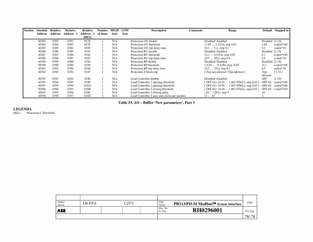
Author Autore LB-DTA L2572 Title
Titolo PR113/PD-M Modbus System Interface ENG
���� Doc. No
N. Doc. RH0296001 Tot. Pag.
78/ 78
Section Absolute Address
Relative Address
Relative Address - 1
Relative Address - 1
(HEX)
Number of items
HIGH byte
LOW byte
Description Comments Range Default Mapped in
40383 0383 0382 017E 1 N/A Protection OV disable Disabled | Enabled Disabled [1 | 0] 40384 0384 0383 017F 1 N/A Protection OV threshold {1.05 … 1.2}Un, step 0.01 1.05 scaled*100 40385 0385 0384 0180 1 N/A Protection OV trip delay time {0.1 … 5}s, step 0.1 0.1 scaled*10 40386 0386 0385 0181 1 N/A Protection RV disable Disabled | Enabled Disabled [1 | 0] 40387 0387 0386 0182 1 N/A Protection RV threshold {0.1 … 0.4}Un, step 0.05 0.1 scaled*100 40388 0388 0387 0183 1 N/A Protection RV trip delay time {0.5 … 30}s, step 0.5 0.5 scaled*10 40389 0389 0388 0184 1 N/A Protection RP disable Disabled | Enabled Disabled [1 | 0] 40390 0390 0389 0185 1 N/A Protection RP threshold {-0.01 … -0.3}Pn, step -0.02 -0.1 scaled*100 40391 0391 0390 0186 1 N/A Protection RP trip delay time {0.5 … 25}s, step 0.1 0.5 scaled*10 40392 0392 0391 0187 1 N/A Protection T block trip [ Trip not allowed | Trip allowed ] Trip
allowed [ 1 | 0 ]
40393 0393 0392 0188 1 N/A Load Controller disable Disabled | Enabled OFF [1 | 0] 40394 0394 0393 0189 1 N/A Load Controller 1 opening threshold [ OFF (0) | {0.50 … 1.00}*ITh(L), step 0.01 ] OFF (0) scaled*100 40395 0395 0394 018A 1 N/A Load Controller 2 opening threshold [ OFF (0) | {0.50 … 1.00}*ITh(L), step 0.01 ] OFF (0) scaled*100 40396 0396 0395 018B 1 N/A Load Controller 2 closing threshold [ OFF (0) | {0.50 … 1.00}*ITh(L), step 0.01 ] OFF (0) scaled*100 40397 0397 0396 018C 1 N/A Load Controller 2 closing delay {10 … 120}s, step 5 10 40398 0398 0397 018D 1 N/A Load Controller 2 max auto-reclosure number {1 … 9} 3
Table 53. AO – Buffer ‘New parameters’, Part 3
LEGENDA Ith(L) Protection L Threshold