pp-r / pp-rct, hot & cold water pipes & fittings...
TRANSCRIPT

SYST EM SYST EM
PP-R / PP-RCT, hot & cold water
©
Pipes & Fittings System
Made inGermany
©
©
©
BQ-Rohrsysteme GmbH Knickweg 1 www.bq-germany.de37688 Beverungen-Würgassen Phone: +49-52 73-38 93-23GERMANY Fax: +49-52 73-38 93-20
Made in Germany
Made in Germany
Made in Germany
Made in Germany
©
M
ade in German
yQualitätbewährte
Stan
d 20
16-0
1

❱❱ Welcome
Founded in 1984 by Mr. Heinz Vössing, Beku Kunststoffwerke began with four extrusion production lines. In 1997, the founder’s son, Markus Vössing, joined the management team. From the beginning of his tenure, Markus started to increase the product range. The company’s policy of providing an exceptional product, exceptionally priced, has led to healthy growth.Beku is still a family owned and operated company – now led by Markus Vössing – and has been able to produce very efficiently as a result of low overheads. There are now three sites with 25 extrusion lines produc-ing pipes and profiles of PVC, PE and PP. The products are sold both with Beku’s branding and in OEM products.Until 2009, Beku produced PP-R pipes solely for other companies. Start-ing in 2010, Beku began developing its own fittings to complement its PP-R pipe system. Since the formation of BQ Rohrsysteme GmbH in 2011, the company has offered a complete PP-R pipe system with PP-R fittings proudly made in Germany.“BQ” stands for best quality – made in Germany – at the best price.
❱❱ Willkommen
Heinz Vössing gründete im Jahr 1984 die Beku Kunststoffwerke GmbH & Co. KG zunächst mit 4 Extrusionsanlagen. 1997 tritt sein Sohn Markus Vössing in die Firma ein und erweitert gezielt die Produktpalette. Die erfolgreiche Firmenpolitik, hervorragende Produkte zu einem fairen Preis zu produzieren, hat zu einem stetigen Wachstum geführt.Dabei ist Beku ein flexibles Familienunternehmen geblieben, das ohne teuren Wasserkopf besonders wettbewerbsfähig produziert. Zwischen-zeitlich werden an den 3 Standorten mit 25 Extrudern Profile und Rohre aus PVC, PE und PP gefertigt. Die Produkte werden zum Teil in eigenem Namen als auch als OEM Produkte vertrieben.Bis 2009 wurden PP-R Rohre ausschließlich für andere Unternehmen im Auftrag gefertigt. Im Jahr 2010 wurde mit dem Aufbau eines eigenen PP-R Fitting-Programms begonnen und damit der Grundstein für ein eigenes PP-R Rohrsystem gelegt.Seit der Gründung der BQ-Rohrsysteme GmbH im Jahr 2011 wird ein komplettes PP-R Rohrsystem produziert, selbst vertrieben und stetig erweitert.„BQ“ steht für bewährte Qualität – made in Germany – zu einem fairen Preis.
❱❱ TABLE OF CONTENTS INHALTSVERZEICHNIS
Company Unternehmen . . . . . . . . . . . . . . . . . . . . . . . . . . . . . . . . . . . . . . . . . . . . . . . . . . 02
Quality Assurance Qualitätssicherung . . . . . . . . . . . . . . . . . . . . . . . . . . . . . . . . . . . . . . . . . . . . . . . . . . . . . 04
Advantages Vorteile . . . . . . . . . . . . . . . . . . . . . . . . . . . . . . . . . . . . . . . . . . . . . . . . . . . . . . . . . . . . . . . . 05
Standards and Regulations Normen und Vorschriften . . . . . . . . . . . . . . . . . . . . . . . . . . . . . . . . . . . . . . . . . . . . . . 06
System Produkte . . . . . . . . . . . . . . . . . . . . . . . . . . . . . . . . . . . . . . . . . . . . . . . . . . . . . . . . . 08
Summary of Models Gesamtübersicht . . . . . . . . . . . . . . . . . . . . . . . . . . . . . . . . . . . . . . . . . . . . . . . . . . . . . . 08
Pressure Pipes Druckrohre . . . . . . . . . . . . . . . . . . . . . . . . . . . . . . . . . . . . . . . . . . . . . . . . . . . . . . . . . . . . . 10
Fittings Verbindungsstücke . . . . . . . . . . . . . . . . . . . . . . . . . . . . . . . . . . . . . . . . . . . . . . . . . . . . . 13
Tools Werkzeuge . . . . . . . . . . . . . . . . . . . . . . . . . . . . . . . . . . . . . . . . . . . . . . . . . . . . . . . . . . . . 19
Maximum Pressures Maximale Drücke . . . . . . . . . . . . . . . . . . . . . . . . . . . . . . . . . . . . . . . . . . . . . . . . . . . . . . 20
Material Properties Materialeigenschaften . . . . . . . . . . . . . . . . . . . . . . . . . . . . . . . . . . . . . . . . . . . . . . . . . 22
Linear Expansion (Examples) Längenausdehnung (Beispiele) . . . . . . . . . . . . . . . . . . . . . . . . . . . . . . . . . . . . . . . . 23
Processing Verarbeitung . . . . . . . . . . . . . . . . . . . . . . . . . . . . . . . . . . . . . . . . . . . . . . . . . . 24
Welding Device and Tool Montage der Schweisswerkzeuge . . . . . . . . . . . . . . . . . . . . . . . . . . . . . . . . . . . . . 26
Welding Process Schweissen . . . . . . . . . . . . . . . . . . . . . . . . . . . . . . . . . . . . . . . . . . . . . . . . . . . . . . . . . . . . 28
Expansion Controls Dehnungsausgleich . . . . . . . . . . . . . . . . . . . . . . . . . . . . . . . . . . . . . . . . . . . . . . . . . . . . 29
Expansion Loop Dehnungsbogen . . . . . . . . . . . . . . . . . . . . . . . . . . . . . . . . . . . . . . . . . . . . . . . . . . . . . . . 30
Pre-Stress Vorspannung . . . . . . . . . . . . . . . . . . . . . . . . . . . . . . . . . . . . . . . . . . . . . . . . . . . . . . . . . . 31
Health and Safety Regulations Arbeitsschutzbestimmungen . . . . . . . . . . . . . . . . . . . . . . . . . . . . . . . . . . . . . . . . . . . 34
Installation Montage . . . . . . . . . . . . . . . . . . . . . . . . . . . . . . . . . . . . . . . . . . . . . . . . . . . . . . . . . 35
Linear Expansion Längenausdehnung . . . . . . . . . . . . . . . . . . . . . . . . . . . . . . . . . . . . . . . . . . . . . . . . . . . . 35
Recommended Spans Empfohlene Befestigungen . . . . . . . . . . . . . . . . . . . . . . . . . . . . . . . . . . . . . . . . . . . . 37
Insulation Isolierung / Dämmung . . . . . . . . . . . . . . . . . . . . . . . . . . . . . . . . . . . . . . . . . . . . . . . . 38
Pressure Test Druckprüfung . . . . . . . . . . . . . . . . . . . . . . . . . . . . . . . . . . . . . . . . . . . . . . . . . . . . . . . . . . 40
Test Protocols Test Protokolle . . . . . . . . . . . . . . . . . . . . . . . . . . . . . . . . . . . . . . . . . . . . . . . . . . . . . . . . 44
Transport and Storage Transport und Lagerung . . . . . . . . . . . . . . . . . . . . . . . . . . . . . . . . . . . . . . . . . . . . . . . 46
Planning and Design Planung und Aufbau . . . . . . . . . . . . . . . . . . . . . . . . . . . . . . . . . . . . . . . 47
Minimum Flow Pressures and Calculation of Flow Rates Mindestdurchflussdrücke und kalk. Durchflussraten . . . . . . . . . . . . . . . . . . . . 47
Resistance Coefficients Widerstands-Koeffizienten . . . . . . . . . . . . . . . . . . . . . . . . . . . . . . . . . . . . . . . . . . . . . 48
Pressure Losses from Individual Resistance Druckverluste durch eigenen Widerstand . . . . . . . . . . . . . . . . . . . . . . . . . . . . . . 49
Maximum Flow Rate Max. Durchfluss . . . . . . . . . . . . . . . . . . . . . . . . . . . . . . . . . . . . . . . . . . . . . . . . . . . . . . . 50
Pipe Friction Gradient / Flow Speed Rohrwiderstand / Fließgeschwindigkeit . . . . . . . . . . . . . . . . . . . . . . . . . . . . . . . . 52
Chemical Resistance of PP Chemische Beständigkeit von PP . . . . . . . . . . . . . . . . . . . . . . . . . . . . . . . . . . . . . . 64
Calculation Fundamentals Kalkulationsgrundlagen . . . . . . . . . . . . . . . . . . . . . . . . . . . . . . . . . . . . . . . . . . . . . . . . 67
32 ©
C O M P A N Y S Y S T E M P R O C E S S I N G I N S T A L L A T I O N P L A N N I N G C O M P A N Y S Y S T E M P R O C E S S I N G I N S T A L L A T I O N P L A N N I N GCOM PA N Y COM PA N Y
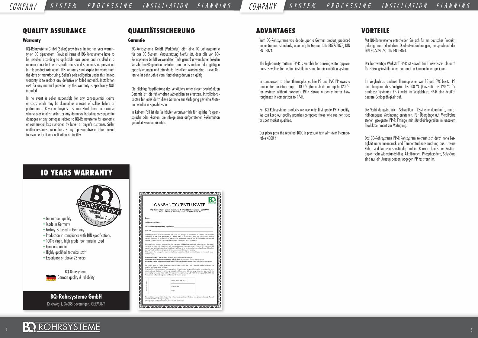
10 YEARS WARRANTY
• Guaranteed quality • Made in Germany • Factory is based in Germany • Production in compliance with DIN specifications • 100% virgin, high grade raw material used • European origin • Highly qualified technical staff • Experience of above 25 years
BQ-Rohrsysteme
German quality & reliability
BQ-Rohrsysteme GmbHKnickweg 1, 37688 Beverungen, GERMANY
Made in Germanyquality
reliable
ADVANTAGESWith BQ-Rohrsysteme you decide upon a German product, produced under German standards, according to German DIN 8077/8078, DIN EN 15874.
The high-quality material PP-R is suitable for drinking water applica-tions as well as for heating installations and for air-condition systems.
In comparison to other thermoplastics like PE and PVC PP owns a temperature resistance up to 100 °C (for a short time up to 120 °C for systems without pressure). PP-R shows a clearly better blow toughness in comparison to PP-H.
For BQ-Rohrsysteme products we use only first grade PP-R quality. We can keep our quality promises compared those who use non spec or spot market qualities.
Our pipes pass the required 1000 h pressure test with over incompa-rable 4000 h.
VORTEILEMit BQ-Rohrsysteme entscheiden Sie sich für ein deutsches Produkt, gefertigt nach deutschen Qualitätsanforderungen, entsprechend der DIN 8077/8078, DIN EN 15874.
Der hochwertige Werkstoff PP-R ist sowohl für Trinkwasser- als auch für Heizungsinstallationen und auch in Klimaanlagen geeignet.
Im Vergleich zu anderen Thermoplasten wie PE und PVC besitzt PP eine Temperaturbeständigkeit bis 100 °C (kurzzeitig bis 120 °C für drucklose Systeme). PP-R weist im Vergleich zu PP-H eine deutlich bessere Schlagzähigkeit auf.
Die Verbindungstechnik - Schweißen - lässt eine dauerhafte, mate-rialhomogene Verbindung entstehen. Für Übergänge auf Metallrohre stehen geeignete PP-R Fittinge mit Metalleinlegeteilen in unserem Produktsortiment zur Verfügung.
Das BQ-Rohrsysteme PP-R Rohrsystem zeichnet sich durch hohe Fes-tigkeit unter Innendruck und Temperaturbeanspruchung aus. Unsere Rohre sind korrosionsbeständig und im Bereich chemischer Bestän-digkeit sehr widerstandsfähig. Alkalilaugen, Phosphorsäure, Salzsäure sind nur ein Auszug dessen wogegen PP resistent ist.
QUALITY ASSURANCEWarranty
BQ-Rohrsysteme GmbH (Seller) provides a limited ten year warran-ty on BQ pipesystem. Provided items of BQ-Rohrsysteme have to be installed according to applicable local codes and installed in a manner consistent with specifications and standards as prescribed in this product catalogue. This warranty shall expire ten years from the date of manufacturing. Seller‘s sole obligation under this limited warranty is to replace any defective or failed material. Installation cost for any material provided by this warranty is specifically NOT included.
In no event is seller responsible for any consequential claims or costs which may be claimed as a result of sellers failure or performance. Buyer or buyer’s customer shall have no recourse whatsoever against seller for any damages including consequential damages or any damages related to BQ-Rohrsysteme for economic or commercial loss sustained by buyer or buyer’s customer. Seller neither assumes nor authorizes any representative or other person to assume for it any obligation or liability.
QUALITÄTSSICHERUNGGarantie
BQ-Rohrsysteme GmbH (Verkäufer) gibt eine 10 Jahresgarantie für das BQ System. Voraussetzung hierfür ist, dass alle von BQ-Rohrsysteme GmbH verwendeten Teile gemäß anwendbaren lokalen Vorschriften/Regularien installiert und entsprechend der gültigen Spezifizierungen und Standards installiert worden sind. Diese Ga-rantie ist zehn Jahre vom Herstellungsdatum an gültig.
Die alleinige Verpflichtung des Verkäufers unter dieser beschränkten Garantie ist, die fehlerhaften Materialien zu ersetzen. Installations-kosten für jedes durch diese Garantie zur Verfügung gestellte Mate-rial werden ausgeschlossen.
In keinem Fall ist der Verkäufer verantwortlich für jegliche Folgean-sprüche oder -kosten, die infolge einer aufgetretenen Reklamation gefordert werden könnten.
BQ-Rohrsysteme GmbH · Knickweg 1 · D-37688 Beverungen / GERMANY Phone +49-5645-78778-70 · Fax: +49-5645-78778-90
Owner: _________________________________________________________________________ Building site address: ______________________________________________________________ Installation company (stamp, signature): ______________________________________________ Start-up: ________________________________________________________________________ BQ-Rohrsysteme GmbH manufactures all pipes and fittings in accordance with German DIN confirming a 10 year guarantee of service life in accordance with the permissible working pressure/temperature of their stated specifications. Within the scope of this, BQ will supply replacement material pipe and fittings if damages are traceable to materials faults and defects. Furthermore, we have covered a product liability insurance with a reputated German insurance company. Compliance with existing DIN standards, our planning and working instructions as well as professional installation by an approved skilled company are compulsory for any indemnification. In case of any damage – provided that the damage has verifiably been caused by manufacturing resp. material faults – you will be indemnified up to the below mentioned amounts: 1. Product liability: 5.000.000 Euro for bodily injury and property damage 2. Costs for installation and disassembly: 500.000 Euro without any consequential charges 3. Damages caused to the environment: 5.000.000 Euro caused by products influencing soil, air or water The liability starts on the day of installation and will end 5 years after the production date of the installed BQ-Rohrsysteme products. Please fill out the warranty certificate after installation has been completed and checked by an BQ-representative. Please send the warranty along with the completed pressure test sheet to BQ-Rohrsysteme GmbH, Knickweg 1, D-37688 Beverungen, GERMANY. BQ-Rohrsysteme will countersign the certificate and return it to you.
Rece
ived
at B
Q
Policy-No: 28.121.518011 Handled by: Date:
This certificate is only valid if the carrying-out company confirms with stamp and signature the duly effected installation and countersigned by BQ (No legal right can be derived from this warranty certificate)
BQ-Rohrsysteme GmbH · Knickweg 1 · D-37688 Beverungen / GERMANY Phone +49-5645-78778-70 · Fax: +49-5645-78778-90
Owner: _________________________________________________________________________ Building site address: ______________________________________________________________ Installation company (stamp, signature): ______________________________________________ Start-up: ________________________________________________________________________ BQ-Rohrsysteme GmbH manufactures all pipes and fittings in accordance to German DIN standard confirming a 10 year guarantee of service life in accordance with the permissible working pressure/temperature of their stated specifications. Within the scope of this, BQ will supply replacement material, pipe and fittings if damages are traceable to materials faults and defects. Additionally our product is covered under a product liability insurance with a top German (European) insurance company. All installations will have to be made in compliance with existing DIN standards, BQ planning and working instructions. Installations will have to be performed by trained professional installers and approved installation companies for our guarantee and insurance to apply. If it is proven that damage has occurred due to manufacturing defects or materials, the insurance will cover the following: 1. Product liability: 5.000.000 Euro for bodily injury and property damage 2. Costs for installation and disassembly: 500.000 Euro excluding any consequential charges 3. Damages caused to the environment: 5.000.000 Euro caused by products influencing soil, air or water The liability starts on the day of delivery from the plant and will end 5 years after the production date of the installed BQ-Rohrsysteme products. To be eligible for this insurance coverage, please fill out the warranty certificate after installation has been completed and checked by a BQ-representative. Please send this warranty statement along with the completed pressure test sheet to BQ-Rohrsysteme GmbH, Knickweg 1, D-37688 Beverungen, GERMANY. BQ-Rohrsysteme will countersign the certificate and return it to you.
Rece
ived
at B
Q
Policy-No: 49230266127 Handled by: Date:
This certificate is only valid if the carrying-out company confirms with stamp and signature the duly effected installation and countersigned by BQ (No legal right can be derived from this warranty certificate)
54 ©
C O M P A N Y S Y S T E M P R O C E S S I N G I N S T A L L A T I O N P L A N N I N G C O M P A N Y S Y S T E M P R O C E S S I N G I N S T A L L A T I O N P L A N N I N GCOM PA N Y COM PA N Y
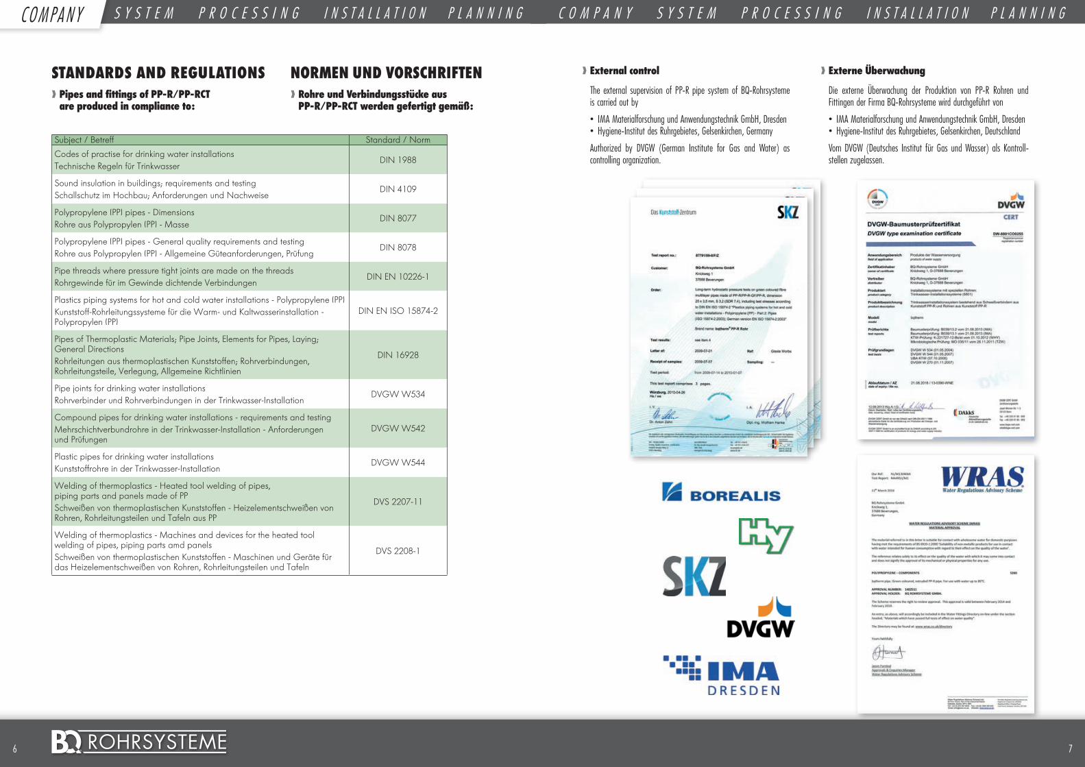
❱❱ External control
The external supervision of PP-R pipe system of BQ-Rohrsysteme is carried out by
• IMA Materialforschung und Anwendungstechnik GmbH, Dresden• Hygiene-Institut des Ruhrgebietes, Gelsenkirchen, Germany
Authorized by DVGW (German Institute for Gas and Water) as controlling organization.
❱❱ Externe Überwachung
Die externe Überwachung der Produktion von PP-R Rohren und Fittingen der Firma BQ-Rohrsysteme wird durchgeführt von
• IMA Materialforschung und Anwendungstechnik GmbH, Dresden• Hygiene-Institut des Ruhrgebietes, Gelsenkirchen, Deutschland
Vom DVGW (Deutsches Institut für Gas und Wasser) als Kontroll-stellen zugelassen.
76 ©
STANDARDS AND REGULATIONS❱❱ Pipes and fittings of PP-R/PP-RCT are produced in compliance to:
Subject / Betreff Standard / Norm
Codes of practise for drinking water installationsTechnische Regeln für Trinkwasser
DIN 1988
Sound insulation in buildings; requirements and testingSchallschutz im Hochbau; Anforderungen und Nachweise
DIN 4109
Polypropylene (PP) pipes - DimensionsRohre aus Polypropylen (PP) - Masse
DIN 8077
Polypropylene (PP) pipes - General quality requirements and testingRohre aus Polypropylen (PP) - Allgemeine Güteanforderungen, Prüfung
DIN 8078
Pipe threads where pressure tight joints are made on the threadsRohrgewinde für im Gewinde dichtende Verbindungen
DIN EN 10226-1
Plastics piping systems for hot and cold water installations - Polypropylene (PP)Kunststoff-Rohrleitungssysteme für die Warm- und Kaltwasserinstallation - Polypropylen (PP)
DIN EN ISO 15874-2
Pipes of Thermoplastic Materials; Pipe Joints, Elements for Pipes, Laying; General DirectionsRohrleitungen aus thermoplastischen Kunststoffen; Rohrverbindungen, Rohrleitungsteile, Verlegung, Allgemeine Richtlinien
DIN 16928
Pipe joints for drinking water installationsRohrverbinder und Rohrverbindungen in der Trinkwasser-Installation
DVGW W534
Compound pipes for drinking water installations - requirements and testingMehrschichtverbundrohre in der Trinkwasser-Installation - Anforderungen und Prüfungen
DVGW W542
Plastic pipes for drinking water installationsKunststoffrohre in der Trinkwasser-Installation
DVGW W544
Welding of thermoplastics - Heated tool welding of pipes, piping parts and panels made of PPSchweißen von thermoplastischen Kunststoffen - Heizelementschweißen von Rohren, Rohrleitungsteilen und Tafeln aus PP
DVS 2207-11
Welding of thermoplastics - Machines and devices for the heated tool welding of pipes, piping parts amd panelsSchweißen von thermoplastischen Kunststoffen - Maschinen und Geräte für das Heizelementschweißen von Rohren, Rohrleitungsteilen und Tafeln
DVS 2208-1
NORMEN UND VORSCHRIFTEN❱❱ Rohre und Verbindungsstücke aus PP-R/PP-RCT werden gefertigt gemäß:
C O M P A N Y S Y S T E M P R O C E S S I N G I N S T A L L A T I O N P L A N N I N G C O M P A N Y S Y S T E M P R O C E S S I N G I N S T A L L A T I O N P L A N N I N GCOM PA N Y
Electrofusion socketHeizwendel-Schweissmuffe
BQ 712... Page / Seite 19
Electrofusion machine for electro-fusion socketsHeizwendel- schweissgerätBQ 858... Page / Seite 19
98 ©
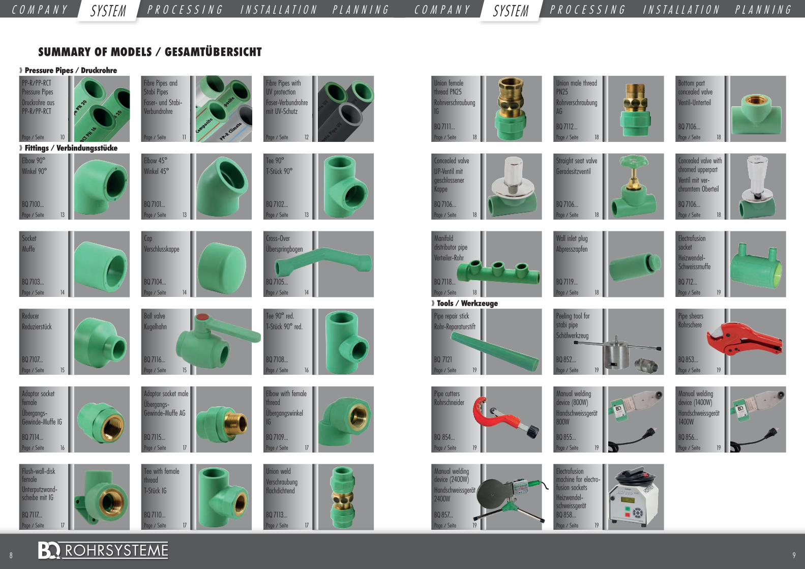
❱❱ Pressure Pipes / Druckrohre
❱❱ Fittings / Verbindungsstücke
❱❱ Tools / Werkzeuge
SUMMARY OF MODELS / GESAMTÜBERSICHT
PP-R/PP-RCT Pressure Pipes Druckrohre aus PP-R/PP-RCT
Elbow 90° Winkel 90°
Pipe repair stickRohr-Reparaturstift
Tee 90° T-Stück 90°
Pipe shears Rohrschere
Pipe cutters Rohrschneider
Manual welding device (800W)Handschweissgerät 800W
Manual welding device (1400W)Handschweissgerät 1400W
Cross-Over Überspringbogen
Bottom part concealed valveVentil-Unterteil
Concealed valve with chromed upperpartVentil mit ver-chromtem Oberteil
Elbow with female threadÜbergangswinkel IG
Fibre Pipes and Stabi PipesFaser- und Stabi-Verbundrohre
Fibre Pipes with UV protectionFaser-Verbundrohre mit UV-Schutz
Elbow 45° Winkel 45°
Peeling tool for stabi pipeSchälwerkzeug
Manual welding device (2400W)Handschweissgerät 2400W
Socket Muffe
Union female thread PN25Rohrverschraubung IG
Manifold distributor pipeVerteiler-Rohr
Concealed valveUP-Ventil mit geschlossener Kappe
Reducer Reduzierstück
Adaptor socket femaleÜbergangs-Gewinde-Muffe IG
Flush-wall-disk female Unterputzwand-scheibe mit IG
Cap Verschlusskappe
Union male thread PN25Rohrverschraubung AG
Wall inlet plugAbpresszapfen
Straight seat valveGeradesitzventil
Adaptor socket maleÜbergangs-Gewinde-Muffe AG
Tee with female thread T-Stück IG
Union weldVerschraubung flachdichtend
Page / Seite 10
BQ 7100... Page / Seite 13
BQ 7121 Page / Seite 19
BQ 7102... Page / Seite 13
BQ 853... Page / Seite 19
BQ 854... Page / Seite 19
BQ 855... Page / Seite 19
BQ 856... Page / Seite 19
BQ 7105... Page / Seite 14
BQ 7106... Page / Seite 18
BQ 7106... Page / Seite 18
Ball valve Kugelhahn
BQ 7116... Page / Seite 15
BQ 7109... Page / Seite 17
Page / Seite 11
Page / Seite 12
BQ 7101... Page / Seite 13
BQ 852... Page / Seite 19
BQ 857... Page / Seite 19
BQ 7103... Page / Seite 14
BQ 7111... Page / Seite 18
BQ 7118... Page / Seite 18
BQ 7106... Page / Seite 18
BQ 7107... Page / Seite 15
BQ 7114... Page / Seite 16
BQ 7117... Page / Seite 17
BQ 7104... Page / Seite 14
BQ 7112... Page / Seite 18
BQ 7119... Page / Seite 18
BQ 7106... Page / Seite 18
Tee 90° red.T-Stück 90° red.
BQ 7108... Page / Seite 16
BQ 7115... Page / Seite 17
BQ 7110... Page / Seite 17
BQ 7113... Page / Seite 17
C O M P A N Y S Y S T E M P R O C E S S I N G I N S T A L L A T I O N P L A N N I N G C O M P A N Y S Y S T E M P R O C E S S I N G I N S T A L L A T I O N P L A N N I N GSYST EM SYST EM
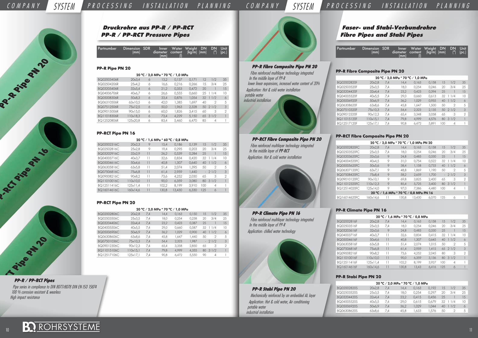
PP-R Fibre Composite Pipe PN 20Fibre reinforced multilayer technology integrated
In the middle layer of PP-R lower linear expansions, increased water content of 20%
Application: Hot & cold water installation potable water
industrial installation
PP-RCT Fibre Composite Pipe PN 20Fibre reinforced multilayer technology integrated
In the middle layer of PP-RCT Application: Hot & cold water installation
PP-R Climate Pipe PN 16Fibre reinforced multilayer technology integrated
In the middle layer of PP-R Application: chilled water technology
PP-R Stabi Pipe PN 20 Mechanically reinforced by an embedded AL layer
Application: Hot & cold water, Air conditioning potable water
industrial installation
Application:
Inhouse sanitary installation potable water
Druckrohre aus PP-R / PP-RCTPP-R / PP-RCT Pressure Pipes
Faser- und Stabi-VerbundrohreFibre Pipes and Stabi Pipes
Partnumber Dimension (mm)
SDR Inner diameter
(mm)
Water content
(l)
Weight (kg/m)
DN (mm)
DN (“)
Unit (pc.)
PP-R Fibre Composite Pipe PN 2020 °C / 2,0 MPa * 70 °C / 1,0 MPa
BQ02002820F 20x2,8 7,4 14,4 0,163 0,158 15 1/2 35BQ02503520F 25x3,5 7,4 18,0 0,254 0,246 20 3/4 25BQ03204420F 32x4,4 7,4 23,2 0,423 0,394 25 1 15BQ04005520F 40x5,5 7,4 29,0 0,660 0,613 32 1 1/4 10BQ05006920F 50x6,9 7,4 36,2 1,029 0,955 40 1 1/2 6BQ06308620F 63x8,6 7,4 45,8 1,647 1,500 50 2 5BQ07510320F 75x10,3 7,4 54,4 2,323 2,135 50 2 1/2 3BQ09012320F 90x12,3 7,4 65,4 3,348 3,058 65 3 2BQ11015120F 110x15,1 7,4 79,8 4,999 4,576 80 3 1/2 1BQ12517120F 125x17,1 7,4 90,8 6,472 5,891 100 4 1
PP-RCT Fibre Composite Pipe PN 20 20 °C / 2,0 MPa * 70 °C / 1,0 MPa PN 20
BQ02002820FC 20x2,8 7,4 14,4 0,163 0,158 15 1/2 35BQ02503520FC 25x3,5 7,4 18,0 0,254 0,246 20 3/4 25BQ03203620FC 32x3,6 9 24,8 0,483 0,330 25 1 15BQ04004520FC 40x4,5 9 31,0 0,754 0,522 32 1 1/4 10BQ05005620FC 50x5,6 9 38,4 1,158 0,733 40 1 1/2 6BQ06307120FC 63x7,1 9 48,8 1,869 1,190 50 2 5BQ07508420FC 75x8,4 9 58,2 2,659 1,700 - 2 1/2 3BQ09010120FC 90x10,1 9 69,8 3,825 2,400 65 3 2BQ11012320FC 110x12,3 9 85,4 5,725 3,400 80 3 1/2 1BQ12514020FC 125x14,0 9 97,0 7,386 4,480 100 4 1
20 °C / 1,6 MPa * 70 °C / 0,8 MPa PN 16BQ16014620FC 160x14,6 11 130,8 13,430 6,070 125 6 1
PP-R Climate Pipe PN 1620 °C / 1,6 MPa * 70 °C / 0,8 MPa
BQ02002816F 20x2,8 7,4 14,4 0,163 0,158 15 1/2 35BQ02503516F 25x3,5 7,4 18,0 0,254 0,246 20 3/4 25BQ03203616F 32x3,6 9 24,8 0,483 0,330 25 1 15BQ04003716F 40x3,7 11 32,6 0,834 0,415 32 1 1/4 10BQ05004616F 50x4,6 11 40,8 1,307 0,645 40 1 1/2 6BQ06305816F 63x5,8 11 51,4 2,074 1,015 50 2 5BQ07506816F 75x6,8 11 61,4 2,959 1,415 65 2 1/2 3BQ09008216F 90x8,2 11 73,6 4,252 2,045 80 3 2BQ11010016F 110x10,0 11 90,0 6,359 3,136 80 3 1/2 1BQ12511416F 125x11,4 11 102,2 8,199 3,927 100 4 1BQ16014616F 160x14,6 11 130,8 13,43 6,416 125 6 1
PP-R Stabi Pipe PN 2020 °C / 2,0 MPa * 70 °C / 1,0 MPa
BQ02002820S 20x2,8 7,4 14,4 0,163 0,192 15 1/2 35BQ02503520S 25x3,5 7,4 18,0 0,254 0,297 20 3/4 25BQ03204420S 32x4,4 7,4 23,2 0,415 0,456 25 1 15BQ04005520S 40x5,5 7,4 29,0 0,615 0,679 32 1 1/4 10BQ05006920S 50x6,9 7,4 36,2 1,029 1,044 40 1 1/2 6BQ06308620S 63x8,6 7,4 45,8 1,633 1,576 50 2 5
Partnumber Dimension (mm)
SDR Inner diameter
(mm)
Water content
(l)
Weight (kg/m)
DN (mm)
DN (“)
Unit (pc.)
PP-R Pipe PN 2020 °C / 2,0 MPa * 70 °C / 1,0 MPa
BQ02003406R 20x3,4 6 13,2 0,137 0,171 12 1/2 35BQ02504206R 25x4,2 6 16,6 0,216 0,266 15 3/4 25BQ03205406R 32x5,4 6 21,2 0,353 0,472 20 1 15BQ04006706R 40x6,7 6 26,6 0,555 0,660 25 1 1/4 10BQ05008306R 50x8,3 6 33,4 0,876 1,054 32 1 1/2 6BQ06310506R 63x10,5 6 42,0 1,385 1,697 40 2 5BQ07512506R 75x12,5 6 50,0 1,963 2,328 50 2 1/2 3BQ09015006R 90x15,0 6 60,0 1,826 3,415 60 3 2BQ11018306R 110x18,3 6 73,4 4,229 5,150 65 3 1/2 1BQ12520806R 125x20,8 6 83,4 5,460 6,470 85 4 1
PP-RCT Pipe PN 1620 °C / 1,6 MPa * 60 °C / 0,8 MPa
BQ02002316C 20x2,3 9 15,4 0,186 0,139 15 1/2 35BQ02502816C 25x2,8 9 19,4 0,295 0,203 20 3/4 25BQ03202916C 32x2,9 11 26,2 0,539 0,284 25 1 15BQ04003716C 40x3,7 11 32,6 0,834 0,420 32 1 1/4 10BQ05004616C 50x4,6 11 40,8 1,307 0,640 40 1 1/2 6BQ06305816C 63x5,8 11 51,4 2,074 1,395 50 2 5BQ07506816C 75x6,8 11 61,4 2,959 1,440 - 2 1/2 3BQ09008216C 90x8,2 11 73,6 4,252 2,030 65 3 2BQ11010016C 110x10,0 11 90,0 6,359 3,080 80 3 1/2 1BQ12511416C 125x11,4 11 102,2 8,199 3,910 100 4 1BQ16014616C 160x14,6 11 130,8 13,430 6,330 125 6 1
PP-RCT Pipe PN 20 20 °C / 2,0 MPa * 70 °C / 1,0 MPa
BQ02002806C 20x2,8 7,4 14,4 0,163 0,150 15 1/2 35BQ02503506C 25x3,5 7,4 18,0 0,254 0,238 20 3/4 25BQ03204406C 32x4,4 7,4 23,2 0,423 0,387 25 1 15BQ04005506C 40x5,5 7,4 29,0 0,660 0,587 32 1 1/4 10BQ05006906C 50x6,9 7,4 36,2 1,029 0,900 40 1 1/2 6BQ06308606C 63x8,6 7,4 45,8 1,647 1,440 50 2 5BQ07501036C 75x10,3 7,4 54,4 2,323 1,987 - 2 1/2 3BQ09012306C 90x12,3 7,4 65,4 3,358 2,850 65 3 2BQ11015106C 110x15,1 7,4 79,8 4,999 4,355 80 3 1/2 1BQ12517106C 125x17,1 7,4 90,8 6,472 5,550 90 4 1
PP-R / PP-RCT PipesPipe series in compliance to DIN 8077/8078 DIN EN ISO 15874
100 % corrosion resistant & wearless High impact resistance
1110 ©
C O M P A N Y S Y S T E M P R O C E S S I N G I N S T A L L A T I O N P L A N N I N G C O M P A N Y S Y S T E M P R O C E S S I N G I N S T A L L A T I O N P L A N N I N GSYST EM SYST EM
Faser-Verbundrohre mit UV-SchutzFibre Pipes with UV protection
Partnumber Dimension (mm)
SDR Inner diameter
(mm)
Water content
(l)
Weight (kg/m)
DN (mm)
DN (“)
Unit (pc.)
PP-R Fibre Composite Pipe PN 20 UV20 °C / 2,0 MPa * 70 °C / 1,0 MPa
BQ02002820FUV 20x2,8 7,4 14,4 0,163 0,158 15 1/2 35BQ02503520FUV 25x3,5 7,4 18,0 0,254 0,246 20 3/4 25BQ03204420FUV 32x4,4 7,4 23,2 0,423 0,394 25 1 15BQ04005520FUV 40x5,5 7,4 29,0 0,660 0,613 32 1 1/4 10BQ05006920FUV 50x6,9 7,4 36,2 1,029 0,955 40 1 1/2 6BQ06308620FUV 63x8,6 7,4 45,8 1,647 1,500 50 2 5BQ07510320FUV 75x10,3 7,4 54,4 2,323 2,135 50 2 1/2 3BQ09012320FUV 90x12,3 7,4 65,4 3,348 3,058 65 3 2BQ11015120FUV 110x15,1 7,4 79,8 4,999 4,576 80 3 1/2 1BQ12517120FUV 125x17,1 7,4 90,8 6,472 5,891 100 4 1
PP-RCT Fibre Composite Pipe PN 20 UV20 °C / 2,0 MPa * 70 °C / 1,0 MPa PN 20
BQ02002820FCUV 20x2,8 7,4 14,4 0,163 0,158 15 1/2 35BQ02503520FCUV 25x3,5 7,4 18,0 0,254 0,246 20 3/4 25BQ03203620FCUV 32x3,6 9 24,8 0,483 0,330 25 1 15BQ04004520FCUV 40x4,5 9 31,0 0,754 0,522 32 1 1/4 10BQ05005620FCUV 50x5,6 9 38,4 1,158 0,733 40 1 1/2 6BQ06307120FCUV 63x7,1 9 48,8 1,869 1,190 50 2 5BQ07508420FCUV 75x8,4 9 58,2 2,659 1,700 - 2 1/2 3BQ09010120FCUV 90x10,1 9 69,8 3,825 2,400 65 3 2BQ11012320FCUV 110x12,3 9 85,4 5,725 3,400 80 3 1/2 1BQ12514020FCUV 125x14,0 9 97,0 7,386 4,480 100 4 1
20 °C / 1,6 MPa * 70 °C / 0,8 MPa PN 16BQ16014620FCUV 160x14,6 11 130,8 13,430 6,070 125 6 1
PP-R Climate Pipe PN 16 UV20 °C / 1,6 MPa * 70 °C / 0,8 MPa
BQ02002816FUV 20x2,8 7,4 14,4 0,163 0,158 15 1/2 35BQ02503516FUV 25x3,5 7,4 18,0 0,254 0,246 20 3/4 25BQ03203616FUV 32x3,6 9 24,8 0,483 0,330 25 1 15BQ04003716FUV 40x3,7 11 32,6 0,834 0,415 32 1 1/4 10BQ05004616FUV 50x4,6 11 40,8 1,307 0,645 40 1 1/2 6BQ06305816FUV 63x5,8 11 51,4 2,074 1,015 50 2 5BQ07506816FUV 75x6,8 11 61,4 2,959 1,415 65 2 1/2 3BQ09008216FUV 90x8,2 11 73,6 4,252 2,045 80 3 2BQ11010016FUV 110x10,0 11 90,0 6,359 3,136 80 3 1/2 1BQ12511416FUV 125x11,4 11 102,2 8,199 3,927 100 4 1BQ16014616FUV 160x14,6 11 130,8 13,43 6,416 125 6 1
Partnumber Dimension
BQ710020 20 mmBQ710025 25 mmBQ710032 32 mmBQ710040 40 mmBQ710050 50 mmBQ710063 63 mmBQ710075 75 mmBQ710090 90 mmBQ7100110 110 mmBQ7100125 125 mmBQ7100160 160 mm
BQ710120 20 mmBQ710125 25 mmBQ710132 32 mmBQ710140 40 mmBQ710150 50 mmBQ710163 63 mmBQ710175 75 mmBQ710190 90 mmBQ7101110 110 mmBQ7101125 125 mmBQ7101160 160 mm
BQ710220 20/20/20BQ710225 25/25/25BQ710232 32/32/32BQ710240 40/40/40BQ710250 50/50/50BQ710263 63/63/63BQ710275 75/75/75BQ710290 90/90/90BQ7102110 110/110/110BQ7102125 125/125/125BQ7102160 160/160/160
Fittings aus PP-R PN25PP-R Fittings PN25
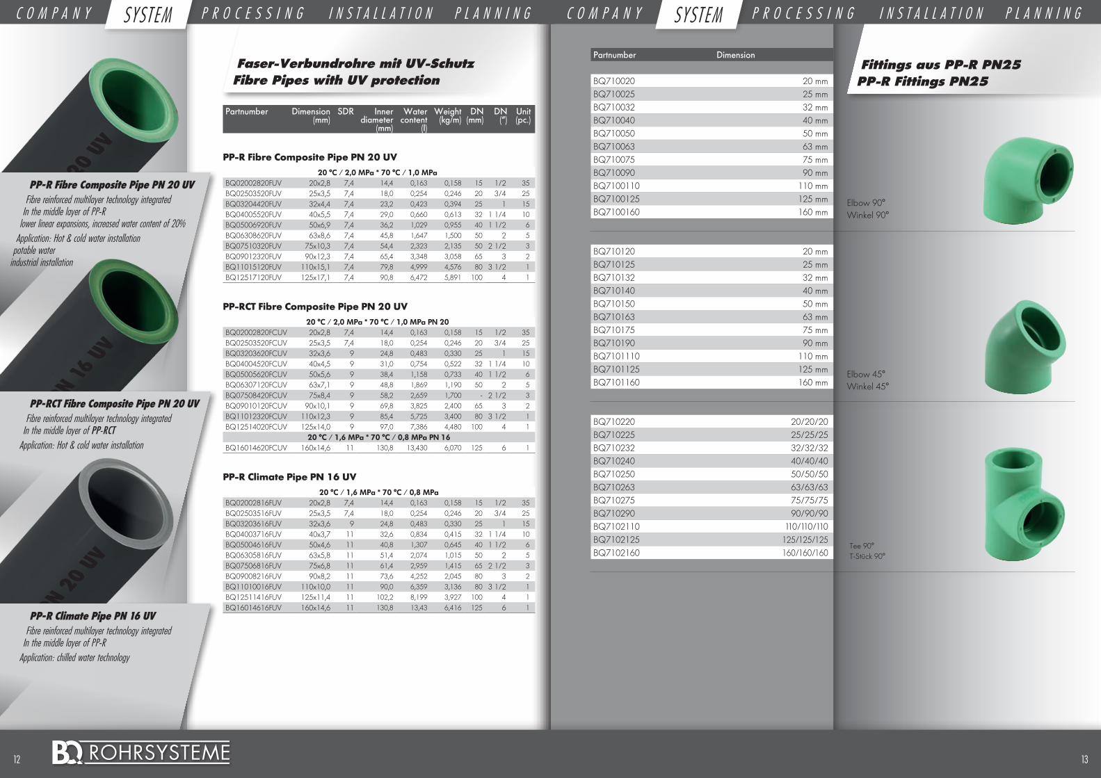
Elbow 90° Winkel 90°
Elbow 45°Winkel 45°
Tee 90°T-Stück 90°
PP-R Fibre Composite Pipe PN 20 UVFibre reinforced multilayer technology integrated
In the middle layer of PP-R lower linear expansions, increased water content of 20%
Application: Hot & cold water installation potable water
industrial installation
PP-RCT Fibre Composite Pipe PN 20 UVFibre reinforced multilayer technology integrated
In the middle layer of PP-RCT Application: Hot & cold water installation
PP-R Climate Pipe PN 16 UVFibre reinforced multilayer technology integrated
In the middle layer of PP-R Application: chilled water technology
1312 ©
C O M P A N Y S Y S T E M P R O C E S S I N G I N S T A L L A T I O N P L A N N I N G C O M P A N Y S Y S T E M P R O C E S S I N G I N S T A L L A T I O N P L A N N I N GSYST EM SYST EM
Partnumber Dimension
BQ710320 20 mmBQ710325 25 mmBQ710332 32 mmBQ710340 40 mmBQ710350 50 mmBQ710363 63 mmBQ710375 75 mmBQ710390 90 mmBQ7103110 110 mmBQ7103125 125 mmBQ7103160 160 mm
BQ710420 20 mmBQ710425 25 mmBQ710432 32 mmBQ710440 40 mmBQ710450 50 mmBQ710463 63 mmBQ710475 75 mmBQ710490 90 mmBQ7104110 110 mmBQ7104125 125 mmBQ7104160 160 mm
BQ710520 20 mmBQ710525 25 mmBQ710532 32 mm
Partnumber Dimension
BQ71072520 25/20BQ71073220 32/20BQ71073225 32/25BQ71074025 40/25BQ71074032 40/32BQ71075025 50/25BQ71075032 50/32BQ71075040 50/40BQ71076325 63/25BQ71076332 63/32BQ71076340 63/40BQ71076350 63/50BQ71077550 75/50BQ71077563 75/63BQ71079063 90/63BQ71079075 90/75BQ710711063 110/63BQ710711075 110/75BQ710711090 110/90BQ7107125110 125/110BQ7107160110 160/110BQ7107160125 160/125
BQ711620 20 mmBQ711625 25 mmBQ711632 32 mmBQ711640 40 mmBQ711650 50 mmBQ711663 63 mm
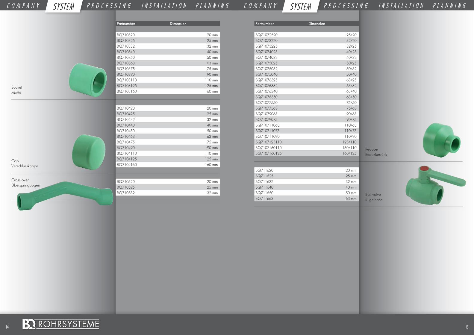
CapVerschlusskappe
SocketMuffe
Cross-overÜberspringbogen
Ball valveKugelhahn
ReducerReduzierstück
1514 ©
C O M P A N Y S Y S T E M P R O C E S S I N G I N S T A L L A T I O N P L A N N I N G C O M P A N Y S Y S T E M P R O C E S S I N G I N S T A L L A T I O N P L A N N I N GSYST EM SYST EM
Partnumber Dimension
BQ711520012 20 x 1/2”BQ711525012 25 x 1/2”BQ711525034 25 x 3/4”BQ711532034 32 x 3/4”BQ711532100 32 x 1”BQ711540114 40 x 1 1/4”BQ711550112 50 x 1 1/2”BQ711563200 63 x 2”BQ711575212 75 x 2 1/2”BQ711590300 90 x 3”BQ7115110400 110 x 4”
BQ710920012 20 x 1/2”BQ710925012 25 x 1/2”BQ710925034 25 x 3/4”BQ710932034 32 x 3/4”BQ710932100 32 x 1”
BQ711720012 20 x 1/2”BQ711725012 25 x 1/2”BQ711725034 25 x 3/4”
BQ711020012 20 x 1/2”BQ711025012 25 x 1/2”BQ711025034 25 x 3/4”BQ711032034 32 x 3/4”BQ711032100 32 x 1”
BQ711320 20 mmBQ711325 25 mmBQ711332 32 mmBQ711340 40 mmBQ711350 50 mmBQ711363 63 mmBQ711375 75 mm
Partnumber Dimension
BQ7108252025 25/20/25BQ7108322032 32/20/32BQ7108322532 32/25/32BQ7108402040 40/20/40BQ7108402540 40/25/40BQ7108403240 40/32/40BQ7108502550 50/25/50BQ7108503250 50/32/50BQ7108504050 50/40/50BQ7108632563 63/25/63BQ7108633263 63/32/63BQ7108634063 63/40/63BQ7108635063 63/50/63BQ7108753275 75/32/75BQ7108754075 75/40/75BQ7108755075 75/50/75BQ7108756375 75/63/75BQ7108905090 90/50/90BQ7108906390 90/63/90BQ7108907590 90/75/90BQ710811063110 110/63/110BQ710811075110 110/75/110BQ710811090110 110/90/110BQ710816090160 160/90/160BQ7108160110160 160/110/160
BQ711420012 20 x 1/2”BQ711425012 25 x 1/2”BQ711425034 25 x 3/4”BQ711432034 32 x 3/4”BQ711432100 32 x 1”BQ711440114 40 x 1 1/4”BQ711450112 50 x 1 1/2”BQ711463200 63 x 2”BQ711475212 75 x 2 1/2”BQ711490300 90 x 3”BQ7114110400 110 x 4”
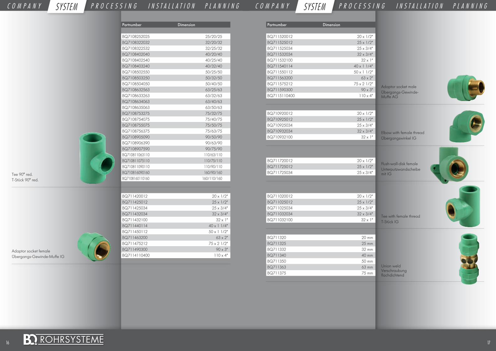
Tee 90° red.T-Stück 90° red.
Adaptor socket femaleÜbergangs-Gewinde-Muffe IG
Tee with female threadT-Stück IG
Union weld Verschraubung flachdichtend
Elbow with female threadÜbergangswinkel IG
Flush-wall-disk femaleUnterputzwandscheibe mit IG
Adaptor socket maleÜbergangs-Gewinde-Muffe AG
1716 ©
C O M P A N Y S Y S T E M P R O C E S S I N G I N S T A L L A T I O N P L A N N I N G C O M P A N Y S Y S T E M P R O C E S S I N G I N S T A L L A T I O N P L A N N I N GSYST EM SYST EM
Tools Werkzeuge
Partnumber Dimension
BQ711120012 20 x 1/2”BQ711125034 25 x 3/4”BQ711132100 32 x 1”BQ711140114 40 x 1 1/4”BQ711150112 50 x 1 1/2”BQ711163200 63 x 2”BQ711175212 75 x 2 1/2”
BQ711220012 20 x 1/2”BQ711225034 25 x 3/4”BQ711232100 32 x 1”BQ711240114 40 x 1 1/4”BQ711250112 50 x 1 1/2”BQ711263200 63 x 2”BQ711275212 75 x 2 1/2”
BQ710620034 20 x 3/4”BQ710625034 25 x 3/4”BQ710632034 32 x 3/4”
BQ710620034B 20 x 3/4”BQ710625034B 25 x 3/4”BQ710632034B 32 x 3/4”
BQ710620034C 20 x 3/4”BQ710625034C 25 x 3/4”BQ710632034C 32 x 3/4”
BQ710620034D 20 x 3/4”BQ710625034D 25 x 3/4”BQ710632034D 32 x 3/4”
BQ711863323 63 x 32 x 3
BQ711912 1/2”
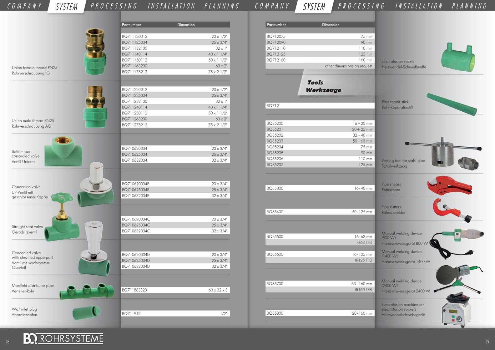
Union male thread PN25Rohrverschraubung AG
Concealed valveUP-Ventil mit geschlossener Kappe
Bottom part concealed valveVentil-Unterteil
Straight seat valveGeradsitzventil
Concealed valve with chromed upperpartVentil mit verchromtem Oberteil
Union female thread PN25Rohrverschraubung IG
Partnumber Dimension
BQ712075 75 mmBQ712090 90 mmBQ712110 110 mmBQ712125 125 mmBQ712160 160 mm
other dimensions on request
Manifold distributor pipe Verteiler-Rohr
Wall inlet plug Abpresszapfen
BQ7121
BQ85200 16 + 20 mm
Peeling tool for stabi pipeSchälwerkzeug
BQ85201 20 + 25 mmBQ85202 32 + 40 mmBQ85203 50 + 63 mmBQ85204 75 mmBQ85205 90 mmBQ85206 110 mmBQ85207 125 mm
Pipe shearsRohrschereBQ85300 16 - 40 mm
Pipe cuttersRohrschneiderBQ85400 50 - 125 mm
Manual welding device (800 W)Handschweissgerät 800 W
Manual welding device (1400 W)Handschweissgerät 1400 W
BQ85500 16 - 63 mm(R63 TFE)
BQ85600 16 - 125 mm(R125 TFE)
Manual welding device (2400 W)Handschweissgerät 2400 W
BQ85700 63 - 160 mm(R160 TFE)
Electrofusion machine for electrofusion socketsHeizwendelschweissgerätBQ85800 20 - 160 mm
Pipe repair stickRohr-Reparaturstift
Electrofusion socket Heizwendel-Schweißmuffe
1918 ©
C O M P A N Y S Y S T E M P R O C E S S I N G I N S T A L L A T I O N P L A N N I N G C O M P A N Y S Y S T E M P R O C E S S I N G I N S T A L L A T I O N P L A N N I N GSYST EM SYST EM
2120 ©
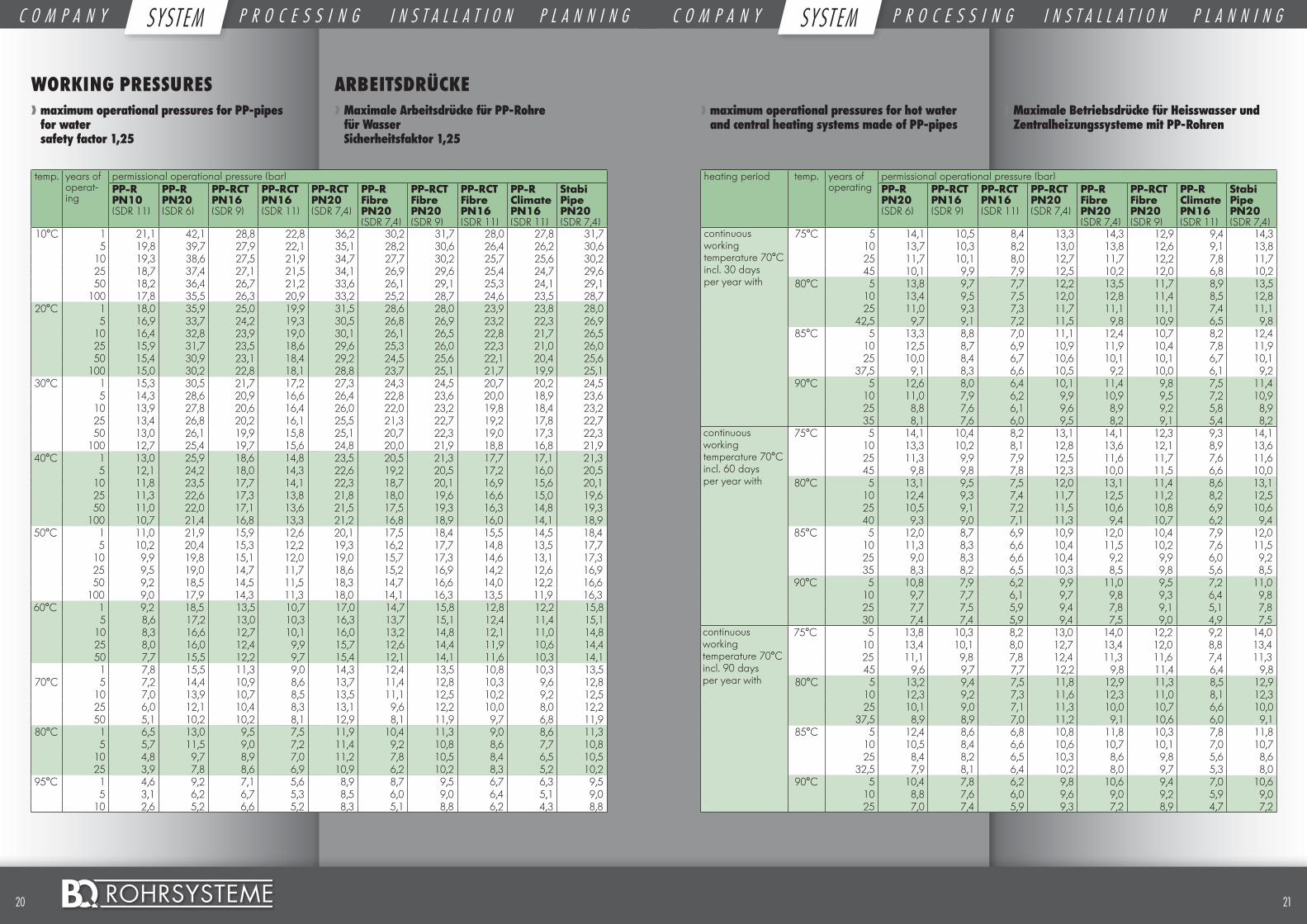
WORKING PRESSURES❱❱ maximum operational pressures for PP-pipes for water safety factor 1,25
ARBEITSDRÜCKE❱❱ Maximale Arbeitsdrücke für PP-Rohre für Wasser Sicherheitsfaktor 1,25
temp. years of operat-ing
permissional operational pressure (bar)PP-R PN10 (SDR 11)
PP-R PN20 (SDR 6)
PP-RCT PN16 (SDR 9)
PP-RCT PN16 (SDR 11)
PP-RCT PN20 (SDR 7,4)
PP-R Fibre PN20 (SDR 7,4)
PP-RCT Fibre PN20 (SDR 9)
PP-RCT Fibre PN16 (SDR 11)
PP-R Climate PN16 (SDR 11)
Stabi Pipe PN20 (SDR 7,4)
10°C 1 21,1 42,1 28,8 22,8 36,2 30,2 31,7 28,0 27,8 31,75 19,8 39,7 27,9 22,1 35,1 28,2 30,6 26,4 26,2 30,6
10 19,3 38,6 27,5 21,9 34,7 27,7 30,2 25,7 25,6 30,225 18,7 37,4 27,1 21,5 34,1 26,9 29,6 25,4 24,7 29,650 18,2 36,4 26,7 21,2 33,6 26,1 29,1 25,3 24,1 29,1
100 17,8 35,5 26,3 20,9 33,2 25,2 28,7 24,6 23,5 28,720°C 1 18,0 35,9 25,0 19,9 31,5 28,6 28,0 23,9 23,8 28,0
5 16,9 33,7 24,2 19,3 30,5 26,8 26,9 23,2 22,3 26,910 16,4 32,8 23,9 19,0 30,1 26,1 26,5 22,8 21,7 26,525 15,9 31,7 23,5 18,6 29,6 25,3 26,0 22,3 21,0 26,050 15,4 30,9 23,1 18,4 29,2 24,5 25,6 22,1 20,4 25,6
100 15,0 30,2 22,8 18,1 28,8 23,7 25,1 21,7 19,9 25,130°C 1 15,3 30,5 21,7 17,2 27,3 24,3 24,5 20,7 20,2 24,5
5 14,3 28,6 20,9 16,6 26,4 22,8 23,6 20,0 18,9 23,610 13,9 27,8 20,6 16,4 26,0 22,0 23,2 19,8 18,4 23,225 13,4 26,8 20,2 16,1 25,5 21,3 22,7 19,2 17,8 22,750 13,0 26,1 19,9 15,8 25,1 20,7 22,3 19,0 17,3 22,3
100 12,7 25,4 19,7 15,6 24,8 20,0 21,9 18,8 16,8 21,940°C 1 13,0 25,9 18,6 14,8 23,5 20,5 21,3 17,7 17,1 21,3
5 12,1 24,2 18,0 14,3 22,6 19,2 20,5 17,2 16,0 20,510 11,8 23,5 17,7 14,1 22,3 18,7 20,1 16,9 15,6 20,125 11,3 22,6 17,3 13,8 21,8 18,0 19,6 16,6 15,0 19,650 11,0 22,0 17,1 13,6 21,5 17,5 19,3 16,3 14,8 19,3
100 10,7 21,4 16,8 13,3 21,2 16,8 18,9 16,0 14,1 18,950°C 1 11,0 21,9 15,9 12,6 20,1 17,5 18,4 15,5 14,5 18,4
5 10,2 20,4 15,3 12,2 19,3 16,2 17,7 14,8 13,5 17,710 9,9 19,8 15,1 12,0 19,0 15,7 17,3 14,6 13,1 17,325 9,5 19,0 14,7 11,7 18,6 15,2 16,9 14,2 12,6 16,950 9,2 18,5 14,5 11,5 18,3 14,7 16,6 14,0 12,2 16,6
100 9,0 17,9 14,3 11,3 18,0 14,1 16,3 13,5 11,9 16,360°C 1 9,2 18,5 13,5 10,7 17,0 14,7 15,8 12,8 12,2 15,8
5 8,6 17,2 13,0 10,3 16,3 13,7 15,1 12,4 11,4 15,110 8,3 16,6 12,7 10,1 16,0 13,2 14,8 12,1 11,0 14,825 8,0 16,0 12,4 9,9 15,7 12,6 14,4 11,9 10,6 14,450 7,7 15,5 12,2 9,7 15,4 12,1 14,1 11,6 10,3 14,11 7,8 15,5 11,3 9,0 14,3 12,4 13,5 10,8 10,3 13,5
70°C 5 7,2 14,4 10,9 8,6 13,7 11,4 12,8 10,3 9,6 12,810 7,0 13,9 10,7 8,5 13,5 11,1 12,5 10,2 9,2 12,525 6,0 12,1 10,4 8,3 13,1 9,6 12,2 10,0 8,0 12,250 5,1 10,2 10,2 8,1 12,9 8,1 11,9 9,7 6,8 11,9
80°C 1 6,5 13,0 9,5 7,5 11,9 10,4 11,3 9,0 8,6 11,35 5,7 11,5 9,0 7,2 11,4 9,2 10,8 8,6 7,7 10,8
10 4,8 9,7 8,9 7,0 11,2 7,8 10,5 8,4 6,5 10,525 3,9 7,8 8,6 6,9 10,9 6,2 10,2 8,3 5,2 10,2
95°C 1 4,6 9,2 7,1 5,6 8,9 8,7 9,5 6,7 6,3 9,55 3,1 6,2 6,7 5,3 8,5 6,0 9,0 6,4 5,1 9,0
10 2,6 5,2 6,6 5,2 8,3 5,1 8,8 6,2 4,3 8,8
❱❱ maximum operational pressures for hot water and central heating systems made of PP-pipes
❱❱ Maximale Betriebsdrücke für Heisswasser und Zentralheizungssysteme mit PP-Rohren
heating period temp. years of operating
permissional operational pressure (bar)PP-R PN20 (SDR 6)
PP-RCT PN16 (SDR 9)
PP-RCT PN16 (SDR 11)
PP-RCT PN20 (SDR 7,4)
PP-R Fibre PN20 (SDR 7,4)
PP-RCT Fibre PN20 (SDR 9)
PP-R Climate PN16 (SDR 11)
Stabi Pipe PN20 (SDR 7,4)
continuous working temperature 70°C incl. 30 days per year with
75°C 5 14,1 10,5 8,4 13,3 14,3 12,9 9,4 14,310 13,7 10,3 8,2 13,0 13,8 12,6 9,1 13,825 11,7 10,1 8,0 12,7 11,7 12,2 7,8 11,745 10,1 9,9 7,9 12,5 10,2 12,0 6,8 10,2
80°C 5 13,8 9,7 7,7 12,2 13,5 11,7 8,9 13,510 13,4 9,5 7,5 12,0 12,8 11,4 8,5 12,825 11,0 9,3 7,3 11,7 11,1 11,1 7,4 11,1
42,5 9,7 9,1 7,2 11,5 9,8 10,9 6,5 9,885°C 5 13,3 8,8 7,0 11,1 12,4 10,7 8,2 12,4
10 12,5 8,7 6,9 10,9 11,9 10,4 7,8 11,925 10,0 8,4 6,7 10,6 10,1 10,1 6,7 10,1
37,5 9,1 8,3 6,6 10,5 9,2 10,0 6,1 9,290°C 5 12,6 8,0 6,4 10,1 11,4 9,8 7,5 11,4
10 11,0 7,9 6,2 9,9 10,9 9,5 7,2 10,925 8,8 7,6 6,1 9,6 8,9 9,2 5,8 8,935 8,1 7,6 6,0 9,5 8,2 9,1 5,4 8,2
continuous working temperature 70°C incl. 60 days per year with
75°C 5 14,1 10,4 8,2 13,1 14,1 12,3 9,3 14,110 13,3 10,2 8,1 12,8 13,6 12,1 8,9 13,625 11,3 9,9 7,9 12,5 11,6 11,7 7,6 11,645 9,8 9,8 7,8 12,3 10,0 11,5 6,6 10,0
80°C 5 13,1 9,5 7,5 12,0 13,1 11,4 8,6 13,110 12,4 9,3 7,4 11,7 12,5 11,2 8,2 12,525 10,5 9,1 7,2 11,5 10,6 10,8 6,9 10,640 9,3 9,0 7,1 11,3 9,4 10,7 6,2 9,4
85°C 5 12,0 8,7 6,9 10,9 12,0 10,4 7,9 12,010 11,3 8,3 6,6 10,4 11,5 10,2 7,6 11,525 9,0 8,3 6,6 10,4 9,2 9,9 6,0 9,235 8,3 8,2 6,5 10,3 8,5 9,8 5,6 8,5
90°C 5 10,8 7,9 6,2 9,9 11,0 9,5 7,2 11,010 9,7 7,7 6,1 9,7 9,8 9,3 6,4 9,825 7,7 7,5 5,9 9,4 7,8 9,1 5,1 7,830 7,4 7,4 5,9 9,4 7,5 9,0 4,9 7,5
continuous working temperature 70°C incl. 90 days per year with
75°C 5 13,8 10,3 8,2 13,0 14,0 12,2 9,2 14,010 13,4 10,1 8,0 12,7 13,4 12,0 8,8 13,425 11,1 9,8 7,8 12,4 11,3 11,6 7,4 11,345 9,6 9,7 7,7 12,2 9,8 11,4 6,4 9,8
80°C 5 13,2 9,4 7,5 11,8 12,9 11,3 8,5 12,910 12,3 9,2 7,3 11,6 12,3 11,0 8,1 12,325 10,1 9,0 7,1 11,3 10,0 10,7 6,6 10,0
37,5 8,9 8,9 7,0 11,2 9,1 10,6 6,0 9,185°C 5 12,4 8,6 6,8 10,8 11,8 10,3 7,8 11,8
10 10,5 8,4 6,6 10,6 10,7 10,1 7,0 10,725 8,4 8,2 6,5 10,3 8,6 9,8 5,6 8,6
32,5 7,9 8,1 6,4 10,2 8,0 9,7 5,3 8,090°C 5 10,4 7,8 6,2 9,8 10,6 9,4 7,0 10,6
10 8,8 7,6 6,0 9,6 9,0 9,2 5,9 9,025 7,0 7,4 5,9 9,3 7,2 8,9 4,7 7,2
C O M P A N Y S Y S T E M P R O C E S S I N G I N S T A L L A T I O N P L A N N I N G C O M P A N Y S Y S T E M P R O C E S S I N G I N S T A L L A T I O N P L A N N I N GSYST EM SYST EM
2322 ©
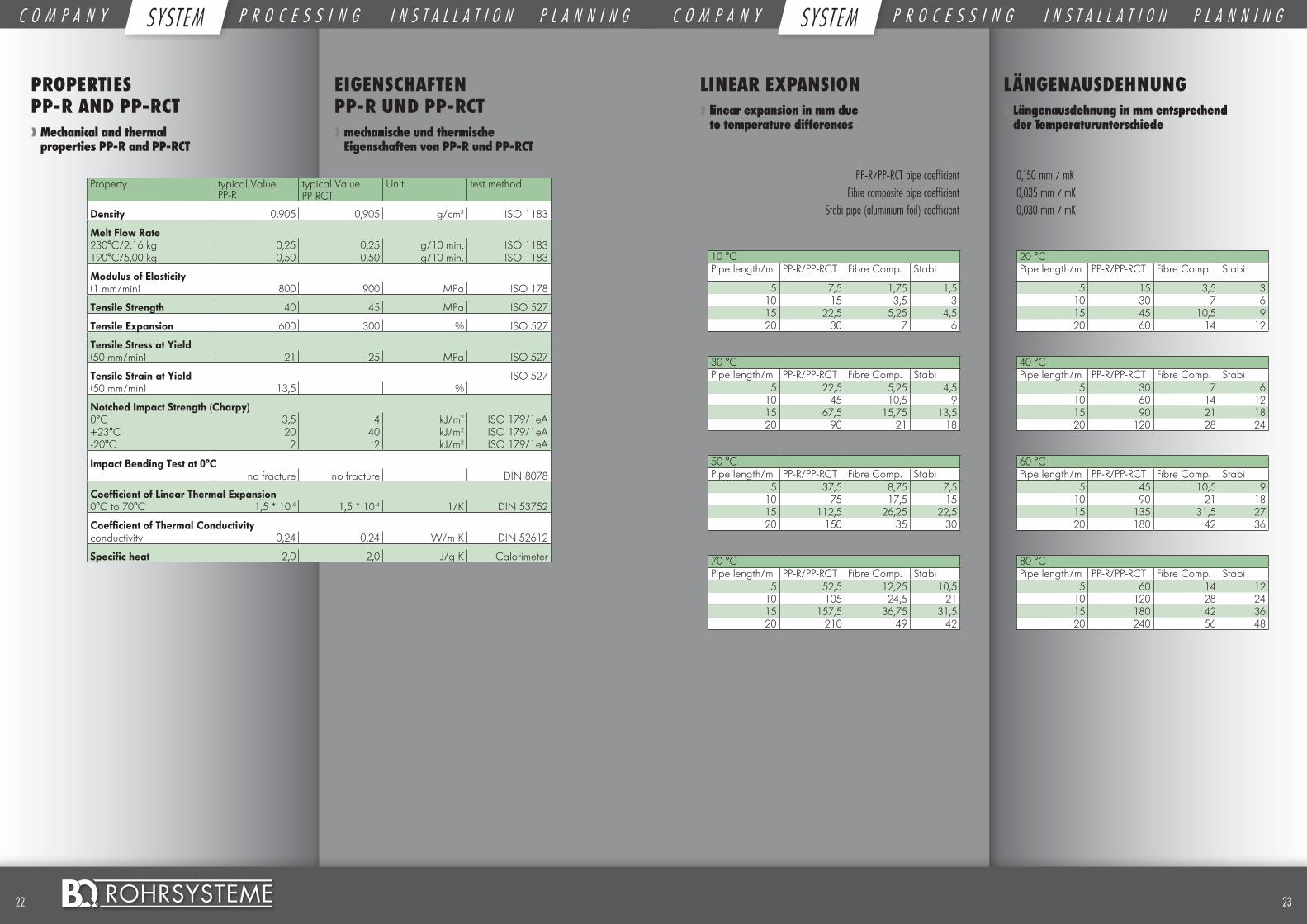
PROPERTIES PP-R AND PP-RCT ❱❱ Mechanical and thermal properties PP-R and PP-RCT
EIGENSCHAFTEN PP-R UND PP-RCT❱❱ mechanische und thermische Eigenschaften von PP-R und PP-RCT
Property typical Value PP-R
typical Value PP-RCT
Unit test method
Density 0,905 0,905 g/cm3 ISO 1183
Melt Flow Rate 230°C/2,16 kg 0,25 0,25 g/10 min. ISO 1183190°C/5,00 kg 0,50 0,50 g/10 min. ISO 1183
Modulus of Elasticity (1 mm/min) 800 900 MPa ISO 178
Tensile Strength 40 45 MPa ISO 527
Tensile Expansion 600 300 % ISO 527
Tensile Stress at Yield (50 mm/min) 21 25 MPa ISO 527
Tensile Strain at Yield ISO 527(50 mm/min) 13,5 %
Notched Impact Strength (Charpy) 0°C 3,5 4 kJ/m2 ISO 179/1eA+23°C 20 40 kJ/m2 ISO 179/1eA-20°C 2 2 kJ/m2 ISO 179/1eA
Impact Bending Test at 0°Cno fracture no fracture DIN 8078
Coefficient of Linear Thermal Expansion 0°C to 70°C 1,5 * 10-4 1,5 * 10-4 1/K DIN 53752
Coefficient of Thermal Conductivity conductivity 0,24 0,24 W/m K DIN 52612
Specific heat 2,0 2,0 J/g K Calorimeter
LINEAR EXPANSION❱❱ linear expansion in mm due to temperature differences
LÄNGENAUSDEHNUNG❱❱ Längenausdehnung in mm entsprechend der Temperaturunterschiede
PP-R/PP-RCT pipe coefficient 0,150 mm / mK Fibre composite pipe coefficient 0,035 mm / mK Stabi pipe (aluminium foil) coefficient 0,030 mm / mK
10 °C 20 °CPipe length/m PP-R/PP-RCT Fibre Comp. Stabi Pipe length/m PP-R/PP-RCT Fibre Comp. Stabi
5 7,5 1,75 1,5 5 15 3,5 310 15 3,5 3 10 30 7 615 22,5 5,25 4,5 15 45 10,5 920 30 7 6 20 60 14 12
30 °C 40 °CPipe length/m PP-R/PP-RCT Fibre Comp. Stabi Pipe length/m PP-R/PP-RCT Fibre Comp. Stabi
5 22,5 5,25 4,5 5 30 7 610 45 10,5 9 10 60 14 1215 67,5 15,75 13,5 15 90 21 1820 90 21 18 20 120 28 24
50 °C 60 °CPipe length/m PP-R/PP-RCT Fibre Comp. Stabi Pipe length/m PP-R/PP-RCT Fibre Comp. Stabi
5 37,5 8,75 7,5 5 45 10,5 910 75 17,5 15 10 90 21 1815 112,5 26,25 22,5 15 135 31,5 2720 150 35 30 20 180 42 36
70 °C 80 °CPipe length/m PP-R/PP-RCT Fibre Comp. Stabi Pipe length/m PP-R/PP-RCT Fibre Comp. Stabi
5 52,5 12,25 10,5 5 60 14 1210 105 24,5 21 10 120 28 2415 157,5 36,75 31,5 15 180 42 3620 210 49 42 20 240 56 48
C O M P A N Y S Y S T E M P R O C E S S I N G I N S T A L L A T I O N P L A N N I N G C O M P A N Y S Y S T E M P R O C E S S I N G I N S T A L L A T I O N P L A N N I N GSYST EM SYST EM
2524 ©
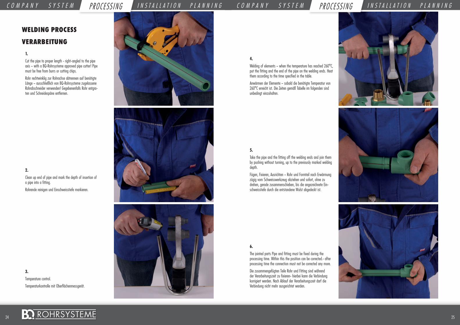
WELDING PROCESS
VERARBEITUNG
3.
Temperature control.
Temperaturkontrolle mit Oberflächenmessgerät.
6.
The jointed parts Pipe and fitting must be fixed during the processing time. Within this the position can be corrected.- after processing time the connection must not be corrected any more.
Die zusammengefügten Teile Rohr und Fitting sind während der Verarbeitungszeit zu fixieren- hierbei kann die Verbindung korrigiert werden. Nach Ablauf der Verarbeitungszeit darf die Verbindung nicht mehr ausgerichtet werden.
2.
Clean up end of pipe and mark the depth of insertion of a pipe into a fitting.
Rohrende reinigen und Einschweisstiefe markieren.
5.
Take the pipe and the fitting off the welding ends and join them by pushing without turning, up to the previously marked welding depth.
Fügen, Fixieren, Ausrichten – Rohr und Formteil nach Erwärmung zügig vom Schweisswerkzeug abziehen und sofort, ohne zu drehen, gerade zusammenschieben, bis die angezeichnete Ein-schweisstiefe durch die entstandene Wulst abgedeckt ist.
1.
Cut the pipe to proper length - right-angled to the pipe axis – with a BQ-Rohrsysteme approved pipe cutter! Pipe must be free from burrs or cutting chips.
Rohr rechtwinklig zur Rohrachse abtrennen auf benötigte Länge – ausschließlich von BQ-Rohrsysteme zugelassene Rohrabschneider verwenden! Gegebenenfalls Rohr entgra-ten und Schneidespäne entfernen.
4.
Welding of elements – when the temperature has reached 260°C, put the fitting and the end of the pipe on the welding ends. Heat them according to the time specified in the table.
Anwärmen der Elemente – sobald die benötigte Temperatur von 260°C erreicht ist. Die Zeiten gemäß Tabelle im folgenden sind unbedingt einzuhalten.
C O M P A N Y S Y S T E M P R O C E S S I N G I N S T A L L A T I O N P L A N N I N G C O M P A N Y S Y S T E M P R O C E S S I N G I N S T A L L A T I O N P L A N N I N GP ROC ESS I NG PROC ESS I NG
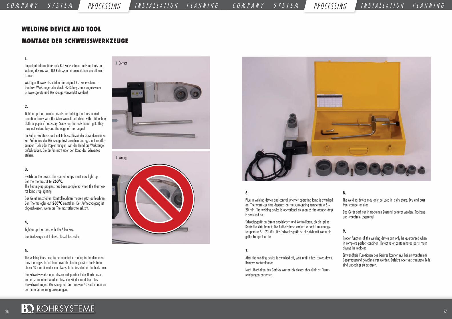
1.
Important information: only BQ-Rohrsysteme tools or tools and welding devices with BQ-Rohrsysteme accreditation are allowed to use!
Wichtiger Hinweis: Es dürfen nur original BQ-Rohrsysteme - Geräte/- Werkzeuge oder durch BQ-Rohrsysteme zugelassene Schweissgeräte und Werkzeuge verwendet werden!
2.
Tighten up the threaded inserts for holding the tools in cold condition firmly with the Allen wrench and clean with a fibre-free cloth or paper if necessary. Screw on the tools hand tight. They may not extend beyond the edge of the tongue!
Im kalten Gerätezustand mit Imbusschlüssel die Gewindeeinsätze zur Aufnahme der Werkzeuge fest anziehen und ggf. mit nichtfa-sernden Tuch oder Papier reinigen. Mit der Hand die Werkzeuge aufschrauben. Sie dürfen nicht über den Rand des Schwertes stehen.
3.
Switch on the device. The control lamps must now light up. Set the thermostat to 260°C. The heating-up progress has been completed when the thermos-tat lamp stop lighting.
Das Gerät einschalten. Kontrollleuchten müssen jetzt aufleuchten. Den Thermoregler auf 260°C einstellen. Der Aufheizvorgang ist abgeschlossen, wenn die Thermostatleuchte erlischt.
4.
Tighten up the tools with the Allen key.
Die Werkzeuge mit Imbusschlüssel festziehen.
5.
The welding tools have to be mounted according to the diameters thus the edges do not loom over the heating device. Tools from above 40 mm diameter are always to be installed at the back hole.
Die Schweisswerkzeuge müssen entsprechend der Durchmesser immer so montiert werden, dass die Ränder nicht über das Heizschwert ragen. Werkzeuge ab Durchmesser 40 sind immer an der hinteren Bohrung anzubringen.
❱❱ Correct
❱❱ Wrong
WELDING DEVICE AND TOOL
MONTAGE DER SCHWEISSWERKZEUGE
6.
Plug in welding device and control whether operating lamp is switched on. The warm-up time depends on the surrounding temperature 5 – 20 min. The welding device is operational as soon as the orange lamp is switched on.
Schweissgerät an Strom anschließen und kontrollieren, ob die grüne Kontrollleuchte brennt. Die Aufheizphase variiert je nach Umgebungs-temperatur 5 – 20 Min. Das Schweissgerät ist einsatzbereit wenn die gelbe Lampe leuchtet.
7.
After the welding device is switched off, wait until it has cooled down. Remove contamination.
Nach Abschalten des Gerätes warten bis dieses abgekühlt ist. Verun-reinigungen entfernen.
8.
The welding device may only be used in a dry state. Dry and dust free storage required!
Das Gerät darf nur in trockenen Zustand genutzt werden. Trockene und staubfreie Lagerung!
9.
Proper function of the welding device can only be guaranteed when in complete perfect condition. Defective or contaminated parts must always be replaced.
Einwandfreie Funktionen des Gerätes können nur bei einwandfreiem Gesamtzustand gewährleistet werden. Defekte oder verschmutzte Teile sind unbedingt zu ersetzen.
2726 ©
C O M P A N Y S Y S T E M P R O C E S S I N G I N S T A L L A T I O N P L A N N I N G C O M P A N Y S Y S T E M P R O C E S S I N G I N S T A L L A T I O N P L A N N I N GP ROC ESS I NG PROC ESS I NG
2928 ©
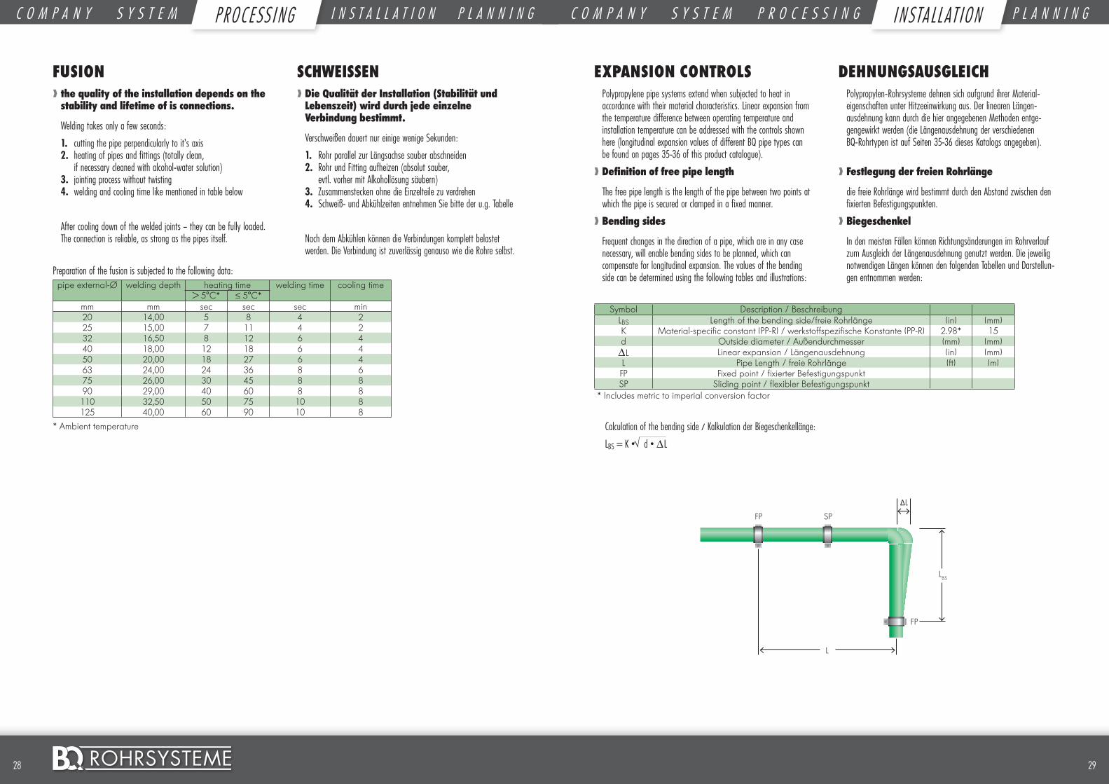
FUSION❱❱ the quality of the installation depends on the stability and lifetime of is connections.
Welding takes only a few seconds:
1. cutting the pipe perpendicularly to it’s axis 2. heating of pipes and fittings (totally clean,
if necessary cleaned with alcohol-water solution)3. jointing process without twisting4. welding and cooling time like mentioned in table below
After cooling down of the welded joints – they can be fully loaded. The connection is reliable, as strong as the pipes itself.
Preparation of the fusion is subjected to the following data: pipe external-Ø welding depth heating time welding time cooling time
> 5°C* ≤ 5°C*mm mm sec sec sec min20 14,00 5 8 4 225 15,00 7 11 4 232 16,50 8 12 6 440 18,00 12 18 6 450 20,00 18 27 6 463 24,00 24 36 8 675 26,00 30 45 8 890 29,00 40 60 8 8110 32,50 50 75 10 8125 40,00 60 90 10 8
* Ambient temperature
SCHWEISSEN❱❱ Die Qualität der Installation (Stabilität und Lebenszeit) wird durch jede einzelne Verbindung bestimmt.
Verschweißen dauert nur einige wenige Sekunden:
1. Rohr parallel zur Längsachse sauber abschneiden 2. Rohr und Fitting aufheizen (absolut sauber,
evtl. vorher mit Alkohollösung säubern)3. Zusammenstecken ohne die Einzelteile zu verdrehen4. Schweiß- und Abkühlzeiten entnehmen Sie bitte der u.g. Tabelle
Nach dem Abkühlen können die Verbindungen komplett belastet werden. Die Verbindung ist zuverlässig genauso wie die Rohre selbst.
EXPANSION CONTROLS Polypropylene pipe systems extend when subjected to heat in accordance with their material characteristics. Linear expansion from the temperature difference between operating temperature and installation temperature can be addressed with the controls shown here (longitudinal expansion values of different BQ pipe types can be found on pages 35-36 of this product catalogue).
❱❱ Definition of free pipe length
The free pipe length is the length of the pipe between two points at which the pipe is secured or clamped in a fixed manner.
❱❱ Bending sides
Frequent changes in the direction of a pipe, which are in any case necessary, will enable bending sides to be planned, which can compensate for longitudinal expansion. The values of the bending side can be determined using the following tables and illustrations:
Symbol Description / Beschreibung
LBS Length of the bending side/freie Rohrlänge (in) (mm)K Material-specific constant (PP-R) / werkstoffspezifische Konstante (PP-R) 2.98* 15d Outside diameter / Außendurchmesser (mm) (mm)∆L Linear expansion / Längenausdehnung (in) (mm)L Pipe Length / freie Rohrlänge (ft) (m)FP Fixed point / fixierter BefestigungspunktSP Sliding point / flexibler Befestigungspunkt
* Includes metric to imperial conversion factor
Calculation of the bending side / Kalkulation der Biegeschenkellänge:
LBS = K • d • ∆L
DEHNUNGSAUSGLEICHPolypropylen-Rohrsysteme dehnen sich aufgrund ihrer Material-eigenschaften unter Hitzeeinwirkung aus. Der linearen Längen-ausdehnung kann durch die hier angegebenen Methoden entge-gengewirkt werden (die Längenausdehnung der verschiedenen BQ-Rohrtypen ist auf Seiten 35-36 dieses Katalogs angegeben).
❱❱ Festlegung der freien Rohrlänge
die freie Rohrlänge wird bestimmt durch den Abstand zwischen den fixierten Befestigungspunkten.
❱❱ Biegeschenkel
In den meisten Fällen können Richtungsänderungen im Rohrverlauf zum Ausgleich der Längenausdehnung genutzt werden. Die jeweilig notwendigen Längen können den folgenden Tabellen und Darstellun-gen entnommen werden:
∆L
LBS
SP
FP
L
FP
C O M P A N Y S Y S T E M P R O C E S S I N G I N S T A L L A T I O N P L A N N I N G C O M P A N Y S Y S T E M P R O C E S S I N G I N S T A L L A T I O N P L A N N I N GI N STA LL AT I ONPROC ESS I NG
Zeichnung folgt.
3130 ©
Durchmesser (mm)
Längenausdehnung ∆L (mm)10 20 30 40 50 60 70 80 90 100 110 120
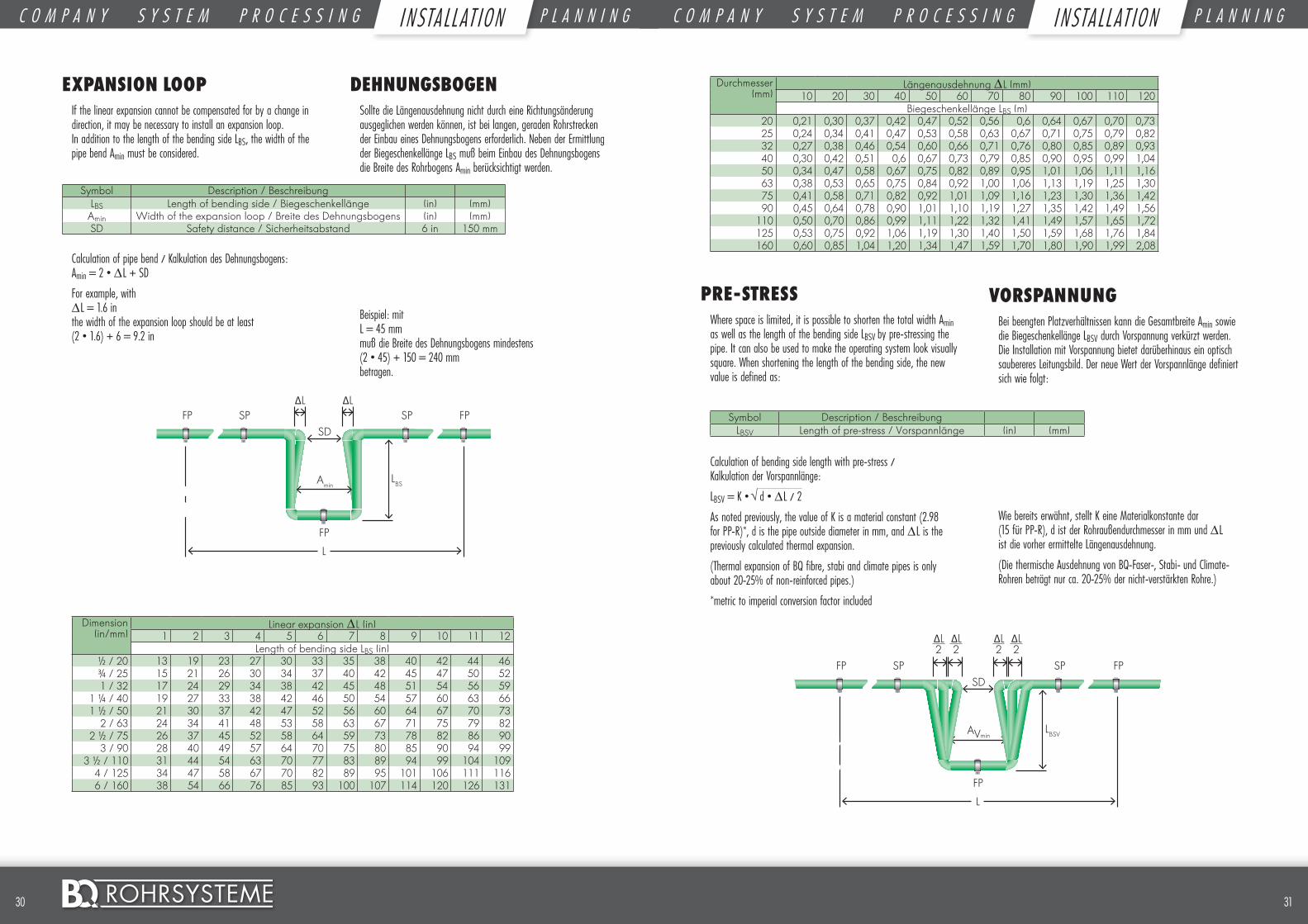
Biegeschenkellänge LBS (m)20 0,21 0,30 0,37 0,42 0,47 0,52 0,56 0,6 0,64 0,67 0,70 0,7325 0,24 0,34 0,41 0,47 0,53 0,58 0,63 0,67 0,71 0,75 0,79 0,8232 0,27 0,38 0,46 0,54 0,60 0,66 0,71 0,76 0,80 0,85 0,89 0,9340 0,30 0,42 0,51 0,6 0,67 0,73 0,79 0,85 0,90 0,95 0,99 1,0450 0,34 0,47 0,58 0,67 0,75 0,82 0,89 0,95 1,01 1,06 1,11 1,1663 0,38 0,53 0,65 0,75 0,84 0,92 1,00 1,06 1,13 1,19 1,25 1,3075 0,41 0,58 0,71 0,82 0,92 1,01 1,09 1,16 1,23 1,30 1,36 1,4290 0,45 0,64 0,78 0,90 1,01 1,10 1,19 1,27 1,35 1,42 1,49 1,56
110 0,50 0,70 0,86 0,99 1,11 1,22 1,32 1,41 1,49 1,57 1,65 1,72125 0,53 0,75 0,92 1,06 1,19 1,30 1,40 1,50 1,59 1,68 1,76 1,84160 0,60 0,85 1,04 1,20 1,34 1,47 1,59 1,70 1,80 1,90 1,99 2,08
PRE-STRESS Where space is limited, it is possible to shorten the total width Amin as well as the length of the bending side LBSV by pre-stressing the pipe. It can also be used to make the operating system look visually square. When shortening the length of the bending side, the new value is defined as:
Symbol Description / BeschreibungLBSV Length of pre-stress / Vorspannlänge (in) (mm)
Calculation of bending side length with pre-stress / Kalkulation der Vorspannlänge:
LBSV = K • d • ∆L / 2
As noted previously, the value of K is a material constant (2.98 for PP-R)*, d is the pipe outside diameter in mm, and ∆L is the previously calculated thermal expansion.
(Thermal expansion of BQ fibre, stabi and climate pipes is only about 20-25% of non-reinforced pipes.)
*metric to imperial conversion factor included
VORSPANNUNGBei beengten Platzverhältnissen kann die Gesamtbreite Amin sowie die Biegeschenkellänge LBSV durch Vorspannung verkürzt werden. Die Installation mit Vorspannung bietet darüberhinaus ein optisch saubereres Leitungsbild. Der neue Wert der Vorspannlänge definiert sich wie folgt:
Wie bereits erwähnt, stellt K eine Materialkonstante dar (15 für PP-R), d ist der Rohraußendurchmesser in mm und ∆L ist die vorher ermittelte Längenausdehnung.
(Die thermische Ausdehnung von BQ-Faser-, Stabi- und Climate-Rohren beträgt nur ca. 20-25% der nicht-verstärkten Rohre.)
EXPANSION LOOP If the linear expansion cannot be compensated for by a change in direction, it may be necessary to install an expansion loop. In addition to the length of the bending side LBS, the width of the pipe bend Amin must be considered.
Symbol Description / Beschreibung
LBS Length of bending side / Biegeschenkellänge (in) (mm)Amin Width of the expansion loop / Breite des Dehnungsbogens (in) (mm)SD Safety distance / Sicherheitsabstand 6 in 150 mm
Calculation of pipe bend / Kalkulation des Dehnungsbogens: Amin = 2 • ∆L + SD
For example, with ∆L = 1.6 in the width of the expansion loop should be at least (2 • 1.6) + 6 = 9.2 in
Dimension (in/mm)
Linear expansion ∆L (in)1 2 3 4 5 6 7 8 9 10 11 12
Length of bending side LBS (in)½ / 20 13 19 23 27 30 33 35 38 40 42 44 46¾ / 25 15 21 26 30 34 37 40 42 45 47 50 521 / 32 17 24 29 34 38 42 45 48 51 54 56 59
1 ¼ / 40 19 27 33 38 42 46 50 54 57 60 63 661 ½ / 50 21 30 37 42 47 52 56 60 64 67 70 73
2 / 63 24 34 41 48 53 58 63 67 71 75 79 822 ½ / 75 26 37 45 52 58 64 59 73 78 82 86 90
3 / 90 28 40 49 57 64 70 75 80 85 90 94 993 ½ / 110 31 44 54 63 70 77 83 89 94 99 104 109
4 / 125 34 47 58 67 70 82 89 95 101 106 111 1166 / 160 38 54 66 76 85 93 100 107 114 120 126 131
DEHNUNGSBOGENSollte die Längenausdehnung nicht durch eine Richtungsänderung ausgeglichen werden können, ist bei langen, geraden Rohrstrecken der Einbau eines Dehnungsbogens erforderlich. Neben der Ermittlung der Biegeschenkellänge LBS muß beim Einbau des Dehnungsbogens die Breite des Rohrbogens Amin berücksichtigt werden.
Beispiel: mit L = 45 mm muß die Breite des Dehnungsbogens mindestens (2 • 45) + 150 = 240 mm betragen.
L
∆L∆L
LBSAmin
SP SP
FP
SDFP FP
L
LBSV
SP SP
FP
SDFP FP
∆L2
∆L2
∆L2
∆L2
AVmin
C O M P A N Y S Y S T E M P R O C E S S I N G I N S T A L L A T I O N P L A N N I N G C O M P A N Y S Y S T E M P R O C E S S I N G I N S T A L L A T I O N P L A N N I N GI N STA LL AT I ON I NSTA LL AT I ON
Zeichnung folgt.
Zeichnung folgt.
3332 ©
Dimension (in/mm)
Linear expansion ∆L (in)1 2 3 4 5 6 7 8 9 10 11 12
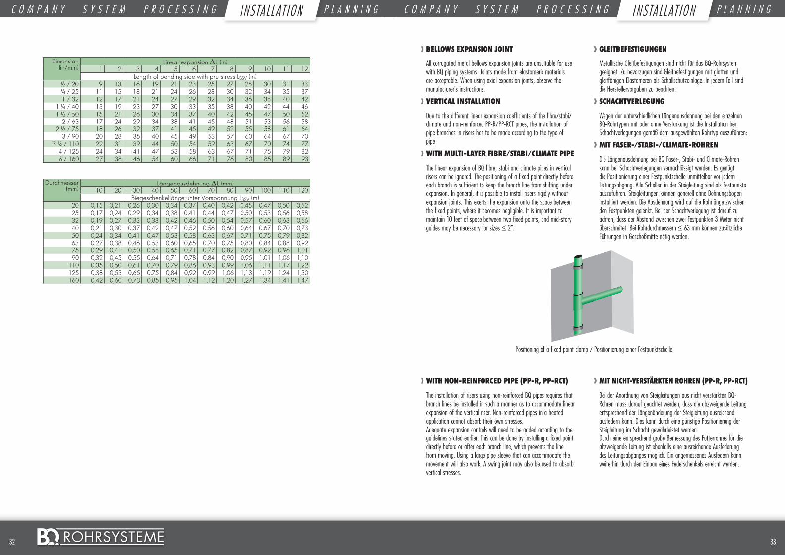
Length of bending side with pre-stress LBSV (in)½ / 20 9 13 16 19 21 23 25 27 28 30 31 33¾ / 25 11 15 18 21 24 26 28 30 32 34 35 371 / 32 12 17 21 24 27 29 32 34 36 38 40 42
1 ¼ / 40 13 19 23 27 30 33 35 38 40 42 44 461 ½ / 50 15 21 26 30 34 37 40 42 45 47 50 52
2 / 63 17 24 29 34 38 41 45 48 51 53 56 582 ½ / 75 18 26 32 37 41 45 49 52 55 58 61 64
3 / 90 20 28 35 40 45 49 53 57 60 64 67 703 ½ / 110 22 31 39 44 50 54 59 63 67 70 74 77
4 / 125 24 34 41 47 53 58 63 67 71 75 79 826 / 160 27 38 46 54 60 66 71 76 80 85 89 93
Durchmesser (mm)
Längenausdehnung ∆L (mm)10 20 30 40 50 60 70 80 90 100 110 120
Biegeschenkellänge unter Vorspannung LBSV (m)20 0,15 0,21 0,26 0,30 0,34 0,37 0,40 0,42 0,45 0,47 0,50 0,5225 0,17 0,24 0,29 0,34 0,38 0,41 0,44 0,47 0,50 0,53 0,56 0,5832 0,19 0,27 0,33 0,38 0,42 0,46 0,50 0,54 0,57 0,60 0,63 0,6640 0,21 0,30 0,37 0,42 0,47 0,52 0,56 0,60 0,64 0,67 0,70 0,7350 0,24 0,34 0,41 0,47 0,53 0,58 0,63 0,67 0,71 0,75 0,79 0,8263 0,27 0,38 0,46 0,53 0,60 0,65 0,70 0,75 0,80 0,84 0,88 0,9275 0,29 0,41 0,50 0,58 0,65 0,71 0,77 0,82 0,87 0,92 0,96 1,0190 0,32 0,45 0,55 0,64 0,71 0,78 0,84 0,90 0,95 1,01 1,06 1,10
110 0,35 0,50 0,61 0,70 0,79 0,86 0,93 0,99 1,06 1,11 1,17 1,22125 0,38 0,53 0,65 0,75 0,84 0,92 0,99 1,06 1,13 1,19 1,24 1,30160 0,42 0,60 0,73 0,85 0,95 1,04 1,12 1,20 1,27 1,34 1,41 1,47
❱❱ BELLOWS EXPANSION JOINT
All corrugated metal bellows expansion joints are unsuitable for use with BQ piping systems. Joints made from elastomeric materials are acceptable. When using axial expansion joints, observe the manufacturer’s instructions.
❱❱ VERTICAL INSTALLATION
Due to the different linear expansion coefficients of the fibre/stabi/climate and non-reinforced PP-R/PP-RCT pipes, the installation of pipe branches in risers has to be made according to the type of pipe:
❱❱ WITH MULTI-LAYER FIBRE/STABI/CLIMATE PIPE
The linear expansion of BQ fibre, stabi and climate pipes in vertical risers can be ignored. The positioning of a fixed point directly before each branch is sufficient to keep the branch line from shifting under expansion. In general, it is possible to install risers rigidly without expansion joints. This exerts the expansion onto the space between the fixed points, where it becomes negligible. It is important to maintain 10 feet of space between two fixed points, and mid-story guides may be necessary for sizes ≤ 2”.
❱❱ WITH NON-REINFORCED PIPE (PP-R, PP-RCT)
The installation of risers using non-reinforced BQ pipes requires that branch lines be installed in such a manner as to accommodate linear expansion of the vertical riser. Non-reinforced pipes in a heated application cannot absorb their own stresses. Adequate expansion controls will need to be added according to the guidelines stated earlier. This can be done by installing a fixed point directly before or after each branch line, which prevents the line from moving. Using a large pipe sleeve that can accommodate the movement will also work. A swing joint may also be used to absorb vertical stresses.
❱❱ GLEITBEFESTIGUNGEN
Metallische Gleitbefestigungen sind nicht für das BQ-Rohrsystem geeignet. Zu bevorzugen sind Gleitbefestigungen mit glatten und gleitfähigen Elastomeren als Schallschutzeinlage. In jedem Fall sind die Herstellervorgaben zu beachten.
❱❱ SCHACHTVERLEGUNG
Wegen der unterschiedlichen Längenausdehnung bei den einzelnen BQ-Rohrtypen mit oder ohne Verstärkung ist die Installation bei Schachtverlegungen gemäß dem ausgewählten Rohrtyp auszuführen:
❱❱ MIT FASER-/STABI-/CLIMATE-ROHREN
Die Längenausdehnung bei BQ Faser-, Stabi- und Climate-Rohren kann bei Schachtverlegungen vernachlässigt werden. Es genügt die Positionierung einer Festpunktschelle unmittelbar vor jedem Leitungsabgang. Alle Schellen in der Steigleitung sind als Festpunkte auszuführen. Steigleitungen können generell ohne Dehnungsbögen installiert werden. Die Ausdehnung wird auf die Rohrlänge zwischen den Festpunkten gelenkt. Bei der Schachtverlegung ist darauf zu achten, dass der Abstand zwischen zwei Festpunkten 3 Meter nicht überschreitet. Bei Rohrdurchmessern ≤ 63 mm können zusätzliche Führungen in Geschoßmitte nötig werden.
❱❱ MIT NICHT-VERSTÄRKTEN ROHREN (PP-R, PP-RCT)
Bei der Anordnung von Steigleitungen aus nicht verstärkten BQ-Rohren muss darauf geachtet werden, dass die abzweigende Leitung entsprechend der Längenänderung der Steigleitung ausreichend ausfedern kann. Dies kann durch eine günstige Positionierung der Steigleitung im Schacht gewährleistet werden. Durch eine entsprechend große Bemessung des Futterrohres für die abzweigende Leitung ist ebenfalls eine ausreichende Ausfederung des Leitungsabganges möglich. Ein angemessenes Ausfedern kann weiterhin durch den Einbau eines Federschenkels erreicht werden.
Positioning of a fixed point clamp / Positionierung einer Festpunktschelle
C O M P A N Y S Y S T E M P R O C E S S I N G I N S T A L L A T I O N P L A N N I N G C O M P A N Y S Y S T E M P R O C E S S I N G I N S T A L L A T I O N P L A N N I N GI N STA LL AT I ON I NSTA LL AT I ON
Zeichnung folgt.
3534 ©
1. Dirty and untidy workplaces increase the chances of accidents
Unsaubere und nicht aufgeräumte Arbeitsplätze erhöhen das Unfallrisiko
2. Machines and devices are to be stored under dry conditions and secured against unauthorized access.
Maschinen und Zubehör sind trocken zu lagern und gegen Zugriff von Nichtbefugten zu schützen.
3. Ensure that pipe and fitting are always located firmly in the clamping devices. Caution by closing the clamps – hazard of crush of worse injury to hands.
Stellen Sie sicher das Rohr und Fitting immer sicher in der Befestigung sind. Vorsicht bei Feststellen der Klammern. Es drohen Quetschungen der Hände.
4. Caution of burning! The metal parts on the heating elements will have temperatures up to 300°C - please make sure that nobody touches them. Inflammable parts must be kept away.
Vorsicht Verbrennungsgefahr! Die Metallteile am Heizelement der Schweissmaschine können Temperaturen bis zu 300°C aufweisen. Stellen Sie sicher dass diese niemals berührt werden. Brennbare Teile müssen in sicherer Entfernung gelagert werden.
5. Damaged parts must be replaced immediately.
Beschädigte Teile müssen sofort ersetzt werden.
6. Use only BQ-Rohrsysteme approved spare parts.
Benutzen Sie nur von BQ-Rohrsysteme zugelassene Ersatzteile.
HEALTH AND SAFETY REGULATIONS ❱❱ There is always a certain risk of injury when operating with plastic pipe welding machines. Observation of the following accident pre-vention regulations reduces this danger to a minimum. Non –Observation of them can lead to accidents!
ARBEITSSCHUTZ- BESTIMMUNGEN
❱❱ Es besteht immer Verletzungsgefahr bei der Handhabung von Kunststoff-Rohr Schweiss-maschinen. Die Beachtung der nachfolgenden Sicherheitshinweise reduziert dieses Risiko bis auf ein Minimum. Nichtbeachtung kann zu Unfällen führen.
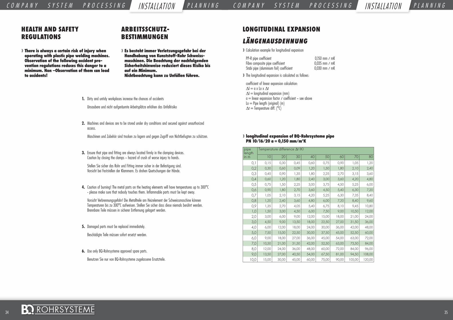
❱❱ longitudinal expansion of BQ-Rohrsysteme pipe PN 10/16/20 a = 0,150 mm/m*K
pipe length
Temperature difference ∆t (K)
in m 10 20 30 40 50 60 70 80
0,1 0,15 0,30 0,45 0,60 0,75 0,90 1,05 1,20
0,2 0,30 0,60 0,09 1,20 1,50 1,80 2,10 2,40
0,3 0,45 0,90 1,35 1,80 2,25 2,70 3,15 3,60
0,4 0,60 1,20 1,80 2,40 3,00 3,60 4,20 4,80
0,5 0,75 1,50 2,25 3,00 3,75 4,50 5,25 6,00
0,6 0,90 1,80 2,70 3,60 4,50 5,40 6,30 7,20
0,7 1,05 2,10 3,15 4,20 5,25 6,30 7,35 8,40
0,8 1,20 2,40 3,60 4,80 6,00 7,20 8,40 9,60
0,9 1,35 2,70 4,05 5,40 6,75 8,10 9,45 10,80
1,0 1,50 3,00 4,50 6,00 7,50 9,00 10,50 12,00
2,0 3,00 6,00 9,00 12,00 15,00 18,00 21,00 24,00
3,0 4,50 9,00 13,50 18,00 22,50 27,00 31,50 36,00
4,0 6,00 12,00 18,00 24,00 30,00 36,00 42,00 48,00
5,0 7,50 15,00 22,50 30,00 37,50 45,00 52,50 60,00
6,0 9,00 18,00 27,00 36,00 45,00 54,00 63,00 72,00
7,0 10,50 21,00 31,50 42,00 52,50 63,00 73,50 84,00
8,0 12,00 24,00 36,00 48,00 60,00 72,00 84,00 96,00
9,0 13,50 27,00 40,50 54,00 67,50 81,00 94,50 108,00
10,0 15,00 30,00 45,00 60,00 75,00 90,00 105,00 120,00
LONGITUDINAL EXPANSION
LÄNGENAUSDEHNUNG❱❱ Calculation example for longitudinal expanison
PP-R pipe coefficient 0,150 mm / mK Fibre composite pipe coefficient 0,035 mm / mK Stabi pipe (aluminium foil) coefficient 0,030 mm / mK
❱❱ The longitudinal expansion is calculated as follows:
coefficient of linear expansion calculation: ∆I = a x Lo x ∆t ∆I = longitudinal expansion (mm) a = linear expansion factor / coefficient – see above Lo = Pipe length (original) (m) ∆t = Temperature diff. (°C)
C O M P A N Y S Y S T E M P R O C E S S I N G I N S T A L L A T I O N P L A N N I N G C O M P A N Y S Y S T E M P R O C E S S I N G I N S T A L L A T I O N P L A N N I N GI N STA LL AT I ON I NSTA LL AT I ON
3736 ©
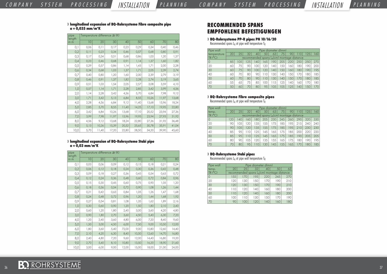
❱❱ longitudinal expansion of BQ-Rohrsysteme Fibre composite pipe a = 0,035 mm/m*K
pipe length
Temperature difference ∆t (K)
in m 10 20 30 40 50 60 70 80
0,1 0,06 0,11 0,17 0,23 0,29 0,34 0,40 0,46
0,2 0,11 0,23 0,34 0,46 0,57 0,68 0,80 0,91
0,3 0,17 0,34 0,51 0,68 0,86 1,03 1,20 1,37
0,4 0,23 0,46 0,68 0,91 1,14 1,37 1,60 1,82
0,5 0,29 0,57 0,86 1,14 1,43 1,71 2,00 2,28
0,6 0,34 0,68 1,03 1,37 1,71 2,05 2,39 2,74
0,7 0,40 0,80 1,20 1,60 2,00 2,39 2,79 3,19
0,8 0,46 0,91 1,37 1,82 2,28 2,74 3,19 3,65
0,9 0,51 1,03 1,54 2,05 2,57 3,08 3,59 4,10
1,0 0,57 1,14 1,71 2,28 2,85 3,42 3,99 4,56
2,0 1,14 2,28 3,42 4,56 5,70 6,84 7,98 9,12
3,0 1,71 3,42 5,13 6,84 8,55 10,26 11,97 13,68
4,0 2,28 4,56 6,84 9,12 11,40 13,68 15,96 18,24
5,0 2,85 5,70 8,55 11,40 14,25 17,10 19,95 22,80
6,0 3,42 6,84 10,26 13,68 17,10 20,52 23,94 27,36
7,0 3,99 7,98 11,97 15,96 19,95 23,94 27,93 31,92
8,0 4,56 9,12 13,68 18,24 22,80 27,36 31,92 36,48
9,0 5,13 10,26 15,39 20,52 25,65 30,78 35,91 41,04
10,0 5,70 11,40 17,20 22,80 28,50 34,20 39,90 45,60
❱❱ longitudinal expansion of BQ-Rohrsysteme Stabi pipe a = 0,03 mm/m*K
pipe length
Temperature difference ∆t (K)
in m 10 20 30 40 50 60 70 80
0,1 0,03 0,06 0,09 0,12 0,15 0,18 0,21 0,24
0,2 0,06 0,12 0,18 0,24 0,30 0,36 0,42 0,48
0,3 0,09 0,18 0,27 0,36 0,45 0,54 0,63 0,72
0,4 0,12 0,24 0,36 0,48 0,60 0,72 0,84 0,96
0,5 0,15 0,30 0,45 0,60 0,75 0,90 1,05 1,20
0,6 0,18 0,36 0,54 0,72 0,90 1,08 1,26 1,44
0,7 0,21 0,42 0,63 0,84 1,05 1,26 1,47 1,68
0,8 0,24 0,48 0,72 0,96 1,20 1,44 1,68 1,92
0,9 0,27 0,54 0,81 1,08 1,35 1,62 1,89 2,16
1,0 0,30 0,60 0,90 1,20 1,50 1,80 2,10 2,40
2,0 0,60 1,20 1,80 2,40 3,00 3,60 4,20 4,80
3,0 0,90 1,80 2,70 3,60 4,50 5,40 6,30 7,20
4,0 1,20 2,40 3,60 4,80 6,00 7,20 8,40 9,60
5,0 1,50 3,00 4,50 6,00 7,50 9,00 10,50 12,00
6,0 1,80 3,60 5,40 72,00 9,00 10,80 12,60 14,40
7,0 2,10 4,20 6,30 8,40 10,50 12,60 14,70 16,80
8,0 2,40 4,80 7,20 9,60 12,00 14,40 16,80 19,20
9,0 2,70 5,40 8,10 10,80 13,50 16,20 18,90 21,60
10,0 3,00 6,00 9,00 12,00 15,00 18,00 21,00 24,00
RECOMMENDED SPANS EMPFOHLENE BEFESTIGUNGEN❱❱ BQ-Rohrsysteme PP-R pipes PN 10/16/20 Recommended spans LA at pipe wall temperature TR
Pipe wall Pipe diameter d(mm)temperature 20 25 32 40 50 63 75 90 110 125 160TR (°C) recommended spans LA(cm) montage distance0 85 105 125 140 165 190 205 220 250 250 27020 60 75 90 100 120 140 150 160 180 190 20030 60 75 90 100 120 140 150 160 180 190 19540 60 70 80 90 110 130 140 150 170 180 18550 60 70 80 90 110 130 140 150 170 180 18560 55 65 75 85 100 115 125 140 160 170 18070 50 60 70 80 95 105 105 125 140 150 170
❱❱ BQ-Rohrsysteme Fibre composite pipes Recommended spans LA at pipe wall temperature TR
Pipe wall Pipe diameter d(mm)temp. 20 25 32 40 50 63 75 90 110 125 160TR (°C) recommended spans LA(cm) montage distance0 120 140 160 180 205 230 245 260 290 320 33020 90 105 120 135 155 175 185 195 215 240 24030 90 105 120 135 155 175 185 195 210 230 23040 85 95 110 125 145 165 175 185 200 220 22050 85 95 110 125 145 165 175 185 190 205 20560 80 90 105 120 135 155 165 175 180 190 19570 70 80 95 110 130 145 155 165 170 180 185
❱❱ BQ-Rohrsysteme Stabi pipes Recommended spans LA at pipe wall temperature TR
Pipe wall Pipe diameter d(mm)temp. 20 25 32 40 50 63TR (°C) recommended spans LA(cm) montage distance0 155 170 195 220 245 27020 120 130 150 170 190 21030 120 130 150 170 190 21040 110 120 140 160 180 20050 110 120 140 160 180 20060 100 110 130 150 170 19070 90 100 120 140 160 180
C O M P A N Y S Y S T E M P R O C E S S I N G I N S T A L L A T I O N P L A N N I N G C O M P A N Y S Y S T E M P R O C E S S I N G I N S T A L L A T I O N P L A N N I N GI N STA LL AT I ON I NSTA LL AT I ON
NOTES NOTIZEN
3938 ©
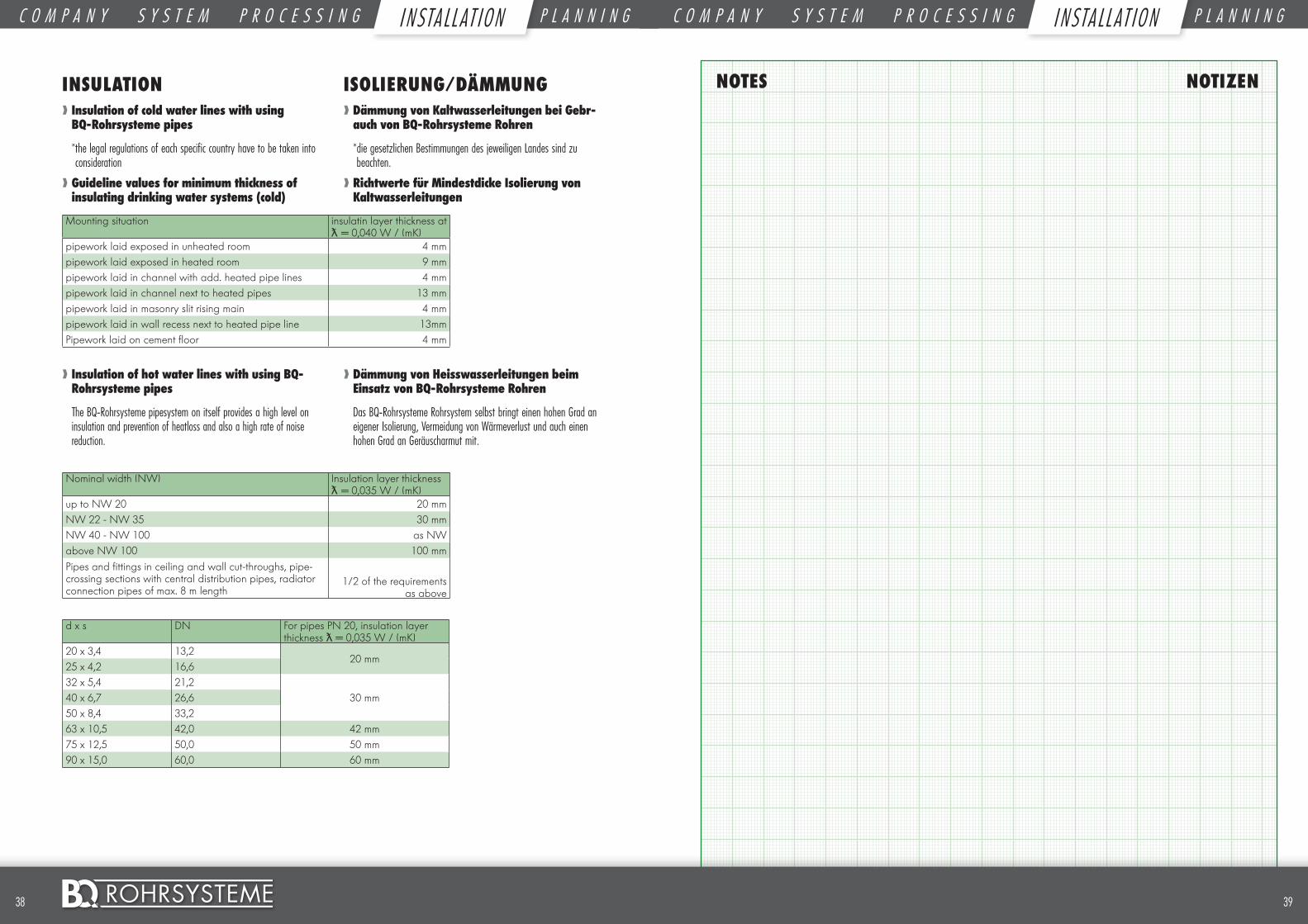
INSULATION❱❱ Insulation of cold water lines with using BQ-Rohrsysteme pipes
* the legal regulations of each specific country have to be taken into consideration
❱❱ Guideline values for minimum thickness of insulating drinking water systems (cold)
Mounting situation insulatin layer thickness at ƛ = 0,040 W / (mK)
pipework laid exposed in unheated room 4 mmpipework laid exposed in heated room 9 mmpipework laid in channel with add. heated pipe lines 4 mmpipework laid in channel next to heated pipes 13 mmpipework laid in masonry slit rising main 4 mmpipework laid in wall recess next to heated pipe line 13mmPipework laid on cement floor 4 mm
❱❱ Insulation of hot water lines with using BQ-Rohrsysteme pipes
The BQ-Rohrsysteme pipesystem on itself provides a high level on insulation and prevention of heatloss and also a high rate of noise reduction.
Nominal width (NW) Insulation layer thickness ƛ = 0,035 W / (mK)
up to NW 20 20 mmNW 22 - NW 35 30 mmNW 40 - NW 100 as NWabove NW 100 100 mmPipes and fittings in ceiling and wall cut-throughs, pipe-crossing sections with central distribution pipes, radiator connection pipes of max. 8 m length
1/2 of the requirements as above
d x s DN For pipes PN 20, insulation layer thickness ƛλ= 0,035 W / (mK)
20 x 3,4 13,220 mm
25 x 4,2 16,632 x 5,4 21,2
30 mm40 x 6,7 26,650 x 8,4 33,263 x 10,5 42,0 42 mm75 x 12,5 50,0 50 mm90 x 15,0 60,0 60 mm
ISOLIERUNG/DÄMMUNG❱❱ Dämmung von Kaltwasserleitungen bei Gebr-auch von BQ-Rohrsysteme Rohren
* die gesetzlichen Bestimmungen des jeweiligen Landes sind zu beachten.
❱❱ Richtwerte für Mindestdicke Isolierung von Kaltwasserleitungen
❱❱ Dämmung von Heisswasserleitungen beim Einsatz von BQ-Rohrsysteme Rohren
Das BQ-Rohrsysteme Rohrsystem selbst bringt einen hohen Grad an eigener Isolierung, Vermeidung von Wärmeverlust und auch einen hohen Grad an Geräuscharmut mit.
C O M P A N Y S Y S T E M P R O C E S S I N G I N S T A L L A T I O N P L A N N I N G C O M P A N Y S Y S T E M P R O C E S S I N G I N S T A L L A T I O N P L A N N I N GI N STA LL AT I ON I NSTA LL AT I ON
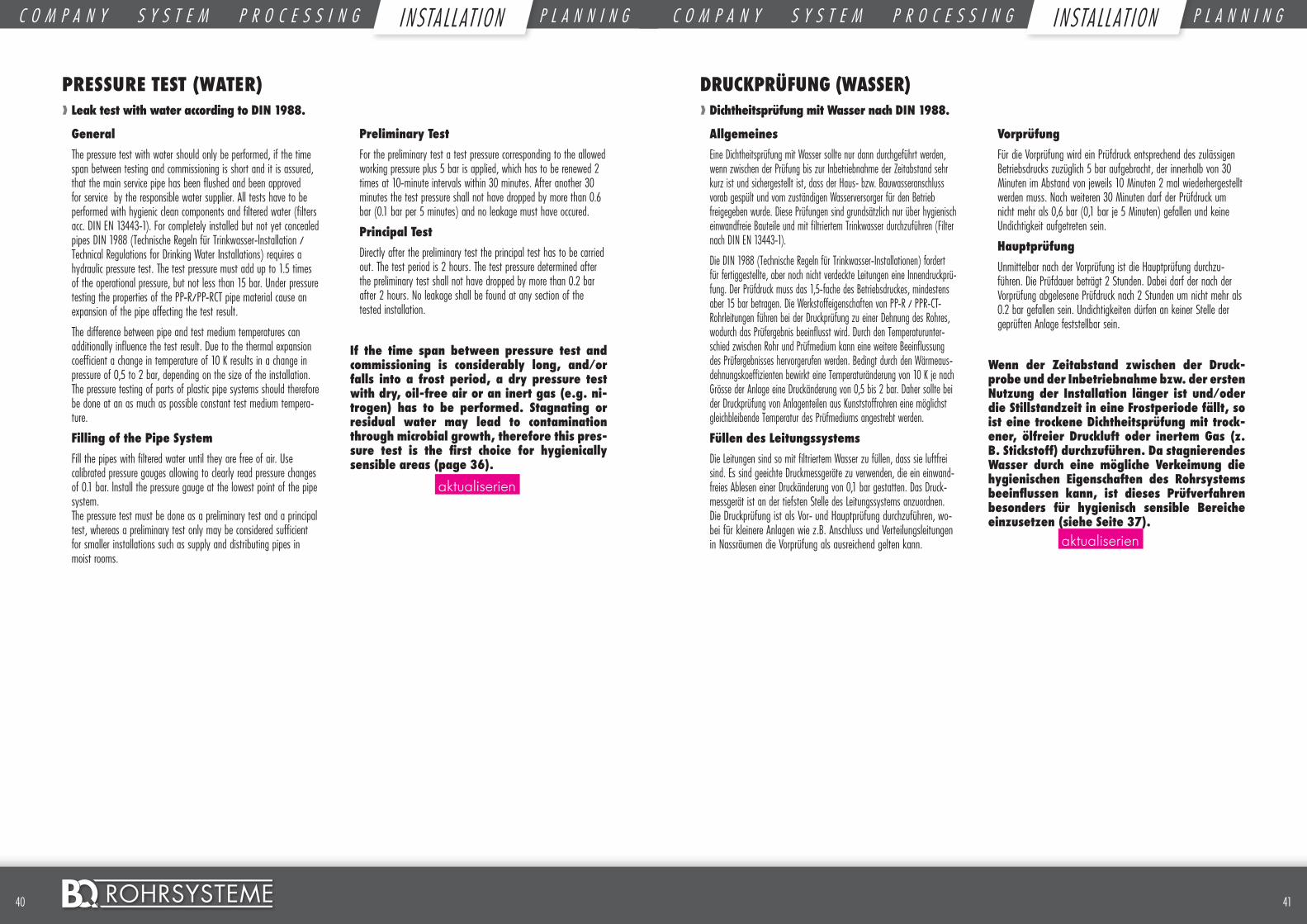
4140 ©
PRESSURE TEST (WATER)❱❱ Leak test with water according to DIN 1988.
General
The pressure test with water should only be performed, if the time span between testing and commissioning is short and it is assured, that the main service pipe has been flushed and been approved for service by the responsible water supplier. All tests have to be performed with hygienic clean components and filtered water (filters acc. DIN EN 13443-1). For completely installed but not yet concealed pipes DIN 1988 (Technische Regeln für Trinkwasser-lnstallation / Technical Regulations for Drinking Water Installations) requires a hydraulic pressure test. The test pressure must add up to 1.5 times of the operational pressure, but not less than 15 bar. Under pressure testing the properties of the PP-R/PP-RCT pipe material cause an expansion of the pipe affecting the test result.
The difference between pipe and test medium temperatures can additionally influence the test result. Due to the thermal expansion coefficient a change in temperature of 10 K results in a change in pressure of 0,5 to 2 bar, depending on the size of the installation. The pressure testing of parts of plastic pipe systems should therefore be done at an as much as possible constant test medium tempera-ture.
Filling of the Pipe System
Fill the pipes with filtered water until they are free of air. Use calibrated pressure gauges allowing to clearly read pressure changes of 0.1 bar. lnstall the pressure gauge at the lowest point of the pipe system. The pressure test must be done as a preliminary test and a principal test, whereas a preliminary test only may be considered sufficient for smaller installations such as supply and distributing pipes in moist rooms.
Preliminary Test
For the preliminary test a test pressure corresponding to the allowed working pressure plus 5 bar is applied, which has to be renewed 2 times at 10-minute intervals within 30 minutes. After another 30 minutes the test pressure shall not have dropped by more than 0.6 bar (0.1 bar per 5 minutes) and no leakage must have occured.
Principal Test
Directly after the preliminary test the principal test has to be carried out. The test period is 2 hours. The test pressure determined after the preliminary test shall not have dropped by more than 0.2 bar after 2 hours. No leakage shall be found at any section of the tested installation.
If the time span between pressure test and commissioning is considerably long, and/or falls into a frost period, a dry pressure test with dry, oil-free air or an inert gas (e.g. ni-trogen) has to be performed. Stagnating or residual water may lead to contamination through microbial growth, therefore this pres-sure test is the first choice for hygienically sensible areas (page 36).
DRUCKPRÜFUNG (WASSER)❱❱ Dichtheitsprüfung mit Wasser nach DIN 1988.
Allgemeines
Eine Dichtheitsprüfung mit Wasser sollte nur dann durchgeführt werden, wenn zwischen der Prüfung bis zur Inbetriebnahme der Zeitabstand sehr kurz ist und sichergestellt ist, dass der Haus- bzw. Bauwasseranschluss vorab gespült und vom zuständigen Wasserversorger für den Betrieb freigegeben wurde. Diese Prüfungen sind grundsätzlich nur über hygienisch einwandfreie Bauteile und mit filtriertem Trinkwasser durchzuführen (Filter nach DIN EN 13443-1).
Die DIN 1988 (Technische Regeln für Trinkwasser-Installationen) fordert für fertiggestellte, aber noch nicht verdeckte Leitungen eine Innendruckprü-fung. Der Prüfdruck muss das 1,5-fache des Betriebsdruckes, mindestens aber 15 bar betragen. Die Werkstoffeigenschaften von PP-R / PPR-CT-Rohrleitungen führen bei der Druckprüfung zu einer Dehnung des Rohres, wodurch das Prüfergebnis beeinflusst wird. Durch den Temperaturunter-schied zwischen Rohr und Prüfmedium kann eine weitere Beeinflussung des Prüfergebnisses hervorgerufen werden. Bedingt durch den Wärmeaus-dehnungskoeffizienten bewirkt eine Temperaturänderung von 10 K je nach Grösse der Anlage eine Druckänderung von 0,5 bis 2 bar. Daher sollte bei der Druckprüfung von Anlagenteilen aus Kunststoffrohren eine möglichst gleichbleibende Temperatur des Prüfmediums angestrebt werden.
Füllen des Leitungssystems
Die Leitungen sind so mit filtriertem Wasser zu füllen, dass sie luftfrei sind. Es sind geeichte Druckmessgeräte zu verwenden, die ein einwand-freies Ablesen einer Druckänderung von 0,1 bar gestatten. Das Druck-messgerät ist an der tiefsten Stelle des Leitungssystems anzuordnen. Die Druckprüfung ist als Vor- und Hauptprüfung durchzuführen, wo-bei für kleinere Anlagen wie z.B. Anschluss und Verteilungsleitungen in Nassräumen die Vorprüfung als ausreichend gelten kann.
Vorprüfung
Für die Vorprüfung wird ein Prüfdruck entsprechend des zulässigen Betriebsdrucks zuzüglich 5 bar aufgebracht, der innerhalb von 30 Minuten im Abstand von jeweils 10 Minuten 2 mal wiederhergestellt werden muss. Nach weiteren 30 Minuten darf der Prüfdruck um nicht mehr als 0,6 bar (0,1 bar je 5 Minuten) gefallen und keine Undichtigkeit aufgetreten sein.
Hauptprüfung
Unmittelbar nach der Vorprüfung ist die Hauptprüfung durchzu-führen. Die Prüfdauer beträgt 2 Stunden. Dabei darf der nach der Vorprüfung abgelesene Prüfdruck nach 2 Stunden um nicht mehr als 0.2 bar gefallen sein. Undichtigkeiten dürfen an keiner Stelle der geprüften Anlage feststellbar sein.
Wenn der Zeitabstand zwischen der Druck-probe und der Inbetriebnahme bzw. der ersten Nutzung der Installation länger ist und/oder die Stillstandzeit in eine Frostperiode fällt, so ist eine trockene Dichtheitsprüfung mit trock-ener, ölfreier Druckluft oder inertem Gas (z. B. Stickstoff) durchzuführen. Da stagnierendes Wasser durch eine mögliche Verkeimung die hygienischen Eigenschaften des Rohrsystems beeinflussen kann, ist dieses Prüfverfahren besonders für hygienisch sensible Bereiche einzusetzen (siehe Seite 37).
aktualiserien
aktualiserien
C O M P A N Y S Y S T E M P R O C E S S I N G I N S T A L L A T I O N P L A N N I N G C O M P A N Y S Y S T E M P R O C E S S I N G I N S T A L L A T I O N P L A N N I N GI N STA LL AT I ON I NSTA LL AT I ON
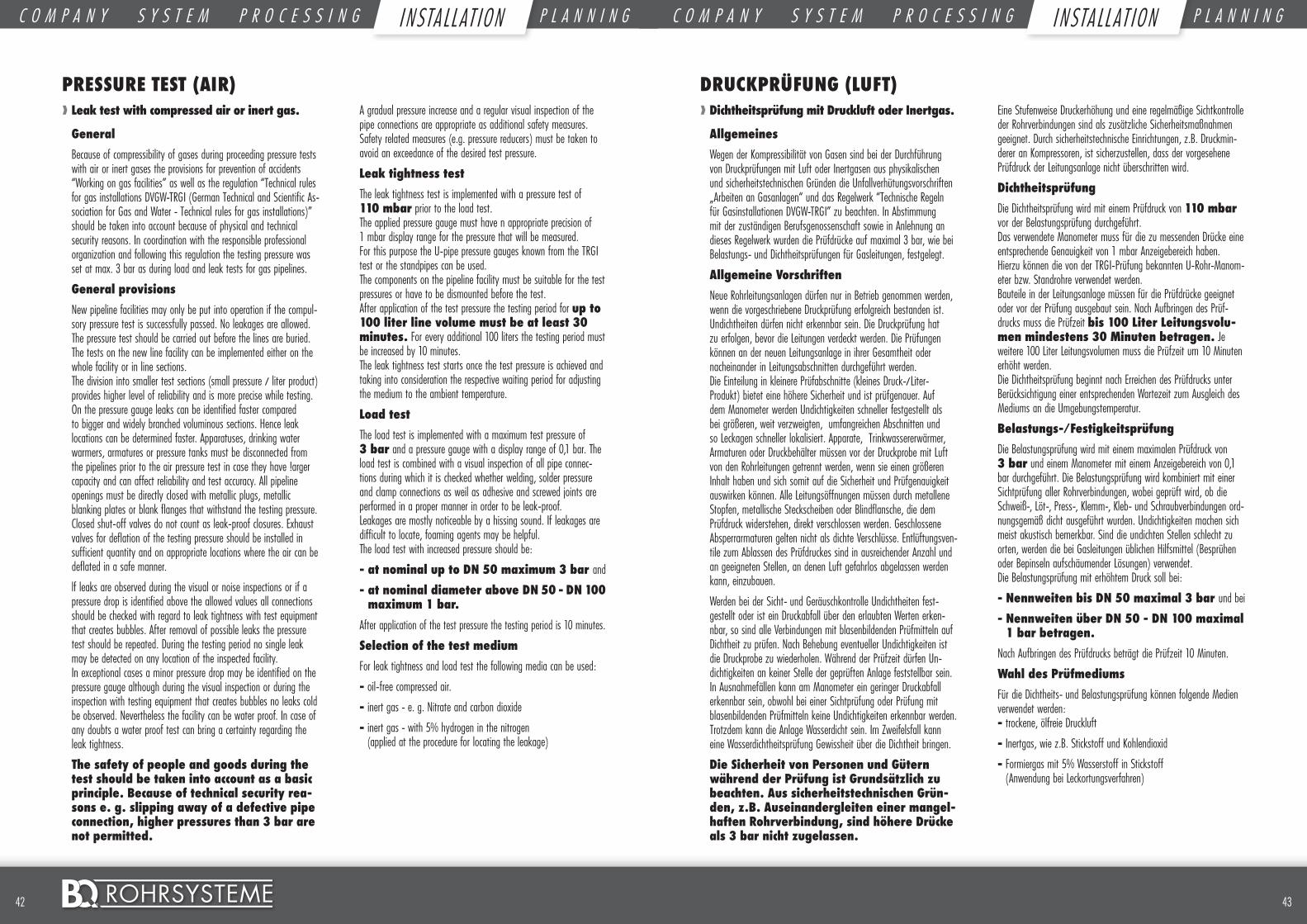
4342 ©
PRESSURE TEST (AIR)❱❱ Leak test with compressed air or inert gas.
General
Because of compressibility of gases during proceeding pressure tests with air or inert gases the provisions for prevention of accidents “Working on gas facilities” as well as the regulation “Technical rules for gas installations DVGW-TRGI (German Technical and Scientific As-sociation for Gas and Water - Technical rules for gas installations)” should be taken into account because of physical and technical security reasons. In coordination with the responsible professional organization and following this regulation the testing pressure was set at max. 3 bar as during load and leak tests for gas pipelines.
General provisions
New pipeline facilities may only be put into operation if the compul-sory pressure test is successfully passed. No leakages are allowed. The pressure test should be carried out before the lines are buried. The tests on the new line facility can be implemented either on the whole facility or in line sections. The division into smaller test sections (small pressure / liter product) provides higher level of reliability and is more precise while testing. On the pressure gauge leaks can be identified faster compared to bigger and widely branched voluminous sections. Hence leak locations can be determined faster. Apparatuses, drinking water warmers, armatures or pressure tanks must be disconnected from the pipelines prior to the air pressure test in case they have !arger capacity and can affect reliability and test accuracy. All pipeline openings must be directly closed with metallic plugs, metallic blanking plates or blank flanges that withstand the testing pressure. Closed shut-off valves do not count as leak-proof closures. Exhaust valves for deflation of the testing pressure should be installed in sufficient quantity and on appropriate locations where the air can be deflated in a safe manner.
lf leaks are observed during the visual or noise inspections or if a pressure drop is identified above the allowed values all connections should be checked with regard to leak tightness with test equipment that creates bubbles. After removal of possible leaks the pressure test should be repeated. During the testing period no single leak may be detected on any location of the inspected facility. In exceptional cases a minor pressure drop may be identified on the pressure gauge although during the visual inspection or during the inspection with testing equipment that creates bubbles no leaks cold be observed. Nevertheless the facility can be water proof. In case of any doubts a water proof test can bring a certainty regarding the leak tightness.
The safety of people and goods during the test should be taken into account as a basic principle. Because of technical security rea-sons e. g. slipping away of a defective pipe connection, higher pressures than 3 bar are not permitted.
A gradual pressure increase and a regular visual inspection of the pipe connections are appropriate as additional safety measures. Safety related measures (e.g. pressure reducers) must be taken to avoid an exceedance of the desired test pressure.
Leak tightness test
The leak tightness test is implemented with a pressure test of 110 mbar prior to the load test. The applied pressure gauge must have n appropriate precision of 1 mbar display range for the pressure that will be measured. For this purpose the U-pipe pressure gauges known from the TRGI test or the standpipes can be used. The components on the pipeline facility must be suitable for the test pressures or have to be dismounted before the test. After application of the test pressure the testing period for up to 100 liter line volume must be at least 30 minutes. For every additional 100 liters the testing period must be increased by 10 minutes. The leak tightness test starts once the test pressure is achieved and taking into consideration the respective waiting period for adjusting the medium to the ambient temperature.
Load test
The load test is implemented with a maximum test pressure of 3 bar and a pressure gauge with a display range of 0,1 bar. The load test is combined with a visual inspection of all pipe connec-tions during which it is checked whether welding, solder pressure and clamp connections as weil as adhesive and screwed joints are performed in a proper manner in order to be leak-proof. Leakages are mostly noticeable by a hissing sound. If leakages are difficult to locate, foaming agents may be helpful. The load test with increased pressure should be:
- at nominal up to DN 50 maximum 3 bar and
- at nominal diameter above DN 50 - DN 100 maximum 1 bar.
After application of the test pressure the testing period is 10 minutes.
Selection of the test medium
For leak tightness and load test the following media can be used:
- oil-free compressed air.
- inert gas - e. g. Nitrate and carbon dioxide
- inert gas - with 5% hydrogen in the nitrogen (applied at the procedure for locating the leakage)
DRUCKPRÜFUNG (LUFT)❱❱ Dichtheitsprüfung mit Druckluft oder Inertgas.
Allgemeines
Wegen der Kompressibilität von Gasen sind bei der Durchführung von Druckprüfungen mit Luft oder Inertgasen aus physikalischen und sicherheitstechnischen Gründen die Unfallverhütungsvorschriften „Arbeiten an Gasanlagen“ und das Regelwerk “Technische Regeln für Gasinstallationen DVGW-TRGI” zu beachten. In Abstimmung mit der zuständigen Berufsgenossenschaft sowie in Anlehnung an dieses Regelwerk wurden die Prüfdrücke auf maximal 3 bar, wie bei Belastungs- und Dichtheitsprüfungen für Gasleitungen, festgelegt.
Allgemeine Vorschriften
Neue Rohrleitungsanlagen dürfen nur in Betrieb genommen werden, wenn die vorgeschriebene Druckprüfung erfolgreich bestanden ist. Undichtheiten dürfen nicht erkennbar sein. Die Druckprüfung hat zu erfolgen, bevor die Leitungen verdeckt werden. Die Prüfungen können an der neuen Leitungsanlage in ihrer Gesamtheit oder nacheinander in Leitungsabschnitten durchgeführt werden. Die Einteilung in kleinere Prüfabschnitte (kleines Druck-/Liter-Produkt) bietet eine höhere Sicherheit und ist prüfgenauer. Auf dem Manometer werden Undichtigkeiten schneller festgestellt als bei größeren, weit verzweigten, umfangreichen Abschnitten und so Leckagen schneller lokalisiert. Apparate, Trinkwassererwärmer, Armaturen oder Druckbehälter müssen vor der Druckprobe mit Luft von den Rohrleitungen getrennt werden, wenn sie einen größeren Inhalt haben und sich somit auf die Sicherheit und Prüfgenauigkeit auswirken können. Alle Leitungsöffnungen müssen durch metallene Stopfen, metallische Steckscheiben oder Blindflansche, die dem Prüfdruck widerstehen, direkt verschlossen werden. Geschlossene Absperrarmaturen gelten nicht als dichte Verschlüsse. Entlüftungsven-tile zum Ablassen des Prüfdruckes sind in ausreichender Anzahl und an geeigneten Stellen, an denen Luft gefahrlos abgelassen werden kann, einzubauen.
Werden bei der Sicht- und Geräuschkontrolle Undichtheiten fest-gestellt oder ist ein Druckabfall über den erlaubten Werten erken-nbar, so sind alle Verbindungen mit blasenbildenden Prüfmitteln auf Dichtheit zu prüfen. Nach Behebung eventueller Undichtigkeiten ist die Druckprobe zu wiederholen. Während der Prüfzeit dürfen Un-dichtigkeiten an keiner Stelle der geprüften Anlage feststellbar sein. In Ausnahmefällen kann am Manometer ein geringer Druckabfall erkennbar sein, obwohl bei einer Sichtprüfung oder Prüfung mit blasenbildenden Prüfmitteln keine Undichtigkeiten erkennbar werden. Trotzdem kann die Anlage Wasserdicht sein. Im Zweifelsfall kann eine Wasserdichtheitsprüfung Gewissheit über die Dichtheit bringen.
Die Sicherheit von Personen und Gütern während der Prüfung ist Grundsätzlich zu beachten. Aus sicherheitstechnischen Grün-den, z.B. Auseinandergleiten einer mangel-haften Rohrverbindung, sind höhere Drücke als 3 bar nicht zugelassen.
Eine Stufenweise Druckerhöhung und eine regelmäßige Sichtkontrolle der Rohrverbindungen sind als zusätzliche Sicherheitsmaßnahmen geeignet. Durch sicherheitstechnische Einrichtungen, z.B. Druckmin-derer an Kompressoren, ist sicherzustellen, dass der vorgesehene Prüfdruck der Leitungsanlage nicht überschritten wird.
Dichtheitsprüfung
Die Dichtheitsprüfung wird mit einem Prüfdruck von 110 mbar vor der Belastungsprüfung durchgeführt. Das verwendete Manometer muss für die zu messenden Drücke eine entsprechende Genauigkeit von 1 mbar Anzeigebereich haben. Hierzu können die von der TRGI-Prüfung bekannten U-Rohr-Manom-eter bzw. Standrohre verwendet werden. Bauteile in der Leitungsanlage müssen für die Prüfdrücke geeignet oder vor der Prüfung ausgebaut sein. Nach Aufbringen des Prüf-drucks muss die Prüfzeit bis 100 Liter Leitungsvolu-men mindestens 30 Minuten betragen. Je weitere 100 Liter Leitungsvolumen muss die Prüfzeit um 10 Minuten erhöht werden. Die Dichtheitsprüfung beginnt nach Erreichen des Prüfdrucks unter Berücksichtigung einer entsprechenden Wartezeit zum Ausgleich des Mediums an die Umgebungstemperatur.
Belastungs-/Festigkeitsprüfung
Die Belastungsprüfung wird mit einem maximalen Prüfdruck von 3 bar und einem Manometer mit einem Anzeigebereich von 0,1 bar durchgeführt. Die Belastungsprüfung wird kombiniert mit einer Sichtprüfung aller Rohrverbindungen, wobei geprüft wird, ob die Schweiß-, Löt-, Press-, Klemm-, Kleb- und Schraubverbindungen ord-nungsgemäß dicht ausgeführt wurden. Undichtigkeiten machen sich meist akustisch bemerkbar. Sind die undichten Stellen schlecht zu orten, werden die bei Gasleitungen üblichen Hilfsmittel (Besprühen oder Bepinseln aufschäumender Lösungen) verwendet. Die Belastungsprüfung mit erhöhtem Druck soll bei:
- Nennweiten bis DN 50 maximal 3 bar und bei
- Nennweiten über DN 50 - DN 100 maximal 1 bar betragen.
Nach Aufbringen des Prüfdrucks beträgt die Prüfzeit 10 Minuten.
Wahl des Prüfmediums
Für die Dichtheits- und Belastungsprüfung können folgende Medien verwendet werden: - trockene, ölfreie Druckluft
- Inertgas, wie z.B. Stickstoff und Kohlendioxid
- Formiergas mit 5% Wasserstoff in Stickstoff (Anwendung bei Leckortungsverfahren)
C O M P A N Y S Y S T E M P R O C E S S I N G I N S T A L L A T I O N P L A N N I N G C O M P A N Y S Y S T E M P R O C E S S I N G I N S T A L L A T I O N P L A N N I N GI N STA LL AT I ON I NSTA LL AT I ON
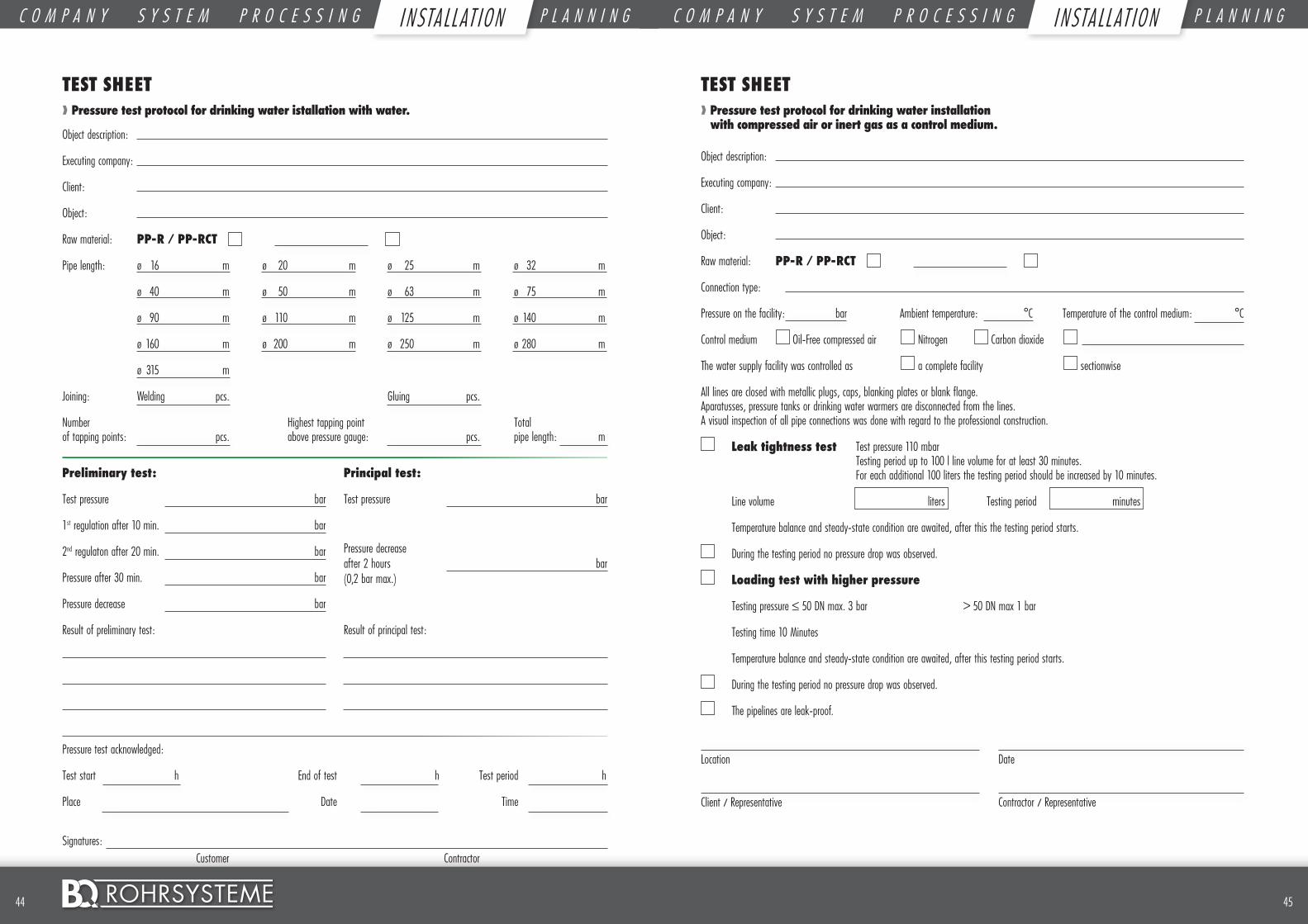
4544 ©
TEST SHEET ❱❱ Pressure test protocol for drinking water installation with compressed air or inert gas as a control medium.
Object description:
Executing company:
Client:
Object:
Raw material: PP-R / PP-RCT
Connection type:
Pressure on the facility: bar Ambient temperature: °C Temperature of the control medium: °C
Control medium Oil-Free compressed air Nitrogen Carbon dioxide
The water supply facility was controlled as a complete facility sectionwise
All lines are closed with metallic plugs, caps, blanking plates or blank flange. Aparatusses, pressure tanks or drinking water warmers are disconnected from the lines. A visual inspection of all pipe connections was done with regard to the professional construction.
Leak tightness test Test pressure 110 mbar Testing period up to 100 l line volume for at least 30 minutes. For each additional 100 liters the testing period should be increased by 10 minutes.
Line volume liters Testing period minutes
Temperature balance and steady-state condition are awaited, after this the testing period starts.
During the testing period no pressure drop was observed.
Loading test with higher pressure
Testing pressure ≤ 50 DN max. 3 bar > 50 DN max 1 bar
Testing time 10 Minutes
Temperature balance and steady-state condition are awaited, after this testing period starts.
During the testing period no pressure drop was observed.
The pipelines are leak-proof.
Location
Client / Representative
Date
Contractor / Representative
Pressure test acknowledged:
Test start h End of test h Test period h
Place Date Time
Signatures: Customer Contractor
TEST SHEET ❱❱ Pressure test protocol for drinking water istallation with water.
Object description:
Executing company:
Client:
Object:
Raw material: PP-R / PP-RCT
Pipe length: ø 16 m ø 20 m ø 25 m ø 32 m
ø 40 m ø 50 m ø 63 m ø 75 m
ø 90 m ø 110 m ø 125 m ø 140 m
ø 160 m ø 200 m ø 250 m ø 280 m
ø 315 m
Joining: Welding pcs. Gluing pcs.
Number Highest tapping point Total of tapping points: pcs. above pressure gauge: pcs. pipe length: m
Preliminary test:
Test pressure bar
1st regulation after 10 min. bar
2nd regulaton after 20 min. bar
Pressure after 30 min. bar
Pressure decrease bar
Result of preliminary test:
Principal test:
Test pressure bar
Pressure decreaseafter 2 hours bar(0,2 bar max.)
Result of principal test:
C O M P A N Y S Y S T E M P R O C E S S I N G I N S T A L L A T I O N P L A N N I N G C O M P A N Y S Y S T E M P R O C E S S I N G I N S T A L L A T I O N P L A N N I N GI N STA LL AT I ON I NSTA LL AT I ON
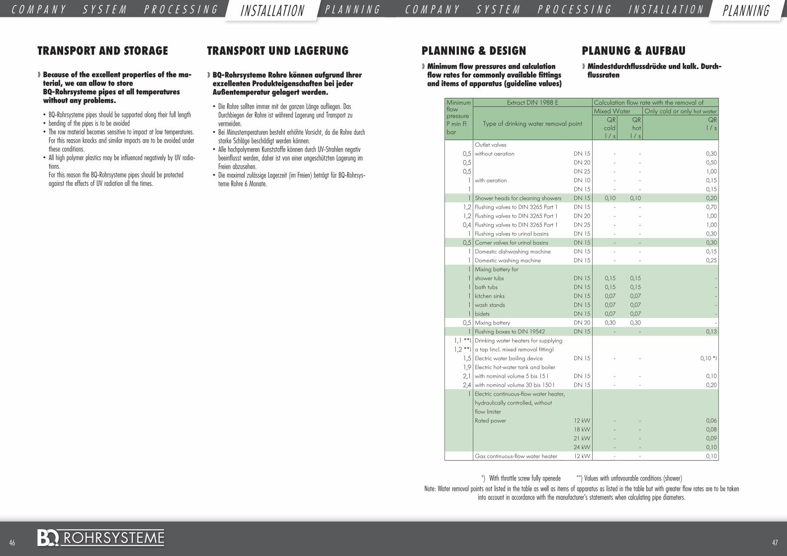
4746 ©
TRANSPORT AND STORAGE
❱❱ Because of the excellent properties of the ma-terial, we can allow to store BQ-Rohrsysteme pipes at all temperatures without any problems.
• BQ-Rohrsysteme pipes should be supported along their full length• bending of the pipes is to be avoided• The row material becomes sensitive to impact at low temperatures.
For this reason knocks and similar impacts are to be avoided under these conditions.
• All high polymer plastics may be influenced negatively by UV radia-tions. For this reason the BQ-Rohrsysteme pipes should be protected against the effects of UV radiation all the times.
TRANSPORT UND LAGERUNG
❱❱ BQ-Rohrsysteme Rohre können aufgrund Ihrer exzellenten Produkteigenschaften bei jeder Außentemperatur gelagert werden.
• Die Rohre sollten immer mit der ganzen Länge aufliegen. Das Durchbiegen der Rohre ist während Lagerung und Transport zu vermeiden.
• Bei Minustemperaturen besteht erhöhte Vorsicht, da die Rohre durch starke Schläge beschädigt werden können.
• Alle hochpolymeren Kunststoffe können durch UV-Strahlen negativ beeinflusst werden, daher ist von einer ungeschützten Lagerung im Freien abzusehen.
• Die maximal zulässige Lagerzeit (im Freien) beträgt für BQ-Rohrsys-teme Rohre 6 Monate.
Minimum flow pressureP min Flbar
Extract DIN 1988 E Calculation flow rate with the removal of
Type of drinking water removal point
Mixed Water Only cold or only hot waterQR
coldl / s
QRhotl / s
QRl / s
Outlet valves
0,5 without aeration DN 15 - - 0,30
0,5 DN 20 - - 0,50
0,5 DN 25 - - 1,00
1 with aeration DN 10 - - 0,15
1 DN 15 - - 0,15
1 Shower heads for cleaning showers DN 15 0,10 0,10 0,20
1,2 Flushing valves to DIN 3265 Part 1 DN 15 - - 0,70
1,2 Flushing valves to DIN 3265 Part 1 DN 20 - - 1,00
0,4 Flushing valves to DIN 3265 Part 1 DN 25 - - 1,00
1 Flushing valves to urinal basins DN 15 - - 0,30
0,5 Corner valves for urinal basins DN 15 - - 0,30
1 Domestic dishwashing machine DN 15 - - 0,15
1 Domestic washing machine DN 15 - - 0,25
1 Mixing battery for
1 shower tubs DN 15 0,15 0,15 -
1 bath tubs DN 15 0,15 0,15 -
1 kitchen sinks DN 15 0,07 0,07 -
1 wash stands DN 15 0,07 0,07 -
1 bidets DN 15 0,07 0,07 -
0,5 Mixing battery DN 20 0,30 0,30 -
1 Flushing boxes to DIN 19542 DN 15 - - 0,13
1,1 **) Drinking water heaters for supplying
1,2 **) a tap (incl. mixed removal fitting)
1,5 Electric water boiling device DN 15 - - 0,10 *)
1,9 Electric hot-water tank and boiler
2,1 with nominal volume 5 bis 15 l DN 15 - - 0,10
2,4 with nominal volume 30 bis 150 l DN 15 - - 0,20
1 Electric continuous-flow water heater,
hydraulically controlled, without
flow limiter
Rated power 12 kW - - 0,06
18 kW - - 0,08
21 kW - - 0,09
24 kW - - 0,10
Gas continuous-flow water heater 12 kW - - 0,10
*) With throttle screw fully openede **) Values with unfavourable conditions (shower)Note: Water removal points not listed in the table as well as items of apparatus as listed in the table but with greater flow rates are to be taken
into account in accordance with the manufacturer’s statements when calculating pipe diameters.
PLANNING & DESIGN❱❱ Minimum flow pressures and calculation flow rates for commonly available fittings and items of apparatus (guideline values)
PLANUNG & AUFBAU❱❱ Mindestdurchflussdrücke und kalk. Durch-flussraten
C O M P A N Y S Y S T E M P R O C E S S I N G I N S T A L L A T I O N P L A N N I N GP L AN N I NGC O M P A N Y S Y S T E M P R O C E S S I N G I N S T A L L A T I O N P L A N N I N GI NSTA LL AT I ON
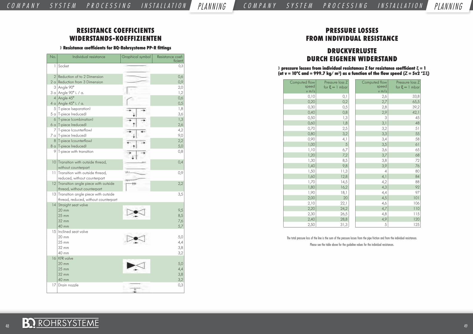
4948 ©
RESISTANCE COEFFICIENTS WIDERSTANDS-KOEFFIZIENTEN
❱❱ Resistance coefficients for BQ-Rohrsysteme PP-R fittings
No. Individual resistance Graphical symbol Resistance coef-ficient
1 Socket 0,3
2 Reduction of to 2 Dimension 0,62 a Reduction from 3 Dimension 0,9
3 Angle 90° 2,03 a Angle 90° i. / a. 1,2
4 Angle 45° 0,64 a Angle 45° i. / a. 0,5
5 T-piece (separation) 1,85 a T-piece (reduced) 3,6
6 T-piece (combination) 1,36 a T-piece (reduced) 2,6
7 T-piece (counterflow) 4,27 a T-piece (reduced) 9,0
8 T-piece (counterflow) 2,28 a T-piece (reduced) 5,0
9 T-piece with transition 0,8
10 Transition with outside thread, 0,4without counterpart
11 Transition with outside thread, 0,9reduced, without counterpart
12 Transition angle piece with outside 2,2thread, without counterpart
13 Transition angle piece with outside 3,5thread, reduced, without counterpart
14 Straight seat valve20 mm 9,525 mm 8,532 mm 7,640 mm 5,7
15 Inclined seat valve20 mm 5,025 mm 4,432 mm 3,840 mm 3,2
16 KFR valve20 mm 5,025 mm 4,432 mm 3,840 mm 3,2
17 Drain nozzle 0,3
PRESSURE LOSSES FROM INDIVIDUAL RESISTANCE
DRUCKVERLUSTE DURCH EIGENEN WIDERSTAND
❱❱ pressure losses from individual resistances Z for resistance coefficient ξ = 1 (at v = 10°C and = 999.7 kg/ m³) as a function of the flow speed (Ζ = 5v2 *Σξ)
Computed flow speedv m/s
Pressure loss Zfor ξ = 1 mbar
Computed flow speedv m/s
Pressure loss Zfor ξ = 1 mbar
0,10 0,1 2,6 33,80,20 0,2 2,7 65,50,30 0,5 2,8 39,20,40 0,8 2,9 42,10,50 1,3 3 450,60 1,8 3,1 480,70 2,5 3,2 510,80 3,2 3,3 550,90 4,1 3,4 581,00 5 3,5 611,10 6,7 3,6 651,20 7,2 3,7 681,30 8,5 3,8 721,40 9,8 3,9 761,50 11,3 4 801,60 12,8 4,1 841,70 14,5 4,2 881,80 16,2 4,3 921,90 18,1 4,4 972,00 20 4,5 1012,10 22,1 4,6 1062,20 24,2 4,7 1102,30 26,5 4,8 1152,40 28,8 4,9 1202,50 31,3 5 125
The total pressure loss of the line is the sum of the pressure losses from the pipe friction and from the individual resistances.
Please see the table above for the guideline values for the individual resistances.
C O M P A N Y S Y S T E M P R O C E S S I N G I N S T A L L A T I O N P L A N N I N G C O M P A N Y S Y S T E M P R O C E S S I N G I N S T A L L A T I O N P L A N N I N GP L AN N I NG P L AN N I NG
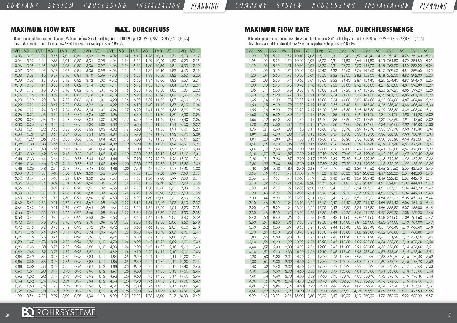
5150 ©
MAXIMUM FLOW RATE MAX. DURCHFLUSSDetermination of the maximum flow rate Vs from the flow ΣVR for buildings acc. to DIN 1988 part 3 - VS - 0,682 · (ΣVR)0,45 - 0,14 [l/s] This table is valid, if the calculated flow VR of the respective water points in < 0,5 l/s.
ΣVR VS ΣVR VS ΣVR VS ΣVR VS ΣVR VS ΣVR VS ΣVR VS ΣVR VS0,03 0,00 1,02 0,55 2,02 0,80 3,02 0,98 4,02 1,14 5,10 1,28 10,10 1,79 15,10 2,170,04 0,02 1,04 0,55 2,04 0,80 3,04 0,98 4,04 1,14 5,20 1,29 10,20 1,80 15,20 2,180,06 0,05 1,06 0,56 2,06 0,80 3,06 0,99 4,06 1,14 5,30 1,30 10,30 1,81 15,30 2,190,07 0,07 1,08 0,57 2,08 0,81 3,08 0,99 4,08 1,14 5,40 1,32 10,40 1,82 15,40 2,190,08 0,08 1,10 0,57 2,10 0,81 3,10 0,99 4,10 1,15 5,50 1,33 10,50 1,82 15,50 2,200,09 0,09 1,12 0,58 2,12 0,82 3,12 1,00 4,12 1,15 5,60 1,34 10,60 1,83 15,60 2,210,10 0,10 1,14 0,58 2,14 0,82 3,14 1,00 4,14 1,15 5,70 1,35 10,70 1,84 15,70 2,210,13 0,13 1,16 0,59 2,16 0,82 3,16 1,00 4,16 1,16 5,80 1,36 10,80 1,85 15,80 2,220,15 0,15 1,18 0,59 2,18 0,83 3,18 1,01 4,18 1,16 5,90 1,38 10,90 1,86 15,90 2,230,20 0,19 1,20 0,6 2,20 0,83 3,20 1,01 4,20 1,16 6,00 1,39 11,00 1,87 16,00 2,230,22 0,21 1,22 0,61 2,22 0,84 3,22 1,01 4,22 1,16 6,10 1,40 11,10 1,87 16,10 2,240,24 0,22 1,24 0,61 2,24 0,84 3,24 1,02 4,24 1,17 6,20 1,41 11,20 1,88 16,20 2,250,26 0,23 1,26 0,62 2,26 0,84 3,26 1,02 4,26 1,17 6,30 1,42 11,30 1,89 16,30 2,250,28 0,24 1,28 0,62 2,28 0,85 3,28 1,02 4,28 1,17 6,40 1,43 11,40 1,90 16,40 2,260,30 0,26 1,30 0,63 2,30 0,85 3,30 1,03 4,30 1,17 6,50 1,44 11,50 1,91 16,50 2,270,32 0,27 1,32 0,63 2,32 0,86 3,32 1,03 4,32 1,18 6,60 1,45 11,60 1,91 16,60 2,270,34 0,28 1,34 0,64 2,34 0,86 3,34 1,03 4,34 1,18 6,70 1,47 11,70 1,92 16,70 2,280,36 0,29 1,36 0,64 2,36 0,86 3,36 1,04 4,36 1,18 6,80 1,48 11,80 1,93 16,80 2,290,38 0,30 1,38 0,65 2,38 0,87 3,38 1,04 4,38 1,19 6,90 1,49 11,90 1,94 16,90 2,290,40 0,31 1,40 0,65 2,40 0,87 3,40 1,04 4,40 1,19 7,00 1,50 12,00 1,95 17,00 2,300,42 0,32 1,42 0,66 2,42 0,88 3,42 1,05 4,42 1,19 7,10 1,51 12,10 1,95 17,10 2,310,44 0,33 1,44 0,66 2,44 0,88 3,44 1,05 4,44 1,19 7,20 1,52 12,20 1,96 17,20 2,310,46 0,34 1,46 0,67 2,46 0,88 3,46 1,05 4,46 1,20 7,30 1,53 12,30 1,97 17,30 2,320,48 0,35 1,48 0,67 2,48 0,89 3,48 1,06 4,48 1,20 7,40 1,54 12,40 1,98 17,40 2,330,50 0,36 1,50 0,68 2,50 0,89 3,50 1,06 4,50 1,20 7,50 1,55 12,50 1,99 17,50 2,330,52 0,37 1,52 0,68 2,52 0,89 3,52 1,06 4,52 1,20 7,60 1,56 12,60 1,99 17,60 2,340,54 0,38 1,54 0,69 2,54 0,90 3,54 1,06 4,54 1,21 7,70 1,57 12,70 2,00 17,70 2,350,56 0,39 1,56 0,69 2,56 0,90 3,56 1,07 4,56 1,21 7,80 1,58 12,80 2,01 17,80 2,350,58 0,39 1,58 0,7 2,58 0,90 3,58 1,07 4,58 1,21 7,90 1,59 12,90 2,02 17,90 2,360,60 0,40 1,60 0,7 2,60 0,91 3,60 1,07 4,60 1,22 8,00 1,60 13,00 2,02 18,00 2,360,62 0,41 1,62 0,71 2,62 0,91 3,62 1,08 4,62 1,22 8,10 1,61 13,10 2,03 18,10 2,370,64 0,42 1,64 0,71 2,64 0,92 3,64 1,08 4,64 1,22 8,20 1,62 13,20 2,04 18,20 2,380,66 0,43 1,66 0,72 2,66 0,92 3,66 1,08 4,66 1,22 8,30 1,63 13,30 2,05 18,30 2,380,68 0,43 1,68 0,72 2,68 0,92 3,68 1,09 4,68 1,23 8,40 1,64 13,40 2,05 18,40 2,390,70 0,44 1,70 0,73 2,70 0,93 3,70 1,09 4,70 1,23 8,50 1,65 13,50 2,06 18,50 2,400,72 0,45 1,72 0,73 2,72 0,93 3,72 1,09 4,72 1,23 8,60 1,66 13,60 2,07 18,60 2,400,74 0,46 1,74 0,74 2,74 0,93 3,74 1,09 4,74 1,23 8,70 1,67 13,70 2,07 18,70 2,410,76 0,46 1,76 0,74 2,76 0,94 3,76 1,10 4,76 1,24 8,80 1,67 13,80 2,08 18,80 2,410,78 0,47 1,78 0,74 2,78 0,94 3,78 1,10 4,78 1,24 8,90 1,68 13,90 2,09 18,90 2,420,80 0,48 1,80 0,75 2,80 0,94 3,80 1,10 4,80 1,24 9,00 1,69 14,00 2,10 19,00 2,430,82 0,48 1,82 0,75 2,82 0,95 3,82 1,11 4,82 1,24 9,10 1,70 14,10 2,10 19,10 2,430,84 0,49 1,84 0,76 2,84 0,95 3,84 1,11 4,84 1,25 9,20 1,71 14,20 2,11 19,20 2,440,86 0,50 1,86 0,76 2,86 0,95 3,86 1,11 4,86 1,25 9,30 1,72 14,30 2,12 19,30 2,440,88 0,50 1,88 0,77 2,88 0,96 3,88 1,12 4,88 1,25 9,40 1,73 14,40 2,12 19,40 2,450,90 0,51 1,90 0,77 2,90 0,96 3,90 1,12 4,90 1,25 9,50 1,74 14,50 2,13 19,50 2,460,92 0,52 1,92 0,77 2,92 0,96 3,92 1,12 4,92 1,26 9,60 1,75 14,60 2,14 19,60 2,460,94 0,52 1,94 0,78 2,94 0,97 3,94 1,12 4,94 1,26 9,70 1,76 14,70 2,15 19,70 2,470,96 0,53 1,96 0,78 2,96 0,97 3,96 1,13 4,96 1,26 9,80 1,76 14,80 2,15 19,80 2,470,98 0,54 1,98 0,79 2,98 0,97 3,98 1,13 4,98 1,26 9,90 1,77 14,90 2,16 19,90 2,481,00 0,54 2,00 0,79 3,00 0,98 4,00 1,13 5,00 1,27 10,00 1,78 15,00 2,17 20,00 2,49
MAXIMUM FLOW RATE MAX. DURCHFLUSSMENGEDetermination of the maximum flow rate Vs from the total flow ΣVR for buildings acc. to DIN 1988 part 3 · VS = 1,7 · (ΣVR)0,21 - 0,7 [l/s] This table is valid, if the calculated flow VR of the respective water points in < 0,5 l/s.
ΣVR VS ΣVR VS ΣVR VS ΣVR VS ΣVR VS ΣVR VS ΣVR VS ΣVR VS1,00 1,00 5,10 1,69 10,10 2,06 15,10 2,31 22,40 2,57 142,40 4,12 262,40 4,78 382,40 5,231,05 1,02 5,20 1,70 10,20 2,07 15,20 2,31 24,80 2,64 144,80 4,13 264,80 4,79 384,80 5,231,10 1,03 5,30 1,71 10,30 2,07 15,30 2,31 27,20 2,70 147,20 4,15 267,20 4,80 387,20 5,241,15 1,05 5,40 1,72 10,40 2,08 15,40 2,32 29,60 2,76 149,60 4,17 269,60 4,81 389,60 5,251,20 1,07 5,50 1,73 10,50 2,09 15,50 2,32 32,00 2,82 152,00 4,18 272,00 4,82 392,00 5,261,25 1,08 5,60 1,74 10,60 2,09 15,60 2,33 34,40 2,87 154,40 4,20 274,40 4,83 394,40 5,261,30 1,10 5,70 1,75 10,70 2,10 15,70 2,33 36,80 2,92 156,80 4,21 276,80 4,84 396,80 5,271,35 1,11 5,80 1,76 10,80 2,10 15,80 2,34 39,20 2,97 159,20 4,23 279,20 4,85 399,20 5,281,40 1,12 5,90 1,77 10,90 2,11 15,90 2,34 41,60 3,02 161,60 4,25 281,60 4,86 401,60 5,291,45 1,14 6,00 1,78 11,00 2,11 16,00 2,34 44,00 3,06 164,00 4,26 284,00 4,87 404,00 5,291,50 1,15 6,10 1,79 11,10 2,12 16,10 2,35 46,40 3,11 166,40 4,28 286,40 4,88 406,40 5,301,55 1,16 6,20 1,79 11,20 2,12 16,20 2,35 48,80 3,15 168,80 4,29 288,80 4,89 408,80 5,311,60 1,18 6,30 1,80 11,30 2,13 16,30 2,35 51,20 3,19 171,20 4,31 291,20 4,90 411,20 5,321,65 1,19 6,40 1,81 11,40 2,13 16,40 2,36 53,60 3,22 173,60 4,32 293,60 4,91 413,60 5,321,70 1,20 6,50 1,82 11,50 2,14 16,50 2,36 56,00 3,26 176,00 4,34 296,00 4,92 416,00 5,331,75 1,21 6,60 1,83 11,60 2,14 16,60 2,37 58,40 3,29 178,40 4,35 298,40 4,93 418,40 5,341,80 1,22 6,70 1,83 11,70 2,15 16,70 2,37 60,80 3,33 180,80 4,36 300,80 4,93 420,80 5,351,85 1,23 6,80 1,84 11,80 2,15 16,80 2,37 63,20 3,36 183,20 4,38 303,20 4,94 423,20 5,351,90 1,25 6,90 1,85 11,90 2,16 16,90 2,38 65,60 3,39 185,60 4,39 305,60 4,95 425,60 5,362,00 1,27 7,00 1,86 12,00 2,16 17,00 2,38 68,00 3,42 188,00 4,41 308,00 4,96 428,00 5,372,10 1,29 7,10 1,87 12,10 2,17 17,10 2,39 70,40 3,45 190,40 4,42 310,40 4,97 430,40 5,382,20 1,31 7,20 1,87 12,20 2,17 17,20 2,39 72,80 3,48 192,80 4,43 312,80 4,98 432,80 5,382,30 1,32 7,30 1,88 12,30 2,18 17,30 2,39 75,20 3,51 195,20 4,45 315,20 4,99 435,20 5,392,40 1,34 7,40 1,89 12,40 2,18 17,40 2,40 77,60 3,54 197,60 4,46 317,60 5,00 437,60 5,402,50 1,36 7,50 1,90 12,50 2,19 17,50 2,40 80,00 3,57 200,00 4,47 320,00 5,01 440,00 5,402,60 1,38 7,60 1,90 12,60 2,19 17,60 2,40 82,40 3,59 202,40 4,49 322,40 5,02 442,40 5,412,70 1,39 7,70 1,91 12,70 2,20 17,70 2,41 84,80 3,62 204,80 4,50 324,80 5,03 444,80 5,422,80 1,41 7,80 1,92 12,80 2,20 17,80 2,41 87,20 3,64 207,20 4,51 327,20 5,04 447,20 5,422,90 1,43 7,90 1,92 12,90 2,21 17,90 2,42 89,60 3,67 209,60 4,52 329,60 5,04 449,60 5,433,00 1,44 8,00 1,93 13,00 2,21 18,00 2,42 92,00 3,69 212,00 4,54 332,00 5,05 452,00 5,443,10 1,46 8,10 1,94 13,10 2,22 18,10 2,42 94,40 3,72 214,40 4,55 334,40 5,06 454,40 5,443,20 1,47 8,20 1,94 13,20 2,22 18,20 2,43 96,80 3,74 216,80 4,56 336,80 5,07 456,80 5,453,30 1,48 8,30 1,95 13,30 2,23 18,30 2,43 99,20 3,76 219,20 4,57 339,20 5,08 459,20 5,463,40 1,50 8,40 1,96 13,40 2,23 18,40 2,43 101,60 3,79 221,60 4,58 341,60 5,09 461,60 5,473,50 1,51 8,50 1,96 13,50 2,24 18,50 2,44 104,00 3,81 224,00 4,60 344,00 5,10 464,00 5,473,60 1,52 8,60 1,97 13,60 2,24 18,60 2,44 106,40 3,83 226,40 4,61 346,40 5,10 466,40 5,483,70 1,54 8,70 1,98 13,70 2,25 18,70 2,44 108,80 3,85 228,80 4,62 348,80 5,11 468,80 5,493,80 1,55 8,80 1,98 13,80 2,25 18,80 2,45 111,20 3,87 231,20 4,63 351,20 5,12 471,20 5,493,90 1,56 8,90 1,99 13,90 2,25 18,90 2,45 113,60 3,89 233,60 4,64 353,60 5,13 473,60 5,504,00 1,57 9,00 2,00 14,00 2,26 19,00 2,45 116,00 3,91 236,00 4,66 356,00 5,14 476,00 5,514,10 1,59 9,10 2,00 14,10 2,26 19,10 2,46 118,40 3,93 238,40 4,67 358,40 5,15 478,40 5,514,20 1,60 9,20 2,01 14,20 2,27 19,20 2,46 120,80 3,95 240,80 4,68 360,80 5,15 480,80 5,524,30 1,61 9,30 2,02 14,30 2,27 19,30 2,47 123,20 3,97 243,20 4,69 363,20 5,16 483,20 5,524,40 1,62 9,40 2,02 14,40 2,28 19,40 2,47 125,60 3,99 245,60 4,70 365,60 5,17 485,60 5,534,50 1,63 9,50 2,03 14,50 2,28 19,50 2,47 128,00 4,01 248,00 4,71 368,00 5,18 488,00 5,544,60 1,64 9,60 2,03 14,60 2,29 19,60 2,48 130,40 4,03 250,40 4,72 370,40 5,19 490,40 5,544,70 1,65 9,70 2,04 14,70 2,29 19,70 2,48 132,80 4,05 252,80 4,76 372,80 5,19 492,80 5,554,80 1,66 9,80 2,05 14,80 2,29 19,80 2,48 135,20 4,06 255,20 4,74 375,20 5,20 495,20 5,564,90 1,67 9,90 2,05 14,90 2,30 19,90 2,49 137,60 4,08 257,60 4,75 377,60 5,21 497,60 5,565,00 1,68 10,00 2,06 15,00 2,30 20,00 2,49 140,00 4,10 260,00 4,77 380,00 5,22 500,00 5,57
C O M P A N Y S Y S T E M P R O C E S S I N G I N S T A L L A T I O N P L A N N I N G C O M P A N Y S Y S T E M P R O C E S S I N G I N S T A L L A T I O N P L A N N I N GP L AN N I NG P L AN N I NG
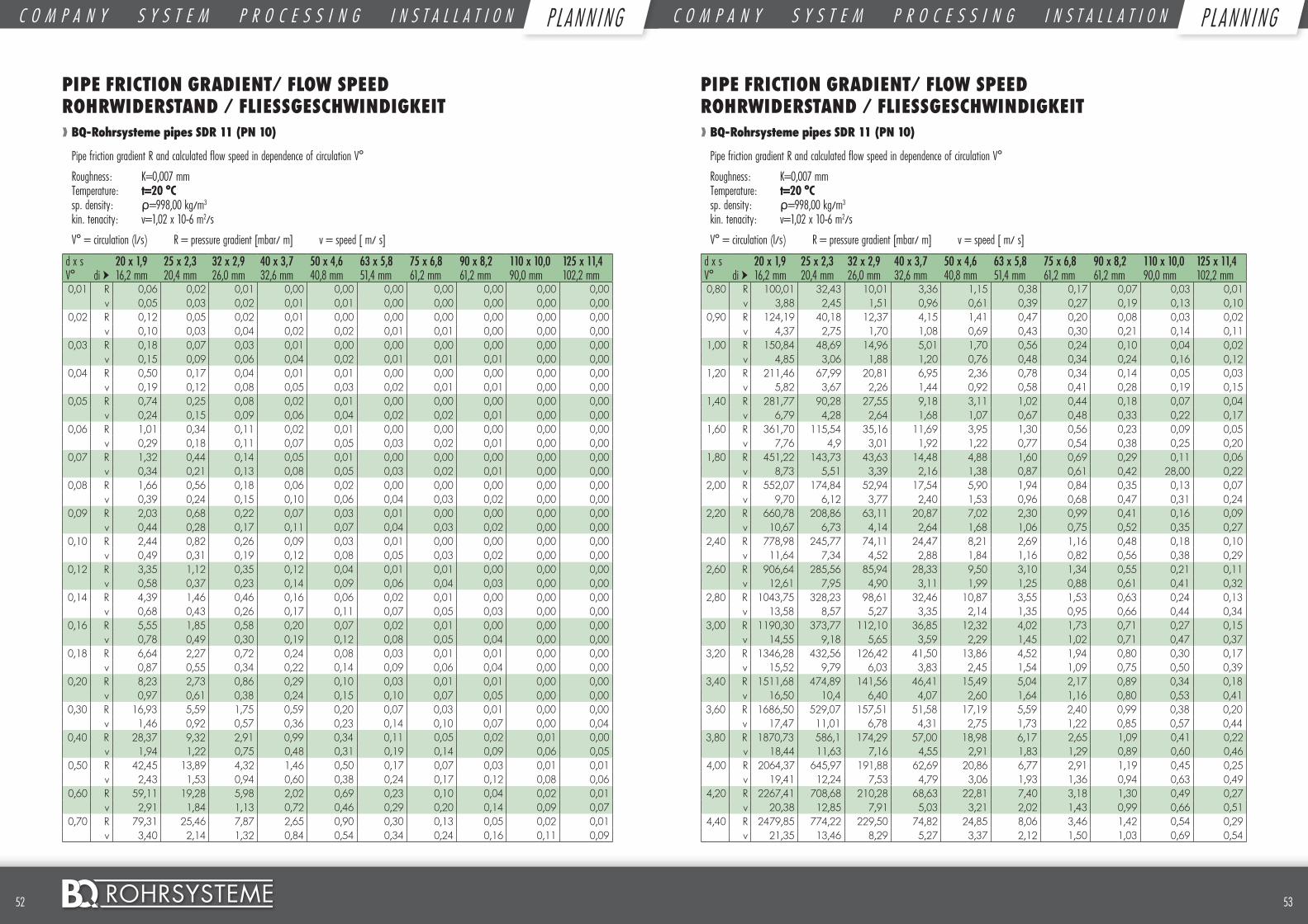
5352 ©
PIPE FRICTION GRADIENT/ FLOW SPEED ROHRWIDERSTAND / FLIESSGESCHWINDIGKEIT❱❱ BQ-Rohrsysteme pipes SDR 11 (PN 10)
Pipe friction gradient R and calculated flow speed in dependence of circulation V°
Roughness: K=0,007 mm Temperature: t=20 °C sp. density: ρ=998,00 kg/m3 kin. tenacity: v=1,02 x 10⁻⁶ m2/s
V° = circulation (l/s) R = pressure gradient [mbar/ m] v = speed [ m/ s]
d x s 20 x 1,9 25 x 2,3 32 x 2,9 40 x 3,7 50 x 4,6 63 x 5,8 75 x 6,8 90 x 8,2 110 x 10,0 125 x 11,4V° di ➤ 16,2 mm 20,4 mm 26,0 mm 32,6 mm 40,8 mm 51,4 mm 61,2 mm 61,2 mm 90,0 mm 102,2 mm 0,01 R 0,06 0,02 0,01 0,00 0,00 0,00 0,00 0,00 0,00 0,00
v 0,05 0,03 0,02 0,01 0,01 0,00 0,00 0,00 0,00 0,000,02 R 0,12 0,05 0,02 0,01 0,00 0,00 0,00 0,00 0,00 0,00
v 0,10 0,03 0,04 0,02 0,02 0,01 0,01 0,00 0,00 0,000,03 R 0,18 0,07 0,03 0,01 0,00 0,00 0,00 0,00 0,00 0,00
v 0,15 0,09 0,06 0,04 0,02 0,01 0,01 0,01 0,00 0,000,04 R 0,50 0,17 0,04 0,01 0,01 0,00 0,00 0,00 0,00 0,00
v 0,19 0,12 0,08 0,05 0,03 0,02 0,01 0,01 0,00 0,000,05 R 0,74 0,25 0,08 0,02 0,01 0,00 0,00 0,00 0,00 0,00
v 0,24 0,15 0,09 0,06 0,04 0,02 0,02 0,01 0,00 0,000,06 R 1,01 0,34 0,11 0,02 0,01 0,00 0,00 0,00 0,00 0,00
v 0,29 0,18 0,11 0,07 0,05 0,03 0,02 0,01 0,00 0,000,07 R 1,32 0,44 0,14 0,05 0,01 0,00 0,00 0,00 0,00 0,00
v 0,34 0,21 0,13 0,08 0,05 0,03 0,02 0,01 0,00 0,000,08 R 1,66 0,56 0,18 0,06 0,02 0,00 0,00 0,00 0,00 0,00
v 0,39 0,24 0,15 0,10 0,06 0,04 0,03 0,02 0,00 0,000,09 R 2,03 0,68 0,22 0,07 0,03 0,01 0,00 0,00 0,00 0,00
v 0,44 0,28 0,17 0,11 0,07 0,04 0,03 0,02 0,00 0,000,10 R 2,44 0,82 0,26 0,09 0,03 0,01 0,00 0,00 0,00 0,00
v 0,49 0,31 0,19 0,12 0,08 0,05 0,03 0,02 0,00 0,000,12 R 3,35 1,12 0,35 0,12 0,04 0,01 0,01 0,00 0,00 0,00
v 0,58 0,37 0,23 0,14 0,09 0,06 0,04 0,03 0,00 0,000,14 R 4,39 1,46 0,46 0,16 0,06 0,02 0,01 0,00 0,00 0,00
v 0,68 0,43 0,26 0,17 0,11 0,07 0,05 0,03 0,00 0,000,16 R 5,55 1,85 0,58 0,20 0,07 0,02 0,01 0,00 0,00 0,00
v 0,78 0,49 0,30 0,19 0,12 0,08 0,05 0,04 0,00 0,000,18 R 6,64 2,27 0,72 0,24 0,08 0,03 0,01 0,01 0,00 0,00
v 0,87 0,55 0,34 0,22 0,14 0,09 0,06 0,04 0,00 0,000,20 R 8,23 2,73 0,86 0,29 0,10 0,03 0,01 0,01 0,00 0,00
v 0,97 0,61 0,38 0,24 0,15 0,10 0,07 0,05 0,00 0,000,30 R 16,93 5,59 1,75 0,59 0,20 0,07 0,03 0,01 0,00 0,00
v 1,46 0,92 0,57 0,36 0,23 0,14 0,10 0,07 0,00 0,040,40 R 28,37 9,32 2,91 0,99 0,34 0,11 0,05 0,02 0,01 0,00
v 1,94 1,22 0,75 0,48 0,31 0,19 0,14 0,09 0,06 0,050,50 R 42,45 13,89 4,32 1,46 0,50 0,17 0,07 0,03 0,01 0,01
v 2,43 1,53 0,94 0,60 0,38 0,24 0,17 0,12 0,08 0,060,60 R 59,11 19,28 5,98 2,02 0,69 0,23 0,10 0,04 0,02 0,01
v 2,91 1,84 1,13 0,72 0,46 0,29 0,20 0,14 0,09 0,070,70 R 79,31 25,46 7,87 2,65 0,90 0,30 0,13 0,05 0,02 0,01
v 3,40 2,14 1,32 0,84 0,54 0,34 0,24 0,16 0,11 0,09
PIPE FRICTION GRADIENT/ FLOW SPEED ROHRWIDERSTAND / FLIESSGESCHWINDIGKEIT❱❱ BQ-Rohrsysteme pipes SDR 11 (PN 10)
Pipe friction gradient R and calculated flow speed in dependence of circulation V°
Roughness: K=0,007 mm Temperature: t=20 °C sp. density: ρ=998,00 kg/m3 kin. tenacity: v=1,02 x 10⁻⁶ m2/s
V° = circulation (l/s) R = pressure gradient [mbar/ m] v = speed [ m/ s]
d x s 20 x 1,9 25 x 2,3 32 x 2,9 40 x 3,7 50 x 4,6 63 x 5,8 75 x 6,8 90 x 8,2 110 x 10,0 125 x 11,4V° di ➤ 16,2 mm 20,4 mm 26,0 mm 32,6 mm 40,8 mm 51,4 mm 61,2 mm 61,2 mm 90,0 mm 102,2 mm 0,80 R 100,01 32,43 10,01 3,36 1,15 0,38 0,17 0,07 0,03 0,01
v 3,88 2,45 1,51 0,96 0,61 0,39 0,27 0,19 0,13 0,100,90 R 124,19 40,18 12,37 4,15 1,41 0,47 0,20 0,08 0,03 0,02
v 4,37 2,75 1,70 1,08 0,69 0,43 0,30 0,21 0,14 0,111,00 R 150,84 48,69 14,96 5,01 1,70 0,56 0,24 0,10 0,04 0,02
v 4,85 3,06 1,88 1,20 0,76 0,48 0,34 0,24 0,16 0,121,20 R 211,46 67,99 20,81 6,95 2,36 0,78 0,34 0,14 0,05 0,03
v 5,82 3,67 2,26 1,44 0,92 0,58 0,41 0,28 0,19 0,151,40 R 281,77 90,28 27,55 9,18 3,11 1,02 0,44 0,18 0,07 0,04
v 6,79 4,28 2,64 1,68 1,07 0,67 0,48 0,33 0,22 0,171,60 R 361,70 115,54 35,16 11,69 3,95 1,30 0,56 0,23 0,09 0,05
v 7,76 4,9 3,01 1,92 1,22 0,77 0,54 0,38 0,25 0,201,80 R 451,22 143,73 43,63 14,48 4,88 1,60 0,69 0,29 0,11 0,06
v 8,73 5,51 3,39 2,16 1,38 0,87 0,61 0,42 28,00 0,222,00 R 552,07 174,84 52,94 17,54 5,90 1,94 0,84 0,35 0,13 0,07
v 9,70 6,12 3,77 2,40 1,53 0,96 0,68 0,47 0,31 0,242,20 R 660,78 208,86 63,11 20,87 7,02 2,30 0,99 0,41 0,16 0,09
v 10,67 6,73 4,14 2,64 1,68 1,06 0,75 0,52 0,35 0,272,40 R 778,98 245,77 74,11 24,47 8,21 2,69 1,16 0,48 0,18 0,10
v 11,64 7,34 4,52 2,88 1,84 1,16 0,82 0,56 0,38 0,292,60 R 906,64 285,56 85,94 28,33 9,50 3,10 1,34 0,55 0,21 0,11
v 12,61 7,95 4,90 3,11 1,99 1,25 0,88 0,61 0,41 0,322,80 R 1043,75 328,23 98,61 32,46 10,87 3,55 1,53 0,63 0,24 0,13
v 13,58 8,57 5,27 3,35 2,14 1,35 0,95 0,66 0,44 0,343,00 R 1190,30 373,77 112,10 36,85 12,32 4,02 1,73 0,71 0,27 0,15
v 14,55 9,18 5,65 3,59 2,29 1,45 1,02 0,71 0,47 0,373,20 R 1346,28 432,56 126,42 41,50 13,86 4,52 1,94 0,80 0,30 0,17
v 15,52 9,79 6,03 3,83 2,45 1,54 1,09 0,75 0,50 0,393,40 R 1511,68 474,89 141,56 46,41 15,49 5,04 2,17 0,89 0,34 0,18
v 16,50 10,4 6,40 4,07 2,60 1,64 1,16 0,80 0,53 0,413,60 R 1686,50 529,07 157,51 51,58 17,19 5,59 2,40 0,99 0,38 0,20
v 17,47 11,01 6,78 4,31 2,75 1,73 1,22 0,85 0,57 0,443,80 R 1870,73 586,1 174,29 57,00 18,98 6,17 2,65 1,09 0,41 0,22
v 18,44 11,63 7,16 4,55 2,91 1,83 1,29 0,89 0,60 0,464,00 R 2064,37 645,97 191,88 62,69 20,86 6,77 2,91 1,19 0,45 0,25
v 19,41 12,24 7,53 4,79 3,06 1,93 1,36 0,94 0,63 0,494,20 R 2267,41 708,68 210,28 68,63 22,81 7,40 3,18 1,30 0,49 0,27
v 20,38 12,85 7,91 5,03 3,21 2,02 1,43 0,99 0,66 0,514,40 R 2479,85 774,22 229,50 74,82 24,85 8,06 3,46 1,42 0,54 0,29
v 21,35 13,46 8,29 5,27 3,37 2,12 1,50 1,03 0,69 0,54
C O M P A N Y S Y S T E M P R O C E S S I N G I N S T A L L A T I O N P L A N N I N G C O M P A N Y S Y S T E M P R O C E S S I N G I N S T A L L A T I O N P L A N N I N GP L AN N I NG P L AN N I NG
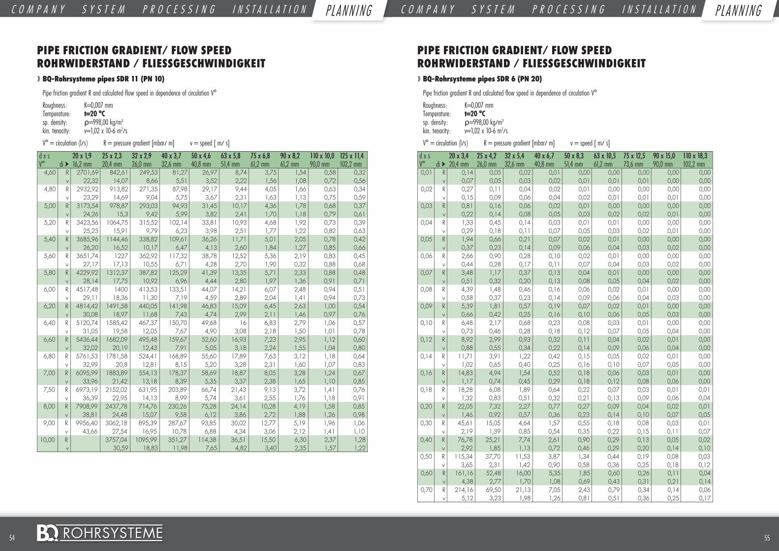
5554 ©
PIPE FRICTION GRADIENT/ FLOW SPEED ROHRWIDERSTAND / FLIESSGESCHWINDIGKEIT❱❱ BQ-Rohrsysteme pipes SDR 11 (PN 10)
Pipe friction gradient R and calculated flow speed in dependence of circulation V°
Roughness: K=0,007 mm Temperature: t=20 °C sp. density: ρ=998,00 kg/m3 kin. tenacity: v=1,02 x 10⁻⁶ m2/s
V° = circulation (l/s) R = pressure gradient [mbar/ m] v = speed [ m/ s]
d x s 20 x 1,9 25 x 2,3 32 x 2,9 40 x 3,7 50 x 4,6 63 x 5,8 75 x 6,8 90 x 8,2 110 x 10,0 125 x 11,4V° di ➤ 16,2 mm 20,4 mm 26,0 mm 32,6 mm 40,8 mm 51,4 mm 61,2 mm 61,2 mm 90,0 mm 102,2 mm
4,60 R 2701,69 842,61 249,53 81,27 26,97 8,74 3,75 1,54 0,58 0,32v 22,32 14,07 8,66 5,51 3,52 2,22 1,56 1,08 0,72 0,56
4,80 R 2932,92 913,82 271,35 87,98 29,17 9,44 4,05 1,66 0,63 0,34v 23,29 14,69 9,04 5,75 3,67 2,31 1,63 1,13 0,75 0,59
5,00 R 3173,54 978,87 293,03 94,93 31,45 10,17 4,36 1,78 0,68 0,37v 24,26 15,3 9,42 5,99 3,82 2,41 1,70 1,18 0,79 0,61
5,20 R 3423,56 1064,75 315,52 102,14 33,81 10,93 4,68 1,92 0,73 0,39v 25,23 15,91 9,79 6,23 3,98 2,51 1,77 1,22 0,82 0,63
5,40 R 3685,96 1144,46 338,82 109,61 36,26 11,71 5,01 2,05 0,78 0,42v 26,20 16,52 10,17 6,47 4,13 2,60 1,84 1,27 0,85 0,66
5,60 R 3651,74 1227 362,92 117,32 38,78 12,52 5,36 2,19 0,83 0,45v 27,17 17,13 10,55 6,71 4,28 2,70 1,90 0,32 0,88 0,68
5,80 R 4229,92 1312,37 387,82 125,29 41,39 13,35 5,71 2,33 0,88 0,48v 28,14 17,75 10,92 6,96 4,44 2,80 1,97 1,36 0,91 0,71
6,00 R 4517,48 1400 413,53 133,51 44,07 14,21 6,07 2,48 0,94 0,51v 29,11 18,36 11,30 7,19 4,59 2,89 2,04 1,41 0,94 0,73
6,20 R 4814,42 1491,58 440,05 141,98 46,83 15,09 6,45 2,63 1,00 0,54v 30,08 18,97 11,68 7,43 4,74 2,99 2,11 1,46 0,97 0,76
6,40 R 5120,74 1585,42 467,37 150,70 49,68 16 6,83 2,79 1,06 0,57v 31,05 19,58 12,05 7,67 4,90 3,08 2,18 1,50 1,01 0,78
6,60 R 5436,44 1682,09 495,48 159,67 52,60 16,93 7,23 2,95 1,12 0,60v 32,02 20,19 12,43 7,91 5,05 3,18 2,24 1,55 1,04 0,80
6,80 R 5761,53 1781,58 524,41 168,89 55,60 17,89 7,63 3,12 1,18 0,64v 32,99 20,8 12,81 8,15 5,20 3,28 2,31 1,60 1,07 0,83
7,00 R 6095,99 1883,89 554,13 178,37 58,69 18,87 8,05 3,28 1,24 0,67v 33,96 21,42 13,18 8,39 5,35 3,37 2,38 1,65 1,10 0,85
7,50 R 6973,19 2152,02 631,95 203,89 66,74 21,43 9,13 3,72 1,41 0,76v 36,39 22,95 14,13 8,99 5,74 3,61 2,55 1,76 1,18 0,91
8,00 R 7908,99 2437,78 714,76 230,26 75,28 24,14 10,28 4,19 1,58 0,85v 38,81 24,48 15,07 9,58 6,12 3,86 2,72 1,88 1,26 0,98
9,00 R 9956,40 3062,18 895,39 287,67 93,85 30,02 12,77 5,19 1,96 1,06v 43,66 27,54 16,95 10,78 6,88 4,34 3,06 2,12 1,41 1,10
10,00 R 3757,04 1095,99 351,27 114,38 36,51 15,50 6,30 2,37 1,28v 30,59 18,83 11,98 7,65 4,82 3,40 2,35 1,57 1,22
PIPE FRICTION GRADIENT/ FLOW SPEED ROHRWIDERSTAND / FLIESSGESCHWINDIGKEIT❱❱ BQ-Rohrsysteme pipes SDR 6 (PN 20)
Pipe friction gradient R and calculated flow speed in dependence of circulation V°
Roughness: K=0,007 mm Temperature: t=20 °C sp. density: ρ=998,00 kg/m3 kin. tenacity: v=1,02 x 10⁻⁶ m2/s
V° = circulation (l/s) R = pressure gradient [mbar/ m] v = speed [ m/ s]
d x s 20 x 3,4 25 x 4,2 32 x 5,4 40 x 6,7 50 x 8,3 63 x 10,5 75 x 12,5 90 x 15,0 110 x 18,3V° di ➤ 20,4 mm 26,0 mm 32,6 mm 40,8 mm 51,4 mm 61,2 mm 73,6 mm 90,0 mm 102,2 mm 0,01 R 0,14 0,05 0,02 0,01 0,00 0,00 0,00 0,00 0,00
v 0,07 0,05 0,03 0,02 0,01 0,01 0,01 0,00 0,000,02 R 0,27 0,11 0,04 0,02 0,01 0,00 0,00 0,00 0,00
v 0,15 0,09 0,06 0,04 0,02 0,01 0,01 0,01 0,000,03 R 0,81 0,16 0,06 0,02 0,01 0,00 0,00 0,00 0,00
v 0,22 0,14 0,08 0,05 0,03 0,02 0,02 0,01 0,000,04 R 1,33 0,45 0,14 0,03 0,01 0,01 0,00 0,00 0,00
v 0,29 0,18 0,11 0,07 0,05 0,03 0,02 0,01 0,000,05 R 1,94 0,66 0,21 0,07 0,02 0,01 0,00 0,00 0,00
v 0,37 0,23 0,14 0,09 0,06 0,04 0,03 0,02 0,000,06 R 2,66 0,90 0,28 0,10 0,02 0,01 0,00 0,00 0,00
v 0,44 0,28 0,17 0,11 0,07 0,04 0,03 0,02 0,000,07 R 3,48 1,17 0,37 0,13 0,04 0,01 0,00 0,00 0,00
v 0,51 0,32 0,20 0,13 0,08 0,05 0,04 0,02 0,000,08 R 4,39 1,48 0,46 0,16 0,06 0,02 0,01 0,00 0,00
v 0,58 0,37 0,23 0,14 0,09 0,06 0,04 0,03 0,000,09 R 5,39 1,81 0,57 0,19 0,07 0,02 0,01 0,00 0,00
v 0,66 0,42 0,25 0,16 0,10 0,06 0,05 0,03 0,000,10 R 6,48 2,17 0,68 0,23 0,08 0,03 0,01 0,00 0,00
v 0,73 0,46 0,28 0,18 0,12 0,07 0,05 0,04 0,000,12 R 8,92 2,99 0,93 0,32 0,11 0,04 0,02 0,01 0,00
v 0,88 0,55 0,34 0,22 0,14 0,09 0,06 0,04 0,000,14 R 11,71 3,91 1,22 0,42 0,15 0,05 0,02 0,01 0,00
v 1,02 0,65 0,40 0,25 0,16 0,10 0,07 0,05 0,000,16 R 14,83 4,94 1,54 0,52 0,18 0,06 0,03 0,01 0,00
v 1,17 0,74 0,45 0,29 0,18 0,12 0,08 0,06 0,000,18 R 18,28 6,08 1,89 0,64 0,22 0,07 0,03 0,01 0,01
v 1,32 0,83 0,51 0,32 0,21 0,13 0,09 0,06 0,040,20 R 22,05 7,32 2,27 0,77 0,27 0,09 0,04 0,02 0,01
v 1,46 0,92 0,57 0,36 0,23 0,14 0,10 0,07 0,050,30 R 45,61 15,05 4,64 1,57 0,55 0,18 0,08 0,03 0,01
v 2,19 1,39 0,85 0,54 0,35 0,22 0,15 0,11 0,070,40 R 76,78 25,21 7,74 2,61 0,90 0,29 0,13 0,05 0,02
v 2,92 1,85 1,13 0,72 0,46 0,29 0,20 0,14 0,100,50 R 115,34 37,70 11,53 3,87 1,34 0,44 0,19 0,08 0,03
v 3,65 2,31 1,42 0,90 0,58 0,36 0,25 0,18 0,120,60 R 161,16 52,48 16,00 5,35 1,85 0,60 0,26 0,11 0,04
v 4,38 2,77 1,70 1,08 0,69 0,43 0,31 0,21 0,140,70 R 214,16 69,50 21,13 7,05 2,43 0,79 0,34 0,14 0,06
v 5,12 3,23 1,98 1,26 0,81 0,51 0,36 0,25 0,17
C O M P A N Y S Y S T E M P R O C E S S I N G I N S T A L L A T I O N P L A N N I N G C O M P A N Y S Y S T E M P R O C E S S I N G I N S T A L L A T I O N P L A N N I N GP L AN N I NG P L AN N I NG

5756 ©
PIPE FRICTION GRADIENT/ FLOW SPEED ROHRWIDERSTAND / FLIESSGESCHWINDIGKEIT❱❱ BQ-Rohrsysteme pipes SDR 6 (PN 20)
Pipe friction gradient R and calculated flow speed in dependence of circulation V°
Roughness: K=0,007 mm Temperature: t=20 °C sp. density: ρ=998,00 kg/m3 kin. tenacity: v=1,02 x 10⁻⁶ m2/s
V° = circulation (l/s) R = pressure gradient [mbar/ m] v = speed [ m/ s]
d x s 20 x 3,4 25 x 4,2 32 x 5,4 40 x 6,7 50 x 8,3 63 x 10,5 75 x 12,5 90 x 15,0 110 x 18,3V° di ➤ 13,2 mm 16,6 mm 21,2 mm 26,6 mm 33,2 mm 42,0 mm 50,0 mm 60,0 mm 73,4 mm0,80 R 274,25 88,74 26,90 8,96 3,08 1,00 0,43 0,18 0,07
v 5,85 3,70 2,27 1,44 0,92 0,58 0,41 0,28 0,190,90 R 341,4 110,17 33,31 11,08 3,80 1,23 0,53 0,22 0,90
v 6,58 4,16 2,55 1,62 1,04 0,65 0,46 0,32 0,211,00 R 415,58 133,77 40,36 13,39 4,59 1,47 0,64 0,27 0,10
v 7,31 4,62 2,83 1,80 1,16 0,72 0,51 0,35 0,241,20 R 584,86 187,44 26,32 18,63 6,37 2,05 0,89 0,37 0,14
v 8,77 5,54 3,40 2,16 1,39 0,87 0,61 0,42 0,291,40 R 784,32 249,69 74,74 24,65 8,41 2,70 1,17 0,49 0,19
v 10,23 6,47 3,97 2,52 1,62 1,01 0,71 0,50 0,331,60 R 1009,36 320,39 95,60 31,45 10,70 3,43 1,48 0,62 0,24
v 11,69 7,39 4,53 2,88 1,85 1,15 0,81 0,57 0,381,80 R 1261,97 399,56 118,88 39,02 13,25 4,24 1,83 0,76 0,29
v 13,15 8,32 5,10 3,24 2,08 1,30 0,92 0,64 0,432,00 R 1542,1 487,13 144,56 47,34 16,05 5,13 2,21 0,92 0,35
v 14,61 9,24 5,67 3,60 2,31 1,44 1,02 0,71 0,482,20 R 1849,71 584,92 172,62 56,42 19,08 6,10 2,63 1,09 0,42
v 16,08 10,17 6,23 3,96 2,54 1,59 1,12 0,78 0,522,40 R 2184,77 689,39 203,06 66,24 22,38 7,14 3,07 1,28 0,49
v 17,54 11,06 6,80 4,32 2,7 1,73 1,22 0,85 0,572,60 R 2547,26 802,20 235,86 76,81 25,91 8,25 3,55 1,47 0,57
v 19 12,01 7,37 4,68 3,00 1,88 1,32 0,92 0,622,80 R 2937,15 923,33 271,02 88,12 29,68 9,44 4,06 1,68 0,65
v 20,46 12,94 7,93 5,04 3,23 2,02 1,43 0,99 0,673,00 R 3354,43 1052,78 308,54 100,16 33,70 10,70 4,59 1,90 0,73
v 21,92 13,86 8,50 5,40 3,47 2,17 1,53 1,06 0,713,20 R 3799,1 1190,54 348,40 112,93 37,95 12,04 5,16 2,14 0,87
v 23,38 14,79 9,07 15,76 3,70 2,31 1,63 1,13 0,763,40 R 2471,13 1336,61 391,92 126,44 42,43 13,45 5,76 2,39 0,91
v 24,82 15,71 9,63 6,12 3,93 2,45 1,73 1,20 0,813,60 R 2770,53 1490,96 436,53 140,68 47,16 14,93 6,39 2,65 1,01
v 26,31 16,63 10,20 6,48 4,16 2,60 1,83 1,27 0,863,80 R 5297,29 1653,61 483,48 155,64 52,11 16,48 7,06 2,92 1,17
v 27,77 17,56 10,77 6,84 4,39 2,74 1,94 1,34 0,904,00 R 5851,39 1824,55 532,75 171,33 57,30 18,10 7,75 3,20 1,23
v 29,23 18,48 11,33 7,20 4,62 2,89 2,04 1,41 0,954,20 R 6432,84 2003,76 584,35 187,74 62,73 19,80 8,47 3,50 1,34
v 30,69 19,41 11,90 7,56 4,85 3,03 2,14 1,49 1,004,40 R 7041,63 2191,26 638,28 204,87 68,39 21,57 9,22 3,80 1,45
v 32,15 20,33 12,46 7,92 5,08 3,18 2,24 1,56 1,05
PIPE FRICTION GRADIENT/ FLOW SPEED ROHRWIDERSTAND / FLIESSGESCHWINDIGKEIT❱❱ BQ-Rohrsysteme pipes SDR 6 (PN 20)
Pipe friction gradient R and calculated flow speed in dependence of circulation V°
Roughness: K=0,007 mm Temperature: t=20 °C sp. density: ρ=998,00 kg/m3 kin. tenacity: v=1,02 x 10⁻⁶ m2/s
V° = circulation (l/s) R = pressure gradient [mbar/ m] v = speed [ m/ s]
d x s 20 x 3,4 25 x 4,2 32 x 5,4 40 x 6,7 50 x 8,3 63 x 10,5 75 x 12,5 90 x 15,0 110 x 18,3V° di ➤ 13,2 mm 16,6 mm 21,2 mm 26,6 mm 33,2 mm 42,0 mm 50,0 mm 60,0 mm 73,4 mm
4,60 R 7677,76 2387,03 694,53 222,73 74,28 23,40 9,99 4,12 1,58v 33,61 21,25 13,03 8,28 5,31 3,32 2,34 1,63 1,03
4,80 R 8341,23 2591,07 753,10 241,30 80,40 25,31 10,80 4,45 1,70v 35,08 22,18 13,60 8,64 5,54 3,46 2,44 1,70 1,09
5,00 R 9032,03 2803,39 819,99 261,55 86,75 27,29 11,64 4,80 1,83v 36,54 23,10 14,16 9,00 5,78 3,61 2,55 1,77 1,19
5,20 R 9750,16 3023,97 877,20 281,60 93,33 29,33 12,51 5,15 1,97v 38,00 24,03 14,73 9,36 6,01 3,75 2,65 1,84 1,24
5,40 R 3252,82 942,73 302,37 100,15 31,45 13,40 5,52 2,11v 24,95 15,30 9,72 6,24 3,90 2,75 1,91 1,28
5,60 R 3489,94 1010,58 323,85 107,16 33,64 14,33 5,90 2,25v 25,88 15,86 10,08 6,47 4,04 2,85 1,98 1,33
5,80 R 3735,32 1080,74 346,04 114,46 35,89 15,28 6,29 2,40v 26,80 16,43 10,44 6,70 4,19 2,95 2,05 1,38
6,00 R 3988,97 1153,21 368,95 121,96 38,22 16,26 6,69 2,55v 27,72 17,00 10,80 6,93 4,33 0,06 2,12 1,43
6,20 R 4250,88 1228,00 392,58 129,69 40,61 17,27 7,10 2,70v 28,65 17,56 11,16 7,16 4,48 3,16 2,19 1,47
6,40 R 4521,05 1305,10 416,92 137,64 43,07 18,31 7,52 2,87v 29,57 18,13 11,52 7,39 4,62 3,26 2,26 1,52
6,60 R 4799,49 1384,52 441,97 145,84 45,60 19,38 7,96 3,03v 30,50 18,70 11,88 7,62 4,76 3,36 2,33 1,57
6,80 R 5086,18 1466,24 467,74 154,25 48,20 20,48 8,41 3,20v 31,42 19,26 12,24 7,85 4,91 3,46 2,41 1,62
7,00 R 5381,13 1550,28 494,21 132,80 50,87 21,60 8,86 3,27v 32,34 19,83 12,60 8,09 5,05 3,57 2,48 1,66
7,50 R 6154,64 1770,48 563,52 186,21 57,84 24,53 10,06 3,80v 34,65 21,25 13,50 8,66 5,41 3,82 2,65 1,78
8,00 R 6979,76 2005,11 637,28 210,27 65,24 27,64 11,32 4,30v 36,96 22,66 14,40 9,24 5,77 4,07 2,83 1,90
9,00 R 8784,80 2517,66 798,11 262,63 81,30 34,39 14,06 5,33v 41,58 25,50 16,20 10,40 6,50 4,58 3,18 2,14
10,00 R 3087,89 976,68 320,63 99,05 41,83 17,08 6,47v 28,33 17,99 11,55 7,22 5,09 3,54 2,38
C O M P A N Y S Y S T E M P R O C E S S I N G I N S T A L L A T I O N P L A N N I N G C O M P A N Y S Y S T E M P R O C E S S I N G I N S T A L L A T I O N P L A N N I N GP L AN N I NG P L AN N I NG
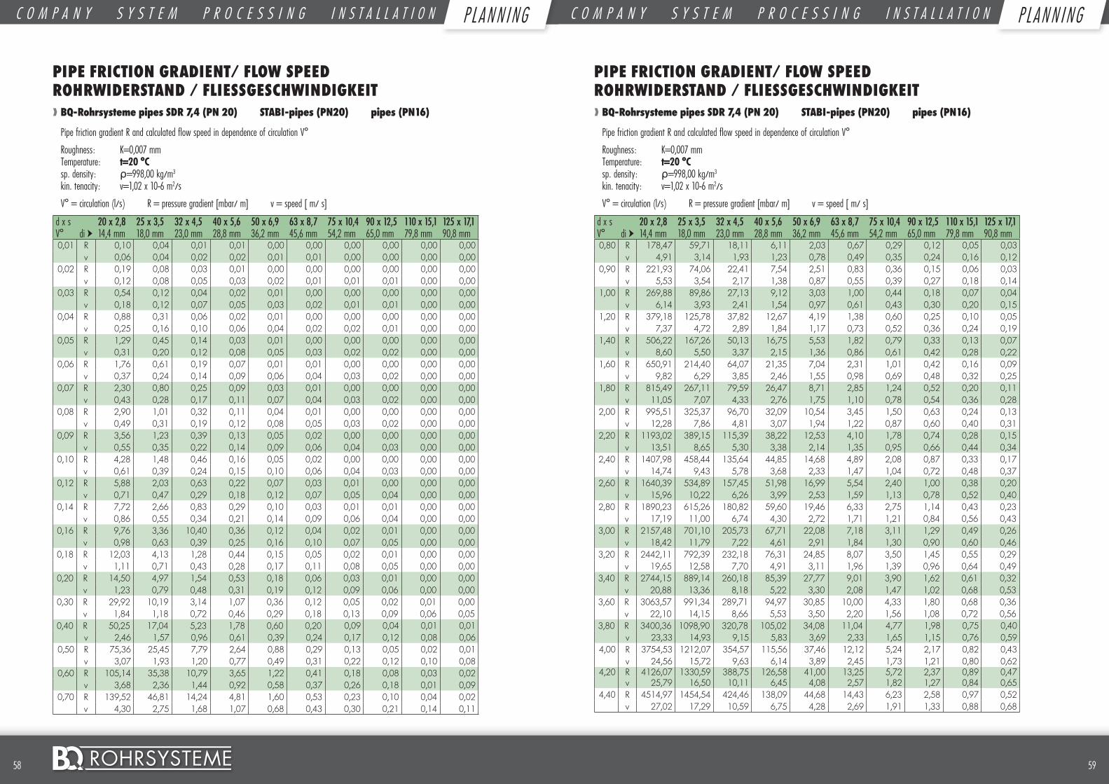
5958 ©
PIPE FRICTION GRADIENT/ FLOW SPEED ROHRWIDERSTAND / FLIESSGESCHWINDIGKEIT❱❱ BQ-Rohrsysteme pipes SDR 7,4 (PN 20) STABI-pipes (PN20) pipes (PN16)
Pipe friction gradient R and calculated flow speed in dependence of circulation V°
Roughness: K=0,007 mm Temperature: t=20 °C sp. density: ρ=998,00 kg/m3 kin. tenacity: v=1,02 x 10⁻⁶ m2/s
V° = circulation (l/s) R = pressure gradient [mbar/ m] v = speed [ m/ s]
d x s 20 x 2,8 25 x 3,5 32 x 4,5 40 x 5,6 50 x 6,9 63 x 8,7 75 x 10,4 90 x 12,5 110 x 15,1 125 x 17,1V° di ➤ 14,4 mm 18,0 mm 23,0 mm 28,8 mm 36,2 mm 45,6 mm 54,2 mm 65,0 mm 79,8 mm 90,8 mm0,01 R 0,10 0,04 0,01 0,01 0,00 0,00 0,00 0,00 0,00 0,00
v 0,06 0,04 0,02 0,02 0,01 0,01 0,00 0,00 0,00 0,000,02 R 0,19 0,08 0,03 0,01 0,00 0,00 0,00 0,00 0,00 0,00
v 0,12 0,08 0,05 0,03 0,02 0,01 0,01 0,01 0,00 0,000,03 R 0,54 0,12 0,04 0,02 0,01 0,00 0,00 0,00 0,00 0,00
v 0,18 0,12 0,07 0,05 0,03 0,02 0,01 0,01 0,00 0,000,04 R 0,88 0,31 0,06 0,02 0,01 0,00 0,00 0,00 0,00 0,00
v 0,25 0,16 0,10 0,06 0,04 0,02 0,02 0,01 0,00 0,000,05 R 1,29 0,45 0,14 0,03 0,01 0,00 0,00 0,00 0,00 0,00
v 0,31 0,20 0,12 0,08 0,05 0,03 0,02 0,02 0,00 0,000,06 R 1,76 0,61 0,19 0,07 0,01 0,01 0,00 0,00 0,00 0,00
v 0,37 0,24 0,14 0,09 0,06 0,04 0,03 0,02 0,00 0,000,07 R 2,30 0,80 0,25 0,09 0,03 0,01 0,00 0,00 0,00 0,00
v 0,43 0,28 0,17 0,11 0,07 0,04 0,03 0,02 0,00 0,000,08 R 2,90 1,01 0,32 0,11 0,04 0,01 0,00 0,00 0,00 0,00
v 0,49 0,31 0,19 0,12 0,08 0,05 0,03 0,02 0,00 0,000,09 R 3,56 1,23 0,39 0,13 0,05 0,02 0,00 0,00 0,00 0,00
v 0,55 0,35 0,22 0,14 0,09 0,06 0,04 0,03 0,00 0,000,10 R 4,28 1,48 0,46 0,16 0,05 0,02 0,00 0,00 0,00 0,00
v 0,61 0,39 0,24 0,15 0,10 0,06 0,04 0,03 0,00 0,000,12 R 5,88 2,03 0,63 0,22 0,07 0,03 0,01 0,00 0,00 0,00
v 0,71 0,47 0,29 0,18 0,12 0,07 0,05 0,04 0,00 0,000,14 R 7,72 2,66 0,83 0,29 0,10 0,03 0,01 0,01 0,00 0,00
v 0,86 0,55 0,34 0,21 0,14 0,09 0,06 0,04 0,00 0,000,16 R 9,76 3,36 10,40 0,36 0,12 0,04 0,02 0,01 0,00 0,00
v 0,98 0,63 0,39 0,25 0,16 0,10 0,07 0,05 0,00 0,000,18 R 12,03 4,13 1,28 0,44 0,15 0,05 0,02 0,01 0,00 0,00
v 1,11 0,71 0,43 0,28 0,17 0,11 0,08 0,05 0,00 0,000,20 R 14,50 4,97 1,54 0,53 0,18 0,06 0,03 0,01 0,00 0,00
v 1,23 0,79 0,48 0,31 0,19 0,12 0,09 0,06 0,00 0,000,30 R 29,92 10,19 3,14 1,07 0,36 0,12 0,05 0,02 0,01 0,00
v 1,84 1,18 0,72 0,46 0,29 0,18 0,13 0,09 0,06 0,050,40 R 50,25 17,04 5,23 1,78 0,60 0,20 0,09 0,04 0,01 0,01
v 2,46 1,57 0,96 0,61 0,39 0,24 0,17 0,12 0,08 0,060,50 R 75,36 25,45 7,79 2,64 0,88 0,29 0,13 0,05 0,02 0,01
v 3,07 1,93 1,20 0,77 0,49 0,31 0,22 0,12 0,10 0,080,60 R 105,14 35,38 10,79 3,65 1,22 0,41 0,18 0,08 0,03 0,02
v 3,68 2,36 1,44 0,92 0,58 0,37 0,26 0,18 0,01 0,090,70 R 139,52 46,81 14,24 4,81 1,60 0,53 0,23 0,10 0,04 0,02
v 4,30 2,75 1,68 1,07 0,68 0,43 0,30 0,21 0,14 0,11
PIPE FRICTION GRADIENT/ FLOW SPEED ROHRWIDERSTAND / FLIESSGESCHWINDIGKEIT❱❱ BQ-Rohrsysteme pipes SDR 7,4 (PN 20) STABI-pipes (PN20) pipes (PN16)
Pipe friction gradient R and calculated flow speed in dependence of circulation V°
Roughness: K=0,007 mm Temperature: t=20 °C sp. density: ρ=998,00 kg/m3 kin. tenacity: v=1,02 x 10⁻⁶ m2/s
V° = circulation (l/s) R = pressure gradient [mbar/ m] v = speed [ m/ s]
d x s 20 x 2,8 25 x 3,5 32 x 4,5 40 x 5,6 50 x 6,9 63 x 8,7 75 x 10,4 90 x 12,5 110 x 15,1 125 x 17,1V° di ➤ 14,4 mm 18,0 mm 23,0 mm 28,8 mm 36,2 mm 45,6 mm 54,2 mm 65,0 mm 79,8 mm 90,8 mm0,80 R 178,47 59,71 18,11 6,11 2,03 0,67 0,29 0,12 0,05 0,03
v 4,91 3,14 1,93 1,23 0,78 0,49 0,35 0,24 0,16 0,120,90 R 221,93 74,06 22,41 7,54 2,51 0,83 0,36 0,15 0,06 0,03
v 5,53 3,54 2,17 1,38 0,87 0,55 0,39 0,27 0,18 0,141,00 R 269,88 89,86 27,13 9,12 3,03 1,00 0,44 0,18 0,07 0,04
v 6,14 3,93 2,41 1,54 0,97 0,61 0,43 0,30 0,20 0,151,20 R 379,18 125,78 37,82 12,67 4,19 1,38 0,60 0,25 0,10 0,05
v 7,37 4,72 2,89 1,84 1,17 0,73 0,52 0,36 0,24 0,191,40 R 506,22 167,26 50,13 16,75 5,53 1,82 0,79 0,33 0,13 0,07
v 8,60 5,50 3,37 2,15 1,36 0,86 0,61 0,42 0,28 0,221,60 R 650,91 214,40 64,07 21,35 7,04 2,31 1,01 0,42 0,16 0,09
v 9,82 6,29 3,85 2,46 1,55 0,98 0,69 0,48 0,32 0,251,80 R 815,49 267,11 79,59 26,47 8,71 2,85 1,24 0,52 0,20 0,11
v 11,05 7,07 4,33 2,76 1,75 1,10 0,78 0,54 0,36 0,282,00 R 995,51 325,37 96,70 32,09 10,54 3,45 1,50 0,63 0,24 0,13
v 12,28 7,86 4,81 3,07 1,94 1,22 0,87 0,60 0,40 0,312,20 R 1193,02 389,15 115,39 38,22 12,53 4,10 1,78 0,74 0,28 0,15
v 13,51 8,65 5,30 3,38 2,14 1,35 0,95 0,66 0,44 0,342,40 R 1407,98 458,44 135,64 44,85 14,68 4,89 2,08 0,87 0,33 0,17
v 14,74 9,43 5,78 3,68 2,33 1,47 1,04 0,72 0,48 0,372,60 R 1640,39 534,89 157,45 51,98 16,99 5,54 2,40 1,00 0,38 0,20
v 15,96 10,22 6,26 3,99 2,53 1,59 1,13 0,78 0,52 0,402,80 R 1890,23 615,26 180,82 59,60 19,46 6,33 2,75 1,14 0,43 0,23
v 17,19 11,00 6,74 4,30 2,72 1,71 1,21 0,84 0,56 0,433,00 R 2157,48 701,10 205,73 67,71 22,08 7,18 3,11 1,29 0,49 0,26
v 18,42 11,79 7,22 4,61 2,91 1,84 1,30 0,90 0,60 0,463,20 R 2442,11 792,39 232,18 76,31 24,85 8,07 3,50 1,45 0,55 0,29
v 19,65 12,58 7,70 4,91 3,11 1,96 1,39 0,96 0,64 0,493,40 R 2744,15 889,14 260,18 85,39 27,77 9,01 3,90 1,62 0,61 0,32
v 20,88 13,36 8,18 5,22 3,30 2,08 1,47 1,02 0,68 0,533,60 R 3063,57 991,34 289,71 94,97 30,85 10,00 4,33 1,80 0,68 0,36
v 22,10 14,15 8,66 5,53 3,50 2,20 1,56 1,08 0,72 0,563,80 R 3400,36 1098,90 320,78 105,02 34,08 11,04 4,77 1,98 0,75 0,40
v 23,33 14,93 9,15 5,83 3,69 2,33 1,65 1,15 0,76 0,594,00 R 3754,53 1212,07 354,57 115,56 37,46 12,12 5,24 2,17 0,82 0,43
v 24,56 15,72 9,63 6,14 3,89 2,45 1,73 1,21 0,80 0,624,20 R 4126,07 1330,59 388,75 126,58 41,00 13,25 5,72 2,37 0,89 0,47
v 25,79 16,50 10,11 6,45 4,08 2,57 1,82 1,27 0,84 0,654,40 R 4514,97 1454,54 424,46 138,09 44,68 14,43 6,23 2,58 0,97 0,52
v 27,02 17,29 10,59 6,75 4,28 2,69 1,91 1,33 0,88 0,68
C O M P A N Y S Y S T E M P R O C E S S I N G I N S T A L L A T I O N P L A N N I N G C O M P A N Y S Y S T E M P R O C E S S I N G I N S T A L L A T I O N P L A N N I N GP L AN N I NG P L AN N I NG
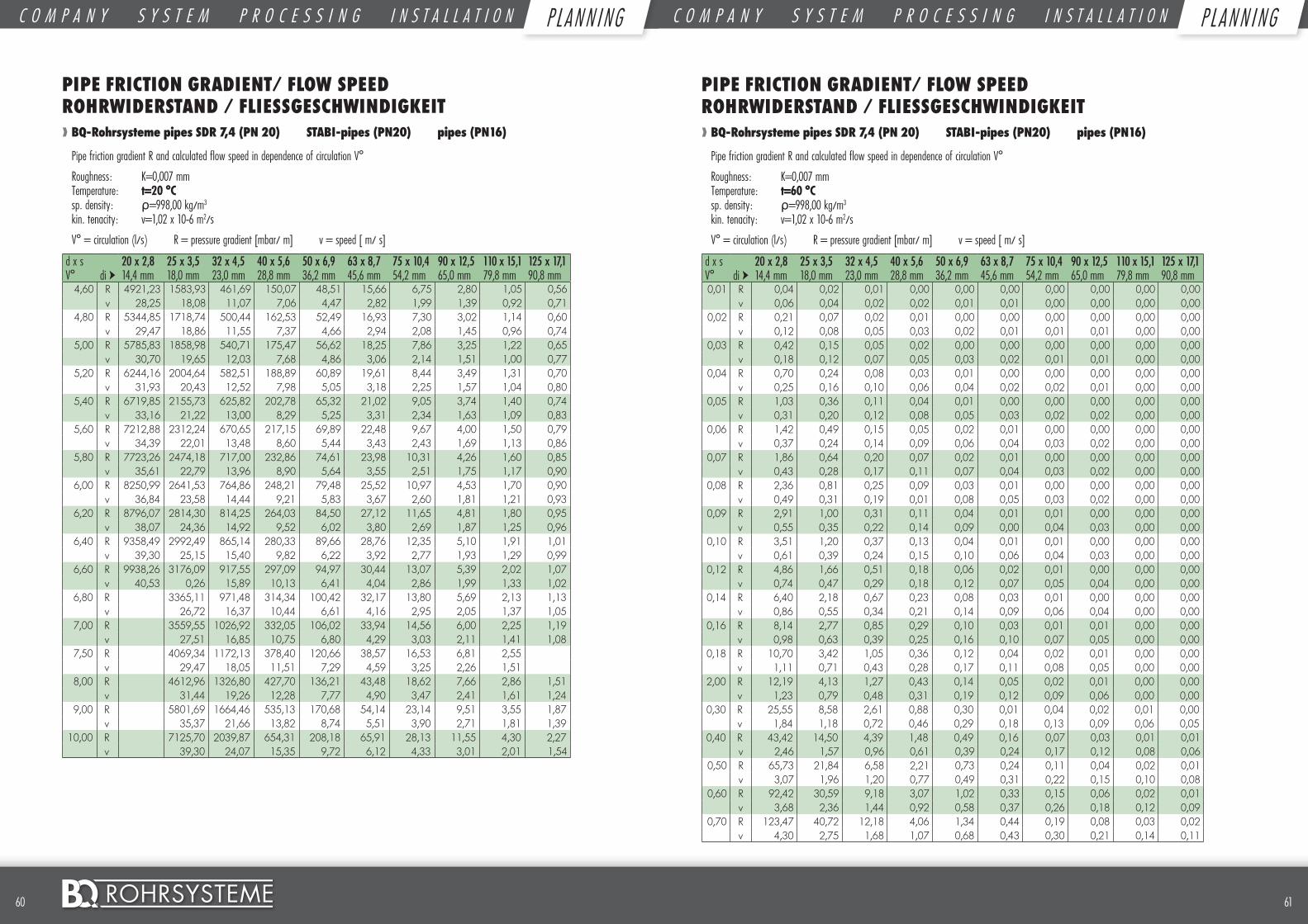
6160 ©
PIPE FRICTION GRADIENT/ FLOW SPEED ROHRWIDERSTAND / FLIESSGESCHWINDIGKEIT❱❱ BQ-Rohrsysteme pipes SDR 7,4 (PN 20) STABI-pipes (PN20) pipes (PN16)
Pipe friction gradient R and calculated flow speed in dependence of circulation V°
Roughness: K=0,007 mm Temperature: t=20 °C sp. density: ρ=998,00 kg/m3 kin. tenacity: v=1,02 x 10⁻⁶ m2/s
V° = circulation (l/s) R = pressure gradient [mbar/ m] v = speed [ m/ s]
d x s 20 x 2,8 25 x 3,5 32 x 4,5 40 x 5,6 50 x 6,9 63 x 8,7 75 x 10,4 90 x 12,5 110 x 15,1 125 x 17,1V° di ➤ 14,4 mm 18,0 mm 23,0 mm 28,8 mm 36,2 mm 45,6 mm 54,2 mm 65,0 mm 79,8 mm 90,8 mm
4,60 R 4921,23 1583,93 461,69 150,07 48,51 15,66 6,75 2,80 1,05 0,56v 28,25 18,08 11,07 7,06 4,47 2,82 1,99 1,39 0,92 0,71
4,80 R 5344,85 1718,74 500,44 162,53 52,49 16,93 7,30 3,02 1,14 0,60v 29,47 18,86 11,55 7,37 4,66 2,94 2,08 1,45 0,96 0,74
5,00 R 5785,83 1858,98 540,71 175,47 56,62 18,25 7,86 3,25 1,22 0,65v 30,70 19,65 12,03 7,68 4,86 3,06 2,14 1,51 1,00 0,77
5,20 R 6244,16 2004,64 582,51 188,89 60,89 19,61 8,44 3,49 1,31 0,70v 31,93 20,43 12,52 7,98 5,05 3,18 2,25 1,57 1,04 0,80
5,40 R 6719,85 2155,73 625,82 202,78 65,32 21,02 9,05 3,74 1,40 0,74v 33,16 21,22 13,00 8,29 5,25 3,31 2,34 1,63 1,09 0,83
5,60 R 7212,88 2312,24 670,65 217,15 69,89 22,48 9,67 4,00 1,50 0,79v 34,39 22,01 13,48 8,60 5,44 3,43 2,43 1,69 1,13 0,86
5,80 R 7723,26 2474,18 717,00 232,86 74,61 23,98 10,31 4,26 1,60 0,85v 35,61 22,79 13,96 8,90 5,64 3,55 2,51 1,75 1,17 0,90
6,00 R 8250,99 2641,53 764,86 248,21 79,48 25,52 10,97 4,53 1,70 0,90v 36,84 23,58 14,44 9,21 5,83 3,67 2,60 1,81 1,21 0,93
6,20 R 8796,07 2814,30 814,25 264,03 84,50 27,12 11,65 4,81 1,80 0,95v 38,07 24,36 14,92 9,52 6,02 3,80 2,69 1,87 1,25 0,96
6,40 R 9358,49 2992,49 865,14 280,33 89,66 28,76 12,35 5,10 1,91 1,01v 39,30 25,15 15,40 9,82 6,22 3,92 2,77 1,93 1,29 0,99
6,60 R 9938,26 3176,09 917,55 297,09 94,97 30,44 13,07 5,39 2,02 1,07v 40,53 0,26 15,89 10,13 6,41 4,04 2,86 1,99 1,33 1,02
6,80 R 3365,11 971,48 314,34 100,42 32,17 13,80 5,69 2,13 1,13v 26,72 16,37 10,44 6,61 4,16 2,95 2,05 1,37 1,05
7,00 R 3559,55 1026,92 332,05 106,02 33,94 14,56 6,00 2,25 1,19v 27,51 16,85 10,75 6,80 4,29 3,03 2,11 1,41 1,08
7,50 R 4069,34 1172,13 378,40 120,66 38,57 16,53 6,81 2,55v 29,47 18,05 11,51 7,29 4,59 3,25 2,26 1,51
8,00 R 4612,96 1326,80 427,70 136,21 43,48 18,62 7,66 2,86 1,51v 31,44 19,26 12,28 7,77 4,90 3,47 2,41 1,61 1,24
9,00 R 5801,69 1664,46 535,13 170,68 54,14 23,14 9,51 3,55 1,87v 35,37 21,66 13,82 8,74 5,51 3,90 2,71 1,81 1,39
10,00 R 7125,70 2039,87 654,31 208,18 65,91 28,13 11,55 4,30 2,27v 39,30 24,07 15,35 9,72 6,12 4,33 3,01 2,01 1,54
PIPE FRICTION GRADIENT/ FLOW SPEED ROHRWIDERSTAND / FLIESSGESCHWINDIGKEIT❱❱ BQ-Rohrsysteme pipes SDR 7,4 (PN 20) STABI-pipes (PN20) pipes (PN16)
Pipe friction gradient R and calculated flow speed in dependence of circulation V°
Roughness: K=0,007 mm Temperature: t=60 °C sp. density: ρ=998,00 kg/m3 kin. tenacity: v=1,02 x 10⁻⁶ m2/s
V° = circulation (l/s) R = pressure gradient [mbar/ m] v = speed [ m/ s]
d x s 20 x 2,8 25 x 3,5 32 x 4,5 40 x 5,6 50 x 6,9 63 x 8,7 75 x 10,4 90 x 12,5 110 x 15,1 125 x 17,1V° di ➤ 14,4 mm 18,0 mm 23,0 mm 28,8 mm 36,2 mm 45,6 mm 54,2 mm 65,0 mm 79,8 mm 90,8 mm0,01 R 0,04 0,02 0,01 0,00 0,00 0,00 0,00 0,00 0,00 0,00
v 0,06 0,04 0,02 0,02 0,01 0,01 0,00 0,00 0,00 0,000,02 R 0,21 0,07 0,02 0,01 0,00 0,00 0,00 0,00 0,00 0,00
v 0,12 0,08 0,05 0,03 0,02 0,01 0,01 0,01 0,00 0,000,03 R 0,42 0,15 0,05 0,02 0,00 0,00 0,00 0,00 0,00 0,00
v 0,18 0,12 0,07 0,05 0,03 0,02 0,01 0,01 0,00 0,000,04 R 0,70 0,24 0,08 0,03 0,01 0,00 0,00 0,00 0,00 0,00
v 0,25 0,16 0,10 0,06 0,04 0,02 0,02 0,01 0,00 0,000,05 R 1,03 0,36 0,11 0,04 0,01 0,00 0,00 0,00 0,00 0,00
v 0,31 0,20 0,12 0,08 0,05 0,03 0,02 0,02 0,00 0,000,06 R 1,42 0,49 0,15 0,05 0,02 0,01 0,00 0,00 0,00 0,00
v 0,37 0,24 0,14 0,09 0,06 0,04 0,03 0,02 0,00 0,000,07 R 1,86 0,64 0,20 0,07 0,02 0,01 0,00 0,00 0,00 0,00
v 0,43 0,28 0,17 0,11 0,07 0,04 0,03 0,02 0,00 0,000,08 R 2,36 0,81 0,25 0,09 0,03 0,01 0,00 0,00 0,00 0,00
v 0,49 0,31 0,19 0,01 0,08 0,05 0,03 0,02 0,00 0,000,09 R 2,91 1,00 0,31 0,11 0,04 0,01 0,01 0,00 0,00 0,00
v 0,55 0,35 0,22 0,14 0,09 0,00 0,04 0,03 0,00 0,000,10 R 3,51 1,20 0,37 0,13 0,04 0,01 0,01 0,00 0,00 0,00
v 0,61 0,39 0,24 0,15 0,10 0,06 0,04 0,03 0,00 0,000,12 R 4,86 1,66 0,51 0,18 0,06 0,02 0,01 0,00 0,00 0,00
v 0,74 0,47 0,29 0,18 0,12 0,07 0,05 0,04 0,00 0,000,14 R 6,40 2,18 0,67 0,23 0,08 0,03 0,01 0,00 0,00 0,00
v 0,86 0,55 0,34 0,21 0,14 0,09 0,06 0,04 0,00 0,000,16 R 8,14 2,77 0,85 0,29 0,10 0,03 0,01 0,01 0,00 0,00
v 0,98 0,63 0,39 0,25 0,16 0,10 0,07 0,05 0,00 0,000,18 R 10,70 3,42 1,05 0,36 0,12 0,04 0,02 0,01 0,00 0,00
v 1,11 0,71 0,43 0,28 0,17 0,11 0,08 0,05 0,00 0,002,00 R 12,19 4,13 1,27 0,43 0,14 0,05 0,02 0,01 0,00 0,00
v 1,23 0,79 0,48 0,31 0,19 0,12 0,09 0,06 0,00 0,000,30 R 25,55 8,58 2,61 0,88 0,30 0,01 0,04 0,02 0,01 0,00
v 1,84 1,18 0,72 0,46 0,29 0,18 0,13 0,09 0,06 0,050,40 R 43,42 14,50 4,39 1,48 0,49 0,16 0,07 0,03 0,01 0,01
v 2,46 1,57 0,96 0,61 0,39 0,24 0,17 0,12 0,08 0,060,50 R 65,73 21,84 6,58 2,21 0,73 0,24 0,11 0,04 0,02 0,01
v 3,07 1,96 1,20 0,77 0,49 0,31 0,22 0,15 0,10 0,080,60 R 92,42 30,59 9,18 3,07 1,02 0,33 0,15 0,06 0,02 0,01
v 3,68 2,36 1,44 0,92 0,58 0,37 0,26 0,18 0,12 0,090,70 R 123,47 40,72 12,18 4,06 1,34 0,44 0,19 0,08 0,03 0,02
v 4,30 2,75 1,68 1,07 0,68 0,43 0,30 0,21 0,14 0,11
C O M P A N Y S Y S T E M P R O C E S S I N G I N S T A L L A T I O N P L A N N I N G C O M P A N Y S Y S T E M P R O C E S S I N G I N S T A L L A T I O N P L A N N I N GP L AN N I NG P L AN N I NG
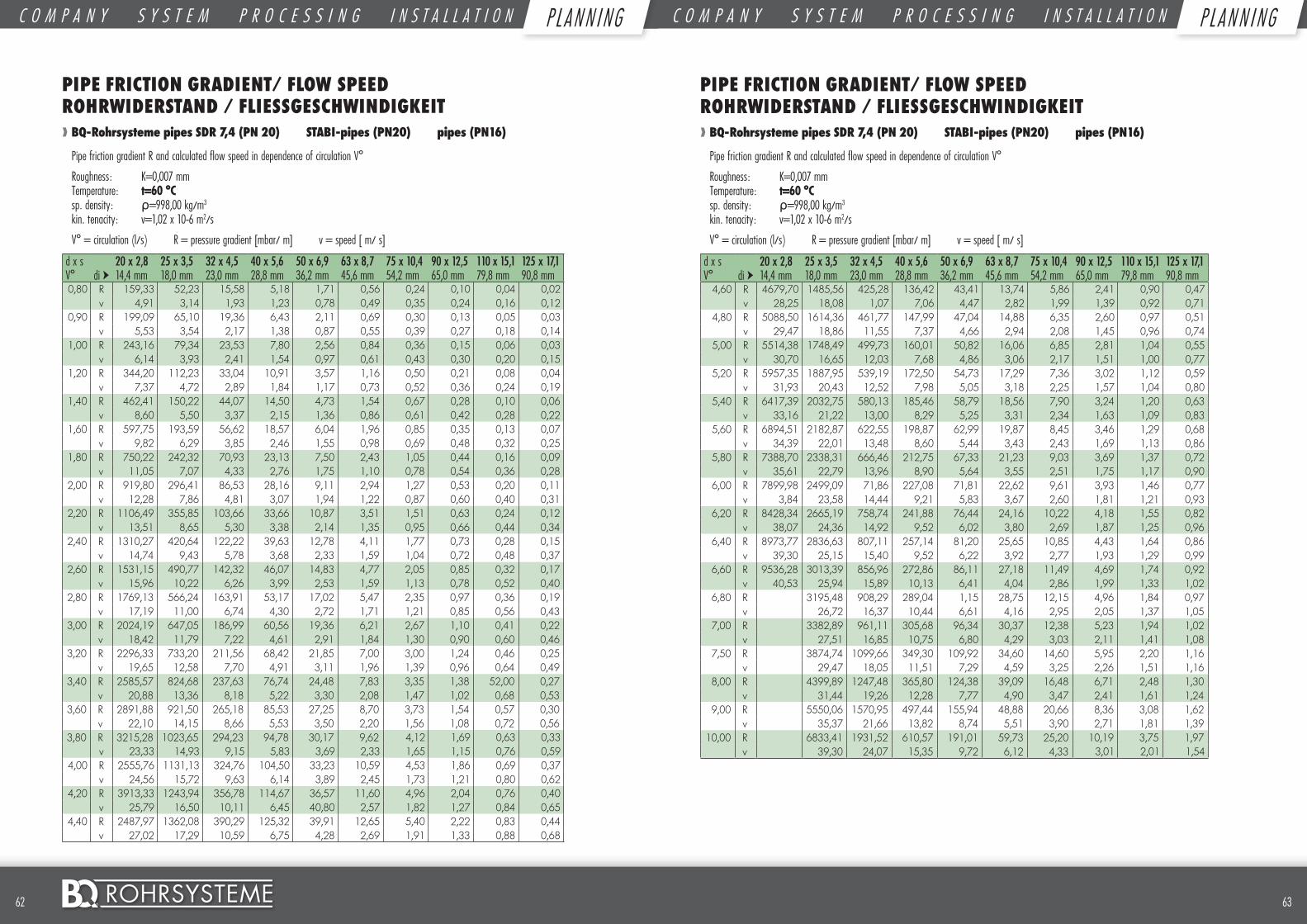
6362 ©
PIPE FRICTION GRADIENT/ FLOW SPEED ROHRWIDERSTAND / FLIESSGESCHWINDIGKEIT❱❱ BQ-Rohrsysteme pipes SDR 7,4 (PN 20) STABI-pipes (PN20) pipes (PN16)
Pipe friction gradient R and calculated flow speed in dependence of circulation V°
Roughness: K=0,007 mm Temperature: t=60 °C sp. density: ρ=998,00 kg/m3 kin. tenacity: v=1,02 x 10⁻⁶ m2/s
V° = circulation (l/s) R = pressure gradient [mbar/ m] v = speed [ m/ s]
d x s 20 x 2,8 25 x 3,5 32 x 4,5 40 x 5,6 50 x 6,9 63 x 8,7 75 x 10,4 90 x 12,5 110 x 15,1 125 x 17,1V° di ➤ 14,4 mm 18,0 mm 23,0 mm 28,8 mm 36,2 mm 45,6 mm 54,2 mm 65,0 mm 79,8 mm 90,8 mm0,80 R 159,33 52,23 15,58 5,18 1,71 0,56 0,24 0,10 0,04 0,02
v 4,91 3,14 1,93 1,23 0,78 0,49 0,35 0,24 0,16 0,120,90 R 199,09 65,10 19,36 6,43 2,11 0,69 0,30 0,13 0,05 0,03
v 5,53 3,54 2,17 1,38 0,87 0,55 0,39 0,27 0,18 0,141,00 R 243,16 79,34 23,53 7,80 2,56 0,84 0,36 0,15 0,06 0,03
v 6,14 3,93 2,41 1,54 0,97 0,61 0,43 0,30 0,20 0,151,20 R 344,20 112,23 33,04 10,91 3,57 1,16 0,50 0,21 0,08 0,04
v 7,37 4,72 2,89 1,84 1,17 0,73 0,52 0,36 0,24 0,191,40 R 462,41 150,22 44,07 14,50 4,73 1,54 0,67 0,28 0,10 0,06
v 8,60 5,50 3,37 2,15 1,36 0,86 0,61 0,42 0,28 0,221,60 R 597,75 193,59 56,62 18,57 6,04 1,96 0,85 0,35 0,13 0,07
v 9,82 6,29 3,85 2,46 1,55 0,98 0,69 0,48 0,32 0,251,80 R 750,22 242,32 70,93 23,13 7,50 2,43 1,05 0,44 0,16 0,09
v 11,05 7,07 4,33 2,76 1,75 1,10 0,78 0,54 0,36 0,282,00 R 919,80 296,41 86,53 28,16 9,11 2,94 1,27 0,53 0,20 0,11
v 12,28 7,86 4,81 3,07 1,94 1,22 0,87 0,60 0,40 0,312,20 R 1106,49 355,85 103,66 33,66 10,87 3,51 1,51 0,63 0,24 0,12
v 13,51 8,65 5,30 3,38 2,14 1,35 0,95 0,66 0,44 0,342,40 R 1310,27 420,64 122,22 39,63 12,78 4,11 1,77 0,73 0,28 0,15
v 14,74 9,43 5,78 3,68 2,33 1,59 1,04 0,72 0,48 0,372,60 R 1531,15 490,77 142,32 46,07 14,83 4,77 2,05 0,85 0,32 0,17
v 15,96 10,22 6,26 3,99 2,53 1,59 1,13 0,78 0,52 0,402,80 R 1769,13 566,24 163,91 53,17 17,02 5,47 2,35 0,97 0,36 0,19
v 17,19 11,00 6,74 4,30 2,72 1,71 1,21 0,85 0,56 0,433,00 R 2024,19 647,05 186,99 60,56 19,36 6,21 2,67 1,10 0,41 0,22
v 18,42 11,79 7,22 4,61 2,91 1,84 1,30 0,90 0,60 0,463,20 R 2296,33 733,20 211,56 68,42 21,85 7,00 3,00 1,24 0,46 0,25
v 19,65 12,58 7,70 4,91 3,11 1,96 1,39 0,96 0,64 0,493,40 R 2585,57 824,68 237,63 76,74 24,48 7,83 3,35 1,38 52,00 0,27
v 20,88 13,36 8,18 5,22 3,30 2,08 1,47 1,02 0,68 0,533,60 R 2891,88 921,50 265,18 85,53 27,25 8,70 3,73 1,54 0,57 0,30
v 22,10 14,15 8,66 5,53 3,50 2,20 1,56 1,08 0,72 0,563,80 R 3215,28 1023,65 294,23 94,78 30,17 9,62 4,12 1,69 0,63 0,33
v 23,33 14,93 9,15 5,83 3,69 2,33 1,65 1,15 0,76 0,594,00 R 2555,76 1131,13 324,76 104,50 33,23 10,59 4,53 1,86 0,69 0,37
v 24,56 15,72 9,63 6,14 3,89 2,45 1,73 1,21 0,80 0,624,20 R 3913,33 1243,94 356,78 114,67 36,57 11,60 4,96 2,04 0,76 0,40
v 25,79 16,50 10,11 6,45 40,80 2,57 1,82 1,27 0,84 0,654,40 R 2487,97 1362,08 390,29 125,32 39,91 12,65 5,40 2,22 0,83 0,44
v 27,02 17,29 10,59 6,75 4,28 2,69 1,91 1,33 0,88 0,68
PIPE FRICTION GRADIENT/ FLOW SPEED ROHRWIDERSTAND / FLIESSGESCHWINDIGKEIT❱❱ BQ-Rohrsysteme pipes SDR 7,4 (PN 20) STABI-pipes (PN20) pipes (PN16)
Pipe friction gradient R and calculated flow speed in dependence of circulation V°
Roughness: K=0,007 mm Temperature: t=60 °C sp. density: ρ=998,00 kg/m3 kin. tenacity: v=1,02 x 10⁻⁶ m2/s
V° = circulation (l/s) R = pressure gradient [mbar/ m] v = speed [ m/ s]
d x s 20 x 2,8 25 x 3,5 32 x 4,5 40 x 5,6 50 x 6,9 63 x 8,7 75 x 10,4 90 x 12,5 110 x 15,1 125 x 17,1V° di ➤ 14,4 mm 18,0 mm 23,0 mm 28,8 mm 36,2 mm 45,6 mm 54,2 mm 65,0 mm 79,8 mm 90,8 mm
4,60 R 4679,70 1485,56 425,28 136,42 43,41 13,74 5,86 2,41 0,90 0,47v 28,25 18,08 1,07 7,06 4,47 2,82 1,99 1,39 0,92 0,71
4,80 R 5088,50 1614,36 461,77 147,99 47,04 14,88 6,35 2,60 0,97 0,51v 29,47 18,86 11,55 7,37 4,66 2,94 2,08 1,45 0,96 0,74
5,00 R 5514,38 1748,49 499,73 160,01 50,82 16,06 6,85 2,81 1,04 0,55v 30,70 16,65 12,03 7,68 4,86 3,06 2,17 1,51 1,00 0,77
5,20 R 5957,35 1887,95 539,19 172,50 54,73 17,29 7,36 3,02 1,12 0,59v 31,93 20,43 12,52 7,98 5,05 3,18 2,25 1,57 1,04 0,80
5,40 R 6417,39 2032,75 580,13 185,46 58,79 18,56 7,90 3,24 1,20 0,63v 33,16 21,22 13,00 8,29 5,25 3,31 2,34 1,63 1,09 0,83
5,60 R 6894,51 2182,87 622,55 198,87 62,99 19,87 8,45 3,46 1,29 0,68v 34,39 22,01 13,48 8,60 5,44 3,43 2,43 1,69 1,13 0,86
5,80 R 7388,70 2338,31 666,46 212,75 67,33 21,23 9,03 3,69 1,37 0,72v 35,61 22,79 13,96 8,90 5,64 3,55 2,51 1,75 1,17 0,90
6,00 R 7899,98 2499,09 71,86 227,08 71,81 22,62 9,61 3,93 1,46 0,77v 3,84 23,58 14,44 9,21 5,83 3,67 2,60 1,81 1,21 0,93
6,20 R 8428,34 2665,19 758,74 241,88 76,44 24,16 10,22 4,18 1,55 0,82v 38,07 24,36 14,92 9,52 6,02 3,80 2,69 1,87 1,25 0,96
6,40 R 8973,77 2836,63 807,11 257,14 81,20 25,65 10,85 4,43 1,64 0,86v 39,30 25,15 15,40 9,52 6,22 3,92 2,77 1,93 1,29 0,99
6,60 R 9536,28 3013,39 856,96 272,86 86,11 27,18 11,49 4,69 1,74 0,92v 40,53 25,94 15,89 10,13 6,41 4,04 2,86 1,99 1,33 1,02
6,80 R 3195,48 908,29 289,04 1,15 28,75 12,15 4,96 1,84 0,97v 26,72 16,37 10,44 6,61 4,16 2,95 2,05 1,37 1,05
7,00 R 3382,89 961,11 305,68 96,34 30,37 12,38 5,23 1,94 1,02v 27,51 16,85 10,75 6,80 4,29 3,03 2,11 1,41 1,08
7,50 R 3874,74 1099,66 349,30 109,92 34,60 14,60 5,95 2,20 1,16v 29,47 18,05 11,51 7,29 4,59 3,25 2,26 1,51 1,16
8,00 R 4399,89 1247,48 365,80 124,38 39,09 16,48 6,71 2,48 1,30v 31,44 19,26 12,28 7,77 4,90 3,47 2,41 1,61 1,24
9,00 R 5550,06 1570,95 497,44 155,94 48,88 20,66 8,36 3,08 1,62v 35,37 21,66 13,82 8,74 5,51 3,90 2,71 1,81 1,39
10,00 R 6833,41 1931,52 610,57 191,01 59,73 25,20 10,19 3,75 1,97v 39,30 24,07 15,35 9,72 6,12 4,33 3,01 2,01 1,54
C O M P A N Y S Y S T E M P R O C E S S I N G I N S T A L L A T I O N P L A N N I N G C O M P A N Y S Y S T E M P R O C E S S I N G I N S T A L L A T I O N P L A N N I N GP L AN N I NG P L AN N I NG
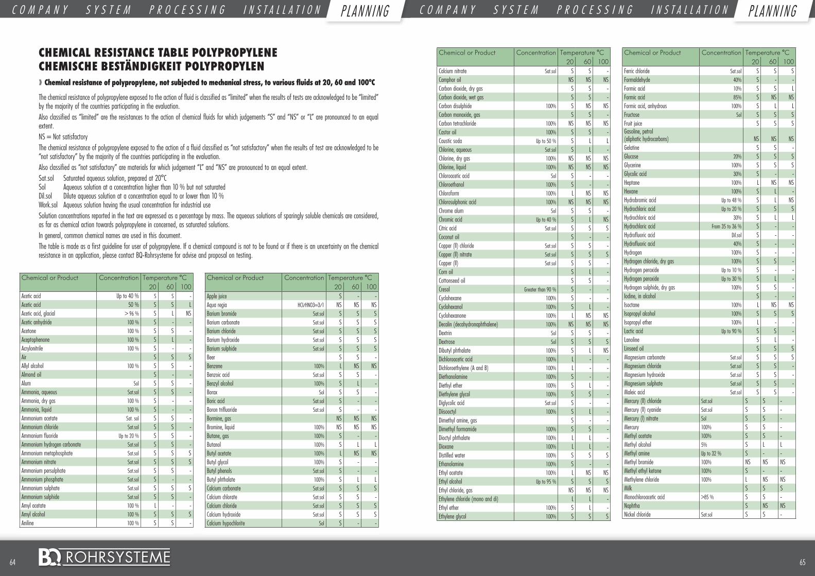
6564 ©
Chemical or Product Concentration Temperature °C20 60 100
Acetic acid Up to 40 % S S -Acetic acid 50 % S S LAcetic acid, glacial > 96 % S L NSAcetic anhydride 100 % S - -Acetone 100 % S S -Aceptophenone 100 % S L -Acrylonitrile 100 % S - -Air S S SAllyl alcohol 100 % S S -Almond oil S - -Alum Sol S S -Ammonia, aqueous Sat.sol S S -Ammonia, dry gas 100 % S - -Ammonia, liquid 100 % S - -Ammonium acetate Sat. sol S S -Ammonium chloride Sat.sol S S -Ammonium fluoride Up to 20 % S S -Ammonium hydrogen carbonate Sat.sol S S -Ammonium metaphosphate Sat.sol S S SAmmonium nitrate Sat.sol S S SAmmonium persulphate Sat.sol S S -Ammonium phosphate Sat.sol S - -Ammonium sulphate Sat.sol S S SAmmonium sulphide Sat.sol S S -Amyl acetate 100 % L - -Amyl alcohol 100 % S S SAniline 100 % S S -
Chemical or Product Concentration Temperature °C20 60 100
Apple juice S - -Aqua regia HCI/HNO3=3/1 NS NS NSBarium bromide Sat.sol S S SBarium carbonate Sat.sol S S SBarium chloride Sat.sol S S SBarium hydroxide Sat.sol S S SBarium sulphide Sat.sol S S SBeer S S -Benzene 100% L NS NSBenzoic acid Sat.sol S S -Benzyl alcohol 100% S L -Borax Sol S S -Boric acid Sat.sol S - -Boron trifluoride Sat.sol S - -Bormine, gas NS NS NSBromine, liquid 100% NS NS NSButane, gas 100% S - -Butanol 100% S L LButyl acetate 100% L NS NSButyl glycol 100% S - -Butyl phenols Sat.sol S - -Butyl phthalate 100% S L LCalcium carbonate Sat.sol S S SCalcium chlorate Sat.sol S S -Calcium chloride Sat.sol S S SCalcium hydroxide Sat.sol S S SCalcium hypochlorite Sol S - -
CHEMICAL RESISTANCE TABLE POLYPROPYLENE CHEMISCHE BESTÄNDIGKEIT POLYPROPYLEN❱❱ Chemical resistance of polypropylene, not subjected to mechanical stress, to various fluids at 20, 60 and 100°C
The chemical resistance of polypropylene exposed to the action of fluid is classified as “limited” when the results of tests are acknowledged to be “limited” by the majority of the countries participating in the evaluation.Also classified as “limited” are the resistances to the action of chemical fluids for which judgements “S” and “NS” or “L” are pronounced to an equal extent.NS = Not satisfactoryThe chemical resistance of polypropylene exposed to the action of a fluid classified as “not satisfactory” when the results of test are acknowledged to be “not satisfactory” by the majority of the countries participating in the evaluation.Also classified as “not satisfactory” are materials for which judgement “L” and “NS” are pronounced to an equal extent.Sat.sol Saturated aqueous solution, prepared at 20°C Sol Aqueous solution at a concentration higher than 10 % but not saturated Dil.sol Dilute aqueous solution at a concentration equal to or lower than 10 % Work.sol Aqueous solution having the usual concentration for industrial useSolution concentrations reported in the text are expressed as a percentage by mass. The aqueous solutions of sparingly soluble chemicals are considered, as far as chemical action towards polypropylene in concerned, as saturated solutions.In general, common chemical names are used in this document.The table is made as a first guideline for user of polypropylene. If a chemical compound is not to be found or if there is an uncertainty on the chemical resistance in an application, please contact BQ-Rohrsysteme for advise and proposal on testing.
Chemical or Product Concentration Temperature °C20 60 100
Calcium nitrate Sat.sol S S -Camphor oil NS NS NSCarbon dioxide, dry gas S S -Carbon dioxide, wet gas S S -Carbon disulphide 100% S NS NSCarbon monoxide, gas S S -Carbon tetrachloride 100% NS NS NSCastor oil 100% S S -Caustic soda Up to 50 % S L LChlorine, aqueous Sat.sol S L -Chlorine, dry gas 100% NS NS NSChlorine, liquid 100% NS NS NSChloroacetic acid Sol S - -Chloroethanol 100% S - -Chloroform 100% L NS NSChlorosulphonic acid 100% NS NS NSChrome alum Sol S S -Chromic acid Up to 40 % S L NSCitric acid Sat.sol S S SCoconut oil S - -Copper (ll) chloride Sat.sol S S -Copper (ll) nitrate Sat.sol S S SCopper (ll) Sat.sol S S -Corn oil S L -Cottonseed oil S S -Cresol Greater than 90 % S - -Cyclohexane 100% S - -Cyclohexanol 100% S L -Cyclohexanone 100% L NS NSDecalin (decahydronaphthalene) 100% NS NS NSDextrin Sol S S -Dextrose Sol S S SDibutyl phthalate 100% S L NSDichloroacetic acid 100% L - -Dichloroethylene (A and B) 100% L - -Diethanolamine 100% S - -Diethyl ether 100% S L -Diethylene glycol 100% S S -Diglycolic acid Sat.sol S - -Diisooctyl 100% S L -Dimethyl amine, gas S - -Dimethyl formamide 100% S S -Dioctyl phthalate 100% L L -Dioxane 100% L L -Distilled water 100% S S SEthanolamine 100% S - -Ethyl acetate 100% L NS NSEthyl alcohol Up to 95 % S S SEthyl chloride, gas NS NS NSEthylene chloride (mono and di) L L -Ethyl ether 100% S L -Ethylene glycol 100% S S S
Chemical or Product Concentration Temperature °C20 60 100
Ferric chloride Sat.sol S S SFormaldehyde 40% S - -Formic acid 10% S S LFormic acid 85% S NS NSFormic acid, anhydrous 100% S L LFructose Sol S S SFruit juice S S SGasoline, petrol (aliphatic hydrocarbons) NS NS NSGelatine S S -Glucose 20% S S SGlycerine 100% S S SGlycolic acid 30% S - -Heptane 100% L NS NSHexane 100% S L -Hydrobromic acid Up to 48 % S L NSHydrochloric acid Up to 20 % S S SHydrochloric acid 30% S L LHydrochloric acid From 35 to 36 % S - -Hydrofluoric acid Dil.sol S - -Hydrofluoric acid 40% S - -Hydrogen 100% S - -Hydrogen chloride, dry gas 100% S S -Hydrogen peroxide Up to 10 % S - -Hydrogen peroxide Up to 30 % S L -Hydrogen sulphide, dry gas 100% S S -Iodine, in alcohol S - -Isoctane 100% L NS NSIsopropyl alcohol 100% S S SIsopropyl ether 100% L - -Lactic acid Up to 90 % S S -Lanoline S L -Linseed oil S S SMagnesium carbonate Sat.sol S S SMagnesium chloride Sat.sol S S -Magnesium hydroxide Sat.sol S S -Magnesium sulphate Sat.sol S S -Maleic acid Sat.sol S S -Mercury (ll) chloride Sat.sol S S -Mercury (ll) cyanide Sat.sol S S -Mercury (l) nitrate Sol S S -Mercury 100% S S -Methyl acetate 100% S S -Methyl alcohol 5% S L LMethyl amine Up to 32 % S - -Methyl bromide 100% NS NS NSMethyl ethyl ketone 100% S - -Methylene chloride 100% L NS NSMilk S S SMonochloroacetic acid >85 % S S -Naphtha S NS NSNickel chloride Sat.sol S S -
C O M P A N Y S Y S T E M P R O C E S S I N G I N S T A L L A T I O N P L A N N I N G C O M P A N Y S Y S T E M P R O C E S S I N G I N S T A L L A T I O N P L A N N I N GP L AN N I NG P L AN N I NG
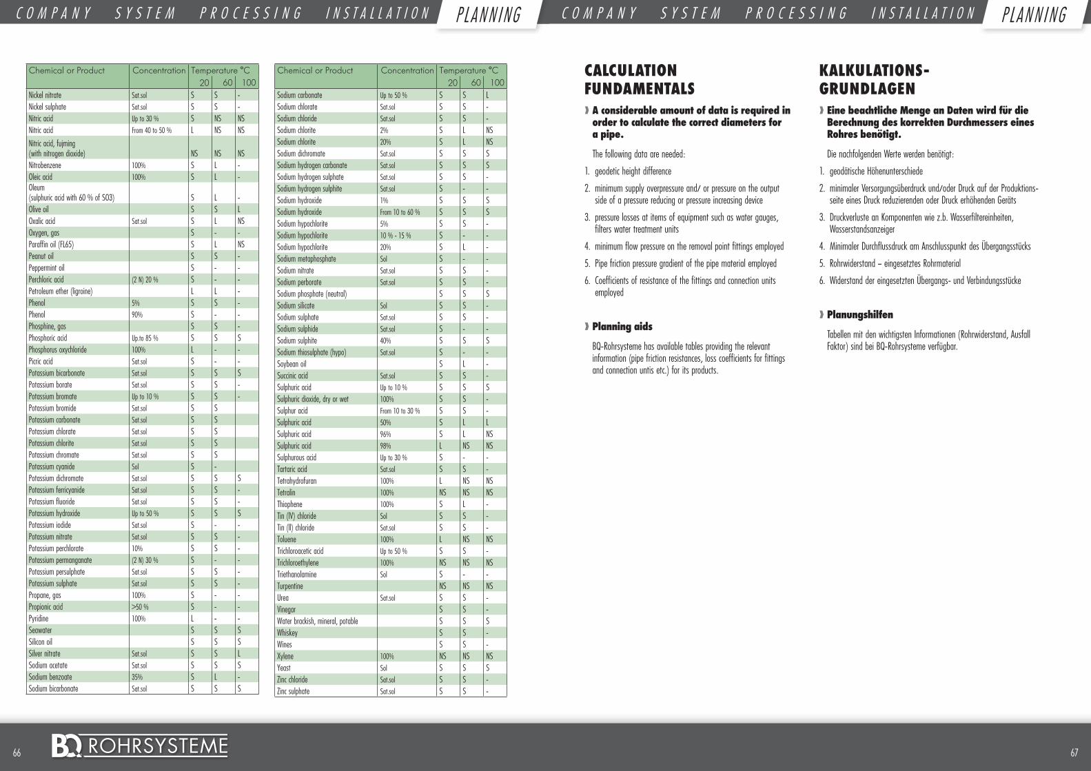
6766 ©
Chemical or Product Concentration Temperature °C20 60 100
Nickel nitrate Sat.sol S S -Nickel sulphate Sat.sol S S -Nitric acid Up to 30 % S NS NSNitric acid From 40 to 50 % L NS NSNitric acid, fujming (with nitrogen dioxide) NS NS NSNitrobenzene 100% S L -Oleic acid 100% S L -Oleum (sulphuric acid with 60 % of SO3) S L -Olive oil S S LOxalic acid Sat.sol S L NSOxygen, gas S - -Paraffin oil (FL65) S L NSPeanut oil S S -Peppermint oil S - -Perchloric acid (2 N) 20 % S - -Petroleum ether (ligroine) L L -Phenol 5% S S -Phenol 90% S - -Phosphine, gas S S -Phosphoric acid Up.to 85 % S S SPhosphorus oxychloride 100% L - -Picric acid Sat.sol S - -Potassium bicarbonate Sat.sol S S SPotassium borate Sat.sol S S -Potassium bromate Up to 10 % S S -Potassium bromide Sat.sol S SPotassium carbonate Sat.sol S SPotassium chlorate Sat.sol S SPotassium chlorite Sat.sol S SPotassium chromate Sat.sol S SPotassium cyanide Sol S -Potassium dichromate Sat.sol S S SPotassium ferricyanide Sat.sol S S -Potassium fluoride Sat.sol S S -Potassium hydroxide Up to 50 % S S SPotassium iodide Sat.sol S - -Potassium nitrate Sat.sol S S -Potassium perchlorate 10% S S -Potassium permanganate (2 N) 30 % S - -Potassium persulphate Sat.sol S S -Potassium sulphate Sat.sol S S -Propane, gas 100% S - -Propionic acid >50 % S - -Pyridine 100% L - -Seawater S S SSilicon oil S S SSilver nitrate Sat.sol S S LSodium acetate Sat.sol S S SSodium benzoate 35% S L -Sodium bicarbonate Sat.sol S S S
Chemical or Product Concentration Temperature °C20 60 100
Sodium carbonate Up to 50 % S S LSodium chlorate Sat.sol S S -Sodium chloride Sat.sol S S -Sodium chlorite 2% S L NSSodium chlorite 20% S L NSSodium dichromate Sat.sol S S SSodium hydrogen carbonate Sat.sol S S SSodium hydrogen sulphate Sat.sol S S -Sodium hydrogen sulphite Sat.sol S - -Sodium hydroxide 1% S S SSodium hydroxide From 10 to 60 % S S SSodium hypochlorite 5% S S -Sodium hypochlorite 10 % - 15 % S - -Sodium hypochlorite 20% S L -Sodium metaphosphate Sol S - -Sodium nitrate Sat.sol S S -Sodium perborate Sat.sol S S -Sodium phosphate (neutral) S S SSodium silicate Sol S S -Sodium sulphate Sat.sol S S -Sodium sulphide Sat.sol S - -Sodium sulphite 40% S S SSodium thiosulphate (hypo) Sat.sol S - -Soybean oil S L -Succinic acid Sat.sol S S -Sulphuric acid Up to 10 % S S SSulphuric dioxide, dry or wet 100% S S -Sulphur acid From 10 to 30 % S S -Sulphuric acid 50% S L LSulphuric acid 96% S L NSSulphuric acid 98% L NS NSSulphurous acid Up to 30 % S - -Tartaric acid Sat.sol S S -Tetrahydrofuran 100% L NS NSTetralin 100% NS NS NSThiophene 100% S L -Tin (lV) chloride Sol S S -Tin (ll) chloride Sat.sol S S -Toluene 100% L NS NSTrichloroacetic acid Up to 50 % S S -Trichloroethylene 100% NS NS NSTriethanolamine Sol S - -Turpentine NS NS NSUrea Sat.sol S S -Vinegar S S -Water brackish, mineral, potable S S SWhiskey S S -Wines S S -Xylene 100% NS NS NSYeast Sol S S SZinc chloride Sat.sol S S -Zinc sulphate Sat.sol S S -
CALCULATION FUNDAMENTALS❱❱ A considerable amount of data is required in order to calculate the correct diameters for a pipe.
The following data are needed:
1. geodetic height difference
2. minimum supply overpressure and/ or pressure on the output side of a pressure reducing or pressure increasing device
3. pressure losses at items of equipment such as water gauges, filters water treatment units
4. minimum flow pressure on the removal point fittings employed
5. Pipe friction pressure gradient of the pipe material employed
6. Coefficients of resistance of the fittings and connection units employed
❱❱ Planning aids
BQ-Rohrsysteme has available tables providing the relevant information (pipe friction resistances, loss coefficients for fittings and connection untis etc.) for its products.
KALKULATIONS- GRUNDLAGEN❱❱ Eine beachtliche Menge an Daten wird für die Berechnung des korrekten Durchmessers eines Rohres benötigt.
Die nachfolgenden Werte werden benötigt:
1. geodätische Höhenunterschiede
2. minimaler Versorgungsüberdruck und/oder Druck auf der Produktions-seite eines Druck reduzierenden oder Druck erhöhenden Geräts
3. Druckverluste an Komponenten wie z.b. Wasserfiltereinheiten, Wasserstandsanzeiger
4. Minimaler Durchflussdruck am Anschlusspunkt des Übergangsstücks
5. Rohrwiderstand – eingesetztes Rohrmaterial
6. Widerstand der eingesetzten Übergangs- und Verbindungsstücke
❱❱ Planungshilfen
Tabellen mit den wichtigsten Informationen (Rohrwiderstand, Ausfall Faktor) sind bei BQ-Rohrsysteme verfügbar.
C O M P A N Y S Y S T E M P R O C E S S I N G I N S T A L L A T I O N P L A N N I N G C O M P A N Y S Y S T E M P R O C E S S I N G I N S T A L L A T I O N P L A N N I N GP L AN N I NG P L AN N I NG
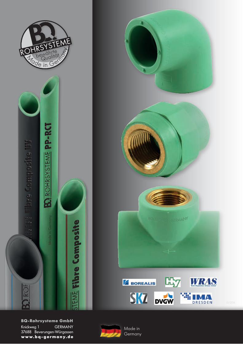
©
©
©M
ade
in G
erm
any
M
ade in German
yQualitätbewährte
©
Made in Germany
01/2016
BQ-Rohrsysteme GmbH Knickweg 1 GERMANY 37688 Beverungen-Würgassen www.bq-germany.de