powerbook 165c/180c - tim.id.autim.id.au/laptops/apple/powerbook/powerbook_165c.180c.pdf ·...
TRANSCRIPT
Service Source
K
PowerBook 165c/180c
PowerBook 165c, PowerBook 180c
Service Source
K
Basics
PowerBook 165c/180c

Basics Overview - 1
Overview
This manual includes complete repair procedures for the PowerBook 165C and PowerBook 180C, shown at left.
Figure: PowerBook 165C, 180C

Basics Repair Strategy - 2
Repair Strategy
Service the PowerBook 165c and PowerBook180c through module exchange and parts replacement. Customers can request on-site service from an Apple Authorized Service Provider Plus (AASP+) Apple Assurance (US only), or request a courier through the Apple Canada Technical Answerline (Canada only). They can also choose carry-in service from an AASP.
Ordering
Apple Service Providers planning to support the computer systems covered in this manual may purchase Service modules and parts to develop servicing capability. To order parts, use the AppleOrder (US only) or ARIS (Canada only) system and refer to “Service Price Pages.”

Basics Repair Strategy - 3
Large businesses, universities, and K-12 accounts must provide a purchase order on all transactions, including orders placed through the AppleOrder (US only) or ARIS (Canada only) system.
USA Ordering
US Service Providers not enrolled in AppleOrder may fax their orders to Service Provider Support (512-908-8125) or mail them to
Apple Computer, Inc.Service Provider SupportMS 212-SPSAustin, TX 78714-9125
For US inquiries, please call Service Provider Support at 800-919-2775 and select option #1.
Basics Repair Strategy - 4
Canadian Ordering
Canadian Service Providers not enrolled in ARIS may fax their orders to Service Provider Support in Canada (1-800-903-5284). For Canadian inquiries, please call Service Provider Support at 905-513-5782 and select option #3.
Basics Warranty/AppleCare/ARIS - 5
Warranty/AppleCare/ARIS
US Only
The PowerBook 165c and PowerBook180c are covered under the Apple One-Year Limited Warranty. The AppleCare Service Plan is also available for these products. Service Providers are reimbursed for warranty and AppleCare repairs made to these computers. For pricing information, refer to “Service Price Pages.”
Canada Only
The PowerBook 165c and PowerBook180c are covered under first-year AppleCare. The Extended AppleCare Service Plan is also available for these products. Service Providers are reimbursed for first-year warranty and Extended AppleCare repairs made to these computers. For pricing information, refer to “Service Price Pages.”

Basics Display Compatibility Matrix - 6
Display Compatibility Matrix
Important:
The PowerBook 165c/180c family includes two displays—an active matrix and an FSTN display. Each of these displays requires a compatible inverter and display cable; the inverters, display cables, and displays are not interchangeable. Before ordering one of these parts, refer to the display matrix shown above.
FSTNPowerBook 165c661-0752
Active MatrixPowerBook 180c661-0686
Inverter 922-0374 922-0378
Display Cable 922-0373 922-0380
Inverter Cable 922-0566 922-0412
Service Source
K
Specifications
PowerBook 165c/180c
Specifications Introduction - 2
Introduction
Specifications information for this product can be found in this chapter and also in the Spec Database, which you can access in one of three ways:• Launch it directly by double-clicking the Apple Spec Database
runtime alias at the top level of the Main Service Source CD.• Select “Apple Spec Database” from the Service Source drop-
down main menu.• Click the Acrobat toolbar icon for the database, which is near
the right end of the toolbar with the letters “SP.”
Specifications Configurations - 3
Configurations
Standard 165c
4 MB PSRAM, FSTN color display, 80/120 MB hard drive, 1.4 MB Apple SuperDrive, NiCad battery, AC adapter, and microphone
Standard 180c
4 MB PSRAM, 8.4 in (226 mm) diagonal backlit color active-matrix LCD display, 80 or 160 MB hard drive, 1.4 MB Apple SuperDrive, NiCad battery, AC adapter, and microphone
Options
Internal PowerBook Express Modem (14,400 bps)Internal PowerBook Fax/Data Modem (2400 bps)4 MB memory expansion kitPowerBook battery rechargerHDI-30 SCSI system cableHDI-30 SCSI disk adapter
Specifications Processor - 4
Processor
CPU
Motorola 68030 microprocessor33 MHz
Coprocessor
Motorola 68882 floating-point math coprocessor33 MHz
Addressing
32-bit internal registers32-bit address bus32-bit data bus
Specifications Memory - 5
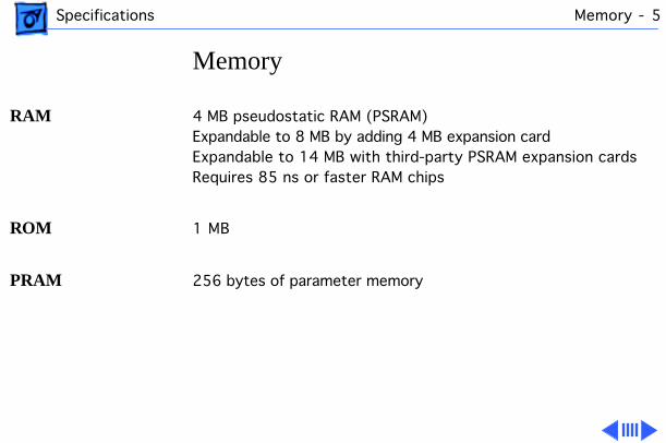
Memory
RAM
4 MB pseudostatic RAM (PSRAM) Expandable to 8 MB by adding 4 MB expansion cardExpandable to 14 MB with third-party PSRAM expansion cardsRequires 85 ns or faster RAM chips
ROM
1 MB
PRAM
256 bytes of parameter memory
Specifications Memory - 6
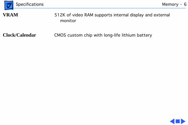
VRAM
512K of video RAM supports internal display and external monitor
Clock/Calendar
CMOS custom chip with long-life lithium battery
Specifications Disk Storage - 7
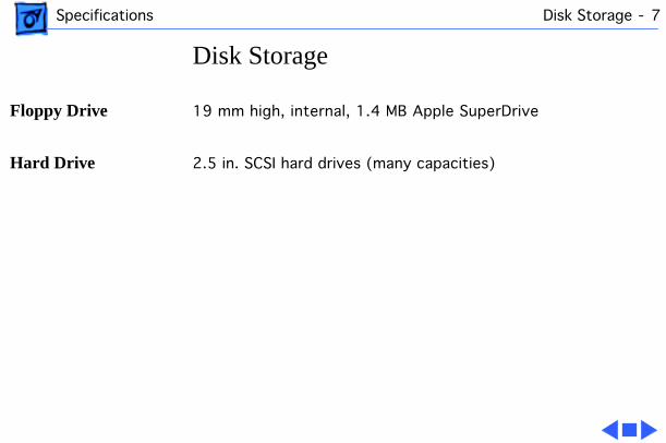
Disk Storage
Floppy Drive
19 mm high, internal, 1.4 MB Apple SuperDrive
Hard Drive
2.5 in. SCSI hard drives (many capacities)
Specifications I/O Interfaces - 8
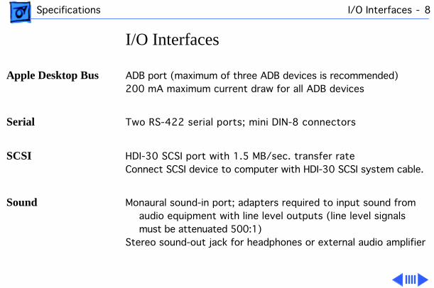
I/O Interfaces
Apple Desktop Bus
ADB port (maximum of three ADB devices is recommended)200 mA maximum current draw for all ADB devices
Serial
Two RS-422 serial ports; mini DIN-8 connectors
SCSI
HDI-30 SCSI port with 1.5 MB/sec. transfer rateConnect SCSI device to computer with HDI-30 SCSI system cable.
Sound
Monaural sound-in port; adapters required to input sound from audio equipment with line level outputs (line level signals must be attenuated 500:1)
Stereo sound-out jack for headphones or external audio amplifier
Specifications I/O Interfaces - 9
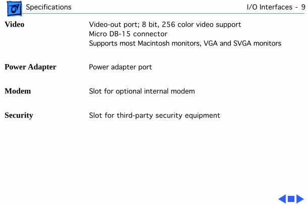
Video
Video-out port; 8 bit, 256 color video supportMicro DB-15 connectorSupports most Macintosh monitors, VGA and SVGA monitors
Power Adapter
Power adapter port
Modem
Slot for optional internal modem
Security
Slot for third-party security equipment
Specifications I/O Devices - 10
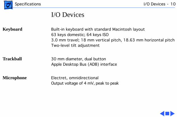
I/O Devices
Keyboard
Built-in keyboard with standard Macintosh layout63 keys domestic; 64 keys ISO3.0 mm travel; 18 mm vertical pitch, 18.63 mm horizontal pitchTwo-level tilt adjustment
Trackball
30 mm diameter, dual buttonApple Desktop Bus (ADB) interface
Microphone
Electret, omnidirectionalOutput voltage of 4 mV, peak to peak
Specifications Sound and Video - 11
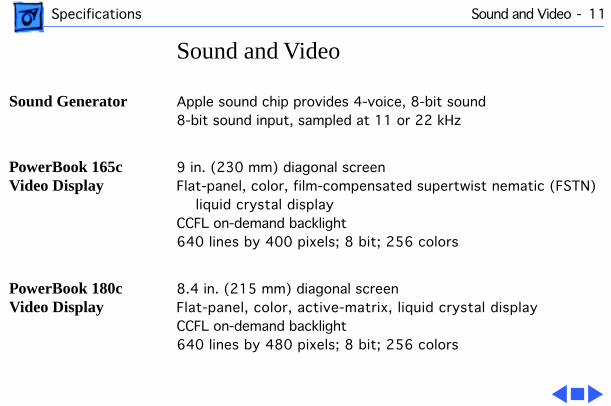
Sound and Video
Sound Generator
Apple sound chip provides 4-voice, 8-bit sound 8-bit sound input, sampled at 11 or 22 kHz
PowerBook 165c Video Display
9 in. (230 mm) diagonal screenFlat-panel, color, film-compensated supertwist nematic (FSTN)
liquid crystal displayCCFL on-demand backlight640 lines by 400 pixels; 8 bit; 256 colors
PowerBook 180c Video Display
8.4 in. (215 mm) diagonal screenFlat-panel, color, active-matrix, liquid crystal displayCCFL on-demand backlight640 lines by 480 pixels; 8 bit; 256 colors
Specifications Electrical - 12
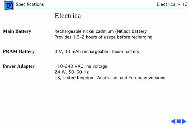
Electrical
Main Battery
Rechargeable nickel cadmium (NiCad) batteryProvides 1.5–2 hours of usage before recharging
PRAM Battery
3 V, 30 mAh rechargeable lithium battery
Power Adapter
110–240 VAC line voltage24 W, 50–60 HzUS, United Kingdom, Australian, and European versions

Specifications Physical - 13
Physical
PowerBook 165c
Height: 2.29 in. (58 mm)Width: 11.26 in. (286 mm)Depth: 9.29 in. (236 mm)Weight: 7.0 lb. (3.18 kg) with battery
PowerBook 180c
Height: 2.34 in. (59 mm)Width: 11.25 in. (286 mm)Depth: 9.3 in. (236 mm)Weight: 7.1 lb. (3.2 kg) with battery
Specifications Environmental - 14
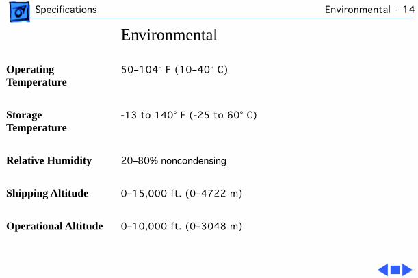
Environmental
Operating Temperature
50–104° F (10–40° C)
Storage Temperature
-13 to 140° F (-25 to 60° C)
Relative Humidity
20–80% noncondensing
Shipping Altitude
0–15,000 ft. (0–4722 m)
Operational Altitude
0–10,000 ft. (0–3048 m)
Specifications Other - 15
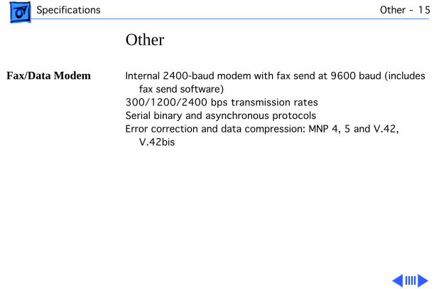
Other
Fax/Data Modem
Internal 2400-baud modem with fax send at 9600 baud (includes fax send software)
300/1200/2400 bps transmission ratesSerial binary and asynchronous protocolsError correction and data compression: MNP 4, 5 and V.42,
V.42bis
Specifications Other - 16
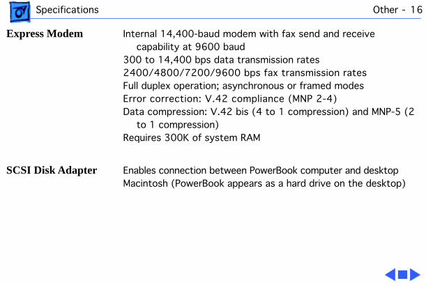
Express Modem
Internal 14,400-baud modem with fax send and receive capability at 9600 baud
300 to 14,400 bps data transmission rates2400/4800/7200/9600 bps fax transmission ratesFull duplex operation; asynchronous or framed modesError correction: V.42 compliance (MNP 2-4)Data compression: V.42 bis (4 to 1 compression) and MNP-5 (2
to 1 compression)Requires 300K of system RAM
SCSI Disk Adapter
Enables connection between PowerBook computer and desktop Macintosh (PowerBook appears as a hard drive on the desktop)
Service Source
K
Troubleshooting
PowerBook 165c/180c
Troubleshooting General/ - 1
General
The Symptom Charts included in this chapter will help you diagnose specific symptoms related to your product. Because cures are listed on the charts in the order of most likely solution, try the first cure first. Verify whether or not the product continues to exhibit the symptom. If the symptom persists, try the next cure. (Note: If you have replaced a module, reinstall the original module before you proceed to the next cure.)
If you are not sure what the problem is, or if the Symptom Charts do not resolve the problem, refer to the Flowchart for the product family.
For additional assistance, contact Apple Technical Support.
Troubleshooting Symptom Charts/Startup - 2
Symptom Charts
Startup
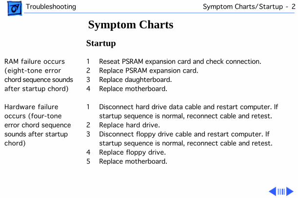
RAM failure occurs (eight-tone error chord sequence sounds after startup chord)
1 Reseat PSRAM expansion card and check connection.2 Replace PSRAM expansion card.3 Replace daughterboard.4 Replace motherboard.
Hardware failure occurs (four-tone error chord sequence sounds after startup chord)
1 Disconnect hard drive data cable and restart computer. If startup sequence is normal, reconnect cable and retest.
2 Replace hard drive.3 Disconnect floppy drive cable and restart computer. If
startup sequence is normal, reconnect cable and retest.4 Replace floppy drive.5 Replace motherboard.
Troubleshooting Symptom Charts/Startup - 3
Startup
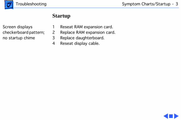
Screen displays checkerboard pattern; no startup chime
1 Reseat RAM expansion card.2 Replace RAM expansion card.3 Replace daughterboard.4 Reseat display cable.

Troubleshooting Symptom Charts/Power - 4
Power
Screen is blank; computer doesn’t respond
1 Restart computer.2 Connect power adapter and restart computer in 3–4 minutes.3 Try known-good, charged main battery.4 Check all interconnect board, daughterboard, and
motherboard connections.5 Reset the power manager.6 Replace keyboard.7 Replace interconnect board.8 Replace daughterboard.9 Replace motherboard.10 PowerBook165c: Replace display.11 PowerBook180c: Replace display (CPRC/international
repairers only).
Troubleshooting Symptom Charts/Power - 5
Power
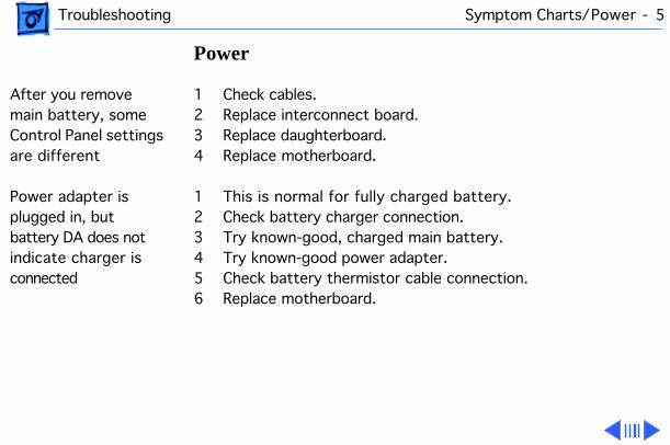
After you remove main battery, some Control Panel settings are different
1 Check cables.2 Replace interconnect board.3 Replace daughterboard.4 Replace motherboard.
Power adapter is plugged in, but battery DA does not indicate charger is connected
1 This is normal for fully charged battery.2 Check battery charger connection.3 Try known-good, charged main battery.4 Try known-good power adapter.5 Check battery thermistor cable connection.6 Replace motherboard.
Troubleshooting Symptom Charts/Power - 6
Power
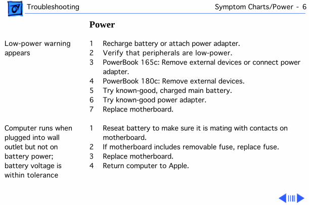
Low-power warning appears
1 Recharge battery or attach power adapter.2 Verify that peripherals are low-power.3 PowerBook 165c: Remove external devices or connect power
adapter.4 PowerBook 180c: Remove external devices. 5 Try known-good, charged main battery.6 Try known-good power adapter.7 Replace motherboard.
Computer runs when plugged into wall outlet but not on battery power; battery voltage is within tolerance
1 Reseat battery to make sure it is mating with contacts on motherboard.
2 If motherboard includes removable fuse, replace fuse.3 Replace motherboard.4 Return computer to Apple.
Troubleshooting Symptom Charts/Power - 7
Power
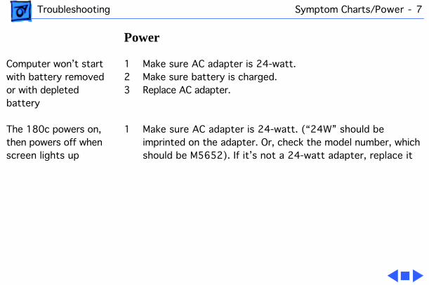
Computer won’t start with battery removed or with depleted battery
1 Make sure AC adapter is 24-watt.2 Make sure battery is charged.3 Replace AC adapter.
The 180c powers on, then powers off when screen lights up
1 Make sure AC adapter is 24-watt. (“24W” should be imprinted on the adapter. Or, check the model number, which should be M5652). If it’s not a 24-watt adapter, replace it

Troubleshooting Symptom Charts/Video - 8
Video
Row or partial row of pixels never comes on or is always on
PowerBook 165c:
1 Check cables.2 Replace display cable.3 Replace display. 4 Replace interconnect board.
PowerBook 180c:
5 Check cables.6 Replace display cable.7 Replace interconnect board. 8 Replace display (CPRC/international repairers only).
Troubleshooting Symptom Charts/Video - 9
Video
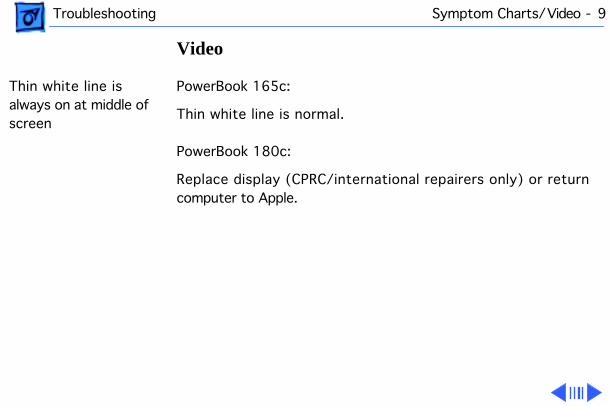
Thin white line is always on at middle of screen
PowerBook 165c:
Thin white line is normal.
PowerBook 180c:
Replace display (CPRC/international repairers only) or return computer to Apple.
Troubleshooting Symptom Charts/Video - 10
Video
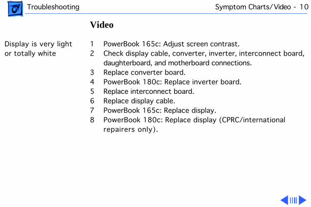
Display is very light or totally white
1 PowerBook 165c: Adjust screen contrast.2 Check display cable, converter, inverter, interconnect board,
daughterboard, and motherboard connections.3 Replace converter board.4 PowerBook 180c: Replace inverter board.5 Replace interconnect board.6 Replace display cable.7 PowerBook 165c: Replace display. 8 PowerBook 180c: Replace display (CPRC/international
repairers only).
Troubleshooting Symptom Charts/Video - 11
Video
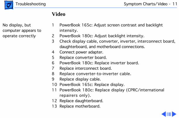
No display, but computer appears to operate correctly
1 PowerBook 165c: Adjust screen contrast and backlight intensity.
2 PowerBook 180c: Adjust backlight intensity.3 Check display cable, converter, inverter, interconnect board,
daughterboard, and motherboard connections.4 Connect power adapter.5 Replace converter board.6 PowerBook 180c: Replace inverter board.7 Replace interconnect board.8 Replace converter-to-inverter cable.9 Replace display cable.10 PowerBook 165c: Replace display.11 PowerBook 180c: Replace display (CPRC/international
repairers only).12 Replace daughterboard.13 Replace motherboard.
Troubleshooting Symptom Charts/Video - 12
Video
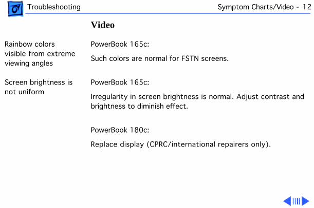
Rainbow colors visible from extreme viewing angles
PowerBook 165c:
Such colors are normal for FSTN screens.
Screen brightness is not uniform
PowerBook 165c:
Irregularity in screen brightness is normal. Adjust contrast and brightness to diminish effect.
PowerBook 180c:
Replace display (CPRC/international repairers only).
Troubleshooting Symptom Charts/Video - 13
Video
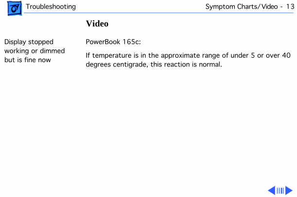
Display stopped working or dimmed but is fine now
PowerBook 165c:
If temperature is in the approximate range of under 5 or over 40 degrees centigrade, this reaction is normal.

Troubleshooting Symptom Charts/Video - 14
Video
Backlight doesn’t operate
1 Verify that cables are not pinched or severed.2 Check display cable, converter, inverter, interconnect board,
daughterboard, and motherboard connections.3 Replace converter board.4 PowerBook 180c: Replace inverter board.5 Replace converter-to-inverter cable.6 Replace interconnect board.7 PowerBook 165c: Replace display. 8 Replace daughterboard.9 Replace motherboard.10 PowerBook 180c: Replace display (CPRC/international
repairers only).
Troubleshooting Symptom Charts/Video - 15
Video
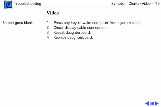
Screen goes blank 1 Press any key to wake computer from system sleep.2 Check display cable connection.3 Reseat daughterboard.4 Replace daughterboard.
Troubleshooting Symptom Charts/Video - 16
Video
Pixel is always white or always black
PowerBook 180c: In general, no display should be replaced because of subpixel irregularities. If the number of irregularities on a display appears excessive, contact Apple for more information.
Note: Each pixel on an active-matrix color display consists of three subpixels (red, green, and blue). In turn, each subpixel has a transistor that controls light transmission. A PowerBook 180c display, therefore, contains a total of 921,000 transistors (640 x 480 x 3). Due to technology constraints, subpixel transistor irregularities (red, green, blue, black, and white) are allowed in this display.
PowerBook 165c: replace display.
Troubleshooting Symptom Charts/Floppy Drive - 17
Floppy Drive
Audio and video present, but internal floppy drive does not operate
1 Try known-good floppy disk.2 Check floppy drive cable connection.3 Replace floppy drive cable.4 Replace floppy drive.5 Replace daughterboard.6 Replace motherboard.
Disk ejects while booting; display shows Macintosh icon with blinking X
1 Try known-good system disk.2 Verify that trackball or mouse button is not stuck.3 Check floppy drive cable connection.4 Replace floppy drive cable.5 Replace floppy drive.6 Replace motherboard.
Troubleshooting Symptom Charts/Floppy Drive - 18
Floppy Drive
Disk does not eject 1 Switch off system and hold mouse button down while you switch system on.
2 Insert opened paper clip into hole beside drive.3 Check floppy drive cable connection.4 Replace floppy drive cable.5 Replace floppy drive.6 Replace daughterboard.7 Replace motherboard.
Disk initialization fails
1 Try known-good floppy disk.2 Install inverter shield (if absent).3 Check floppy drive cable connection.4 Replace floppy drive cable.5 Replace floppy drive.
Troubleshooting Symptom Charts/Floppy Drive - 19
Floppy Drive
Read/write/copy error
1 Try known-good floppy disk.2 Install inverter shield if absent.3 Check floppy drive cable connection.4 Replace floppy drive cable.5 Replace floppy drive.

Troubleshooting Symptom Charts/Hard Drive - 20
Hard Drive
Internal hard drive does not operate
1 Disconnect external SCSI devices.2 Check internal hard drive cable connection.3 Use HD SC Setup to reinitialize drive.4 Replace internal hard drive cable.5 Replace internal hard drive.6 Replace motherboard.
Troubleshooting Symptom Charts/Peripheral - 21
Peripheral
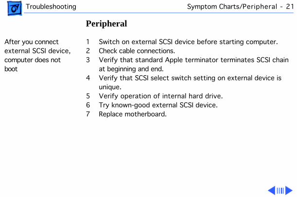
After you connect external SCSI device, computer does not boot
1 Switch on external SCSI device before starting computer.2 Check cable connections.3 Verify that standard Apple terminator terminates SCSI chain
at beginning and end.4 Verify that SCSI select switch setting on external device is
unique.5 Verify operation of internal hard drive.6 Try known-good external SCSI device.7 Replace motherboard.
Troubleshooting Symptom Charts/Peripheral - 22
Peripheral
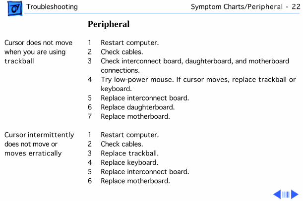
Cursor does not move when you are using trackball
1 Restart computer.2 Check cables.3 Check interconnect board, daughterboard, and motherboard
connections.4 Try low-power mouse. If cursor moves, replace trackball or
keyboard.5 Replace interconnect board.6 Replace daughterboard.7 Replace motherboard.
Cursor intermittently does not move or moves erratically
1 Restart computer.2 Check cables.3 Replace trackball.4 Replace keyboard.5 Replace interconnect board.6 Replace motherboard.
Troubleshooting Symptom Charts/Peripheral - 23
Peripheral
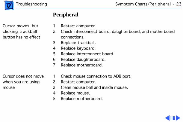
Cursor moves, but clicking trackball button has no effect
1 Restart computer.2 Check interconnect board, daughterboard, and motherboard
connections.3 Replace trackball.4 Replace keyboard.5 Replace interconnect board.6 Replace daughterboard.7 Replace motherboard.
Cursor does not move when you are using mouse
1 Check mouse connection to ADB port.2 Restart computer.3 Clean mouse ball and inside mouse.4 Replace mouse.5 Replace motherboard.
Troubleshooting Symptom Charts/Peripheral - 24
Peripheral
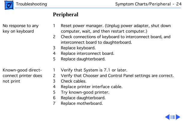
No response to any key on keyboard
1 Reset power manager. (Unplug power adapter, shut down computer, wait, and then restart computer.)
2 Check connections of keyboard to interconnect board, and interconnect board to daughterboard.
3 Replace keyboard.4 Replace interconnect board.5 Replace daughterboard.
Known-good direct-connect printer does not print
1 Verify that System is 7.1 or later.2 Verify that Chooser and Control Panel settings are correct.3 Check cables.4 Replace printer interface cable.5 Try known-good printer.6 Replace daughterboard.7 Replace motherboard.
Troubleshooting Symptom Charts/Peripheral - 25
Peripheral
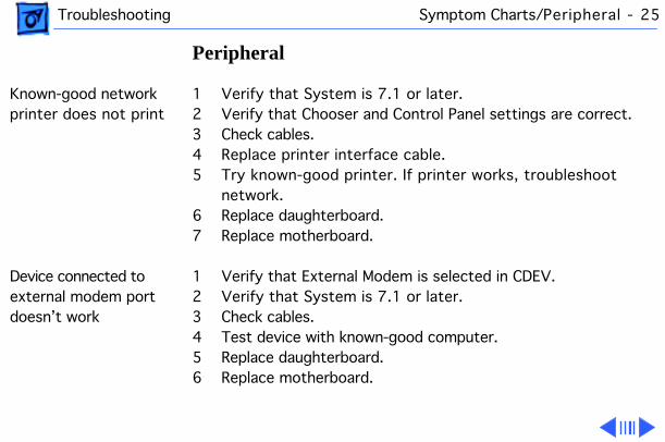
Known-good network printer does not print
1 Verify that System is 7.1 or later.2 Verify that Chooser and Control Panel settings are correct.3 Check cables.4 Replace printer interface cable.5 Try known-good printer. If printer works, troubleshoot
network.6 Replace daughterboard.7 Replace motherboard.
Device connected to external modem port doesn’t work
1 Verify that External Modem is selected in CDEV.2 Verify that System is 7.1 or later.3 Check cables.4 Test device with known-good computer.5 Replace daughterboard.6 Replace motherboard.

Troubleshooting Symptom Charts/Peripheral - 26
Peripheral
I/O devices are unrecognized or garbage is transmitted or received
1 Verify that System is 7.1 or later.2 Check cables.3 Verify that SCSI device has standard Apple terminator.4 Verify that SCSI select switch setting on external device is
unique.5 Test device with known-good computer.6 Replace daughterboard.7 Replace motherboard.
Troubleshooting Symptom Charts/Internal Modem - 27
Internal Modem
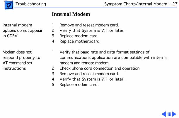
Internal modem options do not appear in CDEV
1 Remove and reseat modem card.2 Verify that System is 7.1 or later.3 Replace modem card.4 Replace motherboard.
Modem does not respond properly to AT command set instructions
1 Verify that baud rate and data format settings of communications application are compatible with internal modem and remote modem.
2 Check phone cord connection and operation.3 Remove and reseat modem card.4 Verify that System is 7.1 or later.5 Replace modem card.
Troubleshooting Symptom Charts/Internal Modem - 28
Internal Modem
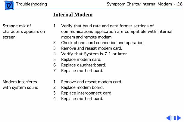
Strange mix of characters appears on screen
1 Verify that baud rate and data format settings of communications application are compatible with internal modem and remote modem.
2 Check phone cord connection and operation.3 Remove and reseat modem card.4 Verify that System is 7.1 or later.5 Replace modem card.6 Replace daughterboard.7 Replace motherboard.
Modem interferes with system sound
1 Remove and reseat modem card.2 Replace modem board.3 Replace interconnect card.4 Replace motherboard.
Troubleshooting Symptom Charts/Internal Modem - 29
Internal Modem
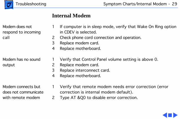
Modem does not respond to incoming call
1 If computer is in sleep mode, verify that Wake On Ring option in CDEV is selected.
2 Check phone cord connection and operation.3 Replace modem card.4 Replace motherboard.
Modem has no sound output
1 Verify that Control Panel volume setting is above 0.2 Replace modem card.3 Replace interconnect card.4 Replace motherboard.
Modem connects but does not communicate with remote modem
1 Verify that remote modem needs error correction (error correction is internal modem default).
2 Type AT &Q0 to disable error correction.

Troubleshooting Symptom Charts/Miscellaneous - 30
Miscellaneous
Screen goes blank and computer shuts down every few minutes
Adjust sleep delays in Control Panel or connect power adapter.
Application seems to run slower after few seconds
1 Disable System Rest. (See owner’s manual.)2 Connect power adapter.
Hard drive is slow to respond, or screen goes blank too often
Adjust sleep delays in Control Panel or connect power adapter.

Troubleshooting Symptom Charts/Miscellaneous - 31
Miscellaneous
No sound from speaker
1 Verify that volume setting in Control Panel is above 0.2 Verify that no external speaker is plugged in.3 Check connections of speaker to interconnect board,
interconnect board to daughterboard, and daughterboard to motherboard.
4 Replace interconnect board.5 Replace daughterboard.6 Replace motherboard.

Troubleshooting PowerBook 165c/180c Startup Problems Flowchart/
PowerBook 165c/180c Startup Problems Flowchart
START
Reset the powermanager.
Press the power button tobegin the startup sequence.
Do thestartup tones
sound?
No
Yes
Is the startup tone
normal?
Yes
Does any video
appear?
No
Yes
See Startup Problems inthe Symptom/Cure Chart.
No
1. Check the cables.2. Replace the inverter board.3. Replace the interconnect board.4. Replace the display cable. PowerBook 520, 520c, 540, 540c: Replace the interconnect- to-display cable.5. Replace the display. PowerBook 170, 180, 180c: Replace the display (international only) or return the computer to Apple.6. Replace the daughterboard.7. Replace the motherboard.
1. Check the cables.2. Replace the interconnect board.3. Replace the daughterboard.4. Replace the motherboard.
Does agray pattern
appear?
Yes
No
1
1. Replace the daughterboard.2. Replace the motherboard.
Troubleshooting PowerBook 165c/180c Startup Problems Flowchart/
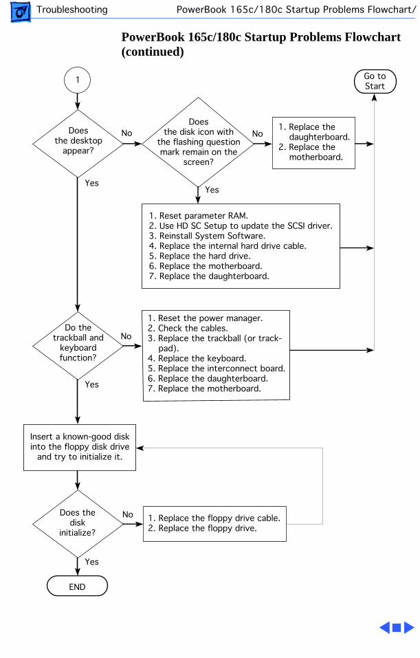
PowerBook 165c/180c Startup Problems Flowchart (continued)
1. Replace the daughterboard.2. Replace the motherboard.
END
Doesthe desktop
appear?
No
Yes
No
Yes
NoDo the
trackball andkeyboardfunction?
1. Reset the power manager.2. Check the cables.3. Replace the trackball (or track- pad).4. Replace the keyboard.5. Replace the interconnect board.6. Replace the daughterboard.7. Replace the motherboard.Yes
Doesthe disk icon with
the flashing questionmark remain on the
screen?
1 Go toStart
Insert a known-good diskinto the floppy disk drive
and try to initialize it.
NoDoes thedisk
initialize?
Yes
1. Reset parameter RAM.2. Use HD SC Setup to update the SCSI driver.3. Reinstall System Software.4. Replace the internal hard drive cable.5. Replace the hard drive.6. Replace the motherboard.7. Replace the daughterboard.
1. Replace the floppy drive cable.2. Replace the floppy drive.

Service Source
K
Take Apart
PowerBook 165c/180c
Take Apart Main Battery - 1
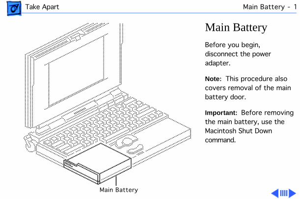
Main Battery
Before you begin, disconnect the power adapter.
Note:
This procedure also covers removal of the main battery door.
Important:
Before removing the main battery, use the Macintosh Shut Down command.
Main Battery

Take Apart Main Battery - 2
±
Warning:
The main battery contains toxic materials. Review battery handling and disposal instructions in Bulletins/Safety.
1 Slide open the battery door.
2 Using the battery door as a handle, pull out the main battery.
Take Apart Main Battery - 3
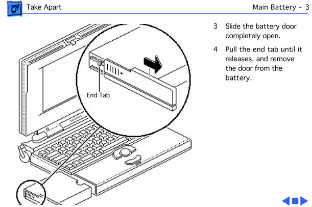
3 Slide the battery door completely open.
4 Pull the end tab until it releases, and remove the door from the battery.
End Tab

Take Apart I/O Door - 4
I/O Door
No preliminary steps are required before you begin this procedure.
Caution:
The PowerBook 165c/180c contains CMOS devices that are very susceptible to ESD damage. Review the ESD precautions in Bulletins/Safety.
I/O Door
Take Apart I/O Door - 5
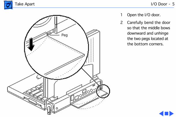
1 Open the I/O door.
2 Carefully bend the door so that the middle bows downward and unhinge the two pegs located at the bottom corners.
Peg
Take Apart Top Case - 6
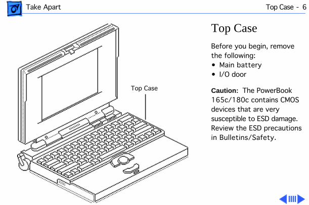
Top Case
Before you begin, remove the following:• Main battery• I/O door
Caution:
The PowerBook 165c/180c contains CMOS devices that are very susceptible to ESD damage. Review the ESD precautions in Bulletins/Safety.
Top Case

Take Apart Top Case - 7
1
Note:
Use a T-8 Torx driver to remove the small screw from the rear connector panel and a T-10 Torx driver to remove the other case screws.
Remove the five Torx screws from the bottom case.
Take Apart Top Case - 8
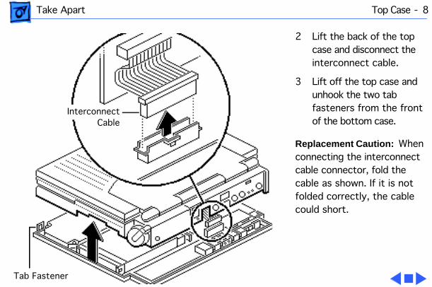
2 Lift the back of the top case and disconnect the interconnect cable.
3 Lift off the top case and unhook the two tab fasteners from the front of the bottom case.
Replacement Caution:
When connecting the interconnect cable connector, fold the cable as shown. If it is not folded correctly, the cable could short.
InterconnectCable
Tab Fastener

Take Apart Trackball Assembly - 9
Trackball Assembly
Before you begin, remove the following:• Main battery• I/O door• Top case
Caution:
The PowerBook 165c/180c contains CMOS devices that are very susceptible to ESD damage. Review the ESD precautions in Bulletins/Safety.
TrackballAssembly
Take Apart Trackball Assembly - 10
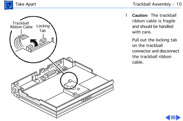
1
Caution:
The trackball ribbon cable is fragile and should be handled with care.
Pull out the locking tab on the trackball connector and disconnect the trackball ribbon cable.
Trackball Ribbon Cable Locking
Tab
Take Apart Trackball Assembly - 11
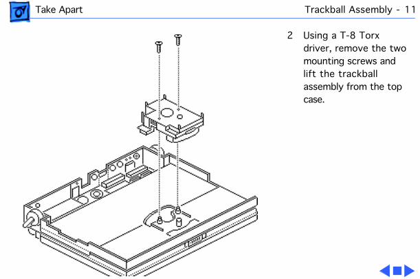
2 Using a T-8 Torx driver, remove the two mounting screws and lift the trackball assembly from the top case.
Take Apart Keyboard - 12
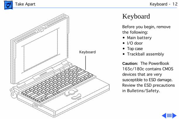
Keyboard
Before you begin, remove the following:• Main battery• I/O door• Top case• Trackball assembly
Caution:
The PowerBook 165c/180c contains CMOS devices that are very susceptible to ESD damage. Review the ESD precautions in Bulletins/Safety.
Keyboard
Take Apart Keyboard - 13
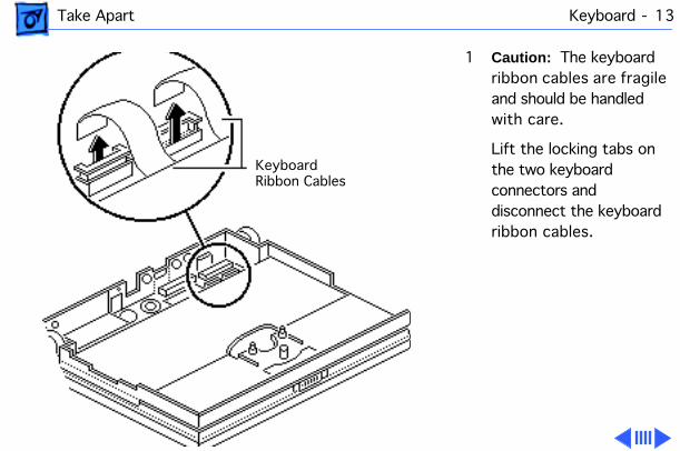
1
Caution:
The keyboard ribbon cables are fragile and should be handled with care.
Lift the locking tabs on the two keyboard connectors and disconnect the keyboard ribbon cables.
KeyboardRibbon Cables
Take Apart Keyboard - 14
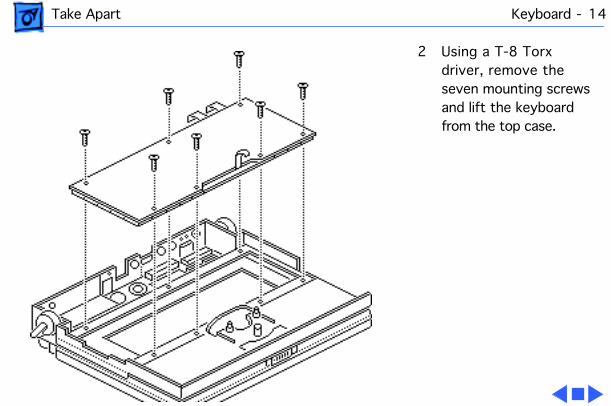
2 Using a T-8 Torx driver, remove the seven mounting screws and lift the keyboard from the top case.
Take Apart DC/DC Converter - 15
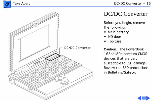
DC/DC Converter
Before you begin, remove the following:• Main battery• I/O door• Top case
Caution:
The PowerBook 165c/180c contains CMOS devices that are very susceptible to ESD damage. Review the ESD precautions in Bulletins/Safety.
DC/DC Converter
Take Apart DC/DC Converter - 16
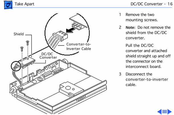
1 Remove the two mounting screws.
2
Note:
Do not remove the shield from the DC/DC converter.
Pull the DC/DC converter and attached shield straight up and off the connector on the interconnect board.
3 Disconnect the converter-to-inverter cable.
Converter-to-Inverter Cable
DC/DCConverter
Shield
Take Apart DC/DC Converter - 17
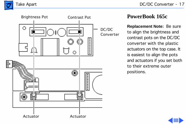
PowerBook 165c
Replacement Note:
Be sure to align the brightness and contrast pots on the DC/DC converter with the plastic actuators on the top case. It is easiest to align the pots and actuators if you set both to their extreme outer positions.
Brightness Pot Contrast Pot
DC/DCConverter
Actuator Actuator
Take Apart DC/DC Converter - 18
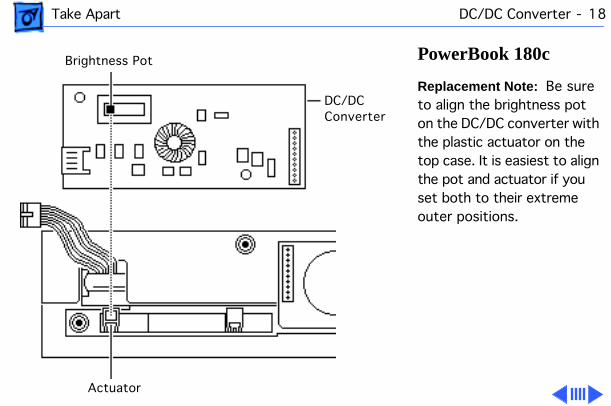
PowerBook 180c
Replacement Note:
Be sure to align the brightness pot on the DC/DC converter with the plastic actuator on the top case. It is easiest to align the pot and actuator if you set both to their extreme outer positions.
Brightness Pot
DC/DCConverter
Actuator
Take Apart DC/DC Converter - 19
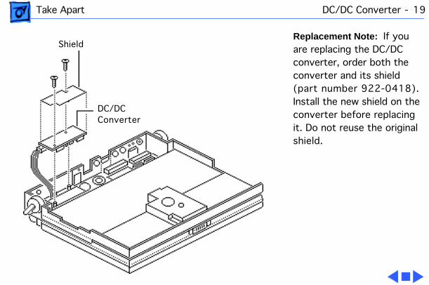
Replacement Note:
If you are replacing the DC/DC converter, order both the converter and its shield (part number 922-0418). Install the new shield on the converter before replacing it. Do not reuse the original shield.
Shield
DC/DCConverter
Take Apart Interconnect Board - 20
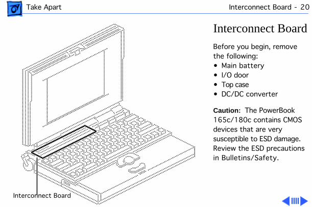
Interconnect Board
Before you begin, remove the following:• Main battery• I/O door• Top case• DC/DC converter
Caution:
The PowerBook 165c/180c contains CMOS devices that are very susceptible to ESD damage. Review the ESD precautions in Bulletins/Safety.
Interconnect Board

Take Apart Interconnect Board - 21
±
Warning:
The interconnect board contains hazardous materials. Return bad interconnect boards to Apple for proper disposal.
1
Caution:
The keyboard and display cables are fragile and should be handled with care.
Lift the locking tabs on connectors J5 and J3 and disconnect the keyboard ribbon cables.
J5 Connector
J3 Connector
Take Apart Interconnect Board - 22
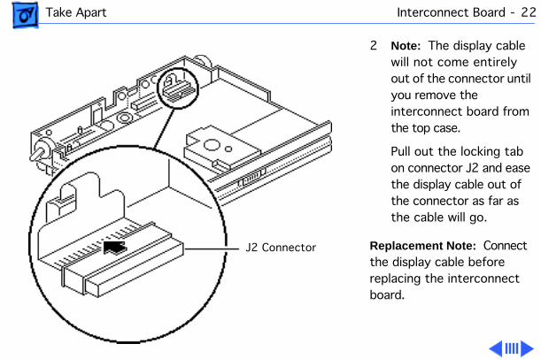
2
Note:
The display cable will not come entirely out of the connector until you remove the interconnect board from the top case.
Pull out the locking tab on connector J2 and ease the display cable out of the connector as far as the cable will go.
Replacement Note:
Connect the display cable before replacing the interconnect board.
J2 Connector
Take Apart Interconnect Board - 23
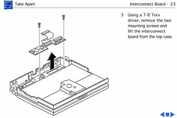
3 Using a T-8 Torx driver, remove the two mounting screws and lift the interconnect board from the top case.
Take Apart Actuators - 24
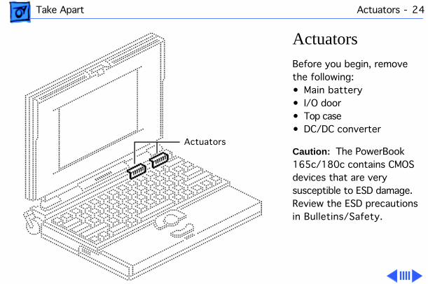
Actuators
Before you begin, remove the following:• Main battery• I/O door• Top case• DC/DC converter
Caution:
The PowerBook 165c/180c contains CMOS devices that are very susceptible to ESD damage. Review the ESD precautions in Bulletins/Safety.
Actuators

Take Apart Actuators - 25
Replacement Note:
The PowerBook 180c has only one brightness actuator.
1 Pull up the contrast actuator, rotate it toward the display, and remove the actuator from the top case.
2 Repeat for the brightness actuator.
Take Apart Elevation Foot - 26
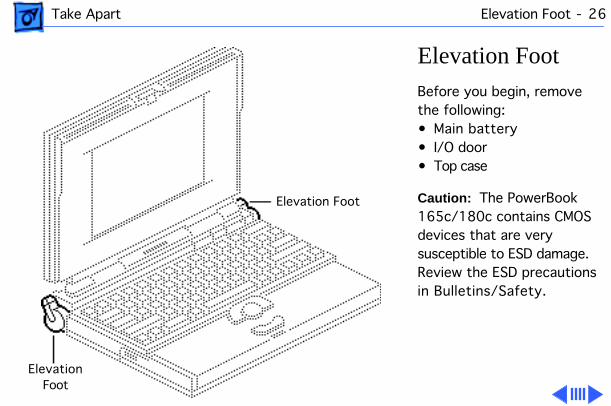
Elevation Foot
Before you begin, remove the following:• Main battery• I/O door• Top case
Caution:
The PowerBook 165c/180c contains CMOS devices that are very susceptible to ESD damage. Review the ESD precautions in Bulletins/Safety.
Elevation Foot
ElevationFoot

Take Apart Elevation Foot - 27
1 Using a T-8 Torx driver, remove the Torx screw, washer, and spring clip from the inside of the elevation foot.
2 Pull off the elevation foot.
ElevationFoot
SpringClip
Take Apart Cousin Card - 28
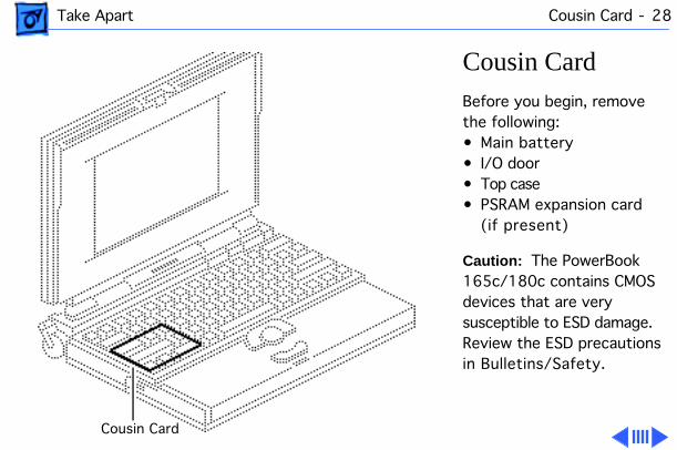
Cousin Card
Before you begin, remove the following:• Main battery• I/O door• Top case• PSRAM expansion card
(if present)
Caution:
The PowerBook 165c/180c contains CMOS devices that are very susceptible to ESD damage. Review the ESD precautions in Bulletins/Safety.
Cousin Card

Take Apart Cousin Card - 29
Caution:
Always use the logic board take-apart tool to separate the cousin card connector from the daughterboard connector. Trying to disconnect the cousin card from the daughterboard by rocking or peeling the boards apart damages the connectors.
Using the Apple logic board take-apart tool, disconnect the cousin card from the daughterboard.
Cousin Card
Daughterboard
Logic BoardTake-Apart
Tool
Take Apart Daughterboard - 30
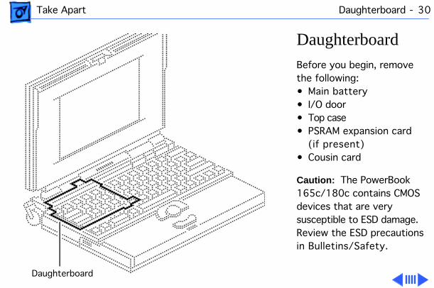
Daughterboard
Before you begin, remove the following:• Main battery• I/O door• Top case• PSRAM expansion card
(if present)• Cousin card
Caution:
The PowerBook 165c/180c contains CMOS devices that are very susceptible to ESD damage. Review the ESD precautions in Bulletins/Safety.
Daughterboard

Take Apart Daughterboard - 31
1 Using a T-8 Torx driver, remove the four daughterboard mounting screws.
2
Caution:
Always use the logic board take-apart tool to separate the daughterboard connector from the motherboard connector. Trying to disconnect the daughterboard from the motherboard by rocking or peeling the boards apart damages the connectors.
Daughterboard
Motherboard
Logic BoardTake-Apart
Tool
Take Apart Daughterboard - 32
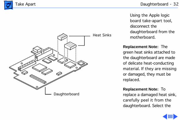
Using the Apple logic board take-apart tool, disconnect the daughterboard from the motherboard.
Replacement Note:
The green heat sinks attached to the daughterboard are made of delicate heat-conducting material. If they are missing or damaged, they must be replaced.
Replacement Note:
To replace a damaged heat sink, carefully peel it from the daughterboard. Select the
Heat Sinks
Daughterboard
Take Apart Daughterboard - 33
appropriately sized heat sink from the heat sink kit (part number 076-0069), and gently press the part into place.
Replacement Caution:
Make sure the heat sink is placed exactly as shown in the illustration. The heat sink should not hang over the side of the component it is covering, or it may short the component leads.
Take Apart Motherboard - 34
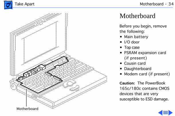
Motherboard
Before you begin, remove the following:• Main battery• I/O door• Top case• PSRAM expansion card
(if present)• Cousin card• Daughterboard• Modem card (if present)
Caution:
The PowerBook 165c/180c contains CMOS devices that are very susceptible to ESD damage.
Motherboard
Take Apart Motherboard - 35
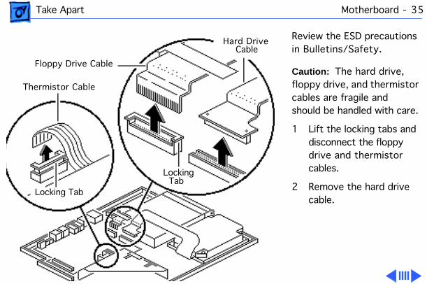
Review the ESD precautions in Bulletins/Safety.
Caution:
The hard drive, floppy drive, and thermistor cables are fragile and should be handled with care.
1 Lift the locking tabs and disconnect the floppy drive and thermistor cables.
2 Remove the hard drive cable.
Hard DriveCable
Floppy Drive Cable
Thermistor Cable
Locking Tab
Locking Tab

Take Apart Motherboard - 36
3 Remove the two hex-head screws and lift the motherboard from the bottom case.
Hex-Head Screw
Motherboard

Take Apart Motherboard - 37
Replacement Note: To replace the insulator on the sound jack assembly, carefully peel off the original insulator. Remove the paper backing on the replacement insulator, and gently press it into place.
Replacement Caution: Make sure the replacement insulator sits in exactly the same position as the original insulator.
Sound Jack Insulator
Sound JackAssembly
Motherboard
Take Apart Hard Drive - 38
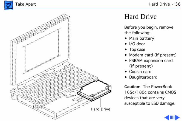
Hard DriveBefore you begin, remove the following:• Main battery• I/O door• Top case• Modem card (if present)• PSRAM expansion card
(if present)• Cousin card• Daughterboard
Caution: The PowerBook 165c/180c contains CMOS devices that are very susceptible to ESD damage.
Hard Drive
Take Apart Hard Drive - 39
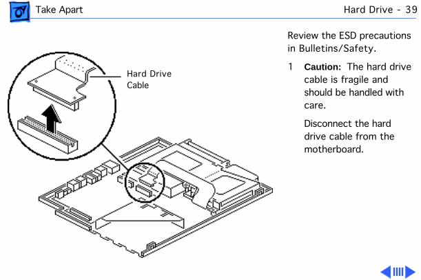
Review the ESD precautions in Bulletins/Safety.
1 Caution: The hard drive cable is fragile and should be handled with care.
Disconnect the hard drive cable from the motherboard.
Hard DriveCable
Take Apart Hard Drive - 40
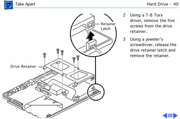
2 Using a T-8 Torx driver, remove the five screws from the drive retainer.
3 Using a jeweler’s screwdriver, release the drive retainer latch and remove the retainer.
RetainerLatch
Drive Retainer
Take Apart Hard Drive - 41
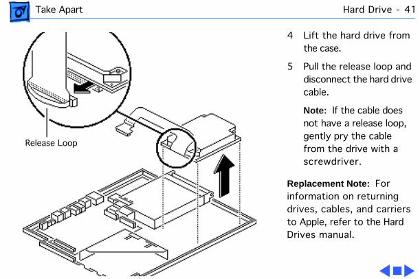
4 Lift the hard drive from the case.
5 Pull the release loop and disconnect the hard drive cable.
Note: If the cable does not have a release loop, gently pry the cable from the drive with a screwdriver.
Replacement Note: For information on returning drives, cables, and carriers to Apple, refer to the Hard Drives manual.
Release Loop
Take Apart Floppy Drive - 42
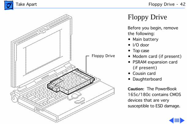
Floppy DriveBefore you begin, remove the following:• Main battery• I/O door• Top case• Modem card (if present)• PSRAM expansion card
(if present)• Cousin card• Daughterboard
Caution: The PowerBook 165c/180c contains CMOS devices that are very susceptible to ESD damage.
Floppy Drive
Take Apart Floppy Drive - 43
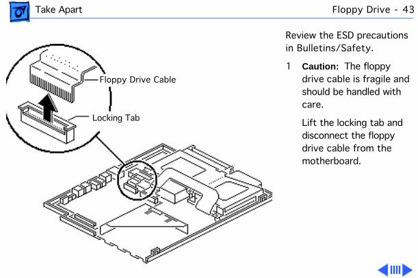
Review the ESD precautions in Bulletins/Safety.
1 Caution: The floppy drive cable is fragile and should be handled with care.
Lift the locking tab and disconnect the floppy drive cable from the motherboard.
Floppy Drive Cable
Locking Tab

Take Apart Floppy Drive - 44
2 Using a T-8 Torx driver, remove the five Torx screws from the drive retainer.
3 Using a jeweler’s screwdriver, release the drive retainer latch and remove the retainer.
RetainerLatch
Drive Retainer
Take Apart Floppy Drive - 45
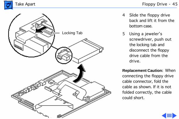
4 Slide the floppy drive back and lift it from the bottom case.
5 Using a jeweler’s screwdriver, push out the locking tab and disconnect the floppy drive cable from the drive.
Replacement Caution: When connecting the floppy drive cable connector, fold the cable as shown. If it is not folded correctly, the cable could short.
Locking Tab
Take Apart Floppy Drive - 46
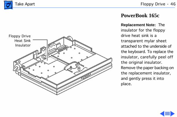
PowerBook 165c
Replacement Note: The insulator for the floppy drive heat sink is a transparent mylar sheet attached to the underside of the keyboard. To replace the insulator, carefully peel off the original insulator. Remove the paper backing on the replacement insulator, and gently press it into place.
Floppy DriveHeat SinkInsulator
Take Apart Floppy Drive - 47
Replacement Caution: Make sure the replacement insulator sits in exactly the same position as the original insulator.
Take Apart Display Bezel - 48
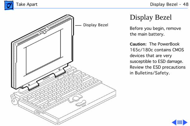
Display BezelBefore you begin, remove the main battery.
Caution: The PowerBook 165c/180c contains CMOS devices that are very susceptible to ESD damage. Review the ESD precautions in Bulletins/Safety.
Display Bezel
Take Apart Display Bezel - 49
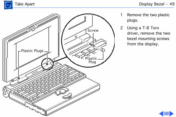
1 Remove the two plastic plugs.
2 Using a T-8 Torx driver, remove the two bezel mounting screws from the display.
Screw
PlasticPlug
Plastic Plugs
Take Apart Display Bezel - 50
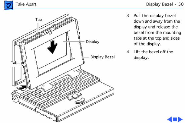
3 Pull the display bezel down and away from the display and release the bezel from the mounting tabs at the top and sides of the display.
4 Lift the bezel off the display.
Display
Display Bezel
Tab
Tab
Take Apart DC/AC Inverter - 51
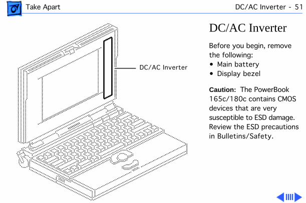
DC/AC InverterBefore you begin, remove the following:• Main battery• Display bezel
Caution: The PowerBook 165c/180c contains CMOS devices that are very susceptible to ESD damage. Review the ESD precautions in Bulletins/Safety.
DC/AC Inverter

Take Apart DC/AC Inverter - 52
1 Disconnect the inverter-to-display cable from the DC/AC inverter.
2 Using a Phillips #0 screwdriver, remove the two screws.
3 Lift the DC/AC inverter off the display housing.
4 Disconnect the converter-to-inverter cable.
Inverter-to-Display Cable
Converter-to-InverterCable

Take Apart DC/AC Inverter - 53
Replacement Note: To avoid pinching the converter-to-inverter cable, route the cable around the bottom right corner of the display.
Take Apart Clutches/Display Housing - 54
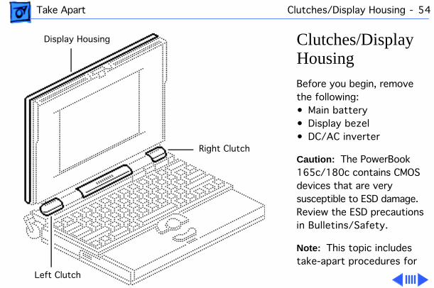
Clutches/Display HousingBefore you begin, remove the following:• Main battery• Display bezel• DC/AC inverter
Caution: The PowerBook 165c/180c contains CMOS devices that are very susceptible to ESD damage. Review the ESD precautions in Bulletins/Safety.
Note: This topic includes take-apart procedures for
Right Clutch
Left Clutch
Display Housing

Take Apart Clutches/Display Housing - 55
the left and right clutch assemblies and the display housing.
1 Cover the keyboard with a clean cloth or sheet of paper.
2 Using a T-8 Torx driver, remove the four display mounting screws.
Display Housing
EMI Shield
Display
Take Apart Clutches/Display Housing - 56
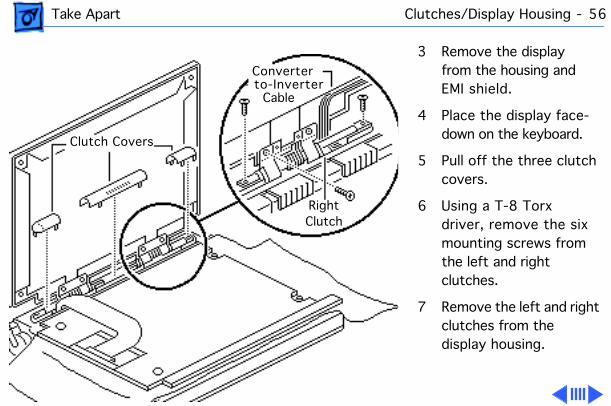
3 Remove the display from the housing and EMI shield.
4 Place the display face-down on the keyboard.
5 Pull off the three clutch covers.
6 Using a T-8 Torx driver, remove the six mounting screws from the left and right clutches.
7 Remove the left and right clutches from the display housing.
Converter
Cable- to-Inverter
RightClutch
Clutch Covers
Take Apart Clutches/Display Housing - 57
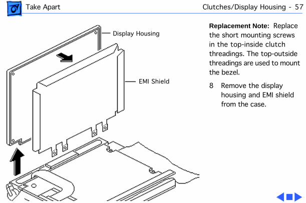
Replacement Note: Replace the short mounting screws in the top-inside clutch threadings. The top-outside threadings are used to mount the bezel.
8 Remove the display housing and EMI shield from the case.
EMI Shield
Display Housing
Take Apart Converter-to-Inverter Cable - 58
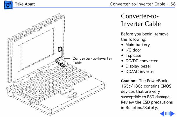
Converter-to-Inverter CableBefore you begin, remove the following:• Main battery• I/O door• Top case• DC/DC converter• Display bezel• DC/AC inverter
Caution: The PowerBook 165c/180c contains CMOS devices that are very susceptible to ESD damage. Review the ESD precautions in Bulletins/Safety.
Converter-to-InverterCable
Take Apart Converter-to-Inverter Cable - 59
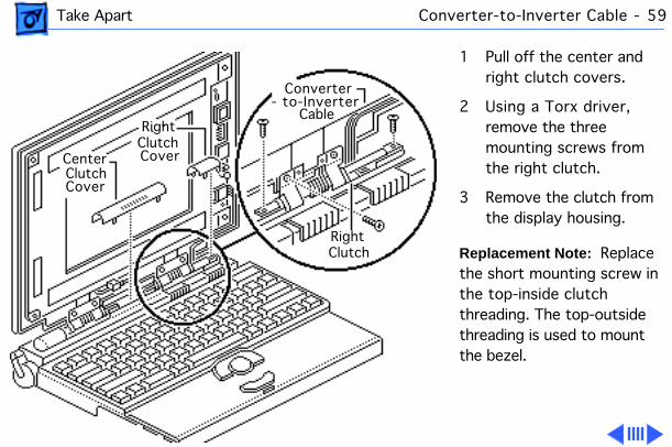
1 Pull off the center and right clutch covers.
2 Using a Torx driver, remove the three mounting screws from the right clutch.
3 Remove the clutch from the display housing.
Replacement Note: Replace the short mounting screw in the top-inside clutch threading. The top-outside threading is used to mount the bezel.
Converter
Cable- to-Inverter
RightClutch
RightClutchCoverCenter
ClutchCover

Take Apart Converter-to-Inverter Cable - 60
4 Remove the converter-to-inverter cable from the case.
Replacement Note: To avoid pinching the converter-to-inverter cable, route the cable around the bottom right corner of the display.
Converter-to-Inverter Cable
Take Apart Display - 61
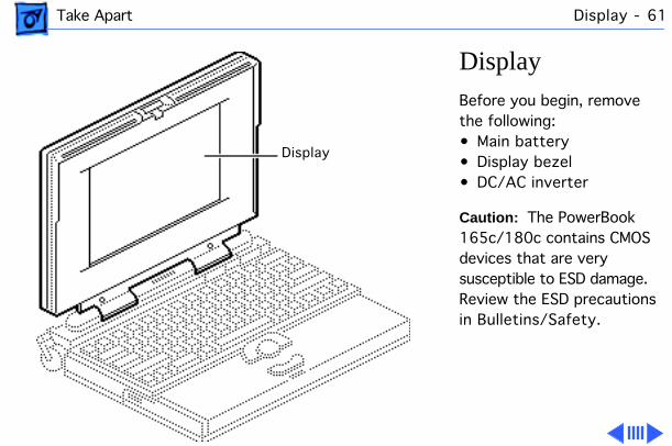
DisplayBefore you begin, remove the following:• Main battery• Display bezel• DC/AC inverter
Caution: The PowerBook 165c/180c contains CMOS devices that are very susceptible to ESD damage. Review the ESD precautions in Bulletins/Safety.
Display

Take Apart Display - 62
PowerBook 180c Display (CPRC/Intl. Only)
Note: The PowerBook 180c active-matrix display module is available to CPRC and international repairers only.
Caution: The display cable is fragile and should be handled with care.
1 Cover the keyboard with a clean cloth or sheet of paper.
Display
EMI Shield
Display Housing
Take Apart Display - 63
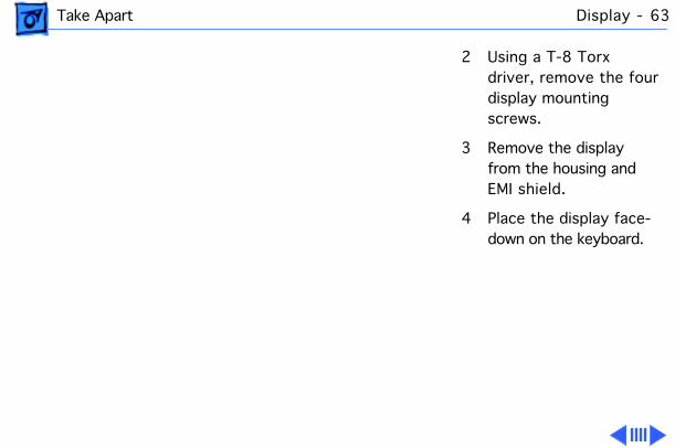
2 Using a T-8 Torx driver, remove the four display mounting screws.
3 Remove the display from the housing and EMI shield.
4 Place the display face-down on the keyboard.

Take Apart Display - 64
PowerBook 180c (All Service Providers)1 Using an IC extractor,
disconnect the display cable from the two connectors.
2 Caution: The display cable is attached to the display with adhesive near the base of the display. Carefully pry up the cable at this point.
Gently detach the display cable from the
Take Apart Display - 65
back of the display.
3 Remove the display.
Replacement Note: Before returning the defective display to Apple, be sure to transfer the protective plastic from the replacement display to the defective display.
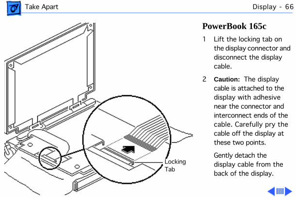
Take Apart Display - 66
PowerBook 165c 1 Lift the locking tab on
the display connector and disconnect the display cable.
2 Caution: The display cable is attached to the display with adhesive near the connector and interconnect ends of the cable. Carefully pry the cable off the display at these two points.
Gently detach the display cable from the back of the display.
LockingTab
Take Apart Display - 67
3 Remove the display.
Replacement Note: Before returning the defective display to Apple, be sure to transfer the protective plastic from the replacement display to the defective display.
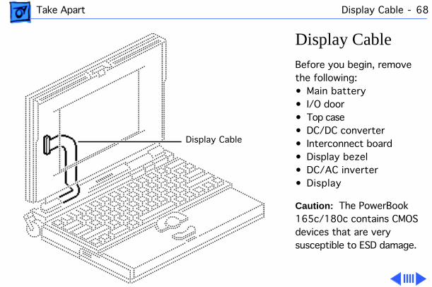
Take Apart Display Cable - 68
Display CableBefore you begin, remove the following:• Main battery• I/O door• Top case• DC/DC converter• Interconnect board• Display bezel• DC/AC inverter• Display
Caution: The PowerBook 165c/180c contains CMOS devices that are very susceptible to ESD damage.
Display Cable

Take Apart Display Cable - 69
Review the ESD precautions in Bulletins/Safety.
Note: The PowerBook 180c display cable has two connectors on the end.
Caution: The display cable is fragile and should be handled with care.
1 Pry the display cable ferrite bead from the case.
Ferrite Bead

Take Apart Display Cable - 70
2 Pull off the center and left clutch covers.
3 Using a T-8 Torx driver, remove the three mounting screws from the left clutch.
4 Remove the clutch from the display housing.
Replacement Note: Replace the short mounting screw in the top-inside clutch threading. The top-outside threading is used to mount the bezel.
Left Clutch
CenterClutchCoverLeft
ClutchCover
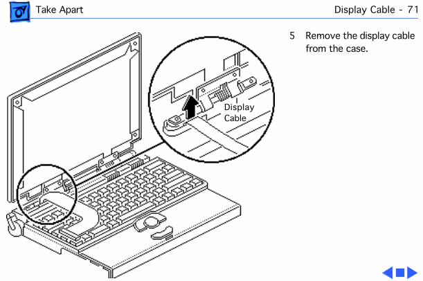
Take Apart Display Cable - 71
5 Remove the display cable from the case.
DisplayCable
Service Source
K
Upgrades
PowerBook 165c/180c

Upgrades Modem Card - 1
Modem Card
Before you begin, remove the following:• Main battery• I/O door• Top case
Caution:
The PowerBook 165c/180c contains CMOS devices that are very susceptible to ESD damage. Review the ESD precautions in Bulletins/Safety.
Modem Card

Upgrades Modem Card - 2
Caution:
If you install a third-party modem card, make sure that it does not cover any of the heat sinks on the daughterboard or over the floppy drive.
Note:
The modem card is an option for the PowerBook 165c/180c.
1 Pinch the release tabs and push out the modem port cover.
Modem Port Cover
ReleaseTabs
Upgrades Modem Card - 3
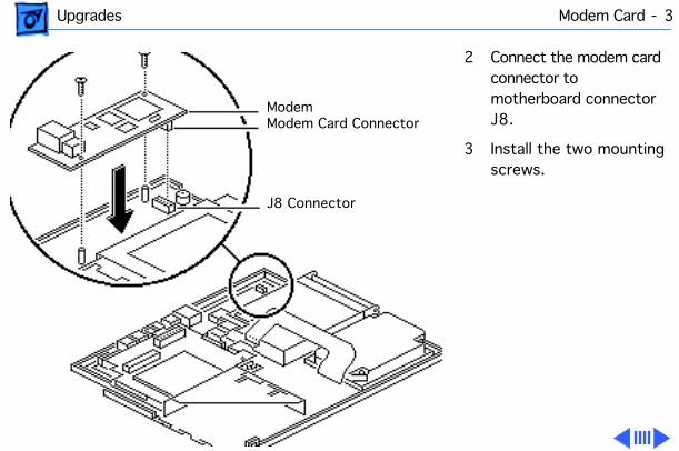
2 Connect the modem card connector to motherboard connector J8.
3 Install the two mounting screws.
ModemModem Card Connector
J8 Connector
Upgrades Modem Card - 4
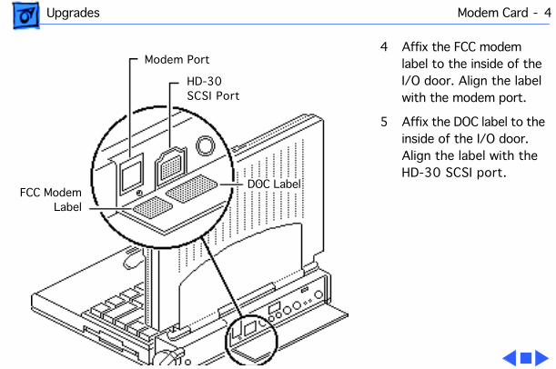
4 Affix the FCC modem label to the inside of the I/O door. Align the label with the modem port.
5 Affix the DOC label to the inside of the I/O door. Align the label with the HD-30 SCSI port.
Modem Port
HD-30SCSI Port
DOC LabelFCC Modem
Label
Upgrades PSRAM Expansion Card - 5
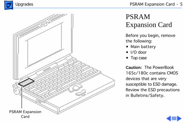
PSRAM Expansion Card
Before you begin, remove the following:• Main battery• I/O door• Top case
Caution:
The PowerBook 165c/180c contains CMOS devices that are very susceptible to ESD damage. Review the ESD precautions in Bulletins/Safety.
PSRAM ExpansionCard
Upgrades PSRAM Expansion Card - 6
Caution:
Handle the PSRAM card by the edges only. Do not touch any components on the card.
Caution:
If you install a third-party expansion card, do not remove or cover up any of the heat sinks on the daughterboard. Operating the computer without the heat sinks significantly increases the chance of daughterboard failure.
Upgrades PSRAM Expansion Card - 7
Caution:
An incorrectly installed PSRAM card could damage the daughterboard. Note that the expansion connector and the PSRAM card are keyed for proper installation. Do not force the card into the connector, thereby defeating the key.
Caution:
When installing the card, press down on the edge directly above the connector. Be careful not to apply pressure to any components or you may permanently damage the card.
Upgrades PSRAM Expansion Card - 8
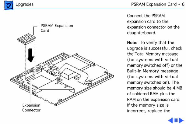
Connect the PSRAM expansion card to the expansion connector on the daughterboard.
Note:
To verify that the upgrade is successful, check the Total Memory message (for systems with virtual memory switched off) or the Built-in Memory message (for systems with virtual memory switched on). The memory size should be 4 MB of soldered RAM plus the RAM on the expansion card. If the memory size is incorrect, replace the
PSRAM ExpansionCard
ExpansionConnector
Upgrades PSRAM Expansion Card - 9
expansion card. If the memory size is still incorrect, send the computer to Apple.

Service Source
K
Additional Procedures
PowerBook 165c/180c

Additional Procedures Power Manager Reset - 1
Power Manager Reset
Reset the power manager if• The battery and power adapter are proven good, but the
computer will not power on.• The computer will not reset after a system crash.
To reset the power manager in a PowerBook 165c/180c,
1 Remove the AC adapter and the battery.
2 Let the unit sit without power hooked up for 3–5 minutes.
3 Reinstall the battery and, if necessary, reconnect the AC adapter.
4 Turn on the computer.
If this does not reset the Power Manager,
Additional Procedures Power Manager Reset - 2
5 Remove the AC adapter and the battery.
6 Let the unit sit without power hooked up for 3–5 minutes.
7 Using two paper clips, simultaneously hold down the reset and interrupt buttons for 5–10 seconds.
8 Reinstall the battery and, if necessary, reconnect the AC adapter.
9 Turn on the computer.
Additional Procedures Battery Recharger - 3
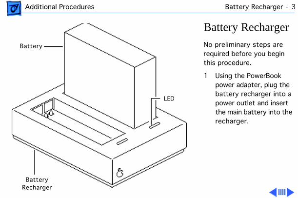
Battery Recharger
No preliminary steps are required before you begin this procedure.
1 Using the PowerBook power adapter, plug the battery recharger into a power outlet and insert the main battery into the recharger.
LED
BatteryRecharger
Battery

Additional Procedures Battery Recharger - 4
2 Track the status of the battery. If the LED is• Yellow, the battery is
charging• Green, the battery is
ready to use• Off, the charger is
unplugged, the battery is bad, the power adapter is defective, or the charger is defective.
Additional Procedures SCSI Termination - 5
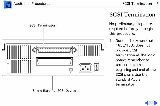
SCSI Termination
No preliminary steps are required before you begin this procedure.
1
Note:
The PowerBook 165c/180c does not provide SCSI termination at the logic board; remember to terminate at the beginning and end of the SCSI chain. Use the standard Apple terminator.
SCSI Terminator
Single External SCSI Device
Additional Procedures SCSI Termination - 6
2 When terminating SCSI devices, follow these guidelines:• Add one terminator to
a single external SCSI device, or
• Add one terminator to the first device and another to the last when there are multiple devices.
Additional Procedures Battery Handling - 7
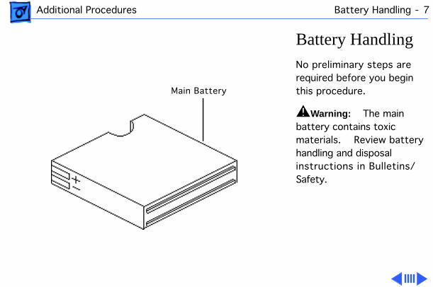
Battery Handling
No preliminary steps are required before you begin this procedure.
±
Warning:
The main battery contains toxic materials. Review battery handling and disposal instructions in Bulletins/Safety.
Main Battery
Additional Procedures Battery Handling - 8
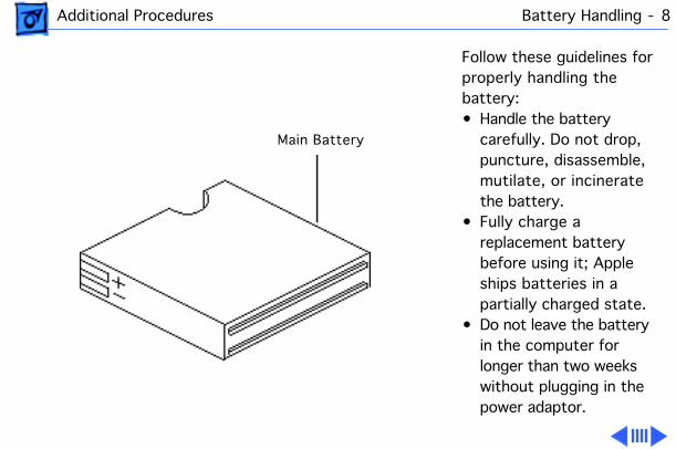
Follow these guidelines for properly handling the battery:• Handle the battery
carefully. Do not drop, puncture, disassemble, mutilate, or incinerate the battery.
• Fully charge a replacement battery before using it; Apple ships batteries in a partially charged state.
• Do not leave the battery in the computer for longer than two weeks without plugging in the power adaptor.
Main Battery

Additional Procedures Battery Handling - 9
• Completely discharge and then recharge the battery once a month.
• Store the battery in the protective battery case.
• Do not short-circuit the battery terminals.
• Keep the battery in a cool, dark place; do not store it for longer than 6 months without recharging.
Battery Case
Additional Procedures Battery Verification - 10
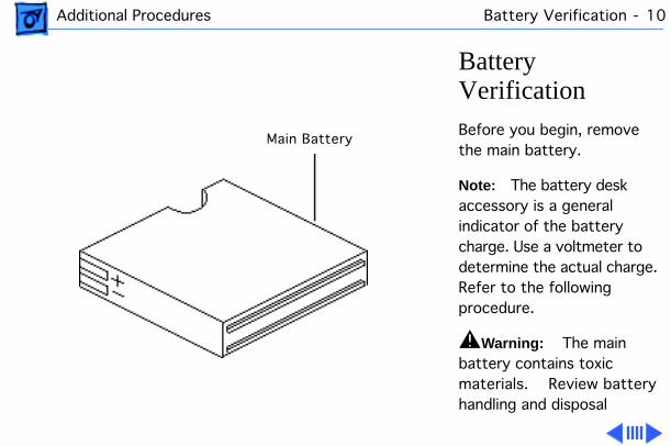
Battery Verification
Before you begin, remove the main battery.
Note:
The battery desk accessory is a general indicator of the battery charge. Use a voltmeter to determine the actual charge. Refer to the following procedure.
±
Warning:
The main battery contains toxic materials. Review battery handling and disposal
Main Battery

Additional Procedures Battery Verification - 11
instructions in Bulletins/Safety.
1 Set a voltmeter to the 10 volts DC scale.
2 Hold the positive probe of the voltmeter to the positive battery terminal and the negative probe to the negative terminal.
3 If the reading is not above 5.7 volts, recharge (first) or replace the battery.
Positive Probe
Negative Probe
Additional Procedures AC Adapter Verification - 12
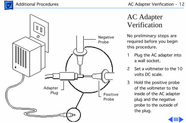
AC Adapter Verification
No preliminary steps are required before you begin this procedure.
1 Plug the AC adapter into a wall socket.
2 Set a voltmeter to the 10 volts DC scale.
3 Hold the positive probe of the voltmeter to the inside of the AC adapter plug and the negative probe to the outside of the plug.
NegativeProbe
PositiveProbe
AdapterPlug
Additional Procedures AC Adapter Verification - 13
4 If the reading is not 7.5–7.9 volts, replace the adapter.
Service Source
K
Exploded View
PowerBook 165c/180c
Exploded View 1
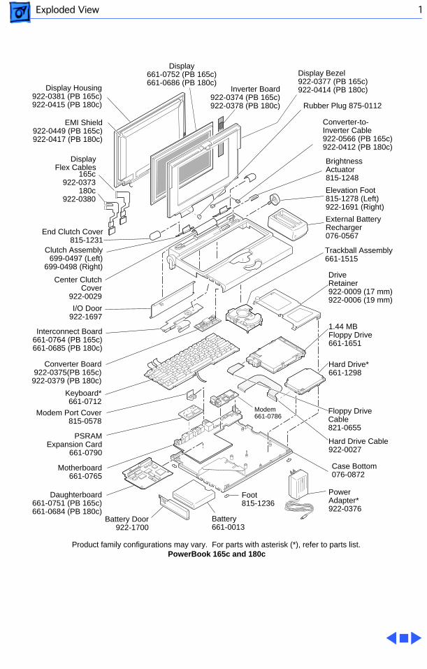
DriveRetainer922-0009 (17 mm)922-0006 (19 mm)
Modem661-0786
Interconnect Board661-0764 (PB 165c)661-0685 (PB 180c)
Product family configurations may vary. For parts with asterisk (*), refer to parts list.PowerBook 165c and 180c
Trackball Assembly661-1515
Elevation Foot815-1278 (Left)922-1691 (Right)
External BatteryRecharger076-0567
BrightnessActuator815-1248
1.44 MBFloppy Drive661-1651
Hard Drive*661-1298
Floppy DriveCable821-0655
Hard Drive Cable922-0027
PowerAdapter*922-0376
Battery661-0013
Battery Door922-1700
PSRAMExpansion Card
661-0790
Modem Port Cover815-0578
Keyboard*661-0712
Inverter Board922-0374 (PB 165c)922-0378 (PB 180c)
I/O Door922-1697
Rubber Plug 875-0112
End Clutch Cover815-1231
Center ClutchCover
922-0029
Converter-to- Inverter Cable922-0566 (PB 165c)922-0412 (PB 180c)
Converter Board
922-0375(PB 165c)922-0379 (PB 180c)
Display Bezel922-0377 (PB 165c)922-0414 (PB 180c)
Display661-0752 (PB 165c)661-0686 (PB 180c)
EMI Shield922-0449 (PB 165c)922-0417 (PB 180c)
165c922-0373
180c922-0380
Display Housing922-0381 (PB 165c)922-0415 (PB 180c)
Display Flex Cables
Clutch Assembly699-0497 (Left)
699-0498 (Right)
Daughterboard661-0751 (PB 165c)661-0684 (PB 180c)
Motherboard661-0765
Case Bottom076-0872
Foot815-1236