power u ps hip3300 presentation
TRANSCRIPT

AUSTRALIA AUSTRALIA
PowerUps UPSPowerUps UPS
HIP3300 SeriesHIP3300 Series
3Phase/3Phase series

HIP series
Module design Online UPS System
Power capacity: 10-500kVA

1. Summary
2. Appearance
3. Display
4. Principle
5. Supplement
6. Communication
7. Specification
Catalog

Mission critical & industrial applications
Operator Centres, Servers, Computer rooms, Telecom Switchgear & Infrastructures, Processing Control Equipments, Security Systems, Emergency Lighting, Fire Protection, Airport Infrastructure, Bank, Hospital, Healthcare Equipment …
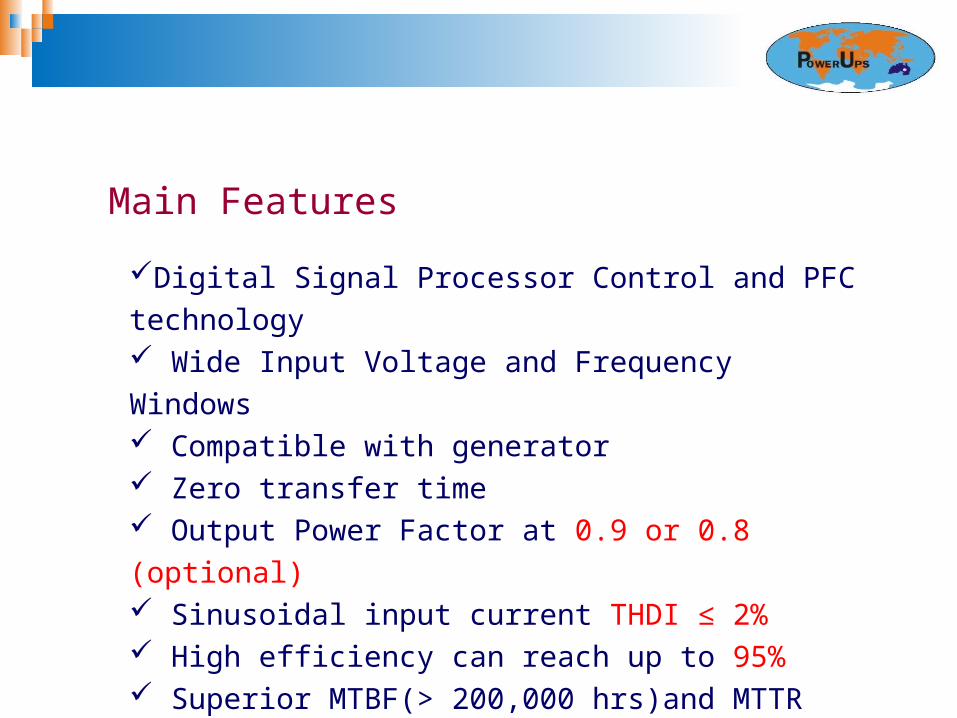
Main Features
Digital Signal Processor Control and PFC technology Wide Input Voltage and Frequency Windows Compatible with generator Zero transfer time Output Power Factor at 0.9 or 0.8 (optional) Sinusoidal input current THDI ≤ 2% High efficiency can reach up to 95% Superior MTBF(> 200,000 hrs)and MTTR ( <30 min.) ECO mode for energy saving

Main Features
Optional Battery Voltage from ± 192Vdc to ± 240Vdc Intelligent with three stages charging Modes Adjustable charging current Battery Temperature Compensation Advanced battery management Matching internal Battery also Available

Main Features
Smart Fan Speed Control Both EPO and REPO (Remote EPO) Functions Parallel Redundancy up to 4 Units Common or Separate Battery pack in parallel system Reliable protection function Easy-to-operate LCD display Megatec/Modbus Protocol Versatile Communication Interfaces
1. Summary
2. Appearance
3. Display
4. Principle
5. Supplement
6. Communication
7. Specification

10-80kVA 100-160kVA 200-300kVA 400-500kVA

10/15/20KVA
Front View(internal) Rear View (internal)
Front View(internal) Rear View (internal)

30/40K Front view (internal) 30/40k Rear view (internal)
30/40kVA

60/80KVA front view ( internal ) 60/80KVA rear view ( internal )
60/80kVA

100-160KVA
100/120KVA 160KVA

200KVA
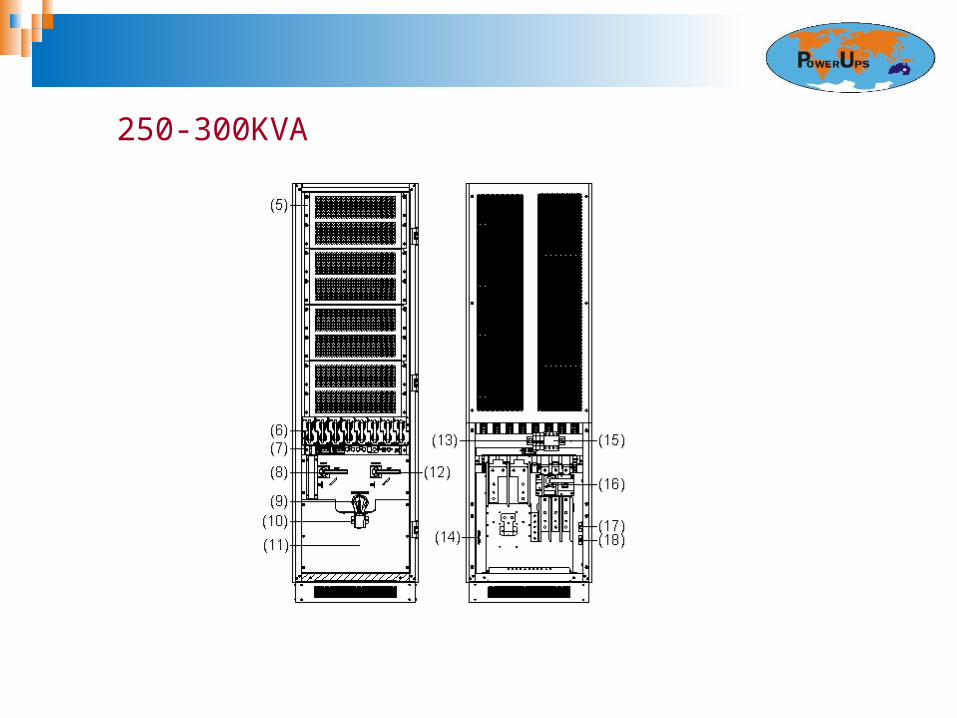
250-300KVA

400-500KVA

Power module Qty per unit
10-20K 30K 40K 60K 80K 100K
PF0.8 1 1 2 2 3 4
PF0.9 1 2 2 3 3 4
120K 160K 200K 250K 300K 400K 500K
PF0.8 4 6 5 7 8 10 13
PF0.9 5 6 5 7 8 10 13

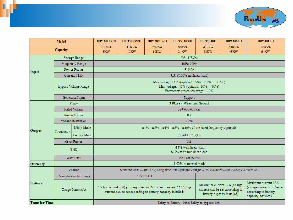
Dimension and weightModel Dimension (W*D*H) Weight (kg)10KVA (S/H) 600×780×1200 591(S)/123(H)
15KVA (S/H) 600×780×1200 594(S)/126(H)
20KVA (S/H) 600×780×1200 595(S)/127(H)
30KVA (S/H) 600×780×1200 595(S)/127(H)
40KVA 600×780×1200 158
60KVA 600×780×1200 158
80KVA 600×780×1200 195
100KVA 600×780×1600 286
120KVA 600×780×1600 286
160KVA 600×780×1600 348
200KVA 600×850×1600 380
250KVA 600×850×2000 541
300KVA 600×850×2000 575
400KVA 1200×850×2000 900
500KVA 1200×850×2000 1005

1. Applications
2. Appearance
3. Display
4. Principle
5. Supplement
6. Communication
7. Specification

LCD panelLCD panel
100-500k
10-80k

LCD Display ( 10-80K ) Operational status and mode
Input/output Voltage/Frequency
Battery Voltage/Current
Load capacity
Charge Modes/Charger Status
Internal/Ambient Temperature
Software version & model
Alarm Codes

LCD Display ( 100-500K )

Rich settings ( 10-80K) Mode setting Output voltage and frequency setting Bypass voltage upper/lower limit setting

Display
Rich settings (10-80K) Parallel ID/quantity/redundancy quantity setting
Battery capacity/quantity setting

Rich setting ( 100-500K )
1. Summary
2. Appearance
3. Display
4. Principle
5. Supplement
6. Communication
7. Specification

System block diagram
EMI PFC
LCD
BATTERY
BYPASS
BUS INVERTER EMI
AUX POWER
CHARGER
COMMUNICATION
DSP
PARALLELBOARD
I/P O/P

Power unit block diagram
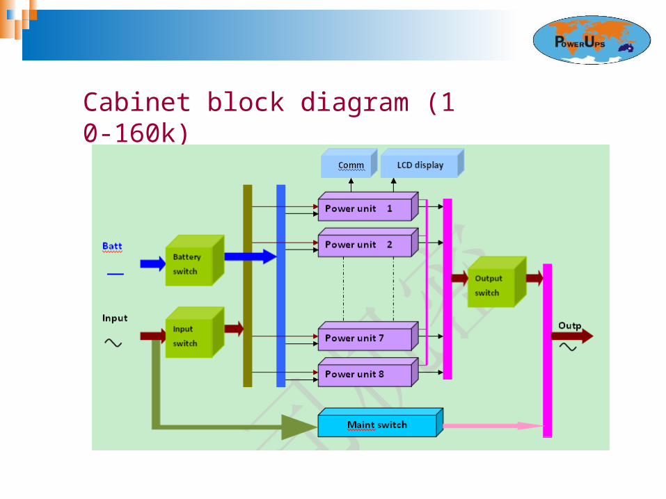
Cabinet block diagram (10-160k)
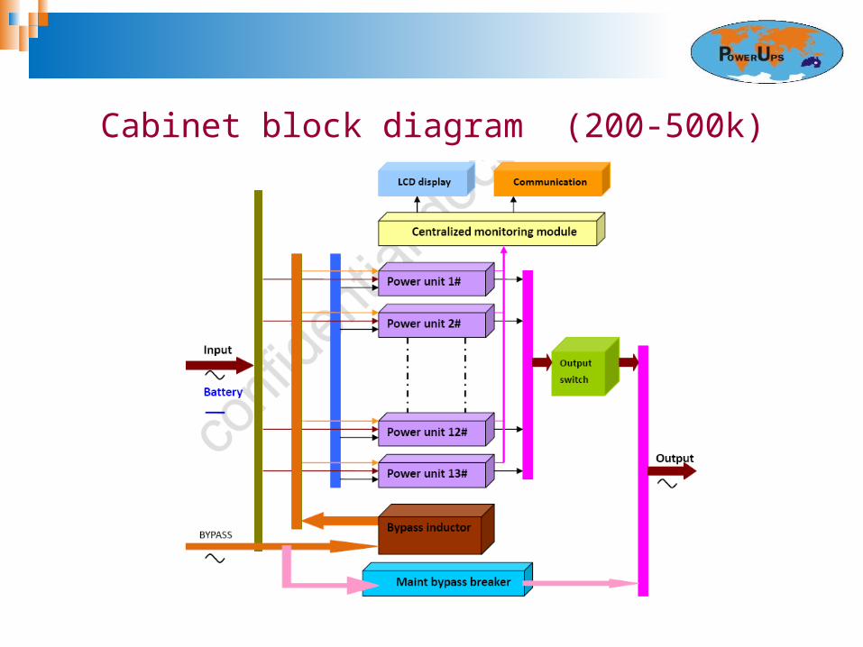
Cabinet block diagram (200-500k)

Power unit Topology
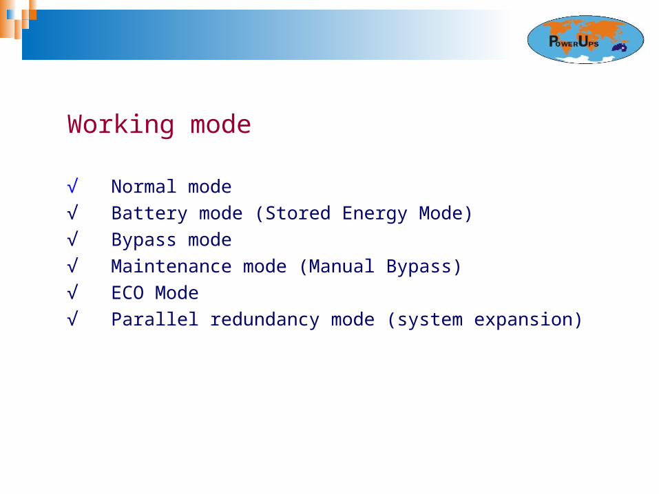
Working mode
√ Normal mode√ Battery mode (Stored Energy Mode)√ Bypass mode√ Maintenance mode (Manual Bypass)√ ECO Mode√ Parallel redundancy mode (system expansion)

1. Summary
2. Appearance
3. Display
4. Principle
5. Supplement
6. Communication
7. Specification

Supplement
Powerful Charger
Model 10-30k
40-60k 80k 100k 120k 160k 200k 250k 300k 400k 500k
Max charge current
5.7/6A 12A 18A 24A 30A 36A 50A 70A 80A 100A 130
A

Protection type (breaker in bypass mode)
Model 10k 15k 20k 30k 40k 60k 80k
Breaker 20A 32A 40A 50A 80A 100A 125A
Model 100-120k 160k 200k 250-300k 400-500k
Breaker 225A 250A 400A 500A 800A

Built-in Battery
HIP10-30KVAwith 36pcs 38AH

De-rating Operation Available Normal operation Temperature 0~40 C Max. operation Temperature 50 C De-rating operation: 10% per 5 C
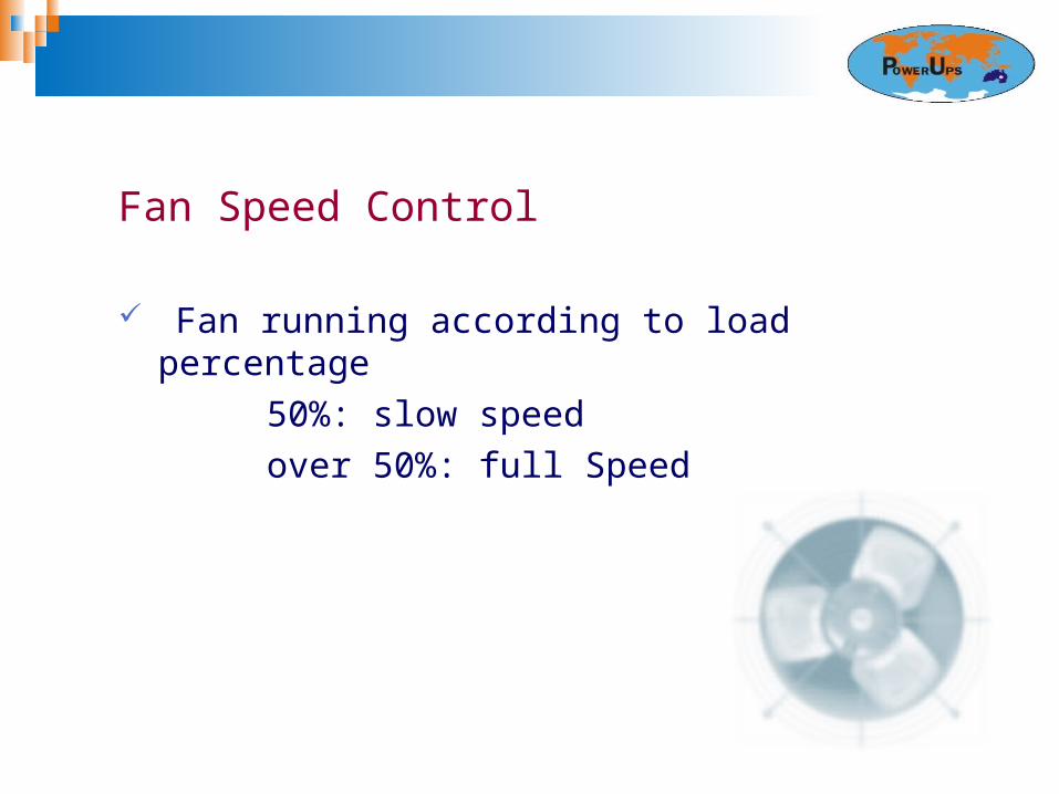
Fan Speed Control
Fan running according to load percentage 50%: slow speed over 50%: full Speed

Battery Temperature Compensation Auto-adjusted without any human involvement Compensate from 20 C: Reduce 0.001V*6 of floating voltage per 1 C. 0.002~0.006V * 6 per 1 C settable
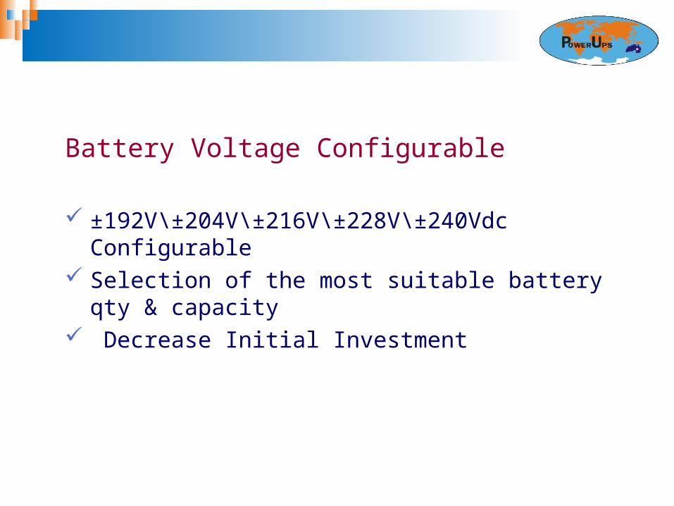
Battery Voltage Configurable ±192V\±204V\±216V\±228V\±240Vdc Configurable Selection of the most suitable battery qty & capacity Decrease Initial Investment
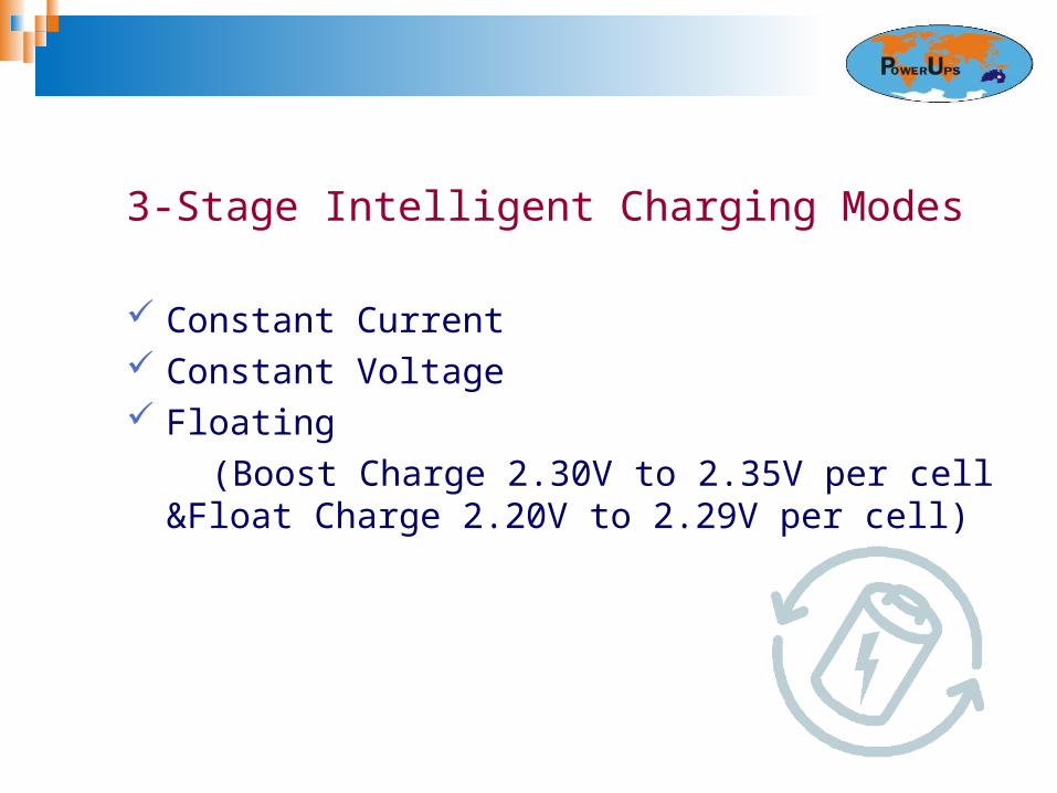
3-Stage Intelligent Charging Modes
Constant Current Constant Voltage Floating (Boost Charge 2.30V to 2.35V per cell &Float Charge 2.20V
to 2.29V per cell)

1. Summary
2. Appearance
3. Display
4. Principle
5. Supplement
6. Communication
7. Specification

Versatile Communication Interfaces
RS485 Ports RS232 Port USB port (for 100-500k) Parallel Port Dry contact SNMP slot
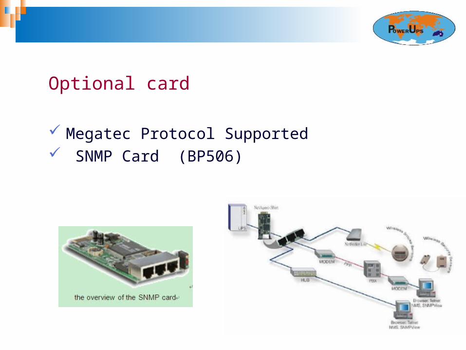
Optional card
Megatec Protocol Supported SNMP Card (BP506)
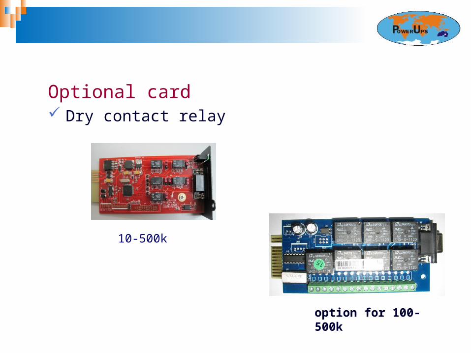
Optional card Dry contact relay
10-500k
option for 100-500k

Monitoring software (Muser4000)

1. Summary
2. Appearance
3. Display
4. Principle
5. Supplement
6. Communication
7. Specification