power related considerations in rf, microwave and high
TRANSCRIPT

Copyright © 2018 Picotest.com. All Rights Reserved. 3/21/2019
Better Products Through Better Test
Steve Sandler
Power Related Considerations in RF,
Microwave and High-Speed Circuits

Copyright © 2018 Picotest.com. All Rights Reserved. 3/21/20192
And Just a Bit About Steve
• 40+ Years Experience (1977-present)
• AEi Systems – Founder and CTO (1995-)
• Picotest – Founder and Managing Director (2010-)
• Test Engineer of the Year (2012-2014)
• Experience: Space Shuttle, Space Station, GPS, Large Hadron
Collider and many other military and commercial projects
• Primarily focused on RF, Analog, and Distributed Power Systems
lecturingwriting
making pizzalab time
I enjoy
Copyright © 2018 Picotest.com. All Rights Reserved. 3/21/20193
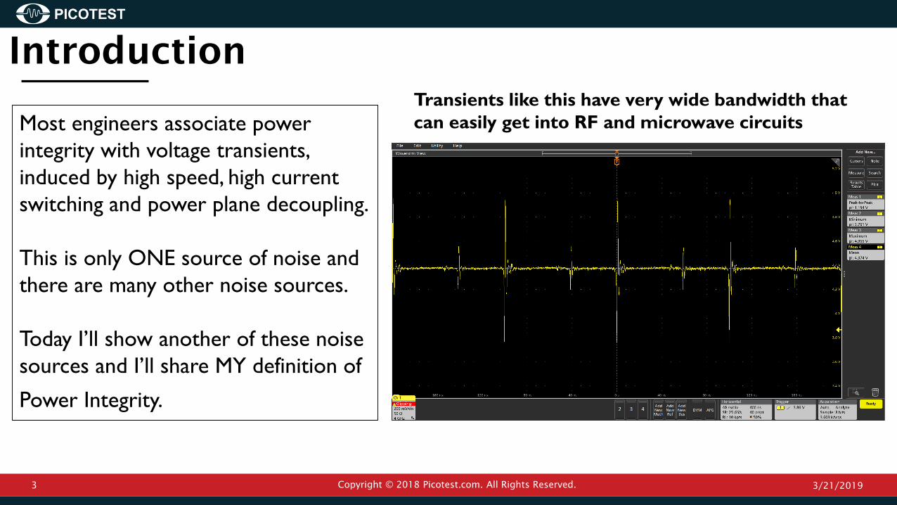
Most engineers associate power
integrity with voltage transients,
induced by high speed, high current
switching and power plane decoupling.
This is only ONE source of noise and
there are many other noise sources.
Today I’ll show another of these noise
sources and I’ll share MY definition of
Power Integrity.
Introduction
Transients like this have very wide bandwidth that
can easily get into RF and microwave circuits
Copyright © 2018 Picotest.com. All Rights Reserved. 3/21/20194
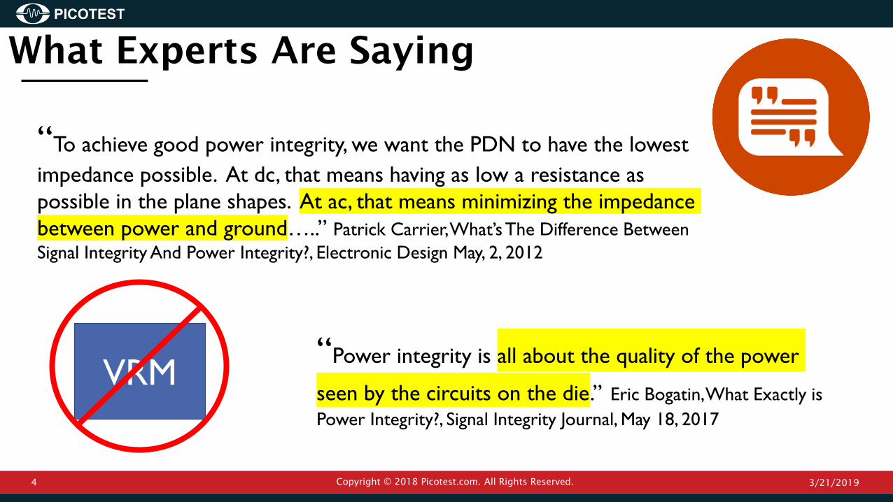
“Power integrity is all about the quality of the power
seen by the circuits on the die.” Eric Bogatin, What Exactly is
Power Integrity?, Signal Integrity Journal, May 18, 2017
VRM
“To achieve good power integrity, we want the PDN to have the lowest
impedance possible. At dc, that means having as low a resistance as
possible in the plane shapes. At ac, that means minimizing the impedance
between power and ground…..” Patrick Carrier, What’s The Difference Between
Signal Integrity And Power Integrity?, Electronic Design May, 2, 2012
What Experts Are Saying

Copyright © 2018 Picotest.com. All Rights Reserved. 3/21/20195
This Photo by Unknown Author is licensed under CC BY-NC-ND
We could agree to
disagree, but that
won’t result in a path
to success
We All Disagree

Copyright © 2018 Picotest.com. All Rights Reserved. 3/21/20196
Today I’ll share my
own definition and
hopefully convince
you that Power
Integrity is an
ecosystem that every
engineer contributes
to…. either in a good
way or in a bad way
Demo Board

Copyright © 2018 Picotest.com. All Rights Reserved. 3/21/20197
Switching
POL
Regulator
Linear
LDO
Regulator
125MHz
Clock
ON-OFF-ON
Noiseless
Power
Power Integrity Ecosystem

Copyright © 2018 Picotest.com. All Rights Reserved. 3/21/20198
VRM Contributes to Phase Noise and Jitter
Three different
power supplies,
powering the same
oscillator, show the
significant
contribution of the
power supply to
the RF output

Copyright © 2018 Picotest.com. All Rights Reserved. 3/21/20199
Switching Frequency Jitter Contributes
to the Phase Noise!
~ ൗ1𝑛𝑉𝐻𝑧
~2𝑢𝑉𝑝𝑝
~ ൗ350𝑛𝑉𝐻𝑧
~200𝑢𝑉𝑝𝑝
~ ൗ1𝑢𝑉𝐻𝑧
~1𝑚𝑉𝑝𝑝
2.8MHz Switching Frequency
VRM Contributes to Jitter
Copyright © 2018 Picotest.com. All Rights Reserved. 3/21/201910
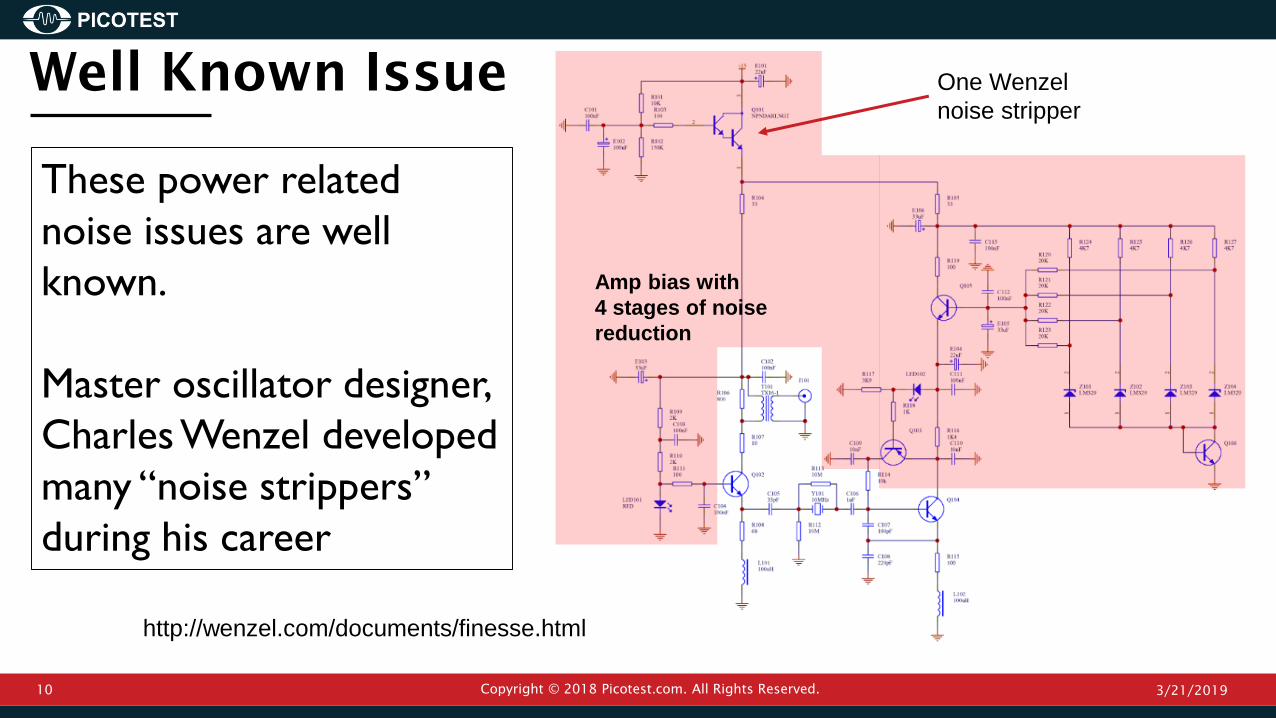
Well Known Issue
Amp bias with
4 stages of noise
reduction
These power related
noise issues are well
known.
Master oscillator designer,
Charles Wenzel developed
many “noise strippers”
during his career
http://wenzel.com/documents/finesse.html
One Wenzel
noise stripper

Ultra-low-noise voltage regulators are
an option, available from several
manufacturers
They require many capacitors, taking a
lot of PCB area and they are
expensive
RF Ultra-Low Noise Voltage Regulators
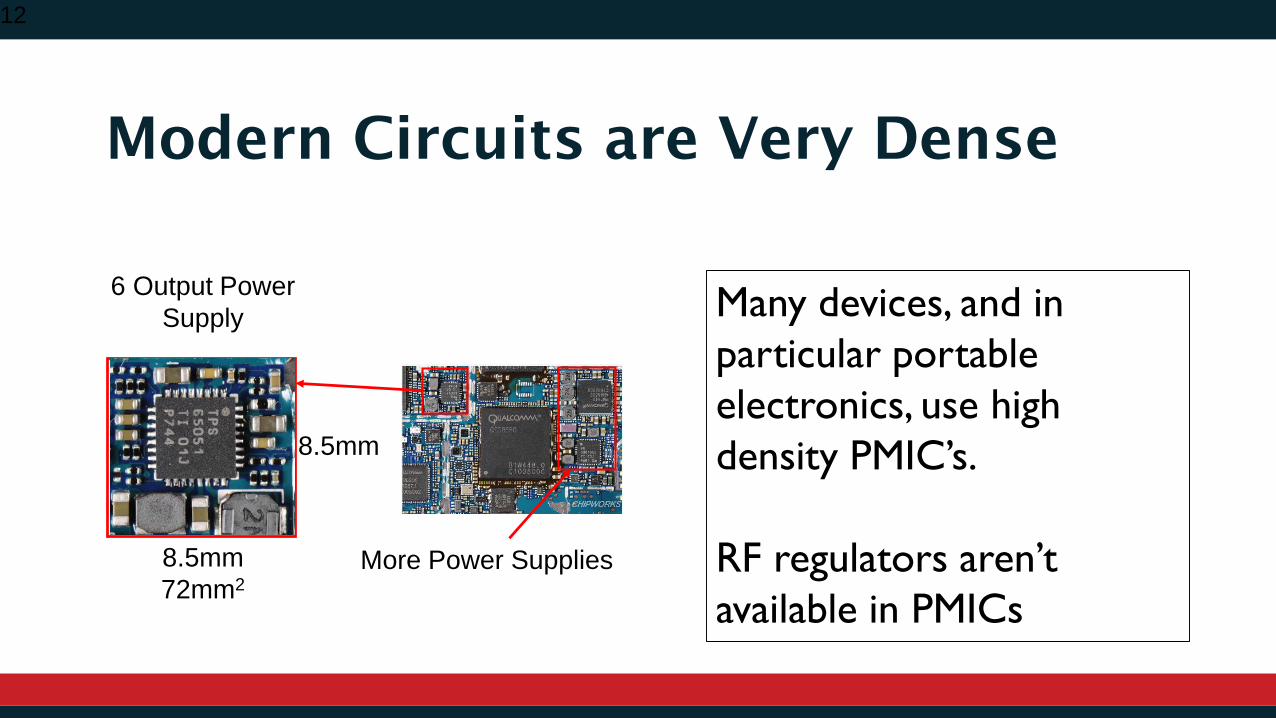
Modern Circuits are Very Dense
12
8.5mm
More Power Supplies8.5mm
72mm2
6 Output Power
Supply Many devices, and in
particular portable
electronics, use high
density PMIC’s.
RF regulators aren’t
available in PMICs

Copyright © 2018 Picotest.com. All Rights Reserved. 3/21/201913
Impedance Resonances Cause Spurs
Power supply
impedance peaks are
the most common
source of spurs.

Copyright © 2018 Picotest.com. All Rights Reserved. 3/21/201914
Impedance Measurement is a Great Tool
Here you can see
the 6MHz power
supply impedance
resonance that cause
the spurs
https://www.signalintegrityjournal.com/articles/
573-designing-power-for-sensitive-circuits

Copyright © 2018 Picotest.com. All Rights Reserved. 3/21/201915
A resistor is often the
simplest way to minimize
these spurs.
A 2.49Ω series resistor
eliminated the impedance
peak and eliminated the
6MHz spur
Flat Impedance Profile and Phase Noise
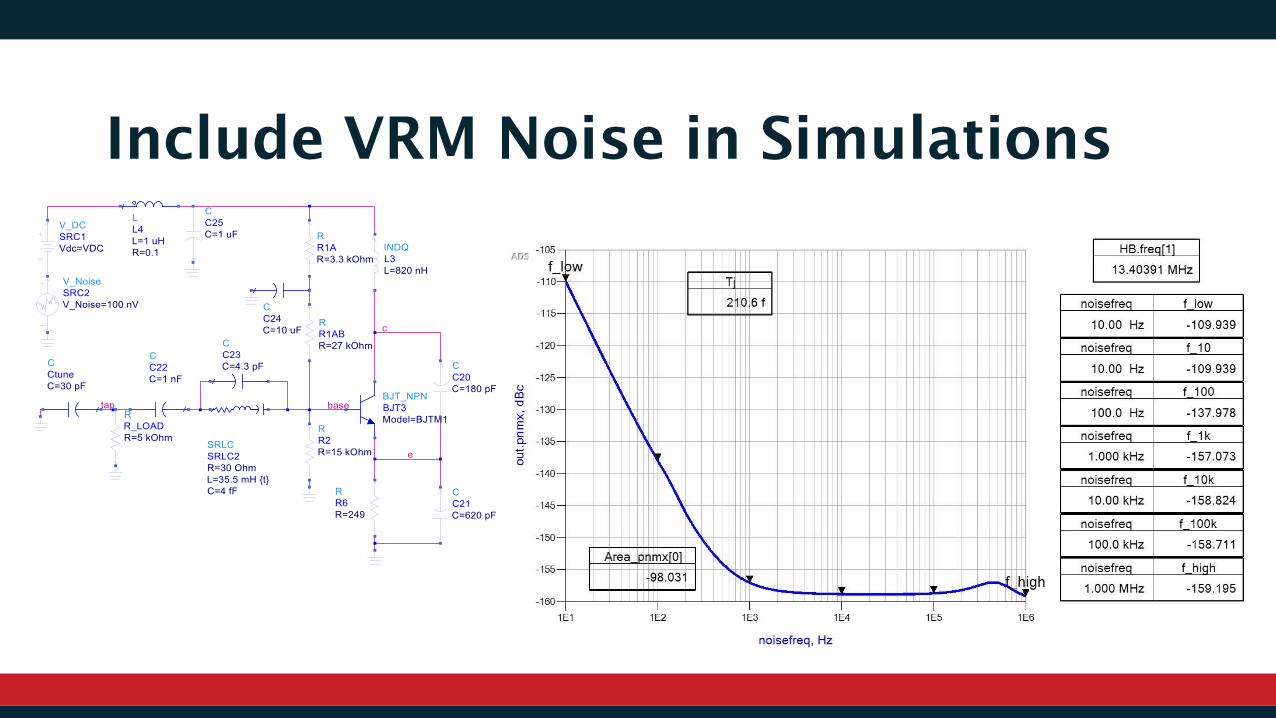
Include VRM Noise in Simulations
Copyright © 2018 Picotest.com. All Rights Reserved. 3/21/201917
• Different VRMs produced different jitter
• Some Jitter was NOT related to power supply impedance, but due to regulator noise voltage
• The voltage regulator includes internally generated expected noise
• The voltage regulator may also include internally generated unexpected noise
• Creating a lower impedance power rail can increase the noise at a spur, which can corrected by
increasing the impedance confirming that we don’t want the lowest AC impedance
• Including power supply noise in simulations is an efficient way to assess power integrity issues
What I demonstrated here:

Copyright © 2018 Picotest.com. All Rights Reserved. 3/21/201918
Power Integrity is a complete ecosystem,
dedicated to providing appropriate power
to all load devices, without degrading
other system performance. This is
inclusive of all noise sources, both
expected and unexpected. -Steve Sandler 2019

Copyright © 2018 Picotest.com. All Rights Reserved. 3/21/201919
Please feel free to:
• Connect with me on Linkedin
• Contact me directly at [email protected]
• Visit www.picotest.com/blog to learn more
• Look for my next book Power Integrity with ADS