post-processor (ppg) decoded documents/2019/mecsoft-cam-ppg... · post-processor definition file...
TRANSCRIPT
Post-Processor(PPG) Decoded
Published: May 2019
ALL 2019 Desktop Plugins
MecSoft Corpotation© Copyright 1998-2019
2019 Post Processor (PPG) Decoded
by MecSoft Corporation
________________________________________________________________________________________________________________________________________________________________________________________________________________________________________________________________________________________________________________________________________________________________________________________________________________________________________________________________________________________________________________________________________________________________________________________________________________________________________________________________
User Notes:
2Contents
2
© 2019 MecSoft Corporation
Table of Contents
Introduction 3
What is a Post-Processor? 5
What is the PPG? 6
PPG Variables & Macros 7
Decoding a Sample G-Code File 8
................................................................................................................................... 81 The Setup & Post Processor
................................................................................................................................... 82 The Sample Toolpaths
................................................................................................................................... 103 The Posted Setup G-Code File
................................................................................................................................... 144 The 2½ Axis Profiling Operation G-Code
................................................................................................................................... 175 The 2½ Axis Hole Profiling Operation G-Code
................................................................................................................................... 196 The Deep Drilling Operation G-Code
The Post-Processor Generator Dialog 22
................................................................................................................................... 221 PPG > General
................................................................................................................................... 232 PPG > Start/End
................................................................................................................................... 263 PPG > Tool Change
................................................................................................................................... 294 PPG > Setup
................................................................................................................................... 305 PPG > Spindle
................................................................................................................................... 326 PPG > Feed Rate
................................................................................................................................... 347 PPG > Motion
................................................................................................................................... 358 PPG > Circle
................................................................................................................................... 389 PPG > Helical/Spiral
................................................................................................................................... 4010 PPG > Multi Axis Motion
................................................................................................................................... 4111 PPG > Cutter Compensation
................................................................................................................................... 4512 PPG > Cut Motion Start/End
................................................................................................................................... 4613 PPG > Cycles
................................................................................................................................... 4914 PPG > Misc
................................................................................................................................... 5115 PPG > Variables
Index 52

2019 Post Processor (PPG) Decoded3
© 2019 MecSoft Corporation
Introduction
This guide provides the basis for understanding how the PPG operates and how you can useit to customize your posted g-code files. It uses a simple part file example with three toolpathoperations. Each toolpath is illustrated, examined and the resulting G-Code is color coded tothe portion of the PPG that controls it. Each section of the PPG is then explained andexamined for the part file example and its resulting G-Code.
NOTE: This guide includes sample CAM files,toolpath operations, a customized haas post
definition file and the sample G-Code file. Thesesource files are included in your CAMJam downloadarchive.
CAMJam Download Archive
Remember: The PPG is your friend! It can saveyou and your CNC operator enormous amounts
of time during production!
Introduction 4
© 2019 MecSoft Corporation
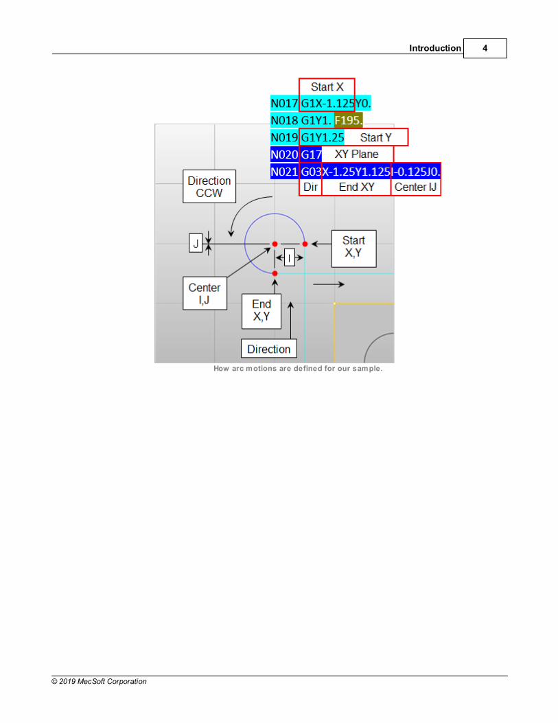
How arc motions are defined for our sample.
2019 Post Processor (PPG) Decoded5
© 2019 MecSoft Corporation
What is a Post-Processor?
The post-processor converts the toolpath operations you create in MecSoft CAM into asuitable format (called G-Code) that your CNC machine controller can interpret. The G-Codethat MecSoft CAM’s post-processors create adheres to ISO6983 (the international standardfor numerical controls). The post-processor also tailors the G-Code to a specific type of CNCcontroller such as Haas, Fanuc, Mach3, WinCNC, etc. MecSoft’s CAM plugins comeinstalled with over 300 post-processor definition files that are pre-configured for a wide rangeof CNC machines & controllers available on the market today.
What is the PPG? 6
© 2019 MecSoft Corporation
What is the PPG?
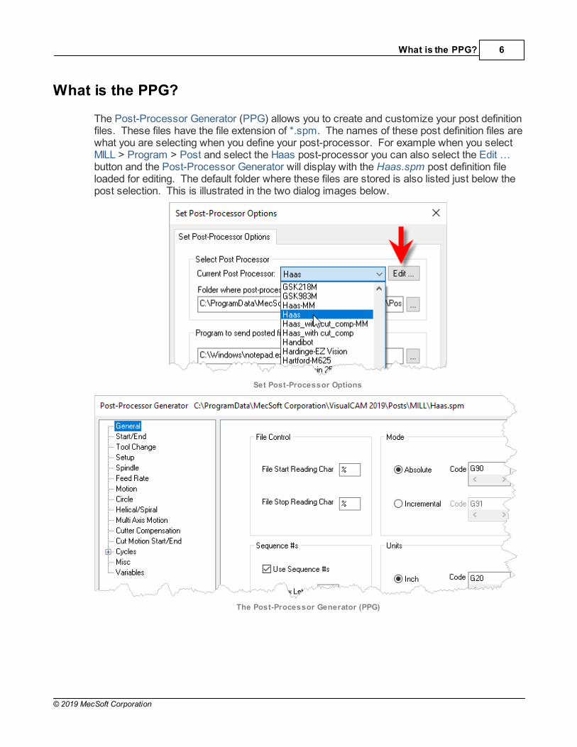
The Post-Processor Generator (PPG) allows you to create and customize your post definitionfiles. These files have the file extension of *.spm. The names of these post definition files arewhat you are selecting when you define your post-processor. For example when you selectMILL > Program > Post and select the Haas post-processor you can also select the Edit …button and the Post-Processor Generator will display with the Haas.spm post definition fileloaded for editing. The default folder where these files are stored is also listed just below thepost selection. This is illustrated in the two dialog images below.
Set Post-Processor Options
The Post-Processor Generator (PPG)

2019 Post Processor (PPG) Decoded7
© 2019 MecSoft Corporation
PPG Variables & Macros
The PPG uses hundreds of variables and macros that allow you to customize each postdefinition file. The names of the variables are pre-defined. The values for many of thevariables are extracted from your CAM cutting tools, setups, toolpath operations, etc. Othervariable values are defined within the PPG itself specific to the post definition file. Load thePPG and select Variables to see the complete name and value of each available variable. You can also use algebraic expressions within the PPG. Just pick the Help button from thePPG dialog to learn more.
Decoding a Sample G-Code File 8
© 2019 MecSoft Corporation
Decoding a Sample G-Code File
In this guide we will use the following sample part and toolpaths to see how internal variablesfor CAM definitions such as stock size, tool size, feeds & speeds parameters, toolpathoperation types and various other cutting parameters, are used by the post-processorgenerator and the post definition file to define the format and output of the resulting G-Codefile.
5.1 The Setup & Post Processor
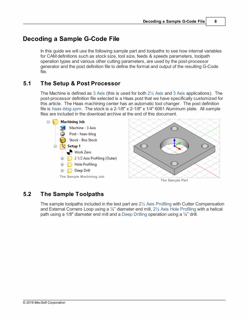
The Machine is defined as 3 Axis (this is used for both 2½ Axis and 3 Axis applications). Thepost-processor definition file selected is a Haas post that we have specifically customized forthis article. The Haas machining center has an automatic tool changer. The post definitionfile is haas-blog.spm. The stock is a 2-1/8" x 2-1/8" x 1/4" 6061 Aluminum plate. All samplefiles are included in the download archive at the end of this document.
The Sample Machining JobThe Sample Part
5.2 The Sample Toolpaths
The sample toolpaths included in the test part are 2½ Axis Profiling with Cutter Compensationand External Corners Loop using a ¼” diameter end mill, 2½ Axis Hole Profiling with a helicalpath using a 1/8" diameter end mill and a Deep Drilling operation using a ¼” drill.
2019 Post Processor (PPG) Decoded9
© 2019 MecSoft Corporation
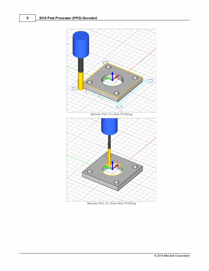
Sample Part: 2½ Axis Profiling
Sample Part: 2½ Axis Hole Profiling

Decoding a Sample G-Code File 10
© 2019 MecSoft Corporation
Sample Part: Deep Drilling
5.3 The Posted Setup G-Code File
PPG Dialog Selections
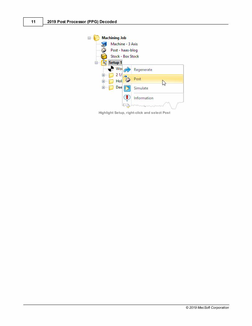
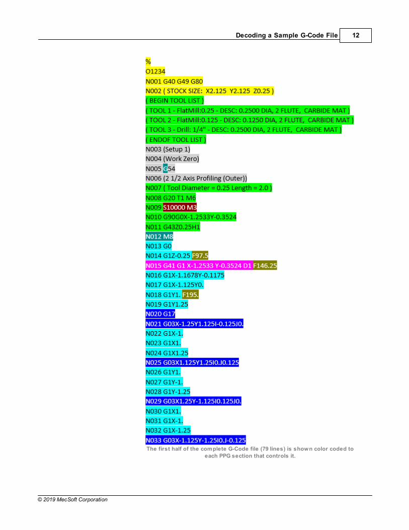
We right-clicked on the Setup and selected Post to output one G-Code file that includes all three machining operations. The G-Code file is shown below. We have color-coded each line of theG-Code file to its corresponding section in the PPG.
The PPG we have selected (haas-blog.spm) directs the formatand content of code. Using these three toolpaths you see that inthe 70 lines of code 12 of the 15 PPG sections are workingtogether to define the G-Code file. The PPG sections are shown inthe image below. Again, we have color-coded each section to helpyou identify each line in the G-Code file.
Three PPG sections are not represented in this G-Code sample. They are listed below along with the reason why. However thesesections are discussed is this article.
1. Setup: This is used for 4 and 5 Axis setups only. It doesnot affect our G-Code sample file.
2. Multi-Axis Motion: Again, this is used for 4 and 5 Axis setups only. It does not affectour G-Code sample file.
3. Cut Motion Start/End: This PPG section is not required for our G-Code sample file.
2019 Post Processor (PPG) Decoded11
© 2019 MecSoft Corporation
Highlight Setup, right-click and select Post
Decoding a Sample G-Code File 12
© 2019 MecSoft Corporation
The first half of the complete G-Code file (79 lines) is shown color coded to
each PPG section that controls it.
2019 Post Processor (PPG) Decoded13
© 2019 MecSoft Corporation
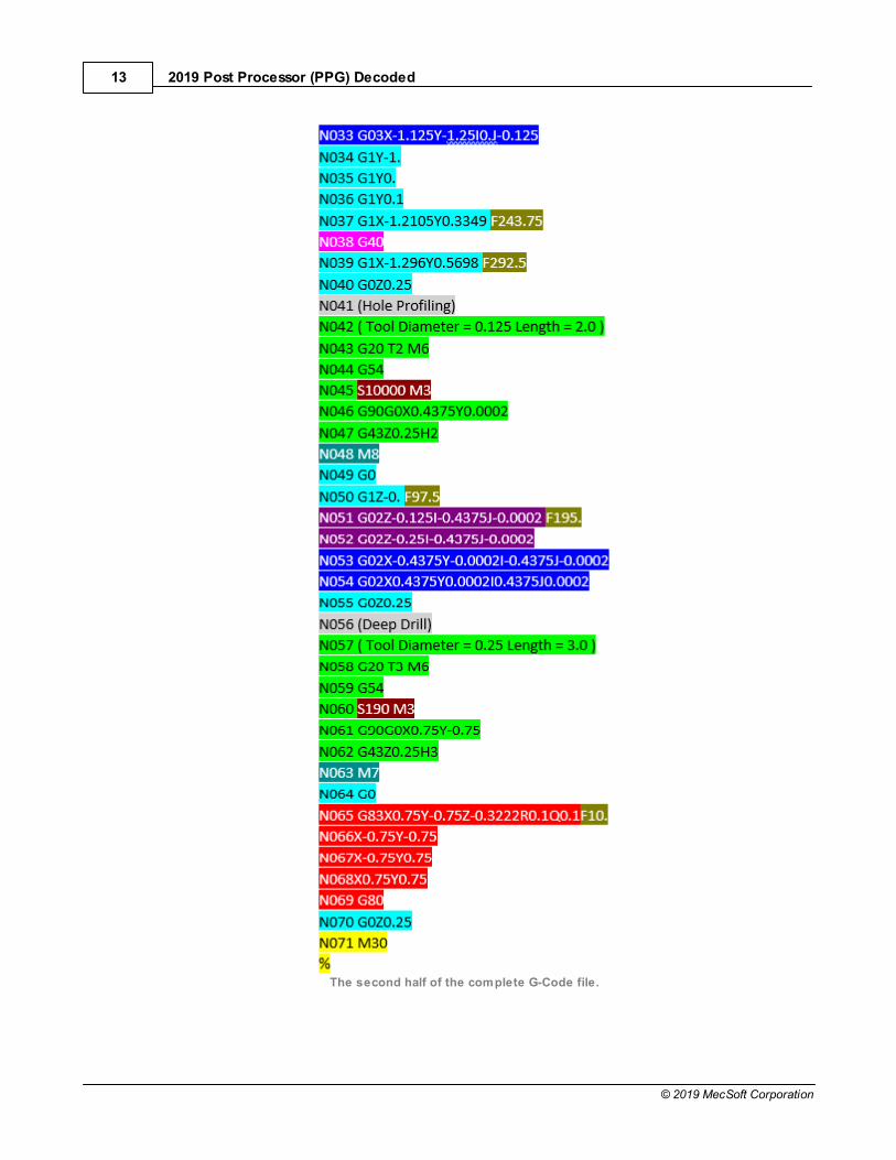
The second half of the complete G-Code file.

Decoding a Sample G-Code File 14
© 2019 MecSoft Corporation
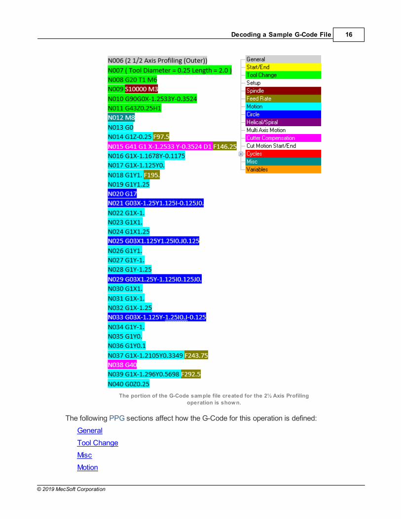
5.4 The 2½ Axis Profiling Operation G-Code
This toolpath strategy has Compensation enabled, a Climb Cut Direction and linear entry andexit motions. It also has External Corner Type set to Loop from the Cornering Parameterstab. With the Fit Arcs option enabled from the Advanced Cut Parameters tab, the four cornerloops are automatically converted to arc motions, shown in dark blue in the illustration below.
The 2½ Axis Profiling Cut Parameters

2019 Post Processor (PPG) Decoded15
© 2019 MecSoft Corporation
The 2½ Axis Profiling Operation and G-Code
Decoding a Sample G-Code File 16
© 2019 MecSoft Corporation
The portion of the G-Code sample file created for the 2½ Axis Profiling
operation is shown.
The following PPG sections affect how the G-Code for this operation is defined:
General
Tool Change
Misc
Motion

2019 Post Processor (PPG) Decoded17
© 2019 MecSoft Corporation
Cutter Compensation
Cycles
5.5 The 2½ Axis Hole Profiling Operation G-Code
This toolpath strategy is defined by a helical motion. Because Hole Depth is set to 0.25 andthe Helix Pitch Height is set to 0.125, a total of two helical motions are required. The optionsto Create full (360 degree) helixes only and Output each helix individually are enabled. TheCut Direction is set to Conventional (Up Cutting).
The 2½ Axis Hole Profiling Operation Cut Parameters

Decoding a Sample G-Code File 18
© 2019 MecSoft Corporation
The 2½ Axis Hole Profiling toolpath has a Clockwise spindle direction and a Convention (Up Cutting) Cut
Direction. Two full 360 degree helical motions are created. At the bottom of the hole profile two 180 degree
arc motions are defined.
The portion of the G-Code sample file created for the 2½ Axis Hole Profiling
operation is shown.
The following PPG sections affect how the G-Code for this operation is defined:
General
Tool Change
Misc
Motion
Helical/Spiral
Circle

2019 Post Processor (PPG) Decoded19
© 2019 MecSoft Corporation
Cycles
5.6 The Deep Drilling Operation G-Code
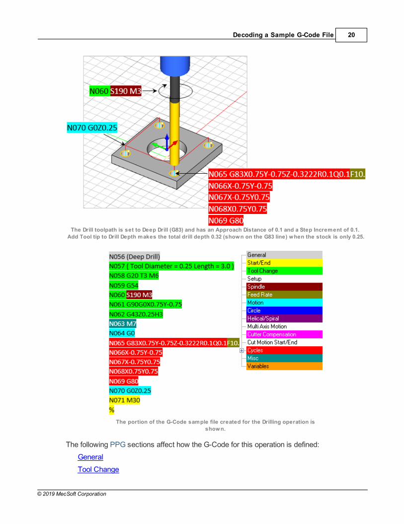
This toolpath strategy is defined by a Drill cycle. The Hole Depth is set to 0.25. The Drill Typeis set to Deep Drill. This enables the Step Increment option which is set to 0.1 creating threedrill increments for each of the four holes (i.e., the drill will peck down three times to completeone hole). We have also enabled Add Tool tip to Drill Depth. This ensures a thru hole bytaking into account the tip angle of the tool when calculating the drill depth. Minimum DistanceSort is also selected from the Sorting tab determining the fastest drill sequence.
The Cut Parameters tab for the Drilling operation.
Decoding a Sample G-Code File 20
© 2019 MecSoft Corporation
The Drill toolpath is set to Deep Drill (G83) and has an Approach Distance of 0.1 and a Step Increment of 0.1.
Add Tool tip to Drill Depth makes the total drill depth 0.32 (shown on the G83 line) when the stock is only 0.25.
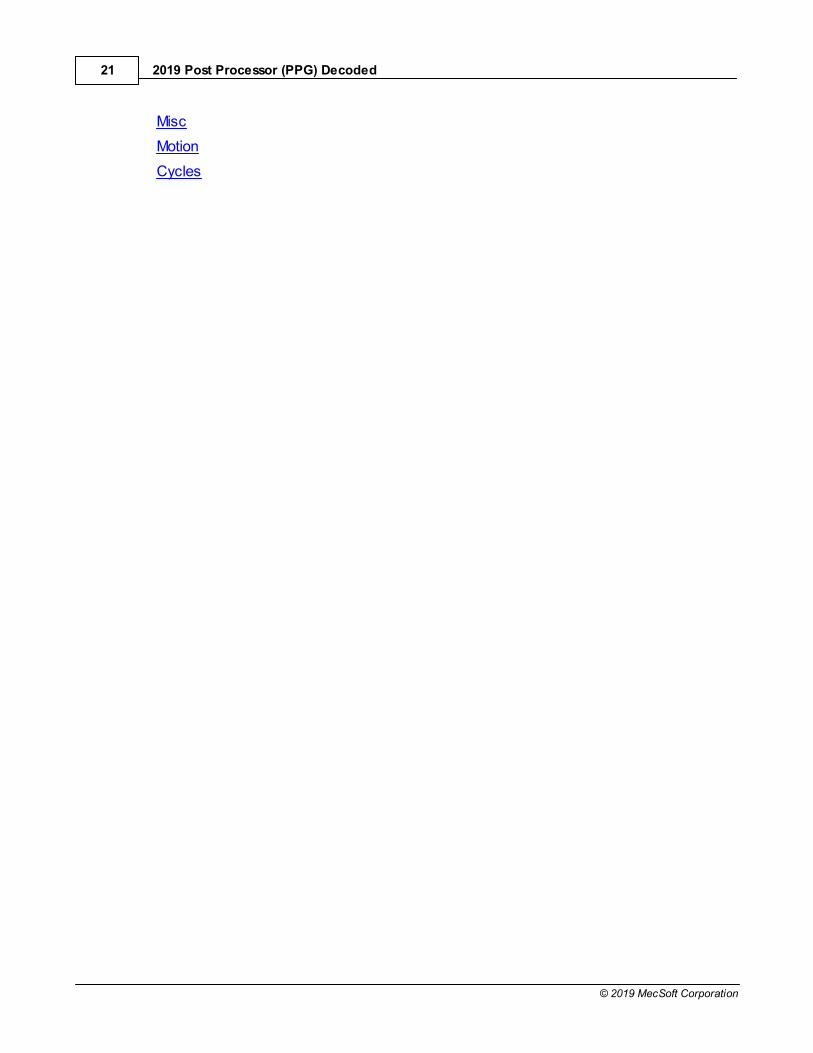
The portion of the G-Code sample file created for the Drilling operation is
shown.
The following PPG sections affect how the G-Code for this operation is defined:
General
Tool Change
2019 Post Processor (PPG) Decoded21
© 2019 MecSoft Corporation
Misc
Motion
Cycles

The Post-Processor Generator Dialog 22
© 2019 MecSoft Corporation
The Post-Processor Generator Dialog
The topics below show you how our sample post (haas-blog.spm) is defined within the PPG. We began with the standard haas.spm post definition file and added a few changes andcustomizations. ALL of the customizations were performed using the PPG dialog. Thesample G-Code file was not edited or formatted manually except for adding our color-codes. We added the colors to make it easier for you to follow this article and better understand howthe different PPG sections work together to produce the G-Code.
6.1 PPG > General
The General section of the PPG includes options that affect the entire G-Code file. Modes areset, Units are defined, Comments are enabled, Sequence #s are enabled and defined, alongwith other formatting options. The Modal Output check boxes determine if values arerepeated on every line or only when the value changes.
This is the color code for the General section.
The General section of the Post-Processor Generator (PPG) dialog for our haas-blog.spm post definition file.
Resulting G-Code Sample
2019 Post Processor (PPG) Decoded23
© 2019 MecSoft Corporation
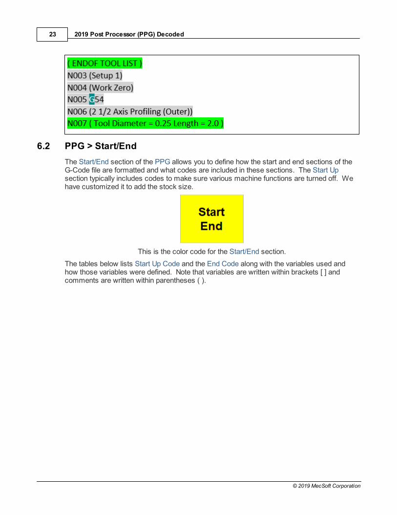
6.2 PPG > Start/End
The Start/End section of the PPG allows you to define how the start and end sections of theG-Code file are formatted and what codes are included in these sections. The Start Upsection typically includes codes to make sure various machine functions are turned off. Wehave customized it to add the stock size.
This is the color code for the Start/End section.
The tables below lists Start Up Code and the End Code along with the variables used andhow those variables were defined. Note that variables are written within brackets [ ] andcomments are written within parentheses ( ).
The Post-Processor Generator Dialog 24
© 2019 MecSoft Corporation
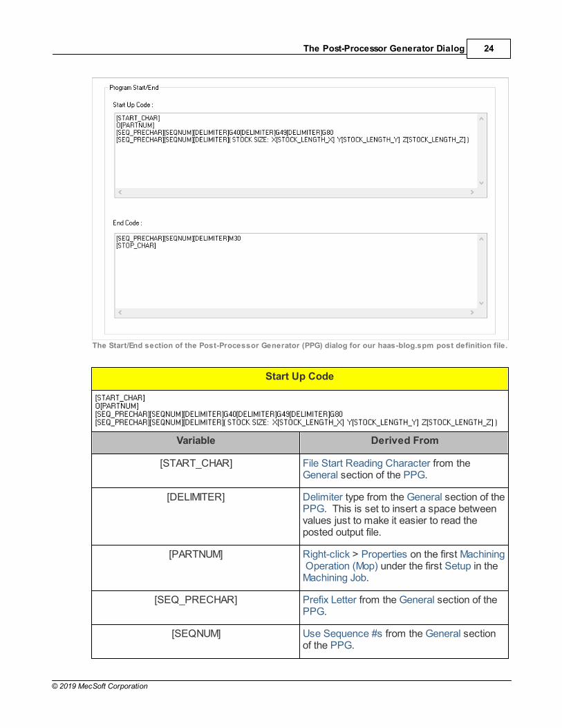
The Start/End section of the Post-Processor Generator (PPG) dialog for our haas-blog.spm post definition file.
Start Up Code
Variable Derived From
[START_CHAR] File Start Reading Character from theGeneral section of the PPG.
[DELIMITER] Delimiter type from the General section of thePPG. This is set to insert a space betweenvalues just to make it easier to read theposted output file.
[PARTNUM] Right-click > Properties on the first Machining Operation (Mop) under the first Setup in theMachining Job.
[SEQ_PRECHAR] Prefix Letter from the General section of thePPG.
[SEQNUM] Use Sequence #s from the General sectionof the PPG.

2019 Post Processor (PPG) Decoded25
© 2019 MecSoft Corporation
[STOCK_LENGTH_X] MecSoft CAM > MILL > Machining Job >Stock > Length (L)
[STOCK_LENGTH_Y] MecSoft CAM > MILL > Machining Job >Stock > Width (W)
[STOCK_LENGTH_Z] MecSoft CAM > MILL > Machining Job >Stock > Height (H)
ISO Codes Function
G40 Cutter Compensation Off
G49 Tool Length Compensation Off
G80 Canned Cycle Off
Resulting G-Code Sample
End Code
Variable Derived From
[DELIMITER] Delimiter type from the General section of thePPG.
[SEQ_PRECHAR] Prefix Letter from the General section of thePPG.
[SEQNUM] Use Sequence #s from the General sectionof the PPG.
[STOP_CHAR] File Stop Reading Character from theGeneral section of the PPG.
ISO Codes Function
M30 End of Program

The Post-Processor Generator Dialog 26
© 2019 MecSoft Corporation
Resulting G-Code Sample
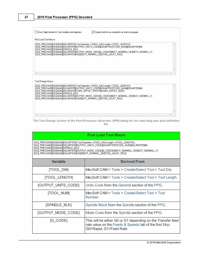
6.3 PPG > Tool Change
The Tool Change section of the PPG allows you to define the First Tool Load Macro and theTool Change Macro for subsequent tool changes. These macros define all of the informationyour CNC controller needs to load and change cutting tools and move the tool into position.
This is the color code for the Tool Change section.
This section is ignored if your CNC machine does not have an automatic tool changer. Thereason these are called Macros is because they use nested variables. For example[SPINDLE_BLK] is the result of the Spindle Block Format code defined in the Spindle sectionof the PPG.
First you will notice that Output tool list as comments at start of program is checked. Because Comments are enabled in the General section of the PPG, the following commentsare listed at the top of the G-Code file:
Output tool list as comments
Now onto the macros.
2019 Post Processor (PPG) Decoded27
© 2019 MecSoft Corporation
The Tool Change section of the Post-Processor Generator (PPG) dialog for our haas-blog.spm post definition
file.
First Load Tool Macro
Variable Derived From
[TOOL_DIA] MecSoft CAM > Tools > Create/Select Tool > Tool Dia.
[TOOL_LENGTH] MecSoft CAM > Tools > Create/Select Tool > Tool Length.
[OUTPUT_UNITS_CODE] Units Code from the General section of the PPG.
[TOOL_NUM] MecSoft CAM > Tools > Create/Select Tool > ToolNumber.
[SPINDLE_BLK] Spindle Block from the Spindle section of the PPG.
[OUTPUT_MODE_CODE] Mode Code from the Spindle section of the PPG.
[G_CODE] This will be either G0 or G1 depending on the Transfer feedrate value on the Feeds & Speeds tab of the first Mop. G0=Rapid, G1=Feed Rate
The Post-Processor Generator Dialog 28
© 2019 MecSoft Corporation
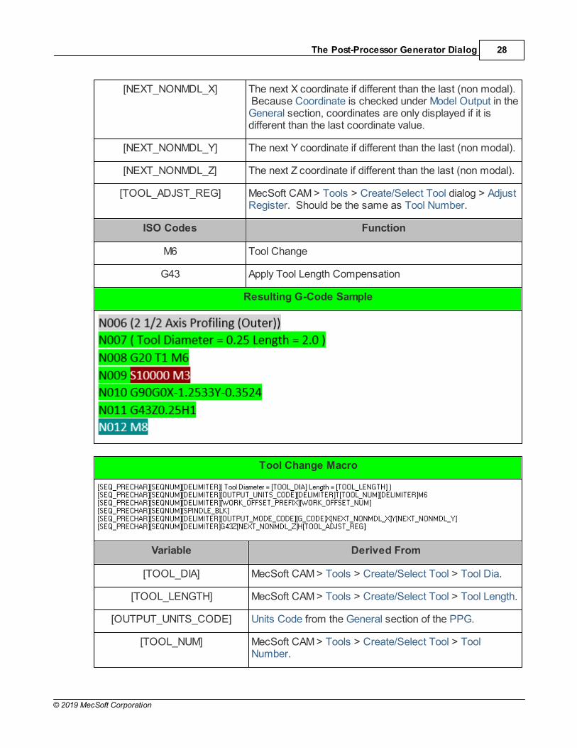
[NEXT_NONMDL_X] The next X coordinate if different than the last (non modal). Because Coordinate is checked under Model Output in theGeneral section, coordinates are only displayed if it isdifferent than the last coordinate value.
[NEXT_NONMDL_Y] The next Y coordinate if different than the last (non modal).
[NEXT_NONMDL_Z] The next Z coordinate if different than the last (non modal).
[TOOL_ADJST_REG] MecSoft CAM > Tools > Create/Select Tool dialog > AdjustRegister. Should be the same as Tool Number.
ISO Codes Function
M6 Tool Change
G43 Apply Tool Length Compensation
Resulting G-Code Sample
Tool Change Macro
Variable Derived From
[TOOL_DIA] MecSoft CAM > Tools > Create/Select Tool > Tool Dia.
[TOOL_LENGTH] MecSoft CAM > Tools > Create/Select Tool > Tool Length.
[OUTPUT_UNITS_CODE] Units Code from the General section of the PPG.
[TOOL_NUM] MecSoft CAM > Tools > Create/Select Tool > ToolNumber.

2019 Post Processor (PPG) Decoded29
© 2019 MecSoft Corporation
[WORK_OFFSET_PREFIX] Work Offset Code from the Misc section of the PPG.
[WORK_OFFSET_NUM] MecSoft CAM > Machining Job > Work Zero > Work OffsetRegister Number.
[SPINDLE_BLK] Spindle Block from the Spindle section of the PPG.
[OUTPUT_MODE_CODE] Mode Code from the Spindle section of the PPG.
[G_CODE] This will be either G0 or G1 depending on the Transferfeed rate value on the Feeds & Speeds tab of the first Mop. G0=Rapid, G1=Feed Rate
[NEXT_NONMDL_X] The next X coordinate if different than the last (non modal). Because Coordinate is checked under Model Output inthe General section, coordinates are only displayed if it isdifferent than the last coordinate value.
[NEXT_NONMDL_Y] The next Y coordinate if different than the last (non modal).
[NEXT_NONMDL_Z] The next Z coordinate if different than the last (non modal).
[TOOL_ADJST_REG] MecSoft CAM > Tools > Create/Select Tool dialog > AdjustRegister. Should be the same as Tool Number.
ISO Codes Function
M6 Tool Change
G43 Apply Tool Length Compensation
Resulting G-Code Sample
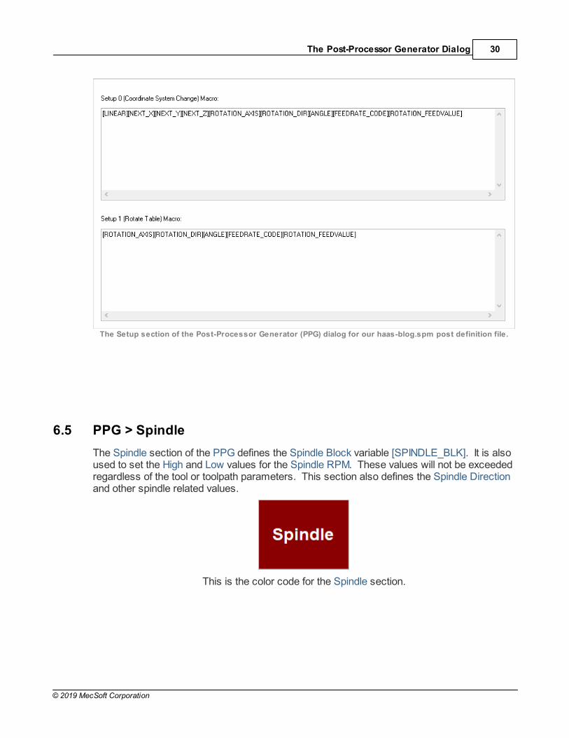
6.4 PPG > Setup
The Setup section of the PPG is only used if your Machine definition is set to 4 Axis or 5 Axis(MecSoft CAM > Machining Job > Machine). It is used to output the rotation axis and anglesfor the setup. This will be covered in a future guide.
The Post-Processor Generator Dialog 30
© 2019 MecSoft Corporation
The Setup section of the Post-Processor Generator (PPG) dialog for our haas-blog.spm post definition file.
6.5 PPG > Spindle
The Spindle section of the PPG defines the Spindle Block variable [SPINDLE_BLK]. It is alsoused to set the High and Low values for the Spindle RPM. These values will not be exceededregardless of the tool or toolpath parameters. This section also defines the Spindle Directionand other spindle related values.
This is the color code for the Spindle section.
2019 Post Processor (PPG) Decoded31
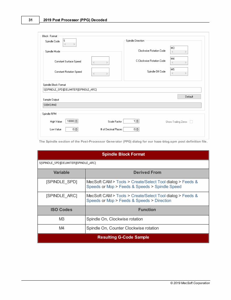
© 2019 MecSoft Corporation
The Spindle section of the Post-Processor Generator (PPG) dialog for our haas-blog.spm post definition file.
Spindle Block Format
Variable Derived From
[SPINDLE_SPD] MecSoft CAM > Tools > Create/Select Tool dialog > Feeds &Speeds or Mop > Feeds & Speeds > Spindle Speed
[SPINDLE_ARC] MecSoft CAM > Tools > Create/Select Tool dialog > Feeds &Speeds or Mop > Feeds & Speeds > Direction
ISO Codes Function
M3 Spindle On, Clockwise rotation
M4 Spindle On, Counter Clockwise rotation
Resulting G-Code Sample

The Post-Processor Generator Dialog 32
© 2019 MecSoft Corporation
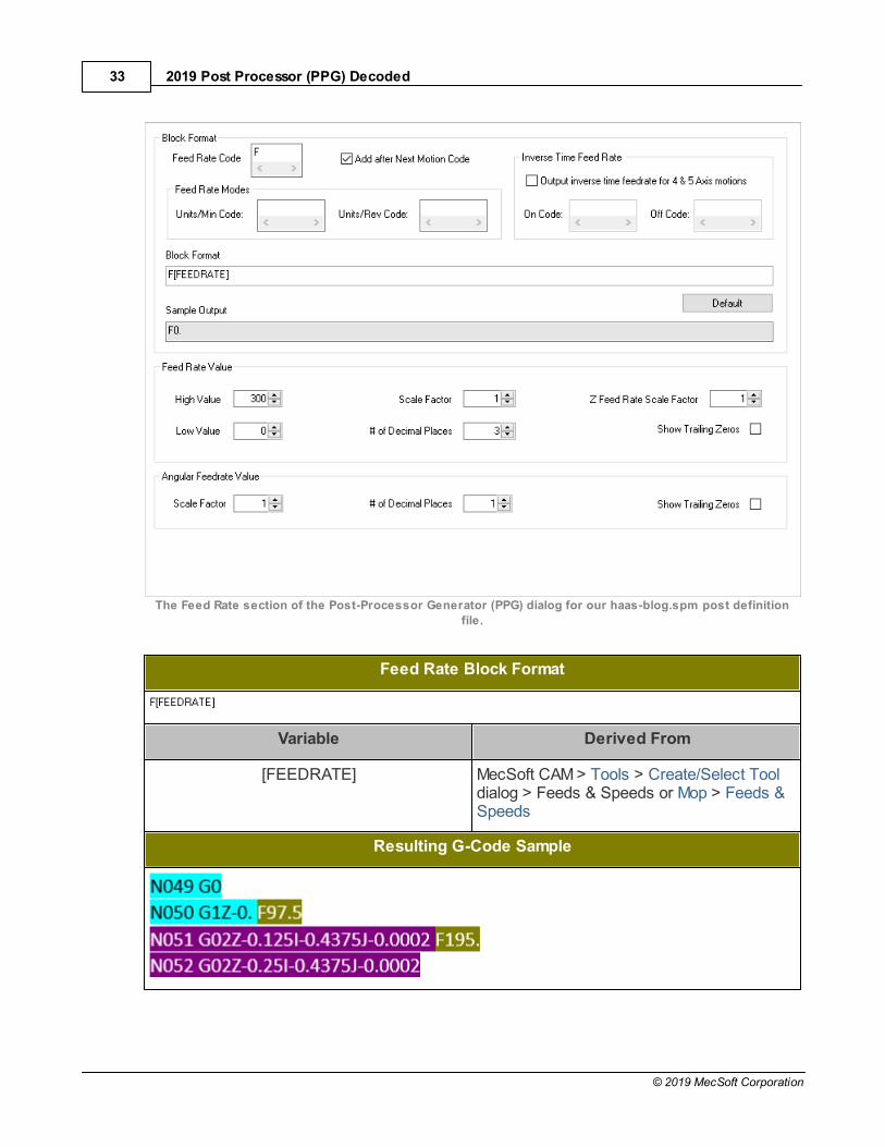
6.6 PPG > Feed Rate
The Feed Rate section of the PPG defines the block format for Feed Rate. The Feed RateBlock is inserted only when the feed rate changes if Feedrate is checked under Modal Outputin the General section of the PPG. You can also set the High and Low values for Feedratehere as well as other parameters related to feed rate.
This is the color code for the Feed Rate section.
2019 Post Processor (PPG) Decoded33
© 2019 MecSoft Corporation
The Feed Rate section of the Post-Processor Generator (PPG) dialog for our haas-blog.spm post definition
file.
Feed Rate Block Format
Variable Derived From
[FEEDRATE] MecSoft CAM > Tools > Create/Select Tooldialog > Feeds & Speeds or Mop > Feeds &Speeds
Resulting G-Code Sample

The Post-Processor Generator Dialog 34
© 2019 MecSoft Corporation
6.7 PPG > Motion
The Motion section of the PPG defines the Linear Motion and Rapid Motion Block Format. Anytime a linear or rapid motion is defined it is output in this format. This section also allowsyou to control other aspects of motion coordinates including X, Y and Z Scale Factors, # ofDecimal Places and more.
This is the color code for the Motion section.
The Motion section of the Post-Processor Generator (PPG) dialog for our haas-blog.spm post definition file.
Linear Motion Block Format
Rapid Motion Block Format
2019 Post Processor (PPG) Decoded35
© 2019 MecSoft Corporation
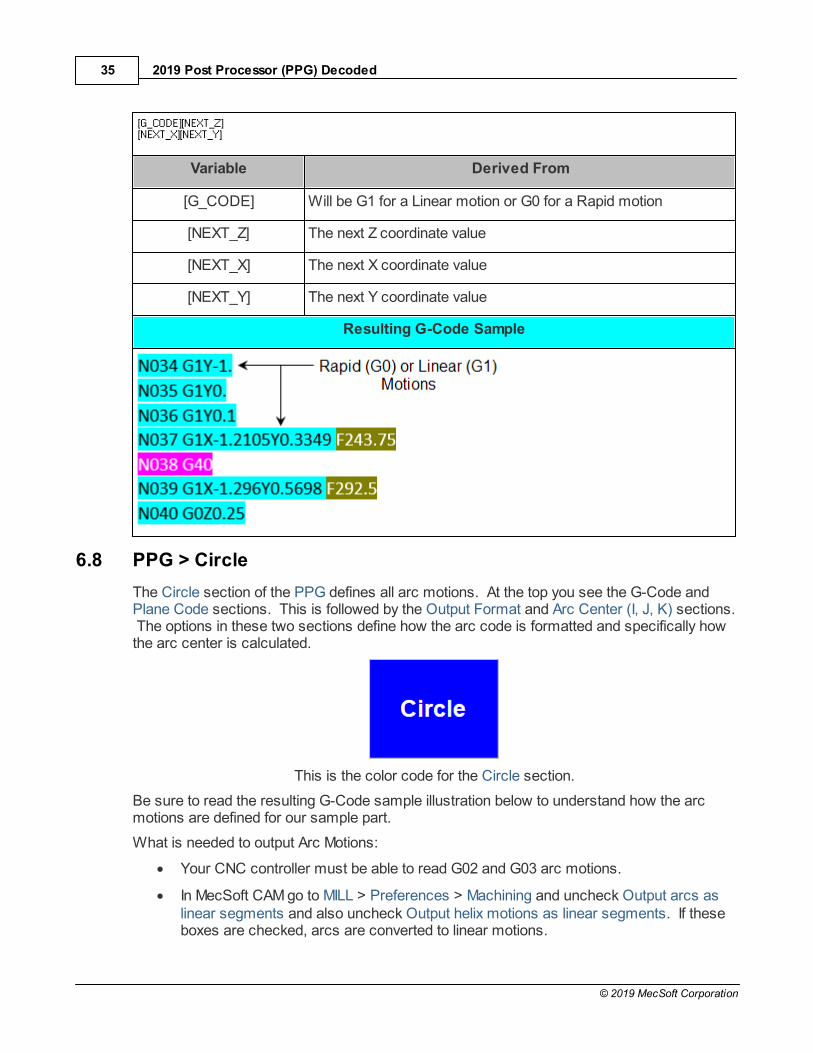
Variable Derived From
[G_CODE] Will be G1 for a Linear motion or G0 for a Rapid motion
[NEXT_Z] The next Z coordinate value
[NEXT_X] The next X coordinate value
[NEXT_Y] The next Y coordinate value
Resulting G-Code Sample
6.8 PPG > Circle
The Circle section of the PPG defines all arc motions. At the top you see the G-Code andPlane Code sections. This is followed by the Output Format and Arc Center (I, J, K) sections. The options in these two sections define how the arc code is formatted and specifically howthe arc center is calculated.
This is the color code for the Circle section.
Be sure to read the resulting G-Code sample illustration below to understand how the arcmotions are defined for our sample part.
What is needed to output Arc Motions:
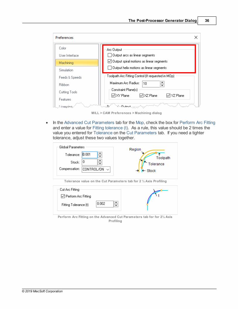
· Your CNC controller must be able to read G02 and G03 arc motions.
· In MecSoft CAM go to MILL > Preferences > Machining and uncheck Output arcs aslinear segments and also uncheck Output helix motions as linear segments. If theseboxes are checked, arcs are converted to linear motions.
The Post-Processor Generator Dialog 36
© 2019 MecSoft Corporation
MILL > CAM Preferences > Machining dialog
· In the Advanced Cut Parameters tab for the Mop, check the box for Perform Arc Fittingand enter a value for Fitting tolerance (t). As a rule, this value should be 2 times thevalue you entered for Tolerance on the Cut Parameters tab. If you need a tightertolerance, adjust these two values together.
Tolerance value on the Cut Parameters tab for 2 ½ Axis Profiling
Perform Arc Fitting on the Advanced Cut Parameters tab for for 2½ Axis
Profiling
2019 Post Processor (PPG) Decoded37
© 2019 MecSoft Corporation
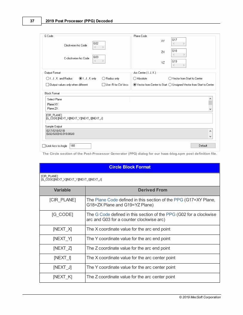
The Circle section of the Post-Processor Generator (PPG) dialog for our haas-blog.spm post definition file.
Circle Block Format
Variable Derived From
[CIR_PLANE] The Plane Code defined in this section of the PPG (G17=XY Plane,G18=ZX Plane and G19=YZ Plane)
[G_CODE] The G Code defined in this section of the PPG (G02 for a clockwisearc and G03 for a counter clockwise arc)
[NEXT_X] The X coordinate value for the arc end point
[NEXT_Y] The Y coordinate value for the arc end point
[NEXT_Z] The Z coordinate value for the arc end point
[NEXT_I] The X coordinate value for the arc center point
[NEXT_J] The Y coordinate value for the arc center point
[NEXT_K] The Z coordinate value for the arc center point
The Post-Processor Generator Dialog 38
© 2019 MecSoft Corporation
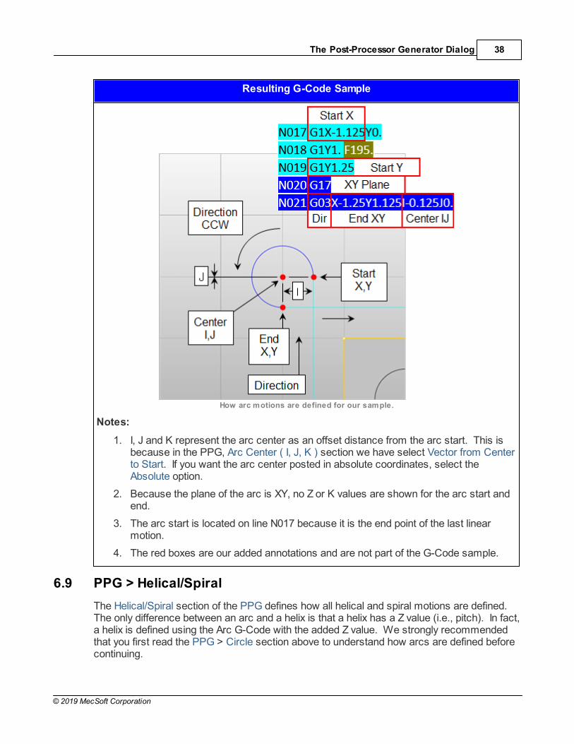
Resulting G-Code Sample
How arc motions are defined for our sample.
Notes:
1. I, J and K represent the arc center as an offset distance from the arc start. This isbecause in the PPG, Arc Center ( I, J, K ) section we have select Vector from Centerto Start. If you want the arc center posted in absolute coordinates, select theAbsolute option.
2. Because the plane of the arc is XY, no Z or K values are shown for the arc start andend.
3. The arc start is located on line N017 because it is the end point of the last linearmotion.
4. The red boxes are our added annotations and are not part of the G-Code sample.
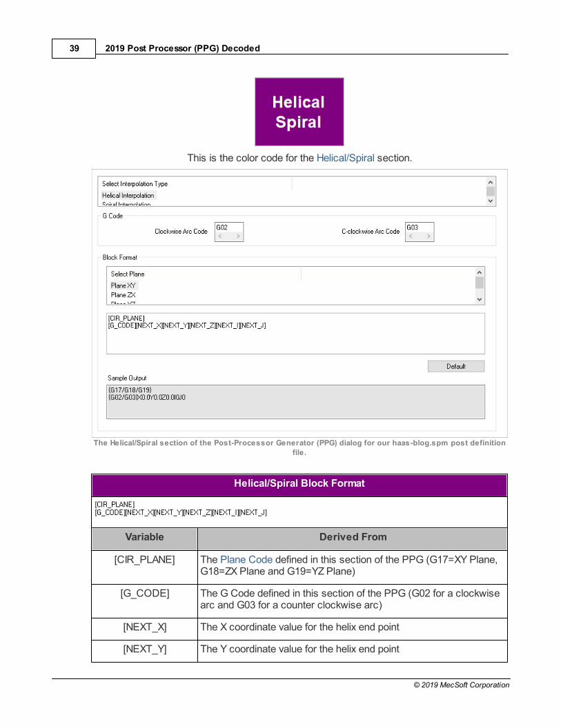
6.9 PPG > Helical/Spiral
The Helical/Spiral section of the PPG defines how all helical and spiral motions are defined. The only difference between an arc and a helix is that a helix has a Z value (i.e., pitch). In fact,a helix is defined using the Arc G-Code with the added Z value. We strongly recommendedthat you first read the PPG > Circle section above to understand how arcs are defined beforecontinuing.
2019 Post Processor (PPG) Decoded39
© 2019 MecSoft Corporation
This is the color code for the Helical/Spiral section.
The Helical/Spiral section of the Post-Processor Generator (PPG) dialog for our haas-blog.spm post definition
file.
Helical/Spiral Block Format
Variable Derived From
[CIR_PLANE] The Plane Code defined in this section of the PPG (G17=XY Plane,G18=ZX Plane and G19=YZ Plane)
[G_CODE] The G Code defined in this section of the PPG (G02 for a clockwisearc and G03 for a counter clockwise arc)
[NEXT_X] The X coordinate value for the helix end point
[NEXT_Y] The Y coordinate value for the helix end point

The Post-Processor Generator Dialog 40
© 2019 MecSoft Corporation
[NEXT_Z] The Z coordinate value for the helix end point
[NEXT_I] The X coordinate value for the helix center point
[NEXT_J] The Y coordinate value for the helix center point
[NEXT_K] The Z coordinate value for the arc center point
Resulting G-Code Sample
Notes:
1. Notice that the X, Y start of the helix is one line N046 and the Z start of the helix is online N050.
2. Lines N051 and N052 are the two helical motions. Notice that each includes a Zcoordinate value.
3. Line N051 create the first full helix starting a Z0 and ending at Z0.125.
4. Line N052 create the second full helix starting a Z0.125 and ending at Z0.25.
5. Lines N053 and N054 are the two arc motions located at the base of the hole. Together they form a complete circle which serves as a clean up pass.
6.10 PPG > Multi Axis Motion
The Multi Axis Motion section of the PPG is only used if your Machine definition is set to 4 Axisor 5 Axis (MecSoft CAM > Machining Job > Machine). It is used to define the Rotation AxisCode, Rotation Direction Code, Angle Value, and the Motion Block. This will be covered in afuture blog post.

2019 Post Processor (PPG) Decoded41
© 2019 MecSoft Corporation
The Multi Axis Motion section of the Post-Processor Generator (PPG) dialog for our haas-blog.spm post
definition file.
6.11 PPG > Cutter Compensation
The Cutter Compensation section of the PPG is used to provide a way to adjust the toolpathat the machine to compensate for tool size, tool wear, and tool deflection. The dialogprovides the block format for Cutter Compensation Left (G41), Cutter Compensation Right(G42) and Cutter Compensation Off (G40). G41 is used for a climb (down cut) direction witha clockwise (right-handed) spindle direction. G42 is used for a conventional (up cut) direction.
This is the color code for the Cutter Compensation section.
What is needed to output Cutter Compensation:
1. In the Cut Parameters tab under Global Parameters set Compensation to eitherAuto/On or Control/On. In our example, we have it set to Control/On.

The Post-Processor Generator Dialog 42
© 2019 MecSoft Corporation
Compensation is set to CONTROL/ON and Cut Direction is set to Climb
2. In the Cut Parameters tab set Cut Direction to either Climb or Conventional. Do notset it to Mixed as this will disable Cutter Compensation. In our example we have it setto Climb.
3. Your first cut motion must be linear. In our example, on the Entry/Exit tab of the 2½Axis Profiling Mop, Entry Motions is set to Lines & Arcs and the Engage Motion is setto Linear. Similarly, the Exit Motions is set to Lines & Arcs and the Retract Motion isset to Linear.

2019 Post Processor (PPG) Decoded43
© 2019 MecSoft Corporation
Entry/Exit is set to Lines & Arcs w ith Engage Motion set to Linear
4. In your tool definition make sure the Cutcom Register is set to the same value as theTool Number. Tool Number, Adjust Register and Cutcom Register should all be thesame value.
Properties tab of the Create/Select
Tool dialog
5. Make sure to specify the cutter compensation value and the compensation register inyour controller.
The Post-Processor Generator Dialog 44
© 2019 MecSoft Corporation
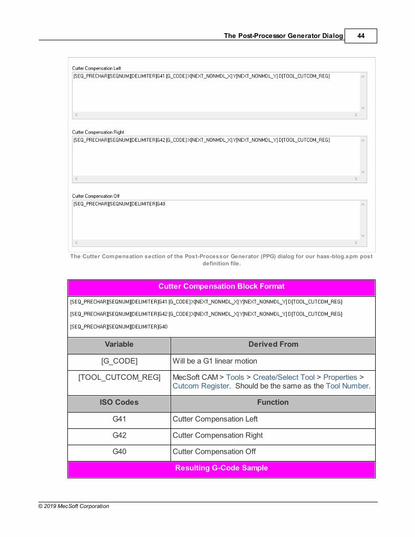
The Cutter Compensation section of the Post-Processor Generator (PPG) dialog for our haas-blog.spm post
definition file.
Cutter Compensation Block Format
Variable Derived From
[G_CODE] Will be a G1 linear motion
[TOOL_CUTCOM_REG] MecSoft CAM > Tools > Create/Select Tool > Properties >Cutcom Register. Should be the same as the Tool Number.
ISO Codes Function
G41 Cutter Compensation Left
G42 Cutter Compensation Right
G40 Cutter Compensation Off
Resulting G-Code Sample

2019 Post Processor (PPG) Decoded45
© 2019 MecSoft Corporation
6.12 PPG > Cut Motion Start/End
The Cut Motion Start/End section of the PPG is used for inserting additional code at the startor the end of every cut motion. For example, in the Motion section you can check the box toOutput cut motion start macro before plunge motion. If you add codes to the Start Up Codesection below, this option will include it prior to a Z plunge motion.
The Cut Motion Start/End section of the Post-Processor Generator (PPG) dialog for our haas-blog.spm post
definition file.

The Post-Processor Generator Dialog 46
© 2019 MecSoft Corporation
6.13 PPG > Cycles
The Cycles section of the PPG is used for all canned cycles. These are cycles that yourCNC controller is programmed to understand. For example all Drill, Tap and Bore Mops areposted out as canned cycles. Other cycles include User Defined Cycles, Turn ThreadCycles and Machine Control Cycles.
This is the color code for the Cycles section.
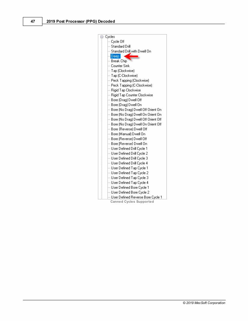
All of these are defined in this Cycles section of the PPG. We have shown the Deep Drillcycle dialog below since our part example has a Drill operation that is set to Deep Drill.
On the left of the PPG dialog you would expand the Cycles selection to see all of thesupported canned cycles. We are using the Deep cycle (G83).
2019 Post Processor (PPG) Decoded47
© 2019 MecSoft Corporation
Canned Cycles Supported
The Post-Processor Generator Dialog 48
© 2019 MecSoft Corporation
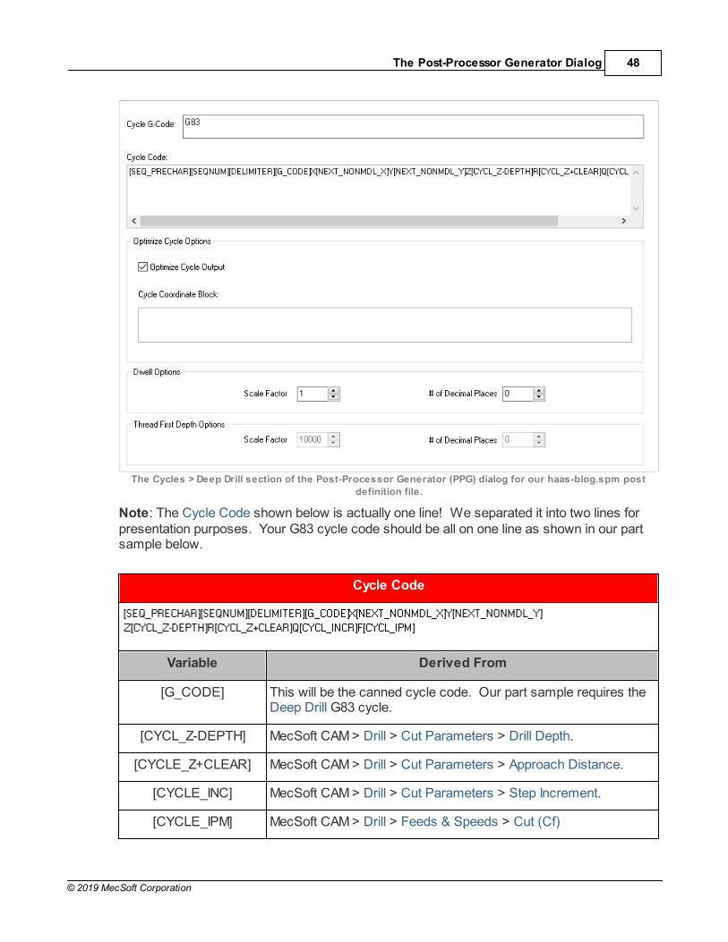
The Cycles > Deep Drill section of the Post-Processor Generator (PPG) dialog for our haas-blog.spm post
definition file.
Note: The Cycle Code shown below is actually one line! We separated it into two lines forpresentation purposes. Your G83 cycle code should be all on one line as shown in our partsample below.
Cycle Code
Variable Derived From
[G_CODE] This will be the canned cycle code. Our part sample requires theDeep Drill G83 cycle.
[CYCL_Z-DEPTH] MecSoft CAM > Drill > Cut Parameters > Drill Depth.
[CYCLE_Z+CLEAR] MecSoft CAM > Drill > Cut Parameters > Approach Distance.
[CYCLE_INC] MecSoft CAM > Drill > Cut Parameters > Step Increment.
[CYCLE_IPM] MecSoft CAM > Drill > Feeds & Speeds > Cut (Cf)

2019 Post Processor (PPG) Decoded49
© 2019 MecSoft Corporation
ISO Codes Function
G83 Deep Drill Cycle
R Position of the R (retract) plane
Q Depth of cut for each cutting feed (depth of each peck)
Resulting G-Code Sample
Notes:
1. Line N065 is the first deep drill cycle (G83). On this line Z is the Drill Depth of thehole, R is the Z location of the Approach Distance value and Q is the Step Incrementvalue.
2. Lines N066, N067 and N068 are the three remaining holes in the set. WithOptimized Cycle Output checked, only the change in X and Y are posted.
3. Line N069 cancels the canned cycle (G80).
6.14 PPG > Misc
The Misc section of the PPG is primarily used for Coolant Codes but also contains the WorkOffset Code.
This is the color code for the Misc section.

The Post-Processor Generator Dialog 50
© 2019 MecSoft Corporation
The Misc section of the Post-Processor Generator (PPG) dialog for our haas-blog.spm post definition file.
Resulting G-Code Sample
Notes:
1. To enable Coolant codes, make sure Coolant is set on the Feeds & Speeds tab ofthe Mop (MecSoft CAM > Holes > Drill > Feeds & Speeds > Coolant).
2. Even if you have Coolant set for the Tool (MecSoft CAM > Create/Select Tool >Properties > Coolant), it could be overwritten in the Feeds & Speeds tab of the Mopso see note #1 also.
2019 Post Processor (PPG) Decoded51
© 2019 MecSoft Corporation
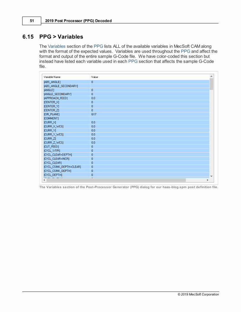
6.15 PPG > Variables
The Variables section of the PPG lists ALL of the available variables in MecSoft CAM alongwith the format of the expected values. Variables are used throughout the PPG and affect theformat and output of the entire sample G-Code file. We have color-coded this section butinstead have listed each variable used in each PPG section that affects the sample G-Codefile.
The Variables section of the Post-Processor Generator (PPG) dialog for our haas-blog.spm post definition file.

Index 52
© 2019 MecSoft Corporation
Index- 2 -2 Axis Hole Profiling 8
Cut Parameters 17
Posted G-Code 17
2 Axis Profiling 8
Cut Parameters 14
Posted G-Code 14
- A -About this Guide 3
Arc/Circle
Sample G-Code 35
Similar to Helix 35
Variables 35
- C -Cutter Compension
Sample G-Code 41
Variables 41
What to do first 41
What to Know 41
Cycles
Sample Deep Drill Cycle 46
- D -Drilling 8
Cut Parameters 19
Posted G-Code 19
- F -Feed Rate 30
Sample G-Code Control 32
- G -General
G-Code Control 22, 29, 30
- H -Helical 41
Helical Motions
Sample G-Code 38
Understanding 38
- M -Macros 7
Motion
Example G-Code 34
Multi Axis Motion 40
- P -Post-Processor 5
Post-Processor Generator 6
Circle 35
Cut Motion Start/End 45
Cutter Compensation 41
Cycles 46
Feed Rate 32
General 22
Helical/Spiral 38
Misc 49
Motion 34
Multi Axis Motion 40
Sample G-Code 22, 23, 26, 30, 32, 34, 35, 38,41, 46, 49
Setup 29
Spindle 30
Start/End 23
Tool Change 26
Variables 51
Post-Processor Generator Dialog 22
Print Tool List 26
- S -Sample G-Code
2 Axis Hole Profiling 17
2 Axis Profiling 14
Arc/Circles 35
Cutter Compensation 41
Drill Cycles 46
2019 Post Processor (PPG) Decoded53
© 2019 MecSoft Corporation
Sample G-Code
Drilling 19
File 10
Flood/Mist 49
Helical 38
Tool Change 26
Sample Toolpath 8
Set Post 8
Setup 8
Spindle
Example G-Code 30
Start/End G-Code Control 23
- T -Tool Change
Example G-Code 26
First Tool Load Macro 26
Print Tool List 26
Tool Change Macro 26
Variables Used 26
- V -Variables 7