positive and negative birefringence in packed films of
TRANSCRIPT

RSC Advances
PAPER
Ope
n A
cces
s A
rtic
le. P
ublis
hed
on 1
4 Ja
nuar
y 20
20. D
ownl
oade
d on
2/1
2/20
22 1
:07:
52 A
M.
Thi
s ar
ticle
is li
cens
ed u
nder
a C
reat
ive
Com
mon
s A
ttrib
utio
n-N
onC
omm
erci
al 3
.0 U
npor
ted
Lic
ence
.
View Article OnlineView Journal | View Issue
Positive and neg
aGraduate School of Bio-Applications and S
Agriculture and Technology, 2-24-16 Naka
E-mail: [email protected]; Fax: +81-42bDepartment of Chemical Engineering, Tokyo
2-24-16 Nakacho, Koganei, Tokyo 184-8588
† Electronic supplementary informa10.1039/c9ra09704j
Cite this: RSC Adv., 2020, 10, 2566
Received 20th November 2019Accepted 6th January 2020
DOI: 10.1039/c9ra09704j
rsc.li/rsc-advances
2566 | RSC Adv., 2020, 10, 2566–25
ative birefringence in packed filmsof binary spherical colloidal particles†
Kai Inoue a and Susumu Inasawa *ab
We have investigated the birefringence in packed films of binary spherical colloidal particles. Particulate
films were obtained by drying a mixed suspension of colloidal particles with two different diameters. We
observed positive and negative birefringence depending on the diameters and volume ratios of the large
and small particles. When the diameters of the large and small particles were similar, the films showed
positive birefringence. However, negative birefringence or weakening of positive birefringence was
observed in films with a large diameter ratio and an optimal volume fraction of large particles. The large
particles were embedded in packed small particles in the negative and weakened positive birefringent
films. We propose a packing structure in which a single shell layer of small particles formed around
a large particle. Using this model, we estimated the required volume ratio of large particles, and it was in
good agreement with the optimal volume fraction. The relation between the packing structure of the
binary colloidal particles and the birefringence is discussed.
1. Introduction
Deposition of particulate lms by drying colloidal suspensionshas been widely investigated because of its variety of applica-tions and manufacturing techniques in industry, such as forpaints,1 optical lms,2–4 electrodes,5,6 inkjet printing,7 and thedip-coating process.8 Mixing different sized particles isfrequently used to prepare slurries. Therefore, drying colloidalsuspensions with a binary size distribution has attracted muchattention for a decade.9 One of the most attractive issues is thesegregation or stratication phenomenon of small or largeparticles that occurs during drying.10–13 Sun et al.14 investigateddrying of a sessile droplet of a binary suspension. They foundthat segregation was enhanced as the wettability of thesubstrate increased, which was explained by the interplay of theevaporative ow and particle–substrate interaction near thecontact line. Patil et al.15 reported that self-sorting of binarycolloidal particles was observed around the contact line ofa drying sessile droplet. The patterns in the deposited particlessignicantly depended on the substrate temperature andparticle-diameter ratio. Formation of three types of depositionswas demonstrated: an inner deposition of mixed particles andring-like depositions with and without self-sorting. Further-more, not only stratication, but also ngering patterns
ystems Engineering, Tokyo University of
cho, Koganei, Tokyo 184-8588, Japan.
-388-7798; Tel: +81-42-388-7105
University of Agriculture and Technology,
, Japan
tion (ESI) available. See DOI:
74
induced by inward Marangoni ow that was more dominantthan the outward coffee ring effect have been observed.16 Otherresearch groups have also extensively investigated segregationof binary colloidal particles during drying, both experimentallyand numerically.17–19 These fundamental studies contribute todevelopment of a novel method with which a patterned depo-sition of binary colloidal particles can be obtained by simpledrying of binary colloidal suspensions.
The optical properties of particulate lms of binary colloidalparticles are interesting because of their tunable color andnonfading properties.20,21 For example, Foster et al.22 reportedstructural coloration using binary colloidal suspensions andcarbon black. Films produced by drop casting of suspensionsshowed different structural colors (white, blue, or green) bychanging the weight ratio of carbon black. Such structuralcolors were produced by suppression of wavelength-independent scattering. Kawamura et al.23,24 reported tuningof the structural color by changing the mixing ratio of two core–shell particles. In addition, a monolayer of binary crystals ofpolystyrene particles prepared by ethanol-assisted self-assemblyalso showed opal-like structural colors.25 These reports revealthat the appearance of particulate lms is affected by thediameters and mixing ratio of the binary particles.
While much attention has been paid to exhibition of thestructural color using binary colloidal particles, we believe thatthe optical anisotropy of packed lms is also important. It iswell known that birefringence emerges in lms of anisotropicmaterials, such as nanorods and nanotubes.26,27 Directionallyaligned rods or nanotubes cause optical anisotropy. Therefractive index parallel to the alignment differs from that inother directions, such as vertical to the alignment. For such
This journal is © The Royal Society of Chemistry 2020

Paper RSC Advances
Ope
n A
cces
s A
rtic
le. P
ublis
hed
on 1
4 Ja
nuar
y 20
20. D
ownl
oade
d on
2/1
2/20
22 1
:07:
52 A
M.
Thi
s ar
ticle
is li
cens
ed u
nder
a C
reat
ive
Com
mon
s A
ttrib
utio
n-N
onC
omm
erci
al 3
.0 U
npor
ted
Lic
ence
.View Article Online
aligned anisotropic particles, a theoretical model can be appliedto explain birefringence.28 This optical anisotropy is not causedby only the morphology of the material. Even particulate lmsof “spherical” particles show birefringence.1,29–31 Nanometer-scale anisotropy in the packing structure, in which packedparticles are directionally compressed by drying-inducedpacking, has been proposed to explain this phenomenon. Inbirefringence, a well-ordered packing structure of particles isnot necessary,30 which differs from the structural color. Bire-fringence of a binary-particulate lm has been briey reportedin a previous study.30 However, there is still a lack of funda-mental understanding about how the sizes and mixing ratio ofthe binary particles affect the optical anisotropy of the lms. Inthis study, we systematically investigated the sizes and mixingratio of binary colloidal particles. We revealed that positive andnegative birefringence occurs depending on the ratio. Theeffects of the particle sizes andmixing ratio on the birefringenceare discussed.
2. Experimental2.1 Preparation of binary suspensions
We used commercial colloidal silica suspensions in water. Fivecolloidal suspensions, Snowtex-XS, Snowtex-30, Snowtex-30L,MP-1040, and MP-2040, were purchased from Nissan Chem-ical Industries Inc. (Tokyo, Japan). We also used anothercolloidal silica suspension, Ludox TM-40, Sigma-Aldrich Co.,LLC (St. Louis, US). The fundamental information about thesuspensions, including the weight fraction of particles tosuspensions, diameter, and solution pH, is summarized inTable 1. The data was provided by the suppliers. We alsomeasured the zeta potentials of the suspended particles bydynamic light scattering (DLS, Zetasizer Nano-ZS, MalvernPanalytical Ltd., Malvern, UK). All of the colloidal particles werenegatively charged and we consider that they were initially welldispersed. Binary suspensions were prepared by mixing two ofthe suspensions. The diameters andmixing volume ratios of thebinary suspensions are summarized in Table 2. Aer we mixedtwo suspensions by hand, they were further mixed in an ultra-sonic bath for several minutes. We dene the ratio of the largerdiameter particles (dL) to the smaller diameter particles (dS) asa ¼ dL/dS. As shown in Table 2, we changed a and the volumefraction of large particles (4L) in sample preparation. Wedened 4L as the volume fraction of large particles to the totalvolume of dried binary particles. In all of the binary
Table 1 Characteristics of the colloidal silica suspensions used in the ex
SampleWeight fraction ofsuspended particles [%]
Snowtex-XS 20.4Snowtex-30 30.3Ludox-TM40 40.0Snowtex-30L 29.4MP-1040 40.0MP-2040 40.5
This journal is © The Royal Society of Chemistry 2020
suspensions, the initial weight fraction of mixed solid particleswas set to 20 wt% to the total weight of suspensions so that wewere able to observe a whole dried particulate lm clearly. Weconrmed that the initial weight fraction of binary particles didnot affect signs of the birefringence.
2.2 Film formation and observation of the particulate lms
A 2 ml aliquot of the suspension was cast onto a glass plate (NEOmicroscope cover glass, Matsunami Glass, Osaka, Japan). Thesuspensions were mainly dried at room temperature (approx. 25�C). The particulate lms obtained by droplet drying wereobserved by optical microscopy (Eclipse Ti2-E and AZ100,Nikon, Tokyo, Japan). We observed the lms in transmissionmode. For birefringent observation, the particulate lm wasinserted between two polarization plates (SPF-50C-32, SigmaKoki, Tokyo, Japan), which were set for crossed polarization. Wealso inserted a compensator (HI-RETAX-1l, Luceo, Tokyo,Japan) to visualize the birefringent color. The slow axis of thecompensator was oriented 45� to the polarization directions.Birefringent observation of the packed lms of mono-modalcolloidal particles is summarized in Fig. S1 in the ESI.† Thesurfaces of the particulate lms were observed by eld-emissionscanning electron microscopy (FE-SEM, JSM-6330FS, JEOL,Tokyo, Japan). Thickness of formed lms was measured bya confocal laser displacement meter (LT9500, Keyence Co.,Tokyo, Japan). As seen in Fig. 1, there was a variation in lmthickness of formed samples but the maximum lm thicknessin each sample was typically 110 � 10 mm. We note that varia-tion in lm thickness did not affect signs of birefringence inparticulate lms.
3. Results and discussion3.1 Positive and negative birefringence
Photographs of a particulate lm made of binary particles (a ¼2.2) with 4L¼ 0.7 are shown in Fig. 1a–c. The pale yellow packedlm in the transmission image in Fig. 1a shows the maltasepattern under crossed-nicols observation (Fig. 1b). This patternmeans that the packed lm had the birefringent property. Thedifference in the refractive indices of the packed lm wasvisualized by insertion of a compensator in crossed-nicolsobservation (Fig. 1c). The color pattern in which the rst andthird quadrants are blue and the second and forth quadrantsare orange-red means that the refractive index of the packed
periments
Diameter (d)[nm]
Zeta potential[mV] pH
5 �39 9.212 �30 10.020 �37 9.045 �38 11.0
100 �45 9.4200 �40 9.5
RSC Adv., 2020, 10, 2566–2574 | 2567
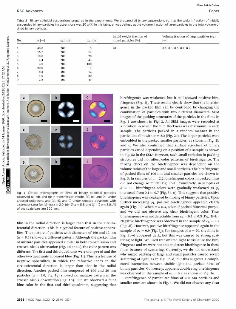
Table 2 Binary colloidal suspensions prepared in the experiments. We prepared all binary suspensions so that the weight fraction of initiallysuspended binary particles in suspensions was 20 wt%. In this table, 4L was defined as the volume fraction of large particles to the total volume ofdried binary particles
No. a [—] dL [nm] dS [nm]Initial weight fraction ofmixed particles [%]
Volume fraction of large particles (4L)[—]
1 40.0 200 5 20 0.1, 0.3, 0.5, 0.7, 0.92 16.7 200 123 10.0 200 204 4.4 200 455 2.0 200 1006 20.0 100 57 8.3 100 128 5.0 100 209 2.2 100 45
Fig. 1 Optical micrographs of films of binary colloidal particlesobserved (a), (d), and (g) in transmission mode, (b), (e), and (h) undercrossed polarizers, and (c), (f), and (i) under crossed polarizers witha compensator for (a)–(c) a¼ 2.0, (d)–(f) a¼ 8.3, and (g)–(i) a¼ 5.0. Allof the scale bars are 500 mm.
RSC Advances Paper
Ope
n A
cces
s A
rtic
le. P
ublis
hed
on 1
4 Ja
nuar
y 20
20. D
ownl
oade
d on
2/1
2/20
22 1
:07:
52 A
M.
Thi
s ar
ticle
is li
cens
ed u
nder
a C
reat
ive
Com
mon
s A
ttrib
utio
n-N
onC
omm
erci
al 3
.0 U
npor
ted
Lic
ence
.View Article Online
lm in the radial direction is larger than that in the circum-ferential direction. This is a typical feature of positive spheru-lites. The mixture of particles with diameters of 100 and 12 nm(a ¼ 8.3) showed a different pattern. Although the packed lmof mixture particles appeared similar in both transmission andcrossed-nicols observation (Fig. 1d and e), the color pattern wasdifferent. The rst and third quadrants were orange-red and theother two quadrants appeared blue (Fig. 1f). This is a feature ofnegative spherulites, in which the refractive index in thecircumferential direction is larger than that in the radialdirection. Another packed lm composed of 100 and 20 nmparticles (a ¼ 5.0, Fig. 1g) showed no maltase pattern in thecrossed-nicols observation (Fig. 1h). But, we observed a faintblue color in the rst and third quadrants, suggesting that
2568 | RSC Adv., 2020, 10, 2566–2574
birefringence was weakened but it still showed positive bire-fringence (Fig. 1i). These results clearly show that the birefrin-gence in the packed lm can be controlled by changing thecombination of particles with two different diameters. SEMimages of the packing structures of the particles in the lms inFig. 1 are shown in Fig. 2. All SEM images were recorded ata position in which the lm thickness was maximum in eachsample. The particles packed in a random manner in theparticulate lm with a ¼ 2.2 (Fig. 2a). The larger particles wereembedded in the packed smaller particles, as shown in Fig. 2band c. We also conrmed that surface structure of binaryparticles varied depending on a position of a sample as shownin Fig. S2 in the ESI.† However, such small variation in packingstructures did not affect color patterns of birefringence. Themixing effect on the birefringence was dependent on thevolume ratios of the large and small particles. The birefringenceof packed lms of 100 nm and smaller particles are shown inFig. 3. In samples of a ¼ 2.2, birefringent colors in packed lmsdid not change so much (Fig. 3p–t). Conversely, in samples ofa ¼ 5.0, birefringent colors were gradually weakened as 4L
increased from 0.1 to 0.7 (Fig. 3k–n). This suggests that positivebirefringence was weakened by mixing of binary particles. Uponfurther increasing 4L, positive birefringence appeared clearlyagain (Fig. 3o). When a ¼ 8.3, color of packed lms was purple,and we did not observe any clear birefringent color. Thusbirefringence was not detectable from 4L¼ 0.1 to 0.5 (Fig. 3f–h).Negative birefringence was observed in the sample of 4L ¼ 0.7(Fig. 3i). However, positive birefringence appeared again in thesample of 4L ¼ 0.9 (Fig. 3j). For samples of a ¼ 20, the lms inFig. 3b–d appeared dark, but this was caused by strong scat-tering of light. We used transmitted light to visualize the bire-fringence and we were not able to detect birefringence in theselms because of scattering. Currently, we do not understandwhy mixed packing of large and small particles caused severescattering of light, as in Fig. 3b–d, but this suggests a compli-cated interaction between visible light and packed lms ofbinary particles. Conversely, apparent double ring birefringencewas observed in the sample of 4L ¼ 0.9 as shown in Fig. 3e.
Birefringence of particulate lms of 200 nm particles andsmaller ones are shown in Fig. 4. We did not observe any clear
This journal is © The Royal Society of Chemistry 2020

Fig. 2 SEM images of the films in (a) Fig. 1a, (b) Fig. 1d, and (c) Fig. 1g. The scale bars are 500 nm.
Paper RSC Advances
Ope
n A
cces
s A
rtic
le. P
ublis
hed
on 1
4 Ja
nuar
y 20
20. D
ownl
oade
d on
2/1
2/20
22 1
:07:
52 A
M.
Thi
s ar
ticle
is li
cens
ed u
nder
a C
reat
ive
Com
mon
s A
ttrib
utio
n-N
onC
omm
erci
al 3
.0 U
npor
ted
Lic
ence
.View Article Online
change in birefringence in the samples of a¼ 2.0. Weakening ofpositive birefringence was observed in the samples of a ¼ 4.4when 4L increased from 0.1 to 0.7 as shown in Fig. 4p–s. Uponfurther increasing 4L, clear color pattern of positive birefrin-gence appeared again (Fig. 4t). Both weakening of positivebirefringence and emergence of negative birefringence wereobserved in the samples of a ¼ 10 (Fig. 4k–o). For further
Fig. 3 Optical micrographs of packed films of 100 nm and smaller particl(f)–(j) a ¼ 8.3, (k)–(o) a ¼ 5.0, and (p)–(t) a ¼ 2.2. Frame colors of imagimages, stand for types of birefringence of samples: positive (red), negainsets in (b)–(d) show transmission optical microscope images of the samwe clearly observed positive birefringence in the inner ring. However, wouter ring. Therefore, it was categorized “positive”. All of the scale bars a
This journal is © The Royal Society of Chemistry 2020
increasing a, we prepared 10 samples as shown in Fig. 4a–j, butwe were able to detect birefringence only in three samples(Fig. 4e, i and j). All three samples showed negative birefrin-gence, including double-ring samples in Fig. 4e and j. SEMimages of the lms with 4L of 0.7 and a ¼ 2.0, 4.4 and 10 areshown in Fig. 5. Similar to the images in Fig. 2, the large
es under birefringent observation. We changed 4L and a. (a)–(e) a¼ 20,es, which correspond to the background colors for alphabet (a)–(t) intive (blue) and not detectable birefringence (purple), respectively. Thee films. We note that the sample in (j) showed double-ring structure ande did not observe any clear birefringent color except for purple in there 500 mm.
RSC Adv., 2020, 10, 2566–2574 | 2569

Fig. 4 Optical micrographs of packed films of 200 nm and smaller particles under birefringent observation. We changed the volume ratio oflarge particles 4L and the diameter ratio a. (a)–(e) a ¼ 40, (f)–(j) a ¼ 17, (k)–(o) a ¼ 10, (p)–(t) a¼ 4.4, and (u)–(y) a ¼ 2.0. Frame colors of images,which correspond to the background colors for alphabet (a)–(y) in images, stand for types of birefringence of samples: positive (red), negative(blue) and not detectable birefringence (purple), respectively. All of the scale bars are 500 mm. The insets in (b)–(d) show transmission opticalmicroscope images of the same films. The insets in (e) and (j) showed enlarged images of parts of the samples, indicated by dotted boxes in theimages. Both samples showed double ring birefringence. In the outer rings in (e) and (j), the first and third quadrants were brighter than in thesecond and forth quadrants, suggesting that the outer rings in these samples showed negative birefringence.
Fig. 5 SEM images of the films in (a) Fig. 4x, (b) Fig. 4s, and (c) Fig. 4n. The scale bars are 500 nm.
2570 | RSC Adv., 2020, 10, 2566–2574 This journal is © The Royal Society of Chemistry 2020
RSC Advances Paper
Ope
n A
cces
s A
rtic
le. P
ublis
hed
on 1
4 Ja
nuar
y 20
20. D
ownl
oade
d on
2/1
2/20
22 1
:07:
52 A
M.
Thi
s ar
ticle
is li
cens
ed u
nder
a C
reat
ive
Com
mon
s A
ttrib
utio
n-N
onC
omm
erci
al 3
.0 U
npor
ted
Lic
ence
.View Article Online

Paper RSC Advances
Ope
n A
cces
s A
rtic
le. P
ublis
hed
on 1
4 Ja
nuar
y 20
20. D
ownl
oade
d on
2/1
2/20
22 1
:07:
52 A
M.
Thi
s ar
ticle
is li
cens
ed u
nder
a C
reat
ive
Com
mon
s A
ttrib
utio
n-N
onC
omm
erci
al 3
.0 U
npor
ted
Lic
ence
.View Article Online
particles appeared to be embedded in the packed smallparticles.
The above lms were all obtained by drying a suspension inwhich two types of particles were completely mixed beforedrying. We changed the drying procedure as follows. We rstplaced a suspension of large particles (100 nm) on a substrate.Aer drying for a desired period of time, we added a suspensionof small particles (12 nm) to the drying suspension of largeparticles. When we added the suspension of small particlesaer drying the suspension for 30 s, negative birefringenceappeared in the dried lm (Fig. 6a). When we added thesuspension of small particles aer drying for 120 s, birefrin-gence appeared, but in a complicated manner (Fig. 6b). Wefurther investigated the mixture of particles in a different way.Aer the suspension of large particles completely dried, weplaced a suspension of small particles on the lm of largeparticles. The formed lm showed positive birefringence(Fig. 6c). The same result was obtained when we addeda suspension of large particles on a packed lm of smallparticles (Fig. 6d). Thus, simultaneous packing of both largeand small particles was necessary for changes in thebirefringence.
3.2 Mechanism of positive and negative birefringence inpacked lms
In this work, we found that packed lms of binary particlesshowed two types of birefringence: positive and negative
Fig. 6 Birefringence of packed films of 100 and 12 nm particles. Filmsformed by drying a suspension of 100 nm particles for (a) 30 s and (b)120 s and then adding a suspension of 12 nm particles. (c) Film formedby adding a suspension of 12 nm particles to a completely driedsuspension of 100 nm particles. (d) Film formed by adding a suspen-sion of 100 nm particles to a complete dried suspension of 12 nmparticles. The scale bar in (a) is 500 mm.
This journal is © The Royal Society of Chemistry 2020
birefringence (Fig. 1). Negative birefringence of a packed lm ofmixed binary particles was briey reported in ref. 30, but thedetailed mechanism was not investigated. In positive spheru-lites of packed particles with a mono-modal size distribution,the colloidal particles more tightly pack in the radial directionthan in the circumferential direction.30 Because of the smallerdistance between the packed particles in the radial direction,the refractive index is larger than that in the other direction.Spontaneous ow of the drying suspension from the center tothe edge of the cast droplet has been proposed to be the originof the directional compression of packed particles.30 Thepacked lms of mixed particles showed negative birefringence(Fig. 1f). According to the same interpretation, negative bire-fringence means a larger refractive index in the circumferentialdirection than in the radial direction. This suggests that theparticles were more tightly packed in the circumferentialdirection. We observed the suspension ow during drying andconrmed that there was no signicant difference in the owpatterns in drying of binary colloidal suspensions. Therefore,suspension ow was not the origin of the change in thebirefringence.
Another important issue is that there was an optimal volumeratio for the change in the birefringence. In these lms, largeparticles were embedded in between packed small particles.The volume ratio of large particles affected the packing struc-ture of particles, as shown in Fig. 7 in which we used binarycolloids of 100 and 20 nm particles. The distance between thelarge particles was longer when the volume ratio of largeparticles was smaller, as shown in Fig. 7a–c. The large particleswere embedded in packed small particles and isolated. In
Fig. 7 SEM images of packed films of 100 and 20 nm particles withdifferent volume ratios: (a) 4L ¼ 0.1, (b) 4L ¼ 0.3, (c) 4L ¼ 0.5, and (d) 4L
¼ 0.9. The film with 4L ¼ 0.7 is shown in Fig. 2c. All of the scale bars are500 nm.
RSC Adv., 2020, 10, 2566–2574 | 2571

Fig. 9 SEM images of the (a) outer and (b) inner rings of the packedfilm in Fig. 3e. The scale bars are 500 nm. The inset in (a) is a magnifiedimage of (a). The scale bar in the insert is 200 nm.
RSC Advances Paper
Ope
n A
cces
s A
rtic
le. P
ublis
hed
on 1
4 Ja
nuar
y 20
20. D
ownl
oade
d on
2/1
2/20
22 1
:07:
52 A
M.
Thi
s ar
ticle
is li
cens
ed u
nder
a C
reat
ive
Com
mon
s A
ttrib
utio
n-N
onC
omm
erci
al 3
.0 U
npor
ted
Lic
ence
.View Article Online
addition, a regular structure of small particles was observed.Thus, the large particles did not signicantly disturb packing ofsmall particles, and the birefringent property of the packed lmwas mainly determined by the small particles. In contrast, wedid not observe any effect of addition of small particles when 4L
¼ 0.9 for a ¼ 5.0, although the small particles were packedbetween the large particles (Fig. 7d). In this case, the largeparticles mainly affected the birefringent property of the lm,probably because of many direct contacts between large parti-cles. On the basis of these results, we propose that packing ofboth large and small particles needs to be disturbed to showa change in the birefringence. In other words, a large particledoes not directly contact other large particles, but the inter-particle distance between large particles should be small. Inaddition, the small particles should be packed between largeparticles. One possible packing structure is schematicallyillustrated in Fig. 8. This structure is strongly supported by thepacking structure of the lm that showed double ring bire-fringence (Fig. 3e). The inner positive birefringent part mainlyconsisted of packed large particles (Fig. 9b). In contrast, thesmall particles were packed between large particles and thedistance between large particles was very small in the outernegative birefringent lm (Fig. 9a). Therefore, such mixedpacking of large and small particles is necessary for negativebirefringence. The small particles were mainly observed in theouter ring. This is because small particles preferentiallyprecipitate at the rim of the drying interface.10,12,15 The volumeratio of small particles in Fig. 3e was 0.1 and almost all of thesmall particles were packed around the rim. Hence, the centerof the packed lm mainly consisted of large particles andpositive birefringence was observed.
A large particle packs along the ow from the center to theedge. This induces directional packing of the particle. In thebulk material, directional compression causes expansion of thematerial, where the direction is normal to the compressive
Fig. 8 Schematic illustrations of our model. (a) Three dimensional packinjust for clarity. In our mode, a single layer of small particles forms betweends. (b) A cross sectional image of packed binary particles on a plane indicaA single shell layer of small particles forms around a large particle.
2572 | RSC Adv., 2020, 10, 2566–2574
direction. The ratio of these distortions is dened as Poisson'sratio. Similar to this, the small particles pack between largeparticles, and radial compression would induce expansion ofthe packed layer of small particles to the circumferentialdirection, as shown in Fig. 10. This would result in a decrease inthe packing distance between particles in the circumferentialdirection, which causes negative birefringence in packed lmsof binary particles, as shown in Fig. 1. However such conversionin compressive direction would not be easy to occur in partic-ulate lms and this would be a reason why we observed negativebirefringence only in limited number of samples. The diameterratio also affects the change in the birefringence. Becausepacking conditions gradually changed as the diameter ratioincreases, negative birefringence or weakening of positivebirefringence appeared as in Fig. 3 and 4. Further study on thispoint could provide a new insight in mechanical responses inpacked-binary particulate lms. Such study would be helpful toestablish a theory to describe birefringence in packed sphericalparticles.
g of large particles. We note that only large particles are sketched in (a)large particles, and the surface distance between each large particle is
ted by the dotted red rectangular in the three-dimensional sketch in (a).
This journal is © The Royal Society of Chemistry 2020

Fig. 10 Schematic illustration of formation of a film that shows negative birefringence.
Paper RSC Advances
Ope
n A
cces
s A
rtic
le. P
ublis
hed
on 1
4 Ja
nuar
y 20
20. D
ownl
oade
d on
2/1
2/20
22 1
:07:
52 A
M.
Thi
s ar
ticle
is li
cens
ed u
nder
a C
reat
ive
Com
mon
s A
ttrib
utio
n-N
onC
omm
erci
al 3
.0 U
npor
ted
Lic
ence
.View Article Online
3.3 Estimation of 4L based on the proposed structure
We estimated the volume ratio required to form the structureshown in Fig. 8. Assuming that a single layer of small particlesforms between the large particles, the volume of the shell of thesmall particles is approximately described by pdL
2dS/2. Thevolume of a large particle is pdL
3/6. Thus, the relation betweenthe volumes and volume fractions is
1
6pdL
3 :
�1
2pdL
2dS þ 1
6pdL
3
�¼ 4L : ð4L þ 4SÞ; (1)
where 4S is the dry-state volume fraction of the small particlesin packed lms. From eqn (1), 4S ¼ 3(dS/dL)4L. The sum of 4L
and 4S is 1. In addition, from our denition of the diameterratio, dS/dL ¼ a�1. Thus, we nally obtain the following relation:
4L ¼ a/(3 + a) (2)
From this relation, we obtained 4L z 0.77 for a ¼ 10 and 4L
z 0.63 for a ¼ 5. These are only approximations, but theysuggest that the volume fraction should be about 0.7 to form thepacked structure in Fig. 8. We consider that this is one of thereasons why negative and weakened positive birefringence mostclearly appeared at about 4L ¼ 0.7. In addition, we analyzedSEM image of the sample in Fig. 9a to estimate the actualvolume fraction of large particles in the outer ring. SEM imageprovides an area fraction of large particles but we need toconvert it to a volume fraction of large particles in packed binaryparticles. Assuming the radius of large particles as dL/2 andlarge particles packed in a square area of H2, then an areafraction of packed large particles on the surface of packed layer,fS, is estimated as fS ¼ p(dL/2)
2NS/H2, in which NS is the number
of large particles packed in the square. In a cubic box witha volume of H3, the number of packed particles in the box NV isroughly NV � (H/dL)NS. Therefore the total volume of largeparticles in the box, VLP, is VLP � (pdL
3/6)NV. We consider
This journal is © The Royal Society of Chemistry 2020
packing of binary spherical particles. The total volume fractionthat is occupied by spherical particles in the box is roughly 0.7.Therefore the volume fraction of large particles 4L is estimatedas VLP/(0.7H
3) � 20fS/21. The area fraction of large particles fS inthe outer ring obtained from Fig. 9a was 0.82 and this suggests4L � 0.8. Conversely, our model predicts 4L ¼ 0.87 for binaryparticles of a ¼ 20. This reasonable agreement also supportsour model. These results suggested that a packing structure inwhich large particles are packed but separated by a packed thinlayer of small particles would be necessary.
Drying of colloidal suspensions with a binary size distribu-tion has been extensively studied. One of the main points inthese studies is spontaneous segregation of the smaller parti-cles around the drying interface. However, our results revealedthat staggered packing of large and small particles is alsoa candidate to show a new property in the packed lm. Thus, weconsider that investigating the drying process in which mixedpacking of large and small particles spontaneously occurs isimportant to produce functional packed lms of binaryparticles.
4. Conclusions
We have demonstrated that positive and negative birefringenceemerged in lms of packed binary colloidal particles. Positivebirefringence was observed when a was small. In contrast,negative birefringence or weakening of positive birefringencewas clearly observed in lms with a large a and an optimalvolume fraction of large particles. We propose a staggeredpacking structure of large and small particles as the origin ofthe observed change in birefringence. The volume ratio of largeparticles required to form a single shell layer of small particlesaround a large particle was estimated to be about 0.7. Thisestimated value was in reasonable agreement with the experi-mental data. Our results suggest that precise control of the
RSC Adv., 2020, 10, 2566–2574 | 2573

RSC Advances Paper
Ope
n A
cces
s A
rtic
le. P
ublis
hed
on 1
4 Ja
nuar
y 20
20. D
ownl
oade
d on
2/1
2/20
22 1
:07:
52 A
M.
Thi
s ar
ticle
is li
cens
ed u
nder
a C
reat
ive
Com
mon
s A
ttrib
utio
n-N
onC
omm
erci
al 3
.0 U
npor
ted
Lic
ence
.View Article Online
packing structures of binary particles has the potential to formfunctional materials.
Conflicts of interest
There are no conict to declare.
Acknowledgements
This work was partially supported by JSPS KAKENHI (grantnumber: 16H02413). We thank Prof. H. Kamiya for hispermission to access the FE-SEM and DLS equipment. We thankTim Cooper, PhD, from Edanz Group (www.edanzediting.com/ac) for editing a dra of this manuscript.
References
1 L. Goehring, J. Li and P.-C. Kiatkirakajorn, Philos. Trans. R.Soc., A, 2016, 375, 20160161.
2 S. Portal-Marco, M.-A. Vallve, O. Arteaga, J. Ignes-Mullol,C. Corbella and E. Bertran, Colloids Surf., A, 2012, 401, 38–47.
3 J. H. Moon and S. Yang, Chem. Rev., 2010, 110(1), 547–574.4 E. Avci and M. Culha, RSC Adv., 2013, 3, 17829–17836.5 S. Lim, K. H. Ahn and M. Yamamura, Langmuir, 2013, 29(26),8233–8244.
6 S. Lim, S. Kim, K. H. Ahn and S. J. Lee, Ind. Eng. Chem. Res.,2015, 54(23), 6146–6155.
7 L. H. Mujawar, J. G. M. Kuerten, D. P. Siregar, A. vanAmerongen and W. Norde, RSC Adv., 2014, 4, 19380–19388.
8 C. Zhang and P. Akcora, RSC Adv., 2017, 7, 18321–18326.9 M. Schulz and J. L. Keddie, So Matter, 2018, 14, 6181–6197.10 E. Hendarto and Y. B. Gianchandani, J. Micromech.
Microeng., 2013, 23, 075016.11 D. K. Makepeace, A. Fortini, A. Markov, P. Locatelli,
C. Lindsay, S. Moorhouse, R. Lind, R. P. Sear andJ. L. Keddie, So Matter, 2017, 13, 6969–6980.
12 W. Liu, J. Midya, M. Kappl, H.-J. Butt and A. Nikoubashman,ACS Nano, 2019, 13(5), 4972–4979.
13 O. Cusola, S. Kivisto, S. Vierros, P. Batys, M. Ago, B. L. Tardy,L. G. Greca, M. B. Roncero, M. Sammalkorpi and O. J. Rojas,Langmuir, 2018, 34(20), 5759–5771.
2574 | RSC Adv., 2020, 10, 2566–2574
14 V. H. Chhasatia and Y. Sun, So Matter, 2011, 7, 10135–10143.
15 N. D. Patil, R. Bhardwaj and A. Sharma, Langmuir, 2018,34(40), 12058–12070.
16 B. M. Weon and J. H. Je, Phys. Rev. E: Stat., Nonlinear, SoMatter Phys., 2013, 87, 013003.
17 M. Parsa, S. Harmand and K. Seane, Adv. Colloid InterfaceSci., 2018, 254, 22–47.
18 F. Buss, C. C. Roberts, K. S. Crawford, K. Peters andL. F. Francis, J. Colloid Interface Sci., 2011, 359, 112–120.
19 N. R. Devlin, K. Loehr and M. T. Harris, AIChE J., 2015,61(10), 3547–3556.
20 K. Katagiri, Y. Tanaka, K. Uemura, K. Inumaru, T. Seki andY. Takeoka, NPG Asia Mater., 2017, 9, e355.
21 H. Fudouzi and Y. Xia, Langmuir, 2003, 19(23), 9653–9660.22 J. D. Forster, H. Noh, S. F. Liew, V. Saranathan, C. F. Schreck,
L. Yang, J.-G. Park, R. O. Prum, S. G. J. Mochrie, C. S. O'Hern,H. Cao and E. R. Dufresne, Adv. Mater., 2010, 22, 2939–3944.
23 A. Kawamura, M. Kohri, S. Yoshioka, T. Taniguchi andK. Kishikawa, Langmuir, 2017, 33(15), 3824–3830.
24 T. Iwasaki, Y. Tamai, M. Yamamoto, T. Taniguchi,K. Kishikawa and M. Kohri, Langmuir, 2018, 34(39), 11814–11821.
25 Z. Dai, Y. Li, G. Duan, L. Jia andW. Cai, ACS Nano, 2012, 6(8),6706–6716.
26 M. Mittal and E. M. Furst, Adv. Funct. Mater., 2009, 19, 3271–3278.
27 R. Duggal, F. Hussain and M. Pasquali, Adv. Mater., 2006, 18,29–34.
28 T. Scharf, Polarized light in liquid crystals and polymers, Wiley,2007.
29 S. Inasawa and Y. Yamaguchi, Langmuir, 2009, 25(18),11197–11201.
30 K. Yamaguchi, S. Inasawa and Y. Yamaguchi, Phys. Chem.Chem. Phys., 2013, 15, 2897–2902.
31 H. Miyazaki, K. Abe and S. Inasawa, Drying Technol., 2020,38(3), 385–394.
This journal is © The Royal Society of Chemistry 2020