pointmaster 200 6-channel multipoint recorder version · pdf filepointmaster 200 6-channel...
TRANSCRIPT
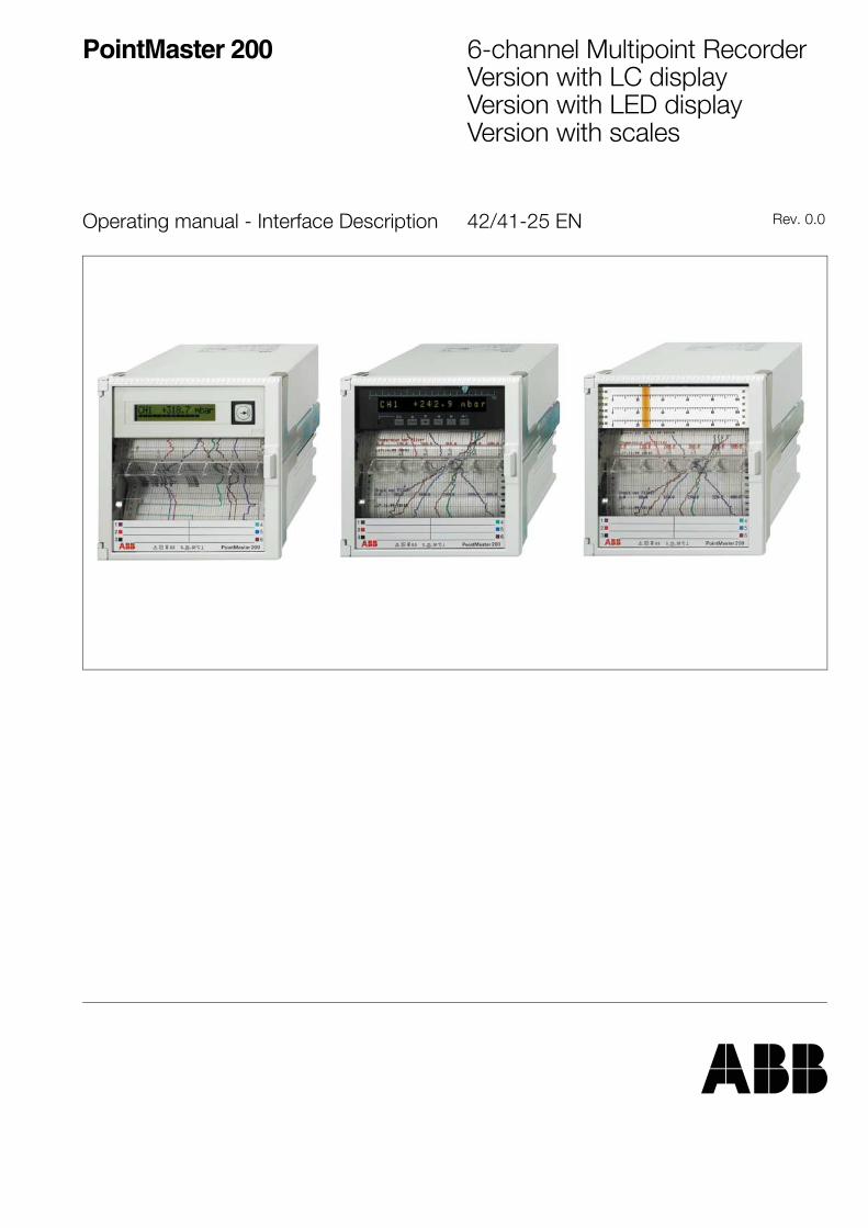
PointMaster 200 6-channel Multipoint RecorderVersion with LC displayVersion with LED displayVersion with scales
Operating manual - Interface Description 42/41-25 EN Rev. 0.0

Contents
Page
Description . . . . . . . . . . . . . . . . . . . . . . . . . . . . . . . 3
Technical dataof bus connection RS-485 . . . . . . . . . . . . . . . . . 3
Data formats . . . . . . . . . . . . . . . . . . . . . . . . . . . . . . 4
Data transmission
General . . . . . . . . . . . . . . . . . . . . . . . . . . . . . . . . . . . . . 6Telegram characters . . . . . . . . . . . . . . . . . . . . . . . . . . . . 6Permissible addresses . . . . . . . . . . . . . . . . . . . . . . . . . . 6Telegram formats, Framework specifications . . . . . . . . . . . 6
Telegram SD1 . . . . . . . . . . . . . . . . . . . . . . . . . . . . . 7Telegram SD2 . . . . . . . . . . . . . . . . . . . . . . . . . . . . . 7Telegram SD3 . . . . . . . . . . . . . . . . . . . . . . . . . . . . . 8
Transmission rules . . . . . . . . . . . . . . . . . . . . . . . . . . . . . 8
Parameter
Addressable parameters . . . . . . . . . . . . . . . . . . . . . . . . . 9Parameter field addresses . . . . . . . . . . . . . . . . . . . . . . . . 9Parameter - Addresses
System parameter 10H . . . . . . . . . . . . . . . . . . . . . . 10Channel parameters 11H to 16H . . . . . . . . . . . . . . . . 13Text lines 17H . . . . . . . . . . . . . . . . . . . . . . . . . . . . . 17Print intervals 18H . . . . . . . . . . . . . . . . . . . . . . . . . . 17Synchronisation times for text output 19H . . . . . . . . . 18Print colours 1AH . . . . . . . . . . . . . . . . . . . . . . . . . . . 18DI assignment 1BH . . . . . . . . . . . . . . . . . . . . . . . . . 19Date and time 1CH . . . . . . . . . . . . . . . . . . . . . . . . . 20Calibration data 1DH . . . . . . . . . . . . . . . . . . . . . . . . 20Channel measured values and instrument status 1EH 20Entering measured values into recorder 1FH . . . . . . . 22Reading accounting data 20H . . . . . . . . . . . . . . . . . . 23Writing equipment status 21H . . . . . . . . . . . . . . . . . . 24
Creation of text blocks . . . . . . . . . . . . . . . . . . . 25
Send printout lines to recorder . . . . . . . . . . . . . . . . . . . . . 25Scanning of printer status . . . . . . . . . . . . . . . . . . . . . . . . 26Sending a display line to the recorder F2H . . . . . . . . . . . 26Error register for communication FFH . . . . . . . . . . . . . . . . 27
WIZCON connection of the recorder . . . . . . 28
Interrogation of 8 values . . . . . . . . . . . . . . . . . . . . . . . . . 28Modification of 2 values . . . . . . . . . . . . . . . . . . . . . . . . . . 28Numerical formats . . . . . . . . . . . . . . . . . . . . . . . . . . . . . . 29Parameter addresses for function codes 04H and 07H . . . 29Interrogation of binary information . . . . . . . . . . . . . . . . . . 30Parameter addresses for function code 05H . . . . . . . . . . . 30
Character set table . . . . . . . . . . . . . . . . . . . . . . . . 31
Z-18967
2 Contents
1 DescriptionProvided for communication with the multi-point recorder is anRS 485 interface. The type of data protocol used is designed tosuit DIN 19 245 Part 1 (Profibus protocol). Only a part of thedirectives were taken into account. Among others, the directiveson the operation of a multimaster (Token-Passing-Procedures)were not taken into account, since the recorder is always apassive subscriber.
2 Technical data for bus connection RS 485
Bus structureLine without branchingsStub to subscriber < 0.3 m
Mediumshielded, twisted 2-wire linesurge resistance 100...130 Ω, for f > 100 kHzCable capacity < 60 pF/mCross section ≥ 0.22 mm2
Line length≤ 1200 m
Number of bus subscribers32 (active and passive)
Transmission speed600 / 1200 / 2400 / 4800 / 9600 / 19200 baud
Type of transmissionsymmetrical
Driver outputidle state ±5 V, with load ±1.5 Vload resistance 60 Ω
Receiversensitivity 200 mVinput resistance 12 kΩ
GroundingThe shield should be grounded on both ends to arrest highfrequency fault states
Potential balancingPotential variations between the data reference potentials(GND) of all bus subscribers may not exceed ±7 V
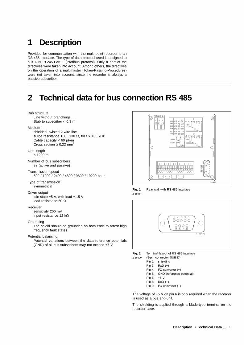
Fig. 1 Rear wall with RS 485 interfaceZ-18064
Fig. 2 Terminal layout of RS 485 interfaceZ-16529 (9-pin connector SUB D)
Pin 1 shieldingPin 3 RxD (+)Pin 4 I/O converter (+)Pin 5 GND (reference potential)Pin 6 +5 VPin 8 RxD (−)Pin 9 I/O converter (−)
The voltage of +5 V on pin 6 is only required when the recorderis used as a bus end-unit.
The shielding is applied through a blade-type terminal on therecorder case.
Description • Technical Data ... 3
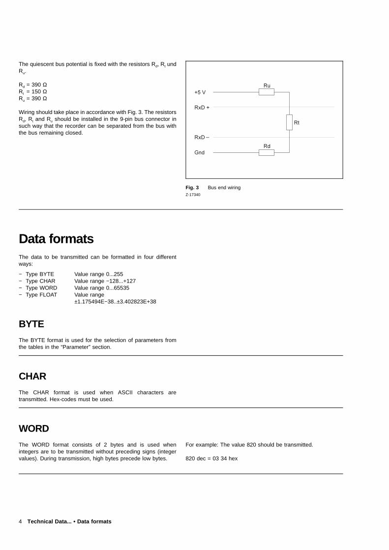
The quiescent bus potential is fixed with the resistors Rd, Rt undRu.
Rd = 390 ΩRt = 150 ΩRu = 390 Ω
Wiring should take place in accordance with Fig. 3. The resistorsRd, Rt and Ru should be installed in the 9-pin bus connector insuch way that the recorder can be separated from the bus withthe bus remaining closed.
Fig. 3 Bus end wiringZ-17340
Data formatsThe data to be transmitted can be formatted in four differentways:
− Type BYTE Value range 0...255− Type CHAR Value range −128...+127− Type WORD Value range 0...65535− Type FLOAT Value range
±1.175494E−38..±3.402823E+38
BYTE
The BYTE format is used for the selection of parameters fromthe tables in the “Parameter” section.
CHAR
The CHAR format is used when ASCII characters aretransmitted. Hex-codes must be used.
WORD
The WORD format consists of 2 bytes and is used whenintegers are to be transmitted without preceding signs (integervalues). During transmission, high bytes precede low bytes.
For example: The value 820 should be transmitted.
820 dec = 03 34 hex
4 Technical Data... • Data formats
FLOAT
The FLOAT format consists of 4 bytes and is used when floatingdecimal values are to be transmitted. The IEEE 754 formatshould be used. The numerical range accepted by the recorderlies within −9.990E9 and +9.990E9.
For example: transmit the value −12.5.
−12.5 dec = C1 48 00 00 hex
Determination of the hex figure
The general form of the floating decimal point is: (sign) × 2Exp−127
× (Rest).
The binary display of the figure −12.5 is
11000001 01001000 00000000 00000000
Exp Rest(8 bit) (23 bit)
negative sign
1. Calculate the sign:the bit is set in case of a negative sign.
2. Calculate the exponent:the highest exponent is calculated:
EXP = INT [lg”Figuredec”/lg2] + 127
in the example:INT [lg12.5/lg2] + 127 = 130 dec = 82 hex = 10000010 bi-nary
3. Calculate the rest:
Rest = “Figuredec”/2Exp
in the example:12.5/2130 − 127 = 1.562
4. Transform into binary code:
Rank : 20 + 2−1 + 2−2 + 2−3 + 2−4 + ... +2−23
In the example: 1 1 0 0 1
The value of 20 is always 1 and is therefore not carried for-ward.
Technical Data ... • Data formats 5
Data transmission
General
A combination of telegram characters is grouped together for thetransmission of data. The telegrams accept the “Handshakefunction”, i.e. each telegram from the computer to the recordermust be first confirmed before being sent.
NoticePrior to data transfer the interface address and the baud ratemust be defined.
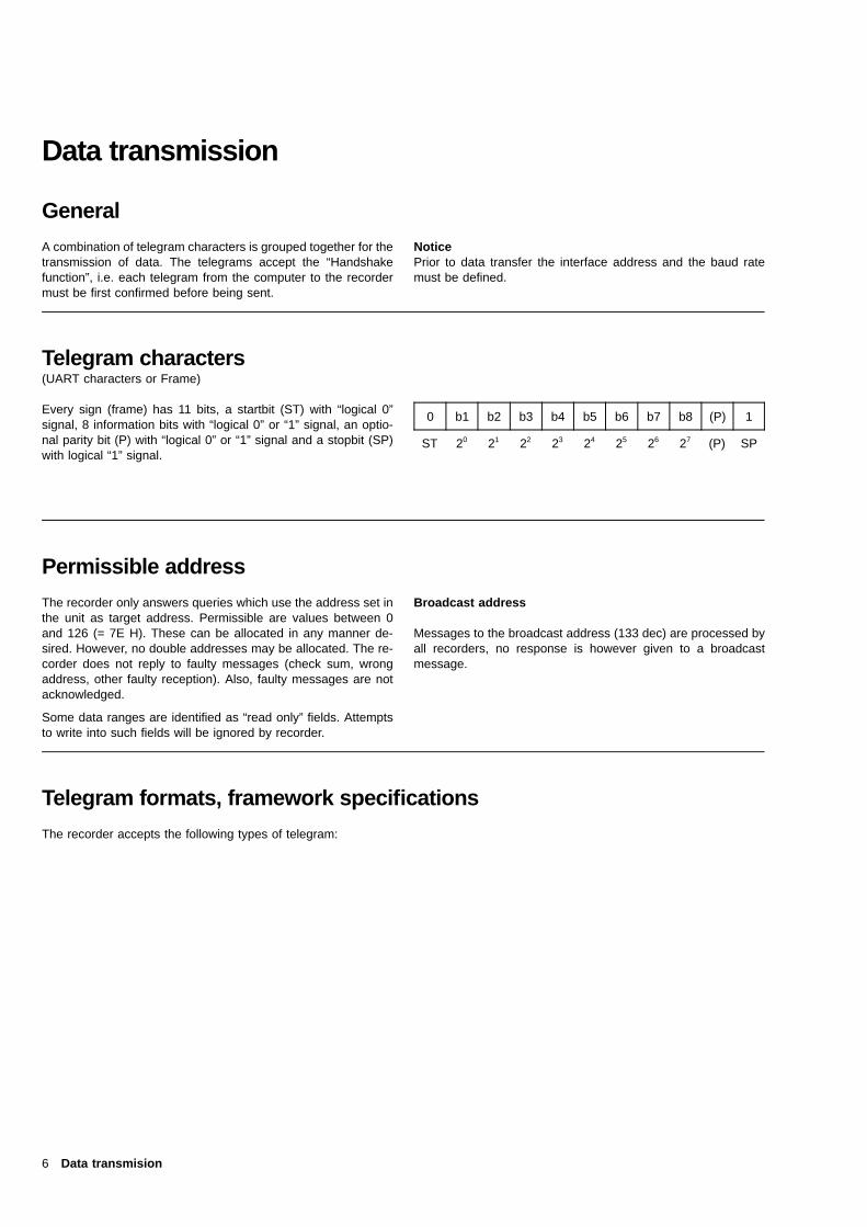
Telegram characters(UART characters or Frame)
Every sign (frame) has 11 bits, a startbit (ST) with “logical 0”signal, 8 information bits with “logical 0” or “1” signal, an optio-nal parity bit (P) with “logical 0” or “1” signal and a stopbit (SP)with logical “1” signal.
0 b1 b2 b3 b4 b5 b6 b7 b8 (P) 1
ST 20 21 22 23 24 25 26 27 (P) SP
Permissible address
The recorder only answers queries which use the address set inthe unit as target address. Permissible are values between 0and 126 (= 7E H). These can be allocated in any manner de-sired. However, no double addresses may be allocated. The re-corder does not reply to faulty messages (check sum, wrongaddress, other faulty reception). Also, faulty messages are notacknowledged.
Some data ranges are identified as “read only” fields. Attemptsto write into such fields will be ignored by recorder.
Broadcast address
Messages to the broadcast address (133 dec) are processed byall recorders, no response is however given to a broadcastmessage.
Telegram formats, framework specifications
The recorder accepts the following types of telegram:
6 Data transmision

Telegram SD1
Telegram with fixed information field length without data field
SD1/DA/SA/FC/FCS/ED|<-- L -->|
is used for sending a query to the recorder and for sendingacknowledgement by recorder.
Where:
SD1 = 10HStart byte (start delimiter), code: 10H
DA Target address (Destination Address)SA Source address (Source Address)FC Function code (Frame Control)FCS Test byte (Frame Check Sequence)
Sum of the hex value of the L frame without transfor-mation for FFH
ED End byte (End Delimiter), code: 16HL number of bytes in FCS = 3
In reply to a query with FC = 01H (ident-interrogation) the re-corder will also respond in the SD1 format. If the unit has noself-test function, the response is in FC = 10H, otherwise it is FC= 11H.
The ident recognition of the recorder is conducted with the func-tion code 4EH as follows:
In reply to a query with FC = 4EH the recorder replies with amessage in SD2 format.
The “Data field” of the recognition message is assigned asfollows:
LE_VN/LE_CT/LE_HR/LE_SR/VN/CT/HR/SR
LE_VN = 03HLE_CT = 11HLE_HR = 05HLE_SR = 05HVN = “xxx”
Manufacturer’s codeCT = “41422; xxx”
Catalog number and apparatusHR = “CPU:A”"
Index of the recorder CPU cardSR = “00.00.16”
Example for software release
Telegram SD2
Telegram with variable information field length
SD2/LE/LEr/SD2/DA/SA/FC/aa/oo/oo/cc/data field/FCS/ED|<-- L -->|
is used for sending data to the recorder and for sending repliesfrom the recorder.
Where:
SD2 = 68HStart byte
LE Number of data bytes + 7LEr Repetition of LESD2 = 68H
Repetition of start byteDA Target address (bus subscriber address)SA Source addressFC Function code:
16H = send data to the recorder15H = read data from recorder
aa Basic address of the parameter fieldoo oo 2 byte parameter address (= offset)cc Number of Datenbytesdatafield Data for transmissionFCS Test byte (Frame Check Sequence)
Sum of the hex value of the L frame without transfor-mation for FFH
ED = 16HEnd code
L Number of Bytes in FCS
Upon receiving a data message in SD2 format, the recorderresponds with a message in SD1 format.
The altered data is written into the non-volatile memory afterreceipt of the save command.
The function code 16H is used to send data to the recorder. Therecorder uses the function code 15H to send reply telegrams inSD2 format.
Data transmission 7
Telegram SD3
Telegram with fixed information length
SD3/DA/SA/FC/aa/oo/oo/cc/xx/xx/xx/xx/FCS/ED|<-- L -->|
is used for sending a query to the recorder.
Where:
SD3 = A2HStart byte
DA Target address (bus subscriber address)SA Source addressFC = 15H
Function codeaa Basic address of the parameter fieldoo oo 2 byte parameter address (offset)cc Number of data bytesxx xxxx xx 4 random bytesFCS Test byte (Frame Check Sequence)
Sum of the hex value of the L frame without transfor-mation for FFH
ED = 16HEnd byte (End Delimiter), code: 16H
L Number of Bytes in FCS
Transmission rules
The idle state of the line corresponds to the logical “1” signal.Before data transmission starts − from the PC − a minimum timeof 33 bits (syn-time) as idle state is required for synchronisation.
Pauses of the length ≥ 3 frames shall be interpreted as telegramend.
The recorder inserts a pause of ≤ 300 ms each between thereception of the last stop bit and the first start bit.
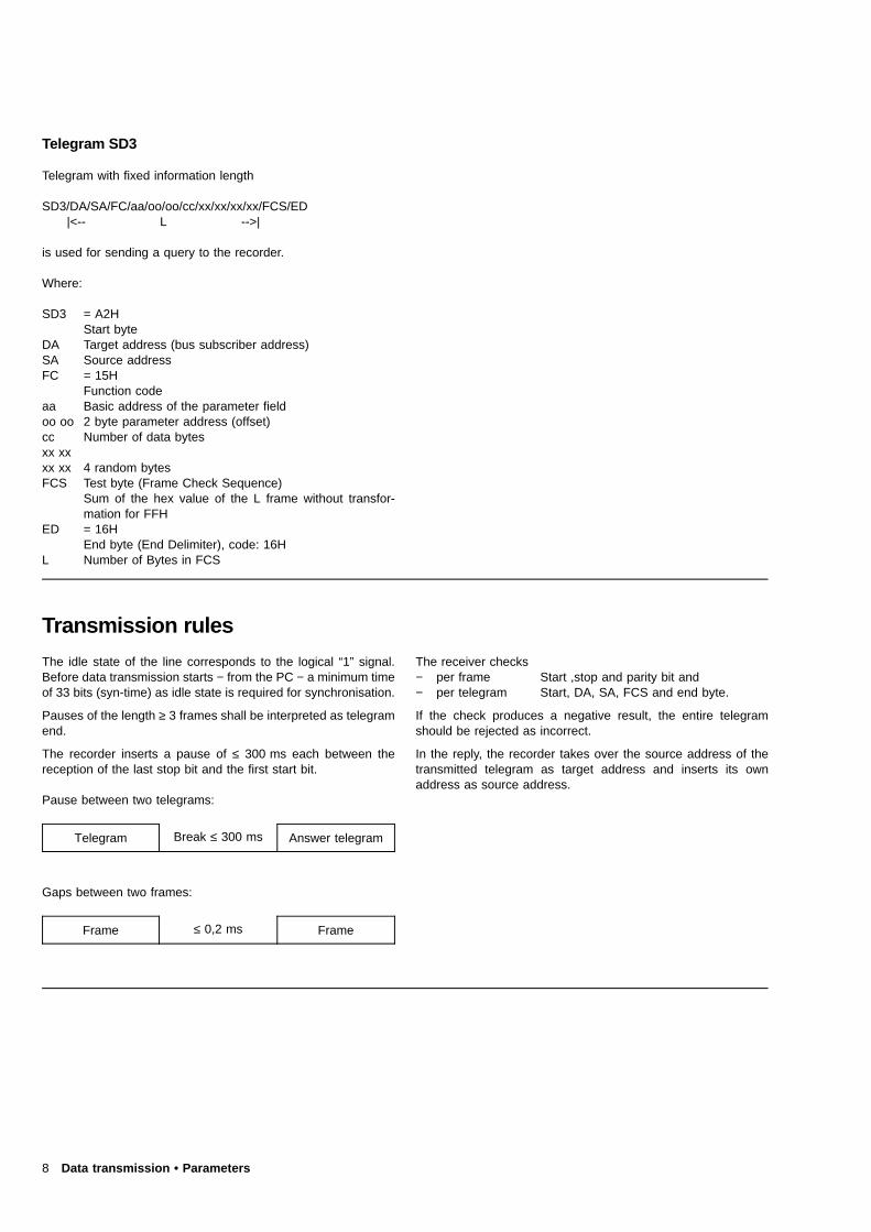
Pause between two telegrams:
Telegram Break ≤ 300 ms Answer telegram
Gaps between two frames:
Frame ≤ 0,2 ms Frame
The receiver checks− per frame Start ,stop and parity bit and− per telegram Start, DA, SA, FCS and end byte.
If the check produces a negative result, the entire telegramshould be rejected as incorrect.
In the reply, the recorder takes over the source address of thetransmitted telegram as target address and inserts its ownaddress as source address.
8 Data transmission • Parameters
Parameters
Addressable parameters
The following parameters can be read or modified with telegramsSD2 and SD3 (see corresponding sections on pages 7 and 8).To be able to do this, a parameter field address (see table onthe right), the parameter address (offset, page 10) and the codeof the parameter value are required.
For example
The following information is required for the first chart speed:
Parameter field address 10HParameter address (offset) 0000HCode for the chart speed 20 mm/h 04H
Parameter field address
Instrument function group Parameter fieldaddress
System parameterisation
Parameterisation, channel 1Parameterisation, channal 2Parameterisation, channel 3Parameterisation, channel 4Parameterisation, channel 5Parameterisation, channel 6
Text lines
Print intervalsPrint synchronisation timesPrint colours
DI assignment
Date and time
Calibration data
Measured values and equipment statusSending measured values to the recorderReading accounting data (block transfer)Writing the equipment status
Sending the print lineSending the display line to the recorder
Communication error register
10H
11H12H13H14H15H16H
17H
18H19H1AH
1BH
1CH
1DH
1EH1FH20H21H
F1HF2H
FFH
The above-named addresses are input into the appropriate fieldsof a message during communication. From the address, the re-corder determines the data range to be transmitted. The datatransmission takes place with messages in the SD2 and SD3formats. To read a data field, FC = 15H must always be used,FC = 16H must be used to write a data field. If invalid parametervalues are contained in a message, the negative acknowledge-ment (SD1, FC = 11H) is transmitted by the recorder in reply.
Parameters 9
Parameter addresses
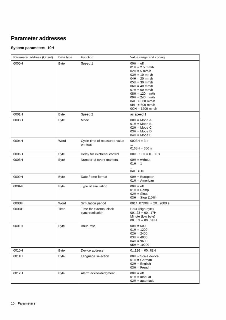
System parameters 10H
Parameter address (Offset) Data type Function Value range and coding
0000H Byte Speed 1 00H = off01H = 2.5 mm/h02H = 5 mm/h03H = 10 mm/h04H = 20 mm/h05H = 30 mm/h06H = 40 mm/h07H = 60 mm/h08H = 120 mm/h09H = 240 mm/h0AH = 300 mm/h0BH = 600 mm/h0CH = 1200 mm/h
0001H Byte Speed 2 as speed 1
0003H Byte Mode 00H = Mode A01H = Mode B02H = Mode C03H = Mode D04H = Mode E
0004H Word Cycle time of measured valueprintout
0003H = 3 s...0168H = 360 s
0006H Byte Delay for exctrenal control 00H...1EH = 0...30 s
0008H Byte Number of event markers 00H = without01H = 1..0AH = 10
0009H Byte Date / time format 00H = European01H = American
000AH Byte Type of simulation 00H = off01H = Ramp02H = Sinus03H = Step (10%)
000BH Word Simulation period 0014..07D0H = 20...2000 s
000DH Time Time for external clocksynchronisation
Hour (high byte)00...23 = 00...17HMinute (low byte)00...59 = 00...3BH
000FH Byte Baud rate 00H = 60001H = 120002H = 240003H = 480004H = 960005H = 19200
0010H Byte Device address 0...126 = 00..7EH
0011H Byte Language selection 00H = Scale device01H = German02H = English03H = French
0012H Byte Alarm acknowledgment 00H = off01H = manual02H = automatic
10 Parameters
Parameter address (Offset) Data type Function Value range and coding
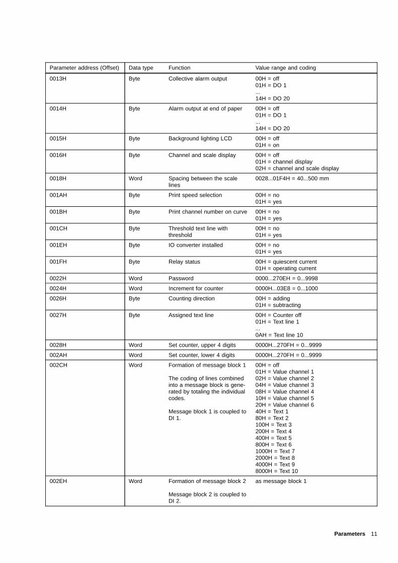
0013H Byte Collective alarm output 00H = off01H = DO 1...14H = DO 20
0014H Byte Alarm output at end of paper 00H = off01H = DO 1...14H = DO 20
0015H Byte Background lighting LCD 00H = off01H = on
0016H Byte Channel and scale display 00H = off01H = channel display02H = channel and scale display
0018H Word Spacing between the scalelines
0028...01F4H = 40...500 mm
001AH Byte Print speed selection 00H = no01H = yes
001BH Byte Print channel number on curve 00H = no01H = yes
001CH Byte Threshold text line withthreshold
00H = no01H = yes
001EH Byte IO converter installed 00H = no01H = yes
001FH Byte Relay status 00H = quiescent current01H = operating current
0022H Word Password 0000...270EH = 0...9998
0024H Word Increment for counter 0000H...03E8 = 0...1000
0026H Byte Counting direction 00H = adding01H = subtracting
0027H Byte Assigned text line 00H = Counter off01H = Text line 1...0AH = Text line 10
0028H Word Set counter, upper 4 digits 0000H...270FH = 0...9999
002AH Word Set counter, lower 4 digits 0000H...270FH = 0...9999
002CH Word Formation of message block 1
The coding of lines combinedinto a message block is gene-rated by totaling the individualcodes.
Message block 1 is coupled toDI 1.
00H = off01H = Value channel 102H = Value channel 204H = Value channel 308H = Value channel 410H = Value channel 520H = Value channel 640H = Text 180H = Text 2100H = Text 3200H = Text 4400H = Text 5800H = Text 61000H = Text 72000H = Text 84000H = Text 98000H = Text 10
002EH Word Formation of message block 2
Message block 2 is coupled toDI 2.
as message block 1
Parameters 11

Parameter address (Offset) Data type Function Value range and coding
0030H Word Formation of message block 3
Message block 3 is coupled toDI 3.
as message block 1
0032H Word Formation of message block 4
Message block 4 is coupled toDI 4.
as message block 1
0034H Byte Standby mode 00H = not active01H = on via DI, off via threshold02H = on via DI, off via key FT03H = on via Power on, off via threshold04H = on via Power on, off via key FT
0035H Byte Standby delay time 00H...C8H = 0...200 min
0036H Word Standby threshold coding 0000H = inactive0001H = channel 1, threshold 10002H = channel 1, threshold 20004H = channel 2, threshold 10008H = channel 2, threshold 20010H = channel 3, threshold 10020H = channel 3, threshold 20040H = channel 4, threshold 10080H = channel 4, threshold 20100H = channel 5, threshold 10200H = channel 5, threshold 20400H = channel 6, threshold 10800H = channel 6, threshold 2
003AH Byte Brightness of the 16-digit LEDdisplay
00H = off01H = 1st stage02H = 2nd stage03H = 3rd stage04H = 4th stage
003BH Byte Enabling the virtual channels7...12
00H = off01H = on
003CH Byte Enabling the bar chart displayfor 16-digit LCD
00H = off01H = on
12 Parameters
Measuring channel parameters 11H...16H
Parameter address (Offset) Data type Function Value range and coding
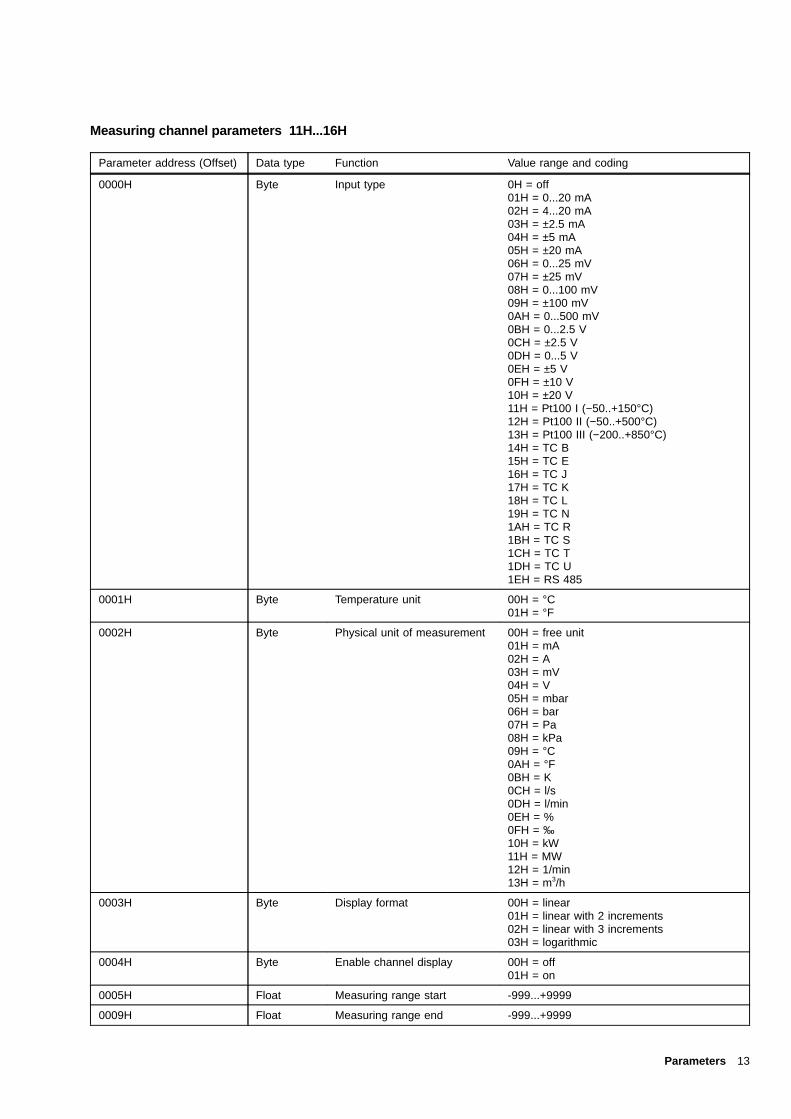
0000H Byte Input type 0H = off01H = 0...20 mA02H = 4...20 mA03H = ±2.5 mA04H = ±5 mA05H = ±20 mA06H = 0...25 mV07H = ±25 mV08H = 0...100 mV09H = ±100 mV0AH = 0...500 mV0BH = 0...2.5 V0CH = ±2.5 V0DH = 0...5 V0EH = ±5 V0FH = ±10 V10H = ±20 V11H = Pt100 I (−50..+150°C)12H = Pt100 II (−50..+500°C)13H = Pt100 III (−200..+850°C)14H = TC B15H = TC E16H = TC J17H = TC K18H = TC L19H = TC N1AH = TC R1BH = TC S1CH = TC T1DH = TC U1EH = RS 485
0001H Byte Temperature unit 00H = °C01H = °F
0002H Byte Physical unit of measurement 00H = free unit01H = mA02H = A03H = mV04H = V05H = mbar06H = bar07H = Pa08H = kPa09H = °C0AH = °F0BH = K0CH = l/s0DH = l/min0EH = %0FH = ‰10H = kW11H = MW12H = 1/min13H = m3/h
0003H Byte Display format 00H = linear01H = linear with 2 increments02H = linear with 3 increments03H = logarithmic
0004H Byte Enable channel display 00H = off01H = on
0005H Float Measuring range start -999...+9999
0009H Float Measuring range end -999...+9999
Parameters 13

Parameter address (Offset) Data type Function Value range and coding
000DH Float Display range start -999...+9999; 1,00E-9...9,99E+9 forlogarithmic display range
0011H Float Display range end -999...+9999; 1,00E-9...9,99E+9 forlogarithmic display range
0015H Float 1st tie point for non-lineardisplay rangemeasured range value
-999...+9999
0019H Float 1st tie point for non-lineardisplay rangeDisplay range value
-999...+9999
001DH Float 2nd tie point for non-lineardisplay rangeMeasured range value
-999...+9999
0021H Float 2nd tie point for non-lineardisplay rangeDisplay range value
-999...+9999
0025H Float Results range lower rangevalue
-999...+9999
0029H Float Results range upper rangevalue
-999...+9999
002DH Byte Recording range start 0...90
002EH Byte Recording range end 10...100
002FH Integer Offset measured value correct. -1000...+1000
0033H Byte Filter time 00...3CH = 0...60 s
0034H Byte Recording direction 00H = no01H = yes
0035H Byte Square root extraction 00H = off01H = on
0036 Byte Reference junctiontemperature
00H = 0 °C01H = 20 °C02H = 50 °C03H = 60 °C04H = 70 °C05H = internal06H = Channel 6
0037H Byte Number of decimal places formeasured value representationin the display
00H = Floating point01H = 002H = 103H = 204H = 3
0038H Byte Pt100 connection 00H = 2-wire01H = 3-wire
0039H Float Line resistance 0....40 Ω
003DH Byte Procedure in the event of asensor break
00H = measuring signal = 0%01H = measuring signal = 100%
003EH Byte Enable break monitoring 00H = off01H = on
003FH Byte Fixed line resistance for Pt100 2-wire circuit
00H = specify resistance01H = measure resistance
0041H Byte Assignment of scale LED 00H = none01H = LED 1 top02H = LED 203H = LED 304H = LED 405H = LED 506H = LED 6 bottom
14 Parameters

Parameter address (Offset) Data type Function Value range and coding
0042H Byte Mathematical functions 00H = off01H = Addition02H = Subtraction
0043H Byte Logic channel 1 00H = Channel 102H = Channel 203H = Channel 304H = Channel 405H = Channel 506H = Channel 6
0044H Byte Logic channel 2 00H = Channel 102H = Channel 203H = Channel 304H = Channel 405H = Channel 506H = Channel 6
0046H Float Threshold 1 -999...9999; 1,00E-9...9,99E+9 for logarithmicdisplay range
004AH Float Threshold 2 -999...9999; 1,00E-9...9,99E+9 for logarithmicdisplay range
004EH Byte Effective direction threshold 1 00H = min01H = max
004FH Byte Effective direction threshold 2 00H = min01H = max
0050H Byte Relay output for threshold 1 00H = off01H = DO 1...14H = DO 20
0051H Byte Relay output for threshold 2 00H = off01H = DO 1...14H = DO 20
0052H Byte Text line for threshold 1 00H = none01H = Text line 1...0AH = Text line 10
0053H Byte Text line for threshold 1 as for threshold 1
0056H Byte Accounting: Mode 00H = off01H = Mean02H = Sum03H = Sum and threshold
0057H Byte Accounting: External control 00H = off01H = DI 1...0EH = DI 14
0058H Byte Accounting interval 00H = 15 min01H = 30 min02H = 1 h03H = 2 h04H = 6 h05H = 8 h06H = 12 h07H = 1 d08H = 7 d09H = 1 month
0059H Word Synchronisation time = starttime interval
Hour (high byte)00...17H = 0...23Minute (low byte)00...3BH = 0...59
Parameters 15
Parameter address (Offset) Data type Function Value range and coding
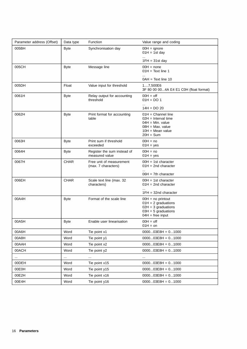
005BH Byte Synchronisation day 00H = ignore01H = 1st day...1FH = 31st day
005CH Byte Message line 00H = none01H = Text line 1...0AH = Text line 10
005DH Float Value input for threshold 1....7,500E63F 80 00 00...4A E4 E1 C0H (float format)
0061H Byte Relay output for accountingthreshold
00H = off01H = DO 1...14H = DO 20
0062H Byte Print format for accountingtable
01H = Channel line02H = Interval time04H = Min. value08H = Max. value10H = Mean value20H = Sum
0063H Byte Print sum if thresholdexceeded
00H = no01H = yes
0064H Byte Register the sum instead ofmeasured value
00H = no01H = yes
0067H CHAR Free unit of measurement(max. 7 characters)
00H = 1st character01H = 2nd character...06H = 7th character
006EH CHAR Scale text line (max. 32characters)
00H = 1st character01H = 2nd character...1FH = 32nd character
00A4H Byte Format of the scale line 00H = no printout01H = 2 graduations02H = 3 graduations03H = 5 graduations04H = free input
00A5H Byte Enable user linearisation 00H = off01H = on
00A6H Word Tie point x1 0000...03E8H = 0...1000
00A8H Word Tie point y1 0000...03E8H = 0...1000
00AAH Word Tie point x2 0000...03E8H = 0...1000
00ACH Word Tie point y2 0000...03E8H = 0...1000
... ... ... ...
00DEH Word Tie point x15 0000...03E8H = 0...1000
00E0H Word Tie point y15 0000...03E8H = 0...1000
00E2H Word Tie point x16 0000...03E8H = 0...1000
00E4H Word Tie point y16 0000...03E8H = 0...1000
16 Parameters
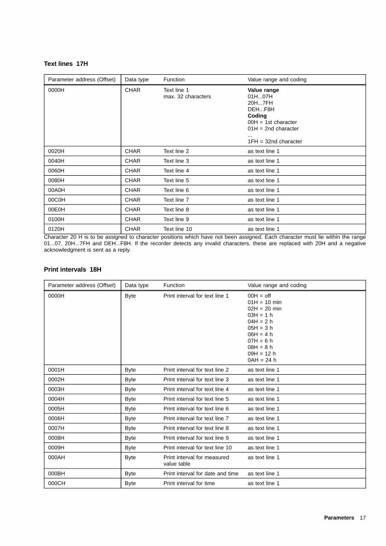
Text lines 17H
Parameter address (Offset) Data type Function Value range and coding
0000H CHAR Text line 1max. 32 characters
Value range01H...07H20H...7FHDEH...F8HCoding00H = 1st character01H = 2nd character...1FH = 32nd character
0020H CHAR Text line 2 as text line 1
0040H CHAR Text line 3 as text line 1
0060H CHAR Text line 4 as text line 1
0080H CHAR Text line 5 as text line 1
00A0H CHAR Text line 6 as text line 1
00C0H CHAR Text line 7 as text line 1
00E0H CHAR Text line 8 as text line 1
0100H CHAR Text line 9 as text line 1
0120H CHAR Text line 10 as text line 1Character 20 H is to be assigned to character positions which have not been assigned. Each character must lie within the range01...07, 20H...7FH and DEH...F8H. If the recorder detects any invalid characters, these are replaced with 20H and a negativeacknowledgment is sent as a reply.
Print intervals 18H
Parameter address (Offset) Data type Function Value range and coding
0000H Byte Print interval for text line 1 00H = off01H = 10 min02H = 20 min03H = 1 h04H = 2 h05H = 3 h06H = 4 h07H = 6 h08H = 8 h09H = 12 h0AH = 24 h
0001H Byte Print interval for text line 2 as text line 1
0002H Byte Print interval for text line 3 as text line 1
0003H Byte Print interval for text line 4 as text line 1
0004H Byte Print interval for text line 5 as text line 1
0005H Byte Print interval for text line 6 as text line 1
0006H Byte Print interval for text line 7 as text line 1
0007H Byte Print interval for text line 8 as text line 1
0008H Byte Print interval for text line 9 as text line 1
0009H Byte Print interval for text line 10 as text line 1
000AH Byte Print interval for measuredvalue table
as text line 1
000BH Byte Print interval for date and time as text line 1
000CH Byte Print interval for time as text line 1
Parameters 17

Synchronisation times for text output 19H
Parameter address (Offset) Data type Function Value range and coding
0000H Word Synchronisation time for cy-clical printing of text line 1
Hour (high byte)00...23 = 00...17HMinute (low byte)00...59 = 00...3BH
0002H Word ... of text line 2 as text line 1
0004H Word ... of text line 3 as text line 1
0006H Word ... of text line 4 as text line 1
0008H Word ... of text line 5 as text line 1
000AH Word ... of text line 6 as text line 1
000CH Word ... of text line 7 as text line 1
000EH Word ... of text line 8 as text line 1
0010H Word ... of text line 9 as text line 1
0012H Word ... of text line 10 as text line 1
0014H Word ... of measured value table as text line 1
0016H Word ... of date and time as text line 1
0018H Word ... of time as text line 1The recorder also processes synchronisation times in the 24-hour format for US data format.
Print colours 1AH
Parameter address (Offset) Data type Function Value range and coding
0000H Byte Print colour for measuringchannnel 1
00H = none01H = violet02H = red03H = black04H = green05H = blue06H = brown
0001H Byte Print colour for measuringchannnel 2
as measuring channel 1
0002H Byte Print colour for measuringchannnel 3
as measuring channel 1
0003H Byte Print colour for measuringchannnel 4
as measuring channel 1
0004H Byte Print colour for measuringchannnel 5
as measuring channel 1
0005H Byte Print colour for measuringchannnel 6
as measuring channel 1
0006H Byte Print colour for text line 1 as measuring channel 1
0007H Byte Print colour for text line 2 as measuring channel 1
0008H Byte Print colour for text line 3 as measuring channel 1
0009H Byte Print colour for text line 4 as measuring channel 1
000AH Byte Print colour for text line 5 as measuring channel 1
000BH Byte Print colour for text line 6 as measuring channel 1
000CH Byte Print colour for text line 7 as measuring channel 1
000DH Byte Print colour for text line 8 as measuring channel 1
000EH Byte Print colour for text line 9 as measuring channel 1
000FH Byte Print colour for text line 10 as measuring channel 1
18 Parameters
Parameter address (Offset) Data type Function Value range and coding
0010H Byte Print colour for measuredvalue table
as measuring channel 1
0011H Byte Print colour for date and time 00H = none01H = violet02H = red03H = black04H = green05H = blue06H = brown07H = daily alternately
0012H Byte Print colour for time as for date and time
Di assignment 1BH
Parameter address (Offset) Data type Function Value range and coding
0000H Byte Activate event marker 1 00H = off01H = DI 1..0EH = DI 14
0001H Byte Activate event marker 2 as event marker 1
0002H Byte activate event marker 3 as event marker 1
0003H Byte Aactivate event marker 4 as event marker 1
0004H Byte Trigger printout of text line 1 as event marker 1
0005H Byte Trigger printout of text line 2 as event marker 1
0006H Byte Trigger printout of text line 3 as event marker 1
0007H Byte Trigger printout of text line 4 as event marker 1
0008H Byte Trigger printout of text line 5 as event marker 1
0009H Byte Trigger printout of text line 6 as event marker 1
000AH Byte Trigger printout of text line 7 as event marker 1
000BH Byte Trigger printout of text line 8 as event marker 1
000CH Byte Trigger printout of text line 9 as event marker 1
000DH Byte Trigger printout of text line 10 as event marker 1
000EH Byte Trigger printout of measuredvalue table
as event marker 1
000FH Byte Trigger printout of date andtime
as event marker 1
0010H Byte Enable parameterisation as event marker 1
0011H Byte External selection speed 1 to 2 as event marker 1
0012H Byte Control input for synchronisa-tion of clock
as event marker 1
0013H Byte Delete printer queue as event marker 1
0014H Byte Activate standby as event marker 1
Parameters 19
Date and time 1CH
Parameter address (Offset) Data type Function Value range and coding
0000H Byte Day 01...1FH = 1...31
0001H Byte Month 01...12H = 1...12
0002H Byte Year 00...63H = 0...99
0003H Byte Hour 00...17H = 0...23
0004H Byte Minute 00...3BH = 0...59
Calibration data 1DH[Data can only be read]
Parameter address (Offset) Data type Function Value range and coding
0000H Word Lower range value, channel 1 0000...FFFF
0002H Word Upper range value, channel 1 0000...FFFF
0004H Word Lower range value, channel 2 0000...FFFF
0006H Word Upper range value, channel 2 0000...FFFF
0008H Word Lower range value, channel 3 0000...FFFF
000AH Word Upper range value, channel 3 0000...FFFF
000CH Word Lower range value, channel 4 0000...FFFF
000EH Word Upper range value, channel 4 0000...FFFF
0010H Word Lower range value, channel 5 0000...FFFF
0012H Word Upper range value, channel 5 0000...FFFF
0014H Word Lower range value, channel 6 0000...FFFF
0016H Word Upper range value, channel 6 0000...FFFF
0018H Word O-point offset print head 0...100
001AH Word Total number of increments 980...1000
001CH Word O-point offset scale 0...100
Channel measured values and instrument status 1EH[Data can only be read]
Parameter address (Offset) Data type Function Value range and coding
0000H Float Measured value, channel 1
0004H Float Measured value, channel 2
0008H Float Measured value, channel 3
000CH Float Measured value, channel 4
0010H Float Measured value, channel 5
0014H Float Measured value, channel 6
0018H Byte Status of DI binary inputs onthe recorder
Bit0 DI 11 DI 22 DI 33 DI 44 DI 55 DI 66 DI xx7 DI xx
20 Parameters
0019H Byte Status of DI binary inputs viaIO converter
Bit0 DI 71 DI 82 DI 93 DI 104 DI 115 DI 126 DI 137 DI 14
001AH Byte Status of DO binary outputs onthe recorder
Bit0 DO 11 DO 22 DO 33 DO 44 DO 55 DO 66 DO xx7 DO xx
001BH Word Status of DO binary outputsvia IO converter
Bit0 DO 71 DO 82 DO 93 DO 104 DO 115 DO 126 DO 137 D0 148 DO 159 DO 16A DO 17B DO 18C DO 19D D0 20
001DH D-Word Device alarm status Bit0001 CPU error02 Internal RAM error03 External RAM error on CPU card04 Communication error between CPU and
clock05 A/D converter error06 Check sum error, parameter data CPU
card07 Reading error with EEPROM on CPU
card08 Writing error with EEPROM CPU card09 Check sum error, calibration data channel
card0A Reading error with EEPROM on channel
card0B Writing error with EEPROM channel card0C Watchdog generates device reset0D Printer queue full0E Print head stuck0F Voltage interruption to clock module
10 Speed too high for text output11 Oscillator watchdog generates device
reset12 Communication error with IO converter13 Check sum error F-RAM14 Reading error with F-RAM15 Writing error with F-RAM16 Error, reference junction correction
0021H D-Word Device alarm:acknowledgment status
as for device alarm status
Parameters 21
0025H D-Word Thresholds: alarm status Bit0 Threshold 1, channel 11 Threshold 1, channel 22 Threshold 1, channel 33 Threshold 1, channel 44 Threshold 1, channel 55 Threshold 1, channel 66 xx7 xx8 Threshold 2, channel 19 Threshold 2, channel 2A Threshold 2, channel 3B Threshold 2, channel 4C Threshold 2, channel 5D Threshold 2, channel 6
0029H D-Word Thresholds: acknowledgmentstatus
as for thresholds alarm status
002DH Byte Device type 00H = scale version01H = LC display02H = LED display
002EH Byte Thresholds 00H = none01H = installed
002FH Byte Remaining paper length 0000...0C80H = 0....3200 cm
0031H Byte Standby status 00H = Recording operation01H = Standby
0032H Byte Status measuring channel 1 Bit0 = Overflow1 = Underflow2 = Reserved3 = Reserved4 = Line break, display 05 = Line break, display 100
0033H Byte Status measuring channel 1 as status for measuring channel 1
0034H Byte Status measuring channel 1 as status for measuring channel 1
0035H Byte Status measuring channel 1 as status for measuring channel 1
0036H Byte Status measuring channel 1 as status for measuring channel 1
0037H Byte Status measuring channel 1 as status for measuring channel 1
0038H D-Word Counter for hours of operation Operating time in minutes (hex coded)
Entering measured values into recorder 1FH
Measured values are entered into the recorder using an SD2type message. The parameter field address 1FH is to be usedas the basic address.
The measured values are transmitted in the form of standardisedvalues. The permitted range of numbers is 0...1000. The recor-der does not accept values that lie outside this range. If invalidmeasured values are received, the message is answered with anegative acknowledgment. The data contained in the messageare only processed by the recorder if the corresponding channelis parameterised to the “SER” type of measurement. The datareceived are ignored in the case of other types of measurement.
The message format is:
SD2/LE/LEr/SD2/DA/SA/FC/aa/oo/oo/cc/datafield/FCS/ED|<-- L -->|
Where:
SD2 = 68HStart byte
LE Number of data bytes + 7
LEr Repetition of LESD2 = 68H
Repetition of start byteDA Destination address (bus subscriber address)SA Source addressFC Function code (16H = write)aa Basic address of parameter field 1FHbb High byte of the offset = 0cc Low byte of the offsetsdd Number of data bytesee Data bytesFCS Test byte (Frame Check Sequence)
Sum of the hex value of the L frame without transfor-mation for FFH
ED = 16HEnd byte (End Delimiter), code: 16H
L Number of bytes in FCS
22 Parameters
Parameter address (Offset) Data type Function Value range and coding
0000H Word Measured values channel 1 0000H...3E8H = 0...1000
0002H Word Measured values channel 2 0000H...3E8H = 0...1000
0004H Word Measured values channel 3 0000H...3E8H = 0...1000
0006H Word Measured values channel 4 0000H...3E8H = 0...1000
0008H Word Measured values channel 5 0000H...3E8H = 0...1000
000AH Word Measured values channel 6 0000H...3E8H = 0...1000
Reading accounting data 20H
The accounting data are interrogated by means of an SD3 inter-rogation to basic address 20H. The data of a measuring channelare transmitted in blocks with a message. It is not possible toaccess individual parameters of the accounting function. Theoffset which is sent in the interrogation determines the numberof the measuring channel whose data are to be read. The bytenumber is to be entered into the interrogation in accordance withthe data field size.
SD3/DA/SA/FC/aa/bb/bb/cc/xx/xx/xx/xx/FCS/ED|<-- L -->|
Where:
SD3 = A2HStart byte
DA Destination address (bus subscriber address)SA Source addressFC = 15H
Function codeaa = 20H
Basic address of the parameter fieldbb bb 2 bytes parameter address (offset)cc = 27H
Number of data bytesxx xxxx xx 4 random bytesFCS Test byte (Frame Check Sequence)
Sum of the hex value of the L frame without transfor-mation for FFH
ED = 16HEnd byte (End Delimiter), code: 16H
L Number of bytes in FCS
Parameter address (Offset) Data type Function Value range and coding
0000H Block Accounting data to measuringchannel 1
0001H Block Accounting data to measuringchannel 2
0002H Block Accounting data to measuringchannel 3
0003H Block Accounting data to measuringchannel 4
0004H Block Accounting data to measuringchannel 5
0005H Block Accounting data to measuringchannel 6
The recorder sends an SD2 type reply telegram. In this telegram, the parameters have the following meanings:
Parameter address (Offset) Data type Function Value range and coding
0000H Byte Accounting interval
0001H Float Minimum
0005H Float Maximum
0009H Float Mean value
000DH Float Accounting sum
0011H Byte Starting day of the interval
Parameters 23
0012H Byte Starting month of the interval
0013H Byte Starting year of the interval
0014H Byte Starting hour of the interval
0015H Byte Starting minute of the interval
0016Hbis001AH
Byte Time and date, minimum
001BHbis001FH
Byte Time and date, maximum
0020Hbis0025H
Byte Current time and current date
0026H Byte Mode of accounting
Writing device status 21H
This parameter field address is used for entering the length ofthe new roll of paper after changing the chart paper.
It is possible to excite the channel-specific line pairs (scale lineand text line) such that they are printed out immediately.
Parameter address (Offset) Data type Function Value range and coding
0000H Word Paper length (entry in cm) 0000H = do not change0001H...0C80H = 1...3200
0006H Byte Save parameterisation imme-diately
00H = no01H = yes
0007H Byte Print line pair immediately 00H = none01H = line 102H = line 203H = line 304H = line 405H = line 506H = line 6
24 Parameters
Creating text blocksIf variable parameters are to be printed at the start and end of abatch process (precondition: the printer channel is installed inrecorder), complete text lines can be sent to the recorder withthe parameter field address F1H.
Send printout lines to recorder(with parameter field address F1H)
It is with this message that a text line with 32 characters is sentto the recorder. The recorder enters the message in the printerqueue. As soon as the queue is empty, text printout beginsimmediately, otherwise the text lines stored in the queue areprinted first. The recorder acknowledges the message with theacknowledgment code 10H, if the message is received correctlyand entered into the queue. If the queue has no more freespace, the acknowledgement code 11H is sent in response.
The message format is:
SD2/LE/LEr/SD2/DA/SA/FC/aa/bb/cc/dd/ee/ff/[Text line]/FCS/ED|<-- L -->|
Where:
SD2 = 68HStart byte
LE Number of data bytes + 7LEr Repetition of LESD2 = 68H
Repetition of start byteDA Target address (bus subscriber address)SA Source addressFC = 16H
Function codeaa = F1H
Basic address of the parameter fieldbb = 00H
Fill bytecc = 00H
Fill bytedd Length of the text line + 2ee Date control
00H = print text without date / without time01H = print text with time02H = print text with date03H = print text with date / with time
ff Print colour00H = none01H = violet02H = red03H = black04H = green05H = blue
[Textline] Contents of the text line max. 32 ASCII charactersFCS Test byte (Frame Check Sequence)
Sum of the hex value of the L frame without transfor-mation for FFH
ED = 16HEnd byte (End Delimiter), code: 16H
L Number of bytes in FCS
Creating text blocks 25
Scanning of the printout statusThe number of lines in the printout queue is scanned by therecorder with:
SD3/DA/SA/FC/aa/oo/oo/cc/xx/xx/xx/xx/FCS/ED|<-- L -->|
Where:
SD3 = A2HStart byte
DA Target address (bus subscriber address)SA Source addressFC = 15H
Function codeaa = F1H
Basic address of the parameter fieldoooo = 00 00H
2 bytes of parameter address (Offset)cc = 01H
Number of scanned data bytesxx xxxx xx 4 random bytesFCS Test byte (Frame Check Sequence)
Sum of the hex value of the L frame without transfor-mation for FFH
ED = 16HEnd byte (End Delimiter), code: 16H
L Number of Bytes in FCS
The answer of the recorder is:
SD2/LE/LEr/SD2/DA/SA/FC/aa/FCS/ED
Where:
SD2 = 68HStart byte
LE Number of data bytes + 3LEr Repetition of LESD2 = 68H
Repetition of start byteDA Target address (bus subscriber address)SA Source addressFC = 15H
Function codeaa Number of information items in the queueFCS Test byte (Frame Check Sequence)
Sum of the hex value of the L frame without transfor-mation for FFH
ED = 16HEnd byte (End Delimiter), code: 16H
L Number of bytes in FCS
Sending a display line to the recorder F2HThis message is used to send a text line with max. 16characters to the recorder. The message appears on the displayif the control byte is set to the value 01H.
The message format is:
SD2/LE/LEr/SD2/DA/SA/FC/aa/bb/cc/dd/ee/[Text line]/FCS/ED|<-- L -->|
Where:
SD2 = 68HStart byte
LE = 17HNumber of data bytes + 7
LEr Repetition of LESD2 = 68H
Repetition of start byteDA Target address (bus subscriber address)SA Source addressFC = 16H
Function codeaa = F2H
Basic address of the parameter fieldbb = 00H
Fill bytecc = 00H
Fill bytedd Length of the text line + 1ee Control for display
00H = do not display text01H = display text
Text-line Contents of the text line max. 16 ASCII charactersFCS Test byte (Frame Check Sequence)
Sum of the hex value of the L frame without transfor-mation for FFH
ED = 16HEnd byte (End Delimiter), code: 16H
L Number of bytes in FCS
26 Creating text blocks

Communication error register FFHThe communication error registers are used for making errordiagnostics in case of communication problems which occurwhen invalid values are transmitted.
The error registers are scanned by the recorder with:
SD3/DA/SA/FC/aa/oo/oo/cc/xx/xx/xx/xx/FCS/ED|<-- L -->|
Where:
SD3 = A2HStart byte
DA Target address (bus subscriber address)SA Source addressFC = 15H
Function codeaa = FFH
Basic address of the parameter fieldoooo = 00 00H
2 bytes parameter address (offset)cc = 09H
Number of scanned data bytesxx xxxx xx 4 random bytesFCS Test byte (Frame Check Sequence)
Sum of the hex value of the L frame without transfor-mation for FFH
ED = 16HEnd byte (End Delimiter), code: 16H
L Number of Bytes in FCS
The answer of the recorder is:
SD2/LE/LEr/SD2/DA/SA/FC/aa/bb/cc/dd/ee/FCS/ED
Where:
SD2 = 68HStart byte
LE = 17HNumber of data bytes + 7
LEr Repetition of LESD2 = 68H
Repetition of start byteDA Target address (bus subscriber address B)SA Source addressFC = 15H
Function codeaa requested data field lengthbb Type of error
00H = no error01H = incorrect basic field address02H = incorrect offset03H = incorrect value04H = incorrect length05H = Header error06H = incorrect function code
cc Field address of where error occureddd Offset at which error occuredee 4 bytes copy of the incorrect valueFCS Test byte (Frame Check Sequence)
Sum of the hex value of the L frame without transfor-mation for FFH
ED = 16HEnd byte (End Delimiter), code: 16H
L Number of bytes in FCS
Creating text blocks 27
Connection of the recorder to WIZCONThe function codes and parameter addresses below are forestablishing a connection between the recorder and WIZCON.
The function codes used by the driver software “VPIDC.COM”are supported here.
Interrogation of 8 values(with telegram SD3 and function code 04H)
is used to send a query to the recorder.
The query sent to the recorder has the following format:
SD3/DA/SA/FC/a1/a2/a3/a4/a5/a6/a7/a8/FCS/ED|<-- L -->|
Where:
SD3 = A2HStart byte
DA Destination address (bus subscriber address)SA Source addressFC = 04H
Function codea1....a8 Parameter addresses from Section “Parameter addres-
ses”FCS Test byte (Frame Check Sequence)
Sum of the hex value of the L frame without transfor-mation for FFH
ED = 16HEnd byte (End Delimiter), code: 16H
L Number of bytes in FCS
The addresses permitted for a1...a8 are listed in section “Para-meter addresses”. If the same value is entered for two succes-sive address fields, the data of the repeated address and allfollowing data are omitted.
The recorder answer is:
SD2 LE LEr SD2 DA SA 04H value1 value2 ... value8 FCS ED
The max. 8 values correspond to the addresses entered in thequery. Each value is represented by 16 bits. The values aretransmitted in the order High Byte / Low Byte.
Modification of 2 values(with telegram SD3 and function code 07H)
The computer query is:
SD3/DA/SA/FC/c1/a1/val1/c2/a2/val2/FCS/ED|<-- L -->|
Where:
SD3 = A2HStart byte
DA Destination address (bus subscriber address)SA Source addressFC = 07H
Function codec1 = 01H
Triggers modification in devicea1 Parameter address from section „Parameter addresses“val1 Parameter valuec2 = 01H
triggers modification in the devicea2 Parameter address from section „Parameter addresses“val2 Parameter valueFCS Test byte (Frame Check Sequence)
Sum of the hex value of the L frame without transfor-mation for FFH
ED = 16HEnd byte (End Delimiter), code: 16H
L Number of bytes in FCS
c1 or c2 is the code which decides whether the value is to beactually modified. The new value is taken over by the recorder ifthe code is 01H or 02H. No other value for c1 or c2 triggers anaction. Parameters a1/a2 are the corresponding parameter ad-dresses. The new values (16 bit) have been entered into themessage for val1/val2, with the order High Byte / Low Byte.
The recorder answer is:
SD1 DA SA qq FCS ED.
Here qq is the acknowledge code of the recorder.
If qq = 10H, the message has been processed without error. Theacknowledge code 11H is sent in the event of an error. Repeatthe entries for val 1 as val 2 if only one value is to be changedin the recorder (WIZCON only permits modification of one value).
28 Connection of the recorder to WIZCON
Numerical formatsAnalog values are transmitted in a standardized format, withscale start = 0 ‰ and scale end = 1000 ‰ being used as refe-rence values. Hence all values possible are within the range 0 to1000. Negative values cannot occur. The hexadecimal valueassigned to a decimal per mille value is calculated as follows:
Hex value = per mille value * 16 + 32768
Example
The measured value of a channel is 87 °C (= val) in ameasuring range between −50 °C (= low) and +150 °C (= high).
Hex value = (val-low) / (high-low) * 1000 * 16 + 32768 = AAD0H
Example
Speed 1 = 240 mm/h → index = 08H (from section “Systemparameters”).
transmitted value = index * 16 + 32768 = 8080H
Parameter addresses for function codes 04H and 07H
Parameter address Contents
00H01H02H03H04H05H06H07H08H09H0AH0BH0BH
Measured value, channel 1(standardised)
..., channel 6 (standardised)Speed index 1Speed index 2Day of recorder-internal clockMonthYearHourMinute
10H11H12H
13H
14H
15H
Thresholds for channel 1Threshold 1 (standardised)Threshold 2 (standardised)Function threshold 1 (0 = min., 1= max.)Function threshold 1 (0 = min., 1= max.)Relay output for threshold 1(0...20)Relay output for threshold 1(0...20)
18H19H1AH
1BH
1CH
1DH
Thresholds for channel 2Threshold 1 (standardised)Threshold 2 (standardised)Function threshold 1 (0 = min., 1= max.)Function threshold 1 (0 = min., 1= max.)Relay output for threshold 1(0...20)Relay output for threshold 1(0...20)
Parameteradresse Inhalt
20H21H22H
23H
24H
25H
Thresholds for channel 3Threshold 1 (standardised)Threshold 2 (standardised)Function threshold 1 (0 = min., 1= max.)Function threshold 1 (0 = min., 1= max.)Relay output for threshold 1(0...20)Relay output for threshold 1(0...20)
28H...2DHThresholds for channel 4as channel 3
30H...35HThresholds for channel 5as channel 3
38H...3DHThresholds for channel 6as channel 3
Connection of the recorder to WIZCON 29
Interrogation of binary information(with telegram SD3 and function code 05H)
Is used to send a query to the recorder. The values transmittedwith function code 05 are not converted acc. to the numericalformat for analog values, since the information involved here isexclusively binary information. The recorder uses one byte in theanswer message for each parameter address queried. Bits notin use are set to 0 by the recorder.
The computer’s query to the recorder is:
SD3/DA/SA/FC/aa/cc/xx/xx/xx/xx/xx/xx/FCS/ED|<-- L -->|
The following applies:
SD3 = A2HStart byte
DA Destination address (bus subscriber address)SA Source addressFC = 05H
Function codeaa Start address = Parameter address from section
„Parameter addresses“cc Number of data bytesxx......xx 6 arbitrary bytesFCS Test byte (Frame Check Sequence)
Sum of the hex value of the L frame without transfor-mation for FFH
ED = 16HEnd byte (End Delimiter), code: 16H
L Number of bytes in FCS
The recorder’s answer is:
SD2 LE LEr SD2 DA SA 05H Byte 1 Byte 2 ... Byte n FCS ED
Parameter addresses for function code 05H
Parameteraddress
Contents
00H01H02H03H04H05H06H
07H
08H
Threshold status, channel 1 to 4Threshold status, channel 5 and 6Status DIStatus DOEquipment self-test status, bits 0...7Equipment self-test status, bits 8...15Equipment self-test status, bits16...23Equipment self-test status, bits24...31Parameterisation status(01 = recorder is in parameterisationmode, it is not possible to modify theparameterisation via the interface)
The threshold status of channels 1 to 4 is stored in one byte:
Bit7 Threshold 1 channel 16 Threshold 2 channel 15 Threshold 1 channel 24 Threshold 2 channel 23 Threshold 1 channel 32 Threshold 2 channel 31 Threshold 1 channel 40 Threshold 2 channel 4
The threshold status of channels 5 and 6 is stored in an additio-nal byte:
Bit..3 Threshold 1 channel 52 Threshold 2 channel 51 Threshold 1 channel 60 Threshold 2 channel 6
The status of the binary inputs is stored in the lower 6 bits of abyte:
Bit..5 DI 1 active4 DI 2 active3 DI 3 active2 DI 4 active1 DI 5 active0 DI 6 active
The status of the binary outputs is stored in the lower 6 bits of abyte:
Bit..5 DO 1 active4 DO 2 active3 DO 3 active2 DO 4 active1 DO 5 active0 DO 6 active
30 Connection of the recorder to WIZCON
Character set tableCharacter Code
[dec] [Hexdec]Character Code
[dec] [Hexdec]
2 01 01 A 65 41
3 02 02 B 66 42
‰ 03 03 C 67 43
↑ 04 04 D 68 44
↓ 05 05 E 69 45
06 06 F 70 46
10 07 07 G 71 47
H 72 48
32 20 I 73 49
! 33 21 J 74 4A
" 34 22 K 75 4B
# 35 23 L 76 4C
$ 36 24 M 77 4D
% 37 25 N 78 4E
& 38 26 O 79 4F
’ 39 27 P 80 50
( 40 28 Q 81 51
) 41 29 R 82 52
* 42 2A S 83 53
+ 43 2B T 84 54
, 44 2C U 85 55
- 45 2D V 86 56
. 46 2E W 87 57
/ 47 2F X 88 58
0 48 30 Y 89 59
1 49 31 Z 90 5A
2 50 32 [ 91 5B
3 51 33 \ 92 5C
4 52 34 ] 93 5D
5 53 35 ^ 94 5E
6 54 36 _ 95 5F
7 55 37 ‘ 96 60
8 56 38 a 97 61
9 57 39 b 98 62
: 58 3A c 99 63
; 59 3B d 100 64
< 60 3C e 101 65
= 61 3D f 102 66
> 62 3E g 103 67
? 63 3F h 104 68
@ 64 40 i 105 69
Character Code[dec] [Hexdec]
Character Code[dec] [Hexdec]
j 106 6A ä 225 E1
k 107 6B β 226 E2
l 108 6C 227 E3
m 109 6D µ 228 E4
n 110 6E σ 229 E5
o 111 6F ς 230 E6
p 112 70 g withUnterl.
231 E7
q 113 71 232 E8
r 114 72 -1 233 E9
s 115 73 j 234 EA
t 116 74 235 EB
u 117 75 φ 236 EC
v 118 76 £ 237 ED
w 119 77 ñ 238 EE
x 120 78 ö 239 EF
y 121 79 p 240 F0
z 122 7A q 241 F1
123 7B Θ 242 F2
| 124 7C ∞ 243 F3
125 7D Ω 244 F4
→ 126 7E ü 245 F5
← 127 7F Σ 246 F6
~ 222 DE π 247 F7
° 223 DF 248 F8
α 224 E0
x
Character set table 31

Subject to technical changes.
This technical documentation is protected by copyright. Translating, photocopying and diseminating it in any form whatsoever - eveneditings or excerpts thereof - especially as reprint, photomechanical or electronic reproduction or storage on data processing systems ornetworks is not allowed without the permission of the copyright owner and non-compliance will lead to both civil and criminal prosecution.
ABB Automation Products GmbHHöseler Platz 2D-45279 HeiligenhausPhone +49 (0)20 56) 92 - 51 81Fax +49 (0)20 56) 92 - 50 81http://www.abb.com
Subject to technical changes.Printed in the Fed. Rep. of Germany
42/41-25 EN Rev. 0.0Edition 02.01