pneumatic electric tire changer •operator’s manual - snapon.com · iv updating reports 0 this...
TRANSCRIPT
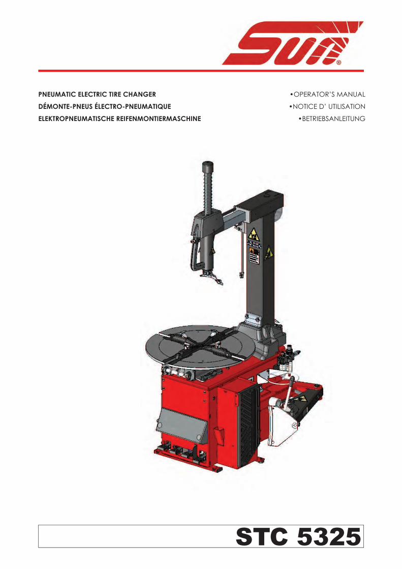
STC 5325
PNEUMATIC ELECTRIC TIRE CHANGER
DÉMONTE-PNEUS ÉLECTRO-PNEUMATIQUE
ELEKTROPNEUMATISCHE REIFENMONTIERMASCHINE
•OPERATOR’S MANUAL
•NOTICE D’ UTILISATION
•BETRIEBSANLEITUNG
ii
All Information in this manual has been supplied by the indicated Snap-on Technical Department:Toutes les informations fi gurant dans le présent manuel ont été fournies par le Bureau Technique indiqué :
Alle in diesem Handbuch enthaltenen Informationen wurden durch das angegebene Technische Büro von Snap-on geliefert:Вся информация, содержащаяся в данном руководстве, была доставлена по указанному технической офисе Snap-on:
Tutte le informazioni contenute in questo manuale sono fornite dall’Uffi cio Tecnico Snap-on indicato:Todas las informaciones contenidas en este manual han sido facilitadas por el Servicio Técnico Snap-on indicado:
Todas as informações contidas neste manual foram fornecidas pelo Servicio Técnico Snap-on indicado:
Snap-on Equipment Srl a unico socio
Via Provinciale per Carpi, 3342015 CORREGGIO (RE) ITALYTel.: +39-(0)522-733480Fax: +39-(0)522-733479
E-mail: [email protected]: http://www.snapon-equipment.eu
Correggio (RE) - ITALYFrancesco Frezza
date:
ENG - complies with all the relevant regulations in the following directives:FRA - est conforme à toutes les dispositions pertinentes des directives suivantes :DEU - Allen zu folgenden Richtlinien gehörenden Bestimmungen entspricht:ITA - è conforme a tutte le disposizioni pertinenti delle seguenti direttive: POR - satisfaz todas as disposições relevantes das seguintes directivas:SPA - es conforme con todas las disposiciones pertinentes a las siguientes directivas:ALB - është konform me të gjitha dispozitat që kanë të bëjnë me direktivat e mëposhtme:BUL - ����������! "! ��#$%# &!'(�&�)*#, ��)�&+!.# �� � �/�)�!.#�� )#&�%�#�#:CES - vyhovuje v�em po�adavk0m, které se vztahují na následující sm1rnice:HRV - udovoljava svim relevantnim odredbama slijede2ih smjernica:DAN - er i overensstemmelse med bestemmelserne i følgende direktiver:EST - vastab järgmiste direktiivide kõikidele asjassepuutuvatele sätetele:FIN - on seuraavien direktiivien asiaankuuluvien säännösten mukainen:ELL - 34567 89;<=5> ;3 ?@3J K7J MQ>W@XY37J 8Z3K7[XJ ;3 K7J 6[?@>\]3J >^_`43J:ISL - er í samræmi við allar viðeigandi tilskipanir eftirfarandi reglugerða:LAV - atbilst visiem attiecxgajiem noteikumiem �{d{s direktxv{s:LIT - atitinka visus toliau nurodyt| direktyv| reikalavimus:}~D - � �� ���/!�"��� �� �#�� "�&�# �) �/�)"#�� )#&�%�#�#:}ON - je u skladu sa svim relevantnim odredbama slede2ih direktiva:NLD - overeenstemt met alle toepasselijke voorschriften van de volgende richtlijnen:POL - jest zgodna �jest zgodny� ze wszystkimi zarz�dzeniami zawartymi w nast�puj�cych dyrektywach:RU} - este fabricat în conformitate cu toate prevederile în materie din urmãtoarele directive:SLO - vyhovuje v�etkým po�iadavkám, vz�ahujúcim sa na nasledujúce smernice:SLV - v skladu z vsemi predpisi, ki se nana�ajo na naslednje direktive:S�E - överensstämmer med alla bestämmelser tillhörande följande direktiv:TUR - a�a��da belirtilen yönetmeliklere ili�kin tüm hükümlere uygundur:HUN - megfelel a következ� irányelvekbe foglalt, valamennyi rendelkezésnek:RUS - ������������� ���� (&#��"����� "�&�!� �/�)��.#� )#&�%�#�:
ENG-The }anager of the Technical Of� ce is authorised to compile a technical lea� et in compliance with appendi� VII, letter A, of the ��������CE directive FRA-Le Responsable du Bureau Technique est autorisé à constituer le fascicule technique visé sous l¡anne�e VII lettre A de la directive ��������CE DEU-Der Leiter der technischen Abteilung ist bevollmächtigt, die technischen Unterlagen zu erstellen �siehe Anhang VII, Buchstabe A der Richtlinie ��������CE ITA-Il Responsabile dell¡Uf� cio Tecnico è autorizzato a costituire il fascicolo tecnico di cui all¡allegato VII lettera A della direttiva ��������CE POR-O Responsável do Gabinete Técnico está autorizado a compilar o processo técnico, referido no ane�o VII alínea A da directiva ��������CE SPA-El Responsable del Departamento Técnico está autorizado a constituir el fascículo técnico indicado en el ane�o VII letra A de la directiva ��������CE ALB-Përgjegjësi i ¢yrës Teknike është i autorizuar të realizojë fashikullin teknik sipas dokumentit bashkëngjitur VII germa A e direktivës ��������~E BUL-£�����&"#%�� "! ¤��"#$��%#� ��)�/ � �(�/"���.�" )! ����!�# ���"#$��%!�! *&�¥�&! � ����������#� � ¦&#/�+�"#� VII, §A¨, ©#&�%�#�! ��������Eª CES-¢odpov1dný pracovník technického odd1lení je oprávn1ný vypracovat technickou dokumentaci podle p«ílohy VII ¬ásti A Sm1rnice ��������ES HRV-Odgovorna osoba Tehni¬kog ureda je ovla�tena ustrojiti tehni¬ki svezak kako se vidi u dodatku VII slovo A smjernice ��������CE DAN-Chefen i den tekniske afdeling har tilladelse til udarbejdelse af den tekniske dokumentation jf bilag VII litra A i direktivet ��������EF EST-Tehnoosakonna vastutav töötaja on volitatud koostama tehnilise toimiku vastavalt direktiivi ��������EÜ VII lisa osale A FIN-Teknisen toimiston vastuuhenkilö on valtuutettu kokoamaan tekninen eritelmä direktiivin ��������E liitteen VII kohdan A mukaisesti ELL-® ̄ M39]\5>J K>\ °3Z57[>9 ±Q6<34>\ 34567 3²>\87>^>K_;X5>J 56 M6Q³²37 K>5 K3Z57[? <³[3@> 89;<=56 ;3 K> 8\5_;;X5> VII ̀ Q³;;6 A K_J >^_`46J ��������´µ ISL-Ábyrgðarmanni tækniskrifstofunnar er heimilt að gera tækniskjalið samkvæmt A-lið VII viðauka í reglugerð ��������EB LAV-Tehnisk{s noda¶as vadxt{js ir pilnvarots sast{dxt tehnisko dokument{ciju atbilsto�i ES direktxvas ��������E~ VII pielikuma A ieda¶ai LIT-u� technin· skyri| atsakingas asmuo yra ·galiotas sudaryti technin� byl�, kurios sudarymo tvarka nurodyta Direktyvos ��������EB VII priedo A dalyje }~D-£)����&"#�� "! ���"#$%#�� �))�/ � ��/!���" )! �� ����!�# ���"#$%#�� (&#&!$"#% )!)�" �� (&#/�� VII (#��� A �) )#&�%�#�!�! ��������CE }ON-Odgovorno lice Tehni¬kog ureda je ovla�teno da sastavi tehni¬ku fasciklu kako se vidi u dodatku VII slovo A direktive ��������CE NLD-Het Hoofd van de Technische Afdeling is gemachtigd om het technisch dossier samen te stellen waarover in Bijlage VII, afdeling A, van de richtlijn ��������EG POL-~ierownik Biura Projektowego jest upowa¸niony do za¹o¸enia skoroszytu technicznego, o którym mowa w ¢a¹�czniku VII litera A dyrektywy ��������UE RU}-Responsabilul Biroului Tehnic este autorizat sã întocmeascã dosarul tehnic prevãzut în ane�a VII litera A directiva ��������CE privind echipamentele tehnice SLO-¢odpovedný pracovník technického oddelenia je oprávnený vypracova� technickú dokumentáciu podºa prílohy VII ¬asti A Smernice ��������ES SLV-Vodja tehniènega urada je poobla�èena za sestavo tehniène mape, kot navedeno v prilogi VII, èrka A direktive ��������ES S�E-Ansvarig på det tekniska kontoret har behörighet att sammanställa medföljande teknisk dokumentation i enlighet med avsnitt A i bilaga VII i direktiv ��������EG TUR-Teknik Ofis Sorumlusu ��������EC önetmeli�i¡nin VII ekinin A harfinde belirtilen teknik dosyay� haz�rlamaya yetkilidir HUN-A }»szaki Iroda Irodavezet�je feljogosított a ��������E~ irányelv A részének VII }ellékletében meghatározott, m»szaki dokumentáció összeállításáraRUS-¼�%���)#��/½ ���"#$��%��� ��)�/! �(�/"���$�" ����!�#�½ ���"#$��%#¾ /#�� � ����������## � (&#/�+�"#�� VII, /#��& A )#&�%�#�� ��������CE
ITA-Direttore Operativo SPA-Director Operativo POR-Director Operacional ENG-Operations }anager FRA-Directeur Opérationnel DEU-Betriebsleiter ALB-Drejtori Operativ BUL-£(�&!�#��" )#&�%��& CES-Výkonný «editel HRV-Operativni direktor DAN-Driftsleder EST-Tegevdirektor FIN-Operatiivinen johtaja ELL-´M7Z37Q_876[?J ¿73\]\5KÀJ ISL-Starfandi framkvæmdarstjóri LAV-Operatxvais direktors LIT-Operacij| vadovas }~D-£(�&!�#��" )#&�%��& }ON-Operativni direktor NLD-Operationeel directeur POL-Dyrektor Operatywny RU}-Director Operator SLO-Výkonný riaditeº SLV-Operativni vodja S�E-Driftledare TUR-Â�letme }üdürü HUN-Operatív Igazgató RUS - Ã(&!�/��.#¾ (&�#'��)�����
2006/42/CE
2014/35/CE
2014/30/CE
ENG - DECLARATION OF CE CONFORMITYFRA - DECLARATION CE DE CONFORMITEDEU - KONFORMITÄTSERKLÄRUNGFIN - EY-VAATIMUSTENMUKAISUUSVAKUUTUSNLD - VERKLARING VAN OVEREENSTEMMINGSWE - EG-FÖRSÄKRAN OM ÖVERENSSTÄMMELSEDAN - EF-OVERENSSTEMMELSESERKLÆRINGISL - EB-SAMRÆMISYFIRLÝSINGPOL - DEKLARACJA ZGODNO�CI �CE�RUM - DECLARA�IE DE CONFORMITATE CU NORMELE CESLO - ES VYHLÁSENIE O ZHODESLV - IZJAVA O SKLADNOSTI CEALB - DEKLARATË KONFORMITETI KEHUN - EK MEGFELEL�SÉGI NYILATKOZAT
DICHIARAZIONE CE DI CONFORMITA� - ITADECLARAÇÃO CE DE CONFORMIDADE - POR
DECLARACIÓN CE DE CONFORMIDAD - SPA���!"#"$%& '" ()*+,�+(+,%� - BUL
ES PROHLÁ�ENÍ O SHOD. - CESDEKLARACIJA CE O PODOBNOSTI - HRV
EÜ VASTAVUSDEKLARATSIOON - EST/01230 CE 34556782303 - ELL
ES ATBILST9BAS DEKLAR:CIJA - LAVATITIKTIES DEKLARACIJA - LIT
�EC� ���!"#"$%;" '" (**<#"'=*(+ - MKDDEKLARACIJA CE O USKLA>ENOSTI - MON
EC UYGUNLUK BEYANNAMES? - TUR���!"#"$%& (**+,�+(+,%& (+"=�"#+"@ �( - RUS
Snap-on Equipment Srl - Via Provinciale per Carpi, 33 - 42015 Correggio (RE) Italy
ENG - takes full responsibility for declaring that the machineQ FRA - déclare sous sa propre responsabilité que la machine Q DEU - erklärt auf eigene VerantwortungX dass die MaschineQ ITA - dichiara sotto la propria responsabilità che la macchinaQ POR - declara sob a própria responsabilidade que a máquinaQ SPA - declara bajo su propia responsabilidad que la máquinaQ ALB - deklaron nën përgjegjësinë e tij se makineriaQ BUL - [\]^_`v`_ xz[ z{|z}z`~z�{X �\ �_�v~_{_Q CES - prohla�uje na �lastní �odpo��dnostX �e strojní �a�í�eníQ HRV - i�ja�ljuje pod �lastitom odgo�orno��u da strojQ DAN - erklærer på eget ans�arX at maskinenQ EST - kinnitab omal �astutuselX et aparaatQ FIN - �akuuttaa omalla �astuullaanX että koneQ ELL - ������� �������� ¡� � ¢�£��¤Q ISL - lýsir þ�í y¥ r á eigin ábyrgð að bíllinnQ LAV - ap�in¦damies sa�u atbild§bu apliecinaX ka ma�§na¨iek¦rtaQ LIT - prisiimdama atsakomyb© skelbiaX kad ma�inaQ MKD - vª«_}¬}_ xz[ �}z«_ z[|z}z`~z�{ [\]_ �_�v~_{_Q MON - i�ja�ljuje pod �lastitom odgo�oro��u da ma�inaQ NLD - �erklaart �oor eigen �erantwoordelijkheid dat de machineQ POL - owiadc�a na w®asn¯ odpowied�ialno�X °e mas�ynaQ RUM - declarã pe propria rãspundere cã ma±inaQ SLO - �yhlasuje na �lastnú �odpo�ednos²X �e strojo�é �ariadenieQ SLV - pod lastno odgo�ornostjo i�ja�ljamoX da je strojQ SWE - försäkrar under eget ans�ar att maskinenQ TUR - kendi sorumlulu³u alt´nda makinenin a±a³´da belirtilen yönetmeliklere uygun oldu³unu beyan etmektedirQ HUN - a saját felelµssége tudatában kijelentiX hogy a gépQ RUS - � xz^~z¶ z{}\{�{}\~~z�{·¸ ª_¹}^¹\{ �{z �_�v~_
TIRE CHANGERDEMONTE-PNEUS
REIFENMONTIERMASCHINESMONTAGOMME
DEMONTADORA DE PNEUSDESMONTADOR DE NEUMÁTICOS
ÇMONTUESE GOMASH!"#$%" &" '(!)%*"+ %" ,.!$
ZOUVA/KA PNEUMATIKDEMONTIRA/ GUMA
DÆKAFMONTERINGSMASKINEREHVIVAHETUSSEADE
RENKAANVAIHTOKONE012314 5657894:4 5981;53501<
AFFELGUNARVÉLRIEPU MONTÂÞAS IEKÂRTA
PADANGØ KEITIMO PRIETAISAS'(!)%*$="> %" ,.!$
DEMONTIRKA GUMABANDENLICHTER
URZ?DZENIE DO ZDEJMOWANIA OPONDISPOZITIV DE DEMONTAT CAUCIUCURI
VYZÚVA/KA PNEUMATÍKSNEMALEC GUM
DÄCKMONTERINGSMASKINLAST@K SÖKÜCÜGUMISZERELQ
#$%)!)%*"+%X[ \*"%)]
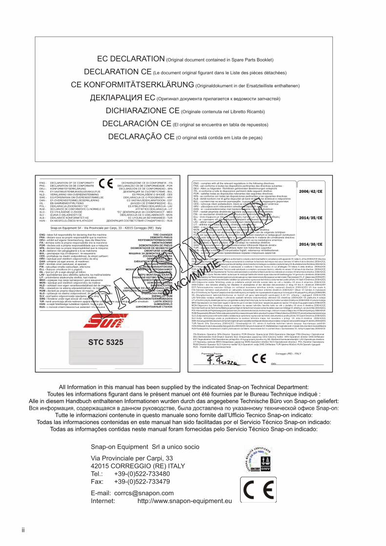
EC DECLARATION (Original document contained in Spare Parts Booklet)
DECLARATION CE (Le document original fi gurant dans le Liste des pièces détachées)
CE KONFORMITÄTSERKLÄRUNG (Originaldokument in der Ersatzteilliste enthaltenen)
ДЕКЛАРАЦИЯ EC (Оригинал документа прилагается к ведомости запчастей)
DICHIARAZIONE CE (Originale contenuta nel Libretto Ricambi)
DECLARACIÓN CE (El original se encuentra en tabla de repuestos)
DECLARAÇÃO CE (O original está contida em Lista de peças)
STC 5325
- ФАКСИМИЛЕ -
iii
DOCUMENTAZIONE DISPONIBILE
DOCUMENTAÇÃO DISPONÍVEL
DOCUMENTACIÓN DISPONIBLE
DOCUMENTATION AVAILABLEDOCUMENTATION DISPONIBLE
VERFÜGBARE DOKUMENTATIONДОСТУПНАЯ ДОКУМЕНТАЦИЯ
ABB. DESCRIPTION SIGLE DESCRIPTION KENN. BESCHREIBUNG
SIGLA DESCRIZIONESIGLA DESCRIPCIÓNSIGLA DESCRIÇÃO
:date of first publication
:date de la première édition
:Datum der Erstveröffentlichung
:data di prima pubblicazione
:fecha de la primera publicación
:data da primeira publicação
:дата первой публикации
:Product aid publicationTIRE CHANGER
:publication de support au produitDEMONTE PNEUS
:Zum Produkt gehörendes DokumentREIFENMONTIERGERÄT
:Пособие для работы с изделиемШИНОМОНТАЖНЫЙ СТАНОК
:Pubblicazione di supporto al prodottoSMONTAGOMME
:Documentação de apoio ao produtoMÁQUINA DE DESMONTAR PNEUS :publicación de soporte al producto
DESMONTA RUEDAS
Original language edition in: ITALIAN
Langue d’origine de la publication: ITALIEN
Originalausgabe in: ITALIENISCH
Edizione di lingua originale in: ITALIANO
Edición original en idioma: ITALIANO
Edição original em: ITALIANO
язык оригинального издания: АНГЛИЙСКИЙ
NOTES REGARDING DOCUMENTATION - ENG
NOTES SUR LA DOCUMENTATION - FRA
ANMERKUNGEN ZUR DOKUMENTATION - DEU
NOTE SULLA DOCUMENTAZIONE - ITA
NOTAS SOBRE A DOCUMENTAÇÃO - POR
NOTAS SOBRE LA DOCUMENTACIÓN - SPA
DICHIARAZIONE CEEC DECLARACIÓN CE
DECLARAÇÃO CE
Schema ElettricoWD Esquema Eléctrico
Esquema Eléctrico
Contenuto in SPIntegradas en SPConteúdos em SP
Contained in SPTeil der SP
Contenu dans SPСодержится в каталоге запчастей
EC DECLARATIONEC CE KONFORMITÄTSERKLÄRUNG
DECLARATION CEДЕКЛАРАЦИЯ ЕС
Wiring DiagramWD Schaltplan
Schéma électrique Схема электрических соединений
Operator’s Manual Manuel de l’Opérateur
OM Betriebsanleitung Руководство по эксплуатации
Spare Parts Booklet SP Liste des pièces détachées
Ersatzteilliste
Safety and Quick StartSécurité et Démarrage Rapide
OM Sicherheit und schneller StartБезопасность и быстрый запуск
OM Accessories Plan
Manuale OperatoreOM Manual de Operador
Manual do Operador
Libretto Ricambi SP tabla de repuestos
Lista de peças
Sicurezza e Avvio RapidoOM Segurança e Arranque Rápido
Seguridad y Arranque Rápido
OM Accessories Plan
05 / 2016
iv
UPDATING REPORTS
0
Safety rules are highlighted in grey.
Contents Page
1. General .............................................................iv2. Installation and connection .............................. 123. Bead breaking .................................................. 184. Clamping wheels .............................................. 205. Adjusting the mounting/demounting tool .......... 226. Demounting and mounting basics .................... 247. Demounting a tyre ............................................ 268. Mounting a tyre ................................................ 289. Infl ating a tyre ................................................. 3010. Maintenance ..................................................... 3811. Technical specifi cations ................................. 4012. Disposing of the unit ........................................ 42
1. General
1.1 Tips for the reader
Special symbols are used in this manual to facilitate
reading and understanding of pictures and written
instructions:
� Bullets indicate where an action/operation is
required.
Arrow indicating important information.
Arrow showing the direction of a
movement.
1.2 Scope
This tyre changer is designed to demount and mount
tyres with a diameter of between 10 and 24”.
Tyres can only be infl ated on the machine up to 3.3
bars.
Tyres which require a higher pressure must be
infl ated in suitable infl ating devices (safety cage and
the like).
Clamping ranges for outer and inner clamping are:
Outer clamping 10 to 24” rim diameter
Inner clamping 12 to 24” rim diameter
Accessories A series of accessories are normally available for the
machine. All the accessories are listed in the attached
document (fi g. 0):
ACCESSORIES PLAN
Code: See Fig. 0
• Use the codes in the list for the purchase orders.
Revision A of May 2016
First document issue PCN: 16G0151
Cod.: EAZ0103G20A
5
10” 22”12” 24”
10” 22”12” 24”
Inhalt Seite
1. Allgemeines ..........................................................52. Aufstellen und Anschließen ...............................133. Abdrücken eines Reifens ...................................194. Aufspannen der Räder .......................................195. Einstellen des Montierkopfes .............................236. Grundsätzliche Hinweise zur Montage
und Demontage eines Reifens ..........................257. Demontieren eines Reifens ................................278. Montieren eines Reifens .....................................299. Füllen der Reifen ................................................3110. Wartung ............................................................3911. Technische Daten ............................................4112. Entsorgung ........................................................43
1. Allgemeines
1.1 Hinweise für den LeserIn dieser Betriebsanleitung verwendete Merkhilfen, die einleichteres Lesen und besseres Verstehen der Bilder und Texte ermglichen sollen:
� stehen für Aufforderung zum Handeln.
Pfeilform für Zeigehinweise
Pfeilform für Bewegungsrichtung
1.2 Einsatzbereich
Reifenmontiermaschine mit oder ohne System zum Wulsteindrücken für schlauchlose Reifen
Die Reifenmontiermaschine ist für den Einsatz als Vorrichtung zur Montage und Demontage und sowie zum Wulsteindrücken von PKW- und Motorradreifen auf Tiefbettfelgen mit folgenden Eigenschaften vorgesehen:
Außenspannung Felgendurchmesser bisInnenspannung Felgendurchmesser bis
Als Sonderzubehör sind unter anderem Spannklauen zum Aufspannen von Felgen der Durchmesser 8”, Spannklauen zum Aufspannen von Motorradrädern der 15” bis 23” Felgendurchmesser lieferbar.
Zubehör Für die Maschine steht normalerweise eine Reihe von Zubehörteilen zur Verfügung. Das gesamte Zubehör ist in dem beiliegenden Dokument aufgelistet (Abb. 0):
ACCESSORIES PLAN (Zubehörplan), Codenummer: siehe Abb. 0
In dem Dokument fi nden Sie:- Zubehör, das mit der Maschine mitgeliefert wird: „S”.- Zubehör, das auf Bestellung erhältlich ist: „O”.- Zubehör, das für das betreffende Modell nicht anwendbar ist: „-”.
• Verwenden Sie zur Bestellung die Codenummern ausder Liste.
Mit Raster unterlegte Texte sind Sicherheitshinweise.
Table des matières Page
1. Généralités .........................................................52. Installation et raccordement .............................133. Décollage d’un pneu .........................................194. Serrage des roues ............................................195. Réglage de la tête de montage ........................236. Règles fondamentales de démontage / montage ...257. Démontage d’un pneu ......................................278. Montage d’un pneu ...........................................299. Gonfl age d’un pneu ..........................................3110. Entretien ...........................................................3911. Données techniques .........................................4112. Vente .................................................................43
1. Généralités
1.1 Avis au lecteurDans ce manuel, des symboles spéciaux ont été utilisés dans le but de faciliter la lecture et la compréhension des illustrations et des instructions:
� invite à effectuer une activité ou une opération.
Ce fl èche indique: infos importantes.
Ce fl èche indique: direction d’un mouvement.
1.2 Domaine d’application
Démonte-pneus, avec ou sans système Tubeless
Le démonte-pneus est destiné à être utilisé en tant que dispositif pour le montage, le démontage et l’enjantage talons de pneus pour des V.L. et motos montés sur jantes à base creuse avec les caractéristiques suivantes:
Serrage jante extérieur de à Serrage jante intérieur de à
Les accessoires disponibles sur demande, sont, entre autres, les mors de serrage pour jantes de diamètre de 8”, les mors de serrage pour roues de moto avec jantes comprises entre 15” et 23” de diamètre.
AccessoiresUne série d’accessoires sont normalement disponibles avec la machine. Tous les accessoires sont mentionnés dans le document ci-joint (fi g. 0) :
ACCESSORIES PLAN (Plan des accessoires) Code: voir Fig. 0
Dans le document fi gurent :- Accessoires fournis avec la machine; “S”.- Accessoires disponibles sur demande; “O”.- Accessoires non applicables au modèle consulté; “-”.
• Pour les commandes, prière d’utiliser les codesmentionnés dans la liste.
Les consignes de sécurité sont écrites sur fond gris.
6
1.3 General safety rules
Only properly trained and authorized personnel shall be allowed to operate the tyre changer.
Unauthorized changes and modifi cations to the machine relieve the manufacturer from any liability for damages and injuries that might result therefrom and cancel the EC Declaration given.
The machine must not be used except for the scope of application and in the way specifi ed in this manual.
When fi tting tyres on rims, make sure they fi t properly in size (identical nominal diameter); this means for example no tyres of nominal size in mm on rims of nominal size in inches and vice versa.
Always observe the applicable national guidelines when demounting, mounting or infl ating tyres (eg WdK Guidelines;
Wirtschaftsverband der deutschen Kautschukindustrie).
If troubles occur during operation of the machine, disconnect the machine from all energy supplies prior to remedy of the trouble.
In general any work on the electrical system such as fi tting of a plug or changing of connections, if necessary, must be carried out by a qualifi ed electrician in line with relevant national standards and the regulations of the local power station.
In general, it should be noted that working with technical equipment may involve unforeseen residual risks. Therefore, various self-explanatory warning labels (yellow/black triangle) are fi tted on the tyre changer.
These warning labels warn the operator against residual risks, calling for his special attention so as to prevent any injuries, accidents or damage.
In general the operator should eliminate these risks in advance by proper and wise behaviour.
In this, the following special points should be observed:
• Always use suitable and proper equipment andtools.
• Wear suitable protective clothing and usesuitable protection (e.g. safety goggles, earplugs, safety boots etc.).
• Strictly follow the instructions, notes andtechnical data of the machine manufacturer ormanufacturer of the product to be handled.
For further safety rules to be observed, please refer to the individual chapters.
7
1.3 Allgemeine Sicherheitshinweise
Reifenmontiermaschinen dürfen nur von befugtem und angemessen ausgebildetem Fachpersonal betrieben werden.Jede Art von Umbauten und/oder Veränderungen an der Maschine, die nicht vorher vom Hersteller genehmigt wurde, enthebt den Hersteller von der Haftung für Schäden und/oder Verletzungen, die durch solche Umbauten bzw. Veränderungen entstehen, und setzt die Zulassung für die Maschine, die zusammen mit der CE-Konformitätserklärung ergeht, außer Kraft.Die Maschinen dürfen ausschließlich entsprechend der bestimmungsgemäßen Verwendung und nach den Vorgehen, die in dieser Betriebsanleitung beschrieben sind, verwendet werden. Vor der Montage ist strikt darauf zu achten, dass Reifen und Felge zueinander passen und miteinander montierbar sind (übereinstimmende Maßangaben und der Nenndurchmesser muss gleich sein), das bedeutet z.B. dass Reifen, deren Nennmaße in mm angegeben sind, nicht an Felgen angepasst werden dürfen, deren Nennmaße in Zoll angegeben sind, und auch nicht umgekehrt.Bei der Demontage, der Montage oder dem Füllen von Reifen sind grundsätzlich die entsprechenden Vorschriften zu beachten, die in dem Anwendungsland gelten (z.B. die WdK-Leitlinien (Wirtschaftsverband der deutschen Kautschukindustrie). Treten während des Betriebs bzw. während des Arbeitsablaufs Störungen auf, sind sofort die Energieversorgungen der Maschine abzuschalten, bevor man irgend etwas anderes unternimmt.Generell dürfen sämtliche Arbeiten an der Stromanlage, wie z.B. der Anschluss eines Steckers oder das Auswechseln von Kabeln, nur von Elektrofachkräften unter Berücksichtigung der Vorschriften des jeweiligen Landes und der in dem jeweiligen Werk geltenden Regelungen vorgenommen werden. Bitte denken Sie daran, dass bei Arbeiten an technischen Geräten immer eine nicht vorhersehbare Restgefahr (Restrisiko) verbleibt; daher sind an der Reifenmontiermaschine verschiedene selbsterklärende Warnhinweise (gelb/schwarze Dreiecke) angebracht. Diese Aufkleber sollen den Benutzer auf Teile aufmerksam machen, bei denen eine solche Restgefahr vorliegt, damit mögliche Schäden, Unfälle und Verletzungen vermieden werden können.Generell sollte der Bediener solche Restgefahren durch vorbeugende Maßnahmen und ein sachgerechtes und umsichtiges Verhalten vermeiden. Hierbei sind besonders folgende Vorschriften zu beachten:• Verwenden Sie immer geeignete Geräte und
Instrumente.• Tragen Sie die Schutzkleidung und verwenden Sie
jeden nötigen weiteren Schutz (wie z.B. Schutzbrille, Gehörschutz, Sicherheitsschuhe usw.).
• Halten Sie sich genau an die Anleitung, dieHinweise und die technischen Daten des Herstellers der Maschine bzw. des verwendeten Produkts.
Für die weiteren Sicherheitsvorschriften, die beachtet werden müssen, wird auf die entsprechenden Kapitel verwiesen.
Consignes de sécurité générales 1.3
L’emploi de l’appareil est consenti exclusivement au.personnel expressément formé et autorisé Toute modification ou variation de l’appareil sans l’autorisation préalable du constructeur soulève ce dernier de toute responsabilité en cas de dommages matériels et personnels et rend nulle l’homologation délivrée par la.déclaration CE L’appareil doit être utilisé exclusivement pour l’usage pour lequel il a été fabriqué et conformément aux instructions.contenues dans ce manuel Au cours du montage, vérifier attentivement si le pneu et la jante présentent exactement les mêmes dimensions et s’ils peuvent être montés ensemble (dimensions indiquées dans la même unité de mesure, soit en mm, soit en.(.pouces etc Au cours du démontage montage ou gonflage des pneus, respecter d’une manière générale les lignes guides de la chambre professionnelle allemande de l’industrie du pneu (Lignes directrices WdK, par exemple; Wirtschaftsverband
.(der deutschen Kautschukindustrie
En cas de défaut au cours du fonctionnement, avant de rechercher un possible remède, couper.l’alimentation en énergie électrique de l’appareil Toutes les interventions sur l’équipement électrique doivent être effectuées par un électricien expert en conformité avec la réglementation en vigueur dans le.pays où l’appareil est utilisé En général, au cours des interventions d’installation, entretien et réparation, il est également nécessaire de respecter la réglementation en matière de prévention.des accidents du travail en vigueur Etant donné que l’emploi d’un appareillage technique comporte toujours un risque résiduel imprévisible, le constructeur a apposé des étiquettes avec un signal.de danger (triangle jaune/noir) sur le démonte-pneus Ces étiquettes de sécurité avertissent l’opérateur d’un possible risque résiduel et attirent son attention pour éviter le risque d’accidents sur le travail et/ou.dommages au produit à usiner L’opérateur doit éviter de tels risques en adoptant un.comportement avisé et prudent A ce titre, il convient de respecter les consignes:suivantes
Utiliser exclusivement les outils et les appareils •.appropriés
Porter les équipements de protection individuelle •
appropriés (ex.: des lunettes de protection, des.(bouchons d’oreilles, des chaussures de travail
Respecter les consignes, les instructions et les •
caractéristiques techniques de l’appareil et/ou du.fabricant du produit D’autres consignes de sécurité plus spécifiques sont.reportées plus loin
8
1.4 Description of operation
Clamping of the rim, tilting of the machine post and locking of the mounting head in its working position are effected pneumatically.
The four-jaw chuck is driven by means of an electric motor via V-belt and worm gear.
operation:Maximum speed for a given stall torque.
Control of machine operations is by means of a pedals which are arranged on a control unit.
Locking of the mounting head in its working position is accomplished pneumatically via a manually operated control valve incorporated in the locking lever on the mounting arm.
For clamping and unclamping of the wheel the entire machine post with mounting arm and head can be tilted to the rear without conditioning the working position. This means wheels of identical size can be handled successively without the need for repeated readjustment of the mounting head. The machine post is only tilted back to its working position on the rim fl ange.
A pneumatic tyre bead breaker for demounting tyres fi tting tightly to the rim is incorporated in the machine and is part of the standard equipment.
A manual tyre infl ator is also part of the equipment.
Upon special request the machine can be provided with a jet tyre infl ating system. For its operation and use see chapter “Infl ating the tyres”.
Basic version -Tubeless wheels system version
The Basic version includes the tyre changer with at the Turntable and with bead breaker that can be extended. The operation and use of the tyre changer is identical for versions with or without the Tubeless wheels device. The only difference for the Tubeless version is the presence of a bead seating for tubeless tyres which produces a powerful air jet towards the tyre chamber, close to the contact area between the tyre and the rim.
For fi tting, operation and use of the tubeless bead seating system see chapter “Infl ating a tyre”.
Stop button:When pressing the Stop button the machine stops thewheel support rotation.
CAUTION: WE RECOMMEND SWITCHING OFF THE UNIT AT THE END OF EACH DAY.
“ PRO speed ”
PRO speed
9
1.4 Funktionsbeschreibung
Die Felgenspannung, die Kippbewegung der Montiersäule sowie die Arretierung des Montierkopfes in seiner Arbeitsposition erfolgen pneumatisch. Der Spannteller, in dem die vier Spannklauen geführt sind, wird durch einen Elektromotor über Keilriemen und Schneckengetriebe angetrieben.
FunktionMaximale Drehzahl bei vorgegeben Widerstandsmoment.
Über Schaltpedale, die zu einer Betätigungseinheit zusammengefasst sind, werden die verschiedenen Arbeitsbewegungen der Maschine gesteuert.Der Montierkopf wird in seiner korrekten Arbeitsposition zur Felge pneumatisch über ein handbetätigtes Steuerventil arretiert, das im Führungsgriff am Montierarm eingebaut ist.Zum Aufspannen und Abspannen des Rades kann die gesamte Montiersäule mit Montierarm und Montierkopf nach hinten gekippt werden, ohne dass die Arbeitsposition verstellt wird. Dadurch erübrigt sich bei der Bearbeitung mehrerer gleicher Räder hintereinander das wiederholte Neueinstellen des Montierkopfes. Die Montiersäule wird lediglich wieder in ihre Arbeitsposition an das Felgenhorn herangekippt.Eine pneumatische Reifenabdrückeinrichtung zum Abdrücken fest auf der Felge sitzender Reifen ist in die Maschine integriert und gehört zum Lieferumfang.Zum Befüllen des Reifens ist ein Handfüllmesser Bestandteil des Lieferumfanges.Auf Wunsch kann die Maschine mit einer jet Reifenfüllanlage ausgerüstet bzw. nachgerüstet werden. Die Funktion und Handhabung dieser Reifenfüllanlage ist im Kapitel 9. Füllen der Reifen beschrieben.
Basisversion - Tubeless-BasisversionDie Basisversion beinhaltet die Reifenmontiermaschine mit an der 22” Turntable und mit Abdrücker die erweitert werden kann. Die Funktionsweise und die Anwendung der Reifenmontiermaschine sind bei der Version mit und bei der Version ohne Tubeless-Vorrichtung gleich. Bei der Tubeless-Version liegt der einzige Unterschied darin, dass sie ein System zum Wulsteindrücken bei schlauchlosen Reifen besitzt, das im Kontaktbereich zwischen Reifen und Felge einen starken Luftstoß in Richtung des Schlauchs ausstößt.Was das Montieren, die Funktionsweise und die Anwendung der Vorrichtung zum Wulsteindrücken bei schlauchlosen Reifen betrifft, wird auf das Kapitel „Füllen eines Reifens” verwiesen.
Stopp-Taste:Auf das Drücken der Stopp-Taste schaltet die Maschineden Stopp der Rotation des Radhalters.
ACHTUNG: ES WIRD EMPFOHLEN, DAS GERÄTAM ENDE DES ARBEITSTAGS AUSZUSCHALTEN.
1.4 Description du fonctionnement
Le serrage de la jante, le basculement du montant de la machine et le blocage de la tête de montage dans sa position de travail se font par actionnement pneumatique.
Le mandrin à quatre mors autocentrants est entraîné par un moteur électrique au moyen d’une courroie trapézoïdale et d’un engrenage à vis sans fi n.
Fonction Vitesse max pour un couple résistant donné.
La commande des mouvements de la machine se fait par des pédales regroupées en une unité de commande.
Le blocage de la tête de montage dans sa position de travail se fait par voie pneumatique au moyen d’une vanne à commande manuelle intégrée dans le levier de blocage du bras de montage.
Pour le serrage et desserrage de la roue, le montant de la machine avec le bras et la tête de montage peut être basculé en arrière sans déréglage de la position de travail. Par conséquent, des roues de dimensions identiques peuvent être manipulées sans répéter le réglage de la tête de montage. Il suffi t donc de faire basculer le montant de la machine dans sa position de travail sur le rebord de la jante.
Un dispositif pneumatique de décollage des pneus conçu pour décoller les pneus à forte assise sur la jante est intégré dans la machine et fait partie de l’équipement standard.
Un gonfl eur-mesureur manuel fait également partie intégrante de l’équipement standard.
Sur demande, la machine peut être équipée d’un système de gonfl age “jet”. Pour son fonctionnement et son emploi voir chapitre “Gonfl age des pneus”.
Version base - Version avec système Tubeless
La version de base comprend une vitesse intelligente à le table tournante et comprend une bras détalonneur prolongable.
Le fonctionnement et l’utilisation du démonte-pneus est identique pour les versions avec et sans dispositif pour Tubeless. La seule différence pour la version Tubeless est la présence d’un système d’enjantage pour pneus Tubeless, qui produit un puissant jet d’air dans la direction de la chambre du pneu, à proximité de la zone de contact entre le pneu et la jante.Pour le montage, le fonctionnement et l’utilisation du dispositif d’enjantage tubeless, voir la rubrique “Gonfl age d’un pneu “.
Bouton d’arrêt:Si l’on appuie sur le bouton d’arrêt, la machine exécutela fonction d’arrêt de la rotation du support roue.
ATTENTION: IL EST CONSEILLÉ D’ÉTEINDRE LA MACHINE QUAND LA JOURNÉE DE TRAVAIL EST TERMINÉE.
“PRO speed ”“ PRO speed ”
PRO speed: PRO speed:
10
1
2
3
5
7
9
1011 12
13
6
1
8
14
4
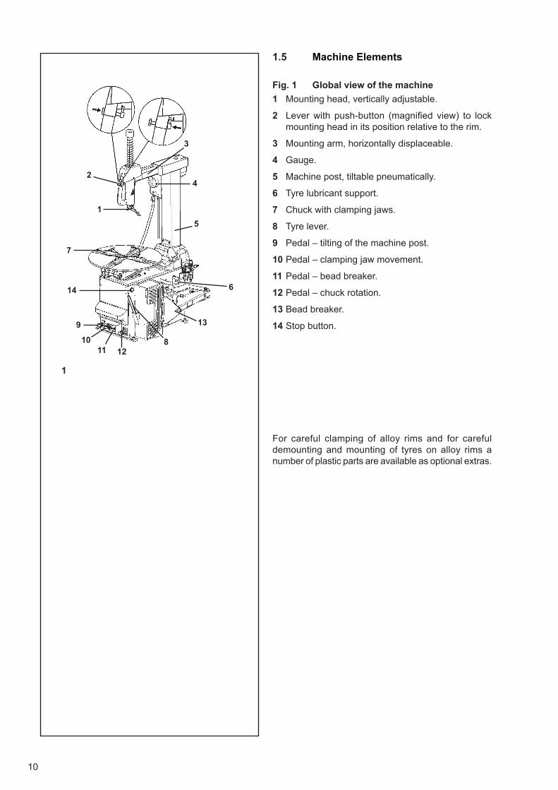
1.5 Machine Elements
Fig. 1 Global view of the machine
1 Mounting head, vertically adjustable.
2 Lever with push-button (magnifi ed view) to lock mounting head in its position relative to the rim.
3 Mounting arm, horizontally displaceable.
4 Gauge.
5 Machine post, tiltable pneumatically.
6 Tyre lubricant support.
7 Chuck with clamping jaws.
8 Tyre lever.
9 Pedal – tilting of the machine post.
10 Pedal – clamping jaw movement.
11 Pedal – bead breaker.
12 Pedal – chuck rotation.
13 Bead breaker.
14 Stop button.
For careful clamping of alloy rims and for careful demounting and mounting of tyres on alloy rims a number of plastic parts are available as optional extras.
11
1.5 Maschinenelemente
Abb. 1 Maschinenübersicht mit Funktionselementen
1 Montierkopf, höhenverstellbar.
2 Führungsgriff mit Drucktaster (vergrößerte Darstellung)zur Arretierung des Montierkopfes an der Felge.
3 Montierarm, horizontal verschiebbar.
4 Druckanzeige.
5 Montiersäule, pneumatisch kippbar.
6 Halter für Montagepastengefäß.
7 Spannteller mit Spannklauen.
8 Montiereisen.
9 Schaltpedal – Kippbewegung der Montiersäule.
10 Schaltpedal – Spannklauenbewegung.
11 Schaltpedal – Abdrückeinrichtung.
12 Schaltpedal – Drehbewegung des Spanntellers
13 Reifenabdrücker.
14 Stopp-Taste.
Als Sonderzubehör stehen zum schonenden Spannen von Leichtmetal l felgen sowie zum schonenden Demontieren und Montieren von Reifen auf Leichtmetallfelgen eine ganze Reihe von Kunststoffteilen zur Verfügung.
1.5 Eléments de la machine
Fig. 1 Vue de la machine et des éléments fonctionnels
1 Tête de montage, réglable en hauteur.
2 Levier avec bouton-poussoir (vue agrandie) pour bloquerla tête de montage dans sa position de travail.
3 Bras de montage, à déplacement horizontal.
4 Manomètre.
5 Montant de machine à basculement pneumatique.
6 Porte-réservoir lubrifi ant du pneu.
7 Mandrin avec mors de serrage.
8 Levier de montage.
9 Pédale – basculement du montant de la machine.
10 Pédale – réglage mors de serrage.
11 Pédale – décolleur.
12 Pédale – rotation mandrin
13 Décolleur.
14 Bouton d’arrêt.
Pour permettre un serrage de jantes en alliage léger, ainsi que le démontage et le montage de pneus sur les jantes en alliage léger, sans risque d’endommagement, de nombreuses pièces en matière plastique sont disponibles en option.
12
2
2a
1b
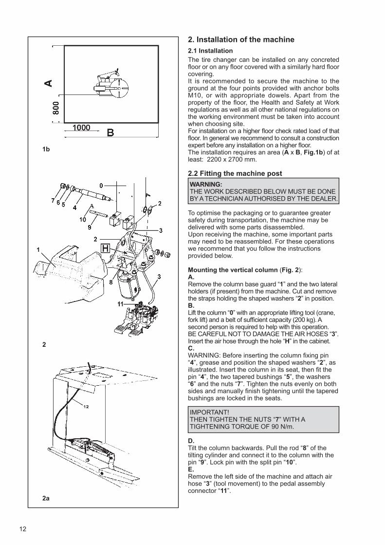
2. Installation of the machine
2.1 Installation
The tire changer can be installed on any concreted fl oor or on any fl oor covered with a similarly hard fl oor covering. It is recommended to secure the machine to the ground at the four points provided with anchor bolts M10, or with appropriate dowels. Apart from the property of the fl oor, the Health and Safety at Work regulations as well as all other national regulations on the working environment must be taken into account when choosing site. For installation on a higher fl oor check rated load of that fl oor. In general we recommend to consult a construction expert before any installation on a higher fl oor. The installation requires an area (A x B, Fig.1b) of at least: 2200 x 2700 mm.
2.2 Fitting the machine post
WARNING: THE WORK DESCRIBED BELOW MUST BE DONE BY A TECHNICIAN AUTHORISED BY THE DEALER.
To optimise the packaging or to guarantee greater safety during transportation, the machine may be delivered with some parts disassembled.Upon receiving the machine, some important parts may need to be reassembled. For these operations we recommend that you follow the instructions provided below.
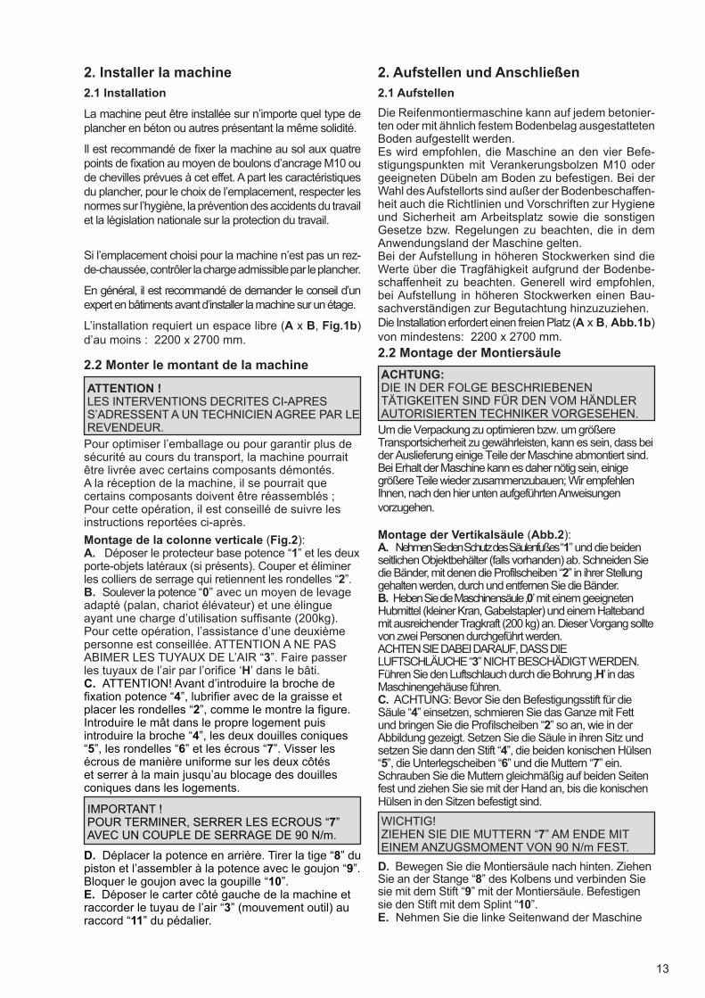
Mounting the vertical column (Fig. 2):A. Remove the column base guard “1” and the two lateral holders (if present) from the machine. Cut and remove the straps holding the shaped washers “2” in position.B.Lift the column “0” with an appropriate lifting tool (crane, fork lift) and a belt of suffi cient capacity (200 kg). A second person is required to help with this operation. BE CAREFUL NOT TO DAMAGE THE AIR HOSES “3”. Insert the air hose through the hole “H” in the cabinet.C.WARNING: Before inserting the column fi xing pin “4”, grease and position the shaped washers “2”, as illustrated. Insert the column in its seat, then fi t the pin “4”, the two tapered bushings “5”, the washers “6” and the nuts “7”. Tighten the nuts evenly on both sides and manually fi nish tightening until the tapered bushings are locked in the seats.
IMPORTANT!THEN TIGHTEN THE NUTS “7” WITH A TIGHTENING TORQUE OF 90 N/m.
D.Tilt the column backwards. Pull the rod “8” of the tilting cylinder and connect it to the column with the pin “9”. Lock pin with the split pin “10”.E.Remove the left side of the machine and attach air hose “3” (tool movement) to the pedal assembly connector “11”.
13
2. Aufstellen und Anschließen
2.1 Aufstellen
Die Reifenmontiermaschine kann auf jedem betonier-ten oder mit ähnlich festem Bodenbelag ausgestatteten Boden aufgestellt werden.Es wird empfohlen, die Maschine an den vier Befe-stigungspunkten mit Verankerungsbolzen M10 oder geeigneten Dübeln am Boden zu befestigen. Bei der Wahl des Aufstellorts sind außer der Bodenbeschaffen-heit auch die Richtlinien und Vorschriften zur Hygiene und Sicherheit am Arbeitsplatz sowie die sonstigen Gesetze bzw. Regelungen zu beachten, die in dem Anwendungsland der Maschine gelten. Bei der Aufstellung in höheren Stockwerken sind die Werte über die Tragfähigkeit aufgrund der Bodenbe-schaffenheit zu beachten. Generell wird empfohlen, bei Aufstellung in höheren Stockwerken einen Bau-sachverständigen zur Begutachtung hinzuzuziehen. Die Installation erfordert einen freien Platz (A x B, Abb.1b) von mindestens: 2200 x 2700 mm.
2.2 Montage der Montiersäule
ACHTUNG: DIE IN DER FOLGE BESCHRIEBENEN TÄTIGKEITEN SIND FÜR DEN VOM HÄNDLER AUTORISIERTEN TECHNIKER VORGESEHEN.
Um die Verpackung zu optimieren bzw. um größere Transportsicherheit zu gewährleisten, kann es sein, dass bei der Auslieferung einige Teile der Maschine abmontiert sind.Bei Erhalt der Maschine kann es daher nötig sein, einige größere Teile wieder zusammenzubauen; Wir empfehlen Ihnen, nach den hier unten aufgeführten Anweisungen vorzugehen.
Montage der Vertikalsäule (Abb.2):A. Nehmen Sie den Schutz des Säulenfußes “1” und die beiden seitlichen Objektbehälter (falls vorhanden) ab. Schneiden Sie die Bänder, mit denen die Profilscheiben “2” in ihrer Stellung gehalten werden, durch und entfernen Sie die Bänder.B. Heben Sie die Maschinensäule ‚0’ mit einem geeigneten Hubmittel (kleiner Kran, Gabelstapler) und einem Halteband mit ausreichender Tragkraft (200 kg) an. Dieser Vorgang sollte von zwei Personen durchgeführt werden.ACHTEN SIE DABEI DARAUF, DASS DIE LUFTSCHLÄUCHE “3” NICHT BESCHÄDIGT WERDEN. Führen Sie den Luftschlauch durch die Bohrung ‚H’ in das Maschinengehäuse führen.C. ACHTUNG: Bevor Sie den Befestigungsstift für die Säule “4” einsetzen, schmieren Sie das Ganze mit Fett und bringen Sie die Profi lscheiben “2” so an, wie in der Abbildung gezeigt. Setzen Sie die Säule in ihren Sitz und setzen Sie dann den Stift “4”, die beiden konischen Hülsen “5”, die Unterlegscheiben “6” und die Muttern “7” ein. Schrauben Sie die Muttern gleichmäßig auf beiden Seiten fest und ziehen Sie sie mit der Hand an, bis die konischen Hülsen in den Sitzen befestigt sind.
WICHTIG!ZIEHEN SIE DIE MUTTERN “7” AM ENDE MIT EINEM ANZUGSMOMENT VON 90 N/m FEST.
D. Bewegen Sie die Montiersäule nach hinten. Ziehen Sie an der Stange “8” des Kolbens und verbinden Sie sie mit dem Stift “9” mit der Montiersäule. Befestigen sie den Stift mit dem Splint “10”.E. Nehmen Sie die linke Seitenwand der Maschine
2. Installer la machine
2.1 Installation
La machine peut être installée sur n’importe quel type de plancher en béton ou autres présentant la même solidité.
Il est recommandé de fi xer la machine au sol aux quatre points de fi xation au moyen de boulons d’ancrage M10 ou de chevilles prévues à cet effet. A part les caractéristiques du plancher, pour le choix de l’emplacement, respecter les normes sur l’hygiène, la prévention des accidents du travail et la législation nationale sur la protection du travail.
Si l’emplacement choisi pour la machine n’est pas un rez-de-chaussée, contrôler la charge admissible par le plancher.
En général, il est recommandé de demander le conseil d’un expert en bâtiments avant d’installer la machine sur un étage.
L’installation requiert un espace libre (A x B, Fig.1b) d’au moins : 2200 x 2700 mm.
2.2 Monter le montant de la machine
ATTENTION ! LES INTERVENTIONS DECRITES CI-APRES S’ADRESSENT A UN TECHNICIEN AGREE PAR LE REVENDEUR.
Pour optimiser l’emballage ou pour garantir plus de sécurité au cours du transport, la machine pourrait être livrée avec certains composants démontés.A la réception de la machine, il se pourrait que certains composants doivent être réassemblés ; Pour cette opération, il est conseillé de suivre les instructions reportées ci-après.
Montage de la colonne verticale (Fig.2):A. Déposer le protecteur base potence “1” et les deux porte-objets latéraux (si présents). Couper et éliminer les colliers de serrage qui retiennent les rondelles “2”.B. Soulever la potence “0” avec un moyen de levage adapté (palan, chariot élévateur) et une élingue ayant une charge d’utilisation suffi sante (200kg). Pour cette opération, l’assistance d’une deuxième personne est conseillée. ATTENTION A NE PAS ABIMER LES TUYAUX DE L’AIR “3”. Faire passer les tuyaux de l’air par l’orifi ce ‘H’ dans le bâti.C. ATTENTION! Avant d’introduire la broche de fi xation potence “4”, lubrifi er avec de la graisse et placer les rondelles “2”, comme le montre la fi gure. Introduire le mât dans le propre logement puis introduire la broche “4”, les deux douilles coniques “5”, les rondelles “6” et les écrous “7”. Visser les écrous de manière uniforme sur les deux côtés et serrer à la main jusqu’au blocage des douilles coniques dans les logements.
IMPORTANT !POUR TERMINER, SERRER LES ECROUS “7” AVEC UN COUPLE DE SERRAGE DE 90 N/m.
D. Déplacer la potence en arrière. Tirer la tige “8” du piston et l’assembler à la potence avec le goujon “9”. Bloquer le goujon avec la goupille “10”.E. Déposer le carter côté gauche de la machine et raccorder le tuyau de l’air “3” (mouvement outil) au raccord “11” du pédalier.
14
3
4
5
1
2
3
6
5
7
4
5
For models with the infl ating device built into the column also:F.Connect the diameter 8 hose (12, Fig.2a), from the column to the infl ating pedal tap as illustrated.
Note: For hose connections, see the pneumatic diagrams supplied in the Spare Parts Manual. G.Refi t the column base guard “1” and all of the parts previously removed.H.Secure the tyre changer to the fl oor.
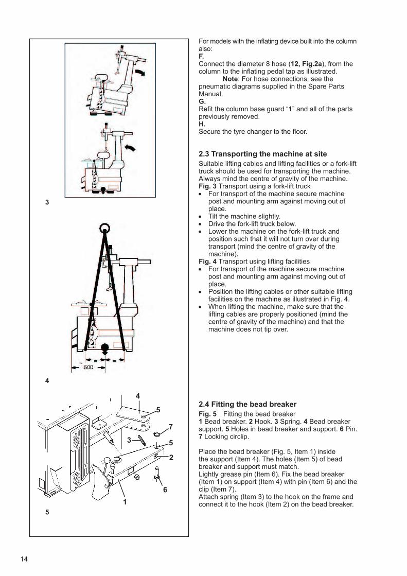
2.3 Transporting the machine at site Suitable lifting cables and lifting facilities or a fork-lift truck should be used for transporting the machine. Always mind the centre of gravity of the machine. Fig. 3 Transport using a fork-lift truck • For transport of the machine secure machine
post and mounting arm against moving out of place.
• Tilt the machine slightly.• Drive the fork-lift truck below.• Lower the machine on the fork-lift truck and
position such that it will not turn over duringtransport (mind the centre of gravity of themachine).
Fig. 4 Transport using lifting facilities • For transport of the machine secure machine
post and mounting arm against moving out of place.
• Position the lifting cables or other suitable liftingfacilities on the machine as illustrated in Fig. 4.
• When lifting the machine, make sure that thelifting cables are properly positioned (mind the centre of gravity of the machine) and that the machine does not tip over.
2.4 Fitting the bead breaker Fig. 5 Fitting the bead breaker 1 Bead breaker. 2 Hook. 3 Spring. 4 Bead breaker support. 5 Holes in bead breaker and support. 6 Pin. 7 Locking circlip.
Place the bead breaker (Fig. 5, Item 1) inside the support (Item 4). The holes (Item 5) of bead breaker and support must match. Lightly grease pin (Item 6). Fix the bead breaker (Item 1) on support (Item 4) with pin (Item 6) and the clip (Item 7). Attach spring (Item 3) to the hook on the frame and connect it to the hook (Item 2) on the bead breaker.
15
ab und schließen Sie den Luftschlauch “3” (Werkzeugbewegung) an den Anschluss “11” der Pedalsteuerung an.
Bei Modellen, bei denen die Reifenfüllvorrichtung in die Montiersäule integriert ist, müssen Sie außerdem Folgendes tun:
F. Schließen Sie den Schlauch mit Durchmesser 8 (12, Abb. 2a), der von der Montiersäule kommt, an den Hahn des Füllventils an, wie in der Abbildung gezeigt.
Anmerkung: Für den Anschluss der Schläuche beziehen Sie sich bitte auf die Druckluftpläne, die im Heft der Ersatzteile enthalten sind.
G. Montieren Sie den Schutz des Säulenfußes “1” und sämtliche Teile, die vorher ausgebaut wurden, wieder.H. Befestigen Sie die Reifenmontiermaschine.
2.3 Transport der Maschine an den Aufstellungsort
Transportieren Sie die Maschine mit den geeigneten Seilen und Hubmitteln oder mit einem Gabelstapler. Halten Sie die Maschine dabei immer im Gleichgewicht.
Abb. 3 Transportier mit einem Gabelstapler
• Befestigen Sie die Maschinensäule und denMontagearm während des Transports so, dasssie sich nicht aus ihrer Lage verschieben können.
• Kippen Sie die Maschine leicht.
• Führen Sie die Gabeln des Gabelstaplers unterdie Maschine ein.
• Stellen Sie die Maschine ganz auf den Gabel-stapler und positionieren Sie sie so, dass siewährend des Transports nicht umfallen kann (dieMaschine muss immer im Gleichgewicht gehaltenwerden).
Abb. 4 Transport mit Hubmitteln
• Befestigen Sie die Maschinensäule und denMontagearm während des Transports so, dasssie sich nicht aus ihrer Lage verschieben können.
• Legen Sie die Hubseile bzw. sonstigen Vor-richtungen zum Anheben, die Sie eventuellverwenden, so, wie in der Abbildung 4 gezeigt.
• Stellen Sie beim Anheben der Maschine sicher,dass die Hubseile in der richtigen Lage sind (hal-ten Sie die Maschine immer im Gleichgewicht)und dass die Maschine nicht umkippt.
2.4 Montage der Abdrückvorrichtung
Abb 5 Montage der Abdrückvorrichtung
1 Abdrückvorrichtung. 2 Haken. 3 Feder. 4 Träger der Abdrückvorrichtung. 5 Bohrungen an der Abdrückvor-richtung und am Träger. 6 Zapfen. 7 Sicherungsring.
Stellen Sie die Abdrückvorrichtung (1, Abb. 5) in den Trä-ger (4). Die Bohrungen (5) an der Abdrückvorrichtungen müssen mit denen des Trägers übereinstimmen.Schmieren Sie den Zapfen (6) leicht. Befestigen Sie die Abdrückvorrichtung (1) mit dem Zapfen (6) und der Sicherungsring (7) am Träger (4). Befestigen Sie die Feder (3) an dem Haken, der sich am Rahmen befi ndet, und am Haken (2) der Abdrückvorrich-tung.
Les modèles avec dispositif de gonfl age intégré dans la potence, nécessitent aussi de:F. Raccorder le tuyau diamètre 8 (12, Fig.2a) qui arrive de la potence au robinet de la pédale de gonfl age, comme le montre la fi gure.
Nota bene: Pour le raccordement des tuyaux, voir les schémas pneumatiques fournis dans la notice Pièce de rechange.
G. Remonter le protecteur base potence “1” et tous les composants précédemment déposés.H. Fixer le démonte-pneu au sol.
2.3 Transporter la machine sur son emplacement
Transporter la machine avec les câbles et les moyens de levage prévus à cet effet ou avec un chariot élévateur à fourches. Veiller à toujours maintenir la charge équilibrée.
Fig. 3 Transporter avec un chariot élévateur à fourches
• Au cours du transport, fi xer le montant de lamachine et le bras de montage de manière à lesimmobiliser dans leur position.
• Renverser légèrement la machine.• Faire passer les fourches du chariot élévateur en
dessous de la machine.• Déposer la machine sur le chariot élévateur et
la placer de manière à ce qu’elle ne se renversepas pendant le transport (toujours maintenir lamachine bien équilibrée).
Fig. 4 Transporter avec des moyens de levage • Au cours du transport, fi xer le montant de la
machine et le bras de montage de manière à les immobiliser dans leur position.
• Positionner les câbles de levage et les autresmoyens de levage le cas échéant utilisés sur la machine comme il est illustré Fig. 4.
• Au cours du levage de la machine, s’assurer queles câbles de levage sont placés correctement (maintenir la machine bien équilibrée) et que la machine ne sera pas basculer.
2.4 Monter l’outil détalonneur
Fig. 5 Monter l’outil détalonneur
1 Outil détalonneur. 2 Crochet. 3 Ressort. 4 Support outil détalonneur. 5 Perçages outil détalonneur et support. 6 Broche. 7 Anneau élastique.
Mettre l’outil détalonneur (1, Fig. 5) dans le support (4). Les orifi ces (5) de l’outil détalonneur doivent correspondre avec ceux du support.
Lubrifi er légèrement la broche (6). Fixer l’outil détalonneur (1) sur le support (4) avec la broche (6) et le circlips (7).
Accrocher le ressort (3) au crochet qui se trouve sur le bâti et l’unir au crochet (2) de l’outil détalonneur.
16
16
Smart Speed
7
230 V, 1Ph, 50/60Hz, 16A
240 V, 1Ph, 50/60Hz, 16A
200 V, 1Ph, 50/60Hz, 20A
CE
UL
JA
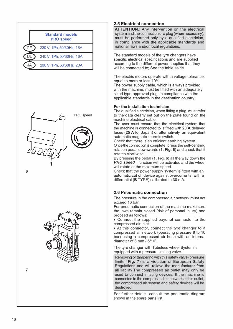
2.5 Electrical connection ATTENTION.: Any intervention on the electrical system and the connection of a plug (when necessary), must be performed only by a qualifi ed electrician, in compliance with the applicable standards and national laws and/or local regulations.
The standard models of the tyre changers have specifi c electrical specifi cations and are supplied according to the different power supplies that they will be connected to; See the table aside.
The electric motors operate with a voltage tolerance; equal to more or less 10%. The power supply cable, which is always provided with the machine, must be fi tted with an adequately sized type-approved plug, in compliance with the applicable standards in the destination country.
For the installation technician The qualifi ed electrician, when fi tting a plug, must refer to the data clearly set out on the plate found on the machine electrical cable.The user must ensure that the electrical system that the machine is connected to is fi tted with 20 A delayed fuses (25 A for Japan) or alternatively, an equivalent automatic magneto-thermic switch. Check that there is an effi cient earthing system.Once the connection is complete, press the self-centring rotation pedal downwards (1, Fig. 6) and check that it rotates clockwise. By pressing the pedal (1, Fig. 6) all the way down the function will be activated and the wheel will rotate at the maximum speed.Check that the power supply system is fi tted with an automatic cut off device against overcurrents, with a differential (B TYPE) calibrated to 30 mA.
2.6 Pneumatic connectionThe pressure in the compressed air network must not exceed 16 bar.For pneumatic connection of the machine make sure the jaws remain closed (risk of personal injury) and proceed as follows:• Connect the supplied bayonet connector to thecompressed air inlet.• At this connector, connect the tyre changer to acompressed air network (operating pressure 8 to 10 bar) using a compressed air hose with an internal diameter of 8 mm / 5/16”.
The tyre changer with Tubeless wheel System is equipped with a pressure limiting valve.
Removing or tampering with this safety valve (pressure limiter Fig. 7) is a violation of European Safety Regulations and will relieve the manufacturer from all liability.The compressed air outlet may only be used to connect infl ating devices. If the machine is connected to the compressed air network at this outlet, the compressed air system and safety devices will be destroyed.
For further details, consult the pneumatic diagram shown in the spare parts list.
PRO speed
Standard modelsPRO speed
PRO speed
17
2.5 Elektroanschluss ACHTUNG: Sämtliche Eingriffe an der elektrischen Anlage und den Anschluss eines Steckers (wenn erforderlich), dürfen ausschließlich von einem qualifi zierten Elektriker ausgeführt werden, unter Beachtung der von der nationalen Gesetzgebung bzw. den lokalen Verordnungen vorgesehenen Rechtsvorschriften.
Die Standardmodelle der Reifenmontiermaschinen haben spezifi sche elektrische Eigenschaften und werden je nach den verschiedenen Versorgungsnetzen, an die sie angeschlossen werden sollen, in folgenden Ausführungen geliefert; Siehe die Tabelle beiseite.Die Elektromotoren arbeiten mit einer Spannungstoleranz von etwa 10%. Das Kabel für den Netzanschluss, mit dem alle Maschinen ausgestattet sind, muss über einen zugelassenen Stecker mit passender Größe verfügen, gemäß der im Aufstellungsland geltenden Rechtsvorschriften.
Für den InstallateurSollte es erforderlich sein, dass der qualifizierte Elektriker einen Stecker montiert, muss er sich dabei an die eindeutig auf dem Schild am Anschlusskabel der Maschine angegebenen Daten halten.Wir empfehlen, bei der Vorbereitung der elektrischen Anlage, an die die Maschine angeschlossen werden soll, träge 20A-Sicherungen bzw. (25 A für Japan) einen gleichwertigen automatischen Schalter (Magnetschutzschalter) zu installieren. Außerdem muss eine funktionierende Erdungsanlage vorhanden sein.Sobald der Anschluss vorgenommen wurde, das Pedal (1, Abb. 6) für die Freigabe der Rotation des Zentrierfutters betätigenund prüfen, ob sich dieses im Uhrzeigersinn dreht. Wird das Pedal bis auf Anschlag gedrückt, wird die Funktion aktiviert und das Rad wird mit der maximalen Drehzahl drehen. Sicherstellen, dass die Versorgungsanlage mit einem auf 30mA geeichten automatischen Trennschalter (Typ B) ausgerüstet ist.
2.6 Pneumatischer AnschlussDer Druck im Druckluftnetz darf keinesfalls über 16 bar ansteigen. Um den Druckluftanschluss der Maschine herzustellen, müssen die Spannklauen geschlossen bleiben (Verletzungsgefahr).Wie folgt vorgehen:• Am Drucklufteingang den im Lieferumfang
enthaltenen Bajonett-Anschluss anbringen.• An diesem Anschluss die Maschine mit einem
Druckluftschlauch mit 8 mm / 5/16” lichter Weite an einDruckluftnetz mit Anschlussdruck 8 bis 10 bar anschließen.
Die Reifenmontiermaschine mit Tubeless-Version-System ist mit einem Druckbegrenzungsventil ausgestattet.
Das Sicherheitsventil (Druckbegrenzungsventil Abb. 7) ist in Europa gesetzlich vorgeschrieben und darf nicht verstellt oder entfernt werden. Der Hersteller haftet nicht für Schäden, die durch Verstellen oder Entfernen dieses Ventils entstehen. Den Druckluftausgang ausschließlich zum Anschließen von Reifenfüllgeräten verwenden. Wird die Maschine hier ans Druckluftnetz angeschlossen, werden Druckluftanlage und Sicherheitsvorrichtungen zerstört.
Der in der Ersatzteilliste abgebildete Pneumatikplan zeigt die Anschlusssituation.
2.5 Branchement électrique
ATTENTION! Toute intervention sur le système électrique et la connexion d’une fi che lorsque cela est nécessaire, doit être effectuée exclusivement par un électricien qualifi é, conformément à la réglementation en la matière et suivant les lois nationales et/ou les règlements locaux en vigueur.
Les modèles standards des démonte-pneus possèdent des caractéristiques électriques spécifiques et sont conçus en fonction des différents réseaux d’alimentation en énergie électrique auxquels ils sont susceptibles d’être branchés: Voir la table de côté.
Les moteurs électriques admettent une tolérance égale à plus ou moins 10% environ de la tension.Le câble de raccordement au réseau dont la machine est équipée, doit être muni d’une fi che homologuée, correctement dimensionnée, dans le respect des réglementations en vigueur dans le pays auquel la machine est destinée.
Pour le Technicien InstallateurL’électricien qualifi é, dans le cas où il serait amener à installer une fiche, doit se référer aux données clairement reportées sur la plaquette apposée sur le câble d’alimentation électrique de la machine.La mise en conformité du réseau électrique qui alimentera la machine est à la charge de l’utilisateur. Il est recommandé d’installer des fusibles lents de 20 A (25 Apour le Japon) ou un interrupteur automatique (magnétothermique) équivalent. Vérifi er s’il existe une mise à la terre et si elle fonctionne correctement.Le raccordement effectué, actionner vers le bas la pédale de commande de la rotation de l’autocentrant (1, Fig. 6) et vérifi er s’il tourne dans le sens horaire. En poussant la pédale à fond, la fonction sera activée et la roue tournera à la vitesse max.Contrôler si le réseau électrique qui alimentera la machine est muni d’un dispositif d’interruption automatique contre les surintensités avec un différentiel (B TYPE) réglé sur 30 mA.
2.6 Raccordement pneumatique
La pression dans le réseau d’air comprimé ne doit jamais dépasser 16 bars.Pour le raccordement pneumatique, les mors doivent rester fermés (risque d’accident). Procéder comme suit:• Brancher le raccord à baïonnette à l’entrée d’air comprimé.• A ce raccord, brancher la machine au réseau d’air
comprimé (pression de service conseillée 8 à 10 bars) enutilisant un tuyau d’un diamètre interne de 8 mm / 5/16».
Le démonte-pneus avec le système de roue sans chambre à air est équipé d’un limiteur de pression.
Le démontage ou la manipulation du limiteur de pression (Fig. 7) est une violation des normes européennes. Le constructeur décline toute responsabilité dans le cas de dommages attribuables à ces actes. N’utiliser la sortie d’air comprimé que pour le branchement des dispositifs de gonfl age. Si la machine est branchée au réseau d’air comprimé par cette sortie, le système d’air comprimé et les dispositifs de sécurité seront détruits.
Pour les détails, voir le plan pneumatique illustré dans la liste des pièces détachées.
PRO speedPRO speed
18
9
1
2
9b
3
10
1
2
4
3. Bead breaking
With the tyre changers a pneumatic tyre bead breaker is part of the standard equipment.
Please mind the special handling of Run-fl at tires, wheels with TD rims or rims having an asymmetric hump.
3.1 Bead breaking
Remove the valve insert of the wheel valve.
We would recommend to demount the tyre from the wide rim shoulder in the fi rst place.
Lean the defl ated wheel on the side against the special rubber pads provided at the machine housing.
NOTE: If the tire is over 13” (340 mm) wide, fi rst set the bead breaker in the “Wide” position as follow:
1) Pull up and hold pin (3, Fig. 9b), and pull the beadbreaker assembly in the “Wide” position.
2) Insert pin again (3, Fig. 9b) in its hole to lock thebead breaker in the new position.
Position the bead breaker blade (1, Fig. 9) on the outside of the tyre approximately 1 cm away from the edge of the rim using the adjustable handle for accurate positioning.
Depress pedal (2, Fig. 9). The blade moves in between tyre and rim. Release the pedal, continue to rotate the wheel and repeat the breaking procedure until the tyre has been unseated completely.
Proceed analogously with the second tyre bead.
In order to facilitate subsequent demounting of tyre and to preserve tyre and rim, it is most useful to apply a commercial lubricant on tyre and rim at the place where the bead breaking blade has just penetrated into the rim base. Never use other agents only supposed to lubricate!
4. Clamping the wheels
• Before clamping a wheel, release the mounting/demounting tool (1, Fig. 10), move the mounting/demounting tool to its highest position, push themounting arm fully backwards and lock it again.Depress the pedal (4, Fig. 10) to tilt the tower (2,Fig. 10) backwards.
• Clean the wheel and remove the old balancingweights.
19
3. Abdrücken eines Reifens
Die Reifenmontiermaschinen sind standardmäßig mit einer pneumatisch betriebenen Reifenabdrückeinrichtung ausgerüstet.Zu beachten ist auch die besondere Vorgehensweise beim Abdrücken von Rädern mit Notlaufeigenschaften (Run-fl at), Sicherheitsrädern wie TD-Felgen oder Felgen mit asymmetrischem Hump.
3.1 AbdrückenNehmen Sie den Einsatz des Radventils heraus.
Es wird empfohlen, beim Demontieren des Reifens mit der breiten Felgenschulter zu beginnen.
Legen Sie das nicht befüllte Rad auf der Seite an die Spezialaufl agen aus Gummi am Maschinenkasten an.
HINWEIS: Wenn das Rad breiter als 13” (340 mm) ist, bringen Sie den Wulstablöser folgendermaßen mit der größten Ausdehnung “Largo” (extended) an:
1) Ziehen Sie den Pin (3, Abb. 9b) heraus und halten Sieihn fest und ziehen Sie die Einheit des Wulstentferneisens in die Arbeitsstellung “Largo” (extended).
2) Setzen Sie den Stift (3, Abb. 9b) wieder, sodass erin die Öffnung für die Einheit des Wulstentferneisens in herausgezogener Stellung gleitet.
Legen Sie die Abdrückschaufel (1, Abb. 9) in ungefähr 1 cm Abstand vom Felgenrand an der Außenseite des Reifens an. Helfen Sie sich dabei mit dem Steuerhebel, um eine präzise Position zu erhalten.
Drücken Sie das Pedal (2, Abb. 9) hinunter. Die Schau-fel platziert sich zwischen Reifen und Felge. Lassen Sie das Pedal los, drehen Sie das Rad weiter und führen Sie den Abdrückvorgang fort, bis der gesamte Reifen vollständig abgedrückt ist.
Gehen Sie mit dem zweiten Reifen auf die gleiche Weise vor.
Damit der Reifen auch später noch leicht demontiert werden kann und um Reifen und Felge zu schützen, wird empfohlen, beide an der Stelle zu schmieren, an der die Abdrückschaufel vorher in die Felgenschulter eingedrungen ist. Verwenden Sie dazu ein handelsübli-ches Schmiermittel. Verwenden Sie niemals schmier-mittelähnliche Mittel!
4. Aufspannen der Räder
• Vor dem Aufspannen eines Rads die Arretierung desMontierkopfs lösen (1, Abb. 10), den Montierkopf indie höchste Stellung bringen, den Montierarm bis zumAnschlag nach hinten schieben und wieder arretieren.Das Schaltpedal (4, Abb. 10) niedertreten, um dieMontiersäule (2, Abb. 10) nach hinten zu kippen.
• Am zu bearbeitenden Rad anhaftenden Schmutzund alte Ausgleichsgewichte entfernen.
3. Détalonner un pneu
Les démonte-pneus standard sont équipés d’un détalonneur de pneus.Se rappeler que les jantes pour roues Tubeless ou les jantes asymétriques doivent être traitées de manière spéciale.
3.1 Détalonnage Eliminer l’insert de la valve de la roue.
Il est conseillé de démonter le pneu en commençant d’abord par la base large de la jante.
Poser la roue dégonfl ée sur la face contre les appuis spéciaux présents sur le bâti de la machine.
REMARQUE : Si le pneu est plus large que 13” (340mm), placer tout d’abord le bras de détalonnage dans la position “Large”. Procéder comme suit:
1) Tirer la tige (3, Fig. 9b) et amenez le groupedétalonner dans la position “Large”.
2) Insérer la tige (3, Fig. 9b) à nouveau dans le trou pourbloquer le groupe détalonner dans le nouvelle position.
Placer la palette de détalonnage (1, Fig. 9) sur la partie externe du pneu à environ 1 cm de distance du bord de la jante au moyen du levier de comman-de pour obtenir un positionnement précis.
Presser la pédale (2, Fig. 9). La palette va se placer entre le pneu et la jante. Relâcher la pédale, continuer à faire tourner la roue et répéter la procédure de déta-lonnage jusqu’à ce que tout le pneu soit complètement détalonné.
Procéder de manière analogue avec le second pneu.
Pour faciliter les démontages successifs du pneu et protéger le pneu et la jante, il est recommandé de les lubrifi er à l’endroit où la palette de détalonnage pénètre dans la base de la jante, avec un lubrifi ant en vente dans le commerce. N’utiliser jamais d’agents pseudo-lubrifi ants!
4. Serrage des roues
• Avant de serrer la roue, débloquer la tête demontage (1, Fig. 10), la monter tout en haut,pousser le bras de montage complètement enarrière et le bloquer de nouveau. Appuyer sur lapédale (4, Fig. 10) pour incliner le montant (2,Fig. 10) en arrière.
• Nettoyer la roue et enlever les massesd’équilibrage.
20
10a
11
12
3
4.1 Outer clamping of rims
• Position the wheel (rim)• Fully depress the pedal (3, Fig. 10a) then take your
foot off the pedal. The wheel is clamped (Fig. 11).• Depress the pedal past the lower end of stroke
position then release it. The wheel is unclamped.
Rims with an asymmetrically arranged drop base should be positioned so that the narrow rim shoul-der faces upwards (see rim in Fig. 11).
The clamping jaws can be preset for wheels that are diffi cult to clamp (sidewall of tyre is very stiff).
4.2 Presetting the clamping jaws
• Depress pedal (3, Fig. 10a) smoothly up to thecentreposition. If the pedal is released the clampingjaws stopin the position they have reached at thetime. Observemarks (Fig. 12) on chuck and jaws.
• Position wheel and press it down by hand on the chuck.• Depress pedal through the stop position and
release.The wheel is clamped.
Special plastic caps are available as optional extras for the clamping jaws so that alloy rims can be clamped carefully.
4.3 Fitting special clamping jawsSpecial clamping jaws are simply positioned on the clamping jaws already present and snapped into place.
To install any accessory on request follow the instructions enclosed with it.
4.4 Inner clamping of rims
• Fully depress the pedal (3, Fig. 10a) then takeyour foot off the pedal. The clamping jaws moveinwards.
• Position rim and the wheel.
• Depress the pedal past the lower end of strokepoint then release it. The wheel is clamped.
• Depress the pedal. The wheel is unclamped. Toavoid damaging the surface fi nish of alloy rims,they should be only be clamped from the outside.
Special plastic caps are available as optional extras for the clamping jaws so that alloy rims can be clamped carefully.
21
4.1 Außenspannung Felgendurchmesser
• Das Rad aufl egen.• Das Schaltpedal (Abb. 10a, Pos.3) ganz niedertreten
und den Fuß wegnehmen. Das Rad wird gespannt(Abb. 11).
• Das Schaltpedal über den unteren Anschlagpunkthinaus niedertreten und loslassen. Das Rad wirdentspannt.
Felgen mit asymmetrisch angeordnetem Tiefbett sind so aufzulegen, dass die schmale Felgenschul-ter oben ist (siehe Felge in Abb. 11).
Für schwierig zu spannende Räder (Seitenflanke des Reifens ist sehr steif) können die Spannklauen voreingestellt werden.
4.2 Voreinstellen der Spannklauen• Das Schaltpedal (Abb. 10a, Pos.3) dosiert
bis in Schaltwegmittelstellung niedertreten.Wird das Schaltpedallosgelassen, bleiben dieSpannklauen in der erreichten Position stehen.Die Durchmessermarkierungen (Abb. 12) anSpannteller und Spannklauen beachten.
• Das Rad aufl egen und von Hand auf den Spanntellerniederdrücken.
• Das Schaltpedal über den Anschlagpunkt hinausniedertreten und loslassen. Das Rad wird gespannt.
Zum schonenden Spannen der Leichtmetallfelgen sind als Zubehör spezielle Kunststoffkappen für Spannklauen lieferbar.
4.3 Fitting special clamping jawsDie Sonderspannklauen werden jeweils auf die vorhandenen Spannklauen aufgesetzt und mit einem Schnellverschluss festgeklemmt.Bei Einbau eines beliebigen Sonderzubehörteils die entsprechend mitgelieferte Einbauanleitung beachten.
4.4 Innenspannung Felgendurchmesser
• Das Schaltpedal (Abb. 10a, Pos.3) ganzniedertreten, und den Fuß wegnehmen. DieSpannklauen bewegen sich ganz nach innen.
• Das Rad bzw. die Felge aufl egen.
• Das Schaltpedal über den unteren Anschlagpunkthinaus niedertreten und loslassen. Das Rad wirdgespannt.
• Das Schaltpedal niedertreten. Das Rad wird entspannt.Damit die Oberfl äche von Leichtmetallfelgen beimSpannen nicht beschädigt wird, Leichtmetallfelgen nurvon außen spannen.
Zum schonenden Spannen der Leichtmetallfelgen sind als Zubehör spezielle Kunststoffkappen für Spannklauen lieferbar.
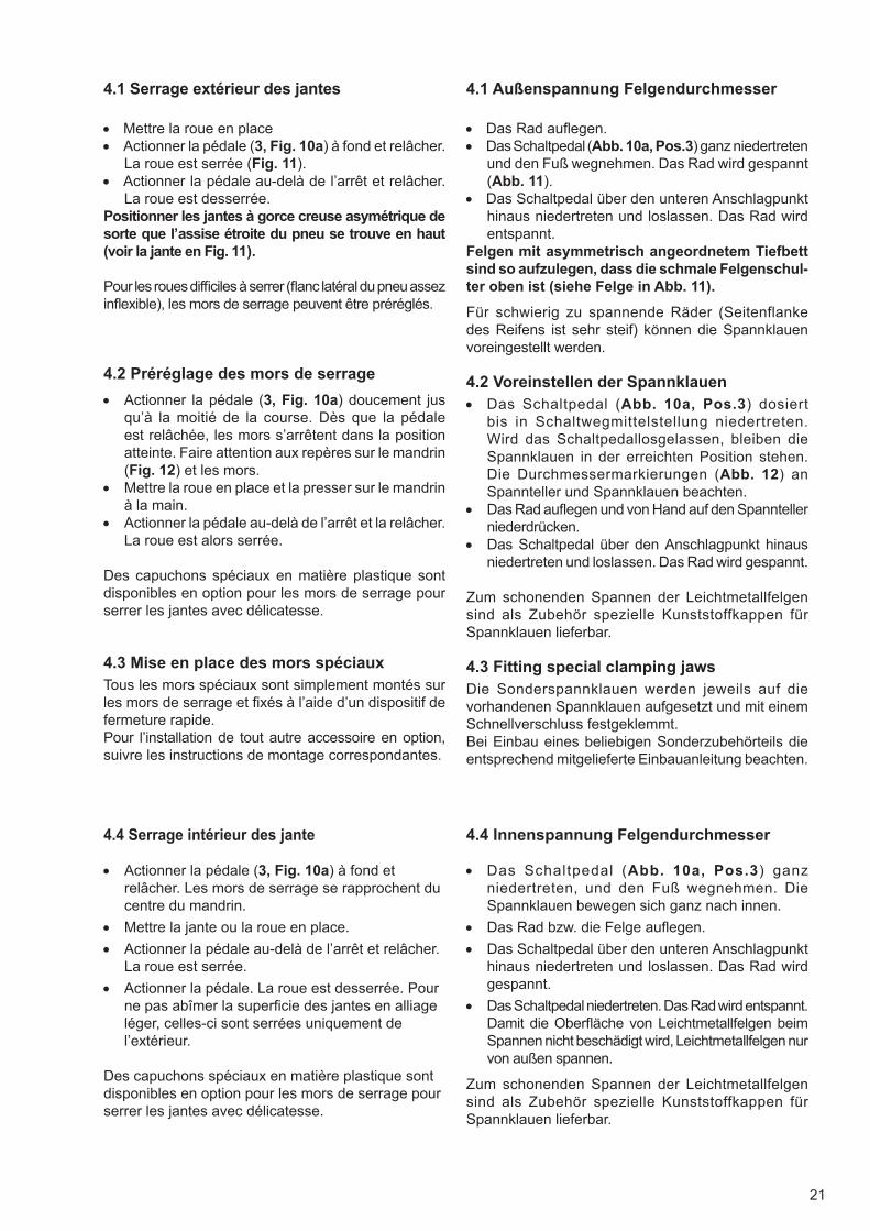
4.1 Serrage extérieur des jantes
• Mettre la roue en place• Actionner la pédale (3, Fig. 10a) à fond et relâcher.
La roue est serrée (Fig. 11).• Actionner la pédale au-delà de l’arrêt et relâcher.
La roue est desserrée.Positionner les jantes à gorce creuse asymétrique de sorte que l’assise étroite du pneu se trouve en haut (voir la jante en Fig. 11).
Pour les roues diffi ciles à serrer (fl anc latéral du pneu assez infl exible), les mors de serrage peuvent être préréglés.
4.2 Préréglage des mors de serrage
• Actionner la pédale (3, Fig. 10a) doucement jusqu’à la moitié de la course. Dès que la pédaleest relâchée, les mors s’arrêtent dans la positionatteinte. Faire attention aux repères sur le mandrin(Fig. 12) et les mors.
• Mettre la roue en place et la presser sur le mandrinà la main.
• Actionner la pédale au-delà de l’arrêt et la relâcher.La roue est alors serrée.
Des capuchons spéciaux en matière plastique sont disponibles en option pour les mors de serrage pour serrer les jantes avec délicatesse.
4.3 Mise en place des mors spéciaux Tous les mors spéciaux sont simplement montés sur les mors de serrage et fi xés à l’aide d’un dispositif de fermeture rapide.Pour l’installation de tout autre accessoire en option, suivre les instructions de montage correspondantes.
4.4 Serrage intérieur des jante
• Actionner la pédale (3, Fig. 10a) à fond etrelâcher. Les mors de serrage se rapprochent ducentre du mandrin.
• Mettre la jante ou la roue en place.
• Actionner la pédale au-delà de l’arrêt et relâcher.La roue est serrée.
• Actionner la pédale. La roue est desserrée. Pourne pas abîmer la superfi cie des jantes en alliageléger, celles-ci sont serrées uniquement del’extérieur.
Des capuchons spéciaux en matière plastique sont disponibles en option pour les mors de serrage pour serrer les jantes avec délicatesse.
22
14
15
1
2
3
4
5
4
1
2 3
1
2
2
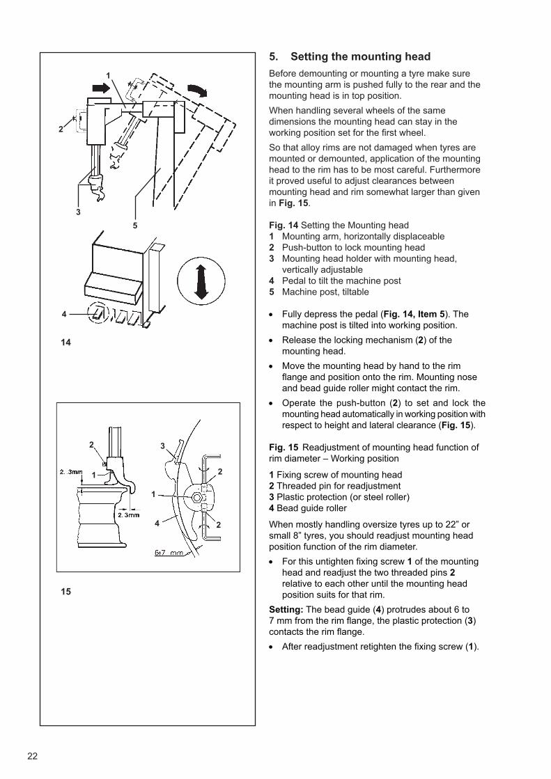
5. Setting the mounting head
Before demounting or mounting a tyre make sure the mounting arm is pushed fully to the rear and the mounting head is in top position.
When handling several wheels of the same dimensions the mounting head can stay in the working position set for the fi rst wheel.
So that alloy rims are not damaged when tyres are mounted or demounted, application of the mounting head to the rim has to be most careful. Furthermore it proved useful to adjust clearances between mounting head and rim somewhat larger than given in Fig. 15.
Fig. 14 Setting the Mounting head 1 Mounting arm, horizontally displaceable 2 Push-button to lock mounting head 3 Mounting head holder with mounting head,
vertically adjustable 4 Pedal to tilt the machine post 5 Machine post, tiltable
• Fully depress the pedal (Fig. 14, Item 5). Themachine post is tilted into working position.
• Release the locking mechanism (2) of themounting head.
• Move the mounting head by hand to the rimfl ange and position onto the rim. Mounting noseand bead guide roller might contact the rim.
• Operate the push-button (2) to set and lock themounting head automatically in working position withrespect to height and lateral clearance (Fig. 15).
Fig. 15 Readjustment of mounting head function of rim diameter – Working position
1 Fixing screw of mounting head 2 Threaded pin for readjustment 3 Plastic protection (or steel roller) 4 Bead guide roller
When mostly handling oversize tyres up to 22” or small 8” tyres, you should readjust mounting head position function of the rim diameter.
• For this untighten fi xing screw 1 of the mountinghead and readjust the two threaded pins 2relative to each other until the mounting headposition suits for that rim.
Setting: The bead guide (4) protrudes about 6 to 7 mm from the rim fl ange, the plastic protection (3) contacts the rim fl ange.
• After readjustment retighten the fi xing screw (1).
23
5. Einstellen des Montierkopfes
Vor Beginn einer Reifendemontage bzw. einer Reifenmontage darauf achten, dass der Montierarm bis zum Anschlag nach hinten eingeschoben ist und der Montierkopf in der obersten Stellung steht.
Bei Bearbeitung mehrerer Räder mit gleichen Radmaßen kann der Montierkopf in der am ersten Rad eingestellten Arbeitsposition bleiben.
Damit Leichtmetallfelgen bei der Reifenmontage bzw. -demontage nicht beschädigt werden, ist der Antastvorgang des Montierkopfes an die Felge mit entsprechender Sorgfalt vorzunehmen. Außerdem ist es zweckmäßig, die Abstände zwischen Montierkopf und Felge etwas größer einzustellen als auf Abb. 15 angegeben.
Abb. 14 Einstellen des Montierkopfes
1 Montierarm, horizontal verschiebbar 2 Drucktaster für Arretierung des Montierkopfes 3 Montierkopfhalter mit Montierkopf,
höhenverstellbar 4 Schaltpedal für Kippbewegung der Montiersäule 5 Montiersäule, kippbar
• Das Schaltpedal (Abb. 14, Pos. 5) ganz niedertreten.Die Montiersäule kippt in die Arbeitsposition heran.
• Die Arretierung (2) des Montierkopfes lösen.
• Den Montierkopf von Hand an das Felgenhornheranführen und aufsetzen, hierbei können derMontierfinger und die Wulstführungsrolle diejeweilige Felgenkontur berühren.
• Den Drucktaster (2) betätigen, um den Montierkopfautomatisch in Höhe und seitlichem Ab-stand inseine Arbeitsposition einzustellen und zu arretieren(Abb. 15).
Abb. 15 Nachstellen der Montierkopfl age zum Felgendurchmesser – Arbeitsposition
1 Halteschraube des Montierkopfes 2 Gewindestift für Verstellung 3 Kunststoffschutz (oder Stahlanlaufrolle) 4 Wulstführungsrolle
Bei vorwiegender Bearbeitung von großen Rädern bis 22” bzw. kleinen 8” Rädern ist es zweckmäßig, die Montierkopfstellung dem Felgendurchmesser anzupassen.
• Hierzu die Halteschraube 1 des Montierkopfes lösen,und die beiden Gewindestifte 2 so gegeneinanderverstellen, dass die Lage des Montierkopfes derFelge entspricht.
Einstellung: Die Wulstführung (4) steht ca. 6 bis 7 mm am Felgenhorn über, der Kunststoffschutz (3) liegt am Felgenhorn an.
• Nach dem Einstellen die Halteschraube (1)wieder festziehen.
5. Réglage de la tête de montage
Avant le démontage ou le montage d’un pneu, faire attention à ce que le bras de montage soit poussé complètement en arrière et que la tête de montage soit en position supérieure.
Si plusieurs roues de dimensions identiques sont manipulées, il suffi t de régler la tête de montage une seule fois et de la laisser ensuite dans cette position de travail.
Afi n de ne pas endommager les jantes en alliage léger pendant le montage ou démontage du pneu, l’approche de la tête de montage de la jante doit se faire avec beaucoup de soin. De plus, il est recommandé d’augmenter un peu plus les écartements entre la tête de montage et la jante par rapport aux instructions de la Fig. 15.
Fig. 14 Réglage de la tête de montage 1 Bras de montage, à déplacement horizontal 2 Bouton-poussoir pour bloquer la tête de montage 3 Porte-tête de montage avec tête de montage,
réglable en hauteur 4 Pédale pour basculer le montant de machine 5 Montant de machine, inclinaible.
• Appuyer la pédale à fond (Fig. 14, Pos. 5). Le montantde la machine est basculé en position de travail.
• Débloquer la tête de montage.
• Approcher la tête de montage à la main du rebordde la jante et la poser dessus. Le bec de montageet le galet guide-talon peuvent toucher la jante.
• Appuyer sur le bouton-poussoir (2) pour régler latête de montage automatiquement en hauteur etlatéralement et l’arrêter en position de travail (Fig. 15).
Fig. 15 Ajustage de la tête de montage en fonction du diamètre de jante – Position de travail
1 Vis de fi xation de la tête de montage 2 Goupille fi letée pour le réglage 3 Protection en plastique (ou butée en acier) 4 Galet guide-talon
Si vous traitez surtout des roues très grandes ayant jusqu’à 22” de diamétre, ou des petites roues de 8”, il est recommandé de régler la tête de montage en fonction du diamètre de la jante.
• Dans ce but, desserrer la vis de fi xation 1 de latête de montage et rajuster les deux goupillesfi letées 2, l’une par rapport à l’autre, pour modifi erla position de la tête en fonction de la jante.
Réglage: Le galet guide-talon (4) dépasse le rebord de la jante d’environ 6 à 7 mm, la protection en plastique (3) est en contact avec le rebord de la jante.
• Après l’ajustage, resserrer la vis de fi xation (1).
24
6. Fundamentals of demountingand mounting a tire
1 Use the special plastic parts for clamping, the plastic mounting head and special tire levers (coated or the like) so as not to damage the rims, in particular alloy rims, when mounting or demounting the tires.
2 Prior to demounting or mounting a commercial tire lubricant should be applied onto the bead outer and inner sides, the rim fl anges and shoulders, and the Denloc groove with TD tires. Never use other agents only supposed to lubricate!
3 Prior to demounting or mounting of a tire check the rim for damage (deformation and/or damaged surface of rim fl anges, lateral and radial run-out of rim, corrosion, wear in general).
4 With some tire types, pay attention to the outer sidewall rib, or to direction of rotation as indicated on the tire.
5 When infl ating the tire increase pressure gradually and possibly by constantly observing the bead. A seating pressure of 3.3 bar should not be exceeded. Make sure the mounting guide rib of the tire is correctly seated with respect to the rim fl ange. A fi nal pressure of 3.5 bar should not be exceeded (also refer to Chapter: Beading Tubeless tires).
6 Always fi t tires on rims of proper size (identical nominal diameter); this means for example no tires of nominal size in mm on rims of nominal size in inches and vice versa.
7 No tubes may be fi tted in TD tires.
8 At any rate pay attention to special mounting and de mounting instructions by tire makers.
25
6. Grundsätzliche Hinweise zur Montageund Demontage eines Reifens
1 Um bei den Arbeitsgängen die Felgen, besonders die Leichtmetallfelgen, nicht zu beschädigen, sollten die Kunststoffschutzteile zum Spannen, der Kunststoffmontagekopf und präparierte Montierhebel (Schutzüberzug, ummantelte Ausführung oder ähnliches) verwendet werden.
2 Vor der Demontage bzw. Montage eines Reifens die Wulstaußen- und -innenseiten, die Felgenhörner und Felgenschultern, bei TD-Reifen auch die Denloc-Rille, mit einem geeigneten handelsüblichen Gleitmittel (Fluid oder Gleitpaste) ausreichend bestreichen. Keinesfalls andere, vermeintliche Gleitmittel verwenden.
3 Vor jeder Demontage bzw. Montage eines Reifens die Felge auf eventuelle Beschädigungen (Verformung und/ oder Oberfl ächenbeschädigung der Felgenhörner, Höhen- und Seitenschlag der Felge, Korrosionsschäden, allgemeiner Verschleiß) kontrollieren.
4 Bei einigen Reifentypen ist bei der Montage auf die äußere Scheuerleiste oder auf die am Reifen angegebene Montagerichtung zu achten.
5 Beim Füllen eines Reifens den Luftdruck möglichst unter ständiger Beobachtung des Wulstes stufenweise aufbauen. Ein Springdruck von 3,3 bar sollte nicht überschritten werden. Auf den exakten Verlauf der Kennlinie des Reifens zur Felge achten. 3,5 bar Setzdruck nicht überschreiten (siehe auch Punkt 9. Füllen der Reifen). Reifen, die einen höheren Druck benötigen, sind in geeigneten Fülleinrichtungen (Schutzkäfi g etc.) zu befüllen.
6 Reifen immer nur auf Felgen der passenden Größe (gleiches Durchmesser-Nennmaß) montieren; also auch keine Reifen mit Nennmaß in mm auf Felgen mit Nennmaß in Zoll und umgekehrt.
7 TD-Reifen nur schlauchlos montieren, die Verwendung eines Schlauches ist hier keinesfalls erlaubt.
8 Spezielle Demontage-bzw. Montagehinweise der Reifenhersteller beachten.
6. Règles fondamentales de montageet de démontage des pneus
1 Utiliser les pièces spéciales en matière plastique, la tête de montage en plastique et les leviers de montage spéciaux (à couche spéciale ou similaire) pour ne pas endommager les jantes, particulièrement les jantes en alliage léger, pendant le montage ou démontage des pneus.
2 Avant le démontage ou montage d’un pneu, appliquer un lubrifi ant courant pour pneus (liquide ou pâte) en quantité abondante sur les côtés intérieur et extérieur du talon, les rebords de jante et les assises du pneu ainsi que la gorge Denloc des pneus TD. Ne jamais utiliser d’autres prétendus lubrifi ants!
3 Avant le démontage ou montage d’un pneu, contrôler si la jante présente des défauts (déformations et/ou surface endommagée des rebords de la jante, voilage et faux rond de la jante, corrosion, usure générale).
4 Il existe des types de pneus où il importe de faire attention à la nervure de fl anc ou au sens de rotation indiqué sur le pneu.
5 Lors du gonfl age du pneu, augmenter la pression pas à pas tout en observant constamment le talon. Une pression de claquage de 3,3 bar ne devrait pas être dépassée. Veiller à ce que le fi let de centrage du pneu soit centré exactement par rapport au rebord de la jante. Ne pas dépasser une pression de mise en place défi nitive de 3,5 bar (cf. également § 10. Gonfl age des pneus). Les pneus qui demandent une pression supérieure à 3,3 bar doivent être gonfl és dans un dispositif de gonfl age approprié (par ex. cage de sécurité, etc.).
6 Faire attention à chausser toujours les pneus sur des jantes de dimensions correspondantes (de diamètres nominaux identiques). Donc, ne monter en aucun cas par exemple, des pneus de dimensions nominales en mm sur des jantes de dimensions nominales en pouces et vice versa.
7 Pneus TD ne peuvent pas être équipés de chambre à air.
8 Observer les instructions spéciales de montage et de démontage des fabricants de pneus.
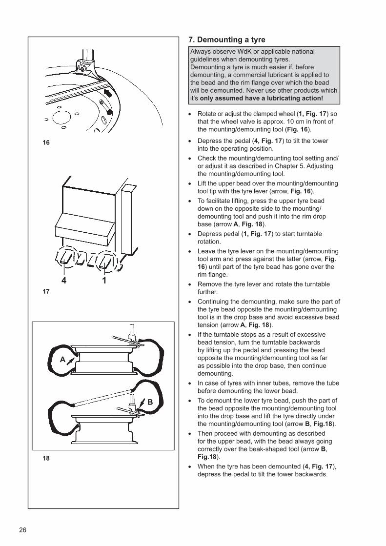
26
16
17
18
14
A
B
7. Demounting a tyre
Always observe WdK or applicable national guidelines when demounting tyres.Demounting a tyre is much easier if, before demounting, a commercial lubricant is applied to the bead and the rim fl ange over which the bead will be demounted. Never use other products which it’s only assumed have a lubricating action!
• Rotate or adjust the clamped wheel (1, Fig. 17) sothat the wheel valve is approx. 10 cm in front ofthe mounting/demounting tool (Fig. 16).
• Depress the pedal (4, Fig. 17) to tilt the towerinto the operating position.
• Check the mounting/demounting tool setting and/or adjust it as described in Chapter 5. Adjustingthe mounting/demounting tool.
• Lift the upper bead over the mounting/demountingtool tip with the tyre lever (arrow, Fig. 16).
• To facilitate lifting, press the upper tyre beaddown on the opposite side to the mounting/demounting tool and push it into the rim dropbase (arrow A, Fig. 18).
• Depress pedal (1, Fig. 17) to start turntablerotation.
• Leave the tyre lever on the mounting/demountingtool arm and press against the latter (arrow, Fig.16) until part of the tyre bead has gone over therim fl ange.
• Remove the tyre lever and rotate the turntablefurther.
• Continuing the demounting, make sure the part ofthe tyre bead opposite the mounting/demountingtool is in the drop base and avoid excessive beadtension (arrow A, Fig. 18).
• If the turntable stops as a result of excessivebead tension, turn the turntable backwardsby lifting up the pedal and pressing the beadopposite the mounting/demounting tool as faras possible into the drop base, then continuedemounting.
• In case of tyres with inner tubes, remove the tubebefore demounting the lower bead.
• To demount the lower tyre bead, push the part ofthe bead opposite the mounting/demounting toolinto the drop base and lift the tyre directly underthe mounting/demounting tool (arrow B, Fig.18).
• Then proceed with demounting as describedfor the upper bead, with the bead always goingcorrectly over the beak-shaped tool (arrow B,Fig.18).
• When the tyre has been demounted (4, Fig. 17),depress the pedal to tilt the tower backwards.

27
7. Demontieren eines Reifens
Bei der Demontage von Reifen sind grundsätzlich die WdKLeitlinien (Wirtschaftsverband der deutschen Kautschukindustrie) zu beachten. Die Demontage eines Reifens wird wesentlich erleichtert, wenn vor dem Demontiervorgang die Wulstpartie und das Felgenhorn, über das montiert wird, mit einer handelsüblichen Montagepaste bestrichen werden. Keinesfalls andere, vermeintliche Gleitmittel verwenden!
• Das aufgespannte Rad so drehen (1, Abb. 17) bzw.stellen, dass das Radventil etwa 10 cm vor demMontierkopf steht (Abb. 16).
• Das Schaltpedal niederdrücken (4, Abb. 17). DieMontiersäule kippt heran.
• Die Einstellung des Montierkopfes prüfen bzw.wie unter Punkt 5. Einstellen des Montierkopfesbeschrieben einstellen.
• Den oberen Reifenwulst mit dem Montierhebel überdie Nase des Montierkopfs hebeln (Pfeil, Abb. 16).
• Um das Aufhebeln zu erleichtern, auf der demMontierkopf gegenüberliegenden Radseite denoberen Reifenwulst nach unten drücken und in dasFelgentiefbett hineinschieben (Pfeil A, Abb. 18).
• Das Schaltpedal (1, Abb. 17) niedertreten(Arbeitsbewegung des Spanntellers).
• Den Montierhebel noch etwas auf dem Steg desMontierkopfes halten und gleichzeitig gegen denMontierkopf andrücken (Pfeil, Abb. 16), bis ein Teildes Reifenwulsts über das Felgenhorn gelaufen ist.
• Den Montierhebel wegnehmen und den Spanntellerweiterdrehen lassen.
• Während des weiteren Demontagevorgangs darauf
achten, dass der Reifenwulstteil gegenüberdem Montierkopf im Tiefbett liegt und zu großeWulstspannung vermieden wird (Pfeil A, Abb. 18).
• Sollte der Spannteller infolge zu hoherWulstspannung stehen bleiben, den Spanntellerdurch Anheben des Schaltpedals etwaszurückdrehen, den Reifenwulst gegenüber demMontierkopf so weit wie möglich in das Tiefbetteinschieben und die Demontage fortsetzen.
• Bei Schlauchreifen den Schlauch vor derDemontage des unteren Reifenwulstsherausnehmen.
• Zum Aufhebeln des unteren Reifenwulsts denWulstteil gegenüber dem Montierkopf in dasTiefbett einschieben, und den Reifen direkt unterdem Montierkopf anheben (Pfeil B, Abb. 18).
• Nach dem Aufhebeln die Demontage in gleicherWeise durchführen wie beim oberen Wulst.Dabei muss der Wulst immer korrekt über denMontierfi nger muss (Pfeil B, Abb. 18).
• Nach der Demontage das Schaltpedal (4, Abb. 17)niedertreten. Die Montiersäule kippt nach hinten.
7. Démontage des pneus
Observer strictement les règlements nationaux en vigueur pour le démontage des pneus.Le démontage d’un pneu est nettement facilité s’il est précédé de l’application d’un lubrifi ant approprié sur le talon et sur le bord de la jante d’où il sera démonté. Ne jamais utiliser un produit lubrifi ant non spécifi que pour pneus!
• Tourner ou régler la roue bloquée (1, Fig. 17)de manière à ce que la roue se trouve à 10 cmenviron devant la tête de montage (Fig. 16).
• Appuyer sur la pédale (4, Fig. 17) pour incliner lemontant de machine en position de travail.
• Contrôler le réglage de la tête de montage, oula régler suivant le § 5. Réglage de la tête demontage.
• Passer le talon supérieur, par l’intermédiaire dulevier de montage, au-dessus du bec de la tête demontage (fl èche, Fig. 16).
• Pour faciliter cette opération, appuyer sur le talonsupérieur, opposé à la tête de montage, et le faireglisser dans la base de la jante (fl èche A, Fig. 18).
• Appuyer sur la pédale (1, Fig. 17) pour mettre lemandrin en rotation.
• Laisser le levier de montage sur la traverse dela tête de montage et le presser contre la tête(fl èche, Fig. 16) jusqu’à ce qu’une partie du talonsoit montée sur le rebord de jante.
• Ensuite enlever le levier et continuer à fairetourner le andrin.
• En continuant le démontage, veiller à ce que le talonopposé à la tête de montage se trouve dans la basecreuse de la jante et qu’une tension extrême du talonsoit empêchée (fl èche A, Fig. 18).
• Si le mandrin s’arrête par ce que le talon est tropserré, faire tourner le mandrin en arrière en soulevantla prédale et en pressant le talon opposé à la têtede montage dans la base creuse de la jante. Puiscontinuer le démontage.
• S’il s’agit de pneus avec chambre à air, enlever lachambre à air avant le démontage du deuxièmetalon.
• Pour démonter le talon inférieur du pneu, presserle talon opposé à la tête de montage dans la basecreuse et appliquer le levier directement au-dessousde la tête de montage (fl èche B, Fig. 18).
• Continuer le démontage comme décrit pour letalon supérieur en veillant à ce que le talon passetoujours correctement au-dessus du bec demontage (fl èche B, Fig. 18).
• Après le démontage du pneu, appuyer sur la pédale(4, Fig. 17) pour incliner le montant en arrière.
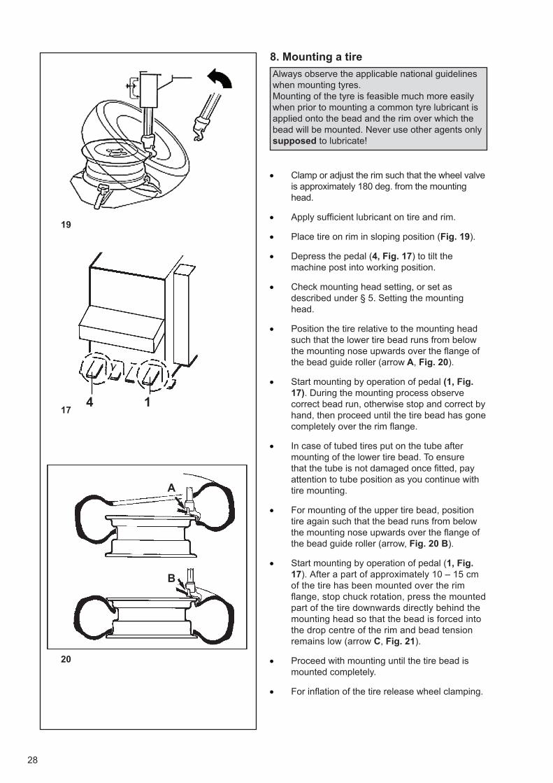
28
19
17
20
14
A
B
8. Mounting a tire
Always observe the applicable national guidelines when mounting tyres. Mounting of the tyre is feasible much more easily when prior to mounting a common tyre lubricant is applied onto the bead and the rim over which the bead will be mounted. Never use other agents only supposed to lubricate!
• Clamp or adjust the rim such that the wheel valveis ap proximately 180 deg. from the mountinghead.
• Apply suffi cient lubricant on tire and rim.
• Place tire on rim in sloping position (Fig. 19).
• Depress the pedal (4, Fig. 17) to tilt themachine post into working position.
• Check mounting head setting, or set asdescribed under § 5. Setting the mountinghead.
• Position the tire relative to the mounting headsuch that the lower tire bead runs from belowthe mounting nose upwards over the fl ange ofthe bead guide roller (arrow A, Fig. 20).
• Start mounting by operation of pedal (1, Fig.17). During the mounting process observecorrect bead run, otherwise stop and correct byhand, then proceed until the tire bead has gonecompletely over the rim fl ange.
• In case of tubed tires put on the tube aftermounting of the lower tire bead. To ensurethat the tube is not dam aged once fi tted, payattention to tube position as you continue withtire mounting.
• For mounting of the upper tire bead, positiontire again such that the bead runs from belowthe mounting nose upwards over the fl ange ofthe bead guide roller (arrow, Fig. 20 B).
• Start mounting by operation of pedal (1, Fig.17). After a part of approximately 10 – 15 cmof the tire has been mounted over the rimfl ange, stop chuck rotation, press the mountedpart of the tire downwards directly behind themounting head so that the bead is forced intothe drop centre of the rim and bead tensionremains low (arrow C, Fig. 21).
• Proceed with mounting until the tire bead ismounted completely.
• For infl ation of the tire release wheel clamping.
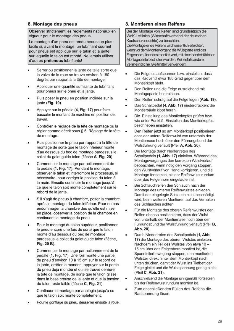
29
8. Montieren eines Reifens
Bei der Montage von Reifen sind grundsätzlich die WdK-Leitlinien (Wirtschaftsverband der deutschen Kautschukindustrie) zu beachten. Die Montage eines Reifens wird wesentlich erleichtert, wenn vor dem Montiervorgang die Wulstpartie und das Felgenhorn, über das montiert wird, mit einer handelsüblichen Montagepaste bestrichen werden. Keinesfalls andere, vermeintliche Gleitmittel verwenden!
• Die Felge so aufspannen bzw. einstellen, dassdas Radventil etwa 180 Grad gegenüber demMontierkopf steht.
• Den Reifen und die Felge ausreichend mitMontagepaste bestreichen.
• Den Reifen schräg auf die Felge legen (Abb. 19).
• Das Schaltpedal (4, Abb. 17) niederdrücken; dieMontiersäule kippt heran.
• Die Einstellung des Montierkopfes prüfen bzw.wie unter Punkt 5. Einstellen des Montierkopfesbeschrieben einstellen.
• Den Reifen jetzt so am Montierkopf positionieren,dass der untere Reifenwulst von unterhalb derMontiernase hoch über den Führungsbund derWulstführung verläuft (Pfeil A, Abb. 20).
• Die Montage durch Niedertreten desSchaltpedals (1, Abb. 17) einleiten. Während desMontagevorganges den korrekten Wulstverlaufbeobachten, wenn nötig den Vorgang stoppen,den Wulstverlauf von Hand korrigieren, und dieMontage fortsetzen, bis der Reifenwulst rundumüber das Felgenhorn eingelaufen ist.
• Bei Schlauchreifen den Schlauch nach derMontage des unteren Reifenwulstes einlegen.Damit der eingelegte Schlauch nicht beschädigtwird, beim weiteren Montieren auf das Verhaltendes Schlauches achten.
• Für die Montage des oberen Reifenwulstes denReifen ebenso positionieren, dass der Wulstvon unterhalb der Montiernase hoch über denFührungsbund der Wulstführung verläuft (Pfeil B,Abb. 20).
• Durch Niedertreten des Schaltpedals (1, Abb.17) die Montage des oberen Wulstes einleiten.Nachdem ein Teil des Wulstes von etwa 10 – 15 cm über das Felgenhorn montiert ist, die Spanntellerbewegung stoppen, den montierten Wulstteil direkt hinter dem Montierkopf nach unten drücken, damit der Wulst ins Tiefbett der Felge gleitet und die Wulstspannung gering bleibt (Pfeil C, Abb. 21).
• Anschließend die Montage sinngemäß fortsetzen,bis der Reifenwulst rundum montiert ist.
• Zum anschließenden Füllen des Reifens dieRadspannung lösen.
8. Montage des pneus
Observer strictement les règlements nationaux en vigueur pour le montage des pneus.
Le montage d’un pneu est rendu beaucoup plus facile si, avant le montage, un lubrifi ant courant pour pneus est appliqué sur le talon et la jante sur laquelle le talon est monté. Ne jamais utiliser d’autres prétendus lubrifi ants!
• Serrer ou positionner la jante de telle sorte quela valve de la roue se trouve environ à 180degrés par rapport à la tête de montage.
• Appliquer une quantité suffi sante de lubrifi antpour pneus sur le pneu et la jante.
• Puis poser le pneu en position inclinée sur lajante (Fig. 19).
• Appuyer sur la pédale (4, Fig. 17) pour fairebasculer le montant de machine en position detravail.
• Contrôler le réglage de la tête de montage ou larégler comme décrit sous § 5. Réglage de la têtede montage.
• Puis positionner le pneu par rapport à la tête demontage de sorte que le talon inférieur monted’au dessous du bec de montage pardessus lecollet du galet guide talon (fl èche A, Fig. 20).
• Commencer le montage par actionnement dela pédale (1, Fig. 17). Pendant le montage,observer le talon et interrompre le processus, sinécessaire, pour corriger la position du talon àla main. Ensuite continuer le montage jusqu’àce que le talon soit monté complètement sur lerebord de la jante.
• S’il s’agit de pneus à chambre, poser la chambreaprès le montage du talon inférieur. Pour ne pasendommager la chambre dès qu’elle est miseen place, observer la position de la chambre encontinuant le montage du pneu.
• Pour le montage du talon supérieur, positionnerle pneu encore une fois de sorte que le talonmonte d’au dessous du bec de montagepardessus le collet du galet guide talon (fl èche,Fig. 20 B).
• Commencer le montage par actionnement de lapédale (1, Fig. 17). Une fois monté une partiedu pneu d’environ 10 à 15 cm sur le rebord dela jante, arrêter le mandrin, appuyer sur la partiedu pneu déjà montée et qui se trouve derrièrela tête de montage, de sorte que le talon glissedans la base creuse de la jante et que la tensiondu talon reste faible (fl èche C, Fig. 21).
• Continuer le montage par analogie jusqu’à ceque le talon soit monté complètement.
• Pour le gonfl age du pneu, desserrer ensuite la roue.
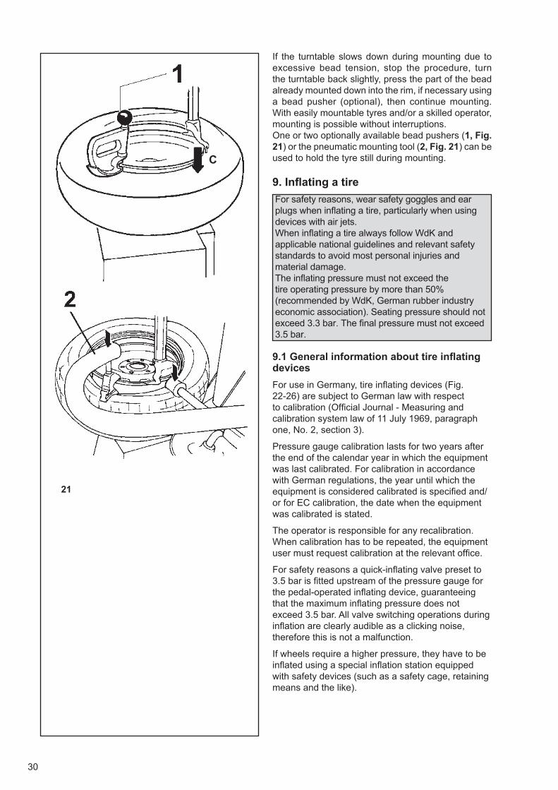
30
21
C
If the turntable slows down during mounting due to excessive bead tension, stop the procedure, turn the turntable back slightly, press the part of the bead already mounted down into the rim, if necessary using a bead pusher (optional), then continue mounting. With easily mountable tyres and/or a skilled operator, mounting is possible without interruptions.One or two optionally available bead pushers (1, Fig. 21) or the pneumatic mounting tool (2, Fig. 21) can beused to hold the tyre still during mounting.
9. Infl ating a tire
For safety reasons, wear safety goggles and ear plugs when infl ating a tire, particularly when using devices with air jets. When infl ating a tire always follow WdK and applicable national guidelines and relevant safety standards to avoid most personal injuries and material damage. The infl ating pressure must not exceed the tire operating pressure by more than 50% (recommended by WdK, German rubber industry economic association). Seating pressure should not exceed 3.3 bar. The fi nal pressure must not exceed 3.5 bar.
9.1 General information about tire infl ating devices
For use in Germany, tire infl ating devices (Fig. 22-26) are subject to German law with respect to calibration (Offi cial Journal - Measuring and calibration system law of 11 July 1969, paragraph one, No. 2, section 3).
Pressure gauge calibration lasts for two years after the end of the calendar year in which the equipment was last calibrated. For calibration in accordance with German regulations, the year until which the equipment is considered calibrated is specifi ed and/or for EC calibration, the date when the equipment was calibrated is stated.
The operator is responsible for any recalibration. When calibration has to be repeated, the equipment user must request calibration at the relevant offi ce.
For safety reasons a quick-infl ating valve preset to 3.5 bar is fi tted upstream of the pressure gauge for the pedal-operated infl ating device, guaranteeing that the maximum infl ating pressure does not exceed 3.5 bar. All valve switching operations during infl ation are clearly audible as a clicking noise, therefore this is not a malfunction.
If wheels require a higher pressure, they have to be infl ated using a special infl ation station equipped with safety devices (such as a safety cage, retaining means and the like).
31
Sollte der Spannteller infolge zu hoher Wulstspannung stehenbleiben, den Vorgang verlangsamt, durch Anheben des Schaltpedals den Spannteller etwas zurückdrehen, den schon montierten Reifenwulst nochmals kräftig nach unten in die Felge drücken, eventuell Wulstniederhalter (Sonderzubehör) einsetzen und die Montage fortsetzen. Bei leicht montierbaren Reifen bzw. geübter Bedienperson ist die Montage auch in einem Zug durchführbar. Für das Niederdrücken des Reifens während der Montage können ein oder zwei als Zubehör lieferbare Wulstniederhalter (1, Abb. 21) oder die pneumatische Montagehilfe (2, Abb. 21) verwendet werden.
9. Füllen der Reifen
Aus Sicherheitsgründen ist beim Befüllen eines Reifens, besonders von Füllanlagen mit Füllstoß, entsprechender Gehörschutz und eine Schutzbrille zu tragen.Beim Füllen eines Reifens mit Luft sind die WdK-Leitlinien sowie einige allgemeine Sicherheitskriterien zu beachten, damit eine Gefährdung für Personal und Arbeitsmittel weitgehend ausgeschlossen ist.Der Montagefülldruck darf den Betriebsdruck des Reifens nur bis zu 50 % überschreiten (Empfehlung des WdK – Wirtschaftsverband der Deutschen Kautschukindustrie).Der Springdruck soll 3,3 bar, der Setzdruck darf 3,5 bar nicht übersteigen.
9.1 Allgemeines zur Reifenfüllanlage
Die Reifenfüllanlagen (Abb. 22-26) müssen bei Verwendung in der Bundesrepublik Deutschland geeicht sein und unterliegen der gesetzlich vorgeschriebenen Eichpfl icht (Bundesgesetzblatt – Gesetz über Mess- und Eichwesen vom 11. Juli 1969, Erster Abschnitt § 2, Abs. 3).
Die Gültigkeit der Eichung für Luftdruckmessgeräte beträgt zwei Jahre und wird in Jahren nach Ablauf des Kalenderjahrs bemessen, in dem das Gerät zuletzt geeicht wurde. Bei Eichung nach deutscher Norm wird das Jahr angegeben, bis wann das Gerät geeicht ist, bzw. bei EG-Eichung, wann das Gerät geeicht wurde.
Für die jeweilige Nacheichung ist der Betreiber verantwortlich.Er wird hiermit aufgefordert, zum jeweiligen Zeitpunkt die Nacheichung beim zuständigen Eichamt zu beantragen.
Aus Sicherheitsgründen ist vor dem Manometer für die pedalbetätigte Füllanlage ein auf 3,5 bar eingestelltes Schnellbefüllventil eingebaut, das gewährleistet, dass der maximale Befülldruck nicht mehr als 3,5 bar beträgt. Die Schaltvorgänge sind als Klacken während des Füllvorgangs deutlich hörbar und stellen keine Fehlfunktion dar.
Müssen Räder mit höherem Setzdruck bearbeitet werden, ist zum Befüllen solcher Räder eine spezielle Füllstation zu verwenden, welche mit Sicherheitseinrichtungen (z. B. Sicherheitskäfi g, Festhaltevorrichtung usw.) versehen ist.
Si le mandrin ralentit pendant le montage à cause du talon trop serré, arrêter la procédure, tourner légèrement en arrière le mandrin, presser le talon qui est déjà monté avec force vers le bas dans la jante, le cas échéant, utiliser un presse-talon (en option), et poursuivre le montage. Pour immobiliser le pneu pendant le montage, Il est possible d’utiliser un ou deux presse-talons disponibles comme options (1, Fig. 21) ou de l’outil de montage à actionnement pneumatique (2, Fig. 21), qui sont disponibles en option.
9. Gonfl age des pneus
Pour des raisons de sécurité, porter des lunettes de protection et des protège-oreilles pendant le gonfl age du pneu, notamment si on utiliser des systèmes à jet.
Pour le gonfl age des pneus, observer toujours les règlements nationaux en vigueur et les normes de sécurité qui s’appliquent pour exclure tout dommage à des personnes ou tout dommage matériel.La pression de gonfl age ne doit pas dépasser la pression d’exercice du pneu de plus de 50 pour-cent (recommandé par l’Union des Industries de Caoutchouc Allemande).La pression de gonfl age ne doit pas dépasser 3,3 bar, la pression programmée ne doit pas dépasser 3,5 bars.
9.1 Généralités concernant le dispositif de
gonfl age
Pour un emploi en Allemagne, les systèmes de gonfl age (Fig. 22-26) sont soumis à la législation allemande qui prévoit l’obligation de l’étalonnage (Gazette Offi cielle - Loi sur le système de mesure et étalonnage du 11 juillet 1969, premier alinéa , par. 3).
L’étalonnage des manomètres a une durée de deux ans à partir du dernier jour de l’année à laquelle l’appareil a été étalonné la dernière fois. Pour l’étalonnage suivant la norme allemande, il est indiqué avec précision l’année à laquelle il faut refaire l’étalonnage tandis que pour la réglementation européenne, il est indiqué l’année à laquelle l’appareil a été étalonné.
L’opérateur est responsable de l’éventuelle réétalonnage. Quand un nouvel étalonnage doit être fait, l’utilisateur de l’appareil devra le demander au service compétent.
Pour des raisons de sécurité, une valve à gonfl age rapide préréglée à 3,5 bars est montée en amont du manomètre et garantit que le dispositif de gonfl age actionné par la pédale aura une pression maximale de gonfl age de 3,5 bars. Le passage d’un état à l’autre de la valve au cours du gonfl age est clairement perceptible: il ne s’agit pas d’un défaut de fonctionnement.
S’il faut gonfl er des pneus sous une pression plus élevée, utiliser un poste de gonfl age spécial équipé de dispositifs de sécurité (ex. : une cage de sécurité, des moyens de retenue, etc.).
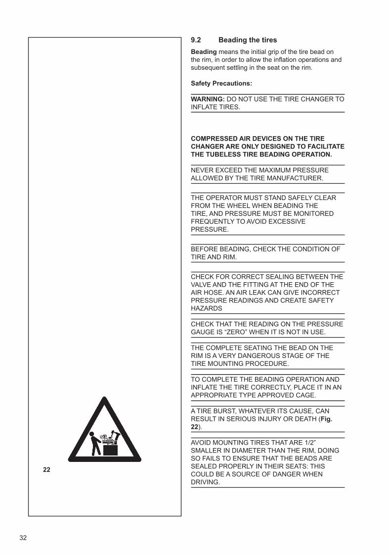
32
22
9.2 Beading the tires
Beading means the initial grip of the tire bead on the rim, in order to allow the infl ation operations and subsequent settling in the seat on the rim.
Safety Precautions:
WARNING: DO NOT USE THE TIRE CHANGER TO INFLATE TIRES.
COMPRESSED AIR DEVICES ON THE TIRE CHANGER ARE ONLY DESIGNED TO FACILITATE THE TUBELESS TIRE BEADING OPERATION.
NEVER EXCEED THE MAXIMUM PRESSURE ALLOWED BY THE TIRE MANUFACTURER.
THE OPERATOR MUST STAND SAFELY CLEAR FROM THE WHEEL WHEN BEADING THE TIRE, AND PRESSURE MUST BE MONITORED FREQUENTLY TO AVOID EXCESSIVE PRESSURE.
BEFORE BEADING, CHECK THE CONDITION OF TIRE AND RIM.
CHECK FOR CORRECT SEALING BETWEEN THE VALVE AND THE FITTING AT THE END OF THE AIR HOSE. AN AIR LEAK CAN GIVE INCORRECT PRESSURE READINGS AND CREATE SAFETY HAZARDS
CHECK THAT THE READING ON THE PRESSURE GAUGE IS “ZERO” WHEN IT IS NOT IN USE.
THE COMPLETE SEATING THE BEAD ON THE RIM IS A VERY DANGEROUS STAGE OF THE TIRE MOUNTING PROCEDURE.
TO COMPLETE THE BEADING OPERATION AND INFLATE THE TIRE CORRECTLY, PLACE IT IN AN APPROPRIATE TYPE APPROVED CAGE.
A TIRE BURST, WHATEVER ITS CAUSE, CAN RESULT IN SERIOUS INJURY OR DEATH (Fig. 22).
AVOID MOUNTING TIRES THAT ARE 1/2” SMALLER IN DIAMETER THAN THE RIM, DOING SO FAILS TO ENSURE THAT THE BEADS ARE SEALED PROPERLY IN THEIR SEATS: THIS COULD BE A SOURCE OF DANGER WHEN DRIVING.
33
9.2 Eindrücken der Reifenwülste
Unter Wulsteindrücken wird verstanden, dass man die Reifenwülste anfänglich so an der Felge anlegt, dass das Rad danach gefüllt werden kann und sich die Wülste dadurch vollständig in ihre Sitzen an der Felge einfügen.
Vorsichtmaßnahmen:
A C H T U N G : V E R W E N D E N S I E D A S REIFENMONTIERGERÄT NICHT ALS FÜLLVORRICHTUNG.
VORRICHTUNGEN ZUM EINFÜLLEN VON DRUCKLUFT, DIE AM REIFENMONTIERGERÄT VORHANDEN SIND, HABEN NUR DEN ZWECK, DAS WULSTEINDRÜCKEN SCHLAUCHLOSER REIFEN BZW.
DER VOM HERSTELLER VORGEGEBENE REIFENDRUCK DARF IN KEINEM FALL ÜBERSCHRITTEN WERDEN.
BEIM EINDRÜCKEN DES WULSTES MUss DER BEDIENER dEN SICHERHEITSABSTAND EINHALTEN, UND DER DRUCK MUss häufig KONTROLLIERT WERDEN, UM EINEN ÜBERDRUCK ZU VERMEIDEN.
VOR DEM WULSTEINDRÜCKEN EINES REIFENS SIND DER ZUSTAND DES REIFENS UND DER FELGE ZU ÜBERPRÜFEN.
SICHERSTELLEN, DASS DER ANSCHLUSSTUTZEN DES LUFTEINFÜLLSCHLAUCHS FEST AUF DEM VENTIL SITZT. DURCH EINEN LUFTVERLUST AN DIESER STELLE KANN DIE DRUCKANZEIGE VERFÄLSCHT WERDEN, WAS EINE GEFAHR DARSTELLT.
S ICHERSTELLEN, DASS DER ZEIGER DES DRUCKMESSERS IM RUHEZUSTAND AUF ‚NULL’ STEHT.
DIE VÖLLIGE ANPASSUNG DES WULSTES IN DER FELGE IST EINE SEHR GEFÄHRLICHE PHASE BEI DER MONTAGE EINES REIFENS.
UM DAS EINDRÜCKEN DES WULSTES ABZUSCHLIESSEN UND DAS RAD ANGEMESSEN ZU FÜLLEN, LEGT MAN ES IN EINEN ZUGELASSENEN KÄFIG.
EIN AUS WELCHEN GRÜNDEN AUCH IMMER PLATZENDER REIFEN KANN SCHWERE ODER SOGAR TÖDLICHE VERLETZUNGEN VERURSACHEN (Abb. 22).
ES IST ZU VERMEIDEN, REIFEN MIT EINEM DURCHMESSER EINZUSETZEN, DER UM 1/2” KLEINER IST ALS DIE FELGE. IN DIESEM FALL KANN DER RICHTIGE HALT DER WÜLSTE IN IHREM SITZ NICHT GEWÄHRLEISTET WERDEN, WAS IM ENDEFFEKT EINE GEFAHR BEIM FAHREN DARSTELLT.
9.2 Enjantage du talon des pneus
Par enjantage du talon, on entend l’adhérence intiale du talon du pneu à la jante, de manière à permettre la suite des opérations à savoir le gonfl age et une parfaite pénétration du talon dans le logement de la jante.
Consignes de sécurité:
ATTENTION : NE PAS UTILISER LE DEMONTE-PNEUS COMME DISPOSITIF DE GONFLAGE.
LES DISPOSITIFS DE GONFLAGE A AIR COMPRIME, PRESENTS SUR LE DEMONTE-PNEUS ONT COMME BUT DE FACILITER L’ENJANTAGE DU TALON DU PNEU TUBELESS.
IL EST ABSOLUMENT INTERDIT DE DEPASSER LA PRESSION MAXIMALE ADMISSIBLE PAR LE FABRICANT DU PNEUMATIQUE.
L’OPERATEUR DOIT RESTER A UNE DISTANCE DE SECURITE QUAND IL PROCEDE L’ENJANTAGE DU TALON DU PNEU. LA PRESSION DOIT ETRE CONTROLEE FREQUEMMENT POUR EVITER UN GONFLAGE EXCESSIF.
AVANT D’ENJANTER LE TALON DU PNEU, CONTROLER L’ETAT DU CAOUTCHOUC ET DE LA JANTE.
S’ASSURER DE L’ETANCHEITE ENTRE LE RACCORD DE LA VALVE ET L’EXTREMITE DU TUBE D’AIR COMPRIME. UNE FUITE D’AIR PEUT DETERMINER UNE LECTURE ERRONEE DE LA PRESSION ET UNE SITUATION DE DANGER.
VERIFIER SI L’AIGUILLE DU MANOMETRE EST SUR ZERO, EN CONDITION DE REPOS.
LA PHASE AU COURS DE LAQUELLE LE TALON VIENT PRENDRE PARFAITEMENT SA PLACE DANS LE LOGEMENT DE LA JANTE EST UNE PHASE EXTREMEMENT DANGEREUSE DU MONTAGE D’UN PNEU.
POUR COMPLETER L’ENJANTAGE DU TALON ET GONFLER LA ROUE CORRECTEMENT, LA PLACER DANS UNE CABINE HOMOLOGUEE.
QUELLE QU’EN SOIT L’ORIGINE, L’EXPLOSION D’UN PNEU PEUT PROVOQUER DES BLESSURES GRAVES VOIRE MORTELLES (Fig. 22).
MEME S’IL EST POSSIBLE D’INTRODUIRE DES PNEUS AYANT UN DIAMETRE DE ½” PLUS PETIT QUE LA JANTE, LA TENUE DES TALONS DANS LES LOGEMENTS DE LA JANTE DANS UN TEL CAS N’EST PAS GARANTIE ET PEUT REPRESENTER UN DANGER POUR LES OCCUPANTS DU VEHICULE.
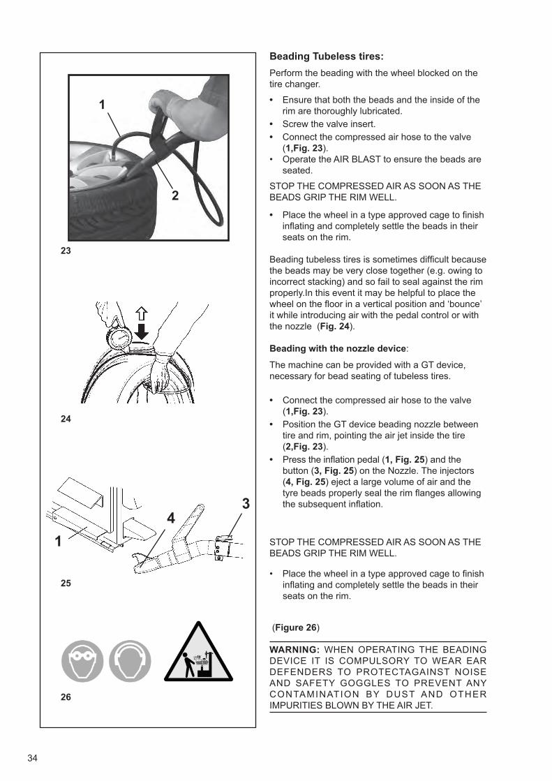
34
24
23
25
34
1
26
1
2
Beading Tubeless tires:
Perform the beading with the wheel blocked on the tire changer.
• Ensure that both the beads and the inside of therim are thoroughly lubricated.
• Screw the valve insert.
• Connect the compressed air hose to the valve(1,Fig. 23).
• Operate the AIR BLAST to ensure the beads areseated.
STOP THE COMPRESSED AIR AS SOON AS THE BEADS GRIP THE RIM WELL.
• Place the wheel in a type approved cage to fi nishinfl ating and completely settle the beads in theirseats on the rim.
Beading tubeless tires is sometimes diffi cult because the beads may be very close together (e.g. owing to incorrect stacking) and so fail to seal against the rim properly.In this event it may be helpful to place the wheel on the fl oor in a vertical position and ‘bounce’ it while introducing air with the pedal control or with the nozzle (Fig. 24).
Beading with the nozzle device:
The machine can be provided with a GT device, necessary for bead seating of tubeless tires.
• Connect the compressed air hose to the valve(1,Fig. 23).
• Position the GT device beading nozzle betweentire and rim, pointing the air jet inside the tire(2,Fig. 23).
• Press the infl ation pedal (1, Fig. 25) and thebutton (3, Fig. 25) on the Nozzle. The injectors(4, Fig. 25) eject a large volume of air and thetyre beads properly seal the rim fl anges allowingthe subsequent infl ation.
STOP THE COMPRESSED AIR AS SOON AS THE BEADS GRIP THE RIM WELL.
• Place the wheel in a type approved cage to fi nishinfl ating and completely settle the beads in theirseats on the rim.
(Figure 26)
WARNING: WHEN OPERATING THE BEADING DEVICE IT IS COMPULSORY TO WEAR EAR DEFENDERS TO PROTECTAGAINST NOISE AND SAFETY GOGGLES TO PREVENT ANY CONTAMINATION BY DUST AND OTHER IMPURITIES BLOWN BY THE AIR JET.
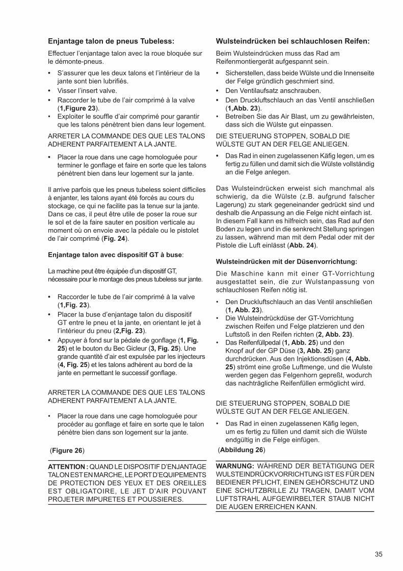
35
Wulsteindrücken bei schlauchlosen Reifen:
Beim Wulsteindrücken muss das Rad am Reifenmontiergerät aufgespannt sein.
• Sicherstellen, dass beide Wülste und die Innenseiteder Felge gründlich geschmiert sind.
• Den Ventilaufsatz anschrauben.
• Den Druckluftschlauch an das Ventil anschließen(1,Abb. 23).
• Betreiben Sie das Air Blast, um zu gewährleisten,dass sich die Wülste gut einpassen.
DIE STEUERUNG STOPPEN, SOBALD DIE WÜLSTE GUT AN DER FELGE ANLIEGEN.
• Das Rad in einen zugelassenen Käfi g legen, um esfertig zu füllen und damit sich die Wülste vollständigan die Felge anlegen.
Das Wulsteindrücken erweist sich manchmal als schwierig, da die Wülste (z.B. aufgrund falscher Lagerung) zu stark gegeneinander gedrückt sind und deshalb die Anpassung an die Felge nicht einfach ist.In diesem Fall kann es hilfreich sein, das Rad auf den Boden zu legen und in die senkrecht Stellung springen zu lassen, während man mit dem Pedal oder mit der Pistole die Luft einlässt (Abb. 24).
Wulsteindrücken mit der Düsenvorrichtung:
Die Maschine kann mit einer GT-Vorrichtung ausgestattet sein, die zur Wulstanpassung von schlauchlosen Reifen nötig ist.
• Den Druckluftschlauch an das Ventil anschließen(1, Abb. 23).
• Die Wulsteindrückdüse der GT-Vorrichtungzwischen Reifen und Felge platzieren und denLuftstoß in den Reifen richten (2, Abb. 23).
• Das Reifenfüllpedal (1, Abb. 25) und denKnopf auf der GP Düse (3, Abb. 25) ganzdurchdrücken. Aus den Injektionsdüsen (4, Abb.25) strömt eine große Luftmenge, und die Wulstewerden gegen das Felgenhorn gepreßt, wodurch das nachträgliche Reifenfüllen ermöglicht wird.
DIE STEUERUNG STOPPEN, SOBALD DIE WÜLSTE GUT AN DER FELGE ANLIEGEN.
• Das Rad in einen zugelassenen Käfi g legen,um es fertig zu füllen und damit sich die Wülsteendgültig in die Felge einfügen.
(Abbildung 26)
WARNUNG: WÄHREND DER BETÄTIGUNG DER WULSTEINDRÜCKVORRICHTUNG IST ES FÜR DEN BEDIENER PFLICHT, EINEN GEHÖRSCHUTZ UND EINE SCHUTZBRILLE ZU TRAGEN, DAMIT VOM LUFTSTRAHL AUFGEWIRBELTER STAUB NICHT DIE AUGEN ERREICHEN KANN.
Enjantage talon de pneus Tubeless:
Effectuer l’enjantage talon avec la roue bloquée sur le démonte-pneus.
• S’assurer que les deux talons et l’intérieur de lajante sont bien lubrifi és.
• Visser l’insert valve.
• Raccorder le tube de l’air comprimé à la valve(1,Figure 23).
• Exploiter le souffl e d’air comprimé pour garantirque les talons pénètrent bien dans leur logement.
ARRETER LA COMMANDE DES QUE LES TALONS ADHERENT PARFAITEMENT A LA JANTE.
• Placer la roue dans une cage homologuée pourterminer le gonfl age et faire en sorte que les talonspénètrent bien dans leur logement sur la jante.
Il arrive parfois que les pneus tubeless soient diffi ciles à enjanter, les talons ayant été forcés au cours du stockage, ce qui ne facilite pas la tenue sur la jante.Dans ce cas, il peut être utile de poser la roue sur le sol et de la faire sauter en position verticale au moment où on envoie avec la pédale ou le pistolet de l’air comprimé (Fig. 24).
Enjantage talon avec dispositif GT à buse:
La machine peut être équipée d’un dispositif GT, nécessaire pour le montage des pneus tubeless sur jante.
• Raccorder le tube de l’air comprimé à la valve(1,Fig. 23).
• Placer la buse d’enjantage talon du dispositifGT entre le pneu et la jante, en orientant le jet àl’intérieur du pneu (2,Fig. 23).
• Appuyer à fond sur la pédale de gonfl age (1, Fig.25) et le bouton du Bec Gicleur (3, Fig. 25). Unegrande quantité d’air est expulsée par les injecteurs(4, Fig. 25) et les talons adhèrent au bord de lajante en permettant le successif gonfl age.
ARRETER LA COMMANDE DES QUE LES TALONS ADHERENT PARFAITEMENT A LA JANTE.
• Placer la roue dans une cage homologuée pourprocéder au gonfl age et faire en sorte que le talonpénètre bien dans son logement sur la jante.
(Figure 26)
ATTENTION : QUAND LE DISPOSITIF D’ENJANTAGE TALON EST EN MARCHE, LE PORT D’EQUIPEMENTS DE PROTECTION DES YEUX ET DES OREILLES EST OBLIGATOIRE, LE JET D’AIR POUVANT PROJETER IMPURETES ET POUSSIERES.
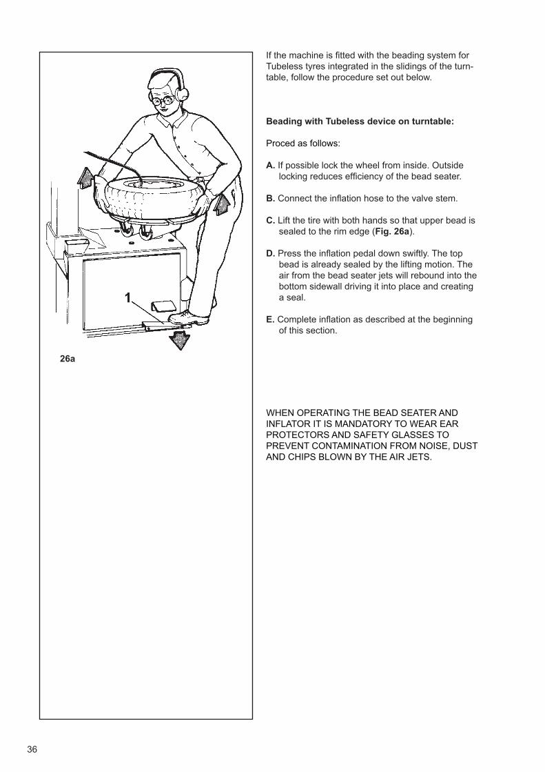
36
26a
If the machine is fi tted with the beading system for Tubeless tyres integrated in the slidings of the turn-table, follow the procedure set out below.
Beading with Tubeless device on turntable:
Proced as follows:
A. If possible lock the wheel from inside. Outside locking reduces effi ciency of the bead seater.
B. Connect the infl ation hose to the valve stem.
C. Lift the tire with both hands so that upper bead is sealed to the rim edge (Fig. 26a).
D. Press the infl ation pedal down swiftly. The top bead is already sealed by the lifting motion. The air from the bead seater jets will rebound into the bottom sidewall driving it into place and creating a seal.
E. Complete infl ation as described at the beginning of this section.
WHEN OPERATING THE BEAD SEATER AND INFLATOR IT IS MANDATORY TO WEAR EAR PROTECTORS AND SAFETY GLASSES TO PREVENT CONTAMINATION FROM NOISE, DUST AND CHIPS BLOWN BY THE AIR JETS.
37
Wenn das System zum Wulsteindrücken für schlau-chlose Reifen bei Ihrer Maschine in die Reiter des Spanntellers integriert ist, befolgen Sie bitte die hier unten angegebene Vorgehensweise.
Wulsteindrücken mit Schlauchlosvorrichtung an der Spannvorrichtung:
Dazu wie folgt vorgehen:
A. Das Rad mit der Spannvorrichtung vorzugsweise von innen spannen (durch eine Felgenaußenspannung wird die Wirksamkeit der Vorrichtung beeinträchtigt).
B. Den Füllschlauch am Ventil befestigen.
C. Den Reifen mit beiden Händen so anheben, daß der obere Wulst gegen das Felgenhorn gedrückt wird (Abb. 26a).
D. Das Reifenfüllpedal mit einer schnellen Bewegung ganz durchdrücken. Aus den Injektionsdüsen an den Spannklauen strömt eine große Luftmenge, und der untere Wulst wird gegen das Felgenhorn gepreßt, wodurch das Reifenfüllen ermöglicht wird.
E. Den Füllvorgang beenden wie eingangs beschrieben.
WUHREND DER BETÄTIGUNG DER FÜLLVORRICHTUNG HATDER BEDIENER UNBEDINGT GEHORSCHUTZ UND EINE SCHUTZBRILLE ZU TRAGEN, DAMIT VOM LUFTSTRAHL AUFGEWIRBELTER STAUB NICHT DIE AUGEN ERREICHEN KANN.
Si la machine présente un système d’enjantage pour pneus Tubeless intégré dans les guides du plateau autocentrant, suivre la procédure indiquée ci-dessous.
Enjantage avec dispositif Tubeless intégré dans l’autocentrant :
Procéder comme il suit:
A. Bloquer la roue sur l’autocentreur par l’intérieur de préférence (le blocage par l’extérieur réduit l’effi cacité du dispositif).
B. Connecter le tuyau de gonfl age à la vanne.
C. Soulever le pneu des deux mains afi n que le talon supérieur s’accroche contre le bord de la jante (Fig. 26a).
D. Appuyer à fond d’une façon rapide sur la pédale de gonfl age. Une grande quantité d’air est expulsée par les injecteurs placés sur les griffes et le talon inférieur adhère au bord de la jante en permettant le gonfl age.
E. Terminer le gonfl age comme décrit au début du paragraphe
PENDANT L’ACTIONNEMENT DU DISPOSITIF DE GONFLAGE IL EST OBLIGATOIRE D’UTILISER DES CASQUES POUR SE PROTÉGER DU BRUIT ET DES LUNETTES DE PROTECTION POUR ÉVITER LA CONTAMINATION PAR LA POUSSIÈRE ET LES IMPURITÉS SOULEVÉES PAR LE JET D’AIR.
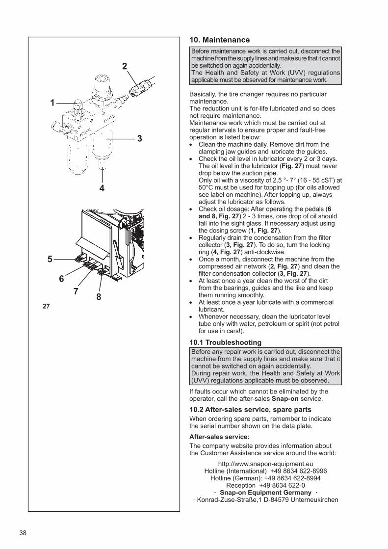
1
4
3
2
38
27
6
7
5
8
10. Maintenance
Before maintenance work is carried out, disconnect the machine from the supply lines and make sure that it cannot be switched on again accidentally.The Health and Safety at Work (UVV) regulations applicable must be observed for maintenance work.
Basically, the tire changer requires no particular maintenance.The reduction unit is for-life lubricated and so does not require maintenance.Maintenance work which must be carried out at regular intervals to ensure proper and fault-free operation is listed below:• Clean the machine daily. Remove dirt from the
clamping jaw guides and lubricate the guides. • Check the oil level in lubricator every 2 or 3 days.
The oil level in the lubricator (Fig. 27) must never drop below the suction pipe.Only oil with a viscosity of 2.5 °- 7° (16 - 55 cST) at 50°C must be used for topping up (for oils allowed see label on machine). After topping up, always adjust the lubricator as follows.
• Check oil dosage: After operating the pedals (6and 8, Fig. 27) 2 - 3 times, one drop of oil should fall into the sight glass. If necessary adjust using the dosing screw (1, Fig. 27).
• Regularly drain the condensation from the fi ltercollector (3, Fig. 27). To do so, turn the locking ring (4, Fig. 27) anti-clockwise.
• Once a month, disconnect the machine from thecompressed air network (2, Fig. 27) and clean the fi lter condensation collector (3, Fig. 27).
• At least once a year clean the worst of the dirtfrom the bearings, guides and the like and keep them running smoothly.
• At least once a year lubricate with a commerciallubricant.
• Whenever necessary, clean the lubricator leveltube only with water, petroleum or spirit (not petrol for use in cars!).
10.1 TroubleshootingBefore any repair work is carried out, disconnect the machine from the supply lines and make sure that it cannot be switched on again accidentally.During repair work, the Health and Safety at Work (UVV) regulations applicable must be observed.
If faults occur which cannot be eliminated by the operator, call the after-sales Snap-on service.
10.2 After-sales service, spare partsWhen ordering spare parts, remember to indicate the serial number shown on the data plate.
After-sales service:
The company website provides information about the Customer Assistance service around the world:
http://www.snapon-equipment.euHotline (International) +49 8634 622-8996
Hotline (German): +49 8634 622-8994Reception +49 8634 622-0
· Snap-on Equipment Germany ·· Konrad-Zuse-Straße,1 D-84579 Unterneukirchen
39
10. WartungBei Wartungsarbeiten ist die Maschine von den Versorgungsnetzen zu trennen und gegen unbeabsichtigtes Einschalten zu sichern.Generell sind bei Wartungsarbeiten die diesbezüglichen Unfallverhütungsvorschriften (UVV) zu beachten.
Die Reifenmontiermaschine bedarf keiner besonderen Wartung.Das Getriebe ist mit einer Dauerschmierstoffüllung versehen und wartungsfrei.Nachfolgend sind die Wartungsarbeiten aufgeführt, die regelmäßig durchgeführt werden müssen, um den ordnungsgemäßen Betrieb und eine störungsfreie und zuverlässige zu gewährleisten:• Maschine täglich reinigen. Dabei Schmutz aus
den Gleitbahnen der Spannklauen entfernen und Gleitbahnen schmieren.
• Alle 2 bis 3 Tage Ölstand im Nebelöler prüfen.Der Nebelöler (Abb.27) muss stets bis über das Saugrohr mit Öl gefüllt sein. Zum Nachfüllen nur ein Öl mit einer Viskosität von 2,5° – 7° (16–55 cST) bei 50 °C verwenden (zulässige Öle siehe Maschinenaufkleber). Nach dem Nachfüllen ist der Nebelöler stets wie folgt einzustellen.
• Öldosierung prüfen. Nach 2 – 3 Schaltvorgängen mitden Pedalen (6 und 8 Abb.27) muss ein Tropfen Öl in die Schaukuppel fallen, gegebenenfalls über die Dosierschraube (1, Abb.27) einstellen.
• Kondensat im Auffangbehälter des Filters (3, Abb.27)regelmäßig ablassen. Hierzu die Nutmutter (4, Abb.27) gegen den Uhrzeigersinn drehen.
• Monatlich die Maschine vom Druckluftnetztrennen (2, Abb.27) und den Kondensat-Auffangbehälter des Filters (3, Abb.27) reinigen.
• Mindestens einmal jährlich Lagerstellen, Gleit- undFührungsbahnen von übermäßig angefallenem Schmutz säubern und gängig halten.
• Mindestens einmal jährlich mit einem handelsüblichenSchmierfett schmieren: Gelenkbolzen, Lagerstellen, Gleitbahnen sowie die Spanneinrichtung.
• Das Schauglas des Nebelölers bei Bedarf nur mit Wasser,Petroleum oder alkohol (kein Kfz-Kraftstoff) reinigen.
10.1 StörungenBei Reparaturarbeiten ist die Maschine von den Versorgungsnetzen zu trennen und gegen unbeabsichtigtes Einschalten zu sichern.Generell sind bei Reparaturarbeiten die diesbezüglichen Unfallverhütungsvorschriften (UVV) zu beachten.
Sollten Störungen auftreten, welche vom Betreiber nicht zu beheben sind, den Snap-on-Kundendienst anfordern.
10.2 Kundendienst, ErsatzteileBei Bestellung von Ersatzteilen immer die Maschinennummer (Typenschild) angeben.
Kundendienst in der Bundesrepublik:
Auf der Internet-Seite sind Informationen über den Kundendienst in den verschiedenen Ländern verfügbar:
http://www.snapon-equipment.euHotline (International) +49 8634 622-8996
Hotline (German): +49 8634 622-8994Reception +49 8634 622-0
· Snap-on Equipment Germany ·· Konrad-Zuse-Straße,1 D-84579 Unterneukirchen
10. EntretienAvant l’entretien, débrancher la machine de toutes les lignes d’alimentation en énergie et la verrouiller pour éviter une mise en marche accidentelle.En général, pour les travaux d’entretien, respecter la réglementation en matière de prévention des accidents du travail.
En principe, le démonte-pneus n’a pas besoin d’un entretien particulier.Les engrenages sont graissés à vie et ne requièrent aucun type d’entretien.Voici la liste des travaux d’entretien qui doivent être effectués régulièrement pour assurer un fonctionnement impeccable:• Nettoyer la machine chaque jour. Nettoyer les glissières
des mors de serrage et lubrifi er les glissières. • Vérifi er le niveau d’huile dans le lubrifi cateur tous les 2 ou
3 jours. Le lubrifi cateur (Fig. 27) doit toujours être rempli d’huile au-delà du tube d’aspiration.Pour l’appoint, n’utiliser qu’une huile d’une viscosité de 2,5° - 7° E (16 - 55 cST) à 50 °C (pour les huiles préconisées, voir l’étiquette adhésive sur la machine). Après l’appoint, toujours régler le lubrifi cateur comme suit.
• Vérifi er le dosage de l’huile. Après avoir actionnéles pédales (6 et 8, Fig. 27) deux à trois coups, une gotte d’huile doit tomber dans le verre indicateur; sinon, régler la vis de dosage (1, Fig. 27).
• Purger périodiquement le collecteur de condensatdu fi ltre (3, Fig. 27) en tournant la bague (4, Fig. 27) dans le sens inverse des aiguilles d’une montre.
• Chaque mois, débrancher la machine du réseaupneumatique (2, Fig. 27) et nettoyer le collecteur de condensat du fi ltre (3, Fig. 27).
• Au moins une fois par an, débarrasser les coussinets,les glissières etc. des incrustations pour améliorer le roulement.
• Au moins une fois par an, lubrifi er avec une graisseen vente dans le commerce.
• Nettoyer le tube de niveau du lubrificateur, le cas échéant.Avec de l’eau, du pétrole ou de l’essence détergente (ne jamais utiliser de l’essence pour voitures!).
10.1 DéfautsAvant une réparation, débrancher la machine de toutes les lignes d’alimentation en énergie et la verrouiller pour éviter une mise en marche accidentelle. En général, pour les réparations, respecter la réglementation en matière de prévention des accidents du travail.
Si la panne ne peut être réparée par l’opérateur, faire appel au service d’assistance Snap-on.
10.2 Service après vente, pièces détachées
Dans une commande de pièces détachées, toujours préciser le numéro de série indiqué sur la plaque signalétique.
Service après vente:
Le site Internet fournit des informations concernant le service après-vente dans les différents pays:
http://www.snapon-equipment.euHotline (International) +49 8634 622-8996
Hotline (German): +49 8634 622-8994Reception +49 8634 622-0
· Snap-on Equipment Germany ·Konrad-Zuse-Straße,1 D-84579 Unterneukirchen
40
10” - 22”12” - 24”15” - 23”
1”-15”/40-392 mm3 - 12”
230 VAC, 1Ph, 50/60Hz, 16A200VAC, 1Ph, 50-60Hz, 20A
1000 Nm0,9 kW
7/18
7” - 13”17.5””
1000 mm
8–12 bar
12060 N250–330 l70 dB (A)
88,7 dB (A)
1700 mm1160 mm1850 mm
220 kg
WHITE MINERAL OIL 15ONDINA OIL 15ENERGOL WT3LOBELIA SB 15
MARCOL 82
11. Technical specifi cations
(Basic version)External clamping rangeInternal clamping rangewith motorcycle jawsBead breaking range:Rim width
- Std Electrical connections -(Standard)(Japan) TorqueMotor powerTurntable speed (rpm)
- Wheels specifi cation - with special jaws for trolley and mini wheelswith special jaws for light-truck wheels Max. wheel diameter
Compressed air supplyBead breaker force at 10 bar pressureand 200 mm arm openingAir consumption per wheel, approx. Sound levelSound level when infl ating with air jet system
- Machine dimensions -Max. depth (including space for tower tilting) Max. widthMax. heightApprox. weight
- Appropriate oil for oiler -TAMOIL:SHELL :BP :TOTAL :ESSO :
STC5325
41
10” - 22”12” - 24”15” - 23”
1”-15”/40-392 mm3 - 12”
230 VAC, 1Ph, 50/60Hz, 16A200VAC, 1Ph, 50-60Hz, 20A
1000 Nm0,9 kW
7/18
7” - 13”17.5””
1000 mm
8–12 bar
12060 N250–330 l70 dB (A)
88,7 dB (A)
1700 mm1160 mm1850 mm
220 kg
WHITE MINERAL OIL 15ONDINA OIL 15ENERGOL WT3LOBELIA SB 15
MARCOL 82
10” - 22”12” - 24”15” - 23”
1”-15”/40-392 mm3 - 12”
230 VAC, 1Ph, 50/60Hz, 16A200VAC, 1Ph, 50-60Hz, 20A
1000 Nm0,9 kW
7/18
7” - 13”17.5””
1000 mm
8–12 bar
12060 N250–330 l70 dB (A)
88,7 dB (A)
1700 mm1160 mm1850 mm
220 kg
WHITE MINERAL OIL 15ONDINA OIL 15ENERGOL WT3LOBELIA SB 15
MARCOL 82
11. Technische Daten
(Basisversion)AußenspannungsbereichInnenspannungsbereichmit MotorradspannklauenAbdrückbereichFelgenbreite
- Elektroanschluss -(Standard)(Japan) AntriebsmomentMotorleistungArbeitsgeschwindigkeit des Spanntellers (U/m)
- Räder-Spezifi kation -mit Sonderspannklauen für Karren-und Kleinrädermit Sonderspannklauen für LLkw-Räder Maximaler Raddurchmesser
LuftanschlussAbdrückkraft bei 10 bar Pressdruckund 200 mm ArmöffnungLuftbedarf pro Rad, etwaGeräuschemissionGeräuschemission bei Befüllung mit Luftfüllstoß
- Maschinenabmessungen -Tiefe max. (mit Platz zum Kippen der Säule) Breite max. Höhe max. Gewicht ca.
- Für den Filter/Luftöler empfohlene Öle -TAMOIL:SHELL :BP :TOTAL :ESSO :
11. Données techniques
(Version base)Gamme de serrage de l’extérieurGamme de serrage de l’intérieuravec mors pour roues de motoGamme de décollage:Largeur jantes
- Alimentation électrique -(Standard)(Japan) Couple d’entraînementPuissance du moteurVitesse de service du mandrin (t/min)
- Spécifi cation Roues -avec mors pour roues mini et de chariotsavec mors spéciaux pour camionnettes Diamètre roue maxi
Air compriméPression du décolleur à 10 barset ouverture du bras de 200 mmConsommation d’air par roue, env. Niveau sonoreNiveau sonore pendant le gonfl age avecun système de gonfl age à jet d’air
- Dimensions de la machine -Profondeur maxi - (y compris l’espace pour l’inclinai-son du montant) Largeur maxiHauteur maxiPoids environ
- Huiles conseillées pour fi ltre/ huileur -TAMOIL:SHELL :BP :TOTAL :ESSO :
STC5325STC5325
42
12. Disposing of the unit
When you decide to get rid of your unit, contact your reseller for a quote or for the regulations on disposal which apply to the unit.
12.1 Instructions for disposalFor waste electrical and electronic equipment
At the time of disposal, at the end of the lifetime of this equipment, you must:
1. NOT dispose of the equipment as municipalwaste and separate collection is mandatory.
2. Ask the retailer about collection points au-thorised for regular disposal.
3. Stick to the standards for correct wastemanagement, to prevent potential effects on the environment and human health.
This symbol indicates that separate collection of wa-ste electrical and electronic equipment is mandatory for scrapping.
43
12. Entsorgung
Wenn das Gerät entsorgt werden soll, setzen Sie sich bitte mit Ihrem Händler in Verbindung und fra-gen Sie ihn nach einem Preisangebot bzw. nach den Bestimmungen zur Entsorgung des Geräts.
12.1 Anleitung zur EntsorgungFür elektrische und elektronische Geräte
Für die Entsorgung des Geräts am Ende seiner Le-bensdauer gelten folgende Vorschriften:
1. Das Gerät darf NICHT als Hausmüll entsorgt wer-den, sondern muss dem Sondermüll zugeführt werden.
2. Informieren Sie sich bei Ihrem Händler überdie Müllsammelzentren, die zur ordnungsgemäßen Entsorgung befugt sind.
3. Befolgen Sie die Richtlinien für dieordnungsgemäße Behandlung von Müll, um mögli-che Gefahren für die Umwelt und für die Gesundheit zu vermeiden.
Dieses Symbol zeigt an, dass es Pfl icht ist, elektri-sche und elektronische Geräte nach der Verschrot-tung dem Sondermüll zuzuführen.
12. Vente
Lorsque vous décidez de vendre la machine, contactez votre revendeur pour obtenir le prix offert ou les règle-ments appropriés pour la revente de la machine.
12.1 Consignes de démolitionInstructions d’equipements electriques et elec-troniques
Au moment de la mise à la décharge, à la fi n de la vie de cet équipement, il est obligatoire de :
1. NE PAS ELIMINER cet appareillage commedéchet urbain mais d’effectuer le tri sélectif de ses composants.
2. S’informer auprès du revendeur sur les cen-tres de collecte autorisés au tri et au traitement de ce type de déchet.
3. Respecter les normes sur la gestion desdéchets pour éviter tout risque probable de nuisan-ces à l’environnement et à la santé des personnes.
Ce symbole indique l’obligation d’effectuer le tri sélectif des appareils électriques et électroniques au moment de sa mise à la décharge.
Manufacturing Facility
Snap-on Equipment S.r.L.
Via Provinciale per Carpi 33,
42015 Correggio (R.E.), Italy
Tel.: ++39 (0)522 733480
Fax: ++39 (0)522 733479
Tech
nic
al m
odifi
catio
ns
rese
rved.
copyright 2016
GB
FR
DE
SO
E D
igital C
ode: O
M_
SU
N S
TC
5325_
16-0
5_
EN
-FR
-DE
_A
_Z
EE
WH
118A
03
Notice: The information contained in this document is subject to change without notice. SUN makes no war-
ranty with regard to present documentation. SUN shall not be liable for errors contained herein or for in-
cidental consequential damages in connection with furnishings, performance, or use of this material.