p/n 030-1370 a 5 incandescent / halogen 120 v dimmer 1 · en raccordant des fils, respecter les...
TRANSCRIPT
Lutron Electronics Co., Inc.7200 Suter RoadCoopersburg, PA 18036-1299, U.S.A.Made and printed in U.S.A. 10/10 P/N 030-1370 Rev. A
ON
OFF
ON
OFF
ON
OFF
Backwired:Insert screwdriver.Pull wire out.
Screw Terminals:Turn screws toloosen.
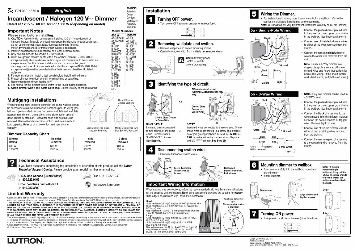
SINGLE-POLE:Insulated wires connectedto two screws of the samecolor. Replace with aSINGLE-POLE dimmer.See Step 5a.
OR
3-WAY:Insulated wires connected to three screws. One ofthese wires is connected to a screw of a different-color (not green) or labeled COMMON. MARK orTAG this wire to identify it when wiring. Replacewith a 3-WAY dimmer. See Step 5b.
Tag
Different-colored screw(Common). Actual location mayvary.
ORGround (BareCopper orGreen Wire)
Ground (Bare Copperor Green Wire)
ON
OFF
ON
OFF
ON
OFF
Incandescent / Halogen 120 V DimmerRated at 120 V 60 Hz 600 or 1000 W (depending on model).
sedis 2edis 1sedis oNremmiDdevomerdevomerdevomergnitaR
W004 W005 W006 W006 W056 W008 W0001W0001
Limited WarrantyLutron will, at its option, repair or replace any unit that is defective in materials or manufacture within one year after purchase. For warranty service,return unit to place of purchase or mail to Lutron at 7200 Suter Rd., Coopersburg, PA 18036-1299, postage pre-paid.THIS WARRANTY IS IN LIEU OF ALL OTHER EXPRESS WARRANTIES, AND THE IMPLIED WARRANTY OF MERCHANTABILITY ISLIMITED TO ONE YEAR FROM PURCHASE. THIS WARRANTY DOES NOT COVER THE COST OF INSTALLATION, REMOVAL ORREINSTALLATION, OR DAMAGE RESULTING FROM MISUSE, ABUSE, OR DAMAGE FROM IMPROPER WIRING OR INSTALLATION.THIS WARRANTY DOES NOT COVER INCIDENTAL OR CONSEQUENTIAL DAMAGES. LUTRON’S LIABILITY ON ANY CLAIM FORDAMAGES ARISING OUT OF OR IN CONNECTION WITH THE MANUFACTURE, SALE, INSTALLATION, DELIVERY, OR USE OF THE UNITSHALL NEVER EXCEED THE PURCHASE PRICE OF THE UNIT.This warranty gives you specific legal rights, and you may have other rights which vary from state to state. Some states do not allow the exclusionor limitation of incidental or consequential damages, or limitation on how long an implied warranty may last, so the above limitations may not applyto you. Lutron, Ariadni, Diva, Glyder, and Skylark are registered trademarks and Luméa2 and Rotary are trademarks ofLutron Electronics Co., Inc. NEC is a registered trademark of the National Fire Protection Association, Quincy, Massachusetts.© 2010 Lutron Electronics Co., Inc.
Important Wiring Information
Twist wire connectortight.
Be sure no bare wireis exposed.
When making wire connections, follow the recommended strip lengths and combinationsfor the supplied wire connectors. Note: Wire connectors provided are suitable for copperwire only. For aluminum wire, consult an electrician.
SmallLarge
? Technical AssistanceIf you have questions concerning the installation or operation of this product, call the LutronTechnical Support Center. Please provide exact model number when calling.
U.S.A. and Canada (24 hrs/7days)+1.800.523.9466Other countries 8am – 8pm ET+1.610.282.3800
Fax: +1.610.282.1243
http://www.lutron.com
Installation
1 Turning OFF power.• Turn power OFF at circuit breaker (or remove fuse).
2 Removing wallplate and switch.• Remove wallplate and switch mounting screws.• Carefully remove switch from wall (do not remove wires).
Caution: Verify poweris OFF to switchbefore proceeding.
3 Identifying the type of circuit.
4 Disconnecting switch wires.• Carefully disconnect switch wires.
7 Turning ON power.• Turn power ON at circuit breaker (or replace fuse).
6 Mounting dimmer to wallbox.• Form wires carefully into the wallbox, mount and
align dimmer.• Install wallplate.
• NOTE: Only one dimmer can be used ina 3-WAY circuit.
• Connect the green dimmer ground wireto the green or bare copper ground wirein the wallbox. (See Important Note 4.)
• Connect the black dimmer wire to thewire removed from the different-coloredscrew on the switch (marked or taggedwire). Remove tag from wire.
• Connect one of the red dimmer wires toeither of the remaining wires removedfrom the switch.
• Connect the remaining red dimmer wireto the remaining wire removed from theswitch.
• Connect the green dimmer ground wireto the green or bare copper ground wirein the wallbox. (See Important Note 4.)
• Connect one of the black dimmer wiresto either of the wires removed from theswitch.
• Connect the remaining black dimmerwire to the other wire removed from theswitch.
Note: To use a 3-Way dimmer in asingle-pole application, cap off one ofthe red wires and follow instructions forsingle-pole wiring. (If the on/off switchworks backwards, switch the red wires.)
5 Wiring the Dimmer.• For installations involving more than one control in a wallbox, refer to the
section on Multigang Installations before beginning.Note: Wire location will vary by product. Reference wires by color, not location.
5a - Single-Pole Wiring
120 V60 Hz
Black Black
Green
Ground Light
Black
Green
Light
Red
Red
120 V60 Hz Ground
Dimmer 3-Way Switch
5b - 3-Way Wiring
GreenGround
Black
Dimmer Capacity Chart
Multigang InstallationsWhen installing more than one control in the same wallbox, it maybe necessary to remove all inner side sections prior to wiring (seebelow). If pre-installed, remove the Lutron wallplate and wallplateadapter from dimmer. Using pliers, bend side section up anddown until they break off. Repeat for each side section to beremoved. Removal of dimmer side sections reduces maximumload capacity. Refer to chart below for maximum dimmercapacity.
P/N 030-1370 a
Do Not RemoveOutside Sections
Each Control Has InsideSections Removed
Middle Control Has TwoSide Sections Removed
Start screws.
Align dimmer andtighten screws.
Note: To install atraditional stylewallplate, firmly pull theGlyder or Rotary knob toremove it. Install thewallplate and re-attachthe knob.
Glyder
Rotary
Models:Ariadni®Diva®
Glyder®
Luméa2TM
RotaryTM
Skylark®
Green GroundRed
Black Tag
Small:Strip insulation 3/8 in (10 mm) for 14 AWG (1.5 mm²) wireStrip insulation 1/2 in (13 mm) for 16 or 18 AWG (1.0 or 0.75 mm²) wireUse to join one 14 AWG (1.5 mm²) supply wire with one 16 or 18 AWG (1.0 or 0.75 mm²) control wire.Large:Strip insulation 1/2 in (13 mm) for 10, 12 or 14 AWG(4, 2.5, or 1.5 mm²) wireStrip insulation 5/8 in (16 mm) for 16 or 18 AWG(1.0 or 0.75 mm²) wireUse to join one or two 12 or 14 AWG (2.5 or 1.5 mm²) supply wires with one 10, 12, 14, 16, or 18 AWG(4, 2.5, 1.5, 1.0, or 0.75 mm²) control wire.
English
Important NotesPlease read before installing.1. CAUTION: Use only with permanently-installed 120 V incandescent or
halogen fixtures. To avoid overheating andpossible damage to other equipment, do not use to control receptacles, fluorescent lighting fixtures, motor-drivenappliances, or transformer-supplied appliances.
2. Install in accordance with all national and local electrical codes.3. Only one dimmer can be used in a 3-way circuit.4. When no “ground means” exists within the wallbox, then NEC® 2002 404-9
exception to (b) allows a dimmer without aground connection, to be installed as a replacement. For this type of installation, cap or remove the green dimmerground wire. A dimmer installed under this exception (NEC® 2002 404-9 exception to (b)) must be provided with aplastic, noncombustible, UL listed wallplate.
5. For new installations, install a test switch before installing the dimmer.6. Protect dimmer from dust and dirt when painting or spackling.7. Recommended minimum load is 40 W8. It is normal for the dimmer to feel warm to the touch during operation.9. Clean dimmer with a soft damp cloth only. Do not use any chemical cleaners.
Model Numbers:600 WAY-600PNLHAY-603PNLHA43D-600PD-603PDNG-600PDNG-603PGL-600GL-600PGL-600PHGL-603PGL-603PHLT-603PHS-600S-600HS-600PS-600PRS-603PS-603PRS2-L
1000 WAY-10PAY-103PAY-103PNLGL-10PGL-1000GL-1000HGL-103PLT-103PHS-10PS-10PHS-10PRS-1000S-103P

120 V60 Hz
Lutron Electronics Co., Inc.7200 Suter RoadCoopersburg, PA 18036-1299, U.S.A.Fabriqué et imprimé aux USA. 10/10 No de pièce 030-1370 Rév. A
ON
OFF
ON
OFF
ON
OFF
Fils à l’arrière :Insérer untournevis.Tirer sur le fil pourle sortir.
Bornes à vis :Tourner les vispour les desserrer.
UNIPOLAIRE :Les fils recouverts sontraccordés à deux vis de lamême couleur. Remplacer parun gradateur UNIPOLAIRE.Voir l’étape 5a.
OU
3 VOIES :Les fils recouverts sont raccordés à trois vis. L’un deces fils est connecté à une vis de couleur différente(pas verte) ou étiquetée NEUTRE. MARQUER ouÉTIQUETER ce fil pour l’identifier lors du câblage.Remplacer par un gradateur 3 VOIES. Voir l’étape 5b.
Étiquette
Vis de couleur différente(neutre). Son emplacement peutdifférer de l’illustration.
OUMise à la terre (filde cuivre dénudéou fil vert)
Mise à la terre (fil decuivre dénudé ou fil vert)
ON
OFF
ON
OFF
ON
OFF
Gradateur à incandescence / halogène 120 VPuissance nominale de 120 V 60 Hz 600 ou 1 000 W (selon le modèle).
sétôc 2étôc 1étôc nucuAelanimon ecnassiuPsévelneévelneévelneruetadarg ud
W 004 W 005 W 006W 006 W 056 W 008 W 0001W 0001
Garantie limitéeLutron, à son choix, réparera ou remplacera toute unité présentant des défauts de matériaux ou de main-d’œuvre pendant une durée de un (1) an à compter de la date d’achat.Pour le service sous garantie, retourner l’unité chez le détaillant ou l’envoyer par la poste dans un colis affranchi à l’adresse suivante : Lutron, 7200 Suter Rd., Coopersburg,PA 18036-1299.LA PRÉSENTE GARANTIE REMPLACE TOUTE AUTRE GARANTIE EXPRESSE, ET LA GARANTIE IMPLICITE DE QUALITÉ MARCHANDE SE LIMITE À UN AN ÀCOMPTER DE LA DATE D’ACHAT. LA PRÉSENTE GARANTIE NE COUVRE PAS LES COÛTS D’INSTALLATION, DE DÉPOSE OU DE RÉINSTALLATION OU LESDOMMAGES RÉSULTANT D’UN MAUVAIS USAGE OU D’UN USAGE ABUSIF, NI LES DOMMAGES RÉSULTANT D’UNE MAUVAISE INSTALLATION OU D’UNRACCORDEMENT INADÉQUAT DES FILS. LA PRÉSENTE GARANTIE NE COUVRE PAS LES DOMMAGES INDIRECTS OU CONSÉCUTIFS. LA RESPONSABILITÉ DELUTRON CONCERNANT TOUTE RÉCLAMATION POUR DOMMAGES DÉCOULANT DE (OU RELIÉS À) LA FABRICATION, LA VENTE, L’INSTALLATION, LA LIVRAISONOU L’UTILISATION DE L’UNITÉ NE POURRA EN AUCUN CAS DÉPASSER LE PRIX D’ACHAT DE L’UNITÉ.La présente garantie accorde des droits légaux précis, et certains autres droits variant selon l’état ou la province de résidence. Certains états ou provinces ne permettent pasl’exclusion ou la restriction des dommages indirects ou consécutifs, ou l’imposition d’une limite de temps sur la garantie implicite. Les restrictions mentionnées ci-dessuspourraient donc ne pas s’appliquer. Lutron, Ariadni, Diva, Glyder, et Skylark sont des marques de commercedéposées et Luméa2 et Rotary sont des marques de Lutron Electronics Co., Inc. NEC est une marque de commerce de National Fire Protection Association, Quincy,Massachusetts. © 2010 Lutron Electronics Co., Inc.
Informations importantes sur le câblage
Visser le capuchon deconnexion serré.
Voir à ce qu’aucunfil dénudé ne soit
exposé.
En raccordant des fils, respecter les longueurs et les combinaisons de dénudation recommandéespour les capuchons de connexion fournis. Remarque : N’utiliser que des fils de cuivre avec lescapuchons de connexion fournis. Pour les fils d’aluminium, s’adresser à un électricien.
Petit Gros
? Assistance techniqueEn cas de question reliée à l’installation ou au fonctionnement de ce produit, appeler leCentre de soutien technique Lutron. Le numéro de modèle exact est requis au moment de l’appel.
Installation
1 Coupure de l’alimentation électrique.• Couper l’alimentation au disjoncteur (ou retirer le fusible).
2 Dépose de la plaque murale et de l’interrupteur.• Enlever la plaque murale et les vis de montage de l’interrupteur.• Retirer délicatement l’interrupteur du mur (ne pas enlever les fils).
Mise en garde :S’assurer quel’alimentationélectrique est coupéeavant de commencer.
3 Identification du type de circuit.
4 Débranchement des fils de l’interrupteur.• Débrancher les fils de l’interrupteur avec soin.
7 Mise sous tension.• Mettre le circuit sous tension au disjoncteur de
circuit (ou replacer le fusible).
6 Montage du gradateur dans la boîte murale.• Replier les fils soigneusement dans la boîte murale,
monter et aligner le gradateur.• Installer la plaque murale.
• REMARQUE : Un seul gradateur peut êtreutilisé dans un circuit à 3 voies.
• Raccorder le fil de mise à la terre vert dugradateur au fil vert ou en cuivre dénudéde la boîte murale. (Voir la remarqueimportante 4.)
• Raccorder le fil noir du gradateur au filenlevé de la vis de couleur différente del’interrupteur (fil marqué ou étiqueté).Enlever l’étiquette du fil.
• Raccorder un des fils rouges dugradateur à l’un ou l’autre des fils restantsenlevés de l’interrupteur.
• Raccorder le fil rouge restant dugradateur au fil restant enlevé del’interrupteur.
• Raccorder le fil de mise à la terre vert dugradateur au fil vert ou en cuivre dénudé de laboîte murale. (Voir la remarque importante 4.)
• Raccorder l’un des fils noirs du gradateur àl’un ou l’autre des fils enlevés de l’interrupteur.
• Raccorder le fil noir restant du gradateur àl’autre fil enlevé de l’interrupteur.
Remarque : Pour utiliser un gradateur à 3voies dans un secteur unipolaire, mettre uncapuchon sur l’un des fils rouges et suivre lesinstructions d’installation pour un câblageunipolaire. (Si le fonctionnement del’interrupteur marche-arrêt est inversé,échanger les fils rouges.)
5 Câblage du gradateur.• Pour les installations comportant plus d’un gradateur dans une même boîte murale,
consulter la section «Installation de gradateurs multiples» avant de commencer.Remarque : L’emplacement des fils peut varier selon le produit. Associer les fils parcouleur, et non par emplacement.
5a - Câblage unipolaire
120 V60 Hz
Noir Noir
Vert
Mise à laterre Appareil
Noir
Vert
Appareil
Rouge
Rouge
Mise à laterre
Gradateur Interrupteurà 3 voies
5b - Câblage à 3 voies
VertMise à la terre
Noir
Mise à la terre
Noir Étiquette
Vert
Tableau des capacités du gradateur
Installation d’interrupteurs multiplesLors de l’installation de plus d’un gradateur dans la même boîte murale, ilpeut être nécessaire d’enlever toutes les sections latérales intérieuresavant de faire le câblage (voir ci-dessous). Si elle est pré-installée,enlever la plaque murale Lutron ainsi que l’adaptateur de plaque dugradateur. Avec des pinces, replier la section latérale de haut en basjusqu’à ce qu’elle se sépare. Répéter pour chacune des sections latéralesà enlever. La dépose des sections latérales du gradateur a pour effet deréduire la capacité de charge maximale. Consulter le tableau ci-dessouspour connaître la capacité maximale du gradateur.
P/N 030-1370 a Français
U.S.A. et Canada (24h sur 24 / 7jrs sur 7)+1.800.523.9466Autres pays : 8h – 20h, heure de l’Est+1.610.282.3800
Télécopieur +1.610.282.1243
http://www.lutron.com
Rouge
Modèles :Ariadni®Diva®
Glyder®
Luméa2TM
RotaryTM
Skylark®
Ne pas retirer lessections extérieures
Les sections intérieures dechaque gradateur sont
enlevées
Les deux sections latéralesdu gradateur mitoyen sont
enlevées
Visser légèrementles vis
Aligner le gradateur etbien visser en place.
Note: Pour installer laplaque murale de styletraditionnel, enlever lebouton du Glyder ou Rotaryen tirant dessus. Installerensuite la plaque muralepuis replacer le bouton.
Glyder
Rotary
Petit :Dénuder la gaine d’isolation de 10 mm (3/8 po) pour les fils de calibre 1,5 mm² (14 AWG).Dénuder la gaine d’isolation de 13 mm (1/2 po) pour les fils de calibre 1,0 ou 0,75 mm² (16 ou 18 AWG).Utiliser pour joindre un fil d’alimentation de calibre 1,5 mm²(14 AWG) avecun fil de commande de calibre 1,0 ou 0,75 mm²(16 ou 18 AWG).Gros :Dénuder la gaine d’isolation de 13 mm (1/2 po) pour les fils de calibre 4; 2,5; ou 1,5 mm² (10, 12 ou 14 AWG).Dénuder la gaine d’isolation de 16 mm (5/8 po) pour les fils de calibre 1,0 ou 0,75 mm² (16 ou 18 AWG).Utiliser pour joindre un ou deux fils d’alimentation de calibre2,5 ou 1,5 mm² (12 ou 14 AWG) avec un fil de commande d’intensité decalibre 4; 2,5; 1,5; 1,0 ou 0,75 mm² (10, 12, 14, 16 ou 18 AWG).
Numéros de Modèle600 WAY-600PNLHAY-603PNLHA43D-600PD-603PDNG-600PDNG-603PGL-600GL-600PGL-600PHGL-603PGL-603PHLT-603PHS-600S-600HS-600PS-600PRS-603PS-603PRS2-L
1000 WAY-10PAY-103PAY-103PNLGL-10PGL-1000GL-1000HGL-103PLT-103PHS-10PS-10PHS-10PRS-1000S-103P
Remarques importantesVeuillez lire avant de procéder à l’installation.1. MISE EN GARDE : N’utiliser qu’avec des appareils d’éclairage incandescents ou
halogènes de 120 V installés enpermanence. Pour éviter la surchauffe et d’éventuels dommages à d’autres équipements, ne pas utiliser ce dispositifpour commander l’intensité des prises de courant, des luminaires à tube fluorescent, des appareils à moteur électriqueou des appareils alimentés par transformateur.
2. L’installer en respectant tous les codes d’électricité nationaux et locaux.3. Un seul gradateur peut être utilisé dans un circuit à 3 voies.4. Lorsqu’il n’existe aucun fil de mise à la terre dans la boîte murale, le code NEC® 2002
404-9, à l’exception duparagraphe (b), permet l’installation d’un gradateur non raccordé avec un fil de mise à la terre en tant que dispositif deremplacement. Pour ce type d’installation, couvrir le fil vert de mise à la terre d’un capuchon ou le retirer du gradateur.L’installation d’un gradateur en vertu de cette exception (code NEC® 2002 404-9 à l’exception du paragraphe (b)) doitinclure une plaque murale en plastique incombustible, homologuée UL.
5. Pour les nouvelles installations, installer un interrupteur d’essai avant de faire la pose du gradateur.
6. Protégez le gradateur de la poussière et de la saleté lorsque vous peignez ou rebouchez.7. La charge minimale recommandée est de 40 W.8. Il est normal de sentir une chaleur au toucher du gradateur intelligent lorsqu’il fonctionne.9. Nettoyer le gradateur avec un chiffon doux et humide seulement. Ne pas utiliser de
nettoyants chimiques.