plc-1710, 1710-7, 1760, 1760-7, 1760l engineer’s …semsi.com.mx/manuales/juki/plc-1700...
TRANSCRIPT
40040656No.E372-01
ENGINEER’S MANUAL
Post-bed, Unison-feed, Lockstitch Machine
PLC-1700 Series
®
PLC-1710, 1710-7, 1760, 1760-7, 1760L

Introduction
This Engineer’s Manual is for technical service engineers. In the Adjusting instruction manual for the maintenance
engineers of sewing machine and sewing workers in a sewing factory, how to operate a sewing machine is also
described in detail. However, in this manual, [Adjustment Procedure]. [Results of Value change for Adjustment],
and the roles of each component are described: these are not included in the Adjusting instructions manual.
When maintenance is performed for our sewing machines, refer not only to this manual, but also to the Adjusting
instructions / illustrated parts list.
In regard to the thread trimming machine motor, please refer to the Instruction Manual for the SC-510 motor and
the Service Manual, separately furnished. In regard to the control panel also, please refer to the Instruction Manual
for the control panel.
This Engineer’s Manual describes the basic adjusting values as the reference values in the first page, and the
observed events caused by sewing and mechanical faults as the [Results of Value Change for Adjustment], and
[Adjustment Procedure ] in the second page.

CONTENTS
1. Specifications ........................................................................................................ 1
2. Model Numbering system ..................................................................................... 2(1) PLC-1710 ................................................................................................................................... 2(2) PLC-1760 ................................................................................................................................... 3(3) PLC-1710-7 ................................................................................................................................ 4(4) PLC-1760-7 ................................................................................................................................ 5
3. Standard adjustment .............................................................................................. 6(1) Needle entry position ............................................................................................................. 6(2) Adjustment of the feed dog position .................................................................................... 8(3) Clearance between the throat plate and the inner hook clamp section .......................... 10(4) Height of the feed dog .......................................................................................................... 12(5) Timing between the needle and the hook (Except for PLC-1760L) .................................. 14(6) Timing between the needle and the hook (PLC-1760L) .................................................... 16(7) Adjusting the inner hook guide ........................................................................................... 18(8) Lifting amount of presser .................................................................................................... 20
1) Presser lifter lever ............................................................................................................ 202) Using a knee lifter (PLC-1710, 1760, 1760L)................................................................... 203) Auto presser lifter (PLC-1710-7, 1760-7) ........................................................................ 20
(9) Timing belt setup .................................................................................................................. 22(10) Feed motion .......................................................................................................................... 24
1) Alternate vertical amount ................................................................................................ 242) Alternate momentum amount .......................................................................................... 26
(11) Feed cam phase .................................................................................................................... 281) Horizontal feed cam phase .............................................................................................. 282) Top feed cam phase ......................................................................................................... 303) Vertical feed cam phase ................................................................................................... 32
(12) Needle motion ...................................................................................................................... 34(13) Normal and reverse stitch length ....................................................................................... 34(14) Balance ................................................................................................................................. 36(15) Position of reverse feed lever ............................................................................................. 38(16) Safety mechanism ................................................................................................................ 40(17) Reverse feed cylinder and condensation cylinder ........................................................... 42
∗∗∗∗∗ (18) Thread trimming device (PLC-1710-7, 1760-7) .................................................................. 441) Adjusting the height of the moving knife ....................................................................... 442) Adjusting the position of the counter knife and knife pressure .................................. 463) Adjusting the clamp spring ............................................................................................. 464) Adjust the thread trimming cam position ...................................................................... 485) Timing adjustment for the thread trimming cam ........................................................... 506) Connection of the rocking arm and the thread trimmer roller arm.............................. 507) Thread trimming solenoid ............................................................................................... 528) Adjusting the position of the moving knife (Right) (PLC-1710-7, 1760-7) ................... 529) Adjusting the position of the moving knife (Left) (PLC-1760-7 only) .......................... 54
(19) Alternate vertical dial (PLC-1710-7, 1760-7) ....................................................................... 561) Mounting position of the alternate vertical amount detector switch........................... 56
(Caution) ∗∗∗∗∗ Adjustments for (18) thread trimming device should conform to the procedures1) to 9) in this order.If this adjusting order is changed, the result can differ from the performed in theregular order.

4. Mounting the optional parts ................................................................................. 58(1) Auto-presser lifting ............................................................................................................... 58
1) Assembling the automatic presser lifting device .......................................................... 582) Assembly of the air device .............................................................................................. 60
(2) Automatic reverse feed device ............................................................................................ 621) Removing the window plate ............................................................................................ 622) Removing the reverse feed lever (PLC-1710, 1760) ...................................................... 623) Installing the reverse feed lever (PLC-1710, 1760) ........................................................ 624) Installing the automatic reverse feed device ................................................................. 645) 5-operation switch mounting .......................................................................................... 646) Installation of the air-related device ............................................................................... 66
(3) DL device (PLC-1760L only) .................................................................................................. 681) Installing the DL device ................................................................................................... 682) Installation of the air-related devices ............................................................................. 723) Knee switch mounting ..................................................................................................... 74
(4) List of optional parts .............................................................................................................. 76
5. Gauge replacement for the 2-needle sewing machine ...................................... 78
6. Replacement of the consumable parts .............................................................. 80(1) Hook replacement .................................................................................................................. 80(2) Replacing the moving knife (PLC-1710-7, 1760-7) .............................................................. 84(3) Replacing the counter knife (PLC-1710-7, 1760-7) .............................................................. 84(4) Replacing the clamp spring (PLC-1710-7, 1760-7) .............................................................. 84
7. Marking points on flywheel (PLC-1710-7, 1760-7) ............................................ 86(1) Marking points on flywheel ................................................................................................... 86(2) Thread trimming timing chart ............................................................................................... 86
8. Lubrication diagram ............................................................................................ 87
9. LOCKTITE applied portion .................................................................................. 88
10. Consumable part list/replaceable gauge part list ............................................. 90(1) Consumable part lists ............................................................................................................ 90(2) Replaceable gauge part lists ................................................................................................. 90
11. Wiring in machine head (only for machines with thread trimmer).................. 92(1) Connector from machine head ............................................................................................. 92(2) Connector from pneumatic air .............................................................................................. 92(3) Connector from relay cable ................................................................................................... 93
12. Troubles in sewing and corrective measures ................................................... 94(1) Related to sewing ................................................................................................................... 94(2) Thread trimming and concerns ............................................................................................ 99
13. List of the sewing speeds ................................................................................ 102
14. Table drawing .................................................................................................... 103(1) Flat table ............................................................................................................................... 103

– 1 –
Application
PLC-1710 PLC-1760 PLC-1710-7 PLC-1760-7 PLC-1760LPost bed, 1-needle, Post bed, 2-needle, Post bed, 1-needle, Post bed, 2-needle, Post bed, 2-needle,
unison-feed lockstitch unison feed lockstitch unison feed, lockstitch unison feed, lockstitch unison feed lockstitch 1 machine with a vertical- machine with vetical- machine with a vertical- machine with vertical- machine with vetical-
axis large hook axis large hooks axis large hook, with axis large hooks, with axis large hooksautomatic thread trimmer automatic thread trimmer (pachynema/long pitch
specification)
Heavy weight material 2 Application Heavy-weight material (Thick thread
specifications)
3 Max. sewing speed * For max. sewing speed, refer to 13. List of the sewing speeds.
Applicable needles Schmetz 134 x 35 (R) Schmetz 134 x 35 (R) 4 (Range) (Nm 110 to Nm 160) (Nm 140 to Nm 200)
(Standard needle No.) (Standard Nm 140) (Standard Nm 200)
#8 to #0 (US: 92 to 5 #30 to #5 (US: #46 to #138, Europe : 60/3 to 20/3) #266, Europe:
30/3 to 15/3)
Max. 12mm (for both 6 Stitch length Max. 9mm (for both forward and reverse feed stitching) normal and reverse
feed stitching)
7 Stitch adjusting system By dial
8 Thread take-up By slide
9 Reverse feed stitching Using hand lever With air cylinder touch-back switch Using hand lever
10 Needle bar stroke 36mm 38mm
Using handle lifer : 9mm
Using a knee lifter : 16mm Automatic presser lifter: 16mm Using a knee lifter : 16mm
12 Alternate vertical amount 2.5 to 6.5mm 1 to 6.5mm
13 Oblong hole slide adjusting system Alternate vertical dial adjusting system
14 Without Provides as standard (DL-23) Option (DL-23)
15 Provided as standard
16 Bobbin winder Arm built-in type
17 Provided as standard
1.6-fold horizontal18 Hook 1.6-fold horizontal hook (latch type) hook
(cap type)
19 Feed mechanism Box feed
20 Vertical shaft drive Timing belt
21 Thread trimming method Cam-driven pinch-and-cut system
22 Lubrication Concentrated tank type oil wick lubrication (manual lubrication for the surface of the hook section)
23 Lubricating oil JUKI NEW Defrix oil No. 2 (equivalent to ISO VG32)
24 Space under the arm 255mm (distance from the center of the presser bar to the bottom of the arm)
25 Hook shaft bed height 161.7mm (Bed top plane to throat plate top plane)
26 Bed size 517mm x 178mm
27 Knee presser lifter Provided as standard Not Provided as standard
28 Auto presser lifter Option (AK-136) Provided as standard (AK-136) Option (AK-136)
Effective diameter of29 Hand wheel size Effective diameter of V-belt section: ø93.3mm, outer diameter: ø160mm V-belt section: ø93.3mm
Outer diameter: ø175mm
30 Motor 2P,400W, 4P,400W SC-510/M51 2P,400W, 4P,400W
31 Weight (gross weight) 55kg 56kg 55kg 56kg 58kg
32 Air consumption 0.3dm3/min (ANR)
33 Working temperature/humidity Temperature : 5°C to 35°C, Humidity : 35% to 85% (no condensation)
34 Supply voltage/frequency Rated voltage ±10%, 50 / 60Hz
1. SpecificationsModel name
Item
Work clamp listing
system
DL device
(Alternate vertical dial)
No.
Adjustment of the amountof alternating verticalmovement of the walkingfoot and presser foot
Specifications forsewing
Safety unit providedas standard
Bottom feed fineadjustment mechanism
11
Applicable thread sizefor sewing

– 2 –
2. Model Numbering system(1) PLC-1710Model name: Post bed, 1-needle, unsion-feed lockstitch machine with a vertical-axis large hook
8 Type classification
S Standard
9 to 14 Classification of automatic presser lifter
Space Nil
AK136B AK-136B with pedal switch type
16 Place pf destonation
A Standard
17 Accessories type
A Standard
1 2 3 4 5 6 7 8 9 10 11 12 13 14 15 16 17
P L C 1 7 1 0 S — A A
– 3 –
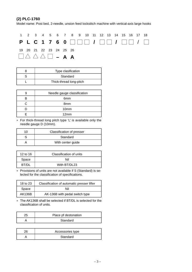
(2) PLC-1760Model name: Post bed, 2-needle, unsion feed lockstitch machine with vertical-axis large hooks
1 2 3 4 5 6 7 8 9 10 11 12 13 14 15 16 17 18
P L C 1 7 6 0 / / /19 20 21 22 23 24 25 26
– A A
8 Type clasification
S Standard
L Thick-thread long-pitch
9 Needle gauge classification
B 6mm
C 8mm
D 10mm
E 12mm
25 Place pf destonation
A Standard
26 Accessories type
A Standard
∗ For thick-thread long pitch type ‘L’ is available only theneedle gauge D (10mm).
10 Classification of presser
S Standard
A With center guide
12 to 16 Classification of units
Space Nil
BT/DL With BT/DL23
18 to 23 Classification of automatic presser lifter
Space Nil
AK136B AK-136B with pedal switch type
∗ Provisions of units are not available if S (Standard) is se-lected for the classification of specifications.
∗ The AK136B shall be selected if BT/DL is selected for theclassification of units.

– 4 –
(3) PLC-1710-7Model name: Post bed, 1-needle, unison feed, lockstitch machine with a vertical-axis large hook, with automaticthread trimmer
1 2 3 4 5 6 7 8 9 10 11 12 13 14 15 16 17 18 19 20
P L C 1 7 1 0 S 7 0 B A K 1 3 6 B – A A
8 Type clasification
S Standard
12 to 17 Classification of automatic presser lifter
AK136B AK-136B with pedal switch type
19 Place pf destonation
A Standard
20 Accessories type
A Standard

– 5 –
(4) PLC-1760-7Model name: Post bed, 2-needle, unison feed, lockstitch machine with a vertical-axis large hooks, with automaticthread trimmer
1 2 3 4 5 6 7 8 9 10 11 12 13 14 15 16 17 18
P L C 1 7 6 0 S 7 0 B A K 1 3 619 20 21 22
B – A A
8 Type clasification
S Standard
9 Needle gauge classification
B 6mm
C 8mm
D 10mm
E 12mm
21 Place pf destonation
A Standard
22 Accessories type
A Standard
10 Classification of presser
S Standard
A With center guide
14 to 19 Classification of automatic presser lifter
AK136B AK-136B with pedal switch type

– 6 –
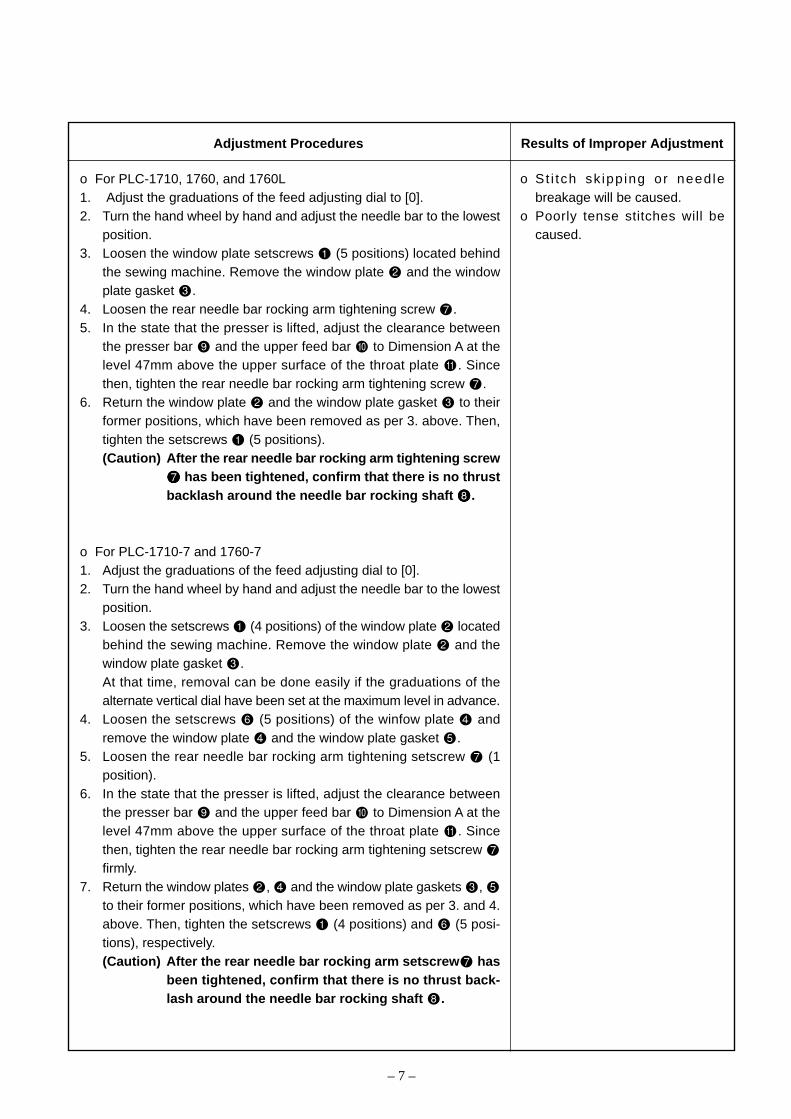
o PLC-1710, 1760, 1760L o PLC-1710-7, 1760-7
3. Standard adjustment(1) Needle entry position
Model Dimension A
PLC-1710
PLC-1760
PLC-1710-7
PLC-1760-7
PLC-1760L 9.9±0.15mm
9.5±0.15mm
10.5±0.15mm
A
47m
m
Standard Adjustment
– 7 –
o For PLC-1710, 1760, and 1760L1. Adjust the graduations of the feed adjusting dial to [0].2. Turn the hand wheel by hand and adjust the needle bar to the lowest
position.3. Loosen the window plate setscrews (5 positions) located behind
the sewing machine. Remove the window plate and the windowplate gasket .
4. Loosen the rear needle bar rocking arm tightening screw .5. In the state that the presser is lifted, adjust the clearance between
the presser bar and the upper feed bar to Dimension A at thelevel 47mm above the upper surface of the throat plate . Sincethen, tighten the rear needle bar rocking arm tightening screw .
6. Return the window plate and the window plate gasket to theirformer positions, which have been removed as per 3. above. Then,tighten the setscrews (5 positions).(Caution) After the rear needle bar rocking arm tightening screw
has been tightened, confirm that there is no thrustbacklash around the needle bar rocking shaft .
o For PLC-1710-7 and 1760-71. Adjust the graduations of the feed adjusting dial to [0].2. Turn the hand wheel by hand and adjust the needle bar to the lowest
position.3. Loosen the setscrews (4 positions) of the window plate located
behind the sewing machine. Remove the window plate and thewindow plate gasket .At that time, removal can be done easily if the graduations of thealternate vertical dial have been set at the maximum level in advance.
4. Loosen the setscrews (5 positions) of the winfow plate andremove the window plate and the window plate gasket .
5. Loosen the rear needle bar rocking arm tightening setscrew (1position).
6. In the state that the presser is lifted, adjust the clearance betweenthe presser bar and the upper feed bar to Dimension A at thelevel 47mm above the upper surface of the throat plate . Sincethen, tighten the rear needle bar rocking arm tightening setscrew firmly.
7. Return the window plates , and the window plate gaskets , to their former positions, which have been removed as per 3. and 4.above. Then, tighten the setscrews (4 positions) and (5 posi-tions), respectively.(Caution) After the rear needle bar rocking arm setscrew has
been tightened, confirm that there is no thrust back-lash around the needle bar rocking shaft .
o St i tch sk ipp ing or needlebreakage will be caused.
o Poorly tense stitches will becaused.
Adjustment Procedures Results of Improper Adjustment

– 8 –
(2) Adjustment of the feed dog position
PLC-1710PLC-1710-7
PLC-1760PLC-1760-7PLC-1760L
Standard Adjustment
PLC-1710PLC-1710-7
PLC-1760PLC-1760-7PLC-1760L
1-needle 2-needle

– 9 –
1. Adjust the graduations of the feed adjusting dial to [0].2. Let the sewing machine fall down.3. Loosen the vertical feed cam setscrews (2 positions).4. Loosen the feed bracket arm tightening setscrews (2 positions).5. Raise the sewing machine.6. Loosen the throat plate setscrews (2 positions) and remove the
throat plate .7. Loosen the throat plate holder setscrews (1-needle: 6 positions,
2-needle: 10 positions) and remove the throat plate holder .8. Loosen the hook shaft base cover setscrews (1-needle: 4 posi-
tions, 2-needle: 8 positions) and remove the hook shaft base cover.
9. Loosen the feeding lever base setscrews (4 positions).Turn the hand wheel slowly so that the needle bar is adjusted to thelowest position.
11. Move the feeding lever base to the right and left so that the needlecenter can coincide with the needle hole center of the feed dog. Atthat time, the feed bed arm should also be moved.
12. Fix the feeding lever base with the feeding lever base setscrews (4 positions).
13. Let the sewing machine fall down.14. Confirm that there is coincidence between the needle center and the
needle hole center of the feed dog and tighten the feed bracket armtightening setscrews (2 positions).
15. Thighten the vertical feed cam setscrews (2 positions). For moredetails, refer to (11)-3, Vertical feed cam phase.
16. Raise the sewing machine.17. Fix the throat plate holder with the throat plate holder setscrews
(1-needle: 6 positions, 2-needle: 10 positions).18. Fix the throat plate with the throat plate setscrews (2 positions).19. Fix the hook shaft bed cover with the hook shaft bed cover set-
screws (1-needle: 4 positions, 2-needle: 8 positions).
o If the throat plate should comein contact with the feed dog,hitting sound will be generated,and the throat plate and thefeed teeth may be broken.
o Uneven stitching will be caused.
Adjustment Procedures Results of Improper Adjustment
– 10 –
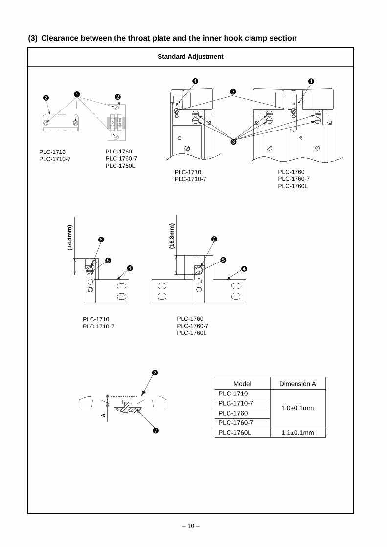
(3) Clearance between the throat plate and the inner hook clamp section
Model Dimension A
PLC-1710
PLC-1710-7
PLC-1760
PLC-1760-7
PLC-1760L 1.1±0.1mm
1.0±0.1mm
PLC-1710PLC-1710-7
PLC-1760PLC-1760-7PLC-1760L
PLC-1710PLC-1710-7
PLC-1760PLC-1760-7PLC-1760L
(14.
4mm
)
(16.
8mm
)
PLC-1710PLC-1710-7
PLC-1760PLC-1760-7PLC-1760L
A
Standard Adjustment
– 11 –
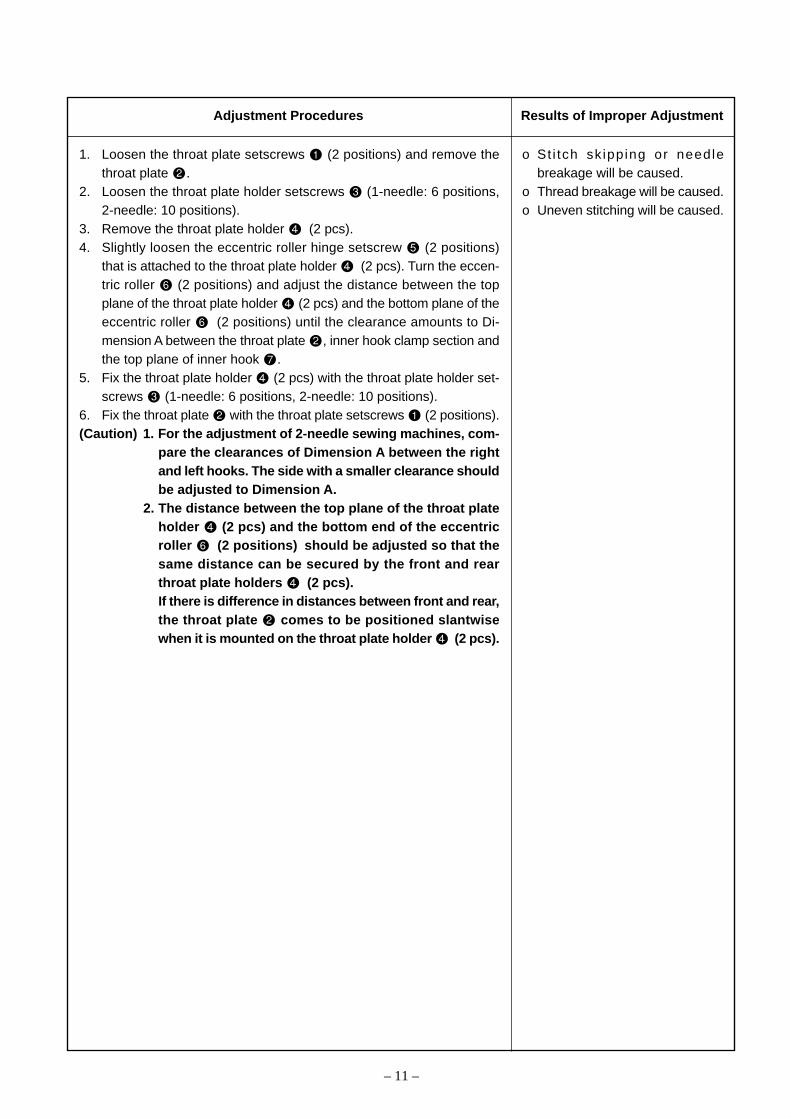
1. Loosen the throat plate setscrews (2 positions) and remove thethroat plate .
2. Loosen the throat plate holder setscrews (1-needle: 6 positions,2-needle: 10 positions).
3. Remove the throat plate holder (2 pcs).4. Slightly loosen the eccentric roller hinge setscrew (2 positions)
that is attached to the throat plate holder (2 pcs). Turn the eccen-tric roller (2 positions) and adjust the distance between the topplane of the throat plate holder (2 pcs) and the bottom plane of theeccentric roller (2 positions) until the clearance amounts to Di-mension A between the throat plate , inner hook clamp section andthe top plane of inner hook .
5. Fix the throat plate holder (2 pcs) with the throat plate holder set-screws (1-needle: 6 positions, 2-needle: 10 positions).
6. Fix the throat plate with the throat plate setscrews (2 positions).(Caution) 1. For the adjustment of 2-needle sewing machines, com-
pare the clearances of Dimension A between the rightand left hooks. The side with a smaller clearance shouldbe adjusted to Dimension A.
2. The distance between the top plane of the throat plateholder (2 pcs) and the bottom end of the eccentricroller (2 positions) should be adjusted so that thesame distance can be secured by the front and rearthroat plate holders (2 pcs).If there is difference in distances between front and rear,the throat plate comes to be positioned slantwisewhen it is mounted on the throat plate holder (2 pcs).
o St i tch sk ipping or needlebreakage will be caused.
o Thread breakage will be caused.o Uneven stitching will be caused.
Adjustment Procedures Results of Improper Adjustment

– 12 –
(4) Height of the feed dog
Model Dimension A
PLC-1710
PLC-1710-7
PLC-1760
PLC-1760-7
PLC-1760L 0.9 to 1.1mm
0.6 to 0.7mm
0.7 to 0.9mm
A
PLC-1710-7PLC-1760-7
PLC-1710PLC-1760PLC-1760L
Standard Adjustment

– 13 –
o For PLC-1710-7 and 1760-71. Adjust the graduations of the feed adjusting dial to [0].2. Turn the hand wheel and stop it where the amount of protrusion of
the feed dog , appearing from the throat plate top face , be-comes maximum.
3. Loosen the setscrew (1 position) of the feed bar fork and move thefeed bar fork up and down so that the height of the feed dog can be adjusted to Dimension A.
4. Firmly tighten the setscrew of the feed bar fork.
o For PLC-1710, 1760, and 1760L1. Adjust the graduations of the feed adjusting dial to [0].2. Turn the hand wheel and stop it where the amount of protrusion of
the feed dog , appearing from the throat plate top face , be-comes maximum.
3. Loosen the setscrew of the vertical feed link shaft and turn thevertical feed link shaft until the height of the feed dog adjustedto Dimension A.
4. Tighten the vertical feed link shaft setscrew firmly.
If the height of the feed dog isexcessive:o The pitches of stitches become
greater than the graduations ofthe feed adjusting dial.
o Isolated idling loops will result.o A return of the sewing object is
caused.If the height of the feed dog isinsufficient:o The pitches of stitches become
smaller than the graduations ofthe feed adjusting dial.
o The feeding force is weakened.
Adjustment Procedures Results of Improper Adjustment
– 14 –
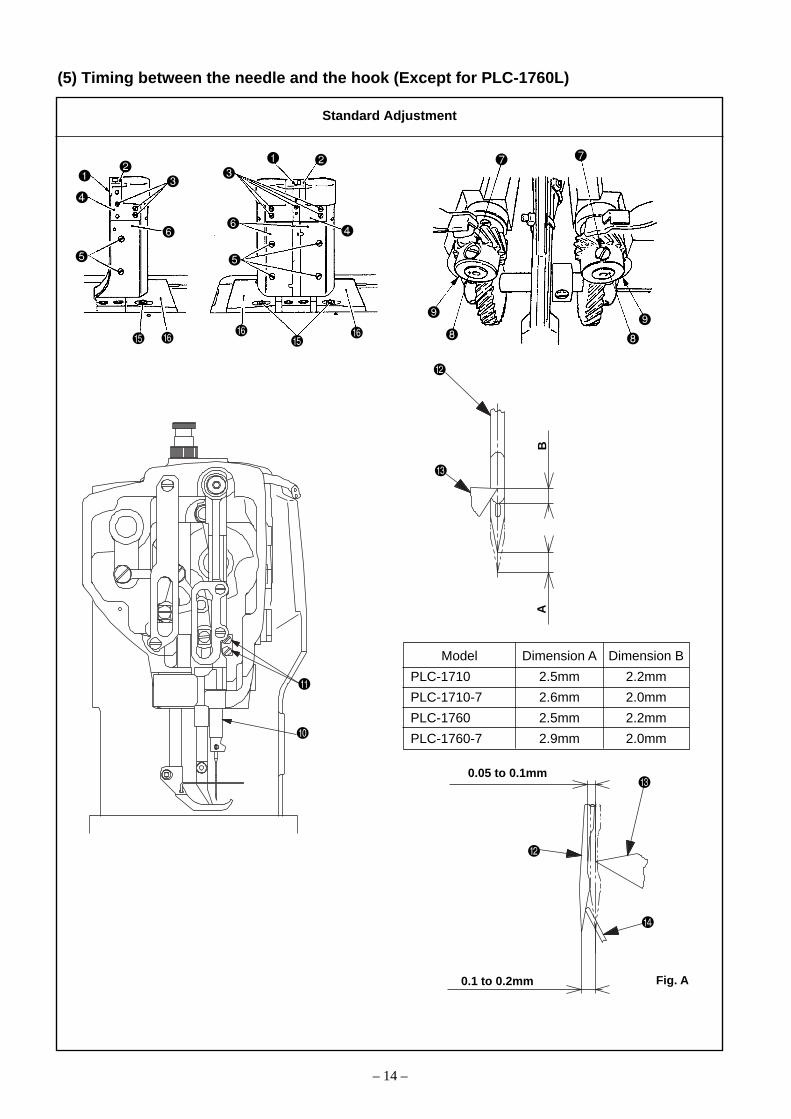
(5) Timing between the needle and the hook (Except for PLC-1760L)
Model Dimension A Dimension B
PLC-1710 2.5mm 2.2mm
PLC-1710-7 2.6mm 2.0mm
PLC-1760 2.5mm 2.2mm
PLC-1760-7 2.9mm 2.0mm
BA
0.05 to 0.1mm
0.1 to 0.2mm Fig. A
Standard Adjustment

– 15 –
(Caution) 1. In the case of the 2-needle sewing machine, the same ad-justing values should be secured for both right and left.
2. In the case of the thread trimming machine, workshould be started after the eocking arm and the threadtrimmer driving joint plate have been removed. Theseshould be remounted after the completion of this work.Refer to 3.-(18) –1) to 9), Thread trimming device.
1. Adjust the graduations of the feed adjusting dial to [0].2. Loosen the throat plate setscrews (2 positions) and remove the
throat plate .3. Loosen the throat plate holder setscrews (1-needle: 6 positions,
2-needle: 10 positions) and remove the throat plate holder .4. Loosen the hook shaft base cover setscrews (1-needle: 4 positions,
2-needle: 8 positions) and remove the hook shaft base cover .5. Let the sewing machine fall down and loosen the hook shaft gear
setscrews (1-needle: 3 positions, 2-needle: 6 positions) so thatthe hook shaft can be made free.For PLC-1710 and PLC-1760, remove the hook shaft gear .
6. Raise the sewing machine.7. Turn the hand wheel by hand and raise the needle bar from the
lowest position to Dimension A.8. Loosen the needle bar connection setscrews (2 positions).
If they are loosened too much at that time, the needle bar willcome down. Therefore, they should be loosened to a degree wherethe needle bar can be moved vertically by hand.
9. Move the needle bar vertically by hand so that the hook blade tip comes to the height of Dimension B, measured from the needle
hole upper end of the needle .10. Thighten the setscrews (2 positions) of the needle bar connection.11. Bend the hook’s needle guard in the direction of the hook center
so that the effective amount of the needle guard is reduced to 0.12. Loosen the hook shaft base setscrews (1-needle: 2 positions, 2-
needle: 4 positions).13. Turn the hand wheel by hand and raise the needle bar from the
lowest position to Dimension A.14. In the state that there is no contact between the needle and the
hook’s needle guard , move and adjust the hook shaft base tothe right and left so that a clearance of 0 to 0.1mm can be securedbetween the needle and the hook blade tip .
15. After adjustments, tighten the setscrews (1-needle: 2 positions, 2-needle: 4 positions) of the hook shaft base.
16. Let the sewing machine fall down again and turn the hook by hand inthe state of 13. above. Adjust the hook blade tip to the center ofthe needle and fix the hook shaft gear with the use of the hookshaft gear setscrews (1-needle: 3 positions, 2-needle: 6 positions).
17. Raise the sewing machine.18. Confirm that a coincidence is secured between the center of the needle
and the hook blade tip when the needle bar is raised fromthe lowest position to Dimension A. Otherwise, the work of 16. shouldbe carried out once more again.
19. Bend the hook’s needle guard so that the effective amount of thehook’s needle guard is adjusted to 0.1 to 0.2mm at the tip of theneedle . Refer to Fig. A.
20. Install the throat plate holder with the throat plate holder setscrews (1-needle: 6 positions, 2-needle: 10 positions).
21. Install the throat plate with the throat plate setscrews (2 posi-tions).
22. Install the hook shaft base cover with the hook shaft base coversetscrews (1-needle: 4 positions, 2-needle: 8 positions).
o Stitch skipping or thread break-age will be caused.
o Poorly tense stitches will becaused.
Adjustment Procedures Results of Improper Adjustment

– 16 –
(6) Timing between the needle and the hook (PLC-1760L)
2.0m
m2.
5mm
0.05 to 0.1mm
0.1 to 0.2mm
Fig. A
Standard Adjustment

– 17 –
(Caution) The same adjusting values should be secured for both right andleft.
1. Adjust the graduations of the feed adjusting dial to [0].2. Loosen the throat plate setscrews (2 positions) and remove the throat
plate .3. Loosen the throat plate holder setscrews (10 positions) and remove the
throat plate holder .4. Loosen the hook shaft base cover setscrews (8 positions) and remove
the hook shaft base cover .5. Lay down the sewing machine body and loosen the hook shaft gear set-
screws (6 positions). Remove the hook shaft gear and raise the sew-ing machine body.
6. Loosen the needle bar connection setscrews (2 positions).If they are loosened too much at that time, the needle bar will come down.Therefore, they should be loosened to a degree where the needle bar canbe moved vertically by hand.
7. Turn the hand wheel by hand so that the needle bar is positioned 2.5mmabove its lowest position.
8. Turn the hook by hand so that the center of the needle coincides with thehook blade tip .
9. Move the needle bar vertically by hand so that a distance of 2.0mm canbe secured between the needle hole upper end of the needle and thehook blade tip .
10. Thighten the needle bar connection setscrew (2 positions).11. Bend the hook’s needle guard in the direction of the hook center so that
the effective amount of the needle guard is reduced to 0.12. Loosen the right and left hook shaft base setscrews (4 positions).13. Turn the hand wheel by hand so that the needle bar is positioned 2.5mm
above its lowest position.14. In the state that there is no contact between the needle and the hook’s
needle guard , move and adjust the hook shaft base to the right and leftso that a clearance of 0.05 to 0.1mm can be secured between the needle and the hook blade tip .
15. After adjustments, tighten the hook shaft base setscrews (4 positions).16. Let the sewing machine fall down and loosen the lower shaft gear setscrews
(4 positions). Move the lower shaft gear so that the center of the hookshaft can coincide with that of the gear section of the lower shaft gear .
17. Temporarily tighten the lower shaft gear with the lower shaft gear set-screw .At that time, tentatively fasten the first screw of the lower shaft gear setscrew
adjusted to the flat section of the lower shaft.18. Assume the condition of 13. again and let the center of the needle coin-
cide with the hook blade tip . Mount the hook shaft gear and firmlytighten it by means of the hook shaft gear setscrews (6 positions).At that time, tighten the first screw of the hook shaft gear setscrew ad-justed to the flat section of the hook shaft .
19. Loosen the lower shaft gear setscrew that has been fastened tentativelyas per 17. above so that the lower shaft gear can be moved to the rightand left.At that time, the first screw of the lower shaft gear setscrews should havebeen loosened to an extent that it is not disengaged from the flat section ofthe lower shaft.
20. Move and adjust the lower shaft gear in the direction of the arrow so thatthe center of the needle can coincide with the hook blade tip when theneedle bar is raised by 2.5mm from the lowest position of the needle bar.Tighten the lower shaft gear setscrews (4 positions).
21. Raise the sewing machine.22. Bend the hook’s needle guard so that the effective amount of the hook’s
needle guard is adjusted to 0.1 to 0.2mm at the tip of the needle .Refer to Fig. A.
23. Install the throat plate holder with the throat plate holder setscrews (10positions).
24. Install the throat plate with the setscrews (2 positions).25. Install the hook shaft base cover with the hook shaft base cover set-
screws (8 positions).
o St i tch sk ipp ing or threadbreakage will be caused.
o Poorly tense stitches will becaused.
Adjustment Procedures Results of Improper Adjustment

– 18 –
(7) Adjusting the inner hook guide
Model Dimension A
PLC-1710
PLC-1710-7 0.1 to 0.3mm
PLC-1760-7
PLC-1760 0.2 to 0.4mm
PLC-1760L 0.3 to 0.5mm
PLC-1710PLC-1710-7
PLC-1760PLC-1760-7PLC-1760L
A
A
Contact
Standard Adjustment
1-needle 2-needle
– 19 –
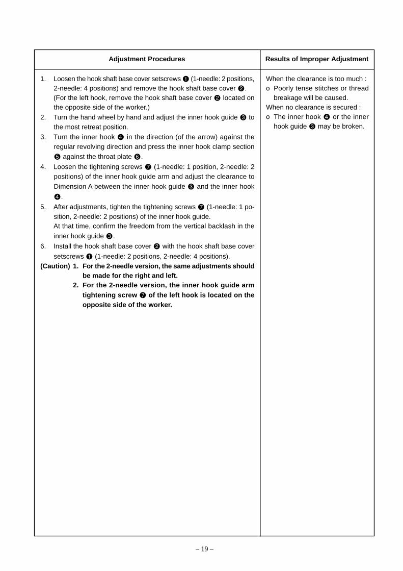
1. Loosen the hook shaft base cover setscrews (1-needle: 2 positions,2-needle: 4 positions) and remove the hook shaft base cover .(For the left hook, remove the hook shaft base cover located onthe opposite side of the worker.)
2. Turn the hand wheel by hand and adjust the inner hook guide tothe most retreat position.
3. Turn the inner hook in the direction (of the arrow) against theregular revolving direction and press the inner hook clamp section
against the throat plate .
4. Loosen the tightening screws (1-needle: 1 position, 2-needle: 2positions) of the inner hook guide arm and adjust the clearance to
Dimension A between the inner hook guide and the inner hook
.
5. After adjustments, tighten the tightening screws (1-needle: 1 po-sition, 2-needle: 2 positions) of the inner hook guide.At that time, confirm the freedom from the vertical backlash in the
inner hook guide .
6. Install the hook shaft base cover with the hook shaft base cover
setscrews (1-needle: 2 positions, 2-needle: 4 positions).(Caution) 1. For the 2-needle version, the same adjustments should
be made for the right and left.2. For the 2-needle version, the inner hook guide arm
tightening screw of the left hook is located on theopposite side of the worker.
When the clearance is too much :o Poorly tense stitches or thread
breakage will be caused.When no clearance is secured :o The inner hook or the inner
hook guide may be broken.
Adjustment Procedures Results of Improper Adjustment

– 20 –
1) Presser lifter lever
2) Using a knee lifter (PLC-1710, 1760, 1760L)
3) Auto presser lifter (PLC-1710-7, 1760-7)
(8) Lifting amount of presser
9±0.
3mm
Using a knee lifter lever A
16±0
.5m
m
B
A 0.5
to 1
.5m
m
Standard Adjustment
Using a knee lifter lever B
16±0
.5m
m

– 21 –
1) Presser lifter lever1. Loosen the side cover setscrew (1 position) located on the arm’s
opposite side of the worker and remove the side cover .(PLC-1710, 1760, 1760L only)
2. Loosen the presser bar connecting bracket tightening screw (1position) in the state that the presser lifting lever is lifted.
3. Adjust the amount of presser rise to 9 ± 0.3mm. In this case, adjust-ments become easy if a sewing material of 9mm in thickness is in-serted in between the top face of the throat plate and the bottomface of the presser foot
4. After adjustments, tighten the hook shaft base screw (1 position).Prior to tightening, confirm that there is no contact between the presserfoot and the feed foot .
5. Remove the object inserted in the clearance between the top face ofthe throat plate and the bottom face of the presser foot .
6. Install the side cover and tighten the side cover setscrew (1position). (PLC-1710, 1760, 1760L only)
2) Using a knee lifter (PLC-1710, 1760, 1760L)1. Remove the knee patch plate and let the sewing machine fall down.2. Loosen the stopper nut (1 position) and adjust the lifting amount
by changing the screw-in value of the stopper screw . Adjust thedistance to 16±0.5mm between the top face of the throat plate and the bottom face of the presser foot .
3. Make sure not to move the stopper screw while the stopper nut is tightened.o Stopper screw tightened → Decrease in the amount of riseo Stopper screw loosened → Increase in the amount of rise
3) Auto presser lifter (PLC-1710-7, 1760-7)1. Loosen the cylinder nut and adjust the screw-in value of the cylin-
der connecting screw by turning the shaft section of the cylinder so that the distance can be adjusted to 16 ± 0.5mm between the
top face of the throat plate and the bottom face of the presser foot.
Turned in the direction A → Increase in the lifting amount of thepresser foot .
Turned in the direction B → Decrease in the lifting amount of thepresser foot .
2. After adjustments, tighten the cylinder nut .(Caution) After adjustments, confirm that a clearance of 0.5 - 1.
5mm is secured between the auto presser lifter lever A and the thread tension releasing support plate whenthe presser foot is lowered.
When the amount of presser rise istoo much:o The presser foot is kept clear
of the top face of the throat plate even when the presser lifter
lever is returned to its origi-nal position.
When the amount of presser rise istoo less:o Since the rise of the presser is
insufficient, the workability canbecome worse.
When the amount of presser rise istoo much:o When the presser is lifted, the tip
of the needle bar may interferewith the feed foot and the feedfoot may be broken.
When the amount of presser rise istoo less:o Since the rise of the presser is
insufficient, the workability canbecome worse.
When the amount of presser rise istoo much:o When the presser is lifted, the tip
of the needle bar may interferewith the feed foot and the feedfoot may be broken.
When the amount of presser rise istoo less:o Since the rise of the presser is
insufficient, the workability canbecome worse.
Adjustment Procedures Results of Improper Adjustment
– 22 –
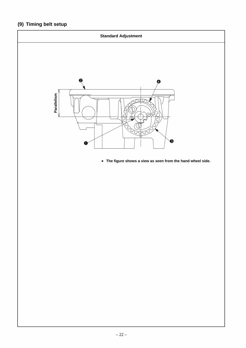
(9) Timing belt setup
∗∗∗∗∗ The figure shows a view as seen from the hand wheel side.
Par
alle
lism
Standard Adjustment
– 23 –
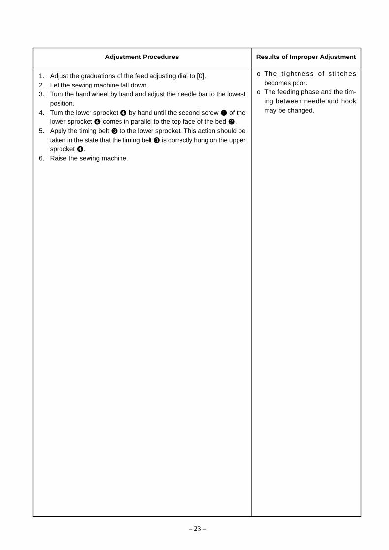
1. Adjust the graduations of the feed adjusting dial to [0].2. Let the sewing machine fall down.3. Turn the hand wheel by hand and adjust the needle bar to the lowest
position.4. Turn the lower sprocket by hand until the second screw of the
lower sprocket comes in parallel to the top face of the bed .5. Apply the timing belt to the lower sprocket. This action should be
taken in the state that the timing belt is correctly hung on the uppersprocket .
6. Raise the sewing machine.
o The t ightness of s t i tchesbecomes poor.
o The feeding phase and the tim-ing between needle and hookmay be changed.
Adjustment Procedures Results of Improper Adjustment
– 24 –
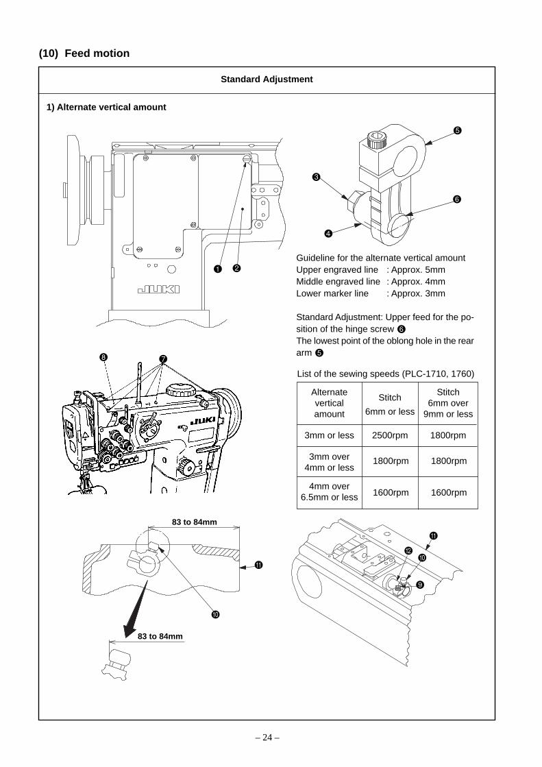
(10) Feed motion
1) Alternate vertical amount
Guideline for the alternate vertical amountUpper engraved line : Approx. 5mmMiddle engraved line : Approx. 4mmLower marker line : Approx. 3mm
Standard Adjustment: Upper feed for the po-sition of the hinge screw The lowest point of the oblong hole in the reararm
List of the sewing speeds (PLC-1710, 1760)
Alternate Stitchvertical 6mm overamount 9mm or less
3mm or less 2500rpm 1800rpm
3mm over4mm or less
4mm over6.5mm or less
1800rpm 1800rpm
1600rpm 1600rpm
Stitch
6mm or less
83 to 84mm
83 to 84mm
Standard Adjustment

– 25 –
o For PLC-1710 and PLC-17601. Loosen the window plate screw (1 position) and remove the win-
dow plate .2. Loosen the upper feed rod hinge screw nut .3. Vertically move and adjust the position of the cam rod boss .4. Tighten the upper feed rod hinge screw nut .5. Install the window plate with the window plate setscrews (2
positions).o Upper section of the oblong hole → Alternate vertical amount: Largeo Lower section of the oblong hole → Alternate vertical amount: Small(Caution) The maximum revolving speed has been set according to
the sewing conditions. Set the maximum revolving speedaccording to each sewing condition so that the presetvalue cannot be exceeded.
o For PLC-1710-7, 1760-7, 1760L1. Set the graduations of the alternate vertical dial at the lowest level.2. Loosen the top cover setscrews (6 positions) and remove the top
cover .3. Loosen the Alternate vertical adjusting arm setscrew (1 position).4. The position of the alternate vertical adjusting arm pin is main-
tained at 83 to 84mm when measured from the arm end face . Inthe sidewise direction, it is positioned to coincide with the end face ofthe alternate vertical converter shaft .
5. Tighten the Alternate vertical adjusting arm setscrew (1 position).6. Set the graduations of the alternate vertical dial at the lowest level.
Use the top cover setscrews (6 positions) to mount the top cover.
7. Turn the alternate vertical dial and confirm that the dial digits cor-rectly correspond to the alternate vertical amounts.
For certain types of sewing
materials, the working height maybe increased.o Sewing of sponge materialso Sewing of stepped sectionso When the working value is in-
creased, difference may becaused between the stitchingpitches and dial graduations.
o When the working value is in-creased, the feeding force maybe reduced. Accordingly, themotor speed should be some-what lowered in such a case.
For certain types of sewing materi-als, the working height may be in-creased.o Sewing of sponge materialso Sewing of stepped sections
Adjustment Procedures Results of Improper Adjustment
– 26 –
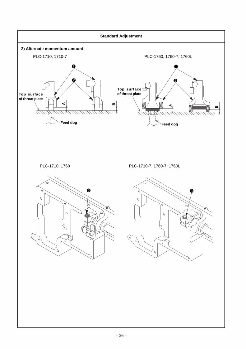
2) Alternate momentum amount
PLC-1710, 1710-7 PLC-1760, 1760-7, 1760L
Top surfaceof throat plate
Feed dog
A AB
B
PLC-1710, 1760 PLC-1710-7, 1760-7, 1760L
Standard Adjustment
Top surfaceof throat plate
Feed dog

– 27 –
o For PLC-1710 and PLC-17601. Adjust the graduations of the feed adjusting dial to [0].2. Turn the hand wheel by hand and confirm whether the vertical amount
of motion is kept almost equalized between the feed foot and thepresser foot .
3. If the vertical amount of motion seems to be different, loosen theupper feed rear arm setscrew until equalized balancing is secured.Make adjustments until the condition of A = B is secured by visualcheck.
When the vertical amount of motion is too much in the feed foot :1. In the state that the feed foot is somewhat lifted, loosen the upper
feed rear arm setscrew and press the feed foot against thefeed dog.
2. Tighten the upper feed rear arm setscrew again and examine thevertical amount of motion by turning the hand wheel.
When the vertical amount of motion is too much in the presser foot :1. In the state that the presser foot is somewhat lifted, loosen the
upper feed rear arm setscrew and press the presser foot againstthe throat plate.
2. Tighten the upper feed rear arm setscrew again and examine thevertical amount of motion by turning the hand wheel.
o For PLC-1710-7, 1760-7, 1760L1. Adjust the graduations of the feed adjusting dial to [0].2. Set the alternate vertical dial at the graduations [3] in the case of the
PLC-1710-7 and 1760-7, and at the graduation [2] in the case of thePLC-1760L.
3. Turn the hand wheel by hand and confirm whether the vertical amountof motion is kept almost equalized between the feed foot and thepresser foot .
4. If the vertical amount of motion seems to be different, loosen theupper feed rear arm setscrew until equalized balancing is secured.Make adjustments until the condition of A = B is secured by visualcheck.
When the vertical amount of motion is too much in the feed foot :1. In the state that the feed foot is somewhat lifted, loosen the upper
feed rear arm setscrew and press the feed foot against thefeed dog.
2. Tighten the upper feed rear arm setscrew again and examine thevertical amount of motion by turning the hand wheel.
When the vertical amount of motion is too much in the presser foot :1. In the state that the presser foot is somewhat lifted, loosen the
upper feed rear arm setscrew and press the presser foot againstthe throat plate.
2. Tighten the upper feed rear arm setscrew again and examine thevertical amount of motion by turning the hand wheel by hand.
For certain types of sewing materials,the vertical amount of motion of thefeed foot should be increased morethan that of the presser foot.o Sewing of sponge materialso Sewing of stepped sectionsWhen the vertical amount of motionis extremely different:o The pitches of stitches become
different from the graduations ofthe dial.
o Since the feeding force is re-duced, the motor speed shouldbe somewhat lowered.
For certain types of sewing materi-als, the vertical amount of motionof the feed foot should be increasedmore than that of the presser foot.o Sewing of sponge materialso Sewing of stepped sectionsWhen the vertical amount of motionis extremely different:o The pitches of stitches become
different from the graduations ofthe dial.
o Since the feeding force is re-duced, the motor speed shouldbe somewhat lowered.
Adjustment Procedures Results of Improper Adjustment

– 28 –
(11) Feed cam phase
1) Horizontal feed cam phase
* According to the model type, the shape of the top cover will change.
A
AA
A a b
2 to 3mm
Only PLC-1760L Only PLC-1760L
Besides PLC-1760L Besides PLC-1760L
Standard Adjustment
(a = b)

– 29 –
o For PLC-1710, 1710-7, 1760, 1760-71. Adjust the graduations of the feed adjusting dial to [9].2. Loosen the top cover setscrews (6 positions) on the top of the
sewing machine and remove the top cover .3. Loosen the horizontal feed eccentric cam setscrews (2 positions).4. Turn the hand wheel by hand to lift the needle from its lowest point
and stop it where the center of the needle coincides with the hookblade tip .
5. Turn and adjust the horizontal feed eccentric cam to the phasewhere the feed dog does not move even when the reverse feed lever
is moved vertically.6. Tighten the horizontal feed eccentric cam setscrews (2 positions)
filmly.7. Install the top cover with the top cover setscrews (2 positions).(Guideline) In the position where the center of the needle coincides
with the hook blade tip , the first screw of the horizontalfeed eccentric cam is faced almost above.
(Caution) 1. The torque is increased if the horizontal feed rod comes in contact with the end faces of the horizontalfeed cam cover and the horizontal feed eccentric cam
. To avoid this, the horizontal feed rod should bepositioned almost in the center of the end face of thehorizontal feed cam cover and the flange end face ofthe horizontal feed eccentric cam .
2. After the completion of horizontal feed timing adjust-ments, the top feed timing should also be adjustedagain.For more details, refer to (11)-2, Top feed cam phase.
o For PLC-1760L1. Adjust the graduations of the feed adjusting dial to [12].2. Loosen the top cover setscrews (6 positions) of the top of the
sewing machine and remove the top cover .3. Loosen the horizontal feed triangle cam setscrews (2 positions).4. Turn the hand wheel to lift the needle and stop it where the needle
attains the position that is 4mm above its lowest point.5. Turn and adjust the horizontal feed triangle cam to the phase where
the feed dog does not move even when the reverse feed lever ismoved vertically.
6. Tighten the horizontal feed triangle cam setscrews (2 positions)filmly.
7. Install the top cover with the top cover setscrews (2 positions).(Guideline) In the position where the needle bar is lifted by 4mm above
its lowest point, the first screw of the horizontal feed trianglecam is faced almost above.
(Caution) 1. The torque is increased if the horizontal feed rod comes in contact with the end face of the horizontalfeed triangle cam . To avoid this, the horizontal feedrod should be set up so that a clearance of 2 ~ 3mmis secured between the horizontal feed rod and theflange end face of the horizontal feed triangle cam .
2. After the completion of horizontal feed timing adjust-ments, the top feed timing should also be adjustedagain.For more details, refer to (11)-2, Top feed cam phase.
o High and low speed pitch errorsbecome worse.
o Thread tension changes.o Forward and reverse stitch tight-
ness changes.
o High and low speed pitch errorsbecome worse.
o Thread tension changes.o Forward and reverse stitch tight-
ness changes.
Adjustment Procedures Results of Improper Adjustment

– 30 –
2) Top feed cam phase
To align
AB
To align
A=B
PLC-1710,1760 PLC-1710, 1760
PLC-1710, 1760, 1760L
PLC-1710-7, 1760-7, 1760L PLC-1710-7, 1760-7, 1760L
PLC-1710-7, 1760-7, 1760L PLC-1710-7, 1760-7
Standard Adjustment
– 31 –
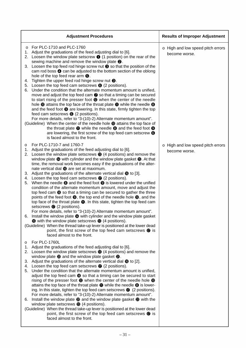
o For PLC-1710 and PLC-17601. Adjust the graduations of the feed adjusting dial to [6].2. Loosen the window plate setscrew (1 position) on the rear of the
sewing machine and remove the window plate .3. Loosen the top feed rod hinge screw nut so that the position of the
cam rod boss can be adjusted to the bottom section of the oblonghole of the top feed rear arm .
4. Tighten the upper feed rod hinge screw nut .5. Loosen the top feed cam setscrews (2 positions).6. Under the condition that the alternate momentum amount is unified,
move and adjust the top feed cam so that a timing can be securedto start rising of the presser foot when the center of the needlehole attains the top face of the throat plate while the needle and the feed foot are lowering. In this state, firmly tighten the topfeed cam setscrews (2 positions).For more details, refer to “3-(10)-2) Alternate momentum amount”.
(Guideline) When the center of the needle hole attains the top face ofthe throat plate while the needle and the feed foot are lowering, the first screw of the top feed cam setscrew is faced almost to the front.
o For PLC-1710-7 and 1760-71. Adjust the graduations of the feed adjusting dial to [6].2. Loosen the window plate setscrews (4 positions) and remove the
window plate with cylinder and the window plate gasket . At thattime, the removal work becomes easy if the graduations of the alter-nate vertical dial are set at maximum.
3. Adjust the graduations of the alternate vertical dial to [3].4. Loosen the top feed cam setscrews (2 positions).5. When the needle and the feed foot is lowered under the unified
condition of the alternate momentum amount, move and adjust thetop feed cam so that a timing can be secured to gather the threepoints of the feed foot , the top end of the needle hole , and thetop face of the throat plate . In this state, tighten the top feed camsetscrews (2 positions).For more details, refer to “3-(10)-2) Alternate momentum amount”.
6. Install the window plate with cylinder and the window plate gasket with the window plate setscrews (4 positions).
(Guideline) When the thread take-up lever is positioned at the lower deadpoint, the first screw of the top feed cam setscrews isfaced almost to the front.
o For PLC-1760L1. Adjust the graduations of the feed adjusting dial to [6].2. Loosen the window plate setscrews (4 positions) and remove the
window plate and the window plate gasket .3. Adjust the graduations of the alternate vertical dial to [2].4. Loosen the top feed cam setscrews (2 positions).5. Under the condition that the alternate momentum amount is unified,
adjust the top feed cam so that a timing can be secured to startrising of the presser foot when the center of the needle hole attains the top face of the throat plate while the needle is lower-ing. In this state, tighten the top feed cam setscrews (2 positions).For more details, refer to “3-(10)-2) Alternate momentum amount”.
6. Install the window plate and the window plate gasket with thewindow plate setscrews (4 positions).
(Guideline) When the thread take-up lever is positioned at the lower deadpoint, the first screw of the top feed cam setscrews isfaced almost to the front.
o High and low speed pitch errorsbecome worse.
o High and low speed pitch errorsbecome worse.
Adjustment Procedures Results of Improper Adjustment
– 32 –
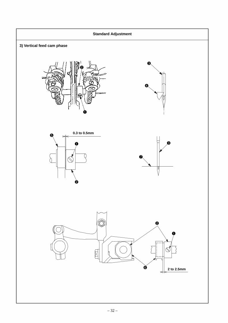
3) Vertical feed cam phase
0.3 to 0.5mm
2 to 2.5mm
Standard Adjustment

– 33 –
o For PLC-1710, 1760, and 1760L1. Adjust the graduations of the feed adjusting dial to [0].2. Let the sewing machine fall down.3. Loosen the vertical feed cam setscrews (2 positions).4. Turn the hand wheel by hand to the position where the needle
coincides with the hook blade tip .5. Turn the vertical feed cam by hand to the position where the amount
of protrusion of the feed dog becomes maximum from the top face of the throat plate.
6. Tighten the vertical feed cam setscrews (2 positions) and fix thevertical feed cam .
7. Raise the sewing machine.(Caution) 1. Secure a clearance of 0.3 to 0.5mm between the end
face of the vertical feed link and the flange end faceof the vertical feed cam .
2. Prior to making adjustments for this item, confirmwhether the feed dog height has been correctly ad-justed.For more details, refer to 3.-(4) Height of the feed dog.
o For PLC-1710-7 and 1760-71. Adjust the graduations of the feed adjusting dial to [0].2. Let the sewing machine fall down.3. Loosen the vertical feed cam setscrews (2 positions).4. Turn the hand wheel and adjust it to the position where the top end of
the needle hole coincides with the top face of the throat plate while the needle is lowering.
5. Turn the vertical feed cam by hand to the position where the topface of the throat plate of the throat plate coincides with the high-est part of the feed dog.
6. Tighten the vertical feed cam setscrews (2 positions) and fix thevertical feed cam .
7. Raise the sewing machine.(Caution) 1. Secure a clearance of 2 to 2.5mm between the end face
of the vertical feed slide block and the flange endface of the vertical feed cam .
2. Prior to making adjustments for this item, confirmwhether the feed dog height has been correctly ad-justed.For more details, refer to 3.-(4) Height of the feed dog.
o If the throat plate should comein contact with the feed dog,hitting sound will be generated,and the throat plate and the feeddog may be broken.
o Uneven stitching will be caused.
Adjustment Procedures Results of Improper Adjustment

– 34 –
(12) Needle motion
(13) Normal and reverse stitch length
20±0.5mm
A
B
Standard Adjustment
Standard Adjustment

– 35 –
o This can be the cause of needlebreakage or stitch skipping.
1. Let the sewing machine fall down.2. Loosen the horizontal feed rear arm hinge screw nut .3. Move the horizontal feed connecting rod until the distance from
the shaft center of the horizontal feed shaft to the hinge screwcenter becomes 20 ± 0.5mm. After the horizontal feeding, tightenthe rear arm hinge screw nut .
4. Turn the hand wheel and check the needle motion.5. Raise the sewing machine.(Guideline) 1. The engraved marker line of the horizontal feed rear
arm coincides with the center of the hinge screw.2. If the distance is increased more than the standard adjust-
ing value (20 ± 0.5mm), the amount of bottom feed is re-duced.
o The stitch length becomesirregular between forward andreverse feed.
1. Loosen the top cover setscrews (6 positions) and remove the topcover .
2. Adjust the graduations of the feed adjusting dial to [6].(For the PLC-1760L, adjust it to [12].)
3. Loosen the feed adjusting eccentric pin setscrews (2 positions).4. Turn the feed adjusting eccentric pin and adjust the it.
o Direction A → Reverse feed pitch increasedo Direction B → Forward feed pitch increased
5. Tighten the feed adjusting eccentric pin setscrews (2 positions).6. Install the top cover with the top cover screws (6 positions).(Guideline) When the notch direction of the feed adjust eccentric pin
is positioned sidewise, the amount of feed becomes al-most the same between forward and reverse.
Adjustment Procedures Results of Improper Adjustment
Adjustment Procedures Results of Improper Adjustment

– 36 –
(14) Balance
The above illustration shows a view of the arm interior as seen from the worker side.
A
Z-ZZ
A
Z
0.8 to 1.0mm
PLC-1710, 1760 PLC-1710, 1760
PLC-1710, 1760
PLC-1710-, 1760-7, 1760L PLC-1710-7, 1760-7, 1760L
Standard Adjustment

– 37 –
o For PLC-1710, 17601. Loosen the top cover setscrews (6 positions) and remove the top
cover .2. Loosen the balancer setscrews (2 positions).3. Adjust Section A of the balancer to the position where it coincides
with the second screw of the horizontal feed cam setscrew . Fixthe balancer by means of the balancer setscrews (2 positions).At the time of this setup, the end face of the balancer is required tokeep a close contact with that of the top feed cam .
4. Install the top cover with the top cover setscrews (6 positions).
o For PLC-1710-7, 1760-7, 1760L1. Loosen the top cover setscrews (6 positions) and remove the top
cover .2. Loosen the oil tank setscrews (2 positions) and remove the oil
tank .3. Loosen the balancer setscrews (2 positions).4. Turn the hand wheel until the first screw of the main shaft counterbal-
ance setscrews (2 positions) is faced upwards.If a 4mm hexagon head wrench is inserted in the hole of the sew-ing machine top face at that time, it becomes easy to check the posi-tion of the main shaft counterbalance.
5. Let the first screw of the balancer setscrews (2 positions) coin-cides with that of the main shaft counterbalance setscrews (2 po-sitions), and then tighten the balancer setscrews (2 positions).At that time, a clearance of 0.8 to 1.0mm should be secured betweenthe balancer and the main shaft front metal .
6. Install the oil tank with the oil tank setscrews (2 positions).7. Install the top cover with the top cover setscrews (6 positions).
o Vibration is increased.
Adjustment Procedures Results of Improper Adjustment

– 38 –
(15) Position of reverse feed lever
1±0.
5mm
1±0.
5mm
PLC-1710-7, 1760-7 PLC-1760L
PLC-1710, 1760
PLC-1710, 1760 PLC-1710-7. 1760-7, 1760L
Standard Adjustment

– 39 –
o For PLC-1710, 17601. Adjust the graduations of the feed adjusting dial to [0].2. Loosen the window plate setscrews (5 positions) located behind
the sewing machine. Remove the window plate and the windowplate gasket .
3. Loosen the hexagon head bolt to adjust the feed adjuster sothat the top face of the reverse feed lever is positioned approxi-mately in parallel to the junction face between the arm and thepost. After adjustments, tighten this bolt .
4. Install the window plate and the window plate gasket with thewindow plate setscrews (5 positions).
(Caution) Confirm that the reverse feed lever does not interferewith the arm or the post when the graduations of the feedadjuster dial are set at [9].
o For PLC-1710-7, 1760-7, 1760L1. Adjust the graduations of the feed adjusting dial to maximum value.2. Loosen the window plate setscrews (4 positions) located behind
the sewing machine. Remove the window plate and the windowplate gasket .
3. Loosen the window plate setscrews (5 positions) located behindthe sewing machine. Remove the window plate and the windowplate gasket .
4. Loosen the hexagon head bolt to adjust the feed adjuster sothat a clearance of 1 ± 0.5mm can be secured between the reversefeed lever and the reverse feed lever stopper . After adjust-ments, tighten this bolt .
5. Install the window plate and the window plate gasket with thewindow plate setscrews (5 positions).
6. Install the window plate and the window plate gasket with thewindow plate setscrews (4 positions).
(Caution) Confirm that the reverse feed lever does not interferewith the arm or the post when the graduations of the feedadjuster dial are set at the maximum position.
When the reverse feed lever ispositioned too low:o At the time of reverse feed stitch-
ing, the reverse stitch pitchesmay be decreased as a result ofinterference between the reversefeed lever and the post.
When the reverse feed lever is po-sitioned too high:o The forward feed stitch pitches
may be decreased as a result ofinterference between the reversefeed lever and the arm.
When the clearance is too largebetween the reverse feed lever andthe stopper:o In the case of reverse feed stitch-
ing with the reverse feed lever, the reverse feed lever may
interfere with the post, thus de-creasing the reverse feed stitchpitches.
When the clearance is too smallbetween the reverse feed lever andthe stopper:o The reverse feed lever may
interfere with the reverse feedleve stopper , thus decreasingthe forward feed stitch pitches.
Adjustment Procedures Results of Improper Adjustment
– 40 –
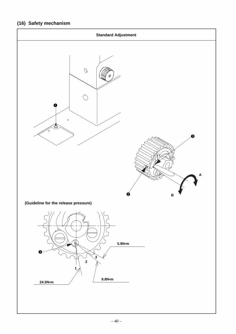
(16) Safety mechanism
(Guideline for the release pressure)
A
B
5.9N•m
9.8N•m24.5N•m
1
23
Standard Adjustment

– 41 –
When the release torque is too high:o The hook, lower shaft gears, and
such parts may be broken.When the release torque is too low:o Since the safety device is easily
actuated, smooth sewing workmay be disturbed.
The safety device will be actuated if unreasonable forces are exerted onthe lower shaft and others during operation.If the safety device is actuated, no power is transmitted to the lower shaftand the hook does not rotate even when the hand wheel is turned. Insuch a case, the lower shaft sprocket only makes idling.
o Method of resetting:1. Check the moving section of the sewing machine to look for the rea-
son why the safety device has been actuated. Remove the possiblecause.
2. Pressing the push button switch that is located on the top face ofthe bed. Strongly turn the hand wheel by hand in the reverse direc-tion.
3. When the "click" sound is heard and the hand wheel cannot be turnedany more, this is the sign for the completion of the resetting work forthe safety device.
o Adjustment of the safety device actuating torque:1. Let the sewing machine fall down.2. Loosen the setscrew (1 position) that is located on the outer pe-
riphery of the lower shaft sprocket, and turn the release pressureadjuster pin to adjust the release torque.
3. Fix the release pressure adjuster pin by means of the setscrew (1 position).
(Guideline for the release pressure)When the direction of the slot of the release pressure adjuster pin is located near the position specified below, it corresponds to therelease pressure in that case.o 24.5N•m : First tooth crest of the sprocketo 9.8N•m : In the center between the second and third tooth roots
of the sprocketo 5.9N•m : Third tooth crest of the sprocket
This value is set at 9.8N•m at the time of shipment from thefactory.
Adjustment Procedures Results of Improper Adjustment

– 42 –
(17) Reverse feed cylinder and condensation cylinder
7 to 8mm
6.5 to 7.5mm
Standard Adjustment

– 43 –
o PLC-1710-7, 1760-7 onlyo Reverse feed cylinder1. Loosen the window plate setscrews (4 positions) located behind
the sewing machine. Remove the window plate and the windowplate gasket .
2. Loosen the window plate setscrews (5 positions) and remove thewindow plate and the window plate gasket .
3. Loosen the nut .4. Adjust the distance to 7 to 8mm between the end face of the cylinder
shaft and the cylinder connecting screw .5. Tighten the nut .6. Install the window plate and the window plate gasket with the
window plate setscrews (5 positions).7. Install the window plate and the window plate gasket with the
window plate setscrews (4 positions).(Caution) When installing the window plate and the window plate
gasket in the sewing machine, the fork section of thereverse feed link has to be entered in the stepped partof the hinge screw that is mounted on the feed adjusterrod .
o Condensation cylinder1. Loosen the cylinder setscrews (2 positions) and remove the cylin-
der from the window plate .2. Loosen the nut .3. Adjust the distance to 6.5 to 7.5mm between the end face of the
cylinder shaft and the condense cylinder screw .4. Tighten the nut .5. Mount the cylinder on the window plate by means of the set-
screws (2 positions).
o If it is not entered in the hingescrew , reverse feed stitchesmay fail to be obtained.
o If the distance between thecylinder and the condensecylinder screw deviates fromthe specified value, there may bea failure in thread trimming.
Adjustment Procedures Results of Improper Adjustment

– 44 –
(18) Thread trimming device (PLC-1710-7, 1760-7)
1) Adjusting the height of the moving knife
0.8±
0.1m
m
Standard Adjustment

– 45 –
1. Let the sewing machine fall down.2. Loosen the rocking arm (R) tightening screw and the rocking arm
(L) tightening screw (1710-7: only).3. Raise the sewing machine.4. Loosen the moving knife installing base setscrews (1710-7: 2 po-
sitions, 1760-7: 4 positions).5. Move the moving knife installing base vertically so that a clear-
ance of 0.8 ± 0.1mm can be secured between the inner hook andthe bottom face of the moving knife .
6. Tighten the moving knife installing base setscrews (1710-7: 2 po-sitions, 1760-7: 4 positions).
7. Let the sewing machine fall down.8. Tighten the rocking arm (R) tightening screw and the rocking arm
(L) tightening screw (1710-7: only).In this case, refer to 3.-(18) –8), -9) Adjusting the position of the mov-ing knife (Right), (Left).
When the clearance is too much:o There will be a failure in clamp-
ing the needle thread or the bob-bin thread at the time of threadtrimming.
When the clearance is too less:o The moving knife may come in
contact with the bobbin.
Adjustment Procedures Results of Improper Adjustment
– 46 –
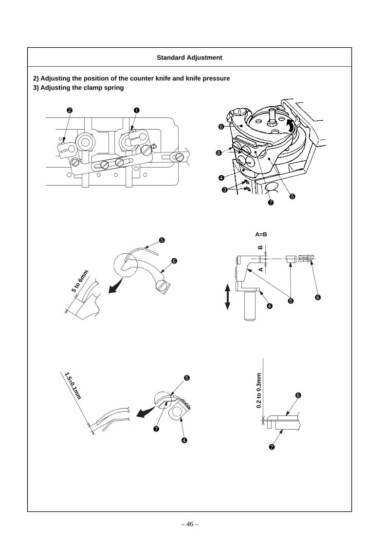
2) Adjusting the position of the counter knife and knife pressure3) Adjusting the clamp spring
5 to
6m
m
AB
A=B
1.5±0.1mm
0.2
to 0
.3m
m
Standard Adjustment

– 47 –
1. Let the sewing machine fall down.2. Loosen the rocking arm (R) tightening screw and the rocking arm
(L) tightening screw (1710-7: only).3. Raise the sewing machine.4. Loosen the counter knife installing base setscrews (1710-7: 2 po-
sitions, 1760-7: 4 positions).5. Turn the moving knife by hand and move the counter knife install-
ing base so that the contact position between the blade tip of thecounter knife and the moving knife can be maintained 5 to6mm from the tip of the moving knife.At that time, adjust the vertical positioning of the counter knife install-ing base so that the blade center of the counter knife coincideswith that of the moving knife .
6. Tighten the counter knife installing base setscrews (1710-7: 2 po-sitions, 1760-7: 4 positions).
7. Tighten the rocking arm (R) tightening screw and the rocking arm(L) tightening screw .In this case, refer to 3.-(18) –8), -9) Adjusting the position of the mov-ing knife (Right), (Left).
(Caution) The knife pressure should be kept as low as possible.
1. Let the sewing machine fall down.2. Loosen the rocking arm (R) tightening screw and the rocking arm
(L) tightening screw (1710-7: only).3. Raise the sewing machine.4. Move the moving knife by hand in the direction of the arrow until
the clamp spring can be seen.5. Loosen the clamp spring setscrews (1710-7: 2 positions, 1760-7:
4 positions).6. Adjust the position of the clamp spring so that a clearance of 1.5 ±
0.1mm can be secured between the counter knife and the clampspring .At that time, adjustments should be carried out so that a clearance of0.2 to 0.3mm can be secured between the bottom face of the movingknife and the top face of the clamp spring .
7. Tighten the clamp spring setscrews (1710-7: 2 positions, 1760-7:4 positions).
8. Tighten the rocking arm (R) tightening screw and the rocking arm(L) tightening screw (1710-7: only).In this case, refer to 3.-(18) –8), -9) Adjusting the position of the mov-ing knife (Right), (Left).
When the knife pressure is toomuch:o An excessively high burden is
generated around the blade sec-tions of the counter knife andthe moving knife . This can re-sult in the reduction of knife’s op-erational life.
When the knife pressure is too less:o Poor thread trimming may occur.
When the clearance is too much:o Since it is difficult to clamp the
trimmed bobbin thread after thecompletion of thread trimmingwork, stitch skipping may becaused at the beginning of sew-ing.
When the clearance is too less:o Since the clamping force is too
strong for the trimmed bobbinthread after the completion ofthread trimming work, stitch skip-ping may be caused at the be-ginning of sewing.
o When the moving knife inter-feres with the clamp spring ,this clamp spring may be bro-ken.
Adjustment Procedures Results of Improper Adjustment

– 48 –
4) Adjust the thread trimming cam position
Close contact
0.1 to 0.2mm
Standard Adjustment
Close contact Close contact

– 49 –
1. Let the sewing machine fall down.2. Loosen the connecting plate setscrews (2 positions) of the thread
trimming driving joint plate.3. In the state that the thread trimmer driving plate is pressed in the
direction of the arrow to keep contact with the vertical fitting basis ,move the thread trimmer roller arm so that a clearance of 0.1 to0.2mm can be secured between the thread trimmer driving plate and the cam roller .
4. While the state of 3. above is kept as it is, loosen the thread trimmercam setscrews (2 positions). Keep a close contact between theend face of the thread trimmer cam and the cam roller , andtemporarily tighten the thread trimmer cam setscrews (2 positions).(These setscrews are temporarily tightened because timing adjust-ments are needed for the thread trimmer cam afterwards.)
5. Loosen the safety device disc setscrews (2 positions). Let thesafety device disc keep a close contact with the thread trimmercam and firmly tighten the safety device disc setscrews (2 po-sitions).
6. In the state that the thread trimmer roller arm is pressed in thedirection of the arrow and that the vertical fitting basis , the threadtrimmer driving plate , and the cam roller are keeping contactwith each other, tighten the thread trimmer driving joint plate setscrews
(2 positions).In this case, refer to 3.-(18) –6) Connection of the rocking arm andthe thread trimmer roller arm.
When no clearance is secured be-tween the cam roller and the driv-ing plate:o The thread trimmer cam in-
terferes with the cam roller and this can be a cause of break-age or machine lock.
When a large clearance is securedbetween the cam roller and the driv-ing plate:o The cam roller enters the
thread trimmer cam duringmachine operation and this canbe a cause of machine lock.
Adjustment Procedures Results of Improper Adjustment

– 50 –
5) Timing adjustment for the thread trimming cam
Standard Adjustment
Close contactClose contact
6) Connection of the rocking arm and the thread trimmer roller arm
Close contact
Close contact
– 51 –
5) Timing adjustment for the thread trimming cam
1. Let the sewing machine fall down.2. Loosen the thread trimmer cam setscrews (2 positions) that have
been temporarily tightened during the positional adjustment of thethread trimmer cam .
3. Turn the hand wheel to secure a coincidence between the engravedmarker point of the arm and the red engraved marker point ofthe hand wheel.
4. In the state that the thread trimmer cam and the safety device disc are keeping a close contact with each other, turn the thread trim-
mer cam by hand until the thread trimmer cam roller comes tocontact the R section at the beginning of the cam groove in the threadtrimmer cam .
5. Firmly tighten the thread trimmer cam setscrews (2 positions).6. Raise the sewing machine.(Caution) Confirm that the end face of the thread trimmer cam
and that of the safety device disc are keeping a closecontact with each other.
6) Connection of the rocking arm and the thread trimmer roller arm1. Let the sewing machine fall down.2. Loosen the connecting plate setscrews (2 positions) of the thread
trimming driving joint plate.3. Keep the close contact with the rocking arm and the thread trim-
ming stopper .4. Push the thread trimmer roller arm in the direction of the arrow
and let it contact with the thread trimmer cam roller , the threadtrimmer driving plate , and the vertical fitting basis .
5. Tighten the connecting plate setscrews of the thread trimming driv-ing joint plate.
6. Raise the sewing machine.
When the timing for thread trimmingis too slow:o Operation of thread trimming is
not finished even at the upperstop position. This can be acause of thread t r immingdeficiency.
When the timing for thread trimmingis too fast:o It can be a cause of thread
trimming deficiency.o The remaining length of the
needle thread becomes short. Inthis case, the needle thread maycome off the needle after threadtrimming or at the beginning ofsewing.
o This can be a cause of stitchskipping at the beginning of sew-ing.
Adjustment Procedures Results of Improper Adjustment

– 52 –
7) Thread trimming solenoid
8) Adjusting the position of the moving knife (Right) (PLC-1710-7, 1760-7)
0.3mm
to 0.5mm
Contact
Contact
(9 to 10mm
)
0.05
to 0.15mm
A
B
C
Fig. A
Standard Adjustment

– 53 –
7) Thread trimming solenoid1. Let the sewing machine fall down.2. Loosen the solenoid fitting plate setscrews (2 positions).3. Loosen the solenoid connecting arm setscrews (2 positions).4. Tighten the solenoid fitting plate setscrews (2 positions) in the
position where the solenoid shaft can move smoothly while thesolenoid shaft is moved in the direction of A or B.
5. Push the thread trimmer roller arm in the direction of C and let itcontact with the cam roller , the thread trimmer driving plate ,and the vertical fitting basis .
6. While the state of 5. above is kept as it is, move the solenoid shaft in the direction of A or B so that a clearance of 0.05 to 0.15mm can besecured between the end face of the thread trimmer solenoid andthe plunger stopper . Since then, tighten the solenoid connectingarm setscrews (2 positions).
(Confirmation) 1. Manually actuate the thread trimmer and confirm thata clearance of 0.05 to 0.15mm has been secured be-tween the plunger stopper of the thread trimmersolenoid and the thread trimmer solenoid whenthe moving knife returns to its initial position.
2. For initial positions of the moving knife, refer to 3.-(18) –8), -9) Adjusting the position of the moving knife(Right), (Left).
8) Adjusting the position of the moving knife (Right) (PLC-1710-7,1760-7)
1. Let the sewing machine fall down.2. Loosen the rocking arm (R) tightening screw and the rocking arm
(L) tightening screw (1710-7: only).3. Adjust the moving knife to its initial position (where the blade tip of
the counter knife is protruded by 0.3 to 0.5mm from the tip of themoving knife (Fig. A)).
4. Push the rocking arm (R) in the direction of the arrow and tightenthe tightening screw (1 position) while the thread trimmer stopper
keeps contact with the rocking arm (R).5. Raise the sewing machine.(Caution) 1. During adjustments, confirm that the initial position of
the moving knife has already been adjusted.2. In regard to the adjustment of the moving knife (L)
for the PLC-1760-7, refer to 3.-(18) –9), Adjusting theposition of the moving knife (L).
When the clearance is too much:o The operational range of the
thread trimmer solenoid isnarrowed and this can be acause of machine lock.
When no clearance is secured:o The plunger stopper may be
broken.
o If any positional adjustment hasbeen made inadequately, threadtrimmer malfunction will occur.
Adjustment Procedures Results of Improper Adjustment

– 54 –
9) Adjusting the position of the moving knife (Left) (PLC-1760-7 only)
0.3 to 0.5mm
4.5
to 5
.5m
m
Contact
A°B°
X Y
Lmm
Worker side
Standard Adjustment
– 55 –
(Caution) Prior to adjustments, refer to 3.-(18) –8), Adjusting theposition of the moving knife (R) and confirm that theposition of the moving knife (R) has been adjustedcorrectly.
1. Let the sewing machine fall down.2. Loosen the rocking arm (left) tightening screw (1 position).3. Loosen the setscrewa (2 positions) of the thread trimmer driving
joint plate.4. Raise the sewing machine.5. Move the moving knife by hand and adjust it to the position where
the tip of the moving knife is withdrawn by 0.3 to 0.5mm from theblade tip of the counter knife .
6. Let the sewing machine fall down.7. Adjust the center-to-center distance (Lmm) between the right and left
thread trimmer driving jpint plate so that the gradient (A°) of therocking arm (R) when it is pushed in the direction of [Y] becomesidentical with that (B°) of the rocking arm (L). When this condition isassumed, tighten the setscrews (2 positions) of the thread trim-mer driving joint plate.
8. Tighten the rocking arm (L) tightening screw (1 position) while therocking arm (R) is pushed in the direction of [Y].
9. Turn the hand wheel by hand to move the moving knife to its frontmost position while the rocking arm (R) is pushed in the directionof [X].
10. Confirm that the distance has attained 4.5 to 5.5mm between the tipof the moving knife and the end face of the throat plate .If this distance has not attained 4.5 to 5.5mm, make adjustments inthe procedures specified below.o When the distance is greater than 4.5 to 5.5mm:
1) Loosen the rocking arm (left) tightening screw (1 position).2) Loosen the setscrews (2 positions) of the thread trimmer driv-
ing joint plate.3) Shorten the center-to-center distance (Lmm) between two thread
trimmer driving joint plates .4) Refer to 5.5) Refer to 9.6) Refer to 10.
o When the distance is shorter than 4.5 to 5.5mm:1) Loosen the rocking arm (left) tightening screw (1 position).2) Loosen the connecting plate setscrews (2 positions) of the
thread trimmer driving joint plate.3) Lengthen the center-to-center distance (Lmm) between two
thread trimmer driving joint plates .4) Refer to 5.5) Refer to 9.6) Refer to 10.
11. Raise the sewing machine.
Adjustment Procedures Results of Improper Adjustment

– 56 –
(19) Alternate vertical dial (PLC-1710-7, 1760-7)
1) Mounting position of the alternate vertical amount detector switch
Sewing speed
Alternate Stitches: Stitches:vertical 6mm or Over 6mm andamount below 9mm or below
~ 2.5mm or below 2500rpm 1800rpm
Over 2.5mm and4mm or below
Over 4mm and4.75mm or below
Over 4.75mm and6.5mm or below
2200rpm 1800rpm
1800rpm 1800rpm
1600rpm 1600rpm
Graduations of the Switch (Top) Switch (Bottom)alternate vertical dial (Red & Green lines) (White & Black lines)
1 to 2.5 OFF OFF
2.625 to 4 OFF ON
4.125 to 4.75 ON ON
4.875 to 6.5 ON OFF
Alternate vertical dial
Detector switch of alter-nate vertical amount Top cover
Pin
Spring
Hole in Section A
8±0.1mm
Bushing
Embossedsection
White Black
Red Green
Standard Adjustment

– 57 –
o PLC-1710-7, 1760-71. Turn the alternate vertical dial to adjust the graduations [1] to the
marking (embossed section) of the top cover.2. Loosen the alternate vertical dial setscrew (1 position) and re-
move the alternate vertical dial. Be careful in this case that there is aset of pin and spring inserted in the hole of Section A.
3. Loosen the mounting screws (2 positions) of the alternate verticalamount detector switch and then tighten these alternate verticalamount detector switch mounting screws (2 position) after the dis-tance has been adjusted to 8 ± 0.1mm between the bush inner diam-eter and the end face of the switch main body.
4. Let the graduations [1] of the alternate vertical dial coincide with theembossed section of the top cover and mount this alternate verticaldial after inserting the set of pin and spring has been inserted in thehole of Section A. Since then, tighten the alternate vertical dial set-screw .
(Caution) 1. If the position of the alternate vertical amount detectorswitch has been changed, confirm whether the cor-rect relationship is secured between the alternate ver-tical dial and the number of revolutions.
2. The PLC-1760L is provided with the alternate verticaldial. However, no alternate vertical amount detectorswitch is mounted.
o There may be no changes in thesewing speed even though thealternate vertical dial is turned.
Adjustment Procedures Results of Improper Adjustment
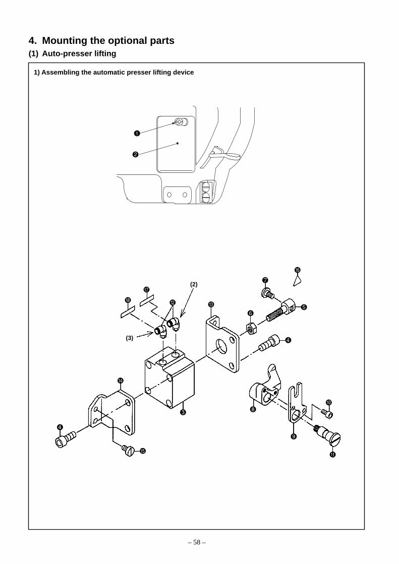
– 58 –
1) Assembling the automatic presser lifting device
4. Mounting the optional parts(1) Auto-presser lifting
(3)
(2)

– 59 –
(Caution) Confirm that the motor power supply is turned off.
1. Loosen the side cover setscrew (1 position) and remove the side cover .2. Install the elbow on the Auto-presser lifting cylinder .3. Stick the wire marks and to the elbow .
(Elbow [2] is positioned on the face side and Elbow [3] on the hand wheel side.)4. Mount the hinge screw on the cylinder connecting screw .
At that time, Lock Tight 243 shall be applied after the degreasing of the threaded section of the hinge screw.5. Install the cylinder connecting screw and the nut on the Auto-presser lifting cylinder
(Guideline) Tighten the nut after the distance has been adjusted to 24mm between the piston rod end faceof the Auto-presser lifting cylinder and the end face of the cylinder connecting screw .
6. Tighten the cylinder stay (front) and cylinder stay (rear) on the Auto-presser lifting cylinder with thesetscrews (each 2 positions).
7. Mount the Auto-presser lifting cylinder , which has been assembled as per 6. above, on the arm by meansof the setscrews (4 positions).
8. Assemble the Auto-presser lifting lever B in the Auto-presser lifting lever A .(Insert the Auto-presser lifting lever shaft and tighten it with the hexagon head bolts (2 positions).)
9. Mount the Auto-presser lifting lever A , which has been assembled as per 8. above, on the arm by meansof the Auto-presser lifting lever shaft .When the Auto-presser lifting lever A is mounted on the arm, the hinge screw is required to settle in thegroove of the Auto-presser lifting lever B .Apply grease to the hinge section of the Auto-presser lifting lever shaft and apply Lock Tight 243 to thethreaded section after the degreasing.
Automatic presser lifter device: Deletion parts list
Automatic presser lifter device: Additional parts list (List A)
No. Part No. Names of part Q'ty
PA400150100 Auto-presser lifting cylinder 1
SM6082002SP Setscrew 4
21356506 Cylinder connecting screw 1
NM6080001SE Nut 1
SD0720331SP Hinge screw 1
21388509 Auto-presser lifting lever A 1
21356803 Auto-presser lifting lever B 1
SM6051002TP Hexagon socket head cap screw 2
21356704 Presser auto-lifting lever shaft 1
PJ304065102 Elbow 2
21356308 Cylinder stay (front) 1
21356407 Cylinder stay (rear) 1
SS6151040SP Setscrew 4
CM300200001 Finger injury caution seal 1
HX00295000A Wire mark (2) 1
HX00295000B Wire mark (3) 1
No. Part No. Names of part Q'ty
SS4110815SP Side cover setscrew 1
21331806 Side cover 1

– 60 –
2) Assembly of the air device
B
A
Red : CN1-2
Black : CN1-1
21
CN1
CN50-1

– 61 –
1. Install the air device (P) (Assy) on the table with the wood screw .2. Install the filter regulator (Assy) on the table with wood screw .3. Insert the connector (CN50-1) of the air device (P) (Assy) in the (CN50-1) block of the motor panel.
(Motor: For SC-510)4. Connect the air device (P) (Assy) and the filter regulator (Assy) through an air hose .5. Connect the air device (P) (Assy) and the auto-presser lifting cylinder through an air hose.
At that time, the elbow with the same number shall be connected to the joint.
6. Check the function of the auto-presser lifting device.1) Turn the motor power supply ON.2) Connect the air supply pipe to the air joint .3) Actuate the auto-presser lifting device to lift the presser foot and confirm whether a clearance of 16 ±
0.5mm is secured between the bottom face of the presser foot and the top face of the throat plate. Formore details, refer to 3.-(8)-2) using a knee lifter.
4) If any adjustment is required, loosen the nut and the cylinder shaft .o Turned in the direction A Increase in the lifting amount of the presser footo Turned in the direction B decrease in the lifting amount of the presser foot
5) After adjustments, tighten the nut .7. When the presser foot is lowered, confirm whether a clearance of 0.5 to 1.5mm is secured between the auto-
presser lifting lever A and the thread tension releasing plate.For more details, refer to 3.-(8)-3) Automatic presser lifting.
Automatic reverse feed device: Additional parts list (List B)
No. Part No. Names of part Q'ty
40038906 Air device (P) (Assy) 1
SK3415001SE Wood screw 4
40038722 Filter regulator (Assy) 1
SK3482501SE Wood screw 2

– 62 –
1) Removing the window plate
2) Removing the reverse feed lever (PLC-1710, 1760)
3) Installing the reverse feed lever (PLC-1710, 1760)
(2) Automatic reverse feed device

– 63 –
(Caution) 1. The auto-reverse feed device can be mounted only on the sewing machine that is equippedwith the auto-presser lifting device.
2. Prior to the work, confirm that the motor power supply has been turned OFF.3. This work should be carried out in the state that the air pressure in the regulator is zero.
1) Removing the window plate1. Remove the window plate B setscrews (5 positions), which are located in the arm opposite the worker
side.2. Remove the window plate B and the window plate gasket B .
2) Removing the reverse feed lever (PLC-1710, 1760)1. For the PLC-1710 and 1760, loosen each setscrew of the belt cover to remove the belt cover. Then, loosen
the reverse feed lever setscrews (2 positions) to remove the reverse feed lever .
3) Installing the reverse feed lever (PLC-1710, 1760)1. Mount the lever spring hanger on the removed reverse feed lever , using the setscrew (1 position).2. Install the reverse feed lever stopper on the arm with the setscrew (1 position).3. Mount the lever return spring hanger on the arm.4. The lever spring hanger has been mounted on the reverse feed lever as per 1. above. Insert this lever
in the reverse feed lever shaft and mount the reverse feed shaft link by means of a setscrew (1position).(This mounting work shall be done so that the embossed section of the reverse feed shaft link can enterthe bottom side of the reverse feed lever .)
5. Hook the lever return spring on the lever spring hanger and the lever return spring hanger .6. Adjust the position of the reverse feed lever .
For more details, refer to 3.-(15) Position of reverse feed lever.
Automatic reverse feed device: Deletion parts list
No. Part No. Names of part Q'ty
22656003 Lever spring hanger 1
SS4120615SP Setscrew 1
22952501 Reverse feed lever stopper 1
SS7111810SP Setscrew 1
10120004 Lever return spring hanger 1
22656102 Reverse feed shaft link 1
SS7120760SP Pushing screw 1
13515606 Lever return spring 1
No. Part No. Names of part Q'ty
21331806 Window plate B 1
SS6120930SP Reverse feed lever setscrew 2
Automatic reverse feed device: Additional parts list (List C)

– 64 –
4) Installing the automatic reverse feed device
5) 5-operation switch mounting
A

– 65 –
4) Installing the automatic reverse feed device1. Install the automatic reverse feed device together with the window plate gasket B from which the window
plate (Assy) has been removed, using the window plate setscrews (5 positions).At the time of installation, Section A of the window plate (Assy) shall be entered in the hinge screw of the
feed adjusting rod that is located in the arm.
For more details, refer to 3.-(17) Reverse feed cylinder and condensation cylinder.
5) 5-operation switch mounting
1. Mount the 5-operation switch (Assy) on the arm by means of the setscrews (2 positions).2. The cord of the 5-operation switch (Assy) shall be fixed to the rear side of the arm by means of the cable
clips and setscrews (fixing positions: to ) as well as cord stopper fittings and setscrews (fixing positions: and )
Automatic reverse feed device: Additional parts list (List D)
No. Part No. Names of part Q'ty Remarks
40024849 5-operation switch (Assy) 1
SS7110840SP Setscrew 2
HX00123000A Cable clip 3 Fixing positions: to
SS4110815SP Setscrew 3 Setscrews for to
D2112555B00 Cord stopper fittings 2 Fixing positions: and
SS6111140SP Setscrews for cord stopper fittings 2 Setscrews for and
Automatic reverse feed device: Additional parts list (List E)
No. Part No. Names of part Q'ty
40040660 Window plate (Assy) 1
40043357 Window plate H (1)
PA320150200 Reverse feed cylinder (1)
SM6061602TP Setscrew (2)
WP0641601SD Washer (2)
21348602 Cylinder connecting screw (1)
NM6060003SC Nut (1)
21348503 Reverse feed link mounting base (1)
SS7151210SP Setscrew (2)
21348701 Reverse feed link (1)
SD0800352SP Hinge screw (2)
PJ301065104 Straight joint (1)
PX015101000 Muffler (1)
21349105 Cylinder gasket (1)
HX002950000 Wire mark (1) (1)

– 66 –
6) Installation of the air-related devices
A
A
10
5 1
CN20
6
CN1
CN20
5-operation switch

– 67 –
Solenoid valve already
attached
Solenoid valve newlyattached
1. Using the setscrews (2 positions), mount the solenoid valve (Assy) on the solenoid valve (P) (Assy) that is presently used.In this case, a cover is mounted on the solenoid valve (P) (Assy) by means of the setscrews (2 positions).Therefore, these setscrews (2 positions) and the cover must be removed first of all.
2. Loosen the setscrews (2 positions) and mount the replaced stop plug on the one-touch joint .3. Disconnect the connector (CN1) from the solenoid valve (P) (Assy) .4. Insert the cords to , which are extended from the solenoid valve (P) (Assy) and the solenoid valve
(Assy) , in the connector (CN20) .(The cord of the solenoid valve (P) (Assy) shall be passed through the tube , and then inserted in theconnector (CN20) .)
5. Using the relay cords, make connections among SC-510 (inside the front cover), the 5-operation switch, andthe solenoid valve (P) (Assy).
6. For the one-touch joint mounted as per 2. above and the straight joint of the reverse feed cylinder, connectthem through the air hose (Assy) (for BT).
7. Check the function of the automatic reverse feed device.1) Connect the pipe of the air supply source and turn the motor power supply ON.2) Press the leftmost switch of the 5-operation switch and confirm that the automatic reverse feed device
is actuated.
No. Part No. Names of part Q'ty Remarks
40040419 Solenoid valve (Assy) 1
HK034610100 Connector 1 CN20 connector
40024864 Relay cord 1
40040671 Air hose (Assy) (for BT) 1
Automatic reverse feed device: Additional parts list (List F)
Cord : (Red) → CN20-7
Cord : (Black) → CN20-2
Cord : (Red) → CN20-8
Cord : (Black) → CN20-3
(Solenoid valve (P) (Assy) )
(Solenoid valve (Assy) )

– 68 –
1) Installing the DL device
(3) DL device (PLC-1760L only)
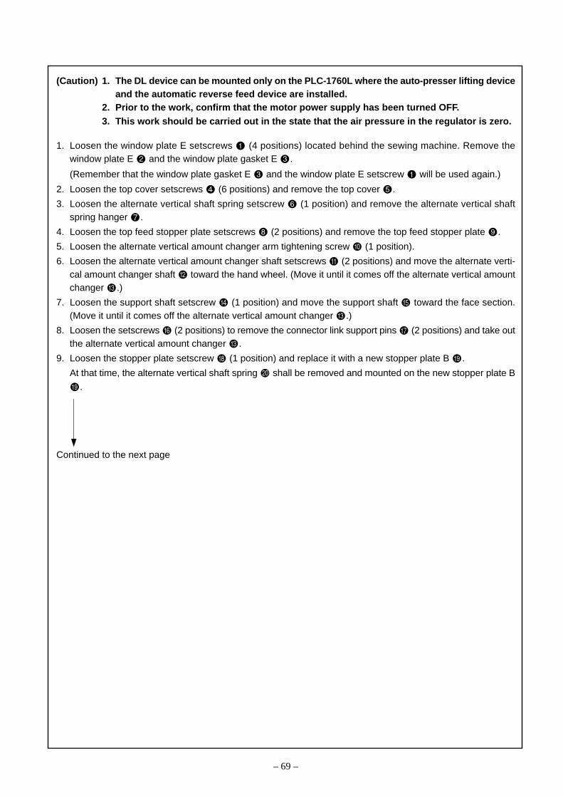
– 69 –
(Caution) 1. The DL device can be mounted only on the PLC-1760L where the auto-presser lifting deviceand the automatic reverse feed device are installed.
2. Prior to the work, confirm that the motor power supply has been turned OFF.3. This work should be carried out in the state that the air pressure in the regulator is zero.
1. Loosen the window plate E setscrews (4 positions) located behind the sewing machine. Remove thewindow plate E and the window plate gasket E .
(Remember that the window plate gasket E and the window plate E setscrew will be used again.)
2. Loosen the top cover setscrews (6 positions) and remove the top cover .
3. Loosen the alternate vertical shaft spring setscrew (1 position) and remove the alternate vertical shaftspring hanger .
4. Loosen the top feed stopper plate setscrews (2 positions) and remove the top feed stopper plate .
5. Loosen the alternate vertical amount changer arm tightening screw (1 position).
6. Loosen the alternate vertical amount changer shaft setscrews (2 positions) and move the alternate verti-cal amount changer shaft toward the hand wheel. (Move it until it comes off the alternate vertical amountchanger .)
7. Loosen the support shaft setscrew (1 position) and move the support shaft toward the face section.(Move it until it comes off the alternate vertical amount changer .)
8. Loosen the setscrews (2 positions) to remove the connector link support pins (2 positions) and take outthe alternate vertical amount changer .
9. Loosen the stopper plate setscrew (1 position) and replace it with a new stopper plate B .
At that time, the alternate vertical shaft spring shall be removed and mounted on the new stopper plate B
.
Continued to the next page

– 70 –
1) Installing the DL device
A
A
B
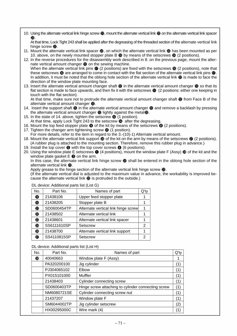
– 71 –
10. Using the alternate vertical link hinge screw , mount the alternate vertical link on the alternate vertical link spacer.
At that time, Lock Tight 243 shall be applied after the degreasing of the threaded section of the alternate vertical linkhinge screw .
11. Mount the alternate vertical link spacer , on which the alternate vertical link has been mounted as per10. above, on the newly mounted stopper plate B by means of the setscrews (2 positions).
12. In the reverse procedures for the disassembly work described in 8. on the previous page, mount the alter-nate vertical amount changer on the sewing machine.When the alternate vertical link pins (2 positions) are fixed with the setscrews (2 positions), note thatthese setscrews are arranged to come in contact with the flat section of the alternate vertical link pins .In addition, it must be noted that the oblong hole section of the alternate vertical link is made to face thedirection of the window plate mounting face.
13. Insert the alternate vertical amount changer shaft in the alternate vertical amount changer so that itsflat section is made to face upwards, and then fix it with the setscrews (2 positions: either one keeping intouch with the flat section).At that time, make sure not to protrude the alternate vertical amount changer shaft from Face B of thealternate vertical amount changer .
14. Insert the support shaft in the alternate vertical amount changer and remove a backlash by pressingthe alternate vertical amount changer lightly against the metal .
15. In the state of 14. above, tighten the setscrew (1 position).At that time, apply Lock Tight 243 to the setscrew after the degreasing.
16. Mount the top feed stopper plate of the kit by means of the setscrews (2 positions).17. Tighten the changer arm tightening screw (1 position).
For more details, refer to the item in regard to the 3.-(10)-1) Alternate vertical amount.18. Mount the alternate vertical link support of the kit on the arm by means of the setscrews (2 positions).
(A rubber plug is attached to the mounting section. Therefore, remove this rubber plug in advance.)19. Install the top cover with the top cover screws (6 positions).20. Using the window plate E setscrews (4 positions), mount the window plate F (Assy) of the kit and the
window plate gasket E on the arm.In this case, the alternate vertical link hinge screw shall be entered in the oblong hole section of thealternate vertical link .Apply grease to the hinge section of the alternate vertical link hinge screw .(If the alternate vertical dial is adjusted to the maximum value in advance, the workability is improved be-cause the alternate vertical link is protruded to the outside.)
DL device: Additional parts list (List G)
No. Part No. Names of part Q'ty21438106 Upper feed stopper plate 121438205 Stopper plate B 1SD0600454TP Alternate vertical link hinge screw 121438502 Alternate vertical link 121438601 Alternate vertical link spacer 1SS6111610SP Setscrew 221438700 Alternate vertical link support 1SS4110815SP Setscrew 2
DL device: Additional parts list (List H)
No. Part No. Names of part Q'ty40040663 Window plate F (Assy) 1PA320200100 Jig cylinder (1)PJ304065102 Elbow (1)PX015101000 Muffler (1)21438403 Cylinder connecting screw (1)SD0600403TP Hinge screw attaching to cylinder connecting screw (1)NM6080721SE Cylinder connecting screw nut (1)21437207 Window plate F (1)SM6044002TP Jig cylinder setscrew (2)HX00295000C Wire mark (4) (1)

– 72 –
2) Installation of the air-related devices
A
A
(BT)
(AK)
CN20
10 6
5 1
CN20
5-operation switch
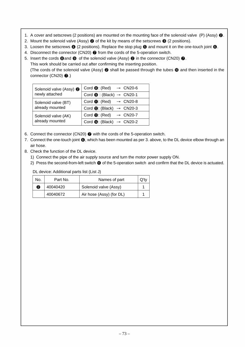
– 73 –
1. A cover and setscrews (2 positions) are mounted on the mounting face of the solenoid valve (P) (Assy) .2. Mount the solenoid valve (Assy) of the kit by means of the setscrews (2 positions).3. Loosen the setscrews (2 positions). Replace the stop plug and mount it on the one-touch joint .4. Disconnect the connector (CN20) from the cords of the 5-operation switch.5. Insert the cords and of the solenoid valve (Assy) in the connector (CN20) .
This work should be carried out after confirming the inserting position.(The cords of the solenoid valve (Assy) shall be passed through the tubes and then inserted in theconnector (CN20) .)
6. Connect the connector (CN20) with the cords of the 5-operation switch.7. Connect the one-touch joint , which has been mounted as per 3. above, to the DL device elbow through an
air hose.8. Check the function of the DL device.
1) Connect the pipe of the air supply source and turn the motor power supply ON.2) Press the second-from-left switch of the 5-operation switch and confirm that the DL device is actuated.
No. Part No. Names of part Q'ty
40040420 Solenoid valve (Assy) 1
40040672 Air hose (Assy) (for DL) 1
DL device: Additional parts list (List J)
Cord : (Red) → CN20-6
Cord : (Black) → CN20-1
Cord : (Red) → CN20-8
Cord : (Black) → CN20-3
Cord : (Red) → CN20-7
Cord : (Black) → CN20-2
Solenoid valve (Assy) newly attached
Solenoid valve (BT)already mounted
Solenoid valve (AK)already mounted
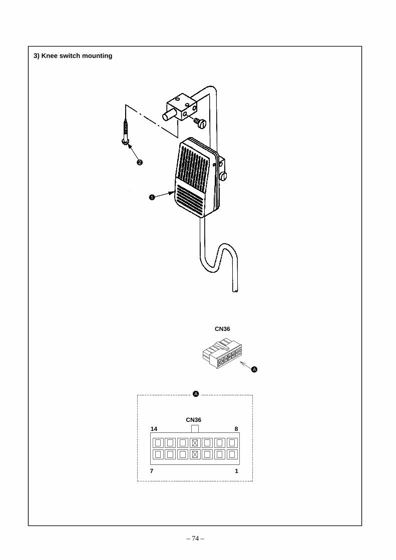
– 74 –
3) Knee switch mounting
A
A
CN36
14 8
7 1
CN36

– 75 –
1. Mount the knee switch (Assy) on the bottom face of the table by means of the wood screws (2 pcs.).2. Insert the cords of the knee switch (Assy) in the relay cord connector (CN36: 14 pins connector, white).
(Cord (white) → Insert to Pin No. [4], Cord (black) → Insert to Pin No. [11])3. Set up the motor (SC-510).
For more details, refer to the SC-510 Instruction Manual, [Method of Functional Setup].(1) Pressing the [+] button that is located on the motor panel, turn the power supply ON.(2) Press [↓] and adjust the Setup No. to 24.(3) Press the [+] or [–] button and make setting at [2] or [3].
• In the case of Setting [2], the DL is turned ON with the switch turned ON and the DL is turned OFF withthe switch turned OFF.
• In the case of Setting [3], the DL is turned ON with the switch turned ON and the DL is turned OFF withthe switch turned OFF and again turned ON.
(4) Press the [↓] button once in order to preserve the setting data.(5) Turn the power supply OFF.(6) Turn the power supply ON and press the knee switch Assy to check the operation.
No. Part No. Names of part Q'ty
40025036 Knee switch (Assy) 1
SK3514000SC Wood screw 2
DL device: Additional parts list (List K)
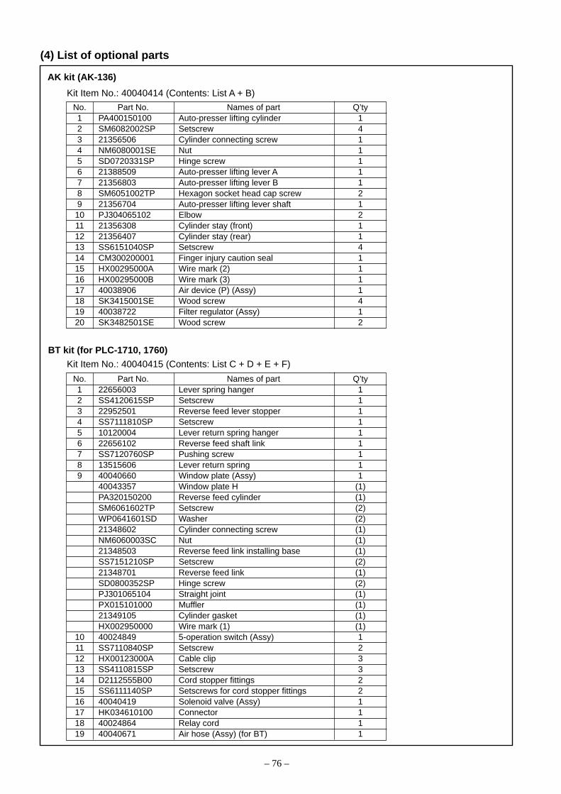
– 76 –
AK kit (AK-136)
(4) List of optional parts
Kit Item No.: 40040414 (Contents: List A + B)
No. Part No. Names of part Q’ty1 PA400150100 Auto-presser lifting cylinder 12 SM6082002SP Setscrew 43 21356506 Cylinder connecting screw 14 NM6080001SE Nut 15 SD0720331SP Hinge screw 16 21388509 Auto-presser lifting lever A 17 21356803 Auto-presser lifting lever B 18 SM6051002TP Hexagon socket head cap screw 29 21356704 Auto-presser lifting lever shaft 110 PJ304065102 Elbow 211 21356308 Cylinder stay (front) 112 21356407 Cylinder stay (rear) 113 SS6151040SP Setscrew 414 CM300200001 Finger injury caution seal 115 HX00295000A Wire mark (2) 116 HX00295000B Wire mark (3) 117 40038906 Air device (P) (Assy) 118 SK3415001SE Wood screw 419 40038722 Filter regulator (Assy) 120 SK3482501SE Wood screw 2
Kit Item No.: 40040415 (Contents: List C + D + E + F)
No. Part No. Names of part Q’ty1 22656003 Lever spring hanger 12 SS4120615SP Setscrew 13 22952501 Reverse feed lever stopper 14 SS7111810SP Setscrew 15 10120004 Lever return spring hanger 16 22656102 Reverse feed shaft link 17 SS7120760SP Pushing screw 18 13515606 Lever return spring 19 40040660 Window plate (Assy) 1
40043357 Window plate H (1)PA320150200 Reverse feed cylinder (1)SM6061602TP Setscrew (2)WP0641601SD Washer (2)21348602 Cylinder connecting screw (1)NM6060003SC Nut (1)21348503 Reverse feed link installing base (1)SS7151210SP Setscrew (2)21348701 Reverse feed link (1)SD0800352SP Hinge screw (2)PJ301065104 Straight joint (1)PX015101000 Muffler (1)21349105 Cylinder gasket (1)HX002950000 Wire mark (1) (1)
10 40024849 5-operation switch (Assy) 111 SS7110840SP Setscrew 212 HX00123000A Cable clip 313 SS4110815SP Setscrew 314 D2112555B00 Cord stopper fittings 215 SS6111140SP Setscrews for cord stopper fittings 216 40040419 Solenoid valve (Assy) 117 HK034610100 Connector 118 40024864 Relay cord 119 40040671 Air hose (Assy) (for BT) 1
BT kit (for PLC-1710, 1760)

– 77 –
Kit Item No.: 40040469 (Contents: List D + E + F)
No. Part No. Names of part Q’ty1 40040660 Window plate (Assy) 1
40043357 Window plate H (1)PA320150200 Reverse feed cylinder (1)SM6061602TP Setscrew (2)WP0641601SD Washer (2)21348602 Cylinder connecting screw (1)NM6060003SC Nut (1)21348503 Reverse feed link installing base (1)SS7151210SP Setscrew (2)21348701 Reverse feed link (1)SD0800352SP Hinge screw (2)PJ301065104 Straight joint (1)PX015101000 Muffler (1)21349105 Cylinder gasket (1)HX002950000 Wire mark (1) (1)
2 40024849 5-operation switch (Assy) 13 SS7110840SP Setscrew 24 HX00123000A Cable clip 35 SS4110815SP Setscrew 36 D2112555B00 Cord stopper fittings 27 SS6111140SP Setscrews for cord stopper fittings 28 40040419 Solenoid valve (Assy) 19 HK034610100 Connector 110 40024864 Relay cord 111 40040671 Air hose (Assy) (for BT) 1
BT kit (for PLC-1760L)
Kit Item No.: 40040416 (Contents: List G + H + J + K)
No. Part No. Names of part Q’ty1 21438106 Upper feed stopper plate 12 21438205 Stopper plate B 13 SD0600454TP Alternate vertical link hinge screw 14 21438502 Alternate vertical link 15 21438601 Alternate vertical link spacer 16 SS6111610SP Setscrew 27 21438700 Alternate vertical link support 18 SS4110815SP Setscrew 29 40040663 Window plate F (Assy) 1
PA320200100 Jig cylinder (1)PJ304065102 Elbow (1)PX015101000 Muffler (1)21438403 Cylinder connecting screw (1)SD0600403TP Hinge screw attaching to cylinder connecting screw (1)NM6080721SE Cylinder connecting screw nut (1)21437207 Window plate F (1)SM6044002TP Jig cylinder setscrew (2)HX00295000C Wire mark (4) (1)
10 40040420 Solenoid valve (Assy) 111 40040672 Air hose (Assy) (for DL) 112 40025036 Knee switch (Assy) 113 SK3514000SC Wood screw 2
DLT kit (DL-23)
* The DL kit applicable to the PLC-1760L only
– 78 –
5. Gauge replacement for the 2-needle sewing machine
Needle bar rocking base
Needle bar rocking base fulcrum shaft
Face cover
Pin
Needle clamp
Feeding lever
Feed lever base
Feed dogThroat plate holderHook cover
Throat plate
Rockingarm (left)
Connecting link
Standard Adjustment
Rockingarm (right)
Throat plate Hook cover

– 79 –
1. Loosen the needle setscrews (2 positions) and remove the needle.2. Loosen the feed foot setscrew (1 position) and take out the feed foot.3. Loosen the presser foot setscrew (1 position) and take out the presser foot.4. Let the sewing machine fall down.5. Loosen the connecting link setscrews (2 positions). (PLC-1760-7 only)6. Remove the rocking arm (right) hinge screw (1 position).(PLC-1760-7 only)7. Loosen the rocking arm (right) tightning screw (1 position) and the rocking arm (left) tightning screw (1 position)
and remove the rocking arm (left) and the connecting link (2 pcs.).(PLC-1760-7 only)8. Loosen the hook shaft gear setscrews (6 positions).9. Loosen the lower shaft gear setscrews (4 positions) so that the lower shaft gear can move to the right and left.
In this case, make sure that the first screw of the lower shaft gear setscrews can never be disengaged from the flat faceof the lower shaft.
10. Raise the sewing machine.(Caution) For the PLC-1760-7, pay attention to the connecting link that is attached to the thread trimmer driving arm.11. Loosen the throat plate setscrews (2 positions) and remove the throat plate.12. Loosen the screws (10 positions) of the throat plate base and remove the throat plate holder.13. Loosen the screws (8 positions) of the hook shaft base cover and remove the hook shaft base cover (4 pcs.).14. Loosen the left hook shaft base setscrews (2 positions) and remove the left hook shaft base.15. Loosen the right hook shaft base setscrews (2 positions) and shift the right hook shaft base to the right in advance.16. Loosen the feed dog setscrew (1 position) to replace the feed tooth and tighten the feed dog setscrew again.
(The feed dog setscrew shall be tightened at the tightening torque of 5.39 to 6.37N•m.)17. Remove the needle bar rocking fulcrum shaft setscrew (1 position).18. Open the face cover and draw out the needle bar rocking fulcrum shaft in the direction of the arrow until the top face of
the needle bar can be seen from the top screw hole.19. Insert the accessory hexagon head wrench (2.5mm) in the needle bar through the hole of the needle bar rocking fulcrum
shaft setscrew and loosen the needle clamp setscrew (1 position) that is located in the needle bar.20. Mount the replacing needle clamp on the needle bar and tighten the needle clamp setscrew (1 position).
(In this case, the pin attached to the needle clamp shall be adjusted to the groove that is located at the bottom end of theneedle bar.)
21. Return the needle bar rocking fulcrum shaft that has been drawn out as per 18. above. Tighten the needle bar rockingfulcrum shaft setscrew (1 position).At that time, this setscrew shall be tightened until it comes in contact with the flat face of the shaft. After screw tightening,confirm that there is no thrust backlash in the needle bar rocking base.
22. After the needle has been mounted, loosen the needle bar connecting bracket tightening screws (2 positions) to adegree so that the needle bar can move lightly.
23. Turn the needle clamp by hand so that the right and left needles are positioned in parallel to the lower shaft andtemporarily tighten the needle bar connecting screws (2 positions).
24. Loosen the feed lever base setscrews (4 positions) and the feed base arm tightening screws to adjust the position ofthe feed needle hole in relation to the needle center.For more details, refer to 3. -(2), Adjustment of the feed dog position.
25. Mount the left hook shaft base setscrews (2 positions) that have been removed, and adjust the timing for the needleand the hook.For more details, refer to 3. -(5), Timing between the needle and the hook (Except for PLC-1760L).
26. Mount the replacing throat plate base by means of the throat plate holder setscrews (10 positions).27. Mount the replacing throat plate by means of the throat plate setscrews (2 positions).
At that time, adjust the vertical clearance between the throat plate and the inner hook clamp section.For more details, refer to 3. -(3), Clearance between the throat plate and the inner hook clamp section.
28. Adjust the clearance between the inner hook guide and the inner hook.For more details, refer to 3. -(7), Adjustment the inner hook guide.
29. Adjust the feed dog height.For more details, refer to 3. -(4), Height of the feed dog.
30. Adjust the vertical feed timing.For more details, refer to 3. -(11) -3), Vertical feed cam phase.
31. Adjust the vertical cam timing.For more details, refer to 3. -(11) –2), Top feed cam phase.
32. Mount the replacing feed foot and fix it by means of the feed foot setscrew (1 position).At that time, mount the feed foot so that its needle hole center coincides with the needle center.
33. Mount the replacing presser foot and fix it with the presser foot setscrew (1 position).At that time, turn the hand wheel by hand and fix this screw so that the feed foot does not come in contact with thepresser foot.
34. Fix the hook shaft base covers (4 pcs.) by means of the hook shaft base cover setscrews (8 positions).
Adjustment Procedures

– 80 –
(1) Hook replacemento PLC-1710, 1760, 1760L
6. Replacement of the consumable parts
1-needle 2-needle
Throat plateHook shaft base cover
PLC-1710 PLC-1760PLC-1760L
Standard Adjustment
Throat plate

– 81 –
o PLC-1710, 1760, 1760L1. Loosen the throat plate setscrews (2 positions) and remove the throat plate.2. Loosen the feed track clamp setscrews (3 positions) and remove the feed track clamp .3. Remove the inner hook .4. Loosen the screws (2 positions) of the hook shaft base cover and remove the hook shaft base cover.5. Loosen the inner hook guide arm tightening setscrew (1 position).6. Loosen the hook setscrew (1 position) and lift the outer hook and the inner hook guide at the same
time to take out the outer hook .7. Mount the outer hook of the new hook in the reverse procedures as for the removal of the outer hook .8. Fix the outer hook by means of the hook setscrew (1 position).
At that time, fix the outer hook in the state that the positioning pin of the hook shaft top face is enteredin the hole of the outer hook.
9. Mount the inner hook in the outer hook .10. Fix the feed track clamp by means of the feed track clamp setscrews (3 positions).11. Check the timing for the needle and the hook.
For more details, refer to 3. -(5) and -(6) Timing between the needle and the hook.12. Fix the throat plate with the throat plate setscrews (2 positions).13. Check the vertical clearance between the top face of the inner hook clamp section and the throat plate.
For more details, refer to 3. -(3) Clearance between the throat plate and the inner hook clamp section.14. Tighten the inner hook guide arm tightening setscrew (1 position).
At that time, make sure that there is no vertical backlash around the inner hook guide.For more details, refer to 3.-(7) Adjusting the inner hook guide.
15. Mount the hook shaft base cover by means of the hook shaft base cover setscrews (2 positions).(Caution) There is difference in the shape of the inner hook between the PLC-1710, 1760 and the
PLC-1760L. However, replacement can be carried out in the same procedures.
Adjustment Procedures

– 82 –
o PLC-1710-7, 1760-7
1-needle 2-needle
Standard Adjustment

– 83 –
o PLC-1710-7, 1760-71. Loosen the throat plate setscrews (2 positions) and remove the throat plate.2. Loosen the moving knife setscrew (1 position) and remove the moving knife .3. Loosen the feed track clamp setscrews (3 positions) and remove the feed track clamp .4. Remove the inner hook .5. Loosen the hook shaft base cover setscrews to take out the hook shaft base cover and loosen the inner
hook guide arm tightening screw (1 position).6. Loosen the counter knife installing base setscrews (2 positions).7. Loosen the moving knife installing base setscrews (2 positions).8. Loosen the hook setscrew (1 position) and lift the outer hook , the counter knife installing base , the
moving knife installing base , and the inner hook guide at the same time in order to take out the outerhook .
9. In the same procedures as when the outer hook is removed as per 8. above for the replacement by a newouter hook , mount the counter knife installing base , the moving knife installing base , and the innerhook guide all together.
10. Fix the new outer hook by means of the hook setscrew (1 position).At that time, fix the outer hook in the state that the positioning pin of the hook shaft top face is entered inthe hole of the new outer hook .
11. Mount the inner hook in the outer hook .12. Fix the feed track clamp by means of the feed track clamp setscrews (3 positions).13. Check the timing for the needle and the hook.
For more details, refer to 3. -(5) Timing between the needle and the hook.14. Fix the throat plate with the throat plate setscrews (2 positions).15. Check the vertical clearance between the top face of the inner hook clamp section and the throat plate.
For more details, refer to 3. -(3) Clearance between the throat plate and the inner hook clamp section.16. Tighten the inner hook guide arm tightening setscrew (1 position).
At that time, make sure that there is no vertical backlash around the inner hook guide .For more details, refer to 3.-(7) Adjusting the inner hook guide .
17. Fix the moving knife to the moving knife installing base by means of the moving knife mounting screw (1 position).
18. Adjust the height of the moving knifeFor more details, refer to 3.-(18)-1) Adjusting the height of the moving knife.
19. Adjust the counter knife and the clamp spring.For more details, refer to 3.-(18)-2) Adjusting the position of the counter knife and knife pressure, and 3.-(18)-3) Adjusting the clamp spring.
20. Adjust the position of the moving knife on the right hook shaft base.For more details, refer to 3.-(18)-8) Adjusting the position of the moving knife (Right) (PLC-1710-7, 1760-7).
21. Adjust the position of the moving knife on the left hook shaft base.For more details, refer to 3.-(18)-9) Adjusting the position of the moving knife (Left) (PLC-1760-7 only).
22. Mount the hook shaft base cover by means of the hook shaft base cover setscrews.
Adjustment Procedures

– 84 –
(2) Replacing the moving knife (PLC-1710-7, 1760-7)
(3) Replacing the counter knife (PLC-1710-7, 1760-7)(4) Replacing the clamp spring (PLC-1710-7, 1760-7)
Standard Adjustment
Close contact

– 85 –
(2) Replacing the moving knife (PLC-1710-7, 1760-7)1. Let the sewing machine fall down.2. Loosen the rocking arm (rgiht) tightening screw or the rocking arm (left) tightening screw (1 position
each) and move the moving knife by hand to the position apart from the counter knife . In this state,temporarily tighten the rocking arm (right) tightening screw or the rocking arm (left) tightening screw .
3. Raise the sewing machine.4. Loosen the moving knife setscrew (1 position) and remove the moving knife .5. Fix the new moving knife with the moving knife setscrew (1 position).6. Loosen the counter knife base setscrews (2 positions) to make adjustments of the knife pressure.
For more details, refer to 3.-(18)-2) Adjusting the position of the counter knife and knife pressure(Caution) The knife pressure should be kept as low as possible.7. Lay down the sewing machine body and fix the rocking arm (right) tightening screw or the rocking arm
(left) tightening screw .In this case, refer to 3.-(18) –8), -9) Adjusting the position of the moving knife (Right), (Left).
8. Raise the sewing machine.
(3) Replacing the counter knife (PLC-1710-7, 1760-7)1. Let the sewing machine fall down.2. Loosen the rocking arm (right) tightening screw (1 position).3. Loosen the rocking arm (left) tightening screw (PLC-1760-7 only)4. Raise the sewing machine.5. Loosen the clamp spring setscrews (2 positions).6. Loosen the counter knife setscrews (2 position) and remove the counter knife .7. Fix the new counter knife with the counter knife setscrew (2 position).
At that time, let the bottom face of the counter knife come in close contact with the counter knife mountingholder.
8. Loosen the counter knife base setscrews (2 positions) to make adjustments of the knife pressure.For more details, refer to 3.-(18)-2) Adjusting the position of the counter knife and knife pressure
9. Fix the clamp spring with the clamp spring setscrews (2 positions).For more details, refer to 3.-(18)-3) Adjusting the clamp spring.
10. Lay down the sewing machine body and fix the rrocking arm (right) tightening screw or the rocking arm(left) tightening screw (1 position).In this case, refer to 3.-(18) –8), -9) Adjusting the position of the moving knife (Right), (Left).
11. Raise the sewing machine.
(4) Replacing the clamp spring (PLC-1710-7, 1760-7)1. In the state of 5. above, [(3) Replacement the counter knife], remove the clamp spring that has been used.2. Replace the new clamp spring and fix the clamp spring setscrews (2 positions).
For more details, refer to 3.-(18)-3) Adjusting the clamp spring.3. Lay down the sewing machine body and fix the rocking arm (right) tightening screw or the rocking arm
(left) tightening screw .In this case, refer to 3.-(18) –8), -9) Adjusting the position of the moving knife (Right), (Left).
4. Raise the sewing machine.
Adjustment Procedures

– 86 –
ON OFF
ON OFF
ON OFF
0°
Thread trimming solenoid
Tension release solenoid
276°210°
Rotation angle of main shaft [° ] (Upper dead point of needle bar=0°)
Condensation
60°55°
7. Marking points on flywheel (PLC-1710-7, 1760-7)(1) Marking points on flywheel
Rotation angle of main shaft [° ]
White 65° to 75°
Red 181°
yellow 235°
Colorless 18°
* Upper dead point of needle bar: 0 degree
UP stop position at reverse revolution to lift needle
(Colorless)
Range of UP stop positions
(White)
Down stop position
(Yellow)
Adjustment of threadtrimming cam position
(Red)
(2) Thread trimming timing chart
Marker dotengraved

– 87 –
8. Lubrication diagram
PLC-1710PLC-1760
Base of left hook shaft Base of right hook shaft
Arm section
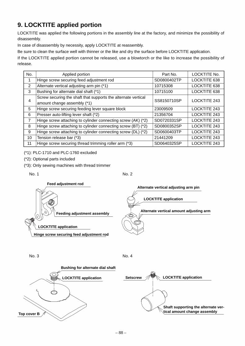
– 88 –
No. 1 No. 2
No. 3 No. 4
9. LOCKTITE applied portionLOCKTITE was applied the following portions in the assembly line at the factory, and minimize the possibility ofdisassembly.
In case of disassembly by necessity, apply LOCKTITE at reassembly.
Be sure to clean the surface well with thinner or the like and dry the surface before LOCKTITE application.
If the LOCKTITE applied portion cannot be released, use a blowtorch or the like to increase the possibility ofrelease.
No. Applied portion Part No. LOCKTITE No.1 Hinge screw securing feed adjustment rod SD0800402TP LOCKTITE 6382 Alternate vertical adjusting arm pin (*1) 10715308 LOCKTITE 6383 Bushing for alternate dial shaft (*1) 10715100 LOCKTITE 638
Screw securing the shaft that supports the alternate verticalamount change assembly (*1)
5 Hinge screw securing feeding lever square block 23009509 LOCKTITE 2436 Presser auto-lifting lever shaft (*2) 21356704 LOCKTITE 2437 Hinge screw attaching to cylinder connecting screw (AK) (*2) SD0720331SP LOCKTITE 2438 Hinge screw attaching to cylinder connecting screw (BT) (*2) SD0800352SP LOCKTITE 2439 Hinge screw attaching to cylinder connecting screw (DL) (*2) SD0600403TP LOCKTITE 24310 Tension release bar (*3) 21441209 LOCKTITE 24311 Hinge screw securing thread trimming roller arm (*3) SD0640325SP LOCKTITE 243
(*1): PLC-1710 and PLC-1760 excluded
(*2): Optional parts included
(*3): Only sewing machines with thread trimmer
Feed adjustment rod
Feeding adjustment assembly
LOCKTITE application
Hinge screw securing feed adjustment rod
Alternate vertical adjusting arm pin
LOCKTITE application
Alternate vertical amount adjusting arm
Bushing for alternate dial shaft
LOCKTITE application
Top cover B
Setscrew LOCKTITE application
Shaft supporting the alternate ver-tical amount change assembly
4 SS8150710SP LOCKTITE 243

– 89 –
No. 5 No. 6
No. 7 No. 8
No. 9 No. 10
No. 11
Feeding lever shaft
LOCKTITE application
Feeding lever
LOCKTITE application
Presser auto-lifting lever shaft
Cylinder connecting screw
LOCKTITE application
Hinge screw attaching tocylinder connecting screw
Cylinder connecting screw
LOCKTITE application
Hinge screw attaching to cylinderconnecting screw
Cylinder connecting screw
LOCKTITE application
Hinge screw attaching tocylinder connecting screw
Tension release bar
LOCKTITE application
Coupling attaching to tensionrelease bar
Coupling nut attaching to tension release bar
LOCKTITE application
Tread trimming roller arm
Connecting link
Hinge screw securing thread trimming roller arm

– 90 –
PLC-1710
PLC-1710-7
Location Throat plate Presser foot
Appearance
Part No. 40038970 40038969 40017286 40038972 40038976
PLC-1710
PLC-1710-7
Feed dog Feeding foot
Standard For thick thread Standard For thick thread With slit
Appearance
Part No. 40038971 40040294 21444559 40040295 23032055
10. Consumable part list/replaceable gauge part list(1) Consumable part lists
o PLC-1710, 1760
Consumable part Part No. Remarks
Needle MC321001400 Schmetz 134-35 Nm140
Hook (assembly) 40039010
Bobbin 10759603 Aluminum bobbin (with a knurling tool)
o PLC-1710-7, 1760-7
Consumable part Part No. Remarks
Needle MC321001400 Schmetz 134-35 Nm140
Hook (assembly) 40038731
Bobbin 10759603 Aluminum bobbin (with a knurling tool)
Moving knife 40038746
Counter knife 40038747
Clamp spring 40039404
o PLC-1760L
Consumable part Part No. Remarks
Needle MC321002000 Schmetz 134-35 Nm200
Hook (assembly) 40038870
Bobbin 10759603 Aluminum bobbin (with a knurling tool)
(2) Replaceable gauge part lists
o PLC-1710, 1710-7
Throat plateholder A
Throat plateholder B
ø2.3 ø3ø2.4 2.4
3.8
Location
ø2.3

– 91 –
PLC-1760
PLC-1760-7
PLC-1760L
Feed dog
Slot Circular hole For L
Appearance
6mm 40038800 40038810 40039009 40038783 —
8mm 40038797 40038808 40039008 40038782 —
10mm 40038795 40038806 40039007 40038781 40038897
12mm 40038792 40038802 40039006 40038780 —
o PLC-1760, 1760-7, 1760L
PLC-1760
PLC-1760-7
PLC-1760L
Throat plate Throat plate for lower tape
Standard For thread trimming For L Standard For thread trimming
Appearance
6mm 40038996 40038759 — 40039004 40038769 40038790
8mm 40038995 40038758 — 40039001 40038767 40038788
10mm 40038994 40038757 40038893 40038999 40038765 40038786
12mm 40038993 40038756 — 40038997 40038762 40038784
LocationThroat plate
holder
Par
t No.
Nee
dle
gaug
e
PLC-1760
PLC-1760-7
PLC-1760L
Feeding foot Feeding foot for guiding
Standard For L With slit Standard For L
Appearance
6mm 40038846 — 10783157 40038854 — 40038778
8mm 40038844 — 10783256 40038852 — 40038776
10mm 40038842 40038898 10783355 40038850 40039271 40038774
12mm 40038840 — 10783454 40038848 — 40038772
Location
Presser footwith guide
Par
t No.
Presser foot
Location
Par
t No.
Needleclamp
* Only [10mm] of needle gauge is available for PLC-1760L.
ø2.1 ø3 ø2.1 ø3
2.4
3.8
ø2.4 3.5
5.5
Nee
dle
gaug
eN
eedl
e ga
uge
ø2.1
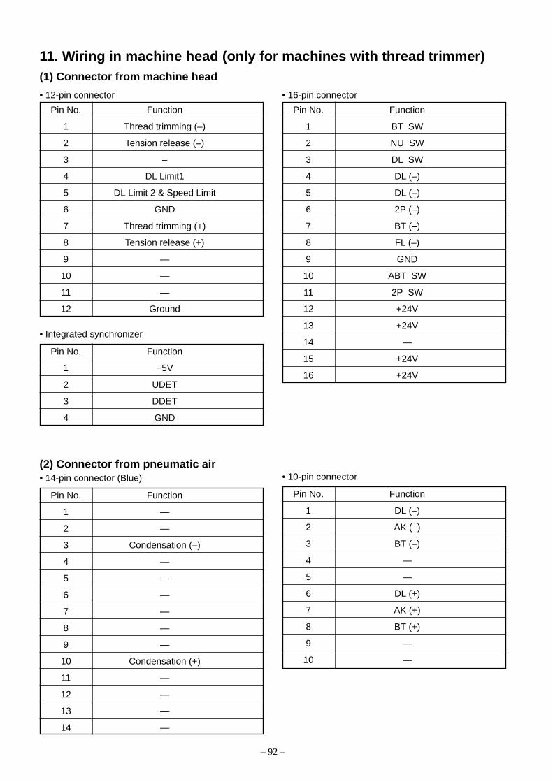
– 92 –
11. Wiring in machine head (only for machines with thread trimmer)(1) Connector from machine head
Pin No. Function
1 Thread trimming (–)
2 Tension release (–)
3 –
4 DL Limit1
5 DL Limit 2 & Speed Limit
6 GND
7 Thread trimming (+)
8 Tension release (+)
9 —
10 —
11 —
12 Ground
• 12-pin connector
Pin No. Function
1 BT SW
2 NU SW
3 DL SW
4 DL (–)
5 DL (–)
6 2P (–)
7 BT (–)
8 FL (–)
9 GND
10 ABT SW
11 2P SW
12 +24V
13 +24V
14 —
15 +24V
16 +24V
• 16-pin connector
Pin No. Function
1 +5V
2 UDET
3 DDET
4 GND
• Integrated synchronizer
Pin No. Function
1 —
2 —
3 Condensation (–)
4 —
5 —
6 —
7 —
8 —
9 —
10 Condensation (+)
11 —
12 —
13 —
14 —
• 14-pin connector (Blue)(2) Connector from pneumatic air
Pin No. Function
1 DL (–)
2 AK (–)
3 BT (–)
4 —
5 —
6 DL (+)
7 AK (+)
8 BT (+)
9 —
10 —
• 10-pin connector

– 93 –
Function
CN50-1 CN50-2 CN50-3 CN50-4
1 +24V +24V +24V +24V
2 FL (–) DL (–) Condensation (–)
3 BT (–) 2P (–) Short tail (–) —
4 GND GND GND GND
• Connector CN50-1 to 4
(3) Connector from relay cable
Pin No.
Function
CN51-1 CN51-2 CN51-3 CN51-4
1 +12V +12V +12V +12V
2 NU SW DL SW Sewing machine stop signal DL Limit 1
3 ABT SW 2P SW Thread rack switch DL Limit 2 & Speed Limit
4 GND GND GND GND
• Connector CN51-1 to 4
Pin No.
Pin No. Function
1 Thread trimming (–)
2 —
3 —
4 —
5 BT SW
6 —
7 Tension release (–)
8 Thread trimming (+)
9 —
10 Ground
11 —
12 GND
13 —
14 Tension release (+)
• 4-pin connector (Blue)
Signal indicating sewingmachine is in operation
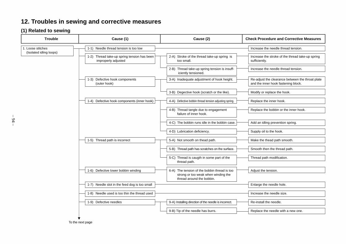
– 94 –
1. Loose stitches 1-1) Needle thread tension is too low Increase the needle thread tension. (Isolated idling loops)
1-2) Thread take-up spring tension has been 2-A) Stroke of the thread take-up spring is Increase the stroke of the thread take-up spring improperly adjusted too small. sufficiently.
2-B) Thread take-up spring tension is insuff- Increase the needle thread tension. iciently tensioned.
1-3) Defective hook components 3-A) Inadequate adjustment of hook height. Re-adjust the clearance between the throat plate(outer hook) and the inner hook fastening block.
3-B) Degective hook (scratch or the like). Modify or replace the hook.
1-4) Defective hook components (inner hook) 4-A) Defective bobbin thread tension adjusting spring. Replace the inner hook.
4-B) Thread tangle due to engagement Replace the bobbin or the inner hook.failure of inner hook.
4-C) The bobbin runs idle in the bobbin case. Add an idling prevention spring.
4-D) Lubrication deficiency. Supply oil to the hook.
1-5) Thread path is incorrect 5-A) Not smooth on thead path. Make the thead path smooth.
5-B) Thread path has scratches on the surface. Smooth then the thread path.
5-C) Thread is caugth in some part of the Thread path modification.thread path.
1-6) Defective lower bobbin winding 6-A) The tension of the bobbin thread is too Adjust the tension.strong or too weak when winding thethread around the bobbin.
1-7) Needle slot in the feed dog is too small Enlarge the needle hole.
1-8) Needle used is too thin the thread used Increase the needle size.
1-9) Defective needles 9-A) Installing direction of the needle is incorrect. Re-install the needle.
9-B) Tip of the needle has burrs. Replace the needle with a new one.
Trouble Cause (1) Cause (2) Check Procedure and Corrective Measures
12. Troubles in sewing and corrective measures(1) Related to sewing
To the next page

– 95 –
1-10) Defective feed timing 10-A) Feed timing is earlier than the standard one. Re-adjust the feed timing. .
10-B) Height of the feed dog differs from the Re-adjust the height of the feed dog.standard value.
1-11) Defective hook timing 11-A) Hook timing is too early. Re-adjust the hook timing.
1-12) Defective needle entry Align the needle hole center of the needle dogwith the needle center.
1-13) Inner hook opening lever is defective 13-A) The clearance between the inner hook Re-adjust the inner hook guide.and the inner hook guide is too muchor eliminated.
1-14)Needle thread tangle with feed dog 13-A) Stroke of the thread take-up spring is too short. Increase the stroke.
2. Loose stitches 2-1) The needle thread is pulled up completely. Use the feeding foot with the slit. (needle thread floating)
(Refer to "10.-(2) Replaceable gauge part lists".)
3. Stitch Skipping 3-1) Defective needle 1-A) The needle is installed facing in the Reset the needle.wrong direction.
1-B) Bent needle Replace the needle with a new one.
1-C) Tip of the needle is blunt. Replace the needle with a new one.
1-D) The needle is too thick or too thin for the Replace the needle with a new one.thread used.
3-2) Defective hook components 2-A) Blade point of the hook is blunt or worn out. Correct the blade point of the hook or replacethe hook with a new one.
2-B) Incorrect hook timing Re-adjust the hook timing.
2-C) Height of the needle bar is not correct. Re-adjust the vertical position of the needle bar inthe light of the blade point of the hook.
2-D) Clearance between the blade point of Minimize the clearance.the hook and the needle is not correct.
2-E) Effective amount of the needle guard is wrong. Adjust the effective amount of the needle guard.
2-F) Thread loops are not made with consistency. Wind the thread around the needle.
3-3) The needle thread tension is too high Decrease the needle tension.
Trouble Cause (1) Cause (2) Check Procedure and Corrective Measures
Continued from the previous page
To the next page

– 96 –
3-4) Sewing speed is too high Decrease the sewing speed.
3-5) Height of the needle bar is not correct 5-A) Height of the needle bar is not adjusted Re-adjust the height of the needle bar.to the specified dimension.
3-6) Defective upper feeding foot 6-A) The needle hole of the upper feeding Reset the upper feeding foot.foot and needle are in contact.
3-7) Improper feed timing Re-adjust the feed timing.
3-8) Thread take-up spring has been improperly 8-A) Stroke of the thread take-up spring is Decrease the tension of the spring.adjusted too high.
8-B) The thread take-up spring is too tense. Decrease the tension of the spring.
3-9) Incorrect needle entry 9-A) The needle comes in contact with the Adjust the needle entry.needle hole in the throat plate.
3-10) Improper pressure of the presser foot 10-A) Pressure of the presser foot is too low. Increase the pressure of the presser foot.
10-B)The work clamp foot is floating. Re-adjust the lifting amount of the work clamp foot.
4. Needle Thread Breakage 4-1) Thread path is incorrect 1-A) Thread path is not smooth on the surface. Make the thead path smooth. (Cutting) (Hangnail) 1-B) Thread path has scratches on the surface. Smoothen the thread path.
1-C) Thread is caught in some part of the thread path. Thread path modification.
4-2) Improper needle thread tension Adjust the needle thread tension.
2-A) The tension controlled by the tension Adjust the tension controller No. 1 thread tensioncontroller No. 1 is too low. to prevent the thread from flapping.
4-3 Defective needle 3-A) The needle is installed facing the wrong Re-install the needle in the correct manner.direction.
3-B) Needle abnormality Replace the needle with a new one.(Deformation, breakage, wear)
3-C) The needle is too thick or too thin for the Replace the needle with a new one.thread used.
Trouble Cause (1) Cause (2) Check Procedure and Corrective Measures
Continued from the previous page
To the next page
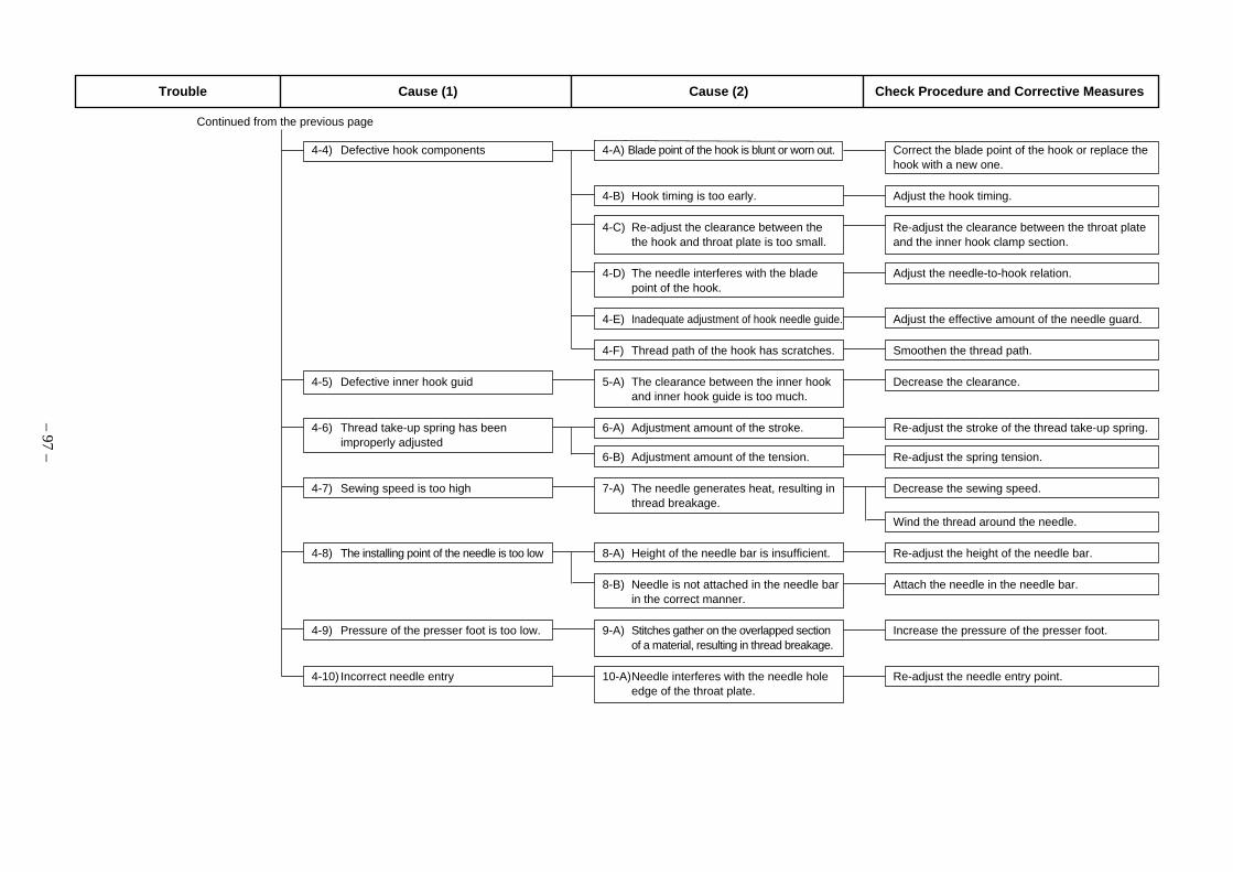
– 97 –
4-4) Defective hook components 4-A) Blade point of the hook is blunt or worn out. Correct the blade point of the hook or replace thehook with a new one.
4-B) Hook timing is too early. Adjust the hook timing.
4-C) Re-adjust the clearance between the Re-adjust the clearance between the throat platethe hook and throat plate is too small. and the inner hook clamp section.
4-D) The needle interferes with the blade Adjust the needle-to-hook relation.point of the hook.
4-E) Inadequate adjustment of hook needle guide. Adjust the effective amount of the needle guard.
4-F) Thread path of the hook has scratches. Smoothen the thread path.
4-5) Defective inner hook guid 5-A) The clearance between the inner hook Decrease the clearance.and inner hook guide is too much.
4-6) Thread take-up spring has been 6-A) Adjustment amount of the stroke. Re-adjust the stroke of the thread take-up spring.improperly adjusted
6-B) Adjustment amount of the tension. Re-adjust the spring tension.
4-7) Sewing speed is too high 7-A) The needle generates heat, resulting in Decrease the sewing speed.thread breakage.
Wind the thread around the needle.
4-8) The installing point of the needle is too low 8-A) Height of the needle bar is insufficient. Re-adjust the height of the needle bar.
8-B) Needle is not attached in the needle bar Attach the needle in the needle bar.in the correct manner.
4-9) Pressure of the presser foot is too low. 9-A) Stitches gather on the overlapped section Increase the pressure of the presser foot.of a material, resulting in thread breakage.
4-10) Incorrect needle entry 10-A)Needle interferes with the needle hole Re-adjust the needle entry point.edge of the throat plate.
Trouble Cause (1) Cause (2) Check Procedure and Corrective Measures
Continued from the previous page

– 98 –
5. Irregular Stitches 5-1) Defective hook components 1-A) Oil in the hook is insufficient. Lubricate the hook race.
1-B) Defective hook (scratch, dust). Clean, modify, or replace the hook.
1-C) The clearance between the needle and Increase the clearance.throat plate is too small.
1-D) The inner hook opening lever provides Decrease the clearance at the inner hook openingexcessive clearance. lever.
1-E) Hook timing is too early. Retard hook timing.
5-2) Defective bobbin and/or inner hook 2-A) Defective bobbin thread tension Replace the inner hook with a new one. adjusting spring.
2-B) The bobbin is not engaged with the inner Replace the bobbin or inner hook with a new one.hook. As a result, the bobbin thread cannotbe led smoothly.
2-C) Bobbin runs idle in the inner hook. Increase the idling prevention spring pressure.
2-D) Bobbin thread is not wound. As a result, Adjust the tension of the bobbin winder or thethe bobbin thread fails to be fed smoothly. position of the bobbin winder tension controller.
2-D)Thread has been wound excessively on Re-wind the bobbin thread to the extent where thethe bobbin. thread wound round the bobbin does not protrude
from the periphery of the bobbin.
5-3) The needle thread tension and the bobbin Increase the thread tension.thread tension are too low.
5-4) Thread take-up spring has not been 4-A) Adjustment amount of the stroke. Re-adjust the stroke of the thread take-up spring.correctly adjusted
4-B) Adjustment amount of the tension. Re-adjust the tension of the thread take-up spring.
5-5) Improper thread path 5-A) Thread path is not smooth on the surface. Make the thead path smooth.
5-B) Thread path has scratches on the surface. Smoothen the thread path.
5-C) Thread is caught in some part of the thread path. Thread path modification.
5-6) Defective feed timing Re-adjust the feed timing.
Trouble Cause (1) Cause (2) Check Procedure and Corrective Measures

– 99 –
1. Stitch skipping at the start of 1-1) Length of thread left at the needle tip 1-A) Abnormality in needle thread route. Run the thread in the correct route to avoid sewing after thread trimming is too short. abnormal tension on the needle thread.
1-B) Tension of the tension disk No. 1 is too Decrease the needle tension.high.
1-C) The tension disk fails to release the thread Float the disk with the thread release solenoid.sufficiently at the time of thread trimming.
1-D) Timing of thread trimming is too early. Adjust the thread trimming cam.
1-E) Moving knife and/or the hook has Perform modification or replacement.scratches.
1-F) Deviation of work clamp foot from cloth Trim the thread above cloth.at thread trimming.
1-2) The bobbin thread is not held after 2-A) The installing position of the clamp Re-adjust the position. thread trimming. spring is not correct.
2-B) Clamp spring pressure is too low. Re-adjust the spring tension.
2-C) Deformed clamp spring. Replace the clamp spring with a new one.
1-3) Needle is too thick. Replace the needle with a thinner needle.
1-4) Pressure of the presser foot is too low. Increase the pressure of the presser.
1-5) The needle thead is too thin. Do not run the needle thread under the presser ofthe thread guide in front of the needle bar guide.
2. Thread cast-off from the needle 2-1) Nonsmooth thread is used. Change the route of the needle thread to decrease immediately after thread trimming. the thread bent points.
2-2) Adjustment amount of thread take-up 2-A) The tension is too weak because the Shorten the stroke to make the tension stronger.spring. stroke is too long.
Trouble Cause (1) Cause (2) Check Procedure and Corrective Measures
(2) Thread trimming and concerns

– 100 –
3. The thread trimmer fails to cut the 3-1) Moving knife 1-A) Defective shape Replace the moving knife and the counter knife threads. with new ones.
1-B) Defective adjustment amount of position. Adjust the position of the moving knife.
3-2) The moving knife fails to operate 2-A) Defective synchronizer timing. Re-adjust the synchronizer timing.
2-B) Defective thread trimming timing. Re-adjust the thread trimming cam.
2-C) Thread trimming solenoid failure Replace the thread trimming solenoid.
3-3) The moving knife stops during thread 3-A) Thread used is too thick. Use a specified thread.trimming
3-B) Defective thread trimming timing. Re-adjust the timing for the thread trimming cam.
3-C) Needle thread tension is too high. Adjust the tension of the needle thread.
Decrease the thread tension controlled by thetension controller No. 1.
3-D) The bobbin thread tension is too high. Adjust the tension of the bobbin thread.
3-E) The counter knife pressure is too strong. Re-adjust the knife pressure.
3-4) Counter knife 4-A) Defective shape. Replace the counter knife with new ones.
4-B) Defective adjustment amount. Adjust the counter knife position and the knife pressure.
3-5) Condensation system 5-A) Pneumatic system Perform wiring properly.
The air pressure is too low.Adjust the air pressure between 0.45 and 0.5 MPa.
5-B) Cylinder failure Replace the cylinder.
3-6) Deviation of work clamp foot from cloth 6-A) The moving knife cannot hold the thread Trim the thread above cloth.at thread trimming securely due to thread bending.
Trim the thread while pulling the work in the feedingdirection.
3-7) The thread trimmer fails to catch the 7-A) Breakage of moving knife tip Replace the moving knife with anew one.needle thread.
7-B) Stitch skipping at the final stitch Re-adjust the timing for the needle and hook.
7-C) Defective thread trimming timing Re-adjust the thread trimming cam.
Trouble Cause (1) Cause (2) Check Procedure and Corrective Measures
To the next page

– 101 –
3-8) The thread trimmer rails to catch the 8-A) Defective adjustment amount of moving Re-adjust the hight.bobbin thread. knife
Re-adjust the initial position.
8-B) Breakage of moving knife tip Replace the moving knife with a new one.
8-C) Wrong bobbin thread path Run the bobbin thread in the correct route.
8-D) Thread trimming after thread falling Trim the thread while pulling the work in the feedingdirection.
4. Single yarn residue at thread 4-1) Moving knife 1-A) Knife wear/breakage Replace the moving knife with a new ones. trimming
4-2) Counter knife 2-A) Knife wear/breakage Replace the counter knife with new ones.
2-B) Too weak knife pressure Re-adjust the knife pressure.
4-3) Misalignment between moving knife Adjust the positions of the moving knife and counterand counter knife knife.
4-4) Defective thread trimming timing 4-A) Too late timing Re-adjust the timing.
4-5) Deviation of work clamp foot from cloth 5-A) The moving knife cannot hold the thread Trim the thread above cloth.at thread trimming securely due to thread bending.
Trim the thread while pulling the work in thefeeding direction.
Trouble Cause (1) Cause (2) Check Procedure and Corrective Measures
Continued from the previous page

– 102 –
Alternate vertical amount (mm)
13. List of the sewing speeds
o PLC-1710, 1760
1 2
2
4
6
9
3 4 5 66.5
MAX. 1,800rpm
MAX.2,500rpm
MAX.1,600rpm
o PLC-1710-7, 1760-7
1 2
2
4
6
9
3 4 5 66.54.752.5
MAX. 1,800rpm
MAX.2,500rpm
MAX.2,200rpm
MAX.1,600rpm
o PLC-1760L
1
2
4
6
9
12
32 4 5 66.54.75
MAX. 1,800rpm
MAX. 1,600rpm
Pitch(mm)
Pitch(mm)
Pitch(mm)
Alternate vertical amount (mm)
Alternate vertical amount (mm)

14. Table drawing(1) Flat table
Part No. : 40038940
ø10 through hole(The sruface C2 chamfering)
The surfaceC1.5 chamfering
– 103 –
Drawer stopper installingposition (On the botton surface)
4-ø3.5 on the bottom surface,depth 20
8 x ø3.4 depth 10
ø18 throughhole
ø24 depth 35(C2 chamfering)
2-ø3.4 on the bottomsurface, depth 10
2 x ø3.4 depth 10
2 x ø3.4 depth 10
ø13 throughhole
3 x 8 drilling

MEMO

®
MARKETING & SALES H.Q.8-2-1, KOKURYO-CHO,CHOFU-SHI, TOKYO 182-8655, JAPANPHONE : (81)3-3480-2357 • 2358FAX : (81)3-3430-4909 • 4914
Copyright © 2006 JUKI CORPORATION.
All rights reserved throughout the world.
Please do not hesitate to contact our distributors or agents in your area for further information when necessary.* The description covered in this engineer's manual is subject to change for improvement of the
commodity without notice.06 · 08 Printed in Japan (E)
This manual uses environment-friendly soyink.
The environmental management system to promote and conduct1the technological and technical research, the development and
design of the products in which the environmental impact is consid-ered,
2the conservation of the energy and resources, and the recycling, inthe research, development, design, distribution, sale and mainte-nance service of the industrial sewing machines, household sew-ing machines and industrial-use robots, etc. and in the sale andmaintenance service of data entry system and in the purchase, dis-tribution and sale of the household commodities including thehealthcare products.