plastic blow molding
TRANSCRIPT

The Magazine for ENERGY EFFICIENCY in Compressed Air, Pneumatics, Blower and Vacuum Systems
airbestpractices.com
Plastic Blow Molding
Mar
ch 2
012
10 The NPE 2012 Plastics Show Preview
16 Plastic Injection Molder Saves $53,000
22 Plastic Processor Outsources Compressed Air as the 4th Utility
26 Six Applications for Compressed Air Storage
39 International Wire Trims Compressed Air Costs
34 PN
EUMAT
IC AND VA
CUUM EN
ERGY
OPTIM
IZATIO
N ON O
EM M
ACHIN
ES
PNEU
MATIC
AND VACU
UM ENER
GY
OPTIM
IZATIO
N ON O
EM M
ACHIN
ES
kW
CO2

Put a lid on energy waste
© Copyright 2011 Atlas Copco Compressors LLC. All rights reserved.
Hi, I'm Bob, Senior Marketing Support Specialist at Atlas Copco Compressors. For the last 38 years, I've beenpart of the team taking care of our valued customers in the United States. Today, let me tell you how VariableSpeed Drive technology represents a great value proposition for your production.
All across the globe, customers are compressing air that just goes to waste. Energy can represent over 80%of a compressor’s lifecycle cost and generating compressed air can account for more than 40% of a plant’stotal electricity bill. Most production environments have a fluctuating air demand depending on the time ofday, week or even month. So put a lid on those energy costs with Atlas Copco’s VSD technology that mirrorsair usage, automatically adjusting the motor speed depending on the demand, making major energy costssavings a reality while helping to protect the environment for future generations.
Our mission is to continue to bring sustainable productivity through safer, cleaner, more energy-efficient, andcost-effective compressed air technology. Simply log onto www.atlascopco.us/bobusa or call 866-688-9611to learn more about us, our products, and how we have earned and will continue to earn our reputation.
Atlas VSD Ad 8.375 x 10.875:Layout 2 6/22/11 11:01 AM Page 1

Hitachi SRL Series Oil-Free Air CompressorsInnovation • 100% Oil-Less Design • Superior Sound Quality
SRL Series Multiplex (Multiple Motor/Multiple
Scroll Configuration)
SRL Series Simplex (Single Motor/Single Scroll Configuration)
SRL Series Features• Patented Labyrinth Lap for
extended life and reliability
• World’s Largest Unitary Scroll (7.5HP)
• Microprocessor standard with Control Cycle Logic for compressor longevity
• Multi-stage cooling for stable discharge temperatures
• Highest Air Purity
• Environmentally Friendly
• Low cost of operation
• Ultra low sound with standard quiet enclosure
• Space Saving Footprint
• Product Range 1.5kW — 5.5kW Simplex Units 7.5kW — 16.5kW Multiplex Units
• Pressure applications up to 145 PSI
• Energy Saving Variable Drive Mode (Multiplex Only)
Hitachi’s history of success and proven experience in scroll technologies has enabled Worldwide Innovation of producing
the World’s First Scroll for air compression. With over 20+ years experience in scroll compression, the SRL Series of Oil Free
Compressors represents our alignment of value for the discriminating air user.
Scroll Configuration)Scroll Configuration)Scroll Configuration)
HITACHI AMERICA, LTD.Air Technology Group
5808-Q Long Creek Park Drive, Charlotte, NC 28269 Tel: 704.494.3008 x28 www.hitachi-america.us/airtech; [email protected]
Hitachi Industrial Equipment Systems Co., Ltd.
Interested to become an Authorized Distributor for Hitachi SRL Series Compressors? See our ad in the Job Market Section.
ATG Multiplex SRL Ad 8.375 x 10.875.indd 1 1/11/12 11:13 PM

S U S T A I N A B L E M A N U F A C T U R I N G F E A T U R E S
The NPE 2012 Plastics Show Preview | 10By Compressed Air Best Practices® Magazine
The System Assessment | 16Plastic Injection Molder Saves $53,000
By Hank van Ormer, Air Power USA
Plastics Processor Outsources | 22Compressed Air as the 4th Utility
By Tim Tensing, DirectAIR®
Six Applications for Compressed Air Storage | 26By Dean E. Smith, iZ Systems
The Demand-Side Technology Provider | 34Pneumatic and Vacuum Energy
Optimization On OEM MachinesBy Philip O’Neill, Bosch Rexroth
International Wire Trims Compressed Air | 39Costs Using the “Systems Approach”
By Tom Taranto and Ram Kondapi for the Compressed Air Challenge®
C O L U M N S From the Editor | 5 Compressed Air, Pneumatics, | 6
Vacuum & Blower Industry News
Resources for Energy Engineers | 46 Technology Picks
Advertiser Index | 48
The Job Market | 49
The Marketplace | 50
10
22
34
| 0 3 / 1 2
4 airbestpractices.com
COLUMNS

FROM THE EDITORFROM THE EDITORFROM THE EDITORFROM THE EDITORFROM THE EDITORFROM THE EDITORThe Plastics Industry at 100 psi
The plastics industry is the third largest manufacturing segment in North America. The U.S. plastics industry employs 1.1 million workers in the U.S. and provides nearly $379 billion in annual shipments. Past issues have talked about the PET blow molding industry that uses 580 psi compressed air for bottle blowing. This issue focuses on the larger plastics industry segment, using 100 psi compressed air, engaged in injection and extrusion blow molding. There are over 1,100 plastics manufacturing firms in California alone. Average installed air compressor horsepower is 400–800 hp.
Over 45,000 visitors will have the opportunity to learn more about the compressed air, pneumatic, blower and vacuum systems required to run their blow molding operations at the triennial NPE 2012 international plastics exposition. Our “2012 NPE Show Preview” has an overview of the firms exhibiting.
Veteran system assessment expert, Hank van Ormer, provides us with a case study on how his firm helped a plastic injection molder reduce their annual energy costs by $53,000 — a reduction of over 50%. The plant operated 450 horsepower of air compressors at 105 psig. The system assessment found ways to reduce compressed air demand and then automated the air compressors to run in a more efficient manner. The costs to implement were so insignificant that the ROI was 30 days.
Many of these plastics blow molding plants (again at 100 psi) have a dense-phase transport system creating significant compressed air flow spikes. Tim Tensing, from DirectAIR, provides us with an interesting article on how his firm helped a plastic processor address these spikes and reduce their compressed air annual energy costs from $276,000 to $111,000. Interestingly, the firm also decided to outsource compressed air, as the 4th Utility, and realize further benefits.
Veteran plastics industry system assessment expert, Dean Smith, provides us with a very organized and detailed article on “The Six Applications for Compressed Air Storage”. The significant benefits include increased production output and reduced energy consumption from the air compressors.
“Pneumatic and Vacuum Energy Optimization On OEM Machines”, is an article provided to us by Philip O’Neil from Bosch Rexroth. This topic represents the next frontier in system assessments. End users are beginning to realize that they must ask their OEM suppliers to provide energy-optimized equipment.
Tom Taranto and Ram Kondapi, on behalf of the Compressed Air Challenge®, finish off the edition with an excellent system assessment case study titled, “International Wire Trims Compressed Air Costs Using the Systems Approach”.
Our mission is to distribute educational and motivational content on the positive work being done every day by people, like you, who get their hands dirty and get the job done with profitable energy efficiency projects. We thank the authors above for sharing their knowledge and thank you for your support and for investing in Compressed Air Best Practices®.
ROD SMITHEditorTel: [email protected]
COMPRESSED AIR BEST PRACTICES® EDITORIAL ADVISORY BOARD
Indus
trial
Ener
gy M
anag
ers
Thomas MortGlobal Program Manager, Energy Efficiency
Archer Daniels Midlands
Richard Feustel Corporate Energy Services Manager Briggs & Stratton
Brad Runda Manager, Energy Saint Gobain
Eric Battino Supplier Sustainability Manager PepsiCo
Doug Barndt Manager, Demand Side Energy-Sustainability Ball Corporation
Jennifer MeierGlobal Environmental, Energy & Plant Engineering Manager
Visteon
Mike Seiter Maintenance Staff, Reliability Group
Honda of America
William Jerald Energy Manager CalPortland
Tech
nolog
y/Sy
stem
Ass
essm
ents
Nate AltfeatherEngineering Manager, Focus on Energy Programs
SAIC Wisconsin
Ron Marshall Customer Engineering Services
Compressed Air Challenge®
Bill Scales CEO Scales Industrial Technologies
Ted Clayton Energy and Power Management Services
KAMAN Industrial Technologies
Paul Humphreys
Vice President Communications Atlas Copco
Wayne Perry Technical Director Kaeser Compressors
David Brittain Director of Engineering & Marketing Becker Pumps
Jay Francis Vice President Marketing
SPX Flow Technology
Jon Jensen Energy Conservation Manager
SMC Corp. of America
Hank Van Ormer President Air Power USA
Les Ottinger President/CEO THP Inc.
Nitin Shanbhag Senior Manager, Industrial Division Hitachi America
Mike Gembala Vice President Blake & Pendleton, Inc.
Pierre Noack President Aerzen USA
®
airbestpractices.com0 3 / 1 2 |
5 airbestpractices.com
COLUMNS

C O M P R E S S E D A I R , P N E U M A T I C S , C O M P R E S S E D A I R , P N E U M A T I C S , C O M P R E S S E D A I R , P N E U M A T I C S , C O M P R E S S E D A I R , P N E U M A T I C S , C O M P R E S S E D A I R , P N E U M A T I C S , C O M P R E S S E D A I R , P N E U M A T I C S , V A C U U M & B L O W E R I N D U S T R Y N E W S V A C U U M & B L O W E R I N D U S T R Y N E W S V A C U U M & B L O W E R I N D U S T R Y N E W S V A C U U M & B L O W E R I N D U S T R Y N E W S V A C U U M & B L O W E R I N D U S T R Y N E W S V A C U U M & B L O W E R I N D U S T R Y N E W S
Mattei Compressors introduced a Gas
Compressor line of products. Jay R. Hedges,
General Manager of Mattei Compressor, North
America, announced that Mattei has developed
a full line of Rotary Vane Gas Ends and Gas
Compressor packages for the North American
Market. Part of a global strategy to move
aggressively into the natural gas, landfill gas and
micro turbine markets, Mattei North America
now offers a full line of Gas Ends ranging from
5.5 hp (23 cfm) to 75 hp (313 cfm).
“We see Natural Gas and Landfill Gas
compression as growing markets as the
U.S. These are market driven steps toward
American energy independence through
traditional and non-traditional fuels” Hedges
said. “The U.S. has an abundance of untapped
Natural Gas reserves that are slowly becoming
economically competitive as oil prices remain
high. Methane gases produced by landfills
and sewage treatment facilities are technically
and financially viable after decades of
experimentation, and new EPA regulations.
The Mattei Rotary Vane Technology is well
suited for gas applications due to its energy
efficiency running at slow speeds ranging from
1200 rpm to 1800 rpm at 60 Hz, compared
to pistons and rotary vane compressors
typically running from 3500 to 7500 rpm.
Running at slower speeds increases the life of
compressors makes the compression process
more efficient, reduces wear on moving parts,
and reduces service costs. With no bearings to
wear or decrease efficiency over time, Mattei
Rotary Vane compressors boast a design life
of 100,000 hours.
“Our Italian affiliate, Mattei SPA has designed
and built complex engineered packages for
gas applications such as compressing landfill
gas to drive large Micro turbines. Building on
this experience, our North American strategy
will be to supply standard gas ends from
5.5 hp (23 cfm) to 75 hp (313 cfm). We
will work with a network of Gas Packagers
in North America to engineer and assemble
gas packages for complex projects in our
markets”, according to Hedges.
“The entry into Gas Compression is a strategic
decision as we position Mattei’s Rotary Vane
Technology, to expand into new applications
and new markets where we have competitive
advantages” added Guilio Contaldi, CEO
of Mattei SPA based in Milan, Italy. “As the
world’s largest Rotary Vane compressor
manufacturer, we have taken the time to study
market demand and to develop a product line
of high quality gas compressors that will meet
the needs of a major part of the market from
4 kW to 55 kW. Moving into Gas Compression
offers an opportunity for growth globally,
but particularly in the U.S. where Mattei
Compressor sales have doubled in the past
4 years.” www.matteicomp.com
Atlas Copco has been ranked the world’s
tenth most sustainable company in the annual
Global 100 list, presented today at the World
Economic Forum in Davos, Switzerland.
Atlas Copco is the highest ranked industrial
company. “Our work to develop Atlas Copco
in a sustainable and profitable way is yielding
results,” said Annika Berglund, Senior Vice
President Corporate Communications at Atlas
Copco. “This long-standing effort was further
enhanced last year with the introduction of a
range of new goals. We are proud to see this
development recognized on the Global 100
list.” The Global 100 list is presented annually
at the World Economic Forum. It is based on
a selection of 4 000 developed and emerging
market companies, which are measured
against key performance indicators such as
revenues in relation to consumption of energy
and water. Atlas Copco was included on the list
for five consecutive years until 2010, but was
not ranked in 2011. http://global100.org
Festo Corporation introduced
Festo Energy Saving Services. Pneumatic
installations frequently do not include any
monitoring facilities. More and more industrial
companies are using precise compressed air
consumption data as the main criterion for
the choice of new equipment. With a detailed
compressed air consumption analysis, they
can make savings of up to 50% more than
with conventional methods. Even before
commissioning, a compressed air consumption
analysis can determine the precise compressed
air consumption of an installation — both
during normal operation and with machines
®
airbestpractices.com | 0 3 / 1 2
6 airbestpractices.com
COLUMNS

Where Ideas Meet Industry
Since1948, SPX has set the global standard for energy efficient compressed air treatment
solutions. The tradition continues with the introduction of the HES Series high capacity
refrigerated air dryer, flows 3750 to 12500 scfm (6371-21238 nm3/h).
the InnovatIon edge
Utilizing the latest technological advancements, the HES Series offers a new way of thinking
and fresh approach to efficiently treat compressed air.
724.745.1555
Looking For A new wAy to eFFicientLy treAt compressed Air?
Featuring:
• Power consumption in direct proportion to real-time demand. • Redundancy in critical components offering fault- tolerant operation. • Modular construction promotes ease of movement and installation versatility.• ISO Quality Class performance for particulate removal, pressure dew point & remaining oil.
www.spx.com
at a standstill. It thus guarantees optimum
dimensioning of the compressed air supply
system and prevents unnecessary costs, which
might be caused by an overdimensioned
compressed air distribution system.
When an installation is optimized with Energy
Saving Services, the aim is to avoid damage
and breakdowns in advance. Festo offers
various condition monitoring and diagnostic
measures for this purpose. Through the
continuous monitoring of critical components,
it is possible to detect wear, pressure, and
flow changes at an early stage and avoid the
danger of machine downtime. If a breakdown
nonetheless occurs, the diagnostic systems
ensure that the cause of the trouble is
quickly located. Energy Monitoring GFDM
is a complete system for the continuous
monitoring of compressed air consumption
and volumetric flow. Alternatively, installation
operators can select a customer-specific
condition monitoring system. Diagnostic
systems are compiled from function modules
in accordance with individual customers’
requirements. The available functions include
not only consumption monitoring, but also
time monitoring of actuators and valves,
monitoring of vacuum applications, and
detailed monitoring of actuators (e.g.
force monitoring and fault detection).
www.festo.com/us.
Sullair Corporation announced today
that it will invest in its global headquarters
here, creating up to 113 new jobs by 2015.
Sullair expects to invest up to $12.7 million
to purchase new equipment and make energy
efficiency upgrades at its 410,000 square-foot
LaPorte County facility. “Sullair has called
Indiana home for decades and we are pleased
that they are continuing to invest in our state,”
said Governor Mitch Daniels. “By maintaining
one of the best business climates in the nation,
Indiana is able to attract and retain companies
like Sullair and we look forward to many more
years of success from this global leader.”
Established in 1965, Sullair is headquartered
in Michigan City with manufacturing facilities
in China, Australia and the United States.
The company has already begun hiring new
®
.com0 3 / 1 2 |
7 airbestpractices.com
COLUMNS

production associates. “We expect to see
increasing demand in our developed markets
as the worldwide economy shakes off the
lingering effects of the recent recession,” said
Henry Brooks, president of Sullair. “Investing
in our U.S. sites will help us meet that demand
while providing resources for technological
research.” www.sullair.com
UE Systems announced Ultrasound World
VIII set for May 14-17, 2012. Ultrasound
World, considered to be the major forum for
ultrasound technology will take place May 14
through 17, 2012 at the Clearwater Hilton in
Clearwater Beach Florida. Entering its eighth
year, it has grown to become recognized as
one of the top conferences for reliability and
energy conservation. The program will include
presentations and short courses by users of
the ultrasound technology and will cover a
wide range of topics for condition monitoring
and energy conservation. One presentation by
Todd Fraser of Procter and Gamble titled “No
More Equipment Failures! Can You Say That?”
will describe how his department dramatically
reduced bearing failure incidents using
ultrasound technology. Also of interest is a
short course: Clean, Green and Reliable, “How
equipment reliability delivers low cost, energy
efficient assets at plants around the world!”
Other important topics such as: detecting
and analyzing electrical fault conditions with
ultrasound, and effective energy conservation
practices will be included in the program.
www.uesystems.com
Chicago Pneumatic announced the
appointment of Todd Francis as the new
Vice President, North America for stationary
compressors. Francis will be based out of
Chicago Pneumatic’s Rock Hill, S.C., office,
and will be responsible for new business
development and further building Chicago
Pneumatic’s distributor network across the
North American compressor markets. “On
behalf of the entire Chicago Pneumatic team,
I am very excited to welcome Todd to his new
role as Vice President, North America,” said
Ellen Steck, President, Chicago Pneumatic.
“Todd’s extensive background with Chicago
Pneumatic Construction and the Atlas Copco
Group, combined with his experience leading
business development efforts across a variety
of construction and heavy equipment business
units, position him for immediate success
as our new Vice President, North America.”
Francis joins the Chicago Pneumatic
executive team after more than two decades
in the commercial construction and heavy
equipment sales and rental field, including
more than seven years as part of the Atlas
Copco group of companies. Francis previously
served as National Account Manager for
Chicago Pneumatic Construction, where
he was responsible for managing and
expanding national accounts, cross-selling
CP products while developing new business
opportunities. Prior, Francis served in senior
sales management positions with Allied
Construction/Sandvik Tamrock and The
Caterpillar Rental Store. www.cp.com
Spirax Sarco announced a plant expansion
in its’ Blythewood, South Carolina operation
to accommodate growth in its steam system
solutions business. The new facility has over
35,800 square feet of office and production
space. “Our business is continually growing
due to the hard work and dedication of our
employees. This facility will enable Spirax
Sarco to successfully meet the growing industry
demand for steam system solutions and to
better serve our customers nation-wide,”
said Stephen Gow, Director of Marketing.
www.spiraxsarco.com/us
Gardner Denver announced fourth
quarter results that established a quarterly
record for DEPS, and full year results that
established records for revenue, operating
income, operating margin, net income
and DEPS.
p Fourth quarter revenues of $614 million and orders of $598 million increased 16% and 14%, respectively, over the prior year
p Delivers record fourth quarter diluted earnings per share ("DEPS") of $1.52, including $0.02 of profit improvement costs and other items, resulting in Adjusted DEPS of $1.54, up 34% over last year
p Expects first quarter 2012 DEPS of $1.20 to $1.30, including acquisition related and profit improvement costs totaling $0.10 per diluted share, resulting in an Adjusted DEPS range of $1.30 to $1.40
C O M P R E S S E D A I R , P N E U M AT I C S , V A C U U M & B L O W E R I N D U S T R Y N E W S
| 0 3 / 1 2
8 airbestpractices.com
COLUMNS

Great PerformanceSmall Package
Introducing the CPN…
Check out our full line of air compressors, dryers and filters at www.cp.com or call 877.861.CPAC (2722). People. Passion. Performance.
• Compact Dimensions• High Efficiency• Great Reliability
• Outstanding Durability• Low Noise Level
p Expects total year 2012 DEPS of $5.85 to $6.05, including acquisition related and profit improvement costs totaling $0.15 per diluted share, resulting in an Adjusted DEPS range of $6.00 to $6.20
www.gardnerdenver.com
Atlas Copco reported fourth quarter
results with continued growth in orders and
revenues. Profitability remained on a good
level. For the full year 2011, Atlas Copco
reached new records for sales and operating
profit. “We have had a solid end to a year
that was nothing less than fantastic for Atlas
Copco,” said Ronnie Leten, President and
CEO of the Atlas Copco Group. “Demand for
our products and services was better than
expected during the quarter.” Revenues in
the fourth quarter increased 16% organically
to BSEK 22.3 and the operating profit was
BSEK 4.6 (4.0), corresponding to a margin
of 20.6% (20.7). The full-year organic
revenue increase was 22% to BSEK 81.2, with
a margin of 21.6% (19.9). In the near term,
the overall demand for Atlas Copco’s products
and services is expected to weaken somewhat
from the current high level. “We have a good
starting point but a challenging task ahead;
the global outlook is difficult to predict and
we will continue seeking long- and short-term
growth opportunities,” Leten said. “During
the fourth quarter we invested in competence
development in all markets, developed our
manufacturing capacity in Asia and made
acquisitions to extend our presence and
product offering.” www.atlascopco.com
To read more To read more To read more Industry NewsIndustry NewsIndustry News articles, articles, articles, Industry News articles, Industry NewsIndustry NewsIndustry News articles, Industry News articles, Industry News articles, Industry NewsIndustry NewsIndustry News articles, Industry Newsvisit www.airbestpractices.comvisit www.airbestpractices.comvisit www.airbestpractices.com
®
.com0 3 / 1 2 |
9 airbestpractices.com
COLUMNS

NPE2012 will be the largest plastics exposition in the Western Hemisphere, providing access to North America’s $400-billion/year plastics marketplace and serving as a hub of trade for plastics companies from South America, Europe, and Asia. In 2009, NPE attracted 1,851 exhibitors on 977,660 sq.ft. (88,00 sq. m) of net space; 33% of them came directly from outside the U.S. More than 45,000 people from 19,000
companies in 101 countries registered for NPE2009. A complete schedule of events can be found online at www.npe.org.
Produced by SPI: The Plastics Industry Trade Association, the triennial NPE international plastics exposition will next take place on April 1–5, 2012, at the Orange County Convention Center in Orlando, Florida, after 40 years in which the show was held
in Chicago. “The improved economies and logistics of the new venue have encouraged many NPE2012 exhibitors to purchase more exhibit space and bring more machinery to the show, much of it to be operated on-site,” said Gene Sanders, SPI senior vice president of trade shows and conferences. “Contributing to this enhanced commitment by exhibitors is the steadily improving manufacturing sector of the U.S. economy.”
Compressed Air, Pneumatics, Blower and Vacuum Technology Exhibitors
We highly recommend that blow molders
take the time to review their compressed air,
pneumatic, blower & vacuum systems, and
then visit the booths at NPE 2012 of these
technology providers to discover the ways
they can improve the energy efficiency and
productivity of their systems.
GD Bellis & Morcom (Booth 623) oil-free
reciprocating compressors are specifically
designed for PET bottle-blowing to ensure
many years of reliable trouble-free operation in
all operating environments. These compressors
are designed for optimum performance
resulting in low power consumption providing
a cost effective solution for today’s bottle
blowing applications.
The VS Series™ , from Gardner Denver,
is a complete, revolutionary, rotary screw
air compressor line that delivers optimal
TABLE 1. COMPRESSED AIR, PNEUMATICS, BLOWER AND VACUUM TECHNOLOGY
EXHIBITORS AT NPE 2012
COMPANY BOOTH NUMBER
ABC Compressors 8584
AF Compressors 575
Atlas Copco Compressors 31013
Becker Pumps 29038
BOGE Compressors 10021
Bosch Rexroth 2563
Busch Vacuum Pumps 63042
Cameron Compression Systems 20036
Compressed Air Best Practices Magazine 10022
Dekker Vacuum Technologies 3095
Gardner Denver, Bellis & Morcom, CompAir 623
Hitachi Air Technology 33028
Kaeser Compressors 7377 Booth 623: GD Bellis & Morcom oil-free reciprocating air compressor for PET bottle-blowing.
PLASTICS SHOWPREVIEWBY COMPRESSED AIR BEST PRACTICES®
®
airbestpractices.com | 0 3 / 1 2
10 airbestpractices.com
SUSTAINABLE MANUFACTURING FEATURES

performance over a wide operating range. The
flexibility of this line provides stable pressure
in the plant resulting in maximum productivity.
The VS Series™ is so reliable that Gardner
Denver backs it with the best warranty in the
business. The “Bigger Is Better” philosophy
has never held truer than with the Electra-
Saver II rotary screw air compressor. The BIG,
slow-speed air end, along with the gearless
design of the Electra-Saver II, results in a 3–5%
efficiency advantage over the competition.
Kaeser Compressors (Booth 7377) announced
it’s versatile aluminum SmartPipe™ is now
available in a 6” diameter. The new size brings
all the advantages of the popular compressed
air piping to larger industrial air systems.
SmartPipe is a modular piping system for
dry, wet, or lubricated compressed air and
inert gases. Made from engineered alloys and
polymers, SmartPipe will not rust and the
smooth interior results in better flow. It is
completely removable and reusable, and can
be modified to accommodate changing
needs. The system is designed for simplified
installation without threading, welding or
brazing. The new 6" SmartPipe not only
integrates easily with existing steel or copper
systems, but also SmartPipe sizes down to 2 ½".
Booth 7377: Kaeser Compressors SmartPipe™ system.
The BOGE Booster is the ideal solution!
It generates up to 580 psi at point of use where high pressures
are required within a compressed air network particularly in the
blow molding industry for PET. For the end user this translates
into a fl exible, cost effective, energy effi cient and reliable
source of compressed air to work.
Phone 770-874-1570 or go to www.boge.com/us
Peter Lohrmann, Piston Compressors Development Centre, BOGE
B O G E A I R . T H E A I R T O W O R K .
For extremely high pressures you need an extremely strong
compressed air system.”
”
®
.com0 3 / 1 2 |
11 airbestpractices.com
SUSTAINABLE MANUFACTURING FEATURES

Atlas Copco Compressors (Booth 31013) will be unveiling a brand new booth concept
at the 2012 NPE show. With energy-recovery
continuing to be a hot topic within the industry,
the booth has been designed with an energy
recovery concept throughout and will be
showcasing the wide range of air compressors,
accessories and auditing capabilities that are
specifically tailored for the Plastics Industry.
Both oil-free and oil-injected technologies
will be on show, as well as giving visitors the
chance to interact with the latest energy-saving
control systems live on the booth. Products on
display will include the GA&, ZT22 and ES360.
Becker Pumps Corp (Booth 29038) is
introducing their new VTLF2 series of pumps
featuring improved cooling, reduced noise,
greater ease of maintenance, and hands-off
evaluation of the filters. Continuous duty
vacuum levels to 27 in.HgV, with flows from
127 to 173 cfm. Applications include PVC
extrusion, thermoforming, VARTM, and more.
AF Compressors (Booth 575) specializes in
providing high-pressure, oil-free systems for
PET stretch blow molding applications. Since
providing the first PET air compressor over
30 years ago, the entire Ateliers Francois
organization has been dedicated in providing
the best product and aftermarket support
for their customers throughout the world.
AF’s unique “L-Design” is a proven, robust
compressor that can reduce your plants total
operating expenses, in both maintenance
and power costs, versus other competitive
machines that are being offered in our market.
The compressor range offers capacities from
225 to 3,200 m³/h at a 40 bar operating
pressure. Each compressor package includes
refrigerated air dryer, air receiver, and starter/
control panel with PLC controls. As options,
we can provide closed loop cooling systems,
high pressure regulators, variable speed
drives, and multiple compressor controllers
to meet the specific needs of your project.
AF Compressors has over 4,000+ PET air
compressors in 137 countries.
Displaying the some of the newest technologies
of oil-free air compression will be the Hitachi Air Technology Group (Booth 33028). Serving the highest ISO 8573.1 Air Quality
Classifications, the Multiplex SRL Series Oil-
Less Scroll compressor and related Oil-Free
Air Purification are amongst the many unique
products within Hitachi’s Oil-Free Compressed
Air Portfolio that will be on display.
Companies engaged in blow molding need
compressed air at a range of different
pressures in the plant. BOGE Compressors (Booth 10021) will be displaying their SRHV
Series Booster Compressor. This product is a
two-cylinder machine rated for up to 94 cfm at
580 psi. BOGE will also be displaying the C 30
rotary screw air compressor, featuring a small
footprint and high efficiency profile, rated for
135 cfm at 100 psi.
Booth 575: AF Compressor “L-Design” PET Air Compressor.
Booth 33028: Hitachi SRL Series Oil-Free Air Compressor.
Booth 10021: BOGE Booster Compressor.
N P E 2 0 1 2 P L A S T I C S S H O W P R E V I E W
Booth 31013: Atlas Copco ZT22 Full-Feature Oil-Free Air Compressor.
Booth 29038: Becker Pump new VTLF2 Series vacuum pumps.
| 0 3 / 1 2
12 airbestpractices.com
SUSTAINABLE MANUFACTURING FEATURES

Blow Molders Can Save Energy in their Compressed Air Systems
Plastic is a material that surrounds us in the
products we use every day. Simply put, at NPE
one finds all the machinery required to make
these plastic products! This is why thousands
of blow molders visit NPE. After years of system
assessments in blow molding facilities, we
at Compressed Air Best Practices® Magazine
know that most have significant energy savings
opportunities in their compressed air systems.
Almost all of these projects have simple ROI’s
in the 1–2 year range.
Injection and extrusion blow molders
manufacture the plastic bins, car panels,
toothbrushes, cell phone covers, printer
covers, and plastic containers we use in every
day life. They require compressed air systems
running at 80–100 psi. “Most injection and
extrusion blow molders typically have 400-
800 horsepower of installed air compressors,
generating $200–$500,000 per year in energy
costs with a 35–45% savings opportunity,”
according to Dean Smith of iZ Systems.
Stretch blow molders manufacture plastic
beverage bottles for water, soft drinks,
juices, and beer. Thy require compressed
air systems ranging from 294 psi (1/2 liter
water bottles), 440 psi (1-liter bottles for
carbonated soft drinks and juices), and
520 psi (2-liter bottles for carbonated soft
drinks). They also need 100 psi “plant air”.
Smith continued, “Most stretch blow molders
typically have 2,000 to 4,000 horsepower of
Injection and extrusion blow molders operate compressed air systems at 100 psig generating average annual energy costs of $200-750,000. SPI: The Plastics Industry Trade Association
®
.com0 3 / 1 2 |
13 airbestpractices.com
SUSTAINABLE MANUFACTURING FEATURES

Toolkit for SUCCESSThe Facilities Professional’s
> CAREER-FOCUSED NETWORKING > EDUCATION AND CERTIFICATION > INDUSTRY NEWS AND INFORMATIONJOIN AT: www.AFE.org, or complete the application below and FAX TO: (571) 766-2142 • MAIL TO: AFE, 12801 Worldgate Drive, Suite 500 Herndon, Virginia, 20170 ❑ Mr. / ❑ Ms. Name ______________________________________Nickname _____________________
Date of Birth ____________________________ Job title ________________________________________
Preferred Mailing Address: Street ____________________________________________________________
City ___________________________________________ State ________________Zip ____________
Phone _______________________________ Preferred email: __________________________________
DUES (This membership is individual and non-transferable) ❑ Special Promotional Dues Rate $199.00 Special membership promotion is available to new and former members. Hurry! Offer expires June 30, 2011.
Payment Method: ❑ Check enclosed ❑ Credit card: ❑ Visa ❑ MasterCard ❑ American Express
Account # _______________________________________________ Expiration Date __________________
Name on card _____________________________________ Signature _____________________________
FOR FURTHER INFORMATION visit www.afe.org/benefits or contact Maxine McIntosh at 571-203-7236 (email: [email protected]).
AFE Membership Is Essential to Your Career Development<
N P E 2 0 1 2 P L A S T I C S S H O W P R E V I E W
installed air compressors, generating $1–$3 million in annual energy
costs with a 10–20% savings opportunity.”
All blow molders deploy pneumatic, blower and vacuum technologies
present in a variety of OEM machinery present in upstream and
downstream applications from the molders.
We also recommend that companies engaged in stretch blow molding
visit SIDEL (Booth 8825) and ask about their ECO Services program.
The ECO Booster™ component of this program is available for the SBO
Series1, Series2, and Series3 PET blow molders. This audit will examine
ways to reduce the compressed air costs generated by these SIDEL blow
molding machines.
KRONES (Booth 649) offers the Air Wizard package on their Contiform
Blow molding machines to optimize the energy costs associated with
Stretch blow molders operate compressed air systems ranging from 100 psig to 520 psi generating average annual energy costs of $1–$3 million. Image Source: SPI: The Plastics Industry Trade Association
N P E 2 0 1 2 P L A S T I C S S H O W P R E V I E W
| 0 3 / 1 2
14 airbestpractices.com
SUSTAINABLE MANUFACTURING FEATURES

compressed air. The Air Wizard will achieve the
following improvements:
p The reduction of the dead space volume comprises a reduction of the valve block volume and blowing nozzle volume
p Based on the optimisation of the process-technological processes
of final blowing, the final blowing pressure necessary regarding the quality and shape of the PET bottle can be reduced
p When recycling the final blowing pressure, a part of the blowing air is used during the pressure relief phase
To conclude, don’t forget to visit the booth of
Compressed Air Best Practices® Magazine
(Booth 10022) and to sign up your colleagues
in the plastics industry for a FREE subscription
to our monthly publication!
COMPRESSED AIR ALSO PRODUCES OILY CONDENSATE*
Help ensure it doesn’t impact ourENVIRONMENT.
JORC Zero Air-Loss Condensate Drains and Oil/Water Separators provide
SUSTAINABLE CONDENSATE MANAGEMENT
Zero Air-Loss Condensate Drains
Lock-Down Air Leaks
JORC Industrial LLC. • 1146 River Road • New Castle, DE 19720Phone: 302-395-0310 • Fax: 302-395-0312 • [email protected] • www.jorc.com
*A 250 hp compressor can produce 40,515 gallons of oily condensate per year.
Sepremium Oil/Water Separator
Air-Saver G2
Smart Guard Ultra
Electronic
No Electricity Required
Mag-11 - 230 psi POD-DC Non-Electric
Smart Guard
For more For more For more Plastics IndustryPlastics IndustryPlastics Industry articles, visit articles, visit articles, visit Plastics Industry articles, visit Plastics IndustryPlastics IndustryPlastics Industry articles, visit Plastics Industry articles, visit Plastics Industry articles, visit Plastics IndustryPlastics IndustryPlastics Industry articles, visit Plastics Industrywww.airbestpractices.com/industries/plasticswww.airbestpractices.com/industries/plasticswww.airbestpractices.com/industries/plastics
Booth 649: KRONES Contiform 3 PET blow molding machine.
FREE SUBSCRIPTIONDIGITAL EDITION FREE WORLDWIDE PRINT EDITION FREE TO U.S. SUBSCRIBERS
International pricing for print edition — $65 in Canada and $95 for other countries.
International pricing for print edition —
Subscribe at airbestpractices.com
0 3 / 1 2 |
15 airbestpractices.com
SUSTAINABLE MANUFACTURING FEATURES

The Facility
This facility is part of a corporation producing molded plastic products. There are many
injection and extrusion molding processes. The factory was spending $94,934 annually on
energy to operate their compressed air system. This system assessment detailed seven (7)
project areas where yearly energy savings totaling $53,191 could be found with a minimal
investment of $4,170. Due to space constraints, this article will detail only the higher impact
project areas. The over-all strategy for improving this air system centers on improving
specific power performance of the installed air compressors and reducing over-all demand
with compressed air savings projects.
Measurement Actions Establish the Baseline
The following actions were taken to establish the baseline for flow, power and pressure.
1. Temperature readings were taken on all units with an infrared surface pyrometer. These were observed and recorded to relate to the unit’s performance, load conditions and integrity
2. Critical pressures including inlet and discharge were measured with a single Ashcroft digital calibrated test gauge with an extremely high degree of repeatability
3. All units had the input kW measured with a Fluke motor analyzer and recorded with the Hawkeye kW monitors and MDL logger
4. System pressure was measured using an Ashcroft pressure transducer and the same multi-channel MDL data logger. These pressure readings were consistent with the panel gauges on the compressors and the single control pressure transformer mounted in the discharge line downstream from the after-filter
Plastic Injection Molder Saves $53,000 BY HANK VAN ORMER, AIR POWER USA
T H E S YS T E M A S S E S S M E N T T H E S YS T E M A S S E S S M E N T T H E S YS T E M A S S E S S M E N T T H E S YS T E M A S S E S S M E N T T H E S YS T E M A S S E S S M E N T T H E S YS T E M A S S E S S M E N T kW
CO2
March 2012 System Assessment of the Month
Where: North America Industry: Plastic Molding Issues: Compressor Automation
and Inappropriate Uses Audit Type: Supply and Demand Side
System Assessment Win/Win Results*
Energy Savings per year: $53,191 Project Investment: $4,170 Simple ROI: 28 days Reduction in Energy Use: 967,100 kWh Equivalent CO2 Emissions: 694 metric tons* Equivalent CO2 for homes: 62 homes Equivalent CO2 for vehicles: 133 vehicles
*Source: CO2 Calculator on www.airbestpractices.com
®
airbestpractices.com | 0 3 / 1 2
16 airbestpractices.com
SUSTAINABLE MANUFACTURING FEATURES

Existing Supply-Side System Overview
The “specific power” rating of the current system is 5.12 cfm/kW. This
energy efficiency metric means that for every one kW consumed, the air
compressors generate 5.12 cfm (cubic feet per minute) of compressed
air flow. Measurements showed that the system consumes 973 cfm and
190 kW. This is an efficient supply-side system.
When doing system assessments, the energy savings estimates depend,
in part, on the air compressor capacity control system effectively
translating lower air use into reduced electric cost. The currently
installed air compressors have this type of unloading controls.
Additionally, the existing piping system will allow the controls
to accomplish their goals.
The compressed air system operates 8,760 hours a year. The load
profile (air demand) of this system is relatively stable during all shifts.
kW
CO2
System Before Assessment Energy Costs per year: $91,542 Operating hours: 8760 hours Power Cost kW/h: $0.055 Avg. Production Air Flow: 973 cfm Input Electric Power: 190 kW Specific Power: 5.12 cfm/kW Compressor Discharge Pressure: 105 psig Avg. System Pressure: 95 psig
System After Assessment Energy Costs per year: $38,351 Operating hours: 8760 hours Power Cost kW/h: $0.055 Avg. Production Air Flow: 518 cfm Input Electric Power: 79.6 kW Specific Power: 6.40 cfm/kW Compressor Discharge Pressure: 100 psig Avg. System Pressure: 95 psig
®
.com0 3 / 1 2 |
17 airbestpractices.com
SUSTAINABLE MANUFACTURING FEATURES

The main “air compressor room” supplying the compressed air system
has four 100 horsepower lubricant-cooled, air-cooled rotary screw
air compressors installed. The newest is Unit #5. The compressed air
then goes into a “wet” compressed air 1500 gallon storage tank. The
compressed air is dried to a +38 F (+3 C) pressure dew point by
two refrigerated air dryers. One dryer is a non-cycling dryer rated for
1700 cfm and the second, newer unit, utilizes a “cycling digital scroll”
refrigeration compressor, able to unload and load almost an unlimited
number of times for lower operating power. This unit is rated for
2,000 cfm. Particulate and oil coalescing filters are installed after
the refrigerated dryers.
The four “compressor room” air compressors come from two different
manufacturers. The air treatment equipment comes from two other
manufacturers. All the equipment is performing well and maintenance is
regularly scheduled and executed by the compressed air system vendor.
Unit #4 is working as a baseload machine and is running fully-loaded.
Unit #2 (the 1st trim unit) is never loaded for a full minute and the
system pressure rises 5 psig in 50 to 55 seconds. Total load time is
30 hours; total running time 1,314 hours. Unit #5 is the 2nd trim unit
and is never off for more than 50 seconds. Unit #1 is OFF.
The Warehouse has “Unit #3” — a 50 hp lubricant-cooled, air-cooled,
rotary screw air compressor. It is connected to a 120 gallon receiver
tank and a non-cycling refrigerated air dryer. This system has been
OFF for some time and has been valved-out of the piping system.
Project #1: Adjusting Air Compressors and Dryers to Lower Demand Profile
The first key to this project was that we were able to find 455 cfm
of flow reduction opportunities. The second key (leading to the
rapid payback) is that we already had the air compressors that could
transform the flow reductions into energy savings.
After the energy conservation projects were realized, our new system
flow requirement of 518 cfm can be met by Unit #5 running fully-
loaded. This allows us to TURN OFF compressors #2 and #4 completely.
The new total direct energy consumption will be 79.6 kW.
TABLE 2. COMPRESSOR USE PROFILE — PROPOSED SYSTEM
UNIT #COMPRESSOR:
MANUFACTURER/MODEL
FULL LOAD ACTUAL ELEC DEMAND ACTUAL AIR FLOW
DEMAND (KW) AIR FLOW (CFM) % OF FULL KW ACTUAL KW % OF FULL FLOW ACTUAL CFM
All Shifts: Operating at 100 psig discharge pressure for 8,760 hours
1 100 hp at 125 psig 77 440
OFF2 100 hp at 100 psig 81 458
3 50 hp at 100 psig 47 250
4 100 hp at 100 psig 83 490
5 Newer 100 hp at 100 psig 82 520 99 79.6 98 518
TOTAL (Actual): 79.6 kW 518 cfm
TABLE 1. COMPRESSOR USE PROFILE — CURRENT SYSTEM
UNIT #
COMPRESSOR:HORSEPOWER AND PRESSURE SETTING
FULL LOAD ACTUAL ELEC DEMAND ACTUAL AIR FLOW
DEMAND (KW) AIR FLOW (CFM) % OF FULL KW ACTUAL KW % OF FULL FLOW ACTUAL CFM
All Shift: Operating at 105 psig discharge pressure for 8760 hours
1 100 hp at 125 psig 77 440 OFF
2 100 hp at 105 psig 81 458 37 30 2 9
3 50 hp at 105 psig 47 250 OFF
4 100 hp at 105 psig 83 490 100 82 100 490
5 Newer 100 hp at 105 psig 82 520 95 78 91 474
TOTAL (Actual): 190 kW 973 cfm
T H E S Y S T E M A S S E S S M E N T Plastic Injection Molder Saves $53,000T H E S Y S T E M A S S E S S M E N T
| 0 3 / 1 2
18 airbestpractices.com
SUSTAINABLE MANUFACTURING FEATURES

From small lubricated air station packages to variable speed and oil-free compressors, CompAir offers the total range of air compressors, accessories and service. Combine our world class distribution and service expertise with a highly engineered product and you have the perfect partnership.
CompAir — delivering more than just air.
www.compair.com
perfectlymatched.
Delivering compressed air solutions, service and expertise.
CompAir—The perfect partner.
From small lubricated air station packages to variable speed and oil-free compressors, CompAir offers the total range of air
From small lubricated air station packages to variable speed and oil-free compressors, From small lubricated air station packages to From small lubricated air station packages to variable speed and oil-free compressors, CompAir offers the total range of air
From small lubricated air station packages to variable speed and oil-free compressors, CompAir offers the total range of air
From small lubricated air station packages to variable speed and oil-free compressors, From small lubricated air station packages to variable speed and oil-free compressors, CompAir offers the total range of air
NPEbooth
#623
We will also be able to bypass the refrigerated dryer rated for 1700 cfm
and use the cycling digital scroll refrigerated air dryer. The primary
benefit will be the elimination of a 5 psig pressure drop we saw in the
air dryer. The cycling digital scroll dryer unit has load-matching turn-
down capabilities well suited to manage the lower demand profile. The
potential energy-savings (in kW) of running this dryer at partial load
are not included in these estimates.
Realign compressor units and bypass old dryer — a savings of 20% of current operating cost of air system $18,308 /yr
Total pressure reduction 5 psig
Value of pressure reduction $452.71 /psig
Energy cost reduction $2,289/yr
Estimated cost to complete project $0
Project #2: Leak Identification and Repair
We attempted to run a partial leak-tagging program with an ultrasonic
leak locator in the major production area, but the high volume of open
blows created too much background ultrasonic noise. Until the number
of open blows is reduced significantly (Projects #5 and #7), we suggest
you be sure to check for leaks during a shut down. The plant already
owns a high-quality ultrasonic leak locator.
Estimated reduction of air flow with proposed project 100 cfm
Recoverable savings from air flow reduction $70.39 /cfm/yr[Section 2.3]
Annual electric cost savings with proposed project $7,039 /year
Unit cost of leak repairs ($15 materials per leak $1,650and $35 labor per leak)
Project #3: Modify Blow-off Air in the Tumblers
Regardless of application, there are several guidelines that should
always be applied to compressed air being used for open blow off:
p Use high pressure only as a last resort
p All blow off air should be regulated
p All blow off air should be regulated to the lowest effective pressure—higher pressure means higher flow, which may not be needed
p Use Venturi air amplifier nozzles whenever and wherever possible—this will usually reduce blow off air at least 50%, freeing up more air flow for other applications
p All blow-off air should be shut off (automatically) when not needed for production
®
.com0 3 / 1 2 |
19 airbestpractices.com
SUSTAINABLE MANUFACTURING FEATURES

The factory has over four hundred (400) 1/8th inch blows in the
tumblers/sorters throughout the plant. Each of these use at least 1
cfm of air at 30-40 psig pressure. If we replace just 200 of these with
appropriate mechanical devices, the savings would be 200 cfm. An
example of a mechanical “bumper” is pictured below.
Value of compressed air savings in $cfm/yr $70.39 cfm/yr
Electrical Energy Cost value of 200 cfm $14,078/yr.of compressed air saved
Cost of 200 mechanical blocks installed $5 each $1,000
Project #4: Reduce Pressure to Nozzles in Conveyors
We noticed many large (1" or more) Venturi vacuum nozzles used for
small material conveying. This is a good application, however, many
of them seem to be over-powered. Reducing the pressure to twentyfive
(25) of these units will reduce the compressed air flow by at least 20
cfm and may enhance quality.
Electrical Energy Cost savings per cfm $70.39/cfm/yr.
Electrical cost savings of 20 cfm $1,408/yr.
Cost to implement $ -0-
Project #5: Replace Lechler Dispersion Air Nozzles
Replace sixteen (16) yellow or black Lechler plastic dispersion air
nozzles with Venturi air inducers or amplifiers, which will use less
air and deliver more total air to the process.
Net minimum savings 130 cfm
Electrical energy cost savings per cfm $70.39
Electrical energy cost savings of 30 cfm $9,151/yr
Cost of 16 nozzles implemented $320
Project #6: Air Vibrator Retrofits
Air vibrators are used to keep product or packaging moving or
separated — e.g., keeping lids separated prior to sealing. If a plant
employs air vibrators that use about 10 cfm each, they will require
about 2.5 hp or more to produce the same as a similar electric vibrator,
which might use about 0.25 hp input energy. A list of air vibrator
retrofits is provided below.
TABLE 3. LIST OF AIR VIBRATOR RETROFITS
LOCATION QTYCURRENT AIR FLOW (CFM) USAGE (%)
NET SAVINGS
(AVG CFM)
#1 3" Diameter Air Vibrator 1 7 100 7
#2 1 ½" Diameter Air Vibrator 2 3 each 100 6
TOTAL 13
“In this report, the supply-side efficiency savings total 20% of the current system operating costs or $18,308.”
— Hank van Ormer, Air Power USA
kW
CO2
T H E S Y S T E M A S S E S S M E N T Plastic Injection Molder Saves $53,000T H E S Y S T E M A S S E S S M E N T
| 0 3 / 1 2
20 airbestpractices.com
SUSTAINABLE MANUFACTURING FEATURES

Electrical energy cost value $70.39 cfm/yrof compressed air
Electrical energy cost $915 /yrvalue of 13 cfm
Estimated cost $1,200of electric vibrators
Conclusion
Most of the overall system assessment
savings of $53,191 are simply the difference
between the operating costs of the current air
compressors ($91,542) and the proposed
compressors ($38,351).
Savings from improvements in supply system
efficiency can be calculated by comparing
the relative improvement in “specific power”
ratings as defined as 1 — (5.12 cfm/kW
for the existing system divided by 6.4 cfm/
kW for the new system). In this report, the
supply-side efficiency savings total 20%
of the current system operating costs or
$18,308. This estimate is then subtracted
from the compressor operation cost savings
of $53,191, leaving $34,883 to be allocated
between pressure reduction projects and
flow reduction projects.
Savings from pressure reduction projects
are estimated by using the rule of thumb that
electric costs are lowered by ½% for every
pound of pressure reduction. In this report,
there was a reduction of 5 pounds of pressure
for an electric savings of 2.5% of the current
compressor operating cost or a total of $2,289
per year (or $457.71 per psig).
The remaining system savings of $32,594
are allocated among the air flow reduction
projects, which are saving 463 cfm at
a calculated value of $70.39 per cfm.
Contact Hank van Ormer; tel: 740-862-4112, email: [email protected], www.airpowerusainc.com
To read moreTo read moreTo read more System Assessment System Assessment System Assessmentarticles, visit www.airbestpractices.com/articles, visit www.airbestpractices.com/articles, visit www.airbestpractices.com/
system-assessmentssystem-assessmentssystem-assessmentssystem-assessmentssystem-assessmentssystem-assessments
TABLE 4. SYSTEM ASSESSMENT PROJECT SUMMARY
PROJECT SAVINGS PROFILE
ENERGY AND OTHER SAVINGSTOTAL PROJECT
COST ($)AVG KW KWH SAVINGS ($)
1. Realign compressor units and bypass air from compressor room around the Pneumatech dryer and filter
20% efficiency improvement
38.0 332,872 $18,308 /yr - 0 -
1. Reduce discharge pressure of compressor by 5 psig
5 psig 4,7 41,618 $2,289 /yr - 0 -
2. Implement ongoing leak management program; estimated minimum reduction (33 leaks)
100 cfm 14.6 127,896 $7,039 /yr $1,650
3. Replace 200 1/8 “ blows with mechanical pieces in tumblers
200 cfm 29.2 255,792 $14,078/yr $1,000
4. Reduce pressure to 25 venturi nozzles used in parts conveyors
20 cfm 2.9 25,404 $1,408 /yr - 0 -
5. Replace 16 blue/yellow/black Lechler compressed air dispersing nozzles with 1/4” variable Venturi amplifiers
130 cfm 19.0 166,382 $9,151 /yr $320
6. Replace three compressed air vibrators with electric units
13 cfm 1.9 16,644 $915 /yr $1,200
TOTAL5 psig
463 cfm110.4 kW
967,100 kWh
$53,200per year
$4,200
Oilfree Scroll
www.anestiwata.comtoll free: 800-440-0282
www.anestiwata.comtoll free: 800-440-0282
85 years ofcompressed air
TECHNOLOGY
85 years ofcompressed air
TECHNOLOGY
®
.com0 3 / 1 2 |
21 airbestpractices.com
SUSTAINABLE MANUFACTURING FEATURES

Introduction
Outsourcing compressed air as the 4th Utility
can be an excellent way to transform a high-
cost, inefficient system into a modern system
able to reduce the total cost of ownership.
Treating compressed air as a true utility and
outsourcing the entire process is a growing
trend in the industry. If a plant does not
generate their own power, provide their own
water or deliver their own natural gas, then
why not treat compressed air requirements in
the same manner? This article will use a recent
project as a case study to show the benefits
one factory received by making the decision
to outsource compressed air like a utility.
The Plastics Processor
This factory is in the plastics raw materials
industry and operates 24/7 all year. The
major processes, using compressed air, are
air-operated control valves for mixers and
material movement processes and secondly
(but more importantly) the dense phase
transport systems.
The total cost of ownership was very high
for the compressed air system. Seven air
compressors had been installed throughout
the plant as it grew over the years. The air
compressors generated an annual energy
bill of $226,000. The average age of the
air compressors, from a variety of brands,
was fifteen (15) years. One air compressor
was thirty years old. To keep the aging air
compressors running, contracted service and
repair costs averaged $35,000 per year plus an
estimated $15,000 per year of labor costs from
plant maintenance personnel to monitor and
control the air compressors. Moisture, in the
compressed air, was causing excessive repairs
and replacements of pneumatic components
(solenoid valve rebuilds) in the production
equipment. Oily condensate, from all the air
compressors, was channeled into the plants’
sump wastewater treatment system where they
were spending $80,000 per year on carbon
filters. The final issue, facing management,
was the capital being tied up in spare parts
inventory and the realization that new air
compressors would need to be purchased
in the near future.
The System Assessment Establishes a Demand Profile
This was the situation when the factory asked
DirectAIR® to conduct a system assessment and
make a proposal on outsourcing compressed
TABLE 1. COMPRESSED AIR SYSTEM COST OF OWNERSHIP ESTIMATE
Air Compressor Energy Costs $226,000 per year
Contracted Service & Repair Costs $35,000 per year
Maintenance labor costs $15,000 per year
Total $276,000 per year
Plastics Processor Outsources Compressed Air
as the 4th Utility
The DirectAIR® Installation.
BY TIM TENSING, DIRECTAIR®
® | 0 3 / 1 2
22 airbestpractices.com
SUSTAINABLE MANUFACTURING FEATURES
air as a 4th Utility. The system assessment was
conducted twice, with each assessment logging
measurement data on site over a one-week
period. The two assessments provided virtually
the same results.
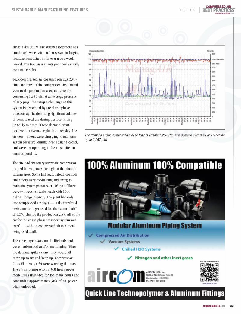
Peak compressed air consumption was 2,957
cfm. One-third of the compressed air demand
went to the production area, consistently
consuming 1,250 cfm at an average pressure
of 105 psig. The unique challenge in this
system is presented by the dense phase
transport application using significant volumes
of compressed air during periods lasting
up to 45 minutes. These demand events
occurred on average eight times per day. The
air compressors were struggling to maintain
system pressure, during these demand events,
and were not operating in the most efficient
manner possible.
The site had six rotary screw air compressor
located in five places throughout the plant of
varying sizes. Some had load/unload controls
and others were modulating and trying to
maintain system pressure at 105 psig. There
were two receiver tanks, each with 1000
gallon storage capacity. The plant had only
one compressed air dryer — a decentralized
desiccant air dryer used for the “control air”
of 1,250 cfm for the production area. All of the
air for the dense phase transport system was
“wet” — with no compressed air treatment
being used at all.
The air compressors ran inefficiently and
were load/unload and/or modulating. When
the demand spikes came, they would all
ramp up to try and keep up. Compressor
Units #1 through #4 were working the most.
The #4 air compressor, a 300 horsepower
model, was unloaded for too many hours and
consuming approximately 30% of its’ power
when unloaded.
The demand profile established a base load of almost 1,250 cfm with demand events all day reaching up to 2,957 cfm.
0 3 / 1 2 |
23 airbestpractices.com
SUSTAINABLE MANUFACTURING FEATURES

Both system assessments reflected this load
profile on the six air compressors. The average
weekly energy consumption was 62,220 kWh
and the energy cost was $4,348. This created
a yearly average energy consumption of
3,235,446 kWh and energy cost of $226,481.
It became clear that with these energy costs,
significant energy savings could be realized
with a compressed air system configuration
designed for this load profile.
The Compressed Air Utility Service Solution by DirectAIR®
The new system was designed to meet the
demand profile. As already illustrated, the
demand profile featured a stable level of 1250
cfm running 24/7. The demand events (spikes)
occur roughly eight times per day and demand
jumps to 2,950 cfm. These demand spikes
were not going to go away.
The DirectAIR system is located right outside
the plant wall. Power was brought to it from a
transformer located right next to the modules.
The DirectAIR system consist of seven
modules. Each module has an air compressor
and a refrigerated air dryer. There is a header
connecting all the units within the module.
The compressors are all managed by the
ManageAIR automation system. The module
has exhaust ports and also openings for heat
recovery systems.
The objective of the new system design was
to have three air compressors optimize the
efficiency of providing compressed air to the
baseload of 1,250 cfm and then have another
three air compressors available to do the
same for the demand spikes — and then shut
to them down and minimize unloaded energy
consumption.
The stable “base load demand” of 1,250 cfm
for the production area is efficiently supplied
by compressor units #2 and #3. They are
running continuously with the variable speed
drive unit #1 trimming the base load of 1250
TABLE 3. DIRECTAIR® AVERAGE WEEKLY AIR COMPRESSOR LOAD PROFILE AND ENERGY COST
UNIT #1 UNIT #2 UNIT #3 UNIT #4 UNIT #5 UNIT #6
FAD* (cfm) 534 534 534 534 534 534
Loaded Time (h) 158 167 78 17 3 0.3
Unloaded Time (h) 0 0.3 7.5 1.3 0.2 0.4
Stopped Time (h) 9.5 0.4 82 149 164 167
Loaded kWh 9,492 16,530 7,738 1,717 326 31
Unloaded kWh 0 14 323 65 15 21
Total kWh 9,492 16,545 8,061 1,781 340 52
Energy Cost ($) $664 $1,158 $564 $125 $24 $4
*Free Air Delivery
PLASTICS PROCESSOR OUTSOURCES COMPRESSED A IR AS THE 4TH UT IL ITY
TABLE 2. AVERAGE WEEKLY AIR COMPRESSOR LOAD PROFILE AND ENERGY COST
UNIT #1 UNIT #2 UNIT #3 UNIT #4 UNIT #5 UNIT #6
FAD* (cfm) 657 464 439 1,447 439 439
Loaded Time (h) 167 20 48 52 4 0.4
Unloaded Time (h) 0 77 119 114 19 22
Stopped Time (h) 1 71 0.6 1 145 145
Loaded kWh 19,997 1,642 3,929 13,855 300 29
Unloaded kWh 0 2,450 2,970 15,749 594 594
Total kWh 19,997 4,092 6,899 29,604 894 623
Energy Cost ($) $1,400 $286 $483 $2,072 $63 $44
*Free Air Delivery
“The system is designed to consume $132,028 in energy costs per year – representing a reduction of $94,453 fromthe original costs of $226,481.”
— Tim Tensing, DirectAIR®
kW
CO2
® | 0 3 / 1 2
24 airbestpractices.com
SUSTAINABLE MANUFACTURING FEATURES

cfm. Each air compressor has a dedicated
refrigerated air dryer and the air will also go
through the decentralized desiccant air dryer
(in the plant) during the winter months.
Air compressors #4, #5, and #6 are set up
to handle the demand spikes and the last one
is off and is the back-up. Each one has its’
own dedicated refrigerated compressed air
dryer. The biggest difference is that the three
air compressors for the spikes are completely
off when not needed (as opposed to being
in the unload mode).
The ManageAIR compressor automation system
controls the machines and one of its’ main goals
is to turn the air compressors off any time they
see more than a couple of minutes of off-load
time. The air compressors will time out and shut
down automatically after a couple of minutes
when the measured pressure stops going down.
The Results
The system is designed to consume $132,028
in energy costs per year — representing a
reduction of $94,453 fromthe original costs
of $226,481. After six months, the DirectAIR®
system is on pace to consume only $115,000
per year in energy costs.
DirectAIR® owns the system and is 100%
responsible for all maintenance and
service costs. The ManageAIR® compressor
automation system runs autonomously and
alerts DirectAIR® service technicians if there
are any issues and when service needs to be
scheduled. The module has a back-up air
compressor (Unit #7) in case any of the
units should go down. DirectAIR® guarantees
100% reliability and pays penalties in the
event that flow, pressure, or dewpoint
guarantees are not met.
Since installation, the plant has reported two
unplanned positives from the system. The first is
that they have typically spent $80,000 per year
on the carbon filters used to treat the wastewater
of the plant. Now that the air compressors are
not contributing oily condensate to the plants’
wastewater system, their spend has dropped to
$40,000 per year.
The second unplanned benefit has been $10,000
reduction on the HVAC natural gas bill due to
the heat recovery package installed
on the air compressors. Additionally, the air
quality from DirectAIR® is dry and more savings
will be realized from the elimination of the
production equipment solenoids maintenance
that was previously caused by wet air.
Treating compressed air as the 4th utility in
the plant is yielding financial benefits for this
plastics processor. The plant pays a fixed fee
for the service plus a compressed air use fee
based upon actual flow consumed. The savings
outlined above have more than paid for all the
fees and no capital is being deployed on new
air compressors.
For more information please contact Tim Tensing, DirectAIR®, tel: 513-539-6763, email: [email protected], www.DirectAIR.com
Together, we can deliver a refrigerated air dryer that will adjust to your energy consumption..saving you money.
1 888 587 9733www.parker.com/faf
Parker Zander’s ecostar Thermal Mass Cycling Refrigerated Air Dryers automatically and precisely adjust energy consumption to your facilities’ operating conditions avoiding unnecessary waste. The ecostar 4-in-1 heat exchanger features the lowest pressure drop in the industry with notable energy savings and a guaranteed dewpoint. Add in ecostar’s integral zero air loss drain and validated Microfilter pre and after filtration and you have the most complete energy savings system available. Parker Zander cycling dryers are currently operating in manufacturing facilities at ranges as high as 27,000 scfm.
TABLE 4. ESTIMATED ANNUAL COST OF OWNERSHIP SAVINGS
Air Compressor Energy Costs $111,000
Contracted Service & Repair Costs $35,000
Maintenance labor costs $15,000
Wastewater Carbon Filters $40,000
Heat Recovery $10,000
Total $211,000 per year
To read moreTo read moreTo read more System Assessment System Assessment System Assessmentarticles, visit www.airbestpractices.com/articles, visit www.airbestpractices.com/articles, visit www.airbestpractices.com/
system-assessmentssystem-assessmentssystem-assessments
®
airbestpractices.com0 3 / 1 2 |
25 airbestpractices.com
SUSTAINABLE MANUFACTURING FEATURES

There are many ways to use storage in
a compressed air system to improve the
performance and repeatability of production
equipment. No one method is a total solution.
Some industry professionals will tell you that
storage is not required for certain types of
compressors. The system, however, can not
afford the impact on either performance or
operating costs. The alternative to applying
storage is to operate at higher pressures with
more power all of the time in order to support
critical applications and the peak air demand
experienced in the system. There are six
basic areas where storage should be properly
engineered and applied in the system. These are:
1. Dedicated storage to improve the speed, thrust, or torque of an application
2. Dedicated storage to protect a critical application from pressure fluctuations
3. Dedicated storage to meter a high rate of flow application into the system
4. General or overhead storage to support applications during the transmission time to the supply side and to create transparency between applications
5. Control storage to support events in the system within an allowable pressure drop
6. Off line, higher pressure air stored to support large system events and reduce peak electrical demand
There are a few fundamental principles which
must be discussed to understand when and
how to apply storage in the system. First,
the article pressure in a system is the
terminating pressure at the actual inlet
connection to the device. It is not at the
regulator or the header, so when someone
says they have to have 90 psig for a particular
device, it is very important to know where they
are monitoring that pressure. This appears
to be a small distinction but it makes a huge
difference in what is required to support
the article. Second, the purpose of the
system is to deliver the required mass of
air to the article within the required time.
Compressed air travels at a limited velocity
inside the system determined by the pressure
differential that exists. At 1 psid, this velocity is
approximately 250 feet/second which means if
the compressors are more than 250 feet away,
they won't see an event which is less than 1
second duration until after it is complete. If
you forget to consider time, the value of these
storage concepts will be very difficult to grasp.
Third, the primary formula for applying
useful storage or capacitance is the capacity
to store times the allowable pressure drop.
For example, if I have a 660 gallon tank and
I can afford to allow the pressure to drop 10
psi then the useful storage is calculated as:
(660 gallons/7.48 gallons/cubic foot)/14.5
psia = 6.07sscf/psi x 10 psi = 60.7 scf of
usable stored air. With these principles in
mind, let's take a look at each of the six
areas where we can apply storage and discuss
the benefits of each case.
Application #1. Dedicated storage to improve the speed, thrust, or torque of an application.
There are many pneumatic applications
which actuate faster than a regulator can
react. The result is a drop in article pressure
which reduces the speed at which the required
mass of air can be delivered. When someone
speaks of this type of application requiring a
certain pressure to work properly, they are
usually referring to the starting pressure not
the terminating pressure. The terminating
pressure, however, is the final article pressure
and is the actual pressure supporting the
application. With actuation speeds of less than
1 second, virtually all of the mass required
for the article will come from storage. With
longer actuation cycles, the mass from storage
will control the pressure drop while flow is
established across the regulator to support
the application. Controlling the amount of
Six Applications for
COMPRESSEDAIR STORAGE
BY DEAN E. SMITH, iZ SYSTEMS
Photo Courtesy of TIGG Tanks.
airbestpractices.com | 0 3 / 1 2
26 airbestpractices.com
SUSTAINABLE MANUFACTURING FEATURES

pressure drop will improve the repeatability
of the application as well as the speed, thrust,
or torque, as applicable. The alternative to
applying storage or capacitance is to increase
the terminating article pressure by cranking the
regulator open to increase the starting pressure.
If the performance is still unacceptable, then
the system pressure is increased. Either solution
increases the available mass but increasing the
pressure has significant operating costs penalties
and will increase the amount of the article
pressure fluctuation. Applying storage reduces
the pressure fluctuation and will allow you to
reduce the header pressure if you are working
on those applications which are dictating the
operating pressure for the system. Remember,
this is one of our fundamental principles: you
can increase the capacity to store or you can
increase the useful pressure differential. The
additional capacitance should be located down
stream of the regulator as depicted in DIAGRAM
#1. The required storage can be calculated by
using a variation of the primary formula:
(the size of the event in cubic ft)
X (atmospheric pressure)/
(the allowable pressure drop) =
(required storage in cubic ft) X (7.48 scf/gal)
= (required storage in gallons)
For example, the volume of storage required
to control the pressure drop of a 0.01 scf
use to 5 psi would be calculated as 0.01 scf
x 14.5 psia/5 psi = .029 scf or .22 gallons.
This would be typical of small, high speed
air cylinders in packaging or assembly
applications.
Application #2. Dedicated storage to protect a critical application from pressure fluctuations.
Another type of a pneumatic application
which can cause high system pressures is
a critical application that must be protected
from fluctuations in header pressure. Often,
this type of application requires relatively low
pressure, such as 60 psig, but the entire system
pressure will be elevated to 95 or 100 psig to
insure that the critical use pressure will remain
above the minimum pressure experienced
in the header. A better solution would be
to increase the capacity to store locally and
dedicate the additional volume to the critical
application with a check valve. For example,
the diaphragm actuator on a fail-closed valve
might require 1 cubic foot of air at 60 psig.
Using the primary formula, the storage volume
required to control the pressure drop to 2 psi
would be:
(1 scf x 14.5 psia/2 psi) = 7.25 scf x
7.48 gal/scf = 54.3 gallons per actuation
The tank should be located upstream of the
regulator and checked from the system as
depicted in DIAGRAM #2. This arrangement
will prevent transient system problems from
impacting the availability of the required air
for the application. In this example, the header
800.223.1325 • www.uesystems.com
Ask us for ourFree Compressed
Air Guide
Introducing the Ultraprobe®
15,000 TouchThe most advancedultrasonic detection systemever created... and it fitsin the palm of your hand!• First ever touch screen inspection technology • Find, record, analyze, and report all leaks • Photograph all test points with on-board camera • Collect exact data needed to analyze leaks,
loss, and carbon footprintIt’s everything you need for seamless,accurate leak detection.Watch a free video demonstration at UESystems.com/products/state-of-the-art-ultrasound-detectors/ultraprobe-15000-touch.aspx
UESEPT/OCTCABPAd 7/26/11 9:19 AM Page 1
®
airbestpractices.com0 3 / 1 2 |
27 airbestpractices.com
SUSTAINABLE MANUFACTURING FEATURES

pressure could be dropped to 72 psig which allows 10 psid across the FRL and still
provides the required mass and pressure for the actuator.
Application #3. Dedicated storage to meter a high rate of flow application into the system.
A variation on this use of storage is to protect the entire system from an intermittent
application which causes header pressure fluctuations when it actuates. In this case,
the storage volume is calculated and installed in the same manner as for protecting
a critical application but a needle valve is installed along with the check valve. Upon
actuation, the receiver provides the mass of air required. The needle valve is adjusted
to control the rate of recovery of the receiver pressure which creates a more constant
and lower rate of flow to the system. For this application to work well, the recovery
time must be equal to or greater than the actuation time. The receiver pressure need
only recover before the next actuation so the use volume can be spread out over
the entire cycle time. For example, reverse pulse baghouses pulse on solenoids with
open times less than 0.25 seconds. While the total volume of air required will only be
approximately 2 cubic feet, the rate of flow created is 480 scfm (2 scf x 60 sec/0.25
sec). This high rate of flow will cause the header pressure to drop with each pulse and
S I X A P P L I C A T I O N S F O R C O M P R E S S E D A I R S T O R A G E
ENERGY KAIZEN EVENTS
Get your FREE Subscription to Compressed Air Best Practices® Magazine to learn how to save energy.
Subscribe at
p Food Packaging Plant Saves $70,000 or 1.1 Million kWh per year.p Paper Mill Saves $207,000 or 4.5 Million kWh per year.
airbestpractices.com
0 3 / 1 2
28 airbestpractices.com
SUSTAINABLE MANUFACTURING FEATURES

11510 Goldcoast DriveCincinnati, Ohio 45249-1621(800) 903-9247/fax: (513) 671-3363www.exair.com
111111111111111111111111111111111111111111111111111111111111111111111111111111111111111111111111111111111111111111111111111111111111111111111111111111111111111111111111111111111111111111111111111111111111111111111111111111111111111111111111111111111111111111111111111111
2222222222222222222222222222222222222222222222222222222222222222222222222222222222222222222222222222222222222222222222222222222222222222222222222222222222222222222222222222222222222222222222222222222222222222222222222222222222222222222222222222222222222222222222222222222222222222222222222222222222222222222222222222222222222222222222
333333333333333333333333333333333333333333333333333333333333333333333333333333333333333333333333333333333333333333333333333333333333333333333333333333333333333333333333333333333333333333333333333333333333333333333333333333333333333333333333333333333333333333333333333333333333333333333333333333333333333333333333333333333333333333333333333333333333333333333333333333333333333333333333333333333333333333333333333333333333333333333333333333333333333333333333333333333333333333333333333333333333333333333333333333333333333333333333333333333333333333333333333333333333333333333333333333333333333333333
44444444444444444444444444444444444444444444444444444444444444444444444444444444444444444444444444444444444444444444444444444444444444444444444444444444444444444444444444444444444444444444444444444444444444444444444444444444444444444
55555555555555555555555555555555555555555555555555555555555555555555555555555555555555555555555555555555555555555555555555555555555555555555555555555555555555555555555555555555555555555555555555555555555555555555555555555555555555555555555555555555555555555555555555555555555555555555555555555555555555555555555555555555555555555555555555555555555555555555555555555555555555555555555555555555555555
EXAIR’s Digital Flowmeter™ accurately measures compressed air usage and monitors waste. Trends can be monitored to find excessive air use. Detects leaks at compressed air fittings when the machinery is off. Regular monitoring can detect leaks that develop as the machinery ages.
• Easytoinstall-Noadjustmentsorcalibrationsneeded• Digitalreadoutdisplaysactualairflowthroughpipe
www.exair.com/78/4dfm.htm111111111111111111111111111111111111111111111111111111111111111111111111111111111111111111111111111111111111111111111111111111111111111111111111111111111111111111111111111111111111111111111111111111111111111111111111111111111111111111111111111111111111111111111111111111111111111111111EXAIR’s Ultrasonic Leak Detector can help you identify costly leaks in your compressed air system. Leaks can account for 30% of total compressor output! In many cases, finding one small leak can quickly pay for the leak detector.
• Detectsleaksupto20’(6.1m)away• Accurateinnoisyindustrialenvironments
www.exair.com/78/496.htm222222222222222222222222222222222222222222222222222222222222222222222222222222222222222222222222222222222222222222222222222222222222222222222222222222222222222222222222222222222222222222222222222222222222222222222222222222222222222222222222222222222222222222222222222222222222222222222222222222222222222222222222222222222222222222222222222222222222222222222222222222222222222222222222222222222222222222222222222222222222222222222222222222222222222222222222222222222222EXAIR’s award winning Super Air Knives™, Super Air Nozzles™, and Super Air Amplifiers™ entrain large volumes of room air using only a small amount of compressed air as the power source. They dramatically reduce air consumption and noise.
• Lowcost-Replacesnoisyblowers• Improvesblowoffperformanceandsafety
www.exair.com/78/423.htm
compressed air as the power source. They dramatically reduce
333333333333333333333333333333333333333333333333333333333333333333333333333333333333333333333333333333333333333333333333333333333333333333333333333333333333333333333333333333333333333333333333333333333333333333333333333333333333333333333333333333333333333333333333333333333333333333333333333333333333333333333333333333333333333333333333333333333333333333333333333333333333333333333333333333333333333333EXAIR’s EFC™ is an electronic flow control that minimizes compressed air use by turning off the compressed air when no part is present. For use on blowoff, drying, cooling, conveying and static elimination operations.
• Easyhookup100-240VACwithcompacteightfunctiontimer
• Photoelectricsensorwithstandswateranddustwww.exair.com/78/4efc.htm44444444444444444444444444444444444444444444444444444444444444444444444444444444444444444444444444444444444444444444444444444444444444444444444444444444444444444444444444444444444444444444444444444444444444444444444444444444444444444444444444444444444444444444444444444444444444444444444444444444444444444444444444444444444444
An EXAIR 60 gallon Receiver Tank can be installed at the point of high demand so there is an additional supply of compressed air available for a short duration. Meets ASME pressure vessel code.
• Eliminatesfluctuationsinpressureandvolume• Vertical,spacesavingdesign
www.exair.com/78/4tank.htm55555555555555555555555555555555555555555555555555555555555555555555555555555555555555555555555555555555555555555555555555555555555555555555555555555555555555555555555555555555555555555555555555555555555555555555555555555555555555555555555555555555555555555555555555555555555555555555555555555555555555555555555555555555555555555555555555555555555555555555EXAIR Pressure Regulators permit easy selection of an operating pressure that will allow the air product to work properly without using excessive amounts of compressed air. Reducing the air pressure from 100 PSIG to 80 PSIG reduces energy use by almost 20%.
• Modulardesignpressuregauge• Manysizesavailable
www.exair.com/78/4reg.htm66666666666666666666666666666666666666666666666666666666666666666666666666666666666666666666666666666666666666666666666666666666666666666666666666666666666666666666666666666666666666666666666666666666666666666666666666666666666666666666666666666666666666666666666666666666666666666666666666666666666666666666666666666666666666666666666
66666666666666666666666666666666666666666666666666666666666666666666666666666666666666666666666666666666666666666666666666666666666666666666666666666666666666666666666666666666666666666666666666666666666666666666666666666666666666666666666666666666666666666666666666666666666666666666666666666666666666666666666666666666666666666666666666666666666666666666
Save thousands of dollars by dramatically cutting energy costs!It’s a worldwide problem that can’t be fixed with a bandage, a piece of chewing gum, or duct tape. If you follow these easy steps, EXAIR can help you make your system energy efficient so your company pays the lowest price possible for compressed air.
Six Steps To Optimizing Your Compressed Air System
Measure the air consumption to find sources that use a lot of compressed air.
Find and fix the leaks in your compressed air system.
Upgrade your blowoff, cooling and drying operations using EXAIR engineered compressed air products.
Turn off the compressed air when it isn’t in use.
Use intermediate storage of compressed air near the point of use.
Control the air pressure at point of use to minimize air consumption.
@EXAIR

From more large-scale, running machines than ever before to solutions that cover the entire plastics industry lifecycle, the advancements that deliver a competitive advantage can only be found this April at NPE2012, the world’s largest plastics conference, exposition and technology exchange. Join your peers in Orlando to Break the Mold — and reshape the paradigms that will lead to a more successful future. Showcasing innovations from more than 2,000 globally focused exhibitors, NPE features:
Don’t wait — connect with the entire lifecycle of plastics this year and uncover the solutions needed to move your company, products and career forward.
ATTEND NPE2012!
Orange County Convention CenterOrlando, Florida USA
The International Plastics ShowcaseApril 1– 5, 2012 | www.npe.org
Co-located at NPE2012:
2+ million square feet of tomorrow’s solutions, today
More large-scale, running machines in action
Interaction with 75,000 industry peers from more than 120 countries
Access to hundreds of timely educational programs and daily emerging technology demos
And much, much more!
READY TO RESHAPE YOUR FUTURE
REGISTER NOW AT NPE.ORG
8.375x10.875.indd 1 05/01/12 2:41 PM
could cause more critical users in the vicinity
to require a higher pressure than otherwise
necessary. The pulse occurs every few minutes
so the recovery of the receiver pressure can be
metered in easily over 15 seconds which will
reduce the rate of flow to 8 scfm (2 scf x 60
sec/15 sec). This significantly reduces the peak
in air demand caused by such applications
and will reduce the on line compressor
horsepower correspondingly.
Application #4. General or overhead storage to support applications during the transmission time to the supply side and to create transparency between applications.
To appreciate the value of general storage,
you must keep the time component in mind.
When a large user enters the system, air
flows toward the application drawing down
the pressure in the surrounding header.
The increase in air demand moves outward
at 250 feet per second until it reaches
the compressor signal location. When the
compressors respond with adequate power
and increased delivery, the pressure decay
will stop. The amount of pressure drop
which will be seen in the header is directly
related to the storage volume in the header,
the size of the event, and the distance from
the event to the supply. Assume the largest
event is the start up of a 600 scfm application
located 1000 feet in header distance from
the compressor room. This application will
remove air from the header for 4 seconds
(1000 ft/250 fps) at a rate of 10 scf/sec (600
scfm/60 sec). At that point, the event will have
reached the compressor room and the supply
can respond with storage or power. Assuming
we want to control the pressure drop to less
than 2 psi, the storage requirement would be
(4 sec x 10 scf/s) = 40 scf x 14.5 psia/2 psi
= 290 scf x 7.48 gal/scf = 2,169 gallons. You
can subtract the existing volume contained
in the header piping from this figure if it is
significant. Adding receivers to the header
is the most economical means of increasing
the storage volume. These receivers should
be spooled in near the large events; it is
not necessary to "flow through" the tank. In
many systems the largest coincidental event
will be shift start up when most users hit the
system at very close to the same time. The
alternative to adequate general storage is to
raise the header pressure until the largest
pressure fluctuations don't impact the highest
critical use pressure. Unfortunately, as the
pressure increases so does the demand for
air in all unregulated uses such as leaks,
open blowing, and users with the regulator
cranked all the way open. This phenomenon
is called artificial demand and it prevents the
compressors from being able to equalize the
pressure throughout the header. Eventually,
the pressure rises to the modulation or
unload setpoint on the compressor or in
systems with high levels of artificial demand,
the system actually absorbs the increased
flow and the pressure stabilizes before the
compressor unloads.
Application #5. Control storage to support events in the system within an allowable pressure drop.
If you have been around compressed air
very long, you have heard, “... this type
of compressor does not require a tank...”.
The compressor may not need the tank,
but the system sure does! Consider a typical
500 hp rotary screw compressor system with
1,500 feet of 6" headers, 3" subheaders and
no tank in a manufacturing plant. The total
capacitance will be less than 19 scf/psi which
is calculated by dividing the total volume of the
piping by the atmospheric pressure (similar
to the storage formulas above). If the system
is operating two 200 hp and one 100 hp
compressors, the failure of a 200 hp base load
unit will result in a loss of approximately 1000
scfm or 16.7 scf/sec supply. The pressure will
drop at a rate of .88 psi/sec (16.7 scf/s/19 scf/
psi) which means in 20 seconds the pressure
will drop 17 psi. The first time this kind of
pressure decay occurs, it is a pretty safe bet
that production will be impacted and the
backup compressor will be turned on and left
on. To properly manage the system during a
compressor failure, we must provide adequate
storage in the compressor room to allow the
backup compressor to autostart. This control
permissive time varies from 10 seconds for
rotary screws with full voltage starters to 120
seconds for many centrifugal compressors.
The event volume that must be supported
from storage will be the rate of flow in scf/
sec times the control permissive time of the
backup compressor. As we have demonstrated,
“If you have been around compressed air very long, you have heard, ‘... this type of compressor does not require a tank...’. The
compressor may not need the tank, but the system sure does!”— Dean E. Smith, iZ Systems
kW
CO2
S I X A P P L I C A T I O N S F O R C O M P R E S S E D A I R S T O R A G E
® | 0 3 / 1 2
30 airbestpractices.com
SUSTAINABLE MANUFACTURING FEATURES

From more large-scale, running machines than ever before to solutions that cover the entire plastics industry lifecycle, the advancements that deliver a competitive advantage can only be found this April at NPE2012, the world’s largest plastics conference, exposition and technology exchange. Join your peers in Orlando to Break the Mold — and reshape the paradigms that will lead to a more successful future. Showcasing innovations from more than 2,000 globally focused exhibitors, NPE features:
Don’t wait — connect with the entire lifecycle of plastics this year and uncover the solutions needed to move your company, products and career forward.
ATTEND NPE2012!
Orange County Convention CenterOrlando, Florida USA
The International Plastics ShowcaseApril 1– 5, 2012 | www.npe.org
Co-located at NPE2012:
2+ million square feet of tomorrow’s solutions, today
More large-scale, running machines in action
Interaction with 75,000 industry peers from more than 120 countries
Access to hundreds of timely educational programs and daily emerging technology demos
And much, much more!
READY TO RESHAPE YOUR FUTURE
REGISTER NOW AT NPE.ORG
8.375x10.875.indd 1 05/01/12 2:41 PM

useful storage or capacitance is the capacity to
store times the allowable pressure drop. But
we have been attempting to minimize system
pressure, so how do we provide adequate
storage without increasing the system pressure
and incurring the associated higher operating
cost? What we require is a means of separating
the demand side from the supply side of the
system. This is the function of a demand
expander or flow controller.
A flow controller allows the system to operate
at maximum efficiency by controlling the
expansion of the air down to the lower
header pressure. This minimizes waste and
achieves more consistent and reliable results.
On the supply side, the compressors can be
operated at the design pressure which achieves
maximum mass delivered per kW consumed.
The difference between the two pressures
eliminates artificial demand and creates true
usable storage in the system. When a demand
event occurs in the system, the controller
will respond by modulating the flow control
valve to match the down stream requirements.
This is very different from a regulator in that
it does not introduce an energy loss in the
system but rather controls expansion across
the valve to match the demand and maintain
a fixed pressure on the demand side. Looking
back at the 500 hp system example, we can
increase the value of a receiver dramatically
with the flow controller in place by increasing
the supply to the design pressure which will
be 125 psig for our example. If we add a
5000 gallon (668 scf) receiver to the system
and operate the demand at 75 psig, we can
calculate the usable storage
as: (668 scf/14.5 psia) x
(125–75 psig) = 2,300
scf. This stored air can be
accessed by the system at
any rate of flow at any time
without increasing the online
horsepower. In the case of
the failure of the 200 hp
compressor, the pressure
will now drop at 0.36 psi/sec
(16.7 scf/sec/668 scf/14.5
psia). Now in 20 seconds, the
pressure will only drop 7.2
psi on the supply side of the
expander and the demand
side pressure will not have
changed at all. In a non-
automated system, the autostart set
point could be set approximately 10 psi above
the expander setpoint. This would provide
ample time to autostart a backup rotary
screw compressor with control permissives
of 10-20 seconds before the demand pressure
would be impacted. In fact, the storage can
support the demand after the loss of the 200
hp compressor for over 2 minutes ((125–75
psig)/0.36 psi/sec) before there would be any
impact on the demand side pressure.
Application #6. Off-line, higher pressure air to support large system events and reduce peak electrical demand.
There is another method for supporting large
intermittent system events or compressor
failures. This involves the use of higher
pressure off line storage very similar in
concept to a water tower. A water tower is
supplied by smaller horsepower pumps that
run continually to pump water up to the
elevated tank. When peaks in demand occur,
the water in the tank can be added to the on
line system at almost any rate of flow without
turning on large horsepower pumps. Each
off-line, high pressure air system must be
engineered and applied to the requirements
of the specific system but typically will consist
of two 10–20 hp compressors delivering air at
>200 psig to a 10,000–20,000 gallon receiver
which is isolated form the header system by
a control valve arrangement. A flow controller
and a PLC based automation system which
constantly monitors the rate of change in the
system are required to make off-line, high
pressure air function properly. The automation
“The next time someone complains about insufficient air pressure, remember there are alternatives to raising the pressure and buying or operating another compressor.”
— Dean E. Smith, iZ Systems
kW
CO2
S I X A P P L I C A T I O N S F O R C O M P R E S S E D A I R S T O R A G E
®
.com | 0 3 / 1 2
32 airbestpractices.com
SUSTAINABLE MANUFACTURING FEATURES

To read more To read more To read more System AssessmentSystem AssessmentSystem Assessment articles, articles, articles, System Assessment articles, System AssessmentSystem AssessmentSystem Assessment articles, System Assessment articles, System Assessment articles, System AssessmentSystem AssessmentSystem Assessment articles, System Assessmentvisit www.airbestpractices.com/system-visit www.airbestpractices.com/system-visit www.airbestpractices.com/system-
assessments/piping-storageassessments/piping-storageassessments/piping-storage
system will open the high pressure air control
valve and introduce the stored air into the
header to support the event. The control of
this process is critical because if the stored
air causes the pressure to rise, base load
compressors will unload which would lead
to a system collapse when the high pressure
air storage is exhausted. At the end of the
system event, the automation system will close
the control valve and begin recovery of the
pressure in the 20,000 gallon receiver with the
20 hp units which produce approximately 75
scfm each. The 200 psig compressors depicted
in DIAGRAM #3 are standard equipment
available from several major manufacturers
as single stage rotary screw units.
Off-line, high pressure air is useful to
protect systems which are ultra-critical due
to financial or safety issues. However, the
primary reason for most systems is to avoid
running a large, base load compressor to
support large demand events or to support
a large system during a compressor failure.
For example, in centrifugal based systems
there is almost always an extra compressor
operating to support the system when a
compressor fails or surges. This is due to the
control permissives which can be 120 seconds
and makes control storage impractical. For
example, if the compressor that fails is 700
hp and 3,000 scfm or 50 scf/sec, the storage
will have to support 6,000 cubic ft (120 sec
x 50 scf/s). A 20,000 gallon receiver provides
184.4 scf/psi (20,000 gal/7.48 scf/psi/14.5
psia). Dividing the 6,000 scf requirement
by the 184.4 scf/psi capacitance determines
that the pressure will drop 32.5 psi to 142.5
psig in the high pressure air receiver. After
the backup compressor starts and the high
pressure air valve closes, the recovery of the
receiver pressure will begin. Dividing the total
event of 6,000 scf by the output of the high
pressure air compressors at 75 scfm each
indicates 80 minutes would be required if
both compressors ran or 160 minutes for one
compressor. The initial cost of this system will
be a fraction of the cost of a backup 700 hp
compressor and will obviously be much less
expensive to operate when required.
Conclusion
By applying the basic storage principles
involved in a compressed air system, you
can immediately improve the performance of
production equipment in terms of productivity
and quality, and make major reductions in
the operating costs of your compressed air
system. The alternative to applying these basic
storage principles in the system is to operate
too much pressure and power all of the time
to compensate for the lack of storage. The next
time someone complains about insufficient air
pressure, remember there are alternatives to
raising the pressure and buying or operating
another compressor.
Dean Smith is the General Manager of iZ Systems, a consulting firm specializing in auditing and designing compressed air systems, and was formerly the Principal of Air Management, Atlanta, GA. He is a member of the Technology Core Group which wrote the training materials for the Compressed Air Challenge of the DOE. He has performed complete system audits on over 1,000 plant compressed air systems providing recommendations that have improved quality and productivity while reducing plant operating costs. For further information, Mr. Smith can be reached at 404-307-6836 or email at [email protected].
5215 21st Street Racine, Wisconsin 53406-5096 (262) 554-8330 [email protected] thermaltransfer.com
We COOL what you POWER
TTP5468 CABP Ad March2012.indd 1 2/10/12 4:58 PM
®
airbestpractices.com0 3 / 1 2 |
33 airbestpractices.com
SUSTAINABLE MANUFACTURING FEATURES

THE DEMAND-SIDE TECHNOLOGY PROVIDER THE DEMAND-SIDE TECHNOLOGY PROVIDER THE DEMAND-SIDE TECHNOLOGY PROVIDER THE DEMAND-SIDE TECHNOLOGY PROVIDER THE DEMAND-SIDE TECHNOLOGY PROVIDER THE DEMAND-SIDE TECHNOLOGY PROVIDER
Pneumatic and Vacuum Energy Optimization On OEM MachinesBY PHILIP O’NEILL, BOSCH REXROTH CORPORATION – PNEUMATICS DIVISION
The push to achieve reductions in energy consumption is a significant global trend. Many companies have begun offering incentives to employees to reduce cost and achieve higher energy efficiency. In some regions of the U.S., companies can profit from rebates given by electric power suppliers for reductions in compressed air usage.
Machine builders aiming to improve the energy efficiency of their machines tend to focus on using energy media other than Pneumatics (typically Electro-Mechanical or Hydraulic) since Pneumatics, as traditionally applied, is viewed as inefficient due to factors like leakage and over-pressurization (i.e.: supplying a higher pressure in an actuator to accomplish a task which is endemic in practice). But
they shouldn’t. When generating and using compressed air, it’s true that there are many places in the system where energy can be lost, however targeted measures within a comprehensive energy saving concept can prevent these losses and significantly reduce energy consumption at the machine level.
Consider the following tactics to avoid dead volumes and optimize the use of compressed air:
Bigger Not Always Better
On new machine applications, correct component dimensions are a great start to obtain optimal energy usage. With pneumatic components, bigger doesn’t mean better when over-dimensioning leads to unnecessarily high
air consumption. It is common practice to assume “when in doubt, go one size bigger,” or to re-use designs that were selected and worked on previous projects even though they may be overkill in terms of space and weight on the machine. This causes avoidably high air consumption and costs more to purchase and operate.
Reducing cylinder diameters helps to save air volume. The use of online configuration tools, calculation programs, and energy saving calculators help determine what component dimensions are needed for the application.
In one lumber industry application, a sawmill machine’s output increased 13% by simply reducing the size of the pneumatics used on the sorter gates of the machine. The cylinder bore was reduced from 3.25" to 2", ½" air valves were reduced to ¼", and pressure was reduced from 100 psi to 60 psi. With these seemingly minor alterations, the company effectively increased its production speed, and achieved energy savings of 75% on the machine.
What about OEMs that build standard machines and sell to a variety of end-users? In order to mass-produce a standard machine, it needs to be designed and sized to accommodate the end-user with the lowest available pressure. This usually means specifying larger, more expensive components, resulting in increased air consumption. This issue can partially be solved by ensuring that the supply pressure to the machine is regulated down to the design pressure level. It is common for operators to increase supply pressure on Regulators in the hope of improving performance but this ends up costing the end-user significant amounts of money in operating costs for no actual benefit
When generating and using compressed air in industrial machines, targeted measures within a comprehensive energy saving concept can significantly improve energy efficiency at the machine level.
® | 0 3 / 1 2
34 airbestpracticesairbestpractices.com
SUSTAINABLE MANUFACTURING FEATURES

When you partner with the global leader in compressed air pipe systems, expect to move your business and the world forward. From various fittings to highly integrated pipe systems, Transair’s aluminum pipe ensures higher longevity of equipment and avoids frequent changes of filtration elements. Not to mention, Transair’s energy savings element is critical to lowering your overall cost of ownership. So partner with Parker, and get ready to move clean air, guaranteed.
Together, we can move clean air, guaranteed. From the compressor outlets to the machines with optimal flow, minimal downtime and increased plant productivity.
www.parkertransair.com ph 480 830 7764
Scan with your mobile device to see a Transair
video.
Compressed air pipe systems 1/2” to 6”
if the components were sized correctly. It is important to monitor machine system pressure to ensure that it is within both a minimum AND a maximum value to avoid energy waste.
Pressure Regulation — Use Only What is Required
Best practices of lean manufacturing call for the elimination of any waste that does not add value to the product or process at hand. With pneumatics, energy is frequently wasted in this manner when too much pressure is applied for tasks that do not require that equivalent level of force. This can be overcome by using pressure regulators in pneumatic cylinders to control exactly when to exert energy and when to conserve it. By applying the exact amount of pressure needed for each task, machines can realize energy savings of up
to 40% in many cases. It is important to note that Pressure Regulators installed between a valve and cylinder are capable of operating with “reverse-flow” which are becoming increasingly common and lower in cost- usually much more economical and easier to install than traditional sandwich pressure regulators. Many standard in-line Pressure Regulators do not have this functionality
and in such cases a check-valve is required in parallel to accommodate the reverse flow.
In many applications, there is either a “push” or “pull” load but not both. Most often, the
Cycle time reduction for different strokes: 2 bar compared to 6 bar as “no-load” pressure.
Stroke time with different “no-load” pressures.
®
.com0 3 / 1 2 |
35 airbestpractices.com
SUSTAINABLE MANUFACTURING FEATURES
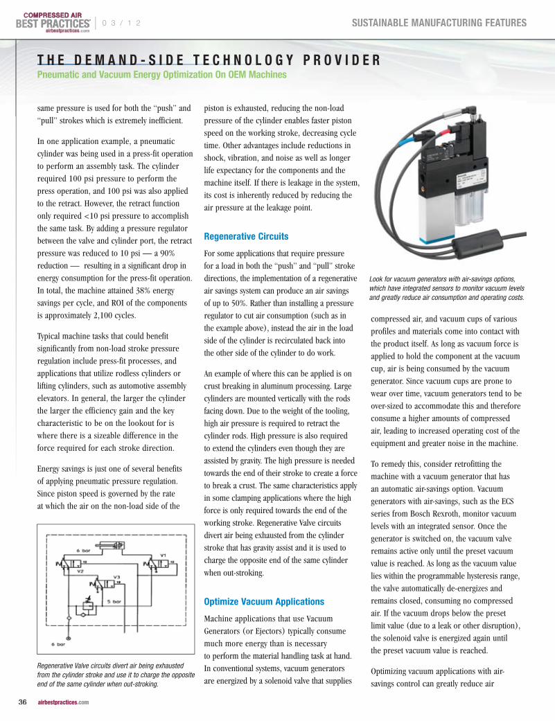
T H E D E M A N D - S I D E T E C H N O L O G Y P R O V I D E R Pneumatic and Vacuum Energy Optimization On OEM Machines
same pressure is used for both the “push” and “pull” strokes which is extremely inefficient.
In one application example, a pneumatic cylinder was being used in a press-fit operation to perform an assembly task. The cylinder required 100 psi pressure to perform the press operation, and 100 psi was also applied to the retract. However, the retract function only required <10 psi pressure to accomplish the same task. By adding a pressure regulator between the valve and cylinder port, the retract pressure was reduced to 10 psi — a 90% reduction — resulting in a significant drop in energy consumption for the press-fit operation. In total, the machine attained 38% energy savings per cycle, and ROI of the components is approximately 2,100 cycles.
Typical machine tasks that could benefit significantly from non-load stroke pressure regulation include press-fit processes, and applications that utilize rodless cylinders or lifting cylinders, such as automotive assembly elevators. In general, the larger the cylinder the larger the efficiency gain and the key characteristic to be on the lookout for is where there is a sizeable difference in the force required for each stroke direction.
Energy savings is just one of several benefits of applying pneumatic pressure regulation. Since piston speed is governed by the rate at which the air on the non-load side of the
piston is exhausted, reducing the non-load pressure of the cylinder enables faster piston speed on the working stroke, decreasing cycle time. Other advantages include reductions in shock, vibration, and noise as well as longer life expectancy for the components and the machine itself. If there is leakage in the system, its cost is inherently reduced by reducing the air pressure at the leakage point.
Regenerative Circuits
For some applications that require pressure for a load in both the “push” and “pull” stroke directions, the implementation of a regenerative air savings system can produce an air savings of up to 50%. Rather than installing a pressure regulator to cut air consumption (such as in the example above), instead the air in the load side of the cylinder is recirculated back into the other side of the cylinder to do work.
An example of where this can be applied is on crust breaking in aluminum processing. Large cylinders are mounted vertically with the rods facing down. Due to the weight of the tooling, high air pressure is required to retract the cylinder rods. High pressure is also required to extend the cylinders even though they are assisted by gravity. The high pressure is needed towards the end of their stroke to create a force to break a crust. The same characteristics apply in some clamping applications where the high force is only required towards the end of the working stroke. Regenerative Valve circuits divert air being exhausted from the cylinder stroke that has gravity assist and it is used to charge the opposite end of the same cylinder
when out-stroking.
Optimize Vacuum Applications
Machine applications that use Vacuum Generators (or Ejectors) typically consume much more energy than is necessary to perform the material handling task at hand. In conventional systems, vacuum generators are energized by a solenoid valve that supplies
compressed air, and vacuum cups of various profiles and materials come into contact with the product itself. As long as vacuum force is applied to hold the component at the vacuum cup, air is being consumed by the vacuum generator. Since vacuum cups are prone to wear over time, vacuum generators tend to be over-sized to accommodate this and therefore consume a higher amounts of compressed air, leading to increased operating cost of the equipment and greater noise in the machine.
To remedy this, consider retrofitting the machine with a vacuum generator that has an automatic air-savings option. Vacuum generators with air-savings, such as the ECS series from Bosch Rexroth, monitor vacuum levels with an integrated sensor. Once the generator is switched on, the vacuum valve remains active only until the preset vacuum value is reached. As long as the vacuum value lies within the programmable hysteresis range, the valve automatically de-energizes and remains closed, consuming no compressed air. If the vacuum drops below the preset limit value (due to a leak or other disruption), the solenoid valve is energized again until the preset vacuum value is reached.
Optimizing vacuum applications with air-savings control can greatly reduce air
Regenerative Valve circuits divert air being exhausted from the cylinder stroke and use it to charge the opposite end of the same cylinder when out-stroking.
Look for vacuum generators with air-savings options, which have integrated sensors to monitor vacuum levels and greatly reduce air consumption and operating costs.
® | 0 3 / 1 2
36 airbestpractices.com
SUSTAINABLE MANUFACTURING FEATURES

Dew Point - Humidity - Oxygen
Michell Instruments, Inc319 Newburyport Turnpike, Suite 207, Rowley, MA 01969Tel: 978 484 0005, [email protected]
www.michell.com/us
DON’T LOSE CONTROL OF YOUR COMPRESSED AIR MOISTURE!
Avoid:• Lost production• Out-of-spec product• Equipment damage
Prevent costly downtime by measuring compressed air moisture with the Michell Easidew
• Fully calibrated dew-point transmitter• Low cost to install and operate• As easy as temperature and pressure measurement
See full product specifi cation
consumption and operating cost. Vacuum generators with air-saving functions can be easily installed or retrofitted to improve efficiency. Other tangible benefits include significant noise reduction on equipment due to increased off-time of the vacuum valve. Furthermore, the frequency of vacuum sensor activation can be used as an indicator of both
wear and overall efficiency of the system.
Minimize Leaks, Control “Off-Duty” Air Pressure
Leaks are costly. For end users seeking to
improve the efficiency of the pneumatics on
their machines, the low-hanging fruit is finding
and fixing leaks.
Leakage can commonly be attributed to factors
such as valve design and the deterioration
of seals. Some valve designs, such as lapped
spool valves with metal sealing, have inherent
internal leakage up to 700cc/min even when
brand new. The leak is constant as long as
there is air supplied to the valve. Switching
to comparable valves with soft seals instead
of metal seals can cut the allowable leak limit
to between 10 and 30cc/min.
Leakage can also be caused by chemicals
in the air system that are incompatible
with industrial elastomeric seals. The first
component to fail due to incompatible
chemicals in the air supply is the pressure
regulator. If deterioration of elastometric Buna
seals occurs, consider installing an active
carbon filter bed or lubricator, or switching
to devices with non-Buna seals such as HNBR,
Viton, Teflon, Hard Sealing, or Polyurethane.
The implementation of automatic air reduction
control is another means of significantly
increasing machine efficiency. Most existing
machine installations have no automatic
means of shutting off air to machines when
not in use, and having maintenance personnel
individually turn off air to specific machines
is too cumbersome. Some machines may
require pressure for certain functions to be
supplied even after the machine is turned off
and there is no production (examples include
air bearings, air gauging and cleaning).
Frequently however, these functions can be
satisfied with greatly reduced supply pressure
or with pressure for a limited time period.
If a plant has two shifts/five days a week, an
automatic air reduction control package can
be added to automatically reduce the supply
pressure during the hours that the plant is not
®
.com0 3 / 1 2 |
37 airbestpractices.com
SUSTAINABLE MANUFACTURING FEATURES

in operation. In the event that higher pressure
is required during off-hours, the system can
be overridden.
Decentralize the Valving
Centralized valve manifolds not only have
the reputation of being cumbersome and
using long air lines, they also consume a
lot of energy. Small, decentralized valve units
with competence and intelligence at the site
of the application offer greater efficiency.
The concentration of pneumatic functions
prevents pressure losses through long lines
from the control cabinet to the pneumatic
drive. Tubing connections can be significantly
reduced (by 50%) by using valve/actuator
units, resulting in an energy saving of 35%.
Manufacturers of pneumatic components
now offer smaller, lighter, chemical-resistant
valves — thanks to special polymers — that
can be mounted right next to the actuator.
This direct connection of valves and cylinders
eliminates pressure losses, which arise from
long connection lines. Decentralization of the
system can also yield faster response times,
and higher cycle frequencies.
Modern valves and manifolds are available
with IP69K protection and sanitary design with
materials that are suitable for food processing.
This eliminates the need for the traditional
locating of pneumatic valves in remote stainless
steel enclosures with long tubes in between.
The energy savings is gained by the elimination
of over 50% the tubes and improved response
time due to the valve being located where the
actual work is being done.
The Bottom Line
On a plant-wide level, steps to achieve greater
energy efficiency can certainly be implemented,
but end users should work with their OEMs
to consider what steps can be taken at the
machine level. Energy costs comprise more
than half the total cost of ownership in
pneumatics today, and a constructive evaluation
of pneumatic applications will quickly pay off.
Every application is different, and the overall
machine concept and types of components
used influence the potential for energy savings.
Pneumatics should be considered in the
strategy to achieve greater energy efficiency
in industrial machinery.
For more information on energy-saving tips using Bosch Rexroth pneumatic components, and to download the "Energy Efficiency in Pneumatics" brochure, visit www.boschrexroth-us.com/sustainable.
For more information contact Phil O’Neil, Product Manager-Standard Products, Bosch Rexroth Corp. — Pneumatics, tel: 859-281-3426, email: [email protected], www.boschrexroth-us.com
To read more To read more To read more Pneumatics Pneumatics Pneumatics System Assessment System Assessment System Assessment articles, visit articles, visit articles, visit www.airbestpractices.com/system-www.airbestpractices.com/system-www.airbestpractices.com/system-
assessments/pneumaticsassessments/pneumaticsassessments/pneumatics
Special polymers allow for smaller, lighter, chemical-resistant valves — like the LS04 valve from Bosch Rexroth — that can be mounted right next to the actuator.
Pneumatics optimization can yield significant gains in energy efficiency in industrial machinery. Consider these tactics to avoid dead volumes and optimize the use of compressed air:
• Bigger isn’t better — size components exactly and correctly
• Apply pressure regulators to cylinders with no-load strokes
• Consider regenerative circuits when there is load in both stroke directions
• Optimize vacuum applications
• Minimize leaks, control off-duty air consumption
• Decentralize the valving
End users should incentivize OEMs to design equipment that reduces the total cost of ownership, and explore what steps can be taken at the machine level to achieve maximum energy efficiency.
kW
CO2
T H E D E M A N D - S I D E T E C H N O L O G Y P R O V I D E R Pneumatic and Vacuum Energy Optimization On OEM Machines
®
.com | 0 3 / 1 2
38 airbestpractices.com
SUSTAINABLE MANUFACTURING FEATURES

INTERNATIONAL WIRE TR IMS COMPRESSED A IR COSTS US ING THE “SYSTEMS APPROACH”
BY TOM TARANTO AND RAM KONDAPI FOR THE COMPRESSED AIR CHALLENGE®
International Wire Group, Inc. (IWG)
headquartered in Camden, NY is the largest
bare copper wire and copper wire products
manufacturer in the United States with
expanding operations in Europe. Products
include a broad line of copper wire
configurations and gauges with a variety
of electrical and conductive characteristics,
which are utilized by a wide variety of
customers primarily in the industrial and
energy, electronics, data communications,
aerospace and defense, medical electronics
and devices, automotive, and consumer
and appliance industries.
IWG culture is one of continuous improvement,
and customer satisfaction on the basis
of quality, reliability, price, reputation,
customer service, and on-time delivery.
Advanced quality assurance and testing
equipment plus continuous improvement
upgrades and investments to manufacturing
equipment ensures products will consistently
meet customers' specifications and quality
requirements.
The IWG Plant Engineering team members
recognized that the compressed air system
was a major energy user in the plant and
its performance directly impacted the
manufacturing process and product quality.
Team members, Dave Sherwood, Tom Lewis,
Eric Bryant, and John Hoyt represent a cross
section of plant management, production,
engineering, and R&D. The key to success was
the interactive spirit of cooperation to prepare
for the assessment, experiment with process
modifications, and respond to challenges
with the expertise and determination
to troubleshoot and overcome obstacles
necessary resulting in the successful outcome
for the project.
The plant operates six high speed production
lines that draw copper wire and plate the
wire to exacting customer specifications.
The continuous high speed plating lines pass
wire through various liquid chemical process
Join us for the next four-part session of Fundamentals of
Compressed Air Systems WE (web-edition) coming May 2nd.
Led by our experienced instructors, this web-based version
of the popular Fundamentals of Compressed Air Systems
training uses an interactive format that enables the instructor
to diagram examples, give pop quizzes and answer questions
in real time. Participation is limited to 25 students. Please
visit www.compressedairchallenge.org, to access online
registration and for more information about the training.
If you have additional questions about the new web-based
training or other CAC® training opportunities, please contact
the CAC® at [email protected].
Fundamentals of Compressed Air Systems WE (web-edition)
®
airbestpractices.com0 3 / 1 2 |
39 airbestpractices.com
SUSTAINABLE MANUFACTURING FEATURES

I N T E R N AT I O N A L W I R E T R I M S C O M P R E S S E D A I R C O S T S
tanks that clean, etch, and plate the wire. Between tanks the liquid that
has adhered to the wire must be removed before the wire enters the
next chemical process. Compressed air powered “Air Wipes” blow the
residual liquid from the wire as it passes through the center of the air
wipe. Given that air compressors are large consumers of electricity, and
the air wipes are large consumers of compressed air; attempts have
been made to reduce the number of air wipes in use.
Through experimentation, it was found that quality control issues arose
when several air wipes in the process were taken out of service. Without
proper removal of process liquids, downstream chemical tanks become
contaminated. Beyond the $30K to $40K cost of replacing spoiled
chemicals, plating quality can be compromised; an unacceptable risk
to IWG’s strict quality standards.
IWG plants in the area are served by National Grid, a major utility
in the North Eastern USA. National Grid helped organize Compressed
Air Challenge (CAC) “Fundamentals of Compressed Air Systems”
1 day training which was attended by IWG team members. Funding
for the training was sponsored by NYSERDA (New York State Energy
Research & Development Authority) and DOE (Dept. of Energy).
At Compressed Air Challenge (CAC) Training the IWG Team learned about
the CAC systems approach; matching compressed air supply to actual
production requirements for pressure and flow. Upon return to the plant,
team members explained to IWG Management that rather than focus only
on the air wipes the solution was to look at the entire compressed air
system and understand the actual production requirements of pressure
and airflow. National Grid provided co-funding with IWG to perform
a comprehensive compressed air system assessment. Tom Taranto of
Data Power Services; a CAC Instructor and US DOE (Dept. of Energy) Sr.
Instructor for AIRMaster+ Qualified Specialists, was contracted to conduct
a compressed air system assessment at IWG Plant 3. National Grid was
represented by Ram K. Kondapi, Sr. Technical Support Engineer and
Mr. Tom Higgins, Account Manager.
The IWG Plant 3 compressed air system supplies all plant air requirements
including pneumatic cylinders, tools and other ancillary pneumatic
equipment. Air wipes are the largest compressed air demand consuming
the majority of the plant air, and are a critical compressed air end
use application which directly influences the wire plating process and
product quality. Growth of the plant over the years and physical space
considerations resulted in less than optimal arrangement of compressors,
support equipment, piping and piping layout. Five air compressors; two
stage lubricant free design, with their auxiliary equipment were installed
at four different locations within the plant. Baseline measurement of
system performance including measured Airflow, Power, and Pressure
data were taken during July and August of 2010.
In the past, plant personnel have conducted trials with various blow off
nozzle configurations and have optimized the performance of individual
air wipes. Previous efforts to reduce air consumption by using fewer air
wipes were unsuccessful. At CAC Fundamentals training the plant team
learned about “Artificial Demand”; and how operating compressed
air end use applications at greater than necessary air pressure
increases air consumption without any benefit to the production end
use performance. Therefore, one technical objective of the system
assessment was to assess air wipe performance and compressed air
consumption at various supply pressures. Perhaps rather than reducing
the number of air wipes, savings could be attained by controlling the
air wipe pressure so that each air wipe consumed less compressed
air while still giving satisfactory performance.
Figure 1 — Air Wipe Test, Pilot Operated Regulator and New LP Air Wipe Header
TABLE 1 - COMPRESSED AIR SYSTEM OPERATIONAL BASELINE
Baseline Operation (July 23rd– August 6th, 2010)
Installed Capacity (Qty 5) compressors 125 psig rating.
1,350 acfm 350 hp/275 kW
Measured Performance at 92 psig average pressure
1,120 scfm 223 kW
Weekday Baseline Weekend Baseline
Plant Compressed Air Demand (measured) 995 scfm weekday 969 scfm weekend
Annual Energy use 1,581,927 kWh 257,218 kWh
Total Annual Energy use 1,839,145 kWh Present Energy Cost Future Energy Cost
Baseline 350 days/year, 15 down days @ $ 0.080/kWh @ $ 0.095/kWh
Baseline energy cost of operation $ 147,132/yr $ 174,719/yr
Average cost of compressed air $ 294/MMscf $ 349/MMscf
0 3 / 1 2
40 airbestpractices.com
SUSTAINABLE MANUFACTURING FEATURES

During the compressed air system assessment one production line
was selected for air wipe testing. A 3" diameter Low Pressure (LP)
compressed air header was installed in parallel with the existing 1" plant
air pressure header (see Figure 1). A high flow precision pilot operated
pressure regulator was installed to allow adjustment of air pressure
to the LP air wipe supply header. Tests were performed to measure the
air pressure –vs– airflow relationship while carefully monitoring the
process chemical tanks and product quality. The data in Figure 2 is a
scatter plot of air wipe supply pressure versus measured compressed
air consumption. Operating data was measured for pressure ranging
from 40 to 60 psig and non operating data was taken at 15 to 20 psig
with interpolated air consumption calculated between 20 and 40 psig.
Testing concluded that operating air wipes at 40 psig resulted in
45 scfm compressed air demand reduction. For six plating lines the
projected air demand reduction was 270 scfm. Analysis was performed
with the US DOE AIRMaster+ compressed air system software tool and
energy savings of 624,306 kWh/yr and $59,309 per year cost savings
were projected.
Other key findings of the IWG Plant 3 compressed air system assessment were:
p Compressed air distribution piping is undersized with 2½" main line headers
p Control pressure signals at the compressors were inconsistent due to multiple compressor locations and piping restrictions between compressors
p Failed air dryers needed to be replaced
p There is an area available to centralize the compressor installation providing an opportunity for heat recovery to make up air for space heating
p Target pressure for air wipes is 40 psig, a select few air wipes may need to remain at higher pressure
p Operating a portion of the compressor capacity as dedicated LP generation provides additional savings potential of 88,894 kWh/year with annual savings of $8,445
p Air wipes that can operate with Low Pressure air supply total over 70% of the present plant air demand
Assessment Recommendations:
Recommendations included a two step implementation process with Phase
1 providing system redesign to operate as a split High and Low pressure
generation, transmission, and end use sectors; and replacement air dryers.
The proposed system block diagram is shown in Figure 3 below.
Figure 2 — Air Wipe Test Results, Air Consumption -vs- Pressure
Figure 3 — Block Diagram of Phase 1 Recommended System Design
®
.com0 3 / 1 2 |
41 airbestpractices.com
SUSTAINABLE MANUFACTURING FEATURES

I N T E R N AT I O N A L W I R E T R I M S C O M P R E S S E D A I R C O S T S
Phase 1 Implementation:
p Use existing air compressors relocated to a single area of the plant with improved ventilation and heat recovery
p Improve compressor control with properly designed supply side piping and primary storage to allow existing auto-dual control to automatically start and stop excess compressor capacity
p Allow two stage lubricant free compressors to be selected to supply either High or Low Pressure generation
p Install a flow/pressure control operating as “spill valve” used to base load LP generation and control pressure of the LP demand sector
p Upgrade treatment equipment to support both High and Low Pressure generation sectors
p Distribution system upgrade including installation of a 6" diameter LP main line header
p Total projected energy savings are 471,500 kWh/year ($44,800/year)
Note that since the final LP target pressure (between 40 and 60 psig) had not been determined 60% of the maximum calculated savings were apportioned to Phase 1.
Measurement and Verification (M&V) of Phase 1
Implementation documented savings at 93%
of projections. The M&V measurement plan
targeted a 2 week baseline measured during
the reporting period from 02–15 August 2011.
Measured energy savings of 442,300 kWh/year
yielding cost savings
of $42,000/yr.
Heat Recovery:
In addition to the electrical energy savings as
a result of implementation of above measures,
the plant engineering staff also designed and
implemented heat recovery of waste heat from
the compressors to preheat make up air for
the plant. Each compressor was connected to
an insulated duct and plenum wall chamber
equipped with motorized dampers that allowed
warm air to be delivered to the plant during winter months and vented
to outdoors during the summer months. The total heat recovery from the
compressors was estimated to be approximately 544,290 BTU/HR during
the winter months resulting in substantial savings in space heating.
Phase 2 of this project will include replacement of aging compressors
with compressor performance optimized to the new air demand profile
and High/Low Pressure generation system.
Phase 2 Implementation:
p Using M&V data evaluate the new air demand profile to optimize compressor performance selections
p Installation of one or more new air compressors as LP base load capacity
p Consider a new HP (High Pressure) compressor optimized for trim capacity
Phase 2 Assessment Findings indicated that air wipes were operating
at the high end of the 40–60 psig target range, operating at 58.8
psig. Investigation revealed that while the majority of air wipes can be
operated in the lower end of the target pressure range, a few air wipes
at key locations required the higher 58.8 psig pressure. Those few air
wipes can be reconfigured to operate from the HP Plant Air header and
the LP System target pressure can be further reduced.
Figure 4 — IWG Plant 3 Phase 2 Compressed Air Demand Histogram
0 3 / 1 2
42 airbestpractices.com
SUSTAINABLE MANUFACTURING FEATURES

Other key findings of the IWG Plant 3 Phase 2 Assessment include
the new compressed air demand profile. The Compressed Air Profile
Histogram in Figure 4 shows airflow data measured at a 6 second data
interval averaged to 1 minute readings and plotted in a histogram using
20 cfm buckets from 400 to 800 scfm. Data shows total air demand
is normally 600–720 scfm with 500–640 scfm LP demand indicating
HP demand is between 80 and 100 scfm. Data validation compares
measured Demand Total to Supply Total (AM+)data calculated using
AIRMaster+ software. AIRMaster+ indicates slightly greater air flow
which is expected since AIRMaster+ is calculating acfm and measured
data is scfm. Performance was measured in August when elevated
ambient temperatures would reduce measured scfm readings.
Flow profile data in Figure 4 was measured before the system was
modified to move key air wipes to the HP Plant Air and the LP Air Wipe
pressure was reduced from 58.8 psig to 50 psig. After making those
changes, spot checks of measured airflow provided the data as shown in
the diagram in Figure 5 below. As expected LP air demand is reduced at
50 psig operating pressure and HP air demand is slightly increased with
addition of key air wipes being supplied from the HP Plant Air System.
Phase 2 Assessment Recommendations:
Based on the demand profile in Figure 5; Phase 2 of implementation
includes measures to further reduce air demand and improve the
system’s supply/demand balance. The following action plan addresses
recommended remedial measures.
p Install new air compressors to provide flexibility to meet the system’s range of new lower demand profiles and replace the existing aging less efficient air compressors
` Install one 40 hp two stage lubricant free rotary screw compressor to operate at 178 cfm and 50 psig
` Install one 50 hp two stage lubricant free rotary screw compressor to operate at 226 cfm and 50 psig
` Install one 100 hp Variable Speed Drive two stage lubricant free rotary screw compressor with a capacity of 80–331 cfm at 100 psig working pressure
p Install pilot operated regulators (Qty 2), one each on the existing HP Plant Air Supply pipeline and the pipeline that serves Waste Treatment. Each regulator should be set to the lowest optimum supply pressure required by each of the demand sectors that they supply. Target pressure of about 85 psig is anticipated
Normal plant operation with the recommended mix of air compressors
will allow full load operation of the two LP System (50 psig) air
Figure 5 — IWG Plant 3 Phase 2 Flow Profile Spot Check Data
Tom TarantoData Power Services, LLC8417 Oswego Road, PMB 236Baldwinsville, NY 13027-9182Phone: (315) 753-0070Email: [email protected]
CAC® Qualified Instructor Profile
Tom Taranto is a L2 CAC Certified Instructor. He is an independent
compressed air system professional with more than 30 years of
experience providing services to industrial clients, utilities, and
energy agencies. He is the owner of Data Power Services, LLC.
He has extensive experience in design and application of fluid
power systems both hydraulic and pneumatic. Tom’s work involves
compressed air system design, air compressor application,
and performance of related compressed air system components.
He conducts compressed air system assessments, equipment
testing, and compressed air system training throughout the world.
More information about Tom can be found at the CAC website.
®
.com0 3 / 1 2 |
43 airbestpractices.com
SUSTAINABLE MANUFACTURING FEATURES

I N T E R N AT I O N A L W I R E T R I M S C O M P R E S S E D A I R C O S T S
compressors totaling 404 cfm of delivered airflow. As a result the
HP System will require between 165 cfm and 225 cfm of air supply;
80–100 cfm HP to LP spill flow, 45 cfm HP Plant Air @ 85 psig, and
40 to 80 cfm of air demand in Waste Treatment. The recommended
VSD air compressor with capacity of 333 cfm will operate between
50% and 68% of full load capacity.
The initial control strategy is for operators to manually start and stop
Low Pressure compressors operating as base load capacity, and the new
High Pressure VSD compressor to operate as trim capacity. The overall
air demand is relatively constant and changes incrementally as one
or more of the six production lines are started and stopped. Since there
are normally few changes in the plant operating scenario, and reduced
operating scenarios represent a small fraction of operating hours
manual operation is possible. It is recommended that consideration
for compressor control automation be evaluated in the future.
Phase 2 Energy Reduction and Cost Savings Projections:
Installation of new air compressors optimizing the supply/demand
balance is projected to result in 238,900 kWh energy reduction with
an additional $22,700 annual savings. The plant is presently purchasing
and installing the equipment to complete Phase 2 implementation.
Summary:
Compressed Air Challenge Training provides fundamental understanding
of the system approach to design and manage industrial compressed
air systems. Efforts to improve the system addressing only a single
component (the air wipes) of the system was unsuccessful in reducing
energy use and improving system reliability. However, when applying
the CAC System Approach, understanding production’s compressed air
requirements and designing and optimizing the system to support those
requirements results in energy savings, cost reduction, and improved
system reliability.
To quote IWG Plant 3 Manager Eric Bryant; “After some initial issues
requiring minor repair of the compressors, the system has performed
for several months at 100% reliability.” The Phase 2 replacement of
aging compressors is just beginning installation and commissioning.
Ram K. Kondapi, CPESr. Customer Energy Solutions EngineerMarket Strategy/Energy Efficiency Technical SupportNational Grid USA315-460-1015315-559-2622 [email protected]
CAC® Qualified Instructor Profile
Ram is a Senior Engineer with extensive industrial experience and
employed with the Commercial and Industrial Energy Efficiency
group at National Grid’s offices in Syracuse, NY. In this position,
he assists National Grid’s field personnel and commercial/industrial
clients in the upstate NY and New England regions with evaluation
and implementation of energy efficiency projects. Ram is an
Association of Facilities Engineers (AFE) Certified Plant Engineer
(CPE). He has a Bachelors of Mechanical Engineering degree from
Andhra University in India and a Master of Industrial Engineering
& Operations Research from Illinois Institute of Technology,
Chicago, IL. National Grid is a CAC Sponsor.
To read more To read more To read more System AssessmentSystem AssessmentSystem Assessment articles, visit articles, visit articles, visit System Assessment articles, visit System AssessmentSystem AssessmentSystem Assessment articles, visit System Assessment articles, visit System Assessment articles, visit System AssessmentSystem AssessmentSystem Assessment articles, visit System Assessmentwww.airbestpractices.com/system-assessments/pressurewww.airbestpractices.com/system-assessments/pressurewww.airbestpractices.com/system-assessments/pressure
Analysis was performed with the US DOE AIRMaster+ compressed air system software tool and energy savings of 624,306 kWh/yr
and $59,309 per year cost savings were projected.
kW
CO2
0 3 / 1 2
44 airbestpractices.com
SUSTAINABLE MANUFACTURING FEATURES

International Trade Show for Factory, Process and Building Automation Systems and SolutionsSeptember 10 - 15, 2012 McCormick Place, Chicago, Illinois
For more information, please contact Aryan Zandieh at (312) 924-1688 or [email protected].
INDUSTRIAL AUTOMATIONNORTH AMERICAat IMTS 2012 IMTS 2012 IMTS 2012 IMTS 2012 IMTS 2012 IMTS 2012 IMTS 2012
MARK YOUR
CALENDAR!
www.ia-na.com
at
Partner: Organized by:
HANNOVER MESSE‘S global reach in manufacturing tradeshows extends to the USA in 2012!
IANA will be THE crossroads for automation innovation and productivity, where you can . . .
• Engage top industry decision makers and solution providers.• Explore the latest advances in automation systems and technology. • Gain competitive edge by comparing best practices across diverse platforms. • Reap the collective expertise of more than 80,000 industrial peers.
IANA, the automation counterpoint to IMTS, will mechanize your approach to peak productivity in 2012.
To register for IANA and IMTS, please click visit www.imts.com/show/reg.html
s

R E S O U R C E S F O R E N E R G Y E N G I N E E R SR E S O U R C E S F O R E N E R G Y E N G I N E E R SR E S O U R C E S F O R E N E R G Y E N G I N E E R SR E S O U R C E S F O R E N E R G Y E N G I N E E R SR E S O U R C E S F O R E N E R G Y E N G I N E E R SR E S O U R C E S F O R E N E R G Y E N G I N E E R S
TECHNOLOGY PICKS
Tuthill Qx™ Positive Displacement Blower
At Tuthill, they have listened to what customer wants in a blower and
have begun to improve on the traditional PD blower. An outcome of
the Voice of the Customer process has been the Qx™ series positive
displacement blower and the Qube™ blower package.
Some positive displacement blowers can have a sound pressure level
of over 100 decibels (dBA). Tuthill has addressed this by incorporating
a patented noise reduction feature into its Qx series of blowers used
in the Qube blower package. The new integral silencer design results
in an average 10 dBA reduction of noise pressure across the rpm and
pressure range of operation. During the Qx design, other customer
wants, such as improved efficiency, were focused on by improving
internal component profiles and reducing the amount of slip. Slip
is a way to judge a blower’s performance and is directly affected by
clearances. Optimizing the PD design gives the Qx blower one of the
highest available PD pressure ratings in the industry at 18 psig.
Most companies address excessive noise by adding sound attenuated
enclosures and external accessory silencers. Tuthill Qube blower
packages do not even require an external discharge silencer because
of the already low noise generated from the Qx blower inside. In
eliminating the external silencer, the result is a lower cost product,
a smaller footprint and improved efficiency due to the reduction
in air flow restriction. It also removes the possible contamination
and corrosion that comes with having an external silencer.
The noise reduction feature also serves a dual purpose for the QX
blower. Its unique design reduces the pulsations in air flow that are
inherent of most PD blowers. This dampening affect results in less
shock on downstream equipment. Less
shock means longer life and fewer
service issues for industry.
Contact Tuthill Vacuum & Blower SystemsTel: 417-865-8715http://vacuum.tuthill.com
Kaeser AirCenter
Kaeser’s AirCenter packaged
compressed air systems come
complete with a Kaeser Sigma rotary
screw compressor, refrigerated
air dryer and optional filter — all
compactly mounted on a receiver
tank. Simply connect the power
and air-line, and you have a fully
operational compressed air system.
Compressor size ranges from a single 5 hp to twin 30 hp units
with pressures from 80 to 200 psig, and flows from 12 to 248 cfm.
The compressors are complete with starter, aftercooler and sound
attenuating enclosure.
The CFC-free refrigerated dryer delivers a consistent pressure dew
point as low as 38 °F for the dry air you need. The package can be
customized with filters that remove particles as small as .01 micron,
oil aerosols and even oily smell or taste from the compressed air.
Contact Kaeser CompressorsTel: 877-586-2691www.kaeser.com/aircenter
New VTLF2 Series Vacuum Pump by Becker
Becker Pumps Corp. is
introducing their new VTLF2
series of pumps featuring improved
cooling, reduced noise, greater ease of
maintenance, and hands-off evaluation of the filters.
Continuous duty vacuum levels to 27 in.HgV, with flows from 127
to 173 cfm. Applications include PVC extrusion, thermoforming,
VARTM, and more.
Contact Becker PumpsTel: 888-633-1083www.beckerpumpscom
shock on downstream equipment. Less cooling, reduced noise, greater ease of
®
airbestpractices.com | 0 3 / 1 2
46 airbestpractices.com
COLUMNS

New TNX Series Expands Nitrogen Generation Possibilities
The new TNX Series of on-site Nitrogen
Generators offers a solution to the
problem of increasing Nitrogen
production without having to make large
up front capital equipment expenditures.
Typically, companies purchase oversized
Nitrogen Generation systems in
anticipation of future growth needs. The
expandable TNX Series gives companies
the flexibility to buy the capacity they
need today and easily increase that
capacity (up to a factor of 4 from base
models) as their Nitrogen needs grow.
At the heart of the TNX is the proven and reliable PRISM®
Membrane technology from Air Products and Chemicals, Inc.
Proudly made in America, the TNX Series has been designed
with features that provide the perfect combination of innovation
and practicality, including:
p Flexible capacity & purity: Flow capacities from 10 to 2800 scfh and purities from 95 to 99.9%
p Maintenance-friendly design: Front panel access for filter element replacement or oxygen analyzer service
p High visibility control panel: Allows for easy and clear system monitoring
p Small footprint: Maximizes efficiency while minimizing space needs
p A full range of available options: Including Oxygen Analyzer with Auto Delivery, Auto Bypass System, Nitrogen Flow Meter and Hydrocarbon Removal Package for highly sensitive applications
p Economical: Makes high quality nitrogen from virtually any compressed air source
Contact James Bowers, Titus NitrogenTel: (888) 722-5253Email: [email protected]
TECHNOLOGY PICKS
Ingersoll Rand adds Xe-Series Control to R90-160 Rotary Screw Air Compressors
The Xe-Series control is
a more convenient and
reliable monitoring system
that provides a window
into all vital compressor
data. The Xe-Series
controller debuted last
year on the Ingersoll Rand
R55-75ne Nirvana VSD
Premium Efficiency and R55-75n Nirvana VSD Efficiency rotary screw
air compressors and is now available on the larger systems.
The Xe-Series has an easy-to-read, high-resolution color display,
an intuitive menu layout and large navigation buttons to make the
system user friendly. High-intensity LED indicators clearly show the
compressor’s status from a distance and a real-time clock enables
operators to program start and stop schedules to help reduce plant’s
operating costs. The controller also provides a performance analysis,
graphics and visual trending information so controllers can track
system efficiency.
“The Web-enabled access allows operators to monitor vital system
data and adjust the compressor from remote locations using the
Internet browser on their PCs, tablets and smartphones,” said Vipul
Mistry, marketing manager for Ingersoll Rand. “Users can rely upon
automatic email notifications to alert them if a trip occurs, so they
can address the issue quickly.”
The Ingersoll Rand R90-160ne Nirvana VSD Premium Efficiency
and R90-160n Nirvana VSD Efficiency rotary screw air compressors
run on 125 to 200 horsepower and maximize energy savings
through the use of their exclusive Hybrid Permanent Magnet
Motor™ (HPM). The HPM motor can perform unlimited starts/
stops, constant pressure control and starting amps below full load
to provide unmatched efficiency. The Xe-Series controller can be
retrofitted onto systems currently using Ingersoll Rand R90-160ne
and R90-160n compressors.
Contact Ingersoll Randwww.ingersollrandproducts.com/air
®
.com0 3 / 1 2 |
47 airbestpractices.com
COLUMNS

Compressed Air Best Practices® is published monthly by Smith Onandia Communications LLC., 217 Deer Meadow Drive, Pittsburgh, PA 15241. Phone 412-980-9902, email [email protected]. Compressed Air Best Practices® is a trademark of Smith Onandia Communications, LLC. Publisher cannot be held liable for non-delivery due to circumstances beyond its control. No refunds. Standard postage is paid at 233 Jefferson Street, Greenfield, Ohio 45123. Canadian and international distribution: IMEX International Mail Express, 1842 Brummel Drive, Elk Grove Village, IL 60007. POSTMASTER: Send address changes to Compressed Air Best Practices,® 217 Deer Meadow Drive, Pittsburgh, PA 15241. SUBSCRIPTIONS: Qualified reader subscriptions are accepted from compressed air professionals, plant managers, plant engineers, service and maintenance managers, operations managers, auditors, and energy engineers in manufacturing plants and engineering/consulting firms in the U.S. To apply for qualified reader subscriptions, please fill in the reader response cards herein and mail or fax or go to www.airbestpractices.com. To non-qualified subscribers subscriptions are $65 in Canada and $95 for other countries. When available, extra copies of back issues are $4 plus shipping. Contact Patricia Smith for subscription information at Tel: 412-980-9902 or email: [email protected]. REPRINTS: Reprints are available on a custom basis, contact Patricia Smith for a price quotation at Tel: 412-980-9902 or email: [email protected]. All rights are reserved. The contents of this publication may not be reproduced in whole or in part without consent of Smith Onandia Communications LLC. Smith Onandia Communications LLC. does not assume and hereby disclaims any liability to any person for any loss or damage caused by errors or omissions in the material contained herein, regardless of whether such errors result from negligence, accident, or any other cause whatsoever. Printed in the U.S.A.
COMPRESSED AIR BEST PRACTICES®
w w w . a i r b e s t p r a c t i c e s . c o m
Advertising & : Rod Smith Editorial [email protected]
Tel: 412-980-9901
Subscriptions & : Patricia Smith Administration [email protected]
Tel: 412-980-9902
A Publication of : Smith Onandia Communications LLC 217 Deer Meadow Drive
Pittsburgh, PA 15241
COMPRESSED AIR BEST PRACTICES®
w w w . a i r b e s t p r a c t i c e s . c o m
ADVERTISER INDEX
Company Page Web Site
Kaeser Compressors Outside kaeser.com/ADA Back Cover
Association of Energy Inside www.energyevent.comEngineers Back Cover
Atlas Copco Inside www.atlascopco.us/bobusa Front Cover
Hitachi 3 www.hitachi-america.us/airtech
SPX 7 www.spx.com
Chicago Pneumatic 9 www.cp.com
BOGE 11 www.boge.com/us
Vaisala 13 www.vaisala.com/compairFAQ
Association of Facilities 14 www.afe.org/benefits
Engineers
JORC Industrial 15 www.jorc.com
BEKO Technologies 17 www.bekousa.com
CompAir 19 www.compair.com
Anest Iwata 21 www.anestiwata.com
Aircom 23 www.aircom.us.com
Parker Zander 25 www.parker.com/faf
UE Systems 27 www.uesystems.com
EXAIR 29 www.exair.com
NPE 2012 31 www.npe.org
Thermal Transfer Products 33 www.thermaltransfer.com
Parker Legris 35 www.parkertransair.com
Michell Instruments 37 www.michell.com/us
Industrial Automation 44 www.ia-na.comNorth America
TECHNOLOGY PICKS
Baldor Expands Offering of Super-E® Motors
Baldor Electric Company has
added 98 new ratings to the
popular Baldor•Reliance®
Super-E motors with Internal
AEGIS Bearing Protection
Ring. Originally launched
in 2010, this product line
provides end-users with
off-the-shelf availability of
motors equipped with a pre-installed shaft ground. The additional
98 ratings expands the existing 4 pole line of TEFC & ODP designs
through 100 hp and adds a generous offering of 2 and 6 pole models,
as well. Additionally, 575V TEFC motors were added, 1 to 50 HP,
as well as TEFC & ODP close-coupled pump motors.
While most shaft ground applications utilize a shaft ground on the
outside of the motor, the Baldor•Reliance Super-E has the grounding
ring factory installed internally on the motor. This internal design
minimizes exposure to the outside elements and keeps the grounding
ring from being damaged by external forces. Applications include
heating, ventilation and air conditioning blower and fan motors, pump
motors, and other general purpose applications using an adjustable
speed drive.
Contact BaldorTel: 479-646-4711www.baldor.com
R E S O U R C E S F O R E N E R G Y E N G I N E E R S
| 0 3 / 1 2
48 airbestpractices.com
COLUMNS

T H E J O B M A R K E TT H E J O B M A R K E TT H E J O B M A R K E TT H E J O B M A R K E TT H E J O B M A R K E TT H E J O B M A R K E TJOB OPPORTUNITIES
A well-established Compressor manufacturer islooking for energetic technical Outside Sales candidates to fill a variety of openings throughout California & the Pacific Northwest.• Must have a high technical aptitude with experience sellinga mechanically engineered product.
•• Rotating equipment experience is preferred.
• Looking for those who are hungry for success and willing to make a long term commitment to the company.
• This position offers a lot of upward mobility and many opportunities for travel.
To find out more about this opportunity, pleasecall Joe Bertolami at 440-684-6150 X 3007 or emaor email [email protected]
GRS Fluid Handling specializes in recruiting professionals in the Compressor, Pump and Filtration Industries.
View more jobs online at grsrecruiting.com
Pump Up Your CareerPump Up Your Career
SERVICE MANAGERWe are an established southern California compressed air distributor with over 28 years of success. If you are looking for a place where you can make a difference and want to be more than a number in a big corporation, then we would be great fit. We offer a complete, competitive and incentivized salary/benefit package.
Required Qualifications and Attributes
• Proven track record of managing all facets of customer care
• Dedication to Customer Service
• Field and service experience in compressed air
• Detailed oriented
• Computer proficiency with MS-Office products and ability to learn service management software programs
• Clean driving record
Responsibilities
• Increase profitability of Service and Parts department
• Organize and manage service schedules
• Troubleshoot and Pre-Qualify service issues via telephone
• Occasional field service calls
• Implementation of routine customer follow-up for satisfaction evaluation and future service retention
• Grow service work from existing equipment customers
If you meet these qualifications and have a strong desire for company and personal profitability, please submit your résumé and salary requirements. Compensation will be based upon experience and what the successful candidate brings to the table.
Send Confidential Résumé to Compressed Air Best Practices® Magazine at email: [email protected]
DISTRICT MANAGER-MIDWEST
BOGE America is looking for a District Manager for the Midwest Territory. Compressed air experience is a must to be considered for this position. This position requires significant travel and the ability to be self motivated, organized, goal oriented, and outstanding communication skills. Primary job responsibilities include working with the existing distributor network, expanding distributor network, support and training of distributors, and other tasks to reach territory sales goals.
Please send your resume and cover letter to Scott Woodward at [email protected]
DISTRIBUTION AREA MANAGER
Hitachi America is looking for a
Distribution Area Manager. Based
in Charlotte, NC, this person will
be responsible for developing sales
of Hitachi Air Technology Products
through existing and newly developed
relationships with North American
distributor organizations.
Contact us at [email protected]
®
airbestpractices.com0 3 / 1 2 |
49 airbestpractices.com
COLUMNS

T H E M A R K E T P L A C ET H E M A R K E T P L A C ET H E M A R K E T P L A C ET H E M A R K E T P L A C ET H E M A R K E T P L A C ET H E M A R K E T P L A C ETECHNOLOGY
Compressed Air FiltersReplacement Elements for all Brands
Float / Timer / Zero-Loss Drains
ALPHA-PURE CORPORATIONCall 877-645-7676Fax 231-344-5902
SEP 120-1800Oil Water Separators
Advanced STERLING filtration media.
Guaranteed performance - even on synthetic oils!
No settling tank, or oil collection containers.
No messy carbon bags.
Easy to size, install and maintain.
Contact us for further information:
www.n-psi.com
arge & CustomAir Receivers
Or Call1-800-925-0011
• Dealdirectwiththemanufacturer
• ASMEcertified• Internalliners&externalfinishes
• Inventoryofpopularsizes
• Shipsfromourcentrallocation
For more info visitwww.TIGGtanks.com
Universal AutoDual Compressor ControllersControl Rotary Screw, Vane, Scroll or Recip Compressors
Save Energy controlling up to three compressors and qualify for Utility Rebates.
• Automatic Lead/Lag Control • Pressure Control with Pressure
Transducers • Compressors from 2 to 250 hp
Thousands of Installations Worldwide. Call for Application Engineering.
Standard Pneumatic Products, Inc.Tel: 203-270-1400 • Toll free: 800-979-9156Email: [email protected]
www.stdpneumatics.com
Rebuild allbrands, makes,models of AirEnds, Blowers
and Gear Boxes
Sample of The PROS Company work.
Before & After
The PROS Company601 Texas Avenue
Lubbock, Texas 79401806-749-7761 (PRO1)www.thePROSco.com
®
airbestpractices.com | 0 3 / 1 2
50 airbestpractices.com
COLUMNS


COMPRESSORS
kaes
er.c
om
“Beware of small expenses. A small leak will sink a large ship.”
Your compressed air system may cost you more than you think.
It takes more than good equipment to make an effi cient air system. That’s why our air system specialists are here for you. We look beyond the basics to fi nd savings in the whole system and determine what you need to run at peak performance.
Kaeser’s compressed air energy audits stand out in the industry for completeness and accuracy. Our Air Demand Analysis (ADA) will identify and help you eliminate ineffi ciencies related to controls, leaks, artifi cial demand, inadequate piping, and storage – as well as reduce waste and scrap caused by inconsistent pressure in production equipment. It will also help you cut maintenance costs by optimizing run time and reducing excess cycling. ADA docu-mentation will even help you apply for electric utility rebates.
Add in superior products plus our reputation for strong customer service, and it’s no wonder Kaeser delivers the best value. Let us to put our expertise to work for you.
„ Benjamin Franklin
Kaeser Compressors, Inc. • 800-777-7873 • kaeser.com/ADABuilt for a lifetime is a trademark of Kaeser Compressors, Inc. ©2011 Kaeser Compressors, Inc.
Only 59% of compressed air is actually put to productive use.
Scan this code for more info.