extrusion blow molding · extrusion blow molding (ebm) is the oldest of the various blow molding ....
TRANSCRIPT


Extrusion Blow Molding
A Practical and Comprehensive Guidebook
Ottmar Brandau
Apex Container Tech Inc.
First published in 2013
© Ottmar Brandau. All rights reserved No part of this publication may be reproduced or transmitted in any form or by any means, electronic, or mechanical, including photocopying, recording, or any information storage and retrieval system, without permission in writing from the publisher. This book and all its contents are protected under copyright by the publisher. Operators, engineers, and researchers must always rely on their own experience and knowledge in evaluating and using any information, methods, or experiments described in this book. In using such information or methods they should be mindful of their own safety and the safety of others, including parties for whom they have professional responsibility. To the fullest extent of the law, the author does not assume any liability for any injury or damage to persons or property as a matter of products liability, negligence or otherwise, or from any use of any methods, instructions or ideas contained in the material herein. ISBN: 978-0-9919901-0-8 Cover Design by Lana Turcic-Brandau. She can be reached at: [email protected]
Cover photos by Bekum America Corporation and the author
By the same author:
Stretch Blow Molding – Second Edition
On 300 pages Mr. Brandau explains the ins and outs of this exciting technology. He delves in the material, explores the different machine types, and details all facets of the process including the single-stage process.
Available at amazon.com
Bottles, Preforms, Closures – Second Edition
Mr. Brandau and 4 contributors illustrate the various design and process variables to make a complete PET package. A section on injection molding of preforms offers as yet the most insightful advice on perfecting the art.
Available on amazon.com
The Rapid Guide to Perfect Preforms
Mr. Brandau and Mr. Unterlander share their detailed knowledge of the injection molding process of preforms by giving concrete advice on 35 common preform problems. Printed in a unique format this book should be part of every tool box.
Available at https://www.hbmedia.info/petplanet/book6
The Guide to Extrusion Blow Molding can be purchased at www.blowmolding.org/Extrusion_Blow_Molding_Book.html

List of Contributors I would like to thank the companies that have allowed me to use their photos and diagrams. A special tank you to Klaus Mischkowski for his excellent drawings. AGR International, Inc. www.agrintl.com Aignep Pneumatic, Italy www.ai gnep.it ALPS, USA www.alpsleak.com Barr Inc., USA www.robertbarr.com Bekum America Corporation, USA www.bekumamerica.com Berg Chilling Systems Inc., Canada www.berg-group.com Blow Mold Tooling, Canada www.blowmold.com BMC Controls, UK www.bmc-controls.co.uk Clorox Company, USA http://www.thecloroxcompany.com Compair, UK http://www.compair.com Conair, USA www.conairgroup.com Coretech Systems, USA http://www.coretechsystems.org/ Cumberland, USA http://www.cumberland-plastics.com/ Delta Engineering BVBA www.delta-engineering.com Distilled Water Company, USA www. thedistilledwatercompany.com Fong Kee, Taiwan www.fki.com Graham Engineering Co., USA www.grahamengineering.com Hill Learning Systems, USA www.hetacfluidpower.com Hunkar Laboratories, USA www.hunkarlabs.com Kautex Werke, Germany www.kautexinc.com Lectro Engineering Co., USA www.lectroengineering.com Maguire, USA www.maguire.com Moog Inc., USA www.moog.com MTM Systems, USA http://www.mtmsystems.com Noria Corporation, USA www.noria.com Nordic Sensors, Canada www.nordicsensors.com Chevron Phillips Chemical Company LP www.cpchem.com Proco Machinery, Canada www.procomachinery.com Schaub Chiler Service, USA www.chillers.com/
Guide to Extrusion Blow Molding
i
Contents
List of Contributors 6
Contents i
Introduction 1
1. Machine Types 5
1.1 SHUTTLE MACHINES 5
1.1.1 Blow-and-Drop Machines 6
1.1.2 Tie-bar-less Machines 8
1.1.3 Clamp-mounted Deflashers 10
1.1.4 Clamp-mounted Deflasher with Intermediate station 11
1.1.4 Independent Deflashing Station 12
1.1.5 Take-out Robots 13
1.1.6 Horizontal Machines 14
1.2 RECIPROCATING (“RECIP”) MACHINES 16
1.3 ACCUMULATOR HEAD MACHINES 17
1.4 WHEEL MACHINES 19
1.5 COMPARISON OF THE DIFFERENT EBM MACHINE TYPES 20
1.5.1 Output 21
1.5.2 Tonnage 22
1.5.3 Extruder 23
1.5.4 Die Diameter 24
1.5.6 An Example 24
2. Machine Components 29
2.1 EXTRUDER 29
Table of Contents
ii
2.2 CLAMP DESIGNS 33
2.2.1 Direct-Acting Cylinder 33
2.2.2 Toggle Clamp 35
2.2.3 Electric Clamp 36
2.3 BLOW PINS 37
2.4 CUTTING DEVICES 40
2.4.1 Swing knife 40
2.4.2 Spear Knife (also called stab knife) 41
2.4.3 Squeegee or Pinch Knife 42
2.4.4 Hot Knife 43
2.4.5 Specialty Knife 44
2.5 HEAD TECHNOLOGIES 44
2.5.1 Splitters 44
2.5.2 Mandrel Head 46
2.5.3 Torpedo Head 47
2.5.4 Spiral Head 49
2.5.5 Head Tooling 50
2.6 PUNCH 51
2.6.1 Clamp-mounted Deflashers 51
2.6.2 Stationary Punch 52
2.6.3 Independent Punch/Trimmer 52
2.7 TOP AND BOTTOM BLOW 54
2.8 IN MOLD LABELING (IML) 55
3. Parison Programming (or Wall Thickness Control) 57
Guide to Extrusion Blow Molding
iii
3.1 FUNCTION OF THE PROGRAMMER 57
3.2 PROGRAMMER COMPONENTS 59
3.3 PROGRAMMER SYSTEMS 62
3.3.1 Time-based System 62
3.3.2 Position-Based System 63
3.4 MOUNTING CONSIDERATIONS 65
3.5 PROGRAMMING THE PROGRAMMER 66
3.6 MULTI-CAVITY HEADS 70
3.7 OVALIZATION 71
3.8 OVALIZATION PROCEDURE 73
3.8 MOVING DIES DURING EXTRUSION 76
4. EBM Materials 79
4.1 PRODUCTION OF PLASTICS 79
4.2 AMORPHOUS, CRYSTALLINE, AND SEMI-CRYSTALLINE 84
4.3 SOLID AND MELT DENSITY 86
4.4 MELT FLOW INDEX 87
4.5 VISCOSITY AND SHEAR 88
4.7 THE FUTURE OF PLASTICS 90
5. Material Flow from the Extruder to the Die 91
5.1 EXTRUSION SCREW 91
5.2 CHANNEL FLOW 97
5.3 TEMPERATURES 99
5.4 PARISON SWELL 101
Table of Contents
iv
6. Blowing a Container 105
6.1 INFLATING THE PARISON 105
6.2 SHUTTLE MACHINES 109
6.3 RECIPROCATING MACHINES 115
6.4 ACCUMULATOR HEAD MACHINES 115
7. Co-Ex Molding 119
7.1 CO-EX FOR DECORATION 120
7.2 CO-EX FOR POST-CONSUMER RESIN 121
7.3 BARRIER LAYER CO-EX 122
7.4 FOUR-LAYER CO-EX WITH BARRIER 123
7.5 FIVE-LAYER CO-EX WITH BARRIER 124
7.6 SIX-LAYER CO-EX WITH BARRIER 124
7.7 SEVEN-LAYER CO-EX WITH BARRIER 125
7.8 CO-EX EQUIPMENT 125
7.9 RUNNING CO-EX EQUIPMENT 127
8. Basic Hydraulics, Pneumatics, and Machine Control 129
8.1 HYDRAULICS 129
8.2 PNEUMATICS 136
8.3 MACHINE CONTROL 138
8.4 PID LOOPS 141
8.5 STATISTICAL PROCESS CONTROL (SPC) 144
9 Setting Up an EBM machine 147
9.1 CHANGE-OVER DIFFERENCES 147
9.2 PREPARATION 148
9.3 SETUP SHEETS 149
9.4 REMOVING OLD TOOLING 149
Guide to Extrusion Blow Molding
v
9.5 PURGING THE EXTRUDER AND HEAD 150
9.6 MOUNTING THE NEW TOOLS 151
9.7 MOUNTING DIES AND PINS 153
9.8 STARTING UP THE MACHINE 155
9.9 QUALITY CHECKS 157
10. Mold and Head Tooling 159
10.1 MOLD CONSTRUCTION 159
10.2 PINCH-OFF DESIGN 163
10.3 VENTING 165
10.4 FLASH DESIGN 167
10.5 HEAD TOOLING 169
10.6 PUTTING IT ALL TOGETHER – AN EXAMPLE 172
11. Container Design Considerations 175
11.1 DESIGN PROCESS 175
11.2 DESIGN CONSIDERATIONS 176
12. Quality 179
12.1 SAMPLING INTERVAL AND RESPONSIBILITY 179
12.2 NECK DIMENSIONS 181
12.3 WALL THICKNESS MEASUREMENTS 183
12.4 DROP TEST 185
12.5 TOP LOAD TEST 185
12.6 UN TESTING 187
13 Auxiliary Equipment 189
13.1 CHILLER 189
13.1.1 FUNCTION 189
Table of Contents
vi
13.1.2 PIPING 191
13.1.3. ANTI-FREEZE 194
13.1.4 FLOW IN COOLING SYSTEMS 195
13.1.5 CALCULATION OF CHILLED WATER REQUIREMENTS 196
13.2 COMPRESSOR 199
13.3 MATERIAL FEED 200
13.4 GRINDER 202
13.5 SPIN TRIMMER 204
13.6 DRYER 205
13.7 SURFACE TREATMENT 209
13.7.1 FLAMERS 209
13.7.2 CORONA TREATMENT 210
13.7.3 COLD PLASMA DISCHARGE TREATMENT 211
13.7.4 FLUORINATION TREATMENT 211
13.9 PACKAGING SYSTEMS 212
13.10 LEAK TESTER 219
13.11 Cooling formula 221
13.12 MONITORING ENVIRONMENTAL CONDITIONS 222
14. Process Troubleshooting Guidelines 225
15 Troubleshooting Common Problems 229
15.1 AIR BUBBLES 229
15.2 BAD PARTING LINES 230
15.3 BOTTOM WEBBING 231
15.4 CONDENSATION MARKS 231
15.5 CONTAMINATION 233
15.6 CONTAINER DEFORMATION 234
15.7 CONTAINER RUPTURE 235
Guide to Extrusion Blow Molding
vii
15.8 CURTAINING 235
15.9 DISCOLORATION OR UNEVEN COLOR APPEARANCE 236
15.10 DIE LINES 238
15.11 DOUGHNUT FORMATION 239
15.12 DULL FINISH 240
15.13 EXCESS MATERIAL IN BASE 241
15.14 GELS IN BOTTLE 242
15.15 HANDLE WEBBING 243
15.16 HOLES 244
15.17 INSUFFICIENT TOP LOAD 245
15.18 MATERIAL DEGRADATION 246
15.19 MOISTURE BUBBLES 246
15.20 NECK “EARS” 247
15.21 NECK CHOKES 248
15.22 OVAL NECKS 249
15.23 ORANGE PEEL 250
15.24 PANELING OR PANEL SINK 251
15.25 POOR FLASH SEPARATION 251
15.26 ROCKER BOTTOM 252
15.27 SIDEWALL FLASH 253
15.28 WELD (“SPIDER “) LINES 254
15.29 UNEVEN WALL DISTRIBUTION 255
15.30 UNMELTS 255
15.31 VENTING ISSUES 256
15.32 WEAK BASE SEAM 256
15.33 WEAK SPOTS IN SIDE WALL 257
Table of Contents
viii
16. Tips and tricks 259
16.1 HAND SQUEEZING THE PARISON 259
16.2 INCREASING BACK PRESSURE WITH TEMPERATURE 260
16.3 CHECK EXTRUDER FORWARD, MOLD AND KNIFE POSITION 261
16.4 CHECK NITROGEN PRESSURE WITHOUT SEPARATE GAUGE 262
16.5 VENTED BLOW PIN 262
16.6 BRIDGED EXTRUDER 263
16.7 SCREW WEAR 264
16.8 CHECK CLAMP PRESSURE WITH COPY PAPER 266
16.9 HANDLE-WARE PROBLEMS ON OBLONG CONTAINERS 267
16.12 MOVE MOLD OR MACHINE IN AN ANGLE FOR OFF-CENTERED NECKS 269
16.11 CHECKING FLASH POCKET DEPTH 270
16.12 CALCULATING LAYER PERCENTAGES 271
16.13 REPLACING A RECEIVER TANK WITH LARGER PIPES 273
16.14 DELAY CUT AND DELAY CARRIAGE BACK ON SHUTTLE MACHINES 273
17. Blow Molding Glossary 275
Index 285
Guide to Extrusion Blow Molding
1
Introduction Extrusion Blow Molding (EBM) is the oldest of the various blow molding processes. It really came into being in the 1930s when a Mr. Ferngren developed plastic bottles made from cellulose acetate in an automatic process. This technology was later used by the PLAX Corporation in the US, a company that developed EBM as well as other plastics technologies. Glass bottle manufacturers saw the potential in plastics starting in the 1950s. Owens-Illinois had purchased part of Plax and used it to develop their own style of machines and Wheaton started the production of injection blow machines. The development in Europe progressed in isolation from the US industry because of the Second World War. But by the 1950s Germans had come up with automatic blow molding machines that were also exported to the US. Reinhold Hagen, Johann Fischer, and Gottfried and Horst Mehnert founded EBM machine manufacturing companies that became Krupp Kautex, Fischer, and Bekum Maschinenfabriken respectively. While Fische no longer exists the other two companies still dominate the global market for EBM machines although it seems they have crossed their zenith.
EBM is a single-stage process; the process starts with resin pellets or powder and delivers containers ready to be packaged. While a core and a cavity form an injection molded part, EBM only needs a cavity into which a suitable device blows a hollow plastic tube called a parison. An extruder forms part of every EBM machine melting the resin and delivering it to a die head. The solid stream of plastic from the extruder is transformed into the hollow parison with a variety of head configurations. The main advantage of the process is its ultimate flexibility. Machines are in production today that make 2 oz. eye droppers in 1 to 24 or 72 cavities and others producing 55 gallon drums or even bigger Intermediate Bulk Containers (IBC). Companies developed unique machines adapted for the various applications and generally we can divide the market into the packaging and the industrial sector.
Introduction
2
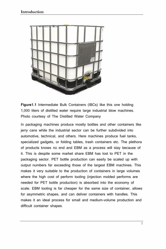
Figure1.1 Intermediate Bulk Containers (IBCs) like this one holding 1,000 liters of distilled water require large industrial blow machines. Photo courtesy of The Distilled Water Company
In packaging machines produce mostly bottles and other containers like jerry cans while the industrial sector can be further subdivided into automotive, technical, and others. Here machines produce fuel tanks, specialized gadgets, or folding tables, trash containers etc. The plethora of products knows no end and EBM as a process will stay because of it. This is despite some market share EBM has lost to PET in the packaging sector. PET bottle production can easily be scaled up with output numbers far exceeding those of the largest EBM machines. This makes it very suitable to the production of containers in large volumes where the high cost of perform tooling (injection molded performs are needed for PET bottle production) is absorbed into the economy of scale. EBM tooling is far cheaper for the same size of container, allows for asymmetric shapes, and can deliver containers with handles. This makes it an ideal process for small and medium-volume production and difficult container shapes.
Guide to Extrusion Blow Molding
3
One of the downsides of the process is that plastic protrudes out of the top and bottom of the mold. This flash must be removed from the container in some fashion, reground and put back into the material stream. This results in a more complex and potentially less predictable process, also giving rise to the possibility of contamination as dirt of all kinds may be mixed up with the regrind stream. Medical applications usually demand that only virgin resin is used for their containers but for the typical blow molded bottle this would be cost-prohibitive.
Like any other industry words have been developed to describe the particular parts of machines and process. While there is a glossary at the back I will include these special names in the text as well (in italics) so that by the time the reader has finished this book he or she should be able to converse with any expert on the subject. Unfortunately, there are different terms for the same parts and in those cases I will choose one that I find most often used.
According to the ISO (International Organization for Standardization) the units for pressure are now Pascals, for force Newtons and so on. Many people in the plastics industry are not yet familiar with these. I am therefore using the metric and standard units of bar/psi and kg/lbs instead. Academic correctness ranks less than being understood by the people that count. There is a conversion table at the end of the glossary for those who want to familiarize themselves with the new units. Another observation on the units is that some such as the distance between heads and bottle neck sizes are always metric while others can be either metric or standard. I write the dual format only in the latter cases.
This book is written in s somewhat non-linear fashion. By that I mean that for example not all troubleshooting tips are in the troubleshooting section. Instead, they are inserted in the description of machine components or material flow. This is intended to assist in memorizing the maybe not so interesting parts by connecting them with tips from the practice. I hope it works for you!

Introduction
4
Guide to Extrusion Blow Molding
5
1. Machine Types
There are basically 4 different machine types with subcategories in each type:
• Shuttle machines
• Reciprocating (“Recip”) screw machines
• Accumulator head machines
• Wheel machines
All machines have an extruder, a head that transforms the solid tube of molten plastic into a hollow parison, a clamp that carries a mold, a device to introduce air into the parison, and some way to de-mold the blown part. Other than that, machine layout and mode of operation is very different and in this section I give an overview of the various types. Chapter 2 contains more details on the main machine components while other chapters delve into other areas of interest.
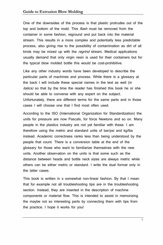
1.1 Shuttle Machines
These machines get their name from the way they shuttle one or up to four clamps mounted on a carriage between a station underneath the head and a blow station. The extruder runs continuously and sometimes the word
Figure 1.1 Layout of a double-sided shuttle machine Drawing courtesy of Graham Engineering Corporation
1. Machine Types
6
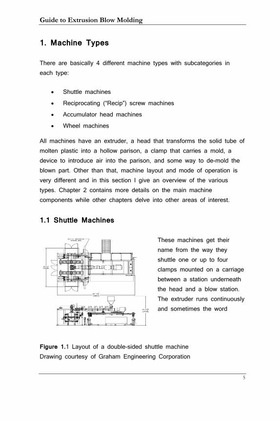
continuous is used to describe them. These machines are mostly used for bottles and deliver them with fully finished (“calibrated”) necks. When the parison is continuously extruded but part of it must be transferred to a mold a problem arises: How to prevent the two parts of the parison to stick together? There has to be a cutting device (see chapter 2.10) that separates the parison from the part that is still in the head but just moving the clamp horizontally obviously won’t do. Three solutions to this problem have emerged:
1. Blow-and-drop machines with diagonal tie-bars
2. Slanted carriage travel without tie-bars
3. Horizontal carriage travel with the extruder moving vertically
(“bobbing”) before, during and/or after cutting
1.1.1 Blow-and-Drop Machines
Figure 1.2 Blow-and-drop machine with slanted carriage travel.
Graphic courtesy of Bekum America Corporation
Guide to Extrusion Blow Molding
7
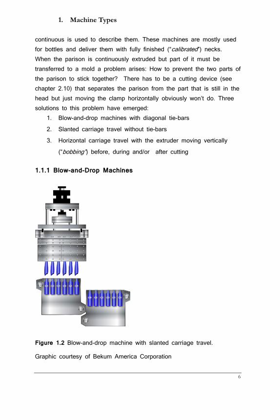
These machines represent the older technology. An interesting side-note is that they have not been produced in Europe for maybe two decades but have enjoyed great popularity in North America that is only now waning.
The carriage travels on two slanted beams in the back of the machine with the clamp overhanging in the front. The tie-bars used for mold closing are diagonally opposed in such a way that they are not in the way of the extruded parisons (see figure 1.2). In this configuration the blown bottles have to drop from the blow pins before the carriage can move up; otherwise the tie-bars would knock them off the blow pins.
Blown bottles may drop on conveyors and are then deflashed manually or one of several automatic solutions is employed. There are some that separate neck flash (“moils”) with special blow pin sleeves that grab onto them and bottom ”detabbers” that separate bottom flash inside the mold during the cycle. More common now are systems that grab bottles by their bottom flash when the mold has opened and transfer them to separate punching stations with servo-controlled electric motors.
Figure 1.3 These machines often use downstream deflashing stations
Photo courtesy of Proco Machinery
1. Machine Types
8
When the blow pins move down and engage in the mold, considerable force is extended that would normally put a strain on the bars holding the clamp in place. The solution on these older machines was to mount a double-hook assembly with one hook on the blow pin station and one at the clamp. When the mold is closed the hooks engage and any pressure exerted onto the clamp is effectively counterbalanced.
While this works quite well the assembly is always in the way when a mold change is required and many operators do not know how to properly set them (see chapter 9.6). Additionally, every four years of continuous running the tie-bar bushings of both the carriage and the clamp need to be replaced, a major maintenance expense.
The same machine set-up can also be manufactured with tie-bar less clamps. This expression is somewhat misleading: the tie-bars on these machines just sit underneath the mold area.
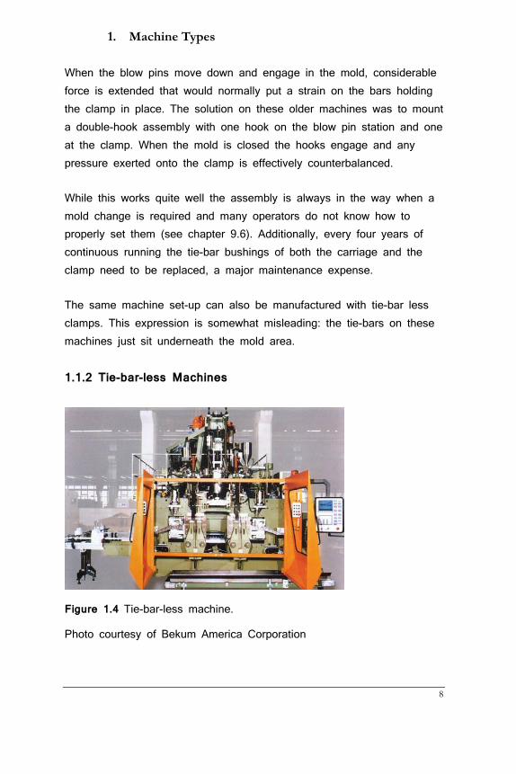
1.1.2 Tie-bar-less Machines
Figure 1.4 Tie-bar-less machine.
Photo courtesy of Bekum America Corporation

Guide to Extrusion Blow Molding
9
1. Machine Types
10
These machines use tie-bars at the bottom of the mold area. This has several advantages:
• No obstruction for blow pins or parisons, i.e. the clamp can
move up or down at any point in the cycle. Bottles do not
have to be removed from the blow pins before the clamp
moves; instead they are hanging on the blow pins until they
are taken over by a take-out/deflashing device.
• More even clamp force distribution; this is accomplished by
having an adjustment rod underneath the bars that allows for
evening out the force
• Deflash stations can be mounted onto the clamps or on a
separate device (more about that later), allowing fully deflashed
bottles to leave the machine and stay upright
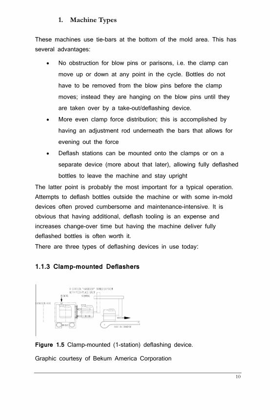
The latter point is probably the most important for a typical operation. Attempts to deflash bottles outside the machine or with some in-mold devices often proved cumbersome and maintenance-intensive. It is obvious that having additional, deflash tooling is an expense and increases change-over time but having the machine deliver fully deflashed bottles is often worth it. There are three types of deflashing devices in use today:
1.1.3 Clamp-mounted Deflashers
Figure 1.5 Clamp-mounted (1-station) deflashing device.
Graphic courtesy of Bekum America Corporation
Guide to Extrusion Blow Molding
11
Take-out masks are mounted onto the side of each clamp. When the carriage has moved up underneath the head, the mold closes and while the mold picks up another parison, the take-out masks grab the bottle that is still hanging from the blow pin. If there is only neck and bottom flash straight aluminum pieces just push the flash from the back to the front, driven by pneumatic or hydraulic cylinders in a “punch” device. If container geometry leads to flash protruding beside the neck or if there is a handle, these aluminum pieces are shaped to the contour of the bottle.
Pneumatically operated grippers grab the bottle somewhere in the center (out of the way of the punch) and move the container to a nearby conveyor. From there containers may go to a leak tester or an
automatic packer.
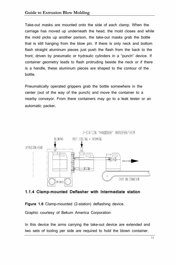
1.1.4 Clamp-mounted Deflasher with Intermediate station
Figure 1.6 Clamp-mounted (2-station) deflashing device.
Graphic courtesy of Bekum America Corporation
In this device the arms carrying the take-out device are extended and two sets of tooling per side are required to hold the blown container.
1. Machine Types
12
The second set is less complex as it just carries the already trimmed (and possibly post-cooled) container to the conveyor. When the mold opens the trimmed container stands on a rail (not shown in the graphic above) while the clamp is fetching another parison. When the mold closes the trimmed container is also grabbed by the second set of take-out tooling and then placed on the conveyor. This system works best with horizontally-moving machines (see chapter 1.3)
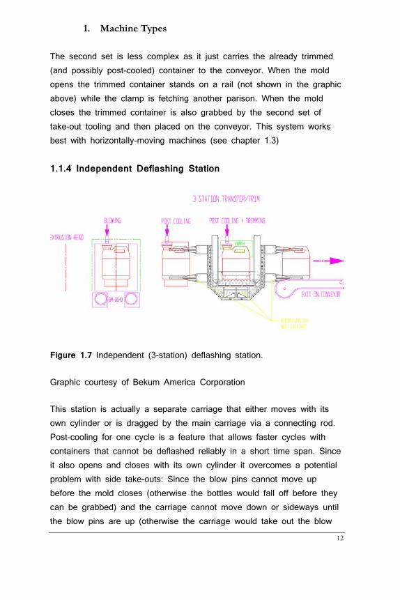
1.1.4 Independent Deflashing Station
Figure 1.7 Independent (3-station) deflashing station.
Graphic courtesy of Bekum America Corporation
This station is actually a separate carriage that either moves with its own cylinder or is dragged by the main carriage via a connecting rod. Post-cooling for one cycle is a feature that allows faster cycles with containers that cannot be deflashed reliably in a short time span. Since it also opens and closes with its own cylinder it overcomes a potential problem with side take-outs: Since the blow pins cannot move up before the mold closes (otherwise the bottles would fall off before they can be grabbed) and the carriage cannot move down or sideways until the blow pins are up (otherwise the carriage would take out the blow
Guide to Extrusion Blow Molding
13
pins), there is a possible loss of process ability. As I will explain later in more detail, the interaction of knife cutting and carriage down or sideways movement are paramount to getting an open parison, which is important to avoid material push-ins into the neck. The dependence of the carriage down or sideways movement on the blow pin (instead of the carriage down timer alone) may hamper the operator’s ability to find the optimal settings. This is not the case with the 3-station deflash device as it closes before the mold and the blow pin can move up while the mold is closing.
A significant disadvantage of this device is that it enlarges the footprint of the machine significantly in the important direction. With that I mean that machines in a plant are usually set with the fronts of the machines side by side. Long front dimensions therefore mean fewer machines in a given space, an issue that has hampered the wide-spread use of this otherwise very useful device.
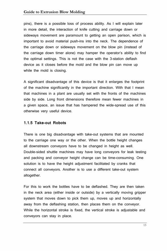
1.1.5 Take-out Robots
There is one big disadvantage with take-out systems that are mounted to the carriage one way or the other. When the bottle height changes all downstream conveyors have to be changed in height as well. Double-sided shuttle machines may have long conveyors for leak testing and packing and conveyor height change can be time-consuming. One solution is to have the height adjustment facilitated by cranks that connect all conveyors. Another is to use a different take-out system altogether.
For this to work the bottles have to be deflashed. They are then taken in the neck area (either inside or outside) by a vertically moving gripper system that moves down to pick them up, moves up and horizontally away from the deflashing station, then places them on the conveyor. While the horizontal stroke is fixed, the vertical stroke is adjustable and conveyors can stay in place.
1. Machine Types
14
Figure 1.9 Take-out robot
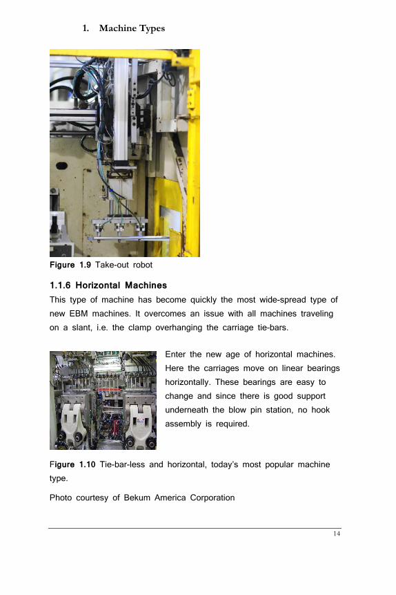
1.1.6 Horizontal Machines This type of machine has become quickly the most wide-spread type of new EBM machines. It overcomes an issue with all machines traveling on a slant, i.e. the clamp overhanging the carriage tie-bars.
Enter the new age of horizontal machines. Here the carriages move on linear bearings horizontally. These bearings are easy to change and since there is good support underneath the blow pin station, no hook assembly is required.
Figure 1.10 Tie-bar-less and horizontal, today’s most popular machine type.
Photo courtesy of Bekum America Corporation

Guide to Extrusion Blow Molding
15
1. Machine Types
16
As mentioned before, in order to prevent the continuously extruded parison to stick to the freshly cut one the extruder has to move up (“bob”) during cutting. This makes it necessary to set the entire extruder assembly on a pivot using a hydraulic cylinder to effect the movement. The additional cost of this setup should not be underestimated and is one reason why these machines are more expensive than the ones made with fixed extruders.
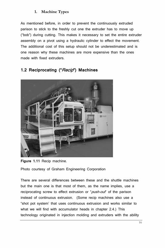
1.2 Reciprocating (“Recip”) Machines
Figure 1.11 Recip machine.
Photo courtesy of Graham Engineering Corporation
There are several differences between these and the shuttle machines but the main one is that most of them, as the name implies, use a reciprocating screw to effect extrusion or “push-out” of the parison instead of continuous extrusion. (Some recip machines also use a “shot pot system’ that uses continuous extrusion and works similar to what we will find with accumulator heads in chapter 2.4.) This technology originated in injection molding and extruders with the ability
Guide to Extrusion Blow Molding
17
for push-out are very common. With this machine type a new problem arises: If the mold is not moving then how can a blow pin enter the mold and blow the part? On most machines the blow pin is inside the head and moves down on a separate cylinder (“ram”) when the mold has closed. This allows the in-mold calibration (see Introduction) of the bottle. The flash however must be removed in a secondary punch station. In order to keep the containers oriented a very unique take-out device has been invented. Grippers grab the bottles by their bottom flash after the mold has opened but unlike in blow-and-drop machines the grippers are mechanically linked to the mold movement, an elegant solution with little maintenance requirements. Recip machines are typically used in the production of very lightweight milk bottles and 4 and 2 liter (gallon and half gallon in North America) round containers with handles. They are very efficient and produce these containers rivaling the volume to container weight ratio that we usually expect from PET bottles. Additionally, they provide handles which cannot be molded in PET bottles.
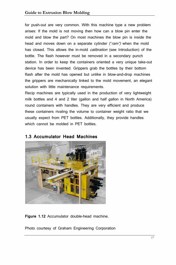
1.3 Accumulator Head Machines
Figure 1.12 Accumulator double-head machine.
Photo courtesy of Graham Engineering Corporation
1. Machine Types
18
There comes a point when it becomes too energy-intensive and costly to move the carriage in a shuttle machine. Typically used on container sizes over 20 l these machines have a stationary platen and extrusion head. Instead of using a reciprocating screw the extruder may run continuous or intermittent but the material is stored inside the accumulator head. We will examine the accumulator head design in chapter 2 but needless to say that they do need a device to push out the parison when the mold is ready. This device is also called a ram. Parts removal is sometimes done manually but like many machines today the system above has a take-out robot that uses a top-flash gripper to hold on to the part and moving it out of the molding area. Parts are then deflashed manually or with a separate punch device.
Guide to Extrusion Blow Molding
19
To introduce blow air into the parison accumulator head machines use either blow pins mounted at the bottom of the mold or blow needles.
The latter are retracted during mold closing and move forward after a timer has timed out. They pierce the parison and leave a small hole in the finished container.
The type of container made on these machines ranges from automotive bumpers and fuel tanks, jerry cans of all sizes, tables and chairs to 55 gal drums and IBCs. Besides standard materials they also use just about any engineering resin that is blow moldable. Nylon, ABS, PC… the list goes on and on. Co-extrusion (see chapter 7) has also expanded the range of products that can be molded on these machines.
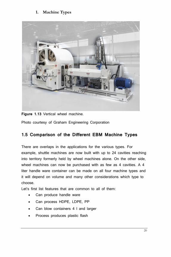
1.4 Wheel Machines These machines are typically used for very high volumes. Up to 30 clamps are mounted on a vertical or horizontal wheel that continuously turns. The extruded parison may be placed into the molds from the bottom or top in single or dual cavity. To further increase output 2 bottles can be blown in the same cavity neck to neck. Blow air is introduced via a needle in a part of the parison that does not form the bottle and all flash is trimmed off in a separate station. High-cavity machines of this type plus associated conveyors and punch devices may become very costly and a commitment to high volumes is certainly necessary to justify them. The continuous process compared to the intermittent one on all other EBM machines runs more consistently yielding high pack-out rates. The machines are somewhat harder to start up, though and require more experienced personnel
1. Machine Types
20
Figure 1.13 Vertical wheel machine.
Photo courtesy of Graham Engineering Corporation
1.5 Comparison of the Different EBM Machine Types
There are overlaps in the applications for the various types. For example, shuttle machines are now built with up to 24 cavities reaching into territory formerly held by wheel machines alone. On the other side, wheel machines can now be purchased with as few as 4 cavities. A 4 liter handle ware container can be made on all four machine types and it will depend on volume and many other considerations which type to choose. Let’s first list features that are common to all of them:
• Can produce handle ware
• Can process HDPE, LDPE, PP
• Can blow containers 4 l and larger
• Process produces plastic flash
Guide to Extrusion Blow Molding
21
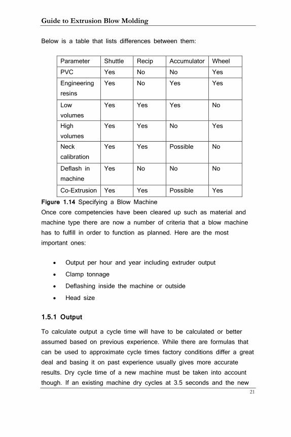
Below is a table that lists differences between them:
Parameter Shuttle Recip Accumulator Wheel PVC Yes No No Yes Engineering resins
Yes No Yes Yes
Low volumes
Yes Yes Yes No
High volumes
Yes Yes No Yes
Neck calibration
Yes Yes Possible No
Deflash in machine
Yes No No No
Co-Extrusion Yes Yes Possible Yes
Figure 1.14 Specifying a Blow Machine Once core competencies have been cleared up such as material and machine type there are now a number of criteria that a blow machine has to fulfill in order to function as planned. Here are the most important ones:
• Output per hour and year including extruder output
• Clamp tonnage
• Deflashing inside the machine or outside
• Head size
1.5.1 Output
To calculate output a cycle time will have to be calculated or better assumed based on previous experience. While there are formulas that can be used to approximate cycle times factory conditions differ a great deal and basing it on past experience usually gives more accurate results. Dry cycle time of a new machine must be taken into account though. If an existing machine dry cycles at 3.5 seconds and the new
1. Machine Types
22
machine runs at 2.8 seconds, then the new cycle time should be 0.7 seconds shorter.
Output considerations are typically based on yearly requirements. Production hours per year and estimated utilization percentage come into play here as well. Utilization is not only determined by frequency of change-overs or maintenance downtime but also by changing demand requirements that may vary by season or other events. Drinks manufacturers are busier in the summer time while other companies have their highest demand going into the Christmas season. Utilization rates of more than 80% are often not achievable in a typical converter plant. At 80% this lowers the number of hours per year a machine in a 24/7 production environment can run from 8,400 to 6,720. Take away two weeks or so for statuary holidays plus maintenance time and a reasonable number may be 6,500 running hours per year. For new machines an up-time rate or productivity factor of 96% may be assumed, for older machines this may be as low as 90% and needs to be factored in as well. If the container can run in single cavity then the output calculation is finished. However, in multi-cavity molds the horizontal space on the platen must be chosen to fit all cavities leaving at minimum of 10 mm (better 15 to 20 mm) between them. The number of cavities can be determined by calculating the number of containers that can be produced in an hour in single cavity given the assumed cycle time and dividing that number in the required output per hour.
1.5.2 Tonnage Based on the demand requirements and the number of available hours per year the output per hour can now be calculated. Next the required clamp tonnage should be calculated. This is done two ways:
• The clamp force has to be stronger than the force exerted by
the air pressure times the projected area of the container(s)
• The clamp has to be strong enough to cut all protruding flash
Guide to Extrusion Blow Molding
23
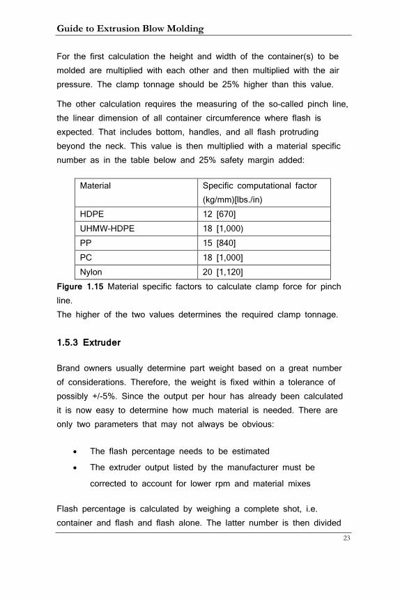
For the first calculation the height and width of the container(s) to be molded are multiplied with each other and then multiplied with the air pressure. The clamp tonnage should be 25% higher than this value.
The other calculation requires the measuring of the so-called pinch line, the linear dimension of all container circumference where flash is expected. That includes bottom, handles, and all flash protruding beyond the neck. This value is then multiplied with a material specific number as in the table below and 25% safety margin added:
Material Specific computational factor (kg/mm)[lbs./in)
HDPE 12 [670] UHMW-HDPE 18 [1,000) PP 15 [840] PC 18 [1,000] Nylon 20 [1,120]
Figure 1.15 Material specific factors to calculate clamp force for pinch line. The higher of the two values determines the required clamp tonnage.
1.5.3 Extruder
Brand owners usually determine part weight based on a great number of considerations. Therefore, the weight is fixed within a tolerance of possibly +/-5%. Since the output per hour has already been calculated it is now easy to determine how much material is needed. There are only two parameters that may not always be obvious:
• The flash percentage needs to be estimated
• The extruder output listed by the manufacturer must be
corrected to account for lower rpm and material mixes
Flash percentage is calculated by weighing a complete shot, i.e. container and flash and flash alone. The latter number is then divided
1. Machine Types
24
into the former and multiplied by 100. Here are some thumb-rule numbers for 4 types of bottles:
• Bottle with parison staying inside neck: 25%
• Bottle with flash protruding beyond neck: 35%
• Bottle with handle: 45%
• Fully flashed container: >50%
All manufacturers list the maximum extruder output usually for virgin PE at maximum rpm. It is not realistic to run that way and therefore this number should be reduced by 15%. Depending on the type of screw extruder output will decrease with an increase in regrind percentage. Taking another 5% off the listed number should be considered unless the used screw is independent of regrind percentage.
1.5.4 Die Diameter
This parameter is important as each extrusion head has a maximum die diameter that should not be exceeded. The parison diameter can be calculated by measuring the pinch line at the bottom, whether this is at an actual container or a drawing. This line is actually half the circumference of the parison diameter because the parison is being collapsed by the mold. Because the parison swells in most cases (see chapter 6) the die diameter must be estimated based on previous experience with the material that is to be used.
1.5.6 An Example
Let’s assume yearly requirements are 6 million bottles. Part weight is 125 g, material is HDPE with 3% color. Based on 6,500 hours/year hourly output is
6,000,000/6,500 = 923 containers/hour
Guide to Extrusion Blow Molding
25
The project requires a new machine and one therefore assumes 96% productivity. This results in a higher number of bottles needed:
923 / 0.96 ~ 960 containers/hour
Based on previous experience a cycle time of 18 seconds is assumed. This means one cavity can produce this many containers/hour:
3,600 s/hour / 15 s/container = 240 containers/hour
Since 960 c/h are required the number of cavities is
960 c/h / 240 c/h/cavity = 4 cavities
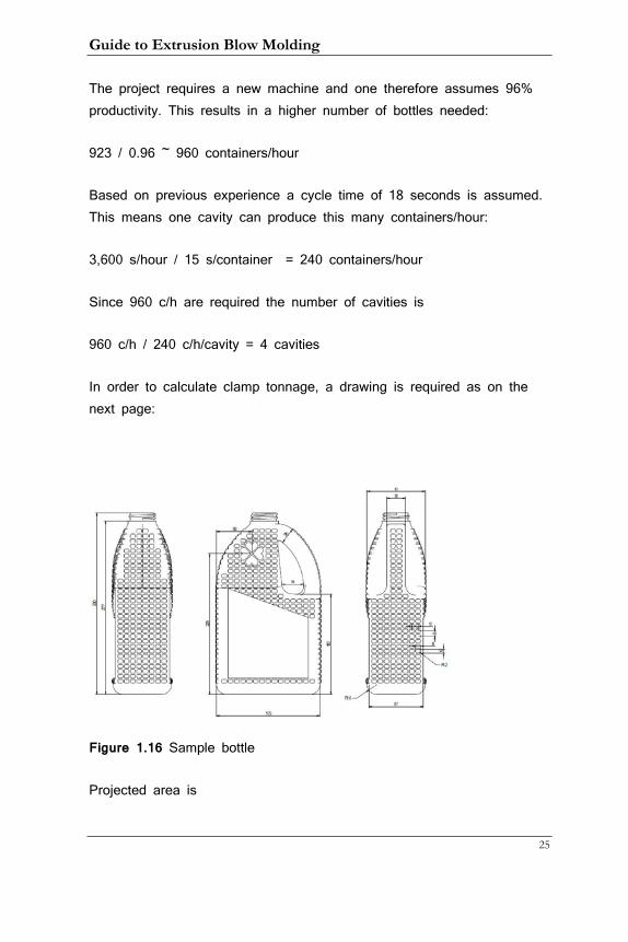
In order to calculate clamp tonnage, a drawing is required as on the next page:
Figure 1.16 Sample bottle
Projected area is
1. Machine Types
26
290 mm x 165 mm = 47,850 mm2 or 478 cm2
This is not totally correct as the shoulder area is counted more than is required but for our purpose here it should suffice. Tonnage at 10 bar (kg/cm2) maximum blow pressure is
478 cm2 x 10 kg/cm2 = 4,780 kg per container or 4.8 tons
Adding 25% will result in
4.8 ton * 1.25 = 6 tons per container
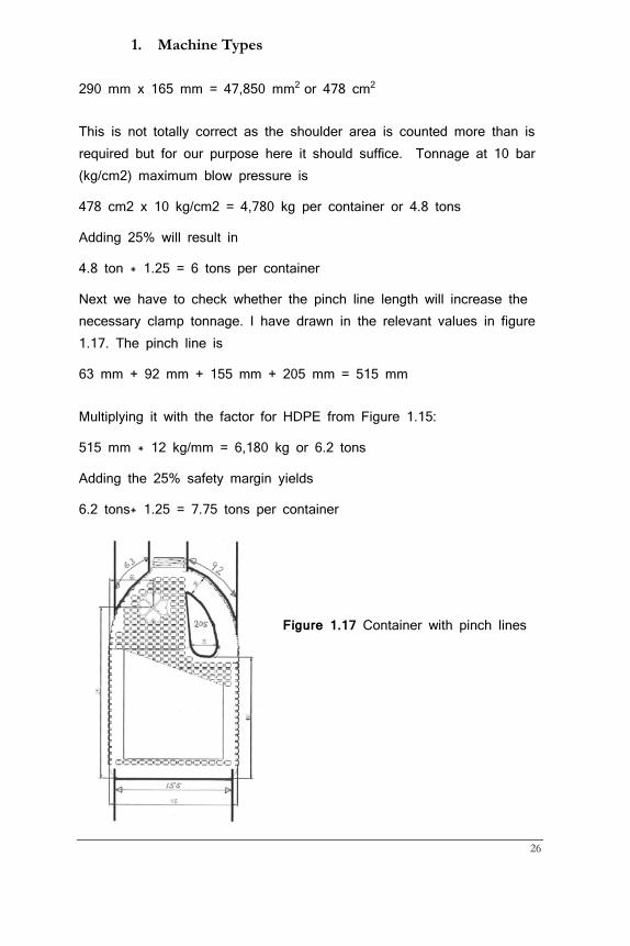
Next we have to check whether the pinch line length will increase the necessary clamp tonnage. I have drawn in the relevant values in figure 1.17. The pinch line is
63 mm + 92 mm + 155 mm + 205 mm = 515 mm
Multiplying it with the factor for HDPE from Figure 1.15:
515 mm * 12 kg/mm = 6,180 kg or 6.2 tons
Adding the 25% safety margin yields
6.2 tons* 1.25 = 7.75 tons per container
Figure 1.17 Container with pinch lines

Guide to Extrusion Blow Molding
27
In a dual-cavity setup clamp tonnage should therefore be about 15 tons.
At this point the choice is between a 4-station wheel machine with 8 tons of clamp tonnage or a dual-shuttle machine with 2 cavities on each side and a clamp tonnage of 15 tons or a recip machine with 4 cavities and a clamp tonnage of 30 tons. For the shuttle machine the physical size of the platen must be considered. Postulating 15 mm between cavities and 20 mm on either end of the mold the horizontal minimum dimension is
2 * 165 mm + 1 * 15 mm + 2 x 20 mm = 385 mm
For the recip machine it would be
4 * 165 mm + 3 * 15 mm + 2 * 20 mm = 745 mm
It should be noted that molds can overhang by up to 25 mm on some machines but for handle-ware this is not recommended. The distance between heads is 165 mm + 15 mm = 180 mm so a dual 180 mm head would be required for the shuttle machine and a quad 180 mm for the recip one. There may be no head with that exact center distance and one would have to choose the next size up.
Assuming a 45% flash percentage the total shot weight with 4 cavities is
125 g * 4 cavities * / (1 - 0.45) = 909 g
Using 15 seconds cycle time the required hourly output is
3,600 s/hour / 15 s * 909 g = 218,160g/h or 218 kg/h [480 lbs./h]
Taking 20% off the listed output number to account for lower rpm and the possible effect of regrind we get
1. Machine Types
28
218 kg/h / (1 – 0.2) = 273kg/h [600 lbs./h]
This is the value to compare the data to that given by manufacturers.
To calculate the die size we have to start with the bottom pinch line that is 155 mm. This can be imagined as half of the circumference of the parison. The formula for circumference is diameter * PI. The diameter of the parison with a pinch line of 155 mm is therefore
2 * 155 mm / 3.14 = 99 mm
Chapter 6 explains that the parison swells after it leaves the die and the values given for HDPE are 15% To 40%. Using 25% for swell we get a die diameter of
99 mm / 1.25 = 79 mm
Therefore, the head should allow for a minimum die diameter of 80 mm. 100 mm would be better as the swell could be less when diverging tooling is used.
Guide to Extrusion Blow Molding
29
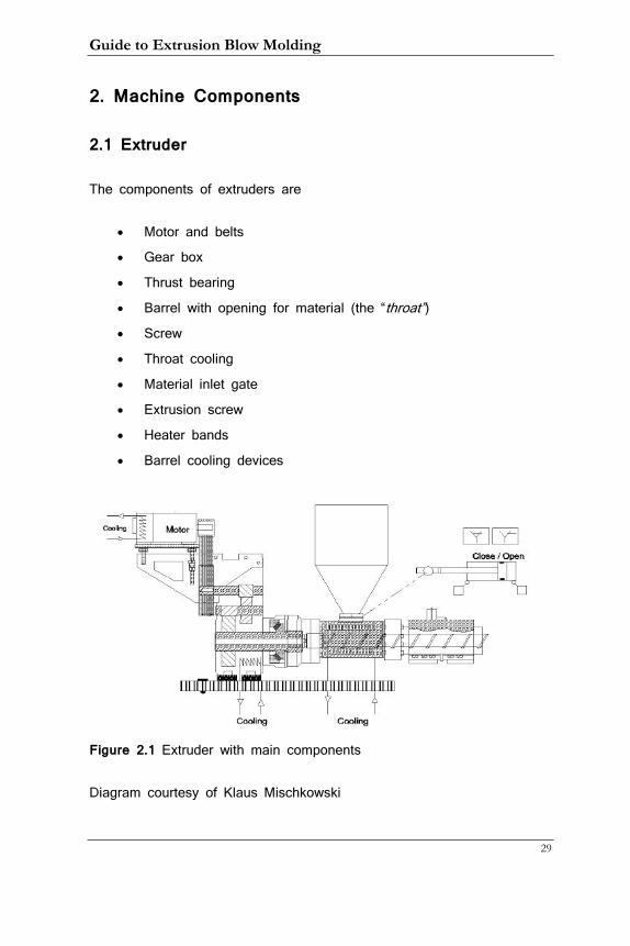
2. Machine Components
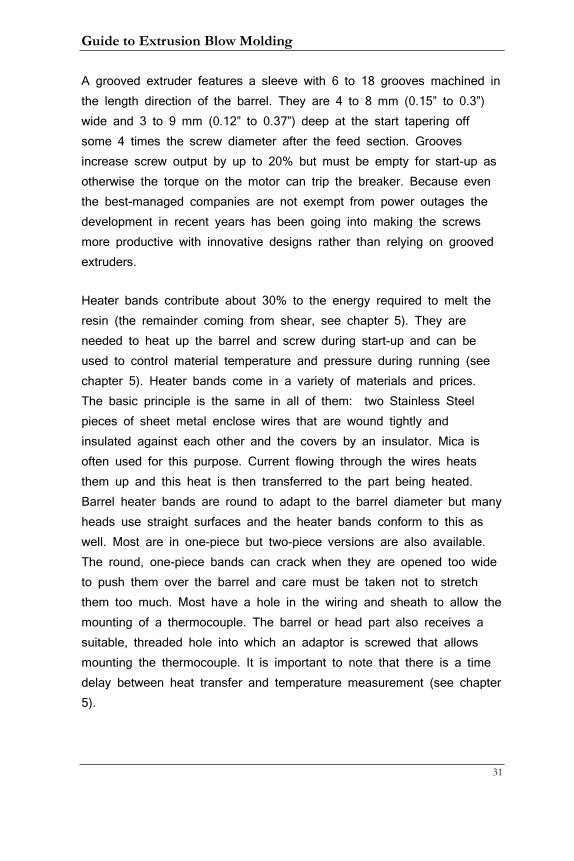
2.1 Extruder
The components of extruders are
• Motor and belts
• Gear box
• Thrust bearing
• Barrel with opening for material (the “throat”) • Screw
• Throat cooling
• Material inlet gate
• Extrusion screw
• Heater bands
• Barrel cooling devices
Figure 2.1 Extruder with main components
Diagram courtesy of Klaus Mischkowski
2. Machine Components
30
Modern machines use brushless AC motors that are the most energy-efficient ones, need little maintenance and have good torque in the lower rpm range. Historically, machines used hydraulic motors, DC motors with brushes and brushless DC motors. Hydraulic motors have the advantage that no gear box is needed but they are notorious energy wasters especially when they run continuously at low rpm. The initial DC motors required maintenance to change the brushes every so often while newer motors, whether AC or DC do not.
As the screw is turned there is a considerable force pushing backwards as the material is moving forward and a relatively large thrust bearing is needed to counteract this force. To replace it the barrel has to be removed, a time-intensive task. It is therefore advisable to select an extruder large enough so it can be run at a lower than maximum rpm. Higher rpms stress this bearing significantly.
The barrel itself is most often nitrided to a depth of 0.5 to 1 mm and hardened to around 70 HRc while screws are most often not harder than 65 HRc so that the screw wears out first.
The barrel throat that houses the end of the screw and the material inlet must be water-cooled. This is to prevent material from melting in the feed zone (see chapter 5). Water-tower water up to 30° C (86°F) can be used as this area should be hand-warm to prevent condensation. If only chiller water is available, flow should be reduced.
A manually or pneumatically operated slide gate separates resin in the hopper from the extruder throat. It is always a good idea to run the extruder empty before shutting the machine off even though some materials like HDPE can be left in the extruder without causing any damage. This is not the case with other materials such as PVC (see chapter 4) and even with HDPE when a grooved extruder is used.
Guide to Extrusion Blow Molding
31
A grooved extruder features a sleeve with 6 to 18 grooves machined in the length direction of the barrel. They are 4 to 8 mm (0.15” to 0.3”) wide and 3 to 9 mm (0.12” to 0.37”) deep at the start tapering off some 4 times the screw diameter after the feed section. Grooves increase screw output by up to 20% but must be empty for start-up as otherwise the torque on the motor can trip the breaker. Because even the best-managed companies are not exempt from power outages the development in recent years has been going into making the screws more productive with innovative designs rather than relying on grooved extruders.
Heater bands contribute about 30% to the energy required to melt the resin (the remainder coming from shear, see chapter 5). They are needed to heat up the barrel and screw during start-up and can be used to control material temperature and pressure during running (see chapter 5). Heater bands come in a variety of materials and prices. The basic principle is the same in all of them: two Stainless Steel pieces of sheet metal enclose wires that are wound tightly and insulated against each other and the covers by an insulator. Mica is often used for this purpose. Current flowing through the wires heats them up and this heat is then transferred to the part being heated. Barrel heater bands are round to adapt to the barrel diameter but many heads use straight surfaces and the heater bands conform to this as well. Most are in one-piece but two-piece versions are also available. The round, one-piece bands can crack when they are opened too wide to push them over the barrel and care must be taken not to stretch them too much. Most have a hole in the wiring and sheath to allow the mounting of a thermocouple. The barrel or head part also receives a suitable, threaded hole into which an adaptor is screwed that allows mounting the thermocouple. It is important to note that there is a time delay between heat transfer and temperature measurement (see chapter 5).
2. Machine Components
32
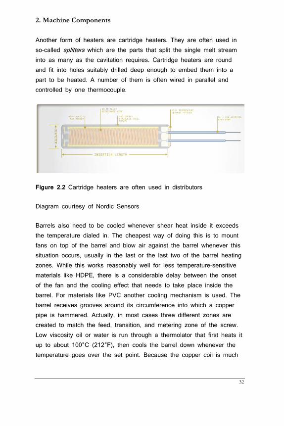
Another form of heaters are cartridge heaters. They are often used in so-called splitters which are the parts that split the single melt stream into as many as the cavitation requires. Cartridge heaters are round and fit into holes suitably drilled deep enough to embed them into a part to be heated. A number of them is often wired in parallel and controlled by one thermocouple.
Figure 2.2 Cartridge heaters are often used in distributors
Diagram courtesy of Nordic Sensors
Barrels also need to be cooled whenever shear heat inside it exceeds the temperature dialed in. The cheapest way of doing this is to mount fans on top of the barrel and blow air against the barrel whenever this situation occurs, usually in the last or the last two of the barrel heating zones. While this works reasonably well for less temperature-sensitive materials like HDPE, there is a considerable delay between the onset of the fan and the cooling effect that needs to take place inside the barrel. For materials like PVC another cooling mechanism is used. The barrel receives grooves around its circumference into which a copper pipe is hammered. Actually, in most cases three different zones are created to match the feed, transition, and metering zone of the screw. Low viscosity oil or water is run through a thermolator that first heats it up to about 100°C (212°F), then cools the barrel down whenever the temperature goes over the set point. Because the copper coil is much
Guide to Extrusion Blow Molding
33
closer to the shear heat in the barrel and the liquid can cool much quicker than air, this type of cooling system is very effective.
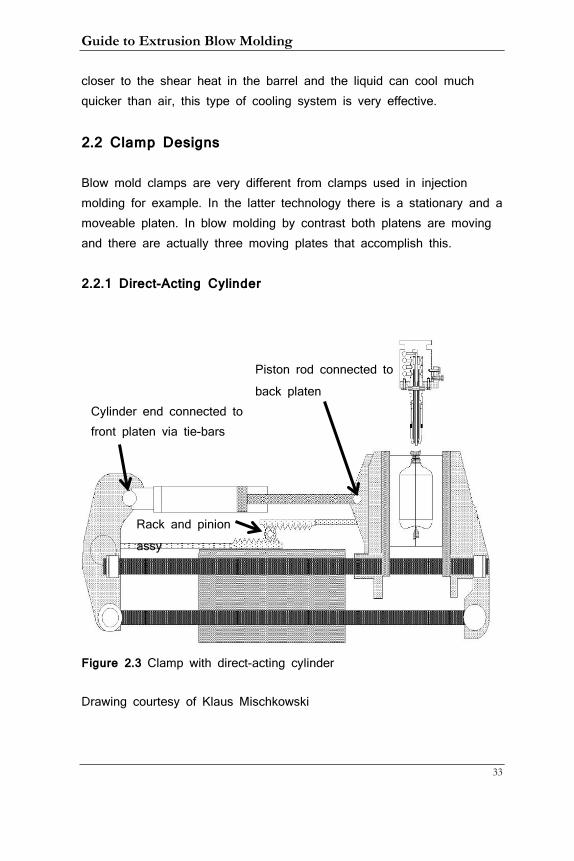
2.2 Clamp Designs
Blow mold clamps are very different from clamps used in injection molding for example. In the latter technology there is a stationary and a moveable platen. In blow molding by contrast both platens are moving and there are actually three moving plates that accomplish this.
2.2.1 Direct-Acting Cylinder
Figure 2.3 Clamp with direct-acting cylinder
Drawing courtesy of Klaus Mischkowski
Rack and pinion assy
Cylinder end connected to front platen via tie-bars
Piston rod connected to back platen
2. Machine Components
34
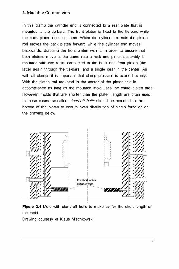
In this clamp the cylinder end is connected to a rear plate that is mounted to the tie-bars. The front platen is fixed to the tie-bars while the back platen rides on them. When the cylinder extends the piston rod moves the back platen forward while the cylinder end moves backwards, dragging the front platen with it. In order to ensure that both platens move at the same rate a rack and pinion assembly is mounted with two racks connected to the back and front platen (the latter again through the tie-bars) and a single gear in the center. As with all clamps it is important that clamp pressure is exerted evenly. With the piston rod mounted in the center of the platen this is accomplished as long as the mounted mold uses the entire platen area. However, molds that are shorter than the platen length are often used. In these cases, so-called stand-off bolts should be mounted to the bottom of the platen to ensure even distribution of clamp force as on the drawing below.
Figure 2.4 Mold with stand-off bolts to make up for the short length of the mold Drawing courtesy of Klaus Mischkowski
Guide to Extrusion Blow Molding
35
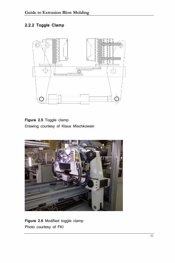
2.2.2 Toggle Clamp
Figure 2.5 Toggle clamp Drawing courtesy of Klaus Mischkowski
Figure 2.6 Modified toggle clamp Photo courtesy of FKI
2. Machine Components
36
While this clamp does not fit exactly the toggle systems that are in use at injection molding machines they have become quite popular and are usually referred to as toggle blow mold clamps. They are more compact as they are occupying space beneath the clamp that is otherwise not used. They also use only two plates without any tie-bars. Instead, molds move on linear bearings that also have become very popular because of their long life and easy replacement compared to tie-bars.
The cylinder rod is connected to the front arm while the cylinder is fastened to the back arm. Several devices are in use to ensure that the two arms move at the same rate. The location of the pivot point determines the clamp stroke and tonnage. Because of the space constraints the pivot point usually sits in the center of the toggle arm. That means that cylinder and clamp stroke are the same and the force the cylinder can extend is the clamp tonnage. Other scenarios are possible but seldom used.
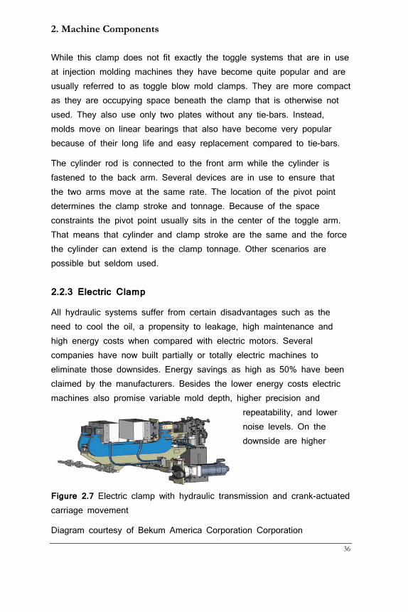
2.2.3 Electric Clamp
All hydraulic systems suffer from certain disadvantages such as the need to cool the oil, a propensity to leakage, high maintenance and high energy costs when compared with electric motors. Several companies have now built partially or totally electric machines to eliminate those downsides. Energy savings as high as 50% have been claimed by the manufacturers. Besides the lower energy costs electric machines also promise variable mold depth, higher precision and
repeatability, and lower noise levels. On the downside are higher
Figure 2.7 Electric clamp with hydraulic transmission and crank-actuated carriage movement
Diagram courtesy of Bekum America Corporation Corporation

Guide to Extrusion Blow Molding
37
prices and somewhat more complex controls that are not as easily repaired as hydraulic systems. A combination of higher energy costs and lower production costs will have electric drives eventually win out but we are not there yet.
2.3 Blow Pins
On a shuttle machine the blow pin has three functions:
• Introduce air into the parison
• Calibrate the neck
• Cool the neck area
Blow air is introduced through a center pipe that may or may not be proud of the blow pin end. The pneumatic valve controlling blow air may be situated somewhere in a cabinet or close by. In either case the air does not travel back through the valve as this would slow down the decompression of the blown container. Instead, a quick exhaust valve is mounted close to the blow pin(s) that uses a moveable membrane to give air access to the environment right at the valve as soon as the blow air valve is switched from blow to idle.
It is paramount that blow pins are always water-cooled since the neck section is often the thickest part of the container. Blow pins consist of two parts: the body and the tip. In most cases water just cools the body but when the neck becomes very thick (>2 mm), it may be worth it to also cool the tip. This makes for a more complex blow pin construction but will pay off if neck cooling holds up the cycle (which is
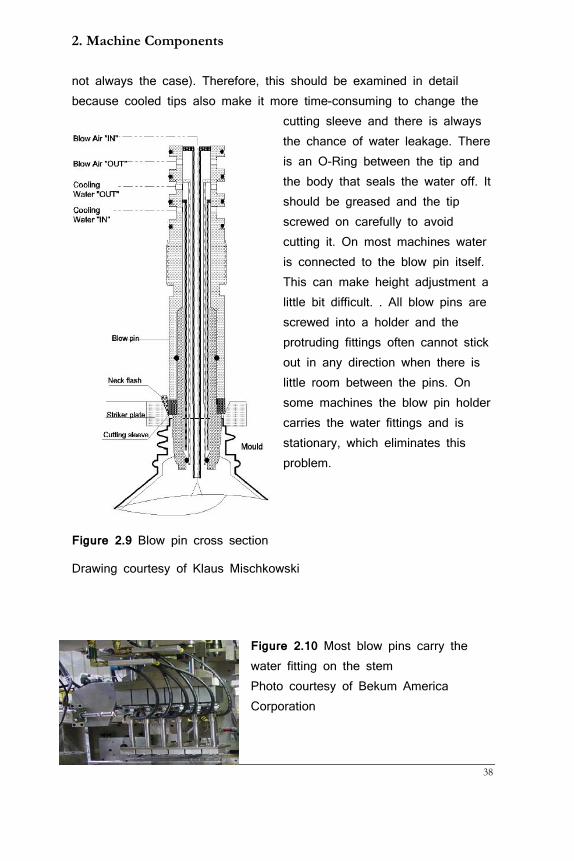
2. Machine Components
38
not always the case). Therefore, this should be examined in detail because cooled tips also make it more time-consuming to change the
cutting sleeve and there is always the chance of water leakage. There is an O-Ring between the tip and the body that seals the water off. It should be greased and the tip screwed on carefully to avoid cutting it. On most machines water is connected to the blow pin itself. This can make height adjustment a little bit difficult. . All blow pins are screwed into a holder and the protruding fittings often cannot stick out in any direction when there is little room between the pins. On some machines the blow pin holder carries the water fittings and is stationary, which eliminates this problem.
Figure 2.9 Blow pin cross section
Drawing courtesy of Klaus Mischkowski
Figure 2.10 Most blow pins carry the water fitting on the stem Photo courtesy of Bekum America Corporation
Guide to Extrusion Blow Molding
39
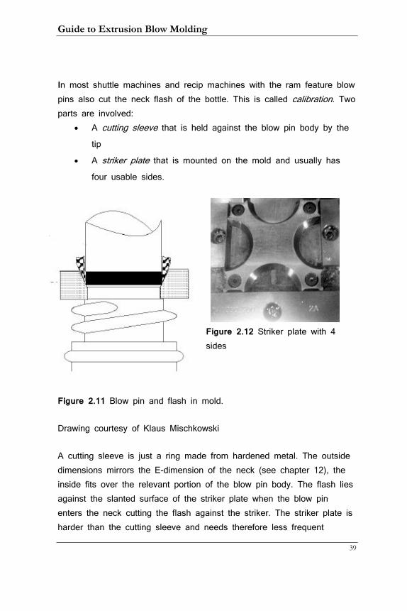
In most shuttle machines and recip machines with the ram feature blow pins also cut the neck flash of the bottle. This is called calibration. Two parts are involved:
• A cutting sleeve that is held against the blow pin body by the tip
• A striker plate that is mounted on the mold and usually has
four usable sides.
Figure 2.12 Striker plate with 4 sides
Figure 2.11 Blow pin and flash in mold.
Drawing courtesy of Klaus Mischkowski
A cutting sleeve is just a ring made from hardened metal. The outside dimensions mirrors the E-dimension of the neck (see chapter 12), the inside fits over the relevant portion of the blow pin body. The flash lies against the slanted surface of the striker plate when the blow pin enters the neck cutting the flash against the striker. The striker plate is harder than the cutting sleeve and needs therefore less frequent
2. Machine Components
40
changing. For the neck to be round and straight a number of conditions must exist:
• The blow pin must be centered to the neck in the mold
• The blow pin must be straight
• The cutting sleeve must be sharp
• The striker plate must be without chafes
• The flash must be open to receive the blow pin to avoid
material being pushed into the neck by the descending pin
• The blow pin must be cold enough and the cooling time
sufficient to allow enough neck cooling so the neck won’t
distort after de-molding (more on that in chapter 10)
It is a time-consuming task to center all blow pins in a multi-cavity setup but it worthwhile doing. In chapter 9 is a procedure for it.
2.4 Cutting Devices
These devices are all for shuttle machines as the parison is not cut in the other machine types. Cuts from all types of knives are the most or second-most (after burns) causes of injuries on blow molding machines. They have to be extremely sharp to work properly and operators must take extra caution when working around them. They should be covered with appropriate leather or metal sheaths when operators make adjustments in their proximity!
2.4.1 Swing knife
This was at one time the most widely used type of knife but has since fallen out of favor as other devices proved to be more suitable. It is seldom used with more than 2 cavities. The knife is shaped like a spear head but cuts the parison with wither side, i.e. with a flat edge. For this to work it has to be very sharp and move at high speed. Typically it is mounted to a rack and pinion assembly whereby a linear,
Guide to Extrusion Blow Molding
41
pneumatic cylinder pushes the rack and the pinion moves the knife from one side to the other.
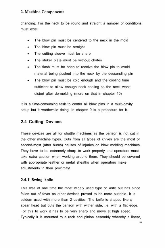
The disadvantage of this knife is that the flat entry into the parison often leads to the latter not cutting cleanly or falling in, which causes problems with push-ins. The drawing on the left shows a modified swing knife. It has been shaped in such a way that the tip protruding from the side pierces the parison at a point rather than a straight edge greatly improving its effectiveness.
Figure 2.13 Modified swing knife with piercing edge
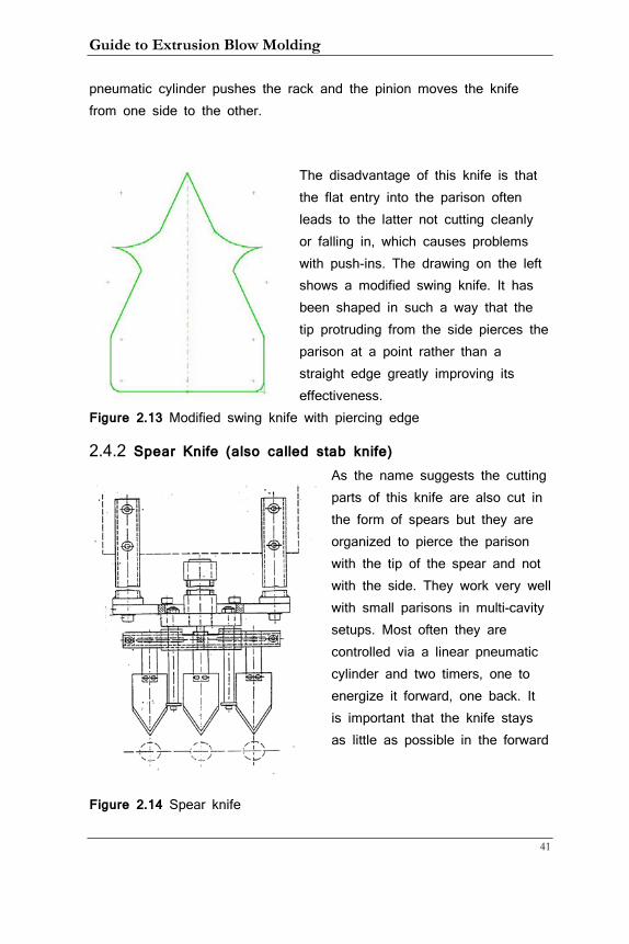
2.4.2 Spear Knife (also called stab knife) As the name suggests the cutting parts of this knife are also cut in the form of spears but they are organized to pierce the parison with the tip of the spear and not with the side. They work very well with small parisons in multi-cavity setups. Most often they are controlled via a linear pneumatic cylinder and two timers, one to energize it forward, one back. It is important that the knife stays as little as possible in the forward
Figure 2.14 Spear knife
2. Machine Components
42
position under the head and the quick exhaust valve described in the blow pin section allows a quick change of direction and is highly recommended here as well. An excellent way of moving this knife is with an electric motor and a crank. One turn of the motor moves the knife back and forth in one smooth motion without any stopping.
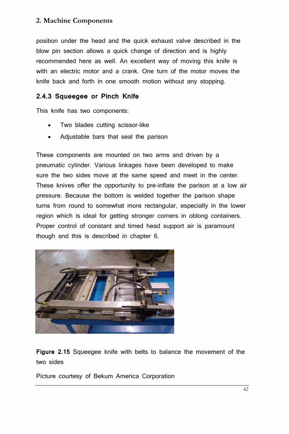
2.4.3 Squeegee or Pinch Knife
This knife has two components:
• Two blades cutting scissor-like
• Adjustable bars that seal the parison
These components are mounted on two arms and driven by a pneumatic cylinder. Various linkages have been developed to make sure the two sides move at the same speed and meet in the center. These knives offer the opportunity to pre-inflate the parison at a low air pressure. Because the bottom is welded together the parison shape turns from round to somewhat more rectangular, especially in the lower region which is ideal for getting stronger corners in oblong containers. Proper control of constant and timed head support air is paramount though and this is described in chapter 6.
Figure 2.15 Squeegee knife with belts to balance the movement of the two sides
Picture courtesy of Bekum America Corporation
Guide to Extrusion Blow Molding
43
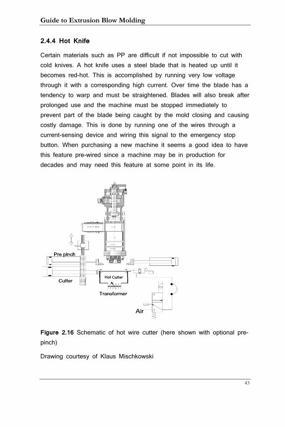
2.4.4 Hot Knife
Certain materials such as PP are difficult if not impossible to cut with cold knives. A hot knife uses a steel blade that is heated up until it becomes red-hot. This is accomplished by running very low voltage through it with a corresponding high current. Over time the blade has a tendency to warp and must be straightened. Blades will also break after prolonged use and the machine must be stopped immediately to prevent part of the blade being caught by the mold closing and causing costly damage. This is done by running one of the wires through a current-sensing device and wiring this signal to the emergency stop button. When purchasing a new machine it seems a good idea to have this feature pre-wired since a machine may be in production for decades and may need this feature at some point in its life.
Figure 2.16 Schematic of hot wire cutter (here shown with optional pre-pinch)
Drawing courtesy of Klaus Mischkowski
2. Machine Components
44
2.4.5 Specialty Knife
There is one more knife that deserves mentioning. It is used whenever a standard cutter will not work but a hot knife could cause burning of the material. This knife is a squeegee knife but instead of the two blades set underneath the squeegee bars it contains a standard spear knife moved by a piston-less cylinder.
Because the knife cuts with its flat side it must be kept very sharp. I have run co-polyester with good success with this knife configuration.
2.5 Head Technologies
The head, extrusion head or die head changes the direction of the melt flow from horizontal to vertical and converts the solid stream into a hollow parison. There are two general types of heads:
• The side-fed, radial , mandrel, or pinole head
• The center-fed, axial, torpedo or spider head
I am including all the names that are used in the industry to facilitate recognition.
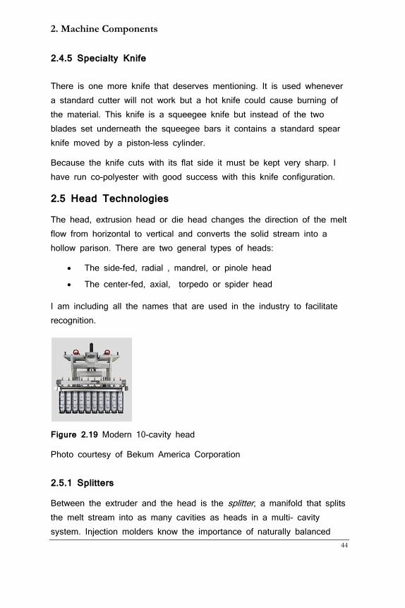
Figure 2.19 Modern 10-cavity head
Photo courtesy of Bekum America Corporation
2.5.1 Splitters
Between the extruder and the head is the splitter, a manifold that splits the melt stream into as many cavities as heads in a multi- cavity system. Injection molders know the importance of naturally balanced
Guide to Extrusion Blow Molding
45
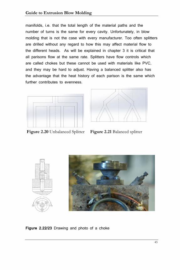
manifolds, i.e. that the total length of the material paths and the number of turns is the same for every cavity. Unfortunately, in blow molding that is not the case with every manufacturer. Too often splitters are drilled without any regard to how this may affect material flow to the different heads. As will be explained in chapter 3 it is critical that all parisons flow at the same rate. Splitters have flow controls which are called chokes but these cannot be used with materials like PVC, and they may be hard to adjust. Having a balanced splitter also has the advantage that the heat history of each parison is the same which further contributes to evenness.
Figure 2.20 Unbalanced Splitter Figure 2.21 Balanced splitter
Figure 2.22/23 Drawing and photo of a choke
2. Machine Components
46
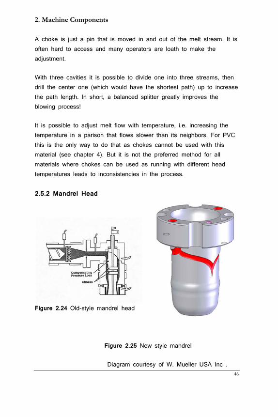
A choke is just a pin that is moved in and out of the melt stream. It is often hard to access and many operators are loath to make the adjustment.
With three cavities it is possible to divide one into three streams, then drill the center one (which would have the shortest path) up to increase the path length. In short, a balanced splitter greatly improves the blowing process!
It is possible to adjust melt flow with temperature, i.e. increasing the temperature in a parison that flows slower than its neighbors. For PVC this is the only way to do that as chokes cannot be used with this material (see chapter 4). But it is not the preferred method for all materials where chokes can be used as running with different head temperatures leads to inconsistencies in the process.
2.5.2 Mandrel Head
Figure 2.24 Old-style mandrel head
Figure 2.25 New style mandrel
Diagram courtesy of W. Mueller USA Inc .
Guide to Extrusion Blow Molding
47
This head type is characterized by a long mandrel in the center of the head to which the pin is attached. The horizontally moving melt hits the mandrel at the top of the head and moves around it. In old designs the two melt streams met at the other end of the mandrel where they had to re-knead. That made this spot weak to the point where it was possible to see this knead line in the finished container. A ring functioning as choke restricted the melt passage underneath forcing the melt to knead together at a higher pressure but even so the result was less than optimal. Additionally, the path of the melt at the entrance to the head was much shorter than the path at the other side. This led to flow imbalances that were sometimes corrected by adding an additional choke to the front section of the head only to slow down this part of the melt. All in all not a very good solution considering that the goal is to have a homogenous melt flowing at the same speed.
The improvement came with the insight that while there always had to be a weld line it did not have to go through the entire parison. Instead, the ‘parison over parison’ head (as it sometimes called) directs the melt to the front and the back of the mandrel at the same time and letting it run over two heart-shaped curves to form two weld lines, each going through half the parison thickness in places 180° from each other. This greatly improves container strength and has (since the initial patent expired) become the standard for virtually all mandrel heads.
The pin is attached to the end of the mandrel and head support air enters at the top of the latter flowing through the mandrel and pin into the parison. Whether this head is used in continuous extrusion or as accumulator head, the parison programmer always moves the pin.
2.5.3 Torpedo Head
In this design the melt changes direction before it enters the head. A bent pipe (often referred to as a ‘gooseneck’) with surrounding heater bands, or a square piece drilled from two sides and smoothed out is
2. Machine Components
48
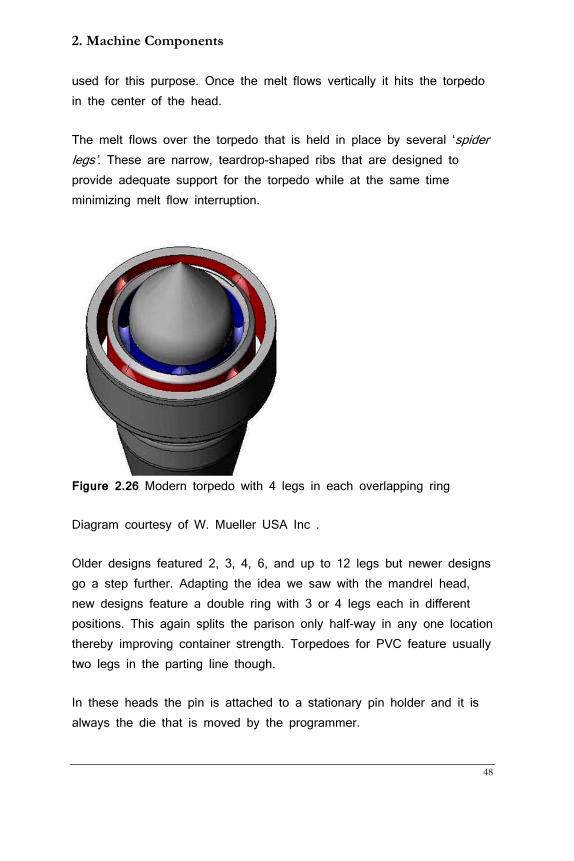
used for this purpose. Once the melt flows vertically it hits the torpedo in the center of the head.
The melt flows over the torpedo that is held in place by several ‘spider legs’. These are narrow, teardrop-shaped ribs that are designed to provide adequate support for the torpedo while at the same time minimizing melt flow interruption.
Figure 2.26 Modern torpedo with 4 legs in each overlapping ring
Diagram courtesy of W. Mueller USA Inc .
Older designs featured 2, 3, 4, 6, and up to 12 legs but newer designs go a step further. Adapting the idea we saw with the mandrel head, new designs feature a double ring with 3 or 4 legs each in different positions. This again splits the parison only half-way in any one location thereby improving container strength. Torpedoes for PVC feature usually two legs in the parting line though.
In these heads the pin is attached to a stationary pin holder and it is always the die that is moved by the programmer.
Guide to Extrusion Blow Molding
49
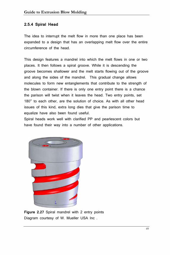
2.5.4 Spiral Head
The idea to interrupt the melt flow in more than one place has been expanded to a design that has an overlapping melt flow over the entire circumference of the head.
This design features a mandrel into which the melt flows in one or two places. It then follows a spiral groove. While it is descending the groove becomes shallower and the melt starts flowing out of the groove and along the sides of the mandrel. This gradual change allows molecules to form new entanglements that contribute to the strength of the blown container. If there is only one entry point there is a chance the parison will twist when it leaves the head. Two entry points, set 180° to each other, are the solution of choice. As with all other head issues of this kind, extra long dies that give the parison time to equalize have also been found useful. Spiral heads work well with clarified PP and pearlescent colors but have found their way into a number of other applications.
Figure 2.27 Spiral mandrel with 2 entry points Diagram courtesy of W. Mueller USA Inc .
2. Machine Components
50
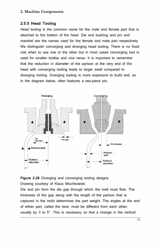
2.5.5 Head Tooling Head tooling is the common name for the male and female part that is attached to the bottom of the head. Die and bushing and pin and mandrel are the names used for the female and male part respectively. We distinguish converging and diverging head tooling. There is no fixed rule when to use one or the other but in most cases converging tool is used for smaller bottles and vice versa. It is important to remember that the reduction in diameter of the parison at the very end of the head with converging tooling leads to larger swell compared to diverging tooling. Diverging tooling is more expensive to build and, as in the diagram below, often features a two-piece pin.
Figure 2.28 Diverging and converging tooling designs Drawing courtesy of Klaus Mischkowski Die and pin form the die gap through which the melt must flow. The thickness of the gap along with the length of the parison that is captured in the mold determines the part weight. The angles at the end of either part, called the land, must be different from each other, usually by 3 to 5°. This is necessary so that a change in the vertical
Guide to Extrusion Blow Molding
51
direction of either one leads to a quicker change in the gap thickness as would be possible if they had the same angle. Pins must have a hole in the center to allow head support air to enter the parison. While the pin is either mounted to the mandrel in mandrel- style heads or to a pin holder in a torpedo-style head the die is always fastened with a ring that pushes its mounting flange against the head. The pin is always stationary in the horizontal direction and the die is moved to correct flow imbalances that lead to parison curling, i.e. the parison flowing to one side rather than straight. Care must be taken to tighten the ring enough to prevent leakage but not too much so as to make moving the die difficult.
2.6 Punch Punches literally ‘punch’ the bottom and neck flash off the container. They come in three varieties:
• Pneumatic devices that are mounted onto the platen
• Hydraulic devices that are stationary and one or two stations
removed from the blow pin station
• Completely separated devices that may deflash the container
either vertically or horizontally
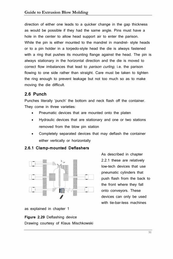
2.6.1 Clamp-mounted Deflashers As described in chapter 2.2.1 these are relatively low-tech devices that use pneumatic cylinders that push flash from the back to the front where they fall onto conveyors. These devices can only be used with tie-bar-less machines
as explained in chapter 1
Figure 2.29 Deflashing device Drawing courtesy of Klaus Mischkowski
2. Machine Components
52
Typically all tooling parts are made from aluminum. Take-out masks hold the container in place. Top and bottom push-bars move forward at the end of the cycle and strip flash off. At the bottom is a spring-loaded counter-bar that prevents the tail flash from bending up and sticking to the container.
2.6.2 Stationary Punch In machines that have intermediate deflash stations the punch is stationary in the back of the machine and driven by a hydraulic cylinder. The cylinder moves first into a position just short of reaching the molded parts. Air is introduced through a number of small holes and blows onto the flash for cooling. While there are other obstacles for fast cycle times flash cooling plays a big part and that is where the value of more elaborate deflash stations comes in.
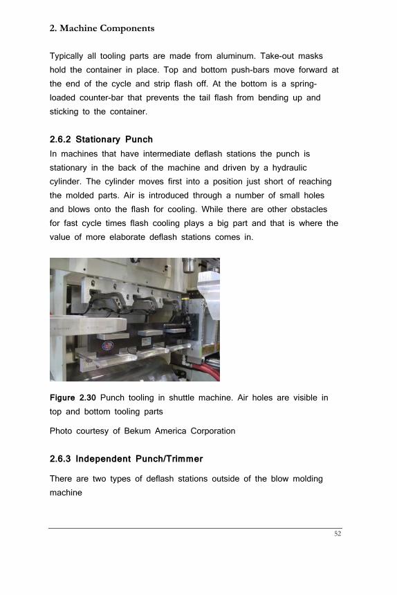
Figure 2.30 Punch tooling in shuttle machine. Air holes are visible in top and bottom tooling parts
Photo courtesy of Bekum America Corporation
2.6.3 Independent Punch/Trimmer
There are two types of deflash stations outside of the blow molding machine
Guide to Extrusion Blow Molding
53
• For upright bottles coming from blow and drop and some wheel
machines
• For lie-flat bottles coming from recip, wheel, and accumulator
head machines
In blow and drop machines bottles have to clear the molding area before the carriage can move towards the head (see chapter 1). In order to keep them oriented special take-out devices have been invented that grab bottles by their tail flash and move them onto a conveyor.
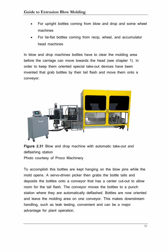
Figure 2.31 Blow and drop machine with automatic take-out and deflashing station Photo courtesy of Proco Machinery
To accomplish this bottles are kept hanging on the blow pins while the mold opens. A servo-driven picker then grabs the bottle tails and deposits the bottles onto a conveyor that has a center cut-out to allow room for the tail flash. The conveyor moves the bottles to a punch station where they are automatically deflashed. Bottles are now oriented and leave the molding area on one conveyor. This makes downstream handling, such as leak testing, convenient and can be a major advantage for plant operation.
2. Machine Components
54
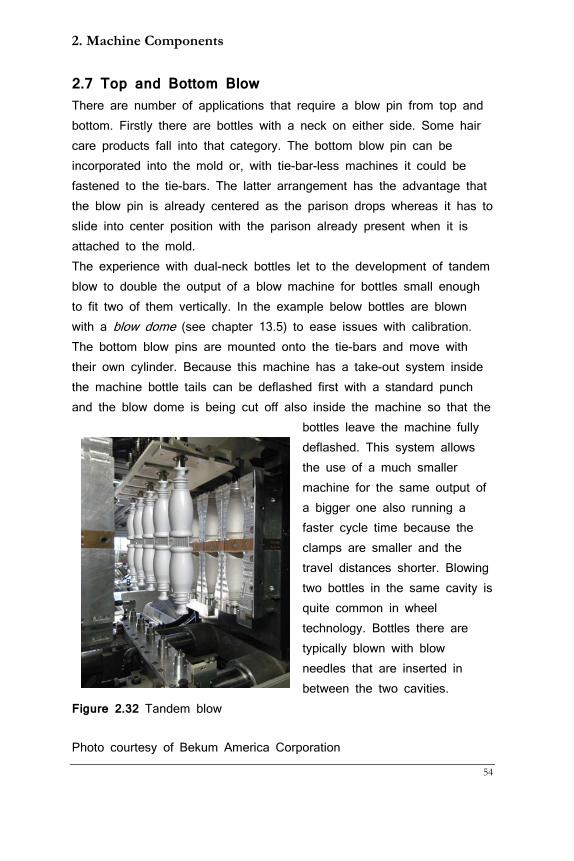
2.7 Top and Bottom Blow There are number of applications that require a blow pin from top and bottom. Firstly there are bottles with a neck on either side. Some hair care products fall into that category. The bottom blow pin can be incorporated into the mold or, with tie-bar-less machines it could be fastened to the tie-bars. The latter arrangement has the advantage that the blow pin is already centered as the parison drops whereas it has to slide into center position with the parison already present when it is attached to the mold. The experience with dual-neck bottles let to the development of tandem blow to double the output of a blow machine for bottles small enough to fit two of them vertically. In the example below bottles are blown with a blow dome (see chapter 13.5) to ease issues with calibration. The bottom blow pins are mounted onto the tie-bars and move with their own cylinder. Because this machine has a take-out system inside the machine bottle tails can be deflashed first with a standard punch and the blow dome is being cut off also inside the machine so that the
bottles leave the machine fully deflashed. This system allows the use of a much smaller machine for the same output of a bigger one also running a faster cycle time because the clamps are smaller and the travel distances shorter. Blowing two bottles in the same cavity is quite common in wheel technology. Bottles there are typically blown with blow needles that are inserted in between the two cavities.
Figure 2.32 Tandem blow
Photo courtesy of Bekum America Corporation
Guide to Extrusion Blow Molding
55
2.8 In Mold Labeling (IML)
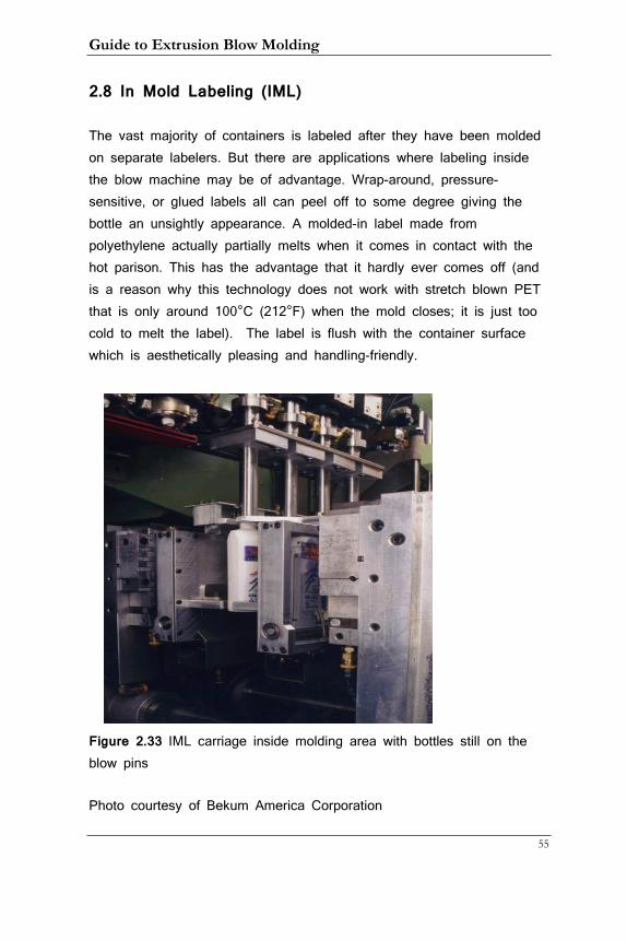
The vast majority of containers is labeled after they have been molded on separate labelers. But there are applications where labeling inside the blow machine may be of advantage. Wrap-around, pressure-sensitive, or glued labels all can peel off to some degree giving the bottle an unsightly appearance. A molded-in label made from polyethylene actually partially melts when it comes in contact with the hot parison. This has the advantage that it hardly ever comes off (and is a reason why this technology does not work with stretch blown PET that is only around 100°C (212°F) when the mold closes; it is just too cold to melt the label). The label is flush with the container surface which is aesthetically pleasing and handling-friendly.
Figure 2.33 IML carriage inside molding area with bottles still on the blow pins
Photo courtesy of Bekum America Corporation
2. Machine Components
56
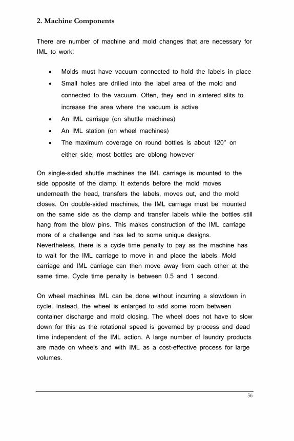
There are number of machine and mold changes that are necessary for IML to work:
• Molds must have vacuum connected to hold the labels in place
• Small holes are drilled into the label area of the mold and
connected to the vacuum. Often, they end in sintered slits to
increase the area where the vacuum is active
• An IML carriage (on shuttle machines)
• An IML station (on wheel machines)
• The maximum coverage on round bottles is about 120° on
either side; most bottles are oblong however
On single-sided shuttle machines the IML carriage is mounted to the side opposite of the clamp. It extends before the mold moves underneath the head, transfers the labels, moves out, and the mold closes. On double-sided machines, the IML carriage must be mounted on the same side as the clamp and transfer labels while the bottles still hang from the blow pins. This makes construction of the IML carriage more of a challenge and has led to some unique designs. Nevertheless, there is a cycle time penalty to pay as the machine has to wait for the IML carriage to move in and place the labels. Mold carriage and IML carriage can then move away from each other at the same time. Cycle time penalty is between 0.5 and 1 second.
On wheel machines IML can be done without incurring a slowdown in cycle. Instead, the wheel is enlarged to add some room between container discharge and mold closing. The wheel does not have to slow down for this as the rotational speed is governed by process and dead time independent of the IML action. A large number of laundry products are made on wheels and with IML as a cost-effective process for large volumes.
Guide to Extrusion Blow Molding
57
3. Parison Programming (or Wall Thickness Control)
Container shapes vary a great deal along their length axis. Starting from the top, there is often a neck that is usually smaller than the container body. However, the neck may be thick whereas the body is thin. Then comes the shoulder where also less material is required. Towards the bottom we often have a thin spot (see chapter 6.1) where we would like to have more material to satisfy a minimum wall thickness requirement. And the bottom of the container has its own specific, optimal wall thickness. Technical parts have often very unique shapes that also require very specific wall thickness control.
3.1 Function of the Programmer
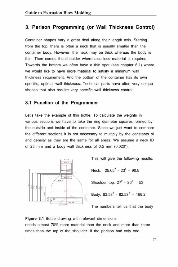
Let’s take the example of this bottle. To calculate the weights in various sections we have to take the ring diameter squares formed by the outside and inside of the container. Since we just want to compare the different sections it is not necessary to multiply by the constants pi and density as they are the same for all areas. We assume a neck ID of 23 mm and a body wall thickness of 0.5 mm (0.020”).
This will give the following results:
Neck: 25.052 – 232 = 98.5
Shoulder top: 272 – 262 = 53
Body: 83.582 – 82.582 = 166.2
The numbers tell us that the body
Figure 3.1 Bottle drawing with relevant dimensions needs almost 70% more material than the neck and more than three times than the top of the shoulder. If the parison had only one
3. Parison Programming
58
thickness we would need to make it thick enough to get the wall thickness in the bottom and that would lead to a very thick neck and shoulder. This would not only lead to a very heavy container but would also require a very long cooling time to cool down the thickest part.
So it is obvious that it would be very difficult to make a functional and economical container with a parison of even thickness. Here is where parison programming comes in. It allows the operator to tailor the parison wall thickness to the wall thickness requirements of the bottle. This is accomplished by varying the gap between pin and die as the parison extrudes from the head.
Parison programming was invented by Denes Hunkar in the late 50s. It has since undergone many improvements but the main principle is still the same. The length of the parison is divided into steps and the operator can assign a discrete value to each step that translates into a gap width. This allows a parison thickness profile that mimics the container requirements and so saves material and cycle time, a true win/win situation.
Figure 3.2 Early programmers used pins to create a program that moved from left to right
Photo courtesy of Hunkar Technologies
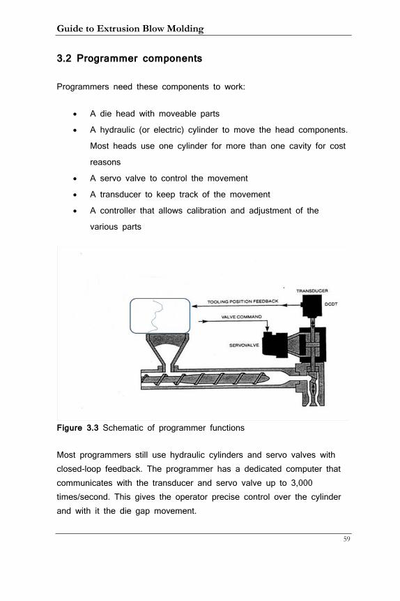
Guide to Extrusion Blow Molding
59
3.2 Programmer components
Programmers need these components to work:
• A die head with moveable parts
• A hydraulic (or electric) cylinder to move the head components.
Most heads use one cylinder for more than one cavity for cost
reasons
• A servo valve to control the movement
• A transducer to keep track of the movement
• A controller that allows calibration and adjustment of the
various parts
Figure 3.3 Schematic of programmer functions
Most programmers still use hydraulic cylinders and servo valves with closed-loop feedback. The programmer has a dedicated computer that communicates with the transducer and servo valve up to 3,000 times/second. This gives the operator precise control over the cylinder and with it the die gap movement.
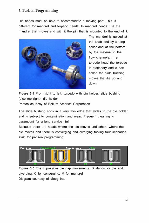
3. Parison Programming
60
Die heads must be able to accommodate a moving part. This is different for mandrel and torpedo heads. In mandrel heads it is the mandrel that moves and with it the pin that is mounted to the end of it.
The mandrel is guided at the shaft end by a long collar and at the bottom by the material in the flow channels. In a torpedo head the torpedo is stationary and a part called the slide bushing moves the die up and down.
Figure 3.4 From right to left: torpedo with pin holder, slide bushing (also top right), die holder Photos courtesy of Bekum America Corporation
The slide bushing ends in a very thin edge that slides in the die holder and is subject to contamination and wear. Frequent cleaning is paramount for a long service life! Because there are heads where the pin moves and others where the die moves and there is converging and diverging tooling four scenarios exist for parison programming:
Figure 3.5 The 4 possible die gap movements. D stands for die and diverging, C for converging, M for mandrel Diagram courtesy of Moog Inc.
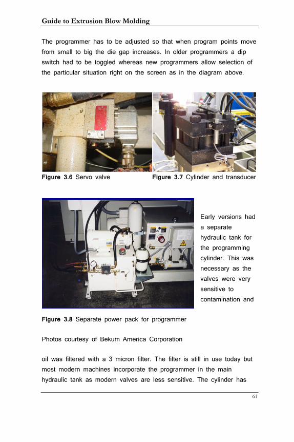
Guide to Extrusion Blow Molding
61
The programmer has to be adjusted so that when program points move from small to big the die gap increases. In older programmers a dip switch had to be toggled whereas new programmers allow selection of the particular situation right on the screen as in the diagram above.
Figure 3.6 Servo valve Figure 3.7 Cylinder and transducer
Early versions had a separate hydraulic tank for the programming cylinder. This was necessary as the valves were very sensitive to contamination and
Figure 3.8 Separate power pack for programmer
Photos courtesy of Bekum America Corporation
oil was filtered with a 3 micron filter. The filter is still in use today but most modern machines incorporate the programmer in the main hydraulic tank as modern valves are less sensitive. The cylinder has
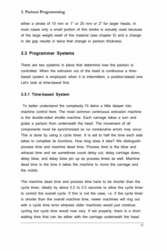
3. Parison Programming
62
either a stroke of 10 mm or 1” or 20 mm or 2” for larger heads. In most cases only a small portion of this stroke is actually used because of the large weight swell of the material (see chapter 5) and a change in die gap results in twice that change in parison thickness.
3.3 Programmer Systems
There are two systems in place that determine how the parison is controlled. When the extrusion out of the head is continuous a time-based system is employed; when it is intermittent, a position-based one. Let’s look at time-based first.
3.3.1 Time-based System
To better understand the complexity I’ll delve a little deeper into machine control here. The most common continuous extrusion machine is the double-sided shuttle machine. Each carriage takes a turn and grabs a parison from underneath the head. The movement of all components must be synchronized so no consecutive errors may occur. This is done by using a cycle timer. It is set to half the time each side takes to complete its functions. How long does it take? We distinguish process time and machine dead time. Process time is the blow and exhaust time and we sometimes count delay cut, delay carriage down, delay blow, and delay blow pin up as process times as well. Machine dead time is the time it takes the machine to move the carriage and the molds.
The machine dead time and process time have to be shorter than the cycle timer, ideally by about 0.2 to 0.3 seconds to allow the cycle timer to control the overall cycle. If this is not the case, i.e. if the cycle timer is shorter than the overall machine time, newer machines will ring out with a cycle time error whereas older machines would just continue cycling but cycle time would now vary. If set properly, there is a short waiting time that can be either with the carriage underneath the head

Guide to Extrusion Blow Molding
63
and the mold closing when the cycle timer times out or with the carriage waiting with the mold open in the blow pin station and the carriage moving to the head station when the cycle timer times out. Either way, it is the job of the processor to adjust the cycle timer just right so as to not waste time if it is set too long or cause a cycle time error when it is set too short.
How does the programmer fit into this control? In modern machines the programmer is dependent on the machine cycle and does not control it. Rather, time-based programmers measure the time between knife cuts and adjust the time interval between two consecutive events to organize the time each programming point is active. For example, if the programmer has 100 points and the time between knife cuts is 10 s, each programming point is active for 0.1 seconds.
3.3.2 Position-Based System
All intermittent EBM machines cannot use time to control the parison wall thickness. Instead they use the length of the parison as the yardstick to assign programming points. Recip machines use a transducer connected to the screw whereas accumulator head machines use a transducer that is connected to the ram that pushes the parison out of the head. For the push-out to start two conditions must be met:
• The accumulator or screw must be at set point
• The mold must be open and ready to accept a new part
The cycle timer plays less of a role on most machines; it just records the time between two cycles. Often, a waiting timer displays the time between the instance the mold was ready and the push-out started. This allows the operator to set the extruder rpm to suit.
Each program point is assigned a measurement rather than a time value. If the push-out transducer reads 200 mm and the programmer again has 100 points each point is assigned 2 mm.
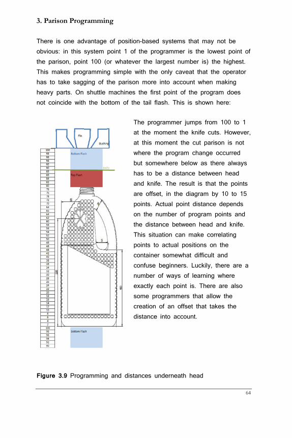
3. Parison Programming
64
There is one advantage of position-based systems that may not be obvious: in this system point 1 of the programmer is the lowest point of the parison, point 100 (or whatever the largest number is) the highest. This makes programming simple with the only caveat that the operator has to take sagging of the parison more into account when making heavy parts. On shuttle machines the first point of the program does not coincide with the bottom of the tail flash. This is shown here:
The programmer jumps from 100 to 1 at the moment the knife cuts. However, at this moment the cut parison is not where the program change occurred but somewhere below as there always has to be a distance between head and knife. The result is that the points are offset, in the diagram by 10 to 15 points. Actual point distance depends on the number of program points and the distance between head and knife. This situation can make correlating points to actual positions on the container somewhat difficult and confuse beginners. Luckily, there are a number of ways of learning where exactly each point is. There are also some programmers that allow the creation of an offset that takes the distance into account.
Figure 3.9 Programming and distances underneath head
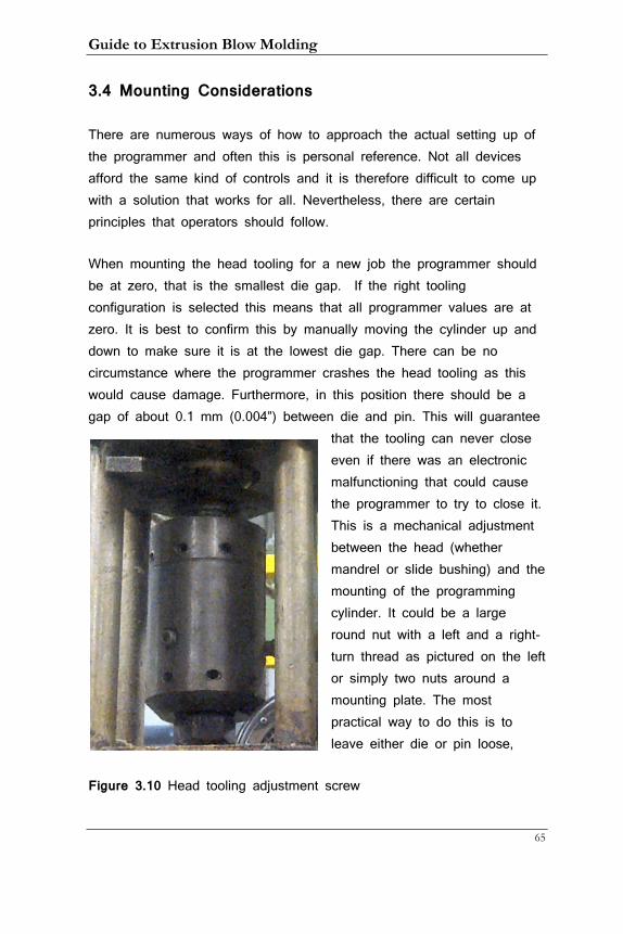
Guide to Extrusion Blow Molding
65
3.4 Mounting Considerations
There are numerous ways of how to approach the actual setting up of the programmer and often this is personal reference. Not all devices afford the same kind of controls and it is therefore difficult to come up with a solution that works for all. Nevertheless, there are certain principles that operators should follow.
When mounting the head tooling for a new job the programmer should be at zero, that is the smallest die gap. If the right tooling configuration is selected this means that all programmer values are at zero. It is best to confirm this by manually moving the cylinder up and down to make sure it is at the lowest die gap. There can be no circumstance where the programmer crashes the head tooling as this would cause damage. Furthermore, in this position there should be a gap of about 0.1 mm (0.004”) between die and pin. This will guarantee
that the tooling can never close even if there was an electronic malfunctioning that could cause the programmer to try to close it. This is a mechanical adjustment between the head (whether mandrel or slide bushing) and the mounting of the programming cylinder. It could be a large round nut with a left and a right-turn thread as pictured on the left or simply two nuts around a mounting plate. The most practical way to do this is to leave either die or pin loose,
Figure 3.10 Head tooling adjustment screw
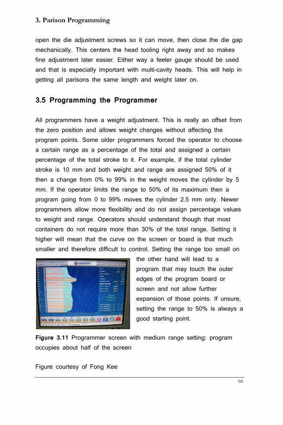
3. Parison Programming
66
open the die adjustment screws so it can move, then close the die gap mechanically. This centers the head tooling right away and so makes fine adjustment later easier. Either way a feeler gauge should be used and that is especially important with multi-cavity heads. This will help in getting all parisons the same length and weight later on.
3.5 Programming the Programmer
All programmers have a weight adjustment. This is really an offset from the zero position and allows weight changes without affecting the program points. Some older programmers forced the operator to choose a certain range as a percentage of the total and assigned a certain percentage of the total stroke to it. For example, if the total cylinder stroke is 10 mm and both weight and range are assigned 50% of it then a change from 0% to 99% in the weight moves the cylinder by 5 mm. If the operator limits the range to 50% of its maximum then a program going from 0 to 99% moves the cylinder 2.5 mm only. Newer programmers allow more flexibility and do not assign percentage values to weight and range. Operators should understand though that most containers do not require more than 30% of the total range. Setting it higher will mean that the curve on the screen or board is that much smaller and therefore difficult to control. Setting the range too small on
the other hand will lead to a program that may touch the outer edges of the program board or screen and not allow further expansion of those points. If unsure, setting the range to 50% is always a good starting point.
Figure 3.11 Programmer screen with medium range setting: program occupies about half of the screen
Figure courtesy of Fong Kee
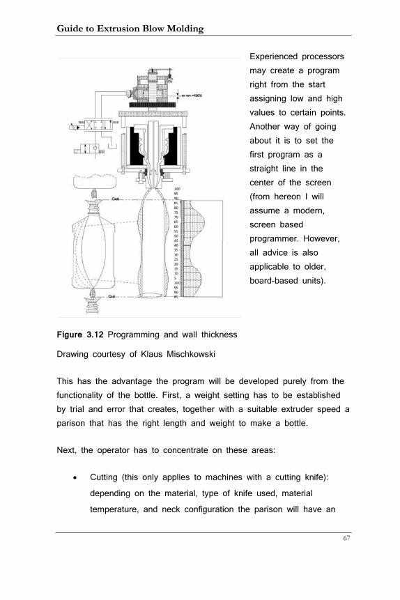
Guide to Extrusion Blow Molding
67
Experienced processors may create a program right from the start assigning low and high values to certain points. Another way of going about it is to set the first program as a straight line in the center of the screen (from hereon I will assume a modern, screen based programmer. However, all advice is also applicable to older, board-based units).
Figure 3.12 Programming and wall thickness
Drawing courtesy of Klaus Mischkowski
This has the advantage the program will be developed purely from the functionality of the bottle. First, a weight setting has to be established by trial and error that creates, together with a suitable extruder speed a parison that has the right length and weight to make a bottle.
Next, the operator has to concentrate on these areas:
• Cutting (this only applies to machines with a cutting knife):
depending on the material, type of knife used, material
temperature, and neck configuration the parison will have an
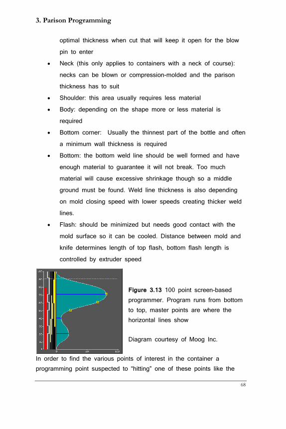
3. Parison Programming
68
optimal thickness when cut that will keep it open for the blow
pin to enter
• Neck (this only applies to containers with a neck of course):
necks can be blown or compression-molded and the parison
thickness has to suit
• Shoulder: this area usually requires less material
• Body: depending on the shape more or less material is
required
• Bottom corner: Usually the thinnest part of the bottle and often
a minimum wall thickness is required
• Bottom: the bottom weld line should be well formed and have
enough material to guarantee it will not break. Too much
material will cause excessive shrinkage though so a middle
ground must be found. Weld line thickness is also depending
on mold closing speed with lower speeds creating thicker weld
lines.
• Flash: should be minimized but needs good contact with the
mold surface so it can be cooled. Distance between mold and
knife determines length of top flash, bottom flash length is
controlled by extruder speed
Figure 3.13 100 point screen-based programmer. Program runs from bottom to top, master points are where the horizontal lines show
Diagram courtesy of Moog Inc.
In order to find the various points of interest in the container a programming point suspected to “hitting” one of these points like the
Guide to Extrusion Blow Molding
69
bottom corner can be either dialed in very low or very high and the result can then be seen in the container and the correct point thus found. The points where a program change occurs are referred to as master points. On some units by simply manually changing a point it becomes a master point; on other units a master point has to be declared explicitly. The programmer then connects the master points in a user-selectable way with sharp or smooth transitions. It is worth noting that there is a limit on how fast the hydraulic cylinder can react to changes in the program. On screen-based programmers the unit actually tells the user what the cylinder did by posting a separate line besides the program line. Too sharp of a program change that cannot be followed by the hydraulics is not practical; it is better to make a program that the cylinder can follow. All programmers offer a parabolic connection between master points and in most cases this is the best setting to use.
There is a so-called gain setting that determines how quickly the controller reacts to a change of input. It is worth experimenting with this value. First increase it until the unit starts to oscillate (overshooting and undershooting), then lower it until the oscillations stop. This setting assures the best response time yielding a responsive unit.
Position-based systems follow similar rules but have added characteristics. With an accumulator head system the operator can often dial in a hydraulic pressure against which the extruder has to work to fill the head. This creates back pressure that can help in mixing the material more thoroughly. Too much of it however will increase the melt temperature. While the push-out time cannot be dialed in directly (it is only displayed on the screen for reference) the hydraulic push-out pressure and/or flow can be adjusted and will in turn control the push-out speed.
Sagging is often an issue with heavy parisons and this can be improved upon by adding material to the top portion of points.
3. Parison Programming
70
Operators should also take advantage of pre-closing the mold to a position that leaves just enough room for the parison to extend between the mold halves. This reduces the time the mold needs to close and gives the parison less time to sag.
3.6 Multi-cavity Heads
When running more than one cavity it is paramount that all parisons have the same length and weight. Length is important because it determines where the various programmed points end up in the container. If one parison is longer than another the parison program will be skewed and container variation is unavoidable.
Starting from an equal minimum die gap for each head helps with this enormously and is highly recommended. Just keep in mind that any mechanical adjustment that may become necessary has to increase the die gap. Decreasing it would reduce the safety gap! First, make the parisons the same length with the help of the chokes. They should be turned out all the way before you start, then turn them in for the parisons that are the longest. Now weigh full shots, that is container and flash, of each cavity and compare them. Mechanically increase the weight of the light ones, check again for tail length. This going back and forth between choke and mechanical weight adjustment may have to be done a few times before every tail has the same length and every container the same weight. When working with PVC chokes cannot be used. Instead head temperatures should be changed to get even tail length. This is not optimal but so far no other control is available,
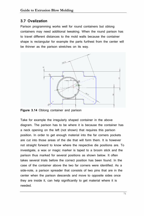
Guide to Extrusion Blow Molding
71
3.7 Ovalization Parison programming works well for round containers but oblong containers may need additional tweaking. When the round parison has to travel different distances to the mold walls because the container shape is rectangular for example the parts furthest from the center will be thinner as the parison stretches on its way.
Figure 3.14 Oblong container and parison
Take for example the irregularly shaped container in the above diagram. The parison has to be where it is because the container has a neck opening on the left (not shown) that requires this parison position. In order to get enough material into the far corners pockets are cut into those areas of the die that will form them. It is however not straight forward to know where the respective die positions are. To investigate, a wax or magic marker is taped to a broom stick and the parison thus marked for several positions as shown below. It often takes several trials before the correct position has been found. In the case of the container above the two far corners were identified. As a side-note, a parison spreader that consists of two pins that are in the center when the parison descends and move to opposite sides once they are inside it, can help significantly to get material where it is needed.
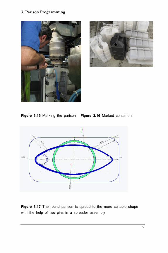
3. Parison Programming
72
Figure 3.15 Marking the parison Figure 3.16 Marked containers
Figure 3.17 The round parison is spread to the more suitable shape with the help of two pins in a spreader assembly
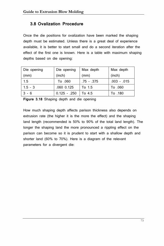
Guide to Extrusion Blow Molding
73
3.8 Ovalization Procedure
Once the die positions for ovalization have been marked the shaping depth must be estimated. Unless there is a great deal of experience available, it is better to start small and do a second iteration after the effect of the first one is known. Here is a table with maximum shaping depths based on die opening:
Die opening (mm)
Die opening (inch)
Max depth (mm)
Max depth (inch)
1.5 To .060 .75 - .375 .003 - .015 1.5 – 3 .060 0.125 To 1.5 To .060 3 - 6 0.125 - .250 To 4.5 To .180 Figure 3.18 Shaping depth and die opening
How much shaping depth affects parison thickness also depends on extrusion rate (the higher it is the more the effect) and the shaping land length (recommended is 50% to 90% of the total land length). The longer the shaping land the more pronounced a rippling effect on the parison can become so it is prudent to start with a shallow depth and shorter land (60% to 70%). Here is a diagram of the relevant parameters for a divergent die:
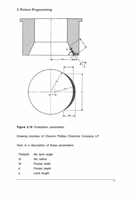
3. Parison Programming
74
Figure 3.19 Ovalization parameters
Drawing courtesy of Chevron Phillips Chemical Company LP
Here is a description of these parameters:
Theta(θ) die land angle rb die radius W Pocket width d Pocket depth a Land length
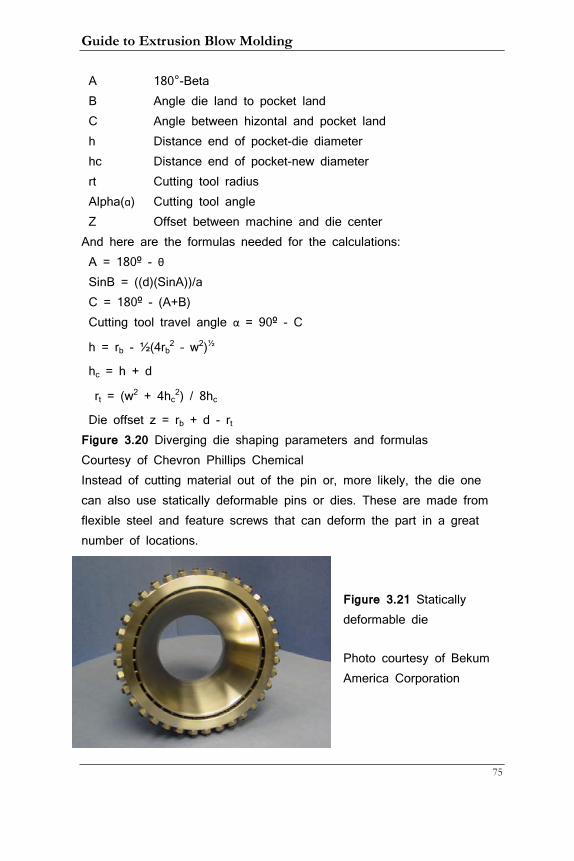
Guide to Extrusion Blow Molding
75
A 180°-Beta B Angle die land to pocket land C Angle between hizontal and pocket land h Distance end of pocket-die diameter hc Distance end of pocket-new diameter rt Cutting tool radius Alpha(ɑ) Cutting tool angle Z Offset between machine and die center
And here are the formulas needed for the calculations: A = 180º - θ SinB = ((d)(SinA))/a C = 180º - (A+B) Cutting tool travel angle α = 90º - C
h = rb - ½(4rb2 – w2)½
hc = h + d
rt = (w2 + 4hc2) / 8hc
Die offset z = rb + d - rt Figure 3.20 Diverging die shaping parameters and formulas Courtesy of Chevron Phillips Chemical Instead of cutting material out of the pin or, more likely, the die one can also use statically deformable pins or dies. These are made from flexible steel and feature screws that can deform the part in a great number of locations.
Figure 3.21 Statically deformable die
Photo courtesy of Bekum America Corporation
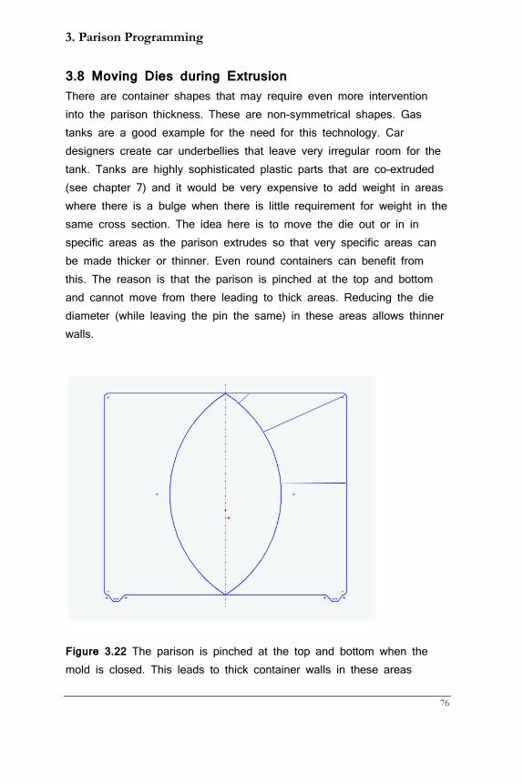
3. Parison Programming
76
3.8 Moving Dies during Extrusion There are container shapes that may require even more intervention into the parison thickness. These are non-symmetrical shapes. Gas tanks are a good example for the need for this technology. Car designers create car underbellies that leave very irregular room for the tank. Tanks are highly sophisticated plastic parts that are co-extruded (see chapter 7) and it would be very expensive to add weight in areas where there is a bulge when there is little requirement for weight in the same cross section. The idea here is to move the die out or in in specific areas as the parison extrudes so that very specific areas can be made thicker or thinner. Even round containers can benefit from this. The reason is that the parison is pinched at the top and bottom and cannot move from there leading to thick areas. Reducing the die diameter (while leaving the pin the same) in these areas allows thinner walls.
Figure 3.22 The parison is pinched at the top and bottom when the mold is closed. This leads to thick container walls in these areas
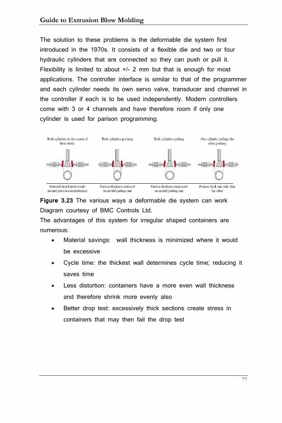
Guide to Extrusion Blow Molding
77
The solution to these problems is the deformable die system first introduced in the 1970s. It consists of a flexible die and two or four hydraulic cylinders that are connected so they can push or pull it. Flexibility is limited to about +/- 2 mm but that is enough for most applications. The controller interface is similar to that of the programmer and each cylinder needs its own servo valve, transducer and channel in the controller if each is to be used independently. Modern controllers come with 3 or 4 channels and have therefore room if only one cylinder is used for parison programming.
Figure 3.23 The various ways a deformable die system can work Diagram courtesy of BMC Controls Ltd. The advantages of this system for irregular shaped containers are numerous:
• Material savings: wall thickness is minimized where it would
be excessive
• Cycle time: the thickest wall determines cycle time; reducing it
saves time
• Less distortion: containers have a more even wall thickness
and therefore shrink more evenly also
• Better drop test: excessively thick sections create stress in
containers that may then fail the drop test
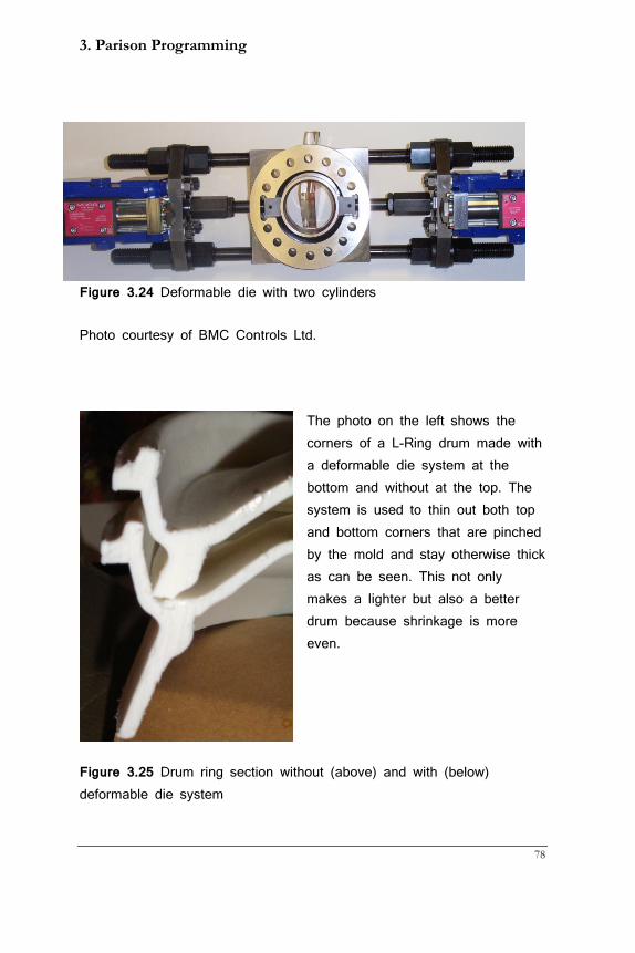
3. Parison Programming
78
Figure 3.24 Deformable die with two cylinders
Photo courtesy of BMC Controls Ltd.
The photo on the left shows the corners of a L-Ring drum made with a deformable die system at the bottom and without at the top. The system is used to thin out both top and bottom corners that are pinched by the mold and stay otherwise thick as can be seen. This not only makes a lighter but also a better drum because shrinkage is more even.
Figure 3.25 Drum ring section without (above) and with (below) deformable die system
Guide to Extrusion Blow Molding
79
4. EBM Materials
High density polyethylene (HDPE) was invented in the 1950s and it was the catalyst that transformed EBM from a niche process for specialty products to a mass market force. It is still the most widely used material in the process. Before we discuss the properties of this and other blow-moldable materials a little excursion in material science may be appropriate.
4.1 Production of Plastics
All plastics consist of long chains of repeating units. They are called polymers as “poly” means many and “mer” is a single unit. Polymers are also found in nature and it is possible to make plastics out of natural substances as the advent of bio resins has proven. However, most plastics are still made from petroleum products. In the US polyolefins (HDPE, LDPE, and PP) are made from natural gas, whereas oil is used in other parts of the world as feedstock.
Plastics mainly consist of the elements carbon (“C”), hydrogen (“H”), and oxygen (“O”). Other elements such as fluorine (“F”), Sulfur (“S”), and chlorine (“Cl”) may also be part of them. Plastics form large
molecules of repeating units but start with small molecules that are strung together in a process called polymerization. The following is an example of how HDPE is made from natural gas.
Figure 4.1 Methane molecule; here as in all other graphics, the inner-shell electrons are not shown
4. EBM Materials
80
The simplest of these starting blocks in natural gas is Methane as pictured above. It has 1 carbon and 4 hydrogen molecules. The black dots are the shared electrons in a covalent bond. It can be written as CH4 and is produced when oil or natural gas go through a “cracker” where these and other petroleum products are distilled. Methane is not a good starting point for HDPE production but ethane is. The percentage of ethane in natural gas is smaller than methane but it is of high value as an industrial building block.
Figure 4.2 Ethane molecule Here we have two carbon atoms that are linked together with a single bond whereas the other three electrons of carbon share a bond with three hydrogen atoms. It is written as C2H6 and still not really suitable to produce a long chain. The next step is the ethene molecule.
Figure 4.3 Ethene molecule written as C2H4
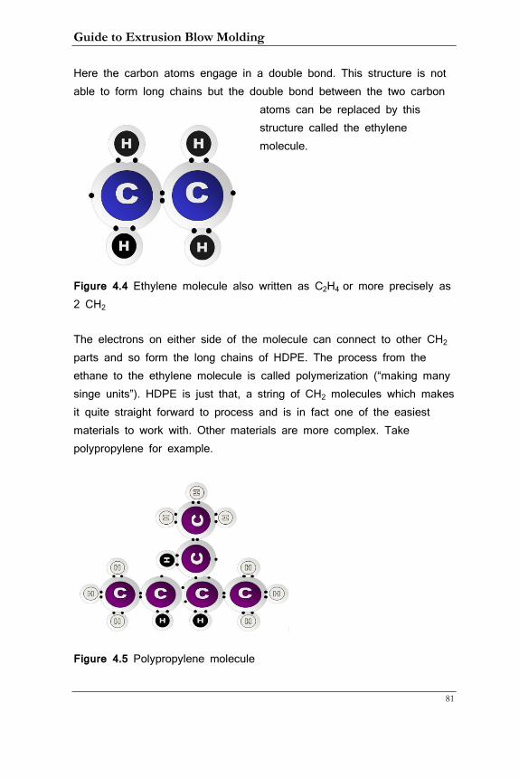
Guide to Extrusion Blow Molding
81
Here the carbon atoms engage in a double bond. This structure is not able to form long chains but the double bond between the two carbon
atoms can be replaced by this structure called the ethylene molecule.
Figure 4.4 Ethylene molecule also written as C2H4 or more precisely as 2 CH2
The electrons on either side of the molecule can connect to other CH2 parts and so form the long chains of HDPE. The process from the ethane to the ethylene molecule is called polymerization (“making many singe units”). HDPE is just that, a string of CH2 molecules which makes it quite straight forward to process and is in fact one of the easiest materials to work with. Other materials are more complex. Take polypropylene for example.
Figure 4.5 Polypropylene molecule
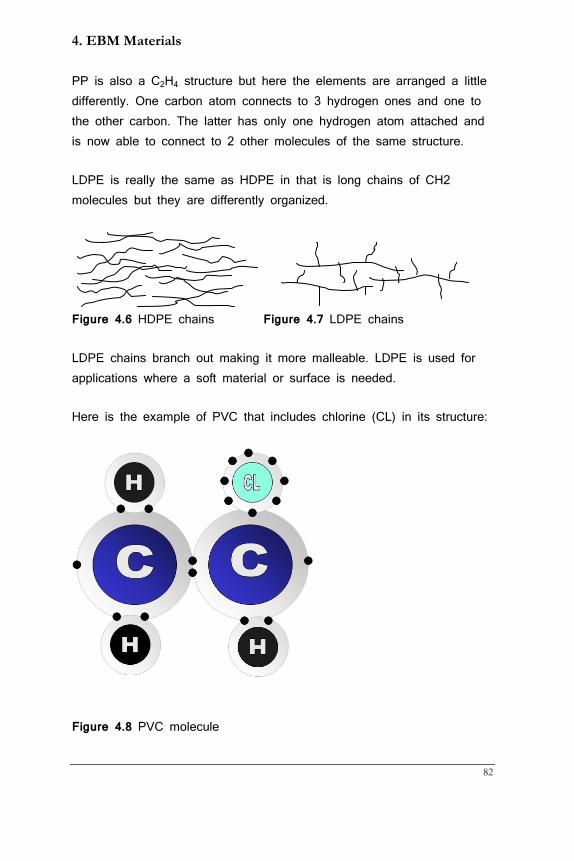
4. EBM Materials
82
PP is also a C2H4 structure but here the elements are arranged a little differently. One carbon atom connects to 3 hydrogen ones and one to the other carbon. The latter has only one hydrogen atom attached and is now able to connect to 2 other molecules of the same structure.
LDPE is really the same as HDPE in that is long chains of CH2 molecules but they are differently organized.
Figure 4.6 HDPE chains Figure 4.7 LDPE chains
LDPE chains branch out making it more malleable. LDPE is used for applications where a soft material or surface is needed.
Here is the example of PVC that includes chlorine (CL) in its structure:
Figure 4.8 PVC molecule
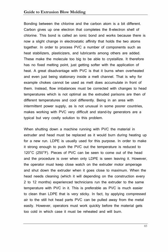
Guide to Extrusion Blow Molding
83
Bonding between the chlorine and the carbon atom is a bit different. Carbon gives up one electron that completes the 8-electron shell of chlorine. This bond is called an ionic bond and works because there is now a slight change in electrostatic affinity that holds the two atoms together. In order to process PVC a number of components such as heat stabilizers, plasticizers, and lubricants among others are added. These make the molecule too big to be able to crystallize. It therefore has no fixed melting point, just getting softer with the application of heat. A great disadvantage with PVC is that it burns when overheated and even just being stationary inside a melt channel. That is why for example chokes cannot be used as melt does accumulate in front of them. Instead, flow imbalances must be corrected with changes to head temperatures which is not optimal as the extruded parisons are then of different temperatures and cool differently. Being in an area with intermittent power supply, as is not unusual in some poorer countries, makes working with PVC very difficult and stand-by generators are a typical but very costly solution to this problem.
When shutting down a machine running with PVC the material in extruder and head must be replaced as it would burn during heating up for a new run. LDPE is usually used for this purpose. In order to make it strong enough to push the PVC out the temperature is reduced to 120°C (250°F). Pieces of PVC can be seen to come out of the head and the procedure is over when only LDPE is seen leaving it. However, the operator must keep close watch on the extruder motor amperage and shut down the extruder when it goes close to maximum. When the head needs cleaning (which it will depending on the construction every 2 to 12 months) experienced technicians run the extruder to the same temperature with PVC in it. This is preferable as PVC is much easier to clean than LDPE that is very sticky. In fact, by applying compressed air to the still hot head parts PVC can be pulled away from the metal easily. However, operators must work quickly before the material gets too cold in which case it must be reheated and will burn.
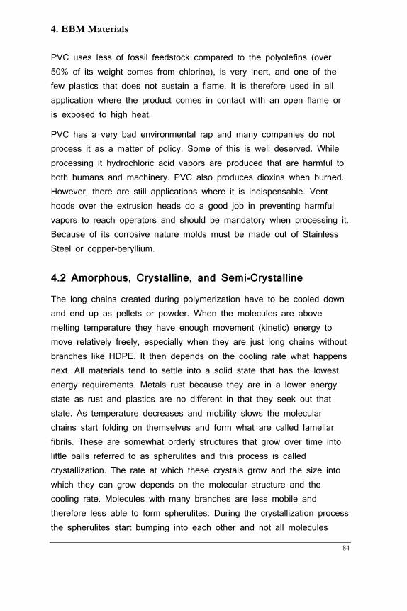
4. EBM Materials
84
PVC uses less of fossil feedstock compared to the polyolefins (over 50% of its weight comes from chlorine), is very inert, and one of the few plastics that does not sustain a flame. It is therefore used in all application where the product comes in contact with an open flame or is exposed to high heat.
PVC has a very bad environmental rap and many companies do not process it as a matter of policy. Some of this is well deserved. While processing it hydrochloric acid vapors are produced that are harmful to both humans and machinery. PVC also produces dioxins when burned. However, there are still applications where it is indispensable. Vent hoods over the extrusion heads do a good job in preventing harmful vapors to reach operators and should be mandatory when processing it. Because of its corrosive nature molds must be made out of Stainless Steel or copper-beryllium.
4.2 Amorphous, Crystalline, and Semi-Crystalline
The long chains created during polymerization have to be cooled down and end up as pellets or powder. When the molecules are above melting temperature they have enough movement (kinetic) energy to move relatively freely, especially when they are just long chains without branches like HDPE. It then depends on the cooling rate what happens next. All materials tend to settle into a solid state that has the lowest energy requirements. Metals rust because they are in a lower energy state as rust and plastics are no different in that they seek out that state. As temperature decreases and mobility slows the molecular chains start folding on themselves and form what are called lamellar fibrils. These are somewhat orderly structures that grow over time into little balls referred to as spherulites and this process is called crystallization. The rate at which these crystals grow and the size into which they can grow depends on the molecular structure and the cooling rate. Molecules with many branches are less mobile and therefore less able to form spherulites. During the crystallization process the spherulites start bumping into each other and not all molecules
Guide to Extrusion Blow Molding
85
have the opportunity to form them. Therefore, no plastic can be completely crystalline; we call them semi-crystalline as a result. HDPE, PP and PET are of this type of plastic.
Other materials do not form any or very few spherulites. These are plastics with heavy branching that prevent the necessary mobility to form them. Instead, these plastics stay un-oriented (amorphous). Plastics of this type are PVC, PS, and ABS. LDPE also falls into this category. This makes it less strong but gives it better stress crack resistance as the structure is less rigid.
It is important to understand that all plastics are amorphous (un-oriented) in the melting state. This is because at a temperature above melting point the molecules have enough energy to move around relatively freely and all spherulites are dissolved. The difference between the semi-crystalline and amorphous materials then is that the former have a fixed melting point at which the crystals dissolve whereas amorphous materials just become softer and softer as temperature increases. As we will see in chapter 6 this has consequences for the process that the operator should understand.
When the molten plastic solidifies in the blow mold crystallinity can also be created for those materials that are prone to it. The level of crystallinity depends again on the rate of cooling and that in turn depends on how cold the mold is, how quickly the mold material can cool the plastic, and how thick the plastic is. For example, heavy container walls will show more crystallinity on the outside where they cool down quickly as they being pushed against the cold mold wall and less crystallinity on the inside that had a longer time to cool. High crystallinity levels are advantageous as they enhance mechanical properties. Fast cooling reduces the size of the crystals and this leads to a tougher, less brittle and clearer container.
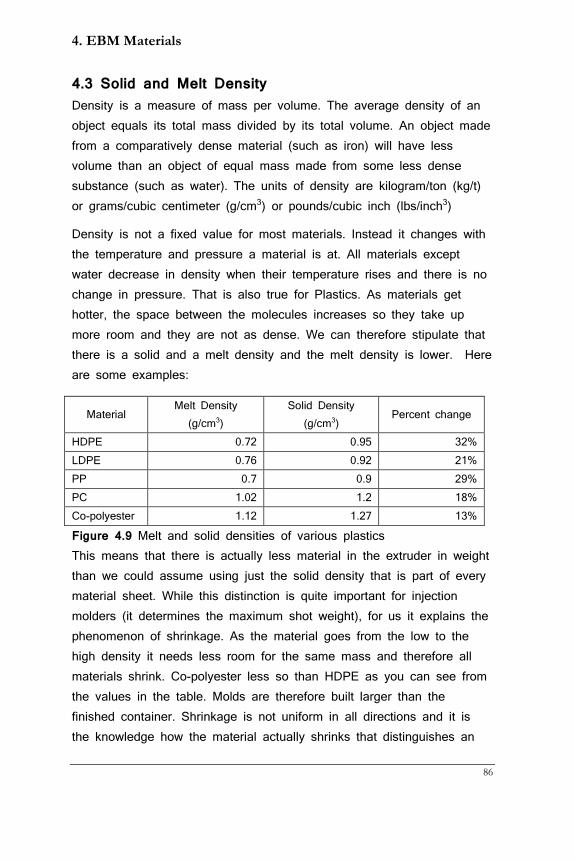
4. EBM Materials
86
4.3 Solid and Melt Density Density is a measure of mass per volume. The average density of an object equals its total mass divided by its total volume. An object made from a comparatively dense material (such as iron) will have less volume than an object of equal mass made from some less dense substance (such as water). The units of density are kilogram/ton (kg/t) or grams/cubic centimeter (g/cm3) or pounds/cubic inch (lbs/inch3)
Density is not a fixed value for most materials. Instead it changes with the temperature and pressure a material is at. All materials except water decrease in density when their temperature rises and there is no change in pressure. That is also true for Plastics. As materials get hotter, the space between the molecules increases so they take up more room and they are not as dense. We can therefore stipulate that there is a solid and a melt density and the melt density is lower. Here are some examples:
Figure 4.9 Melt and solid densities of various plastics This means that there is actually less material in the extruder in weight than we could assume using just the solid density that is part of every material sheet. While this distinction is quite important for injection molders (it determines the maximum shot weight), for us it explains the phenomenon of shrinkage. As the material goes from the low to the high density it needs less room for the same mass and therefore all materials shrink. Co-polyester less so than HDPE as you can see from the values in the table. Molds are therefore built larger than the finished container. Shrinkage is not uniform in all directions and it is the knowledge how the material actually shrinks that distinguishes an
Material Melt Density
(g/cm3) Solid Density
(g/cm3) Percent change
HDPE 0.72 0.95 32% LDPE 0.76 0.92 21% PP 0.7 0.9 29% PC 1.02 1.2 18% Co-polyester 1.12 1.27 13%
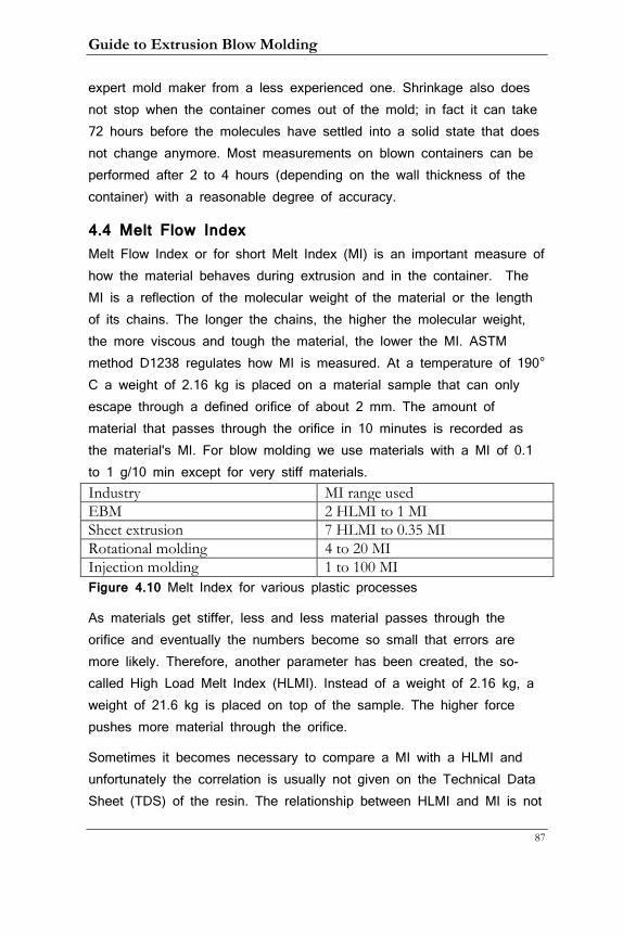
Guide to Extrusion Blow Molding
87
expert mold maker from a less experienced one. Shrinkage also does not stop when the container comes out of the mold; in fact it can take 72 hours before the molecules have settled into a solid state that does not change anymore. Most measurements on blown containers can be performed after 2 to 4 hours (depending on the wall thickness of the container) with a reasonable degree of accuracy.
4.4 Melt Flow Index Melt Flow Index or for short Melt Index (MI) is an important measure of how the material behaves during extrusion and in the container. The MI is a reflection of the molecular weight of the material or the length of its chains. The longer the chains, the higher the molecular weight, the more viscous and tough the material, the lower the MI. ASTM method D1238 regulates how MI is measured. At a temperature of 190° C a weight of 2.16 kg is placed on a material sample that can only escape through a defined orifice of about 2 mm. The amount of material that passes through the orifice in 10 minutes is recorded as the material's MI. For blow molding we use materials with a MI of 0.1 to 1 g/10 min except for very stiff materials. Industry MI range used EBM 2 HLMI to 1 MI Sheet extrusion 7 HLMI to 0.35 MI Rotational molding 4 to 20 MI Injection molding 1 to 100 MI Figure 4.10 Melt Index for various plastic processes
As materials get stiffer, less and less material passes through the orifice and eventually the numbers become so small that errors are more likely. Therefore, another parameter has been created, the so-called High Load Melt Index (HLMI). Instead of a weight of 2.16 kg, a weight of 21.6 kg is placed on top of the sample. The higher force pushes more material through the orifice.
Sometimes it becomes necessary to compare a MI with a HLMI and unfortunately the correlation is usually not given on the Technical Data Sheet (TDS) of the resin. The relationship between HLMI and MI is not
4. EBM Materials
88
linear as placing a higher weight on the sample moves the point in the stress/strain curve of the material to a different location. And of course, as with all plastic curves, this one is not a straight line but a curve of some sort. Molecular weight distribution is a measure of how the material chains are cross-linked and comes into play here. A very ballpark number to get an idea of the relationship between HLMI and MI would be 100. A resin with a MI of 0.1 would have a HLMI of around 10. Resins with a broad molecular distribution might have this relation in the 115 to 120 range, while resins with a narrow distribution would fare around 85 to 90. So this relationship can also be used to assess the molecular weight distribution of a resin.
The MI determines many process characteristics of a resin and processors should pay attention to it especially when they encounter an unusual problem. It is a good idea to have a Technical Data Sheet (TDS) of the material you are running handy during the production run. Most can be accessed on the Internet on the sites of the resin manufacturers. Materials with HLMI numbers as low as 3 are used for high-performance applications like jerry-cans and 55-gallon drums. Some may be available only as powders and need special material handling equipment and longer extruders.
4.5 Viscosity and Shear Viscosity is resistance to flow. A high-viscosity liquid has a high resistance to flow like molasses. A low-viscosity liquid has a low resistance to flow like water. In plastics viscosity depends on the length and shape of the molecules. Short, streamlined molecules have low viscosity. Long, complex, and branched molecules offer more resistance. Viscosity is of course inversely related to MI, i.e. a low MI signifies high viscosity. Viscosity is also related to process conditions, mainly shear temperature. Intuitively, we understand that the more we heat something up (except for burning it) the easier it flows and that is also true for plastics. Since all plastics have a temperature range in which they can be processed the operator has some leeway in choosing which temperature to set. However, it should be understood that the
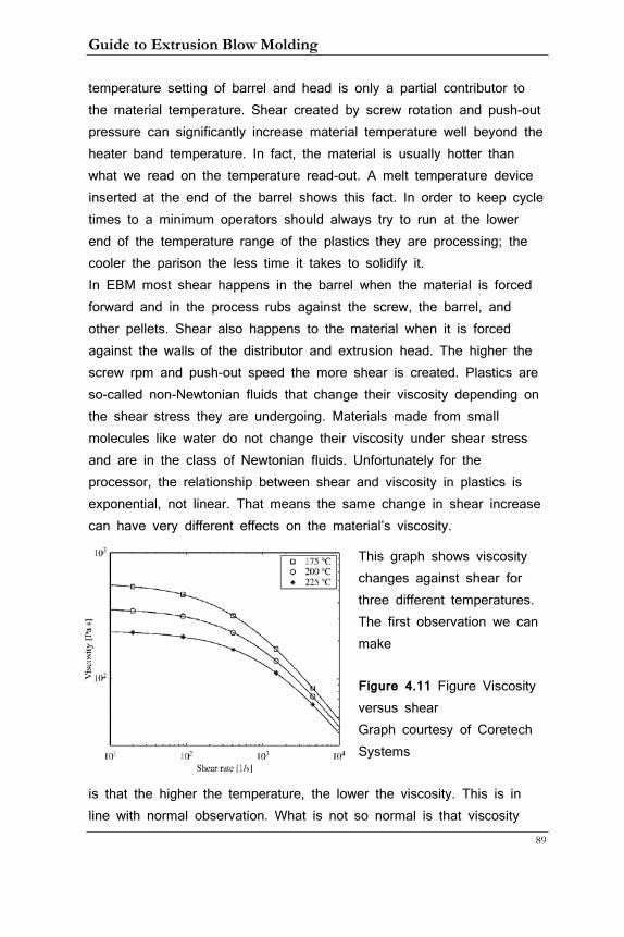
Guide to Extrusion Blow Molding
89
temperature setting of barrel and head is only a partial contributor to the material temperature. Shear created by screw rotation and push-out pressure can significantly increase material temperature well beyond the heater band temperature. In fact, the material is usually hotter than what we read on the temperature read-out. A melt temperature device inserted at the end of the barrel shows this fact. In order to keep cycle times to a minimum operators should always try to run at the lower end of the temperature range of the plastics they are processing; the cooler the parison the less time it takes to solidify it. In EBM most shear happens in the barrel when the material is forced forward and in the process rubs against the screw, the barrel, and other pellets. Shear also happens to the material when it is forced against the walls of the distributor and extrusion head. The higher the screw rpm and push-out speed the more shear is created. Plastics are so-called non-Newtonian fluids that change their viscosity depending on the shear stress they are undergoing. Materials made from small molecules like water do not change their viscosity under shear stress and are in the class of Newtonian fluids. Unfortunately for the processor, the relationship between shear and viscosity in plastics is exponential, not linear. That means the same change in shear increase can have very different effects on the material’s viscosity.
This graph shows viscosity changes against shear for three different temperatures. The first observation we can make
Figure 4.11 Figure Viscosity versus shear Graph courtesy of Coretech Systems
is that the higher the temperature, the lower the viscosity. This is in line with normal observation. What is not so normal is that viscosity
4. EBM Materials
90
does not change much from between 101 to 102 but then starts to accelerate into a steep decline. For the processor this means that under low shear conditions little changes but rapid changes in parison behavior can occur with higher shear stress. (Practical application of this in chapter 6)
4.7 The Future of Plastics
The majority of plastics uses petroleum products as feedstock. This however is done not out of necessity but rather because presently it is the most cost-efficient way of making them. There are only a few elements needed and they can (and have been) polymerized from other sources. I can mention a number of bio-resins with unique structures that are made from corn or sugar cane. The usage of agricultural land to make plastics (and ethanol as gasoline replacement) has been criticized though as food prices have risen in recent years causing wide-spread misery for the poorest of consumers. A more promising approach seems to me to make materials identical to plastics but use remains of food processing as feedstock. Potato and orange peels for example contain the same elements as HDPE or PET and in fact the Pepsi-Cola company is already working on a pilot plant that uses scraps from Pepsi’s food business other than soft drinks as raw material. This is encouraging and we can expect more initiatives like this one to come forth in the coming years as petroleum products will be harder to extract and invariably increase in price.
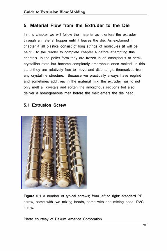
Guide to Extrusion Blow Molding
91
5. Material Flow from the Extruder to the Die
In this chapter we will follow the material as it enters the extruder through a material hopper until it leaves the die. As explained in chapter 4 all plastics consist of long strings of molecules (it will be helpful to the reader to complete chapter 4 before attempting this chapter). In the pellet form they are frozen in an amorphous or semi-crystalline state but become completely amorphous once melted. In this state they are relatively free to move and disentangle themselves from any crystalline structure. Because we practically always have regrind and sometimes additives in the material mix, the extruder has to not only melt all crystals and soften the amorphous sections but also deliver a homogeneous melt before the melt enters the die head.
5.1 Extrusion Screw
Figure 5.1 A number of typical screws; from left to right: standard PE screw, same with two mixing heads, same with one mixing head, PVC screw.
Photo courtesy of Bekum America Corporation
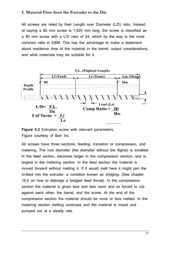
5. Material Flow from the Extruder to the Die
92
All screws are rated by their Length over Diameter (L/D) ratio. Instead of saying a 80 mm screw is 1,920 mm long, the screw is classified as a 80 mm screw with a L/D ratio of 24, which by the way is the most common ratio in EBM. This has the advantage to make a statement about residence time of the material in the barrel, output considerations, and what materials may be suitable for it.
Figure 5.2 Extrusion screw with relevant parameters. Figure courtesy of Barr Inc.
All screws have three sections: feeding, transition or compression, and metering. The root diameter (the diameter without the flights) is smallest in the feed section, becomes larger in the compression section, and is largest in the metering section. In the feed section the material is moved forward without melting it. If it would melt here it might jam the in-feed into the extruder, a condition known as bridging. (See chapter 16.6 on how to dislodge a bridged feed throat). In the compression section the material is given less and less room and so forced to rub against each other, the barrel, and the screw. At the end of the compression section the material should be more or less melted. In the metering section melting continues and the material is mixed and pumped out at a steady rate.
Guide to Extrusion Blow Molding
93
Figure 5.3 Types of screws used in extrusion blow molding Diagram courtesy of Barr Inc. The compression ratio is the ratio of the flight height at the feed section and the height at the metering section. This tells how much the material is forced to shear and is a material-specific parameter. The length of each section (in parts of the L/D ratio) is also material-specific and by no means equal. Here is a table showing some of these parameters for different materials:
Dimension PVC Polystyrene LDPE HDPE Nylon Diameter (mm) 120 120 120 120 120 L/D ratio 20 20 20 20 20 Feed (mm) 360 720 600 960 1800 Compression (mm)
2040 480 1200 480 120
Metering (mm) 0 1200 600 960 480 Metering height (mm)
5 3.5 3.2 3.9 3.2
Feed height (mm)
15.2 15.2 15.2 16.5 15.2
Compression ratio
3 4.3 4.8 4.2 4.8
Figure 5.4 Selected screw parameters for various materials
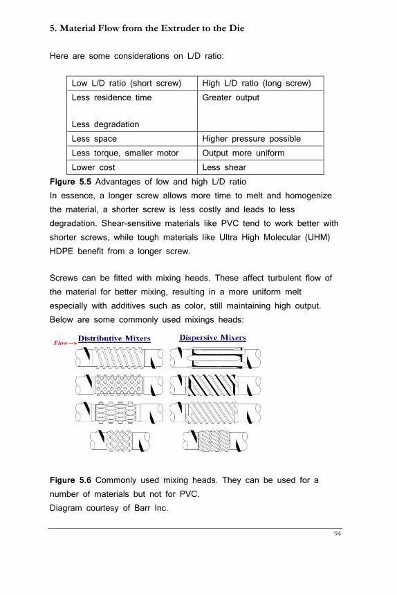
5. Material Flow from the Extruder to the Die
94
Here are some considerations on L/D ratio:
Low L/D ratio (short screw) High L/D ratio (long screw) Less residence time
Less degradation
Greater output
Less space Higher pressure possible Less torque, smaller motor Output more uniform Lower cost Less shear
Figure 5.5 Advantages of low and high L/D ratio In essence, a longer screw allows more time to melt and homogenize the material, a shorter screw is less costly and leads to less degradation. Shear-sensitive materials like PVC tend to work better with shorter screws, while tough materials like Ultra High Molecular (UHM) HDPE benefit from a longer screw.
Screws can be fitted with mixing heads. These affect turbulent flow of the material for better mixing, resulting in a more uniform melt especially with additives such as color, still maintaining high output. Below are some commonly used mixings heads:
Figure 5.6 Commonly used mixing heads. They can be used for a number of materials but not for PVC. Diagram courtesy of Barr Inc.
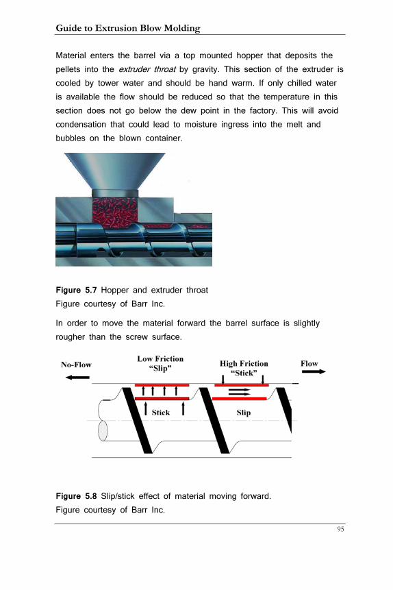
Guide to Extrusion Blow Molding
95
Material enters the barrel via a top mounted hopper that deposits the pellets into the extruder throat by gravity. This section of the extruder is cooled by tower water and should be hand warm. If only chilled water is available the flow should be reduced so that the temperature in this section does not go below the dew point in the factory. This will avoid condensation that could lead to moisture ingress into the melt and bubbles on the blown container.
Figure 5.7 Hopper and extruder throat Figure courtesy of Barr Inc.
In order to move the material forward the barrel surface is slightly rougher than the screw surface.
Figure 5.8 Slip/stick effect of material moving forward. Figure courtesy of Barr Inc.
5. Material Flow from the Extruder to the Die
96
The screw then slips under the resin pellets whereas the outer resin layer sticks slightly to the barrel. This way the material moves forward. When burned material accumulates on the screw it may become sticky and the forward movement of the material is reduced. This results in lower output and eventually the screw has to be cleaned. It this therefore a good idea to include screw rpm on the setup sheet so that a historical record exists that can be compared to the same job that may happen months later. This will tell if a reduction in screw output has happened.
Screw technology has greatly advanced over the last 20 years and modern screws are able to process much higher outputs at low shear rates. Barrier, Energy Transfer, and Variable Barrier Energy Transfer screws use dual-flow channels where melted and un-melted materials mix at much greater speed. While a more complete review of screw
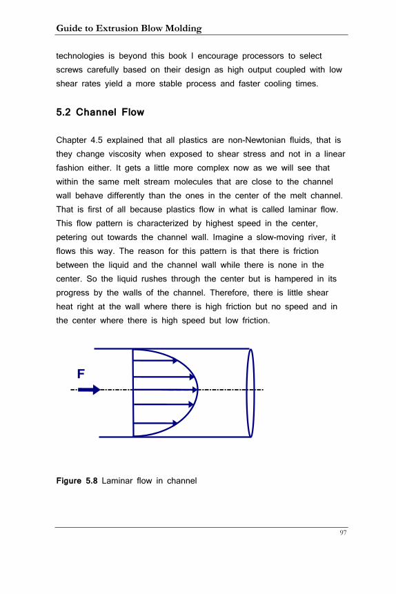
Guide to Extrusion Blow Molding
97
technologies is beyond this book I encourage processors to select screws carefully based on their design as high output coupled with low shear rates yield a more stable process and faster cooling times.
5.2 Channel Flow
Chapter 4.5 explained that all plastics are non-Newtonian fluids, that is they change viscosity when exposed to shear stress and not in a linear fashion either. It gets a little more complex now as we will see that within the same melt stream molecules that are close to the channel wall behave differently than the ones in the center of the melt channel. That is first of all because plastics flow in what is called laminar flow. This flow pattern is characterized by highest speed in the center, petering out towards the channel wall. Imagine a slow-moving river, it flows this way. The reason for this pattern is that there is friction between the liquid and the channel wall while there is none in the center. So the liquid rushes through the center but is hampered in its progress by the walls of the channel. Therefore, there is little shear heat right at the wall where there is high friction but no speed and in the center where there is high speed but low friction.
Figure 5.8 Laminar flow in channel
F
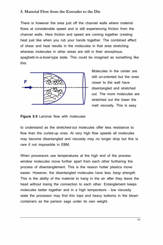
5. Material Flow from the Extruder to the Die
98
There is however the area just off the channel walls where material flows at considerable speed and is still experiencing friction from the channel walls. Here friction and speed are coming together creating heat just like when you rub your hands together. The combined effect of shear and heat results in the molecules in that area stretching whereas molecules in other areas are still in their amorphous, spaghetti-in-a-bowl-type state. This could be imagined as something like this:
Molecules in the center are still un-oriented but the ones closer to the wall have disentangled and stretched out. The more molecules are stretched out the lower the melt viscosity. This is easy
Figure 5.9 Laminar flow with molecules
to understand as the stretched-out molecules offer less resistance to flow than the curled-up ones. At very high flow speeds all molecules may become disentangled and viscosity may no longer drop but this is rare if not impossible in EBM.
When processors use temperatures at the high end of the process window molecules move further apart from each other furthering the process of disentanglement. This is the reason hotter plastics move easier. However, the disentangled molecules have less hang strength. This is the ability of the material to hang in the air after they leave the head without losing the connection to each other. Entanglement keeps molecules better together and in a high temperature – low viscosity state the processor may find thin tops and heavy bottoms in the blown containers as the parison sags under its own weight.
F
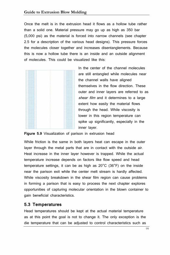
Guide to Extrusion Blow Molding
99
Once the melt is in the extrusion head it flows as a hollow tube rather than a solid one. Material pressure may go up as high as 350 bar (5,000 psi) as the material is forced into narrow channels (see chapter 2.5 for a description of the various head designs). This pressure forces the molecules closer together and increases disentanglements. Because this is now a hollow tube there is an inside and an outside alignment of molecules. This could be visualized like this:
In the center of the channel molecules are still entangled while molecules near the channel walls have aligned themselves in the flow direction. These outer and inner layers are referred to as shear film and it determines to a large extent how easily the material flows through the head. While viscosity is lower in this region temperature can spike up significantly, especially in the inner layer.
Figure 5.9 Visualization of parison in extrusion head
While friction is the same in both layers heat can escape in the outer layer through the metal parts that are in contact with the outside air. Heat increase in the inner layer however is trapped. While the actual temperature increase depends on factors like flow speed and head temperature settings, it can be as high as 20°C (36°F) on the inside near the parison exit while the center melt stream is hardly affected. While viscosity breakdown in the shear film region can cause problems in forming a parison that is easy to process the next chapter explores opportunities of capturing molecular orientation in the blown container to gain beneficial characteristics.
5.3 Temperatures Head temperatures should be kept at the actual material temperature as at this point the goal is not to change it. The only exception is the die temperature that can be adjusted to control characteristics such as
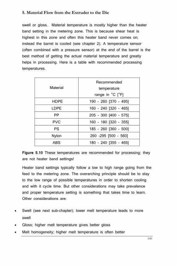
5. Material Flow from the Extruder to the Die
100
swell or gloss. Material temperature is mostly higher than the heater band setting in the metering zone. This is because shear heat is highest in this zone and often this heater band never comes on; instead the barrel is cooled (see chapter 2). A temperature sensor (often combined with a pressure sensor) at the end of the barrel is the best method of getting the actual material temperature and greatly helps in processing. Here is a table with recommended processing temperatures.
Figure 5.10 These temperatures are recommended for processing; they are not heater band settings!
Heater band settings typically follow a low to high range going from the feed to the metering zone. The overarching principle should be to stay to the low range of possible temperatures in order to shorten cooling and with it cycle time. But other considerations may take prevalence and proper temperature setting is something that takes time to learn. Other considerations are:
• Swell (see next sub-chapter); lower melt temperature leads to more
swell
• Gloss; higher melt temperature gives better gloss
• Melt homogeneity; higher melt temperature is often better
Material Recommended temperature
range in °C [°F]
HDPE 190 - 260 [370 - 495]
LDPE 160 - 240 [320 - 465]
PP 205 - 300 [400 - 575]
PVC 160 - 180 [320 - 355]
PS 185 - 260 [360 - 500]
Nylon 260 -295 [500 - 560]
ABS 180 - 240 [355 - 465]
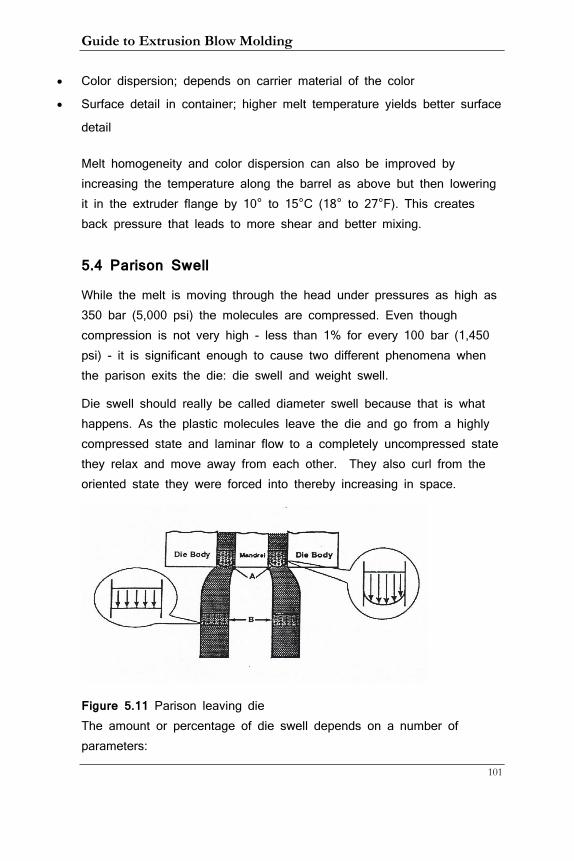
Guide to Extrusion Blow Molding
101
• Color dispersion; depends on carrier material of the color
• Surface detail in container; higher melt temperature yields better surface
detail
Melt homogeneity and color dispersion can also be improved by increasing the temperature along the barrel as above but then lowering it in the extruder flange by 10° to 15°C (18° to 27°F). This creates back pressure that leads to more shear and better mixing.
5.4 Parison Swell
While the melt is moving through the head under pressures as high as 350 bar (5,000 psi) the molecules are compressed. Even though compression is not very high - less than 1% for every 100 bar (1,450 psi) - it is significant enough to cause two different phenomena when the parison exits the die: die swell and weight swell.
Die swell should really be called diameter swell because that is what happens. As the plastic molecules leave the die and go from a highly compressed state and laminar flow to a completely uncompressed state they relax and move away from each other. They also curl from the oriented state they were forced into thereby increasing in space.
Figure 5.11 Parison leaving die The amount or percentage of die swell depends on a number of parameters:
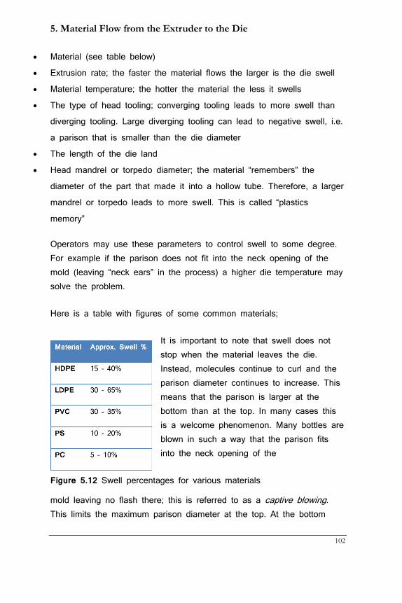
5. Material Flow from the Extruder to the Die
102
• Material (see table below)
• Extrusion rate; the faster the material flows the larger is the die swell
• Material temperature; the hotter the material the less it swells
• The type of head tooling; converging tooling leads to more swell than
diverging tooling. Large diverging tooling can lead to negative swell, i.e.
a parison that is smaller than the die diameter
• The length of the die land
• Head mandrel or torpedo diameter; the material “remembers” the
diameter of the part that made it into a hollow tube. Therefore, a larger
mandrel or torpedo leads to more swell. This is called “plastics
memory”
Operators may use these parameters to control swell to some degree. For example if the parison does not fit into the neck opening of the mold (leaving “neck ears” in the process) a higher die temperature may solve the problem.
Here is a table with figures of some common materials;
It is important to note that swell does not stop when the material leaves the die. Instead, molecules continue to curl and the parison diameter continues to increase. This means that the parison is larger at the bottom than at the top. In many cases this is a welcome phenomenon. Many bottles are blown in such a way that the parison fits into the neck opening of the
Figure 5.12 Swell percentages for various materials
mold leaving no flash there; this is referred to as a captive blowing. This limits the maximum parison diameter at the top. At the bottom
Guide to Extrusion Blow Molding
103
however a larger diameter is beneficial as this means that bottom corners are blown thicker. More on that in chapter 6. While the parison swells in diameter it also becomes thicker. This is called weight swell. This behavior is quite dramatic with the parison often doubling in thickness as it leaves the die. This also slows down the speed at which the parison extrudes. Weight swell is caused by the same behavior that causes diameter swell: the molecules that are stretched out inside the head curl in both the hoop and the flow direction. Both diameter and weight swell cause the parison to become a very different shape than what could be expected from the dimensions of the pin and die through which it flows.
People that design dies and pins for a particular application have to consider these relationships, working backwards from the container shape. Often experience trumps theoretical knowledge. That is because of the great range of diameter swell especially for HDPE and LDPE. It is advisable to any company to keep a log of bottle and die/pin dimensions on file to make use of previous experience. Too often this information resides in the head of one person that is then in a position of job security no matter what the actual job performance is!

5. Material Flow from the Extruder to the Die
104
Guide to Extrusion Blow Molding
105
6. Blowing a Container
After the parison leaves the head it is clamped between two mold halves and inflated. While this process is universal for all EBM machines there are considerable differences in how this is accomplished. Before we go into a description for the different machines let’s review common characteristics of blowing behavior.
6.1 Inflating the Parison
All molecules in the parison move at the same speed and are in their amorphous, un-oriented state in the center of the parison while the outer layers are aligned to the melt direction. When the air inflates them the molecules orient themselves additionally to some degree in the hoop direction. This orientation is dependent on
• The melt temperature
• The mold temperature
• The degree of stretch, called the stretch ratio or blow ratio
Cooler melt temperature fosters orientation as the molecules are less likely to get back to their amorphous state. Cooler mold temperature freezes the orientation state at least in the outer parts of the container wall. Thicker walls may have highly oriented molecules in the outer layers but more or less amorphous ones in the inner part of the wall. Molecules that are stretched the furthest orient more than parts that are not stretched as much. Orientation is beneficial to container strength even though wall thickness is still the most important factor.
This stretch ratio is not the same for all parts of the parison even in round bottles and certainly not in oblong ones. As can be seen on the next page the different length of the arrows indicates how much the parison has to stretch to reach the wall of the mold. Especially noteworthy is the high stretch ratio into the bottom corner. Because the
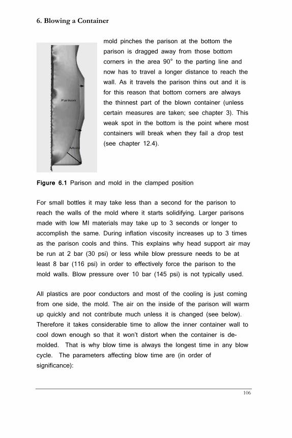
6. Blowing a Container
106
mold pinches the parison at the bottom the parison is dragged away from those bottom corners in the area 90° to the parting line and now has to travel a longer distance to reach the wall. As it travels the parison thins out and it is for this reason that bottom corners are always the thinnest part of the blown container (unless certain measures are taken; see chapter 3). This weak spot in the bottom is the point where most containers will break when they fail a drop test (see chapter 12.4).
Figure 6.1 Parison and mold in the clamped position
For small bottles it may take less than a second for the parison to reach the walls of the mold where it starts solidifying. Larger parisons made with low MI materials may take up to 3 seconds or longer to accomplish the same. During inflation viscosity increases up to 3 times as the parison cools and thins. This explains why head support air may be run at 2 bar (30 psi) or less while blow pressure needs to be at least 8 bar (116 psi) in order to effectively force the parison to the mold walls. Blow pressure over 10 bar (145 psi) is not typically used.
All plastics are poor conductors and most of the cooling is just coming from one side, the mold. The air on the inside of the parison will warm up quickly and not contribute much unless it is changed (see below). Therefore it takes considerable time to allow the inner container wall to cool down enough so that it won’t distort when the container is de-molded. That is why blow time is always the longest time in any blow cycle. The parameters affecting blow time are (in order of significance):
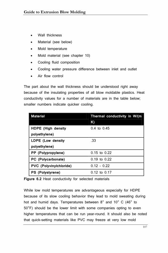
Guide to Extrusion Blow Molding
107
• Wall thickness
• Material (see below)
• Mold temperature
• Mold material (see chapter 10)
• Cooling fluid composition
• Cooling water pressure difference between inlet and outlet
• Air flow control
The part about the wall thickness should be understood right away because of the insulating properties of all blow moldable plastics. Heat conductivity values for a number of materials are in the table below; smaller numbers indicate quicker cooling.
Material Thermal conductivity in W/(m K)
HDPE (High density polyethylene)
0.4 to 0.45
LDPE (Low density polyethylene)
.33
PP (Polypropylene) 0.15 to 0.22
PC (Polycarbonate) 0.19 to 0.22
PVC (Polyvinylchloride) 0.12 – 0.22
PS (Polystyrene) 0.12 to 0.17
Figure 6.2 Heat conductivity for selected materials
While low mold temperatures are advantageous especially for HDPE because of its slow cooling behavior they lead to mold sweating during hot and humid days. Temperatures between 8° and 10° C (46° to 50°F) should be the lower limit with some companies opting to even higher temperatures that can be run year-round. It should also be noted that quick-setting materials like PVC may freeze at very low mold
6. Blowing a Container
108
temperatures before the container is fully formed (more about cooling recommendations in chapter 13.11).
Mold material also plays a role. Aluminum is best, followed by beryllium copper, steel, and Stainless Steel. Molds for bottles up to 20 l usually consist of aluminum bodies with beryllium copper neck and bottom inserts. Larger molds are often cast-iron.
Water is the best cooling fluid. Adding a large percentage of anti-freeze diminishes cooling capability and puts an additional load on the process pumps because of the greater viscosity of the water/anti-freeze mixture.
Water pressure at the machine inlet should be a minimum of 3 bar (42 psi) with an optimum of 5 bar (70 psi) higher than pressure on the outlet to get turbulent flow inside the molds. More on that in chapter 13.1.
Most accumulator head machines are equipped with the ability to vent the parison during blow and refill it with fresh and cooler air. This feature is often called huff and puff and is very useful for containers with walls thicker than 2 mm. Another way of achieving similar results is to blow at full pressure for a few seconds and then vent the parison partially and continuously. This can be accomplished with a secondary venting valve that allows only a small portion of air to escape thereby keeping a lower pressure inside the parison that is still high enough to force the material against the mold walls. Other methods to speed up solidification of the parison are cooling the blow air or injecting CO2 into it. While these can decrease blow time by up to 25% the added cost and maintenance they incur has many companies shy away from them.
As can be seen there are a number of ways to reduce blow times and I will explore these in more details in chapters 10 and 13.1.
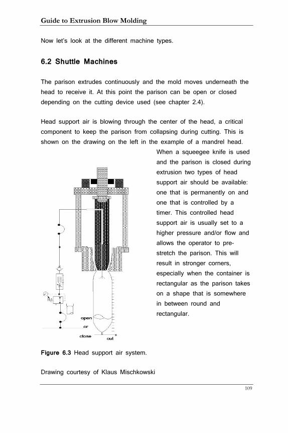
Guide to Extrusion Blow Molding
109
Now let’s look at the different machine types.
6.2 Shuttle Machines
The parison extrudes continuously and the mold moves underneath the head to receive it. At this point the parison can be open or closed depending on the cutting device used (see chapter 2.4).
Head support air is blowing through the center of the head, a critical component to keep the parison from collapsing during cutting. This is shown on the drawing on the left in the example of a mandrel head.
When a squeegee knife is used and the parison is closed during extrusion two types of head support air should be available: one that is permanently on and one that is controlled by a timer. This controlled head support air is usually set to a higher pressure and/or flow and allows the operator to pre-stretch the parison. This will result in stronger corners, especially when the container is rectangular as the parison takes on a shape that is somewhere in between round and rectangular.
Figure 6.3 Head support air system.
Drawing courtesy of Klaus Mischkowski
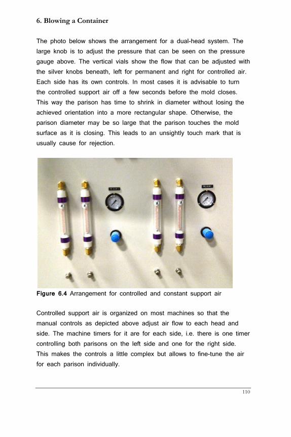
6. Blowing a Container
110
The photo below shows the arrangement for a dual-head system. The large knob is to adjust the pressure that can be seen on the pressure gauge above. The vertical vials show the flow that can be adjusted with the silver knobs beneath, left for permanent and right for controlled air. Each side has its own controls. In most cases it is advisable to turn the controlled support air off a few seconds before the mold closes. This way the parison has time to shrink in diameter without losing the achieved orientation into a more rectangular shape. Otherwise, the parison diameter may be so large that the parison touches the mold surface as it is closing. This leads to an unsightly touch mark that is usually cause for rejection.
Figure 6.4 Arrangement for controlled and constant support air
Controlled support air is organized on most machines so that the manual controls as depicted above adjust air flow to each head and side. The machine timers for it are for each side, i.e. there is one timer controlling both parisons on the left side and one for the right side. This makes the controls a little complex but allows to fine-tune the air for each parison individually.
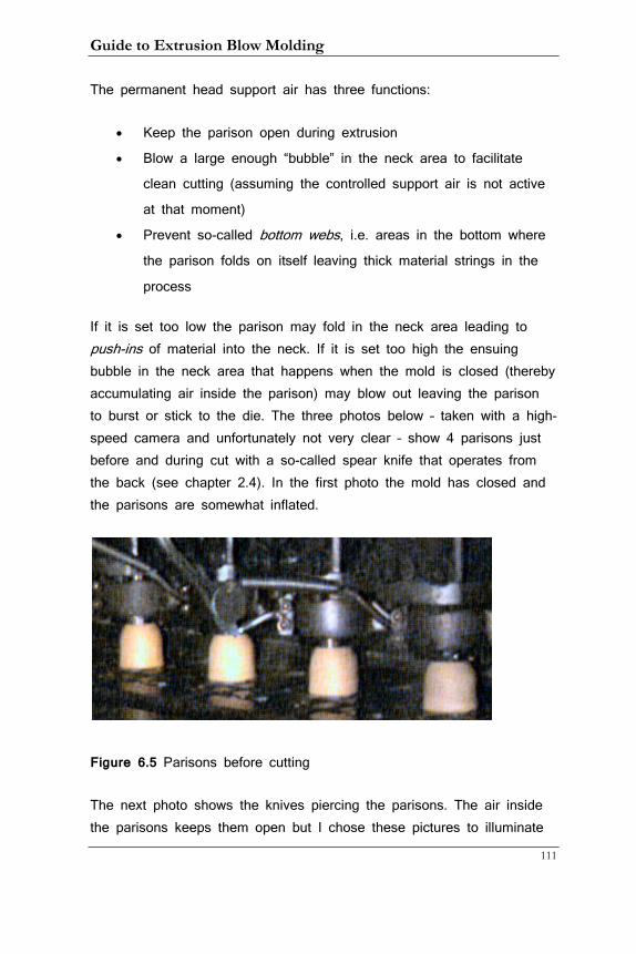
Guide to Extrusion Blow Molding
111
The permanent head support air has three functions:
• Keep the parison open during extrusion
• Blow a large enough “bubble” in the neck area to facilitate
clean cutting (assuming the controlled support air is not active
at that moment)
• Prevent so-called bottom webs, i.e. areas in the bottom where
the parison folds on itself leaving thick material strings in the
process
If it is set too low the parison may fold in the neck area leading to push-ins of material into the neck. If it is set too high the ensuing bubble in the neck area that happens when the mold is closed (thereby accumulating air inside the parison) may blow out leaving the parison to burst or stick to the die. The three photos below – taken with a high-speed camera and unfortunately not very clear – show 4 parisons just before and during cut with a so-called spear knife that operates from the back (see chapter 2.4). In the first photo the mold has closed and the parisons are somewhat inflated.
Figure 6.5 Parisons before cutting
The next photo shows the knives piercing the parisons. The air inside the parisons keeps them open but I chose these pictures to illuminate
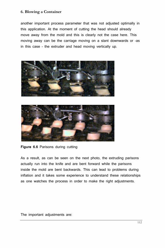
6. Blowing a Container
112
another important process parameter that was not adjusted optimally in this application. At the moment of cutting the head should already move away from the mold and this is clearly not the case here. This moving away can be the carriage moving on a slant downwards or –as in this case – the extruder and head moving vertically up.
Figure 6.6 Parisons during cutting
As a result, as can be seen on the next photo, the extruding parisons actually run into the knife and are bent forward while the parisons inside the mold are bent backwards. This can lead to problems during inflation and it takes some experience to understand these relationships as one watches the process in order to make the right adjustments.
The important adjustments are:
Guide to Extrusion Blow Molding
113
• Delay cutting
• Delay carriage down (or back)
• Delay extruder bobbing (for horizontal machines only)
The longer the cutting is delayed the bigger the bubble that can be created in conjunction with permanent head support air. On slanted machines the carriage should be on its way downwards before the cutting starts but the timers do not always reflect that, i.e. the machine may run with delay carriage timer that is set shorter than the delay cutting timer. That is because there may be a longer delay before the end of the timer and the actual movement of the carriage compared with that of the knife. The timers for either side may also be slightly different because the carriages may not respond to the actuating signal with the same delay. While the delay cutting and carriage down timers start when the mold is closed the delay extruder bobbing timer starts when the mold starts to close. The bobbing movement is not very fast and thus needs to be started earlier to be able to get the head out of the way during cutting.
When a squeegee or spear knife is used there is also a cutting timer. When it times out it energizes the knife to go back. Sometimes it is started at the same time as the delay cutting timer, on other machines when the delay cutting timer has timed out. In either case it has to be adjusted to bring the knife back as soon as the forward movement is completed. Only experimenting with it will give the right adjustment. Flow controls directly on the knife allow adjusting the speed of the knife; it should be fast without banging into the end stops as this will lead to early wear.
To sum up this part, the right combination of head support air, both permanent and controlled, the cutting timer(s), delay carriage back, and delay extruder bobbing (with horizontal machines) will yield a parison cut that leaves the cut parison open without folding and so ensure that the blow pin can enter the neck of the mold smoothly. In chapter 3 you
6. Blowing a Container
114
can read about how the programmer can be used to facilitate this as well.
Once the parison is cut the mold moves underneath the blow pin station and the blow pin delay down timer starts. It is usually set to 0 but with some PP containers it can be beneficial to start blowing before the blow pin moves. Many machines have two blow pressures that can be activated with separate timers. The first pressure is set to just 2 or 3 bar (30 to 45 psi) or below and is used to keep the parison open as the blow pin descends and reduce the noise level that can be quite high when standard blow pressure at around 8 bar (90 psi) is used for this purpose. In any case, once the blow pin moves blow air needs to come on and be at full pressure when it has entered the mold.
The parison now inflates against the mold walls as described above and solidifies. Blowing time should be chosen to allow de-molding of the container. Exhaust time starts right after blow time has time out. During exhaust the air pressure inside the container has to be reduced to or close to atmospheric pressure so the container does not rupture. If it is set too small, the container bottom may be pushed out and stay that way. This is the so-called rocker bottom that can also occur when the bottom is too hot at de-molding time and then shrinks out. Air exhaust is facilitated by a quick exhaust valve. It is mounted close to the blow pin(s) and allows air to escape right there instead of having to flow back through the blow valve. This saves time and quick exhaust valves can also be mounted to cylinder like the cutting cylinder when fast return movements are needed. Here are the points to watch out for when containers are de-molded:
• Container cannot distort especially when it is de-flashed
automatically
• Flash has to come off without hanging up
• Container walls cannot fall in (panel sink) • Neck has to be round within specifications (see chapter 10)
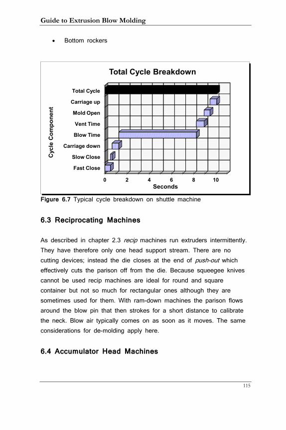
Guide to Extrusion Blow Molding
115
• Bottom rockers
Figure 6.7 Typical cycle breakdown on shuttle machine
6.3 Reciprocating Machines
As described in chapter 2.3 recip machines run extruders intermittently. They have therefore only one head support stream. There are no cutting devices; instead the die closes at the end of push-out which effectively cuts the parison off from the die. Because squeegee knives cannot be used recip machines are ideal for round and square container but not so much for rectangular ones although they are sometimes used for them. With ram-down machines the parison flows around the blow pin that then strokes for a short distance to calibrate the neck. Blow air typically comes on as soon as it moves. The same considerations for de-molding apply here.
6.4 Accumulator Head Machines
0 2 4 6 8 10
Fast Close
Slow Close
Carriage down
Blow Time
Vent Time
Mold Open
Carriage up
Total Cycle
Seconds
Cyc
le C
ompo
nent
Total Cycle Breakdown
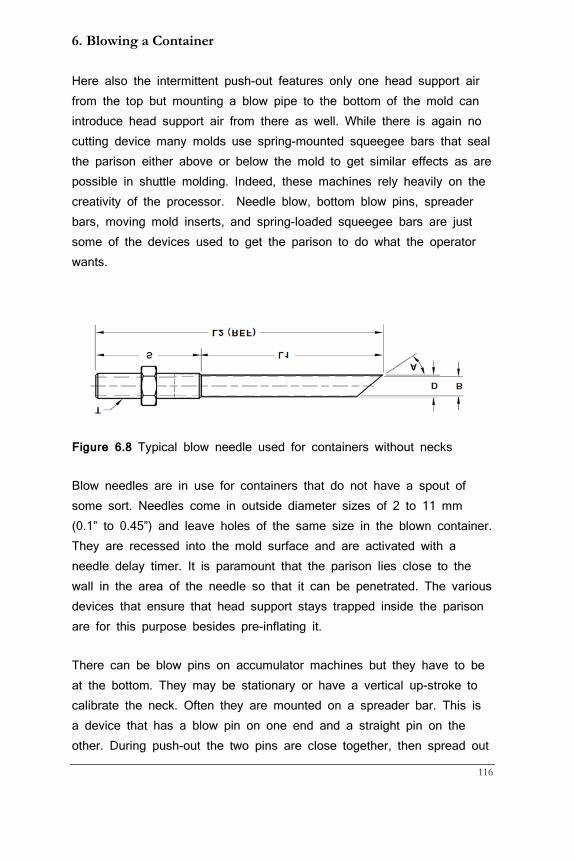
6. Blowing a Container
116
Here also the intermittent push-out features only one head support air from the top but mounting a blow pipe to the bottom of the mold can introduce head support air from there as well. While there is again no cutting device many molds use spring-mounted squeegee bars that seal the parison either above or below the mold to get similar effects as are possible in shuttle molding. Indeed, these machines rely heavily on the creativity of the processor. Needle blow, bottom blow pins, spreader bars, moving mold inserts, and spring-loaded squeegee bars are just some of the devices used to get the parison to do what the operator wants.
Figure 6.8 Typical blow needle used for containers without necks
Blow needles are in use for containers that do not have a spout of some sort. Needles come in outside diameter sizes of 2 to 11 mm (0.1” to 0.45”) and leave holes of the same size in the blown container. They are recessed into the mold surface and are activated with a needle delay timer. It is paramount that the parison lies close to the wall in the area of the needle so that it can be penetrated. The various devices that ensure that head support stays trapped inside the parison are for this purpose besides pre-inflating it.
There can be blow pins on accumulator machines but they have to be at the bottom. They may be stationary or have a vertical up-stroke to calibrate the neck. Often they are mounted on a spreader bar. This is a device that has a blow pin on one end and a straight pin on the other. During push-out the two pins are close together, then spread out
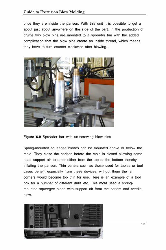
Guide to Extrusion Blow Molding
117
once they are inside the parison. With this unit it is possible to get a spout just about anywhere on the side of the part. In the production of drums two blow pins are mounted to a spreader bar with the added complication that the blow pins create an inside thread, which means they have to turn counter clockwise after blowing.
Figure 6.9 Spreader bar with un-screwing blow pins
Spring-mounted squeegee blades can be mounted above or below the mold. They close the parison before the mold is closed allowing some head support air to enter either from the top or the bottom thereby inflating the parison. Thin panels such as those used for tables or tool cases benefit especially from these devices; without them the far corners would become too thin for use. Here is an example of a tool box for a number of different drills etc. This mold used a spring-mounted squeegee blade with support air from the bottom and needle blow.
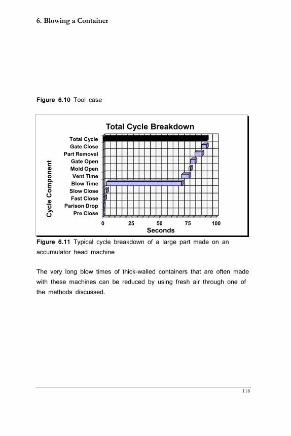
6. Blowing a Container
118
Figure 6.10 Tool case
Figure 6.11 Typical cycle breakdown of a large part made on an accumulator head machine
The very long blow times of thick-walled containers that are often made with these machines can be reduced by using fresh air through one of the methods discussed.
0 25 50 75 100
Pre Close Parison Drop
Fast Close Slow Close Blow Time Vent Time
Mold Open Gate Open
Part Removal Gate Close Total Cycle
Seconds
Cyc
le C
ompo
nent
Total Cycle Breakdown
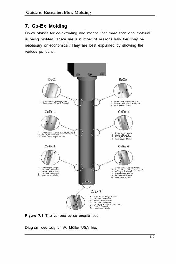
Guide to Extrusion Blow Molding
119
7. Co-Ex Molding Co-ex stands for co-extruding and means that more than one material is being molded. There are a number of reasons why this may be necessary or economical. They are best explained by showing the various parisons.
Figure 7.1 The various co-ex possibilities
Diagram courtesy of W. Müller USA Inc.
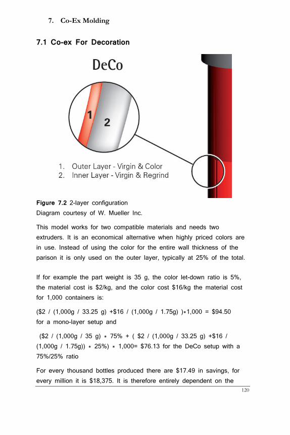
7. Co-Ex Molding
120
7.1 Co-ex For Decoration
Figure 7.2 2-layer configuration Diagram courtesy of W. Mueller Inc.
This model works for two compatible materials and needs two extruders. It is an economical alternative when highly priced colors are in use. Instead of using the color for the entire wall thickness of the parison it is only used on the outer layer, typically at 25% of the total.
If for example the part weight is 35 g, the color let-down ratio is 5%, the material cost is $2/kg, and the color cost $16/kg the material cost for 1,000 containers is:
($2 / (1,000g / 33.25 g) +$16 / (1,000g / 1.75g) )*1,000 = $94.50 for a mono-layer setup and
($2 / (1,000g / 35 g) * 75% + ( $2 / (1,000g / 33.25 g) +$16 / (1,000g / 1.75g)) * 25%) * 1,000= $76.13 for the DeCo setup with a 75%/25% ratio
For every thousand bottles produced there are $17.49 in savings, for every million it is $18,375. It is therefore entirely dependent on the
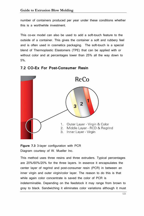
Guide to Extrusion Blow Molding
121
number of containers produced per year under these conditions whether this is a worthwhile investment.
This co-ex model can also be used to add a soft-touch feature to the outside of a container. This gives the container a soft and rubbery feel and is often used in cosmetics packaging. The soft-touch is a special blend of Thermoplastic Elastomers (TPE) that can be applied with or without color and at percentages lower than 25% all the way down to 5%.
7.2 CO-Ex For Post-Consumer Resin
Figure 7.3 3-layer configuration with PCR Diagram courtesy of W. Mueller Inc.
This method uses three resins and three extruders. Typical percentages are 20%/60%/20% for the three layers. In essence it encapsulates the center layer of regrind and post-consumer resin (PCR) in between an inner virgin and outer virgin/color layer. The reason to do this is that while again color concentrate is saved the color of PCR is indeterminable. Depending on the feedstock it may range from brown to gray to black. Sandwiching it eliminates color variations although it must
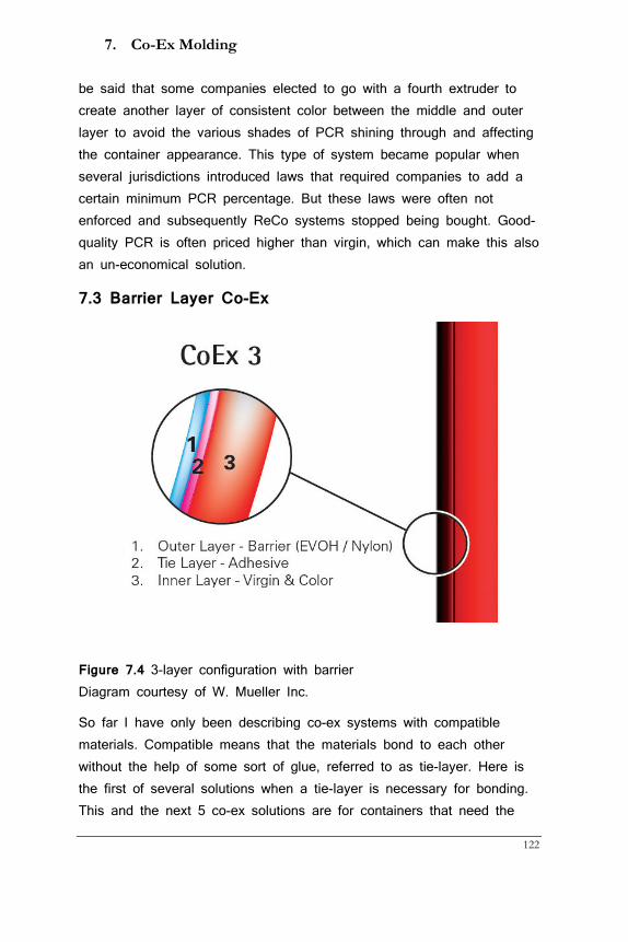
7. Co-Ex Molding
122
be said that some companies elected to go with a fourth extruder to create another layer of consistent color between the middle and outer layer to avoid the various shades of PCR shining through and affecting the container appearance. This type of system became popular when several jurisdictions introduced laws that required companies to add a certain minimum PCR percentage. But these laws were often not enforced and subsequently ReCo systems stopped being bought. Good-quality PCR is often priced higher than virgin, which can make this also an un-economical solution.
7.3 Barrier Layer Co-Ex
Figure 7.4 3-layer configuration with barrier Diagram courtesy of W. Mueller Inc.
So far I have only been describing co-ex systems with compatible materials. Compatible means that the materials bond to each other without the help of some sort of glue, referred to as tie-layer. Here is the first of several solutions when a tie-layer is necessary for bonding. This and the next 5 co-ex solutions are for containers that need the
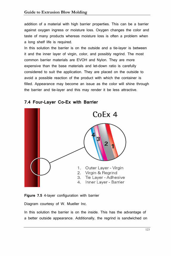
Guide to Extrusion Blow Molding
123
addition of a material with high barrier properties. This can be a barrier against oxygen ingress or moisture loss. Oxygen changes the color and taste of many products whereas moisture loss is often a problem when a long shelf life is required. In this solution the barrier is on the outside and a tie-layer is between it and the inner layer of virgin, color, and possibly regrind. The most common barrier materials are EVOH and Nylon. They are more expensive than the base materials and let-down ratio is carefully considered to suit the application. They are placed on the outside to avoid a possible reaction of the product with which the container is filled. Appearance may become an issue as the color will shine through the barrier and tie-layer and this may render it be less attractive.
7.4 Four-Layer Co-Ex with Barrier
Figure 7.5 4-layer configuration with barrier
Diagram courtesy of W. Mueller Inc.
In this solution the barrier is on the inside. This has the advantage of a better outside appearance. Additionally, the regrind is sandwiched on
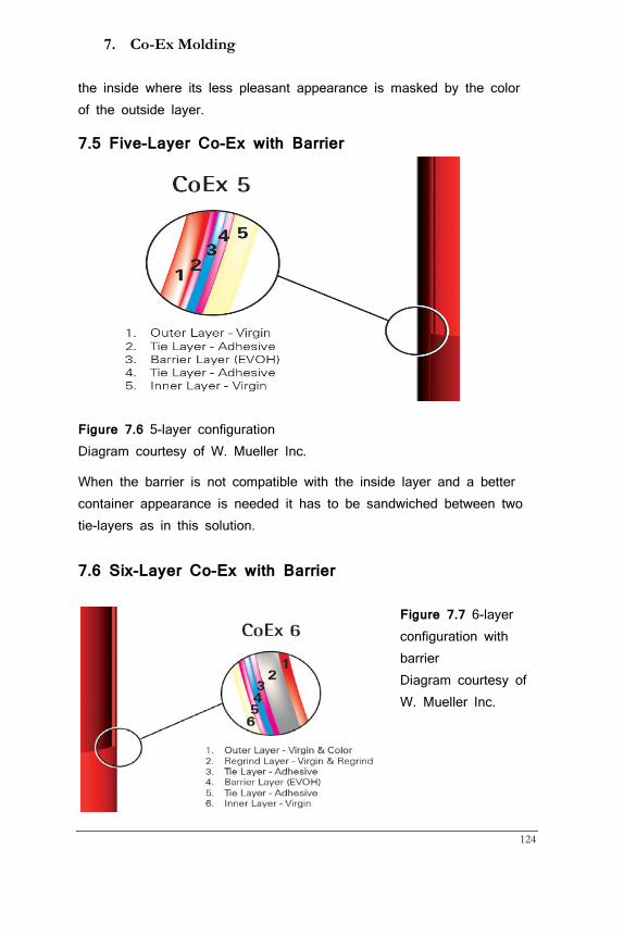
7. Co-Ex Molding
124
the inside where its less pleasant appearance is masked by the color of the outside layer.
7.5 Five-Layer Co-Ex with Barrier
Figure 7.6 5-layer configuration Diagram courtesy of W. Mueller Inc.
When the barrier is not compatible with the inside layer and a better container appearance is needed it has to be sandwiched between two tie-layers as in this solution.
7.6 Six-Layer Co-Ex with Barrier
Figure 7.7 6-layer configuration with barrier Diagram courtesy of W. Mueller Inc.
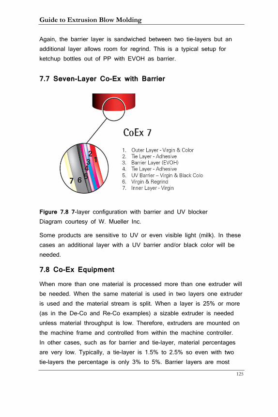
Guide to Extrusion Blow Molding
125
Again, the barrier layer is sandwiched between two tie-layers but an additional layer allows room for regrind. This is a typical setup for ketchup bottles out of PP with EVOH as barrier.
7.7 Seven-Layer Co-Ex with Barrier
Figure 7.8 7-layer configuration with barrier and UV blocker Diagram courtesy of W. Mueller Inc.
Some products are sensitive to UV or even visible light (milk). In these cases an additional layer with a UV barrier and/or black color will be needed.
7.8 Co-Ex Equipment
When more than one material is processed more than one extruder will be needed. When the same material is used in two layers one extruder is used and the material stream is split. When a layer is 25% or more (as in the De-Co and Re-Co examples) a sizable extruder is needed unless material throughput is low. Therefore, extruders are mounted on the machine frame and controlled from within the machine controller. In other cases, such as for barrier and tie-layer, material percentages are very low. Typically, a tie-layer is 1.5% to 2.5% so even with two tie-layers the percentage is only 3% to 5%. Barrier layers are most

7. Co-Ex Molding
126
often in the 5% to 7% range, depending on the sensitivity of the product and the targeted shelf life. For these materials so-called satellite extruders can be used and mounted to the head. As in the photo below satellite extruders are mounted vertically to fit them onto the machine. This head comes with its own control separate from the machine. They are more cost-effective than extruders mounted to the machine frame
Figure 7.9 Four-cavity head for Re-Co production with 2 satellite extruders
Photo courtesy of W. Mueller Inc.
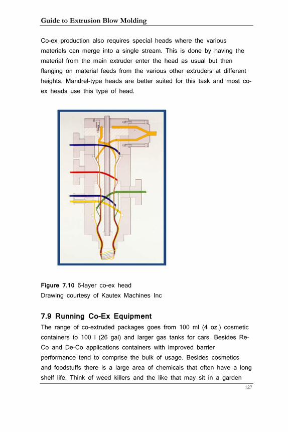
Guide to Extrusion Blow Molding
127
Co-ex production also requires special heads where the various materials can merge into a single stream. This is done by having the material from the main extruder enter the head as usual but then flanging on material feeds from the various other extruders at different heights. Mandrel-type heads are better suited for this task and most co-ex heads use this type of head.
Figure 7.10 6-layer co-ex head Drawing courtesy of Kautex Machines Inc
7.9 Running Co-Ex Equipment The range of co-extruded packages goes from 100 ml (4 oz.) cosmetic containers to 100 l (26 gal) and larger gas tanks for cars. Besides Re-Co and De-Co applications containers with improved barrier performance tend to comprise the bulk of usage. Besides cosmetics and foodstuffs there is a large area of chemicals that often have a long shelf life. Think of weed killers and the like that may sit in a garden
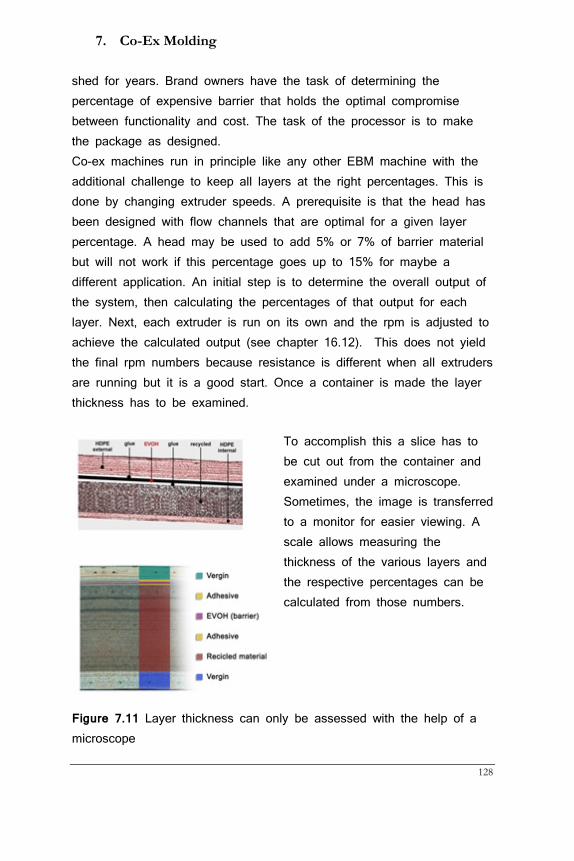
7. Co-Ex Molding
128
shed for years. Brand owners have the task of determining the percentage of expensive barrier that holds the optimal compromise between functionality and cost. The task of the processor is to make the package as designed. Co-ex machines run in principle like any other EBM machine with the additional challenge to keep all layers at the right percentages. This is done by changing extruder speeds. A prerequisite is that the head has been designed with flow channels that are optimal for a given layer percentage. A head may be used to add 5% or 7% of barrier material but will not work if this percentage goes up to 15% for maybe a different application. An initial step is to determine the overall output of the system, then calculating the percentages of that output for each layer. Next, each extruder is run on its own and the rpm is adjusted to achieve the calculated output (see chapter 16.12). This does not yield the final rpm numbers because resistance is different when all extruders are running but it is a good start. Once a container is made the layer thickness has to be examined.
To accomplish this a slice has to be cut out from the container and examined under a microscope. Sometimes, the image is transferred to a monitor for easier viewing. A scale allows measuring the thickness of the various layers and the respective percentages can be calculated from those numbers.
Figure 7.11 Layer thickness can only be assessed with the help of a microscope
Guide to Extrusion Blow Molding
129
8. Basic Hydraulics, Pneumatics, and Machine Control
While this book is not about maintenance and repair of machines I have found it important for operators and technicians to be somewhat familiar with the way their machines actually operate.
8.1 Hydraulics
The hydraulic system consists of
• Electric motor
• Hydraulic pump
• Hydraulic tank or reservoir
• Heat exchanger
• Pipes, hoses, filters etc.
• Valves
o Directional valves
o Proportional valves
o Servo valves
o Flow controls
o Pressure reducers
• Cylinders
It converts electric power into liquid pressure. Various valves open and close at predetermined times to drive cylinders that do the actual work. During pressurization and cylinder movement friction forces create heat that increases oil temperature. A heat exchanger moves water from a water tower through a space where oil flows through from the cylinders to the hydraulic tank.
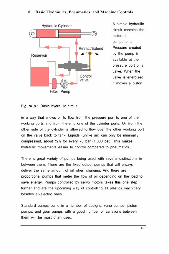
8. Basic Hydraulics, Pneumatics, and Machine Controls
130
A simple hydraulic circuit contains the pictured components. Pressure created by the pump is available at the pressure port of a valve. When the valve is energized it moves a piston
Figure 8.1 Basic hydraulic circuit
in a way that allows oil to flow from the pressure port to one of the working ports and from there to one of the cylinder ports. Oil from the other side of the cylinder is allowed to flow over the other working port on the valve back to tank. Liquids (unlike air) can only be minimally compressed, about ½% for every 70 bar (1,000 psi). This makes hydraulic movements easier to control compared to pneumatics.
There is great variety of pumps being used with several distinctions in between them. There are the fixed output pumps that will always deliver the same amount of oil when charging. And there are proportional pumps that meter the flow of oil depending on the load to save energy. Pumps controlled by servo motors takes this one step further and are the upcoming way of controlling all plastics machinery besides all-electric ones.
Standard pumps come in a number of designs: vane pumps, piston pumps, and gear pumps with a good number of variations between them will be most often used.
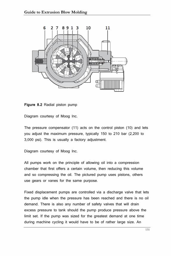
Guide to Extrusion Blow Molding
131
Figure 8.2 Radial piston pump
Diagram courtesy of Moog Inc.
The pressure compensator (11) acts on the control piston (10) and lets you adjust the maximum pressure, typically 150 to 210 bar (2,200 to 3,000 psi). This is usually a factory adjustment.
Diagram courtesy of Moog Inc.
All pumps work on the principle of allowing oil into a compression chamber that first offers a certain volume, then reducing this volume and so compressing the oil. The pictured pump uses pistons, others use gears or vanes for the same purpose.
Fixed displacement pumps are controlled via a discharge valve that lets the pump idle when the pressure has been reached and there is no oil demand. There is also any number of safety valves that will drain excess pressure to tank should the pump produce pressure above the limit set. If the pump was sized for the greatest demand at one time during machine cycling it would have to be of rather large size. An
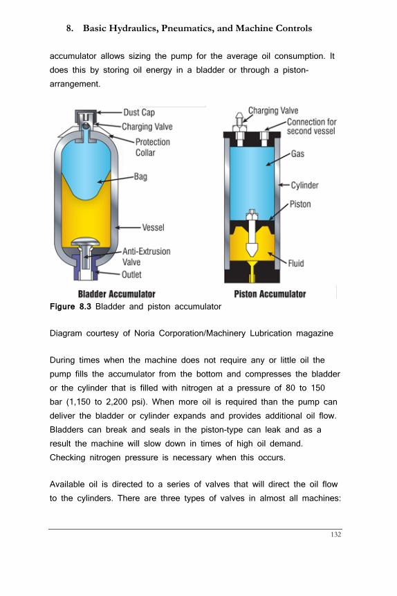
8. Basic Hydraulics, Pneumatics, and Machine Controls
132
accumulator allows sizing the pump for the average oil consumption. It does this by storing oil energy in a bladder or through a piston-arrangement.
Figure 8.3 Bladder and piston accumulator
Diagram courtesy of Noria Corporation/Machinery Lubrication magazine
During times when the machine does not require any or little oil the pump fills the accumulator from the bottom and compresses the bladder or the cylinder that is filled with nitrogen at a pressure of 80 to 150 bar (1,150 to 2,200 psi). When more oil is required than the pump can deliver the bladder or cylinder expands and provides additional oil flow. Bladders can break and seals in the piston-type can leak and as a result the machine will slow down in times of high oil demand. Checking nitrogen pressure is necessary when this occurs.
Available oil is directed to a series of valves that will direct the oil flow to the cylinders. There are three types of valves in almost all machines:
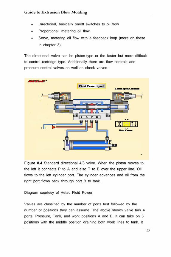
Guide to Extrusion Blow Molding
133
• Directional, basically on/off switches to oil flow
• Proportional, metering oil flow
• Servo, metering oil flow with a feedback loop (more on these
in chapter 3)
The directional valve can be piston-type or the faster but more difficult to control cartridge type. Additionally there are flow controls and pressure control valves as well as check valves.
Figure 8.4 Standard directional 4/3 valve. When the piston moves to the left it connects P to A and also T to B over the upper line. Oil flows to the left cylinder port. The cylinder advances and oil from the right port flows back through port B to tank.
Diagram courtesy of Hetac Fluid Power
Valves are classified by the number of ports first followed by the number of positions they can assume. The above shown valve has 4 ports: Pressure, Tank, and work positions A and B. It can take on 3 positions with the middle position draining both work lines to tank. It
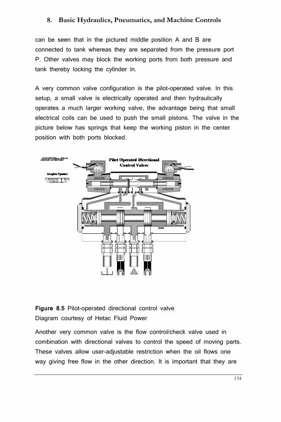
8. Basic Hydraulics, Pneumatics, and Machine Controls
134
can be seen that in the pictured middle position A and B are connected to tank whereas they are separated from the pressure port P. Other valves may block the working ports from both pressure and tank thereby locking the cylinder in.
A very common valve configuration is the pilot-operated valve. In this setup, a small valve is electrically operated and then hydraulically operates a much larger working valve, the advantage being that small electrical coils can be used to push the small pistons. The valve in the picture below has springs that keep the working piston in the center position with both ports blocked.
Figure 8.5 Pilot-operated directional control valve Diagram courtesy of Hetac Fluid Power
Another very common valve is the flow control/check valve used in combination with directional valves to control the speed of moving parts. These valves allow user-adjustable restriction when the oil flows one way giving free flow in the other direction. It is important that they are
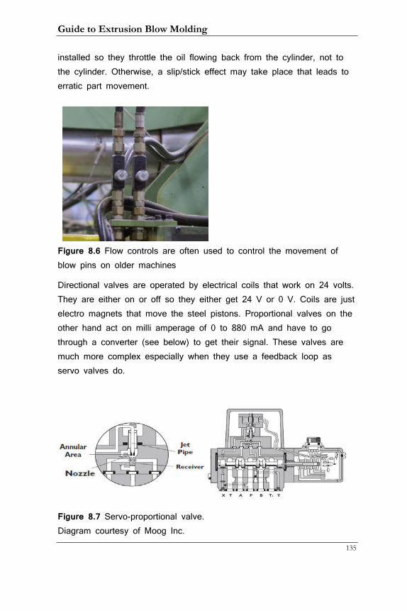
Guide to Extrusion Blow Molding
135
installed so they throttle the oil flowing back from the cylinder, not to the cylinder. Otherwise, a slip/stick effect may take place that leads to erratic part movement.
Figure 8.6 Flow controls are often used to control the movement of blow pins on older machines
Directional valves are operated by electrical coils that work on 24 volts. They are either on or off so they either get 24 V or 0 V. Coils are just electro magnets that move the steel pistons. Proportional valves on the other hand act on milli amperage of 0 to 880 mA and have to go through a converter (see below) to get their signal. These valves are much more complex especially when they use a feedback loop as servo valves do.
Figure 8.7 Servo-proportional valve. Diagram courtesy of Moog Inc.
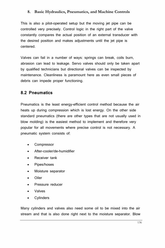
8. Basic Hydraulics, Pneumatics, and Machine Controls
136
This is also a pilot-operated setup but the moving jet pipe can be controlled very precisely. Control logic in the right part of the valve constantly compares the actual position of an external transducer with the desired position and makes adjustments until the jet pipe is centered.
Valves can fail in a number of ways: springs can break, coils burn, abrasion can lead to leakage. Servo valves should only be taken apart by qualified technicians but directional valves can be inspected by maintenance. Cleanliness is paramount here as even small pieces of debris can impede proper functioning.
8.2 Pneumatics
Pneumatics is the least energy-efficient control method because the air heats up during compression which is lost energy. On the other side standard pneumatics (there are other types that are not usually used in blow molding) is the easiest method to implement and therefore very popular for all movements where precise control is not necessary. A pneumatic system consists of:
• Compressor
• After-cooler/de-humidifier
• Receiver tank
• Pipes/hoses
• Moisture separator
• Oiler
• Pressure reducer
• Valves
• Cylinders
Many cylinders and valves also need some oil to be mixed into the air stream and that is also done right next to the moisture separator. Blow
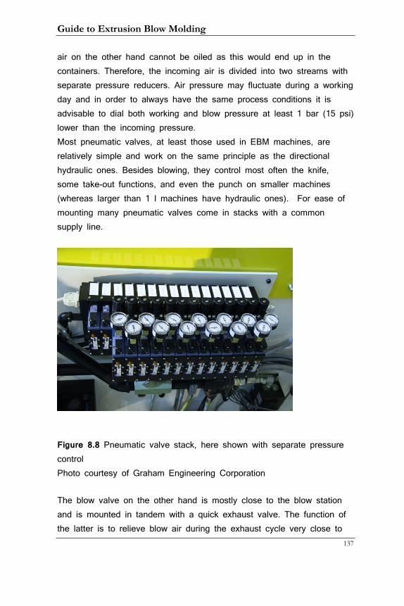
Guide to Extrusion Blow Molding
137
air on the other hand cannot be oiled as this would end up in the containers. Therefore, the incoming air is divided into two streams with separate pressure reducers. Air pressure may fluctuate during a working day and in order to always have the same process conditions it is advisable to dial both working and blow pressure at least 1 bar (15 psi) lower than the incoming pressure. Most pneumatic valves, at least those used in EBM machines, are relatively simple and work on the same principle as the directional hydraulic ones. Besides blowing, they control most often the knife, some take-out functions, and even the punch on smaller machines (whereas larger than 1 l machines have hydraulic ones). For ease of mounting many pneumatic valves come in stacks with a common supply line.
Figure 8.8 Pneumatic valve stack, here shown with separate pressure control Photo courtesy of Graham Engineering Corporation
The blow valve on the other hand is mostly close to the blow station and is mounted in tandem with a quick exhaust valve. The function of the latter is to relieve blow air during the exhaust cycle very close to
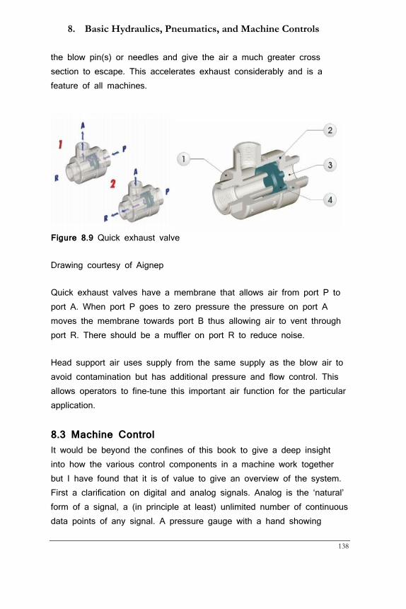
8. Basic Hydraulics, Pneumatics, and Machine Controls
138
the blow pin(s) or needles and give the air a much greater cross section to escape. This accelerates exhaust considerably and is a feature of all machines.
Figure 8.9 Quick exhaust valve
Drawing courtesy of Aignep
Quick exhaust valves have a membrane that allows air from port P to port A. When port P goes to zero pressure the pressure on port A moves the membrane towards port B thus allowing air to vent through port R. There should be a muffler on port R to reduce noise.
Head support air uses supply from the same supply as the blow air to avoid contamination but has additional pressure and flow control. This allows operators to fine-tune this important air function for the particular application.
8.3 Machine Control It would be beyond the confines of this book to give a deep insight into how the various control components in a machine work together but I have found that it is of value to give an overview of the system. First a clarification on digital and analog signals. Analog is the ‘natural’ form of a signal, a (in principle at least) unlimited number of continuous data points of any signal. A pressure gauge with a hand showing
Guide to Extrusion Blow Molding
139
pressure in bar or psi is an example: while one may not be able to recognize more than a few dozen or hundred positions of the hand it can take on any position on the dial. A digital signal by contrast is limited to discrete steps, which is referred to as bandwidth. These steps are always to the power of 2 and 212 equaling 4,096 is often used in modern controllers. That means that a pressure reading from 0 to 150 bar (2,175 psi) can only be read in steps of 0.037 bar or 0.53 psi. Lucky for us, this is more accurate than we need for the purpose of controlling the machine functions. Properly calibrated, digital systems actually allow more precise adjustments because the values can be specified with higher accuracy. Here are the major parts of the control system
• Programmable Logic Controller (PLC)
o CPU card, the heart of the PLC
o Input cards
o Output cards
o Temperature control cards
o Conversion cards
• Linear and pressure transducers
• Digital and analog switches
• Operator Interface (OI) also called Graphical User Interface
(GUI)
Unlike a home or business PC the PLC runs a sequential program continuously. With the OI the operator sets values for timers, temperatures and the like and the PLC checks the various switches and transducers and takes action when the program tells it to. Communication with the PLC is rather difficult; it only understands binary numbers, that is ones and zeroes. Therefore, every input has to be translated into this form. Operator input is actually quite easy and runs in the background in the same way as on a PC. Whenever you enter the number 8 on the screen this is converted to ‘1000’ and sent to the PLC.
8. Basic Hydraulics, Pneumatics, and Machine Controls
140
A position switch transmits a ‘1’ when it is on and a ‘0’ when it is off into a digital input card. Transducers always emit analog signals. Typical values are 0 to 10 V or 4 to 20 mA. These have to be converted into digital ones and zeroes via an analog to digital (A/D) conversion card. When the PLC sends a signal to a directional valve it sends a ‘1’ to turn it on and a ‘0’ to turn it off to a digital output card where the signal is amplified and sent to the valve. However, when a proportional valve is addressed the PLC code goes through a digital to analog (D/A) conversion card where the binary number is translated into the correct signal. Sometimes, valves have additional cards that take a 0 to 5 V or 0 to 10 V input signal and convert it to 0 to 880 mA.
Figure 8.10 Temperature Control Circuit
This diagram shows a number of components needed to turn on a heater band. The steps are as follows:
• The thermocouple reads the temperature in milli Volts
• The mV signal is converted to a binary number in the A/D
card
• The binary number is sent to the PLC
• The PLC checks and is instructed to turn the heater band on
Thermocouple
220 VHeaterband
Connectors24 V
5 V / 16 bit 2 A
24 V200 mA
Breakout BoardD/A A/D conversion
Relay
PLC
Amplif ier Board
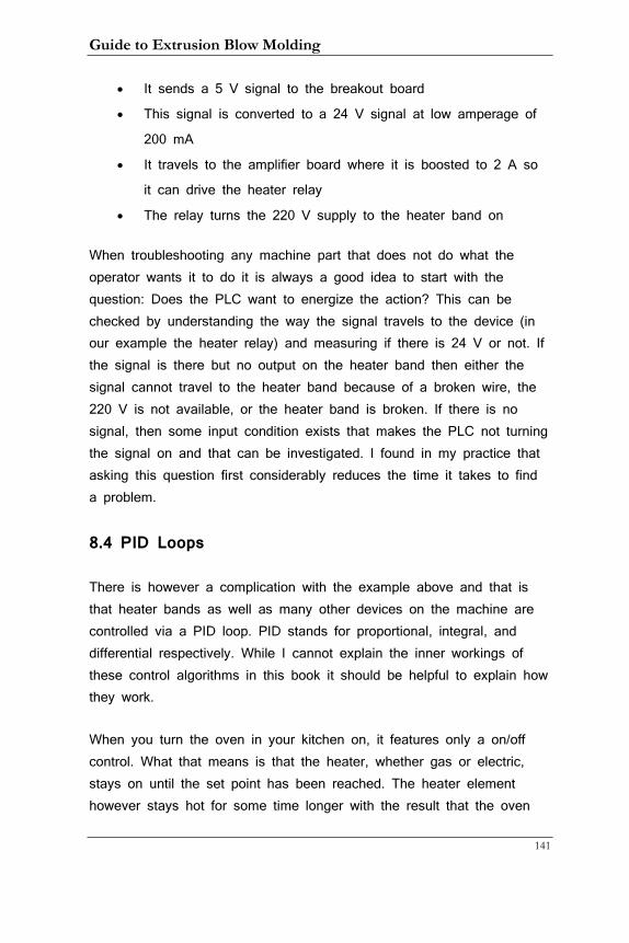
Guide to Extrusion Blow Molding
141
• It sends a 5 V signal to the breakout board
• This signal is converted to a 24 V signal at low amperage of
200 mA
• It travels to the amplifier board where it is boosted to 2 A so
it can drive the heater relay
• The relay turns the 220 V supply to the heater band on
When troubleshooting any machine part that does not do what the operator wants it to do it is always a good idea to start with the question: Does the PLC want to energize the action? This can be checked by understanding the way the signal travels to the device (in our example the heater relay) and measuring if there is 24 V or not. If the signal is there but no output on the heater band then either the signal cannot travel to the heater band because of a broken wire, the 220 V is not available, or the heater band is broken. If there is no signal, then some input condition exists that makes the PLC not turning the signal on and that can be investigated. I found in my practice that asking this question first considerably reduces the time it takes to find a problem.
8.4 PID Loops
There is however a complication with the example above and that is that heater bands as well as many other devices on the machine are controlled via a PID loop. PID stands for proportional, integral, and differential respectively. While I cannot explain the inner workings of these control algorithms in this book it should be helpful to explain how they work.
When you turn the oven in your kitchen on, it features only a on/off control. What that means is that the heater, whether gas or electric, stays on until the set point has been reached. The heater element however stays hot for some time longer with the result that the oven
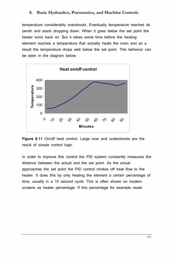
8. Basic Hydraulics, Pneumatics, and Machine Controls
142
temperature considerably overshoots. Eventually temperature reaches its zenith and starts dropping down. When it goes below the set point the heater turns back on. But it takes some time before the heating element reaches a temperature that actually heats the oven and as a result the temperature drops well below the set point. This behavior can be seen in the diagram below.
Figure 8.11 On/off heat control. Large over and undershoots are the result of simple control logic
In order to improve this control the PID system constantly measures the distance between the actual and the set point. As the actual approaches the set point the PID control chokes off heat flow to the heater. It does this by only heating the element a certain percentage of time, usually in a 10 second cycle. This is often shown on modern screens as heater percentage. If this percentage for example reads
Heat on/off control
0
100
200
300
400
0 10 20 30 40 50 60 70 80 90
Minutes
Tem
pera
ture
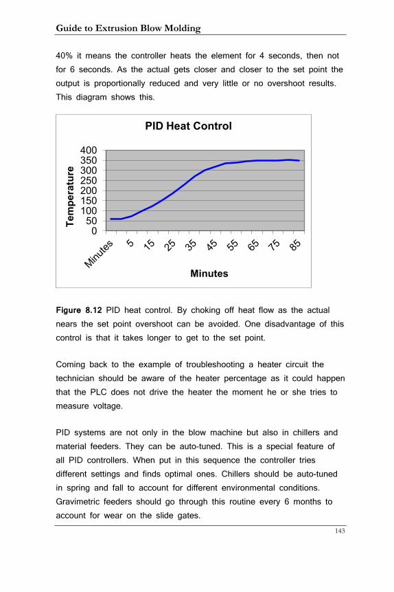
Guide to Extrusion Blow Molding
143
40% it means the controller heats the element for 4 seconds, then not for 6 seconds. As the actual gets closer and closer to the set point the output is proportionally reduced and very little or no overshoot results. This diagram shows this.
Figure 8.12 PID heat control. By choking off heat flow as the actual nears the set point overshoot can be avoided. One disadvantage of this control is that it takes longer to get to the set point.
Coming back to the example of troubleshooting a heater circuit the technician should be aware of the heater percentage as it could happen that the PLC does not drive the heater the moment he or she tries to measure voltage.
PID systems are not only in the blow machine but also in chillers and material feeders. They can be auto-tuned. This is a special feature of all PID controllers. When put in this sequence the controller tries different settings and finds optimal ones. Chillers should be auto-tuned in spring and fall to account for different environmental conditions. Gravimetric feeders should go through this routine every 6 months to account for wear on the slide gates.
0 50
100 150 200 250 300 350 400
Tem
pera
ture
Minutes
PID Heat Control
8. Basic Hydraulics, Pneumatics, and Machine Controls
144
8.5 Statistical Process Control (SPC)
SPC has a number of components. Their purpose is to track changes in machine and environmental parameters as well as in container characteristics. I’ll describe the latter part briefly as this is now part of most companies’ quality control procedure. Monitoring parameters for out-of-spec instances is no longer enough; the values for dimensions and other measurable characteristics of containers must now be processed to determine if the bottles are produced in a stable process. This greatly reduces the chances of out-of-spec containers. Fillers hate line problems caused by inferior bottles and are driving converters to ever closer process capability. One such statistical factor is the process capability factor cpk. To understand how it is computed and what process yields the highest (best) cpk factor, I’ll explain a few key components.
• X-value: moving average of a number of samples
• Range: difference between the lowest and highest x-value
• Standard deviation (SD): deviation from the mean or average.
All spreadsheet programs can calculate this so there is no
need to know how to do it. The larger the SD the more the
samples vary
• Specification limits: the highest and lowest value of a
specification, e.g. a bottle with the weight specification 35 g +/-
2 would have 37 as upper and 33 as lower specification limit
(USL and LSL respectively)
• Control limits: mean (x-value) +/- 3 times SD. When all values
fall within the control limits 99.7% of all samples conform to the
specification
• Cpk-value: the smaller of two numbers: (upper specification limit
– mean) / 3 * SD or (mean – lower specification limit)/ 3 * SD
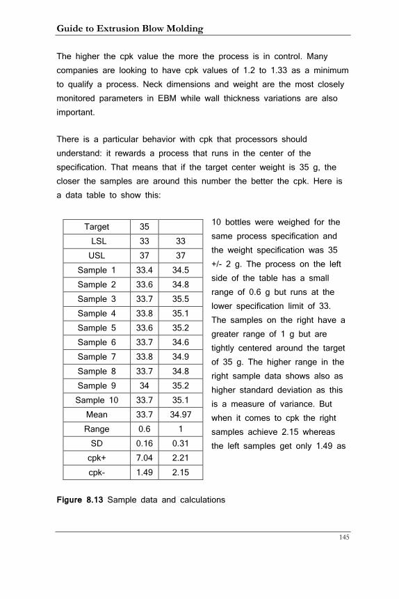
Guide to Extrusion Blow Molding
145
The higher the cpk value the more the process is in control. Many companies are looking to have cpk values of 1.2 to 1.33 as a minimum to qualify a process. Neck dimensions and weight are the most closely monitored parameters in EBM while wall thickness variations are also important.
There is a particular behavior with cpk that processors should understand: it rewards a process that runs in the center of the specification. That means that if the target center weight is 35 g, the closer the samples are around this number the better the cpk. Here is a data table to show this:
10 bottles were weighed for the same process specification and the weight specification was 35 +/- 2 g. The process on the left side of the table has a small range of 0.6 g but runs at the lower specification limit of 33. The samples on the right have a greater range of 1 g but are tightly centered around the target of 35 g. The higher range in the right sample data shows also as higher standard deviation as this is a measure of variance. But when it comes to cpk the right samples achieve 2.15 whereas the left samples get only 1.49 as
Figure 8.13 Sample data and calculations
Target 35 LSL 33 33 USL 37 37
Sample 1 33.4 34.5 Sample 2 33.6 34.8 Sample 3 33.7 35.5 Sample 4 33.8 35.1 Sample 5 33.6 35.2 Sample 6 33.7 34.6 Sample 7 33.8 34.9 Sample 8 33.7 34.8 Sample 9 34 35.2 Sample 10 33.7 35.1
Mean 33.7 34.97 Range 0.6 1 SD 0.16 0.31 cpk+ 7.04 2.21 cpk- 1.49 2.15
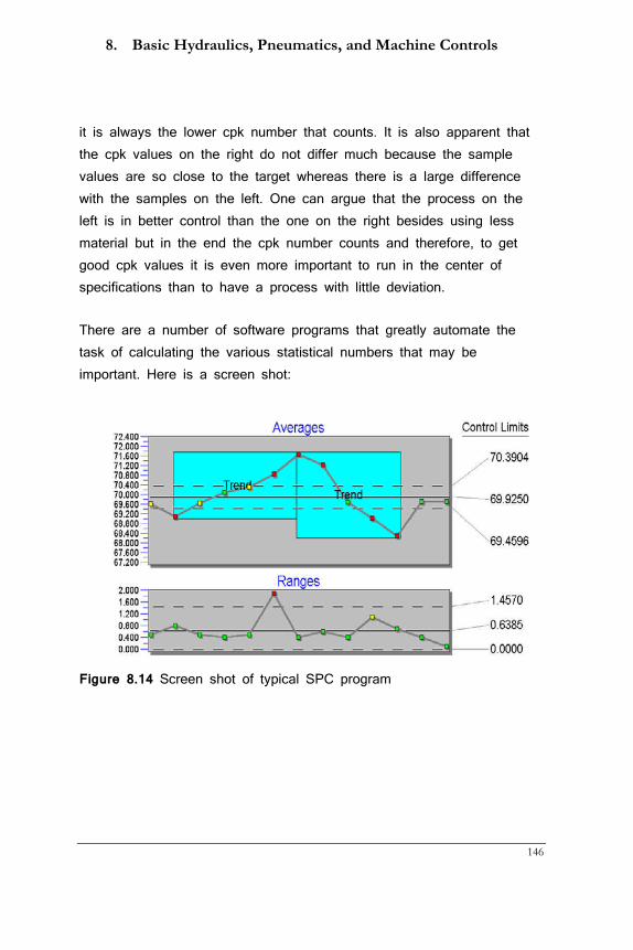
8. Basic Hydraulics, Pneumatics, and Machine Controls
146
it is always the lower cpk number that counts. It is also apparent that the cpk values on the right do not differ much because the sample values are so close to the target whereas there is a large difference with the samples on the left. One can argue that the process on the left is in better control than the one on the right besides using less material but in the end the cpk number counts and therefore, to get good cpk values it is even more important to run in the center of specifications than to have a process with little deviation.
There are a number of software programs that greatly automate the task of calculating the various statistical numbers that may be important. Here is a screen shot:
Figure 8.14 Screen shot of typical SPC program
Guide to Extrusion Blow Molding
147
9 Setting Up an EBM machine
Plant managers and others routinely complain about how long change-overs take. If personnel are lazy or un-skilled, they have a point. But in many cases it is issues with scheduling, poor maintenance, and a lack of training and supervision that is to blame for unreasonably long change-over times. This section cannot cover in detail all the steps that are involved in setting up a machine. For that the machine types and the various versions of manufacturers are too different from each other. Instead, I will concentrate on the more general issues but before we go into that let’s first review the different kinds of change-overs that are part of blow molding life.
9.1 Change-over differences
The least labour-intensive but often the most time-consuming change is color. As discussed in chapter 2.12 a big disadvantage of mandrel heads is their long color change time. This can take from 2 to 8 hours and the use of purge agents does not seem to cut down on this interval. Torpedo and spiral heads are considerably better and can be counted on to do a standard change anywhere from 10 to 30 minutes. From an organisational point of view it is paramount that people in charge of scheduling are aware that a change from white to dark blue is relatively easy where the reverse can easily take double the time. Therefore, if at all possible, colors should be changed from light to dark to darkest and then back to light. Only the last change will then be a long one. Running a process at the low end of the temperature range and so keeping material degradation down also helps. The next, least labour-intensive is when molds are changed without a change in neck dimensions. In this case the original blow pins can be used again but cutting sleeves should be changed before the new run starts. Next comes a change in both mold and blow pins. Blow pin adjustments take time to get it right but can be done while the extruder is purging whereas mold changes can only be done simultaneously
9. Setting up an EBM Machine
148
when the molds are mounted from the top on shuttle machines. Head tooling change would be next on the list as the removal and cleaning of the old and the mounting and adjustment of the new tooling takes considerable time. An even more time-consuming change-over is when the cavitation is different. For this the head must be replaced and the blow pin positions changed and pins added or subtracted. Having the heater band cables and receptacles properly labeled is helpful though and should always be done. An even longer change-over takes places when on top of a head the screw also needs to be changed because the new material requires it. Once the head is off it does not take that much time to change the screw but it is extra work. Looking at these different cases it becomes obvious that only careful analysis of what was actually done can reveal if a change-over took longer than what can be expected. It is however equally important to monitor the machine performance after a change-over as to productivity and number of necessary interventions. It would be counterproductive to reward personnel that excel in reducing change-over time by skipping steps and leaving the machine less than well adjusted for a successful production run.
9.2 Preparation
I cannot stress enough how important it is to prepare all parts needed for a change-over while the machine is still running. Far too often setup people have to interrupt what they are doing because something is missing. Here is a (by no means comprehensive) list of possible items needed:
• Molds • Take-out and deflash/punch tooling • Head tooling • Blow pins or new cutting sleeves, striker plates • Special tools you may need • Brass and copper cleaning tools
Guide to Extrusion Blow Molding
149
• New head • Blow pin holders • New color masterbatch • Knife and pre-pinch devices • Head cleaning tools including a propane burner • Screw • Thermolators • Gloves, safety glasses etc. • Setup sheet or electronic machine setup data for the
new job
9.3 Setup sheets Setup sheets should contain all pertinent information. Besides the obvious information that can be gathered from the screen or comes up automatically when a recipe is loaded it should also contain a date (as there are seasonal differences) and info on material composition and air pressure and water temperature. The info on these sheets, while a good starting point, has to be taken with a critical eye. In a multi-shift environment the author of the sheet is most often unknown and may not have been as knowledgeable as one could wish. Maybe the process was not running that well with the parameters of the sheet or the water temperature was different. The latter point is especially important when operators choke the water flow during the summer months. There should be a note to that effect to alert operators on subsequent runs. All too often data on the sheet is taken too literally and machines are running less than optimal as a consequence. 9.4 Removing old tooling On machines where a purging parison is not in the way all tooling (except dies and pins of course) should be removed while the extruder is purged or emptied. If that is not possible I suggest taking the tool(s) out after disconnecting all water and (if applicable) hydraulic lines, then purge. During that time all water should be blown out of the mold and the surface sprayed with a protective coating. Now is also a good time to check if the leader pins and bushings are in a good state of repair. All surfaces should also be cleaned and vent holes (if there are any)
9. Setting up an EBM Machine
150
blown out. If there is damage it should be repaired now and not when the mold is to be used again. Dies and pins should be thoroughly cleaned with the appropriate tools. Removing as much material as possible while the die is still mounted to the head speeds up this process. Ideally, no propane is needed. When removing the die heater band make absolutely sure that the heater band is turned off. If it is using 480 V I suggest to physically disconnecting it to reduce the risk of electric shock that can result in serious injury and even death. The mold(s) should then be stored on a wooden surface in the closed position. They should be clearly marked and all parts that are specific to this mold only should be stored in the same location to make them easier to find.
9.5 Purging the extruder and head Typically, it is color that needs to change and only sometimes the material. Color change-over time depends on a number of factors:
• Type of head
• New and existing color
• State of maintenance for screw and head
Spiral heads are generally best when it comes to color changes with spider heads close behind. Mandrel heads however typically take hours whereas the other heads the time can be measured in minutes. This is because the areas in mandrel heads where the material streams meet tend to lead to color remnants that take a long time to be flushed out. The use of purge compounds is often not effective and forces a significant amount of material to go to waste. Some companies let all purge materials go to waste though while others run bottles that are immediately re-ground and this regrind is then mixed with other regrind and added to the center layer of a multi-layer system or to a very dark color mix Another way of approaching this issue especially with mandrel heads is to disassemble and clean the head. Once taken apart the extruder can now be cleaned much more efficiently. Letting the screw ‘bite off’ from a flattened parison for example works very well and fast. An even more
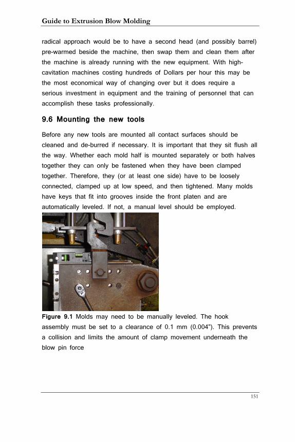
Guide to Extrusion Blow Molding
151
radical approach would be to have a second head (and possibly barrel) pre-warmed beside the machine, then swap them and clean them after the machine is already running with the new equipment. With high-cavitation machines costing hundreds of Dollars per hour this may be the most economical way of changing over but it does require a serious investment in equipment and the training of personnel that can accomplish these tasks professionally.
9.6 Mounting the new tools
Before any new tools are mounted all contact surfaces should be cleaned and de-burred if necessary. It is important that they sit flush all the way. Whether each mold half is mounted separately or both halves together they can only be fastened when they have been clamped together. Therefore, they (or at least one side) have to be loosely connected, clamped up at low speed, and then tightened. Many molds have keys that fit into grooves inside the front platen and are automatically leveled. If not, a manual level should be employed.
Figure 9.1 Molds may need to be manually leveled. The hook assembly must be set to a clearance of 0.1 mm (0.004”). This prevents a collision and limits the amount of clamp movement underneath the blow pin force
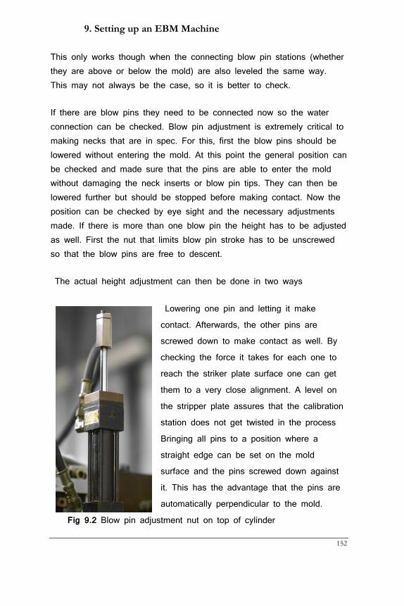
9. Setting up an EBM Machine
152
This only works though when the connecting blow pin stations (whether they are above or below the mold) are also leveled the same way. This may not always be the case, so it is better to check.
If there are blow pins they need to be connected now so the water connection can be checked. Blow pin adjustment is extremely critical to making necks that are in spec. For this, first the blow pins should be lowered without entering the mold. At this point the general position can be checked and made sure that the pins are able to enter the mold without damaging the neck inserts or blow pin tips. They can then be lowered further but should be stopped before making contact. Now the position can be checked by eye sight and the necessary adjustments made. If there is more than one blow pin the height has to be adjusted as well. First the nut that limits blow pin stroke has to be unscrewed so that the blow pins are free to descent.
The actual height adjustment can then be done in two ways
Lowering one pin and letting it make
contact. Afterwards, the other pins are
screwed down to make contact as well. By
checking the force it takes for each one to
reach the striker plate surface one can get
them to a very close alignment. A level on
the stripper plate assures that the calibration
station does not get twisted in the process
Bringing all pins to a position where a
straight edge can be set on the mold
surface and the pins screwed down against
it. This has the advantage that the pins are
automatically perpendicular to the mold.
Fig 9.2 Blow pin adjustment nut on top of cylinder
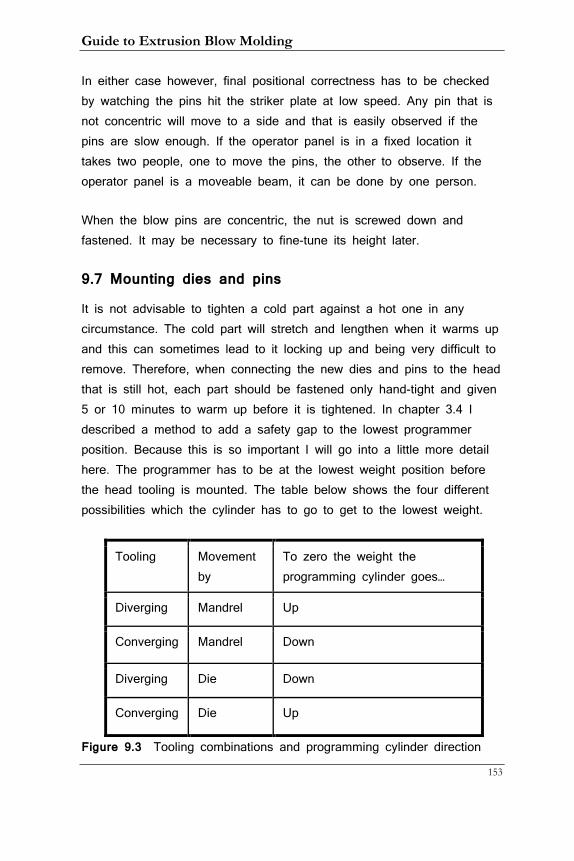
Guide to Extrusion Blow Molding
153
In either case however, final positional correctness has to be checked by watching the pins hit the striker plate at low speed. Any pin that is not concentric will move to a side and that is easily observed if the pins are slow enough. If the operator panel is in a fixed location it takes two people, one to move the pins, the other to observe. If the operator panel is a moveable beam, it can be done by one person.
When the blow pins are concentric, the nut is screwed down and fastened. It may be necessary to fine-tune its height later.
9.7 Mounting dies and pins
It is not advisable to tighten a cold part against a hot one in any circumstance. The cold part will stretch and lengthen when it warms up and this can sometimes lead to it locking up and being very difficult to remove. Therefore, when connecting the new dies and pins to the head that is still hot, each part should be fastened only hand-tight and given 5 or 10 minutes to warm up before it is tightened. In chapter 3.4 I described a method to add a safety gap to the lowest programmer position. Because this is so important I will go into a little more detail here. The programmer has to be at the lowest weight position before the head tooling is mounted. The table below shows the four different possibilities which the cylinder has to go to get to the lowest weight.
Tooling Movement by
To zero the weight the programming cylinder goes…
Diverging Mandrel Up
Converging Mandrel Down
Diverging Die Down
Converging Die Up
Figure 9.3 Tooling combinations and programming cylinder direction
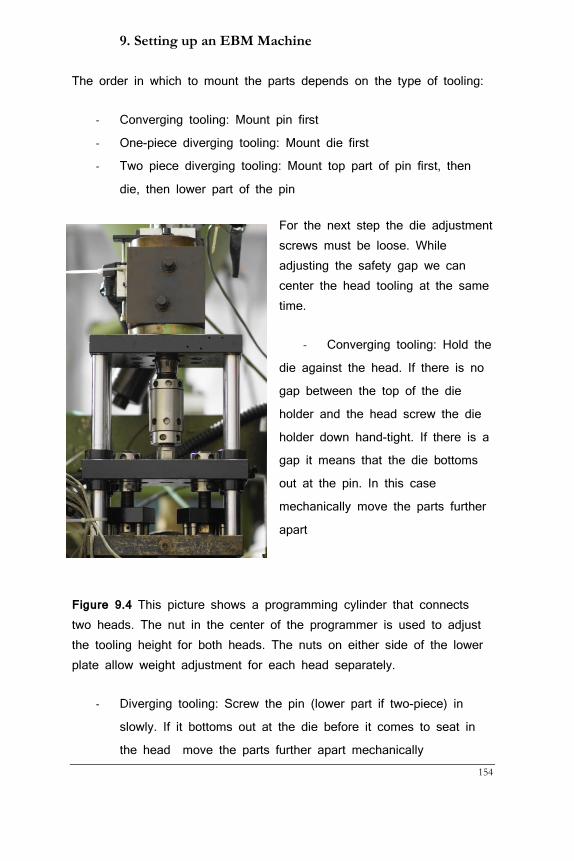
9. Setting up an EBM Machine
154
The order in which to mount the parts depends on the type of tooling:
- Converging tooling: Mount pin first
- One-piece diverging tooling: Mount die first
- Two piece diverging tooling: Mount top part of pin first, then
die, then lower part of the pin
For the next step the die adjustment screws must be loose. While adjusting the safety gap we can center the head tooling at the same time.
- Converging tooling: Hold the
die against the head. If there is no
gap between the top of the die
holder and the head screw the die
holder down hand-tight. If there is a
gap it means that the die bottoms
out at the pin. In this case
mechanically move the parts further
apart
Figure 9.4 This picture shows a programming cylinder that connects two heads. The nut in the center of the programmer is used to adjust the tooling height for both heads. The nuts on either side of the lower plate allow weight adjustment for each head separately.
- Diverging tooling: Screw the pin (lower part if two-piece) in
slowly. If it bottoms out at the die before it comes to seat in
the head move the parts further apart mechanically
Guide to Extrusion Blow Molding
155
- Now mechanically let the parts bottom out on each other
without putting any torque on them. They are now centered
and the dies can be fastened in this position. You can also
tighten the adjustment screws to some degree. Now adjust the
safety gap to 0.1 to 0.2 mm (0.004” to 0.008”) mechanically.
This will prevent damage to the tooling and a choked head.
When hydraulic cylinders are connected to moving mold inserts it is crucial that they are connected in the right way. Clearly marked hoses help. Hydraulic movements are typically controlled with flow controls and it is a good idea to adjust these before going in production. Movements should most often be on the slow side to give the material time to move. Greasing all leader pins and guide bars at this point is never wrong!
9.8 Starting up the machine
Heats, timers, and the programmer profile should be reviewed before starting the machine up and a previous setup that may have been loaded from an existing recipe should be viewed critically. If there is no recipe from a previous run the range or profile setting can be set to 20% to 30%. This parameter determines how much the tool will move when the program covers the entire screen and in most cases only a few millimeters of stroke are required. The weight adjustment will determine the weight of the container and needs to be estimated at startup. Once a few containers are made it can then be fine-tuned and the extruder rpm and/or shotsize (for discontinuous machines) dialed in. Extruder rpm follows different guidelines depending on the type of machine used:
• On recip machines the rpm should be such that the
extruder stops 1 to 2 seconds before material push-out.
9. Setting up an EBM Machine
156
It can be raised when more shear is needed to melt
the material
• On shuttle and wheel machines the rpm determines the
length of the bottom flash or ‘tails’
• On accumulator head machines the extruder may run
continuous or dis-continuous. In the latter case the
same rules apply as for the recip machine. If it is
continuous the rpm needs to be fast enough to always
fill the accumulator to shotsize in time.
It is practical to start with a straight profile and change it after container wall thickness has been evaluated. This is not always possible as sometimes the profile has to be changed to get a good cut or a particular bottle feature needs more or less material right away. It is important however to approach the programming with an open mind and improve on container properties whenever possible even when a recipe from a previous run can be downloaded.
Weights for multiple parisons have to be adjusted mechanically (unless each parison has its own programming cylinder). Since we do not want to lose the safety gap weight can only be added. Therefore, even if 3 cavities are too light and one too heavy, you have to increase the weight on the three cavities rather than reducing it for the fourth. Differences in tail length should be controlled via the chokes that are on the distributor rather than by temperature (except for PVC where chokes are not possible). Plastics are unpredictable enough; we want to keep everything else the same for a stable process. Getting tail length and weight between multiple cavities just right will require a few adjustments as these two parameters affect each other. With all heads set to the same safety gap and the same temperatures it becomes easier to succeed.
Guide to Extrusion Blow Molding
157
9.9 Quality checks
Before submitting any samples to QC operators should check critical dimensions on their own to save time. Keep in mind though that measuring bottles that just exit the machine must take into account that they will shrink over the next 24 hours. Most of that shrinkage happens in the next 2 hours but even that is too long to wait as the change-over is only finished when the machine makes again acceptable bottles. You can assume that bottles will shrink just under 1% from the hot to the cold state (this of course depends on how high the de-molding temperature is). That means a 28 mm neck will measure .28 mm (0.011”) larger right out of the machine. ‘S’ and ‘H’ dimensions can be adjusted by lowering or raising the blow pin nut. If these numbers are close to the upper tolerance limit the neck will be just right when the bottle is cold. Fill and overflow volume can be adjusted by the same shrinkage mechanism: to get larger volume cool the container longer; it will then shrink less. This is not optimal as cycle time should follow its own guidelines but it can help as a temporary measure before changes to the mold (for example on the push-up) can be implemented.
While it is possible to speed the machine up by reducing the clamping or carriages speed, this is often not worth the effort as the gains will be small. Only when one side of a double-sided machine is noticeably slower than the other should time be expended to speed up the slower side. The two items operators should pay most attention to are the blow and exhaust time. Blow time depends mostly on the time it takes to cool the thickest wall in the container to a temperature at which the part can be de-molded without excessive shrinkage or weak spots. Circulating the blow air or using cold blow air down to -35°C (-31°F) will reduce the necessary cooling time greatly but whether these systems are used or not it is up to the operator to decide at what temperature the part can be de-molded. I encourage experimenting with different blow times. This can be done by making samples at lower than established blow times and leaving them to cool and measure
9. Setting up an EBM Machine
158
after at least 2 hours. They should then also be tested by QC before a shorter cycle time is made permanent.
The other timer to adjust is the exhaust time. You will remember that while this timer is on, air inside the now blown container escapes through the quick exhaust valve. There is no point in dialing in a longer time after the pressure has been relieved! It is just another dead time as the plastic shrinks away from the mold wall as soon as the pressure inside it is released. Therefore, almost no cooling takes place during exhaust and the time should be kept as short as possible. Always check for parts shrinking away from the container (rocker bottom) to judge if the timer is long enough. Here are some guidelines for different container volumes assuming the quick exhaust valve is in a good state of repair and the exhaust line in the blow pin or needle unobstructed; differences are also in the line sizing of blow pin pipes or needles, air lines, and valves. Therefore, it always best to experiment with this timer as described:
• 300 ml ~0.4 s
• 500 ml ~0.6 s
• 1 l ~1.0 s
• 4 l ~2.4 s
• 20 l ~4.0 s
• 220 l(2 blow pins) ~8.0 s
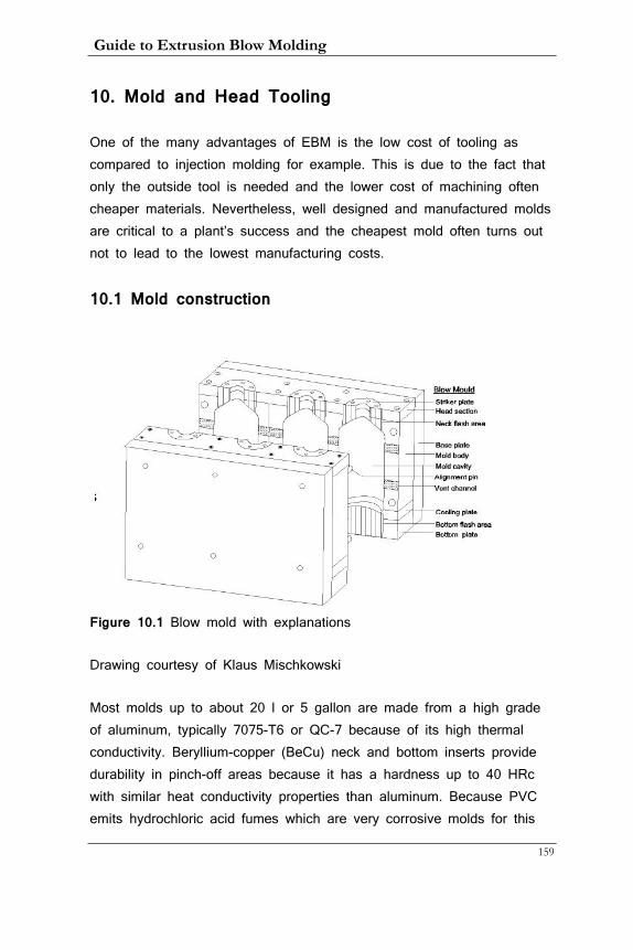
Guide to Extrusion Blow Molding
159
10. Mold and Head Tooling
One of the many advantages of EBM is the low cost of tooling as compared to injection molding for example. This is due to the fact that only the outside tool is needed and the lower cost of machining often cheaper materials. Nevertheless, well designed and manufactured molds are critical to a plant’s success and the cheapest mold often turns out not to lead to the lowest manufacturing costs.
10.1 Mold construction
Figure 10.1 Blow mold with explanations
Drawing courtesy of Klaus Mischkowski
Most molds up to about 20 l or 5 gallon are made from a high grade of aluminum, typically 7075-T6 or QC-7 because of its high thermal conductivity. Beryllium-copper (BeCu) neck and bottom inserts provide durability in pinch-off areas because it has a hardness up to 40 HRc with similar heat conductivity properties than aluminum. Because PVC emits hydrochloric acid fumes which are very corrosive molds for this
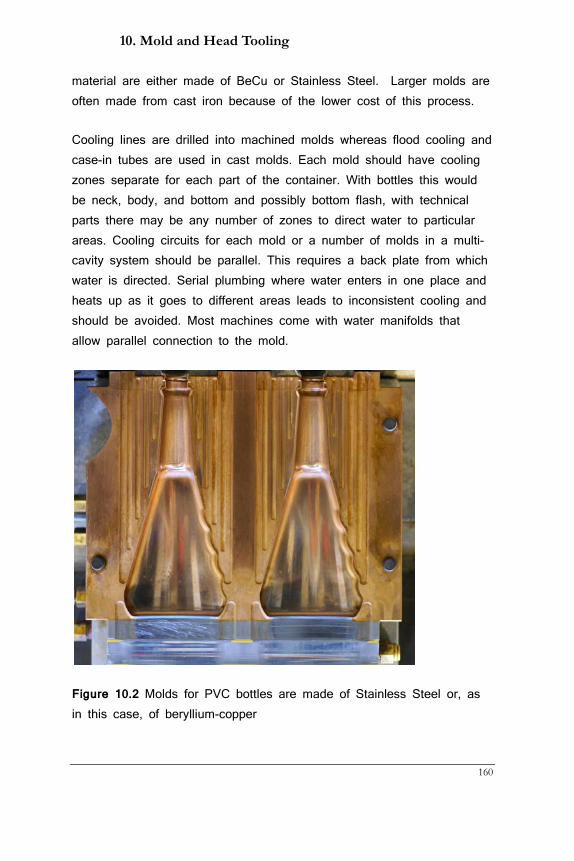
10. Mold and Head Tooling
160
material are either made of BeCu or Stainless Steel. Larger molds are often made from cast iron because of the lower cost of this process.
Cooling lines are drilled into machined molds whereas flood cooling and case-in tubes are used in cast molds. Each mold should have cooling zones separate for each part of the container. With bottles this would be neck, body, and bottom and possibly bottom flash, with technical parts there may be any number of zones to direct water to particular areas. Cooling circuits for each mold or a number of molds in a multi-cavity system should be parallel. This requires a back plate from which water is directed. Serial plumbing where water enters in one place and heats up as it goes to different areas leads to inconsistent cooling and should be avoided. Most machines come with water manifolds that allow parallel connection to the mold.
Figure 10.2 Molds for PVC bottles are made of Stainless Steel or, as in this case, of beryllium-copper
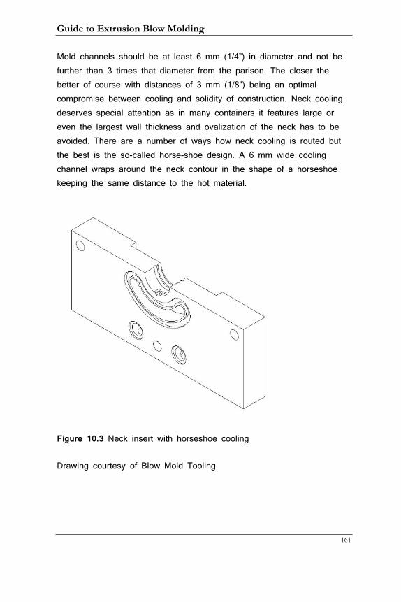
Guide to Extrusion Blow Molding
161
Mold channels should be at least 6 mm (1/4”) in diameter and not be further than 3 times that diameter from the parison. The closer the better of course with distances of 3 mm (1/8”) being an optimal compromise between cooling and solidity of construction. Neck cooling deserves special attention as in many containers it features large or even the largest wall thickness and ovalization of the neck has to be avoided. There are a number of ways how neck cooling is routed but the best is the so-called horse-shoe design. A 6 mm wide cooling channel wraps around the neck contour in the shape of a horseshoe keeping the same distance to the hot material.
Figure 10.3 Neck insert with horseshoe cooling
Drawing courtesy of Blow Mold Tooling

10. Mold and Head Tooling
162
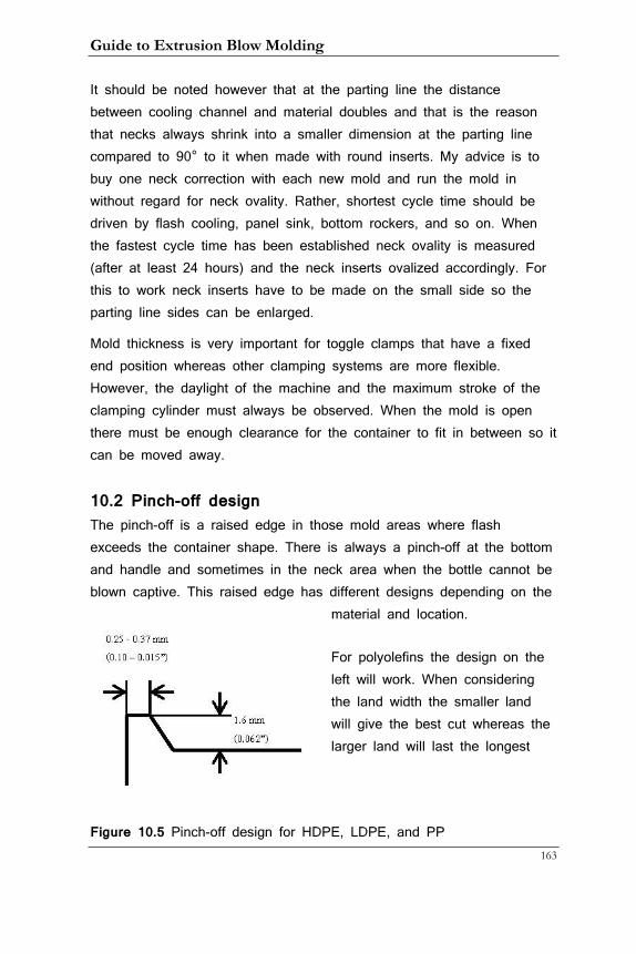
Guide to Extrusion Blow Molding
163
It should be noted however that at the parting line the distance between cooling channel and material doubles and that is the reason that necks always shrink into a smaller dimension at the parting line compared to 90° to it when made with round inserts. My advice is to buy one neck correction with each new mold and run the mold in without regard for neck ovality. Rather, shortest cycle time should be driven by flash cooling, panel sink, bottom rockers, and so on. When the fastest cycle time has been established neck ovality is measured (after at least 24 hours) and the neck inserts ovalized accordingly. For this to work neck inserts have to be made on the small side so the parting line sides can be enlarged.
Mold thickness is very important for toggle clamps that have a fixed end position whereas other clamping systems are more flexible. However, the daylight of the machine and the maximum stroke of the clamping cylinder must always be observed. When the mold is open there must be enough clearance for the container to fit in between so it can be moved away.
10.2 Pinch-off design The pinch-off is a raised edge in those mold areas where flash exceeds the container shape. There is always a pinch-off at the bottom and handle and sometimes in the neck area when the bottle cannot be blown captive. This raised edge has different designs depending on the
material and location.
For polyolefins the design on the left will work. When considering the land width the smaller land will give the best cut whereas the larger land will last the longest
Figure 10.5 Pinch-off design for HDPE, LDPE, and PP
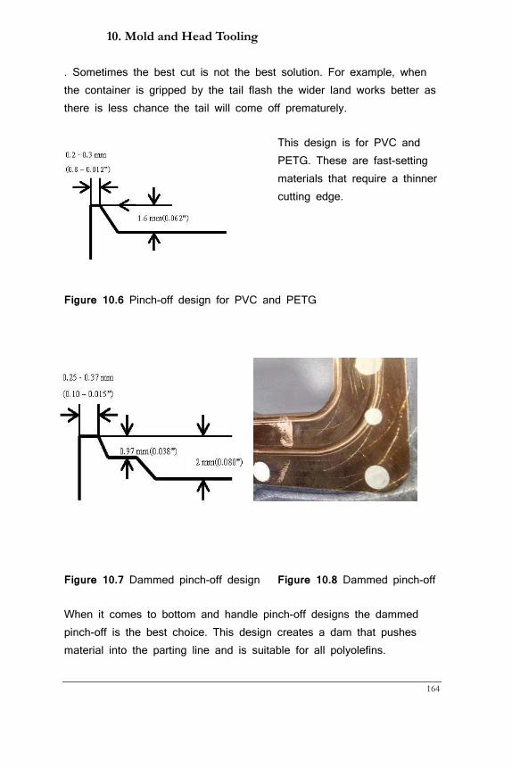
10. Mold and Head Tooling
164
. Sometimes the best cut is not the best solution. For example, when the container is gripped by the tail flash the wider land works better as there is less chance the tail will come off prematurely.
This design is for PVC and PETG. These are fast-setting materials that require a thinner cutting edge.
Figure 10.6 Pinch-off design for PVC and PETG
Figure 10.7 Dammed pinch-off design Figure 10.8 Dammed pinch-off
When it comes to bottom and handle pinch-off designs the dammed pinch-off is the best choice. This design creates a dam that pushes material into the parting line and is suitable for all polyolefins.
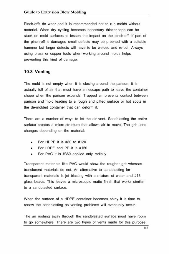
Guide to Extrusion Blow Molding
165
Pinch-offs do wear and it is recommended not to run molds without material. When dry cycling becomes necessary thicker tape can be stuck on mold surfaces to lessen the impact on the pinch-off. If part of the pinch-off is damaged small defects may be preened with a suitable hammer but larger defects will have to be welded and re-cut. Always using brass or copper tools when working around molds helps preventing this kind of damage.
10.3 Venting
The mold is not empty when it is closing around the parison; it is actually full of air that must have an escape path to leave the container shape when the parison expands. Trapped air prevents contact between parison and mold leading to a rough and pitted surface or hot spots in the de-molded container that can deform it.
There are a number of ways to let the air vent. Sandblasting the entire surface creates a micro-structure that allows air to move. The grit used changes depending on the material:
• For HDPE it is #80 to #120 • For LDPE and PP it is #150 • For PVC it is #360 applied only radially
Transparent materials like PVC would show the rougher grit whereas translucent materials do not. An alternative to sandblasting for transparent materials is jet blasting with a mixture of water and #13 glass beads. This leaves a microscopic matte finish that works similar to a sandblasted surface.
When the surface of a HDPE container becomes shiny it is time to renew the sandblasting as venting problems will eventually occur.
The air rushing away through the sandblasted surface must have room to go somewhere. There are two types of vents made for this purpose:
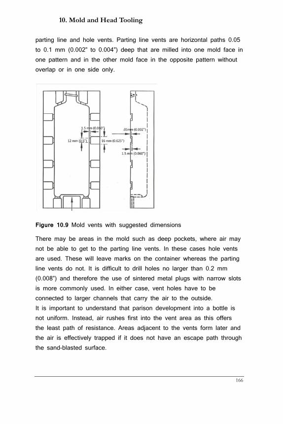
10. Mold and Head Tooling
166
parting line and hole vents. Parting line vents are horizontal paths 0.05 to 0.1 mm (0.002” to 0.004”) deep that are milled into one mold face in one pattern and in the other mold face in the opposite pattern without overlap or in one side only.
Figure 10.9 Mold vents with suggested dimensions
There may be areas in the mold such as deep pockets, where air may not be able to get to the parting line vents. In these cases hole vents are used. These will leave marks on the container whereas the parting line vents do not. It is difficult to drill holes no larger than 0.2 mm (0.008”) and therefore the use of sintered metal plugs with narrow slots is more commonly used. In either case, vent holes have to be connected to larger channels that carry the air to the outside. It is important to understand that parison development into a bottle is not uniform. Instead, air rushes first into the vent area as this offers the least path of resistance. Areas adjacent to the vents form later and the air is effectively trapped if it does not have an escape path through the sand-blasted surface.
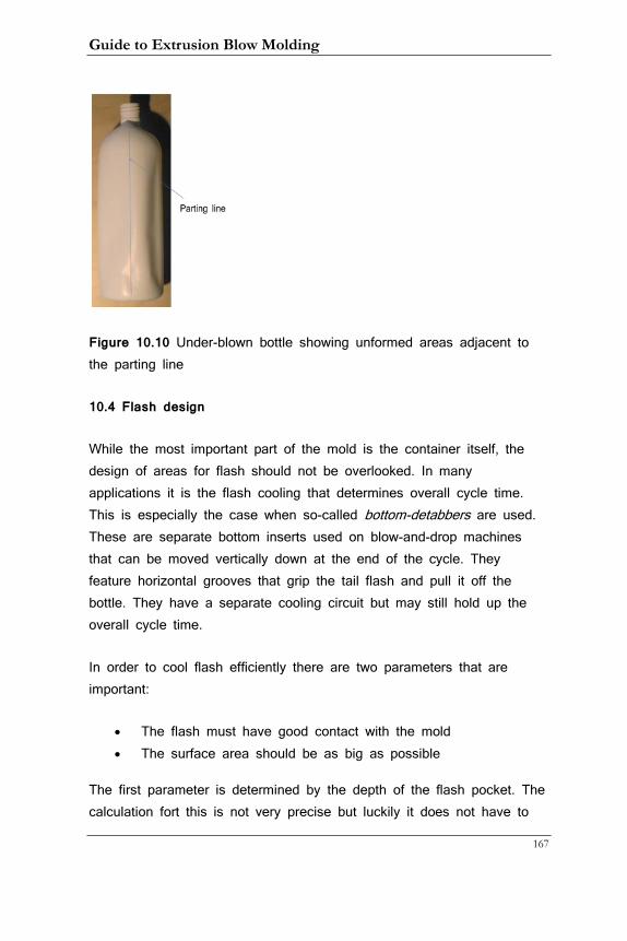
Guide to Extrusion Blow Molding
167
Figure 10.10 Under-blown bottle showing unformed areas adjacent to the parting line
10.4 Flash design
While the most important part of the mold is the container itself, the design of areas for flash should not be overlooked. In many applications it is the flash cooling that determines overall cycle time. This is especially the case when so-called bottom-detabbers are used. These are separate bottom inserts used on blow-and-drop machines that can be moved vertically down at the end of the cycle. They feature horizontal grooves that grip the tail flash and pull it off the bottle. They have a separate cooling circuit but may still hold up the overall cycle time.
In order to cool flash efficiently there are two parameters that are important:
• The flash must have good contact with the mold • The surface area should be as big as possible
The first parameter is determined by the depth of the flash pocket. The calculation fort this is not very precise but luckily it does not have to
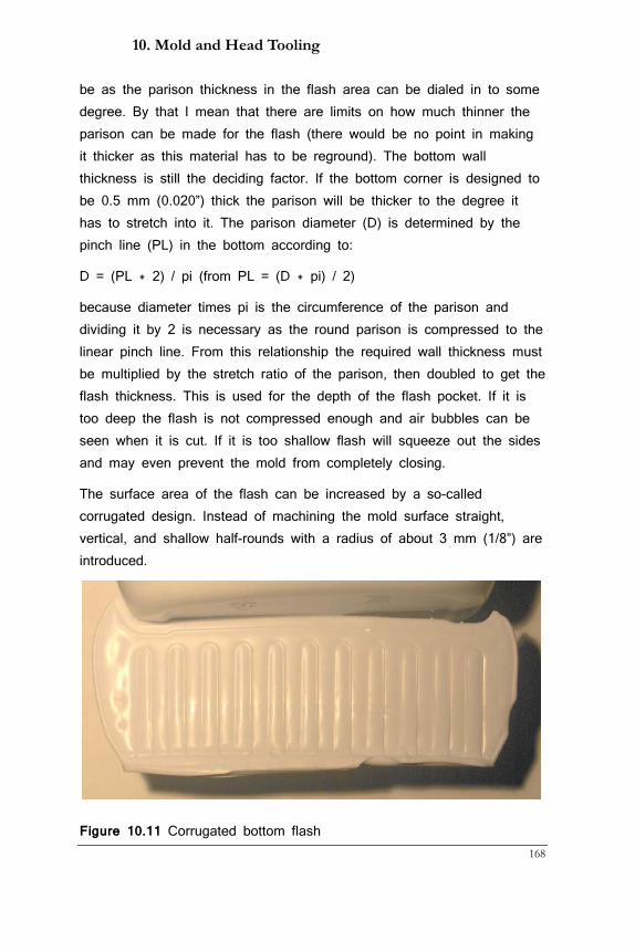
10. Mold and Head Tooling
168
be as the parison thickness in the flash area can be dialed in to some degree. By that I mean that there are limits on how much thinner the parison can be made for the flash (there would be no point in making it thicker as this material has to be reground). The bottom wall thickness is still the deciding factor. If the bottom corner is designed to be 0.5 mm (0.020”) thick the parison will be thicker to the degree it has to stretch into it. The parison diameter (D) is determined by the pinch line (PL) in the bottom according to:
D = (PL * 2) / pi (from PL = (D * pi) / 2)
because diameter times pi is the circumference of the parison and dividing it by 2 is necessary as the round parison is compressed to the linear pinch line. From this relationship the required wall thickness must be multiplied by the stretch ratio of the parison, then doubled to get the flash thickness. This is used for the depth of the flash pocket. If it is too deep the flash is not compressed enough and air bubbles can be seen when it is cut. If it is too shallow flash will squeeze out the sides and may even prevent the mold from completely closing.
The surface area of the flash can be increased by a so-called corrugated design. Instead of machining the mold surface straight, vertical, and shallow half-rounds with a radius of about 3 mm (1/8”) are introduced.
Figure 10.11 Corrugated bottom flash
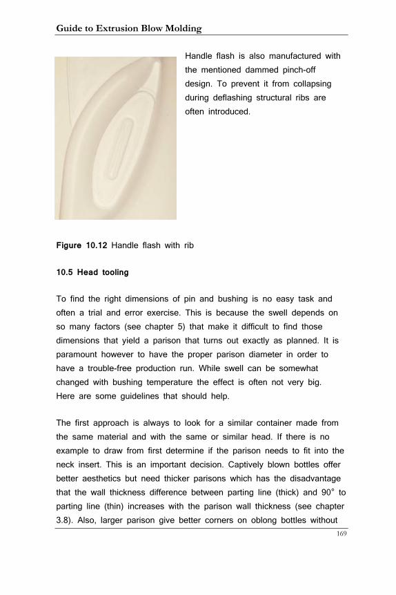
Guide to Extrusion Blow Molding
169
Handle flash is also manufactured with the mentioned dammed pinch-off design. To prevent it from collapsing during deflashing structural ribs are often introduced.
Figure 10.12 Handle flash with rib
10.5 Head tooling
To find the right dimensions of pin and bushing is no easy task and often a trial and error exercise. This is because the swell depends on so many factors (see chapter 5) that make it difficult to find those dimensions that yield a parison that turns out exactly as planned. It is paramount however to have the proper parison diameter in order to have a trouble-free production run. While swell can be somewhat changed with bushing temperature the effect is often not very big. Here are some guidelines that should help.
The first approach is always to look for a similar container made from the same material and with the same or similar head. If there is no example to draw from first determine if the parison needs to fit into the neck insert. This is an important decision. Captively blown bottles offer better aesthetics but need thicker parisons which has the disadvantage that the wall thickness difference between parting line (thick) and 90° to parting line (thin) increases with the parison wall thickness (see chapter 3.8). Also, larger parison give better corners on oblong bottles without
10. Mold and Head Tooling
170
ovalization. Therefore, the choice of parison diameter should be taken after looking at these parameters. As a ballpark rule the bushing diameter should be half of the inside neck diameter when the parison needs to fit into the neck.
Once a parison diameter has been determined measure the pinch line of other bottles of the same material and calculate their parison diameter according to the formula in the preceding chapter. This will enable you to calculate their swell when you compare it to the bushing diameter. If it is a new material you will have to rely on the specifications of the material supplier and start with the middle of the range they specify. As to weight swell, parison thickness can be calculated by dividing the flash thickness by 2.
Once a bushing diameter has been determined the question of converging or diverging tooling needs to be answered. It is best to follow the example of other, similar bottles as swell also depends on the type of tooling. There is no fixed rule what tooling is best suited for each bottle but it is clear that bushing diameters below 50 mm (2”) will be converging as there is simply no room for a “mushroom”-type diverging bushing. When designing converging tooling it is important that the pin always extends from the bushing or is at least flush with it. Otherwise, control over the parison is lost.
Now the pin diameter needs to be calculated. This in turn depends on the desired wall thickness of the parison which depends on the desired wall thickness of the container. This can be calculated with some accuracy by comparing the diameter or large width of an oblong container to the chosen bushing diameter and back calculating how thick the parison needs to be to yield a minimum wall thickness. Weight swell is again material dependent and often 200%. This means that if the parison wall thickness should be 2.5 mm (0.098”) the die gap should be half of that number.
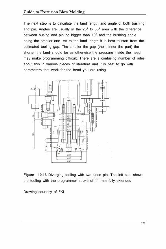
Guide to Extrusion Blow Molding
171
The next step is to calculate the land length and angle of both bushing and pin. Angles are usually in the 25° to 35° area with the difference between busing and pin no bigger than 10° and the bushing angle being the smaller one. As to the land length it is best to start from the estimated tooling gap. The smaller the gap (the thinner the part) the shorter the land should be as otherwise the pressure inside the head may make programming difficult. There are a confusing number of rules about this in various pieces of literature and it is best to go with parameters that work for the head you are using.
Figure 10.13 Diverging tooling with two-piece pin. The left side shows the tooling with the programmer stroke of 11 mm fully extended
Drawing courtesy of FKI
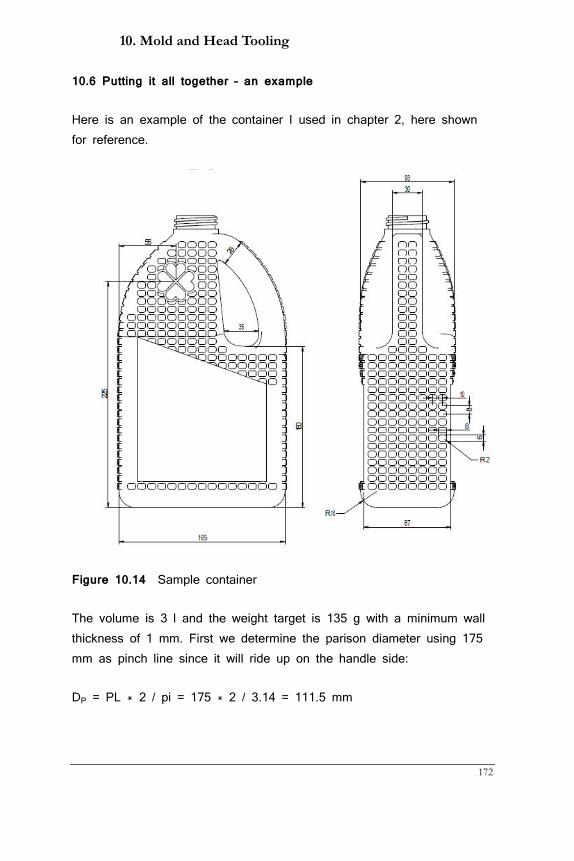
10. Mold and Head Tooling
172
10.6 Putting it all together – an example
Here is an example of the container I used in chapter 2, here shown for reference.
Figure 10.14 Sample container
The volume is 3 l and the weight target is 135 g with a minimum wall thickness of 1 mm. First we determine the parison diameter using 175 mm as pinch line since it will ride up on the handle side:
DP = PL * 2 / pi = 175 * 2 / 3.14 = 111.5 mm
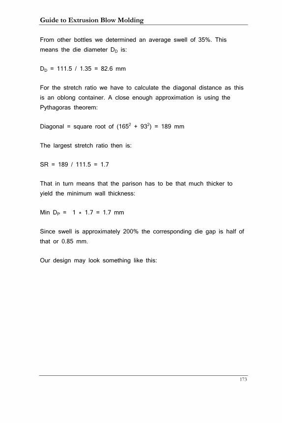
Guide to Extrusion Blow Molding
173
From other bottles we determined an average swell of 35%. This means the die diameter DD is:
DD = 111.5 / 1.35 = 82.6 mm
For the stretch ratio we have to calculate the diagonal distance as this is an oblong container. A close enough approximation is using the Pythagoras theorem:
Diagonal = square root of (1652 + 932) = 189 mm
The largest stretch ratio then is:
SR = 189 / 111.5 = 1.7
That in turn means that the parison has to be that much thicker to yield the minimum wall thickness:
Min DP = 1 * 1.7 = 1.7 mm
Since swell is approximately 200% the corresponding die gap is half of that or 0.85 mm.
Our design may look something like this:
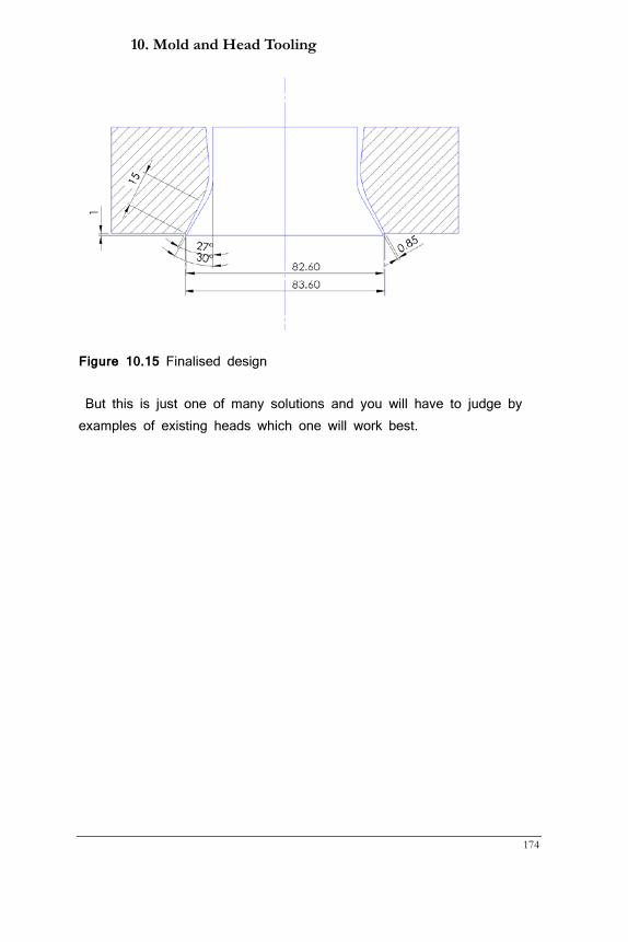
10. Mold and Head Tooling
174
Figure 10.15 Finalised design
But this is just one of many solutions and you will have to judge by examples of existing heads which one will work best.
Guide to Extrusion Blow Molding
175
11. Container Design Considerations
This chapter was written with material from my good friend Ed Campbell who passed away in early 2013. In memoriam.
11.1 Design process Any container design must take into account three main requirements:
• The container must be moldable
• It must pass through filling and distribution systems efficiently
• It must please consumers so they will buy it
The actual design process can be very different from company to company. Sometimes marketing people work with consumer focus groups to test mock-ups or actual samples, other times a design engineer is given a sketch on a napkin. Either way, the path from an idea to a finished design will go through several steps and more than one person will have input. With the advent of 3-D CAD design software it has become easier to create and critique screen models before any samples have to be made. At this point blow mold experts should be consulted as to whether a given design can be molded and at what cost. Marketing people generally do not know that much about the process and often unintentionally add unnecessary complications.
Once a design has been approved on-screen the design can go two ways:
• Have a sample mold made and produce 100 or so containers • Create a physical model through 3-D printing or similar
The samples from an actual process are much better as they have the right feel and touch but are of course more expensive and time-consuming to produce. Most companies produce a cheaper model first be it through 3-D printing that is very cost-effective or stereo lithography, thermoforming with wooden molds or similar. From here on
11. Container Design Considerations
176
input from various groups within a company may lead to changes in design. Further engineering like Finite Element Analysis (FEA) may also force changes. For example, with FEA it is now possible to get a very good estimate on top-load and a design can be refined by adding structural components to improve on that if necessary.
11.2 Design considerations
There are a number of applications that all have their own specific requirements:
• Automotive has very stringent quality requirements with some
parts having to last millions of usage cycles
• Personal/cosmetic has mostly tight aesthetic requirements
• Food items fall under FDA rules in the US and plant operations
can be inspected
• Medical also has stringent rules; only certain materials are
allowed and often no regrind can be used
• Household and agricultural chemicals often demand specific
barrier performance and safety of use obligations
• Hazardous goods fall under the oversight of various government
agencies and UN certification is usually a must
Designers must be aware of these restrictions before they ever start their CAD program. Other considerations come then into play:
• Blow ratios:
o Parison must fit into neck (captive blow) or neck flash
is allowed
o Parison diameter to container diameter/width
o Handle width to thickness ratio (should be 1:1)
• Draft angles:
o Shoulder angle (15° minimum for best top load)
Guide to Extrusion Blow Molding
177
o Parting line should be 5°
o Handle eye for trimming should be ~10° to allow easy
adjustment of deflash or punch
• Undercuts
o First rule: no undercuts without moving mold inserts
o Bottom push-up is an undercut and should be deep
enough to avoid rocker bottoms but not too deep to
cause thin bottom corners (3 mm or 1/8” minimum)
• Engravings
o Maximum depth 0.4 mm (0.015”) (deeper engravings
may cause bottle to stick in mold)
o No engraving on parting line
o Useful to mask surface defects
• Drop impact
o High impact strength: HDPE, LDPE, PET, PC
o Low impact strength: PP, PVC, EPET
o Large base radii critical
o Cold or hot environment has major influence on
performance
• Hot-filling
o PP is best suited
o Controlling distortion is better than increasing wall
thickness to prevent container collapse
o Short, stubby containers perform better than tall ones
• Microwave use
o Bottle must fit into microwave oven
o Head space must be big enough to prevent over-boiling
o Grip or handle area should not get hot
o Shape must facilitate uniform heating
• Closure selection
11. Container Design Considerations
178
o Closure must be selected first and the neck must
accommodate it
o SPI neck finish, snap, or special
o Type of sealing; liner or plug seal
o Child resistant closure may need special neck
configuration
• Top load
o Static load on lowest grid on pallet
o Dynamic load in distribution
o Loading during filling and capping
o Calculation of how much load the corrugated will share
• Decorating options
o Many decorating machines need bottle orientation via
lugs in bottle base
o Silk screening and labeling need straight walls
o Pad printing allows decoration of curved surfaces
o Shrink sleeves may require particular bottom corners
o Embossing or debossing can be an alternative
• Choice of resin has major impact on container performance
o Impact strength
o Clarity and gloss
o Maximum fill temperature
o Stiffness/squeezability
o Barrier against water or solvent loss and oxygen
ingress
o Stress crack resistance
o Taste and odor
o Compatibility with product
Taking all considerations into account greatly assists a smooth
design process!
Guide to Extrusion Blow Molding
179
12. Quality
There are three reasons why the EBM process is less stable than other processes:
• Only the outside of the container is fixed with a metal mold
• Most plants do not control the climate, i.e. temperature,
humidity, and pressure which are parameters that can have an
impact on the process
• There are quite a number of process variables that defy easy
and consistent control such as
o Head support air variations
o Sagging
o Cutting and moving the carriage
o Deflashing
It is therefore important that quality measures are in place that take the real process into account. It is also well known that some applications have a smaller process window than others and these measures should be adjusted. Many times however quality procedures are rigid instead of flexible and this can lead to wasted time or unnecessary scrap.
12.1 Sampling Interval and Responsibility
There are enormous differences in who does what and when in the industry. In some companies only quality personnel test bottles, in others operators share the work load with them. Sampling intervals range from 2 to 12 hours with different procedures in place what to do when containers are outside specifications. Here are some suggestions from my experience:
Operators and setup personnel should do initial testing to reduce the time between when the machine starts or re-starts and the green light
12. Container Quality
180
for production is given. Operators should weigh the bottles and check neck dimensions and minimum wall thickness. For this to work they need to have a bottle drawing with those numbers and the means to make the checks, i.e. a scale, calipers, and a wall thickness measurement instrument. Since the latter is rather expensive, it should be shared on the floor. This approach will take time away from floor people that they would otherwise spend on the machine but the advantage is that they can immediately correct any problems they encounter rather than waiting for a quality person to tell them.
As to sampling intervals it should depend on how well the process runs. Maybe using a classification system of very stable, medium stable, and unstable will help determine how often samples should be taken. While it is always the goal to create a wide and robust process window it is often not realistic to expect setup people spending hours of trial and error to get there when the whole run only lasts for a day or two. The state of the machine plays a role here as well as newer machines generally run more consistently. Therefore, an unstable process should be sampled every two hours, a medium stable process every 4 to 6 hours, a very stable one every 8 to 12 hours. When long sampling times are in place operators need to check certain parameters like weight every few hours; the long interval is to reduce frequency of thorough and time-consuming testing.
Sampling is critical as the next question is what to do when one parameter is outside specifications. The quality person should alert the operator immediately of the problem rather than waiting until testing of all bottles has been done. All containers starting from the last tested and good bottles must be quarantined. This of course requires that each box or pallet has a label with a time stamp. Next, the severity of the problem must be discussed while the operator is making the necessary machine adjustments to bring the container back into specifications. If the defect is so severe that bottles cannot be shipped then there is a choice between sorting and regrinding, neither of which
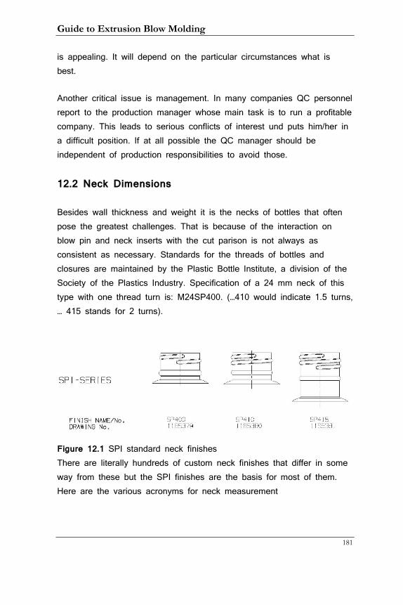
Guide to Extrusion Blow Molding
181
is appealing. It will depend on the particular circumstances what is best.
Another critical issue is management. In many companies QC personnel report to the production manager whose main task is to run a profitable company. This leads to serious conflicts of interest und puts him/her in a difficult position. If at all possible the QC manager should be independent of production responsibilities to avoid those.
12.2 Neck Dimensions
Besides wall thickness and weight it is the necks of bottles that often pose the greatest challenges. That is because of the interaction on blow pin and neck inserts with the cut parison is not always as consistent as necessary. Standards for the threads of bottles and closures are maintained by the Plastic Bottle Institute, a division of the Society of the Plastics Industry. Specification of a 24 mm neck of this type with one thread turn is: M24SP400. (…410 would indicate 1.5 turns, … 415 stands for 2 turns).
Figure 12.1 SPI standard neck finishes There are literally hundreds of custom neck finishes that differ in some way from these but the SPI finishes are the basis for most of them. Here are the various acronyms for neck measurement
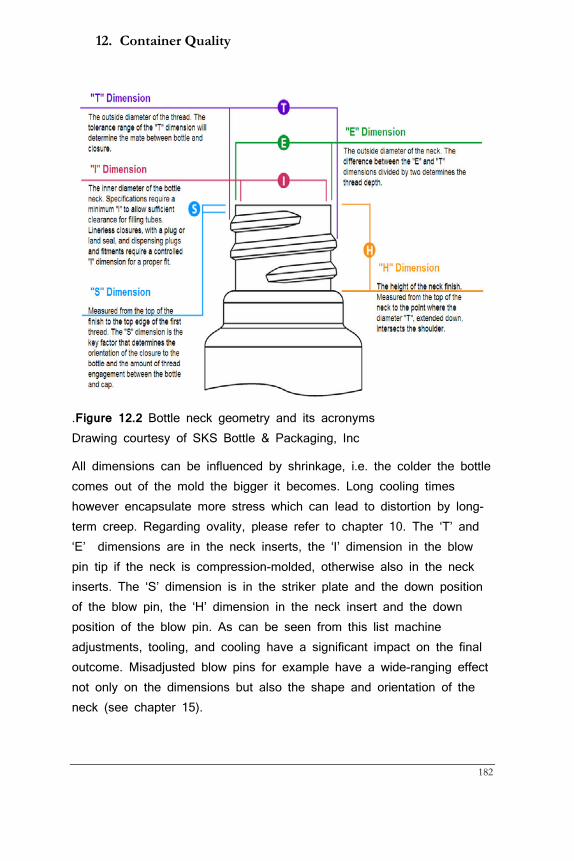
12. Container Quality
182
.Figure 12.2 Bottle neck geometry and its acronyms Drawing courtesy of SKS Bottle & Packaging, Inc
All dimensions can be influenced by shrinkage, i.e. the colder the bottle comes out of the mold the bigger it becomes. Long cooling times however encapsulate more stress which can lead to distortion by long-term creep. Regarding ovality, please refer to chapter 10. The ‘T’ and ‘E’ dimensions are in the neck inserts, the ‘I’ dimension in the blow pin tip if the neck is compression-molded, otherwise also in the neck inserts. The ‘S’ dimension is in the striker plate and the down position of the blow pin, the ‘H’ dimension in the neck insert and the down position of the blow pin. As can be seen from this list machine adjustments, tooling, and cooling have a significant impact on the final outcome. Misadjusted blow pins for example have a wide-ranging effect not only on the dimensions but also the shape and orientation of the neck (see chapter 15).
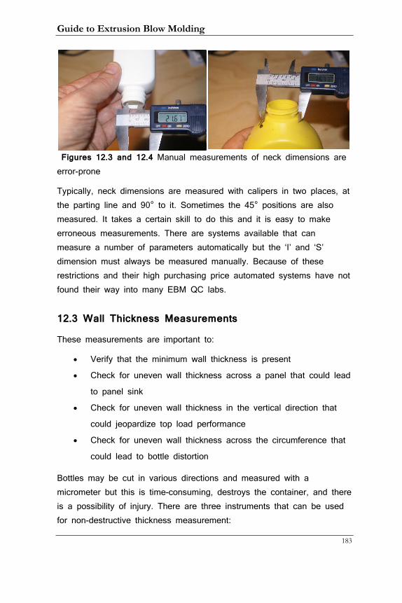
Guide to Extrusion Blow Molding
183
Figures 12.3 and 12.4 Manual measurements of neck dimensions are error-prone
Typically, neck dimensions are measured with calipers in two places, at the parting line and 90° to it. Sometimes the 45° positions are also measured. It takes a certain skill to do this and it is easy to make erroneous measurements. There are systems available that can measure a number of parameters automatically but the ‘I’ and ‘S’ dimension must always be measured manually. Because of these restrictions and their high purchasing price automated systems have not found their way into many EBM QC labs.
12.3 Wall Thickness Measurements
These measurements are important to:
• Verify that the minimum wall thickness is present
• Check for uneven wall thickness across a panel that could lead
to panel sink
• Check for uneven wall thickness in the vertical direction that
could jeopardize top load performance
• Check for uneven wall thickness across the circumference that
could lead to bottle distortion
Bottles may be cut in various directions and measured with a micrometer but this is time-consuming, destroys the container, and there is a possibility of injury. There are three instruments that can be used for non-destructive thickness measurement:
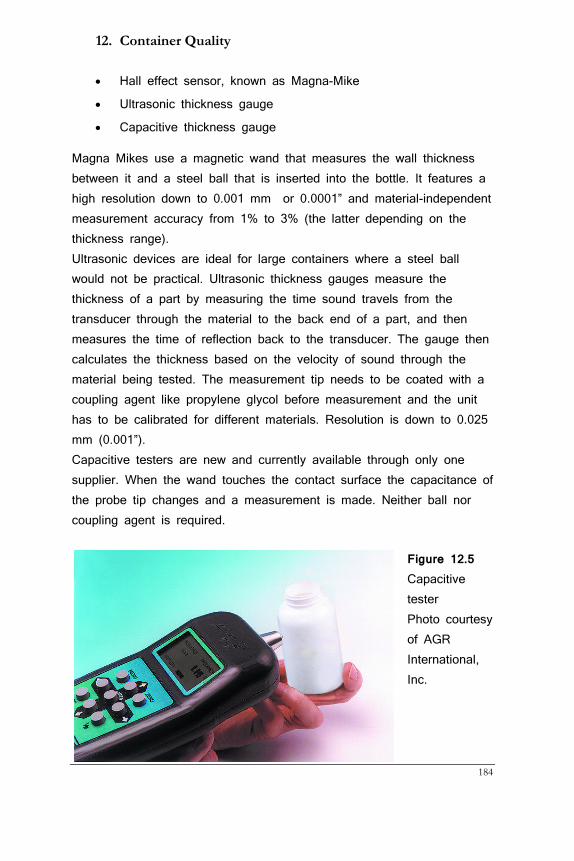
12. Container Quality
184
• Hall effect sensor, known as Magna-Mike
• Ultrasonic thickness gauge
• Capacitive thickness gauge
Magna Mikes use a magnetic wand that measures the wall thickness between it and a steel ball that is inserted into the bottle. It features a high resolution down to 0.001 mm or 0.0001” and material-independent measurement accuracy from 1% to 3% (the latter depending on the thickness range). Ultrasonic devices are ideal for large containers where a steel ball would not be practical. Ultrasonic thickness gauges measure the thickness of a part by measuring the time sound travels from the transducer through the material to the back end of a part, and then measures the time of reflection back to the transducer. The gauge then calculates the thickness based on the velocity of sound through the material being tested. The measurement tip needs to be coated with a coupling agent like propylene glycol before measurement and the unit has to be calibrated for different materials. Resolution is down to 0.025 mm (0.001”). Capacitive testers are new and currently available through only one supplier. When the wand touches the contact surface the capacitance of the probe tip changes and a measurement is made. Neither ball nor coupling agent is required.
Figure 12.5 Capacitive tester Photo courtesy of AGR International, Inc.
Guide to Extrusion Blow Molding
185
12.4 Drop Test
Many containers must undergo a test to verify they do not break when dropped from a certain height. Typical heights are 1 to 1.5 m (3’ to 5’) and often the water temperature of the test bottle is specified to simulate temperatures in a refrigerator (around 4°C or 39°F). A simple test apparatus is available from several sources.
Containers made from polyolefins break mostly in the weakest corner or the bottom seam. The specification of a minimum wall thickness guards against this failure and therefore must be paid attention to.
12.5 Top Load Test
Containers are often stacked on pallets and the bottom layer of each stack must be able to carry the load of the containers above them. The bigger the footprint of the container the fewer containers can be placed in one layer and the more top load they must carry. Top load requirements are therefore dependent on container size and stack height as well as the density of the product. A tester has been developed that uses a load cell on a motorized column. The container is placed centered to the cell and the cell moved towards it. Most companies specify a speed of 13mm (0.5”)/minute. Bottles will start contracting as the pressure increases and eventually buckle. At this moment the measured force becomes very small and the value before the buckling occurs is typically the peak and test result. Simple testers just log this peak pressure but there are more sophisticated machines that allow graphing the pressure curve.
Unfortunately, the top load requirements given to converters are often not scientifically explored. While it is easy to calculate the static load there is an uncertainty about the dynamic forces the bottom layer experiences when the truck carrying the filled containers goes over a pothole for example. When containers are shipped in boxes it is also not foreseeable how much of the load the carton will carry. Margins of
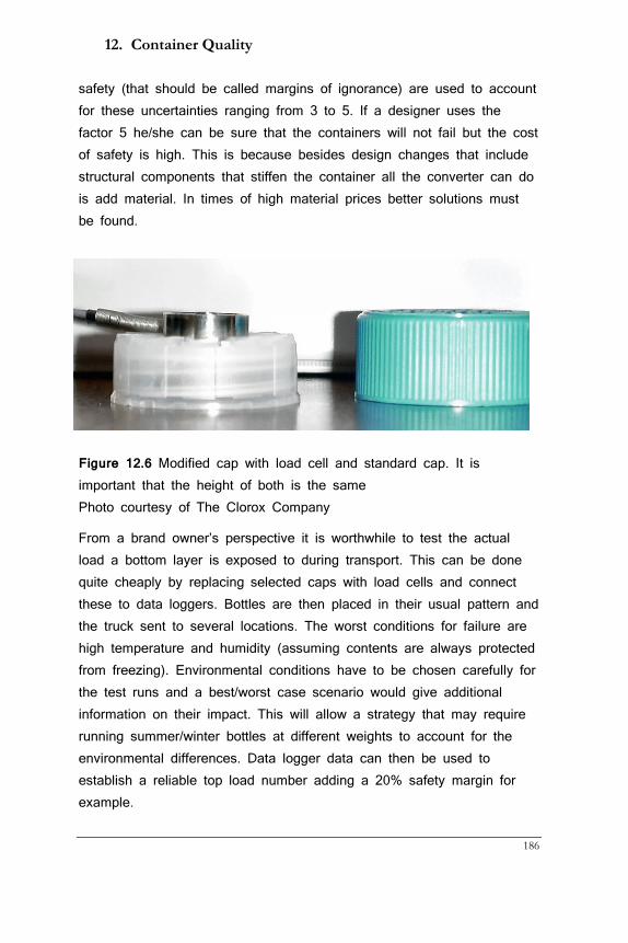
12. Container Quality
186
safety (that should be called margins of ignorance) are used to account for these uncertainties ranging from 3 to 5. If a designer uses the factor 5 he/she can be sure that the containers will not fail but the cost of safety is high. This is because besides design changes that include structural components that stiffen the container all the converter can do is add material. In times of high material prices better solutions must be found.
Figure 12.6 Modified cap with load cell and standard cap. It is important that the height of both is the same Photo courtesy of The Clorox Company
From a brand owner’s perspective it is worthwhile to test the actual load a bottom layer is exposed to during transport. This can be done quite cheaply by replacing selected caps with load cells and connect these to data loggers. Bottles are then placed in their usual pattern and the truck sent to several locations. The worst conditions for failure are high temperature and humidity (assuming contents are always protected from freezing). Environmental conditions have to be chosen carefully for the test runs and a best/worst case scenario would give additional information on their impact. This will allow a strategy that may require running summer/winter bottles at different weights to account for the environmental differences. Data logger data can then be used to establish a reliable top load number adding a 20% safety margin for example.
Guide to Extrusion Blow Molding
187
From a converter’s perspective it is important that the operator understands where the container buckles. He/she can then add material to this area taking it away from other areas that do not need it. This allows to get better top load values without adding container weight overall. Of course, one must keep the minimum wall thickness in mind when doing this kind of fine-tuning.
12.6 UN Testing Containers that are produced to carry hazardous goods must have a UN certification that is administered by the local transport safety agencies. In the US this is the Department of Transportation (DOT). Regulatory agencies decide what is considered hazardous and converters that deal in chemicals will be aware of regulations. UN certification is a lengthy and costly process and must be taken very seriously as even small mistakes can cost a lot of money. Here is a list of the various tests that containers must undergo in a certified laboratory:
• Dynamic top load test
• 28-day stack test for new submissions
• Hydro-static (leak) test at a specified pressure
• Drop test after containers were filled with anti-freeze and
cooled for 48 hours at -18° C (-28°F). Drop test height
depends on the packing group classification
• Determination of all relevant thickness values and weight
The certificate must be renewed every year or when changes such as a new mold or resin have occurred. It is important to understand that the lab will not concern itself with average wall thickness and weight values but with minima. Typically a container is measured at the top, several body locations, bottom, and all radii. The minimum thicknesses at these locations become the legal minima should the containers pass. This means that it is illegal to sell containers that have thicknesses below these minima. For this reason, containers must be run in production with about 10% higher weight
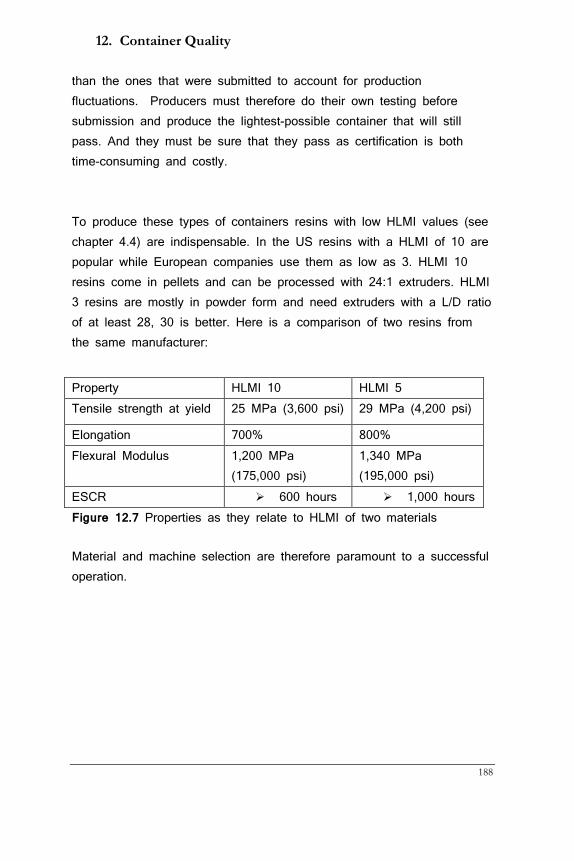
12. Container Quality
188
than the ones that were submitted to account for production fluctuations. Producers must therefore do their own testing before submission and produce the lightest-possible container that will still pass. And they must be sure that they pass as certification is both time-consuming and costly. To produce these types of containers resins with low HLMI values (see chapter 4.4) are indispensable. In the US resins with a HLMI of 10 are popular while European companies use them as low as 3. HLMI 10 resins come in pellets and can be processed with 24:1 extruders. HLMI 3 resins are mostly in powder form and need extruders with a L/D ratio of at least 28, 30 is better. Here is a comparison of two resins from the same manufacturer:
Figure 12.7 Properties as they relate to HLMI of two materials
Material and machine selection are therefore paramount to a successful operation.
Property HLMI 10 HLMI 5 Tensile strength at yield 25 MPa (3,600 psi) 29 MPa (4,200 psi)
Elongation 700% 800% Flexural Modulus 1,200 MPa
(175,000 psi) 1,340 MPa (195,000 psi)
ESCR 600 hours 1,000 hours
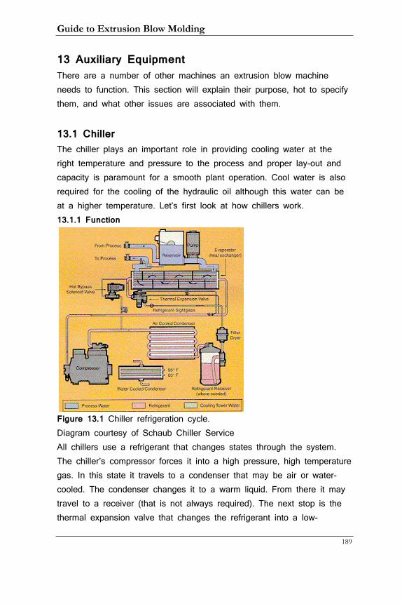
Guide to Extrusion Blow Molding
189
13 Auxiliary Equipment There are a number of other machines an extrusion blow machine needs to function. This section will explain their purpose, hot to specify them, and what other issues are associated with them.
13.1 Chiller The chiller plays an important role in providing cooling water at the right temperature and pressure to the process and proper lay-out and capacity is paramount for a smooth plant operation. Cool water is also required for the cooling of the hydraulic oil although this water can be at a higher temperature. Let’s first look at how chillers work. 13.1.1 Function
Figure 13.1 Chiller refrigeration cycle. Diagram courtesy of Schaub Chiller Service All chillers use a refrigerant that changes states through the system. The chiller’s compressor forces it into a high pressure, high temperature gas. In this state it travels to a condenser that may be air or water-cooled. The condenser changes it to a warm liquid. From there it may travel to a receiver (that is not always required). The next stop is the thermal expansion valve that changes the refrigerant into a low-
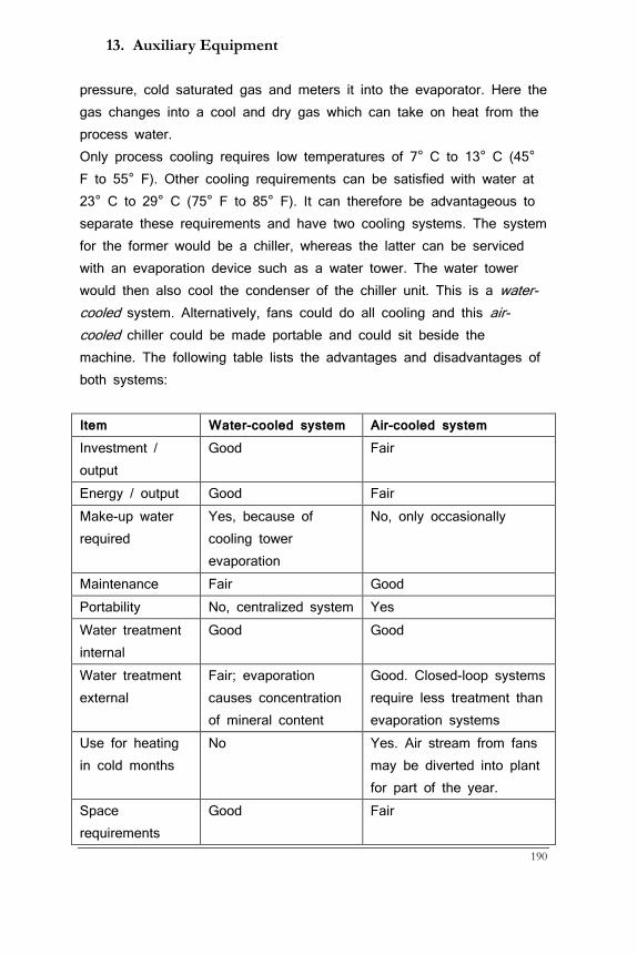
13. Auxiliary Equipment
190
pressure, cold saturated gas and meters it into the evaporator. Here the gas changes into a cool and dry gas which can take on heat from the process water. Only process cooling requires low temperatures of 7° C to 13° C (45° F to 55° F). Other cooling requirements can be satisfied with water at 23° C to 29° C (75° F to 85° F). It can therefore be advantageous to separate these requirements and have two cooling systems. The system for the former would be a chiller, whereas the latter can be serviced with an evaporation device such as a water tower. The water tower would then also cool the condenser of the chiller unit. This is a water-cooled system. Alternatively, fans could do all cooling and this air-cooled chiller could be made portable and could sit beside the machine. The following table lists the advantages and disadvantages of both systems: Item Water-cooled system Air-cooled system Investment / output
Good Fair
Energy / output Good Fair Make-up water required
Yes, because of cooling tower evaporation
No, only occasionally
Maintenance Fair Good Portability No, centralized system Yes Water treatment internal
Good Good
Water treatment external
Fair; evaporation causes concentration of mineral content
Good. Closed-loop systems require less treatment than evaporation systems
Use for heating in cold months
No Yes. Air stream from fans may be diverted into plant for part of the year.
Space requirements
Good Fair
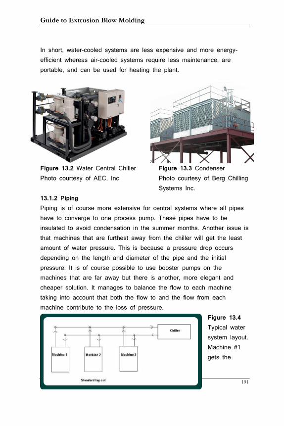
Guide to Extrusion Blow Molding
191
In short, water-cooled systems are less expensive and more energy-efficient whereas air-cooled systems require less maintenance, are portable, and can be used for heating the plant.
Figure 13.2 Water Central Chiller Figure 13.3 Condenser Photo courtesy of AEC, Inc Photo courtesy of Berg Chilling
Systems Inc. 13.1.2 Piping Piping is of course more extensive for central systems where all pipes have to converge to one process pump. These pipes have to be insulated to avoid condensation in the summer months. Another issue is that machines that are furthest away from the chiller will get the least amount of water pressure. This is because a pressure drop occurs depending on the length and diameter of the pipe and the initial pressure. It is of course possible to use booster pumps on the machines that are far away but there is another, more elegant and cheaper solution. It manages to balance the flow to each machine taking into account that both the flow to and the flow from each machine contribute to the loss of pressure.
Figure 13.4 Typical water system layout. Machine #1 gets the
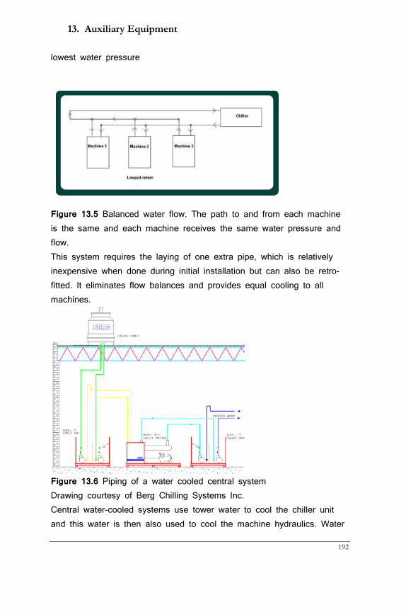
13. Auxiliary Equipment
192
lowest water pressure
Figure 13.5 Balanced water flow. The path to and from each machine is the same and each machine receives the same water pressure and flow. This system requires the laying of one extra pipe, which is relatively inexpensive when done during initial installation but can also be retro-fitted. It eliminates flow balances and provides equal cooling to all machines.
Figure 13.6 Piping of a water cooled central system Drawing courtesy of Berg Chilling Systems Inc. Central water-cooled systems use tower water to cool the chiller unit and this water is then also used to cool the machine hydraulics. Water

Guide to Extrusion Blow Molding
193
towers are always outside where a stream of water is cascading from top to bottom and evaporation cooling takes place. This is the same underlying principle how sweat on skin contributes to body cooling. Heat generation is limited to the heat that is created in the compressor.
Figure 13.7 Piping of an air-cooled system Drawing courtesy of Berg Chilling Systems Inc. Air-cooled chillers work with fans and are usually placed beside the machine and can be used to control water temperature for each machine individually, which can be an advantage in the summer months. The piping drawing above shows how the exhaust pipe of the chiller can be mounted to allow hot air discharge to the plant in the winter and to the outside in the summer. Plants that work 24/7 are usually warm enough in moderate climates but plants that shut down over a weekend may well take advantage of the free heating of their chillers.
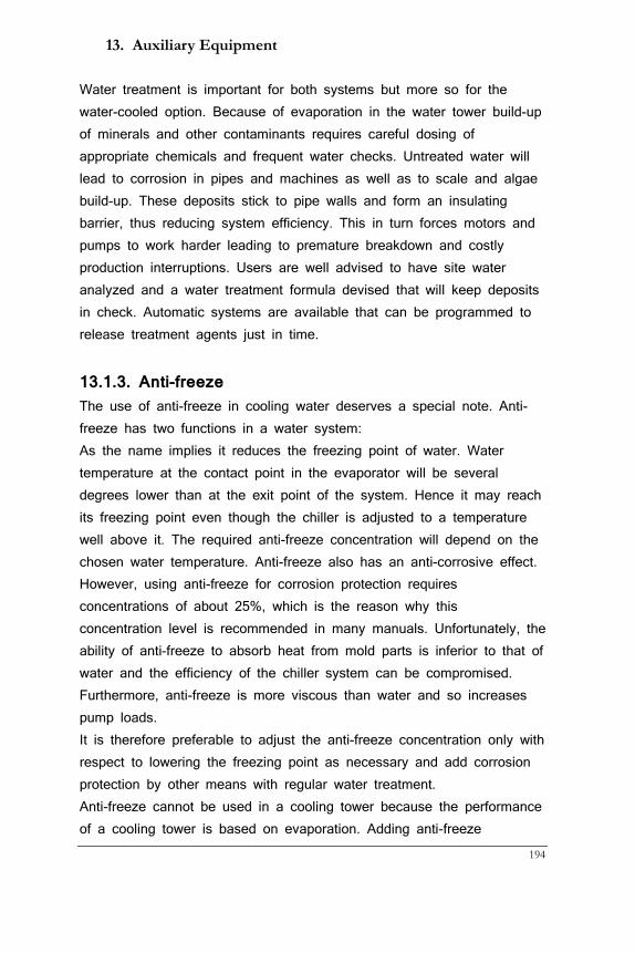
13. Auxiliary Equipment
194
Water treatment is important for both systems but more so for the water-cooled option. Because of evaporation in the water tower build-up of minerals and other contaminants requires careful dosing of appropriate chemicals and frequent water checks. Untreated water will lead to corrosion in pipes and machines as well as to scale and algae build-up. These deposits stick to pipe walls and form an insulating barrier, thus reducing system efficiency. This in turn forces motors and pumps to work harder leading to premature breakdown and costly production interruptions. Users are well advised to have site water analyzed and a water treatment formula devised that will keep deposits in check. Automatic systems are available that can be programmed to release treatment agents just in time.
13.1.3. Anti-freeze The use of anti-freeze in cooling water deserves a special note. Anti-freeze has two functions in a water system: As the name implies it reduces the freezing point of water. Water temperature at the contact point in the evaporator will be several degrees lower than at the exit point of the system. Hence it may reach its freezing point even though the chiller is adjusted to a temperature well above it. The required anti-freeze concentration will depend on the chosen water temperature. Anti-freeze also has an anti-corrosive effect. However, using anti-freeze for corrosion protection requires concentrations of about 25%, which is the reason why this concentration level is recommended in many manuals. Unfortunately, the ability of anti-freeze to absorb heat from mold parts is inferior to that of water and the efficiency of the chiller system can be compromised. Furthermore, anti-freeze is more viscous than water and so increases pump loads. It is therefore preferable to adjust the anti-freeze concentration only with respect to lowering the freezing point as necessary and add corrosion protection by other means with regular water treatment. Anti-freeze cannot be used in a cooling tower because the performance of a cooling tower is based on evaporation. Adding anti-freeze
Guide to Extrusion Blow Molding
195
continuously into cooling tower water would be expensive and is illegal in many jurisdictions as the evaporating anti-freeze is an environmental hazard. Freeze prevention is accomplished instead by using a thermostat to cycle the tower fan and the tower re-circulation pump on and off based on a temperature set point of between 21° C and 29° C (70° F and 85° F). Anti-freeze comes in two formulations: ethylene-glycol and polypropylene-glycol. The former is a controlled substance that may not be released into the municipal water system. The latter is environmentally friendly and should be used wherever available.
13.1.4 Flow in cooling systems Process heat flows to the chilled water in three different ways:
1. Plastic to mold metal
2. Mold metal to coolant in cooling channel 3. From outside of the mold (shop air) to the non-plastic side of
the cooling channel (so-called ‘mold sweating’). The first step is controlled by the heat conductivity of the mold material.(see chapter 10). The second step depends on how much contact cold cooling agent makes with the plastic side of the cooling channel. This in turn is controlled by the way the cooling agent flows and its distance from the hot plastic.
We distinguish two flow modes in liquids: laminar and turbulent. Laminar flow is characterized by the highest speed in the centre of the channel where there is little friction decreasing to zero at the wall of the cooling channel where friction is highest.
Figure 13.8 Velocity profile in laminar flow. Longer arrows indicate higher speeds.
F
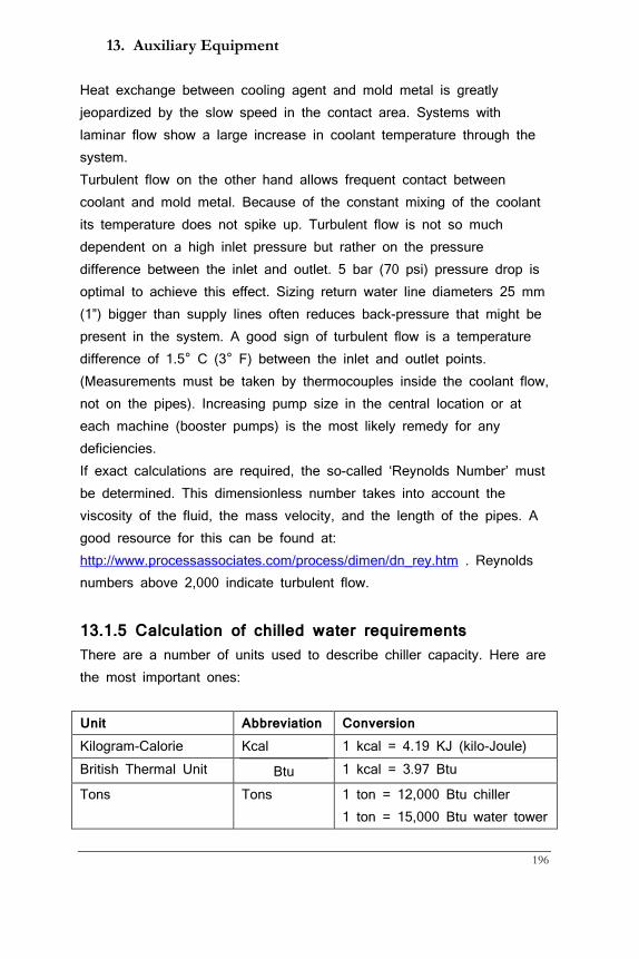
13. Auxiliary Equipment
196
Heat exchange between cooling agent and mold metal is greatly jeopardized by the slow speed in the contact area. Systems with laminar flow show a large increase in coolant temperature through the system. Turbulent flow on the other hand allows frequent contact between coolant and mold metal. Because of the constant mixing of the coolant its temperature does not spike up. Turbulent flow is not so much dependent on a high inlet pressure but rather on the pressure difference between the inlet and outlet. 5 bar (70 psi) pressure drop is optimal to achieve this effect. Sizing return water line diameters 25 mm (1”) bigger than supply lines often reduces back-pressure that might be present in the system. A good sign of turbulent flow is a temperature difference of 1.5° C (3° F) between the inlet and outlet points. (Measurements must be taken by thermocouples inside the coolant flow, not on the pipes). Increasing pump size in the central location or at each machine (booster pumps) is the most likely remedy for any deficiencies. If exact calculations are required, the so-called ‘Reynolds Number’ must be determined. This dimensionless number takes into account the viscosity of the fluid, the mass velocity, and the length of the pipes. A good resource for this can be found at: http://www.processassociates.com/process/dimen/dn_rey.htm . Reynolds numbers above 2,000 indicate turbulent flow.
13.1.5 Calculation of chilled water requirements There are a number of units used to describe chiller capacity. Here are the most important ones: Unit Abbreviation Conversion Kilogram-Calorie Kcal 1 kcal = 4.19 KJ (kilo-Joule) British Thermal Unit Btu 1 kcal = 3.97 Btu
Tons Tons 1 ton = 12,000 Btu chiller 1 ton = 15,000 Btu water tower
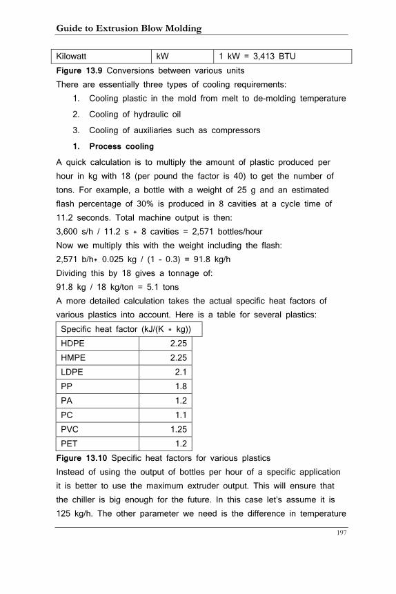
Guide to Extrusion Blow Molding
197
Kilowatt kW 1 kW = 3,413 BTU Figure 13.9 Conversions between various units There are essentially three types of cooling requirements:
1. Cooling plastic in the mold from melt to de-molding temperature
2. Cooling of hydraulic oil
3. Cooling of auxiliaries such as compressors
1. Process cooling
A quick calculation is to multiply the amount of plastic produced per hour in kg with 18 (per pound the factor is 40) to get the number of tons. For example, a bottle with a weight of 25 g and an estimated flash percentage of 30% is produced in 8 cavities at a cycle time of 11.2 seconds. Total machine output is then: 3,600 s/h / 11.2 s * 8 cavities = 2,571 bottles/hour Now we multiply this with the weight including the flash: 2,571 b/h* 0.025 kg / (1 – 0.3) = 91.8 kg/h Dividing this by 18 gives a tonnage of: 91.8 kg / 18 kg/ton = 5.1 tons A more detailed calculation takes the actual specific heat factors of various plastics into account. Here is a table for several plastics: Specific heat factor (kJ/(K * kg)) HDPE 2.25
HMPE 2.25 LDPE 2.1 PP 1.8 PA 1.2 PC 1.1 PVC 1.25 PET 1.2 Figure 13.10 Specific heat factors for various plastics
Instead of using the output of bottles per hour of a specific application it is better to use the maximum extruder output. This will ensure that the chiller is big enough for the future. In this case let’s assume it is 125 kg/h. The other parameter we need is the difference in temperature
13. Auxiliary Equipment
198
(the delta T) between the melt and the de-molding temperature. We assume here a medium melt temperature for HDPE of 200°C and a de-molding temperature of 60° C. This makes the delta T 140° C. The formula is: Output X specific heat X delta T and in our case 125 kg/h * 2.25 kJ/(C * kg) * 140°C = 39,375 kJ/h or 44,731 BTU/h Since this is chilled water we need to divide the BTU value by 12,000 to get tons: 44.731 BTU/h / 12,000 BTU/ton = 3.73 tons Adding a 20% safety factor this comes to: 3.73 tons X 1.2 = 4.5 tons This indicates the amount of cooling the chiller must provide. If the chiller also cools the hydraulics the following calculation would add to its tonnage.
2. Hydraulic oil cooling
If the blow molding machine uses hydraulic pumps oil heats up during machine operation and must be cooled to a temperature not exceeding 55° C (131° F). This can be accomplished by either chilled or tower water. Horsepower in this calculation refers to the hp of the pump motor on the blow molding machine. If chilled water is used the calculation is: Tonnage = hp * DC * 2,684 kJ (2,547 Btu) / 12,648 kJ (12,000Btu) where DC is duty cycle of the pump If tower water is used the formula is: Tonnage = hp * DC * 2,684 kJ (2,547 Btu) / 15,810 kJ (15,000Btu)
3. Cooling of auxiliaries
Other cooling requirements come from machines such as compressors and material dryers if applicable. All equipment specifications identify the amount of water flow needed and the difference between water inlet and outlet temperatures. To convert this information into chiller tonnage use the formula:
Guide to Extrusion Blow Molding
199
Tonnage = Flow in m3/hour * DT in °C x 4,078 / 12,000 or 15,000 Btu Tonnage = Flow in gpm * DT in °F x 500 / 12,000 or 15,000 Btu
4. Pump sizing
These approximations can be used to calculate the proper size of pump for your system: Chiller: 30 l/min (8 gpm) for each ton of chilling capacity Water tower: 13.2 l/min (3 gpm) for each ton of chilling capacity Using the flow rate obtained in this way the nominal brake horsepower can be calculated, entering 6 to 7 bar (87 to 101 psi) as delivery pressure. This value must then be correlated to actual pump curves resulting in a somewhat higher pump horsepower actually required. Both chiller and water tower should have stand-by pumps. These may be alternately used on a weekly basis and act as backup should one them go down. It is a relatively inexpensive investment and will avoid production stops due to pump failure. Most chillers are rated on the basis of 10° C (50 F) water supply temperature. For every 0.6° C (1 F) drop in temperature from this figure the chiller loses about 2% of its capacity. Running water below this threshold is usually not required in EBM.
13.2 Compressor Compressors used are piston, and more popular now screw-type machines that typically compress the air to 8 to 10 bar (120 to 150 psi). The compressed air then travels through an after-cooler and de-humidifier and is usually stored in a receiver tank. Unless the installation is in a very dry climate there will always be some residual moisture that has to be dealt with in several ways:
• The receiver tank has a bottom drain
• The pipes run in a slight angle, about 2.5 cm per 3 m (1” per
10 feet)
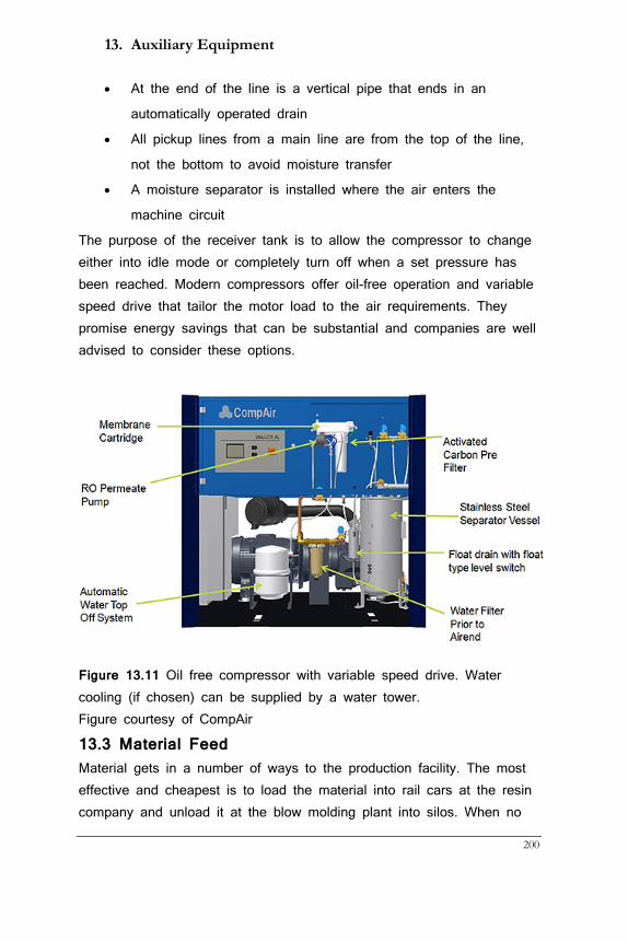
13. Auxiliary Equipment
200
• At the end of the line is a vertical pipe that ends in an
automatically operated drain
• All pickup lines from a main line are from the top of the line,
not the bottom to avoid moisture transfer
• A moisture separator is installed where the air enters the
machine circuit
The purpose of the receiver tank is to allow the compressor to change either into idle mode or completely turn off when a set pressure has been reached. Modern compressors offer oil-free operation and variable speed drive that tailor the motor load to the air requirements. They promise energy savings that can be substantial and companies are well advised to consider these options.
Figure 13.11 Oil free compressor with variable speed drive. Water cooling (if chosen) can be supplied by a water tower. Figure courtesy of CompAir
13.3 Material Feed Material gets in a number of ways to the production facility. The most effective and cheapest is to load the material into rail cars at the resin company and unload it at the blow molding plant into silos. When no
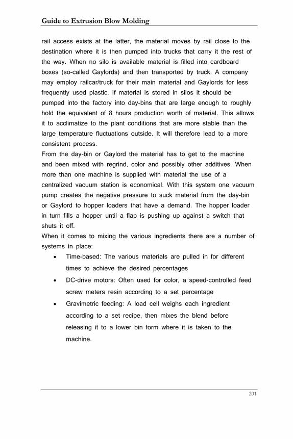
Guide to Extrusion Blow Molding
201
rail access exists at the latter, the material moves by rail close to the destination where it is then pumped into trucks that carry it the rest of the way. When no silo is available material is filled into cardboard boxes (so-called Gaylords) and then transported by truck. A company may employ railcar/truck for their main material and Gaylords for less frequently used plastic. If material is stored in silos it should be pumped into the factory into day-bins that are large enough to roughly hold the equivalent of 8 hours production worth of material. This allows it to acclimatize to the plant conditions that are more stable than the large temperature fluctuations outside. It will therefore lead to a more consistent process. From the day-bin or Gaylord the material has to get to the machine and been mixed with regrind, color and possibly other additives. When more than one machine is supplied with material the use of a centralized vacuum station is economical. With this system one vacuum pump creates the negative pressure to suck material from the day-bin or Gaylord to hopper loaders that have a demand. The hopper loader in turn fills a hopper until a flap is pushing up against a switch that shuts it off. When it comes to mixing the various ingredients there are a number of systems in place:
• Time-based: The various materials are pulled in for different
times to achieve the desired percentages
• DC-drive motors: Often used for color, a speed-controlled feed
screw meters resin according to a set percentage
• Gravimetric feeding: A load cell weighs each ingredient
according to a set recipe, then mixes the blend before
releasing it to a lower bin form where it is taken to the
machine.
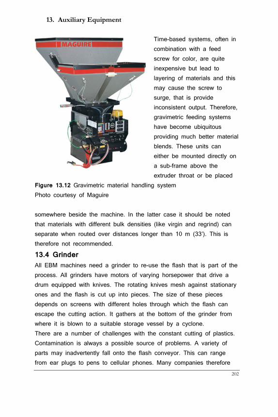
13. Auxiliary Equipment
202
Time-based systems, often in combination with a feed screw for color, are quite inexpensive but lead to layering of materials and this may cause the screw to surge, that is provide inconsistent output. Therefore, gravimetric feeding systems have become ubiquitous providing much better material blends. These units can either be mounted directly on a sub-frame above the extruder throat or be placed
Figure 13.12 Gravimetric material handling system Photo courtesy of Maguire somewhere beside the machine. In the latter case it should be noted that materials with different bulk densities (like virgin and regrind) can separate when routed over distances longer than 10 m (33’). This is therefore not recommended.
13.4 Grinder All EBM machines need a grinder to re-use the flash that is part of the process. All grinders have motors of varying horsepower that drive a drum equipped with knives. The rotating knives mesh against stationary ones and the flash is cut up into pieces. The size of these pieces depends on screens with different holes through which the flash can escape the cutting action. It gathers at the bottom of the grinder from where it is blown to a suitable storage vessel by a cyclone. There are a number of challenges with the constant cutting of plastics. Contamination is always a possible source of problems. A variety of parts may inadvertently fall onto the flash conveyor. This can range from ear plugs to pens to cellular phones. Many companies therefore
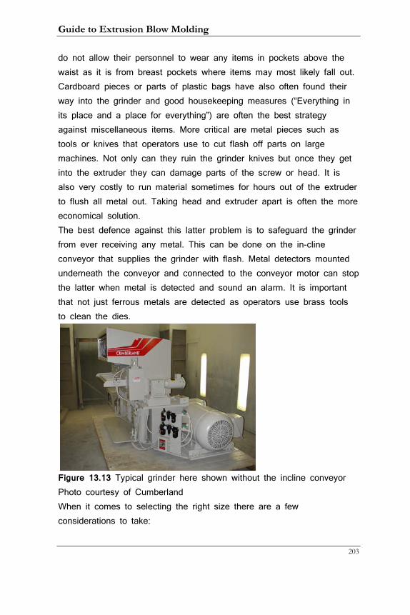
Guide to Extrusion Blow Molding
203
do not allow their personnel to wear any items in pockets above the waist as it is from breast pockets where items may most likely fall out. Cardboard pieces or parts of plastic bags have also often found their way into the grinder and good housekeeping measures (“Everything in its place and a place for everything”) are often the best strategy against miscellaneous items. More critical are metal pieces such as tools or knives that operators use to cut flash off parts on large machines. Not only can they ruin the grinder knives but once they get into the extruder they can damage parts of the screw or head. It is also very costly to run material sometimes for hours out of the extruder to flush all metal out. Taking head and extruder apart is often the more economical solution. The best defence against this latter problem is to safeguard the grinder from ever receiving any metal. This can be done on the in-cline conveyor that supplies the grinder with flash. Metal detectors mounted underneath the conveyor and connected to the conveyor motor can stop the latter when metal is detected and sound an alarm. It is important that not just ferrous metals are detected as operators use brass tools to clean the dies.
Figure 13.13 Typical grinder here shown without the incline conveyor Photo courtesy of Cumberland When it comes to selecting the right size there are a few considerations to take:
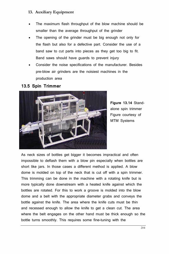
13. Auxiliary Equipment
204
• The maximum flash throughput of the blow machine should be
smaller than the average throughput of the grinder
• The opening of the grinder must be big enough not only for
the flash but also for a defective part. Consider the use of a
band saw to cut parts into pieces as they get too big to fit.
Band saws should have guards to prevent injury
• Consider the noise specifications of the manufacturer. Besides
pre-blow air grinders are the noisiest machines in the
production area
13.5 Spin Trimmer
Figure 13.14 Stand-alone spin trimmer Figure courtesy of MTM Systems
As neck sizes of bottles get bigger it becomes impractical and often impossible to deflash them with a blow pin especially when bottles are short like jars. In those cases a different method is applied. A blow dome is molded on top of the neck that is cut off with a spin trimmer. This trimming can be done in the machine with a rotating knife but is more typically done downstream with a heated knife against which the bottles are rotated. For this to work a groove is molded into the blow dome and a belt with the appropriate diameter grabs and conveys the bottle against the knife. The area where the knife cuts must be thin and recessed enough to allow the knife to get a clean cut. The area where the belt engages on the other hand must be thick enough so the bottle turns smoothly. This requires some fine-tuning with the
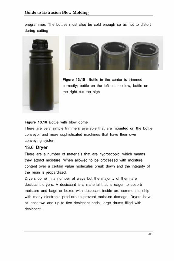
Guide to Extrusion Blow Molding
205
programmer. The bottles must also be cold enough so as not to distort during cutting
Figure 13.15 Bottle in the center is trimmed correctly; bottle on the left cut too low, bottle on the right cut too high
Figure 13.16 Bottle with blow dome There are very simple trimmers available that are mounted on the bottle conveyor and more sophisticated machines that have their own conveying system.
13.6 Dryer There are a number of materials that are hygroscopic, which means they attract moisture. When allowed to be processed with moisture content over a certain value molecules break down and the integrity of the resin is jeopardized. Dryers come in a number of ways but the majority of them are desiccant dryers. A desiccant is a material that is eager to absorb moisture and bags or boxes with desiccant inside are common to ship with many electronic products to prevent moisture damage. Dryers have at least two and up to five desiccant beds, large drums filled with desiccant.
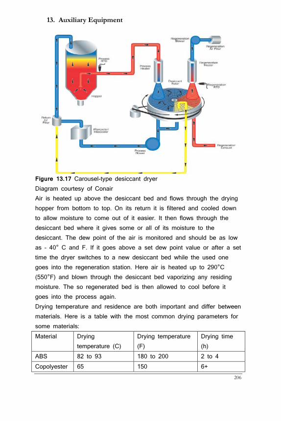
13. Auxiliary Equipment
206
Figure 13.17 Carousel-type desiccant dryer Diagram courtesy of Conair Air is heated up above the desiccant bed and flows through the drying hopper from bottom to top. On its return it is filtered and cooled down to allow moisture to come out of it easier. It then flows through the desiccant bed where it gives some or all of its moisture to the desiccant. The dew point of the air is monitored and should be as low as – 40° C and F. If it goes above a set dew point value or after a set time the dryer switches to a new desiccant bed while the used one goes into the regeneration station. Here air is heated up to 290°C (550°F) and blown through the desiccant bed vaporizing any residing moisture. The so regenerated bed is then allowed to cool before it goes into the process again. Drying temperature and residence are both important and differ between materials. Here is a table with the most common drying parameters for some materials: Material Drying
temperature (C) Drying temperature (F)
Drying time (h)
ABS 82 to 93 180 to 200 2 to 4 Copolyester 65 150 6+
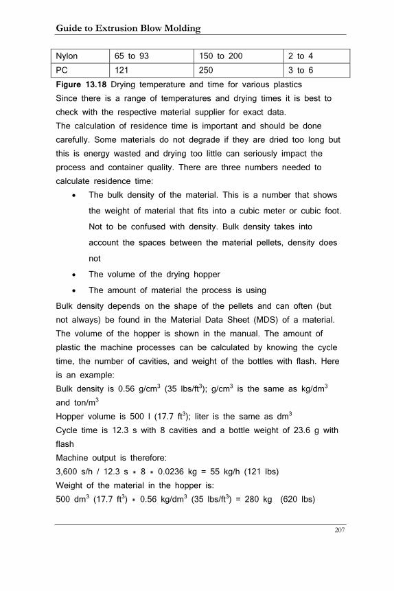
Guide to Extrusion Blow Molding
207
Nylon 65 to 93 150 to 200 2 to 4 PC 121 250 3 to 6 Figure 13.18 Drying temperature and time for various plastics Since there is a range of temperatures and drying times it is best to check with the respective material supplier for exact data. The calculation of residence time is important and should be done carefully. Some materials do not degrade if they are dried too long but this is energy wasted and drying too little can seriously impact the process and container quality. There are three numbers needed to calculate residence time:
• The bulk density of the material. This is a number that shows
the weight of material that fits into a cubic meter or cubic foot.
Not to be confused with density. Bulk density takes into
account the spaces between the material pellets, density does
not
• The volume of the drying hopper
• The amount of material the process is using
Bulk density depends on the shape of the pellets and can often (but not always) be found in the Material Data Sheet (MDS) of a material. The volume of the hopper is shown in the manual. The amount of plastic the machine processes can be calculated by knowing the cycle time, the number of cavities, and weight of the bottles with flash. Here is an example: Bulk density is 0.56 g/cm3 (35 lbs/ft3); g/cm3 is the same as kg/dm3 and ton/m3 Hopper volume is 500 l (17.7 ft3); liter is the same as dm3 Cycle time is 12.3 s with 8 cavities and a bottle weight of 23.6 g with flash Machine output is therefore: 3,600 s/h / 12.3 s * 8 * 0.0236 kg = 55 kg/h (121 lbs) Weight of the material in the hopper is: 500 dm3 (17.7 ft3) * 0.56 kg/dm3 (35 lbs/ft3) = 280 kg (620 lbs)
13. Auxiliary Equipment
208
Guide to Extrusion Blow Molding
209
Residence time is then: 280 kg / 55 kg/h = 5.1 hours This would be enough for Nylon but not enough for co-polyester. If drying should only be 2 hours with this configuration the dryer should not fill to the top but should contain only 110 kg. Modern dryers allow the operator to set the fill level on the hopper for this reason and it is strongly recommended to look for this feature when purchasing a new one!
13.7 Surface Treatment
Practically all produced bottles will either be printed are labeled before they reach the consumer. That is a challenge because plastic molecules are non-polar, which means they do not offer connection sites to other materials like metals or ceramics do. Their surface is essentially inert. That makes it difficult for ink or glue to adhere to these surfaces. Missing print or peeling labels is not just an aesthetic issue but can also have legal liabilities when the information on the bottle contains warnings like it does for medications. This inertness of the plastic surface relates to surface tension. If it is lower than the surface tension of the ink or glue adherence will be problematic. Surface tension is measured in dynes/cm. For good adherence the dynes value of the plastic surface should be 2 to 10 higher than the liquid’s surface tension. Typical plastic surfaces have surface tension of about 30 Dynes and this must be boosted to above 38 to avoid delamination of ink or glue. In order to prepare plastic surfaces for printing and labeling three methods are common:
• Open flame treatment
• Corona treatment
• Cold gas plasma treatment
13.7.1 Flamers Flamers come in three varieties:
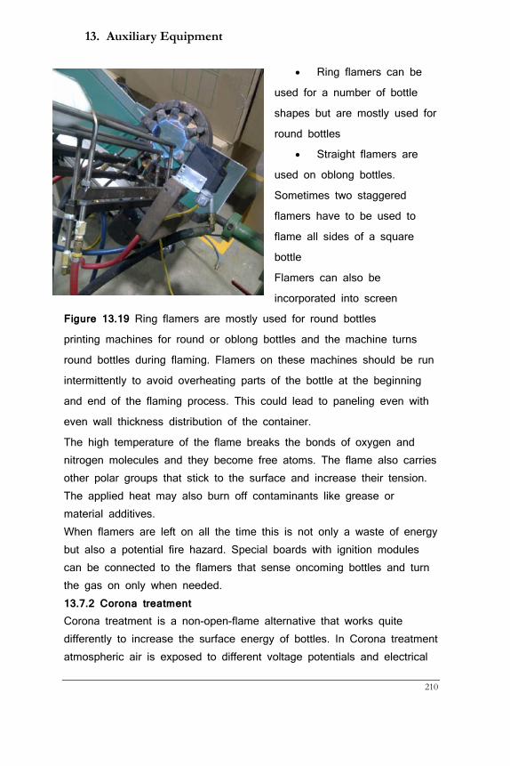
13. Auxiliary Equipment
210
• Ring flamers can be
used for a number of bottle
shapes but are mostly used for
round bottles
• Straight flamers are
used on oblong bottles.
Sometimes two staggered
flamers have to be used to
flame all sides of a square
bottle
• Flamers can also be
incorporated into screen
Figure 13.19 Ring flamers are mostly used for round bottles
printing machines for round or oblong bottles and the machine turns
round bottles during flaming. Flamers on these machines should be run
intermittently to avoid overheating parts of the bottle at the beginning
and end of the flaming process. This could lead to paneling even with
even wall thickness distribution of the container.
The high temperature of the flame breaks the bonds of oxygen and nitrogen molecules and they become free atoms. The flame also carries other polar groups that stick to the surface and increase their tension. The applied heat may also burn off contaminants like grease or material additives. When flamers are left on all the time this is not only a waste of energy but also a potential fire hazard. Special boards with ignition modules can be connected to the flamers that sense oncoming bottles and turn the gas on only when needed. 13.7.2 Corona treatment Corona treatment is a non-open-flame alternative that works quite differently to increase the surface energy of bottles. In Corona treatment atmospheric air is exposed to different voltage potentials and electrical
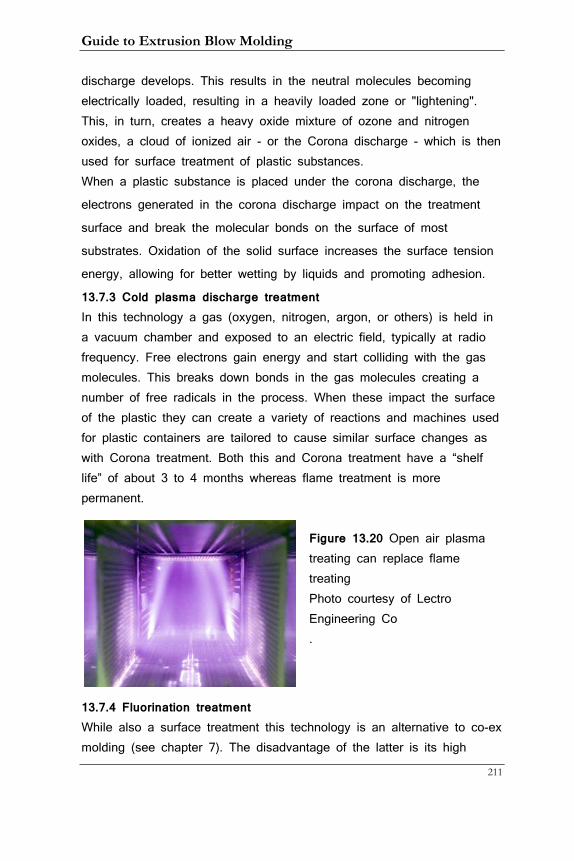
Guide to Extrusion Blow Molding
211
discharge develops. This results in the neutral molecules becoming electrically loaded, resulting in a heavily loaded zone or "lightening". This, in turn, creates a heavy oxide mixture of ozone and nitrogen oxides, a cloud of ionized air - or the Corona discharge - which is then used for surface treatment of plastic substances. When a plastic substance is placed under the corona discharge, the
electrons generated in the corona discharge impact on the treatment
surface and break the molecular bonds on the surface of most
substrates. Oxidation of the solid surface increases the surface tension
energy, allowing for better wetting by liquids and promoting adhesion.
13.7.3 Cold plasma discharge treatment In this technology a gas (oxygen, nitrogen, argon, or others) is held in a vacuum chamber and exposed to an electric field, typically at radio frequency. Free electrons gain energy and start colliding with the gas molecules. This breaks down bonds in the gas molecules creating a number of free radicals in the process. When these impact the surface of the plastic they can create a variety of reactions and machines used for plastic containers are tailored to cause similar surface changes as with Corona treatment. Both this and Corona treatment have a “shelf life” of about 3 to 4 months whereas flame treatment is more permanent.
Figure 13.20 Open air plasma treating can replace flame treating Photo courtesy of Lectro Engineering Co .
13.7.4 Fluorination treatment While also a surface treatment this technology is an alternative to co-ex molding (see chapter 7). The disadvantage of the latter is its high
13. Auxiliary Equipment
212
capital cost and a certain complexity in operation. Fluorination is usually left to specialist companies that charge per container so costs are only dependent on output. There are however a few companies that fluorinate inside the blow molding machine. Fluorine gas is the most reactive of all gases and leads to similar effects on plastic surfaces as we have already seen. In addition it provides a hydrocarbon barrier that depends on exposure time. Containers are assembled into groups and placed for a certain amount of time into a reaction chamber where they are exposed to a mixture of fluorine and nitrogen gas. Barrier performance increase can be dialed in with residence time. Volatile chemicals such as can be found in many lawn and garden products are prevented from escaping from the container thus treated. When fluorination is affected inside the blow machine fluorine gas is pushed into the container for a short period. Because the plastic is still molten at the time residence time is not the same issue as with batch processing of cold containers. Fluorine gas is very dangerous to human health and fluorine meters are placed in the vicinity of the machine to alert personnel to any leaks.
13.9 Packaging Systems Many plants still operate with packers that put bottles manually into boxes. There is a lot to be said for this as observant packers are the first line of defense against container defects but this method is cost-intensive. In a 24/7 environment each position requires 4 people that can get sick, be inattentive, or make mistakes. As machines with higher cavitations and faster cycles are increasingly used more than one packer may be needed behind each machine. Bottle packaging systems promise enhanced reliability and lower operational costs. Here is an overview of what is available:
• For blow and drop machines there are systems that keep the
orientation of the bottles and deflash them
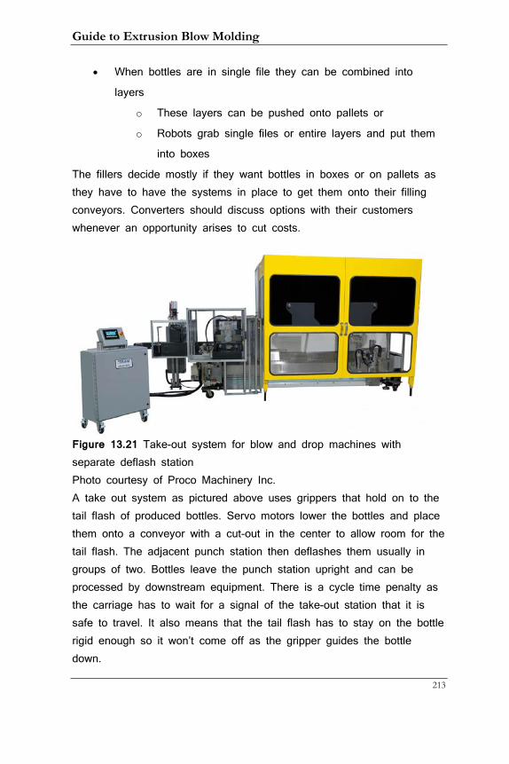
Guide to Extrusion Blow Molding
213
• When bottles are in single file they can be combined into
layers
o These layers can be pushed onto pallets or
o Robots grab single files or entire layers and put them
into boxes
The fillers decide mostly if they want bottles in boxes or on pallets as they have to have the systems in place to get them onto their filling conveyors. Converters should discuss options with their customers whenever an opportunity arises to cut costs.
Figure 13.21 Take-out system for blow and drop machines with separate deflash station Photo courtesy of Proco Machinery Inc. A take out system as pictured above uses grippers that hold on to the tail flash of produced bottles. Servo motors lower the bottles and place them onto a conveyor with a cut-out in the center to allow room for the tail flash. The adjacent punch station then deflashes them usually in groups of two. Bottles leave the punch station upright and can be processed by downstream equipment. There is a cycle time penalty as the carriage has to wait for a signal of the take-out station that it is safe to travel. It also means that the tail flash has to stay on the bottle rigid enough so it won’t come off as the gripper guides the bottle down.

13. Auxiliary Equipment
214
Tie-bar less shuttle systems do not need this type of take-out. Instead, they feature conveyors that merge the two container streams that typically leave the machine on opposite sides into one. Recip machine take-out systems lay the containers flat onto a conveyor and the punch works vertically instead of horizontally.
Figure 13.22 Take-out systems on recip machines lay the containers flat onto a conveyor Photo courtesy of Graham Machinery Group This works very well for oblong containers but sometimes causes problems with round ones as they may twist on the conveyor. Wheel machines may use horizontal or vertical punches depending on machine layout and bottle shape. As most of these machines are in the high-output category they is always some sort of automated system contributing to high initial capital costs. There are two systems that are currently available to putting bottles into boxes: They are either robotic arms that grab hold of a single file of bottles or an entire layer of bottles is grabbed through grippers or vacuum and placed into boxes.

Guide to Extrusion Blow Molding
215
Robots have become popular as their prices have come down while at the same time it has become easier to configure them. Another system pushes bottles into layers and uses large vacuum plates to place the bottles. In either case the complexity of placing boxes into the right locations and keeping them open should not be underestimated. Firstly, the boxes have to be of high quality so they stay rectangular and do not become the shape of a parallelogram. Liners are always placed into them manually and care must be taken to stretch them out fully inside. A flexible plastic rope helps securing them against being pushed into the box. There are a number of different gripper designs and they should be evaluated for long-term use and easy replacement ability as some of them will break at some point.
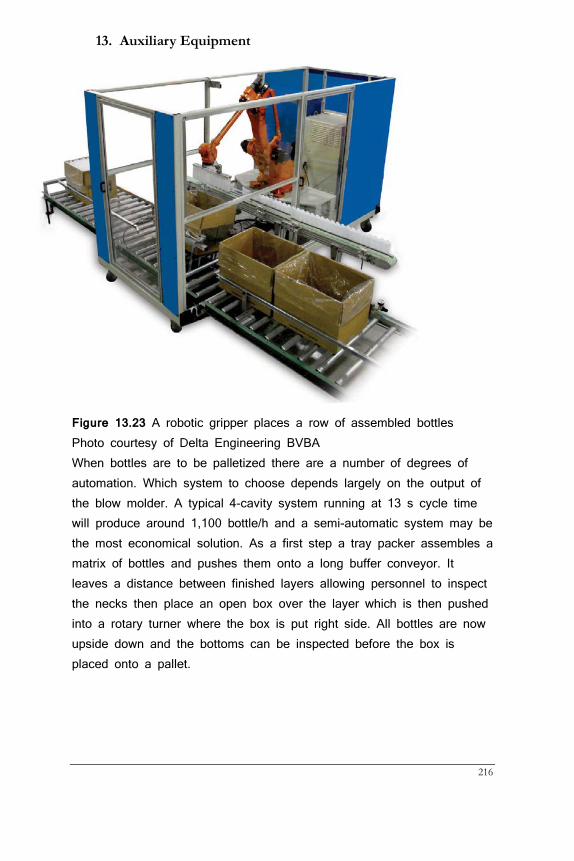
13. Auxiliary Equipment
216
Figure 13.23 A robotic gripper places a row of assembled bottles Photo courtesy of Delta Engineering BVBA When bottles are to be palletized there are a number of degrees of automation. Which system to choose depends largely on the output of the blow molder. A typical 4-cavity system running at 13 s cycle time will produce around 1,100 bottle/h and a semi-automatic system may be the most economical solution. As a first step a tray packer assembles a matrix of bottles and pushes them onto a long buffer conveyor. It leaves a distance between finished layers allowing personnel to inspect the necks then place an open box over the layer which is then pushed into a rotary turner where the box is put right side. All bottles are now upside down and the bottoms can be inspected before the box is placed onto a pallet.
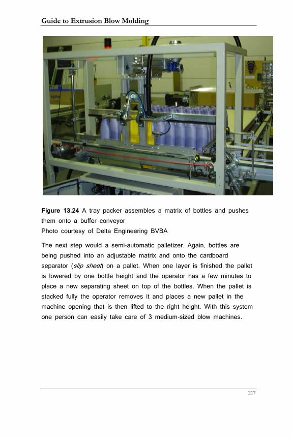
Guide to Extrusion Blow Molding
217
Figure 13.24 A tray packer assembles a matrix of bottles and pushes them onto a buffer conveyor Photo courtesy of Delta Engineering BVBA
The next step would a semi-automatic palletizer. Again, bottles are being pushed into an adjustable matrix and onto the cardboard separator (slip sheet) on a pallet. When one layer is finished the pallet is lowered by one bottle height and the operator has a few minutes to place a new separating sheet on top of the bottles. When the pallet is stacked fully the operator removes it and places a new pallet in the machine opening that is then lifted to the right height. With this system one person can easily take care of 3 medium-sized blow machines.
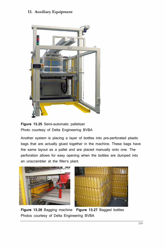
13. Auxiliary Equipment
218
Figure 13.25 Semi-automatic palletizer Photo courtesy of Delta Engineering BVBA
Another system is placing a layer of bottles into pre-perforated plastic bags that are actually glued together in the machine. These bags have the same layout as a pallet and are placed manually onto one. The perforation allows for easy opening when the bottles are dumped into an unscrambler at the filler’s plant.
Figure 13.26 Bagging machine Figure 13.27 Bagged bottles Photos courtesy of Delta Engineering BVBA
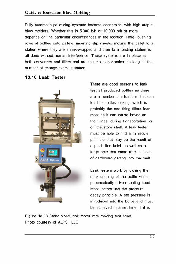
Guide to Extrusion Blow Molding
219
Fully automatic palletizing systems become economical with high output blow molders. Whether this is 5,000 b/h or 10,000 b/h or more depends on the particular circumstances in the location. Here, pushing rows of bottles onto pallets, inserting slip sheets, moving the pallet to a station where they are shrink-wrapped and then to a loading station is all done without human interference. These systems are in place at both converters and fillers and are the most economical as long as the number of change-overs is limited.
13.10 Leak Tester There are good reasons to leak test all produced bottles as there are a number of situations that can lead to bottles leaking, which is probably the one thing fillers fear most as it can cause havoc on their lines, during transportation, or on the store shelf. A leak tester must be able to find a miniscule pin hole that may be the result of a pinch line knick as well as a large hole that came from a piece of cardboard getting into the melt. Leak testers work by closing the neck opening of the bottle via a pneumatically driven sealing head. Most testers use the pressure decay principle. A set pressure is introduced into the bottle and must be achieved in a set time. If it is
Figure 13.28 Stand-alone leak tester with moving test head Photo courtesy of ALPS LLC
13. Auxiliary Equipment
220
not, a large hole is the reason and the container is rejected. If the pressure is reached, the tester logs it. Pressure will now drop by a certain amount and the bottle will be rejected when it drops below a certain limit. This can be done with one or two time limits. The second one would be used to find tiny holes where pressure loss takes a certain time before the machine can detect it. Of course, this will take longer and a compromise between the fastest speed and the smallest detectable hole has to be found when speed is an issue. In many companies bottles with different size holes are made once and then placed beside the leak tester to test its functionality. This popular practice is actually fault-ridden. When containers are measured in-line they are still not cooled completely and behave differently compared to completely cooled containers. This is because sidewalls bulge out more easily when the container is warm and this leads to a different pressure curve during testing. As a result many good bottles are discarded by the leak tester as faulty costing processors thousands of dollars per year. Leak testers should therefore be tested only with bottles that are at the same temperature than the ones that are coming off the line regularly. Leak testers are usually placed at the end of a conveyor before the bottle is packed. To gain speed leak testers may have two or three testing heads in linear systems or up to 30 in rotary machines that can test over 1,000 bottles/minute. Many testers stop containers on the line with extendable pneumatic pistons for the test. Others move the test head with the bottle to get around issues with bottles falling over when the conveyor is stopped or pistons hit bottles. When speed requires more than one test head they are organized to test every second or third bottle as they move along the conveyor. Leak testers can also be incorporated into the blow machine but this requires a higher capital expense as the number of heads needed is dependent on cavitation rather than what each head can process.
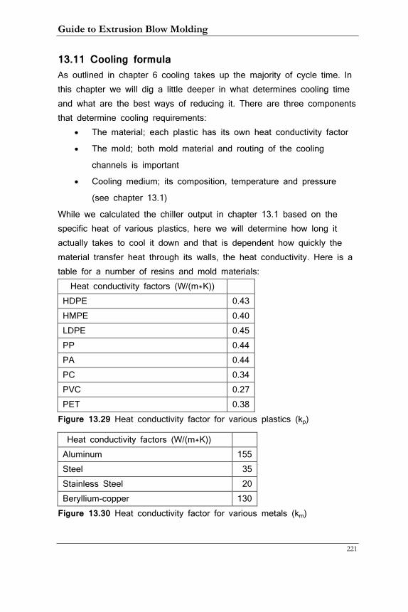
Guide to Extrusion Blow Molding
221
13.11 Cooling formula As outlined in chapter 6 cooling takes up the majority of cycle time. In this chapter we will dig a little deeper in what determines cooling time and what are the best ways of reducing it. There are three components that determine cooling requirements:
• The material; each plastic has its own heat conductivity factor
• The mold; both mold material and routing of the cooling
channels is important
• Cooling medium; its composition, temperature and pressure
(see chapter 13.1)
While we calculated the chiller output in chapter 13.1 based on the specific heat of various plastics, here we will determine how long it actually takes to cool it down and that is dependent how quickly the material transfer heat through its walls, the heat conductivity. Here is a table for a number of resins and mold materials:
Heat conductivity factors (W/(m*K)) HDPE 0.43 HMPE 0.40 LDPE 0.45 PP 0.44 PA 0.44 PC 0.34 PVC 0.27 PET 0.38
Figure 13.29 Heat conductivity factor for various plastics (kp)
Heat conductivity factors (W/(m*K)) Aluminum 155 Steel 35 Stainless Steel 20 Beryllium-copper 130
Figure 13.30 Heat conductivity factor for various metals (km)
13. Auxiliary Equipment
222
The formula for cooling time is thus: CT = (kp/(km/W^2)/(W^2*0.33)*W^2*(MT-DT))/(LOG(W*10)) Where: CT = cycle time W = maximum wall thickness of container MT = melt temperature DT = de-molding temperature (This formula assumes a large pressure drop between water in and out as explained earlier) The most striking feature of this formula is that the wall thickness always appears squared; it is by far the most important factor. This points out that operators should make best use of programmers and/or ovalization techniques to minimize thick spots as this will help reducing cycle time and contribute to the profitability of an operation.
13.12 Monitoring environmental conditions
Most blow molding plants do not have air conditioning and are so subject to changes in temperature and humidity (barometric pressure may also play a role, albeit a smaller one). The main issue is mold sweating which eventually leads to water marks on the containers. Mold sweating is dependent on the dew point. Air can hold a certain amount of moisture depending on its temperature. As air heats up in the summer months it takes on more moisture when it can. The dew point is that temperature where water vapor has to condense out of the air and become liquid again. We call condensed water dew when it settles on a surface like grass, hence the name dew point.
What happens in the factory is that air around the cooled molds and pipes cools down and suddenly can no longer hold the moisture that then condenses on said molds and pipes. What most operators do is to choke water flow to the mold and increase cycle time to make up for the loss of cooling. They do this in response to water marks appearing on the containers. Choking water flow is not optimal; it would be better
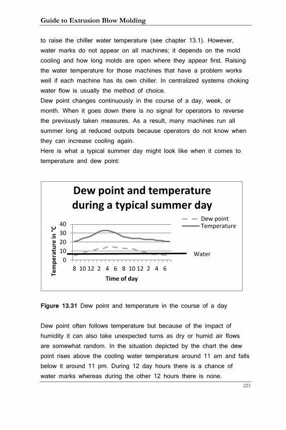
Guide to Extrusion Blow Molding
223
to raise the chiller water temperature (see chapter 13.1). However, water marks do not appear on all machines; it depends on the mold cooling and how long molds are open where they appear first. Raising the water temperature for those machines that have a problem works well if each machine has its own chiller. In centralized systems choking water flow is usually the method of choice. Dew point changes continuously in the course of a day, week, or month. When it goes down there is no signal for operators to reverse the previously taken measures. As a result, many machines run all summer long at reduced outputs because operators do not know when they can increase cooling again. Here is what a typical summer day might look like when it comes to temperature and dew point:
Figure 13.31 Dew point and temperature in the course of a day Dew point often follows temperature but because of the impact of humidity it can also take unexpected turns as dry or humid air flows are somewhat random. In the situation depicted by the chart the dew point rises above the cooling water temperature around 11 am and falls below it around 11 pm. During 12 day hours there is a chance of water marks whereas during the other 12 hours there is none.
0 10 20 30 40
8 10 12 2 4 6 8 10 12 2 4 6
Tem
pera
ture
in °C
Time of day
Dew point and temperature during a typical summer day
Dew point Temperature
Water
13. Auxiliary Equipment
224
This situation causes two distinctly possible and equally unappealing scenarios:
• When the dew point rises above the cooling water temperature
it may cause water marks that can go undetected for some
time, possibly causing scrap and/or sorting
• When the dew point sinks below, the machines may run slower
than they need to causing a loss of profitability
It is therefore recommended to monitor the dew point in the plant and take appropriate measures. This can be done in a variety of ways. The lowest investment would be a handheld dew point meter. More sophisticated sensors can transmit data to a computer or tablet that can be viewed anywhere with a browser. A better solution would be to have an application on a computer in the plant that alarms the operators to the prevailing condition and gives concrete advice on what to do.
Guide to Extrusion Blow Molding
225
14. Process Troubleshooting Guidelines
Before going into the particular defects in the next chapter a few words on the methodology.
Here are some rules I have found helpful in tackling problems. The first is attitude. Every problem has a solution and the attitude should reflect this knowledge. There is no point in getting mad or to panic, both emotions actually stifle thinking. Logical thinking, observation of cause and consequence, imagination, and the courage of trying out something new are the characteristics of a good trouble-shooter. Asking a co-worker for help is no sign of weakness, remember: mastery of any field requires being a student for life and this is certainly true for the EBM process.
During mold installation setup people should try to achieve a large process window; that is a set of conditions that yields acceptable bottles. There are at least two points to this:
• Producing bottles in the center of the specification
• Having all cavities produce acceptable bottles with every shot
The fist point is important because operating conditions may change due to changes in the plant environment, re-grind percentage, or material differences. If all neck dimensions are on the low side already it does not take much to bring them below specifications for example. The second point is a typical EBM issue: when the process is running at the edge of the window, most bottles will be okay with some cycles producing scrap bottles on some cavities. This could be caused by machine malfunctioning – for example slight changes in blow pin speeds – or minute changes in melt temperature and with it swell. A typical example would be so-called neck ears (see chapter 15.20) appearing every so often. Or it could be a knife cut that is less than optimal producing push-ins every once in a while. The cost of running a sub-
14. Troubleshooting Guidelines
226
optimal process can be enormous, from the cost of sorting or re-grinding scrap bottles, or, if faulty bottles go undetected, to the rejection of an entire truck load by the customer, or, in the worst case, a law suit brought on because of containers failing in the field.
The key to broaden the process window is to experiment with critical parameters. What these are depends on the actual application. It could be the mold closing sequence of a large part, the head support air timing, or blow air control. The steps involved are to increase these parameters until failure occurs, then decreasing them to the same point and finding the middle between those two adjustments. If for example the cutting delay timer has to be at 0.18 s and no other delay will work it means that the processor should find other means of being able to get a good cut like changing the bobbing or carriage delay back sequence or the program. The process that can only run with this timer set to 0.18 s will not run consistently in a 24-hour production environment!
If an unforeseen problem does occur during a production run, before troubleshooting can be started there must be agreement on what and how severe the problem is. This is often not as easy as it sounds. There may be disagreement between floor and QC personnel what constitutes a defect. QC personnel should have the last word as it is their responsibility but processors should know what that is.
Next the problem has to be classified. If every container has the same defect, this is easy. But in many cases defects occur intermittently or only on some cavities. Before starting to work on the solution there must be a clear understanding of the scope of the problem:
• How many cavities are affected?
• How often does the defect appear?
• Does it temporarily disappear?
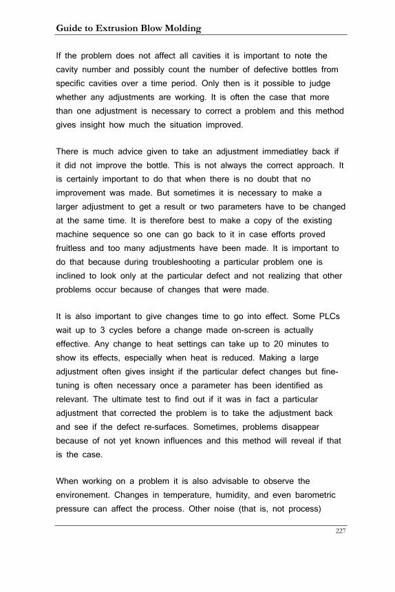
Guide to Extrusion Blow Molding
227
If the problem does not affect all cavities it is important to note the cavity number and possibly count the number of defective bottles from specific cavities over a time period. Only then is it possible to judge whether any adjustments are working. It is often the case that more than one adjustment is necessary to correct a problem and this method gives insight how much the situation improved.
There is much advice given to take an adjustment immediatley back if it did not improve the bottle. This is not always the correct approach. It is certainly important to do that when there is no doubt that no improvement was made. But sometimes it is necessary to make a larger adjustment to get a result or two parameters have to be changed at the same time. It is therefore best to make a copy of the existing machine sequence so one can go back to it in case efforts proved fruitless and too many adjustments have been made. It is important to do that because during troubleshooting a particular problem one is inclined to look only at the particular defect and not realizing that other problems occur because of changes that were made.
It is also important to give changes time to go into effect. Some PLCs wait up to 3 cycles before a change made on-screen is actually effective. Any change to heat settings can take up to 20 minutes to show its effects, especially when heat is reduced. Making a large adjustment often gives insight if the particular defect changes but fine-tuning is often necessary once a parameter has been identified as relevant. The ultimate test to find out if it was in fact a particular adjustment that corrected the problem is to take the adjustment back and see if the defect re-surfaces. Sometimes, problems disappear because of not yet known influences and this method will reveal if that is the case.
When working on a problem it is also advisable to observe the environement. Changes in temperature, humidity, and even barometric pressure can affect the process. Other noise (that is, not process)

14. Troubleshooting Guidelines
228
factors are a new batch of material, a recent repair made to the machine, or an unfamiliar sound.
More than any other quality of a good troubleshooter is the ability to see cause-consequence relationships and not to be intimidated by the machinery. A deep understanding of the process in all its facets is paramount to have the courage to make changes and observe the outcome.
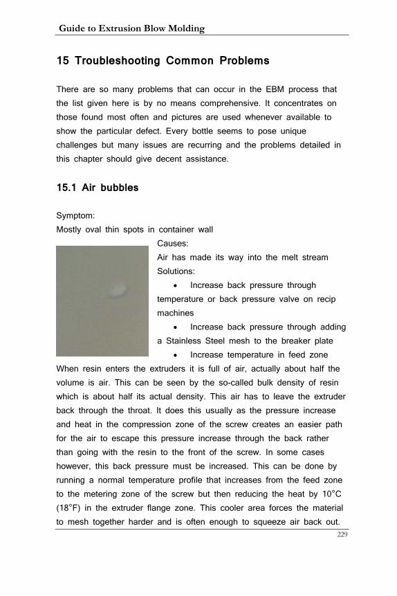
Guide to Extrusion Blow Molding
229
15 Troubleshooting Common Problems
There are so many problems that can occur in the EBM process that the list given here is by no means comprehensive. It concentrates on those found most often and pictures are used whenever available to show the particular defect. Every bottle seems to pose unique challenges but many issues are recurring and the problems detailed in this chapter should give decent assistance.
15.1 Air bubbles
Symptom: Mostly oval thin spots in container wall
Causes: Air has made its way into the melt stream Solutions:
• Increase back pressure through temperature or back pressure valve on recip machines
• Increase back pressure through adding a Stainless Steel mesh to the breaker plate
• Increase temperature in feed zone When resin enters the extruders it is full of air, actually about half the volume is air. This can be seen by the so-called bulk density of resin which is about half its actual density. This air has to leave the extruder back through the throat. It does this usually as the pressure increase and heat in the compression zone of the screw creates an easier path for the air to escape this pressure increase through the back rather than going with the resin to the front of the screw. In some cases however, this back pressure must be increased. This can be done by running a normal temperature profile that increases from the feed zone to the metering zone of the screw but then reducing the heat by 10°C (18°F) in the extruder flange zone. This cooler area forces the material to mesh together harder and is often enough to squeeze air back out.
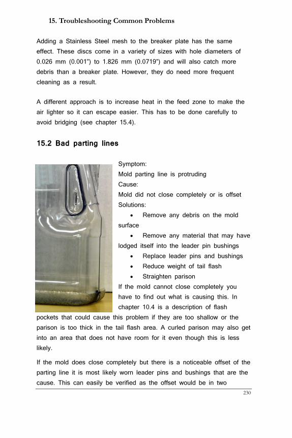
15. Troubleshooting Common Problems
230
Adding a Stainless Steel mesh to the breaker plate has the same effect. These discs come in a variety of sizes with hole diameters of 0.026 mm (0.001”) to 1.826 mm (0.0719”) and will also catch more debris than a breaker plate. However, they do need more frequent cleaning as a result.
A different approach is to increase heat in the feed zone to make the air lighter so it can escape easier. This has to be done carefully to avoid bridging (see chapter 15.4).
15.2 Bad parting lines
Symptom: Mold parting line is protruding Cause: Mold did not close completely or is offset Solutions:
• Remove any debris on the mold surface
• Remove any material that may have lodged itself into the leader pin bushings
• Replace leader pins and bushings • Reduce weight of tail flash • Straighten parison
If the mold cannot close completely you have to find out what is causing this. In chapter 10.4 is a description of flash
pockets that could cause this problem if they are too shallow or the parison is too thick in the tail flash area. A curled parison may also get into an area that does not have room for it even though this is less likely.
If the mold does close completely but there is a noticeable offset of the parting line it is most likely worn leader pins and bushings that are the cause. This can easily be verified as the offset would be in two
Guide to Extrusion Blow Molding
231
different directions and, if not visible, this can be checked with a fingernail easily.
15.3 Bottom webbing
Symptom: Thick material lines in the container bottom Causes: Parison folded on itself during mold closing Solutions:
• Increase constant
support air
• Reduce closing speed
• Sharpen knife
• Reduce melt
temperature to add strength to
parison
15.4 Condensation marks
Symptom: Splotchy area on the container surface Cause: Air around the mold surface cannot hold the enclosed moisture and it condensates on the mold Solutions:
• Raise chiller water temperature
• Choke water flow
• Increase blow time accordingly
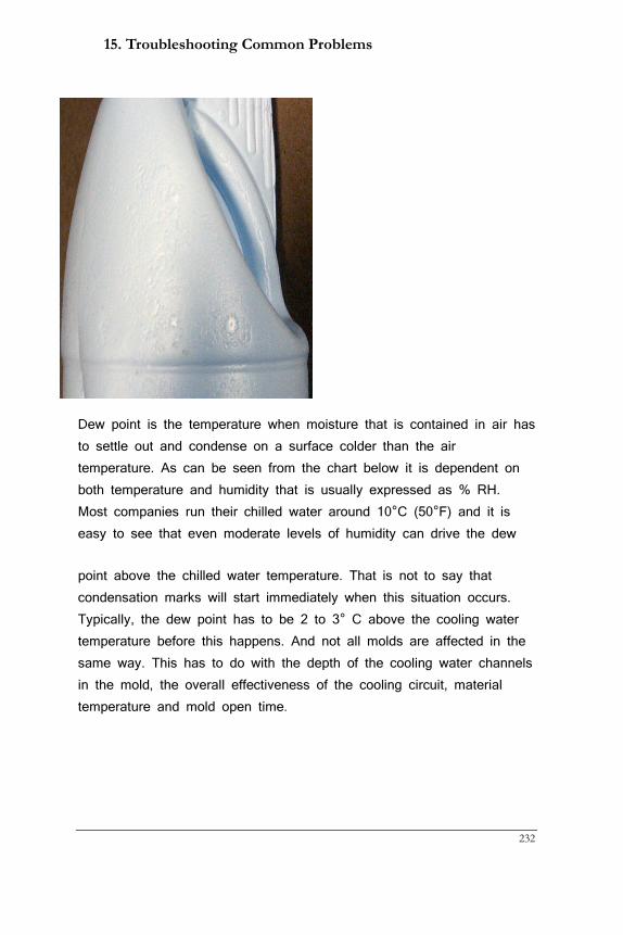
15. Troubleshooting Common Problems
232
Dew point is the temperature when moisture that is contained in air has to settle out and condense on a surface colder than the air temperature. As can be seen from the chart below it is dependent on both temperature and humidity that is usually expressed as % RH. Most companies run their chilled water around 10°C (50°F) and it is easy to see that even moderate levels of humidity can drive the dew
point above the chilled water temperature. That is not to say that condensation marks will start immediately when this situation occurs. Typically, the dew point has to be 2 to 3° C above the cooling water temperature before this happens. And not all molds are affected in the same way. This has to do with the depth of the cooling water channels in the mold, the overall effectiveness of the cooling circuit, material temperature and mold open time.
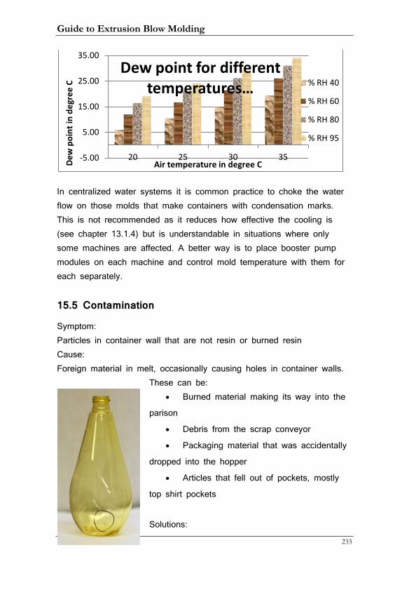
Guide to Extrusion Blow Molding
233
In centralized water systems it is common practice to choke the water flow on those molds that make containers with condensation marks. This is not recommended as it reduces how effective the cooling is (see chapter 13.1.4) but is understandable in situations where only some machines are affected. A better way is to place booster pump modules on each machine and control mold temperature with them for each separately.
15.5 Contamination
Symptom: Particles in container wall that are not resin or burned resin Cause: Foreign material in melt, occasionally causing holes in container walls.
These can be: • Burned material making its way into the
parison
• Debris from the scrap conveyor
• Packaging material that was accidentally
dropped into the hopper
• Articles that fell out of pockets, mostly
top shirt pockets
Solutions:
-5.00
5.00
15.00
25.00
35.00
20 25 30 35
Dew
poi
nt in
deg
ree
C
Air temperature in degree C
Dew point for different temperatures … % RH 40
% RH 60
% RH 80
% RH 95
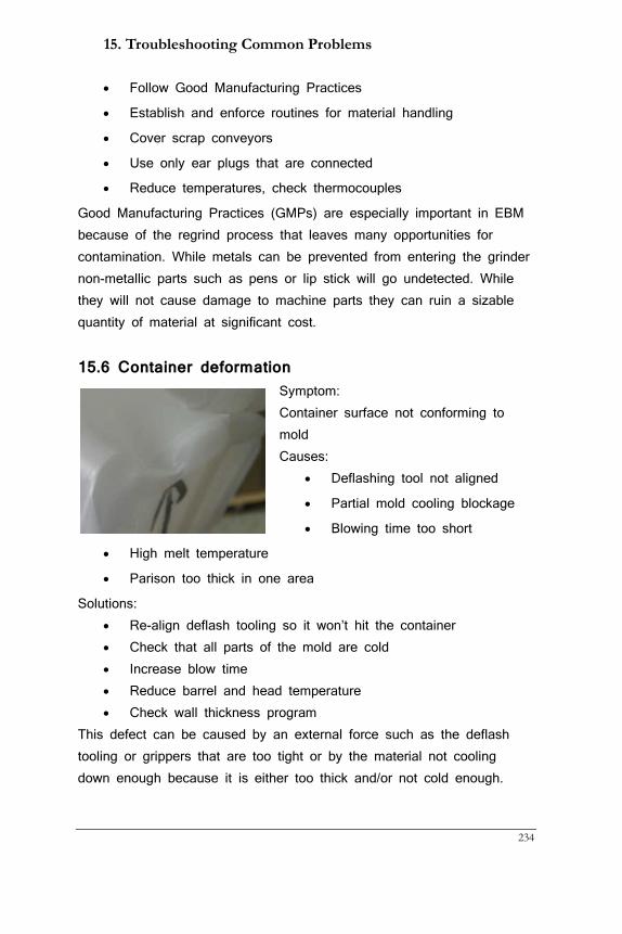
15. Troubleshooting Common Problems
234
• Follow Good Manufacturing Practices
• Establish and enforce routines for material handling
• Cover scrap conveyors
• Use only ear plugs that are connected
• Reduce temperatures, check thermocouples
Good Manufacturing Practices (GMPs) are especially important in EBM because of the regrind process that leaves many opportunities for contamination. While metals can be prevented from entering the grinder non-metallic parts such as pens or lip stick will go undetected. While they will not cause damage to machine parts they can ruin a sizable quantity of material at significant cost.
15.6 Container deformation Symptom: Container surface not conforming to mold Causes:
• Deflashing tool not aligned
• Partial mold cooling blockage
• Blowing time too short
• High melt temperature
• Parison too thick in one area
Solutions: • Re-align deflash tooling so it won’t hit the container • Check that all parts of the mold are cold • Increase blow time • Reduce barrel and head temperature • Check wall thickness program
This defect can be caused by an external force such as the deflash tooling or grippers that are too tight or by the material not cooling down enough because it is either too thick and/or not cold enough.
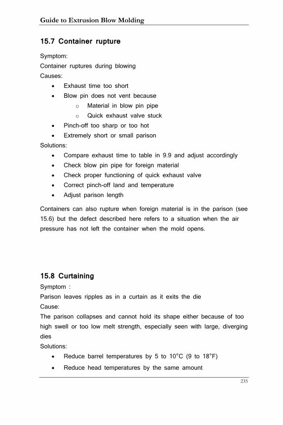
Guide to Extrusion Blow Molding
235
15.7 Container rupture
Symptom: Container ruptures during blowing Causes:
• Exhaust time too short • Blow pin does not vent because
o Material in blow pin pipe o Quick exhaust valve stuck
• Pinch-off too sharp or too hot • Extremely short or small parison
Solutions: • Compare exhaust time to table in 9.9 and adjust accordingly • Check blow pin pipe for foreign material • Check proper functioning of quick exhaust valve • Correct pinch-off land and temperature • Adjust parison length
Containers can also rupture when foreign material is in the parison (see 15.6) but the defect described here refers to a situation when the air pressure has not left the container when the mold opens.
15.8 Curtaining Symptom : Parison leaves ripples as in a curtain as it exits the die Cause: The parison collapses and cannot hold its shape either because of too high swell or too low melt strength, especially seen with large, diverging dies Solutions:
• Reduce barrel temperatures by 5 to 10°C (9 to 18°F)
• Reduce head temperatures by the same amount

15. Troubleshooting Common Problems
236
• Increase die temperature if you suspect high swell to be the
problem
• Check melt flow index of the resin; it may have changed from
a previous run
The reason that material grades for blow molding have much lower MI values (see chapter 4.3) than for example injection molding grades is that they have to have what is called ‘hang strength’, that is the ability of the parison to hold its own weight as it exits the die. This strength means that resin viscosity is high and as we have seen in previous chapters, viscosity is temperature dependent. Since there is a large process window to run most plastics (see chapter 5.3) it is always advisable to try to run them at the lower end of the temperature range. This reduces the risk of curtaining if melt strength is the culprit. If it is too much swell the cure is the opposite as higher melt temperature leads to less swell (see chapter 5.4). When in doubt try raising the die temperature by 15°C (27°F). If that improves the situation swell is the problem.
15.9 Discoloration or uneven color appearance
Symptom: Color saturation is not even on the container surface Causes:
• Color has not mixed completely with base resin because of:
• Uneven color feed
• Screw lacks mixing head
• Screw mixing head is plugged
• Masterbatch not compatible with resin
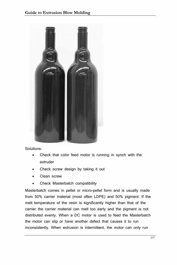
Guide to Extrusion Blow Molding
237
Solutions: • Check that color feed motor is running in synch with the
extruder
• Check screw design by taking it out
• Clean screw
• Check Masterbatch compatibility
Masterbatch comes in pellet or micro-pellet form and is usually made from 50% carrier material (most often LDPE) and 50% pigment. If the melt temperature of the resin is significantly higher than that of the carrier the carrier material can melt too early and the pigment is not distributed evenly. When a DC motor is used to feed the Masterbatch the motor can slip or have another defect that causes it to run inconsistently. When extrusion is intermittent, the motor can only run
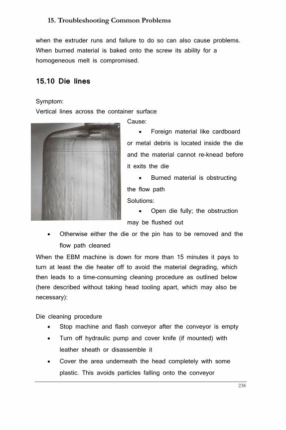
15. Troubleshooting Common Problems
238
when the extruder runs and failure to do so can also cause problems. When burned material is baked onto the screw its ability for a homogeneous melt is compromised.
15.10 Die lines
Symptom: Vertical lines across the container surface
Cause: • Foreign material like cardboard
or metal debris is located inside the die
and the material cannot re-knead before
it exits the die
• Burned material is obstructing
the flow path
Solutions: • Open die fully; the obstruction
may be flushed out
• Otherwise either the die or the pin has to be removed and the
flow path cleaned
When the EBM machine is down for more than 15 minutes it pays to turn at least the die heater off to avoid the material degrading, which then leads to a time-consuming cleaning procedure as outlined below (here described without taking head tooling apart, which may also be necessary):
Die cleaning procedure • Stop machine and flash conveyor after the conveyor is empty
• Turn off hydraulic pump and cover knife (if mounted) with
leather sheath or disassemble it
• Cover the area underneath the head completely with some
plastic. This avoids particles falling onto the conveyor
Guide to Extrusion Blow Molding
239
• Open die fully and leave heats on while cleaning
• Always wear gloves that protect hands and long sleeves to
cover arms
• Use brass tools first to remove as much material from die as
possible
• Later use copper mesh to get smallest particles out. Use soap
alone or together with the copper mesh
• Don’t forget to clean the bottom surface of die and pin
• Take plastic cover out, making sure nothing drops on the
conveyor belt
• Start extruder with die open. Reset after 2 or 3 minutes to
normal opening
• Restart flash conveyor and let it empty into a bag for about 5
minutes to catch any debris that has fallen onto it
15.11 Doughnut formation
Symptom: Parison curls inward or outward when exiting the die Cause: Resin flow rate is slower on the pin or die side and parison curls towards the slower side, often seen at startup and more with large, diverging head tooling Solutions:
• Raise die temperature if parison curls outward
• Reduce die temperature if parison curls inward
• Polish the part towards which the parison curls
• Change pin position relative to die
Flow differences like these are caused by uneven viscosity of the inside and outside of the parison. For example during startup the pin is still colder than the die as the heat has to travel from the die through the
15. Troubleshooting Common Problems
240
die gap to the pin. Higher die temperature means lower viscosity on the outside of the parison that is then exiting faster than the inside and the parison curls inwards. Spraying some mold release spray at the underside of the pin usually helps and is no longer necessary after a short period. After some time in production the problem may reverse itself because the pin heats up through friction and, as the pin is not exposed to cooler air around as the die is, it stays hotter. Since you cannot normally change the pin temperature except when a separate mandrel heater is present you can try to raise the pin position if the parison curls inwards and lower it if it curls outwards. If this problem happens with intermittent extrusion you can do that for the first few program points that produce the tail flash of the part without affecting the wall thickness. If the problem persists one way or the other the side towards which the parison curls may be rougher and polishing it will improve the situation.
15.12 Dull finish
Symptom: Container finish is dull and unattractive Causes:
• Melt temperature too low
• Excessive screw speed
• Too much regrind when running transparent materials such as
PVC
Solutions: • Raise barrel and head temperature and/or die temperature
• Try running with a lower feed zone temperature to increase
output and still lower screw speed
• Use a maximum of 50% regrind with transparent materials
A dull container finish looks unattractive and consumers often buy by looks, especially when they are considering the purchase of a high-priced product like a high-end shampoo, often sold in extrusion blow
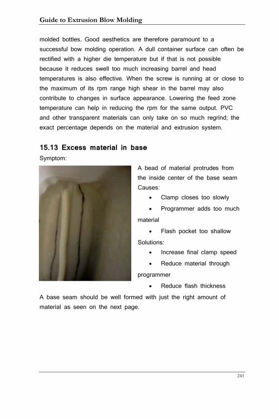
Guide to Extrusion Blow Molding
241
molded bottles. Good aesthetics are therefore paramount to a successful bow molding operation. A dull container surface can often be rectified with a higher die temperature but if that is not possible because it reduces swell too much increasing barrel and head temperatures is also effective. When the screw is running at or close to the maximum of its rpm range high shear in the barrel may also contribute to changes in surface appearance. Lowering the feed zone temperature can help in reducing the rpm for the same output. PVC and other transparent materials can only take on so much regrind; the exact percentage depends on the material and extrusion system.
15.13 Excess material in base Symptom:
A bead of material protrudes from the inside center of the base seam Causes:
• Clamp closes too slowly
• Programmer adds too much
material
• Flash pocket too shallow
Solutions: • Increase final clamp speed
• Reduce material through
programmer
• Reduce flash thickness
A base seam should be well formed with just the right amount of material as seen on the next page.
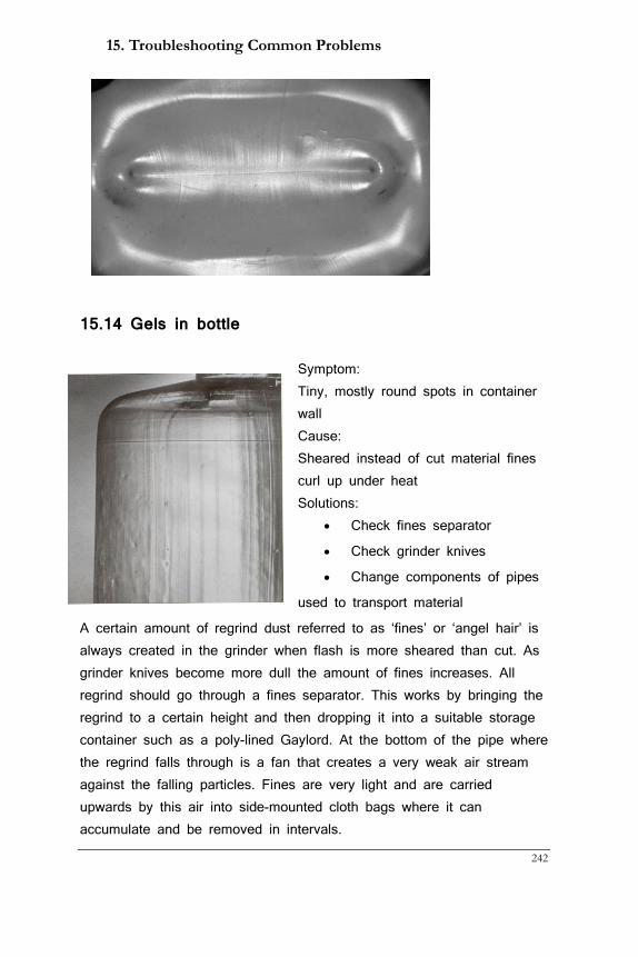
15. Troubleshooting Common Problems
242
15.14 Gels in bottle
Symptom: Tiny, mostly round spots in container wall Cause: Sheared instead of cut material fines curl up under heat Solutions:
• Check fines separator
• Check grinder knives
• Change components of pipes
used to transport material
A certain amount of regrind dust referred to as ‘fines’ or ‘angel hair’ is always created in the grinder when flash is more sheared than cut. As grinder knives become more dull the amount of fines increases. All regrind should go through a fines separator. This works by bringing the regrind to a certain height and then dropping it into a suitable storage container such as a poly-lined Gaylord. At the bottom of the pipe where the regrind falls through is a fan that creates a very weak air stream against the falling particles. Fines are very light and are carried upwards by this air into side-mounted cloth bags where it can accumulate and be removed in intervals.
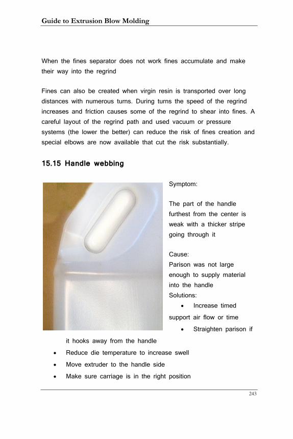
Guide to Extrusion Blow Molding
243
When the fines separator does not work fines accumulate and make their way into the regrind
Fines can also be created when virgin resin is transported over long distances with numerous turns. During turns the speed of the regrind increases and friction causes some of the regrind to shear into fines. A careful layout of the regrind path and used vacuum or pressure systems (the lower the better) can reduce the risk of fines creation and special elbows are now available that cut the risk substantially.
15.15 Handle webbing
Symptom:
The part of the handle furthest from the center is weak with a thicker stripe going through it
Cause: Parison was not large enough to supply material into the handle Solutions:
• Increase timed
support air flow or time
• Straighten parison if
it hooks away from the handle
• Reduce die temperature to increase swell
• Move extruder to the handle side
• Make sure carriage is in the right position
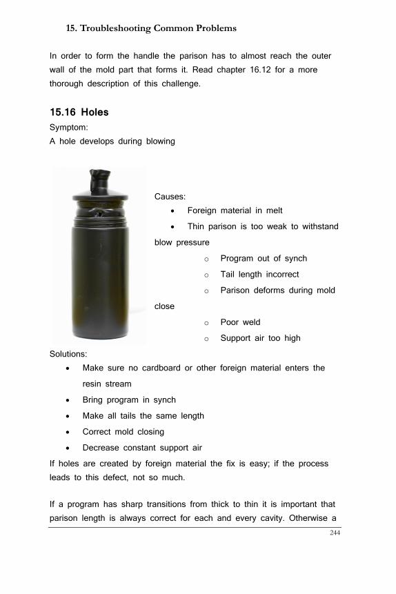
15. Troubleshooting Common Problems
244
In order to form the handle the parison has to almost reach the outer wall of the mold part that forms it. Read chapter 16.12 for a more thorough description of this challenge.
15.16 Holes Symptom: A hole develops during blowing
Causes:
• Foreign material in melt
• Thin parison is too weak to withstand
blow pressure
o Program out of synch
o Tail length incorrect
o Parison deforms during mold
close
o Poor weld
o Support air too high
Solutions: • Make sure no cardboard or other foreign material enters the
resin stream
• Bring program in synch
• Make all tails the same length
• Correct mold closing
• Decrease constant support air
If holes are created by foreign material the fix is easy; if the process leads to this defect, not so much.
If a program has sharp transitions from thick to thin it is important that parison length is always correct for each and every cavity. Otherwise a
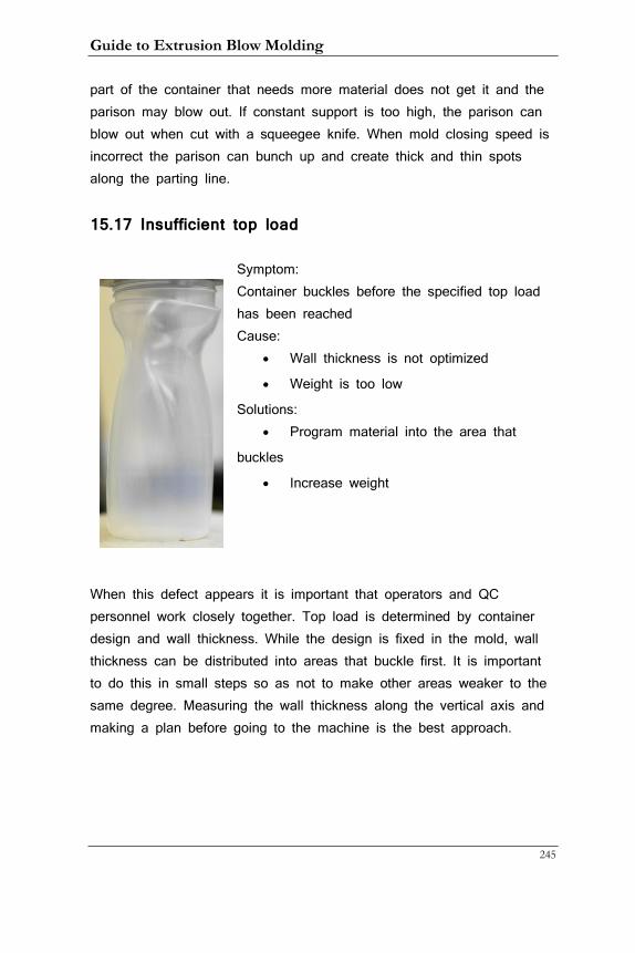
Guide to Extrusion Blow Molding
245
part of the container that needs more material does not get it and the parison may blow out. If constant support is too high, the parison can blow out when cut with a squeegee knife. When mold closing speed is incorrect the parison can bunch up and create thick and thin spots along the parting line.
15.17 Insufficient top load
Symptom: Container buckles before the specified top load has been reached Cause:
• Wall thickness is not optimized
• Weight is too low
Solutions: • Program material into the area that
buckles
• Increase weight
When this defect appears it is important that operators and QC personnel work closely together. Top load is determined by container design and wall thickness. While the design is fixed in the mold, wall thickness can be distributed into areas that buckle first. It is important to do this in small steps so as not to make other areas weaker to the same degree. Measuring the wall thickness along the vertical axis and making a plan before going to the machine is the best approach.
15. Troubleshooting Common Problems
246
15.18 Material degradation Symptom: Brown or black spots in container Cause: Material over-heated or was sheared too much while being extruded Solutions:
• Adjust temperatures to those suitable for the material you are
running
• Reduce temperatures when the machine is down
• Reduce screw speed
While polyolefins are very forgiving when it comes to temperatures other materials are not. PVC is the most sensitive but PETG, nylon and others also require more attention. Follow the instructions of the material suppliers carefully. This may include to always running the extruder empty before shutting the machine down or purging all material out with another material such as LDPE.
15.19 Moisture bubbles Symptom: Small, mostly round bubbles in container Cause: Moisture was able to make its way into the raw material Solutions:
• Eliminate condensation at the extruder throat by increasing
temperature
• Watch for water from leaks that can get to the grinder
• Watch for condensation on overhanging pipes and hoses
• Check dryer for correct temperature and residence time (see
chapter 13.6)
• Check material temperature in feed throat in the winter; if it is
too cold condensation may occur. In that case install a day-bin
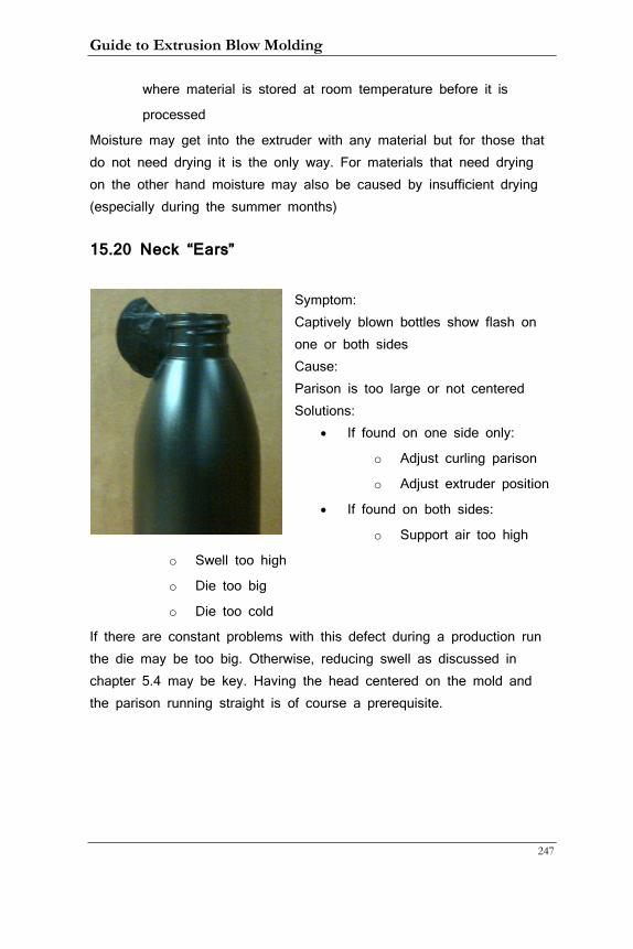
Guide to Extrusion Blow Molding
247
where material is stored at room temperature before it is
processed
Moisture may get into the extruder with any material but for those that do not need drying it is the only way. For materials that need drying on the other hand moisture may also be caused by insufficient drying (especially during the summer months)
15.20 Neck “Ears”
Symptom: Captively blown bottles show flash on one or both sides Cause: Parison is too large or not centered Solutions:
• If found on one side only:
o Adjust curling parison
o Adjust extruder position
• If found on both sides:
o Support air too high
o Swell too high
o Die too big
o Die too cold
If there are constant problems with this defect during a production run the die may be too big. Otherwise, reducing swell as discussed in chapter 5.4 may be key. Having the head centered on the mold and the parison running straight is of course a prerequisite.
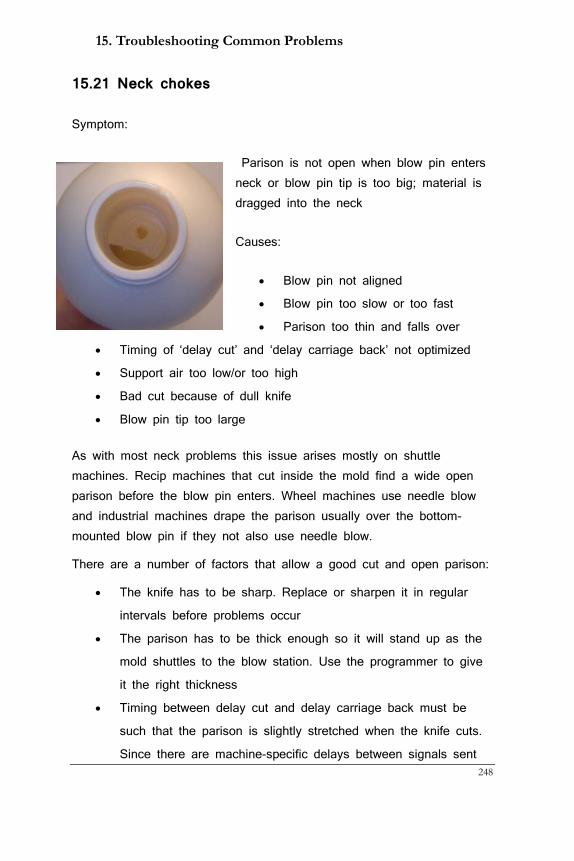
15. Troubleshooting Common Problems
248
15.21 Neck chokes
Symptom:
Parison is not open when blow pin enters neck or blow pin tip is too big; material is dragged into the neck
Causes:
• Blow pin not aligned
• Blow pin too slow or too fast
• Parison too thin and falls over
• Timing of ‘delay cut’ and ‘delay carriage back’ not optimized
• Support air too low/or too high
• Bad cut because of dull knife
• Blow pin tip too large
As with most neck problems this issue arises mostly on shuttle machines. Recip machines that cut inside the mold find a wide open parison before the blow pin enters. Wheel machines use needle blow and industrial machines drape the parison usually over the bottom-mounted blow pin if they not also use needle blow.
There are a number of factors that allow a good cut and open parison:
• The knife has to be sharp. Replace or sharpen it in regular
intervals before problems occur
• The parison has to be thick enough so it will stand up as the
mold shuttles to the blow station. Use the programmer to give
it the right thickness
• Timing between delay cut and delay carriage back must be
such that the parison is slightly stretched when the knife cuts.
Since there are machine-specific delays between signals sent
Guide to Extrusion Blow Molding
249
and actual action there are no fixed times. Close observation is
key
• When the extruder bobs it should start its upwards movement
before the cutting action to stretch the parison in this way
• Head support air can also play a critical role. Too much
support air combined with a long cutting delay can actually
blow a large ‘bubble’ that bursts during cutting and rattles the
parison. Too little air can make the parison fall in on itself
• The speed of the blow pin and the start of blow air can also
play a role. When processing PP blow air should come on
before the blow pin starts moving, with other materials it should
start just before the blow pin enters the mold to reduce noise.
When a lower initial or proportional blow pressure is available
it should always be used to keep the noise down
• As with all neck problems, concentric blow pin alignment is key
15.22 Oval necks
Symptom: When measured at the parting line and 90° to it one or more parameters are out of specification Causes:
• Blow pin not aligned
• Blow pin cooling not working correctly
• Neck is too hot
• Neck is too thick (and hot)
• Shrinkage between parting line and 90° position too large
Solutions: • Align blow pin
• Check blow pin cooling
• Reduce material temperature
15. Troubleshooting Common Problems
250
• Reduce parison thickness in neck area
• Ovalize neck inserts
As outlined in chapter 10.1 the parting line always tends to shrink more than the position 90° to it because cooling channels are further apart. (Of course this does not happen when all cooling channels are as far apart as they are in the parting line but this leads to very ineffective cooling and long cycle times). However, once neck inserts have been ovalized to make up for uneven shrinkage operators have to find the right balance between cooling and material thickness and temperature. Properly aligned blow pins with functioning cooling are a prerequisite. Cooled blow pin tips are recommended when neck wall thickness exceeds 2 mm (0.080”)
15.23 Orange peel Symptom: Scaly, rough container surface Causes:
• Parison too cold or cools without being in close contact to the
mold surface
• Mold too cold for material
• Air trapped in mold
• Air pressure too low
• Moisture on mold surface
Solutions: • Increase head and die temperature or barrel temperature
• Follow resin manufacturer’s instructions for mold temperature
• Check vents and sand-blasted mold surface
• Increase air pressure to 10 to 12 bar (145 to 175 psi)
• Increase chilled water temperature
In most cases when orange peel happens the parison is just too cold to properly form on the mold surface. If you want to run a cold parison (which is generally a good idea) try increasing the blow pressure as a cold parison needs more force to push it against the walls of the mold.
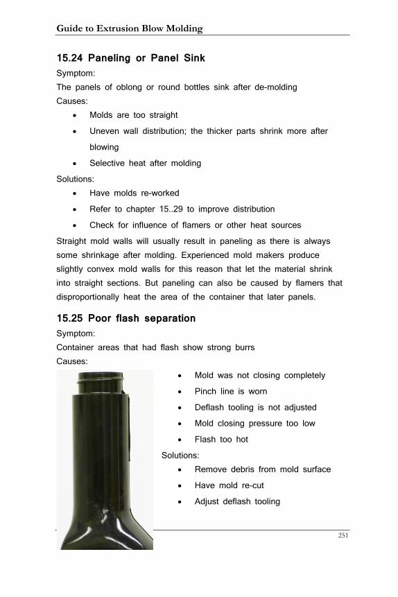
Guide to Extrusion Blow Molding
251
15.24 Paneling or Panel Sink Symptom: The panels of oblong or round bottles sink after de-molding Causes:
• Molds are too straight
• Uneven wall distribution; the thicker parts shrink more after
blowing
• Selective heat after molding
Solutions: • Have molds re-worked
• Refer to chapter 15..29 to improve distribution
• Check for influence of flamers or other heat sources
Straight mold walls will usually result in paneling as there is always some shrinkage after molding. Experienced mold makers produce slightly convex mold walls for this reason that let the material shrink into straight sections. But paneling can also be caused by flamers that disproportionally heat the area of the container that later panels.
15.25 Poor flash separation Symptom: Container areas that had flash show strong burrs Causes:
• Mold was not closing completely
• Pinch line is worn
• Deflash tooling is not adjusted
• Mold closing pressure too low
• Flash too hot
Solutions: • Remove debris from mold surface
• Have mold re-cut
• Adjust deflash tooling
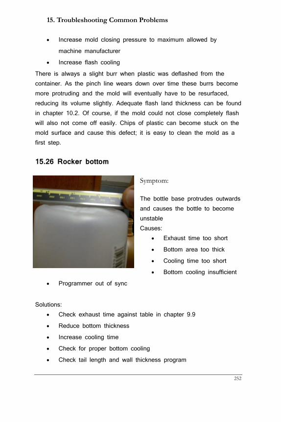
15. Troubleshooting Common Problems
252
• Increase mold closing pressure to maximum allowed by
machine manufacturer
• Increase flash cooling
There is always a slight burr when plastic was deflashed from the container. As the pinch line wears down over time these burrs become more protruding and the mold will eventually have to be resurfaced, reducing its volume slightly. Adequate flash land thickness can be found in chapter 10.2. Of course, if the mold could not close completely flash will also not come off easily. Chips of plastic can become stuck on the mold surface and cause this defect; it is easy to clean the mold as a first step.
15.26 Rocker bottom
Symptom:
The bottle base protrudes outwards and causes the bottle to become unstable Causes:
• Exhaust time too short
• Bottom area too thick
• Cooling time too short
• Bottom cooling insufficient
• Programmer out of sync
Solutions:
• Check exhaust time against table in chapter 9.9
• Reduce bottom thickness
• Increase cooling time
• Check for proper bottom cooling
• Check tail length and wall thickness program
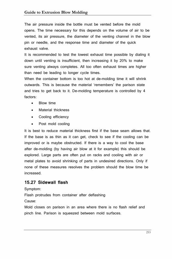
Guide to Extrusion Blow Molding
253
The air pressure inside the bottle must be vented before the mold opens. The time necessary for this depends on the volume of air to be vented, its air pressure, the diameter of the venting channel in the blow pin or needle, and the response time and diameter of the quick exhaust valve. It is recommended to test the lowest exhaust time possible by dialing it down until venting is insufficient, then increasing it by 20% to make sure venting always completes. All too often exhaust times are higher than need be leading to longer cycle times. When the container bottom is too hot at de-molding time it will shrink outwards. This is because the material ‘remembers’ the parison state and tries to get back to it. De-molding temperature is controlled by 4 factors:
• Blow time
• Material thickness
• Cooling efficiency
• Post mold cooling
It is best to reduce material thickness first if the base seam allows that. If the base is as thin as it can get, check to see if the cooling can be improved or is maybe obstructed. If there is a way to cool the base after de-molding (by having air blow at it for example) this should be explored. Large parts are often put on racks and cooling with air or metal plates to avoid shrinking of parts in undesired directions. Only if none of these measures resolves the problem should the blow time be increased.
15.27 Sidewall flash Symptom: Flash protrudes from container after deflashing Cause: Mold closes on parison in an area where there is no flash relief and pinch line. Parison is squeezed between mold surfaces.
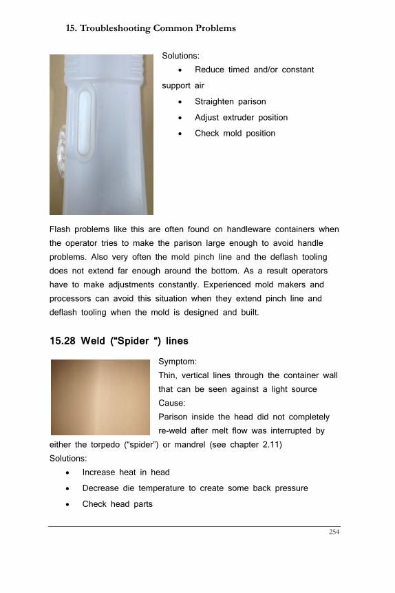
15. Troubleshooting Common Problems
254
Solutions: • Reduce timed and/or constant
support air
• Straighten parison
• Adjust extruder position
• Check mold position
Flash problems like this are often found on handleware containers when the operator tries to make the parison large enough to avoid handle problems. Also very often the mold pinch line and the deflash tooling does not extend far enough around the bottom. As a result operators have to make adjustments constantly. Experienced mold makers and processors can avoid this situation when they extend pinch line and deflash tooling when the mold is designed and built.
15.28 Weld (“Spider “) lines
Symptom: Thin, vertical lines through the container wall that can be seen against a light source Cause: Parison inside the head did not completely re-weld after melt flow was interrupted by
either the torpedo (“spider”) or mandrel (see chapter 2.11) Solutions:
• Increase heat in head
• Decrease die temperature to create some back pressure
• Check head parts
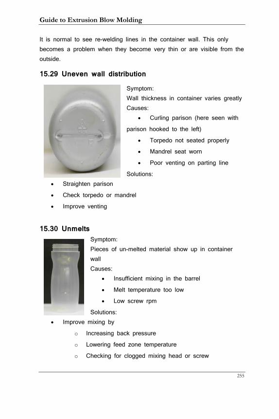
Guide to Extrusion Blow Molding
255
It is normal to see re-welding lines in the container wall. This only becomes a problem when they become very thin or are visible from the outside.
15.29 Uneven wall distribution
Symptom: Wall thickness in container varies greatly Causes:
• Curling parison (here seen with
parison hooked to the left)
• Torpedo not seated properly
• Mandrel seat worn
• Poor venting on parting line
Solutions: • Straighten parison
• Check torpedo or mandrel
• Improve venting
15.30 Unmelts Symptom: Pieces of un-melted material show up in container wall Causes:
• Insufficient mixing in the barrel
• Melt temperature too low
• Low screw rpm
Solutions: • Improve mixing by
o Increasing back pressure
o Lowering feed zone temperature
o Checking for clogged mixing head or screw
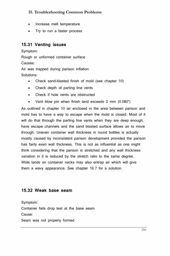
15. Troubleshooting Common Problems
256
• Increase melt temperature
• Try to run a faster process
15.31 Venting issues Symptom: Rough or unformed container surface Causes: Air was trapped during parison inflation Solutions:
• Check sand-blasted finish of mold (see chapter 10)
• Check depth of parting line vents
• Check if hole vents are obstructed
• Vent blow pin when finish land exceeds 2 mm (0.080”)
As outlined in chapter 10 air enclosed in the area between parison and mold has to have a way to escape when the mold is closed. Most of it will do that through the parting line vents when they are deep enough, have escape channels and the sand blasted surface allows air to move through. Uneven container wall thickness in round bottles is actually mostly caused by inconsistent parison development provided the parison has fairly even wall thickness. This is not as influential as one might think considering that the parison is stretched and any wall thickness variation in it is reduced by the stretch ratio to the same degree. Wide lands on container necks may also entrap air which will give them a wavy appearance. See chapter 16.7 for a solution.
15.32 Weak base seam
Symptom: Container fails drop test at the base seam Cause: Seam was not properly formed
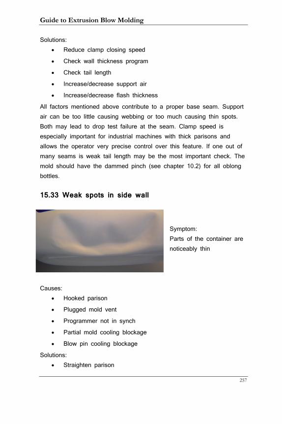
Guide to Extrusion Blow Molding
257
Solutions: • Reduce clamp closing speed
• Check wall thickness program
• Check tail length
• Increase/decrease support air
• Increase/decrease flash thickness
All factors mentioned above contribute to a proper base seam. Support air can be too little causing webbing or too much causing thin spots. Both may lead to drop test failure at the seam. Clamp speed is especially important for industrial machines with thick parisons and allows the operator very precise control over this feature. If one out of many seams is weak tail length may be the most important check. The mold should have the dammed pinch (see chapter 10.2) for all oblong bottles.
15.33 Weak spots in side wall
Symptom: Parts of the container are noticeably thin
Causes:
• Hooked parison
• Plugged mold vent
• Programmer not in synch
• Partial mold cooling blockage
• Blow pin cooling blockage
Solutions: • Straighten parison
15. Troubleshooting Common Problems
258
• Clean vents
• Adjust programmer
• Check mold and blow pin cooling
Weak spots are most often caused by the programmer being out of synch and not getting material where it is needed most. In multi-cavity systems this could be a symptom of uneven tail length or a change in extruder output maybe caused by a change in regrind percentage. It is often a good idea to keep a tail with the correct tail length as reference at the machine. Weak spots can also be caused by parts that are too hot during molding. The parison breaks down locally and stretches a lot thinning it in the process. When the parison has hot spots like that you might look for heater band issues. Heater bands should not be all oriented in the same way. This may look neat but causes that part of the parison that is underneath the area where the heater bands meet to receive less heat, which could lead to a cold spot and a thick part on the container.
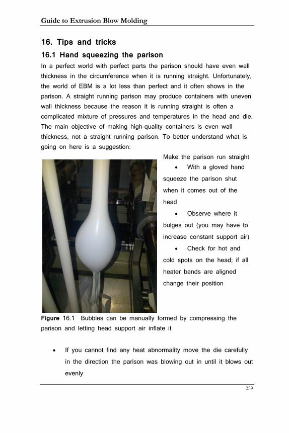
Guide to Extrusion Blow Molding
259
16. Tips and tricks 16.1 Hand squeezing the parison In a perfect world with perfect parts the parison should have even wall thickness in the circumference when it is running straight. Unfortunately, the world of EBM is a lot less than perfect and it often shows in the parison. A straight running parison may produce containers with uneven wall thickness because the reason it is running straight is often a complicated mixture of pressures and temperatures in the head and die. The main objective of making high-quality containers is even wall thickness, not a straight running parison. To better understand what is going on here is a suggestion:
Make the parison run straight • With a gloved hand
squeeze the parison shut
when it comes out of the
head
• Observe where it
bulges out (you may have to
increase constant support air)
• Check for hot and
cold spots on the head; if all
heater bands are aligned
change their position
Figure 16.1 Bubbles can be manually formed by compressing the parison and letting head support air inflate it
• If you cannot find any heat abnormality move the die carefully
in the direction the parison was blowing out in until it blows out
evenly
16. Tips and Tricks
260
• Check the direction of the parison with the new adjustment and
keep in mind that a hooked parison can cause problems with
flash moving up the side of the parison where there is no flash
pocket as well as uneven wall thickness
• Find the optimal compromise between even wall thickness and
flash position
In most cases only small adjustments are necessary. If these become too big to handle investigate the reason of the uneven parison flow. It may be a malfunctioning heater band or dirt in the die or head that is the cause of the problem.
16.2 Increasing back pressure with temperature Material flow in the extruder and head is governed by a number of parameters. Temperature is probably the most important of those and is the easiest to change. Other parameters like channel width or extruder rpm are difficult to change, the former requires a tool modification, the latter a change in output. If the extruder screw and the head are well designed and manufactured it should be straightforward to get a thoroughly mixed, homogeneous melt. However, if things are not perfect or if the material or the number and lay-down ratio of additives make it difficult for this goal it can be beneficial to increase the pressure inside the material. This forces the molecules closer together and can so result in a better melt. The way this works is to create an area with higher resistance in the melt flow than the area before of it. We do this by lowering the respective temperature by 10 to 15°C (18 to 27°F). Two areas are of particular interest:
• The extruder flange
• The area underneath the point where the material has to re-
combine after being split by the mandrel or the torpedo legs
The first method is indicated when there are signs of a non-homogeneous melt such as unmelts, color variations, or other distribution issues. The second method is when spider lines (see
Guide to Extrusion Blow Molding
261
chapter 15.28) are strongly pronounced or lead to container failure. A typical extruder heat layout has increasing temperature (depending on the resin) from the feed to the metering zone and the flange area would be dialed down as indicated. In a mandrel head there may or may not be a heater band in the right location. If there is the method can be used. If there is not it is actually best to raise the temperature across the board to make it easier for the melt to re-knit. Most torpedo heads have a separately controlled heater band just below the spider that can be used.
16.3 Check extruder forward, mold and knife position It is astounding to me how many machines are not set up correctly in the most basic aspects. To recap basic setup includes
• Setting the mold in the center of the platen
• Use stand-off bolts to make up for molds that are shorter than
the platens
• Setting the extruder in both lateral positions to center it with
the mold. Often the parison center line does not coincide with
the mold parting line
• Setting the height and center line (if it is a squeegee knife) of
the knife to get an optimal moil height on shuttle machines
• Setting the extruder (head) height to allow for an optimal cut
• Setting the mold height on an industrial machine to minimize
tail flash
While wheel and recip machines are basically fixed, shuttle and industrial machines allow for a lot of leeway in their setup. Double-sided shuttle machines especially can be cumbersome to re-center when someone has changed the factory setting. In the end, both molds have to end up in exactly the same position underneath the head in both the horizontal (and vertical if they are on a slant) position. Even small differences can create constant problems during production.
16. Tips and Tricks
262
16.4 Check nitrogen pressure without separate gauge The hydraulic accumulator needs to be charged to 100 to 125 bar (1,450 to 1,800 psi) in order to allow oil flow when it is needed (see chapter 8). Signs that it is not up to pressure is a sudden slow-down of machine functions, usually always at the same part of the cycle when most oil is needed. But how can you be sure it is the accumulator and not some other hydraulic mal-function that is at fault? There is a gauge that can be screwed on top of the accumulator that displays the pressure inside it. It is my experience that whenever that gauge is needed it is nowhere to be found. Or sometimes it was never around to begin with. Luckily there is a way to check its pressure without a gauge. Imagine what happens when the pump is turned off but there is pressure in the accumulator and still pressure in the system. Watch the pressure gauge for the main hydraulic pressure and you will see that the needle will retract slowly. During this time system pressure recedes escaping through all the valves and cylinders. As long as there is pressure in the accumulator though the rubber bag expands providing oil to the system. The moment the bag has fully expanded at its set pressure oil flow stops and the gauge will suddenly go to zero. You have to observe this point and when the gauge needle drops to zero this will be the value of the pressure in the bag. If you have more than one accumulator you have to disconnect the others and check them one by one. If the bag is broken the needle will go to zero immediately. A new bag should be in-house as a spare part and while it is time-consuming (and can be frustrating) a new bag can be installed by regular maintenance personnel.
16.5 Vented blow pin Wide container lands may lead to an enclosure of air inside the area covered by the cutting sleeve. This air will prevent proper cooling and the result is one or more depressed land areas that could impair proper sealing. A vented blow pin tip is the solution for these cases.
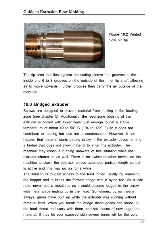
Guide to Extrusion Blow Molding
263
Figure 16.2 Vented blow pin tip
The tip area that lies against the cutting sleeve has grooves to the inside and 6 to 8 grooves on the outside of the inner tip shaft allowing air to move upwards. Further grooves then carry the air outside of the blow pin.
16.6 Bridged extruder Screws are designed to prevent material from melting in the feeding zone (see chapter 5). Additionally, the feed zone housing of the extruder is cooled with tower water just enough to get a stable temperature of about 40 to 50° C (104 to 122° F) so it does not contribute to heating but also not to condensation. However, it can happen that material starts getting sticky in the extruder throat forming a bridge that does not allow material to enter the extruder. The machine may continue running unaware of this situation while the extruder churns on as well. There is no switch or other device on the machine to alarm the operator unless automatic parison length control is active and this may go on for a while. The solution is to gain access to the feed throat usually by removing the hopper and to break the formed bridge with a nylon rod. As a side note, never use a metal rod as it could become lodged in the screw with metal chips ending up in the head. Sometimes, by no means always, gases have built up while the extruder was running without material feed. When you break the bridge these gases can shoot up the feed throat and carry with them ultra-hot pieces of now degraded material. If they hit your exposed skin severe burns will be the very
16. Tips and Tricks
264
likely outcome. Therefore, before attempting this task, make sure that all parts of your body are covered. This means not just gloves, long sleeves, and buttoned-up shirt but also a face mask and cap. While this is a rare occurrence there is no point in taking risks that can seriously hurt you!
16.7 Screw wear Screws can have many base materials and even more coatings depending on the application. Their hardness is adjusted to be somewhat less than the barrel in order to force the screw to wear as it is easier to replace than the barrel. Barrel wear is very expensive to fix and is mostly caused by metallic objects having made their way into the raw material. It is therefore paramount that metal detectors positioned at the incline conveyor to the grinder to prevent this from happening. This also prevents damage to the grinder. Screws may be working for long periods of time depending on the type of material they process. Abrasive additives such as glass-filled materials and mica can drastically reduce the life span of a screw but they are seldom used in EBM. A more common abrasive material is titanium dioxide, the carrier of most white colors. While it is relatively cheap the titanium does wear screw quicker than other colors. Because it takes such a long time and the applications vary it is quite common that worn-out screws are running in a typical production plant. Look for these signs of screw wear:
• Lower output
• Temperature spikes
• Melt not homogeneous
• Poor color dispersion
• Surging
When these signs appear it may be time to remove the screw and measure it. Removal is facilitated by a threaded rod that is inserted into the back of the screw housing. As the screw turns the operator holds on to the rod that then screws itself forward pushing the screw out in
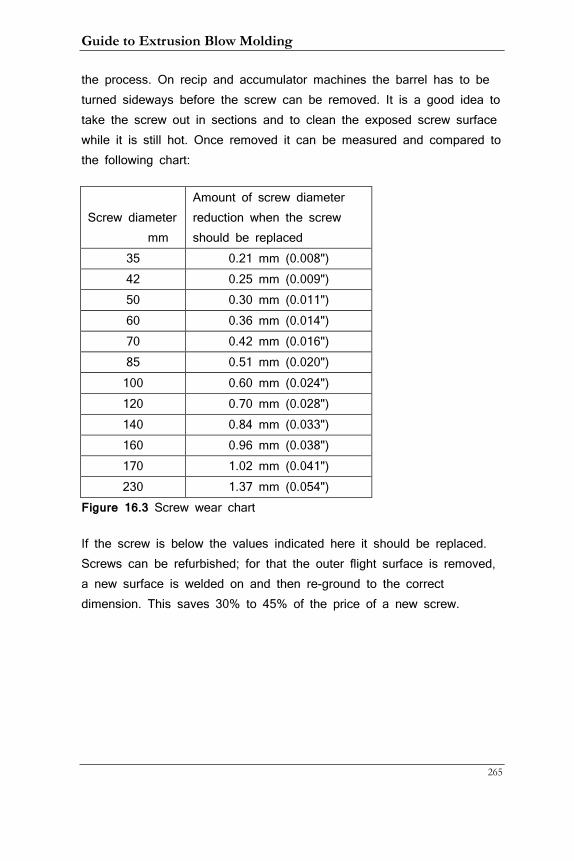
Guide to Extrusion Blow Molding
265
the process. On recip and accumulator machines the barrel has to be turned sideways before the screw can be removed. It is a good idea to take the screw out in sections and to clean the exposed screw surface while it is still hot. Once removed it can be measured and compared to the following chart:
Screw diameter mm
Amount of screw diameter reduction when the screw should be replaced
35 0.21 mm (0.008") 42 0.25 mm (0.009") 50 0.30 mm (0.011") 60 0.36 mm (0.014") 70 0.42 mm (0.016") 85 0.51 mm (0.020") 100 0.60 mm (0.024") 120 0.70 mm (0.028") 140 0.84 mm (0.033") 160 0.96 mm (0.038") 170 1.02 mm (0.041") 230 1.37 mm (0.054")
Figure 16.3 Screw wear chart
If the screw is below the values indicated here it should be replaced. Screws can be refurbished; for that the outer flight surface is removed, a new surface is welded on and then re-ground to the correct dimension. This saves 30% to 45% of the price of a new screw.
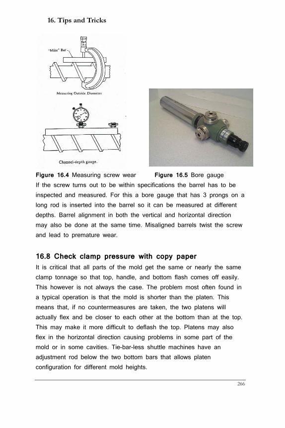
16. Tips and Tricks
266
Figure 16.4 Measuring screw wear Figure 16.5 Bore gauge If the screw turns out to be within specifications the barrel has to be inspected and measured. For this a bore gauge that has 3 prongs on a long rod is inserted into the barrel so it can be measured at different depths. Barrel alignment in both the vertical and horizontal direction may also be done at the same time. Misaligned barrels twist the screw and lead to premature wear.
16.8 Check clamp pressure with copy paper It is critical that all parts of the mold get the same or nearly the same clamp tonnage so that top, handle, and bottom flash comes off easily. This however is not always the case. The problem most often found in a typical operation is that the mold is shorter than the platen. This means that, if no countermeasures are taken, the two platens will actually flex and be closer to each other at the bottom than at the top. This may make it more difficult to deflash the top. Platens may also flex in the horizontal direction causing problems in some part of the mold or in some cavities. Tie-bar-less shuttle machines have an adjustment rod below the two bottom bars that allows platen configuration for different mold heights.
Guide to Extrusion Blow Molding
267
It is certainly possible to make an adjustment and then re-adjust once the machine is running and you can see how well the flash is coming off on the top and bottom. But there is a way to check clamp alignment before the machine is running and this can be a time-saving measure to take. To do this paper, preferably copy paper that comes in rolls is fastened to one side of the mold with tape and the mold is clamped up. The pinch line will leave an impression on the paper that makes it easy to check for any difference in clamp pressure.
16.9 Handle-ware problems on oblong containers Handle-ware containers pose their own special set of challenges. Practically all oblong containers are made with squeegee knives and heavily inflated with head support air. Shuttle machines should have both constant and timed head support air. The flow controls should be piped in such a way that each head has its own set whereas the timed air should affect all parisons on each side of the machine in order to make up for slight inconsistencies between sides. These considerations do not apply to recip and wheel machines of course. The parison has to be large enough so that it covers the handle area. When it is not, the handle may blow out or have weak areas (see “handle webbing” in chapter 15.15). Since most containers are made from HDPE swell is substantial. As outlined in chapter 5.4 swell does not stop when the melt leaves the head but instead continues on and the parison is wider at the bottom than it is at the top. This can lead to a situation where the operator fights a battle between two equally unattractive situations: Either the handle has problems (the parison is too small) or there is protruding flash at the bottom (the parison is too big). The first step is to correctly set the constant head support air. If it is too much at the moment when the knife seals the parison, it will become too big and bottom flash may ensue. If it is too little, bottom webbing may happen. If the timed support air comes in too late the parison may collapse and stick to itself which will create weak spots in the container. Timed head support has to be set so it is off before cutting; otherwise the large parison may touch the mold during mold closing creating the correctly
16. Tips and Tricks
268
named defect “touch mark”. Therefore, these guidelines should be followed:
• Set constant head support air just high enough to avoid bottom
webbing
• If that makes the parison too big at the bottom increase wall
thickness just before and after the cut. This will make the
parison stronger and it will blow out less. You can also run
longer tails as the parison will hang out more
• For the same reason ovalized tooling should be used: Not only
will the corners be better but it also reduces parison diameter
as the heavier sides of the parison fall in
• Control timed support air delay short enough to avoid any
parison sticking
• Experiment with timed support air time and the flow controls to
get the handle right without touch marks
• Look at containers with flash from all cavities. On double-sided
shuttle machines make sure the head is in the center so that
the bottom flash is the same on both sides. On recip and
wheel machine set the head so the flash is the same on either
side of the container. If there is room on the mold to move the
flash more onto the handle side set it a little bit closer to it.
• If the container neck is very close to the edge of the container
the bottom pinch line and flash pocket should be 10 to 15 mm
(0.400” to 0.600”) higher on that side
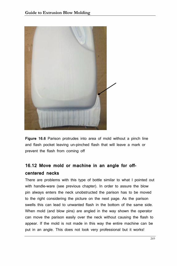
Guide to Extrusion Blow Molding
269
Figure 16.6 Parison protrudes into area of mold without a pinch line and flash pocket leaving un-pinched flash that will leave a mark or prevent the flash from coming off
16.12 Move mold or machine in an angle for off-centered necks There are problems with this type of bottle similar to what I pointed out with handle-ware (see previous chapter). In order to assure the blow pin always enters the neck unobstructed the parison has to be moved to the right considering the picture on the next page. As the parison swells this can lead to unwanted flash in the bottom of the same side. When mold (and blow pins) are angled in the way shown the operator can move the parison easily over the neck without causing the flash to appear. If the mold is not made in this way the entire machine can be put in an angle. This does not look very professional but it works!
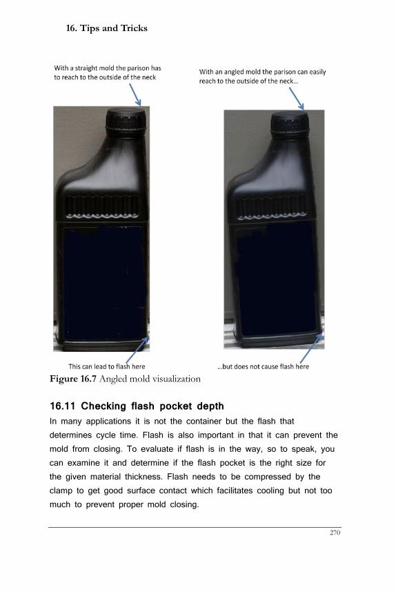
16. Tips and Tricks
270
Figure 16.7 Angled mold visualization
16.11 Checking flash pocket depth In many applications it is not the container but the flash that determines cycle time. Flash is also important in that it can prevent the mold from closing. To evaluate if flash is in the way, so to speak, you can examine it and determine if the flash pocket is the right size for the given material thickness. Flash needs to be compressed by the clamp to get good surface contact which facilitates cooling but not too much to prevent proper mold closing.
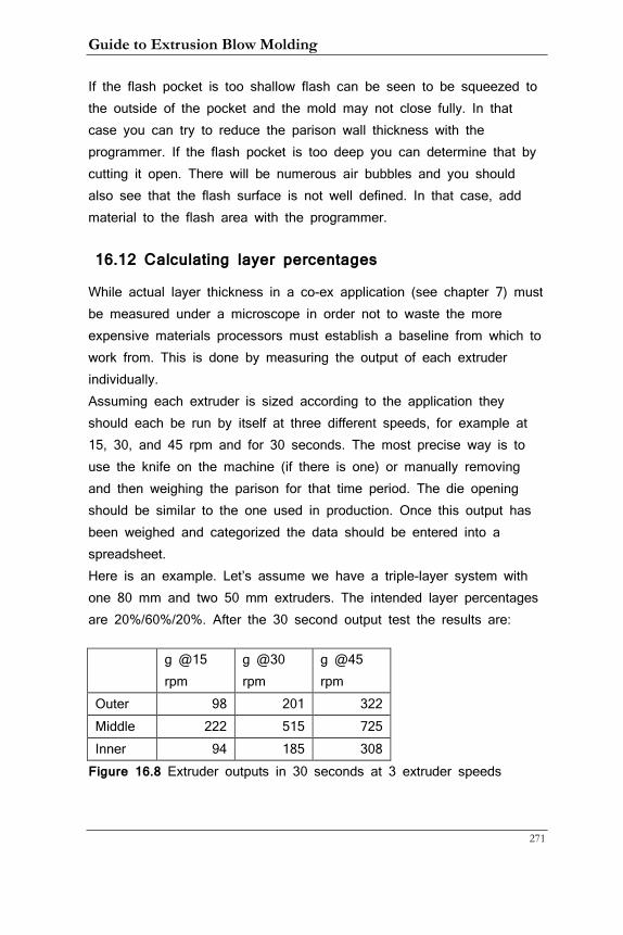
Guide to Extrusion Blow Molding
271
If the flash pocket is too shallow flash can be seen to be squeezed to the outside of the pocket and the mold may not close fully. In that case you can try to reduce the parison wall thickness with the programmer. If the flash pocket is too deep you can determine that by cutting it open. There will be numerous air bubbles and you should also see that the flash surface is not well defined. In that case, add material to the flash area with the programmer.
16.12 Calculating layer percentages
While actual layer thickness in a co-ex application (see chapter 7) must be measured under a microscope in order not to waste the more expensive materials processors must establish a baseline from which to work from. This is done by measuring the output of each extruder individually. Assuming each extruder is sized according to the application they should each be run by itself at three different speeds, for example at 15, 30, and 45 rpm and for 30 seconds. The most precise way is to use the knife on the machine (if there is one) or manually removing and then weighing the parison for that time period. The die opening should be similar to the one used in production. Once this output has been weighed and categorized the data should be entered into a spreadsheet. Here is an example. Let’s assume we have a triple-layer system with one 80 mm and two 50 mm extruders. The intended layer percentages are 20%/60%/20%. After the 30 second output test the results are:
g @15 rpm
g @30 rpm
g @45 rpm
Outer 98 201 322 Middle 222 515 725 Inner 94 185 308
Figure 16.8 Extruder outputs in 30 seconds at 3 extruder speeds
16. Tips and Tricks
272
Multiplying these numbers by 120 results in hourly output: kg/ hour kg/ hour kg/ hour Percent Outer 11.8 24.1 38.6 24% Middle 26.6 61.8 87.0 54% Inner 11.28 22.2 36.96 23%
Total 162.6
Figure 16.9 Extruder outputs per hour and percentage of total
By dividing the individual outputs by the total we also get the percentages. It shows that the middle extruder will have to run somewhat faster than the others in order to get the intended percentages. To calculate this more exactly let’s compute the grams per revolution for the three output numbers. This will smoothen out any errors we made when we cut or manually ripped off the parison as this is not as exact as one could wish. For the outer extruder this would look like this:
(98 / 15 + 201 / 30 + 322 / 45) / 3 * 120 = 0.82 kg/h/rpm For the middle and inner layer these numbers are 1.92 and 0.77 respectively. Assuming we run a 34 g container in 8 cavities @ 12 seconds cycle time and 25% flash the total output is: 3600 / 12 * 8 * .034 * 1.25 = 102 kg/h The intended percentages result in: 102 * 20% = 20.4 kg/h 102 * 60% = 61.2 kg/h The three extruders should then run at these speeds: Outer: 20.4 / 0.82 = 24.8 rpm Middle: 61.2 / 1.92 = 31.9 rpm Inner: 20.4 / 0.77 = 26.5 rpm This will not be completely correct but will be a very good starting point. Fine-tuning after microscopic examination will correct any inaccuracies.
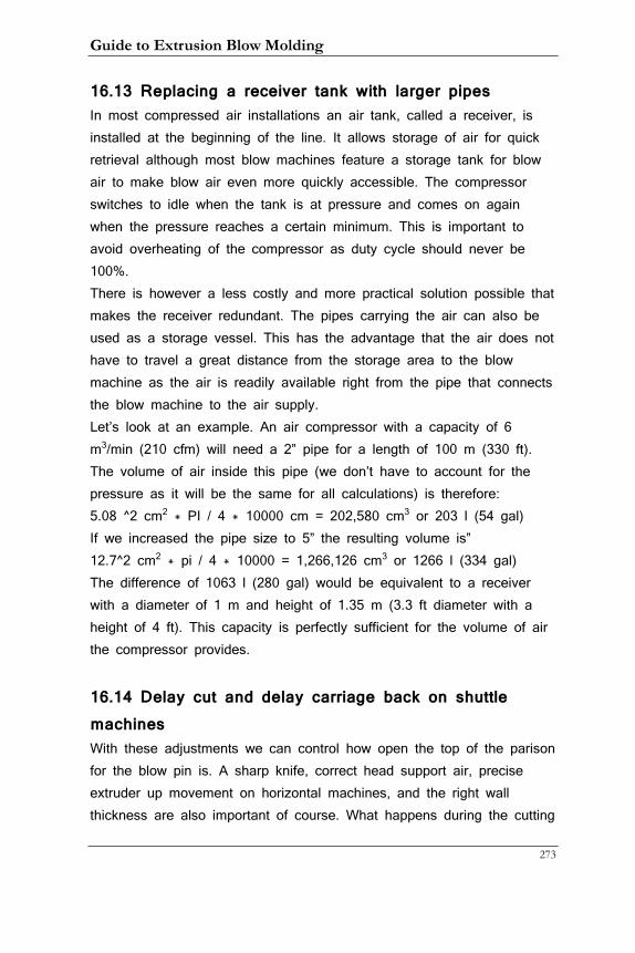
Guide to Extrusion Blow Molding
273
16.13 Replacing a receiver tank with larger pipes In most compressed air installations an air tank, called a receiver, is installed at the beginning of the line. It allows storage of air for quick retrieval although most blow machines feature a storage tank for blow air to make blow air even more quickly accessible. The compressor switches to idle when the tank is at pressure and comes on again when the pressure reaches a certain minimum. This is important to avoid overheating of the compressor as duty cycle should never be 100%. There is however a less costly and more practical solution possible that makes the receiver redundant. The pipes carrying the air can also be used as a storage vessel. This has the advantage that the air does not have to travel a great distance from the storage area to the blow machine as the air is readily available right from the pipe that connects the blow machine to the air supply. Let’s look at an example. An air compressor with a capacity of 6 m3/min (210 cfm) will need a 2” pipe for a length of 100 m (330 ft). The volume of air inside this pipe (we don’t have to account for the pressure as it will be the same for all calculations) is therefore: 5.08 ^2 cm2 * PI / 4 * 10000 cm = 202,580 cm3 or 203 l (54 gal) If we increased the pipe size to 5” the resulting volume is” 12.7^2 cm2 * pi / 4 * 10000 = 1,266,126 cm3 or 1266 l (334 gal) The difference of 1063 l (280 gal) would be equivalent to a receiver with a diameter of 1 m and height of 1.35 m (3.3 ft diameter with a height of 4 ft). This capacity is perfectly sufficient for the volume of air the compressor provides.
16.14 Delay cut and delay carriage back on shuttle machines With these adjustments we can control how open the top of the parison for the blow pin is. A sharp knife, correct head support air, precise extruder up movement on horizontal machines, and the right wall thickness are also important of course. What happens during the cutting
16. Tips and Tricks
274
process is that the parison is caught by the mold halves. If there is neck flash it is caught at the top and bottom, if the bottle is captively blown, just at the bottom. The delay cut time determines how long the parison is allowed to accumulate with the mold closed or almost closed depending on the mold closing speed. This in turn will or will not create a ‘bubble’, that is a portion of the parison that is inflated by constant head support before the knife cuts it open. It is dependent on many factors if a particular application benefits from any bubble or the size of it. Only close observation can tell and it is often necessary to try out several delay times. The carriage movement can be used to stretch the parison slightly on slanted carriage movement machines where on horizontal machines this task is done by the bobbing extruder. Stretching the parison is not always the right approach. While it helps preventing the parison extruding from the head to re-connect with the cut parison it can sometimes create problems with keeping the parison open. It takes close observation to see how the parison forms and trial and error with the timers to get the optimal setting.
Guide to Extrusion Blow Molding
275
17. Blow Molding Glossary
Accumulator head – Head with storage space for extruded materials that form the parison prior to push out facilitated by the push-out cylinder Accumulator hydraulic – Pressure storage vessel to assist hydraulic operations at maximum flow demand. Can be a bladder or piston type. Additive – Formulations blended into bulk materials (UV stabilisers, Fire retardants, Anti static’s). Air pressure – Mains supply pressure from compressor, which can be regulated for pre-blow and main blowing while inflating the parison. Ambient – Atmospheric temperature and humidity as well as air pressure varies throughout the day and can affect molding conditions. Annulus – Gap between pin and die that determines the parison wall thickness. Anti-static – Additive that discharges the static build up in a finished molding. As a device it is used to remove static from extruding parisons Auto-deflashing – Mechanism that punches the flash from the molded product after being transferred from the blowing station. Auto-unscrewing – Mechanism that is driven by a hydraulic motor drive to unscrew internal threading mandrels. Back plate – Mold back plate holds the tool to the machine platen. Barrel extruder – Heated outer sleeve of extruder in which screw rotates. Batch – Quantity of moldings to be manufactured. Also batch of resin. Blender – Mixing unit for raw materials; can be independent system or hopper mounted. Blow needle – Punctures parison and introduces air into it Blow pin – Metal tube, which conveys high-pressure air into the mold, inflating the parison. Pins can be fixed top and bottom Blow ratio, also called stretch ratio - The relationship between the size of the parison and finished product sizes, expressed as a ratio
17. Glossary
276
Blow time – Period during the molding cycle when the main blowing pressure is applied. Breaker plate – A perforated plate located at the screw tip discharge from the extruder. Used to support a screen pack or create backpressure to assist in master batch colour dispersion. Bushing – Alignment sleeve locating guide pins to match up tool cavities. Also equivalent to die. Bulk density – Total weight of material that fills 1 litre volume – given as kg/l Calibration – Blow pin system used to consolidate and cut off material that forms an external neck seal face. Capacity – Machine head volume normally in litres or pounds. Also plasticizing capacity of extruder or number of products being produced (machine capacity) or volume of one container as in overflow volume or fill volume. Captive blow molding – When the parison fits into the neck of a bottle Chiller – Supplies refrigerated cooling water to the process. Co-extrusion – Multi layered parison. Colorant – Additive that provides the desired color to the finished products. Compressor – Machine that supplies compressed air to the system. Compression molding – Sections in the molding tool that forms solid features, typically lugs, brackets and threaded necks. Compression zone – Section of extruder where the channel volume reduces, compacting the dry material pellets and removing air. Contamination – Foreign bodies in the plastic melt. Cooling table – Water or air fan cooled table for flash cooling. Co-polymer – Mixture of materials Cross linking – Atoms in plastics form bridges to each other. Curl up – On push out material rolls outwards forming a tire of material at die tip. Cutting sleeve – Working edge of blow pin that cuts and separates neck flash from molded product.
Guide to Extrusion Blow Molding
277
Cycle time – The total machine molding time to produce a complete molding. Cyclone – Fan used in material reclaim units that transports re-grind. Date stamp – Embossed date, usually year and month into molding surface to give traceability. Daylight – Maximum and minimum distance between machine platen. Deformable die system - Ovalizes the parison during push out by manipulating the die shape using hydraulic cylinders. Degradation – Decomposed materials through overheating during extrusion. De-molding – Removing molded product from tool and machine. Density – Specific gravity of material. Die – External tooling that sizes the outside diameter of the parison. Die gap – The annulus between pin and die. Die lines – Vertical striations in parison surface caused by obstacle in melt flow. Die set – Comprises pin, die, pin holder, and extension pieces. Die swell – parison diameter increase when it leaves the die. Swelling can be unto 65 percent of die size. Dispersion – Complete homogeneous mixing of the additives into the bulk material. Doughnut – Material that curls inwards during push-out or extrusion. Draft – Small angle one to two degrees incorporated into the tool in line of draw to assist with de-molding. Draw down (also called sagging)– During parison formation the extruded mass will stretch due to its own weight and gravitational effects. Ejector – Push-off mechanism in molding tool, can be pins or plate. Electrostatic – Residual static that is present in finished products or parison. Exhaust time – Time set during cycle to completely vent all blowing pressure from the product. Extruder – Plastic material melting unit, consisting of Screw and Barrel. Extruder flange – Two collars that bolt together to hold in place the extruder and machine head.
17. Glossary
278
Extruder throat= First section of extruder where material is fed. Finishing machine – Special purpose equipment designed to meet end product finishing requirements. Flash – Excess material produced during molding. Flash pocket – Section in blow mold tool that accommodates the excess materials produced during molding. Flaming – Flame treatment to product surfaces prior to screen or pad printing. Flight – The helical spiral of the extruder screw. Flight depth – Depth of extruder screw helical spiral. Flow control – Can apply to hydraulics, pneumatics or head parison push out speeds. Flow marks – Result from dirty die face showing vertical lines in the finished product. Gravimetric blender – Material-mixing system which can be very accurately controlled as individual weighed batches are used for each blend. Granulator – Machine designed to recycle flash, off-cuts and scrap moldings by size reducing them to regrind Granule (pellet) – Particle of plastic raw material. Grinder Screen – The re-chip sizing mesh used in the material reclaiming operation. Gripper unit – Product take out mechanism. Guard – Machine covers for operator protection. Guide pin – Mold cavity alignment locators. Head – Section of machine that forms the parison. Heater Band – Electric element that supplies heating to the extruder and machine head. Heat stabiliser – Additive blended into base polymer to reduce thermal decomposition during the extruding of the material. Heating zones – Sections of the extruder and head that are heated and temperature controlled individually. Hinge – Molded feature that joins lid to base in case manufacture. Hopper – Intermediate storage of material for extruder feed.
Guide to Extrusion Blow Molding
279
Hopper loader – Equipment that conveys material to the machine extruder can be vacuum, blown, or screw elevated systems. Homogenous – Complete blend of material with good dispersion of master-batch evenly distributed throughout the melted material. Hypodermic – Blow pin needle used for final blowing. In-mold cutting – Lost heads and surplus material are cut for their removal. The cutting is normally hydraulic actuation cylinders and usually occurs at the end of the molding exhausting cycle of the product while it is still in the mold. In mold labeling – Method of affixing instruction labels during the molding operation. Labels are vacuum placed into the mold cavities prior to push out and mold closing. Insert – Component that is molded into the wall of the molded product by placement into the mold prior to mold closing. Usually thread forms or brackets. Internal thread – Thread formed around a threaded mandrel for fitting screw bung. Jig – Holding fixture used during product finishing operations. Land – Small flat that sizes the final diameters of the pin and die to avoid a featheredge.. Leak test – Special purpose equipment that is situated in a production line to pressure or electrical discharge test for holes in the finished molded product. L/D ratio – Extruder screw length to diameter ratio. LVDT – Linear voltage displacement transducer unit used to monitor machine movements, linked to machine control system for adjustments. Locking pressure – Mold closing pressure. Lost head – Section of molded product that is required during molding to close off parison envelope inside tool, which is subsequently removed for recycling from the finished molding. Maddox – Type of screw tip that assists with material mixing of colorants.
17. Glossary
280
Mandrel – Thread forming blow pin used to create internal thread forms and convey blowing air into the blow-molding tool. Also inner part of mandrel head and as another name for pin. Master batch – Color additive Melt – Molten material. Melt fracture – parison molding defect caused by over shearing during material push out. Push out speed too fast or melt temperature too high. MFI (or MI)– Melt flow index of the material. Melt strength – Ability of the molten material to resist draw down during parison formation. Metal detector – System used to monitor contaminated materials, removing and rejecting any metal elements automatically. Moil – Flash on top of the bottle when the bottle is blown captive. When flash protrudes outside the neck it is called neck flash Moog programmer– Special purpose parison control unit. Mold – Tooling that produces desired shapes. Molding pressure – The final air blowing pressure used during molding. Moving ends – Hydraulically actuated mold plates, that allow undercuts in the end of products to be molded Multi cavity – More than one cavity. Multi layer – Co-extruded parison consisting of at least 2 different material layers. Neck insert – Two identical half impressions metal inserts that form the closure system external features, situated in each mold half. Opacity – Level of clarity after molding. Over blowing – Excessive flash generated around the mold split line. Ovalization – Profiling of pin or die to induce more material flow creating parison thickness at specific points. Pad printing – System of product decoration that uses rubber sponge pad to collect ink impressions and deposits these onto product surface. Parison – Tube of molten plastic formed by the pin and die in the machine head.
Guide to Extrusion Blow Molding
281
Parison control – Hydraulic unit that varies the annulus size between the pin and die to increase or decrease the parison wall thickness. Part mover – Hydraulic actuation of moving parts situated in the blow molding tool. Pellets –Plastic granules. Permeation – The egress of stored contents through the plastic walls, typically example solvents. Pierce and blow – Action of blow needle to enable main blowing pressure into molding. Pin (also called mandrel) – Internal tooling of the parison forming head. Pineapple tip – Type of extruder screw tip that mixes the colorants with a chopping action. Pinch line – The cutting edges in the molding tool that cuts through the plastic and re-welds the two wall halves of the parison during the molding cycle. Pinch off – Re-weld line that separates the molded product from the flash. Also mold cutting edge. Pinch off terminations – The end points of the re-welded material that normally form into a very thick section, being the gathering of two-wall thicknesses. Pinch plates – Spring or pneumatically operated plates used during pre-blowing to close off one end of the parison to create a material envelope. Platen – Machine mounting plate for the blow molding tools. Plasticizing capacity – Mass of material that can be extruded in a fixed period of time. Post molding distortion – Product shape defects caused by varying wall thickness, which is the result differential shrinkage. Pre-blow – Initial inflation of the parison before mold closing and main blowing Proportional hydraulics – Hydraulic cylinder movements, which are precisely controlled by balanced flow of oil. Usually a Moog type control valve. Push out – Formation of the parison.
17. Glossary
282
Push out speed – The rate of parison formation from the machine head. Push out time – Time in seconds taken to form the parison. Purge plug – Screwed plug that is removed to speed up the color change process. PWDS – parison wall deflection system, that ovalises the parison during push out by manipulating the die shape using hydraulic cylinders. Quick fit coupling – Hydraulic, pneumatic and water connections. Raw material – Base polymer normally supplied in natural form. Radii – Essential feature in the design of blow-molded parts; avoid sharp corners with a radius. Re-grind –Reclaimed materials by the granulation process. Recycling – Materials that are reclaimed for reprocessing Reject – Scrap molding, any product that fails to meet the quality requirements. Re-weld – Re-joining of the two parison walls during molding. Rheology – Study of material flow characteristics. Rout – Method of cutting apertures into molded products. RPM – Revolutions per minute, motor, extruder speeds. Scrap – Any and all, recyclable materials – defective moldings. Screen pack – Fine gauze mesh fitted to breaker plate to create backpressure to the extrusion process and to remove small contaminants in the bulk material. Screen printing – Product decoration method using fine silk screens to print directly onto plastic surfaces. Screw – Helically grooved rotating member housed in the barrel of an extruder. Screw elevator – Material-conveying system using rotation screw, good for powder, LPDE and EVA type materials. Screw tip – Working part of the extruder that mixes the colorants, Maddox or Pineapple type. Seepage – Material that creeps out of the head push out piston, usually depicts wear. Shot weight – The total parison weight required to mold a product.
Guide to Extrusion Blow Molding
283
Short shot – parison length insufficient to mold product. Shrinkage – The overall reduction in product size after molding and normalization. Amount varies depending on which material is being molded, de-molding temperature and finished wall thickness. Spider legs – Support legs for torpedoes Spider lines – Weak spots in the material melt that retain memory of the re-welding action in the machine head. Spin welding – Method of attaching components using friction. Spreading device – Pneumatically operated pins that manipulate the bottom of the fully extruded parison to assist with material distribution in the base of a product. Stress cracking – Degradation of plastic caused by chemical attack, which is aggravated by top loading and internal pressure forces. Striker plate – The working hardened anvil shells that allow separation of flash from the molded neck of the product. Stripper plates – Anvils used to pull products off a blow pin or de-molded parts from the molding tool. Take out unit – Product removal system. Temperature controller – Instrument that is set at a temperature point that is connected to a thermo-couple which feeds back the working temperature of the zone being controlled. Thermocouple – Device that monitors machine heating zone temperatures. Threads – Internal or external, which are molded to accept screw cap or bung. Thermage – Method of decoration using electrostatic discharging of images onto the product. Torpedo – The internal section of the machine head that forms the melted material into a tube shape to produce the parison. Top load – Forces created by stacking height of products. Torque – Radial force used during tightening of closures. Touch screen – Machine control setting system linked to PC. Transducer – Melt temperature and pressure monitoring instrumentation.
17. Glossary
284
Transition section – Section of the extrusion screw where dry granules are formed into a melted condition. Under-blowing – Finished products lack definition and display air entrapment on external surfaces. Unscrewing device – Hydraulic motor driven system that allows automatic retraction of internal thread forming mandrels. Ultra sonic welding – Special purpose system for attaching ancillary components to molded parts using high vibration techniques. UV degradation – Deterioration of the product when exposed to sunlight. Ultraviolet light embitters the product surface, which will split on impact. UV stabiliser – Additive that is blended into the bulk material that inhibits surface attack by sunlight. Vents – Slotted air escape features in the blow molding tool, positioned where air is likely to be trapped when parison is inflated during blowing. Viscosity – Resistance to flow of the molten material. Wall thickness – The material thickness that is measured at any point of the finished product. Warpage – Distortion caused by uneven wall thickness or hot spots in the molding tool. Watermarks – Surface defects in the molded product invariably caused by condensation due to atmospheric conditions on the mold surface. Wax – Decomposed material that is extremely overheated. Webbing – Inclusions in the molded product caused by poor blowing ratio of the extruded parison to finished product size. Weight – The finished weight of the molded product. Weld line – The point where the two parison halves are reformed by the mold closing action, at the pinchline. Zone – Section of extruder or head that is heated and temperature controlled. Unit Conversions 100 kilopascal (kPa) = 14.5 psi = 1 bar 1 kilonewton (kN) = 1000 Newtons (N) = 102 kg = 224 lbs
Guide to Extrusion Blow Molding
285
Index
A
a brand owner · 190
AC motors · 40
accumulator head · 28, 57, 63, 73, 79, 114, 124, 161
Accumulator head machines · 17
air · 17, 28, 32, 42, 47, 52, 57, 61, 91, 106, 111, 112, 114, 115, 116, 117, 119, 120, 121, 123, 124, 136, 142, 143, 144, 155, 163, 170, 171, 173, 183, 193, 194, 195, 197, 199, 203, 207, 209, 213, 223, 224, 226, 229, 230, 231, 233, 235, 239, 241, 243, 246, 247, 248, 249, 251, 252, 255, 257, 260, 261, 265, 266, 269, 271, 273, 274, 278, 281, 282
Aluminum · 114, 222
amorphous · 93, 99, 105, 111
anti-freeze · 114, 191, 198
B
Bad parting lines · 230
Bagging machine · 219
barrel · 40, 41, 42, 96, 97, 100, 102, 103, 107, 108, 156, 234, 235, 240, 249, 254, 262, 264, 280
Barrels · 42
barrier · 128, 129, 130, 131, 133, 134, 180, 197, 214
beryllium copper · 114
black spots · 245
blow dome · 64, 208
Blow needle · 122
blow pin · 13, 19, 20, 22, 24, 25, 27, 47, 48, 49, 50, 52, 61, 64, 72, 77, 119, 120, 121, 122, 143, 154, 157, 162, 163, 185, 186, 208, 225, 235, 246, 247, 248, 249, 251, 254, 256, 260, 261, 267, 271, 274, 278, 281
blow ratio · 111
Blow-and-drop machines · 18
bottom rocker · 168
Bottom webbing · 231
Box packer · 216
branches · 92
Bridged extruder · 231
Index
286
bubble · 117, 119, 229, 247, 272
bulk density · 210, 229
bushing · 59, 70, 75, 174, 175
C
CAD · 179, 180
calibration · 27, 30, 49, 64, 69, 158
Capacitive thickness gauge · 188
captive blowing. · 110
carbon · 87, 88, 89, 90, 91
carriage · 13, 17, 18, 19, 20, 21, 23, 24, 25, 28, 46, 63, 65, 66, 72, 118, 119, 183, 215, 226, 243, 247, 271, 272
cast-iron · 114
center-fed · 54
chiller · 40, 193, 194, 195, 196, 197, 198, 200, 201, 202, 203, 222, 223, 232
chlorine · 87, 90, 91, 92
clamp pressure · 264
Co-ex · 9, 125, 126, 133, 134
color · 12, 34, 102, 108, 126, 127, 128, 129, 131, 153, 155, 156, 204, 205, 236, 237, 258, 262, 274, 280
compatible materials · 126, 128
compression · 78, 100, 101, 108, 137, 142, 186, 229
Compressor · 11, 142, 203, 274
Condensation marks · 232
conductivity · 113, 165, 199, 221, 222
container · 15, 16, 22, 27, 28, 30, 31, 32, 33, 34, 35, 36, 47, 57, 58, 59, 61, 62, 65, 66, 67, 68, 74, 78, 80, 81, 83, 84, 93, 94, 95, 103, 107, 108, 110, 111, 112, 113, 115, 120, 121, 122, 127, 128, 129, 130, 134, 150, 161, 162, 163, 166, 168, 170, 171, 172, 174,늬175, 176, 177, 179, 180, 181, 182, 183, 184, 188, 189, 190, 191, 192, 210, 212, 214, 216, 220, 221, 222, 226, 229, 231, 232, 233, 234, 235, 236, 237, 240, 241, 244, 245, 249, 250, 251, 252, 253, 254, 255, 256, 258, 260, 265, 266, 268, 270, 274
Container deformation · 234
Container rupture · 235
Contamination · 233
Converging tooling · 159, 160
converter · 31, 141, 190, 191
Guide to Extrusion Blow Molding
287
Converters · 215
cooling requirements · 194, 200, 202, 221
Corona · 11, 212, 213
corrugated design · 173
crystalline · 93, 99
crystallinity · 93
crystallization · 92
Curtaining · 235
cycle time · 31, 32, 34, 37, 64, 66, 68, 72, 85, 108, 163, 168, 172, 201, 210, 215, 217, 221, 222, 223, 268, 270
cyclone · 206
cylinder · 23, 26, 27, 43, 46, 50, 51, 52, 54, 62, 64, 69, 71, 75, 76, 79, 84, 120, 135, 136, 138, 139, 140, 158, 159, 160, 162, 168, 273, 279
D
DC motors · 40
Deflash · 21, 30, 250
Density · 9, 94, 275
desiccant · 209
detabbers · 19, 172
dew point. · 223
Die · 7, 9, 12, 33, 59, 60, 70, 99, 108, 159, 237, 238, 246, 275
die head · 14, 54, 69, 99
Discoloration · 236
dispersion · 108, 262, 274, 277
Diverging tooling · 60, 160, 176
Doughnut formation · 238
Drop Test · 11, 189
Dryer · 209
Drying temperature · 210
Dull finish · 239
E
ethane · 88, 89
ethene · 88
EVOH · 129, 131
extruder · 10, 12, 13, 14, 17, 18, 26, 28, 31, 33, 40, 54, 73, 77, 78, 79, 91, 94, 99, 100, 102, 103, 108, 118, 119, 127, 131, 133, 134, 153, 155, 156, 161, 201, 205, 206, 229, 231,
Index
288
237, 238, 243, 245, 246, 247, 252, 256, 258, 259, 261, 269, 270, 271, 272, 273, 274, 276, 277, 279, 280, 282
Extruder · 7, 9, 33, 39, 99, 161, 269, 270, 275, 276, 277
extrusion head · 28, 33, 54, 97, 106
F
feeding · 100, 205, 261
Fines · 242
Finite Element Analysis · 180
Flamers · 212
flash · 12, 13, 16, 19, 22, 27, 28, 29, 30, 32, 33, 37, 49, 50, 61, 62, 63, 74, 78, 80, 110, 161, 166, 168, 172, 173, 174, 201, 206, 207, 210, 211, 215, 230, 238, 239, 241, 246, 250, 252, 255, 258, 259, 264, 265, 266, 267, 268, 269, 270, 273, 274, 276, 278, 279, 281
Flash · 10, 33, 78, 120, 172, 240, 250, 252, 268, 276, 278
Fluorination · 11, 214
fluorine · 87, 214
G
Gaylord · 204, 241
Gels · 241
Graphical User Interface · 145
Gravimetric · 149, 205, 276
grinder · 206, 207, 234, 241, 245, 262
gripper · 24, 28, 216, 217
grippers · 22, 27, 215, 216, 235
grooved extruder · 40
H
Hall effect sensor · 188
Handle webbing · 242
Handle-ware · 265
hang strength · 106, 236
hazardous · 191
HDPE · 30, 32, 34, 38, 40, 42, 87, 88, 89, 90, 92, 94, 98, 101, 102, 107, 110, 113, 168, 170, 181, 201, 222, 265
head support air · 52, 115, 121, 265
Head temperatures · 107
heart-shaped curves · 57
Guide to Extrusion Blow Molding
289
heater band · 97, 107, 146, 147, 154, 156, 256, 258, 259
Heater band · 39, 41, 256
hole vent · 170, 171, 254
Holes · 243
hook · 20, 25, 157
hopper · 40, 99, 102, 205, 209, 210, 211, 233, 261, 273
horse-shoe design · 167
Hot Knife · 8, 53
huff and puff · 114
Hydraulic motors · 40
Hydraulics · 10, 135
hydrogen · 87, 88, 90
hygroscopic · 209
I
IML · 8, 65, 66
In Mold Labeling · 8, 65
Intermediate Bulk Containers (IBCs) · 15
K
knife · 8, 13, 23, 50, 51, 52, 53, 54, 73, 74, 77, 78, 115, 117, 118, 119, 143, 208, 225, 231, 238, 244, 247, 259, 265, 269, 271
L
L/D ratio · 100, 101, 102, 192, 277
layer percentages · 269
Layer thickness · 134
LDPE · 30, 87, 90, 91, 93, 94, 101, 107, 110, 113, 168, 170, 181, 201, 222, 237, 245
leak test · 220
leak tester · 22, 220, 221
Liner · 217
M
mandrel · 54, 56, 57, 58, 59, 60, 61, 70, 75, 109, 115, 153, 156, 239, 253, 254, 258, 259, 277, 278, 279
Mandrel · 8, 56, 133, 156, 159, 253, 278
Material Data Sheet · 210
Material degradation · 245
Index
290
Melt Flow Index · 9, 95
Melt Index · 9, 94, 95
metering · 42, 100, 101, 107, 108, 138, 139, 229, 259
Methane · 87, 88
mixing heads · 99, 102
moil · 259
moils · 19
Moisture · 12, 142, 245, 246, 249
Moisture bubbles · 245
moisture loss · 128
mold · 13, 16, 17, 18, 19, 20, 21, 22, 23, 27, 28, 31, 34, 36, 37, 43, 44, 46, 49, 50, 53, 60, 63, 64, 65, 66, 72, 73, 78, 79, 81, 84, 86, 92, 93, 94, 109, 110, 111, 112, 113, 114, 115, 116, 117, 118, 119, 120, 121, 122, 123, 153, 154, 155, 156, 157, 158, 161,늬163, 165, 166, 168, 169, 170, 171, 172, 173, 179, 180, 181, 183, 186, 192, 198, 199, 200, 222, 223, 225, 226, 230, 231, 232, 233, 234, 235, 239, 243, 244, 246, 247, 248, 249, 250, 251, 252, 254, 255, 256, 259, 264, 265, 266, 267, 268, 271, 273, 275, 276, 277, 278, 279, 280, 282
multi-cavity · 31, 50, 51, 76, 166, 256
N
neck · 16, 19, 22, 24, 28, 32, 33, 47, 49, 50, 61, 64, 67, 68, 77, 78, 81, 109, 110, 114, 117, 119, 121, 122, 153, 157, 162, 165, 166, 167, 168, 174, 180, 182, 184, 185, 186, 187, 208, 220, 225, 246, 247, 248, 266, 267, 271, 274, 278, 281
Neck “Ears · 12, 246
Neck chokes · 12, 246
neck flash · 19, 49, 61, 180, 271, 274, 278
Nylon · 28, 32, 101, 107, 129, 210, 211
O
off-centered necks · 267
Operator Interface · 145
Orange peel · 249
orientation · 107, 111, 116, 182, 187, 215
Oval necks · 12, 248
ovalization · 167, 174, 223
oxygen · 87, 128, 182, 212, 213
Guide to Extrusion Blow Molding
291
P
palletizer · 218, 219
panel sink · 120, 168, 187
Paneling · 12, 249
parison · 13, 14, 17, 18, 22, 23, 26, 28, 33, 37, 38, 47, 50, 51, 52, 54, 55, 56, 57, 58, 59, 60, 61, 64, 65, 68, 70, 72, 73, 74, 77, 78, 80, 81, 82, 83, 84, 85, 97, 98, 106, 107, 108, 109, 110, 111, 112, 114, 115, 116, 117, 119, 120, 121, 122, 123, 126, 155, 156, 162, 166, 170, 171, 172, 174, 175, 177, 178, 185, 230, 231, 233, 235, 236, 239, 243, 244, 246, 247, 248, 249, 251, 252, 253, 254, 255, 256, 257, 258, 259, 261, 265, 266, 267, 268, 269, 270, 271, 272, 273, 274, 275, 276, 277, 278, 279, 280, 281, 282
PCR · 127
pellets · 14, 92, 97, 102, 103, 192, 210, 274
PID · 10, 147, 148, 149
Pinch Knife · 52
pinch-off · 165, 168, 169, 173, 235
pinole · 54
plasma · 11, 212, 213
platen · 28, 31, 36, 43, 61, 157, 259, 264, 273, 275
PLC · 145, 146, 147, 149
pneumatic valve · 47
Pneumatics · 10, 135, 142
polymerization · 87, 89, 92
polymers · 87
PP · 30, 32, 53, 59, 87, 90, 93, 94, 107, 113, 120, 131, 168, 170, 181, 201, 222, 248
process window · 106, 183, 184, 225, 226, 236
programmer · 57, 58, 69, 71, 73, 74, 75, 77, 78, 79, 84, 119, 159, 160, 161, 176, 208, 241, 247, 256, 269, 278
pump · 135, 136, 137, 138, 195, 198, 200, 202, 203, 205, 233, 238, 260
punch · 22, 27, 28, 29, 61, 62, 63, 64, 143, 154, 181, 215, 216
push-in · 24, 51, 117, 225
push-out · 26, 73, 79, 96, 97, 121, 122, 161, 273, 275
PVC · 30, 40, 42, 55, 56, 58, 80, 90, 91, 92, 93, 99, 101, 102, 107, 113, 162, 165, 166, 169, 170, 181, 201, 222, 240, 245
Index
292
Q
quality procedures · 183
R
ram · 27, 28, 49, 73, 121
receiver · 271
recip · 26, 36, 37, 49, 63, 121, 161, 216, 229, 259, 265, 266
Reciprocating (“Recip”) screw machines · 17
re-grind · 225, 275
residence time · 100, 102, 210, 214, 245
re-welding lines · 253
Robot · 217
rocker bottom · 120
Rocker bottom · 12, 251
S
safety gap · 80, 159, 160, 162
Sagging · 79, 183
scale · 15, 134, 184, 197
screens · 148, 206, 280
screw · 17, 26, 28, 33, 39, 40, 41, 42, 73, 75, 96, 97, 99, 100, 101, 102, 103, 104, 154, 156, 160, 203, 205, 206, 229, 232, 237, 240, 245, 254, 258, 261, 262, 263, 264, 273, 274, 276, 277, 279, 280, 281
Shear · 9, 96, 97, 102
shrinkage · 78, 86, 94, 162, 163, 186, 248, 250, 279
shuttle machines · 13, 24, 26, 29, 49, 50, 66, 74, 154, 247, 259, 264, 266, 271
Shuttle machines · 17, 265
side-fed · 54
slide gate · 40
slip sheet · 218
SPC · 10, 150, 152
Spear Knife · 8, 51
spider · 54, 58, 156, 253, 258
spin trimmer · 207, 208
spreader bar · 122
stab knife · 8, 51
Stainless Steel · 41, 92, 114, 166, 222, 229
Guide to Extrusion Blow Molding
293
stereo lithography · 180
stress crack resistance · 93
stretch ratio · 111, 172, 177, 178, 255, 273
Sulfur · 87
Surface Treatment · 11, 211
Surging · 262
T
Temperature spikes · 262
thermocouple · 41, 42, 147
thermolator · 42
tie-bars · 18, 19, 20, 25, 43, 46, 64
Top and Bottom Blow · 8, 64
top load · 12, 181, 187, 189, 190, 191, 244
Top load · 182, 189, 244, 281
torpedo · 54, 58, 61, 70, 109, 253, 254, 258, 259
touch mark · 116, 266
transition · 42, 100
tray packer · 218
troubleshooting · 16, 147, 149, 226, 227
U
Ultrasonic thickness gauges · 188
UN certification · 180, 191
undercut · 181
Uneven wall distribution · 253
Unmelts · 254
V
valve · 69, 71, 120, 135, 137, 138, 139, 140, 141, 142, 143, 144, 146, 260
Vent · 10, 13, 170, 254
Vented blow pin · 260
Viscosity · 9, 96, 97, 282
W
wall thickness · 67, 68, 73, 77, 78, 85, 95, 111, 113, 126, 151, 162, 167, 172, 174, 175, 177, 178, 181, 184, 185, 187, 188, 189, 191, 192, 212, 222, 223, 234, 239, 244, 249, 251, 255, 257, 258, 266, 268, 271, 273, 278, 279, 280, 282
Index
294
water · 11, 15, 40, 42, 47, 48, 94, 96, 97, 102, 113, 114, 135, 155, 157, 166, 170, 182, 189, 193, 194, 195, 196, 197, 198, 199, 200, 201, 202, 203, 204, 223, 224, 232, 233, 245, 249, 261, 274, 280
Water temperature · 198
water tower · 135, 194, 197
Weak base seam · 255
Weak spots · 256
weight swell. · 108, 110
Wheel machines · 17, 216, 247