plant status! pv daily status report. it’s our responsibility! nuclear safety industrial safety...
TRANSCRIPT

8 8
CONTAINMENT SPRAY
Equipment Cooling
PolishingDemineralizers
8
CondensatePump
General System Diagram ofGeneral System Diagram ofPalo Verde Nuclear Generating StationPalo Verde Nuclear Generating Station
GeneratorLPTurbine
HPTurbine
LPTurbine
LPTurbineMSSS
Bldg.
ADVs
MSIV
MSSVs
RefuelingWaterTank
ContainmentBuilding
Turbine Building
Z
MTSV
MTCV
Auxiliary Feedwater System
Safety Injection SystemsLegend::
Main Steam SystemMain Feedwater SystemMain Condensate SystemCirculating Water System
Reactor Coolant System
AuxiliaryBuilding
ContainmentSpray Pump
Low Pressure SafetyInjection Pump
High Pressure SafetyInjection Pump
ShutdownHeat
Exchanger
SafetyInjection
Tank SteamGenerator
Pressurizer
ControlRods
Reactor
Core ReactorCoolantPump
FromAuxiliary
FeedwaterPumps
FeedwaterRegulation
ValveMain Feedwater
Pump
(HP)Feedwater
Heaters
(LP)Feedwater
Heaters
Main Condenser
Moisture SeparatorReheaters
TurbineBypassValves
CirculatingWater Pump
Cooling Towerand Fans
Transformer
To Switchyard
Containment Sump
PLANT STATUS!
PV Daily Status Report

IT’S OUR RESPONSIBILITY!
NUCLEAR SAFETY
INDUSTRIAL SAFETY
RADIOLOGICAL SAFETY
SAFETY CULTURE


BALANCE OF PLANT ENGINEERED SAFETY BALANCE OF PLANT ENGINEERED SAFETY FEATURE ACTUATION SYSTEMFEATURE ACTUATION SYSTEM
COURSE/LESSON TERMINAL OBJECTIVE:
GIVEN THE APPLICABLE REFERENCE MATERIALS, THE I&C TECHNICIAN WILL DESCRIBE THE DESIGN, OPERATION AND MAINTENANCE ON THE BALANCE OF PLANT ENGINEERED SAFETY FEATURES ACTUATION SYSTEM. PROFICIENCY WILL BE DEMONSTRATED BY ACHIEVEMENT OF AT LEAST 80% ON A WRITTEN EXAMINATION

Which of the following is not an actuation signal from BOP-ESFAS
1. FBEVAS2. CPIAS3. SIAS4. CRVIAS
1 2 3 4
0% 0%
100%
0%

Which BOP-ESFAS function is manual initiation only?
1. CPIAS2. CRVIAS3. DGSS4. LOP/LS
1 2 3 4
14% 14%
57%
14%

FBEVAS channel “A” is in bypass. Manual initiation at B05 will not cause a FBEVAS.
1. True2. False
1 2
100%
0%

All BOP-ESFAS relays are normally energized and
will de-energize to actuate loads.
1. True2. False
1 2
0%
100%

Placing both A & B trains of CPIAS in bypass will cause:
1. Both trains to be bypassed
2. CPIAS to be initiated3. Both trains to drop
out of bypass4. “A” train only to be
in bypass
1 2 3 4
0%
71%
29%
0%

BALANCE OF PLANT ENGINEERED SAFETY BALANCE OF PLANT ENGINEERED SAFETY FEATURE ACTUATION SYSTEMFEATURE ACTUATION SYSTEM
ENABLING OBJECTIVES:ENABLING OBJECTIVES:
EO01 STATE THE PURPOSE OF THE BALANCE OF PLANT ENGINEERED SAFETY FEATURES ACTUATION SYSTEM.
EO02 DESCRIBE THE FUNCTIONS PERFORMED BY THE BALANCE OF PLANT ENGINEERED SAFETY FEATURES ACTUATION SYSTEM.

Purpose
• Provides continuous monitoring of selected plant variables
• Actuates BOP ESF equipment when monitored parameters exceed setpoints
• Provides load sequencing necessary for proper ESF system operation
VTM page 2-1

Minimizes the consequences of the following design base accidents:
• Fuel Handling
• Fire/Smoke (manual actuation only)
• Loss of Power
BALANCE OF PLANT ENGINEERED SAFETY BALANCE OF PLANT ENGINEERED SAFETY FEATURE ACTUATION SYSTEMFEATURE ACTUATION SYSTEM

BOP ESFAS
Rad Monitors
Voltage Monitors
PPS ESFAS
120 Vac (PN)125 Vdc (PK)
ESF Load Sequencer
CREFAS
FBEVAS
Manual
CPIAS
CRVIAS
Loss of Power
Load Shed
Equip Start
Diesel Start
BIG PICTURE Overview
INPUTS?OUTPUTS?

EO03 DESCRIBE THE BALANCE OF PLANT ENGINEERED SAFETY FEATURES ACTUATION SYSTEM TO INCLUDE MAJOR COMPONENTS, LOCATION OF PRINCIPAL UNIT AND SOURCES OF POWER.
EO04 IDENTIFY THE LOCATION, CONTROLS, INPUTS, AND OUTPUTS OF THE BOP ESFAS CHANNEL POWER SUPPLY.
BALANCE OF PLANT ENGINEERED SAFETY BALANCE OF PLANT ENGINEERED SAFETY FEATURE ACTUATION SYSTEMFEATURE ACTUATION SYSTEM


The Cabinets
• Each cabinet receives power from…• Power is distributed…
28 VDC Bus
120 Vac 125 Vdc
AC/DCConverter
DC/DCConverter
CoolingFan
CoolingFan
How are the cabinets cooled?

120 VAC Vital Power (PNA-D25/PNB-D26)
125 VDC Vital Power (PKA-D21/PKB-D22)
LOW PASS FILTER-rejects high freq noise and transients
SAFETY FEATURES OVER VOLTAGE OVER CURRENT HIGH TEMPERATURE
Rejects or further suppresses transient line voltages
28 VDC
27.75 VDC
AUCTIONEERING DIODES
Monitors P/S temperature and output
Each Power Supply is equipped with internal fans
Remote Light and alarm
Remote Light
Remote Light

EO05 DESCRIBE THE OPERATION OF THE CONTROLS LOCATED ON THE KEY LOCK SWITCH PANEL.
EO06 IDENTIFY THE LOCATION AND FUNCTION OF THE ISOLATOR ASSEMBLY.
EO07 STATE THE FUNCTION AND DESCRIBE THE CONSTRUCTION AND OPERATION OF THE FBEVAS MODULE, TO INCLUDE INPUTS, OUTPUTS, TEST FEATURES, CONTROLS, AND INDICATIONS.
BALANCE OF PLANT ENGINEERED SAFETY BALANCE OF PLANT ENGINEERED SAFETY FEATURE ACTUATION SYSTEMFEATURE ACTUATION SYSTEM
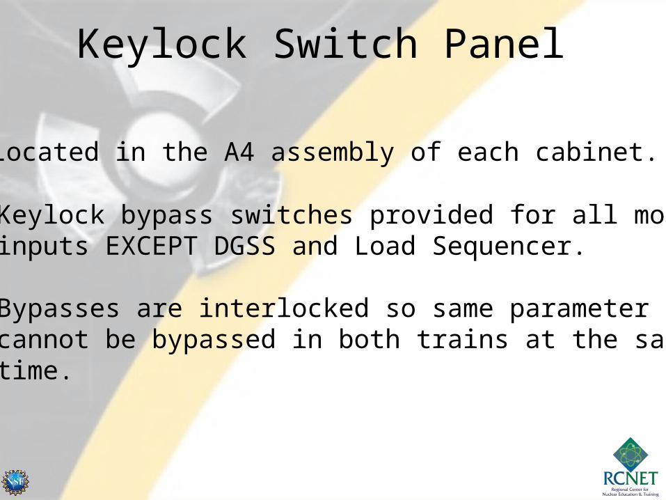
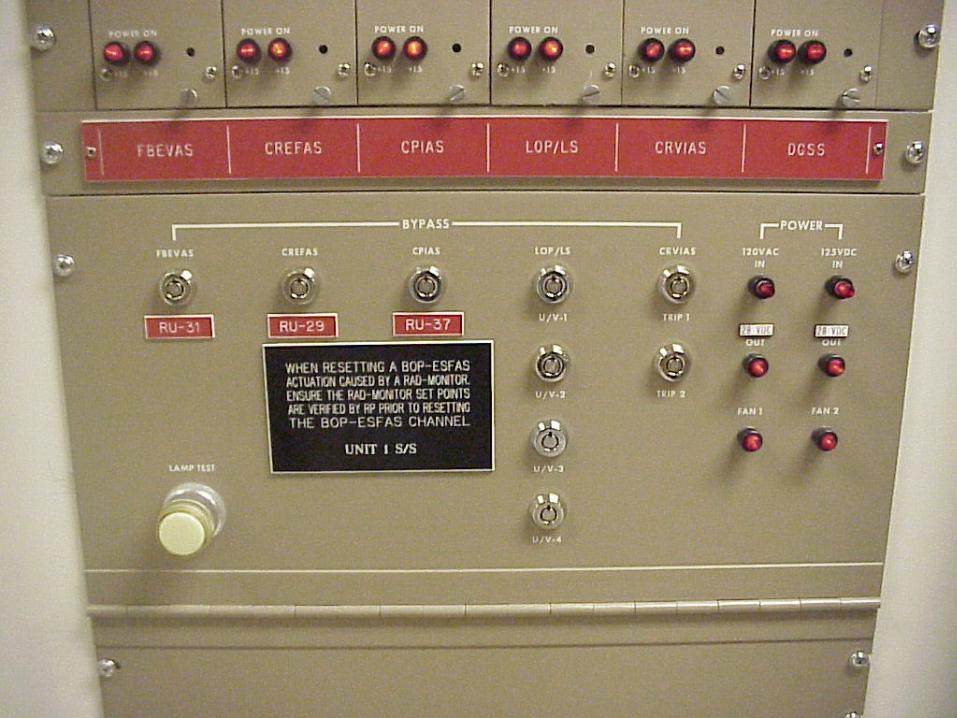
Keylock Switch Panel
• Located in the A4 assembly of each cabinet.
• Keylock bypass switches provided for all module inputs EXCEPT DGSS and Load Sequencer.
• Bypasses are interlocked so same parameter cannot be bypassed in both trains at the same time.

8 8

Isolator Assembly
• Located in the A5 assembly• 18 optical isolators on a single board•Photodiode optically coupled to a phototransistor• Isolate communication between logic trains “A” and “B”
Page 9 of printbook

VTD-G063-00002Example: Page 10 of printbook

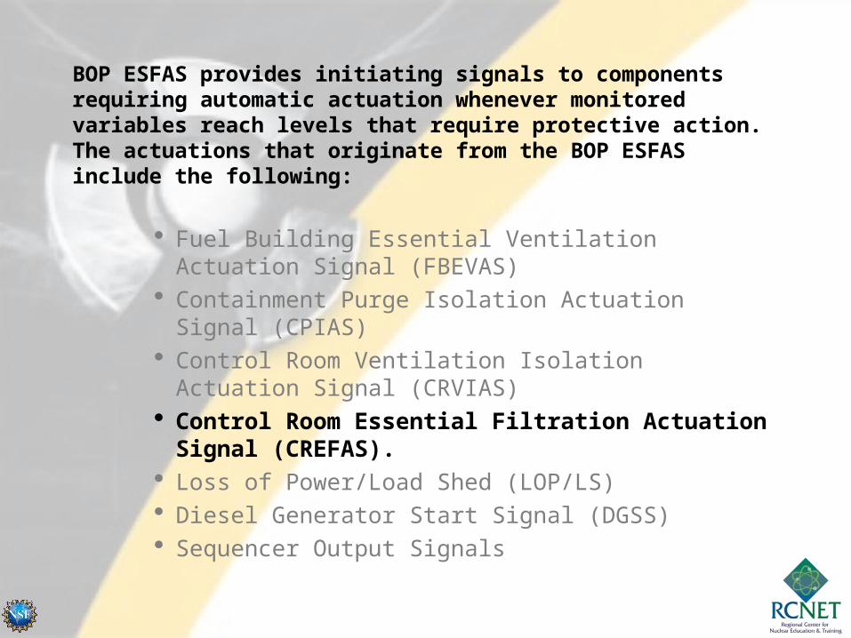
BOP ESFAS provides initiating signals to components requiring automatic actuation whenever monitored variables reach levels that require protective action. The actuations that originate from the BOP ESFAS include the following:
Fuel Building Essential Ventilation Actuation Signal (FBEVAS)
Containment Purge Isolation Actuation Signal (CPIAS) Control Room Ventilation Isolation Actuation Signal
(CRVIAS) Control Room Essential Filtration Actuation Signal
(CREFAS). Loss of Power/Load Shed (LOP/LS) Diesel Generator Start Signal (DGSS) Sequencer Output Signals

Safety System Functions
Fuel Building Essential Ventilation Actuation Signal (FBEVAS):
FBEVAS operates two redundant filter trains whenever 1 of 2 high radiation signals are received and maintains negative pressure in the Fuel Building to prevent leakage of unfiltered air to the environment in the event of a fuel handling accident

Norm Supply…Norm Supply and Exhaust Fans STOP…and Exhaust dampers CLOSE
Essential Exhaust Dampers OPENand Essential AFUs START
These actions cause the Fuel Bldg Essential AFUs to start and take a suction of the Fuel Bldg.What if a SIAS and a FBEVAS occur concurrently?


RU-31 HIGH
Signal entersBOP ESFAS
Signal passesfirst “OR” gate.
Signal is then applied to the “AND” gate.
What does this do?
Signal passessecond “OR”gate.

RU-31 CLEARS
What happens to the signal?
How do I clear it?
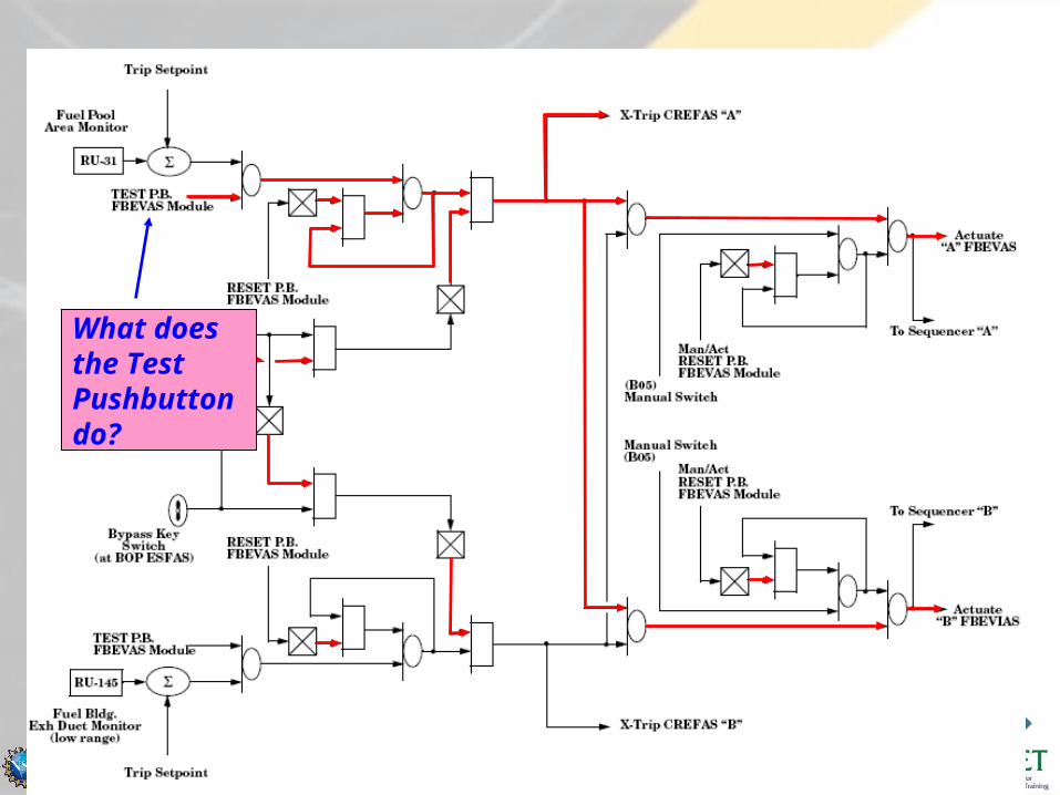
What does the Test Pushbutton do?

This goes away as soon as I release the pushbutton
How do I clear this signal?
I still need to reset at the cabinet

Let’s take a look at the BYPASS.
Now RU-31 alarms
This “AND” Gate blocks the signal from passing

Here is a scenario…
I&C is testing RU-31 with the channel in bypass.
Operations then bypasses RU-145.WHAT HAPPENS?

NOTICE – RU-145 is never bypassed
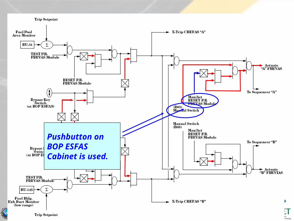
Let’s look at the B05 Controls.
What happens when I take the Channel “A” switch to actuate?
I now release the switch.
Signal is sealed in, just like before. I need to break the seal in to clear.
Pushbutton on BOP ESFAS Cabinet is used.

The system returns to “normal” as I release the pushbutton

Here is the BYPASS Switch


FBEVAS Module

TRIP
RESET
TEST
BYPASS
ACTUATE
MAN RST

EO08 STATE THE FUNCTION AND DESCRIBE THE CONSTRUCTION AND OPERATION OF THE CPIAS MODULECPIAS MODULE, TO INCLUDE INPUTS, OUTPUTS, TEST FEATURES, CONTROLS, AND INDICATIONS.
EO09 STATE THE FUNCTION AND DESCRIBE THE CONSTRUCTION AND OPERATION OF THE CREFAS MODULECREFAS MODULE, TO INCLUDE INPUTS, OUTPUTS, TEST FEATURES, CONTROLS, AND INDICATIONS.
BALANCE OF PLANT ENGINEERED SAFETY BALANCE OF PLANT ENGINEERED SAFETY FEATURE ACTUATION SYSTEMFEATURE ACTUATION SYSTEM

BOP ESFAS provides initiating signals to components requiring automatic actuation whenever monitored variables reach levels that require protective action. The actuations that originate from the BOP ESFAS include the following:
Fuel Building Essential Ventilation Actuation Signal (FBEVAS)
Containment Purge Isolation Actuation Signal (CPIAS)
Control Room Ventilation Isolation Actuation Signal (CRVIAS)
Control Room Essential Filtration Actuation Signal (CREFAS).
Loss of Power/Load Shed (LOP/LS) Diesel Generator Start Signal (DGSS) Sequencer Output Signals

Safety System Functions
Containment Purge Isolation Actuation Signal (CPIAS):
CPIAS stops either a Power Access or Refueling Purge by closing inlets and outlets in the event of 1 of 2 high radiation signals. It thus minimizes offsite dose in event of a fuel handling accident in containment

Refuel Purge Upstream UV-2A/2B CLOSERefuel Purge Downstream UV-3A/3B CLOSEAccess Purge Upstream UV-4A/4B CLOSEAccess Purge Downstream UV-5A/5B CLOSE
The Purge Supply and Exhaust Fans are interlocked with their respective containment isolation dampers causing these fans to trip when the dampers isolate.These actions will also occur upon a CIAS.

WHAT’S DIFFERENT?

Tech Spec 3.3.8 CPIAS
• One CPIAS shall be operable
• During modes 1-4, core alts or fuel movement in containment
• If not, shut down and close containment purge
• Minimizes offsite dose in event of a fuel handling accident in containment
BOP ESFAS provides initiating signals to components requiring automatic actuation whenever monitored variables reach levels that require protective action. The actuations that originate from the BOP ESFAS include the following:
Fuel Building Essential Ventilation Actuation Signal (FBEVAS)
Containment Purge Isolation Actuation Signal (CPIAS) Control Room Ventilation Isolation Actuation Signal
(CRVIAS) Control Room Essential Filtration Actuation Signal
(CREFAS). Loss of Power/Load Shed (LOP/LS) Diesel Generator Start Signal (DGSS) Sequencer Output Signals
Safety System Functions
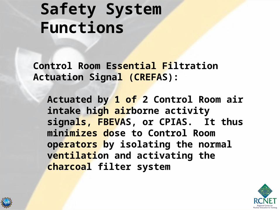
Control Room Essential Filtration Actuation Signal (CREFAS):
Actuated by 1 of 2 Control Room air intake high airborne activity signals, FBEVAS, or CPIAS. It thus minimizes dose to Control Room operators by isolating the normal ventilation and activating the charcoal filter system

HJA-M02HJB-M02
HJA-M03HJB-M03
HJA-M01HJB-M01
HJA-M52HJB-M55
HJA-M59HJB-M13
HJA-M58HJB-M10

HJA-M58HJB-M10
HJA-M59HJB-M13
HJA-M02HJB-M02
HJA-M03HJB-M03
HJA-M52HJB-M55 HJA-M01
HJB-M01

WHAT’S DIFFERENT?
These inputs are coming into the circuit

Tech Spec 3.3.9 CREFAS
• One CREFAS shall be operable
• During modes 1-6 and during fuel movement
• Or place one CREFS in operation

BALANCE OF PLANT ENGINEERED SAFETY BALANCE OF PLANT ENGINEERED SAFETY FEATURE ACTUATION SYSTEMFEATURE ACTUATION SYSTEM
EO10 STATE THE FUNCTION AND DESCRIBE THE CONSTRUCTION AND OPERATION OF THE CRVIAS MODULECRVIAS MODULE, TO INCLUDE INPUTS, OUTPUTS, TEST FEATURES, CONTROLS, AND INDICATIONS.
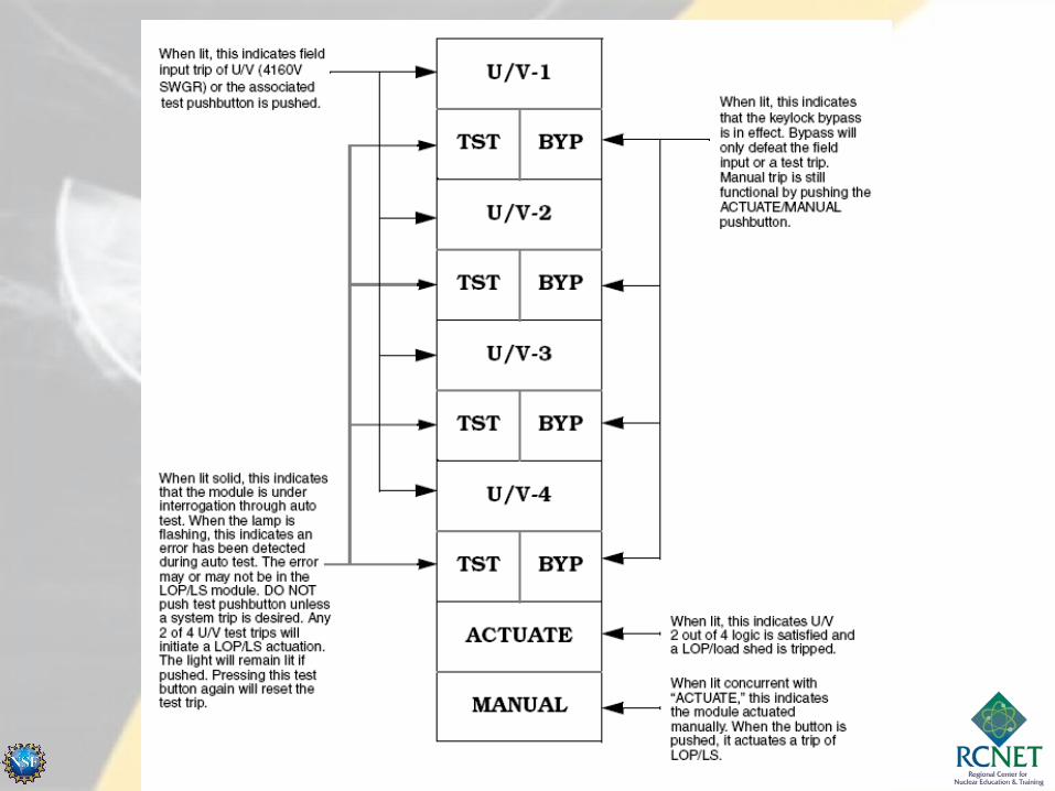
EO11 STATE THE FUNCTION AND DESCRIBE THE CONSTRUCTION AND OPERATION OF THE LOP/LS MODULELOP/LS MODULE, TO INCLUDE INPUTS, OUTPUTS, TEST FEATURES, CONTROLS, AND INDICATIONS.

BOP ESFAS provides initiating signals to components requiring automatic actuation whenever monitored variables reach levels that require protective action. The actuations that originate from the BOP ESFAS include the following:
Fuel Building Essential Ventilation Actuation Signal (FBEVAS)
Containment Purge Isolation Actuation Signal (CPIAS)
Control Room Ventilation Isolation Actuation Signal (CRVIAS)
Control Room Essential Filtration Actuation Signal (CREFAS).
Loss of Power/Load Shed (LOP/LS) Diesel Generator Start Signal (DGSS) Sequencer Output Signals

Safety System Functions
Control Room Ventilation Isolation Actuation Signal (CRVIAS):
CRVIAS is actuated manually by Control Room operators upon smoke alarm from outside air intake plenum. The chlorine detector automatic actuation is deleted. This signal isolates the normal and ENGINEERED ventilation for the Control Room

This looks very different, but at a closer look…System was set up for two inputs (each having 2 trains)


CRVIAS Module

What happens on a CRVIAS?
Normal Ventilation Dampers CLOSE, CR Ess AHU A and B Outside Air Intake Dampers CLOSE, Condensate Transfer Pump A and B STARTS, CR Ess AHU Fans START, Essential Cooling Water START, Spray Pond pumps START, Essential Chillers START.
CRVIAS will override the Outside Air Damper Open signal from SIAS or CREFAS. The damper will be closed by the CRVIAS.

HJA-M58HJB-M10
HJA-M59HJB-M13
HJA-M02HJB-M02
HJA-M03HJB-M03
HJA-M52HJB-M55 HJA-M01
HJB-M01
Dampers CLOSE

BOP ESFAS provides initiating signals to components requiring automatic actuation whenever monitored variables reach levels that require protective action. The actuations that originate from the BOP ESFAS include the following:
Fuel Building Essential Ventilation Actuation Signal (FBEVAS)
Containment Purge Isolation Actuation Signal (CPIAS) Control Room Ventilation Isolation Actuation Signal
(CRVIAS) Control Room Essential Filtration Actuation Signal
(CREFAS). Loss of Power/Load Shed (LOP/LS) Diesel Generator Start Signal (DGSS) Sequencer Output Signals

Safety System Functions
Loss of Power/ Load Shed (LOP/LS):
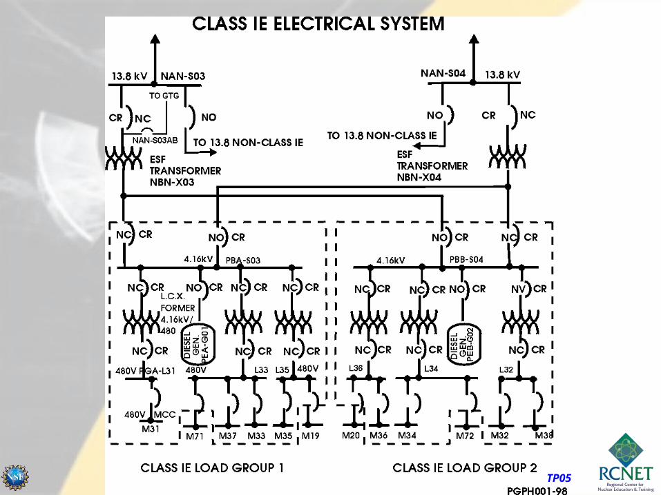
LOP/LS is actuated by 2 of 4 undervoltage relays on 4.16 KV bus. The 1 second Load Shed pulse causes a shed of the 4.16 KV loads and selected 480 V loads and opens 4.16 KV preferred offsite supply breakers. The 60 second off-delay LOP actuates forced shutdown loads


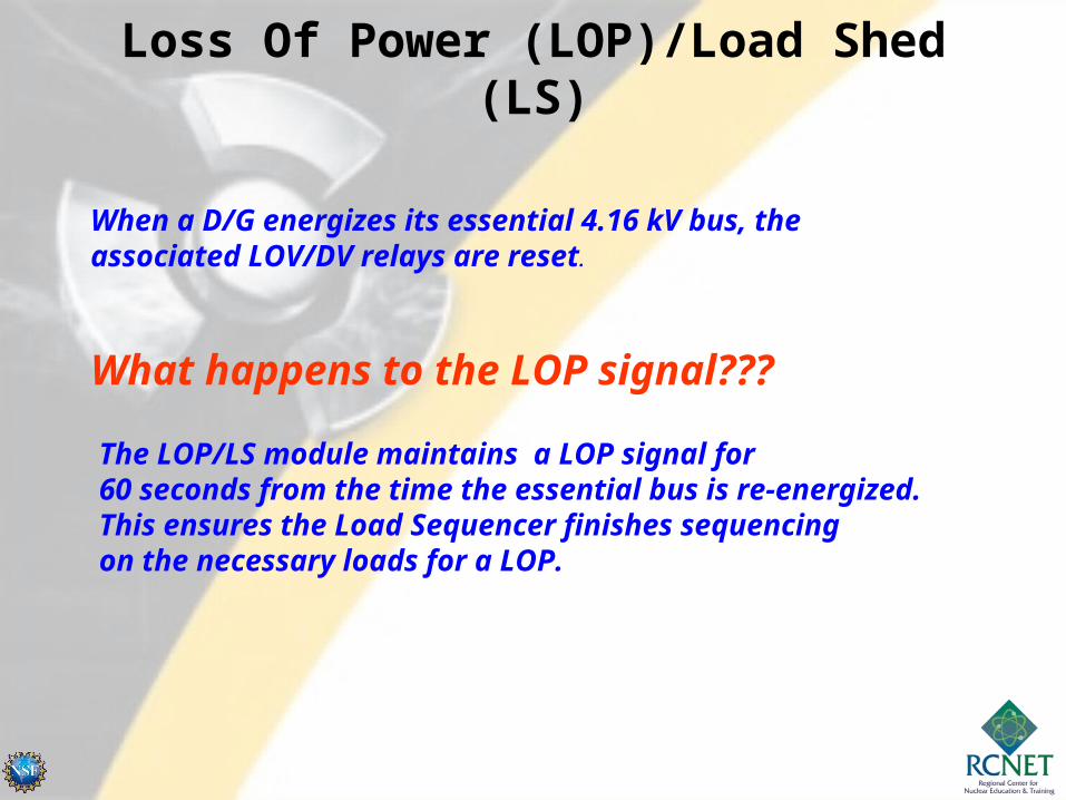
Loss Of Power (LOP)/Load Shed (LS)
Degraded Voltage
DegradedVoltageRelay
DegradedVoltageRelay
DegradedVoltageRelay
DegradedVoltageRelay
4 solid state degraded voltage relays monitor PBA-S03 and PBB-S04.2 of the 4 channels sense degraded voltage condition… trip signal sent to the DGSS module.
Relay set at approximately 89% to 91% of normal voltage.
PBA-S03
Relays need power to operate! Receive 125 Vdc from PKA (PKB)
Loss Of Power (LOP)/Load Shed (LS)
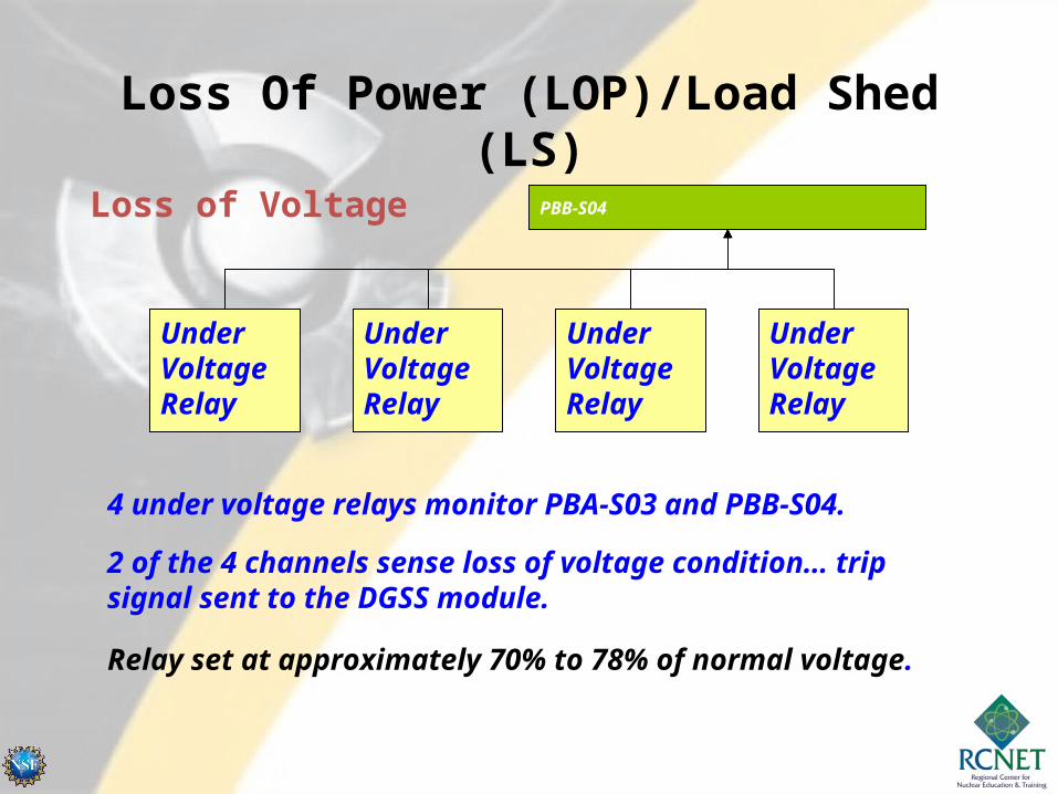
Loss of Voltage
UnderVoltageRelay
UnderVoltageRelay
UnderVoltageRelay
UnderVoltageRelay
4 under voltage relays monitor PBA-S03 and PBB-S04.
2 of the 4 channels sense loss of voltage condition… trip signal sent to the DGSS module.
Relay set at approximately 70% to 78% of normal voltage.
PBB-S04

Loss Of Power (LOP)/Load Shed (LS)
Here is a way to look at the Tech Spec setpoints...
4160 Vac0 Vac
3697 Vac
3786 Vac
Degraded
2929.5 Vac
LOV
Relay must actuatebetween 28.6 and 35seconds
Relay must actuatebetween 10.3 and 12.6seconds at 2929.5 Vac...
Degraded Voltage time delay is NOT impacted byvoltage level!
Loss of Voltage time delay IS! The lower thevoltage level, theshorter the time delay!
Relay must actuatebetween 2.0 and 2.4seconds at 0 Vac...

Loss Of Power (LOP)/Load Shed (LS)
What is so bad about degraded voltage?
4160 Vac
480 Vac480 Vac Load
LOW VOLTAGE
What can wesay about thepower to thisload?


Loss Of Power (LOP)/Load Shed (LS)
What happens on an actuation?
LOP/LS module sends the LOP signal to the DGSS module and also initiates load shed actuation.
A 1 second load shed pulse is sent to selected loads to trip them as part of the load shed scheme.
The DGSS module will start the Emergency Diesel Generator which will close in and energize the associated essential 4.16 kV bus.
The DG Output Breaker closes automatically based on the LOP
Loss Of Power (LOP)/Load Shed (LS)
When a D/G energizes its essential 4.16 kV bus, the associated LOV/DV relays are reset.
What happens to the LOP signal???
The LOP/LS module maintains a LOP signal for 60 seconds from the time the essential bus is re-energized. This ensures the Load Sequencer finishes sequencing on the necessary loads for a LOP.
TP05

EO12 STATE THE FUNCTION AND DESCRIBE THE CONSTRUCTION AND OPERATION OF THE DGSS MODULEDGSS MODULE, TO INCLUDE INPUTS, OUTPUTS, TEST FEATURES, CONTROLS, AND INDICATIONS.
EO13 STATE THE FUNCTIONS AND DESCRIBE THE CONSTRUCTION AND OPERATION OF THE LOAD LOAD SEQUENCER/AUTO TEST MODULESEQUENCER/AUTO TEST MODULE, TO INCLUDE INPUTS, OUTPUTS, TEST FEATURES, CONTROLS, AND INDICATIONS.
BALANCE OF PLANT ENGINEERED SAFETY BALANCE OF PLANT ENGINEERED SAFETY FEATURE ACTUATION SYSTEMFEATURE ACTUATION SYSTEM

BOP ESFAS provides initiating signals to components requiring automatic actuation whenever monitored variables reach levels that require protective action. The actuations that originate from the BOP ESFAS include the following:
Fuel Building Essential Ventilation Actuation Signal (FBEVAS)
Containment Purge Isolation Actuation Signal (CPIAS) Control Room Ventilation Isolation Actuation Signal
(CRVIAS) Control Room Essential Filtration Actuation Signal
(CREFAS). Loss of Power/Load Shed (LOP/LS) Diesel Generator Start Signal (DGSS) Sequencer Output Signals

Safety System Functions
Diesel Generator Start Signal (DGSS):
Actuated by AFAS-1 or AFAS-2, SIAS/CSAS, or LOP signals, the
DGSS starts the Diesel Generator and the DG Exhaust System


DGSS sendsstart signal toDiesel GeneratorSIAS signalAFAS-1 and AFAS-2LOP
Diesel status iscommunicated back to the Load Sequencer


3.3.7 Diesel Generator (DG) - Loss of Voltage Start (LOVS)

BOP ESFAS provides initiating signals to components requiring automatic actuation whenever monitored variables reach levels that require protective action. The actuations that originate from the BOP ESFAS include the following:
Fuel Building Essential Ventilation Actuation Signal (FBEVAS)
Containment Purge Isolation Actuation Signal (CPIAS) Control Room Ventilation Isolation Actuation Signal
(CRVIAS) Control Room Essential Filtration Actuation Signal
(CREFAS). Loss of Power/Load Shed (LOP/LS) Diesel Generator Start Signal (DGSS) Sequencer Output Signals

Safety System FunctionsLoad Sequencer/Auto Test:
The Load Sequence is actuated by:• LOP • SIAS• CSAS• AFAS• DG run • CREFAS, CRVIAS, or FBEVAS
It generates sequential timed start and permissive signals to ESF and forced shutdown system fans, pumps, and chillers. It does not operate valves or dampers. It auto tests each module every 22 seconds when in Auto Test

ESF Load Sequencer
What does it do for us?• Receives a number of inputs and based on
these inputs, decides which mode of operation to place BOP ESFAS in.
• The mode of operation will determine what equipment is started.

ESF Load Sequencer
• Devices which are sequentially actuated through the Load Sequencer receive a load shed signal on bus under-voltage to trip the device load...and a load sequencer start signal to start the device at the appropriate time.
• Reset of the Load Sequencer and its actuation relays does not stop or shed actuated devices.

ESF Load Sequencer
• Devices are shed only on the load shed signal.
• If LOP is input, sequencer sends signals back to LOP/LS module. These signals are a 1 second load shed pulse and a 60 second off-delay LOP drive. (Keeps LOP signal active for 60 seconds after the D/G has re-energized the bus.)

MODE 0No inputStandby Operation
MODE 1SIAS/CSAS(No LOP)
MODE 2SIAS/CSAS/LOPDG Bkr Closed
MODE 3LOP OnlyDG Bkr Closed
MODE 4Everything else
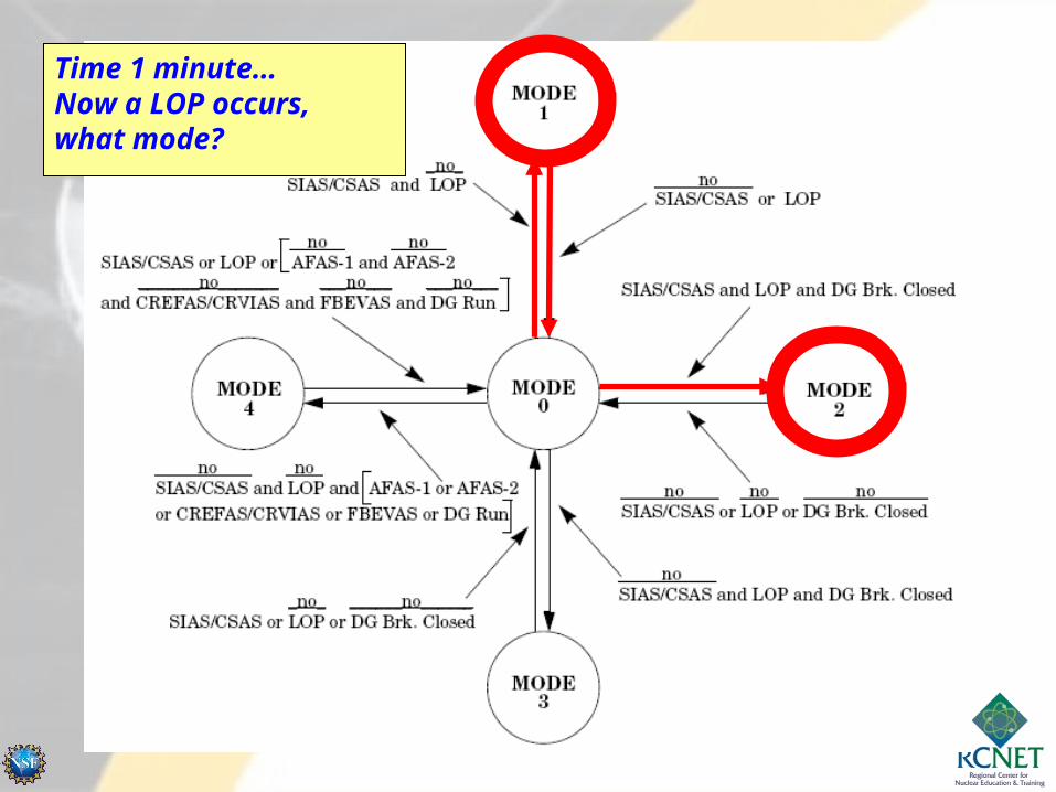
Time 0…SIAS occurs, what mode?Time 1 minute…Now a LOP occurs,what mode?

Does it stay in Mode 2?

SIAS is reset… what happens?

You take the DG off the bus. What mode?
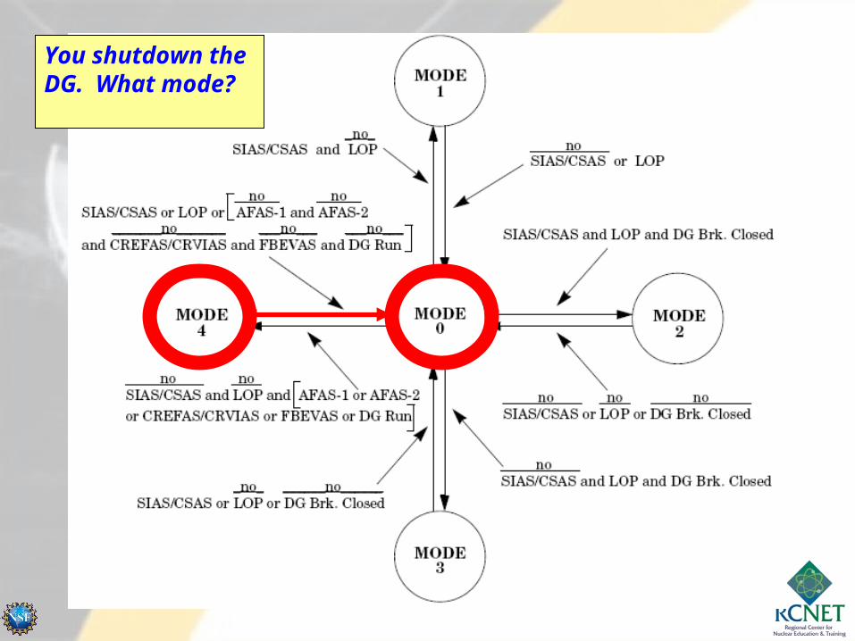
You shutdown the DG. What mode?


HPSI PUMP START
LPSI PUMP START
DIESEL GEN. ESS. EXHAUST FAN START
CONTROL ROOM ESS. AHU START
FUEL BLDG ESS. EXHAUST AFU START
AUX FEEDWATER PUMP START
CONTAINMENT SPRAY PUMP START
ESS. COOLING WATER PUMP START
ESS. SPRAY POND PUMP START
ESS. CHILLER PUMP START
CHARGING PUMP START PERM. (UNBLOCKED)
0 5 10 15 20 25 30 40 50 60TIME (SECONDS)
MODE 1 TIMING DIAGRAM: SIAS CSAS LOP DG BKR
0
5
5
25
5
10
15
20
25
30
40
5FUEL BLDG ESS. EXHAUST AFU START

HPSI PUMP START
LPSI PUMP START
DIESEL GEN. ESS. EXHAUST FAN START
CONTROL ROOM ESS. AHU START
BATTERY CHARGER START
FUEL BLDG ESS. EXHAUST AFU START
AUX FEEDWATER PUMP START
CONTAINMENT SPRAY PUMP START
ESS. COOLING WATER PUMP START
ESS. SPRAY POND PUMP START
ESS. CHILLER PUMP START
CHARGING PUMP START PERM.
0 5 10 15 20 25 30 40 50 60TIME (SECONDS)
MODE 2 TIMING DIAGRAM: SIAS CSAS LOP DG BKR
0.5
5
5
5
5
10
15
20
25
30
40
0.5480 LOAD CENTER
5
DIESEL GEN. ESS. EXHAUST FAN START
CONTROL ROOM ESS. AHU START
BATTERY CHARGER START
AUX FEEDWATER PUMP START
ESS. COOLING WATER PUMP START
ESS. SPRAY POND PUMP START
ESS. CHILLER PUMP START
0 5 10 15 20 25 30 40 50 60TIME (SECONDS)
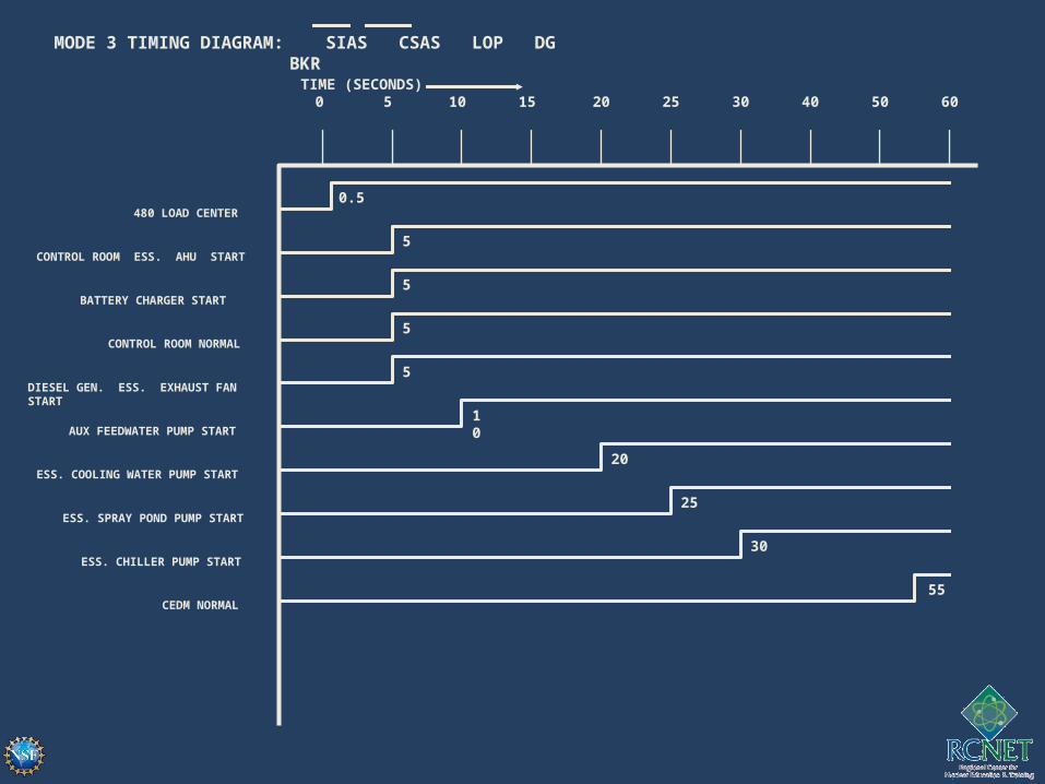
MODE 3 TIMING DIAGRAM: SIAS CSAS LOP DG BKR
0.5
5
5
5
10
20
25
30
480 LOAD CENTER
CONTROL ROOM NORMAL
CEDM NORMAL55
5

CONTROL ROOM ESS. AHU START
AUX FEEDWATER PUMP START
ESS. COOLING WATER PUMP START
ESS. SPRAY POND PUMP START
ESS. CHILLER PUMP START
0 5 10 15 20 25 30 40 50 60TIME (SECONDS)
MODE 4A TIMING DIAGRAM: SIAS CSAS LOP (AFAS-1 OR AFAS-2)
5
20
25
30
0
0 5 10 15 20 25 30 40 50 60TIME (SECONDS)
20
25
30
ESS. COOLING WATER PUMP START
ESS. SPRAY POND PUMP START
ESS. CHILLER PUMP START
MODE 4B TIMING DIAGRAM: SIAS CSAS LOP (CREFAS OR CRVIAS)

0 5 10 15 20 25 30 40 50 60TIME (SECONDS)
DIESEL GEN. ESS. EXHAUST FAN START5
0 5 10 15 20 25 30 40 50 60TIME (SECONDS)
25ESS. SPRAY POND PUMP
0Fuel Bldg Ess. Exhaust AFU
MODE 4C TIMING DIAGRAM: SIAS CSAS LOP (FBEVAS)
MODE 4D TIMING DIAGRAM: SIAS CSAS LOP (DG RUN)

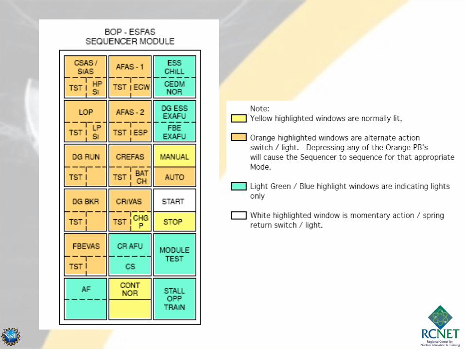
Sequencer Testing
• Sequencer polls each module in BOP ESFAS cabinet one at a time by sending a pulse to the module.
• The module then processes the test input and sends a return signal to the sequencer.

Sequencer Testing
• If the sequencer does not receive the proper test return signal, auto test stops and the affected module’s "TEST" light will flash.
• The other train will indicate a stall in the opposite train and cause the “STALL OPPOSITE TRAIN” annunciator to alarm.
BOP ESFASTEMP HIPWR SPLY/AUTO TESTFAIL
EO14 Describe the use of Prevent Event Tools and Electrical Safe Work Practices to minimize human performance errors during testing or maintenance of the BOP ESFAS.
EO15 Given examples of BOP ESFAS maintenance problems, determine the fault using applicable BOP ESFAS prints, Tech Manuals, and applicable documents.
BALANCE OF PLANT ENGINEERED SAFETY BALANCE OF PLANT ENGINEERED SAFETY FEATURE ACTUATION SYSTEMFEATURE ACTUATION SYSTEM


Troubleshooting Scenario #1
You are at the step to bypass CPIAS Train “A” in accordance with the BOP ESFAS functional test (36MT-9SA01).
You turn the key clockwise ¼ turn at the CPIAS Train “A” module, the BYPASS annunciator on the module is lit. You check the control room and observe the plant annunciator window 5A03D (BOP ESFAS CH BYP) is not lit.
What actions do you take?What could be the problem?

Troubleshooting Scenario #2
Plant is Mode 1, 100% power. A “HI CR RAD CH TRIP” (Window 5A04C) is received in the control room (CR) and Train “B” CREFAS module has both TRIP and ACTUATE annunciators lit.
The following occurs:-CR Ess AHU damper opens (M-HJB-M02)-CR Normal AHU isolation dampers close-Comm equipment isolation dampers close-CR Ess isolation dampers close-CR toilet and kitchen exhaust isolation dampers close- OPS reports that the Condensate Transfer Pump did not start and the M-HJB-M03 damper did not open.- Cross train “A” CREFAS was actuated.
What actions do you take?What could be the problem?


END