planning framework - updated 021512
TRANSCRIPT

ILLIANA CORRIDOR PLANNING FRAMEWORK TECHNICAL DOCUMENTATION
Planning Framework Technical Documentation
DRAFT Technical Memorandum
Illiana Corridor Study
Prepared for
Illinois Department of Transportation and
Indiana Department of Transportation
February 15, 2012
ILLIANA CORRIDOR PLANNING FRAMEWORK TECHNICAL DOCUMENTATION
ILLIANA CORRIDOR PAGE 2
Table of Contents
1.0 INTRODUCTION ........................................................................................................... 3
2.0 PROJECT BACKGROUND ........................................................................................... 4
3.0 CORRIDOR DEVELOPMENT ..................................................................................... 6
4.0 FIRST ROUND SCREENING ....................................................................................... 7
5.0 SECOND ROUND SCREENING ............................................................................... 10
6.0 FINALIST BUILD .......................................................................................................... 10
7.0 GEOMETRIC AND ALIGNMENT GUIDELINES ................................................. 10
8.0 HIGHWAY GEOMETRICS ......................................................................................... 13
9.0 ACCESS CONTROL ..................................................................................................... 16
10.0 DESIGN EXCEPTIONS................................................................................................ 16
Exhibits
Exhibit 1 Illiana Study Area ........................................................................................................ 4 Exhibit 2 Corridor Widths ........................................................................................................... 6 Exhibit 3 Corridor Naming Convention.................................................................................... 7
Appendix
Freeway Design Criteria Tables ................................................................................................... i Freeway Typical Sections ............................................................................................................ ii
ILLIANA CORRIDOR PLANNING FRAMEWORK TECHNICAL DOCUMENTATION
ILLIANA CORRIDOR PAGE 3
1.0 Introduction
The Illiana Corridor Phase I Study Alternatives Development and Evaluation Planning Framework will be used by the project team as a reference throughout the course of the study. It will document the design standards and constraints for the Illiana Corridor study alignments and features. The Planning Framework will be considered a “living document,” as it is expected that the Planning Framework will be updated, as needed, in order to accommodate the ongoing progression of detailing the alternatives for the project. The project goals will be related to the items described in the Planning Framework. Any deviation from the criteria or required variances will be included as part of the Planning Framework. The recommended policies and guidelines incorporated into this document are governed by the following industry manuals and regulations:
• Illinois Department of Transportation Bureau of Design and Environment Manual, 2011 (BDE)
• Indiana Department of Transportation Design Manual (IDM), 2011
• Illinois Bureau of Local Roads & Streets Manual, 2005
• American Association of State Highway and Transportation Officials, 2004 (AASHTO)
• Manual on Uniform Traffic Control Devices, 2009 (MUTCD)
• Illinois Supplement to the National Manual on Uniform Traffic Control Devices, 2009
• Indiana Manual on Uniform Traffic Control Devices, 2008
• Federal Highway Authority (FHWA) “Flexibility in Highway Design”
• Illinois Department of Transportation (IDOT) “Highway Standards”
• Illinois Department of Transportation (IDOT) “Land Acquisition Manual”, 2011
• Illinois Department of Transportation (IDOT) “Survey Manual”, 2001
• Illinois Department of Transportation (IDOT) “Drainage Manual”
• IDOT Context Sensitive Design
• American Association of State Highway and Transportation Officials “Roadside Design Guide”
• Indiana Department of Transportation “Geotechnical Manual”, Revised 2010
• Transportation Research Board, “Highway Capacity Manual”, 2000 and 2011

ILLIANA CORRIDOR PLANNING FRAMEWORK TECHNICAL DOCUMENTATION
ILLIANA CORRIDOR PAGE 4
2.0 Project Background
The Illinois Department of Transportation (IDOT), the Indiana Department of Transportation (INDOT) and the Federal Highway Administration (FHWA) are evaluating the transportation system in an area that traverses Will County and northern Kankakee County in Illinois and southern Lake County in Indiana. This comprises a study area of approximately 950 square miles that is generally located between I‐65 on the east, I‐55 on the west, and bordered by U.S. 30 to the north (Exhibit 1).
Previous studies have indicated possible benefits from the development of an east‐west transportation corridor extending from I‐55 in Illinois to I‐65 in Indiana. These include providing an alternate route for motorists traveling the I‐90/94 corridor, relieving traffic on the I‐80 Borman/Kingery Expressway and U.S. 30, serving as a bypass for trucks around the congested metropolitan highways, providing access to one of the largest “inland port” intermodal freight areas in the U.S. and the proposed South Suburban Airport, supporting economic development in this area, and the potential for substantial job creation. Will County, Illinois was one of the fastest growing counties in the U.S. between 2000 and 2010, adding 175,000 residents and increasing demand for additional transportation options.
Exhibit 1 Illiana Study Area
In accordance with 23 CFR Part 771.111, FHWA, IDOT, and INDOT have agreed to conduct the Illiana Corridor study as a Tiered Environmental Impact Statement (EIS). The Tier One EIS includes an examination of the overall transportation system improvement needs, a study of alternatives to satisfy them, and broad consideration of potential environmental and social impacts of the possible alternatives. The Tier One evaluation is completed at a sufficient level of engineering and environmental detail to assist decision makers in selecting a preferred transportation system alternative(s). Tier
ILLIANA CORRIDOR PLANNING FRAMEWORK TECHNICAL DOCUMENTATION
ILLIANA CORRIDOR PAGE 5
One includes preparing a draft and final EIS that will disclose potential environmental and social effects (evaluated at a planning level) of the proposed improvements. The final EIS will conclude with a Record of Decision (ROD) by FHWA that states the preferred transportation system alternatives to be carried forward into Tier Two.
It is expected that the Illiana Corridor Tier I planning and engineering approach will be followed as indicated below.
• Corridor Development ‐ through one‐on‐one meetings with project stakeholders, the transportation problems of the study area will be identified and an appropriate range of improvement strategies will be developed at a conceptual level. Multiple corridor alignments (2,000 ft wide footprint with a 400 ft wide working alignment) will be generated and an inventory of socio‐economic and environmental resources within each corridor’s working alignment will be made to assess the probability of impacts within the corridor for relative comparison of corridors. This process will identify up to 15 corridors that will be evaluated in the First Round Screening
• First Round Screening – The initial set of 15 alternatives, developed as part of the Corridor Development process, will be pared down to five alternatives during the First Round Screening. The First Round Screening will first consider how well each alternative meets the project’s Purpose and Need, addresses the 2040 travel demands of the study area, and avoid cultural and environmental impacts. In addition, a qualitative screening for financial feasibility will be conducted to determine the relative attractiveness of the alternatives to the private sector and the potential for value creation. Corridor alternatives with obvious and significant negative social, economic, or environmental impacts will be eliminated from consideration. The remaining corridor alternatives will then be sufficiently defined to the extent that travel performance modeling can be conducted. No more than five (5) corridor alternatives will be carried forward into the Second Round Screenings.
• Second Round Screening – During the second round screening, the five (5) remaining transportation system corridor alternatives will be developed to a functional layout level of detail to permit an initial assessment of engineering viability, potential environmental issues, and relative planning level costs with the objectives of minimizing potential significant impacts and of identifying the best performing alternatives to be carried forward as Finalist Build Alternatives. It is anticipated that no more than two (2) Finalist Build Alternatives will be advanced.
• Finalist Build Alternatives – Finalist Build Alternative(s) will be carried forward and fully evaluated in the Environmental Consequences Chapter of the Tier One DEIS.

ILLIANA CORRIDOR PLANNING FRAMEWORK TECHNICAL DOCUMENTATION
ILLIANA CORRIDOR PAGE 6
• Draft EIS and Engineering Studies – provide environmental and engineering work regarding draft EIS documentation.
3.0 Corridor Development
As part of Tier I, the project will identify, define, and evaluate a wide range of transportation alternatives that address the study Purpose and Need statement. Based on stakeholder input and technical analysis, corridors will be identified and defined that are approximately 2,000 feet in width that connect I‐65 on the east with I‐55 to the west. Each of the identified corridors will contain one or more “working alignments” that will range in width from approximately 400 feet to 600 feet based on socio‐economic and environmental considerations. See Exhibit 2. These corridors will be developed using information collected from the GIS database as a guide to seek to avoid or minimize the potential for impacts to wetlands, streams, historic sites, residential areas, commercial areas, landmarks, and other environmental features. This process will identify up to 15 corridors that will be evaluated in the First Round Screening.
Exhibit 2 Corridor Widths

ILLIANA CORRIDOR PLANNING FRAMEWORK TECHNICAL DOCUMENTATION
ILLIANA CORRIDOR PAGE 7
The corridor naming convention can be seen in Exhibit 3. These corridors are labeled based on the location where they intersect I‐55 and I‐65. For I‐55, going from north to south, corridors will be labeled with an “A”, “B”, etc. For I‐65, going from north to south, they are labeled ”1”, “2”, etc. Thus, Corridor “A1” would extend from location “A” on I‐55 to location “1” on I‐65. If there are variations within a corridor, a designation of “n” for north, or “s” for south, with a variation number will be used.
Exhibit 3 Corridor Naming Convention
4.0 First Round Screening
First Round Screening, will begin by taking the initial set of 15 transportation system corridor alternatives developed as part of the Corridor Development process and comparing each of these alternatives to determine how well each meet’s the project’s Purpose and Need. Any alternatives that fail to meet the project’s Purpose and Need will be dropped from consideration.
The transportation system corridor alternatives will then be sufficiently defined such that transportation performance modeling can be conducted to determine how well each of the remaining alternatives can meet the 2040 travel demands of the study area. These initial transportation alternatives will be evaluated using the 2040 CMAP (Chicago Metropolitan Agency for Planning) regional travel forecasting model to evaluate transportation performance. This travel model will assist in determining the alternatives with the best transportation performance. To conduct this level of modeling, the logical termini, working alignment, number of lanes (if a highway facility), number of and
ILLIANA CORRIDOR PLANNING FRAMEWORK TECHNICAL DOCUMENTATION
ILLIANA CORRIDOR PAGE 8
location of stations (if multi‐modal, rail, or transit), and access needs, including location and type will need to be defined.
Transportation performance criteria will be developed to screen the alternatives based on the Purpose and Need for the project. A range of acceptable performance within those measures will be defined. Identifying this range of acceptable performance will allow for a comparison between alternatives to determine which alternatives best meet the Purpose and Need for the project. The selected evaluation measures will be applied to the alternatives and the results compared to the No Build Alternative.
It is anticipated that the following general types of evaluation measures will be used.
• Traffic Volumes (By vehicle type, i.e. passenger cars, commercial vehicles)
• Vehicle Miles and Hours of Travel (Use of facilities by vehicle type and by functional classification (freeways, arterials, local roads, etc.)
• Level of Service and/or Volume‐Capacity Ratio
• Vehicle Hours of Delay (Free Flow Travel Time versus Actual Travel Time)
• Congested Vehicle Miles of Travel (Portion of travel occurring under congested conditions)
• Accessibility to Jobs
• Mode Split and Auto Diversions
• Freight Tonnage
• Crashes (by functional classification)
• Toll Revenue
Once the transportation system corridor alternatives have been defined and travel performance modeling conducted, the project team will utilize the GIS database to identify any cultural or environmental impacts within the identified corridors including:
• Impacts to wildlife habitat, water resources, threatened and endangered species, and public lands.
• Impacts to cultural resources.
• Impacts to farmland.
• Impacts to low‐income and minority populations defined by census tracts bordering the proposed alternatives.
• Impacts to the transportation network, based on results from travel modeling.
• Air, noise, and energy impacts based upon changes in travel patterns.

ILLIANA
The iareascorridimpathe co
The fscreeattraccreatialternsectopotendetai
Corrienviralternand l. The tproce
A CORRIDOR
dentifications will cause tdor will be sacts to a pre‐orridor alter
final step to bning for finactiveness of ion. Specificnatives and tr partner. Antial for the pl.
idor alternatronmental imnatives will tlocation of al
transportatioess, which w
n of any signthe corridor scored baseddetermined rnatives mee
be conducteancial feasibeach alternac consideratithe extent toAdditionally,private secto
tives with obmpacts will bthen be preslternatives
on performawill assist in d
nificant impaalternative td upon their range of accets the identi
ed in the Firsility analysiative to the pion will be go which thos, the potentior funding fo
bvious and sbe eliminatesented for sta
ance and footdetermining
PLANNING F
acts in any oto be droppelevel of impceptable valuified criteria
st Round Scrs. This willprivate sectogiven to the rse risks couldial for generaor a portion
significant nd from consakeholder in
tprint evalug the best alt
FRAMEWORK T
of these cultued from furtpacts, compaues to determa.
reening will l help determor and the porisk profile od be shared ating revenuof the proje
egative sociasideration. Rnput and add
ation approaternatives to
ILLIATECHNICAL DO
ural or envirther consideraring their lemine how w
be a qualitamine the relaotential for vof the variouwith a potenue through tect will be ex
al, economicRemaining cditions relat
ach will be acarry forwa
ANA CORRIDOOCUMENTATIO
PAGE
ronmental ration. Eachevel of well each of
ative ative value us ntial privatetolls, and thexamined in
c, or orridor tive to mode
an iterative ard.
OR ON
E 9
h
e e
e

ILLIANA CORRIDOR PLANNING FRAMEWORK TECHNICAL DOCUMENTATION
ILLIANA CORRIDOR PAGE 10
5.0 Second Round Screening
The Second Round Screening will take the alternatives advanced through First Round Screening and develop them to a functional layout level of detail to permit an initial assessment of engineering viability, potential environmental issues, and relative planning level costs with the objective of identifying the best performing alternatives to be carried forward as Finalist Build Alternatives. The corridor alternatives will be compared to determine which corridors best meet the project’s Purpose and Need, address the transportation problems that exist in the study area, as identified by project stakeholders, are financially feasible to construct and operate, as well as which corridor alternatives meet the other screening criteria as defined by the project stakeholders.
Typical cross sections and corresponding ROW widths will be developed and expanded into a corridor “footprint”. These corridor footprints will be used to measure impacts with the GIS database. Accordingly, the corridor alternatives will be developed to a sufficient level of detail to assess relative impacts for each corridor alternative. This step includes refinement to the corridor location (termini and corridor), development of working alignments, development of conceptual interchange layouts, identification of potential transit station locations, and conceptual station layout as necessary to distinguish between alternatives.
6.0 Finalist Build
Successive levels of refinement, stakeholder input and evaluation will be applied until the Finalist Build Alternatives are identified and evaluated.
The remaining corridor alternatives will be further evaluated by conducting travel performance modeling to determine how well each alternative meets the transportation performance measures. Transportation performance measures such as LOS, volume to capacity (v/c) ratios, vehicle miles of travel (VMT), travel time savings (TTS), and safety will be used to assess the ability of the strategies to alleviate the identified transportation problems, and to illustrate performance differences. This travel demand modeling evaluation will help identify the optimal combinations of corridor alternatives to be carried forward as part of the Finalist Build Alternatives.
7.0 Geometric and Alignment Guidelines
Alignment studies will be provided for those corridors that the traffic modeling produces feasible results. Cross‐road interchanges will first be established, along with ramp and access control limits.

ILLIANA CORRIDOR PLANNING FRAMEWORK TECHNICAL DOCUMENTATION
ILLIANA CORRIDOR PAGE 11
System interchanges will initially be located at the following interstates: I‐65 I‐57 I‐55 Service interchange concepts will be initially located at state routes including, but not limited to the following: IL 53 US 45/52 IL 50 IL 1 IL 394 US 41 IN 55 Non‐interchange cross‐roads to remain open will be preliminary determined based upon traffic data and local agency coordination. Where a cross‐road will remain open, assume cross‐road over freeway. For relocation/displacement assessment assume road will shift to favor one side of crossroad and assume displacements/impacts on the other. The following is a list of other Locational Geometric and Alignment Guidelines: • Freeway/Tollway mainline design speed – 70 mph
• Freeway/Tollway mainline – IDOT desirable horizontal radius 3000 ft or greater, minimum 2040 ft radius
• Cross streams/floodplains at 90 degrees or as practical
• Parallel electrical transmission towers and pipe lines where practical or cross perpendicular. At transmission towers, cross at 90 degrees near tower to maximize vertical clearance to electrical cables.
Basic guidelines for Alignment Development are described below: If large wooded areas (5 acres or more) cannot be avoided due to other resource impacts, the alignment should skirt the wooded area and other adjacent land‐use, if feasible. Alignments in farmland areas should parallel property lines to the extent possible to minimize farm severance management zones and land locking parcels.
ILLIANA CORRIDOR PLANNING FRAMEWORK TECHNICAL DOCUMENTATION
ILLIANA CORRIDOR PAGE 12
Alignments in proximity to existing or planned subdivisions, where they cannot be avoided due to reducing impacts on a higher order impact, should be located along the outside edge or along the first row of the subdivision/development. No new construction of any highway, public road, or any part of the interstate system, whether Federal, State, or local, shall be permitted through or across any portion of the Midewin National Tallgrass Prairie, per federal law (P.L 104‐106 of 1996, Section 2915). During this phase of alignment studies, impacts generally cannot be explicitly ranked relative to avoidance, since neither the quality of the natural resource nor the indirect and cumulative impacts of the specific alignment will be known. However, for the sake of providing some guidance, the following sensitive socio‐economic and environmental issue areas are provided:
• INAI site or natural area, 6(f), etc
• T & E Federal or State
• CERCLIS/RCRA Site/Landfills
• Longitudinal floodplain encroachment
• Wetland Impacts
• Parks/Recreational Area (Public)
• Historic Structures (Building/Bridge) Historic District relocations/proximity impacts
• Cemeteries
• Residential, Commercial, Industrial, Public, Farm Displacement
• Planned Developments Platted/Permit
• Developments Planned no Permit/Platt
• Quarries
ILLIANA CORRIDOR PLANNING FRAMEWORK TECHNICAL DOCUMENTATION
ILLIANA CORRIDOR PAGE 13
8.0 Highway Geometrics
The Highway Geometrics criteria will adhere to the latest IDOT BDE and INDOT IDM requirements, unless otherwise specified. The criteria will be utilized during the Finalist Build Corridor Analysis, which consists of evaluating up to 2 corridors alignments after their horizontal and vertical features are further developed. The criteria may also be used for earlier portions of the project study. Criteria tables per functional classification have been developed. The following highway and geometric criteria will be followed throughout the development of the corridor alternatives: Functional Classification The application of road design criteria depends on various highway system classifications that have been developed, especially the functional classification system. All highways in the corridor study shall be split amongst the following categories (See Chapter 43 of BDE and Chapter 40 of IDM):
• Urban and Rural Categories and Subcategories
• Functional Classification System
• Highway Jurisdictions
Design Speed Design speed is selected for each facility, which will establish criteria for several geometric design elements, including horizontal and vertical curvature, superelevation rates, cross sectional features, and sight distances. In general, the selected design speed is based on the following road design elements:
• Functional Classification
• Terrain
• Traffic Volumes
(For selected Design Speeds see attached appendixes) Design Vehicle The Design Vehicle Type for the Corridor Study is based on Functional Classification using BDE Manual, Chapter 36 and IDM Chapter 40.

ILLIANA CORRIDOR PLANNING FRAMEWORK TECHNICAL DOCUMENTATION
ILLIANA CORRIDOR PAGE 14
Design Forecast Year Design years are recommended in Chapter 31 of BDE and Chapter 40 of IDM. For the Illiana Corridor Study, designers will be using a 2040 Design Year. Horizontal Alignment Chapter 32 of the BDE Manual indicates IDOT criteria for horizontal alignment elements and Chapter 43 of the IDM Manual indicates INDOT criteria for horizontal alignment elements, such as curvature, superelevation, and sight distance. It has an application of several functional classes of highway. In addition, consideration should be given to adhere to certain design principles and controls, which will determine the overall safety and aesthetic appearance of the facility. These design principles include: • Usage of minimum radii should be avoided if practical, especially in level terrain. • Avoid using compound and Broken‐Back Curves. • Alignments should be properly coordinated to minimize environmental impacts.
(For minimum and desirable values of horizontal alignment components, such as radii, length of curve and maximum Superelavation rates see attached appendixes) Vertical Alignment
Chapter 33 of BDE Manual indicates IDOT guidance on vertical alignment elements and Chapter 44 of the IDM indicates INDOT guidance on vertical alignment elements, which contribute significantly to the highway’s safety, aesthetics, operations, and costs. These elements include maximum and minimum grades, vertical curvature, vertical clearances, critical lengths of grades and aesthetics. (For minimum and desirable values of vertical alignments components, such as maximum and minimum grades, K ‐ values for crest and sag curves see attached appendixes) Horizontal and Vertical Alignment Coordination Horizontal alignments should be coordinated with vertical alignment, and location of potential interchanges, bridges, and other existing and/or proposed features. Appropriate combinations of vertical and horizontal alignment should consider the following guidelines:
• Curvature and grades should be in proper balance. • Sharp horizontal curvature should not be introduced at or near the top of a
pronounced crest vertical curve or at the bottom of a steep grade approaching or near the low point of a pronounced sag vertical curve.
• Changes in profile and alignment should generally coincide with one another.
ILLIANA CORRIDOR PLANNING FRAMEWORK TECHNICAL DOCUMENTATION
ILLIANA CORRIDOR PAGE 15
Sight Distance
Chapter 31 of the BDE Manual and Chapter 42 of the IDM provide criteria for such important elements of the design process, such as: • Stopping Sight Distance • Decision Sight Distance • Passing Sight Distance • Intersection Sight Distance (For minimum values of various types of sight distances see attached appendixes)
Horizontal Clearance Chapter 38 of the BDE Manual and Chapter 49 of the IDM indicate IDOT and INDOT applications of roadside safety measures. These are based on type of roadways and provide clear zone distances, which provide a recovery area for errant vehicles that run off the roadway. It also provides criteria for the use of roadside barriers, median barriers, and impact attenuators where providing the clear zone is not practical. It also discusses the use of cost‐effective methodologies to determine roadside safety treatments. (For Clear Zone values see attached appendixes) Vertical Clearance Chapter 39 of the BDE Manual and Chapter 44 of the IDM indicate IDOT and INDOT design criteria for vertical clearances for under passing roadways based on functional classification and rural/urban location. (For Vertical Clearance values see attached appendixes) Typical Section Elements
Chapter 34 of BDE Manual and Chapter 45 of the IDM provides guidance to consider certain cross section elements, including lane and shoulder width, cross slopes, type and width of medians, side slopes, right‐of way and utilities. It also discusses roadside elements such as sidewalks and roadway ditches. Typical Cross Sections, which represent the study’s Freeway, Arterial, Collector, and Local roadways, is included in the attached appendixes.

ILLIANA CORRIDOR PLANNING FRAMEWORK TECHNICAL DOCUMENTATION
ILLIANA CORRIDOR PAGE 16
9.0 Access Control
Chapter 35 of the BDE Manual and Chapter 86 of the IDM discusses the general concepts of access management, describes common access management techniques, and presents detailed figures on providing access control criteria for interchange crossroads. Additional information on access control is described in BDE Chapters 37, 44‐46.
The IDOT publication “Policy on Permits for Access Driveways to State Highways” discusses procedures for obtaining access to non‐access controlled State Highways, and describes the design requirements for driveways and entrances in conjunction with individual permits. (For Access Control see attached appendixes)
10.0 Design Exceptions
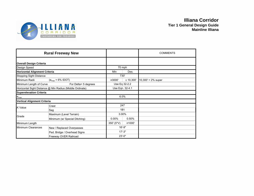
Overall Design CriteriaDesign SpeedHorizontal Alignment Criteria Min Des.Stopping Sight DistanceMinimum Radii (emax = 6% IDOT) ≥3000' ≥ 10,300' 10,300' = 2% superMinimum Length of Curve For Delta< 5 degreesHorizontal Sight Distance @ Min Radius (Middle Ordinate)Superelevation Criteriaemax
Vertical Alignment Criteria
CrestS
Illiana CorridorTier 1 General Design Guide
Mainline Illiana
Rural Freeway New COMMENTS
730'
Use Eq 32-2.2
70 mph
6.0%
Use Eqn. 32-4.1
181K Value
247
SagMaximum (Level Terrain)
Minimum (w/ Special Ditching) 0.00% 0.50%
Minimum Length 350' (5*V) ≥1000'Minimum Clearances New / Replaced Overpasses
Ped. Bridge / Overhead Signs Freeway OVER Railroad
181
Grade3.00%
17'-3"23'-0"
16'-9"
