planning folder wastewater
TRANSCRIPT
PLANNING FOLDER WASTEWATER Positive displacement blower, rotary lobe compressor and turbo blower.
Performance³. For plant manufactures, engineering offices and operators.
TECHNOLOGIES BY AERZEN. MORE THAN 150 YEARS OF EXPERIENCE.
Expect Performance.
The story of AERZEN? It is the story of compressor techno-
logy. In 1868, we built the first positive displacement blower
in Europe. In 1911, we were the first to build turbo blowers in
the world. Then, in 1943, the first for screw type compressors,
and in 2010, the first rotary lobe compressor worldwide. And
today? Today, it is our task to design these machines to work
as efficiently as possible - and to adapt them to the hundreds
of applications our customers bring to us.
What remains? We have preserved the character of a medi-
um-sized family company into the fourth generation. This
gives us the drive to be innovative. And to develop products
which support our customers significantly in their global mar-
kets. Expect a lot. Expect Performance!
Typical for AERZEN.
What distinguishes modern premium technologies? Perfor-
mance and worldwide service? Of course. Energy efficiency?
Nowadays, this goes without saying. However, we, at AER-
ZEN, believe there is more to it than that. More ideas, for ex-
ample. These are evident in many national and international
patents.
But at AERZEN, these can also be found in more discreet as-
pects of our machines. In the particularly compact design. In
our simple Plug&Play principle. In their fantastic comfortab-
le operating concepts. Or think about the unusually long oil
change and maintenance intervals. This brings us back to the
topic of quality. The unconditional reliability, the extremely
long service life of our technology paired with ground-brea-
king energy efficiency - all of this is typical for AERZEN.
2

CONTENTS
AERZEN AND WASTEWATER TECHNOLOGY Wastewater treatment plant schematics
Application reports
PLANNING FOUNDATIONS Calculation of operating data
Pressure and temperature fluctuations
Notes about machine room design and pipework routing
POSITIVE DISPLACEMENT BLOWER DELTA BLOWER Technology
Standard scope of supply
Performance specification
Maintenance and revision
Technical drawings
ROTARY LOBE COMPRESSOR DELTA
HYBRID Technology
Standard scope of supply
Performance specification
Maintenance and revision
Technical drawings
TURBO BLOWER AERZEN TURBO Technology
Standard scope of supply
Performance specification
Maintenance and revision
Technical drawings
PERFORMANCE³ - EFFICIENT COMBINATION SOLUTIONS
ACCESSORIES
Power cabinet and frequency converter
Silencer
SERVICE Tender specifications
Wear parts and maintenance contracts
RENTAL SERVICE
AERZEN WORLDWIDE
4
6
8
10
12
13
16
18
20
24
28
30
66
68
72
76
84
86
108
110
114
118
124
126
136
138
142
144
146
148
150
152
Planmap ABWA – EN – 00 – 12.2015
3

AERZEN AND WASTEWATER TECHNOLOGY.
Industrialisation is spreading ever further. Even Third World countries are no longer exempt from
this. In the established industrial nations of this world, the extent of mechanisation has reached a
point at which nature alone is no longer able to compensate the strains associated with technology.
Key topics such as global warming and lowering of the groundwater table dominate newspaper
headlines and are subject of discussions amongst people. The call to sustain our environment is
becoming louder and louder.
The procedure
There are many options to apply methods to avoid da-
maging the environment. In the case of wastewater
e.g. the ventilation of the sediment tank or the pressu-
re ventilation of biological wastewater treatment sys-
tems. The oxygen introduction is important, for deep
wastewater tanks, wastewater treatment systems with
standard aeration tanks or natural clarification ponds alike.
If the wastewater has already entered the natural cycle,
ventilating lakes and rivers prevents additional contami-
nation. When treating drinking water, rinsing the filters
with compressed air ensures that perfect water is provi-
ded and natural water reserves are not used excessively.
Gas which occurs on landfill sites, digestion towers or gas
which is produced when treating wastewater does not es-
cape into the environment anymore or is not just burned.
Blower for sediment tank Delta Blower
Mechanical stage
Computer Sediment tank Oil and grease collector Primary wastewater tank
Wastewater
Excess sludge
Sludge
Digester
gas
Biogas blower Delta Blower
4
Gas tank Digestion tower

It is used sustainably to create energy to relieve the en-
vironment and remedy resource deficits. Due to the
pressure increase of biogas blowers, the gas is trans-
ported to CHPs or generators where the converted ener-
gy can be used to heat buildings or greenhouses, for
subsequent pneumatic transport of the dried sludge. AERZEN
products not only do their job in the examples given above. Just
as there are many options to protect the environment, there
are many areas of application for AERZEN positive displace-
ment blowers, rotary lobe compressors and turbo blowers.
example. The produced gas is measured by AERZEN ro-
tary piston gas meters. During sludge drying processes,
AERZEN positive displacement blowers can be used for the
Delta Blower / Delta Hybrid / Aerzen Turbo
for stimulating the biology
mechanically
cleaned
wastewater
Aeration tank
Wastewater
with activated
sludge
Secondary wastewater tank
cleaned
wastewater
Return sludge
Activated sludge
Delta Blower
Sludge drying for pneumatic transportation
5

APPLICATION REPORTS.
WASTEWATER TREATMENT PLANT ARNSBERG WILDSHAUSEN
New AERZEN turbo blower improves performance and efficiency.
Background: cost-intensive old plant
The Ruhrverband Essen operates a biological wastewater
treatment plant designed for 98,000 p.e. in Arnsberg -
Wildshausen. It cleans the wastewater of 48,000 people
and also the wastewater of a paper mill. This mill supplies
between 3,000 and 6,000 m3 wastewater every day which
is pre-treated anaerobically in two IC-reactors (IC = Internal
circulation). The entire flow in the wastewater treatment
plant fluctuates between 210 and 1,070 l /s depending on
the day of the week, time of day and the weather. The plant
operates with an activated sludge procedure. The wastewater
first flows past two counterflow screens. Then, sand and
other minerals are collected in two parallel sand collector
chambers. Finally, it is aerated in three consecutive aeration
tanks. The air required for this is generated in the central
air station in the basement of the press building. Three
nineteen-year-old turbo compressors were in operation there
until November 2012. They were connected in series and were
operated according to the load-dependent air requirements
of the three aeration tanks. The paper mill pre-treated its
wastewater and therefore, only a maximum of two turbo
blowers were required to generate the air necessary for the
aeration process. This anaerobic pre-treatment transforms
the carbon contained in the wastewater mainly into methane.
The exhaust air contaminated with hydrogen sulphide is
sucked off by an AERZEN positive displacement blower of
the Delta Blower series which is attached to the aeration
tank. It is then pushed into the aeration tank. This means
that the carbon filter previously used for cleaning the exhaust
air is no longer required. Costs associated with this are saved.
Furthermore, the odour around the aeration tank improved
significantly.
Problem: Wear and high cost
One of the three old turbo systems already showed
significant wear in 2012. Rather than going through extensive
and expensive revisional work, this old plant was going to be
replaced by a new turbo compressor.
Segment
Problem
Solution
Result
Company
Contact
Environmental technology
High maintenance and energy costs
Aerzen Turbo Generation 5
Significant energy saving, reduction
of maintenance and ancillary costs,
improvement of supply reliability.
Aerzener Maschinenfabrik GmbH
Reherweg 28 - 31855 Aerzen
Germany
Phone: +49 5154 81-0
Fax: +49 5154 81-9191
www.aerzener.de
Sebastian Meißler
Phone: +49 5154 81 9970
Fax: +49 5154 81 71 9970

This was done to also improve the energy efficiency of the
station and to increase the supply reliability in the aeration
tanks.
The performance of the turbo blower is then lowered so that
both systems can operate in parallel. If the target value in the
tank is reached again, the old system switches off and the
Generation 5 takes over by itself.
„Our turbo blower from the Aerzen Turbo Generation 5 series
saves up to 6 % energy, reduces maintenance and ancillary
costs, improves supply reliability and means that the expen-
sive general overhaul of the old system is no longer necessary.“
Markus Droppelmann,
Group manager Ruhrverband Essen
The solution: AERZEN Turbo Generation 5
Markus Droppelmann, group manager Obere Ruhr for the
Ruhrverband in Essen, saw the new turbo blower “Aerzen Tur-
bo Generation 5” for the first time when he visited the IFAT in
Munich in May 2012. The performance data of one system of
this new design was almost identical to those of the system
which needed replacing. Droppelmann reports: “A detailed
profitability calculation revealed that this exchange would
actually save 5 to 6 % energy. That means that the exchange
would redeem itself after five to eight years just considering
the ongoing energy costs.” Furthermore, the design-related
problem of oil storage for lubrication and cooling purposes
does not occur with the new system. “This means we did
not only avoid the cost for the due general maintenance of
a nineteen-year-old machine with a new system. We could
also lower our energy costs, save CO2 within the group and
increase the supply reliability of our wastewater treatment
plant, “ the group manager explains the decision.
The change: New turbo blower as base load system
Peter Knippers prefers to use the new system as the base
load system. A second system from the old plant is added
as a peak load system for only five hours a day. “As soon as
the prescribed oxygen target value in the tank drops the new
turbo blower kicks in, which then increases the output by in-
creasing the speed, “ he explains. If the system has reached
its upper performance limit, the old system is switched on.
The company
The Aerzener Maschinenfabrik GmbH was founded in 1864 and
is a world-leading supplier of twin-shaft positive displacement
machines and turbo machines. The product range includes
rotary lobe compressors, positive displacement blowers, turbo
blowers, screw compressors and gas meters. The Aerzener
Maschinenfabrik employs around 1,800 employees and has
more than 40 international subsidiaries. Aerzen’s innovative
The result: Powerful and efficient
AERZEN is an experienced application specialist and offers
positive displacement blowers and turbo blowers from one
place. The new turbo blower design AT Turbo Generation 5
was designed for high intake volume flows and sets a new
example in wastewater treatment. The speed-regulated
state-of-the-art turbo machines which work oil-free offer
significant advantages for wastewater treatment, particu-
larly regarding performance strength and efficiency.
Advantages AERZEN Turbo Generation 5:
· Maximised performance and energy efficient for high
volume flows
· Low service life costs
· High-tech components with long service life
· Low maintenance and service effort
· Low sound level
technology solutions benefit from the experience gained from
more than 150 years in business. Worldwide, industrial plants
are supplied with gaseous media using AERZEN blowers,
compressors, turbos and gas meters. Apart from standard
products, the company also offers customised solutions.
Furthermore, Aerzen offers a comprehensive range of After-
Sales services - from repairs to upgrades of existing systems
and to condition monitoring.
AERZEN SERVICE
Correct service to secure and increase energy efficiency of biological wastewater treatment plants.
Background: Energy and cost efficiency for biological
wastewater treatment plants
Every biological wastewater treatment plant requires a com-
pressed air station to supply the oxygen for the aeration tank.
This only operates with maximum energy efficiency, if it is
not possible that the downstream system increases the sys-
tem pressure, insufficient ventilation does not cause exces-
sive suction temperatures and/or insufficient maintenance
does not lead to increased operating time. Practical examples
show that these criteria influence the energy efficiency of a
blower negatively and lead to a significant increase in energy
costs.
„Practical examples show that a pressure increase of, for ex-
ample, 50 mbar can lead to an increased energy consumption
of five to ten percent depending on the design of the blower.
This can lead to several thousands of Euros in extra costs. (...)“
Frank Glöckner, After-Sales-Service
Segment
Problem
Service
Increased pressure, high room tem-
peratures and insufficient mainte-
nance lead to high cost
Example: Increased system pressure caused by the down-
stream system
Every blower is set to a pre-defined pressure before leaving
the factory. The air compressed to this pressure is then led
to vents distributed throughout the tank via ring line with
several stub lines. Diaphragm control valves which are cor-
rectly operated at the inlet of the tank are a precondition for
the optimal operation. Incorrectly set valves quickly lead to
increased pressure in the supply network, the blowers must
operate against increased pressure and the energy costs in-
crease. Furthermore, the diaphragm control valves are con-
trolled via pressure stabilization. This means, the supply
lines are automatically closed when the required oxygen level
is reached. The blowers which are often frequency-regulated
are shut down in a time-lagged manner after the valve is
closed. If this delay (waiting period) is set too long, the blow-
ers have to operate against closed or partially closed valves in
full load. This has the effect that air escapes via the pressure
valves. This does not only lead to air loss. In extreme cases, an
increased counter pressure can also damage the blower pack-
aged units. The counter pressure can also increase when the
diffusers in the tank have aged due to chemical compounds
Solution
Result
Company
Contact
Correct and comprehensive service
Increase of energy efficiency and
reduction of cost
Aerzener Maschinenfabrik GmbH
Reherweg 28 - 31855 Aerzen
Germany
Phone: +49 5154 81-0
Fax: +49 5154 81-9191
www.aerzener.de
Sebastian Meißler
Phone: +49 5154 81 9970
Fax: +49 5154 81 71 9970
in the wastewater. This is also possible when pipelines and/
or diffusers have become blocked over time because pressure
silencers of the pressure creators are cladded with adsorp-
tion material which has come loose over time and then en-
tered the system via the network. This danger does not occur
with AERZEN positive displacement blowers which were built
after 1995 and with AERZEN rotary lobe compressors of the
new Delta Hybrid range. The foundation of these systems is
a pulsation silencer and a reduction in noise is achieved by
diverting air and not by using adsorption material.
Example: Excessive intake temperature
The air used for compression and cooling a blower is often
taken directly from the installation location and not supplied
via air inlet channels for biological wastewater treatment
plants. This means that the room temperature has a signifi-
cant impact on the energy balance of the system. The room
temperature increases when the ventilation openings are po-
sitioned incorrectly and/or are too small, if the air supply is
not supported by fans which are controlled via thermostats or
if their performance is not sufficient, if the roof of the com-
pressor room is not sufficiently insulated against intensive
sun radiation or if the compressed air supply lines within the
station are not or not sufficiently insulated. The increase of
room temperature also leads to an increased compressed air
temperature and thus, leads to reduced oxygen levels of the
compressed air, a worse filling level and to inferior cooling
of the blowers. All of these criteria have one consequence:
The compressed air generator has to work longer to produce
the required amount of oxygen. As a rule of thumb, you can
say that a temperature reduction of 3°C saves 1% of energy.
This is a reason why AERZEN blowers always suck in air on
the “cold” side of the packaged unit and not on the discharge
side with the pipe connection, as on this side there is a higher
amount of radiated heat.
The company
The Aerzener Maschinenfabrik GmbH was founded in 1864 and
is a world-leading supplier of twin-shaft positive displacement
machines and turbo machines. The product range includes
rotary lobe compressors, positive displacement blowers, turbo
blowers, screw compressors and gas meters. The Aerzener
Maschinenfabrik employs around 1,800 employees and has
more than 40 international subsidiaries. Aerzen’s innovative
Example: Insufficient maintenance
If the system is not maintained as instructed by the manu-
facturer, this can also have a negative effect on the energy
balance. Classic examples are pressure valves damaged by
resistances which are too high or an air filter which was ex-
changed too late. If this air filter is not exchanged for exam-
ple, to save 50 Euros, and only removed and blown out, the
energy requirements of the blower increase. As a general
guideline: A reduction of pressure on the suction side by 10
mbar reduces the energy costs by approx. 1%. For example,
a new filter reduces the pressure by approx. 5 mbar, dirty fil-
ters, however, drop the pressure by 30 mbar.
Conclusion
Increasing energy costs can be avoided if all blowers are main-
tained and serviced by the service departments of the manu-
facturer and/or the operator. After all, the energy costs of a
compressor - when considering its long service life - make up
almost 90% of the system‘s entire cost. Only approx. 10% are
spent on investment and maintenance costs.
technology solutions benefit from the experience gained from
more than 150 years in business. Worldwide, industrial plants
are supplied with gaseous media using AERZEN blowers,
compressors, turbos and gas meters. Apart from standard
products, the company also offers customised solutions.
Furthermore, Aerzen offers a comprehensive range of After-
Sales services - from repairs to upgrades of existing systems
and to condition monitoring.

_
PLANNING FOUNDATIONS.
Technical and design features and the changing air requirements in aeration tanks challenge the
ventilation technology of every wastewater treatment plant. The demand for energy efficiency and
the reduction of operating costs are particularly important. However, the most important criterion
when planning wastewater treatment plants is still the highest level of reliability and availability.
The iron principle of engineering “each chain is only as strong as its weakest link” still applies.
That is why we would like to give some basic information about the machine design, room design
and pipework routing.
Calculation of operating data
Standard state (physical)
The standard state of a gas
refers to the pressure pNabs = 1,01325 bar
at the temperature TN = 273 K - ^0°C
e.g. volume flow in standard state QN [mN3/h]
density in standard state ρN [kg/m3] relation between Celsius temperature t[°C]
Suction state
The blowers/compressors are constructed in the suction sta-
te, i.e. at the actual pressure in the inlet socket p1abs[bar] at
the average or maximum temperature of the
gas in the inlet socket t1[°C] or T1=TN+T1[K]. For the suction
of atmospheric air aim for the average abs. suction pressure
p1abs = 1.0 bar suction temperature t1 = 20°C or T1 = 293K
T=TN+ t [K] and the thermodynamic temperature T[K]
Impact of installation height
The atmospheric pressure p1abs decreases as the height of the installation location increases:
mNN
P1abs[bar]
mNN
P1abs[bar]
mNN
P1abs[bar]
mNN
P1abs[bar]
0 1,031
100
200
300
400
500
600
700
800
900
1000
1,001
0.989
0,977
0,967
0,955
0,944
0,932
0,921
0,909
0,899
1100
1200
1300
1400
1500
1600
1700
1800
1900
2000
0,888
0,877
0,867
0,856
0,845
0,835
0,824
0,815
0,805
0,795
2100
2200
2300
2400
2500
2600
2700
2800
2900
3000
0,785
0,776
0,765
0,756
0,747
0,737
0,728
0,719
0,709
0,701
3100
3200
3300
3400
3500
3600
3700
3800
3900
4000
0,692
0,684
0,675
0,667
0,657
0,649
0,641
0,632
0,624
0,616
Calculation of volume flow Q from prescribed mass flow
1.
For the standard state:
with mass flow in [kg/h] Density ρ in [kg/m3]
10
2. For the suction state:

in state:
3 dry
s. chart partial the
33
Density ρn of gases in standard state and specific heat capacity cp
Air
Natural gas
Town gas
Landfill gas
Nitrogen
Hydrogen
ρn [kg/m3]
Cp [kJ/kgK]
1,293
1,005
0,96
1,926
0,61
2,227
1,21
1,314
1,25
1,038
0,09
14,051
Calculation of intake volume flow Q1 from prescribed
standard volume flow QN
1. Dry gas
2. Humid gas
PNabs abs. = Pressure in standard state in [bar]
p1abs abs. = Pressure in suction state in [bar]
T1 = Temperature in suction state in [K]
TN = Temperature im Normzustand: TN= 273 K
QN = Standard volume flow in [mN3 /h], trocken = Humidity, cp = RF 1 00 [ II ]]
The conversion according to equation (1) for transport and
compression of atmospheric air (relative humidity on average
60% and installation height up to 500 mNN) is sufficiently
exact!
Calculation of density „“1 in suction state 1. Dry gas
2.
Humid gas
Density „“1 in suction state of atmospheric air p1abs = 1,0 bar
RF
PS
ρN
ρs
= relative humidity in [%]
= Partial pressure of steam in [bar],
seeTable Partial pressure ofof steam,
saturation state
= Density in standard state in [kg/m ]]
= Density of steam in [kg/m3]
Intake temperature [°C]
Density ρ1 in [kg/m3]
-20
1,377
-10
1,325
0
1,276
5
1,253
10
1,231
15
1,210
20
1,19
30
1,15
40
1,113
Partial pressure of steam, saturation state
-20 -18
-16
-14
-12
-10
-8
-6
-4
-2
0
1
2
3
4
5
6
7
8
9
10
11
t [°C]
Ps [bar]
0,001029
0,001247
0,001504
0,001809
0,002169
0,002594
0,003094
0,003681
0,004368
0,005172
0,006108
0,006566
0,007055
0,007575
0,008129
0,008781
0,009345
0,010012
0,010720
0,011472
0,012270
0,013116
ρs [kg/m3]
0,000881
0,001059
0,001267
0,001513
0,001800
0,002136
0,002529
0,002986
0,003517
0,004133
0,004847
0,005192
0,005588
0,005946
0,006358
0,006795
0,007258
0,007748
0,008267
0,008816
0,009396
0,01001
13 14
15
16
17
18
19
20
21
22
23
24
25
26
27
28
29
30
32
34
36
38
t [°C]
Ps [bar]
0,014965
0,015973
0,017039
0,018168
0,019362
0,02062
0,02196
0,02337
0,02485
0,02642
0,02808
0,02982
0,03166
0,03360
0,03564
0,03778
0,04004
0,04241
0,04753
0,05318
0,05940
0,06624
ρs [kg/m3]
0,01134
0,01206
0,01282
0,01363
0,01447
0,01536
0,01630
0,01729
0,01833
0,01942
0,02057
0,02177
0,02304
0,02437
0,02576
0,02723
0,02876
0,03037
0,03382
0,03759
0,04172
0,04624
42 44
46
48
50
52
54
56
58
60
62
64
66
68
70
72
74
76
78
80
90
100
t [°C]
Ps [bar]
0,08198
0,09100
0,10086
0,11162
0,12335
0,13613
0,15002
0,16511
0,18147
0,1992
0,2184
0,2391
0,2615
0,2856
0,3116
0,3396
0,3696
0,4019
0,4365
0,4736
0,7011
1,0133
ρs [kg/m3]
0,05652
0,06236
0,06869
0,07557
0,08302
0,09108
0,09979
0,1092
0,1193
0,1302
0,1420
0,1546
0,1681
0,1826
0,1982
0,2148
0,2326
0,2515
0,2718
0,2933
0,4235
0,5977
12 0,014014 0,01066 40 0,07375 0,05116
11

PRESSURE AND TEMPERATURE FLUCTUATIONS - PERFORMANCE BEHAVIOUR OF POSITIVE DISPLACEMENT BLOWERS
Pressure fluctuations
Positive displacement blowers should be designed for the
maximum occurring pressure difference (example in waste-
water technology: pressure difference ∆Pmax = max. blow-in
depth + max. pressure loss of fans + pressure loss of pipelines/
fittings).
The coupling performance at max. pressure difference speci-
fies the selection of the drive motor. Positive displacement
blowers only take on the power which is generated by the ac-
Temperature fluctuations
Due to the changes in density of the sucked in air, the intake
volume flow fluctuates when the temperatures change. The
max. occurring intake temperature must be the basis to de-
termine the blower design to bring in the desired air mass or
of a standard volume flow. The volume flow adapts to dif-
ferent intake temperatures via the speed regulation of the
positive displacement blower.
tual counter pressure.
Example for the performance behaviour of a regulated positive displacement blower for pressure and temperature fluctuations
Pressure
difference
[mbar]
Regulation
point
[%]
Intake volume flow Q1[m3/h] and coupling performance PK[kW]
at intake temperature T1[k]
308k
293k
273k
Q1 PK Q1 PK Q1 PK
600
525
450
100
50
25
100
50
25
100
50
25
971
486
242
971
486
242
971
486
242
21,6
11,7
7,2
19,0
10,1
6,2
16,5
8,6
5,1
924
462
230
924
462
230
924
462
230
20,5
11,1
6,9
18,0
9,6
5,9
15,5
8,2
4,9
861
431
215
861
431
215
861
431
215
19,0
10,4
6,5
16,7
9,0
5,6
14,4
7,6
4,7
12
Necessary volume flow in standard state
Max. pressure difference
Min. pressure difference
Desired regulation of volume flow
Selected: Compact blower GM 15 L,
motor works at frequency converter.
QN= 850 mN3/h ∆p = 600 mbar
∆p = 450 mbar
from 100 to 25 %

NOTES ABOUT MACHINE ROOM DESIGN AND PIPEWORK ROUTING
Machine room design
· Doors and mounting openings should be dimensioned suf-
ficiently. Adequate ventilation of the room must be en-
sured.
· Lifting gear or a load track is advantageous for the assem-
bly and disassembly of packaged units.
· Due to the flexible construction of compact blowers, no spe-
cial foundations are necessary; the floor must be smooth
and even and the static load of the packaged unit should be
considered (dynamic loads are negligibly small).
· A noise-absorbing version/lining of the walls and the ceil-
ing of the installation location is recommended (perforated
bricks or sound-absorbing elements): the entire noise pres-
sure level in the machine room is influenced significantly by
its reverberation behaviour.
Pipelines
· Pressure pipelines are connected flexibly to the blower via a
rubber sleeve or an axial compensator
· The pipeline should (when considering this from the flow
direction) be fixed behind the connection element (fixed
point)
· Recommended flow speed in pressure pipeline: in range of
8 - 30 m/s
· Compensators or pipe couplings should be installed be-
tween two fixed points
· (Expansion compensation for length changes due to heat)
· Pipe supports and mountings should be flexible and absorb
structural noises
· Wall ducts should be flexible and absorb structural noises.
· Blind conduits should be avoided
· Pipe connections, e.g. from single to collector pipe, should
be equipped with a pipe bend and installed so it is advanta-
geous for the direction of the flow
· It is recommended to insulate pressure pipelines within the
operation building
Example for the design of the machine room for (4+1) packaged units
Shrink wrap
manifold
Saddle pipe piece
Gate valve
Flexible support
Insulation
Flexible Duct
Not
Pipe coupling or
compensator
Exhaust air
(if necessary)
Acoustic backdrop
or channel
1. Muffe
Air inlet
advantageous
Weather
protective grid
2. Flexible
Installation
Noise absorption
end lining
400-1000
Soundproof
doors
Machine base
e.g. 100 mm height
Soundproof windows
or glass bricks
1. & 2. Part of delivery scope for compact units
13

Flo
w s
peed
[m
/s]
Dimensioning of pressure pipelines
Volume flow Q2 (pressed state) in pressure pipeline
The discharge temperature t2 depends on the intake tempe-
rature and the pressure difference „“p. Values for t2 according to information in offer or in the leaflet. Guideline: 10°C increa-
se of intake temperature per 0.1 bar pressure increase.
Rough selection of pipeline nominal size
40
30
20
10
5
3
2
1
Q1
p1abs.
p2abs.
p2abs.
∆p
t2
Intake volume flow in [m3/min]
Absolute intake pressure in [bar]
Absolute discharge pressure in [bar]
= p1abs. + ∆p
Pressure difference in [bar]
Discharge temperature
1 2 5 10 20 50 100 200 500 1000
Volume flow Q2 in the pipeline [m³/min]
Recommended range
Volume speed c2 in the pressure pipeline
Q2 Volume flow in pressure state in [m3/min] d Pipeline interior diameter in [m]
A flow speed of 30 m/s should not be exceeded in the
pressure pipeline.
14

15

POSITIVE DISPLACEMENT BLOWER. DELTA BLoWER.
The positive displacement blower according to the Roots principle has been built in Aerzen since
1868. Therefore, AERZEN produced the first European positive displacement blower. In 1987,
AERZEN introduced the three-lobe blower to the market and also patented this procedure.
Building from this long experience, the positive displacement blower has been developed into a
highly technological product.
16
Function of the positive displacement blower.
The conveying direction depends on the turning direction of the
rotors and the installation position of the stage. Based on the
assumption that the typical installation positions is a vertical
conveyance and that the turning direction creates conveying
from top to the bottom, the basic principle can be explained
as follows: As you can see in the illustration, the air flows from
the upper suction inlet into the stage.
The turning of the rotors combined with the wings of the piston
and the exterior walls leads to so-called conveying chambers.
There is still ambient pressure in this chamber. As soon as the
first wing passes the opening towards the pressure side, the
system pressure is adjusted. This is called isochoric compres-
sion. The rotors close each other towards the inside, which
prevents a change of pressure.

Compression principle.
In positive displacement blowers, the compression is called
an isochoric compression. The pressure increase is achieved
by transporting a gaseous medium (e.g. atmospheric air)
discontinuously into a system. By forcing the medium from
atmospheric conditions into a system with a given resistance
(e.g. a water column), the relevant pressure increase is achie-
ved. The blower must operate at a certain level to overcome
this resistance. This is defined as coupling performance (Pk)
in Aerzen.
Versatility in numbers
Delta Blowers are strong universal geniuses: The smallest
packaged units are mounted to silo trucks.
The largest machines are operating in lifting systems. They
unload transport ships. With an hourly performance of up to
1,000 tons.
· Intake volume flows from 30 m³/h to 15.000 m³/h
· Intake volume flows in negative pressure up to 500 mbar
· Regulation range from 25 to 100 %
· Pressures up to 1,000 mbar
· Nominal sizes DN 50 to DN 400
Applications
· Water and wastewater treatment
· Ventilation
· Backwash of filters and much more
Advantages
· Extremely robust and reliable
· oil-free as per Class 0 according to ISo 8573-1
· No absorption material in base support
· Reduced maintenance effort
· Sustainable energy efficiency
17

The horizontal axis corresponds to the «volume flow» Q
Q0:
QV:
Q1:
differential pressure dp.
PK=Pth+ PV=Q0*(dp+pV)
P= Q*dp
p1: vertical axis the blower to thep2: the blower inlet
Pth=Q0*d
Pressure
Pressure drop pv
Performance drop pv
e
P2
d
a
Theoretical power requirement
Pth=Q0 * dp
c2
b2
c
b
18
P1
Q1
The Pressure atcorresponds outlet «pressure» p
pV: Suction and pressure loss occurring at the inlet and
outlet (also dependent on periphery)
∆ p : Difference between intake and discharge pressure
(dp)
Theoretical volume which is defined by the volume in
the conveying chamber in the blower
Volume flow loss which is generated by the
medium flowing back in the clearances of the conveying
chamber (between rotor lobe and housing).
Usable volume flow
The areas resulting from this correspond to the power requi-
rement. In principle, this can be deduced mathematically from
the following formula:
From the main formula, the following can be deduced.
Volume flow
Qv
Q0
Pth: The theoretical power requirement Pth is determined
by the product of the theoretical volume flow and the
The power requirement corresponds to the area a-b-c-d in
the illustration above.
PK: The coupling performance PK also considers
The coupling performance corresponds to the area a-b-e-f.

Pre
ssu
re r
ati
o π
Characteristic of the positive displacement blower
Today, they are the driving force in many processes and the
heart of a strong machine group: the positive displacement
blowers Delta Blower Generation 5. AERZEN has introduced
many innovations with this young range. They characterise
blower power for oil-free conveyance of air and neutral gases
For a large volume flow range of 30 to 15,000 m3/h. For reduced
life cycle costs. For simpler handling. For an even more quiet
operation. What has not changed: This blower class, which is
successful all over the world, is extremely robust, reliable and
has an extremely long service life. No surprise that it is popular
with long-term operations - over years and decades.
without the need for absorption materials.
1,68
1,60
1,52
1,44
1,36
1,28
1,20
30 37 44 51 58 65 72 79 86 93 100
Q1 / Q1max
· Efficiency up to ~70%
· High control range (25% - 100%)
· Almost constant efficiency at partial load
Performance curve of a KA
Characteristic curve
Design point
19

STANDARD SCOPE OF SUPPLY.
20
Three-lobe AERZEN Blower Stage
· Guaranteed oil-free after Class 0 by using proven piston
ring labyrinth seals according to ISO 8573-1
· Three-lobe blower stage with patented pulsation de-
crease according to the interference principle*
· Sophisticated piston profile for high volumetric efficiency
· Statically and dynamically balanced high-quality pistons
and shafts made from one piece with C 45 N / EN- GJL-200
· Friction-reduced cylinder roller bearings for a long service
life
· Hardened and polished helical control gears made from
case hardening steel 16MnCr5 for utmost smoothness and
a long service life
*Patent DE 3527292 C2
Discharge silencer AERZEN Standard Packaged Unit
· Base frame with integrated discharge silencer with com-
pletely wear-free reflexion soundproofing principle
· Avoidance of ventilation system contamination with
detached insulation material due to absorption-material-
free soundproofing
· Patented base support with integrated spark arrestor
certified for ATEX applications
· Broadband noise reduction over the entire speed range
Suction AERZEN Standard Packaged Unit
· Suction via flow-optimised acoustic hood silencer
· Absorption-material not necessary by moving the absorp-
tion material in front of the filter
· Suction silencer with integrated replaceable filter car-
tridge as standard according to EU4
AERZEN Instrumentation
· Easy reading off of values from the front of the machine
· Display of present discharge pressure
· Suction pressure gauge with an integrated maintenance
indicator for the filter cartridge in suction silencer
· Reading off of oil level also possible during operation at
integrated rising pipe with min. and max. display

AERZEN Standard Acoustic Hood
· Acoustic hood with sound-absorbing oxygen lining, of low
flammability
· Self-supporting acoustic hood design with transport
openings for forklift and lift truck and integrated oil
collection tray
· Space-saving side-by-side installation
· Maintenance flaps on the front and back side for easy
maintenance and revision
· oil level can be read off from the front during operation
· UV-resistant and durable powder coating in several layers
· Fresh air suction from the front side of the unit
AERZEN Machinery Mountings
· Reduction of noise emissions through the floor due to as-
sembly on flexible machinery mountings
AERZEN Belt Drive
· Fully automatic and maintenance-free belt tension
· Belt drive adapted perfectly to the required volume flow
· Simple service and replacement of V-belt
· Integrated overload protection due to load-transmitting
V-belt
AERZEN Hinged Motor Mounting Plate
· Base frame with integrated, self-tensioning hinged motor
mounting plate
· Aligning of the packaged unit is made easier by the ma-
chinery mountings
21

AERZEN Safety Valve
· Compact structure directly at the base frame
· Standard settings are 50 mbar above system pressure
· Ensures safe operation
AERZEN Standard Motor
· Use of highly energy-efficient 2-pole motors with energy
efficiency class IE3
· Motor has protection class IP54 as well as insulation class F
· Design of motors with relevant technical redundancy to
ensure a long service life
· Adjusted motor weight for construction of automatic belt
tensioning device via the hinged motor mounting plate
· Use of enforced bearing for compensation of resulting axial
forces by the belt drive
· Re-lubrication interval significantly increased compared to
the standard and therefore offers a long service interval
· Version with 3 pre-resistors as standard designed in motor
terminal box to protect the motor
22

23

PERFORMANCE DESCRIPTION OVERPRESSURE. AERZEN DELTA BLoWER GENERATIoN 5.
Pos. 1) Positive displacement blower
To be delivered as complete compact unit ready to be connected with all accessories required for safe operation. For conveying
completely pure process air, oil-free operation TÜV-certified according to ISO 8573-1 of Class 0 and on the process side absolutely
absorption-material-free soundproofing, to secure the air quality.
Packaged unit with CE-label and documentation, implemented according to the EC Machinery Directive 98/37 EG, Appendix II A.
Make:
Type:
Aerzener Maschinenfabrik
Delta Blower Generation 5
Description of blower stage
· Positive displacement blower stage for the oil-free conveying of class 0 (ISo 8573-1) and compression of air, with 3-lobe rotors and
pre-inlet channels cast into the cylinder. Noise reduction due to pulsation decrease after the interference principle.
· Housing parts from EN-GJL-200, rotary pistons and shafts statically and dynamically balanced
· Blower GM 3 S to GM 80 L:
· Blower GM 90 S to GM 130 L:
· Blower GM 150 S:
Rotors and shafts made from tempered steel C45N
Shafts made from EN-GJS-500 Rotors made from EN-GJS-500
Shafts made from tempered steel C45N Rotors made from EN-GJL-400
·
·
·
·
Helical gears, hardened and polished, material 16MnCr5. Mounted onto the shafts with taper interference fit
Mounting of shafts in generously dimensioned roller bearing
oil splash lubrication with additional oil throwers
Sealing off of conveying space with piston ring labyrinth seals and slingers, sealing off of drive shaft with radial seal ring.
Packaged unit description
· The blower is mounted onto a torsion-resistant base frame with an integrated absorption-material-free discharge silencer.
Construction of the unit on flexible machinery mounting which absorbs structural noises.
The discharge silencer is designed, constructed and tested in accordance with the valid rules of the Pressure Equipment Directive
PED 97/23/EG (AD 2000) and is delivered with CE-labels and the relevant documentation.
· The broadband noise reduction over the entire speed range is achieved without the use of absorption materials by using metal,
completely wear-free sound silencer units. A complete soundproofing effect is given over the entire usage period
· Narrow V-belt drive, belt guard (packaged unit without acoustic hood)
· Hinged motor mounting plate as tensioning device for belt drive, the automatic tensioning of the belt occurs through the weight
of the motor alone. Re-adjusting support spring constructions are not necessary
· The filter silencer is flanged directly onto the inlet socket of the blower. The housing is fitted with a removable lid for maintenance
purposes so that the filter element can be removed easily. The absorption material is positioned in front of the filter element when
considering the flow direction.
· The temperature-resistant check valve (on shaft bearing) is integrated into the connection housing so that the flap insert can be
checked easily from the outside without dismantling the housing. Blower GM 4S / DN 80 to GM 150S / DN 300. Blower GM 3S /
DN 50: Connection housing for revision of check valve can be dismantled easily
· The pressure valve to secure the packaged unit is designed as an equipment part with safety function according to the Pressure
Equipment Directive PED 97/23/EG.
· Connection of pressure piping with flexible rubber sleeve (ISO) with clamps at rear front or steel compensators with flange
connection
· Main maintenance side: Front side
· A service package with first oil fill, oil fill funnel, lifter for hinged motor munting plate, oil drainpipe is part of the delivery scope.
24

Performance data
Conveying medium atmosph. air
Intake volume flow
Volume flow in standard condition
Intake pressure (abs.)
Pressure increase
Intake temperature
Relative humidity
Discharge temperature
Blower speed
Motor speed
Coupling performance
Motor rating
m³/min
Nm³/h
bar
bar
°C
%
°C
1/min
1/min
kW
kW
:
:
:
:
:
:
:
:
:
:
:
.....................................................................................................
.....................................................................................................
.....................................................................................................
.....................................................................................................
.....................................................................................................
.....................................................................................................
.....................................................................................................
.....................................................................................................
.....................................................................................................
.....................................................................................................
.....................................................................................................
(Building tolerance for intake volume flow and coupling performance: ± 5 %)
Selection positions
· Drive with constant speed
· Drive via pole-changeable motor
· Drive via frequency converter
· Suction via filter
· Suction via piping, filter with flex. pipe connection (ISO) intended for suction piping
Selected blower:
Connection pressure piping:
Selection position:
GM 3 S to GM 150 S, DELTA BLoWER Generation 5
DN ...................................................................
Connection suction piping: DN ................................................................... only for suction via piping
Drive motor
· Motor according to IEC standard, type of construction IM B3, protection class IP 55 - Efficiency class IE 3,
- Insulation class F/according to B,
- with 3 resistor sensors for monitoring the
winding,
- with re-lubrication device for bearing,
- Bearing suitable for belt drive.
- Motor suitable for operation at frequency
converter.
·
·
·
·
·
·
Nominal voltage / nominal frequency
Motor nominal capacity
Motor nominal speed
Motor size
Nominal current
Starting current
V / Hz
kW
1/min
A
A
:
:
:
:
:
:
.....................................................................................................
.....................................................................................................
.....................................................................................................
.....................................................................................................
.....................................................................................................
.....................................................................................................
Motor start-up (selection position)
direct star-delta at frequency converter
soft start
25

Start unloading device
· Pneumatic start-up relief valve Aeromat, which is necessary for star-delta-processes of the motor, is mounted onto the packaged
unit
· Additional solenoid valve 230 V / 50 Hz (closed in de-energized state) is mounted onto the start-up relief, for star-delta start-up
of pole-changeable motor (selection position)
· Solenoid valve 230 V / 50 Hz (open in de-energized state) as start-up relief. Only for unit nominal size DN 50, blower GM 3S
(selection position)
Instrumentation
· Pressure gauge for discharge pressure with glycerine filling ø 63 mm, mounted onto the packaged unit or into the front of the
acoustic hood
· Maintenance indicator for filter contamination ø 63 mm, mounted onto the packaged unit or into the front of the acoustic hood
Selection positions
· Intake pressure switch for filter monitoring
· Discharge pressure switch
· Contact thermometer discharge temperature with capillary line
Instruments mounted onto the packaged unit, incl. impulse lines, transfer of a potential-free contact on the client’s control
Packaged unit weight:
Paint:
approx. .......................... kg
Manufacturer standard, colour RAL 5001
Pos.1 – deliver completely
Unit
EUR / unit
EUR / Tot.
Pos. 2) Acoustic hood
for the positive displacement blower ....................... ......................... DELTA BLoWER Generation 5
·
·
·
Acoustic hood made from galvanised steel sheets with oil collection sump and topcoat.
Acoustic hood suitable for transport with fork lift or lift truck (GM 3 S to GM 25 S).
Segmented design with interior lining to reduce machine noise pressure level
from .................. dB(A) to .................... dB(A) (without piping noises)
(noise level in 1 m distance from packaged unit outline in free field, noise measurements according to DIN 45 635, DIN EN ISO 3744 and DIN
EN ISO 2151)
Forced ventilation using fan wheel driven by the blower: no additional auxiliary drive necessary.
Inlet openings:
Outlet openings:
at the front on the cold side of the packaged unit,
at the rear on the warm side of the packaged unit.
Main operating and maintenance side: anterior front side with removable, generous segments
Posterior front side:
with removable segment for user-friendly accessibility to pressure valve
and start unloading device
26

Blower GM 4S / DN 80 to GM 90S / DN 250.
· oil level control display integrated into the outside of the front of the acoustic hood (main operating side).
· The oil level can be checked from the outside without opening the acoustic hood when the blower is running.
· oil can be filled up or drained simply via the integrated fill-up tank.
· The oil system is ready to use complete with piping.
Blower GM 3S / DN 50:
· The oil level can be checked after simply removing the roof segment.
· oil can be filled up using the supplied oil containers. It can be drained using the drainage valves attached to the blower using the
supplied drainage hose.
Acoustic hood designed for the arrangement of several packaged units next to each other (GM 3S / DN 50 to GM 150 S / DN 300).
· Acoustic hood for inside installation (standard)
Selection position:
Hood weight:
Paint:
· Acoustic hood for outside installation
approx. .......................... kg
Manufacturer standard, colour RAL 5001 / front elements RAL 7047, powder painting
Pos. 3) Selection position: AERZEN Blower control AERtronic
The packaged unit is equipped with the operating and control device AERtronic, which takes on the following tasks:
· Control of the client’s power cabinet (star-delta circuit, direct operation or frequency converter)
· Monitor limit values of the rotary lobe compressor
· Capture, visualise and save measurement data
· Count operating and service hours
· Display and record events
AERZEN control unit AS 300 B AERtronic:
· For the operation/monitoring of a positive displacement blower and the control of the client’s own or optional power cabinet
· Visualisation and saving of operating data
· Provision of service, error and maintenance information, navigation and operation via TouchScreen
· operating hour counter, monitoring of winding temperature of drive motor as well as monitoring of intake pressure
(filter contamination), discharge pressure, oil pressure as well as discharge temperature.
· Basic module and extension modules with digital and analogue inlets/outlets.
Including:
· Transmitter for intake pressure, discharge pressure
· Sensors for discharge temperature.
· Supply voltage 380-420 V 50Hz.
Pos.3 – deliver completely
Unit
EUR/unit
EUR/Tot.
Selection positions at extra cost (from DN 100 integrated into the acoustic hood)
· Extension with frequency converter module, Outlet signal 4 - 20mA
· Extension with interface module RS 485 (2-wire) for the connection with the Profibus-DP
· Extension for the visualisation of the PCH vibration monitoring
· Impedance corrector to Aertronic for special voltages
Power supply panel:
available extra
27
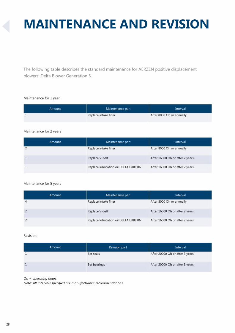
MAINTENANCE AND REVISION
The following table describes the standard maintenance for AERZEN positive displacement
blowers: Delta Blower Generation 5.
Maintenance for 1 year
Amount
1
Maintenance for 2 years
Amount
2
1
1
Maintenance for 5 years
Amount
4
2
2
Revision
Amount
1
1
Maintenance part
Replace intake filter
Maintenance part
Replace intake filter
Replace V-belt
Replace lubrication oil DELTA LUBE 06
Maintenance part
Replace intake filter
Replace V-belt
Replace lubrication oil DELTA LUBE 06
Revision part
Set seals
Set bearings
Interval
After 8000 Oh or annually
Interval
After 8000 Oh or annually
After 16000 Oh or after 2 years
After 16000 Oh or after 2 years
Interval
After 8000 Oh or annually
After 16000 Oh or after 2 years
After 16000 Oh or after 2 years
Interval
After 20000 Oh or after 3 years
After 20000 Oh or after 3 years
Oh = operating hours
Note: All intervals specified are manufacturer’s recommendations.
28

29

TECHNICAL DRAWINGS.
DELTA BLOWER GM 3 S
30
Drawing no.: 2ZG-9212
Pos.
100
610
611
613
620
1810
2110
2710
3410
3470
4420
5300
6510
6520
7110
7210
Benennung
Gebläse
Grundträger
Rohrstutzen mit integr. Rückschlagklappe
Elastischer Maschinenfuß
Motorwippe
Motor
Riementrieb
Elastische Rohrverbindung DS
Filterschalldämpfer
Ansaugfilter
Druckventil
Sonderzubehör: Anfahrentlastung
Wartungsanzeiger
Manometer
Schallhaube
Ventilator
Description
Blower
Base frame
Pipe socket with integr. check valve
Flexible machinery mounting
Hinged motor mounting plate
Motor
Belt drive
Flexible pipe connection DS
Filter silencer
Inlet filter
Pressure valve
Extras: start unloading device
Service indicator
Pressure gauge
Acoustic hood
Fan

Pos.
100
610
611
613
620
1810
2110
2410
2710
3410
3470
4420
5300
6510
6520
Benennung
Gebläse
Grundträger
Rohrstutzen mit integr. Rückschlagklappe
Elastischer Maschinenfuß
Motorwippe
Motor
Riementrieb
Riemenschutz
Elastische Rohrverbindung DS
Filterschalldämpfer
Ansaugfilter
Druckventil
Sonderzubehör: Anfahrentlastung
Wartungsanzeiger
Manometer
Description
Blower
Base frame
Pipe socket with integr. check valve
Flexible machinery mounting
Hinged motor mounting plate
Motor
Belt drive
Belt guard
Flexible pipe connection DC
Filter silencer
Inlet filter
Pressure valve
Extras: start unloading device
Service indicator
Pressure gauge
Drawing no.: 2ZG-9215
31

DELTA BLOWER GM 4 S
32
Drawing no.: ZG-00798
Pos.
100
610
611
612
613
620
1810
2110
2710
3410
3470
4420
5300
5320
6510
6520
6530
7110
7210
Benennung
Gebläse
Grundträger
Anschlussgehäuse
Rückschlagklappe
Elastischer Maschinenfuß
Motorwippe
Motor
Riementrieb
Elastische Rohrverbindung DS
Filterschalldämpfer
Ansaugfilter
Druckventil
Sonderzubehör: Anfahrentlastung
Sonderzubehör: Magnetventil
Wartungsanzeiger
Manometer
Option: Kontakt-Thermometer
Schallhaube
Ventilator
Description
Blower
Base frame
Connection housing
Check valve
Flexible machinery mounting
Hinged motor mounting plate
Motor
Belt drive
Flexible pipe connection DS
Filter silencer
Inlet filter
Pressure valve
Extras: start unloading device
Extras: solenoid valve
Service indicator
Pressure gauge
Extras: contact thermometer
Acoustic hood
Fan

Pos.
100
610
611
612
613
620
1810
2110
2410
2710
3410
3470
4420
5300
5320
Benennung
Gebläse
Grundträger
Anschlussgehäuse
Rückschlagklappe
Elastischer Maschinenfuß
Motorwippe
Motor
Riementrieb
Riemenschutz
Elastische Rohrverbindung DS
Filterschalldämpfer
Ansaugfilter
Druckventil
Sonderzubehör: Anfahrentlastung
Sonderzubehör: Magnetventil
Description
Blower
Base frame
Connection housing
Check valve
Flexible machinery mounting
Hinged motor mounting plate
Motor
Belt drive
Belt guard
Flexible pipe connection DS
Filter silencer
Inlet filter
Pressure valve
Extras: start unloading device
Extras: solenoid valve
Motoraufbau beim GM 10 S mit Motor 200 L
Motor design of GM 10 S with motor 200 L
6510
6520
7210
Wartungsanzeiger
Manometer
Ventilator
Service indicator
Pressure gauge
Fan
Drawing no.: ZG-00824
33

DELTA BLOWER GM 7 L
34
Drawing no.: ZG-00798
Pos.
100
610
611
612
613
620
1810
2110
2710
3410
3470
4420
5300
5320
6510
6520
6530
7110
7210
Benennung
Gebläse
Grundträger
Anschlussgehäuse
Rückschlagklappe
Elastischer Maschinenfuß
Motorwippe
Motor
Riementrieb
Elastische Rohrverbindung DS
Filterschalldämpfer
Ansaugfilter
Druckventil
Sonderzubehör: Anfahrentlastung
Sonderzubehör: Magnetventil
Wartungsanzeiger
Manometer
Option: Kontakt-Thermometer
Schallhaube
Ventilator
Description
Blower
Base frame
Connection housing
Check valve
Flexible machinery mounting
Hinged motor mounting plate
Motor
Belt drive
Flexible pipe connection DS
Filter silencer
Inlet filter
Pressure valve
Extras: start unloading device
Extras: solenoid valve
Service indicator
Pressure gauge
Extras: contact thermometer
Acoustic hood
Fan

Pos.
100
610
611
612
613
620
1810
2110
2410
2710
3410
3470
4420
5300
5320
Benennung
Gebläse
Grundträger
Anschlussgehäuse
Rückschlagklappe
Elastischer Maschinenfuß
Motorwippe
Motor
Riementrieb
Riemenschutz
Elastische Rohrverbindung DS
Filterschalldämpfer
Ansaugfilter
Druckventil
Sonderzubehör: Anfahrentlastung
Sonderzubehör: Magnetventil
Description
Blower
Base frame
Connection housing
Check valve
Flexible machinery mounting
Hinged motor mounting plate
Motor
Belt drive
Belt guard
Flexible pipe connection DS
Filter silencer
Inlet filter
Pressure valve
Extras: start unloading device
Extras: solenoid valve
Motoraufbau beim GM 10 S mit Motor 200 L
Motor design of GM 10 S with motor 200 L
6510
6520
7210
Wartungsanzeiger
Manometer
Ventilator
Service indicator
Pressure gauge
Fan
Drawing no.: ZG-00824
35

1 2
30±
5
294±
5
300
240
1 8
0
20
1 5
00
1 0
39
1 0
5
DELTA BLOWER GM 10 S
1350
3450 3410,3470
II
Zuluft
4420
7210
320±5
612
100
Kabelzuführung 2xØ54 /1xØ32,5
cable lead 2xØ54 /1xØ32,5
611
2710
Abluft
F
610
40 60
880
Erdungsanschluss M8
earthing connection
375±5
exhaust-air 33
495±5
580
1394±5
(319 )
7110
4
x
Ø
1
5
1163
90
2110
Ölstand
oil level
Drehrichtung
sense of rotation
1810
5310
Kabelzuführung
cable lead
620
613
214 624
610 ()110
1250 Pos.
100
610
611
612
613
620
1810
2110
2710
3410
3470
3450
4420
5310
6510
6520
6530
7110
7210
Benennung
Gebläse
Grundträger
Anschlussgehäuse
Rückschlagklappe
Elastischer Maschinenfuß
Motorwippe
Motor
Riementrieb
Elastische Rohrverbindung DS
Filterschalldämpfer
Ansaugfilter
Option: Elastische Rohrverbindung SS
Druckventil
Option: Anfahrentlastung
Wartungsanzeiger
Manometer
Option: Kontakt-Thermometer
Schallhaube
Ventilator
Description
Blower
Base frame
Connection housing
Check valve
Flexible machinery mounting
Hinged motor mounting plate
Motor
Belt drive
Flexible pipe connection DS
Filter silencer
Inlet filter
Optional: flexible pipe connection SS
Pressure valve
Optional: start unloading device
Service indicator
Pressure gauge
Extras: contact thermometer
Acoustic hood
Fan
Drawing no.: 4000146592
36

fürfür Stirnseitig min. for for work at front side side of
3450
II
100
4420
611,612
I
F
320±5
3410,3470
6510
6520
610
2710
Erdungsanschluss Ø9
earthing connection Ø9
495±5
580
613
160±5 135
1264±5 1172
2410
Kabelzuführung
cable lead
2110
Drehrichtung sense of rotation
1810
5310
610
()110
620
Freiraum Wartungsarbeiten Stirnseitig800min. 800mm
Free space maintenance work at front packagedunit 800mm min.
1007
Pos.
100
610
611
612
613
620
1810
2110
2410
2710
3410
3470
3450
4420
5310
6510
6520
7210
Benennung
Gebläse
Grundträger
Anschlussgehäuse
Rückschlagklappe
Elastischer Maschinenfuß
Motorwippe
Motor
Riementrieb
Riemenschutz
Elastische Rohrverbindung DS
Saugschalldämpfer
Ansaugfilter
Option: Elastische Rohrverbindung SS
Druckventil
Option: Anfahrentlastung
Wartungsanzeiger
Manometer
Ventilator
Description
Blower
Base frame
Connection housing
Check valve
Flexible machinery mounting
Hinged motor mounting plate
Motor
Belt drive
Belt guard
Flexible pipe connection DS
Suction silencer
Inlet filter
Optional: flexible pipe connection SS
Pressure valve
Optional: start unloading device
Service indicator
Pressure gauge
Fan
Drawing no.: 4000150127
37

DELTA BLOWER GM 10 S
Erdungsanschluß ø9
earthing connection ø9
Erdungsanschluß M8
earthing connection M8 Pos.
100
610
611
612
613
620
1810
2110
2710
3410
3470
4420
5300
5320
6510
6520
6530
7110
7210
Benennung
Gebläse
Grundträger
Anschlussgehäuse
Rückschlagklappe
Elastischer Maschinenfuß
Motorwippe
Motor
Riementrieb
Elastische Rohrverbindung DS
Filterschalldämpfer
Ansaugfilter
Druckventil
Sonderzubehör: Anfahrentlastung
Sonderzubehör: Magnetventil
Wartungsanzeiger
Manometer
Option: Kontakt-Thermometer
Schallhaube
Ventilator
Description
Blower
Base frame
Connection housing
Check valve
Flexible machinery mounting
Hinged motor mounting plate
Motor
Belt drive
Flexible pipe connection DS
Filter silencer
Inlet filter
Pressure valve
Extras: start unloading device
Extras: solenoid valve
Service indicator
Pressure gauge
Extras: contact thermometer
Acoustic hood
Fan
Drawing no.: ZG-00798
38

Erdungsanschluß ø9
earthing connection ø9
Pos.
100
610
611
612
613
620
1810
2110
2410
2710
3410
3470
4420
5300
5320
Benennung
Gebläse
Grundträger
Anschlussgehäuse
Rückschlagklappe
Elastischer Maschinenfuß
Motorwippe
Motor
Riementrieb
Riemenschutz
Elastische Rohrverbindung DS
Filterschalldämpfer
Ansaugfilter
Druckventil
Sonderzubehör: Anfahrentlastung
Sonderzubehör: Magnetventil
Description
Blower
Base frame
Connection housing
Check valve
Flexible machinery mounting
Hinged motor mounting plate
Motor
Belt drive
Belt guard
Flexible pipe connection DS
Filter silencer
Inlet filter
Pressure valve
Extras: start unloading device
Extras: solenoid valve
Motoraufbau beim GM 10 S mit Motor 200 L
Motor design of GM 10 S with motor 200 L
6510
6520
7210
Wartungsanzeiger
Manometer
Ventilator
Service indicator
Pressure gauge
Fan
Drawing no.: ZG-00824
39
1 2
30±
5
294±
5
300
240
1 8
0
20
1 5
00
1 0
39
1 0
5
Zuluft
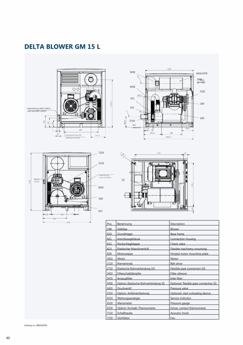
DELTA BLOWER GM 15 L
1350
3450 3410,3470
II
Zuluft
air inlet
4420
7210
320±5
612
100
Kabelzuführung 2xØ54 /1xØ32,5
cable lead 2xØ54 /1xØ32,5
611
2710
Abluft
F
610
40 60
880
Erdungsanschluss M8
earthing connection
375±5
exhaust-air 33
495±5
580
1394±5
(319 )
7110
4
x
Ø
1
5
1163
90
2110
Ölstand
oil level
Drehrichtung
sense of rotation
1810
5310
Kabelzuführung
cable lead
620
613
214 624
610 ()110
1250 Pos.
100
610
611
612
613
620
1810
2110
2710
3410
3470
3450
4420
5310
6510
6520
6530
7110
7210
Benennung
Gebläse
Grundträger
Anschlussgehäuse
Rückschlagklappe
Elastischer Maschinenfuß
Motorwippe
Motor
Riementrieb
Elastische Rohrverbindung DS
Filterschalldämpfer
Ansaugfilter
Option: Elastische Rohrverbindung SS
Druckventil
Option: Anfahrentlastung
Wartungsanzeiger
Manometer
Option: Kontakt-Thermometer
Schallhaube
Ventilator
Description
Blower
Base frame
Connection housing
Check valve
Flexible machinery mounting
Hinged motor mounting plate
Motor
Belt drive
Flexible pipe connection DS
Filter silencer
Inlet filter
Optional: flexible pipe connection SS
Pressure valve
Optional: start unloading device
Service indicator
Pressure gauge
Extras: contact thermometer
Acoustic hood
Fan
Drawing no.: 4000146592
40

3450
II
100
4420
611,612
I
F
320±5
3410,3470
6510
6520
610
2710
Erdungsanschluss Ø9
earthing connection Ø9
495±5
580
613
160±5 135
1264±5 1172
2410
Kabelzuführung
cable lead
2110
Drehrichtung sense of rotation
1810
5310
610
()110
620
Freiraum für Wartungsarbeiten Stirnseitig min. 800mm
Free space for maintenance work at front side of unit 800mm min.
1007
Pos.
100
610
611
612
613
620
1810
2110
2410
2710
3410
3470
3450
4420
5310
6510
6520
7210
Benennung
Gebläse
Grundträger
Anschlussgehäuse
Rückschlagklappe
Elastischer Maschinenfuß
Motorwippe
Motor
Riementrieb
Riemenschutz
Elastische Rohrverbindung DS
Saugschalldämpfer
Ansaugfilter
Option: Elastische Rohrverbindung SS
Druckventil
Option: Anfahrentlastung
Wartungsanzeiger
Manometer
Ventilator
Description
Blower
Base frame
Connection housing
Check valve
Flexible machinery mounting
Hinged motor mounting plate
Motor
Belt drive
Belt guard
Flexible pipe connection DS
Suction silencer
Inlet filter
Optional: flexible pipe connection SS
Pressure valve
Optional: start unloading device
Service indicator
Pressure gauge
Fan
Drawing no.: 4000150127
41
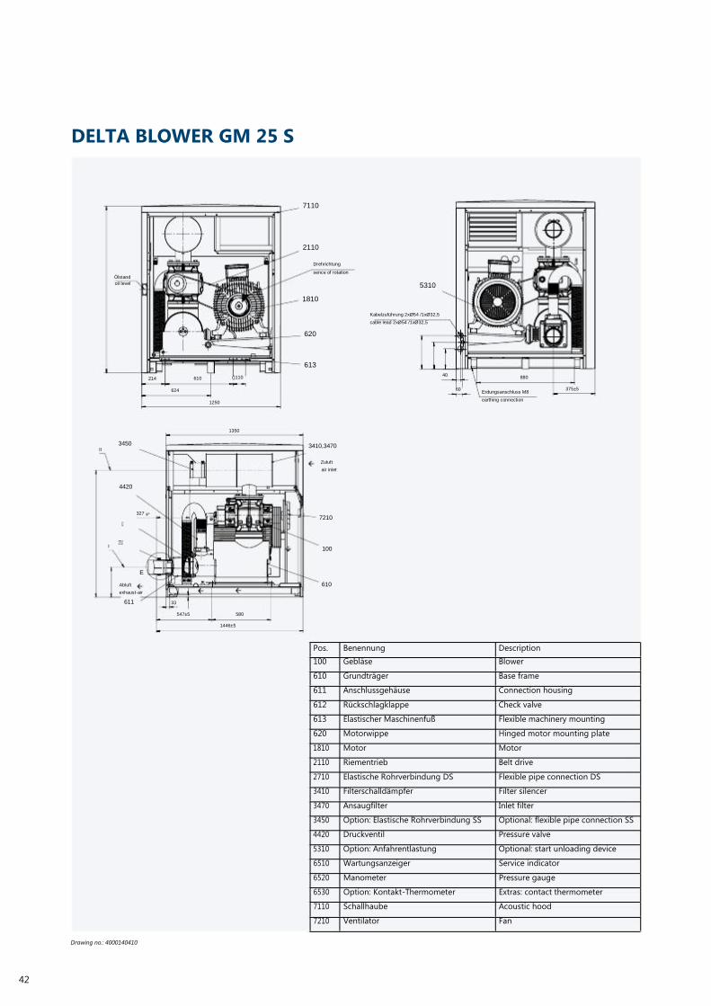
DELTA BLOWER GM 25 S
7110
2110
Ölstand
oil level
Drehrichtung
sence of rotation
5310
1810
Kabelzuführung 2xØ54 /1xØ32,5
cable lead 2xØ54 /1xØ32,5
620
613
214 610 ()110 40
880
624 1250
60 Erdungsanschluss M8
earthing connection
375±5
1350
II
3450 3410,3470
Zuluft
air inlet
4420
I
612
2710
327
5
7210
100
E
Abluft
exhaust-air
611
33
610
547±5 580
1446±5
42
Drawing no.: 4000140410
Pos.
100
610
611
612
613
620
1810
2110
2710
3410
3470
3450
4420
5310
6510
6520
6530
7110
7210
Benennung
Gebläse
Grundträger
Anschlussgehäuse
Rückschlagklappe
Elastischer Maschinenfuß
Motorwippe
Motor
Riementrieb
Elastische Rohrverbindung DS
Filterschalldämpfer
Ansaugfilter
Option: Elastische Rohrverbindung SS
Druckventil
Option: Anfahrentlastung
Wartungsanzeiger
Manometer
Option: Kontakt-Thermometer
Schallhaube
Ventilator
Description
Blower
Base frame
Connection housing
Check valve
Flexible machinery mounting
Hinged motor mounting plate
Motor
Belt drive
Flexible pipe connection DS
Filter silencer
Inlet filter
Optional: flexible pipe connection SS
Pressure valve
Optional: start unloading device
Service indicator
Pressure gauge
Extras: contact thermometer
Acoustic hood
Fan

3410,3470
2110
1810
3410,3470
2110
1810
Drehrichtung
sence of rotation
620
613
Drehrichtung
sence of rotation
620
613
610 1007
()110 610
1007
()110
Kabelzuführung
cable lead
5310
160±5 134
1171±5
Pos.
100
610
611
612
613
620
1810
2110
2410
2710
3410
3450
3470
4420
5310
6510
6520
7210
Benennung
Gebläse
Grundträger
Anschlussgehäuse
Rückschlagklappe
Elastischer Maschinenfuß
Motorwippe
Motor
Riementrieb
Riemenschutz
Elastische Rohrverbindung DS
Filterschalldämpfer
Option: Elastische Rohrverbindung SS
Ansaugfilter
Druckventil
Option: Anfahrentlastung
Wartungsanzeiger
Manometer
Ventilator
Description
Blower
Base frame
Connection housing
Check valve
Flexible machinery mounting
Hinged motor mounting plate
Motor
Belt drive
Belt guard
Flexible pipe connection DS
Filter silencer
Optional: flexible pipe connection SS
Inlet filter
Pressure valve
Optional: start unloading device
Service indicator
Pressure gauge
Fan
Drawing no.: 4000157416
43

DELTA BLOWER GM 30 L
Erdungsanschluß 11
earthing connection ø11
44
Drawing no.: 4000148572
Pos.
100
610
611
612
613
620
1810
2110
2410
2710
3410
3470
3450
4420
5310
5320
6510
6511
6520
6530
6521
7110
7210
Benennung
Gebläse
Grundträger
Anschlussgehäuse
Rückschlagklappe
Elastischer Maschinenfuß
Motorwippe
Motor
Riementrieb
Sonderzubehör: Riemenschutz
Elastische Rohrverbindung DS
Filterschalldämpfer
Ansaugfilter
Option: Elastische Rohrverbindung SS
Druckventil
Sonderzubehör: Anfahrentlastung
Sonderzubehör: Magnetventil
Wartungsanzeiger
Sonderzubehör: Druckwächter SS
Manometer
Sonderzubehör: Druckschalter DS
Sonderzubehör: Kontakt-Thermometer
Schallhaube
Ventilator
Description
Blower
Base frame
Connection housing
Check valve
Flexible machinery mounting
Hinged motor mounting plate
Motor
Belt drive
Extras: belt guard
Flexible pipe connection DS
Filter silencer
Inlet filter
Optional: flexible pipe connection SS
Pressure valve
Extras: start unloading device
Extras: solenoid valve
Service indicator
Extras: pressure switch SS
Pressure gauge
Extras: pressure switch DS
Extras: contact thermometer
Acoustic hood
Fan

Pos.
100
610
611
612
613
620
1810
2110
2410
2710
3410
3470
4420
5310
5320
6510
6520
Benennung
Gebläse
Grundträger
Anschlussgehäuse
Rückschlagklappe
Elastischer Maschinenfuß
Motorwippe
Motor
Riementrieb
Riemenschutz
Elastische Rohrverbindung DS
Filterschalldämpfer
Ansaugfilter
Druckventil
Sonderzubehör: Anfahrentlastung
Sonderzubehör: Magnetventil
Wartungsanzeiger
Manometer
Description
Blower
Base frame
Connection housing
Check valve
Flexible machinery mounting
Hinged motor mounting plate
Motor
Belt drive
Belt guard
Flexible pipe connection DS
Filter silencer
Inlet filter
Pressure valve
Extras: start unloading device
Extras: solenoid valve
Service indicator
Pressure gauge
Drawing no.: 4000148480
45

DELTA BLOWER GM 35 S
Erdungsanschluß ø11
earthing connection ø11
46
Drawing no.: 4000148572
Pos.
100
610
611
612
613
620
1810
2110
2410
2710
3410
3470
3450
4420
5310
5320
6510
6511
6520
6530
6521
7110
7210
Benennung
Gebläse
Grundträger
Anschlussgehäuse
Rückschlagklappe
Elastischer Maschinenfuß
Motorwippe
Motor
Riementrieb
Sonderzubehör: Riemenschutz
Elastische Rohrverbindung DS
Filterschalldämpfer
Ansaugfilter
Option: Elastische Rohrverbindung SS
Druckventil
Sonderzubehör: Anfahrentlastung
Sonderzubehör: Magnetventil
Wartungsanzeiger
Sonderzubehör: Druckwächter SS
Manometer
Sonderzubehör: Druckschalter DS
Sonderzubehör: Kontakt-Thermometer
Schallhaube
Ventilator
Description
Blower
Base frame
Connection housing
Check valve
Flexible machinery mounting
Hinged motor mounting plate
Motor
Belt drive
Extras: belt guard
Flexible pipe connection DS
Filter silencer
Inlet filter
Optional: flexible pipe connection SS
Pressure valve
Extras: start unloading device
Extras: solenoid valve
Service indicator
Extras: pressure switch SS
Pressure gauge
Extras: pressure switch DS
Extras: contact thermometer
Acoustic hood
Fan

Pos.
100
610
611
612
613
620
1810
2110
2410
2710
3410
3470
4420
5310
5320
6510
6520
Benennung
Gebläse
Grundträger
Anschlussgehäuse
Rückschlagklappe
Elastischer Maschinenfuß
Motorwippe
Motor
Riementrieb
Riemenschutz
Elastische Rohrverbindung DS
Filterschalldämpfer
Ansaugfilter
Druckventil
Sonderzubehör: Anfahrentlastung
Sonderzubehör: Magnetventil
Wartungsanzeiger
Manometer
Description
Blower
Base frame
Connection housing
Check valve
Flexible machinery mounting
Hinged motor mounting plate
Motor
Belt drive
Belt guard
Flexible pipe connection DS
Filter silencer
Inlet filter
Pressure valve
Extras: start unloading device
Extras: solenoid valve
Service indicator
Pressure gauge
Drawing no.: 4000148480
47

357
±5
55 34
44
282
1268
Ölstand
x ø14 für
DELTA BLOWER GM 50 L
6510
6520
6530
Ölstand
oil level 6511
2410
Kabelzuführung
cable lead
1xØ64/ 2xØ32,5
207 272
525 ±5
618
1088
349
4xØ14 für
4BefestigungBefestigung
4 x ø14 for fastening
Kabelzuführung
5300
5320
Abluft
exhaust air
Erdungsanschluß ø11
earthing connection ø11 Pos.
100
610
611
612
613
620
1810
2110
276
Benennung
Gebläse
Grundträger
Anschlussgehäuse
Rückschlagklappe
Elastischer Maschinenfuß
Motorwippe
Motor
Riementrieb
1538 Description
Blower
Base frame
Connection housing
Check valve
Flexible machinery mounting
Hinged motor mounting plate
Motor
Belt drive
48
Drawing no.: 4000146628
2410
2710
3410
3470
4420
5310
5320
6510
6511
6520
6530
6521
7110
7210
Sonderzubehör: Riemenschutz
Elastische Rohrverbindung DS
Filterschalldämpfer
Ansaugfilter
Druckventil
Sonderzubehör: Anfahrentlastung
Sonderzubehör: Magnetventil
Wartungsanzeiger
Sonderzubehör: Druckwächter SS
Manometer
Sonderzubehör: Druckschalter DS
Sonderzubehör: Kontakt-Thermometer
Schallhaube
Ventilator
Extras: belt guard
Flexible pipe connection DS
Filter silencer
Inlet filter
Pressure valve
Extras: start unloading device
Extras: solenoid valve
Service indicator
Extras: pressure switch SS
Pressure gauge
Extras: pressure switch DS
Extras: contact thermometer
Acoustic hood
Fan

Erdungsanschluß ø11
earthing connection ø11
Pos.
100
610
611
612
613
620
1810
2110
2710
3410
3470
4420
5310
5320
6520
6510
Benennung
Gebläse
Grundträger
Anschlussgehäuse
Rückschlagklappe
Elastischer Maschinenfuß
Motorwippe
Motor
Riementrieb
Elastische Rohrverbindung DS
Filterschalldämpfer
Ansaugfilter
Druckventil
Sonderzubehör: Anfahrentlastung
Sonderzubehör: Magnetventil
Manometer
Wartungsanzeiger
Description
Blower
Base frame
Connection housing
Check valve
Flexible machinery mounting
Hinged motor mounting plate
Motor
Belt drive
Flexible pipe connection DS
Filter silencer
Inlet filter
Pressure valve
Extras: start unloading device
Extras: solenoid valve
Pressure gauge
Service indicator
Drawing no.: 4000144598
49
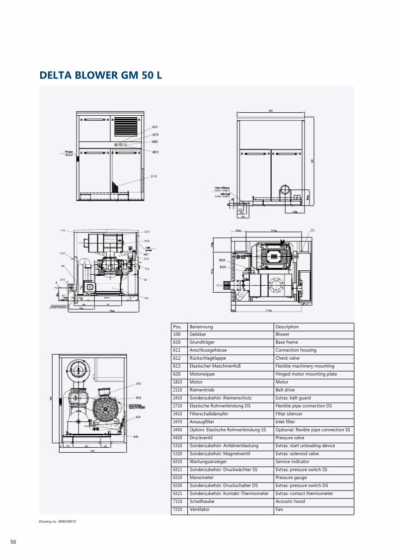
DELTA BLOWER GM 50 L
Erdungsanschluß ø11
earthing connection ø11
50
Drawing no.: 4000148572
Pos.
100
610
611
612
613
620
1810
2110
2410
2710
3410
3470
3450
4420
5310
5320
6510
6511
6520
6530
6521
7110
7210
Benennung
Gebläse
Grundträger
Anschlussgehäuse
Rückschlagklappe
Elastischer Maschinenfuß
Motorwippe
Motor
Riementrieb
Sonderzubehör: Riemenschutz
Elastische Rohrverbindung DS
Filterschalldämpfer
Ansaugfilter
Option: Elastische Rohrverbindung SS
Druckventil
Sonderzubehör: Anfahrentlastung
Sonderzubehör: Magnetventil
Wartungsanzeiger
Sonderzubehör: Druckwächter SS
Manometer
Sonderzubehör: Druckschalter DS
Sonderzubehör: Kontakt-Thermometer
Schallhaube
Ventilator
Description
Blower
Base frame
Connection housing
Check valve
Flexible machinery mounting
Hinged motor mounting plate
Motor
Belt drive
Extras: belt guard
Flexible pipe connection DS
Filter silencer
Inlet filter
Optional: flexible pipe connection SS
Pressure valve
Extras: start unloading device
Extras: solenoid valve
Service indicator
Extras: pressure switch SS
Pressure gauge
Extras: pressure switch DS
Extras: contact thermometer
Acoustic hood
Fan

Pos.
100
610
611
612
613
620
1810
2110
2410
2710
3410
3470
4420
5310
5320
6510
6520
Benennung
Gebläse
Grundträger
Anschlussgehäuse
Rückschlagklappe
Elastischer Maschinenfuß
Motorwippe
Motor
Riementrieb
Riemenschutz
Elastische Rohrverbindung DS
Filterschalldämpfer
Ansaugfilter
Druckventil
Sonderzubehör: Anfahrentlastung
Sonderzubehör: Magnetventil
Wartungsanzeiger
Manometer
Description
Blower
Base frame
Connection housing
Check valve
Flexible machinery mounting
Hinged motor mounting plate
Motor
Belt drive
Belt guard
Flexible pipe connection DS
Filter silencer
Inlet filter
Pressure valve
Extras: start unloading device
Extras: solenoid valve
Service indicator
Pressure gauge
Drawing no.: 4000148480
51

34
55
1268
282
357
±5
44
Ölstand
x ø14 für
DELTA BLOWER GM 60 S
6510
6520
6530
Ölstand
oil level 6511
2410
Kabelzuführung
cable lead
1xØ64/ 2xØ32,5
207 272
525 ±5
618
1088
349
4xØ14 für
4BefestigungBefestigung
4 x ø14 for fastening
Kabelzuführung
cable lead
5300
5320
Abluft
exhaust-air
Erdungsanschluß ø11
earthing connection ø11 Pos.
100
610
611
612
613
620
1810
2110
276
Benennung
Gebläse
Grundträger
Anschlussgehäuse
Rückschlagklappe
Elastischer Maschinenfuß
Motorwippe
Motor
Riementrieb
1538 Description
Blower
Base frame
Connection housing
Check valve
Flexible machinery mounting
Hinged motor mounting plate
Motor
Belt drive
52
Drawing no.: 4000146628
2410
2710
3410
3470
4420
5310
5320
6510
6511
6520
6530
6521
7110
7210
Sonderzubehör: Riemenschutz
Elastische Rohrverbindung DS
Filterschalldämpfer
Ansaugfilter
Druckventil
Sonderzubehör: Anfahrentlastung
Sonderzubehör: Magnetventil
Wartungsanzeiger
Sonderzubehör: Druckwächter SS
Manometer
Sonderzubehör: Druckschalter DS
Sonderzubehör: Kontakt-Thermometer
Schallhaube
Ventilator
Extras: belt guard
Flexible pipe connection DS
Filter silencer
Inlet filter
Pressure valve
Extras: start unloading device
Extras: solenoid valve
Service indicator
Extras: pressure monitor SS
Pressure gauge
Extras: pressure switch DS
Extras: contact thermometer
Acoustic hood
Fan

Erdungsanschluß ø11
earthing connection ø11
Pos.
100
610
611
612
613
620
1810
2110
2710
3410
3470
4420
5310
5320
6520
6510
Benennung
Gebläse
Grundträger
Anschlussgehäuse
Rückschlagklappe
Elastischer Maschinenfuß
Motorwippe
Motor
Riementrieb
Elastische Rohrverbindung DS
Filterschalldämpfer
Ansaugfilter
Druckventil
Sonderzubehör: Anfahrentlastung
Sonderzubehör: Magnetventil
Manometer
Wartungsanzeiger
Description
Blower
Base frame
Connection housing
Check valve
Flexible machinery mounting
Hinged motor mounting plate
Motor
Belt drive
Flexible pipe connection DS
Filter silencer
Inlet filter
Pressure valve
Extras: start unloading device
Extras: solenoid valve
Pressure gauge
Service indicator
Drawing no.: 4000144598
53

27 3
(D
N250)Ø
55
320
2345
1 4
58
10
(1 2
2)
52
32
456
DELTA BLOWER GM 80 L
3410
6510
6520
7110
3410
100
2410
optional
4420
1810
4450
7220
Ölstand
oil level
2110
Drehrichtung
sense of rotation
2150
611
2710
Rückschlagklappe
200
10
7276
2110
284
950
1900
(666)
Erdungsanschluß
earth connection
26 Ø
11 769
950
(481)
90 10 2200
610 613 620
331
610
6 20
1820
1538
1810
2150
(331)
4420
5310
(4x) 14
optional
6520
1810
5310
optional
611 6510
2110
1820
X
3410
620 2710
2410
2150 64
64
4450 331
1653
(216)
optional
32,3
60
213
120
5
Kabelzuführung
cable entry
Erdungsanschluß
earthingconnection
X 594
10
Pos.
Benennung
Description
773 100
610
611
611
613
620
1810
1820
2110
2150
2410
2710
2710
3410
4420
5310
6510
6520
7110
7210
7276
Gebläse
Grundträger
Anschlussgehäuse mit Flansch
Anschlussgehäuse
Elastischer Maschinenfuß
Motorwippe
Motor
Motorbefestigung
Riementrieb
Hebevorrichtung
Optional: Riemenschutz
Elastische Rohrverbindung DS + Muffe
Elastische Rohrverbindung DS + Kom-
pensator
Filterschalldämpfer
Druckventil
Anfahrentlastung
Wartungsanzeiger
Manometer
Schallhaube
Ventilator
Ölstandanzeiger
Blower
Base frame
Connection housing with flange
Connection housing
Flexible machinery mounting
Hinged motor mounting plate
Motor
Motor fastening
Belt drive
Lifting device
Extras: belt guard
Flexible pipe connection DS + sleeve
Flexible pipe connection DS + com-
pensator
Filter silencer
Pressure valve
Start unloading device
Service indicator
Pressure gauge
Acoustic hood
Fan
Oil level indicator
Drawing no.: 4000165787
54

(1648)
34
5
125
2062
3410
6510
2410
6520
68
2110
1810
Drehrichtung
sense of rotation
2150
620
4420
611
2710
200
20
6510
100
2410
6520
610
(492) 367 10 950 (253)
859 10
85
34
5
950
125
2062
613 610
3410
13
13 ÿ
ÿ
4420
611
2710
200
6510
100
2410
20
6520
610
(492) 367 10 950 (253)
85
9
13
13 ÿ
ÿ
10
Pos.
100
Benennung
Gebläse
Description
Blower
610 Grundträger Base frame
2710
5310
optional
1810 611
611
613
620
1810
1820
2110
2150
2410
2710
2710
Anschlussgehäuse mit Muffe
Anschlussgehäuse mit Flansch
Elastischer Maschinenfuß
Motorwippe
Motor
Motorbefestigung
Riementrieb
Hebevorrichtung
Riemenschutz
Elastische Rohrverbindung DS + Muffe
Elastische Rohrverbindung DS + Kom-
pensator
Connection housing for sleeve
Connection housing with flange
Flexible machinery mounting
Hinged motor mounting plate
Motor
Motor fastening
Belt drive
Lifting device
belt guard
Flexible pipe connection DS + sleeve
Flexible pipe connection DS + com-
pensator
611 3410 610 2410 3410 Filterschalldämpfer Filter silencer
3450
4420
5310
6510
6520
Elastischer Rohranschluss SS
Ventil
Anfahrentlastung
Wartungsanzeiger
Manometer
Flexible pipe connection SS
Valve
Start unloading device
Service indicator
Pressure gauge
Drawing no.: 4000096477
55

27 3
(D
N250)Ø
55
320
2345
1 4
58
10
(1 2
2)
52
32
456
Erdungsanschluß
DELTA BLOWER GM 90 S
3410
6510
6520
7110
3410
100
2410
optional
4420
1810
4450
7220
Ölstand
oil level
2110
Drehrichtung
sense of rotation
2150
611
2710
Rückschlagklappe
200
10
7276
2110
284
950
1900
(666)
Erdungsanschluß
earth connection
26 Ø
11 769
950
(481)
90 10 2200
610 613 620
331
610
6 20
1820
1538
1810
2150
(331)
4420
5310
(4x) 14
optional
6520
1810
5310
optional
611 6510
2110
1820
X
3410
620 2710
2410
2150 64
64
4450 331
1653
(216)
optional
32,3
60
213
120
5
Kabelzuführung
cable entry
Erdungsanschluß
earthingconnection
X 594
10
Pos.
Benennung
Description
773 100
610
611
611
613
620
1810
1820
2110
2150
2410
2710
2710
3410
4420
5310
6510
6520
7110
7210
7276
Gebläse
Grundträger
Anschlussgehäuse mit Flansch
Anschlussgehäuse
Elastischer Maschinenfuß
Motorwippe
Motor
Motorbefestigung
Riementrieb
Hebevorrichtung
Optional: Riemenschutz
Elastische Rohrverbindung DS + Muffe
Elastische Rohrverbindung DS + Kom-
pensator
Filterschalldämpfer
Druckventil
Anfahrentlastung
Wartungsanzeiger
Manometer
Schallhaube
Ventilator
Ölstandanzeiger
Blower
Base frame
Connection housing with flange
Connection housing
Flexible machinery mounting
Hinged motor mounting plate
Motor
Motor fastening
Belt drive
Lifting device
Extras: belt guard
Flexible pipe connection DS + sleeve
Flexible pipe connection DS + com-
pensator
Filter silencer
Pressure valve
Start unloading device
Service indicator
Pressure gauge
Acoustic hood
Fan
Oil level indicator
Drawing no.: 4000165787
56

(1648)
34
5
125
2062
3410
6510
2410
6520
68
2110
1810
Drehrichtung
sense of rotation
2150
620
4420
611
2710
200
20
6510
100
2410
6520
610
(492) 367 10 950 (253)
859 10
85
34
5
950
125
2062
613 610
3410
13
13 ÿ
ÿ
4420
611
2710
200
6510
100
2410
20
6520
610
(492) 367 10 950 (253)
85
9
13
13 ÿ
ÿ
10
Pos.
100
Benennung
Gebläse
Description
Blower
610 Grundträger Base frame
2710
5310
optional
1810 611
611
613
620
1810
1820
2110
2150
2410
2710
2710
Anschlussgehäuse mit Muffe
Anschlussgehäuse mit Flansch
Elastischer Maschinenfuß
Motorwippe
Motor
Motorbefestigung
Riementrieb
Hebevorrichtung
Riemenschutz
Elastische Rohrverbindung DS + Muffe
Elastische Rohrverbindung DS + Kom-
pensator
Connection housing with sleeve
Connection housing with flange
Flexible machinery mounting
Hinged motor mounting plate
Motor
Motor fastening
Belt drive
Lifting device
belt guard
Flexible pipe connection DS + sleeve
Flexible pipe connection DS + com-
pensator
611 3410 610 2410 3410 Filterschalldämpfer Filter silencer
3450
4420
5310
6510
6520
Elastischer Rohranschluss SS
Ventil
Anfahrentlastung
Wartungsanzeiger
Manometer
Flexible pipe connection SS
Valve
Start unloading device
Service indicator
Pressure gauge
Drawing no.: 4000096477
57

DELTA BLOWER GM 130 L
58
Drawing no.: 4900105335
Pos.
100
610
611
612
613
620
1810
2110
2710
3410
3470
4420
5310
6510
6520
7110
7210
Benennung
Gebläse
Grundträger
Anschlussgehäuse
Rückschlagklappe
Elastischer Maschinenfuß
Motorwippe
Motor
Riementrieb
Elastische Rohrverbindung DS
Filterschalldämpfer
Ansaugfilter
Druckventil
Sonderzubehör: Anfahrentlastung
Wartungsanzeiger
Manometer
Schallhaube
Ventilator
Description
Blower
Base frame
Connection housing
Check valve
Flexible machinery mounting
Hinged motor mounting plate
Motor
Belt drive
Flexible pipe connection DS
Filter silencer
Inlet filter
Pressure valve
Extras: start unloading device
Service indicator
Pressure gauge
Acoustic hood
Fan

Pos.
100
610
611
612
613
1810
2110
2410
2710
3410
3470
4420
5310
6510
6520
Benennung
Gebläse
Grundträger
Anschlussgehäuse
Rückschlagklappe
Elastischer Maschinenfuß
Motor
Riementrieb
Riemenschutz
Elastische Rohrverbindung DS
Filterschalldämpfer
Ansaugfilter
Druckventil
Sonderzubehör: Anfahrentlastung
Wartungsanzeiger
Manometer
Description
Blower
Base frame
Connection housing
Check valve
Flexible machinery mounting
Motor
Belt drive
Belt guard
Flexible pipe connection DS
Filter silencer
Inlet filter
Pressure valve
Extras: start unloading device
Service indicator
Pressure gauge
Drawing no.: ZG-02414
59

DELTA BLOWER GM 150 S
60
Drawing no.: 4900105335
Pos.
100
610
611
612
613
620
1810
2110
2710
3410
3470
4420
5310
6510
6520
7110
7210
Benennung
Gebläse
Grundträger
Anschlussgehäuse
Rückschlagklappe
Elastischer Maschinenfuß
Motorwippe
Motor
Riementrieb
Elastische Rohrverbindung DS
Filterschalldämpfer
Ansaugfilter
Druckventil
Sonderzubehör: Anfahrentlastung
Wartungsanzeiger
Manometer
Schallhaube
Ventilator
Description
Blower
Base frame
Connection housing
Check valve
Flexible machinery mounting
Hinged motor mounting plate
Motor
Belt drive
Flexible pipe connection DS
Filter silencer
Inlet filter
Pressure valve
Extras: start unloading device
Service indicator
Pressure gauge
Acoustic hood
Fan

Pos.
100
610
611
612
613
1810
2110
2410
2710
3410
3470
4420
5310
6510
6520
Benennung
Gebläse
Grundträger
Anschlussgehäuse
Rückschlagklappe
Elastischer Maschinenfuß
Motor
Riementrieb
Riemenschutz
Elastische Rohrverbindung DS
Filterschalldämpfer
Ansaugfilter
Druckventil
Sonderzubehör: Anfahrentlastung
Wartungsanzeiger
Manometer
Description
Blower
Base frame
Connection housing
Check valve
Flexible machinery mounting
Motor
Belt drive
Belt guard
Flexible pipe connection DS
Filter silencer
Inlet filter
Pressure valve
Extras: start unloading device
Service indicator
Pressure gauge
Drawing no.: ZG-02414
61

DELTA BLOWER GM 220 L
Kabelzuführung
cable lead
Drehrichtung
sens of rotation
Erdungsanschluß M10
earthing connection M10
Zuluft
Axialventilator
axial fan
Abluft
exhaust air
air inlet
Instrumententableau
Instrumentation
Liefergrenze
supply limit
62
Drawing no.: 0ZG-852
Pos.
1
2
4
7
8
16
18
28
30
31
33
50
51
21
56
71
75
Benennung
Gebläse
Motor
Elastischer Maschinenfuß
Riementrieb
Riemenschutz
Elastische Rohrverbindung DS
Druckventil
Motorwippe
Grundträger
Saugschalldämpfer
Anschlussgehäuse
Schallhaube
Ventilator
Sonderzubehör: Anfahrentlastung
Sonderzubehör: Regendach
Sonderzubehör: Manometer
Sonderzubehör: Wartungsanzeiger
Description
Blower
Motor
Flexible machinery mounting
Belt drive
Belt guard
Flexible pipe connection DS
Pressure valve
Hinged motor mounting plate
Base frame
Suction silencer
Connection housing
Acoustic hood
Fan
Extras: start unloading device
Extras: shelter
Extras: pressure gauge
Extras: service indicator

2
Drehrichtung
sens of rotation
Erdungsanschluß M10
earthing connection M10
Zuluft
air inlet
Liefergrenze
supply limit
Pos.
1
2
4
7
8
11
16
18
28
30
31
33
21
71
75
Benennung
Gebläse
Motor
Elastischer Maschinenfuß
Riementrieb
Riemenschutz
Ansaugfilter
Elastische Rohrverbindung DS
Druckventil
Motorwippe
Grundträger
Saugschalldämpfer
Anschlussgehäuse mit integr. Rückschlag-
klappe
Sonderzubehör: Anfahrentlastung
Sonderzubehör: Manometer
Sonderzubehör: Wartungsanzeiger
Description
Blower
Motor
Flexible machinery mounting
Belt drive
Belt guard
Inlet filter
Flexible pipe connection DS
Pressure valve
Hinged motor mounting plate
Base frame
Suction silencer
Connection housing with integr. check
valve
Extras: start unloading device
Extras: pressure gauge
Extras: service indicator
Drawing no.: 0ZG-851
63

DELTA BLOWER GM 240 S
Kabelzuführung
cable lead
Drehrichtung
sens of rotation
Erdungsanschluß M10
earthing connection M10
Axialventilator
axial fan
Abluft
Zuluft exhaust air
air inlet
Instrumententableau
Instrumentation
Liefergrenze
supply limit
64
Drawing no.: 0ZG-852
Pos.
1
2
4
7
8
16
18
28
30
31
33
50
51
21
56
71
75
Benennung
Gebläse
Motor
Elastischer Maschinenfuß
Riementrieb
Riemenschutz
Elastische Rohrverbindung DS
Druckventil
Motorwippe
Grundträger
Saugschalldämpfer
Anschlussgehäuse
Schallhaube
Ventilator
Sonderzubehör: Anfahrentlastung
Sonderzubehör: Regendach
Sonderzubehör: Manometer
Sonderzubehör: Wartungsanzeiger
Description
Blower
Motor
Flexible machinery mounting
Belt drive
Belt guard
Flexible pipe connection DS
Pressure valve
Hinged motor mounting plate
Base frame
Suction silencer
Connection housing
Acoustic hood
Fan
Extras: start unloading device
Extras: shelter
Extras: pressure gauge
Extras: service indicator

2
Drehrichtung
sens of rotation
Erdungsanschluß M10
earthing connection M10
Zuluft
air inlet
Liefergrenze
supply limit
Pos.
1
2
4
7
8
11
16
18
28
30
31
33
21
71
75
Benennung
Gebläse
Motor
Elastischer Maschinenfuß
Riementrieb
Riemenschutz
Ansaugfilter
Elastische Rohrverbindung DS
Druckventil
Motorwippe
Grundträger
Saugschalldämpfer
Anschlussgehäuse mit integr. Rückschlag-
klappe
Sonderzubehör: Anfahrentlastung
Sonderzubehör: Manometer
Sonderzubehör: Wartungsanzeiger
Description
Blower
Motor
Flexible machinery mounting
Belt drive
Belt guard
Inlet filter
Flexible pipe connection DS
Pressure valve
Hinged motor mounting plate
Base frame
Suction silencer
Connection housing with integr. check
valve
Extras: start unloading device
Extras: pressure gauge
Extras: service indicator
Drawing no.: 0ZG-851
65

ROTARY LOBE COMPRESSOR. DELTA HyBRID.
The unique competence from the two worlds of the positive displacement blower and screw
compressor was the basis for developing the new and ground-breaking future technology Delta
Hybrid - the world‘s first range of rotary lobe compressors!
66
Delta Hybrid is a synergy of blower and compressor technology
and offers completely new opportunities in the generation of
negative and positive pressure of air and neutral gasses due
to the constructive amalgamation of the advantages of both
systems.
A total of 7 patents or patent applications mean that the Delta
Hybrid is one of the most innovative products when it comes
to compressor technology. For lower pressure ranges, the Roots
principle of isochoric compression is the first choice, in higher
pressure ranges the screw compression principle with internal
compression.
The unit concept is based on AERZEN’s known and success-
ful Delta range (Delta Blower and Delta Screw) and has been
developed further systematically.

Versatility in numbers
· Suction volume flows from 110 m³/h to 9.000 m³/h
· Regulation range from 25 to 100%
· overpressures up to 1,500 mbar
· Nominal sizes DN 100 to DN 300
Applications
· Wastewater cleaning
· Drinking water treatment
· Ventilation of rivers and lakes and much more
Your advantages
· Extraordinary energy efficiency
· Reduced life-cycle costs
· Significantly increased range of application and pressures
· High levels of reliability, long service life
· Reduced maintenance needs
· Process air 100 % free of oil and absorption materials
· Made by AERZEN
67

Q0:
Volumetric volume ηV= Q1/ 0
TECHNOLOGY.
Two profiles. One packaged unit.
Delta Hybrid is the perfect synthesis of positive displace-
ment blower and screw compressor. The innovative rotary lobe
compressor uses two different rotor profiles in one system:
A twisted 3+3 blower profile, aimed at lower pressure differ-
ences up to 800 mbar. Plus, a 3+4 compressor profile, designed
for higher pressures up to 1,500 mbar.
Specially designed 3+4 compressor profile with interior compression
for lower pressure applications
Result: a new efficiency for compressed air applications. In
contrast to positive displacement blowers, the process air is
moved diagonally through the stage. Conveying chambers are
built from the rotors and the housing walls here as well. It is a
significant difference that, depending on the rotor profile, in-
ternal compression or an increased delivery level is achieved.
3+3 Blower profile with twisted shafts and patented pulse charging
as well as lower crushing losses
Compression principle of twisted 3+3 rotary piston profile
(Delta Hybrid L)
In general, the twisted rotary pistons use isochoric compres-
sion, just as the straight positive displacement blower. This
profile in combination with the stage concept utilises physical
effects to achieve an energy advantage. The diagonal flowing
ηV:
Q1:
Theoretical efficiencyflow whichQis defined by the volume
of the conveying chambers in the blower
Usable volume flow
68
of the medium in connection with the flowing opening of the
conveying chamber reduces the recoil and thus ensures that
the blower stage is filled up better. The so-called gas-dynamic
shock is also utilised to achieve a pre-compression of the me-
dium in the conveying chamber. This increases the volumetric
efficiency of this blower.
If the usable volume flow is increased (e.g. because the blower
stage is filled up better) when the size of the conveying cham-
ber remains the same, the volumetric efficiency is increased.

dp= p2-p1
PK=Pth+ V=Q0*(dp V As 1 does noti.e. it with theincrease linearly, thein the dif-ingpference dp is changedoes notleads to reduction the coupling
Gas-dynamic shock:
If a compressible medium, which flows in an extending space
(e.g. a pipeline) comes to a sudden stop (e.g. through a sud-
denly closing slide) an impulse occurs. This impulse moves
backwards through the space from the position of the stop
to the inlet (similar to the speed of sound). As the impulse
moves, the medium behind the impulse compresses. When the
impulse reaches the inlet, the medium relaxes again. However,
1
if the space is closed at the inlet before the impulse can reach
it, an internal compression has occurred in this chamber. In this
case, the degree of compression depends on the progress of
the impulse in the space before the opening is closed. Assum-
ing that in principle, the twisted rotary piston profile uses iso-
choric compression, the influence of the coupling performance
can be explained by the following formula.
4
2
1
Suck in
Air inlet through the air inlet opening in the open screw
threads on the suction side of the rotors
2/3 Compression process
Continuous turning of the rotors closes the air inlet
opening, oil is injected, the volume decreases, the pressure
increases
3 4 Exhaust
The compression is complete, the discharge pressure has
been achieved. Expulsion of exhaust air begins
As you can see, the pressurePdifference+(dp) has a direct impact
on the coupling performance PK. The pressure difference can be
easily defined by the following formula:
chamber,reduced which gas-dynamic shockofpressureconvey-
performance which is required to convey the same volume flow.
The influence of internal compression on the power requirement
becomes more obvious for a screw profile.
69

Compression principle 3+4 screw profile (Delta Hybrid S/H)
When a medium is compressed by the screw profile, isochoric
compression occurs only partially. The largest part of the
necessary compression power is realised by internal compres-
sion. Energy can be saved compared to isochoric compression
because the pressure ratio within the stage is defined. If the
internal pressure ratio corresponds to the downstream system
pressure, the energetically disadvantageous isochoric compres-
sion would not occur.
The process air is conveyed diagonally through the stage for
the screw profile as well. The conveying space is also created
by the rotor profile and the stage housing.
The meshing of the rotors prevents a streaming back between
the rotors and thereby defines the conveying direction. The
rotation movement of the screw transports the medium from
the suction side on the top to the pressure side opposite. Due to
a defined size of the opening of this pressure side, the medium
is pre-compressed to a specified pressure.
Depending on the system pressure, the internal compression
means that, compared to isochoric compression, conveyance
begins with a defined admission-pressure. This means that
the energetic effort which would have been required to con-
vey against the system pressure is now already partly (ideally
fully) utilised in the stage. This results in a reduced power
requirement.
p [bar]
1 bar (ü)
Isochoric compression
(1)
0,8 bar (ü)
V [m³]
Interior compression
3
3,5
0
0,5
1
1,5
2
2,5
70
p [bar] = System pressure V [m³] = Volume

We can illustrate this power saving using the p-V diagram
shown above. Assuming that the area of the diagram cor-
responds to the required power consumption, isochoric
compression (of a positive displacement blower) for a system
pressure of 1 bar (ü) would require the power as shown by the
area bordered by the dashed line (----------). In this example,
the stage compresses to 0.8 bar (ü) on the inside. This internal
compression requires less power, as the solid line curve in the
diagram shows. The medium is moved into the system with an
admission-pressure of 0.8 bar (ü). This means only 0.2 bar (ü)
is required for isochoric compression which is illustrated in the
diagram by the red rectangle (1). The difference of areas of the
internal compression and isochoric compression represent the
different power consumptions which are required to compress
the same volume.
re. pi [%]
n= 50
75
100
125%
133
100
66
33
∆t=220°C
0
25
50
75
100
125
150
V1 %
· Efficiency up to 76%
· High regulation range (25% - 100%)
· Almost constant efficiency at partial load
Performance curve of a KA
Characteristic curve
Design point
Characteristics of the positive displacement blower
About 90% of the life-cycle costs of a compressor are energy
costs. A number which can become a challenge. Everywhere
where environmental concerns and global competition require
mobilising every potential. AERZEN meets this challenge: up
to 15% energy saving. With a ROI which can be achieved after
two years depending on volume flow and compression. That
is Delta Hybrid.
71
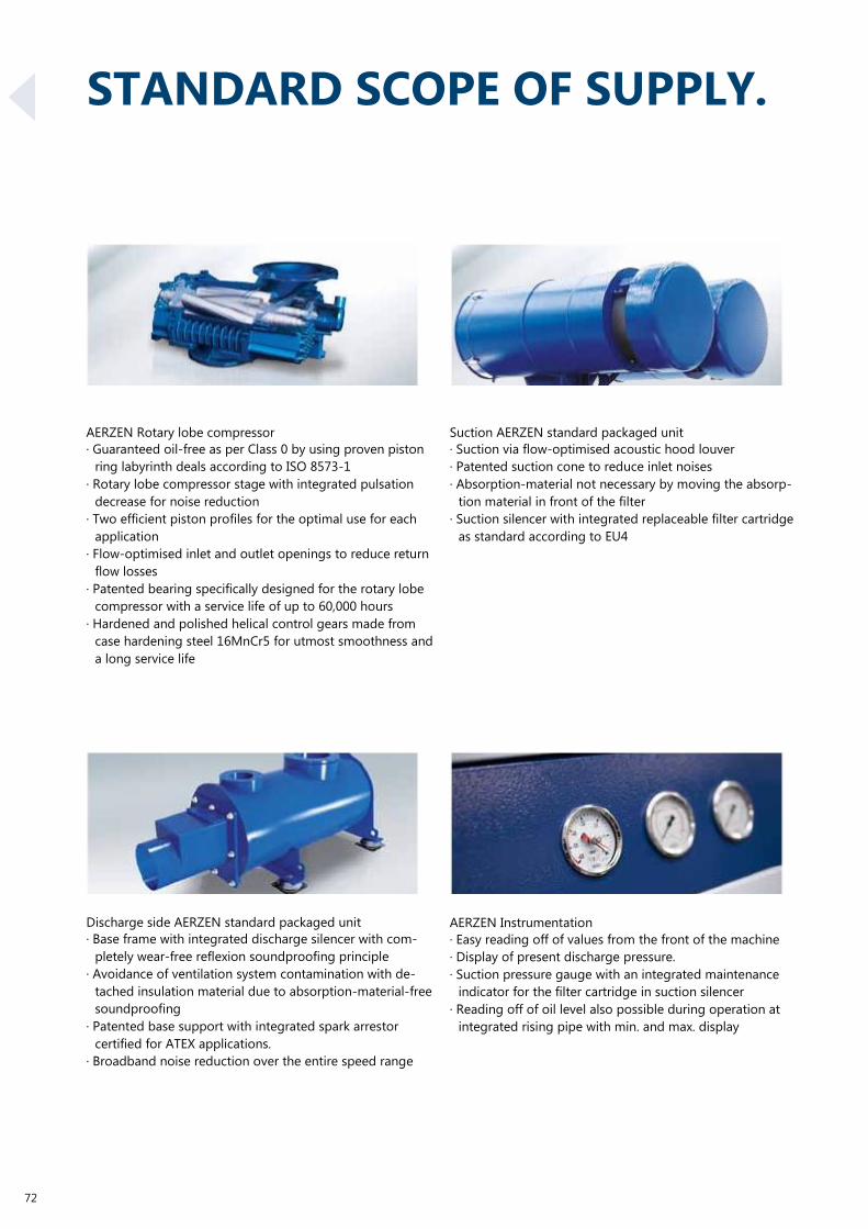
STANDARD SCOPE OF SUPPLY.
72
AERZEN Rotary lobe compressor
· Guaranteed oil-free as per Class 0 by using proven piston
ring labyrinth deals according to ISO 8573-1
· Rotary lobe compressor stage with integrated pulsation
decrease for noise reduction
· Two efficient piston profiles for the optimal use for each
application
· Flow-optimised inlet and outlet openings to reduce return
flow losses
· Patented bearing specifically designed for the rotary lobe
compressor with a service life of up to 60,000 hours
· Hardened and polished helical control gears made from
case hardening steel 16MnCr5 for utmost smoothness and
a long service life
Discharge side AERZEN standard packaged unit
· Base frame with integrated discharge silencer with com-
pletely wear-free reflexion soundproofing principle
· Avoidance of ventilation system contamination with de-
tached insulation material due to absorption-material-free
soundproofing
· Patented base support with integrated spark arrestor
certified for ATEX applications.
· Broadband noise reduction over the entire speed range
Suction AERZEN standard packaged unit
· Suction via flow-optimised acoustic hood louver
· Patented suction cone to reduce inlet noises
· Absorption-material not necessary by moving the absorp-
tion material in front of the filter
· Suction silencer with integrated replaceable filter cartridge
as standard according to EU4 AERZEN Instrumentation
· Easy reading off of values from the front of the machine
· Display of present discharge pressure.
· Suction pressure gauge with an integrated maintenance
indicator for the filter cartridge in suction silencer
· Reading off of oil level also possible during operation at
integrated rising pipe with min. and max. display

AERZEN standard acoustic hood
· Acoustic hood with sound-absorbing foam lining
· Self-supporting acoustic hood construction with transport
openings for forklift and lift truck and integrated oil collec-
tion sump
· Space-saving side-by-side installation.
· Maintenance flaps on the front and back side for easy
maintenance and revision
· oil level can be read off from the front during operation
· UV-resistant and durable powder coating in several layers
· Fresh air suction from the front side of the packaged unit
AERZEN Hinged motor mounting plate
· Base frame with integrated, self-tensioning hinged motor
mounting plate
AERZEN belt drive
· Fully automatic and maintenance-free belt tension
· Belt drive adapted perfectly to the required volume flow
· Simple service and replacement of V-belt.
· Integrated overload protection due to load-transmitting
V-belt
AERZEN Machinery mounting
· Reduction of noise emissions through the floor due to
assembly on flexible machinery mounting
· Aligning of the packaged unit is made easier by the
machinery mounting
73
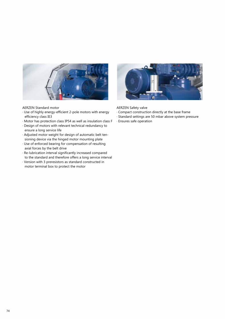
74
AERZEN Standard motor
· Use of highly energy-efficient 2-pole motors with energy
efficiency class IE3
· Motor has protection class IP54 as well as insulation class F
· Design of motors with relevant technical redundancy to
ensure a long service life
· Adjusted motor weight for design of automatic belt ten-
sioning device via the hinged motor mounting plate
· Use of enforced bearing for compensation of resulting
axial forces by the belt drive
· Re-lubrication interval significantly increased compared
to the standard and therefore offers a long service interval
· Version with 3 preresistors as standard constructed in
motor terminal box to protect the motor
AERZEN Safety valve
· Compact construction directly at the base frame
· Standard settings are 50 mbar above system pressure
· Ensures safe operation

75

PERFORMANCE DESCRIPTION OVERPRESSURE. DELTA HyBRID - DESIGN S/L
Pos. 1) Rotary lobe Compressor
To be supplied as complete compact packaged unit ready for connection with all accessories necessary for safe operation.
For the delivery of completely pure process air, oil-free acc. to ISO 8573-1 Class 0 with TÜV certificate and on the discharge side a
sound reduction without any absorption material to ensure the quality of air.
Packaged unit with CE-standard marks and documentation, complying with the regulations of the following guidelines:
· Machine Directive 2006/42/EC
· Electromagnetic Compatibility 2004/108/EC
· Pressure Equipment Directive 97/23/EC
· Protection objectives of the low-voltage directive acc. to enclosure 1, no. 1.5.1.
Make:
Type:
Aerzener Maschinenfabrik
Delta Hybrid
Description of the stage
· Rotary lobe compressor stage for oil-free conveying acc. to Class 0 (ISo 8573-1) and compression of air, performance-optimized
positive displacement machine with minimum flow losses
optionally
or
with twisted rotary pistons (3+3) and patented volumetric efficiency increase, type D 17 L up to D 75 L
with low-pressure rotor profile (3+4) and internal compression, type D 12 S up to D 152 S
·
Housing parts out of EN-GJL-250, rotary pistons and shafts statically and dynamically balanced
·
·
Stage D 17 L up to D 75 L:
Stage D 12 S up to D 152 S:
rotary pistons and shafts made of tempering steel C45N
rotors and shafts out of tempering steel C45N
·
·
·
Gear wheels helically geared, hardened and ground, fixing onto the shafts by means of conical press-on taper
Bearings of the shafts in amply dimensioned roller bearings
oil splash lubrication with additional oil throwers (D 75 L and D 62 S) resp. integrated oil supply (D 17 L up to D 46 L and D 12 S,
D 24 S, D 36 S, D 98 S, D 152 S) by mechanically driven oil pump, oil overflow valve and oil filter
· Sealing of the conveying chamber by spring-sealing disc seals with neutral chamber and oil return thread, sealing of the driving
shaft by tip seal.
Packaged unit description
· The stage is mounted on a torsion-resistant base support in which the discharge silencer is integrated.
· Structure-borne noise- and vibration dampening mounting of the packaged unit on flexible machine feet.
· The discharge silencer is designed, manufactured and tested acc. to the current pressure device guideline PED 97/23/EC (AD 2000).
Supply with CE marks and corresponding documentation. The broadband sound reduction covering the whole speed range is ef-
fected by metallic completely wear-free silencer installations without using absorption materials. On this way, a completely sound
reducing effect is given for the total period of use.
· Narrow V-belt drive, belt guard (packaged unit without acoustic hood)
· Hinged motor mounting plate as tensioning device for belt drive, the automatic belt re-tensioning is effected by the motor weight
exclusively.
· The filter silencer is directly flanged onto the suction socket of the blower. For maintenance purposes the housing is provided with
a detachable cover so that the filter element can be easily removed. The absorption material is located upstream of filter element
viewed from direction of flow.
· The temperature-resistant check valve (shaft-borne) is integrated in the connection housing so that the flap insert can be checked
easy to maintain from outside, without disassembly of the housing.
· The pressure valve for fuse protection of the packaged unit is designed as equipment part with safety function acc. to pressure
device guideline PED 97/23/EC.
· Connection of the pressure piping by flexible connection with hose clamps at the rear front side.
· Main maintenance side: Front side
· A service kit with initial oil filling, oil filling funnel, hinged motor mounting plate, oil drain hose is part of the delivery.
76

Performance data
Conveyed medium atmosph. air
Intake volume flow
Volume flow handled at normal condition
Intake pressure (abs.)
Pressure increase
Intake temperature
Relative air humidity
Discharge temperature
Motor speed
Compressor shaft power
Motor rating
m³/min
Nm³/h
bar
bar
°C
%
°C
1/min
kW
kW
:
:
:
:
:
:
:
:
:
:
.....................................................................................................
.....................................................................................................
.....................................................................................................
.....................................................................................................
.....................................................................................................
.....................................................................................................
.....................................................................................................
.....................................................................................................
.....................................................................................................
.....................................................................................................
(Dimensional tolerance on intake volume and coupling power: ± 5 %)
Options
· Drive with constant speed
· Drive via pole-changing motor
· Drive via frequency converter
· Suction via filter
· Suction via piping, filter with flexible pipe connection (ISO) provided for suction piping.
Selected size:
Connection pressure piping:
D 17 L up to D 75 L or D 12 S up to D 152 S Delta Hybrid
DN ...................................................................
Connection suction piping:
(option)
Driving motor
DN ...................................................................
only for suction via piping
· Motor acc. to IEC standard, type of construction IM B3, type of protection IP 55 -
-
-
-
-
-
Efficiency class IE 3,
Class of insulation F / used acc. to B,
with 3 PTC resistors for winding monitoring,
with re-lubrication device for bearings from size 160M,
Bearings suitable for belt drive
Motor suitable for operation on frequency converter
·
·
·
·
·
·
Nominal voltage / nominal frequency
Nominal power of motor
Nominal speed of motor
Motor size
Nominal current
Starting current
V / Hz
kW
rpm
A
A
:
:
:
:
:
:
.....................................................................................................
.....................................................................................................
.....................................................................................................
.....................................................................................................
.....................................................................................................
.....................................................................................................
Option
Motor start-up direct star-delta on frequency converter
soft starting
77

Start unloading device
· Pneumatically acting start unloading device Aeromat, required for star-delta starting of the motor, mounted on packaged unit
· Additional solenoid valve standard 24 V DC (de-energized closed; other voltage available) mounted on start unloading device, for
star-delta starting of pole-changing motors (option)
Instrumentation
· Pressure gauge for discharge pressure with glycerine filling ø 63 mm, mounted on packaged unit or installed in front of acoustic
hood wall
· Maintenance indicator for filter contamination ø 63 mm, mounted on packaged unit or installed in front of acoustic hood wall
· Pressure gauge for oil pressure with glycerine filling ø 63 mm, mounted on packaged unit or installed in front of acoustic hood wall
for types D 17 L up to D 46 L and D 12 S, D 24 S, D 36 S, D 98 S and D 152 S
· oil pressure switch with types D 17 L up to D 46 L and D 12 S, D 24 S, D 36 S, D 98 S and D 152 S
Options
·
·
·
Intake pressure switch for filter monitoring
Discharge pressure switch
Contact thermometer discharge temperature with capillary line
Instruments mounted on packaged unit, incl. impulse lines,
transmission of a potential-free contact to control at site, switch wired on clamp
Packaged unit weight:
Approx.
...........................
kg
Finish: Manufacturer standard, colour RAL 5001
Supply completely
Pc. ..............
.............................. EUR / piece
.............................. EUR / total
Item 2) Acoustic hood
for rotary lobe compressor ....................... ......................... Delta Hybrid
·
·
·
Acoustic hood made of galvanized steel with oil drip pan and finishing coat
Transport of the acoustic hood possible by fork lift truck
Segmental design with internal lining to reduce the sound pressure level of the machine noise
from
................... dB(A)
to
.................... dB(A) (level with sound-insulated piping)
(Sound level in 1 m distance from the outline of the packaged unit in the free field, sound measurement acc. to DIN 45 635, DIN EN ISO 3744
and DIN EN ISO 2151)
Acoustic hood ventilation
Electrically driven fan (400 V / 50 c/s)
Supply air openings:
Exhaust air openings:
Main operation and maintenance side:
Rear face:
front on the cold side of the packaged unit
rear on the hot side of the packaged unit
front face with detachable, ample segments
with removable segment for user-friendly accessibility to the pressure valve and start
unloading device
78
·
·
·
·
·
·
oil level control indicator integrated outside into acoustic hood front (main operating side)
The oil level control can be effected from outside without opening the acoustic hood with running rotary lobe compressor
oil filling and -draining is simply carried out via the integrated filling reservoir
The oil system is tubed ready for operation
Acoustic hood designed for arrangement of several packaged units side-by-side
Main maintenance side: Front side

A terminal box is integrated in the acoustic hood rear side, in which the power supply unit (standard 400-500 V 50/60c/s) is for the
elctric oil demister, AERtronic (option 3). If round instruments were selected, then all pressure switches / temperature switches (as
far as selected) are installed potential-free on terminal.
Option
·
·
Acoustic hood for indoor installation
Acoustic hood for outdoor installation
Weight of the hood:
Approx.
..........................
kg
Finish: Manufacturer’s standard, colour RAL 5001 / front elements RAL 7047, powder coating
Supply completely
Pc.
.............. .............................. EUR / piece
.............................. EUR / total
Item 3) Option: AERZEN blower control AERtronic
The packed unit is equipped with the operation- and control device performing the following tasks:
· Control of a power control cabinet (star-delta-switching, direct operation or frequency converter) provided by customer
· Monitoring of the limiting values of the rotary lobe compressor
· Recording, visualization and storing of the measured data
· Counting of the operation and service hours
· output and recording of events
AERZEN control unit AS300B AERtronic
· for operation / monitoring of a rotary lobe compressor and the control of a power cabinet provided by customer or as option.
· Visualization and recording of operation data,
· Provision of service, error and maintenance information, navigation and operation via touch screen.
· Working hour meter, monitoring of winding temperature of the driving motor as well as monitoring of intake pressure (filter con-
tamination), discharge pressure, oil pressure and discharge temperature.
· Basic module and extension modules with digital and analogue inputs / outputs
Included are:
· Transmitter for suction pressure, discharge pressure, oil pressure
· Sensors for discharge temperature and oil temperature
· Supply voltage 400 -500V 50/60 c/s
Power supply panel:
Not included, customer’s scope of supply
Pc.
.............. .............................. EUR / piece
.............................. EUR / total
Options
·
·
Extension with Frequncey converter module, signal 4 – 20 mA
Extension with interface module RS 485 (2-wire) for the connection with Profibus-DP (surcharge)
79

PERFORMANCE SPECIFICATION OVERPRESSURE. DELTA HyBRID - DESIGN H
Item 1) Rotary lobe compressor
To be delivered as complete compact unit ready to be connected with all additional parts required for safe operation. For conveying
completely pure process air, oil-free operation, TÜV-certified according to ISO 8573-1 of Class 0 and on the process side absolutely
absorption-material-free soundproofing, to secure the air quality.
Packaged unit with CE label and documentation, conforms with regulations of the following guidelines:
·
·
·
·
Machinery Directive 2006/42/EC
Electromagnetic Compatibility 2004/108/EC
Pressure Equipment Directive 97/23/EC
Protective regulations of the Low Voltage Directive in accordance with Appendix I, No. 1.5.1
Make:
Type:
Aerzener Maschinenfabrik
Delta Blower Generation 5
Description of stage
· Rotary lobe compressor stage for oil-free conveying of Class 0 (ISo 8573-1) and compression of air, performance-optimised dis-
placement units with minimal flow losses with low pressure rotor profile (3+4) and interior compression, Type D 12 H to D 98 H
· Housing parts from EN-GJL-250, rotary pistons and shafts statically and dynamically balanced
· Stage D 12 H to D 98 H: Rotors and shafts made from tempered steel C45N
· Helical gears, hardened and polished, mounted onto the shafts with taper interference fit
· Mounting of shafts in generously dimensioned anti-friction bearings
· oil splash lubrication with additional oil throwers (D 62 H) or integrated oil supply (D 12 H to D 36 H and D 98 H) using mechani-
cally driven oil pump, oil overflow valve and oil filter
· Sealing off of conveying chamber using spring seal washers with neutral space and oil return windings, sealing off of drive shaft
with tip sealing technology
Unit description
· The stage is mounted to a torsion-resistant base frame with an integrated pressure silencer.
· Construction of the unit on flexible machinery mounting which absorbs structural and vibration noises.
· The pressure silencer is constructed, manufactured and tested using the current guidelines of the Pressure Equipment Directive
PED 97/23/EG (AD 2000). Supplied with CE label and relevant documentation. The broadband noise reduction over the entire speed
range is achieved without the use of absorption materials by using metal, completely wear-free sound silencer units. A complete
soundproofing effect is given over the entire usage period.
· Narrow V-belt drive, belt guard (unit without acoustic hood)
· Hinged motor mounting plate as tensioning device for belt drive, the automatic tensioning of the belt occurs through the weight
of the motor alone
· The filter silencer is flanged directly onto the inlet socket of the blower. The housing is fitted with a removable lid for maintenance
purposes so that the filter element can be removed easily. The absorption material is positioned in front of the filter element when
considering the flow direction
· The temperature-resistant check valve (on shaft bearing) is integrated into the connection enclosure so that the flap insert can be
checked easily from the outside without dismantling the housing.
· The pressure valve to secure the unit is constructed as an equipment part with safety function according to the Pressure Equip-
ment Directive PED 97/23/EG.
· Flexible connection of pressure pipelines using flange compensators at the rear front side
· Main maintenance side: Front side
· A service package with first oil fill, oil fill funnel, lifter for hinged motor mounting plate, oil drain hose is part of the delivery scope
80

Performance data
Conveyed medium atmosph. air
Intake volume flow
Volume flow in standard condition
Intake pressure (abs.)
Pressure increase
Intake temperature
Relative humidity
Discharge temperature
Motor speed
Compressor shaft power
Motor rating
m³/min
Nm³/h
bar
bar
°C
%
°C
1/min
kW
kW
:
:
:
:
:
:
:
:
:
:
.....................................................................................................
.....................................................................................................
.....................................................................................................
.....................................................................................................
.....................................................................................................
.....................................................................................................
.....................................................................................................
.....................................................................................................
.....................................................................................................
.....................................................................................................
(Building tolerance for intake volume flow and coupling power: ± 5 %)
Selection positions
· Drive with constant speed
· Drive via pole-changeable motor
· Drive via frequency converter
· Suction via filter
· Suction via pipeline, filter with flex. pipe connection (ISo) intended for suction pipeline
Selected size:
Connection pressure pipeline:
Selection position
D 12 H bis D 98 H Delta Hybrid
DN ...................................................................
Connection suction pipeline:
Drive motor
DN ................................................................... only for suction via pipeline
· Motor according to IEC norm, construction type IM B3, protection class IP 55 -
-
-
-
-
-
Efficiency class IE 3,
Insulation class F/used acc. to B,
with 3 PTC resistor sensors for monitoring the winding,
with re-lubrication device for bearing,
Bearing suitable for belt drive.
Motor suitable for operation at frequency converter.
·
·
·
·
·
·
Nominal voltage / nominal frequency
Motor nominal power
Motor nominal speed
Motor size
Nominal current
Starting current
V / Hz
kW
1/min
A
A
:
:
:
:
:
:
.....................................................................................................
.....................................................................................................
.....................................................................................................
.....................................................................................................
.....................................................................................................
.....................................................................................................
Selection position
Motor start-up direct star-delta at frequency converter
soft start
81

Start unloading device
· Pneumatic start-up unloading valve Aeromat, which is necessary for star-delta starting of the motor, is mounted to the packaged
unit
Selection position
· Additional solenoid valve 230 V / 50 Hz (closed when current less) is mounted to the start-unloading, for star-delta starting of
pole-changeable motors
· Solenoid valve 230 V / 50 Hz (closed when current less) as start-unloading. only for unit nominal size DN 50, blower GM 3S
Unit: ..............
Unit weight:
Paint:
Deliver completely units
.............................. EUR / unit
.............................. EUR / Total
approx. ............... kg
Manufacturer standard, colour RAL 5001
.............................. EUR / unit
.............................. EUR / Total
Instrumentation (AERZEN Blower controls AERtronic)
The unit is equipped with the operating and control device AERtronic, which takes on the following tasks:
·
·
·
·
·
Control of the client’s power switch cabinet (star-delta circuit, direct operation or frequency converter)
Monitor limit values of the rotary lobe compressor
Capture, visualise and save measurement data
Count operating and service hours
Issue and log events
AERZEN control unit AS300B AERtronic
· For the operation/monitoring of a rotary lobe compressor and the control of the client’s own or optional power cabinet
· Visualisation and saving of operating data,
· Provision of service, error and maintenance information, navigation and operation via TouchScreen.
· operating hour counter, monitoring of winding temperature of drive motor as well as monitoring of intake pressure (filter pollu-
tion), discharge pressure, oil pressure as well as discharge temperature
· Basic module and extension modules with digital and analogue inlets/outlets.
Contained within:
· Transmitter for suction pressure, discharge pressure, oil pressure
· Sensors for discharge temperature and oil temperature
· Resistance thermometer PT 1000 to monitor the oil temperature
· Supply voltage 400-500 V 50/60Hz
Power supply panel: not included, must be supplied by client
Selection position
· Extension with interface module RS 485 (2-wire) for the connection with the Profibus-DP (additional cost)
Item 2) Acoustic hood
for the rotary lobe compressor ....................... ......................... Delta Hybrid
·
·
·
Acoustic hood made from galvanised steel sheets with oil collecting sump and topcoat
Acoustic hood suitable for transport with fork lift
Segment design with interior lining to reduce machine noise pressure level
from
................... dB(A)
to
.................... dB(A) (Level with soundproof pipelines)
(noise level in 1 m distance from unit outline in free field, noise measurements according to DIN 45 635, DIN EN ISO 3744 and DIN EN ISO 2151)
82

Acoustic hood ventilation
Electrically driven fan ( 400 V 50 Hz )
Supply air openings:
Exhaust air openings:
at the front on the cold side of the unit
at the rear on the warm side of the unit
Main operating and maintenance side: anterior front side with removable, generous segments
Posterior front side:
with removable segment for user-friendly accessibility to pressure valve
and start unloading device
·
·
·
·
oil level control display integrated outside of the front of the acoustic hood (main operating side)
The oil level can be checked from the outside without opening the acoustic hood when the rotary lobe compressor is running
oil can be filled up or drained simply via the integrated fill-up tank
The oil system is ready to use complete with piping
· Acoustic hood designed for construction of several units directly next to each other
· Main maintenance side: Front side
A terminal box is integrated into the rear wall of the acoustic hood into which the power supply unit (standard 400-500 V 50/60Hz)
for oil demisting, AERtronic (Selection position 3) is integrated
Selection position
· Acoustic hood for indoor installation
· Acoustic hood for outdoor installation
Hood weight:
approx.
...........................
kg
Paint: Manufacturer standard, colour RAL 5001 / front elements RAL 7047, powder painting
delivery completely
unit
.............. .............................. EUR / unit
.............................. EUR / Total
83

MAINTENANCE AND REVISION.
The following table describes the standard maintenance for AERZEN rotary lobe compressor: Delta
Hybrid.
Maintenance for 1 year
Amount
1
Maintenance for 2 years
Amount
2
1
1
1
Maintenance for 5 years
Amount
4
2
2
2
Revision
Amount
1
Maintenance part
Replace intake filter
Maintenance part
Replace intake filter
Replace V-belt
Replace lubrication oil DELTA LUBE 06
Replace oil filter
Maintenance part
Replace intake filter
Replace V-belt
Replace lubrication oil DELTA LUBE 06
Replace oil filter
Revision part
Exchange after completely revised
Interval
After 8000 Oh or annually
Interval
After 8000 Oh or annually
After 16000 Oh or after 2 years
After 16000 Oh or after 2 years
After 16000 Oh or after 2 years
Interval
After 8000 Oh or annually
After 16000 Oh or after 2 years
After 16000 Oh or after 2 years
After 16000 Oh or after 2 years
Interval
After 40000 Oh or after 5 years
compressor stage
Oh = operating hours
Note: All intervals specified are manufacturer’s
recommendations.
84

85

10
1 5
00
31
2
1 0
5
1 0
40
TECHNICAL DRAWINGS.
DELTA HYBRID D 12 S/H
3140
1210
3451
3410
2410
1210
7220
X
Drehrichtung
4420
Ölstand
oil level
sense of rotation
1810
2710 7220
5310
610
610 611-A 270
215 610 110 452 580
Schaltschrank für Rundinstrumentierung
control box for round instrumentation
B
1250
A
A
90
15
1350
1170
376 10
Kabelzuführung
cable entry
Erdungsanschluß
earth connection
Pos.
Benennung
Description
610
611-A
611-B
1210
1810
2110
2410
2710
2720
3150
Grundträger
Anschlussgehäuse für
Muffe
Anschlissgehäuse mit
Flansch -Option-
Ölnebelabscheider
Motor
Riemenantrieb
Riemenschutz -Option-
Elast. Rohrverbindung DS
-Muffe-
Elast. Rohrverbindung DS
Kompensator -Option-
Schallschluckmatte
-Option-
Base support
Connection housing for sleeve
Connection housing with flange -optional-
Oil demister
Motor
Belt drive
Belt guard -optional-
Flexible pipe connection DS
-sleeve-
Flex. pipe connection DS
compensator -optional-
Noise absorption mat -optional-
3151
3410
3450
4420
5310
6510
6520
6550
6580
7110
7220
7240
Ansaugtopf
Filterschalldämpfer
Elast. Rohrverbindung SS
-Option-
Sicherheitsventil
Anfahrentlastung
Wartungsanzeiger
Manometer
Öldrucküberwachung
AERZEN Steuerung
AERtronic -Option-
Schallhaube
Elektrischer Lüfter
Abdeckbleck -Option-
Suction cup
Filter silencer
Flexible pipe connection SS
-optional-
Safety valve
Start unloadng device
Service indicator
Pressure gauge
Oil pressure control
AERZEN control unit AERtronic
-optional-
Acoustic hood
Electrical fan
Cover plate -optional-
Drawing no.: 4000116536
86

2110
Drehrichtung
sense of rotation
1210
3410
100
2410
611-A
A
A
610
50
160
450
110
182
580
()93
1166
1810
C
C
B
4420
Schaltschrank für Rundinstrumentierung control box for round instrumentation
X
6550
6510
6520
400
160
5
B
Pos.
100
Benennung
Drehkolbenverdichter
Description
Rotary lobe compressor
610
611-A
611-B
1210
1810
1820
2110
2410
2710-A
Grundträger
Anschlussgehäuse für Muffe
Anschlussgehäuse mit
Flansch -Option -
Ölnebelabscheider
Motor
Motorbefestigung
Riemenantrieb
Riemenschutz
Rohrverbindung DS mit
Muffe
Base support
Connection housing for sleeve
Connection housing with flange
-optional-
Oil demister
Motor
Motor connection
Belt drive
Belt guard
Flexible pipe connection DS with
sleeve
2710-B
3410
3450
4420
5310
6510
6520
6550
6580
Rohrverbindung DS mit
Kompensator -Option-
Filterschalldämpfer
Rohrverbindung SS Option-
Sicherheitsventil
Anfahrentlastung -Option-
Wartungsanzeiger
Manometer
Öldruckmanometer
Elektrische Steuerung
AERtronic -Option-
Pipe connection DS with
compensator -optional-
Filter silencer
Pipe connection SS -optional-
Safety valve
Start unloading device -optional-
Service indicator
Pressure gauge
Oil pressure gauge
Electric control AERtronic
-optional-
Drawing no.: 4000129522
87

DELTA HYBRID D 17 L
10
1210
3451
7110
3410
100
2410
1210
220
2110
÷ lstand
oil level
X Drehrichtung
sense of rotation
1 10
4420
7220
2110
610 5310
610
215
61
0
1250
110
27
0
452
5 0
1350
Schaltschrank f¸ r Rundinstrumentierung
control box round instrumentation
1810
A
4420
611-A
15
A
90 1170
Kabelzuf¸ hrung
cable entry
E Erdungsanschlufl
earth connection
375 5 3150
Schallschluckmatte
Noise absorption mat -optional-
Pos.
100
610
611-B
611-A
1210
1810
2110
2410
2710
2720
Benennung
Gebläsestufe
Grundträger
Anschlussgehäuse mit
Flansch -Option-
Anschlussgehäuse mit
Muffe
Ölnebelabscheider
Motor
Riementrieb
Riemenschutz -Option-
Elast. Rohrverbindung DS
-Muffe-
Elast. Rohrverbindung DS-
Kompensator -Option-
Description
Blower stage
Base support
Connection housing with flange
-optional-
Connection housing for sleeve
Oil demister
Motor
Belt drive
Belt guard -optional-
Flex. pipe connection DS -sleeve-
Flex. pipe connection DS -
compensator -option-
3410
3450
3451
4420
5310
6510
6520
6550
6580
7110
7220
7240
-Option-
Filterschalldämpfer
Elastische Rohrverbindung
SS -Option-
Ansaugtopf
Sicherheitsventil
Anfahrentlastung -Option-
Wartungsanzeiger
Manometer
Manometer Öldruck
AERZEN Steuerung
AERtronic -Option-
Schallhaube
Axialventilator
Abdeckblech -Option-
Filter silencer
Flexible pipe connection SS
-optional-
Suction pot
Safety valve
Start unloading device -optional-
Service indicator
Pressure gauge
Pressure gauge oil pressure
AERZEN control unit
AERtronic -optional-
Acoustic hood
Axial fan
Cover plate -optional-
Drawing no.: 4000117603_02
88

Pos.
100
610
611-B
611-A
1210
1810
2110
2410
2710
Benennung
Gebläsestufe
Grundträger
Anschlussgehäuse mit
Flansch -Option-
Anschlussgehäuse mit
Muffe
Ölnebelabscheider
Motor
Riementrieb
Riemenschutz -Option-
Elast. Rohrverbindung DS
Description
Blower stage
Base support
Connection housing with flange
-optional-
Connection housing with sleeve
Oil demister
Motor
Belt drive
Belt guard -optional-
Flex. pipe connection DS -sleeve-
2720
3410
3450
3470
4420
5310
6510
6520
6550
6580
Elast. Rohrverbindung DS-
Kompensator -Option-
Filterschalldämpfer
Elastische Rohrverbindung
SS
Ansaugfilter
Sicherheitsventil
Anfahrentlastung -Option-
Wartungsanzeiger
Manometer
Öldrucküberwachung
AERZEN Steuerung
Flex. pipe connection DS -
compensator -option-
Filter silencer
Flexible pipe connection SS
Intake filter
Safety valve
Start unloading device -optional-
Service indicator
Pressure gauge
Oil pressure control
AERZEN control unit
-Muffe- AERtronic -Option- AERtronic -optional-
Drawing no.: 4900104379
89

DELTA HYBRID D 24 S/H
3410
1210
3451
7110
3410
100
2410
1210
220
÷ lstand
oil level
X
2110
Drehrichtung
sense of rotation
4420
2710
610
1 10
10 7220
2110
5310
10
215
610
1250
110
11
270
452
5 0
1350
chaltschran f¸ r undinstru entierung
control bo round instru entation
A
611-A
Schallhaubenbefestigung
acoustic hood mounting
15
90 1170
Kabelzuf¸ hrung
cable entry
E
Erdungsanschlufl
earth connection
A
375
5
3150
Schallschluckmatte
Absorption mat
Pos. Benennung Description -Option-
100
610
611-B
611-A
1210
1810
1820
2110
2410
2710
2710-B
Verdichterstufe
Grundträger
Anschlussgehäuse mit
Flansch -Option-
Anschlussgehäuse für
Muffe
Ölnebelabscheider
Motor
Motorbefestigung
Riementrieb
Riemenschutz -Option-
Elast. Rohrverbindung DS
Elast. Rohrverbindung DS-
Kompensator -Option-
Compressor stage
Base support
Connection housing with flange
-optional-
Connection housing for sleeve
Oil demister
Motor
Motor fastening
Belt drive
Belt guard -optional-
Flex. pipe connection DS
Flex. pipe connection DS -
compensator -option-
3410
3450
3451
4420
5310
6510
6520
6550
6580
7110
7220
7240
Filterschalldämpfer
Elastische Rohrverbindung
SS -Option-
Ansaugtopf
Sicherheitsventil
Anfahrentlastung -Option-
Wartungsanzeiger
Manometer
Manometer Öldruck
AERZEN Steuerung
AERtronic -Option-
Schallhaube
Axialventilator
Abdeckblech -Option-
Filter silencer
Flexible pipe connection SS
-optional-
Suction pot
Safety valve
Start unloading device -optional-
Service indicator
Pressure gauge
Pressure gauge oil pressure
AERZEN control unit
AERtronic -optional-
Acoustic hood
Axial fan
Cover plate -optional-
Drawing no.: 4000124384
90

3410
1210
6510
6550
6520
3410
100
2110
Drehrichtung
sense of rotation
sense of rotation
4420
611-A
2710
B
s a
non ret rn f a
a e
B
160
450
Schaltschrank f¸ r Rundinstrumentierung
control box round instrumentation
110
Kabelzuf¸ hrung
cable entry main motor
10
1 2
5 0
122
2410
1810
400
160
5
Erdungsanschlufl
earth connection
Pos.
Benennung
Description
100
610
611-B
611-A
1210
1810
1820
2110
2420
2710
Verdichterstufe
Grundträger
Anschlussgehäuse mit
Flansch -Option-
Anschlussgehäuse für
Muffe
Ölnebelabscheider
Motor
Motorbefestigung
Riementrieb
Riemenschutz
Elastische Rohrverbindung
Compressor stage
Base support
connection housing with flange
-optional
connection housing for sleeve
Oil demister
Motor
Motor connection
Belt drive
Belt guard
Flexible pipe connection DS
2720
3410
3450
4420
5310
6510
6520
6550
6580
Elastische Rohrverbindung
DS -Kompensator
Filterschalldämpfer
Elastische Rohrverbin-
dung SS
Sicherheitsventil
Anfahrentlastung -Option-
Wartungsanzeiger
Manometer
Öldruckmanometer
Elektronische Steuerung
(AERtronik) -Option für
Flexible pipe connection DS -com-
pensator
Filter silencer
flexible pipe connection SS
Safety valve
Start unloading device -optional
Service indicator
Acoustic hood
Oil pressure gauge
Electronic control (AERtronic)
-optional for D98S
DS D98S-
Drawing no.: 4000130172
91

1 0
5
31 2
5±
1 0
40
DELTA HYBRID D 28 L
1210
3451 7110 100 2410 1210
7110
Ölstand
oil level
X
2110
Drehrichtung
sense of rotation
4420
610
1810
2710
7110
2110
5310
610
215 610 1250
110 611-A 270
452
580
1350
Schaltschrank für Rundinstrumentierung control box for round instrumentation
Ø 15
A
90
1170
Kabelzuführung cable entry
E
Erdungsanschluß
earth connection
A
375 ± 5
3150
Schallschluckmatte
-Option-
Noise absorption mat -optional-
Pos.
100
610
611-B
611-A
1210
1810
2110
2410
2710
2720
Benennung
Gebläsestufe
Grundträger
Anschlussgehäuse mit
Flansch -Option-
Anschlussgehäuse mit
Muffe
Ölnebelabscheider
Motor
Riementrieb
Riemenschutz -Option-
Elast. Rohrverbindung DS
Elast. Rohrverbindung DS-
Kompensator- Option
Description
Blower stage
Base support
Connection housing with flange
-optional-
Connection housing for sleeve
Oil demister
Motor
Belt drive
Belt guard -optional-
Flex. pipe connection DS
Flex. pipe connection DS -
compensator -option-
3410
3450
3451
4420
5310
6510
6510
6520
6520
6580
7110
7240
Filterschalldämpfer
Elastische Rohrverbindung
SS -Option-
Ansaugtopf
Sicherheitsventil
Anfahrentlastung -Option-
Wartungsanzeiger
Manometer
Manometer Öldruck
AERZEN Steuerung
AERtronic -Option-
Schallhaube
Axialventilator
Abdeckblech -Option-
Filter silencer
Flexible pipe connection SS
-optional-
Suction pot
Safety valve
Start unloading device -optional-
Service indicator
Pressure gauge
Pressure gauge oil pressure
AERZEN control unit
AERtronic -optional-
Acoustic hood
Axial fan
Cover plate -optional-
Drawing no.: 4000124708_01
92

Pos.
100
610
611-B
611-A
1210
1810
2110
2410
2710
Benennung
Gebläsestufe
Grundträger
Anschlussgehäuse mit
Flansch -Option-
Anschlussgehäuse mit
Muffe
Ölnebelabscheider
Motor
Riementrieb
Riemenschutz -Option-
Elast. Rohrverbindung DS
Description
Blower stage
Base support
Connection housing with flange
-optional-
Connection housing for sleeve
Oil demister
Motor
Belt drive
Belt guard -optional-
Flex. pipe connection DS -sleeve-
2720
3410
3450
3470
4420
5310
6510
6520
6550
6580
Elast. Rohrverbindung DS- Kompensator -Option-
Filterschalldämpfer
Elastische Rohrverbindung
SS
Ansaugfilter
Sicherheitsventil
Anfahrentlastung -Option-
Wartungsanzeiger
Manometer
Öldrucküberwachung
AERZEN Steuerung
Flex. pipe connection DS - compensator -option-
Filter silencer
Flexible pipe connection SS
Intake filter
Safety valve
Start unloading device -optional-
Service indicator
Pressure gauge
Oil pressure control
AERZEN control unit
-Muffe- AERtronic -Option- AERtronic -optional-
Drawing no.: 4900104379
93

80
1 98
0
89
0
28
5
357
1 03
57±
10
DELTA HYBRID D 36 S/H
7110
1210
3451
1210
3410
100
2410
3410
X
2110
7220
Drehrichtung
4420
6410
Ölstand
oil level
sense of rotation
611-A
2710-A
Erdungsanschluß
earth connection
11
100
285
610
255 780
1500
7110
561 760
1800
1240
Schaltschrank für Rundinstrumentierung
control box for round instrumentation
Schallhaubenbefestigung
1810
4420
610
acoustic hood mounting
1810
3451
15
Z
A
1472
229
Kabelzuführung
cable entry
Erdungsanschluß
earth connection
A
435±10
Pos.
100
610
611-B
611-A
1210
1810
1820
2110
2410
2710-A
2710-B
Benennung
Drehkolbenverdichter
Grundträger
Anschlussgehäuse mit
Flansch -Option-
Anschlussgehäuse für
Muffe
Ölnebelabscheider
Motor
Motorbefestigung
Riementrieb
Riemenschutz -Option-
Elast. Rohrverbindung DS
-Muffe-
Elast. Rohrverbindung DS-
Kompensator- Option
Description
Rotary lobe compressor
Base support
Connection housing with flange
-optional-
Connection housing for sleeve
Oil demister
Motor
Motor fastening
Belt drive
Belt guard -optional
Flex. pipe connection DS -sleeve-
Flex. pipe connection DS - compensator -option-
3150
3410
3450
3451
4420
6410
6510
6520
6550
6580
7110
7220
7240
Schallschluckmatte -Option-
Filterschalldämpfer
Elastische Rohrverbindung
SS -Option-
Ansaugtopf
Sicherheitsventil
Ölsystem
Wartungsanzeiger
Manometer
Manometer Öldruck
AERZEN Steuerung
AERtronic -Option-
Schallhaube
Axialventilator
Abdeckblech -Option-
Absorption mat
Filter silencer
Flexible pipe connection SS
-optional-
Suction pot
Safety valve
Oil system
Service indicator
Pressure gauge
Pressure gauge oil pressure
AERZEN control unit
AERtronic -optional-
Acoustic hood
Axial fan
Cover plate -optional-
Drawing no.: 4000033613
94

(1 6
7 6
)
1 4
68
1 0±
21 7
1 0±
3410
180
5
1210
1810
1210
1810
C
C
3410
100
4420
2110
2410
Ölstand
oil level
Drehrichtung
sense of rotation
1820 B 610
2410
610
425 180 ± 5
116 88 780 Erdungsanschluß
earth connection
B
1445
3451
3410
6510
6520
6550
(1734)
195
1210
4420
611-A
2710-A
A
A
100
2410
610
Schaltschrank für Rundinstrumentierung
control box for round instrumentation
276
760
(247)
Erdungsanschluß
459 2410 1810 610
earth connection
Pos.
100
610
611-A
611-B
1210
1810
1820
2110
2420
2710-A
Benennung
Drehkolbenverdichter
Grundträger
Anschlussgehäuse für
Muffe
Anschlussgehäuse mit
Flansch -Option für D98S-
Ölnebelabscheider
Motor
Motorbefestigung
Riementrieb
Riemenschutz
Rohrverbindung DS mit
Description
Rotary lobe compressor
Base support
Connection housing for sleeve
Connection housing with flange -optional for D98S611-
Oil demister
Motor
Motor fastening
Belt drive
Belt guard
Pipe connection DS with sleeve
2710-B
3410
3450
3451
4420
5310
6510
6520
6550
6580
Rohrverbindung
DS mit Kompensator
-Option für D98S-
Filterschalldämpfer
Rohranschluss SS -Option-
Ansaugtopf -Option-
Sicherheitsventil
Anfahrentlastung -Option-
Wartungsanzeiger
Manometer
Öldruckmanometer
Elektronische Steuerung
(AERtronic) -Option für
Pipe connection DS with compen-
sator -optional for D98S-
Filter silencer
Pipe connection SS -optional-
Suction pot -optional-
Safety valve
Start unloading device -optional-
Service indicator
Pressure gauge
Oil pressure gauge
Electronic control (AERtronic)
-optional for D98S-
Muffe D98S-
Drawing no.: 4000074127
95

80
890
1 9
80
285
35
7
10
DELTA HYBRID D 46 L
7110
1210
3451
1210
3410
100
2410
3410
7220
Ölstand
oil level
X
Drehrichtung
sense of rotation
4420
611-A
2110
6410
2710-A
610
11
255
780
1500
Erdungsanschluss
earth connention
100
285
Schaltschrank für Rundinstrumentierung
control box for round instrumentation
7110
561 760
1800
1240
4420
Schallhaubenbefestigung
acoustic hood mounting
1810
15
1810 A
610
3451
Z
A
1472
1506
229
Kabelzuführung
cable entry
Erdungsanschluss
earth connection
435 10 3150
Schallschluckmatte
Absorption mat
Pos.
100
610
611-B
611-A
1210
1810
2110
2410
2710-A
2710-B
Benennung
Drehkolbenverdichter
Grundträger
Anschlussgehäuse mit
Flansch -Option-
Anschlussgehäuse für
Muffe
Ölnebelabscheider
Motor
Riementrieb
Riemenschutz -Option-
Elast. Rohrverbindung DS
-Muffe-
Elast. Rohrverbindung DS-
Kompensator- Option
Description
Rotary lobe compressor
Base support
Connection housing with flange
-optional-
Connection housing for sleeve
Oil demister
Motor
Belt drive
Belt guard -optional
Flex. pipe connection DS -sleeve-
Flex. pipe connection DS -
compensator -option-
3410
3450
3451
4420
6410
6510
6520
6550
6580
7110
7220
7240
-Option-
Filterschalldämpfer
Elastische Rohrverbindung
SS -Option-
Ansaugtopf
Sicherheitsventil
Ölsystem
Wartungsanzeiger
Manometer
Manometer Öldruck
AERZEN Steuerung
AERtronic -Option-
Schallhaube
Axialventilator
Abdeckblech -Option-
Filter silencer
Flexible pipe connection SS
-optional-
Suction pot
Safety valve
Oil system
Service indicator
Pressure gauge
Pressure gauge oil pressure
AERZEN control unit
AERtronic -optional-
Acoustic hood
Axial fan
Cover plate -optional-
Drawing no.: 4000099934
96

2410
2710
2720
Riemenschutz
Elast. Rohrverbindung DS
Elast. Rohrverbindung DS
Belt guard
Flex. pipe connection
Flex. pipe connection DS -optional-
Pos. Benennung Description -Zubehör-
100
610
611
613
620
1210
1810
2110
Gebläsestufe
Grundträger
Anschlussgehäuse
Elastischer Maschinenfuß
Motorwippe
Ölnebelabschneider für
Ölraumentlastung
Motor
Riementrieb
Blower stage
Base support
Connection housing
Flex. machinery mounting
Hinged motor mounting plate
Oildemister for oil chamber relief
Motor
Belt drive
3410
3470
4420
5310
6510
6520
6550
6580
Filterschalldämpfer
Ansaugfilter
Sicherheitsventil
Anfahrentlastung -Option-
Wartungsanzeiger
Manometer
Öldrucküberwachung
AERZEN Steuerung
-Option-
Filter silencer
Intake filter
Safety valve
Start unloading device -optional-
Service indicator
Pressure gauge
Oil pressure control
AERZEN control -optional-
Drawing no.: 4900104391
97

80
890
1595±
10
1
980
35
7
1 0357±
10
285
DELTA HYBRID D 52 S
1210
3451
3410
100
110
410
410
44 0
7220
X
Drehrichtung
sense of rotation
10
Ölstand
oil level
1820
11
10
Ø 11
100
255
Schaltschrank für Rundinstumentierung
control box for round instumentation
780 1500
5 1800
0 1240
230
Schallhaubenbefestigung
acoustic hood mounting
1810
A
Z
A
1472
229
Kabelzuführung
cable entry
Erdungsanschluss
earth connection
435±10
Pos.
100
610
611-B
611-A
1210
1810
1820
2110
2410
2710
2720
Benennung
Drehkolbenverdichter
Grundträger
Anschlussgehäuse mit
Flansch -Option-
Anschlussgehäuse für
Muffe
Ölnebelabscheider
Motor
Motorbefestigung
Riementrieb
Riemenschutz -Option-
Elast. Rohrverbindung DS
-Muffe-
Elast. Rohrverbindung DS-
Kompensator- Option
Description
Rotary lobe compressor
Base support
Connection housing with flange
-optional-
Connection housing for sleeve
Oil demister
Motor
Motor fastening
Belt drive
Belt guard -optional
Flex. pipe connection DS -sleeve-
Flex. pipe connection DS -compen- sator -option-
3150
3410
3450
3451
4420
6410
6510
6520
6550
6580
7110
7220
7240
Schallschluckmatte
-Option-
Filterschalldämpfer
Elastische Rohrverbindung
SS -Option-
Ansaugtopf
Sicherheitsventil
Ölsystem
Wartungsanzeiger
Manometer
Manometer Öldruck
AERZEN Steuerung
AERtronic -Option-
Schallhaube
Axialventilator
Abdeckblech -Option-
Absorption mat
Filter silencer
Flexible pipe connection SS
-optional-
Suction pot
Safety valve
Oil system
Service indicator
Pressure gauge
Pressure gauge oil pressure
AERZEN control unit
AERtronic -optional-
Acoustic hood
Axial fan
Cover plate -optional-
Drawing no.: 4000216343
98

16
8,3
Ø
(DN
15
0)
2710
150
611-A
3150
611-B
10
Rückschlagklappe
Check valve
2720
120 Rückschlagklappe
Check valve
DN150 PN10
86 10 286
6580
2410
230
117± 10
6580
286
6510
6520
6550
99

2111
357±5
357
125
(282)
1268
52
150
31855-Aerzen-Germ any
1 : 10
Achtung!
Delta Hybrid
DN200 15. 01. 2 01 4 WAL LB AUM_H
D 62 S 22.01.2014 SEE DOR FF_ S
DELTA HYBRID D 62 S/H
1
2
3
4
5
6
7
8
9
10
11
12
13
14
15
16
A 3410 6511 1210 6510 6520 2110 3410 2110 7110 A
B
C
Drehrich tung
sense of rota tion
4420
1810
Schaltschrank
control box
4420
B
C
D
Ölstand
oil level
D
610
1810 A
E 610
X
E
F
140
345
291
600
780
3 3 1
(575)
(338)
811
760
(484)
(60)
Kabelzuführung
cable entry
Erdungsanschluß
earth connection
525±5
F
G
1700
A(1:5) Rückschlagklappe
non return flap
183
Erdungsanschluß
earth connection
2055 G
1810
618 1088 (349)
H
1210
14 H
87 5
J J
K
X(1:5)
32
64
2110
7110
Schallhaube
acoustic hood
K
6520 Manometer pressure gauge
44
6511
6510
4420
3410
2110
1810
Druckschalter Saugseite
Wartungsanzeiger
Sicherheitsventil
Filterschalldämpfer
Riementrieb
Motor
pressure switch suction side
service indicator
pressure valve
filter silencer
belt d rive
motor
L 31 1 12 65 276 1538 (241)
1210
610
Pos
Öln eb elab schei de r
Grun dträ g er Beschreibung
oil seperator
base frame descrip tion
L
M
3410 freiraum für Wartungsarbei ten S tirnseitig min . 800mm
free space for main tenance work at front side of unit 800mm min.
A erzen er
M a sch in e n fa b r ik G m b H
AERZEN
0 2 1 5. 0 1. 1 4 W A L L B
0 1 1 9. 1 2. 1 3 S E E D O
V s Ä- Nr . Da tu m Na m e
Ä nderungs-Nr:
Alte Do ku m e n t- Nr :
A l lge m eint o le r an z e n: M a ß st ab:
IS O 2 76 8 -m H
IS O 1 39 20
IS O 8 01 5
S ch u t z ve r m e r k n a ch I S O 1 6 0 1 6 K o p i e m u s s n ic h t m a ß st ä b l i ch se in !
Inventor - Zeichnung Ä n de r un g nu r m i tt e l s In v en to r !
D atu m Na m e
E rste l l t
durch:
Genehm igt
von:
4000070552 000
D o ku m en te nt y p:
Aggregatszeichnung
Do kum en ten sta tu s: L abo r /Bür o :
Fert. Freigabe 110
Ve r sio n Fo r m a t Sp r a ch e Bla t t
02 A1 DE 1
M
1 2 3 4 5 6 7 8 9 10 11 12 13 14 15 16
100
Drawing no.: 4000070552
Pos.
610
1210
1810
2110
3410
4420
6510
6511
6520
7110
Benennung
Grundträger
Ölnebelabscheider
Motor
Riementrieb
Filterschalldämpfer
Sicherheitsventil
Wartungsanzeiger
Druckschalter Saugseite
Manometer
Schallhaube
Description
Base support
Oil demister
Motor
Belt drive
Filter silencer
Safety valve
Service indicator
Pressure switch suction side
Pressure gauge
Acoustic hood

1 5
90
(D N
200)
1 8
55
3410
6510
6520
4420
1210
2110
Drehrichtung
sense of rotation
F
G
610 213
F(1:5)
780
1466
Ölstand
oil level
3410
2420
1210
1810
2420
Rückschlagklappe
E
D
610
D
Erdungsanschluß 760 233
earth connection
983,5
3410
Pos.
610
1210
1810
2110
2420
3410
4420
6510
6520
Benennung
Grundträger
Ölnebelabscheider
Motor
Riementrieb
Riemenschutz
Filterschalldämpfer
Sicherheitsventil
Wartungsanzeiger
Manometer
Description
Base support
Oil demister
Motor
Belt drive
Belt guard
Filter silencer
Safety valve
Service indicator
Pressure gauge
Drawing no.: 4000108051
101

55
320
1 4
58
2345
10
456
(1 2
2)
DELTA HYBRID D 75 L
3410
1210
3410
100
2410 optional
7220
Ölstand
oil level
X
Drehrichtung
sense of rotation
4450
4420
2110 611 7275
7275
610
1810
1820
2150
2710 2110
610
11
284 950 (666)
1900 Erdungsanschluß
earth connection
26
769 950 (481)
Die Hebevorrichtung ist nach Betriebsanleitung (G4-079) einzustellen!
The lifting devise must be adjusted to the operating instruktions (G4-079)
2200
7110
Schallhaubenbefestigung
acoustic hood mounting
331
14
1538
1810
2110
(331)
2410 optional
Schaltschrank
4420 control box
100
1810
A
1820
Y
331
3410
1653
(216)
Kabelzuführung
cable entry
773 Erdungsanschluß
earth connection
A 594
10
3410
Filterschalldämpfer
filter silencer
Pos.
100
610
611
611
1210
1810
1820
2110
2150
2410
2710
2720
Benennung
Drehkolbenverdichter
Grundträger
Anschlussgehäuse für Muffe
Anschlussgehäuse mit Flansch
Ölnebelabscheider
Motor
Motorbefestigung
Riementrieb
Hebevorrichtung
Riemenschutz -option-
Elastische Rohrverbindung DS
(Muffe)
Elastische Rohrverbindung DS
(Kompensator) -Option-
Description
Rotary lobe compressor
Base support
Connection housing for sleeve
Connection housing with flange
Oil mist demister
Motor
Motor fastening
Belt drive
Lifting device
Belt guard -optional-
Flexible pipe connection DS
(sleeve)
Flexible pipe connection DS
(compensator) -optional-
3450
4420
4450
5310
6510
6520
6530
6580
7110
7220
7240
7275
Elastische Rohrverbindung SS
(Muffe) -Option-
Ventil
Rohrverbindung für Ventil
Anfahrentlastung -Option-
Wartungsanzeiger
Manometer
Thermometer -Option-
AERZEN Steuerung (AERtro-
nik) -Option-
Schallhaube
Axialventilator
Abdeckblech -Option-
Ölstandanzeiger
flexible pipe connection SS
(sleeve) -optional-
Valve
Pipe connection for valve
Start unloading device (soft start)
-optional-
Service indicator
Pressure gauge
Thermometer -optional-
AERZEN control unit (AERtronic)
-optional-
Acoustic hood
Axial fan
Cover plate -optional-
Oil level indicator
Drawing no.: 4000124319
102

Pos.
100
610
611
613
620
1810
2410
2420
2710
3410
3450
4420
5310
6510
6520
6580
Benennung
Gebläsestufe
Grundträger
Anschlussgehäuse
Elastischer Maschinenfuß
Motorwippe
Motor
Handschutz
Riemenschutz
Elast. Rohrverbindung DS
Filterschalldämpfer
Elast. Rohrverbindung SS
Sicherheitsventil
Anfahrentlastung -Option-
Wartungsanzeiger
Manometer
AERZEN Steuerung
Description
Blower stage
Base support
Connection housing
Flex. machinery mounting
Hinged motor mounting plate
Motor
Hand guard
Belt guard
Flex. pipe connection
Filter silencer
Flex. pipe connection SS
Safety valve
Start unloading device -optional-
Service indicator
Pressure gauge
AERZEN control -optional-
-Option-
Drawing no.: 4900104081 und 4900104076
103

456
1 0±
456
10
52
32
1 22
1
458
2345
1
01923±
10
1 9
23
594±10
DELTA HYBRID D 98 S/H
3410
Schaltschrank für AERtronik
control box for AERtronic
7240
C
594 10
1210
7220
X
2110
1810
Drehrichtung
C
Ölstand sense of rotation
oil level
B
621
610
1820
284
950
1900
Schaltschrank für Rundinstrumentierung control box for round instrumenbtation
Kabelzuführung
cable entry
Erdungsanschluß
earth connection
331
B 594 ± 10
1538
Schallhaubenbefestigung
acoustic hood mounting
14
1810
A
Kabelzuführung cable entry
Z
60
331 1653
213 120 A
Pos.
Benennung
768
Erdungsanschluß
earth connection
5
5310
Description
594 10
100
610
611-A
611-B
621
1210
1810
1820
2110
2410
2710
2720
Drehkolbenverdichter
Grundträger
Anschlussgehäuse für
Muffe
Anschlussgehäuse mit
Flansch -Option für D98S-
Halter für Motorwippe
Ölnebelabscheider
Motor
Motorbefestigung
Riementrieb
Riemenschutz -Option-
Rohranschluss DS mit
Muffe
Rohranschluss DS mit
Kompensator -Option für
D98S-
Rotary lobe compressor
Base support
Connection housing for sleeve
Connection housing with flange
-optional for D98S611-
Holder for motor mounting plate
Oil demister
Motor
Motor fastening
Belt drive
Belt guard -optional-
Pipe connection DS with sleeve
pipe connection with compensator -optional for D98S-
3410
3450
4420
4450
5310
6510
6520
6550
6580
7110
7220
7240
7275
Filterschalldämpfer
Rohranschluss SS mit
Muffe -Option-
Sicherheitsventil
Rohranschluss für Sicher-
heitsventil
Anfahrentlastung -Option-
Wartungsanzeiger
Manometer
Manometer Öldruck
Elektronische Steuerung
(AERtronic) -Option für
D98 S-
Schallhaube
Axialventilator
Abdeckblech -Option-
Ölsystem
Filter silencer
Pipe connection SS with sleeve
-optional-
Safety valve
Pipe connection for safety valve
Start unloading device -optional
Service indicator
Pressure gauge
Oil pressure gauge
Electronic control (AERtronic)
-optional for D98S-
Acoustic hood
Axial fan
Cover plate -optional-
Oil system
Drawing no.: 4000065958
104

(20
81
)
10
10
32
6
1 7
93
3410
310
5
(1654) 1210
1810
2110
B
B
Ölstand
oil level
Drehrichtung
sense of rotation
1820
621
610
1810
621
A
85
950
A
1600 690 310 5 85
5310
3410
6510
6520
6550
(2181)
258
154
1210
100
2410
4420
Schaltschrank für Rundinstrumentierung
control box for round instrumentation
611-A
2710-A
C
C
610
367
950 392
392 950 (262)
Pos.
100
Erdungsanschluß
earth connection
Benennung
Drehkolbenverdichter
Description
Rotary lobe compressor
2410 1810 610 5310
610
611-A
Grundträger
Anschlussgehäuse für
Base support
Connection housing for sleeve
2710-B Rohrverbindung
DS mit Kompensator
Pipe connection DS with compen-
sator -optional for D98S-
Muffe -Option für D98S-
611-B
621
1210
1810
1820
2110
2420
2710-A
Anschlussgehäuse mit
Flansch -Option für D98S-
Halter für Motorwippe
Ölnebelabscheider
Motor
Motorbefestigung
Riementrieb
Riemenschutz
Rohrverbindung DS mit
Connection housing with flange
-optional for D98S611-
Holder for motor mounting plate
Oil demister
Motor
Motor fastening
Belt drive
Belt guard
Pipe connection DS with sleeve
3410
3450
4420
5310
6510
6520
6550
6580
Filterschalldämpfer
Rohranschluss SS -Option-
Sicherheitsventil
Anfahrentlastung -Option-
Wartungsanzeiger
Manometer
Öldruckmanometer
Elektronische Steuerung
(AERtronic) -Option für
Filter silencer
Pipe connection SS -optional
Safety valve
Start unloading device -optional
Service indicator
Pressure gauge
Oil pressure gauge
Electronic control (AERtronic)
-optional for D98S
Muffe D98S-
Drawing no.: 4000062755
105

323,9
(D
N300)
323,9
(D
N300)
1 3
5
1 3
5
2345
(1 6
41 )
(1 6
60)
1 9
59
10
10
305
41 1
324
DELTA HYBRID D 152 S/H
7110
1210
2110
1810
Views with suction pipe (optional), round instruments, sleeve connection DS and soft start (optional)
3410 515
10
Kunde
client
AM 1210 3410 100 2410 optional
3450 optional 200
X
7220
20
7220
Drehrichtung
sense of rotation
Ölstand
oil level * 4420
* 5310 optional
621
1820
* 4450
2710
2110
* 5310 optional
2100
Abluft
exhaust air
Erdungsanschluß
earth connection
136 10
325
14
2850
7240 optional
Kunde
client
AM 610
635 10 621 1810
1
6
(4x
)
186 (2478) 186
7110
2110
Schaltschrank
control box
* 4420
1810
100
1820
Kabelzuführung
cable entry
A
610 2410 optional
Erdungsanschluß
earth connection
A 635
10
161 (2552) 137
Pos.
100
610
610
621
1210
1810
1820
2110
2410
2710
2710
Benennung
Drehkolbenverdichter
Grundträger für Muffenan-
schluss
Grundträger für Flanschan-
schluss -Option-
Halter für Motorwippe
Ölnebelabscheider
Motor
Motorbefestigung
Riementrieb
Riemenschutz -Option-
Elastische Rohrverbindung
DS -Muffe-
Elastische Rohrverbindung
DS -Kompensator-
Description
Rotary lobe compressor
Base support for sleeve connection
Base support for flange connection
Holder for motor mounting plate
Oil demister
Motor
Motor fastening
Belt drive
Belt guard -optional-
flexible pipe connection DS -sleeve-
flexible pipe connection DS -compensator-
3410
3450
4420
4450
5310
6510
6520
6530
6550
6580
7110
7220
7240
Filterschalldämpfer
Elastische Rohrverbindung
SS -Muffe- -Option-
Druckventil
Rohverbindung für Druck-
ventil
Anfahrentlastung -Option-
Wartungsanzeiger
Manometer Enddruck
Thermometer -Option-
Manometer Öldruck
Elektronische Steuerung
(AERtronic) -Option
Schallhaube
Axialventilator
Abdeckblech -Option-
Filter silencer
flexible pipe connection SS
-sleeve- -optional-
Pressure valve
Pipe connection for pressure valve
Start unloading device -optional
Service indicator
Pressure gauge
Thermometer -optional-
Oil pressure gauge
Electronic control (AERtronic)
-optional for D98S-
Acoustic hood
Axial fan
cover plate -optional-
Drawing no.: 4000115440_01
106

10
2204
398
1 9
46
10
323,9
(D
N300)
323,9
(D
N300)
1 993
3410
optional
1210
2110
1810
1810
1210
4420
3410
optional
2410
Drehrichtung
sense of rotation
Erdungsanschluß
1820
621
Kabelzuführung
cable entry
375 10
A
65 780 190 507 earth connection
1835 A
5310
optional 697 780
375 10
4420
3450
optional
1210
487
10
3410
optional
100
2410
5310
optional
200
20
Kunde
client
AM
Pos.
100
610
Benennung
Drehkolbenverdichter
Grundträger für Muffenan-
Description
Rotary lobe compressor
Base support for sleeve connection
schluss
610
621
1210
Grundträger mit Flanschan-
schluss -Option-
Halter für Motorwippe
Ölnebelabscheider
Base support for flange connection
-optional-
Holder for motor mounting plate
Oil separator
C
C
1810 Motor Motor
(464,5) 988
10
2573
1165
1270
(105)
(315)
Erdungsanschluß
earth connection
1820
2110
Motorbefestigung
Riementrieb
Motor fastening
Belt drive
2710 610 2410
2710
Riemenschutz
Elastische Rohrverbindung
Belt guard
Flex. pipe connection DS -sleeve-
DS -Muffe-
6520 6510 6550 6530
optional
2710 Elastische Rohrverbindung
DS -Kompensator- -Option-
Flex. pipe connection DS -compen-
sator -optional-
3410
3410
3450
4420
5310
6510
6520
6530
6550
6580
Filterschalldämpfer für
Raumansaugung
Filterschalldämpfer für
Rohransaugung -Option-
Elastische Rohrverbindung
SS -Option-
Druckventil
Anfahrentlastung -Option-
Wartungsanzeiger
Manometer
Thermometer -Option-
Manometer Öldruck
AERZEN Steuerung -AER-
tronik- -Option-
Filter silencer for room suction
Filter silencer for pipe suction -optional-
Flexible pipe connection SS
-sleeve- -optional-
Pressure valve
Start unloading device (soft start)
-optional-
Service indicator
Pressure gauge
Thermometer -optional-
Pressure gauge for oil pressure
AERZEN control unit -AERtronic
-optional-
Drawing no.: 4000105405
107

TURBO BLOWER. AERZEN TURBO.
The AERZEN turbo blower is Aerzen‘s newest machine technology and a particularly
efficient, compact and low -maintenance turbo machine. The experiences in the turbo sector reach
back to 1911. Aerzener Maschinenfabrik was constructing and distributing the first turbo blowers
at this time already.
Even then, the blower stage based on the principle of a radial
compressor was identical with today‘s modern turbo blow-
ers. However, over time, the size and drive technology have
changed significantly. Due to these developments, today‘s
speed-regulated units are significantly more compact, more
efficient and almost maintenance-free.
Aerzener Maschinenfabrik have developed their new range AT
turbo blower generation 5 specifically for the requirements in
biological communal and industrial wastewater treatment
plants. The AERZEN turbo blowers operate with high-speed
permanent magnet motors and can be smoothly adjusted to
fluctuating process air requirements between 40% and 100%
without the need for any mechanic adjusters.
108

Versatility in numbers
· Intake volume flows from 110 m³/h to 9.000 m³/h
· Regulation range from 40 to 100%
· overpressures up to 1,000 mbar
· Nominal sizes DN 100 to DN 300
Applications
· Wastewater cleaning
· Ventilation of rivers and lakes and much more
Your advantages
· Exceptional energy efficiency
· Reduced life cycle costs
· High reliability and longevity
· Minimal maintenance
Frequency converters and line reactor are integrated into the
systems ready for connection. Compared to conventional mo-
tors, this high-speed motor is significantly more efficient.
The air-cooled, compact motor is speed-regulated. It is driven
via a completely oil-free, contact- and vibration-free air foil
bearing. The effect: excellent efficiency, minimal mainte-
nance effort and reduced wear.
109

TECHNOLOGY.
Compression principle and specific work of a radial com-
pressor stage.
The AERZEN turbo blower is a radial compressor. Radial com-
pressors are turbo machines. They are different from displace-
ment units such as, e.g. positive displacement blowers and
screw compressors. Flow machines compress continuously
and are therefore pulsation-free. In general, the ambient air
is sucked into the impeller in the axial direction and redirected
through the impeller and the housing construction at an angle
of 90°. This is reflected in the name of the radial compressor
because the air exits in the radial direction. The impeller rotates
at high speed and charges the sucked in air with kinetic energy
in the form of speed. This is due to the rotation of the impeller.
Pressure is generated by expansion
and delay of the fluid in the spiral
housing and the diffusor.
Outlet
Ambient air
pressure
Inlet
Kinetic energy
supply via
impeller
Here, the air is moved outwards continuously. The air escaping
the impeller at high speed is slowed down by the downstream
diffusor and collected in the spiral housing surrounding the im-
peller. Slowing down the air means that the high kinetic energy
is transformed into potential energy and therefore, pressure.
When slowing down the accelerated air in the diffusor, conges-
tion occurs and the following air molecules collide with those
already slowed down at high speed. This compresses the air
and generates static pressure in the system. When air has been
collected in the spiral housing, the air in the downstream cone
diffusor is slowed down again to ensure that the remainder
of the still present speed energy is transformed into potential
pressure energy without much loss.
Pressure and flow volocity
throughout the compressor
Velocity in
Stn Frame
189
151
73
34
[m-1]
110

Torque= m(r2V02-r1V01)
The operating principle is described primarily by Bernoulli‘s-
Law and its equation P + 0.5 pv² = P0. This means that the
total energy of a system remains constant when the mass
flow through a system is constant. Therefore, if the flow speed
of the air in the system increases, the static pressure of the
air flowing through decreases at the same time. This is also
true vice versa and therefore, the total energy of the system
remains the same. This principle predominantly applies in the
diffusors of the turbo blower stage.
That is why the impeller plays the most important role. Its ge-
ometry can take on many shapes and can be decisive for the
flow pattern in the entire blower stage. As the turbo blower is
a turbo machine with very high flow speeds within the stage,
a flow free of turbulences and therefore loss becomes an im-
portant parameter to achieve high isentropic stage efficiencies.
The specific work of a radial compressor stage is determined by
its enforced mass flow of the conveyed air and the contribution
of the fed-in energy, i.e. the addition to increase the speed.
Energy is only brought into the system of the radial compressor
via the impeller in the form of kinetic speed energy.
vr2
v2
2
v02
2
v1
r2
v01
vr
1
1
1 r1
.
This principle becomes clear through the basic formula of an
impeller. Here, the torque operating on the shaft is equal to the
mass flows multiplied by the ratio of the speed of the inlet im-
peller to the outlet impeller. I.e., the air mass/amount and the
isentropic conveyor height specified by the system, or the pres-
sure increase. These basic parameters determine the optimal
basic geometry of the impeller and the housing.
111

.
ax M
d ee
sp n/n a
0,96
0,8
0
Max.
0,9
0,6 0,7
0,8 n=
Rela
tive p
ress
ure
rati
o
Pu
mp
lim
it
→
Characteristic diagram of a turbo machine
Characteristic diagram:
Speed regulation
1,2
1,1
1,0
0,9
0,8
drive
performance
· Efficiency up to 81%
· Large regulation range
(40% - 100%)
· Efficiency - Decrease in partial
load range
Throttle limit
0,7
System characteristic curve
0,6 Aeration Efficiency Fields
Machines Design point
0,3 0,4 0,5 0,6 0,7 0,8 0,9 1,0 1,1 1,3 1,3 1,4
Relative volumeflow
→
112
Characteristic of the turbo blower
Each turbo blower is identified by a special label which illustra-
tes the operating area within and outside the operating limits.
In most cases, the different efficiency fields are integrated as
well. By illustrating the blower operating point within its la-
bel, it is immediately obvious whether the blower is operated
within an economically advantageous point as well as within
its physical limits. The physical blower limits are determined
by the following four parameters: The pump limit defined by
the minimal possible throughput, the choke limit defined by
the maximum throughput, the maximum possible drive per-
formance and the maximum speed. Within this characteristic
field, the turbo blower reaches a large isentropic efficiency level
particularly in the centre of the characteristic field when com-
pared to other blower technologies. The levels of efficiency vary
and are directly related to the currently conveyed volume flow
and the pressure increase. Depending on the operating range of
the system, the correct layout of the turbo blower is a deciding
factor regarding the reliability and profitability. Operating the
blower outside the characteristic field is not possible or can lead
to the destruction of the machine. If the turbo blower is laid out
correctly, it can reach extremely high levels of efficiency particu-
larly for medium and high volume flows and, depending on the
pressure increase, a relatively broad regulation range between
pump limit and the maximum drive performance and/or choke
limit. The components within the AERZEN turbo blower are all
exclusively constructed for turbo applications and have no ap-
plication range outside of them. The result is a turbo blower
with the currently highest performance density and extremely
good profitability. These characteristics can only be achieved
by using directly driven radial blower stages without drives and
regulation devices associated with loss as well as the field-ori-
ented regulation of the synchronous motor. That is why every
blower unit contains drive motor, frequency converter, controls
and the unit components necessary for operation as standard.
The constant conveying and compression of the process air wi-
thout pulsation means that the strain on the noise level and
vibration-sensitive locations and components is reduced.

W2P Wire to Process = Total efficiency level
Due to the amount of components already integrated, only the
total efficiency level of the unit is important to the user. The
total efficiency level contains all partial efficiency levels of the
unit such as motor, frequency converter, motor cooling, controls
and other possibly present partial efficiency levels of integrated
71,88 kW
92,15 kW
components. Particularly when compared to other technologies
which do not integrate all components required to operate the
system as required as standard, it is paramount to consider the
entire scope of air generators because often additional losses
can occur later on due to additional components such as fre-
quency converters, coolant pumps, fans, gears etc.
100 kW
97 kW
78%
95%
97%
ƞtotal= ƞadiabatic * ƞmotor * ƞinverter
113

STANDARD SCOPE OF SUPPLY.
114
Turbo blower stage
· Highly efficient permanent magnet synchronous motor
· Highest performance density, therefore extremely compact
and high levels of performance in smallest construction
sizes
· 100% oil-free operation, simple and reliable construction
due to air bearing technology. The motor construction
contains only a few mechanical and hydrodynamic compo-
nents, complex electronic controls are not required
· only air cooling, all performance classes can be cooled by
the ambience air due to the intelligent cooling air construc-
tion. Due to the clever guiding of the air, the rotor and sta-
tor are cooled at the same time
· 100% maintenance free
· Advantageous replacement concept instead of expensive
repairs and new investments.
· Individual geometry of flow components, for each type, the
impeller geometry is specially adapted to the defined area
of application, instead of using basic impellers which would
unduly reduce efficiency levels. Individual adaptation is im-
portant for housings and the other flow-carrying compo-
nents as well.
· Integrated measurement of air amount, the measurement
of air amount is realised in the inlet cone of the blower
stage and measures the current volume flow in real time
following the Venturi principle. This means that not only
is the amount of air made available to the customer, the
current operating point is also displayed on the blower per-
formance range.
Cooling air turbo
The small brother of the main motor cools it as required
and depending on the load point. It is a big challenge to get
rid off the heat loss created in the main motor considering
the extremely high performance densities in AERZEN turbo
blowers. The speed and thus the cooling air throughput are
varied in the cooling air turbo as well, to ensure that cooling
efficient and needs-based. The basis for this is the same ba-
sic technology as for the main motor. Another advantage of
the external cooling air turbo is the use of warm cooling air
to regain heat. The waste heat can be used specifically and
moved where it is needed. To heat operating rooms etc.
· External cooling air turbo with air bearing and speed
regulation for efficient cooling of the main motor
· The cooling air throughput does not depend on the
main motor speed any more and can be adjusted in-
dividually.
· The warm exhaust air can be used cleverly, e.g. to
heat rooms

Frequency converter
The frequency converter is directly integrated into the pack-
aged unit and is equipped with frequency converter technol-
ogy specifically adapted to turbo applications. All multifunc-
tional abilities and parameters which are used for standard
frequency converters are not utilised here on purpose. The
advantages are more capacity and flexibility for turbo-spe-
cific functions and an improved efficiency. For example, the
special motor torque acquisition compensates pressure in-
creases caused by the quick variation of the blower speed
and thereby prevents the premature reaching of the pump
limit. The commutation of the motor winding specifically
adapted to high speeds ensures that the motor coils are sup-
plied with current variably across the entire speed range at
advantageous times. This is the key for all PM/synchronous
motors to ensure that lost heat is kept as low as possible and
efficiency kept as high as possible. Simple air cooling for all
· Frequency converter technology exclusive to turbo
applications, unnecessary functions for multi-appli-
cation cases are used for turbo-specific functions.
· Extremely quick regulation behaviour/speed regu-
lation reduces sensitivity towards fluctuating op-
erating conditions and premature compression of
pumps. (High-Rise- to-Surge)
· Simple and effective cooling of air for all perfor-
mance classes
· Simplest accessibility due to pull-out drawer reduc-
es costs and downtimes in service events
· Already integrated electric filter elements according
to 2006/95/EG
· Good availability of spare parts and modular ex-
change concept
performance classes whilst keeping to a compact design can
also be realised for frequency converters. This is only possi-
ble due to the low switching frequency of the semiconductor
components. This means they generate less lost heat and
therefore require less cooling. The frequency converter can be
pulled out like a drawer for servicing and maintenance pur-
poses. This ensures that live measurements component in-
spections and a quick replacement of individual components
can take place without having to replace the entire frequency
converter. The frequency converter is CE- and UL-certified and
already contains a RFI filter (optional, depending on region)
to achieve the industry standard C2.
115

116
Aerzen Turbo control
All parameters are brought together for the central turbo con-
trol. All important limits are monitored and operation within
the blower characteristic field is ensured. The real-time moni-
toring of all operating parameters has vital advantages and
provides additional information about the system to the user
which can be transmitted to the process control system via
the integrated display or directly via a bus interface.
Real-time monitoring of operating data
· Extremely fast data processing and reaction time
due to micro-controller unit specifically designed
for turbo applications.
· Connection to client’s process control system using
various bus systems
· Description of current operating point on blower
characteristic diagram
· All regulation parameters are tailored individually
to the turbo application
· Direct evaluation of air amount measurement in
standard, or actual cubic meters for automated op-
eration within characteristic area limits and as an
information for the user.
· Trend description and long-term logging of all es-
sential operating data
· Automatic operation and protection of turbo blow-
er within system limits
Blow-off valve
The blow-off valve necessary for the starting and stopping
process as well as for too high counter pressure is controlled
by the integrated controls using an electro-pneumatic valve.
The valve can be opened and closed as required by the elec-
tronic controls. The blown out air is then transported through
a downstream silencer. The blow-off direction can be varied
by 180° as required. Thanks to the downstream silencer, the
noise level is kept low even when the valve is opened.
· Simple construction and electronically controlled
solenoid valve for need-specific controls
· Moderate noise level when the valve is opened due
to integrated blow-off silencers
· Additional safety functions when system limits
have been exceeded

Cone diffusor
An important component of a turbo machine is the cone dif-
fusor which helps to generate pressure. Here, the remaining
speed energy is transformed into pressure almost without
loss. The correct geometry plays an important role for the
total efficiency and operating behaviour of the turbo blower.
· optimised and type-specific geometry based on
CFD simulations
· Almost loss-free transformation of kinetic residual
energy into pressure
· Has a stabilising effect and extends the operating
Process air filter
The process air filters are one of the few wear parts on the
turbo blower. Due to regular checks and maintenance, simple
operation and direct accessibility were of the utmost impor-
tance. To ensure sufficient filter quality, filter elements with
low pressure loss and G3 filter classification are used.
· Low pressure losses due to optimised filter inserts
with large surface ratios
· High filter quality with G3 classification
· Simple and direct accessibility, for quick checks and
replacement of filter
range with optimised flow control
Integrated intake silencer
· Significant reduction of suction noises due to si-
lencer baffles
· Almost loss-free soundproofing due to design ad-
vantageous for the flow
· Space-saving and completely integrated, no addi-
tional silencer necessary on the suction side
117

PERFORMANCE SPECIFICATION - OVERPRESSURE AERZEN TURBo BLoWER
Pos. 1) Turbo blower unit of Generation 5
To be delivered as complete compact unit ready to be connected with all accessories required for safe operation.
Unit with CE label and documentation, conforms with regulations of the following guidelines:
· Machinery Directive2006/42/EC
· EMC interference immunity according to EN50082-2; EN61800-3
· EMC emission according to EN50081-2 (Industry)
· Protective regulations of the Low Voltage Directive in accordance with Appendix I, No. 1.5.1 2006/95/EC
· Pressure Equipment Directive97/23/EC
· EMC / Electromagnetic compatibility 2004/108/EC
The following standards are complied with:
· DIN EN ISo 12100 - Safety of machines 03-2011
· DIN EN 1012-1 - Compressors and vacuum pumps 02-2011
Make:
Type:
Aerzener Maschinenfabrik
Aerzen Turbo Generation 5
Machine technology in general
Turbo blower units for ventilation of biological treatment in wastewater treatment plants. Turbo blowers suitable for the smooth air
volume control by regulating the impeller speed, for constant and sliding pressure control, or direct oxygen control in the tank by
directly connecting an oxygen probe.
Description of blower unit
Turbo blowers for completely oil-free conveying and compression of air, performance-optimised flow machine with minimal flow loss,
design dependent on output.
as
or as
“single blower unit”
with integrated spiral casing and separate cooling air blower type AT 150-0.6 to AT 200-1.0. (Apart from ranges AT 50 to
AT 100, as well as AT 150-1.0, cooling air impeller is mounted on motor shaft).
“double blower unit”
– (one impeller for each shaft end) each with integrated spiral casing,
Type AT 200-0.6T, AT 300-0.6T-AT 400-1.0 and separate cooling air blower.
Design
· Spiral casing made of aluminium pressure casting
· Shafts and impellers statically and dynamically balanced
· Shaft, impeller and motor housing made of stainless steel
· The blower unit consists of impeller and spiral casing which is directly flanged onto the motor housing. The blower impeller is
mounted directly onto the drive shaft of the motor. Shaft seal between blower unit and motor housing via labyrinth seal.
· Mounting of shaft axially and radially via oil-free air film bearing with Teflon coating and spring film.
· Cooling of drive motor occurs via separate cooling air blower, apart from type AT150-1.0, design fan mounted onto shaft.
Materials
118
· Impeller:
· Spiral casing:
· Motor housing:
· Bearing:
· Motor shaft:
Stainless steel X5CrNiCuNb16-4
Aluminium pressure casting
Stainless steel 1.4547
Stainless steel/Teflon
Stainless steel alloy (Inconel)

Description of the packaged unit
· The blower unit is mounted vertically onto the base plate of the packaged unit. The connection to the cone diffusor is equipped
with cable clamps with rubber seal elements.
· The cone diffusor and the in-/outlet valves are directly integrated into the acoustic hood and supported by a steel construction
which protects the blower unit against external loads.
· The unit works almost vibration-free thanks to the dynamic compression process.
· The housing and the cone diffusors are designed, tested and manufactured in accordance with the regulations of the Pressure
Equipment Directive PED 97/23/EG.
· Supplied with CE label and relevant documentation.
· The process, cabinet filters are integrated into the packaged unit and can be changed from the front (maintenance side).
· The sucked-in air is transported through integrated silencer baffles to reduce the noise level.
· The unit is only suitable for indoor installation.
· Structure-borne and vibration-isolating installation of the unit on flexible machinery mountings.
· on tracks, easy to pull out switch cabinet with drawer system, for immediate access to all electric components to reduce repair
and service times / costs.
· The main components motor, frequency converter and control unit can be replaced on site within 8 hours. Furthermore, it must
be ensured that all necessary adjustments can be made on site.
· Connection of the pressure pipe via the standard accssories on the discharge side which is available as part of the delivery scope
as an optional extra. The check valve and compensator with flange connection for the following connection sizes:
DN 250:
AT150-0.8S
AT150-1.0S
DN 300:
AT150-0.6S
AT200-0.8S
DN 400:
AT300-0.8T
AT300-1.0T
DN 500:
AT300-0.6T
AT400-0.8T
AT200-1.0S
Performance data
Conveyed medium atmosph. air
Intake volume flow
Volume flow in standard condition
Intake pressure (abs.)
Pressure increase
Intake temperature
Relative air humidity
Discharge temperature
Motor speed
Motor shaft performance
Total unit performance
m³/min
Nm³/h
bar
bar
°C
%
°C
rpm
kW
kW
:
:
:
:
:
:
:
:
:
:
.....................................................................................................
.....................................................................................................
.....................................................................................................
.....................................................................................................
.....................................................................................................
.....................................................................................................
.....................................................................................................
.....................................................................................................
.....................................................................................................
.....................................................................................................
(Building tolerance for intake volume flow and coupling power: ± 5 %)
Pos. 2) Acoustic hood
Acoustic hood out of galvanised steel plate with primer, topcoat and suitable for transport with fork lift. Segment design with inter-
nal lining to reduce machine sound pressure level (max. 80 dB (A))
Sound pressure level.........................dB(A) measured in free field 1m away from unit outline without radiating noises of the piping. (Tol-
erance ± 2 dB(A)). Sound measurements according to DIN EN ISO 2151
Coating: Manufacturer standard, colour RAL 5001, powder painting
Main operating and maintenance side: anterior front side with removable, generous segments and integrated Touchpanel
Rear front side: with removable/ pull-out segment for user-friendly accessibility to all important components
Acoustic hood designed for construction of several units directly next to each other.
119
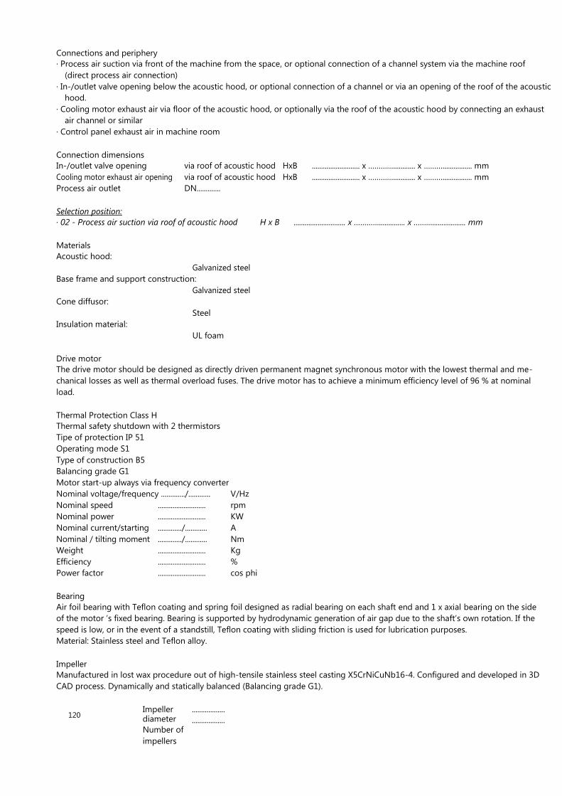
Connections and periphery
· Process air suction via front of the machine from the space, or optional connection of a channel system via the machine roof
(direct process air connection)
· In-/outlet valve opening below the acoustic hood, or optional connection of a channel or via an opening of the roof of the acoustic
hood.
· Cooling motor exhaust air via floor of the acoustic hood, or optionally via the roof of the acoustic hood by connecting an exhaust
air channel or similar
· Control panel exhaust air in machine room
Connection dimensions
In-/outlet valve opening
Cooling motor exhaust air opening
Process air outlet
via roof of acoustic hood
via roof of acoustic hood
DN.............
HxB
HxB
.......................... x …………............ x ………................ mm
.......................... x …………............ x ………................ mm
Selection position:
· 02 - Process air suction via roof of acoustic hood
Materials
Acoustic hood:
Galvanized steel
Base frame and support construction:
Galvanized steel
Cone diffusor:
Steel
Insulation material:
UL foam
H x B ............................ x ………….............. x ……….................. mm
Drive motor
The drive motor should be designed as directly driven permanent magnet synchronous motor with the lowest thermal and me-
chanical losses as well as thermal overload fuses. The drive motor has to achieve a minimum efficiency level of 96 % at nominal
load.
Thermal Protection Class H
Thermal safety shutdown with 2 thermistors
Tipe of protection IP 51
Operating mode S1
Type of construction B5
Balancing grade G1
Motor start-up always via frequency converter
Nominal voltage/frequency ............./............ V/Hz
Nominal speed
Nominal power
Nominal current/starting
Nominal / tilting moment
Weight
Efficiency
Power factor
..........................
..........................
............./............
............./............
..........................
..........................
..........................
rpm
KW
A
Nm
Kg
%
cos phi
Bearing
Air foil bearing with Teflon coating and spring foil designed as radial bearing on each shaft end and 1 x axial bearing on the side
of the motor ’s fixed bearing. Bearing is supported by hydrodynamic generation of air gap due to the shaft’s own rotation. If the
speed is low, or in the event of a standstill, Teflon coating with sliding friction is used for lubrication purposes.
Material: Stainless steel and Teflon alloy.
Impeller
Manufactured in lost wax procedure out of high-tensile stainless steel casting X5CrNiCuNb16-4. Configured and developed in 3D
CAD process. Dynamically and statically balanced (Balancing grade G1).
120
Impeller diameter
Number of
impellers
..................
..................

mm
units

In-/outlet valve
· Electronically controlled by solenoid valve and internal control, for starting/shutting down the turbo blower against external
tank pressure, closing and opening times are individually parametrised and determined using the real operating point on
blower characteristic diagram
· Valve conical seal using rubber membrane, spring-loaded
· Housing cast from aluminium pressure casting
· Pneumatic valve mounted to cone diffusor
· Pipeline silencer integrated to valve outlet
Motor cooling
· The drive motor of the ranges AT 150 to 400 is cooled successfully by a separate cooling air turbo blower which is adapted to
the requirements of the given operating point by regulating the speed. Using this technology ensures optimal cooling with
losses kept to a minimum and keeping the motor as small as possible. The cooling impeller should be mechanically decoupled
from the shaft of the main motor to ensure that the cooling impeller can operate as energetically efficient as possible
· Integrated piping silencer for cooling motor exhaust air
· Cooling air blower unit: Consists of permanent magnet drive motor and blower unit directly flanged on. Continuous motor shaft,
speed regulation dependent on load point of main drive motor, via frequency converter. Electric connection (400-500V 50/60 Hz)
Construction
· Spiral housing out of aluminium pressure casting
· Shafts and impellers statically and dynamically balanced (balancing grade G1)
· Shaft, impeller and motor housing made of stainless steel
· The blower unit with impeller and spiral casing which is directly flanged onto the motor housing.
The blower impeller is mounted directly onto the drive shaft of the motor. Shaft seal between blower unit and motor housing
via labyrinth seal.
· Bearing of shaft axially and radially via oil-free air foil bearing consisting of spring foil package with Teflon coating.
· Frequency converter for continious control of cooling air quantity.
Control panel/frequency converter
The frequency converter and all of its performance electronics and accessories are designed in accordance with EN 1800-3/EN50082,
Spark disturbance level Category C2 for industrial networks. To comply with EMV guidelines and to protect from system perturbations
and / or fluctuations, an RFI filter and at least two intermediate circuit inductors should be used. The frequency converter has a
minimum efficiency degree of 96 - 98% depending on the load point. The option of using an additional harmonic filter for THD
values < 15% should be considered. The control panel has protection class IP 55.
· Frequency converter with excess current and thermal emergency-off, overvoltage protection at the inlet of the varistors and
control of inlet phases. Monitoring of the outlet if the output performance is too high (short-circuit proof). Monitoring of in-
termediate circuit voltage over-/undervoltage
· Sensor-less current control of the drive, for extremely quick speed setting in the case of fluctuating operating conditions. Con-
tinuous speed/frequency control. Load-dependent regulation of inverter intermediate circuit voltage as well as outlet voltage
and current (closed loop) to reach the optimum operating speed and efficiency, depending on the ambient conditions. Power
panel should be designed as a high frequency application with controlled intermediate circuit voltage and adapted performance
topology. Pure software solutions are not permitted.
· Drive motor and frequency converter are coordinated and parameterised for each other using the hardware and software con-
structions. The use outside a high frequency turbo application is not possible.
· The cooling occurs exclusively via radial fans which convey filtered air using the cooling bodies of the frequency converter.
· There must be enough room onsite to repair and check/inspect the frequency converter on location.
· The control panel is equipped with a circuit breaker to protect from overloading and short circuits. Furthermore, an Emergency-
Stop implemented as a rotary switch is necessary in accordance with Machine Directive 2006/42/EG
· AERZEN High-Rise-to-Surge / active pump protection on basis motor current. Due to the extremely quick control of the DC line
current and the resulting adaptation of the blower speed in just a few milliseconds, a blower pumping is actively prevented
when the loads change quickly and the pressure increases. This property influences the operational safety of the process, par-
ticularly when the unit operates in combination with flow and displacement units.
121
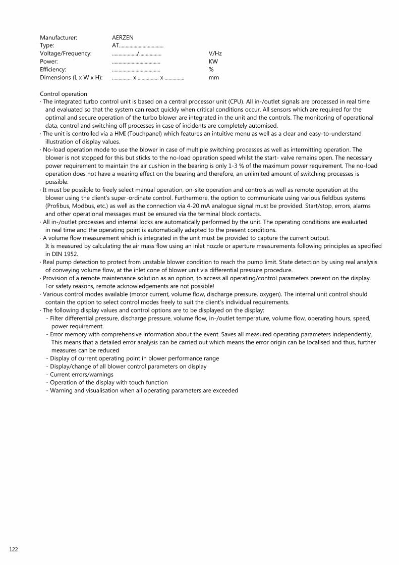
Manufacturer:
Type:
AERZEN
AT..................................
Voltage/Frequency:
Power:
Efficiency:
Dimensions (L x W x H):
.................../.................
.....................................
.....................................
............... x ................ x ...............
V/Hz
KW
%
mm
Control operation
· The integrated turbo control unit is based on a central processor unit (CPU). All in-/outlet signals are processed in real time
and evaluated so that the system can react quickly when critical conditions occur. All sensors which are required for the
optimal and secure operation of the turbo blower are integrated in the unit and the controls. The monitoring of operational
data, control and switching off processes in case of incidents are completely automised.
· The unit is controlled via a HMI (Touchpanel) which features an intuitive menu as well as a clear and easy-to-understand
illustration of display values.
· No-load operation mode to use the blower in case of multiple switching processes as well as intermitting operation. The
blower is not stopped for this but sticks to the no-load operation speed whilst the start- valve remains open. The necessary
power requirement to maintain the air cushion in the bearing is only 1-3 % of the maximum power requirement. The no-load
operation does not have a wearing effect on the bearing and therefore, an unlimited amount of switching processes is
possible.
· It must be possible to freely select manual operation, on-site operation and controls as well as remote operation at the
blower using the client‘s super-ordinate control. Furthermore, the option to communicate using various fieldbus systems
(Profibus, Modbus, etc.) as well as the connection via 4-20 mA analogue signal must be provided. Start/stop, errors, alarms
and other operational messages must be ensured via the terminal block contacts.
· All in-/outlet processes and internal locks are automatically performed by the unit. The operating conditions are evaluated
in real time and the operating point is automatically adapted to the present conditions.
· A volume flow measurement which is integrated in the unit must be provided to capture the current output.
It is measured by calculating the air mass flow using an inlet nozzle or aperture measurements following principles as specified
in DIN 1952.
· Real pump detection to protect from unstable blower condition to reach the pump limit. State detection by using real analysis
of conveying volume flow, at the inlet cone of blower unit via differential pressure procedure.
· Provision of a remote maintenance solution as an option, to access all operating/control parameters present on the display.
For safety reasons, remote acknowledgements are not possible!
· Various control modes available (motor current, volume flow, discharge pressure, oxygen). The internal unit control should
contain the option to select control modes freely to suit the client‘s individual requirements.
· The following display values and control options are to be displayed on the display:
- Filter differential pressure, discharge pressure, volume flow, in-/outlet temperature, volume flow, operating hours, speed,
power requirement.
- Error memory with comprehensive information about the event. Saves all measured operating parameters independently.
This means that a detailed error analysis can be carried out which means the error origin can be localised and thus, further
measures can be reduced
- Display of current operating point in blower performance range
- Display/change of all blower control parameters on display
- Current errors/warnings
- Operation of the display with touch function
- Warning and visualisation when all operating parameters are exceeded
122

Technical data packaged unit
Make
Type of protection IP
Type
Nominal power
Nominal current
Inlet voltage
Inlet frequency
Outlet voltage
Outlet frequency
Power factor
Cooling medium
Electric Filter
Unit weight
........................................
........................................
........................................
........................................ KVA
........................................ A
........................................ V
........................................ Hz
........................................ V
........................................ Hz
........................................ cos phi
........................................
........................................
........................................ Kg
Dimensions frequency converter (H x W x D) ...........x............x........... mm
Accessories
Selection items
· 01 - Bellow type expansion joint DN..............
Bellow type expansion joint with guiding pipe and length limiter, metal bellows and guiding pipe made of
stainless steel 1.4541, welding neck flange out of steel black S235JR.
· 02 - check valve
Material: Aluminium cast / stainless steel
check valve on the discharge side of the turbo blower, flange seal and mounting material
Selection items special accessories
· 02 - Bellow type expansion joint with guiding pipe and length limiter, metal bellows and guiding pipe made of stainless steel
1.4541, welding neck flange made of stainless steel 1.4541
· 03 - check valve made of stainless steel 1.4301
· 04 - Discharge silencer for piping
a) Absorption discharge silencer made of black steel, version of discharge silencer in accordance with DGRL 97/23/E, flange
seals and mounting materials.
b) Absorption discharge silencer made of stainless steel 1.4301, version of discharge silencer in accordance with DGRL 97/23/E,
flange seals and mounting materials
· 05 - Remote maintenance system Aerzen Turbo S-1200
Remote maintenance system AT S 1200 to monitor all operating data on the display. Furthermore, a continuous recording of
data is available. Errors and alarm messages are transmitted directly to the AERZEN service if requested (Fault tracking).
Therefore, shorter reaction times are kept which increases the operational safety and reduces service deployment costs.
The data transfer using mobile communications does not depend on connections at the installation site. Therefore, no further
expensive configurations or safety-critical actions are necessary (data protection).
123

MAINTENANCE:
Preventative maintenance
Process air and cooling air filter replacement, monthly check
of process and cooling air filter. Replacement interval according
to filter differential pressure display.
Every 3 months
Annually
Interval
Maintenance work
Filter inspection:
· Intake filter see Chapter 8.4.2 „Check and
replace intake filter and filter bags“ on
page 133)
· Filter bags (see Chapter 8.4.2 „Check and
replace intake filter and filter bags“ on
page 133)
· Filter element (see Chapter 8.4.3 „Check
and replace filter element“ on page 135)
Clean inlet and outlet air orifice and outlet air
openings (see Chapter 8.4.4 „Clean inlet and
outlet air orifice and outlet air openings“ on
page 137):
· Inlet air orifice of control panel
· Inlet air orifice of suction opening
· Rear orifice control panel
· Exhaust air opening of start unloading
device (BOV)
· Exhaust air opening of cooling system
EMERGENCY-STOP to be checked for function
Personnal
Service personnal
Operator
Authorized person
(see Chapter 8.4.5 „Check EMERGENCY-STOP
button for function“ on page 138)
Note: All intervals specified are manufacturer’s recommendations.
124

125

1500 [
59.0
6 in
]
1280 [
50.4
1
in]
1900 [
74.8
in
]
1095 [
43.1
in
] 630 [
24.8
in
]
240 [
9.4
6 in
]
TECHNICAL DRAWINGS.
AERZEN TURBO AT 150 - 0.6 S
Abluft
E-Technik
Exhaust air
E-technology
Option Kabeleinführung durch Fundament
Option cable entry through foundation
450 [17.74 in]
1850 [72.83 in]
1170 [46.06 in]
1350 [53 1/4 in]
Standard Kabeleinführung
Standard cable entry
1040 [40.94 in]
Freiraum für Wartung
free space for maintenance
760 [29.91 in]
200 [7.87 in]
185 [7.28 in] 150 [5.91 in]
550 [21.65 in]
Freiraum für Wartung
free space for maintenance
425 [16.73 in]
120 [4.72 in]
DN [ANSI]
315 [12.41 in]
705 [27.76 in]
126
1500 [59.06 in]
Drawing no.: GA-900003-01
1350 [53.16 in] 1000 [39.37 in]

1500 [
59.0
6 in
]
1280 [
50.4
1
in]
1900 [
74.8
in
]
1095 [
43.1
in
] 630 [
24.8
in
]
240 [
9.4
6 in
]
AERZEN TURBO AT 150 - 0.8 S
Abluft E-Technik
Exhaust air
E-technology
Option Kabeleinführung durch Fundament
Option cable entry through foundation
450 [17.74 in]
1850 [72.83 in]
1170 [46.06 in]
1350 [53 1/4 in]
Standard Kabeleinführung
Standard cable entry
1040 [40.94 in]
Freiraum für Wartung
free space for maintenance
760 [29.91 in]
200 [7.87 in]
185 [7.28 in] 150 [5.91 in]
550 [21.65 in]
Freiraum für Wartung
free space for maintenance
425 [16.71 in]
120 [4.72 in]
DN [ANSI]
315 [12.41 in]
705 [27.76 in]
1500 [59.06 in] 1350 [53.16 in] 1000 [39.37 in]
Drawing no.: GA-900002-02
127

1500 [
59.0
6 in
]
1280 [
50.4
1
in]
1900 [
74.8
in
]
1095 [
43.1
in
] 630 [
24.8
in
]
240 [
9.4
6 in
]
AERZEN TURBO AT 150 - 1.0 S
Abluft E-Technik
Exhaust air
E-technology
Option Kabeleinführung durch Fundament
Option cable entry through foundation
450 [17.74 in]
1850 [72.83 in]
1170 [46.06 in]
1350 [53 1/4 in]
Standard Kabeleinführung
Standard cable entry
1040 [40.94 in]
Freiraum für Wartung
free space for maintenance
760 [29.91 in]
200 [7.87 in]
185 [7.28 in] 150 [5.91 in]
550 [21.65 in]
Freiraum für Wartung
free space for maintenance
425 [16.71 in]
120 [4.72 in]
DN [ANSI]
315 [12.41 in]
705 [27.76 in]
128
1500 [59.06 in]
Drawing no.: GA-900006-00
1350 [53.16 in] 1000 [39.37 in]

1500 [
59.0
6 in
]
1280 [
50.4
1
in]
1900 [
74.8
in
]
1095 [
43.1
in
] 630 [
24.8
in
]
240 [
9.4
6 in
]
AERZEN TURBO AT 200 - 0.8 S
Abluft E-Technik
Exhaust air
E-technology
Option Kabeleinführung durch Fundament
Option cable entry through foundation
450 [17.74 in]
1850 [72.83 in]
1170 [46.06 in]
1350 [53 1/4 in]
Standard Kabeleinführung
Standard cable entry
1040 [40.94 in]
Freiraum für Wartung
free space for maintenance
760 [29.91 in]
200 [7.87 in]
185 [7.28 in] 150 [5.91 in]
550 [21.65 in]
Freiraum für Wartung
free space for maintenance
425 [16.71 in]
120 [4.72 in]
DN [ANSI]
315 [12.41 in]
705 [27.76 in]
1500 [59.06 in] 1350 [53.16 in] 1000 [39.37 in]
Drawing no.: GA-900004-01
129

1500 [
59.0
6 in
]
1280 [
50.4
1
in]
1900 [
74.8
in
]
1095 [
43.1
in
] 630 [
24.8
in
]
240 [
9.4
6 in
]
AERZEN TURBO AT 200 - 1.0 S
Abluft E-Technik
Exhaust air
E-technology
Option Kabeleinführung durch Fundament
Option cable entry through foundation
450 [17.74 in]
1850 [72.83 in] Standard Kabeleinführung 1040 [40.94 in] Standard cable entry
1170 [46.06 in]
1350 [53.15 in]
Freiraum für Wartung
free space for maintenance 760 [29.91 in]
200 [7.87 in]
185 [7.28 in] 150 [5.91 in]
550 [21.65 in]
Freiraum für Wartung
free space for maintenance
425 [16.71 in]
120 [4.72 in]
DN [ANSI]
315 [12.41 in]
705 [27.76 in]
130
1500 [59.06 in]
Drawing no.: GA-900005-01
1350 [53.16 in] 1000 [39.37 in]

2100 [
82.6
8 in
]
1676 [
66
in]
200 [
7.8
7 in
]
705 [
27.7
7
in]
2500 [
98.4
3 in
]
DN
500 P
N
10
1360 [
53.5
4 in
]
850 [
33.4
6 in
]
280 [
11.0
2
in]
AERZEN TURBO AT 300 - 0.6 T
Abluft
E-Technik
Exhaust air
E-technology
2055 [80.91 in]
2450 [96.46 in]
210 [8.27 in]
205 [8.07 in]
205 [8.07 in]
Standard Kabeleinführung
Standard cable entry
Freiraum für Wartung free space for maintenance
940 [37.03 in]
815 [32.08 in]
700 [27.56 in]
Freiraum für Wartung free space for maintenance
240 [9.45 in]
1500 [59.06 in] 550 [21.65 in] 2055 [80.91 in] 1000 [39.37 in]
Drawing no.: GA-900009-00
131

2100 [
82.6
8 in
]
1676 [
66
in]
200 [
7.8
7 in
]
705 [
27.7
7
in]
2500 [
98.4
3 in
]
DN
400 P
N
10
1360 [
53.5
4 in
]
850 [
33.4
6 in
]
280 [
11.0
2
in]
AERZEN TURBO AT 300 - 0.8 T
Abluft
E-Technik
Exhaust air
E-technology
2055 [80.91 in]
2450 [96.46 in]
210 [8.27 in]
205 [8.07 in]
205 [8.07 in]
Standard Kabeleinführung
Standard cable entry
Freiraum für Wartung
free space for maintenance
940 [37.03 in]
815 [32.08 in]
700 [27.56 in]
Freiraum für Wartung free space for maintenance
240 [9.45 in]
550 [21.65 in]
132
Drawing no.: GA-900010-00
1500 [59.06 in] 2055 [80.91 in] 1000 [39.37 in]

2100 [
82.6
8 in
]
1676 [
66
in]
200 [
7.8
7 in
]
705 [
27.7
7
in]
2500 [
98.4
3 in
]
DN
400 P
N
10
1360 [
53.5
4 in
]
850 [
33.4
6 in
]
280 [
11.0
2
in]
AERZEN TURBO AT 300 - 1.0 T
Abluft
E-Technik
Exhaust air
E-technology
2055 [80.91 in]
2450 [96.46 in]
210 [8.27 in]
205 [8.07 in]
205 [8.07 in]
Standard Kabeleinführung
Standard cable entry
Freiraum für Wartung
free space for maintenance
940 [37.03 in]
815 [32.08 in]
700 [27.56 in]
Freiraum für Wartung free space for maintenance
240 [9.45 in]
550 [21.65 in]
1500 [59.06 in] 2055 [80.91 in] 1000 [39.37 in]
Drawing no.: GA-900011-00
133

2100 [
82.6
8 in
]
1676 [
66
in]
200 [
7.8
7 in
]
705 [
27.7
7
in]
2500 [
98.4
3 in
]
DN
500 P
N
10
1360 [
53.5
4 in
]
850 [
33.4
6 in
]
280 [
11.0
2
in]
AERZEN TURBO AT 400 - 0.8 T
Abluft
E-Technik
Exhaust air
E-technology
2055 [80.91 in]
2450 [96.46 in]
210 [8.27 in]
205 [8.07 in]
205 [8.07 in]
Standard Kabeleinführung
Standard cable entry
Freiraum für Wartung
free space for maintenance
940 [37.03 in]
815 [32.08 in]
700 [27.56 in]
Freiraum für Wartung free space for maintenance
240 [9.45 in]
1500 [59.06 in] 550 [21.65 in] 2055 [80.91 in] 1000 [39.37 in]
Drawing no.: GA-900012-00
134

135
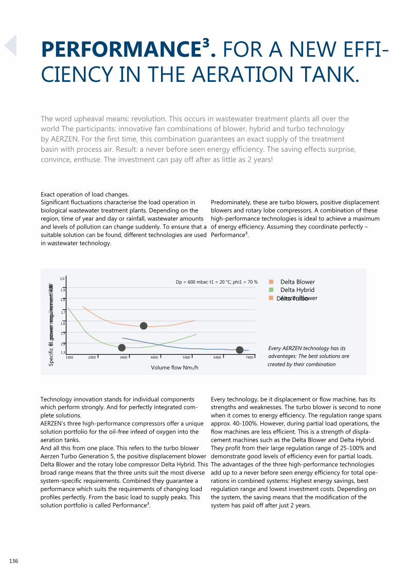
Sp
eci
fic
fl. p
ow
er
req
uir
em
en
t kW
el.
po
wer
req
uir
em
en
t kW
Delta Turbo
PERFORMANCE³. FOR A NEW EFFI- CIENCY IN THE AERATION TANK.
The word upheaval means: revolution. This occurs in wastewater treatment plants all over the
world The participants: innovative fan combinations of blower, hybrid and turbo technology
by AERZEN. For the first time, this combination guarantees an exact supply of the treatment
basin with process air. Result: a never before seen energy efficiency. The saving effects surprise,
convince, enthuse. The investment can pay off after as little as 2 years!
Exact operation of load changes.
Significant fluctuations characterise the load operation in
biological wastewater treatment plants. Depending on the
region, time of year and day or rainfall, wastewater amounts
and levels of pollution can change suddenly. To ensure that a
suitable solution can be found, different technologies are used
in wastewater technology.
Predominately, these are turbo blowers, positive displacement
blowers and rotary lobe compressors. A combination of these
high-performance technologies is ideal to achieve a maximum
of energy efficiency. Assuming they coordinate perfectly –
Performance³.
2,0
1,9
1,8
1,7
1,6
1,5
Dp = 600 mbar; t1 = 20 °C; phi1 = 70 %
■ Delta Blower
■ Delta Hybrid
■ AerzenBlower
1,4
1,3
1400
2400
3400
4400
5400
6400
7400
Every AERZEN technology has its
advantages: The best solutions are
136
Volume flow Nm3/h
Technology innovation stands for individual components
which perform strongly. And for perfectly integrated com-
plete solutions.
AERZEN's three high-performance compressors offer a unique
solution portfolio for the oil-free infeed of oxygen into the
aeration tanks.
And all this from one place. This refers to the turbo blower
Aerzen Turbo Generation 5, the positive displacement blower
Delta Blower and the rotary lobe compressor Delta Hybrid. This
broad range means that the three units suit the most diverse
system-specific requirements. Combined they guarantee a
performance which suits the requirements of changing load
profiles perfectly. From the basic load to supply peaks. This
solution portfolio is called Performance³.
created by their combination
Every technology, be it displacement or flow machine, has its
strengths and weaknesses. The turbo blower is second to none
when it comes to energy efficiency. The regulation range spans
approx. 40-100%. However, during partial load operations, the
flow machines are less efficient. This is a strength of displa-
cement machines such as the Delta Blower and Delta Hybrid.
They profit from their large regulation range of 25-100% and
demonstrate good levels of efficiency even for partial loads.
The advantages of the three high-performance technologies
add up to a never before seen energy efficiency for total ope-
rations in combined systems: Highest energy savings, best
regulation range and lowest investment costs. Depending on
the system, the saving means that the modification of the
system has paid off after just 2 years.
137

ACCESSORIES FOR WASTEWATER TECHNOLOGY.
EXTERNAL POWER CABINET For Delta Blower and Delta Hybrid
External power cabinet with integrated frequency converter
(without AERZEN control)
· Best solution for stepless start-up and speed change (due
to adjustable current limiting, high currents in the electri-
cal network are prevented)
· Enables smooth speed (frequency) control
· Less strain on the network during start-up
· Thanks to process optimisation (Adjustment of motor
speed) => Energy efficient)
· High relative starting torque for low current
Characteristics
· operating voltage: 400 V/50 Hz or 460 V/60 Hz
· Performance range: 3 kW – 710 kW
· For systems with a constant torque progression (positive
displacement blower, rotary lobe compressor and screw
compressor)
· Housing protection (hazardous area) IP54
· TN network configuration
· Indoor installation (tempered, non-ex free space)
· Ambient temperature max. 35°C (Average value/24h)
· 1000 m above sea level
· Signal for motor excess temperature
Requirements:
· Motor speed specification at site
· Wiring work from power cabinet to motor supplied by the
customer
· Wiring works PTC resistor monitoring to power cabinet at
site
· Delivery, laying and connection of cables to be carried out
at site
Options:
· Conventional control
· Acoustic hood installation (integrated solution) up to
160kW
· outdoor installation
· System in Ex area
· (Connection instrumentation in ex-design / power cabinet
ex-free)
· Different voltages (380V-690V)
· Network forms TN/TT/IT network
· Cabinet heater to avoid condensation
· Ambient temperatures up to 50°C
· Frequency converter interface optionally as Profibus-
Profinet - Modbus etc.
Scope of supply
·
·
·
·
·
Main switch/Design Power switch
Control transformer incl. primary and secondary saving
Emergency-stop relay + Emergency-stop button
Mains contactor
Frequency converter incl. line reactor, HF filter and motor
choke
· Frequency converter operating panel
· Delivery terminal block for connection to an overriding sys-
tem
138

Line reactor
FC with footprint filter
Motor choke
139

FREQUENCY CONVERTER WITH ACCESSORIES
Characteristics
· Low switching loss due to IGBT power supply panel
· Low noise development due to high switching frequencies
· Comprehensive hardware protection for current, voltage
and temperature
· Voltage and current monitoring in static and dynamic
operation
· Limited resistance to short-circuiting and earth faults
· Hardware current control
· Integrated fan
· Analog input: 0 to 10V / (0)4 to 20mA
· Analog output: 0 to 10 V
· Programmable digital inputs
Dimensions and weights
· Programmable outputs: e.g. relay
· Programmable parameter sets
Scope of supply:
· Pre-parameterised frequency converter
· Delivery with additional components «Digital operator»
(without RS232/485 interface)
· Including HF filter
· Including power / motor choke (depending on
performance)
· From 450 kW, available with additional synchronisation
choke
3
4
5,5
7,5
11
15
18,5
22
30
37
45
55
75
90
110
132
160
200
250
315
355
400
450
500
560
630
710
Performance [kW]
75
75
75
80
80
80
150
160
170
170
280
280
280
280
500
500
500
750
750
900
1000
1000
1300
1300
1800
1800
1800
Weight [kg]
Dimensions [WxHxD; mm]
760x760x300
760x760x300
760x760x300
760x760x300
760x760x300
760x760x300
800x1000x400
800x1000x400
800x1000x400
800x1000x400
1000x1400x400
1000x1400x400
1000x1400x400
1200x1400x500
1000x1200x600
1000x1200x600
1000x1200x600
1600x2000x600
1600x2000x600
2200x2000x600
2200x2000x600
2200x2000x600
2400x2000x600
2400x2000x600
3200x2000x600
3200x2000x600
3200x2000x600
Design as:
Wall cabinet
Wall cabinet
Wall cabinet
Wall cabinet
Wall cabinet
Wall cabinet
Wall cabinet
Wall cabinet
Wall cabinet
Wall cabinet
Standing cabinet
Standing cabinet
Standing cabinet
Standing cabinet
Standing cabinet
Standing cabinet
Standing cabinet
Standing cabinet
Standing cabinet
Standing cabinet
Standing cabinet
Standing cabinet
Standing cabinet
Standing cabinet
Standing cabinet
Standing cabinet
Standing cabinet
Dimensions and weights of the power cabinets are defined according to the nominal power as well as the cabinet design.
140

INTEGRATED POWER CABINET WITH FREQUENCY CONVERTER IN ACOUSTIC HOOD (ONLY UP TO 160 KW)
The power supply panel is integrated into the unit below the
acoustic hood. It is delivered with the unit completely wired
and is operational. The AERZEN control unit «AERtronic» is
necessary to operate the system. Please consider the addi-
tional cost for the AERtronic extension module «Frequency
converter control», see above.
> only for indoor installation - Ambient temperature - 10°C
to + 35 °C
Currently, the power supply panels with FC are used for
the following units.
Unit type
Positive displacement blower - DB
Rotary lobe compressor - DH
Unit size
GM10S, GM15L, GM25S, GM30L, GM35S, GM50L, GM60S
D12S/E/H, D17L, D24S/E/H, D28L, D36S/E/H, D46L, D52S, D62S/E/H
141

SILENCER.
As already described, pipe sounds can have a significant impact on the sound perception of the entire
ventilation unit. The pipe sound depends significantly on the individual pipework. It is possible to
install additional damping directly downstream of the noise source to reduce sounds which are too
loud.
Even the standard versions of AERZEN products are de-
signed, to supply absorption-material free process air. That
means that the silencers integrated into the discharge side of
the unit are designed in metal and operate using an interfer-
ence principle. This has different advantages:
The porous absorption material dissolves into small and larg-
er pieces. The smaller pieces reach the water via the fans. The
larger pieces get caught in the fan elements and block the
openings for the fine-bubble ventilation. As these blockages
worsen, the counter pressure increases and, thus, the neces-
sary power consumption for the ventilation.
· The process gas has the necessary quality and purity.
· The noise development on the discharge side compared to
Due to the discontinuous thermal load, the pressure load and
pulsations, the fibres of the absorption material, which is
often made from plastics, dissolve after a certain operating
time. This means they end up in the gas and, if they are suf-
ficiently small, travel through the fan into the water which is
due to be cleaned.
the total operation period of the packaged unit remains
constant
It is the job of the absorption material to absorb sound. That
means that the silencer loses its soundproofing properties as
the absorption material diminishes.
· The energy efficiency remains constant
Example for the sound development compared to usage time
Pipeline sound level with
constant volume flow 30m³/min with 600mbar (g)
Sound level [dB(A)]
158
156
154
152
150
148
146
144
AERZEN standard discharge
silencer (without absorption
material)
Discharge silencer with ab-
sorption material
Poly. (AERZEN standard
discharge silencer (without
absorption material)
Poly. (Discharge silencer with
absorption material)
142 0
0,5
1
1,5
2
2,5
3
3,5
4
4,5
Operating time [years]
142

L3
L6
L3
L4
L 1
L2 L
4
L2
L3
L 1
AERZEN offers additional pipeline silencers in the following
nominal connection sizes:
· DN 100
· DN 125
· DN 150
· DN 200
· DN 250
At AERZEN, these nominal sizes are available in the follow-
ing kinds of silencers:
Slotted tube reactive silencer
Silencer constructed as slotted tube reactive silencer, with
metallic inserts and therefore without any absorption ma-
terial. The effect is created using the interference principle
which achieves a damping of -20 to -25 dB(A).
Silencer Schliro horizontal with sleeve connection
D1
Cartridge silencer
Pipeline silencer constructed as cartridge silencer. This type
of silencer achieves its effect by using conventional absorp-
tion materials. These silencers are installed in the pipeline,
which means that the thermal effect and the impact of the
conveying impulse (blower/compressor stage) only have a
minimal effect on the erosion of the absorption material. A
damping effect of -8 to -10 dB(A) can be achieved.
Silencer Schliro vertical with sleeve connection
D2 D1
D2
D3
Silencer with insulating cartridge sleeve connection
Silencer with insulating cartridge flange connection
143

PERFECTION MATURED OVER 150 YEARS: AERZEN’S SERVICE WoRLD.
The long service life of AERZEN machines is legendary. Why then is service a topic at all? Because
this is about more than availability and OEM original parts. AERZEN services protect your invest-
ment, productivity, the deciding advantage over the competition. All over the globe.
The AERZEN on-site service.
Our service teams work wherever the machines are. World-
wide. Onshore or Offshore. Often in extreme conditions. How
do we achieve this? With short distances. AERZEN has built
a network of service support locations and decentralised part
warehouses all over the globe for you. More than 200 excel-
lently trained service technicians are available to you. Any-
time and wherever you need them.
About Rental Service and other services.
AERZEN’s service world offers a lot. For example, tailor-
made service kits. Exchange stage, machine diagnostics,
sound-technical optimisations. One of our most important
services is the AERZEN Rental Division and offers a large
fleet of rental machines. Blowers, turbos and compressors by
AERZEN. In different performance classes. For all standard
pressure ranges. Usable immediately and delivered ready-to-
use on request. What does this mean for you? You are always
equipped, even for unexpected needs.
144

Commissioning
It goes without saying that the commissioning of
AERZEN machines onsite is part of our service.
We will do the following:
· Installation checks and alignment using lasers
· Creation of operational readiness of stage oil
filling, cooling agent, etc.
· The inspection of all safety-relevant units, such
as alarm and deactivation values or messages
to superordinate controls/control room
· Commissioning of the unit
· A test run in operating conditions over several
hours
· Preparation of a handover log
With the best recommendations of your OEM.
We have been manufacturing quality products for more than
150 years. At the same time, a suitable service world has been
developed. With tailor-made offers for each life stage of your
machine. With OEM original parts and reliable logistics and a
performance-strong service in the focus. And decentralised
service locations near you which guarantee fast supply of
spare parts and competent service - worldwide.
145

TENDER SPECIFICATIONS FOR SER- VICE AND MAINTENANCE CON- TRACTS. APPLICATIoN FoR STAND- ARD AIR MACHINES IN GERMANY.
Whether you would like a basic maintenance contract or an optimum contract for your machine
or machine configuration by AERZEN also depends on the availability of your own technical
personnel. Use your own resources accurately and only “purchase” those external capacities which
you really need. Our service packages leave a lot of room for design possibilities for individual
agreements.
BASIC MAINTENANCE CONTRACTS
Service contract: Partial maintenance 1
146
The work scope includes the inspection and maintenance of
units and unit parts per year. Inspection and maintenance
works are carried out according to the maintenance plan of
the manufacturer ’s operating manual.
The inspection of units contains determination of smoothness,
stage clearances, the oil level and oil density, and also the
conveying chamber. The pressure valve (safety valve), the start
unloading device (if it exists) and the check valve are inspected.
The maintenance work includes the oil replacement, the
replacement of suction filters and the components for power
transfer (V-belt, compression sleeves). The construction parts
of the transmission are aligned. The carried out work is docu-
mented in a checklist with notes for further work, if necessary.
Service contract: Partial maintenance 2
The work scope includes the inspection and maintenance of
units and unit parts per year. Inspection and maintenance
work is carried out according to the maintenance plan of the
manufacturer ’s operating manual.
The inspection of units contains an assessment of smooth-
ness, stage clearances, the oil level and oil density, and also
the conveying chamber. The pressure valve (safety valve), the
start unloading device (if it exists) and the check valve.
The maintenance work includes the oil replacement, the
replacement of suction filters and the components for power
transfer (V-belt, compression sleeves). The construction parts
of the transmission are aligned. The carried out work is docu-
mented in a checklist with notes for further work, if necessary.
Contract properties
· Contract period 3 years
· one service call per year
· Use of Aerzen oEM parts
· Wear parts are invoiced in addition to the annual fee
· 6 months warranty on all work carried out and in-
stalled parts
· Maintenance fee incl. travel expenses as well as ac-
commodation and food costs
Contract properties
· Contract period 3 years
· one service call per year
· Use of Aerzen oEM parts
· Wear parts included in the annual fee
· 6 months warranty on all work carried out and in-
stalled parts
· Maintenance fee incl. travel expenses as well as ac-
commodation and food costs

OPTIMUM MAINTENANCE CONTRACTS
Service contract: Servicing
The work scope includes one inspection and maintenance of
units each and unit parts as well as any necessary service
calls per year. Inspection and maintenance works are carried
out according to the maintenance plan of the manufacturer ’s
operating manual. The inspection of units contains determi-
nation of smoothness, stage clearances, the oil level and oil
density, and also the conveying chamber. The pressure valve
(safety valve), the start unloading device (if it exists) and the
check valve are inspected. The maintenance work includes
the oil replacement, the replacement of intake filters and the
components for power transfer (V-belt, compression sleeves).
The construction parts of the transmission are aligned. The
carried out work is documented in a checklist with notes for
further work, if necessary. This work is carried out at the next
service call.
Service contract: Complete maintenance
The work scope includes the inspection and maintenance of
units and unit parts as well as any necessary service calls per
year. Inspection and maintenance works are carried out accord-
ing to the maintenance plan of the manufacturer ’s operating
manual. The inspection of units contains determination of
smoothness, stage clearances, the oil level and oil density,
and also the conveying chamber. The pressure valve (safety
valve), the start unloading device (if it exists) and the check
valve are inspected.
The maintenance work includes the oil replacement, the
replacement of intake filters and the components for power
transfer (V-belt, compression sleeves). The construction parts
of the transmission are aligned. Worn spare parts are replaced.
The carried out work is documented in a checklist with notes
for further work, if necessary.
Service contract: Delta Care (Warranty extension)
The service contract contains the inspection and maintenance
of units per year. Inspection and maintenance works are carried
out according to the maintenance plan of the manufacturer ’s
operating manual.
The inspection of the unit(s) contains the assessment of the
smoothness, clearance of the stage, inspection of oil levels and
the oil density. The inspection of installed unit components.
The maintenance works include the oil replacement, the
replacement of intake filters and the components for power
transfer (V-belt, compression sleeves). The construction parts
of the transmission are aligned. The carried out work is docu-
mented in a checklist with notes for further work, if necessary.
Contract properties
· Contract period 5 years
· one service call per year
· Use of Aerzen oEM parts
· Wear and spare parts are included in the fee
· Warranty throughout the contract period
· A general inspection during the contract period
· Maintenance fee incl. travel expenses as well as ac-
commodation and food costs.
Contract properties
· Contract period 5 years
· Two service calls, inspections and maintenance per
year
· More detailed service calls
· Use of Aerzen oEM parts.
· Wear and spare parts are included in the fee.
· Warranty throughout the contract period
· Maintenance fee incl. travel expenses as well as ac-
commodation and food costs.
· 24/7 Service
Contract properties
· Can be used in standard new machines, installation in
Germany
· Conveyed medium Air
· Contract conclusion before commissioning
· Period variable up to 5 years
· Use of Aerzen oEM parts
· Wear parts and equipment are invoiced separately
· Spare parts included in the annual fee
· Warranty throughout the contract period
· Maintenance fee incl. travel expenses as well as ac-
commodation and food costs.
147

WEAR PARTS AND MAINTENANCE CONTRACTS.
Wear parts
Delta Blower
Air filter
V-belt
Oil
Compression sleeves/ direct drive
Service set for re-lubrication device
Aerzen Turbo
Air filter
Delta Hybrid
Air filter
V-belt
Oil / Delta Lube
Oil filter
Service set for re-lubrication device
Maintenance contract contents (standard) Blower and Hybrid
Contract type
Partial
Partial
Servicing
Complete
Warranty extension
maintenance 1 maintenance 2 maintenance
Short designation
Period
Period alternative
PM 1
3 years
1 year / automatic
PM 2
3 years
1 year / automatic
S
5 years
no
CM
5 years
no
WE
up to max. 5 years
no
renewal if not
cancelled
renewal if not
cancelled
Contract extension yes yes yes yes yes
possible
Contractual form Service contract Service contract Special-order Special-order Special-order
contract contract contract
Service calls per year
Inspection
Maintenance
Wear parts included
Oil included
Spare parts included
Stage revision
Repairs
Creation check list
Recommendation of
1
yes
yes
no
no/ available upon
client request
no
no
no
yes
yes
1
yes
yes
yes
no/ available upon
client request
no
no
no
yes
yes
2
yes
yes
yes
no/ available upon
client request
yes
1 x in 5 years
yes
yes
yes, implementa-
2
yes
yes
yes
no/ available upon
client request
yes
1 x in 5 years
yes
yes
yes, implementa-
1
yes
yes
no
no/ available upon
client request
yes
no
yes
yes
yes
further works tion by AERZEN tion by AERZEN
Dynamics
Warranty
24 h Service
Infoline Mo to Fr
3%
Work & parts
no
yes
3%
Work & parts
no
yes
3%
Operability
no
yes
3%
Operability
yes
yes
no
Operability
no
yes
8 a.m. to 12 p.m.
148

Inspection plan (Standard) Turbo
Mechanical part
· General visual inspection
· VFD cooling body cleaning (blow-off with compressed air)
· Impeller inspection
· Functional test blow-off valve
· Inspection of machines and piping connections
(leakages and screw connections)
Electric part
· Software and parameter inspection
· Inspection of software status
· Inspection of sensors
· Inspection of VFD intermediate circuit
· Text report logs and documentation
· Error log evaluation and parameter optimisation
· Alignment of blower stage
· Inspection of VFD cooling fans
· Inspection of cooling air turbo
Additional works for extended inspection
Mechanical part
· Disassembly of spiral casing
· Impeller cleaning
· Disassembly spiral casing cooling turbo
· Impeller cleaning on cooling turbo
Electric part
· Disassembly of electrolyte condensors (6 - 18 pieces)
· Inspection of electrolyte condensors (measurement of capacity)
· Inspection of semiconductors, e.g. IGBTs, SCRs
· Replacement of VFD cooling fans
· Calibration of sensors
· General visual inspection
Expected time effort for additional works: 1 to 2 days
Maintenance and inspection package Turbo
Maintenance contract Turbo: Basic 1
· Travel costs
· Annual inspection (Standard)
· Maintenance
Maintenance contract Turbo: Basic 2
(at least 4 years)
· Travel costs
· Annual inspection (Standard)
· After 4 years inspection (extended)
Maintenance contract Turbo: Professional
(at least 4 years)
· Travel costs
· Annual inspection (Standard)
· After 4 years inspection (extended)
Wear parts: not included
· Maintenance · Maintenance
· Warranty extension
(depending on effort) Wear parts: included Wear parts: not included
Spare parts: not included
(as per expenditure)
Spare parts: not included
(as per expenditure)
(as per expenditure)
Spare parts: included
149

AERZEN RENTAL DIVISION. AERZEN’S RENTAL SERVICE.
Maintenance or repair, but also unexpectedly originating requirement: There may be many
reasons to call AERZEN Rental Division, AERZEN’s international rental service. AERZEN Rental
Division supports you with rental units and accessories, offers individual solutions for research
and development, operative leasing and contracting.
150
Your company remains flexible. Your air oil-free.
Good to know that you‘re prepared! AERZEN‘s Rental Divi-
sion offers quick solutions for 100 % oil-free air. For almost
every industry segment. Ad hoc or on a contractual basis
(Service level agreement). Our fleet of rental machines in-
cludes a large number of usable blowers and compressors
of different performance levels and for all standard pressure
ranges. Our Engineering department has expert knowledge
of your applications, that is why our solutions fit your pro-
cesses so seamlessly.
Ready-to-use services.
AERZEN Rental Division is also available to you for the pro-
ject realisation and offers not only the rental units but also
transport, installation and commissioning with our own ex-
pert personnel. Of course, the service package includes regu-
lar maintenance and servicing of the machines - to ensure
you achieve your production aims without “running out of
air ”!

Around the clock, seven days a week.
The speedy service of the Aerzen Rental Division distinguish-
es itself from other providers. This starts with our hotline.
You can reach us seven days a week around the clock. We
compile an emergency plan for you. We then deliver and in-
stall the rental unit with pipelines and other desired systems.
It is connected to your production process and is started up by
the push of a button! Aerzen Rental Division has facilities all
over Europe. That means that our rental units and our Know-
how are always close by.
Services:
· Directly available rental units
· Quick delivery across Europe
· Customisation according to your specific
requests
· Extensive accessories:
· Power cable/power supply
· Pipework
· Cooler & dryer
· Ventilation plates for wastewater treatment
plants
· Projects for research and development
· Customisation according to your specific re-
quests
· Rapid service with 24/7/365 hotline
· Quick delivery from warehouses all over Europe
· Rental of extensive accessories, e.g.
· Cooler
· Air dryer
· Transformers
· Diesel generators
We support you with:
· Production downtime
· Bridging of maintenance and repair
· Process optimisation
· Production peaks
· New construction and conversion of units
· Research and development
· Backwash of filters
· Pneumatic conveying of bulk materials
· Gas conveying
· Degassing
· Dedusting
· Generation of negative pressure
· Biogas treatment and much more
· Water and wastewater treatment
· Ventilation
151

AERZEN WORLDWIDE. ALWAyS CLoSE.
It is all good and well to buy and install an AERZEN machine. But we offer more. We look after
your machine investment during its entire life cycle - for more performance and an optimal cost-
benefit relation. This requires presence. To ensure competent advice and quick service, we have
built up a network of subsidiaries and service representations all over the world. Good feeling!
152

Contact worldwide
2,000 people are employed by AERZEN. On all conti-
nents. We have six offices in Germany alone. And we
have 45 subsidiaries in more than 100 countries of the
world. This means we do not have to travel far - if you
need us. Call us:
+49 5154 81-0/ www.aerzen.com
Service-Hotline
We are there for you, even if we are not there - outside
our office hours. Call AERZEN directly via our regional
service hotlines:
+49 171 3511834
Customer Net
Where can you find out more about our company and
leading compressor technologies from Aerzen? Simple:
Using the Customer Net on our homepage. We have col-
lected everything you might want to know.
www.aerzen.com
153

CONTACT SHEET PLEASE SEND THIS To: +504 99603830
Application
intake volume flow
m³/min - m³/h
Wastewater treatment plant
Postcode, City
Number of machines
Conveying medium
Intake temperature
Intake pressure
Pressure difference
C°
bar abs
mbar
Drive type
Constant speed
Frequency converter
Motor drive
Suction
Acoustic hood
Installation
Direct
Via filter
With
Indoor
Star-delta
Via pipeline
Without
Outdoor
At FC
Instrumentation Analogue - Standard (Pressure gauge + Maintenance indicator)
Optional intake pressure/discharge pressure switch and contact thermometer
154
Instrumentation Dialogue
Company
First, last name
Street/No.
City
Comment:
AERtronic
Phone
Mobile
Fax
Ext. Interface Profibus DP

www.aerzen.com
Planmap ABWA – EN – 00 – 11.2015